JP6968453B2 - Filter insert and sample vial using the filter insert - Google Patents
Filter insert and sample vial using the filter insertDownload PDFInfo
- Publication number
- JP6968453B2 JP6968453B2JP2019551500AJP2019551500AJP6968453B2JP 6968453 B2JP6968453 B2JP 6968453B2JP 2019551500 AJP2019551500 AJP 2019551500AJP 2019551500 AJP2019551500 AJP 2019551500AJP 6968453 B2JP6968453 B2JP 6968453B2
- Authority
- JP
- Japan
- Prior art keywords
- filter
- assembly
- cylindrical body
- filter insert
- sample vial
- Prior art date
- Legal status (The legal status is an assumption and is not a legal conclusion. Google has not performed a legal analysis and makes no representation as to the accuracy of the status listed.)
- Active
Links
- 239000000463materialSubstances0.000claimsdescription179
- -1polytetrafluoroethylenePolymers0.000claimsdescription35
- 239000002861polymer materialSubstances0.000claimsdescription24
- 229920002313fluoropolymerPolymers0.000claimsdescription22
- 230000002209hydrophobic effectEffects0.000claimsdescription21
- 229920000642polymerPolymers0.000claimsdescription15
- 239000012530fluidSubstances0.000claimsdescription14
- 239000004696Poly ether ether ketoneSubstances0.000claimsdescription12
- 229920001281polyalkylenePolymers0.000claimsdescription12
- 229920006260polyaryletherketonePolymers0.000claimsdescription12
- 229920002530polyetherether ketonePolymers0.000claimsdescription12
- 239000004697PolyetherimideSubstances0.000claimsdescription9
- 239000004372Polyvinyl alcoholSubstances0.000claimsdescription9
- 238000000605extractionMethods0.000claimsdescription9
- 229920002239polyacrylonitrilePolymers0.000claimsdescription9
- 239000004417polycarbonateSubstances0.000claimsdescription9
- 229920001601polyetherimidePolymers0.000claimsdescription9
- 229920001343polytetrafluoroethylenePolymers0.000claimsdescription9
- 239000004810polytetrafluoroethyleneSubstances0.000claimsdescription9
- 239000011118polyvinyl acetateSubstances0.000claimsdescription9
- 229920002689polyvinyl acetatePolymers0.000claimsdescription9
- 229920002451polyvinyl alcoholPolymers0.000claimsdescription9
- 239000004812Fluorinated ethylene propyleneSubstances0.000claimsdescription6
- 239000002033PVDF binderSubstances0.000claimsdescription6
- 239000004952PolyamideSubstances0.000claimsdescription6
- 239000004642PolyimideSubstances0.000claimsdescription6
- 229920003235aromatic polyamidePolymers0.000claimsdescription6
- 125000003118aryl groupChemical group0.000claimsdescription6
- 230000000712assemblyEffects0.000claimsdescription6
- 238000000429assemblyMethods0.000claimsdescription6
- 229920001971elastomerPolymers0.000claimsdescription6
- 239000000806elastomerSubstances0.000claimsdescription6
- 239000004811fluoropolymerSubstances0.000claimsdescription6
- UQSQSQZYBQSBJZ-UHFFFAOYSA-Nfluorosulfonic acidChemical compoundOS(F)(=O)=OUQSQSQZYBQSBJZ-UHFFFAOYSA-N0.000claimsdescription6
- 229920009441perflouroethylene propylenePolymers0.000claimsdescription6
- 239000010702perfluoropolyetherSubstances0.000claimsdescription6
- 229920000233poly(alkylene oxides)Polymers0.000claimsdescription6
- 229920002493poly(chlorotrifluoroethylene)Polymers0.000claimsdescription6
- 229920003229poly(methyl methacrylate)Polymers0.000claimsdescription6
- 229920002492poly(sulfone)Polymers0.000claimsdescription6
- 229920000058polyacrylatePolymers0.000claimsdescription6
- 229920002647polyamidePolymers0.000claimsdescription6
- 229920000768polyaminePolymers0.000claimsdescription6
- 229920000515polycarbonatePolymers0.000claimsdescription6
- 239000005023polychlorotrifluoroethylene (PCTFE) polymerSubstances0.000claimsdescription6
- 229920000728polyesterPolymers0.000claimsdescription6
- 229920000139polyethylene terephthalatePolymers0.000claimsdescription6
- 239000005020polyethylene terephthalateSubstances0.000claimsdescription6
- 229920001721polyimidePolymers0.000claimsdescription6
- 229920001470polyketonePolymers0.000claimsdescription6
- 239000004926polymethyl methacrylateSubstances0.000claimsdescription6
- 239000004800polyvinyl chlorideSubstances0.000claimsdescription6
- 229920002620polyvinyl fluoridePolymers0.000claimsdescription6
- 229920002981polyvinylidene fluoridePolymers0.000claimsdescription6
- 229920000915polyvinyl chloridePolymers0.000claimsdescription3
- 239000002759woven fabricSubstances0.000claimsdescription2
- 229920001652poly(etherketoneketone)Polymers0.000claims2
- 239000000523sampleSubstances0.000description126
- 239000007787solidSubstances0.000description30
- 239000002904solventSubstances0.000description30
- 239000011148porous materialSubstances0.000description28
- OKTJSMMVPCPJKN-UHFFFAOYSA-NCarbonChemical compound[C]OKTJSMMVPCPJKN-UHFFFAOYSA-N0.000description24
- 238000004458analytical methodMethods0.000description20
- 239000000203mixtureSubstances0.000description13
- 239000000126substanceSubstances0.000description13
- 238000004891communicationMethods0.000description12
- 238000000034methodMethods0.000description11
- VYPSYNLAJGMNEJ-UHFFFAOYSA-NSilicium dioxideChemical compoundO=[Si]=OVYPSYNLAJGMNEJ-UHFFFAOYSA-N0.000description9
- 229910052799carbonInorganic materials0.000description9
- 150000001875compoundsChemical class0.000description9
- 239000000835fiberSubstances0.000description9
- 238000005859coupling reactionMethods0.000description8
- 238000007789sealingMethods0.000description8
- 230000008878couplingEffects0.000description7
- 238000010168coupling processMethods0.000description7
- 239000012488sample solutionSubstances0.000description7
- 229910000323aluminium silicateInorganic materials0.000description6
- HNPSIPDUKPIQMN-UHFFFAOYSA-Ndioxosilane;oxo(oxoalumanyloxy)alumaneChemical compoundO=[Si]=O.O=[Al]O[Al]=OHNPSIPDUKPIQMN-UHFFFAOYSA-N0.000description6
- 239000004745nonwoven fabricSubstances0.000description6
- 229920001296polysiloxanePolymers0.000description6
- 239000000741silica gelSubstances0.000description6
- 238000013019agitationMethods0.000description5
- 229920001643poly(ether ketone)Polymers0.000description5
- 238000010586diagramMethods0.000description4
- 229910052751metalInorganic materials0.000description4
- 239000002184metalSubstances0.000description4
- 230000002441reversible effectEffects0.000description4
- 238000003756stirringMethods0.000description4
- 229920000049Carbon (fiber)Polymers0.000description3
- 229920003171Poly (ethylene oxide)Polymers0.000description3
- XUIMIQQOPSSXEZ-UHFFFAOYSA-NSiliconChemical compound[Si]XUIMIQQOPSSXEZ-UHFFFAOYSA-N0.000description3
- 229920006172Tetrafluoroethylene propylenePolymers0.000description3
- WYURNTSHIVDZCO-UHFFFAOYSA-NTetrahydrofuranChemical compoundC1CCOC1WYURNTSHIVDZCO-UHFFFAOYSA-N0.000description3
- GWEVSGVZZGPLCZ-UHFFFAOYSA-NTitan oxideChemical compoundO=[Ti]=OGWEVSGVZZGPLCZ-UHFFFAOYSA-N0.000description3
- 239000000853adhesiveSubstances0.000description3
- 230000001070adhesive effectEffects0.000description3
- 239000004917carbon fiberSubstances0.000description3
- 238000004090dissolutionMethods0.000description3
- 238000001914filtrationMethods0.000description3
- 229940104869fluorosilicateDrugs0.000description3
- 229910021485fumed silicaInorganic materials0.000description3
- 150000002433hydrophilic moleculesChemical class0.000description3
- 239000007791liquid phaseSubstances0.000description3
- 230000008018meltingEffects0.000description3
- 238000002844meltingMethods0.000description3
- 229910044991metal oxideInorganic materials0.000description3
- 150000004706metal oxidesChemical class0.000description3
- 239000002048multi walled nanotubeSubstances0.000description3
- 239000002135nanosheetSubstances0.000description3
- TWNQGVIAIRXVLR-UHFFFAOYSA-Noxo(oxoalumanyloxy)alumaneChemical compoundO=[Al]O[Al]=OTWNQGVIAIRXVLR-UHFFFAOYSA-N0.000description3
- 229920005597polymer membranePolymers0.000description3
- 229920001451polypropylene glycolPolymers0.000description3
- 229910002027silica gelInorganic materials0.000description3
- 229910052710siliconInorganic materials0.000description3
- 239000010703siliconSubstances0.000description3
- 239000002109single walled nanotubeSubstances0.000description3
- OGIDPMRJRNCKJF-UHFFFAOYSA-Ntitanium oxideInorganic materials[Ti]=OOGIDPMRJRNCKJF-UHFFFAOYSA-N0.000description3
- 238000004566IR spectroscopyMethods0.000description2
- 229920001774PerfluoroetherPolymers0.000description2
- 238000005251capillar electrophoresisMethods0.000description2
- 238000011109contaminationMethods0.000description2
- 238000004817gas chromatographyMethods0.000description2
- 238000005227gel permeation chromatographyMethods0.000description2
- 238000010438heat treatmentMethods0.000description2
- 238000009616inductively coupled plasmaMethods0.000description2
- 239000007788liquidSubstances0.000description2
- SPSSULHKWOKEEL-UHFFFAOYSA-N2,4,6-trinitrotolueneChemical compoundCC1=C([N+]([O-])=O)C=C([N+]([O-])=O)C=C1[N+]([O-])=OSPSSULHKWOKEEL-UHFFFAOYSA-N0.000description1
- 241000894006BacteriaSpecies0.000description1
- 102000004190EnzymesHuman genes0.000description1
- 108090000790EnzymesProteins0.000description1
- OAICVXFJPJFONN-UHFFFAOYSA-NPhosphorusChemical compound[P]OAICVXFJPJFONN-UHFFFAOYSA-N0.000description1
- 229930182558SterolNatural products0.000description1
- 241000700605VirusesSpecies0.000description1
- 238000010521absorption reactionMethods0.000description1
- 239000003708ampulSubstances0.000description1
- 230000003444anaesthetic effectEffects0.000description1
- 239000000427antigenSubstances0.000description1
- 102000036639antigensHuman genes0.000description1
- 108091007433antigensProteins0.000description1
- 238000001479atomic absorption spectroscopyMethods0.000description1
- 238000001636atomic emission spectroscopyMethods0.000description1
- OGBUMNBNEWYMNJ-UHFFFAOYSA-NbatilolChemical classCCCCCCCCCCCCCCCCCCOCC(O)COOGBUMNBNEWYMNJ-UHFFFAOYSA-N0.000description1
- 239000012472biological sampleSubstances0.000description1
- 229920005549butyl rubberPolymers0.000description1
- 239000003054catalystSubstances0.000description1
- 150000001768cationsChemical class0.000description1
- 238000009614chemical analysis methodMethods0.000description1
- 239000000470constituentSubstances0.000description1
- 238000002788crimpingMethods0.000description1
- 238000002484cyclic voltammetryMethods0.000description1
- 239000003814drugSubstances0.000description1
- 238000005868electrolysis reactionMethods0.000description1
- 238000001962electrophoresisMethods0.000description1
- 230000007613environmental effectEffects0.000description1
- 238000001704evaporationMethods0.000description1
- 230000008020evaporationEffects0.000description1
- 238000002474experimental methodMethods0.000description1
- 239000002360explosiveSubstances0.000description1
- 239000004744fabricSubstances0.000description1
- 239000003925fatSubstances0.000description1
- 238000000684flow cytometryMethods0.000description1
- 238000001506fluorescence spectroscopyMethods0.000description1
- 239000000499gelSubstances0.000description1
- 239000011521glassSubstances0.000description1
- 238000002354inductively-coupled plasma atomic emission spectroscopyMethods0.000description1
- 150000002484inorganic compoundsChemical class0.000description1
- 229910010272inorganic materialInorganic materials0.000description1
- 239000003446ligandSubstances0.000description1
- 238000004811liquid chromatographyMethods0.000description1
- 238000004895liquid chromatography mass spectrometryMethods0.000description1
- ZLNQQNXFFQJAID-UHFFFAOYSA-Lmagnesium carbonateChemical compound[Mg+2].[O-]C([O-])=OZLNQQNXFFQJAID-UHFFFAOYSA-L0.000description1
- 239000001095magnesium carbonateSubstances0.000description1
- 229910000021magnesium carbonateInorganic materials0.000description1
- 150000002736metal compoundsChemical class0.000description1
- 150000002739metalsChemical class0.000description1
- 102000039446nucleic acidsHuman genes0.000description1
- 108020004707nucleic acidsProteins0.000description1
- 150000007523nucleic acidsChemical class0.000description1
- 150000002894organic compoundsChemical class0.000description1
- 125000002524organometallic groupChemical group0.000description1
- 239000012071phaseSubstances0.000description1
- 150000003904phospholipidsChemical class0.000description1
- 238000004735phosphorescence spectroscopyMethods0.000description1
- 229910052698phosphorusInorganic materials0.000description1
- 239000011574phosphorusSubstances0.000description1
- 229920003023plasticPolymers0.000description1
- 239000004033plasticSubstances0.000description1
- 102000004169proteins and genesHuman genes0.000description1
- 108090000623proteins and genesProteins0.000description1
- 150000003839saltsChemical class0.000description1
- 210000002966serumAnatomy0.000description1
- 150000003384small moleculesChemical class0.000description1
- 238000004611spectroscopical analysisMethods0.000description1
- 150000003432sterolsChemical class0.000description1
- 235000003702sterolsNutrition0.000description1
- 150000003626triacylglycerolsChemical class0.000description1
- 239000000015trinitrotolueneSubstances0.000description1
- 235000013343vitaminNutrition0.000description1
- 239000011782vitaminSubstances0.000description1
- 229940088594vitaminDrugs0.000description1
- 229930003231vitaminNatural products0.000description1
- 235000019155vitamin ANutrition0.000description1
- 239000011719vitamin ASubstances0.000description1
- 239000001993waxSubstances0.000description1
Images


Classifications
- G—PHYSICS
- G01—MEASURING; TESTING
- G01N—INVESTIGATING OR ANALYSING MATERIALS BY DETERMINING THEIR CHEMICAL OR PHYSICAL PROPERTIES
- G01N1/00—Sampling; Preparing specimens for investigation
- G01N1/28—Preparing specimens for investigation including physical details of (bio-)chemical methods covered elsewhere, e.g. G01N33/50, C12Q
- G01N1/40—Concentrating samples
- G01N1/4077—Concentrating samples by other techniques involving separation of suspended solids
- B—PERFORMING OPERATIONS; TRANSPORTING
- B01—PHYSICAL OR CHEMICAL PROCESSES OR APPARATUS IN GENERAL
- B01L—CHEMICAL OR PHYSICAL LABORATORY APPARATUS FOR GENERAL USE
- B01L3/00—Containers or dishes for laboratory use, e.g. laboratory glassware; Droppers
- B01L3/50—Containers for the purpose of retaining a material to be analysed, e.g. test tubes
- B01L3/502—Containers for the purpose of retaining a material to be analysed, e.g. test tubes with fluid transport, e.g. in multi-compartment structures
- B—PERFORMING OPERATIONS; TRANSPORTING
- B01—PHYSICAL OR CHEMICAL PROCESSES OR APPARATUS IN GENERAL
- B01L—CHEMICAL OR PHYSICAL LABORATORY APPARATUS FOR GENERAL USE
- B01L3/00—Containers or dishes for laboratory use, e.g. laboratory glassware; Droppers
- B01L3/50—Containers for the purpose of retaining a material to be analysed, e.g. test tubes
- B01L3/508—Containers for the purpose of retaining a material to be analysed, e.g. test tubes rigid containers not provided for above
- B01L3/5082—Test tubes per se
- B—PERFORMING OPERATIONS; TRANSPORTING
- B01—PHYSICAL OR CHEMICAL PROCESSES OR APPARATUS IN GENERAL
- B01D—SEPARATION
- B01D2201/00—Details relating to filtering apparatus
- B01D2201/40—Special measures for connecting different parts of the filter
- B01D2201/4084—Snap or Seeger ring connecting means
- B—PERFORMING OPERATIONS; TRANSPORTING
- B01—PHYSICAL OR CHEMICAL PROCESSES OR APPARATUS IN GENERAL
- B01D—SEPARATION
- B01D2201/00—Details relating to filtering apparatus
- B01D2201/40—Special measures for connecting different parts of the filter
- B01D2201/4092—Threaded sections, e.g. screw
- B—PERFORMING OPERATIONS; TRANSPORTING
- B01—PHYSICAL OR CHEMICAL PROCESSES OR APPARATUS IN GENERAL
- B01D—SEPARATION
- B01D2201/00—Details relating to filtering apparatus
- B01D2201/60—Shape of non-cylindrical filtering elements
- B01D2201/602—Oval
- B—PERFORMING OPERATIONS; TRANSPORTING
- B01—PHYSICAL OR CHEMICAL PROCESSES OR APPARATUS IN GENERAL
- B01D—SEPARATION
- B01D2239/00—Aspects relating to filtering material for liquid or gaseous fluids
- B01D2239/04—Additives and treatments of the filtering material
- B01D2239/0414—Surface modifiers, e.g. comprising ion exchange groups
- B01D2239/0421—Rendering the filter material hydrophilic
- B—PERFORMING OPERATIONS; TRANSPORTING
- B01—PHYSICAL OR CHEMICAL PROCESSES OR APPARATUS IN GENERAL
- B01D—SEPARATION
- B01D2239/00—Aspects relating to filtering material for liquid or gaseous fluids
- B01D2239/04—Additives and treatments of the filtering material
- B01D2239/0414—Surface modifiers, e.g. comprising ion exchange groups
- B01D2239/0428—Rendering the filter material hydrophobic
- B—PERFORMING OPERATIONS; TRANSPORTING
- B01—PHYSICAL OR CHEMICAL PROCESSES OR APPARATUS IN GENERAL
- B01D—SEPARATION
- B01D2239/00—Aspects relating to filtering material for liquid or gaseous fluids
- B01D2239/06—Filter cloth, e.g. knitted, woven non-woven; self-supported material
- B01D2239/0604—Arrangement of the fibres in the filtering material
- B01D2239/0613—Woven
- B—PERFORMING OPERATIONS; TRANSPORTING
- B01—PHYSICAL OR CHEMICAL PROCESSES OR APPARATUS IN GENERAL
- B01D—SEPARATION
- B01D29/00—Filters with filtering elements stationary during filtration, e.g. pressure or suction filters, not covered by groups B01D24/00 - B01D27/00; Filtering elements therefor
- B01D29/01—Filters with filtering elements stationary during filtration, e.g. pressure or suction filters, not covered by groups B01D24/00 - B01D27/00; Filtering elements therefor with flat filtering elements
- B01D29/05—Filters with filtering elements stationary during filtration, e.g. pressure or suction filters, not covered by groups B01D24/00 - B01D27/00; Filtering elements therefor with flat filtering elements supported
- B01D29/055—Filters with filtering elements stationary during filtration, e.g. pressure or suction filters, not covered by groups B01D24/00 - B01D27/00; Filtering elements therefor with flat filtering elements supported ring shaped
- B—PERFORMING OPERATIONS; TRANSPORTING
- B01—PHYSICAL OR CHEMICAL PROCESSES OR APPARATUS IN GENERAL
- B01L—CHEMICAL OR PHYSICAL LABORATORY APPARATUS FOR GENERAL USE
- B01L2300/00—Additional constructional details
- B01L2300/04—Closures and closing means
- B01L2300/041—Connecting closures to device or container
- B01L2300/044—Connecting closures to device or container pierceable, e.g. films, membranes
- B—PERFORMING OPERATIONS; TRANSPORTING
- B01—PHYSICAL OR CHEMICAL PROCESSES OR APPARATUS IN GENERAL
- B01L—CHEMICAL OR PHYSICAL LABORATORY APPARATUS FOR GENERAL USE
- B01L2300/00—Additional constructional details
- B01L2300/06—Auxiliary integrated devices, integrated components
- B01L2300/0681—Filter
- G—PHYSICS
- G01—MEASURING; TESTING
- G01N—INVESTIGATING OR ANALYSING MATERIALS BY DETERMINING THEIR CHEMICAL OR PHYSICAL PROPERTIES
- G01N1/00—Sampling; Preparing specimens for investigation
- G01N1/28—Preparing specimens for investigation including physical details of (bio-)chemical methods covered elsewhere, e.g. G01N33/50, C12Q
- G01N1/40—Concentrating samples
- G01N1/4077—Concentrating samples by other techniques involving separation of suspended solids
- G01N2001/4088—Concentrating samples by other techniques involving separation of suspended solids filtration
Landscapes
- Chemical & Material Sciences (AREA)
- Health & Medical Sciences (AREA)
- General Health & Medical Sciences (AREA)
- Analytical Chemistry (AREA)
- Chemical Kinetics & Catalysis (AREA)
- Clinical Laboratory Science (AREA)
- Hematology (AREA)
- Biochemistry (AREA)
- General Physics & Mathematics (AREA)
- Immunology (AREA)
- Pathology (AREA)
- Life Sciences & Earth Sciences (AREA)
- Physics & Mathematics (AREA)
- Sampling And Sample Adjustment (AREA)
- Filtering Materials (AREA)
- Separation Using Semi-Permeable Membranes (AREA)
- Apparatus Associated With Microorganisms And Enzymes (AREA)
Description
Translated fromJapanese本発明は、分析用の化学的又は生物学的サンプルを貯蔵及び分配するためのバイアルに関する。より具体的には、本発明はサンプルバイアルに使用するためのフィルターインサートに関する。 The present invention relates to vials for storing and distributing chemical or biological samples for analysis. More specifically, the present invention relates to a filter insert for use in a sample vial.
医学、生命及び環境科学における最近の進歩は、その大部分が多くの構成成分を含む液体サンプルの正確な化学分析に依存している。典型的には、サンプルは、数マイクロリットル乃至数ミリリットルの容量を有する小さなガラス又はプラスチック製バイアルの中に入れられる。大量に処理するために、分析化学技術は自動化されることができる。自動分析のために準備され装填されるサンプル数が何百にも及ぶとき、サンプルの分析を完了させるのに数時間乃至数日要することがある。この場合、分析が実際に行われるまでに、サンプルは数時間乃至数日間バイアルの中に保持される。 Recent advances in medicine, life and environmental science have largely relied on accurate chemical analysis of liquid samples containing many constituents. Typically, the sample is placed in a small glass or plastic vial with a capacity of a few microliters to a few milliliters. Analytical chemistry techniques can be automated for high volume processing. When the number of samples prepared and loaded for automated analysis reaches hundreds, it can take hours or days to complete the analysis of the samples. In this case, the sample is held in the vial for hours to days before the analysis is actually performed.
典型的には、分析しようとするサンプルは、溶媒又は溶媒系の中に溶解され、サンプル溶液を生成する。次にサンプル溶液をバイアルに入れ、次いでその上部をセプタム(septum)で密封した後、バイアルキャップにより所定位置に保持する。セプタムの目的は、シリンジでバイアルを取り扱う際に、バイアル内のサンプル溶液を、蒸発による損失、こぼれ、汚染から保護することである。シリンジは、バイアルから正確な量のサンプル溶液を取り出すために使用される。典型的には、シリンジ針をセプタムに突き刺して、所望分量のサンプル溶液を引き出した後、針をセプタムから引き抜く。所定分量のサンプル溶液がシリンジの中に入り、サンプル溶液は、ガスクロマトグラフなどの分析システムに注入される。ガスクロマトグラフ自体もセプタムを有することができる。 Typically, the sample to be analyzed is dissolved in a solvent or solvent system to produce a sample solution. The sample solution is then placed in a vial, the top of which is sealed with a septum, and then held in place with a vial cap. The purpose of Septam is to protect the sample solution in the vial from evaporation loss, spills and contamination when handling the vial with a syringe. Syringes are used to remove the correct amount of sample solution from the vial. Typically, a syringe needle is pierced into the septum to draw a desired amount of sample solution, and then the needle is withdrawn from the septum. A predetermined amount of sample solution enters the syringe and the sample solution is injected into an analytical system such as a gas chromatograph. The gas chromatograph itself can also have a septum.
また、分析システムによる分析を正確に行うために、固体の存在による分析システムの汚れ、目詰まり又は他の汚染を防ぐ必要があり、そのためには、分析システムへサンプルを注入する前に、バイアル中のサンプルは、一般的には、溶媒の中に完全に溶解されるか又は可溶性でなければならない。固体サンプルは、溶解性が乏しく、及び/又は、熱、撹拌又は照射などの外部圧力を作用させる必要があるので、短時間の自動分析には適さないかもしれない。また、そのような固体サンプルの分析には高価で時間がかかる実験を必要とすることもある。Also, in order for the analysis system to perform accurate analysis, it is necessary to prevent the analysis system from becoming dirty, clogged or other contamination due to the presence of solids, in order to do so in the vial before injecting the sample into the analysis system. Samples should generally be completely soluble or soluble in the solvent. Solid samples may not be suitable for short-term automated analysis due to their poor solubility and / or the need to apply external pressures such as heat, agitation or irradiation. Analysis of such solid samples may also require expensive and time-consuming experiments.
以下の図面は、幾つかの実施形態の幾つかの態様を示しており、本開示の主題を限定又は画定するために使用されるべきではない。 The following drawings show some aspects of some embodiments and should not be used to limit or define the subject matter of the present disclosure.
実施形態に関する以下の説明は、本質的に単なる例示であって、本開示の主題、それらの適用、又は使用の限定を意図するものではない。 The following description of embodiments is merely exemplary in nature and is not intended to limit the subject matter of the present disclosure, their application, or use.
範囲について、その範囲内にある各値及び全ての値を記載する場合、範囲は、この明細書全体を通じて、短縮形式で用いられる。範囲内の任意の値は、その範囲の境界として選択されることができる。特に明記されない限り、本明細書の中及び本明細書とは別の箇所で表される全ての百分率及び量は、重量百分率を言うものと理解されるべきである。 For a range, where each and all values within that range are described, the range is used in abbreviated form throughout this specification. Any value within the range can be selected as the boundary of the range. Unless otherwise stated, all percentages and quantities expressed herein and elsewhere are to be understood to refer to weight percentages.
この明細書及び添付の特許請求の範囲は、その目的において、他に示さない限り、明細書及び特許請求の範囲の中で使用される量、百分率又は割合、及び他の数値を表す全ての数字は、全ての場合において、「約」の用語によって変更されるものと理解されるべきである。この「約」という用語の使用は、明示的に示されているかどうかにかかわらず、全ての数値に適用される。この用語は、一般的には、当業者が、記載された数値に対する合理的な量の偏差として考える範囲の数値(すなわち、同等の機能又は結果を有する)を言うものとする。例えば、この用語は、そのような偏差が最終的な機能又は結果を変化させないという条件で、所与の数値の±10パーセントの偏差を含むものと解釈されることができる。それゆえ、約1ミリメートル(mm)という値は、0.9mm〜1.1mmの範囲であると解釈されることができる。従って、そうでないと示されない限り、本明細書及び添付の特許請求の範囲に記載された数値パラメータは、本発明によって得られることが求められる所望の特性に応じて変化し得る近似値である。 This specification and the appended claims are all numbers representing quantities, percentages or percentages, and other numbers used within the specification and claims, unless otherwise indicated for that purpose. Should be understood to be modified by the term "about" in all cases. The use of the term "about" applies to all numbers, whether explicitly stated or not. The term generally refers to a number within the range that one of ordinary skill in the art would consider as a reasonable amount of deviation from the stated number (ie, having equivalent function or result). For example, the term can be construed to include a deviation of ± 10 percent of a given number, provided that such deviation does not change the final function or result. Therefore, a value of about 1 millimeter (mm) can be interpreted as being in the range of 0.9 mm to 1.1 mm. Thus, unless otherwise indicated, the numerical parameters described herein and in the appended claims are approximations that may vary depending on the desired properties required to be obtained by the present invention.
本明細書及び添付の特許請求の範囲で使用される単数形「1つの(a、an)」及び「その(the)」は、明示的かつ明確に1つの対象に限定されない限り複数を含む。本明細書で使用される「含む」という用語及びその文法的変形は、非限定を意図しており、記載された項目に置換又は追加され得る他の同様な項目を排除するものでない。例えば、本明細書及び添付の特許請求の範囲において、「含む(comprise)」、「含む(include)」及び「有する(has)」という語並びにそれらの文法的変形は、包括的(すなわち、非限定的)であり、追加の要素又はステップを排除しない。それゆえ、これらの用語は、記載された要素又はステップの範囲だけでなく、明示的に記載されていない他の要素又はステップをも含むことができる。さらにまた。要素と共に使用される「a」又は「an」という語は、「1つ」を意味することもあるが、「1つ以上」、「少なくとも1つ」及び「1つ又は複数」の意味にも一致する。それゆえ、要素の前に付された「a」又は「an」という語は、さらなる制約が無ければ、追加の同一要素の存在を排除しない。 As used herein and in the appended claims, the singular forms "one (a, an)" and "the" include multiple unless expressly and explicitly limited to one subject. The term "contains" and its grammatical variants as used herein are intended to be non-limiting and do not preclude other similar items that may be replaced or added to the items described. For example, in the specification and the appended claims, the terms "comprise", "include" and "has" and their grammatical variants are inclusive (ie, non-existent). (Limited) and does not exclude additional elements or steps. Therefore, these terms can include not only the scope of the described elements or steps, but also other elements or steps not explicitly described. Further again. The word "a" or "an" used with an element may mean "one", but it can also mean "one or more", "at least one" and "one or more". Match. Therefore, the word "a" or "an" preceded by an element does not preclude the existence of additional identical elements without further constraints.
本明細書及び添付の特許請求の範囲の目的のために、「結合された(coupled)」という用語は、2つの物体の連結又は接続のことを言うものとする。結合(coupling)は、永久的でも可逆的でもよい。結合は直接的又は間接的であり得る。間接的結合は、1つ又は複数の中間物体を通じて2つの物体を接続することを含む。「実質的に(substantially)」という用語は、特定の寸法、形状又は他の語に本質的に適合する要素のことであって、実質的な変更のあることを意味するので、要素は正確である必要はない。例えば、「実質的に円形」とは、その物体は円に似ているが、真円から1以上の偏差(deviations)を有することができることを意味する。 For the purposes of this specification and the appended claims, the term "coupled" is used to refer to the coupling or connection of two objects. The coupling may be permanent or reversible. Binding can be direct or indirect. Indirect coupling involves connecting two objects through one or more intermediate objects. The term "substantially" refers to an element that is essentially compatible with a particular dimension, shape or other term, meaning that there is a substantial change, so the element is accurate. It doesn't have to be. For example, "substantially circular" means that the object resembles a circle but can have deviations of one or more from a perfect circle.
図1は、本開示の様々な実施形態に係るサンプルバイアルフィルターインサートの側面図である。本開示の様々な実施形態に係る図1のフィルターインサートの断面図である。フィルターインサート100は、円筒形本体110及びフィルターアッセンブリ140を含む。円筒形本体110は、近位側に開口端部112と、遠位側に端部116と、円筒形本体の近位側端部112から半径方向に延びる突起又はテーパ状リップ部120とを含む。リップ部120は、サンプルバイアルの開口端部に配備されるように構成される。フィルターアッセンブリ140は、円筒形本体110の遠位側端部116に結合される。キャビティ150は、近位側端部112から遠位側端部116まで、円筒形本体110を通って長手方向に延びる。貫通穴160により、キャビティ150と、フィルターインサート100の外部環境との間の流体連通が可能になる。フィルターアッセンブリ140は、リング142とフィルター材料144とを含む。幾つかの実施例において、リング142は、例えば図5〜図9に示される実施形態における可逆的結合(reversible coupling)により、円筒形本体110の遠位側端部116に結合されることができる。他の実施例において、リング142を円筒形本体110の遠位側端部116に融着又は溶融することにより、リング142は円筒形本体110の遠位側端部116に永久的結合されることができる。さらに幾つかの実施例において、広範囲の化学的環境、温度及び圧力において実質的に安定な固着剤又は接着剤を使用して、円筒形本体110の遠位側端部116に結合されることができる。 FIG. 1 is a side view of a sample vial filter insert according to various embodiments of the present disclosure. FIG. 3 is a cross-sectional view of the filter insert of FIG. 1 according to various embodiments of the present disclosure. The
幾つかの実施例において、フィルター材料144は、織布材料又はメッシュ様材料であり得る。また、フィルター材料144は、不織布材料であってよく、前記不織布材料は複数の繊維又は規則的に配向された繊維又は不規則に配向された繊維を含む。また、幾つかの実施例において、フィルター材料144は、細孔(pores)を含む多孔質材料又は高分子膜であってよく、各孔は実質的に同じ直径を有する。幾つかの実施例において、フィルター材料144は、ある範囲の孔径を含む多孔質材料又は高分子膜であり得る。フィルター材料144が多孔質材料又は高分子膜である場合、細孔は、直径が約5ナノメートル(nm)乃至約100マイクロメートル(μm)、あるいは約100nm乃至約50μm、あるいは約250nm乃至約20μm、あるいは約500nm乃至約10μm、あるいは約1μmか乃至約5μmである。幾つかの実施例では、フィルター材料144は、疎水性又は親水性材料で作製されることができるし、選択的濾過のために疎水性又は親水性材料でコーティングされることができる。例えば、分析対象の化合物又は組成物が本質的に疎水性である場合、疎水性フィルター材料を使用して、疎水性化合物がフィルター材料144を通過できるようにして、親水性化合物の流れが通過するのを防止することができる。フィルター材料144は、分析される化学的環境又は組成の種類に基づいて選択又は変更されることができる。 In some embodiments, the
幾つかの実施例では、フィルターアッセンブリ140の円筒形本体110、リング142、及びフィルター材料144は、同じ材料で作られることができる。他の例では、円筒形本体110及びリング142は同じ材料で作られることができ、フィルター材料144は異なる材料で作られることができる。他の例では、円筒形本体は第1の材料から作られることができ、リング142及びフィルター材料144は第2の材料から作られることができる。さらに他の例では、円筒形本体110、リング142、及びフィルター材料144は全て異なる材料で作られることができる。 In some embodiments, the
幾つかの実施例において、円筒形本体110、リング142、及びフィルター材料144のうちの1つ又は2つ以上は、ポリマー材料から作られることができる。ポリマー材料は、ポリ(アルキレンオキシド)(例えば、ポリ(エチレンオキシド)、ポリ(プロピレンオキシド)又はポリ(ブチレンオキシド)など)、ポリ(エチレンテレフタレート)、ポリアミン、ポリアミド、ポリイミド、ポリ(アルキルアクリルアミド)、ポリカーボネート(PC)、ポリアクリレート、ポリ(メチルメタクリレート)、ポリビニルアルコール(PVOH)、ポリ酢酸ビニル(PVAc)、ポリ塩化ビニル(PVC)、高密度ポリアルキレン、低密度ポリアルキレン、ポリアラミド、ポリアクリロニトリル(PAN)、芳香族ポリエステル、ポリケトン、ポリアリールエーテルケトン(PAEK)、ポリエーテルエーテルケトン(PEEK)、ポリエーテルケトン(PEKK)、ポリ芳香族、ポリスルホン、及びポリエーテルイミド(PEI)のうちの何れであってもよい。 In some embodiments, one or more of the
幾つかの実施例において、円筒形本体110、リング142、及びフィルター材料144のうちの1つ又は2つ以上は、フッ素化ポリマー材料から作られることができる。フッ素化ポリマー材料は、ポリテトラフルオロエチレン、ポリクロロトリフルオロエチレン、ポリエチレンクロロトリフルオロエチレン、ポリフッ化ビニル、ポリフッ化ビニリデン、ペルフルオロアルコキシポリマー、フッ素化エチレン−プロピレンポリマー、ポリエチレンテトラフルオロエチレン、過フッ素化エラストマー、フルオロエラストマー(例えば、テトラフルオロエチレン−プロピレン)、パーフルオロポリエーテル、及びパーフルオロスルホン酸ポリマーのうちの何れであってもよい。 In some embodiments, one or more of the
幾つかの例において、フィルター材料144は、炭素系フィルター材料を含むことができ、前記炭素系フィルター材料は、例えば、カーボンナノシート、カーボン繊維、単一壁又は複数壁のカーボンナノチューブ、活性炭、木炭、及び骨炭などが挙げられる。 In some examples, the
幾つかの例において、フィルター材料144は、シリコン系フィルター材料を含むことができる。前記シリコン系フィルター材料は、例えば、ポリシロキサン、二酸化ケイ素、ヒュームドシリカ、シリカゲル、エアロゲル、アルミノシリケート、アルカリ土類アルミノシリケート、フルオロシリケートの又はフルオロホウケイ酸塩などが挙げられる。また、フィルター材料144は、酸化アルミニウム又は酸化チタンなどの多孔質金属酸化物を含むことができる。 In some examples, the
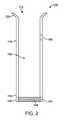
図3は、本開示の様々な実施形態に係る他のサンプルバイアルフィルターインサートの側面図である。フィルターインサート300は、円筒形本体310及びフィルターアッセンブリ340を含む。円筒形本体310は、近位側に開口端部312と、遠位側に端部316と、円筒形本体310の近位側端部312から半径方向に延びる突起又はテーパ状リップ部320とを含む。リップ部320は、サンプルバイアルの開口端部に配備されるように構成される。フィルターアッセンブリ340は、円筒形本体310の遠位側端部316に結合される。キャビティ(図示せず)は、近位側端部312から遠位側端部316まで、円筒形本体310を通って長手方向に延びる。貫通穴360により、キャビティと、フィルターインサート300の外部環境との間の流体連通が可能になる。 FIG. 3 is a side view of another sample vial filter insert according to various embodiments of the present disclosure. The
図1及び図2に示されるフィルターアッセンブリ140は、固体リング142及びディスク又はウエハー形状のフィルター材料144を有するものとして記載される。フィルターインサート100において、サンプル含有溶液は、フィルター材料144が配置されたフィルターインサート100の底部で、前記フィルター材料144を通過することができる。フィルターアッセンブリ340は、複数の細孔344を含み、この孔は、長手方向寸法、すなわち高さが、フィルターアッセンブリ140よりも大きい。また、フィルターアッセンブリ340は、フィルターアッセンブリ340の側壁及び底部に細孔344を有することができる。それゆえ、フィルターアッセンブリ340は、サンプル含有溶液が通過してフィルターインサート300のキャビティに入ることができる表面積は、フィルターインサート100よりも大きい。幾つかの例では、フィルターアッセンブリ340の底部に細孔は無くてもよい。幾つかの例において、フィルターアッセンブリ340は、全体を通して実質的に均一な物理的構造を有する。幾つかの例では、フィルターアッセンブリ340は、底部が多孔質、側壁が多孔質であり、キャビティ(図示せず)が多孔質の底部から円筒形本体310のキャビティまで延びている。幾つかの例において、フィルターアッセンブリ340は、底部に細孔が無く、側壁が多孔質であり、キャビティ(図示せず)が細孔の無い底部から円筒形本体310のキャビティまで延びている。 The
幾つかの例において、フィルターアッセンブリ340は、例えば、図5〜図9に示される実施形態のように、可逆結合によって円筒形本体310の遠位側端部316に結合されることができる。他の例では、フィルターアッセンブリ340を円筒形本体310の遠位側端部316に融着又は溶融することにより、フィルターアッセンブリ340は、円筒形本体310の遠位側端部316に永久的に結合されることができる。さらに幾つかの実施例において、広範囲の化学的環境、温度及び圧力において実質的に安定な固着剤又は接着剤を使用して、円筒形本体310の遠位側端部316に結合されることができる。 In some examples, the
幾つかの例において、フィルターアッセンブリ340は複数の細孔344を含むことができ、各細孔344は実質的に同じ直径を有する。幾つかの例において、フィルターアッセンブリ340は、ある範囲の孔径を有する細孔344を含むことができる。細孔344の各々は、直径が約5ナノメートル(nm)乃至約100マイクロメートル(μm)、あるいは約100nm乃至約50μm、あるいは約250nm乃至約20μm、あるいは約500nm乃至約10μm、あるいは約1μmか乃至約5μmである。 In some examples, the
幾つかの例において、フィルターアッセンブリ340は、織布材料又はメッシュ様材料から作られることができる。また、フィルターアッセンブリ340は、不織布材料であってよく、前記不織布材料は複数の繊維又は規則的に配向された繊維又は不規則に配向された繊維を含む。幾つかの例では、フィルターアッセンブリ340は、疎水性又は親水性材料で作製されることができるし、選択的濾過のために疎水性又は親水性材料でコーティングされることができる。例えば、分析対象の化合物又は組成物が本質的に疎水性である場合、疎水性フィルター材料を使用して、疎水性化合物がフィルターアッセンブリ340を通過できるようにして、親水性化合物の流れが通過するのを防止することができる。フィルターアッセンブリ340は、分析される化学的環境又は組成の種類に基づいて選択又は変更されることができる。 In some examples, the
幾つかの例において、円筒形本体310及びフィルターアッセンブリ340は同じ材料で作られることができる。他の例では、円筒形本体310とフィルターアッセンブリ340とは異なる材料で作られる。 In some examples, the
幾つかの実施例において、円筒形本体310及びフィルターアッセンブリ340のうちの一方又は両方は、ポリマー材料から作られることができる。ポリマー材料は、ポリ(アルキレンオキシド)(例えば、ポリ(エチレンオキシド)、ポリ(プロピレンオキシド)又はポリ(ブチレンオキシド)など)、ポリ(エチレンテレフタレート)、ポリアミン、ポリアミド、ポリイミド、ポリ(アルキルアクリルアミド)、ポリカーボネート(PC)、ポリアクリレート、ポリ(メチルメタクリレート)、ポリビニルアルコール(PVOH)、ポリ酢酸ビニル(PVAc)、ポリ塩化ビニル(PVC)、高密度ポリアルキレン、低密度ポリアルキレン、ポリアラミド、ポリアクリロニトリル(PAN)、芳香族ポリエステル、ポリケトン、ポリアリールエーテルケトン(PAEK)、ポリエーテルエーテルケトン(PEEK)、ポリエーテルケトン(PEKK)、ポリ芳香族、ポリスルホン、及びポリエーテルイミド(PEI)のうちの何れであってもよい。 In some embodiments, one or both of the
他の実施例において、円筒形本体310及びフィルターアッセンブリ340の一方又は両方は、フッ素化ポリマー材料から作られることができる。フッ素化ポリマー材料は、ポリテトラフルオロエチレン、ポリクロロトリフルオロエチレン、ポリエチレンクロロトリフルオロエチレン、ポリフッ化ビニル、ポリフッ化ビニリデン、ペルフルオロアルコキシポリマー、フッ素化エチレン−プロピレンポリマー、ポリエチレンテトラフルオロエチレン、過フッ素化エラストマー、フルオロエラストマー(例えば、テトラフルオロエチレン−プロピレン)、パーフルオロポリエーテル、及びパーフルオロスルホン酸ポリマーのうちの何れであってもよい。 In another embodiment, one or both of the
幾つかの例において、フィルターアッセンブリ340は、炭素系フィルター材料を含むことができ、前記炭素系フィルター材料は、例えば、カーボンナノシート、カーボン繊維、単一壁又は複数壁のカーボンナノチューブ、活性炭、木炭、及び骨炭などが挙げられる。 In some examples, the
幾つかの例において、フィルターアッセンブリ340は、シリコン系フィルター材料を含むことができる。前記シリコン系フィルター材料は、例えば、ポリシロキサン、二酸化ケイ素、ヒュームドシリカ、シリカゲル、エアロゲル、アルミノシリケート、アルカリ土類アルミノシリケート、フルオロシリケートの又はフルオロホウケイ酸塩などが挙げられる。また、フィルターアッセンブリ340は、酸化アルミニウム又は酸化チタンなどの多孔質金属酸化物を含むことができる。 In some examples, the
図4は、本開示の様々な実施形態に係るさらに他のサンプルバイアルフィルターインサートの側面図である。フィルターインサート400は、円筒形本体410及び実質的に球形又は卵形のフィルターアッセンブリ440を含む。円筒形本体410は、近位側に開口端部412と、遠位側に端部416と、円筒形本体410の近位側端部412から半径方向に延びる突起又はテーパ状リップ部420とを含む。リップ部420は、サンプルバイアルの開口端部に配備されるように構成される。フィルターアッセンブリ440は、円筒形本体410の遠位側端部416に結合される。キャビティ(図示せず)は、近位側端部412から遠位側端部416まで、円筒形本体410を通って長手方向に延びる。貫通穴460により、キャビティと、フィルターインサート400の外部環境との間の流体連通が可能になる。フィルターアッセンブリ440は、複数の細孔444を含む。幾つかの例において、フィルターアッセンブリ440は、全体を通して実質的に均一な物理的構造を有する。幾つかの例において、フィルターアッセンブリ440は、実質的に球形又は卵形の多孔質外壁と、前記多孔質外壁から、円筒形本体410のキャビティまで延びるキャビティ(図示せず)とを有する。 FIG. 4 is a side view of yet another sample vial filter insert according to various embodiments of the present disclosure. The
幾つかの例において、フィルターアッセンブリ440は、例えば、図5〜図9に示される実施形態のように、可逆結合によって円筒形本体410の遠位側端部416に結合されることができる。他の例では、フィルターアッセンブリ440を円筒形本体410の遠位側端部416に融着又は溶融することにより、フィルターアッセンブリ440は、円筒形本体410の遠位側端部416に永久的に結合されることができる。さらに幾つかの実施例において、広範囲の化学的環境、温度及び圧力において実質的に安定な固着剤又は接着剤を使用して、円筒形本体410の遠位側端部416に結合されることができる。 In some examples, the
幾つかの例において、フィルターアッセンブリ440は複数の細孔444を含むことができ、各細孔444は実質的に同じ直径を有する。幾つかの例において、フィルターアッセンブリ440は、ある範囲の孔径を有する細孔444を含むことができる。細孔444の各々は、直径が約5ナノメートル(nm)乃至約100マイクロメートル(μm)、あるいは約100nm乃至約50μm、あるいは約250nm乃至約20μm、あるいは約500nm乃至約10μm、あるいは約1μmか乃至約5μmである。 In some examples, the
幾つかの例において、フィルターアッセンブリ440は、織布材料又はメッシュ様材料から作られることができる。また、フィルターアッセンブリ440は、不織布材料であってよく、前記不織布材料は複数の繊維又は規則的に配向された繊維又は不規則に配向された繊維を含む。幾つかの例では、フィルターアッセンブリ440は、疎水性又は親水性材料で作製されることができるし、選択的濾過のために疎水性又は親水性材料でコーティングされることができる。例えば、分析対象の化合物又は組成物が本質的に疎水性である場合、疎水性フィルター材料を使用して、疎水性化合物がフィルターアッセンブリ440を通過できるようにして、親水性化合物の流れが通過するのを防止することができる。フィルターアッセンブリ440は、分析される化学的環境又は組成の種類に基づいて選択又は変更されることができる。 In some examples, the
幾つかの例において、円筒形本体410及びフィルターアッセンブリ440は同じ材料で作られることができる。他の例では、円筒形本体410とフィルターアッセンブリ440とは異なる材料で作られる。 In some examples, the
幾つかの実施例において、円筒形本体410及びフィルターアッセンブリ440のうちの一方又は両方は、ポリマー材料から作られることができる。ポリマー材料は、ポリ(アルキレンオキシド)(例えば、ポリ(エチレンオキシド)、ポリ(プロピレンオキシド)又はポリ(ブチレンオキシド)など)、ポリ(エチレンテレフタレート)、ポリアミン、ポリアミド、ポリイミド、ポリ(アルキルアクリルアミド)、ポリカーボネート(PC)、ポリアクリレート、ポリ(メチルメタクリレート)、ポリビニルアルコール(PVOH)、ポリ酢酸ビニル(PVAc)、ポリ塩化ビニル(PVC)、高密度ポリアルキレン、低密度ポリアルキレン、ポリアラミド、ポリアクリロニトリル(PAN)、芳香族ポリエステル、ポリケトン、ポリアリールエーテルケトン(PAEK)、ポリエーテルエーテルケトン(PEEK)、ポリエーテルケトン(PEKK)、ポリ芳香族、ポリスルホン、及びポリエーテルイミド(PEI)のうちの何れであってもよい。 In some embodiments, one or both of the
他の実施例において、円筒形本体410及びフィルターアッセンブリ440の一方又は両方は、フッ素化ポリマー材料から作られることができる。フッ素化ポリマー材料は、ポリテトラフルオロエチレン、ポリクロロトリフルオロエチレン、ポリエチレンクロロトリフルオロエチレン、ポリフッ化ビニル、ポリフッ化ビニリデン、ペルフルオロアルコキシポリマー、フッ素化エチレン−プロピレンポリマー、ポリエチレンテトラフルオロエチレン、過フッ素化エラストマー、フルオロエラストマー(例えば、テトラフルオロエチレン−プロピレン)、パーフルオロポリエーテル、及びパーフルオロスルホン酸ポリマーのうちの何れであってもよい。 In another embodiment, one or both of the
幾つかの例において、フィルターアッセンブリ440は、炭素系フィルター材料を含むことができ、前記炭素系フィルター材料は、例えば、カーボンナノシート、カーボン繊維、単一壁又は複数壁のカーボンナノチューブ、活性炭、木炭、及び骨炭などが挙げられる。 In some examples, the
幾つかの例において、フィルターアッセンブリ440は、シリコン系フィルター材料を含むことができる。前記シリコン系フィルター材料は、例えば、ポリシロキサン、二酸化ケイ素、ヒュームドシリカ、シリカゲル、エアロゲル、アルミノシリケート、アルカリ土類アルミノシリケート、フルオロシリケートの又はフルオロホウケイ酸塩などが挙げられる。また、フィルターアッセンブリ440は、酸化アルミニウム又は酸化チタンなどの多孔質金属酸化物を含むことができる。 In some examples, the
図5は、本開示の様々な実施形態に係るさらに他のサンプルバイアルフィルターインサートの分解断面図である。フィルターインサート500は、円筒形本体510及びフィルターアッセンブリ540を含む。円筒形本体510は、近位側に開口端部512と、遠位側に半径方向外向きの雄ネジ516を有する開口端部514と、円筒形本体510の近位側端部512から半径方向に延びる突起又はテーパ状リップ部520とを含む。リップ部520は、サンプルバイアルの開口端部に配備されるように構成される。キャビティ550は、近位側端部512から遠位側端部514まで、円筒形本体510を通って長手方向に延びる。貫通穴560により、キャビティ550と、フィルターインサート500の外部環境との間の流体連通が可能になる。フィルターアッセンブリ540は、雌ネジ546を有する円筒形リング544と、フィルター材料542とを含む。フィルターアッセンブリ540は、雄ネジ516と雌ネジ546との螺合により、円筒形本体510の遠位側端部514に結合可能である。 FIG. 5 is an exploded cross-sectional view of yet another sample vial filter insert according to various embodiments of the present disclosure. The
幾つかの例において、円筒形本体510、リング544、及びフィルター材料542は同じ材料から作られることができる。他の例では、円筒形本体510とリング544は同じ材料から作られ、フィルター材料542は異なる材料から作られることができる。他の例において、円筒形本体510は第1の材料から作られ、リング544及びフィルター材料542は第2の材料から作られることができる。さらに他の例では、円筒形本体510、リング544、及びフィルター材料542は全て異なる材料から作られることができる。円筒形本体510、リング544及びフィルター材料542が作られる材料は、円筒形本体110、リング142及びフィルター材料144に関して説明したように作られることができる。 In some examples, the
図6は、本開示の様々な実施形態に係るさらに他のサンプルバイアルフィルターインサートの分解断面図である。フィルターインサート600は、円筒形本体610及びフィルターアッセンブリ640を含む。円筒形本体610は、近位側に開口端部612と、遠位側の周囲及び一部の周りに凹部616を有する開口端部614と、円筒形本体610の近位側端部612から半径方向に延びる突起又はテーパ状リップ部620とを含む。リップ部620は、サンプルバイアルの開口端部に配備されるように構成される。キャビティ650は、近位側端部612から遠位側端部614まで、円筒形本体610を通って長手方向に延びる。貫通穴660により、キャビティ650と、フィルターインサート600の外部環境との間の流体連通が可能になる。フィルターアッセンブリ640は、内面の全部又は一部の周りに形成された突起646を有する円筒形リング644と、フィルター材料642とを含む。突起646の寸法は、凹部616と同じであるか又は実質的に同じである。フィルターアッセンブリ640は、突起646と凹部616とのスナップ嵌合により、円筒形本体610の遠位側端部614に結合可能である。 FIG. 6 is an exploded cross-sectional view of yet another sample vial filter insert according to various embodiments of the present disclosure. The
幾つかの例において、円筒形本体610、リング644、及びフィルター材料642は同じ材料から作られることができる。他の例では、円筒形本体610とリング644は同じ材料から作られ、フィルター材料642は異なる材料から作られることができる。他の例において、円筒形本体610は第1の材料から作られ、リング644及びフィルター材料642は第2の材料から作られることができる。さらに他の例では、円筒形本体610、リング644、及びフィルター材料642は全て異なる材料から作られることができる。円筒形本体610、リング644及びフィルター材料642が作られる材料は、円筒形本体110、リング142及びフィルター材料144に関して説明したように作られることができる。 In some examples, the
図7は、本開示の様々な実施形態に係るさらに他のサンプルバイアルフィルターインサートの分解断面図である。フィルターインサート700は、円筒形本体710及びフィルターアッセンブリ740を含む。円筒形本体710は、近位側に開口端部712と、遠位側に開口端部714と、円筒形本体710の近位側端部712から半径方向に延びる突起又はテーパ状リップ部720とを含む。リップ部720は、サンプルバイアルの開口端部に配備されるように構成される。遠位側端部714は、内面の全部又は一部の周りに形成された凹部716a、716bと突起718とを含む。キャビティ750は、近位側端部712から遠位側端部714まで、円筒形本体710を通って長手方向に延びる。貫通穴760により、キャビティ750と、フィルターインサート700の外部環境との間の流体連通が可能になる。フィルターアッセンブリ740は、内面の全部又は一部の周りに形成された突起746a、746bと凹部748とを有する円筒形リング744と、フィルター材料742とを含む。突起718の寸法は、凹部748と同じであるか又は実質的に同じであり、凹部716aの寸法は、凹部746aと同じであるか又は実質的に同じである。凹部716bの内径は、突起746bの外径と同じであるか又は実質的に同じであり、突起746bの長手方向寸法又は高さは、突起716bの長手方向寸法又は高さと同じであるか、又は大きいか、又は小さい。フィルターアッセンブリ740は、突起718と凹部748とのスナップ嵌合により、円筒形本体710の遠位側端部714に結合可能である。 FIG. 7 is an exploded cross-sectional view of yet another sample vial filter insert according to various embodiments of the present disclosure. The
幾つかの例において、円筒形本体710、リング744、及びフィルター材料742は同じ材料から作られることができる。他の例では、円筒形本体710とリング744は同じ材料から作られ、フィルター材料742は異なる材料から作られることができる。他の例において、円筒形本体710は第1の材料から作られ、リング744及びフィルター材料742は第2の材料から作られることができる。さらに他の例では、円筒形本体710、リング744、及びフィルター材料742は全て異なる材料から作られることができる。円筒形本体710、リング744及びフィルター材料742が作られる材料は、円筒形本体110、リング142及びフィルター材料144に関して説明したように作られることができる。 In some examples, the
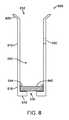
図8は、本開示の様々な実施形態に係るさらに他のサンプルバイアルフィルターインサートの分解断面図である。フィルターインサート800は、円筒形本体810及びフィルター材料840を含む。円筒形本体810は、近位側に開口端部812と、遠位側に端部816と、円筒形本体810の近位側端部812から半径方向に延びる突起又はテーパ状リップ部820とを含む。リップ部820は、サンプルバイアルの開口端部に配備されるように構成される。キャビティ850は、近位側端部812から遠位側端部816まで、円筒形本体810を通って長手方向に延びる。貫通穴860により、キャビティ850と、フィルターインサート800の外部環境との間の流体連通が可能になる。遠位側端部816は、円筒形本体810からキャビティ850の中心に向けて直交する方向に延びるフィルター支持体818を含む。フィルター支持体818の貫通穴830により、サンプル含有溶液は、遠位側端部816を通り、フィルター材料840へ、そしてキャビティ850の中へ進入することができる。フィルター材料840の直径は、キャビティ850の直径と同じであるか又は実質的に同じであり、近位側端部812を通じて円筒形本体810の中へ挿入されることができ、フィルター支持体818に載置される。フィルター材料840は、Oリング844又は同様な固定手段によりフィルター支持体818にさらに固定されることができる。 FIG. 8 is an exploded cross-sectional view of yet another sample vial filter insert according to various embodiments of the present disclosure. The
幾つかの例において、円筒形本体810、フィルター材料840、及びOリング844は同じ材料から作られることができる。他の例では、円筒形本体810とOリング844は同じ材料から作られ、フィルター材料840は異なる材料から作られることができる。他の例において、円筒形本体810は第1の材料から作られ、Oリング844及びフィルター材料840は第2の材料から作られることができる。さらに他の例では、円筒形本体810、フィルター材料840及びOリング844は全て異なる材料から作られることができる。円筒形本体810、フィルター材料840及びOリング844が作られる材料は、円筒形本体110及びフィルター材料144に関して説明したように作られることができる。 In some examples, the
図9は、本開示の様々な実施形態に係るさらに他のサンプルバイアルフィルターインサートの分解断面図である。フィルターインサート900は、円筒形本体910及びフィルター材料940を含む。円筒形本体910は、近位側に開口端部912と、遠位側に端部916と、円筒形本体910の近位側端部912から半径方向に延びる突起又はテーパ状リップ部920とを含む。リップ部920は、サンプルバイアルの開口端部に配備されるように構成される。キャビティ950は、近位側端部912から遠位側端部916まで、円筒形本体910を通って長手方向に延びる。貫通穴960により、キャビティ950と、フィルターインサート900の外部環境との間の流体連通が可能になる。遠位側端部916は、凹部918を含む。フィルター材料940の直径は、凹部918の直径と同じであるか又は実質的に同じであり、遠位側端部916を通じて凹部918の中へ挿入されることができ、凹部918に当接する。フィルター材料940は、Oリング944又は同様な固定手段により凹部918にさらに固定されることができる。凹部918の長手方向寸法又は高さは、フィルター材料940及びOリング944の長手方向寸法又は高さの合計より大きいか又は等しくてよい。 FIG. 9 is an exploded cross-sectional view of yet another sample vial filter insert according to the various embodiments of the present disclosure. The
幾つかの例において、円筒形本体910、フィルター材料940、及びOリング944は同じ材料から作られることができる。他の例では、円筒形本体910とOリング944は同じ材料から作られ、フィルター材料940は異なる材料から作られることができる。他の例において、円筒形本体910は第1の材料から作られ、Oリング944及びフィルター材料940は第2の材料から作られることができる。さらに他の例では、円筒形本体910、フィルター材料940及びOリング944は全て異なる材料から作られることができる。円筒形本体910、フィルター材料940及びOリン9844が作られる材料は、円筒形本体110及びフィルター材料144に関して説明したように作られることができる。 In some examples, the
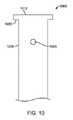
図10は、本開示の様々な実施形態に係るさらに他のサンプルバイアルフィルターインサートの部分側面図である。サンプルフィルターインサート1000は、円筒形本体1010及びフィルター材料(図示せず)を含む。円筒形本体1010は、近位側に開口端部1012と、遠位側に端部(図示せず)と、円筒形本体1010の近位側端部1012から半径方向に延びる非テーパ状リップ部1020とを含む。リップ部920は、サンプルバイアルの開口端部に配備されるように構成される。キャビティ(図示せず)は、近位側端部1012から遠位側端部1016まで、円筒形本体1010を通って長手方向に延びる。貫通穴1060により、キャビティと、フィルターインサート1000の外部環境との間の流体連通が可能になる。遠位側端部とフィルターアッセンブリは、本開示の図1〜図9に示される任意の遠位側端部及びフィルターアッセンブリと同じであるか、実質的に同じであってよい。 FIG. 10 is a partial side view of yet another sample vial filter insert according to various embodiments of the present disclosure. The
本開示の図1〜図9に示されるフィルターインサートは、テーパ状リップ部を有し、図10のフィルターインサートは非テーパ状リップ部を示しており、当業者であれば、フィルターインサートのリップ部は様々な形状のものが、対応するサンプルバイアルに有効に配備され得ることは容易に理解し得るであろう。それゆえ、本開示によるフィルターインサート用のリップの形状は、テーパ状と非テーパ状の構成に特に限定されない。The filter inserts shown in FIGS. 1 to 9 of the present disclosure have a tapered lip portion, and the filter insert of FIG. 10 shows a non-tapered lip portion. It will be easy to see that various shapes can be effectively deployed in the corresponding sample vials. Therefore, the shape of the lip for the filter insert according to the present disclosure is not particularly limited to the tapered and non-tapered configurations.
図11は、本開示の様々な実施形態のサンプルバイアルの中に配置された図1のサンプルバイアルフィルターインサートを示す図である。図11において、フィルターインサート100は、サンプルバイアル1100の中に入れられている。サンプルバイアル1100は、主本体1102と、ボトルネック1104と、外側テーパ部1110と、開口した上面1112とを含む。フィルターインサート100の円筒形本体110の外径は、ボトルネック1104の内径よりも小さい。フィルターインサート100のリップ部120の外側寸法は、外側テーパ部1110の内径にほぼ等しく、リップ部120は外側テーパ部1110に均等に載置される。フィルターインサート100の高さは、サンプルバイアル1100の高さの約40%〜約95%の範囲であってよい。或いは、フィルターインサート100の高さは、サンプルバイアル1100の高さの約50%〜約90%の範囲であってよい。或いは、フィルターインサート100の高さは、サンプルバイアル1100の高さの約60%〜約85%の範囲であってよい。或いは、フィルターインサート100の高さは、サンプルバイアル1100の高さの約70%〜約80%の範囲であってよい。或いは、フィルターインサート100の高さは、サンプルバイアル1100の高さの約75%〜約80%の範囲であってよい。貫通穴1122とブチルゴムセプタムなどの穿刺可能部材1130とを有するシール又はキャップ1120が、サンプルバイアル1100及びその中の内容物を密封する。キャップ1120は、例えば圧着(crimping)によってサンプルバイアルに密封されることができる。フィルターインサート100を配置し、サンプルバイアル1100をキャップ1120と穿刺可能部材1130で密封する前に、溶媒1140及び固体サンプル1150をサンプルバイアル1100の中に入れることができる。溶媒1140は、溶媒ライン1144を有する。使用時には、溶媒ライン1144は、フィルターインサート100の貫通穴160の下にあるべきである。また、使用時、固体サンプル1150がフィルターアッセンブリ140と直接接触しないように、フィルターインサート100のフィルターアッセンブリ140は、サンプルバイアルの底部から十分な間隔をあけるようにする。 FIG. 11 is a diagram showing a sample vial filter insert of FIG. 1 placed in sample vials of various embodiments of the present disclosure. In FIG. 11, the
固体サンプル1150は特に限定されない。幾つかの例において、固体サンプル1150は、有機化合物を含むことができ、該有機化合物として、例えば、ポリマー、小分子医薬化合物、有機フルオロフォア、爆発性物質(例えば、トリニトロトルエンなど)、麻酔薬、脂肪、ワックス、ステロール、脂溶性ビタミン(ビタミンA、D、E、Kなど)、モノグリセリド、ジグリセリド、トリグリセリド、リン脂質などがある。幾つかの例において、固体サンプル1150は無機化合物又は有機金属化合物を含むことができ、これら化合物として、例えば、有機金属触媒、無機リン光体又はフルオロフォア、金属塩(例えば炭酸カルシウムのマグネシウムなど)、異なる電荷を有する金属カチオンの混合物を有する化合物、単座、二座、三座などの配位子の1つ又は2つ以上と錯体を形成した金属などがある。幾つかの例において、固体サンプル1150は生物学的化合物又は組成物を含むことができ、これら化合物又は組成物として、例えば、血清、RNA、及び/又はDNA、ウイルス、細菌、抗体、抗原、タンパク質、核酸、酵素などがある。 The
図11においてフィルターインサート100が使用される場合、図3〜図10に示されたフィルターインサート100の任意の1つが、図11の説明に関して適用されることができる。さらに、図11において、サンプルバイアル1100の外向きテーパ部1110及び開口した上面1112は滑らかな外面を有し、クリンプ型キャップ1120で密封される。他の例において、サンプルバイアル1100の中に、ボトルネック部を有するか又は有さない本体と、雌ネジ付きキャップに螺合可能な雄ネジとが用いられることができる。なお、当業者であれば、クリンプ型キャップ及び雌ネジ付きキャップは、使用され得る多くの異なる種類のサンプルバイアルキャップの中の2つであり、本開示の主題から逸脱しなければ他の種類のキャップを使用できることは認識し得るであろう。 When the
図12は、図1のサンプルバイアルフィルターインサートが入れられたサンプルバイアルの断面図を示しており、本開示の様々な実施形態に係るフィルターインサートのキャビティの中に抽出部材が配置されている。前述したように、フィルターインサート100は、円筒形本体110とフィルターアッセンブリ140とを含む。円筒形本体110は、近位側に開口端部112と、遠位側に端部116と、円筒形本体110の近位側端部112から半径方向に延びる突起又はテーパ状リップ部120とを含む。フィルターインサート100のリップ部120の外側寸法は、外側テーパ部1110の内径にほぼ等しく、リップ部120は外側テーパ部1110に均等に載置される。フィルターアッセンブリ140は、円筒形本体110の遠位側端部116に結合される。キャビティ150は、近位側端部112から遠位側端部116まで、円筒形本体110を通って長手方向に延びる。フィルターアッセンブリ140は、フィルター材料144を含む。使用時、サンプルバイアル1100は、その中に溶媒1140及び固体サンプル1150を有することができる。溶媒1140は、溶媒ライン1144を有する。貫通穴160により、キャビティ150とサンプルバイアル1100の内部との間で流体連通が可能になる。具体的には、貫通穴160により、キャビティ150とサンプルバイアル1100の内部との間の圧力を平衡にすることができ、溶媒ライン1144がキャビティ150の内側と外側で同じ位置になるので、キャビティ150内側の溶媒ライン1144の上のガスと、サンプルバイアル1100の溶媒ライン1144の上のガスは、キャビティ150とサンプルバイアル1100との間を自由に動くことができる。それゆえ、キャビティ150内では、溶媒ライン1144が、気相152を液相154から分離することができる。固体サンプル1150が溶解するか、又は溶媒1140によって溶解されると、サンプル含有溶液1160が生成され、該溶液は、フィルター材料144の中を通過し、キャビティ150の液相154に進入することができる。例えばシリンジなどの抽出部材1170は、キャップ1120の貫通穴1122及び穿刺可能部材1130を通過してフィルターインサート100のキャビティ150の中に進入することができる。抽出部材1170は、液相154に進入して、分析装置による分析のためにサンプル含有溶液1160を含む分量を抽出できるように作られることができる。 FIG. 12 shows a cross-sectional view of the sample vial containing the sample vial filter insert of FIG. 1, in which the extraction member is arranged in the cavity of the filter insert according to the various embodiments of the present disclosure. As described above, the
分析装置は特に限定されない。具体的には、流体又は溶液の組成を決定することができるものであればどんな分析装置も使用することができる。分析装置は、例えば、ガスクロマトグラフィー(GC)、ガスクロマトグラフィー−質量分析(GC−MS)、エレクトロスプレーイオン化ガスクロマトグラフ(ESI−GC)、ガスクロマトグラフィー−IR分光法(GC−IR)、液体クロマトグラフィー−質量分析(LC−MS)、高速液体クロマトグラフィー(HPLC)、ゲル浸透クロマトグラフィー(GPC)、ゲル浸透クロマトグラフィー−IR分光法(GPC−IR)紫外可視(UV−Vis)分光法、蛍光分光法、燐光分光法、電気泳動、キャピラリー電気泳動(CE)、フローサイトメトリー、誘導結合プラズマ質量分析(ICP−MS)、誘導結合プラズマ発光分析(ICP−OES)、電気分解、サイクリックボルタンメトリー(CV)、原子吸光分析(AAS)、原子発光分光法(AES)、フレーム原子吸光分光法(FLAA)、ポリメラーゼ連鎖反応(PCR)、又はあらゆる他の適当な分析装置が挙げられる。 The analyzer is not particularly limited. Specifically, any analyzer can be used as long as it can determine the composition of the fluid or solution. Analytical instruments include, for example, gas chromatography (GC), gas chromatography-mass analysis (GC-MS), electrospray ionized gas chromatograph (ESI-GC), gas chromatography-IR spectroscopy (GC-IR), liquids. Chromatography-mass analysis (LC-MS), high speed liquid chromatography (HPLC), gel permeation chromatography (GPC), gel permeation chromatography-IR spectroscopy (GPC-IR) ultraviolet visible (UV-Vis) spectroscopy, Fluorescence spectroscopy, phosphorescence spectroscopy, electrophoresis, capillary electrophoresis (CE), flow cytometry, inductively coupled plasma mass analysis (ICP-MS), inductively coupled plasma emission analysis (ICP-OES), electrolysis, cyclic voltammetry (CV), Atomic Absorption Analysis (AAS), Atomic Emission Spectroscopy (AES), Frame Atomic Absorption Spectrometry (FLAA), Inductively Coupled Reaction (PCR), or any other suitable analyzer.
図12にはフィルターインサート100が示されているが、図3〜図10に示されるフィルターインサートの何れか1つを図12以後の説明にも適用されることができる。 Although the
図13は、本開示の様々な実施形態における化学分析用フィルターインサートを使用する方法の概略図である。ブロック1310において、固体サンプル及び溶媒をサンプルバイアルに入れる。ブロック1320では、図1〜図10の何れかに図示及び記載されたフィルターインサートなどのフィルターインサートをサンプルバイアルに装入する。ブロック1330では、図11〜図12において前述した貫通穴及び穿刺可能部材を有するサンプルバイアルを、キャップ、蓋又は他の適当なシール部材で密封する。ブロック1340では、固体サンプルが溶媒の中で溶解するか又は溶解されてサンプル含有溶液が生成され、サンプル含有溶液がフィルターアッセンブリを通過してフィルターインサートのキャビティに入るようにする。ブロック1350では、サンプル含有溶液の所定分量を、シリンジなどの抽出部材を使用してフィルターインサートのキャビティから抽出する。ブロック1360では、抽出部材を用いて、所定分量のサンプル含有溶液を化学分析装置に移す。所定分量は、使用者が手操作により又は自動装置により移すことができる。 FIG. 13 is a schematic diagram of a method of using a filter insert for chemical analysis in various embodiments of the present disclosure. At
幾つかの例において、ブロック1310に磁気攪拌バーを加えることもできる。幾つかの例では、ブロック1340は、サンプル含有溶液を生成するに際し、固体サンプルの溶解を補助するために、固体サンプル及び溶媒を撹拌することをさらに含むことができる。この場合、サンプルバイアルは、磁気攪拌バーに作用する装置又はその近傍に配置して、磁気攪拌バーを動かすことができる。また、幾つかの例では、ブロック1340において、サンプル含有溶液を生成するに際し、固体サンプルの溶解を補助するために、固体サンプル及び溶媒を、撹拌し、振動を与え、超音波処理することを含むことができる。この場合、サンプルバイアルは、撹拌装置、振動装置又は超音波処理装置又はその近傍に配置することができる。幾つかの例では、ブロック1340は、サンプル含有溶液を生成するに際し、固体サンプルの溶解を補助するために、固体サンプル及び溶媒を加熱することを含むことができる。 In some examples, a magnetic agitation bar can also be added to the
本明細書に記載されたどのフィルターインサートについてもキットの一部として配備されることができる。キットは、サンプルバイアルと、セプタムなどの穿刺可能部材を含むキャップ又は蓋と、フィルターインサートとを含み得る。キットは攪拌バーをさらに含むことができる。キットが、図5〜図10の何れかに記載されたフィルターインサートを含む場合。2つ以上のフィルターアッセンブリ又はフィルター材料をキットに配置することができ、各フィルターアッセンブリ/材料は異なる特性を有する。例えば、キットは、3つのフィルターアッセンブリ/材料を具えることができ、第1のフィルターアッセンブリ/材料は約5nm〜500nmの直径を有する細孔を有し、第2のものは約500nm〜5μmの細孔を有し、第3のものは5μm〜100μmの細孔を有する。また、キットは、例えば、各々が略同じ直径又は同じ直径範囲の細孔を有する3つのフィルターアッセンブリ/材料を具えることができ、第1のフィルターアッセンブリ/材料は疎水性材料を含み、第2のものは親水性材料を含み、第3のものは、疎水性ドメイン及び親水性ドメインを有する材料を含む。キットはさらに、該キットのフィルターインサート及び他の構成要素を使用するためのマニュアル又は説明書を具えることができる。他のキットでは、複数のフィルターインサートを具えることができ、前記フィルターインサートは、各々が同じ又は実質的に同じ寸法を有するが、異なる溶媒又は溶媒系、温度などの異なる条件で使用するために異なるフィルター材料で作られる。サンプルバイアルは、対応するネジ付きキャップと連結できるネジ付きバイアル、クリンプキャップと共に使用できるバイアルの他、適当なアンプルバイアル及びそれに対応するキャップ又は蓋及び穿刺可能部材であり得る。 Any filter insert described herein can be deployed as part of the kit. The kit may include a sample vial, a cap or lid containing a punctureable member such as a septum, and a filter insert. The kit can further include a stir bar. When the kit includes the filter insert described in any of FIGS. 5-10. Two or more filter assemblies or filter materials can be placed in the kit, and each filter assembly / material has different properties. For example, the kit can include three filter assemblies / materials, the first filter assembly / material has pores with a diameter of about 5 nm to 500 nm, the second has a diameter of about 500 nm to 5 μm. It has pores, the third having pores of 5 μm to 100 μm. Also, the kit can include, for example, three filter assemblies / materials, each having substantially the same diameter or pores in the same diameter range, the first filter assembly / material comprising a hydrophobic material, the second. The one contains a hydrophilic material, and the third contains a material having a hydrophobic domain and a hydrophilic domain. The kit can also be equipped with manuals or instructions for using the kit's filter inserts and other components. Other kits can include multiple filter inserts, each of which has the same or substantially the same dimensions, but for use in different solvents or solvent systems, different conditions such as temperature. Made of different filter materials. The sample vial can be a suitable ampoule vial and a corresponding cap or lid and punctureable member, as well as a threaded vial that can be connected to the corresponding threaded cap, a vial that can be used with a crimp cap.
本開示は以下の項目の記述を含む。 This disclosure includes a description of the following items:
項目1:サンプルバイアルアッセンブリであって、近位側に開口端部及び遠位側に閉端部を有するサンプルバイアルと;円筒形本体とフィルターアッセンブリを含むフィルターインサートであって、前記円筒形本体が、近位側端部と、前記近位側端部から半径方向に延びて、前記サンプルバイアルの開口端部に配備されるように構成された突起と、遠位側端部と、前記円筒形本体を通り、前記近位側端部から遠位側端部まで長手方向に延びるキャビティとを有し、前記フィルターアッセンブリが前記円筒形本体の遠位側端部に結合された、フィルターインサートと;前記サンプルバイアルの近位側の開口端部に結合されるように構成されたシールと、を具え、サンプル抽出部材が、前記シールの中を通って前記円筒形本体の前記キャビティの中へ進入することができる、サンプルバイアルアッセンブリ。 Item 1: A sample vial assembly with an open end on the proximal side and a closed end on the distal side; a filter insert containing a cylindrical body and a filter assembly, wherein the cylindrical body is , A protrusion configured to extend radially from the proximal end and to be deployed at the open end of the sample vial, a distal end, and the cylindrical shape. With a filter insert having a cavity extending longitudinally from the proximal end to the distal end through the body and the filter assembly coupled to the distal end of the cylindrical body; With a seal configured to be coupled to the proximal open end of the sample vial, the sample extractor enters the cavity of the cylindrical body through the seal. Can be a sample vial assembly.
項目2:前記フィルターインサートの遠位側端部と前記フィルターアッセンブリとが螺合により結合されている、項目1のアッセンブリ。 Item 2: The assembly of item 1 in which the distal end of the filter insert and the filter assembly are screwed together.
項目3:前記フィルターインサートの遠位側端部と前記フィルターアッセンブリとがスナップ嵌合により結合されている、項目1のアッセンブリ。 Item 3: The assembly of item 1 in which the distal end of the filter insert and the filter assembly are coupled by snap fitting.
項目4:前記フィルターインサートの遠位側端部と前記フィルターアッセンブリとが互いに溶着又は接着されている、項目1のアッセンブリ。 Item 4: The assembly of item 1 in which the distal end of the filter insert and the filter assembly are welded or adhered to each other.
項目5:前記フィルターアッセンブリは、メッシュ織物のフィルター材料を含む、項目1乃至4の何れかのアッセンブリ。 Item 5: The assembly according to any one of items 1 to 4, wherein the filter assembly includes a filter material of a mesh woven fabric.
項目6:前記フィルターアッセンブリは、多孔質フィルター材料を含む、項目1乃至5の何れかのアッセンブリ。 Item 6: The assembly according to any one of items 1 to 5, wherein the filter assembly includes a porous filter material.
項目7:前記フィルターアッセンブリは、疎水性フィルター材料を含む、項目1乃至6の何れかのアッセンブリ。 Item 7: The assembly according to any one of items 1 to 6, wherein the filter assembly includes a hydrophobic filter material.
項目8:前記フィルターアッセンブリは、親水性フィルター材料を含む、項目1乃至7の何れかのアッセンブリ。 Item 8: The assembly according to any one of items 1 to 7, wherein the filter assembly includes a hydrophilic filter material.
項目9:前記フィルターインサートの円筒形本体は、前記キャビティと前記サンプルバイアルの内部との間を流体連通させるための貫通穴をさらに含む、項目1乃至8の何れかのアッセンブリ。 Item 9: The assembly of any of items 1-8, wherein the cylindrical body of the filter insert further comprises a through hole for fluid communication between the cavity and the interior of the sample vial.
項目10:前記フィルターインサートの円筒形本体と前記フィルターアッセンブリは、同じ材料から作られている、項目1乃至9の何れかのアッセンブリ。 Item 10: The assembly according to any one of items 1 to 9, wherein the cylindrical body of the filter insert and the filter assembly are made of the same material.
項目11:前記フィルターインサートの円筒形本体と前記フィルターアッセンブリは、異なる材料から作られている、項目1乃至9の何れかのアッセンブリ。 Item 11: The assembly according to any one of items 1 to 9, wherein the cylindrical body of the filter insert and the filter assembly are made of different materials.
項目12:前記フィルターインサートの円筒形本体及び前記フィルターアッセンブリの一方又は両方は、本質的に、ポリマー材料から構成される、項目1乃至11の何れかのアッセンブリ。 Item 12: The assembly of any of items 1 to 11, wherein one or both of the cylindrical body of the filter insert and the filter assembly is essentially composed of a polymeric material.
項目13:前記ポリマー材料は、フッ素化ポリマー材料である、項目12のアッセンブリ。 Item 13: The assembly of item 12, wherein the polymer material is a fluorinated polymer material.
項目14:前記フッ素化ポリマー材料は、ポリテトラフルオロエチレン、ポリクロロトリフルオロエチレン、ポリエチレンクロロトリフルオロエチレン、ポリフッ化ビニル、ポリフッ化ビニリデン、ペルフルオロアルコキシポリマー、フッ素化エチレン−プロピレンポリマー、ポリエチレンテトラフルオロエチレン、過フッ素化エラストマー、フルオロエラストマー、パーフルオロポリエーテル、及びパーフルオロスルホン酸ポリマーのうちの何れかである、項目13のアッセンブリ。 Item 14: The fluorinated polymer material is polytetrafluoroethylene, polychlorotrifluoroethylene, polyethylene chlorotrifluoroethylene, polyvinyl fluoride, polyvinylidene fluoride, perfluoroalkoxy polymer, fluorinated ethylene-propylene polymer, polyethylene tetrafluoroethylene. , The assembly of item 13, which is any of a perfluorinated elastomer, a fluoropolymer, a perfluoropolyether, and a perfluorosulfonic acid polymer.
項目15:前記フッ素化ポリマー材料は、ポリテトラフルオロエチレンである、項目14のアッセンブリ。 Item 15: The assembly of item 14, wherein the fluorinated polymer material is polytetrafluoroethylene.
項目16:前記ポリマー材料は、ポリ(アルキレンオキシド)、ポリ(エチレンテレフタレート)、ポリアミン、ポリアミド、ポリイミド、ポリ(アルキルアクリルアミド)、ポリカーボネート、ポリアクリレート、ポリ(メチルメタクリレート)、ポリビニルアルコール、ポリ酢酸ビニル、ポリ塩化ビニル、高密度ポリアルキレン、低密度ポリアルキレン、ポリアラミド、ポリアクリロニトリル、芳香族ポリエステル、ポリケトン、ポリアリールエーテルケトン(PAEK)、ポリエーテルエーテルケトン(PEEK)、ポリエーテルケトン(PEKK)、ポリ芳香族、ポリスルホン、及びポリエーテルイミドのうちの何れかである、項目12のアッセンブリ。 Item 16: The polymer material is poly (alkylene oxide), poly (ethylene terephthalate), polyamine, polyamide, polyimide, poly (alkylacrylamide), polycarbonate, polyacrylate, poly (methylmethacrylate), polyvinyl alcohol, polyvinyl acetate, Polyvinyl chloride, high density polyalkylene, low density polyalkylene, polyaramid, polyacrylonitrile, aromatic polyester, polyketone, polyaryletherketone (PAEK), polyetheretherketone (PEEK), polyetherketone (PEKK), polyaroma The assembly of item 12, which is any of the group, polysulfone, and polyetherimide.
項目17:サンプルバイアルアッセンブリに使用されるフィルターインサートであって、円筒形本体と、フィルターアッセンブリと、を含み、前記円筒形本体が、近位側端部と、前記近位側端部から半径方向に延びて、前記サンプルバイアルの開口端部に配備されるように構成された突起と、遠位側端部と、前記円筒形本体を通り、前記近位側端部から遠位側端部まで長手方向に延びるキャビティとを有し、前記フィルターアッセンブリが前記円筒形本体の遠位側端部に結合されている、フィルターインサート。 Item 17: A filter insert used in a sample vial assembly, comprising a cylindrical body and a filter assembly, wherein the cylindrical body is radially from the proximal end and the proximal end. Through a protrusion configured to be deployed at the open end of the sample vial, a distal end, and the cylindrical body, from the proximal end to the distal end. A filter insert having a cavity extending in the longitudinal direction and having the filter assembly coupled to the distal end of the cylindrical body.
項目18:前記遠位側端部と前記フィルターアッセンブリとが螺合により結合されている、項目17のフィルターインサート。 Item 18: The filter insert of item 17, wherein the distal end and the filter assembly are screwed together.
項目19:前記遠位側端部と前記フィルターアッセンブリとがスナップ嵌合により結合されている、項目17のフィルターインサート。 Item 19: The filter insert of item 17, wherein the distal end and the filter assembly are coupled by snap fitting.
項目20:前記遠位側端部と前記フィルターアッセンブリとが互いに溶着又は接着されている、項目17のフィルターインサート。 Item 20: The filter insert of item 17, wherein the distal end and the filter assembly are welded or adhered to each other.
項目21:前記フィルターアッセンブリは、メッシュ織物のフィルター材料を含む、項目17乃至20の何れかのフィルターインサート。 Item 21: The filter insert according to any one of items 17 to 20, wherein the filter assembly includes a filter material of a mesh fabric.
項目22:前記フィルターアッセンブリは、多孔質フィルター材料を含む、項目17乃至21の何れかのフィルターインサート。 Item 22: The filter insert according to any one of items 17 to 21, wherein the filter assembly comprises a porous filter material.
項目23:前記フィルターアッセンブリは、疎水性フィルター材料を含む、項目17乃至22の何れかのフィルターインサート。 Item 23: The filter insert according to any one of items 17 to 22, wherein the filter assembly comprises a hydrophobic filter material.
項目24:前記フィルターアッセンブリは、親水性フィルター材料を含む、項目17乃至23の何れかのフィルターインサート。 Item 24: The filter insert according to any one of items 17 to 23, wherein the filter assembly comprises a hydrophilic filter material.
項目25:前記円筒形本体は、前記キャビティと前記フィルターインサートの周囲環境との間を流体連通させるための貫通穴をさらに含む、項目17乃至24の何れかのフィルターインサート。 Item 25: The filter insert of any of items 17-24, wherein the cylindrical body further comprises a through hole for fluid communication between the cavity and the ambient environment of the filter insert.
項目26:前記円筒形本体と前記フィルターアッセンブリは、同じ材料から作られている、項目17乃至25の何れかのフィルターインサート。 Item 26: The filter insert of any of items 17-25, wherein the cylindrical body and the filter assembly are made of the same material.
項目27:前記円筒形本体と前記フィルターアッセンブリは、異なる材料から作られている、項目17乃至25の何れかのフィルターインサート。 Item 27: The filter insert of any of items 17-25, wherein the cylindrical body and the filter assembly are made of different materials.
項目28:前記円筒形本体及び前記フィルターアッセンブリの一方又は両方は、本質的に、ポリマー材料から構成される、項目17乃至27の何れかのフィルターインサート。 Item 28: The filter insert of any of items 17-27, wherein one or both of the cylindrical body and the filter assembly is essentially composed of a polymeric material.
項目29:前記ポリマー材料は、フッ素化ポリマー材料である、項目28のフィルターインサート。 Item 29: The filter insert of item 28, wherein the polymer material is a fluorinated polymer material.
項目30:前記フッ素化ポリマー材料は、ポリテトラフルオロエチレン、ポリクロロトリフルオロエチレン、ポリエチレンクロロトリフルオロエチレン、ポリフッ化ビニル、ポリフッ化ビニリデン、ペルフルオロアルコキシポリマー、フッ素化エチレン−プロピレンポリマー、ポリエチレンテトラフルオロエチレン、過フッ素化エラストマー、フルオロエラストマー、フルオロカーボンポリマー、パーフルオロポリエーテル、及びパーフルオロスルホン酸ポリマーのうちの何れかである、項目29のフィルターインサート。 Item 30: The fluorinated polymer material is polytetrafluoroethylene, polychlorotrifluoroethylene, polyethylene chlorotrifluoroethylene, polyvinyl fluoride, polyvinylidene fluoride, perfluoroalkoxy polymer, fluorinated ethylene-propylene polymer, polyethylene tetrafluoroethylene. , A filter insert of item 29, which is any of a perfluorinated elastomer, a fluoropolymer, a fluorocarbon polymer, a perfluoropolyether, and a perfluorosulfonic acid polymer.
項目31:前記フッ素化ポリマー材料は、ポリテトラフルオロエチレンである、項目30のフィルターインサート。 Item 31: The filter insert of item 30, wherein the fluorinated polymer material is polytetrafluoroethylene.
項目32:前記ポリマー材料は、ポリ(アルキレンオキシド)、ポリ(エチレンテレフタレート)、ポリアミン、ポリアミド、ポリイミド、ポリ(アルキルアクリルアミド)、ポリカーボネート、ポリアクリレート、ポリ(メチルメタクリレート)、ポリビニルアルコール、ポリ酢酸ビニル、ポリ塩化ビニル、高密度ポリアルキレン、低密度ポリアルキレン、ポリアラミド、ポリアクリロニトリル、芳香族ポリエステル、ポリケトン、ポリアリールエーテルケトン(PAEK)、ポリエーテルエーテルケトン(PEEK)、ポリエーテルケトン(PEKK)、ポリ芳香族、ポリスルホン、及びポリエーテルイミドのうちの何れかである、項目29のフィルターインサート。 Item 32: The polymer material is poly (alkylene oxide), poly (ethylene terephthalate), polyamine, polyamide, polyimide, poly (alkylacrylamide), polycarbonate, polyacrylate, poly (methylmethacrylate), polyvinyl alcohol, polyvinyl acetate, Polyvinyl chloride, high density polyalkylene, low density polyalkylene, polyaramid, polyacrylonitrile, aromatic polyester, polyketone, polyaryletherketone (PAEK), polyetheretherketone (PEEK), polyetherketone (PEKK), polyaroma The filter insert of item 29, which is one of the group, polysulfone, and polyetherimide.
項目33:固体サンプルを分析する方法であって、固体サンプル及び溶媒をサンプルバイアルに入れることと、フィルターインサートをサンプルバイアルに配置することであって、前記フィルターインサートが、円筒形本体と、フィルターアッセンブリとを含み、前記円筒形本体が、近位側端部と、前記近位側端部から半径方向に延びて、前記サンプルバイアルの開口端部に配備されるように構成された突起と、遠位側端部と、前記円筒形本体を通り、前記近位側端部から遠位側端部まで長手方向に延びるキャビティとを有し、前記フィルターアッセンブリが前記円筒形本体の遠位側端部に結合されている、前記配置することと、前記サンプルバイアルをシールで密封することであって、前記シールが、サンプル部材が前記円筒形本体のキャビティの中へ進入できるように前記サンプル抽出部材の通過を許容するよう構成されている、前記密封することと、前記固体サンプルを溶媒の中で溶解させて、サンプル含有溶液を生成することと、前記サンプル含有溶液が前記フィルターアッセンブリを通過して前記円筒形本体のキャビティに進入させることと、前記サンプル含有溶液の所定分量を、前記円筒形本体のキャビティから抽出することと、前記所定分量を化学分析装置に移すことと、を含む、方法。 Item 33: A method of analyzing a solid sample, in which the solid sample and solvent are placed in a sample vial and the filter insert is placed in a sample vial, wherein the filter insert has a cylindrical body and a filter assembly. And a protrusion configured such that the cylindrical body extends radially from the proximal end and is deployed at the open end of the sample vial. It has a position-side end and a cavity that passes through the cylindrical body and extends longitudinally from the proximal-side end to the distal-side end, and the filter assembly is the distal-side end of the cylindrical body. The placement of the sample vial and the sealing of the sample vial, which is coupled to the sample extraction member, allows the sample member to enter the cavity of the cylindrical body. The sealing, which is configured to allow passage, the solid sample is dissolved in a solvent to produce a sample-containing solution, and the sample-containing solution passes through the filter assembly. A method comprising entering a cavity of a cylindrical body, extracting a predetermined amount of the sample-containing solution from the cavity of the cylindrical body, and transferring the predetermined amount to a chemical analyzer.
項目34:固体サンプルを溶媒に溶解させることが、固体サンプル及び溶媒を撹拌することをさらに含む、項目33の方法。 Item 34: The method of item 33, wherein dissolving the solid sample in a solvent further comprises stirring the solid sample and the solvent.
項目35:固体サンプルを溶媒に溶解させることが、固体サンプル及び溶媒を撹拌すること、振動を与えること、及び超音波処理することをさらに含む、項目33又は項目34の方法。 Item 35: The method of item 33 or item 34, wherein dissolving the solid sample in a solvent further comprises stirring the solid sample and the solvent, applying vibrations, and sonicating.
項目36:固体サンプルを溶媒に溶解させることが、固体サンプル及び溶媒を加熱することをさらに含む、項目33乃至35の何れかの方法。 Item 36: The method of any of items 33-35, wherein dissolving the solid sample in a solvent further comprises heating the solid sample and the solvent.
項目37:固体サンプルは有機組成物を含む、項目33乃至36の何れかの方法。 Item 37: The method of any of items 33-36, wherein the solid sample comprises an organic composition.
項目38:サンプルは無機組成物を含む、項目33乃至37の何れかの方法。 Item 38: The method of any of items 33-37, wherein the sample comprises an inorganic composition.
項目39:サンプルは有機金属組成物を含む、項目33乃至38の何れかの方法。 Item 39: The method of any of items 33-38, wherein the sample comprises an organometallic composition.
項目40:サンプルは生物学的組成物を含む、項目33乃至39の何れかの方法。 Item 40: The method of any of items 33-39, wherein the sample comprises a biological composition.
項目41:サンプルバイアルと、前記サンプルバイアルの中に配置されることができるフィルターインサートと、前記サンプルバイアルを密封するシール部材と、を含むキットであって、前記フィルターインサートが、円筒形本体と、フィルターアッセンブリとを含み、前記円筒形本体が、近位側端部と、前記近位側端部から半径方向に延びて、前記サンプルバイアルの開口端部に配備されるように構成された突起と、遠位側端部と、前記円筒形本体を通り、前記近位側端部から遠位側端部まで長手方向に延びるキャビティとを有し、前記フィルターアッセンブリが前記円筒形本体の遠位側端部に結合されており、前記シール部材が、サンプルバイアルに結合され、サンプル抽出部材がシール部材を通って円筒形本体のキャビティ内に通過することができるように構成されている、キット。 Item 41: A kit comprising a sample vial, a filter insert that can be placed in the sample vial, and a sealing member that seals the sample vial, wherein the filter insert is a cylindrical body. With a projection that includes a filter assembly and the cylindrical body is configured to extend radially from the proximal end and the open end of the sample vial. Has a distal end and a cavity extending longitudinally from the proximal end to the distal end through the cylindrical body, the filter assembly being distal to the cylindrical body. A kit that is attached to the end so that the sealing member is attached to the sample vial and the sample extraction member can pass through the sealing member into the cavity of the cylindrical body.
項目42:磁気撹拌バーをさらに含む、項目41のキット。 Item 42: Kit of item 41, further comprising a magnetic agitation bar.
項目43:1つ又は複数の追加のフィルターアッセンブリをさらに含む、項目41又は項目42のキット。 Item 43: The kit of item 41 or item 42, further comprising one or more additional filter assemblies.
項目44:フィルターアッセンブリ及び1つ又は複数の追加のフィルターアッセンブリは各々が異なるフィルター材料を含む、項目43のキット。 Item 44: The kit of item 43, wherein the filter assembly and one or more additional filter assemblies each contain a different filter material.
項目45:異なるフィルター材料は各々が、所定の直径又は直径範囲の細孔を含む、項目44のキット。 Item 45: The kit of item 44, wherein the different filter materials each contain pores of a predetermined diameter or range of diameters.
項目46:異なるフィルター材料は、疎水性フィルター材料及び親水性フィルター材料のうちの1つ又は2つを含む、項目44又は項目45に記載のキット。 Item 46: The kit of item 44 or item 45, wherein the different filter material comprises one or two of a hydrophobic filter material and a hydrophilic filter material.
項目47:シール部材がセプタム及びクリンプ式キャップを含む、項目41乃至46の何れかのキット。 Item 47: The kit of any of items 41-46, wherein the sealing member comprises a septum and a crimp cap.
項目48:サンプルバイアルの近位側開口端部が、シール部材と結合するための雄ネジ部をさらに含む、項目41乃至47の何れかのキット。 Item 48: The kit of any of items 41-47, wherein the proximal open end of the sample vial further comprises a male thread for coupling with a sealing member.
項目49:サンプルバイアルのシール部材は、サンプルバイアルの雄ネジ部と結合するためのセプタム及び雌ネジ部を含む、項目48のキット。 Item 49: The kit of item 48, wherein the seal member of the sample vial comprises a septum and a female thread portion for connecting to the male threaded portion of the sample vial.
図示及び上記した実施形態は単なる実施例である。したがって、その詳細の多くは図示も記載もされていない。本発明の多くの特徴及び利点について、本開示の構造及び機能の詳細と共に記載されているが、それらの本開示は例示にすぎず、その詳細について、特に本開示の原理内にある部品の形状、サイズ及び配置については、添付の特許請求の範囲で使用される用語の広範で一般的な意味によって表される程度にまで変更を加えることができる。それゆえ、上記の実施形態は添付の特許請求の範囲内で修正され得ることは理解されるべきである。 The illustrated and above embodiments are merely embodiments. Therefore, many of the details are neither illustrated nor described. Although many features and advantages of the present invention have been described with details of the structure and function of the present disclosure, these disclosures are merely exemplary and the details are particularly in the form of parts within the principles of the present disclosure. , Size and arrangement may be modified to the extent represented by the broad and general meaning of the terms used in the appended claims. Therefore, it should be understood that the above embodiments may be modified within the appended claims.
Claims (16)
Translated fromJapanese近位側に開口端部及び遠位側に閉端部を有するサンプルバイアルと、
円筒形本体及びフィルターアッセンブリを含むフィルターインサートであって、前記円筒形本体が、近位側端部と、前記近位側端部から半径方向に延びて、前記サンプルバイアルの開口端部に配備されるように構成された突起と、遠位側端部と、前記円筒形本体を通り、前記近位側端部から前記遠位側端部まで長手方向に延びるキャビティとを有し、前記フィルターアッセンブリが前記円筒形本体の前記遠位側端部に結合されている、フィルターインサートと、
前記サンプルバイアルの近位側の開口端部に結合されるように構成されたシールと、を具え、
サンプル抽出部材が、前記シールの中を通って前記円筒形本体の前記キャビティの中へ進入することができるように構成され、
前記フィルターインサートの前記突起が、前記サンプルバイアルの前記近位側開口端部にセットされたとき、前記フィルターインサートが前記サンプルバイアルの前記遠位側閉端部に接触しないように、前記フィルターインサートの高さが前記サンプルバイアルの高さよりも低い、サンプルバイアルアッセンブリ。It is a sample vial assembly
A sample vial with an open end on the proximal side and a closed end on the distal side,
A filter insert that includes a cylindrical body and a filter assembly, wherein the cylindrical body extends radially from the proximal end and the proximal end and is deployed at the open end of the sample vial. The filter assembly has a protrusion configured to be such, a distal end, and a cavity extending longitudinally from the proximal end to the distal end through the cylindrical body. With the filter insert, which is coupled to the distal end of the cylindrical body,
With a seal configured to be attached to the proximal end of the sample vial.
The sample extraction member is configured to be able to enter the cavity of the cylindrical body through the seal.
When the protrusion of the filter insert is set on the proximal open end of the sample vial, the filter insert prevents the filter insert from contacting the distal closed end of the sample vial. A sample vial assembly whose height is lower than the height of the sample vial.
Applications Claiming Priority (3)
| Application Number | Priority Date | Filing Date | Title |
|---|---|---|---|
| US201662431737P | 2016-12-08 | 2016-12-08 | |
| US62/431,737 | 2016-12-08 | ||
| PCT/US2017/065100WO2018106909A1 (en) | 2016-12-08 | 2017-12-07 | Filter insert and sample vial using the same |
Publications (2)
| Publication Number | Publication Date |
|---|---|
| JP2020514756A JP2020514756A (en) | 2020-05-21 |
| JP6968453B2true JP6968453B2 (en) | 2021-11-17 |
Family
ID=62491353
Family Applications (1)
| Application Number | Title | Priority Date | Filing Date |
|---|---|---|---|
| JP2019551500AActiveJP6968453B2 (en) | 2016-12-08 | 2017-12-07 | Filter insert and sample vial using the filter insert |
Country Status (5)
| Country | Link |
|---|---|
| US (3) | US11623167B2 (en) |
| EP (1) | EP3551312A4 (en) |
| JP (1) | JP6968453B2 (en) |
| CN (1) | CN212881367U (en) |
| WO (1) | WO2018106909A1 (en) |
Families Citing this family (2)
| Publication number | Priority date | Publication date | Assignee | Title |
|---|---|---|---|---|
| CN110691975B (en)* | 2017-06-02 | 2024-02-02 | 株式会社日立高新技术 | Automatic analysis device and analysis method |
| WO2024227129A1 (en)* | 2023-04-28 | 2024-10-31 | Gentueri Inc. | Separation basket |
Family Cites Families (27)
| Publication number | Priority date | Publication date | Assignee | Title |
|---|---|---|---|---|
| ES8801129A1 (en) | 1984-07-05 | 1987-12-16 | Nelson Jerald C | Dialysis cell |
| ATE98770T1 (en)* | 1984-07-05 | 1994-01-15 | Jerald C Nelson | DIALYSIS CELL. |
| US5556541A (en)* | 1994-04-26 | 1996-09-17 | Filtertek, Inc. | Process for making hermetically sealed filter units and filters made thereby |
| US5601711A (en)* | 1994-10-31 | 1997-02-11 | Gelman Sciences Inc. | Selective separation filter device |
| US6232417B1 (en)* | 1996-03-07 | 2001-05-15 | The B. F. Goodrich Company | Photoresist compositions comprising polycyclic polymers with acid labile pendant groups |
| DE19729028C1 (en)* | 1997-07-08 | 1999-05-06 | Fraunhofer Ges Forschung | Device and method for isolating cell material from a tissue association and / or a liquid |
| US6506167B1 (en)* | 1997-12-24 | 2003-01-14 | I-Design Co., Ltd. | Blood-collecting tubes |
| JP3015854B2 (en)* | 1997-12-24 | 2000-03-06 | 株式会社アイ・デザイン | Blood collection tube |
| WO2002043841A2 (en)* | 2000-12-01 | 2002-06-06 | Millipore Corporation | Chemical process system with multi-functional barrier filter |
| US7556733B2 (en)* | 2001-06-15 | 2009-07-07 | Mds Analytical Technologies (Us) Inc. | Low volume filtration column devices and methods of filtering therewith |
| US20030013205A1 (en)* | 2001-07-06 | 2003-01-16 | Franz Konrad | Separating device |
| US7211037B2 (en)* | 2002-03-04 | 2007-05-01 | Therakos, Inc. | Apparatus for the continuous separation of biological fluids into components and method of using same |
| US7479123B2 (en)* | 2002-03-04 | 2009-01-20 | Therakos, Inc. | Method for collecting a desired blood component and performing a photopheresis treatment |
| JP2003329688A (en)* | 2002-05-10 | 2003-11-19 | Fujirebio Inc | Cap, reagent container having the cap, and method for preventing evaporation of reagent using the cap |
| DE10240787B4 (en)* | 2002-08-30 | 2004-07-22 | Oxyphen Ag | Cell culture insert |
| DE20218503U1 (en)* | 2002-11-28 | 2003-03-06 | Macherey, Nagel GmbH & Co. Handelsgesellschaft, 52355 Düren | Separation device for the treatment of biomolecules |
| JP2005283356A (en)* | 2004-03-30 | 2005-10-13 | Sumitomo Metal Mining Co Ltd | Method, mechanism and apparatus for centrifugal filtration of soil content investigation test solution |
| DE102006021404A1 (en) | 2006-05-08 | 2007-11-15 | Roche Diagnostics Gmbh | Liquid container with removal chimney |
| JP5057740B2 (en)* | 2006-10-06 | 2012-10-24 | 中国電力株式会社 | Radiation balance meter |
| EP2379227B1 (en)* | 2008-12-31 | 2014-01-22 | 3M Innovative Properties Company | Methods for isolating microorganisms |
| JP5242537B2 (en)* | 2009-11-06 | 2013-07-24 | 株式会社日立ハイテクノロジーズ | Reagent container and reagent container tube |
| JP5549284B2 (en)* | 2010-03-09 | 2014-07-16 | 株式会社島津製作所 | Autosampler |
| JP5039171B2 (en) | 2010-05-11 | 2012-10-03 | 三菱電機株式会社 | Electric drive device and electric power steering device equipped with the electric drive device |
| EP2654957B1 (en)* | 2010-12-21 | 2019-07-17 | GE Healthcare UK Limited | Filtration apparatus |
| US8322539B1 (en) | 2012-03-02 | 2012-12-04 | Scientific Plastic Products, Inc. | Filter vial |
| US20150231536A1 (en)* | 2012-10-22 | 2015-08-20 | Panasonic Intellectual Property Management Co., Ltd. | Filter device |
| US9677981B2 (en)* | 2013-03-15 | 2017-06-13 | 3M Innovative Properties Company | Sample concentrator and method of use |
- 2017
- 2017-12-07JPJP2019551500Apatent/JP6968453B2/enactiveActive
- 2017-12-07WOPCT/US2017/065100patent/WO2018106909A1/ennot_activeCeased
- 2017-12-07USUS16/466,969patent/US11623167B2/enactiveActive
- 2017-12-07EPEP17878672.9Apatent/EP3551312A4/enactivePending
- 2017-12-07CNCN201790001489.1Upatent/CN212881367U/enactiveActive
- 2023
- 2023-03-20USUS18/123,492patent/US12263422B2/enactiveActive
- 2025
- 2025-03-31USUS19/095,867patent/US20250222377A1/enactivePending
Also Published As
| Publication number | Publication date |
|---|---|
| US12263422B2 (en) | 2025-04-01 |
| EP3551312A1 (en) | 2019-10-16 |
| WO2018106909A1 (en) | 2018-06-14 |
| EP3551312A4 (en) | 2020-08-05 |
| JP2020514756A (en) | 2020-05-21 |
| CN212881367U (en) | 2021-04-06 |
| US20250222377A1 (en) | 2025-07-10 |
| US20230226469A1 (en) | 2023-07-20 |
| US11623167B2 (en) | 2023-04-11 |
| US20190336891A1 (en) | 2019-11-07 |
Similar Documents
| Publication | Publication Date | Title |
|---|---|---|
| US20250222377A1 (en) | Filter insert and sample vial using the same | |
| JP6735276B2 (en) | System and method for collecting nucleic acid samples | |
| JP6434207B2 (en) | Magnetic rack system and method of use thereof | |
| CN108601565B (en) | Sample container and method for separating serum or plasma from whole blood | |
| EP2906924B1 (en) | Apparatus and method for analyte extraction | |
| WO2018026886A1 (en) | Automated protein precipitation and/or dispersive solid phase extraction using filter tips | |
| US20040245163A1 (en) | Purification device for ribonucleic acid in large volumes, and method | |
| JP5954532B2 (en) | Nucleic acid extraction device, nucleic acid extraction kit, nucleic acid extraction apparatus and nucleic acid extraction method | |
| EP3074131B1 (en) | Transportable composite liquid cells | |
| JP6011036B2 (en) | device | |
| WO2021046110A1 (en) | Automated group separations of complex mixtures with gel filtration pipette tips | |
| CN113631270B (en) | Sample container for sample pretreatment | |
| US20150375223A1 (en) | Disposable Tip for pricking septum of a sample vial for sample preparation and/or analysis. | |
| EP4477311A1 (en) | Chromatography devices and methods | |
| US20120217203A1 (en) | Self-contained dialysis system | |
| BR102013025451A2 (en) | detachable extraction microdevice for adaptation to removable needle microsyres |
Legal Events
| Date | Code | Title | Description |
|---|---|---|---|
| A621 | Written request for application examination | Free format text:JAPANESE INTERMEDIATE CODE: A621 Effective date:20190909 | |
| A977 | Report on retrieval | Free format text:JAPANESE INTERMEDIATE CODE: A971007 Effective date:20200930 | |
| A131 | Notification of reasons for refusal | Free format text:JAPANESE INTERMEDIATE CODE: A131 Effective date:20201006 | |
| A601 | Written request for extension of time | Free format text:JAPANESE INTERMEDIATE CODE: A601 Effective date:20210105 | |
| A521 | Request for written amendment filed | Free format text:JAPANESE INTERMEDIATE CODE: A523 Effective date:20210222 | |
| A131 | Notification of reasons for refusal | Free format text:JAPANESE INTERMEDIATE CODE: A131 Effective date:20210330 | |
| A601 | Written request for extension of time | Free format text:JAPANESE INTERMEDIATE CODE: A601 Effective date:20210628 | |
| A521 | Request for written amendment filed | Free format text:JAPANESE INTERMEDIATE CODE: A523 Effective date:20210818 | |
| TRDD | Decision of grant or rejection written | ||
| A01 | Written decision to grant a patent or to grant a registration (utility model) | Free format text:JAPANESE INTERMEDIATE CODE: A01 Effective date:20210921 | |
| A61 | First payment of annual fees (during grant procedure) | Free format text:JAPANESE INTERMEDIATE CODE: A61 Effective date:20211020 | |
| R150 | Certificate of patent or registration of utility model | Ref document number:6968453 Country of ref document:JP Free format text:JAPANESE INTERMEDIATE CODE: R150 | |
| R250 | Receipt of annual fees | Free format text:JAPANESE INTERMEDIATE CODE: R250 |