JP6963595B2 - Vehicle console structure - Google Patents
Vehicle console structureDownload PDFInfo
- Publication number
- JP6963595B2 JP6963595B2JP2019190437AJP2019190437AJP6963595B2JP 6963595 B2JP6963595 B2JP 6963595B2JP 2019190437 AJP2019190437 AJP 2019190437AJP 2019190437 AJP2019190437 AJP 2019190437AJP 6963595 B2JP6963595 B2JP 6963595B2
- Authority
- JP
- Japan
- Prior art keywords
- contact charging
- vehicle
- console
- wireless charger
- eaves
- Prior art date
- Legal status (The legal status is an assumption and is not a legal conclusion. Google has not performed a legal analysis and makes no representation as to the accuracy of the status listed.)
- Active
Links
Images


Landscapes
- Charge And Discharge Circuits For Batteries Or The Like (AREA)
- Vehicle Step Arrangements And Article Storage (AREA)
Description
Translated fromJapanese本発明は、車両用コンソール構造に関する。 The present invention relates to a vehicle console structure.
特許文献1には、ワイヤレス充電器が設けられた車両用コンソール構造として、ワイヤレス充電器のハウジングと支持面の間に吹出口を設け、空気が外部に流れ出るようにして加熱を防止する構造が記載されている。 Patent Document 1 describes, as a vehicle console structure provided with a wireless charger, a structure in which an air outlet is provided between the housing of the wireless charger and a support surface to prevent air from flowing out to prevent heating. Has been done.
特許文献1では、吹出口から内部に液体が浸入するおそれがある。特許文献1では、吹出口から浸入する液体と基板の水平距離を確保することによって基板の被水(ワイヤレス充電器の損傷)を防止しているが、浸入する液体の量によっては、基板が被水するおそれがある。液体が浸入しやすい環境としては、例えば、ワイヤレス充電器を車両のコンソールに適用する場合が考えられる。 In Patent Document 1, there is a risk that the liquid may enter the inside from the air outlet. In Patent Document 1, water immersion (damage to the wireless charger) of the substrate is prevented by ensuring a horizontal distance between the liquid entering from the air outlet and the substrate, but the substrate is covered depending on the amount of liquid entering. There is a risk of water. As an environment in which liquid can easily enter, for example, a wireless charger may be applied to a vehicle console.
また、従来のワイヤレス充電器で広く採用されていた充電電力に対して、最近は充電電力が増大する傾向にあり、放熱性能の向上が求められている。したがって、従来技術のように、ワイヤレス充電器に熱を排出するなどの目的で開口部を設け、その開口部から内部へ液体が浸入して基板が被水するおそれは増大している状況にある。 In addition, the charging power has recently tended to increase with respect to the charging power widely used in conventional wireless chargers, and improvement in heat dissipation performance is required. Therefore, as in the prior art, there is an increasing possibility that an opening is provided in the wireless charger for the purpose of discharging heat, and the liquid infiltrates into the inside through the opening and the substrate is flooded. ..
本発明は、上記課題に鑑みてなされ、コンソールに配置される電子機器内部の被水を防止することを目的とする。 The present invention has been made in view of the above problems, and an object of the present invention is to prevent water from being received inside an electronic device arranged on a console.
上記課題を解決し、目的を達成するために、本発明は、車両用コンソール構造であって、コンソール部と、被充電機器に対して非接触で電力を送電可能な非接触充電部と、を備え、前記コンソール部は前記非接触充電部よりも車体後方に位置し、前記コンソール部は前記非接触充電部との仕切り部を有し、前記仕切り部には車体前方に突出する突出部が設けられ、前記非接触充電部の後端部には前記仕切り部側に延びる庇形状部が設けられ、前記突出部と前記非接触充電部の庇形状部とが車体上方から見て重なるように配置され、前記庇形状部は、前記突出部に対して鉛直方向における下方に位置するように設けられ、前記非接触充電部の後端部において車幅方向に延びる平面部と、前記平面部から車幅方向に延びる溝部と、を有する。In order to solve the above problems and achieve the object, the present invention has a console structure for a vehicle, and the console unit and a non-contact charging unit capable of transmitting electric power to the device to be charged in a non-contact manner. The console portion is located behind the vehicle body with respect to the non-contact charging portion, the console portion has a partition portion with the non-contact charging portion, and the partition portion is provided with a protruding portion protruding forward of the vehicle body. The rear end of the non-contact charging portion is provided with an eaves-shaped portion extending toward the partition, and the protruding portion and the eaves-shaped portion of the non-contact charging portion are arranged so as to overlap each other when viewed from above the vehicle body. The console-shaped portionis provided so as to be located below the protruding portion in the vertical direction,and has a flat surface portion extending in the vehicle width direction at the rear end portion of the non-contact charging portion and a vehicle from the flat surface portion. and the groove extending in the width direction, thathave a.
本発明によれば、コンソールに配置される電子機器内部の被水を防止することができる。 According to the present invention, it is possible to prevent water from being received inside an electronic device arranged on a console.
以下、添付図面を参照して実施形態を詳しく説明する。尚、以下の実施形態は特許請求の範囲に係る発明を限定するものではなく、また実施形態で説明されている特徴の組み合わせの全てが発明に必須のものとは限らない。実施形態で説明されている複数の特徴のうち2つ以上の特徴が任意に組み合わされてもよい。また、同一若しくは同様の構成には同一の参照番号を付し、重複した説明は省略する。 Hereinafter, embodiments will be described in detail with reference to the accompanying drawings. The following embodiments do not limit the invention according to the claims, and not all combinations of features described in the embodiments are essential to the invention. Two or more of the features described in the embodiments may be arbitrarily combined. In addition, the same or similar configuration will be given the same reference number, and duplicated explanations will be omitted.
本実施形態の説明では、「前」、「前方」、「前側」、「後」、「後方」、「後側」などの方向の記載は車両の前後方向を示し、「左」、「右」、「側方」、「側部」などの方向の記載は車両の車幅方向を示すものとする。 In the description of the present embodiment, the description of the directions such as "front", "front", "front side", "rear", "rear", and "rear side" indicates the front-rear direction of the vehicle, and "left" and "right". , "Side", "Side", etc. shall indicate the width direction of the vehicle.
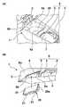
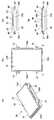
図1は、本実施形態の車両用コンソール構造の構成を説明する斜視図(a)、(b)である。図2は、本実施形態の車両用コンソール構造の車幅方向の中央部分の断面図である。図3は、本実施形態のワイヤレス充電器の外形を示す斜視図(a)、平面図(b)、後面図(c)、i−i断面図(d)である。図4は、本実施形態のワイヤレス充電器の内部構造を示す断面図である。図5は、本実施形態のワイヤレス充電器の被水防止構造を説明する図である。 1A and 1B are perspective views (a) and (b) for explaining the configuration of the vehicle console structure of the present embodiment. FIG. 2 is a cross-sectional view of a central portion of the vehicle console structure of the present embodiment in the vehicle width direction. FIG. 3 is a perspective view (a), a plan view (b), a rear view (c), and a cross-sectional view (d) showing the outer shape of the wireless charger of the present embodiment. FIG. 4 is a cross-sectional view showing the internal structure of the wireless charger of the present embodiment. FIG. 5 is a diagram illustrating a water exposure prevention structure of the wireless charger of the present embodiment.
図1に示すように、本実施形態の車両用コンソール構造は、車室内における車幅方向の中央部に設けられているコンソールユニット1を有する。コンソールユニット1は、車体前後方向における前側の前壁部2と、車幅方向の両側の左右の側壁部3、4と、を備え、左右の側壁部3、4に掛け渡された仕切り部5により分割された複数の開口6、7が形成されている。本実施形態では、例えば、仕切り部5により分割された前部開口6、後部開口7が形成されている。 As shown in FIG. 1, the vehicle console structure of the present embodiment has a console unit 1 provided at the center in the vehicle interior in the vehicle width direction. The console unit 1 includes a
前部開口6には、ワイヤレス充電器20が配置される。ワイヤレス充電器20は、左右の側面部に複数(例えば、4箇所)の取付部21を有し、これらの取付部21が前部開口6の左右の側壁部6a、6bの裏面にビスなどで固定される。これにより、ワイヤレス充電器20によりコンソールユニット1の前部開口6が閉塞される。また、ワイヤレス充電器20は車両前方から車両後方に向かって上り勾配に傾斜するような姿勢でコンソールユニット1の前部開口6に取り付けられる。ワイヤレス充電器20がコンソールユニット1に取り付けられた状態において、ワイヤレス充電器20の上面部31に被充電機器100(図2参照)が配置されると、被充電機器100に対して非接触で電力を送電可能であり、被充電機器100はワイヤレス充電器20から受け取った電力によりバッテリの充電などが可能となる。なお、被充電機器100は、例えばスマートフォンやタブレット端末などの携帯型電子機器である。
コンソール部8は、後部開口7の左右の側壁部3、4と仕切り部5から構成されており、仕切り部5がコンソール部8の前端部を構成している。コンソールユニット1には、ワイヤレス充電器20とコンソール部8の2つが車体前方から順に配置されている。ワイヤレス充電器20がコンソールユニット1に取り付けられた状態において、ワイヤレス充電器20の後端部20aとコンソールユニット部7の仕切り部5の車体前方に突出する突出部5aとは車体上方から見て重なるように配置され、ワイヤレス充電器20と仕切り部5との合わせ部分12(図2参照)には後述する被水防止構造が設けられている。後部開口7には、変速機の操作レバー(シフトレバーやセレクトレバー)やパーキングブレーキの操作レバー(サイドレバー)などが配置される。A
The
図2に示すように、本実施形態の被水防止構造は、ワイヤレス充電器20と仕切り部5の合わせ部分12の隙間部分から内部に浸入する水などの液体がワイヤレス充電器20の内部に浸入することを防止する庇形状部40を備える。庇形状部40は、仕切り部5側に延びる平面形状を有し、仕切り部5の突出部5aに対して鉛直方向における下方に位置し車体前後方向に重なるように設けられている。庇形状部40は、ワイヤレス充電器20と仕切り部5の合わせ部分12の隙間部分に浸入する液体を、ワイヤレス充電器20の車幅方向における左右の側面部33b、33d(図3参照)の少なくともいずれかの端部側に誘導し、排出する機能を有する。 As shown in FIG. 2, in the water exposure prevention structure of the present embodiment, a liquid such as water that infiltrates into the inside through the gap portion of the
ワイヤレス充電器20は、被充電機器100またはワイヤレス充電器20の発熱による温度上昇を抑制するために、不図示のファンなどにより外部からエアなどの流体を吸入し、機器内部に流通させて排出する冷却エア通路23〜25が形成されている。 The
図3および図4に示すように、ワイヤレス充電器20は、外形を構成する中空の枠体30を有する。枠体30は、上面部31、下面部32、前後左右の4つの側面部33a〜33dを有し、上面部31および下面部32の縦横の長さに対して側面部33a〜33dの高さが低い箱体状である。枠体30の内部には、メイン基板34、コイルブラケット35、磁性体36、コイル37などが配置されている。 As shown in FIGS. 3 and 4, the
また、枠体30の内部に形成された冷却エア通路23〜25は、流入口23、流路24、流出口25を含む。流入口23は枠体30の前部において下方に開口している。流路24は枠体30の上面部31の下面と枠体30の内部の部品を保持する保持部材38の上面との間に形成され、流入口23と流出口25との間を連通する隙間を形成している。流出口25は枠体30の後部において後方に開口している。冷却エア通路23〜25は、枠体30の前部の流入口23から、枠体30の上面部31の下面と保持部材38の上面の隙間を通って、後部の流出口25にエアを流通させ、ワイヤレス充電器20やその上に配置された被充電機器100またはワイヤレス充電器20の発熱による温度上昇を抑制する。 Further, the
このように冷却エア通路23〜25を設け、ワイヤレス充電器20が車両前方から車両後方に向かって上り勾配に傾斜するような姿勢でコンソールユニット1の前部開口6に取り付けられるので、温かい空気が上方に設けられた流出口25に向かうため排熱性能が向上する。 Since the cooling
また、また、ワイヤレス充電器20は、その上面部31が車体前方から車両後方に向かって上り勾配に傾斜している。これにより、車両発進時などに端末が移動することが防止される。 Further, the
また、ワイヤレス充電器20の左右の側面部33b、33dのうち少なくとも一方は、コンソールユニット1の前部開口6の左右の側壁部6a、6bと隣接し、ワイヤレス充電器20の上面部31よりも上方に立設している。このような構成により、ワイヤレス充電器20の上面部31に配置されている被充電機器100やその他の物品が左右のいずれかに落下してしまうことを防止できる。なお、コンソールユニット1の前部開口6の左右の側壁部6a、6bの高さは、ワイヤレス充電器20の上面部31よりも高い構成に限らず、例えば、左右の側壁部6a、6bのいずれかまたは両方がワイヤレス充電器20の上面部31と同等の高さまたは低い構成であってもよい。 Further, at least one of the left and right
また、ワイヤレス充電器20の上面部31が、被充電機器100やその他の物品の収納スペースとしても利用可能となる。 Further, the
また、ワイヤレス充電器20を傾斜させることによって仕切り部5との合わせ部分12に隙間ができやすくなること、並びに、流出口25が車体後方側であって、仕切り部5との合わせ部分12の近くに設けられていることで、ワイヤレス充電器20と仕切り部5との合わせ部分12の隙間部分から液体が浸入するおそれが増加するが、庇形状部40を設けたことによってワイヤレス充電器20の内部の被水が防止される。 Further, by inclining the
前後左右の側面部33a〜33dは、車体前後方向における前側の前面部33aと、後側の後面部33cと、車幅方向の両側の左右の側面部33b、33dと、を備え、左右の側面部33b、33dに取付部21が設けられる。 The front, rear, left and right
庇形状部40は、ワイヤレス充電器20における、枠体30の後面部33c(上面部31の後端部20a)から車体後方に延びるように突出して設けられている。庇形状部40は、枠体30の後面部33cにおいて車幅方向の中央部から左右の側面部33b、33dの方向に所定の範囲に設けられている。庇形状部40は、冷却エア通路23〜25における流出口25の直上方に設けられ、ワイヤレス充電器20と仕切り部5との合わせ部分12から液体が浸入しても流出口25から機器の内部に流入しないように左右の側面部33b、33dの方向に排出する。 The eaves-shaped
図5に示すように、ワイヤレス充電器20の枠体30の後面部33c(上面部31の後端部20a)における、庇形状部40の車幅方向の両側には溝部41が連続して形成されている。溝部41は、庇形状部40の左右両端40aから下方に傾斜して車幅方向両側に延び、さらに左右の側面部33b、33dまで曲折して連続して延びる延長部42を有する。このような被水防止構造を設けたことにより、ワイヤレス充電器20と仕切り部5との合わせ部分12の隙間部分に浸入した液体は庇形状部40を通って両側の溝部41に誘導されて排水されるため、ワイヤレス充電器20の内部への液体の浸入が防止される。 As shown in FIG. 5,
また、ワイヤレス充電器20と仕切り部5との合わせ部分12の隙間部分に浸入した液体を隙間部分から遠ざけるように流すことができ、ワイヤレス充電器20の被水のおそれをより低下させることができる。 Further, the liquid that has penetrated into the gap portion of the
本実施形態の被水防止構造によれば、ワイヤレス充電器20の内部の電気回路であるメイン基板34やコイル37が被水することが防止される。 According to the water exposure prevention structure of the present embodiment, the
なお、図5(d)に示すように、庇形状部40を鉛直方向において上方に突出する凸形状とし、凸形状の頂部40cからワイヤレス充電器20の左右の側面部33b、33dに向かって下り勾配に傾斜した構成としてもよい。このように構成することで、ワイヤレス充電器20と仕切り部5との合わせ部分12の隙間部分に浸入した液体を溝部41に向けてより効果的に排水することができるようになる。 As shown in FIG. 5D, the eaves-shaped
[実施形態のまとめ]
<第1の態様>
車両用コンソール構造であって、
コンソール部8と、
被充電機器100に対して非接触で電力を送電可能な非接触充電部20と、を備え、
前記コンソール部8は前記非接触充電部20よりも車体後方に位置し、
前記コンソール部8は前記非接触充電部20との仕切り部5を有し、
前記仕切り部5には車体前方に突出する突出部5aが設けられ、
前記非接触充電部20の後端部20aには前記仕切り部5側に延びる庇形状部40が設けられ、
前記突出部5aと前記非接触充電部20の庇形状部40とが車体上方から見て重なるように配置され、
前記庇形状部40が、前記突出部5aに対して鉛直方向における下方に位置するように設けられている。[Summary of Embodiment]
<First aspect>
It is a vehicle console structure
A
The
The
The
The
The protruding
The eaves-shaped
第1の態様によれば、非接触充電部20と仕切り部5との合わせ部分12の隙間部分から浸入する液体が非接触充電部20の内部に浸入することが防止される。 According to the first aspect, the liquid that infiltrates through the gap portion of the
<第2の態様>
第1の態様において、前記庇形状部40は、前記非接触充電部20の後端部20aにおいて車幅方向に延びる平面部40と、前記平面部40から車幅方向に延びる溝部41を有する。<Second aspect>
In the first aspect, the eaves-shaped
第2の態様によれば、非接触充電部20と仕切り部5との合わせ部分12の隙間部分に浸入した液体は庇形状部40を通って両側の溝部41に誘導されて排水されるため、非接触充電部20の内部への液体の浸入が防止される。 According to the second aspect, the liquid that has entered the gap portion of the
<第3の態様>
第1または第2の態様において、前記溝部41は、前記非接触充電部20の車幅方向の側面部33b、33dまで延びている。<Third aspect>
In the first or second aspect, the
第3の態様によれば、非接触充電部20と仕切り部5との合わせ部分12の隙間部分に浸入した液体を隙間部分から遠ざけるように流すことができ、非接触充電部20の被水のおそれをより低下させることができる。 According to the third aspect, the liquid that has penetrated into the gap portion of the
<第4の態様>
第1から第3のいずれかの態様において、前記庇形状部40は、鉛直方向において上方に突出する凸形状を有し、
前記凸形状の頂部40aから前記非接触充電部20の車幅方向に向かって下り勾配に傾斜している。<Fourth aspect>
In any one of the first to third aspects, the eaves-shaped
The convex top 40a is inclined downward toward the vehicle width direction of the
第4の態様によれば、非接触充電部20と仕切り部5との合わせ部分12の隙間部分に浸入した液体を側面部33b、33dに向けてより効果的に排水することができる。 According to the fourth aspect, the liquid that has penetrated into the gap portion of the
<第5の態様>
第1から第4のいずれかの態様において、前記非接触充電部20は、車体前方から車体後方に向かって上り勾配に傾斜するように配置されている。<Fifth aspect>
In any one of the first to fourth aspects, the
第5の態様によれば、車両発進時などに端末が移動することが防止される。 According to the fifth aspect, the terminal is prevented from moving when the vehicle starts.
<第6の態様>
第1から第5のいずれかの態様において、前記非接触充電部20の車幅方向の側面部33b、33dの少なくともいずれかに隣接し、前記非接触充電部20の上面部31よりも上方に立設された側壁部6a、6bを有する。<Sixth aspect>
In any one of the first to fifth aspects, the
第6の態様によれば、非接触充電部20の上面部31に配置されている被充電機器100やその他の物品が左右のいずれかに落下してしまうことを防止できる。 According to the sixth aspect, it is possible to prevent the device to be charged 100 and other articles arranged on the
また、非接触充電部20の上面部31が、被充電機器100やその他の物品の収納スペースとしても利用可能となる。 Further, the
<第7の態様>
第1から第6のいずれかの態様において、前記非接触充電部20は、
エアの流入口23と、
エアの流出口25と、
前記流入口23から前記流出口25にエアが流れる流路24と、を有し、
前記流出口25が前記非接触充電部20における車体後方側に設けられている。<7th aspect>
In any one of the first to sixth aspects, the
It has a
The
第7の態様によれば、非接触充電部20が車体前方から車体後方に向かって上り勾配に傾斜するように配置されている場合、温かい空気が上方に設けられた流出口25に向かうため排熱性能が向上する。また、流出口25が車体後方側に設けられていることで非接触充電部20と仕切り部5との合わせ部分12の隙間部分から液体が浸入するおそれが増加するが、庇形状部40を設けたことによって非接触充電部20の内部の被水が防止される。 According to the seventh aspect, when the
<第8の態様>
車両用コンソール構造であって、
コンソール部8と、
被充電機器100に対して非接触で電力を送電可能な非接触充電部20と、を備え、
前記非接触充電部20は、
エアの流入口23と、エアの流出口25と、前記流入口23から前記流出口25にエアが流通可能な流路24と、を有し、
前記流出口25が前記非接触充電部20における車体後方側に設けられ、
車体前方から車体後方に向かって上り勾配に傾斜するように配置され、
前記流出口25が前記流入口23よりも鉛直方向の上方に位置する。<8th aspect>
It is a vehicle console structure
A
The
It has an
The
Arranged so as to incline uphill from the front of the car body to the rear of the car body
The
第8の態様によれば、非接触充電部20が車両前方から車両後方に向かって上り勾配に傾斜するような姿勢で配置されるので、温かい空気が上方に設けられた流出口25に向かうため排熱性能が向上する。 According to the eighth aspect, since the
1…コンソールユニット
2…前壁部
3、4…側壁部
5…仕切り部
5a…突出部
6…前部開口
6a、6b…前部開口6の側壁部
7…後部開口
8…コンソール部
12…ワイヤレス充電器20と仕切り部5との合わせ部分
20…ワイヤレス充電器(非接触充電部)
20a…後端部
21…取付部
23〜25…冷却エア通路
23…流入口
24…流路
25…流出口
30…枠体
31…上面部
32…下面部
33a…前面部
33b、33d…側面部
33c…後面部
34…メイン基板
35…コイルブラケット
36…磁性体
37…コイル
38…保持部材
40…庇形状部
40a、40b…庇形状部40の左右両端
40c…凸形状の頂部
41…溝部
42…延長部
100…被充電機器1 ...
20a ...
Claims (6)
Translated fromJapaneseコンソール部と、
被充電機器に対して非接触で電力を送電可能な非接触充電部と、を備え、
前記コンソール部は前記非接触充電部よりも車体後方に位置し、
前記コンソール部は前記非接触充電部との仕切り部を有し、
前記仕切り部には車体前方に突出する突出部が設けられ、
前記非接触充電部の後端部には前記仕切り部側に延びる庇形状部が設けられ、
前記突出部と前記非接触充電部の庇形状部とが車体上方から見て重なるように配置され、
前記庇形状部は、前記突出部に対して鉛直方向における下方に位置するように設けられ、
前記非接触充電部の後端部において車幅方向に延びる平面部と、前記平面部から車幅方向に延びる溝部と、を有することを特徴とする車両用コンソール構造。It is a vehicle console structure
Console part and
It is equipped with a non-contact charging unit that can transmit power to the device to be charged in a non-contact manner.
The console unit is located behind the vehicle body with respect to the non-contact charging unit.
The console portion has a partition portion from the non-contact charging portion, and has a partition portion.
The partition is provided with a protrusion that protrudes forward of the vehicle body.
An eaves-shaped portion extending toward the partition portion is provided at the rear end portion of the non-contact charging portion.
The protruding portion and the eaves-shaped portion of the non-contact charging portion are arranged so as to overlap each other when viewed from above the vehicle body.
The eaves-shaped portionis provided so as to be located below the protruding portion in the vertical direction.
The non-contact with the flat portion extending in the vehicle width direction at the rear end of the charging unit, a vehicle console structure, characterized in Rukototo have a, a groove extending in the vehicle width direction from the planar portion.
前記凸形状の頂部から前記非接触充電部の車幅方向に向かって下り勾配に傾斜していることを特徴とする請求項1または2に記載の車両用コンソール構造。The eaves-shaped portion has a convex shape protruding upward in the vertical direction.
The vehicle console structure accordingto claim 1 or 2 , wherein the non-contact charging portion is inclined downward from the top of the convex shape toward the vehicle width direction.
エアの流入口と、
エアの流出口と、
前記流入口から前記流出口にエアが流れる流路と、を有し、
前記流出口が前記非接触充電部における車体後方側に設けられていることを特徴とする請求項1から5のいずれか1項に記載の車両用コンソール構造。The non-contact charging unit
Air inlet and
Air outlet and
It has a flow path through which air flows from the inlet to the outlet.
The vehicle console structure according to anyone of claims 1 to 5 , wherein the outlet is provided on the rear side of the vehicle body in the non-contact charging unit.
Priority Applications (1)
| Application Number | Priority Date | Filing Date | Title |
|---|---|---|---|
| JP2019190437AJP6963595B2 (en) | 2019-10-17 | 2019-10-17 | Vehicle console structure |
Applications Claiming Priority (1)
| Application Number | Priority Date | Filing Date | Title |
|---|---|---|---|
| JP2019190437AJP6963595B2 (en) | 2019-10-17 | 2019-10-17 | Vehicle console structure |
Publications (2)
| Publication Number | Publication Date |
|---|---|
| JP2021066200A JP2021066200A (en) | 2021-04-30 |
| JP6963595B2true JP6963595B2 (en) | 2021-11-10 |
Family
ID=75636483
Family Applications (1)
| Application Number | Title | Priority Date | Filing Date |
|---|---|---|---|
| JP2019190437AActiveJP6963595B2 (en) | 2019-10-17 | 2019-10-17 | Vehicle console structure |
Country Status (1)
| Country | Link |
|---|---|
| JP (1) | JP6963595B2 (en) |
Families Citing this family (1)
| Publication number | Priority date | Publication date | Assignee | Title |
|---|---|---|---|---|
| KR102737375B1 (en)* | 2022-11-04 | 2024-12-03 | 주식회사 서연이화 | Mobile phone charging device deployed in vehicle and vehicle equipped therewith |
Family Cites Families (11)
| Publication number | Priority date | Publication date | Assignee | Title |
|---|---|---|---|---|
| US7612528B2 (en)* | 1999-06-21 | 2009-11-03 | Access Business Group International Llc | Vehicle interface |
| US8310200B2 (en)* | 2009-04-15 | 2012-11-13 | GM Global Technology Operations LLC | Inductive chargers and inductive charging systems for portable electronic devices |
| JP5264974B2 (en)* | 2011-02-01 | 2013-08-14 | 本田技研工業株式会社 | Non-contact power transmission device |
| EP2701269A4 (en)* | 2011-04-22 | 2015-08-12 | Panasonic Ip Man Co Ltd | Vehicle-mounting charging apparatus and vehicle mounted therewith |
| US9018904B2 (en)* | 2011-08-12 | 2015-04-28 | GM Global Technology Operations LLC | Wireless battery charging apparatus mounted in a vehicle designed to reduce electromagnetic interference |
| JP2013106428A (en)* | 2011-11-14 | 2013-05-30 | Panasonic Corp | Charging base for contactless charging |
| US9124109B2 (en)* | 2012-03-30 | 2015-09-01 | Toyota Motor Engineering & Manufacturing North America, Inc. | Console assembly with charging state indicator |
| US8783752B2 (en)* | 2012-12-18 | 2014-07-22 | Toyota Motor Engineering & Manufacturing North America, Inc. | Mobile device retention and charging tray |
| TWM466415U (en)* | 2013-06-05 | 2013-11-21 | yu-xiong Fan | Fixing device with wireless charging function |
| JP6226718B2 (en)* | 2013-11-26 | 2017-11-08 | 矢崎総業株式会社 | Wireless power supply system |
| JP6882660B2 (en)* | 2016-11-07 | 2021-06-02 | テイ・エス テック株式会社 | Vehicle seat |
- 2019
- 2019-10-17JPJP2019190437Apatent/JP6963595B2/enactiveActive
Also Published As
| Publication number | Publication date |
|---|---|
| JP2021066200A (en) | 2021-04-30 |
Similar Documents
| Publication | Publication Date | Title |
|---|---|---|
| JP6622368B2 (en) | Automotive battery | |
| CN100487951C (en) | Battery module | |
| CN101685872B (en) | On-board battery assembly | |
| KR101989464B1 (en) | Wireless power transfer apparatus for vehicle | |
| JP2011006051A (en) | Vehicle battery assembly cooling structure, and battery assembly with water jacket | |
| CN104347910A (en) | Battery cooling system | |
| CN107710867B (en) | fluid heating device | |
| JP2009016076A (en) | Cover member and power supply device including the cover member | |
| JP6963595B2 (en) | Vehicle console structure | |
| JP2017050237A (en) | Cooling structure for battery pack for vehicle | |
| JP2009289636A (en) | Temperature adjusting structure of power supply apparatus | |
| JP2023029417A (en) | Cooling device and vehicle | |
| KR102773137B1 (en) | On board charger housing for electric vehicle or hybrid vehicle | |
| JP6851431B2 (en) | Vehicle cooling structure | |
| JP6285197B2 (en) | Automotive battery | |
| US8974941B2 (en) | Storage device for battery modules | |
| JPWO2013084940A1 (en) | Battery pack for electric vehicles | |
| JP2019106319A (en) | Battery pack | |
| JP2016170863A (en) | Heating element cooling structure | |
| JP7314705B2 (en) | vehicle battery pack | |
| KR102773153B1 (en) | On board charger with cooling system for electric vehicle | |
| JP2021118090A (en) | Vehicle battery pack | |
| KR20240086171A (en) | High voltage battery module | |
| JP7622677B2 (en) | Oil cooler | |
| JP2021027012A (en) | Air circulation apparatus |
Legal Events
| Date | Code | Title | Description |
|---|---|---|---|
| A621 | Written request for application examination | Free format text:JAPANESE INTERMEDIATE CODE: A621 Effective date:20200529 | |
| RD02 | Notification of acceptance of power of attorney | Free format text:JAPANESE INTERMEDIATE CODE: A7422 Effective date:20210103 | |
| A521 | Written amendment | Free format text:JAPANESE INTERMEDIATE CODE: A523 Effective date:20210125 | |
| A131 | Notification of reasons for refusal | Free format text:JAPANESE INTERMEDIATE CODE: A131 Effective date:20210712 | |
| A521 | Written amendment | Free format text:JAPANESE INTERMEDIATE CODE: A523 Effective date:20210906 | |
| TRDD | Decision of grant or rejection written | ||
| A01 | Written decision to grant a patent or to grant a registration (utility model) | Free format text:JAPANESE INTERMEDIATE CODE: A01 Effective date:20211008 | |
| A61 | First payment of annual fees (during grant procedure) | Free format text:JAPANESE INTERMEDIATE CODE: A61 Effective date:20211015 | |
| R150 | Certificate of patent or registration of utility model | Ref document number:6963595 Country of ref document:JP Free format text:JAPANESE INTERMEDIATE CODE: R150 |