JP6961803B2 - Automatic parking for virtual parking spots - Google Patents
Automatic parking for virtual parking spotsDownload PDFInfo
- Publication number
- JP6961803B2 JP6961803B2JP2020512523AJP2020512523AJP6961803B2JP 6961803 B2JP6961803 B2JP 6961803B2JP 2020512523 AJP2020512523 AJP 2020512523AJP 2020512523 AJP2020512523 AJP 2020512523AJP 6961803 B2JP6961803 B2JP 6961803B2
- Authority
- JP
- Japan
- Prior art keywords
- vehicle
- parking
- electronic controller
- reference point
- parking position
- Prior art date
- Legal status (The legal status is an assumption and is not a legal conclusion. Google has not performed a legal analysis and makes no representation as to the accuracy of the status listed.)
- Expired - Fee Related
Links
Images


Classifications
- B—PERFORMING OPERATIONS; TRANSPORTING
- B60—VEHICLES IN GENERAL
- B60R—VEHICLES, VEHICLE FITTINGS, OR VEHICLE PARTS, NOT OTHERWISE PROVIDED FOR
- B60R1/00—Optical viewing arrangements; Real-time viewing arrangements for drivers or passengers using optical image capturing systems, e.g. cameras or video systems specially adapted for use in or on vehicles
- B60R1/20—Real-time viewing arrangements for drivers or passengers using optical image capturing systems, e.g. cameras or video systems specially adapted for use in or on vehicles
- B60R1/22—Real-time viewing arrangements for drivers or passengers using optical image capturing systems, e.g. cameras or video systems specially adapted for use in or on vehicles for viewing an area outside the vehicle, e.g. the exterior of the vehicle
- B60R1/23—Real-time viewing arrangements for drivers or passengers using optical image capturing systems, e.g. cameras or video systems specially adapted for use in or on vehicles for viewing an area outside the vehicle, e.g. the exterior of the vehicle with a predetermined field of view
- B60R1/26—Real-time viewing arrangements for drivers or passengers using optical image capturing systems, e.g. cameras or video systems specially adapted for use in or on vehicles for viewing an area outside the vehicle, e.g. the exterior of the vehicle with a predetermined field of view to the rear of the vehicle
- B—PERFORMING OPERATIONS; TRANSPORTING
- B60—VEHICLES IN GENERAL
- B60R—VEHICLES, VEHICLE FITTINGS, OR VEHICLE PARTS, NOT OTHERWISE PROVIDED FOR
- B60R1/00—Optical viewing arrangements; Real-time viewing arrangements for drivers or passengers using optical image capturing systems, e.g. cameras or video systems specially adapted for use in or on vehicles
- B60R1/002—Optical viewing arrangements; Real-time viewing arrangements for drivers or passengers using optical image capturing systems, e.g. cameras or video systems specially adapted for use in or on vehicles specially adapted for covering the peripheral part of the vehicle, e.g. for viewing tyres, bumpers or the like
- B60R1/003—Optical viewing arrangements; Real-time viewing arrangements for drivers or passengers using optical image capturing systems, e.g. cameras or video systems specially adapted for use in or on vehicles specially adapted for covering the peripheral part of the vehicle, e.g. for viewing tyres, bumpers or the like for viewing trailer hitches
- B—PERFORMING OPERATIONS; TRANSPORTING
- B60—VEHICLES IN GENERAL
- B60T—VEHICLE BRAKE CONTROL SYSTEMS OR PARTS THEREOF; BRAKE CONTROL SYSTEMS OR PARTS THEREOF, IN GENERAL; ARRANGEMENT OF BRAKING ELEMENTS ON VEHICLES IN GENERAL; PORTABLE DEVICES FOR PREVENTING UNWANTED MOVEMENT OF VEHICLES; VEHICLE MODIFICATIONS TO FACILITATE COOLING OF BRAKES
- B60T7/00—Brake-action initiating means
- B60T7/12—Brake-action initiating means for automatic initiation; for initiation not subject to will of driver or passenger
- B60T7/22—Brake-action initiating means for automatic initiation; for initiation not subject to will of driver or passenger initiated by contact of vehicle, e.g. bumper, with an external object, e.g. another vehicle, or by means of contactless obstacle detectors mounted on the vehicle
- B—PERFORMING OPERATIONS; TRANSPORTING
- B60—VEHICLES IN GENERAL
- B60T—VEHICLE BRAKE CONTROL SYSTEMS OR PARTS THEREOF; BRAKE CONTROL SYSTEMS OR PARTS THEREOF, IN GENERAL; ARRANGEMENT OF BRAKING ELEMENTS ON VEHICLES IN GENERAL; PORTABLE DEVICES FOR PREVENTING UNWANTED MOVEMENT OF VEHICLES; VEHICLE MODIFICATIONS TO FACILITATE COOLING OF BRAKES
- B60T8/00—Arrangements for adjusting wheel-braking force to meet varying vehicular or ground-surface conditions, e.g. limiting or varying distribution of braking force
- B60T8/17—Using electrical or electronic regulation means to control braking
- B—PERFORMING OPERATIONS; TRANSPORTING
- B60—VEHICLES IN GENERAL
- B60W—CONJOINT CONTROL OF VEHICLE SUB-UNITS OF DIFFERENT TYPE OR DIFFERENT FUNCTION; CONTROL SYSTEMS SPECIALLY ADAPTED FOR HYBRID VEHICLES; ROAD VEHICLE DRIVE CONTROL SYSTEMS FOR PURPOSES NOT RELATED TO THE CONTROL OF A PARTICULAR SUB-UNIT
- B60W30/00—Purposes of road vehicle drive control systems not related to the control of a particular sub-unit, e.g. of systems using conjoint control of vehicle sub-units
- B60W30/06—Automatic manoeuvring for parking
- B—PERFORMING OPERATIONS; TRANSPORTING
- B62—LAND VEHICLES FOR TRAVELLING OTHERWISE THAN ON RAILS
- B62D—MOTOR VEHICLES; TRAILERS
- B62D13/00—Steering specially adapted for trailers
- B62D13/06—Steering specially adapted for trailers for backing a normally drawn trailer
- B—PERFORMING OPERATIONS; TRANSPORTING
- B62—LAND VEHICLES FOR TRAVELLING OTHERWISE THAN ON RAILS
- B62D—MOTOR VEHICLES; TRAILERS
- B62D15/00—Steering not otherwise provided for
- B62D15/02—Steering position indicators ; Steering position determination; Steering aids
- B62D15/027—Parking aids, e.g. instruction means
- B62D15/0285—Parking performed automatically
- G—PHYSICS
- G05—CONTROLLING; REGULATING
- G05D—SYSTEMS FOR CONTROLLING OR REGULATING NON-ELECTRIC VARIABLES
- G05D1/00—Control of position, course, altitude or attitude of land, water, air or space vehicles, e.g. using automatic pilots
- G05D1/02—Control of position or course in two dimensions
- G05D1/021—Control of position or course in two dimensions specially adapted to land vehicles
- G05D1/0212—Control of position or course in two dimensions specially adapted to land vehicles with means for defining a desired trajectory
- G—PHYSICS
- G05—CONTROLLING; REGULATING
- G05D—SYSTEMS FOR CONTROLLING OR REGULATING NON-ELECTRIC VARIABLES
- G05D1/00—Control of position, course, altitude or attitude of land, water, air or space vehicles, e.g. using automatic pilots
- G05D1/02—Control of position or course in two dimensions
- G05D1/021—Control of position or course in two dimensions specially adapted to land vehicles
- G05D1/0231—Control of position or course in two dimensions specially adapted to land vehicles using optical position detecting means
- G05D1/0246—Control of position or course in two dimensions specially adapted to land vehicles using optical position detecting means using a video camera in combination with image processing means
- G—PHYSICS
- G05—CONTROLLING; REGULATING
- G05D—SYSTEMS FOR CONTROLLING OR REGULATING NON-ELECTRIC VARIABLES
- G05D1/00—Control of position, course, altitude or attitude of land, water, air or space vehicles, e.g. using automatic pilots
- G05D1/20—Control system inputs
- G05D1/24—Arrangements for determining position or orientation
- G05D1/246—Arrangements for determining position or orientation using environment maps, e.g. simultaneous localisation and mapping [SLAM]
- G—PHYSICS
- G08—SIGNALLING
- G08G—TRAFFIC CONTROL SYSTEMS
- G08G1/00—Traffic control systems for road vehicles
- G08G1/14—Traffic control systems for road vehicles indicating individual free spaces in parking areas
- G08G1/141—Traffic control systems for road vehicles indicating individual free spaces in parking areas with means giving the indication of available parking spaces
- G08G1/143—Traffic control systems for road vehicles indicating individual free spaces in parking areas with means giving the indication of available parking spaces inside the vehicles
- G—PHYSICS
- G08—SIGNALLING
- G08G—TRAFFIC CONTROL SYSTEMS
- G08G1/00—Traffic control systems for road vehicles
- G08G1/16—Anti-collision systems
- G08G1/168—Driving aids for parking, e.g. acoustic or visual feedback on parking space
- B—PERFORMING OPERATIONS; TRANSPORTING
- B60—VEHICLES IN GENERAL
- B60R—VEHICLES, VEHICLE FITTINGS, OR VEHICLE PARTS, NOT OTHERWISE PROVIDED FOR
- B60R2300/00—Details of viewing arrangements using cameras and displays, specially adapted for use in a vehicle
- B60R2300/80—Details of viewing arrangements using cameras and displays, specially adapted for use in a vehicle characterised by the intended use of the viewing arrangement
- B60R2300/806—Details of viewing arrangements using cameras and displays, specially adapted for use in a vehicle characterised by the intended use of the viewing arrangement for aiding parking
- B—PERFORMING OPERATIONS; TRANSPORTING
- B60—VEHICLES IN GENERAL
- B60T—VEHICLE BRAKE CONTROL SYSTEMS OR PARTS THEREOF; BRAKE CONTROL SYSTEMS OR PARTS THEREOF, IN GENERAL; ARRANGEMENT OF BRAKING ELEMENTS ON VEHICLES IN GENERAL; PORTABLE DEVICES FOR PREVENTING UNWANTED MOVEMENT OF VEHICLES; VEHICLE MODIFICATIONS TO FACILITATE COOLING OF BRAKES
- B60T2201/00—Particular use of vehicle brake systems; Special systems using also the brakes; Special software modules within the brake system controller
- B60T2201/10—Automatic or semi-automatic parking aid systems
- B—PERFORMING OPERATIONS; TRANSPORTING
- B60—VEHICLES IN GENERAL
- B60W—CONJOINT CONTROL OF VEHICLE SUB-UNITS OF DIFFERENT TYPE OR DIFFERENT FUNCTION; CONTROL SYSTEMS SPECIALLY ADAPTED FOR HYBRID VEHICLES; ROAD VEHICLE DRIVE CONTROL SYSTEMS FOR PURPOSES NOT RELATED TO THE CONTROL OF A PARTICULAR SUB-UNIT
- B60W2420/00—Indexing codes relating to the type of sensors based on the principle of their operation
- B60W2420/40—Photo, light or radio wave sensitive means, e.g. infrared sensors
- B60W2420/403—Image sensing, e.g. optical camera
- B—PERFORMING OPERATIONS; TRANSPORTING
- B60—VEHICLES IN GENERAL
- B60W—CONJOINT CONTROL OF VEHICLE SUB-UNITS OF DIFFERENT TYPE OR DIFFERENT FUNCTION; CONTROL SYSTEMS SPECIALLY ADAPTED FOR HYBRID VEHICLES; ROAD VEHICLE DRIVE CONTROL SYSTEMS FOR PURPOSES NOT RELATED TO THE CONTROL OF A PARTICULAR SUB-UNIT
- B60W2420/00—Indexing codes relating to the type of sensors based on the principle of their operation
- B60W2420/40—Photo, light or radio wave sensitive means, e.g. infrared sensors
- B60W2420/408—Radar; Laser, e.g. lidar
- B—PERFORMING OPERATIONS; TRANSPORTING
- B60—VEHICLES IN GENERAL
- B60W—CONJOINT CONTROL OF VEHICLE SUB-UNITS OF DIFFERENT TYPE OR DIFFERENT FUNCTION; CONTROL SYSTEMS SPECIALLY ADAPTED FOR HYBRID VEHICLES; ROAD VEHICLE DRIVE CONTROL SYSTEMS FOR PURPOSES NOT RELATED TO THE CONTROL OF A PARTICULAR SUB-UNIT
- B60W2420/00—Indexing codes relating to the type of sensors based on the principle of their operation
- B60W2420/54—Audio sensitive means, e.g. ultrasound
- B—PERFORMING OPERATIONS; TRANSPORTING
- B60—VEHICLES IN GENERAL
- B60W—CONJOINT CONTROL OF VEHICLE SUB-UNITS OF DIFFERENT TYPE OR DIFFERENT FUNCTION; CONTROL SYSTEMS SPECIALLY ADAPTED FOR HYBRID VEHICLES; ROAD VEHICLE DRIVE CONTROL SYSTEMS FOR PURPOSES NOT RELATED TO THE CONTROL OF A PARTICULAR SUB-UNIT
- B60W2554/00—Input parameters relating to objects
- B60W2554/80—Spatial relation or speed relative to objects
- G—PHYSICS
- G05—CONTROLLING; REGULATING
- G05D—SYSTEMS FOR CONTROLLING OR REGULATING NON-ELECTRIC VARIABLES
- G05D1/00—Control of position, course, altitude or attitude of land, water, air or space vehicles, e.g. using automatic pilots
- G05D1/02—Control of position or course in two dimensions
- G05D1/021—Control of position or course in two dimensions specially adapted to land vehicles
- G05D1/0257—Control of position or course in two dimensions specially adapted to land vehicles using a radar
Landscapes
- Engineering & Computer Science (AREA)
- Mechanical Engineering (AREA)
- Transportation (AREA)
- Physics & Mathematics (AREA)
- General Physics & Mathematics (AREA)
- Automation & Control Theory (AREA)
- Multimedia (AREA)
- Chemical & Material Sciences (AREA)
- Combustion & Propulsion (AREA)
- Remote Sensing (AREA)
- Radar, Positioning & Navigation (AREA)
- Aviation & Aerospace Engineering (AREA)
- Computer Vision & Pattern Recognition (AREA)
- Electromagnetism (AREA)
- Traffic Control Systems (AREA)
- Control Of Driving Devices And Active Controlling Of Vehicle (AREA)
Description
Translated fromJapanese 技術分野
実施形態は、車両の自動駐車に関する。Technical field Embodiments relate to automatic parking of vehicles.
背景
最新の車両には、例えば、アダプティブクルーズコントロール、衝突回避システム、セルフパーキング等、種々の部分的な自動運転機能が含まれている。目標は完全自動運転であるが、これは、少なくとも市場対応可能な、商業的に採算がとれる規模ではまだ達成されていない。Background Modern vehicles include various partially autonomous driving features, such as adaptive cruise control, collision avoidance systems, and self-parking. The goal is fully autonomous driving, which has not yet been achieved, at least on a marketable, commercially profitable scale.
要約
車両の自動制御の1つの態様は、自動駐車である。一部の最新の車両は、駐車線又は他の車両によって画定されている位置に自動的に駐車することができる。しかし、車両が、駐車線又は他の車両によって画定されていない領域に駐車可能である必要がある。駐車位置を画定する駐車線又は他の車両のない領域の例には、キャンプ場、ボート入水場及び芝地があり得る。これらのタイプの領域には、車両が駐車可能な位置が複数あるため、車両の自動駐車方法においては、ユーザが、自身が車両の駐車を望む位置を指定する必要がある。本明細書に記載されている実施形態は、特に、駐車線又は他の車両によって画定されていない位置に車両を自動的に駐車するためのシステム及び方法を提供する。環境検出によって、このシステムは、入力として汎用位置を受け取ると、車両を駐車する特定の位置を決定することもできる。本明細書に記載されている実施形態は、車両、トレーラ、又は、トレーラが取り付けられている車両の駐車に適用可能である。Summary One aspect of automatic control of a vehicle is automatic parking. Some modern vehicles can be automatically parked in positions defined by parking lines or other vehicles. However, the vehicle must be able to park in an area not defined by a parking line or other vehicle. Examples of areas without parking lines or other vehicles that define parking locations can be campgrounds, boat entry areas and turf. Since there are a plurality of positions in these types of areas where the vehicle can be parked, in the automatic parking method of the vehicle, the user needs to specify the position where he / she desires to park the vehicle. The embodiments described herein provide, in particular, a system and method for automatically parking a vehicle in a position not defined by a parking line or other vehicle. With environmental detection, the system can also determine a specific position to park the vehicle when it receives a generic position as input. The embodiments described herein are applicable to parking a vehicle, trailer, or vehicle to which a trailer is attached.
実施形態は、特に、駐車線又は周囲の車両によって画定されていない位置に車両を駐車するためのシステム及び方法を提供する。ある実施形態は、駐車線又は周囲の車両によって画定されていない位置に車両を駐車するためのシステムを提供する。このシステムは、ユーザインタフェースと、電磁放射線センサと、電子コントローラとを備えている。電子コントローラは、電磁放射線センサを介して、車両の周囲に関する情報を受け取る。電子コントローラは、ユーザインタフェースを介して、所望の駐車位置も受け取る。電子コントローラは、車両の周囲に関する情報と所望の駐車位置とを使用して、仮想駐車境界を作成し、基準点を決定する。電子コントローラが車両を駐車位置へ移動させるとき、電子コントローラは基準点を追跡し、車両と駐車位置との間の距離を特定し、駐車位置における又は駐車位置への車両の経路における障害物を検出する。 The embodiment provides, in particular, a system and method for parking a vehicle in a position not defined by a parking line or surrounding vehicles. One embodiment provides a system for parking a vehicle in a position not defined by a parking line or surrounding vehicles. The system includes a user interface, an electromagnetic radiation sensor, and an electronic controller. The electronic controller receives information about the surroundings of the vehicle via an electromagnetic radiation sensor. The electronic controller also receives the desired parking position via the user interface. The electronic controller uses information about the surroundings of the vehicle and the desired parking position to create a virtual parking boundary and determine a reference point. When the electronic controller moves the vehicle to the parking position, the electronic controller tracks the reference point, identifies the distance between the vehicle and the parking position, and detects obstacles in the parking position or in the vehicle's path to the parking position. do.
他の実施形態は、駐車線又は周囲の車両によって画定されていない位置に車両を駐車するための方法を提供する。この方法は、電磁放射線センサを介して車両の周囲に関する情報を受け取ることと、ユーザインタフェースを介して所望の駐車位置を受け取ることとを含む。この方法はさらに、電子コントローラによって仮想駐車境界を作成することと、車両の周囲内の基準点を決定することとを含む。この方法は、車両を駐車位置へ移動させるために、車両を制御することも含む。この方法は、駐車位置と車両との間の距離を特定することと、基準点を追跡することと、車両が駐車位置へ移動するときに駐車位置における又は駐車位置への車両の経路における障害物を検出することと、を含む。 Other embodiments provide a method for parking a vehicle in a position not defined by a parking line or surrounding vehicle. The method includes receiving information about the surroundings of the vehicle via an electromagnetic radiation sensor and receiving a desired parking position via a user interface. The method further includes creating a virtual parking boundary with an electronic controller and determining a reference point within the perimeter of the vehicle. The method also includes controlling the vehicle in order to move it to a parking position. This method identifies the distance between the parking position and the vehicle, tracks the reference point, and is an obstacle in the parking position or in the vehicle's path to the parking position when the vehicle moves to the parking position. Detecting and including.
他の態様、特徴及び実施形態は、詳細な説明及び添付の図面を考慮することによって明らかになるであろう。 Other aspects, features and embodiments will be apparent by considering the detailed description and accompanying drawings.
詳細な説明
実施形態を詳細に説明する前に、本開示は、その適用において、以下の説明に記載される又は以下の図面に示される構成の詳細及びコンポーネントの配置に限定することを目的とするものではない、ということを理解されたい。実施形態は、他の構成が可能であり、種々の方法により実施又は実行可能である。Detailed Description Prior to elaborating the embodiments, the present disclosure is intended to limit its application to configuration details and component arrangements described in the following description or shown in the following drawings. Please understand that it is not a thing. The embodiments may have other configurations and may be implemented or implemented in various ways.
複数のハードウェア及びソフトウェアに基づくデバイス、並びに、複数の異なる構造コンポーネントを使用して、種々の実施形態を実装することができる。さらに、実施形態は、ハードウェア、ソフトウェア、及び、電子コンポーネント又はモジュールを含むことができ、それらは、説明の目的において、コンポーネントの大部分がハードウェアのみで実装されているかのように図示及び説明されていることがある。しかし、当業者は、この詳細な説明を読むことに基づいて、少なくとも1つの実施形態において、本発明の電子に基づく態様を、1つ以上のプロセッサにより実行可能な(例えば、不揮発性のコンピュータ可読媒体に格納されている)ソフトウェアによって実装することができることを認識するであろう。例えば、本明細書で説明される「制御ユニット」及び「コントローラ」には、1つ以上の電子プロセッサ、不揮発性のコンピュータ可読媒体を含む1つ以上のメモリモジュール、1つ以上の入出力インタフェース、1つ以上の特定用途向け集積回路(ASIC)、及び、種々のコンポーネントを接続する種々の接続(例えば、システムバス)が含まれ得る。 Various hardware and software based devices, as well as a number of different structural components, can be used to implement different embodiments. Further, embodiments can include hardware, software, and electronic components or modules, which are illustrated and described as if most of the components were implemented in hardware only for purposes of description. May have been done. However, one of ordinary skill in the art will be able to perform, in at least one embodiment, the electron-based aspects of the invention by one or more processors (eg, non-volatile computer readable) based on reading this detailed description. You will recognize that it can be implemented by software (stored on a medium). For example, the "control unit" and "controller" described herein include one or more electronic processors, one or more memory modules including non-volatile computer readable media, and one or more input / output interfaces. It may include one or more application-specific integrated circuits (ASICs) and various connections (eg, system buses) that connect different components.
図1は、駐車線又は他の車両によって画定されていない位置に車両を自動的に駐車するためのシステム105を備えた車両100を示している。車両100は、四輪車両として示されているが、種々のタイプ及び設計の車両を包含してよい。例えば、車両100は、自動車、オートバイ、トラック、バス、セミトラクタ等であってよい。車両100は、少なくともいくつかの自動機能を含むが、運転機能を実行するために運転者又は操作者を必要とする場合もある。図示の例においては、システム105は、電子コントローラ110と、ユーザインタフェース115と、環境検出システム120と、ステアリング制御システム125と、ブレーキ制御システム130と、加速制御システム135とを含むいくつかのハードウェアコンポーネントを含む。システム105のコンポーネントは、種々の構造のものであってよく、種々の通信タイプ及びプロトコルを使用してよい。 FIG. 1 shows a
電子コントローラ110は、種々の有線接続又は無線接続を介して、ユーザインタフェース115、環境検出システム120、ステアリング制御システム125、ブレーキ制御システム130及び加速制御システム135に通信可能に接続されていてよい。例えば、いくつかの実施形態においては、電子コントローラ110は、専用の線を介して、駐車線又は他の車両によって画定されていない位置に車両を自動的に駐車するためのシステム105の上記のコンポーネントの各々に直接的に結合されている。他の実施形態においては、電子コントローラ110は、車両通信バス(例えば、コントローラ領域ネットワーク(CAN)バス)又は無線接続等の共有通信リンクを介して、1つ以上のコンポーネントに通信可能に結合されている。 The
システム105の各コンポーネントは、種々の通信プロトコルを使用して、電子コントローラ110と通信することができる。図1に示されている実施形態は、システム105のコンポーネント及び接続の一例を提供しているが、これらのコンポーネント及び接続は、本明細書において図示及び説明されるもの以外の方法により構成されていてもよい。 Each component of the
図2は、トレーラ205に取り付けられている、駐車線又は他の車両によって画定されていない位置にトレーラを自動的に駐車するためのシステム210を備えた車両200の例を示している。システム210を備えた車両200は、車両100のコンポーネントと同一又は類似のコンポーネントを有している。車両200の電子コントローラ110が、トレーラ205の環境検出システム215にも接続されているため、車両200のシステム210はシステム105とは異なっている。電子コントローラ110は、車両の環境検出システム120及びトレーラの環境検出システム215から車両の周囲に関する情報及びトレーラの周囲に関する情報を受け取る。 FIG. 2 shows an example of a vehicle 200 equipped with a
電子コントローラ110は、種々の有線接続又は無線接続を介して、トレーラの環境検出システム215に通信可能に接続されているものとするとよい。例えば、いくつかの実施形態においては、電子コントローラ110は、専用の線を介してトレーラの環境検出システム215に直接的に結合されている。他の実施形態においては、電子コントローラ110は、車両通信バス(例えば、コントローラ領域ネットワーク(CAN)バス)又は無線接続等の共有通信リンクを介して、トレーラの環境検出システム215に通信可能に結合されている。 The
図3は、図1及び図2のシステムの電子コントローラ110のブロック図である。電子コントローラ110は、電力、動作制御及び保護を電子コントローラ110内のコンポーネント及びモジュールに提供する複数の電気的なコンポーネント及び電子的なコンポーネントを含む。電子コントローラ110は、特に、電子プロセッサ305(プログラミング可能な電子マイクロプロセッサ、マイクロコントローラ又は同等のデバイス等)と、メモリ310(例えば、不揮発性の機械可読メモリ)と、入出力インタフェース315と、を含む。電子プロセッサ305は、メモリ310及び入出力インタフェース315に通信可能に接続されている。電子プロセッサ305は、メモリ310及び入出力インタフェース315と連携して、特に、本明細書に記載されている方法を実施するように構成されている。 FIG. 3 is a block diagram of the
電子コントローラ110は、それぞれが、特定の機能又はサブ機能を実行するように構成されている、いくつかの独立したコントローラ(例えば、プログラミング可能な電子コントローラ)として実装されているものとしてよい。付加的に、電子コントローラ110は、追加の電子プロセッサ、メモリ、又は、入出力機能、信号処理及び以下に提示される方法のアプリケーションを処理するための特定用途向け集積回路(ASIC)を含むサブモジュールを含むものとしてよい。他の実施形態においては、電子コントローラ110は、付加的な、少数の又は異なるコンポーネントを含む。 The
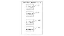
図4は、車両100の環境検出システム120及びトレーラ205の環境検出システム215のブロック図である。環境検出システム120及び215は、電磁放射線センサを含む。ライダセンサ400、ビデオカメラ405及びレーダセンサ410は、電磁放射線センサの例である。環境検出システム120及び215は、電磁放射線センサに加えて超音波センサ415も含むものとしてよい。ある実施形態においては、車両の環境は、ビデオカメラ405のみを使用して検出されるものとしてよい。他の実施形態においては、環境検出システム120及び215は、ライダセンサ400、レーダセンサ410又は超音波センサ415等の付加的なセンサを、ビデオカメラ405と組み合わせて使用してよい。各センサは、複数個あってよく、これらのセンサは、車両100又はトレーラ205の内部又は外部の異なる位置に配置されているものとするとよい。例えば、ビデオカメラ405又はビデオカメラのコンポーネントが、車両100の一部に外付けされていてよい(サイドミラー又はトランクドア等に)。選択的に、ビデオカメラ405又はビデオカメラのコンポーネントが、車両100の内部に取り付けられていてもよい(例えば、バックミラーによって位置決めされて)。環境検出システム120及び215のセンサは、車両100がある地点から他の地点に移動するときに、車両の周囲の環境又はトレーラの周囲の環境における要素からの車両の距離又はトレーラの距離及びこれらの要素に対する相対的な位置を示す信号を受信するように構成されている。 FIG. 4 is a block diagram of the
図5は、図1及び図2のシステムのユーザインタフェース115のブロック図である。ユーザインタフェース115は、特に、電子プロセッサ500(プログラミング可能な電子マイクロプロセッサ、マイクロコントローラ又は同等のデバイス等)と、メモリ505(例えば、不揮発性の機械可読メモリ)と、ディスプレイ510とを含む。電子プロセッサ500は、メモリ505及びディスプレイ510に通信可能に接続されている。メモリ505は、その中に格納されている、オペレーティングシステム520及びグラフィカルユーザインタフェースジェネレータ525を含む、グラフィカルユーザインタフェース515を作成し、ユーザ入力を処理するためのいくつかのソフトウェアコンポーネントを有している。電子プロセッサ500は、メモリ505及びディスプレイ510と連携して、グラフィカルユーザインタフェース515を作成し、ディスプレイ510からユーザの入力を受け取るように構成されている。ディスプレイ510は、グラフィカルユーザインタフェース515を表示するタッチスクリーンである。環境検出システム120によって捕捉された1つ以上の画像530が、グラフィカルユーザインタフェース515内に表示されるものとするとよい。グラフィカルユーザインタフェース515は、メニュー535及び仮想ボタン540等の要素も表示し得る。ユーザは、マウスによって選択し、又は、画像530、メニュー535若しくは仮想ボタン540をタッチする等の種々の方法によりディスプレイ510に情報を入力することができる。 FIG. 5 is a block diagram of the
図6は、グラフィカルユーザインタフェース515内に表示される画像530を示している。画像530は、環境検出システム120のビデオカメラ405からの映像のライブストリーム600である。トレーラ205が車両に取り付けられている場合、画像530は、環境検出システム215のビデオカメラ405からの映像のライブストリーム600である。画像530にタッチする等のディスプレイ510からの入力は、車両が駐車されるべき位置をシステム105に通知する。この入力を受け取ると、電子制御ユニット110によって仮想駐車境界605が作成され、これが環境検出システム120のビデオカメラ405からの映像のライブストリーム600上に現れる。仮想駐車境界605は、環境検出システム120のビデオカメラ405からの映像のライブストリーム600の地上面上の投影である。仮想駐車境界605をタッチして、画像530上の新しい位置にドラッグする等の、ディスプレイ510によって受け取られた入力を介して、仮想駐車境界605の位置が変更されるものとするとよい。 FIG. 6 shows an
仮想駐車境界605は、車両100の駐車位置及び車両100の駐車方向を明確にする。仮想駐車境界605の大きさは、システムがユーザインタフェース115からの入力として受け取った位置に車両100が駐車された場合に車両100が占有するであろう領域を表す。グラフィカルユーザインタフェースジェネレータ525は、ユーザの入力及び画像530の歪みの量に基づいて仮想駐車境界605を操作するように構成されているものとするとよい。例えば、画像530が魚眼歪みを有する場合、グラフィカルユーザインタフェースジェネレータ525は、仮想駐車境界605の形状を変更して、画像の魚眼歪みを考慮する。 The virtual parking boundary 605 clarifies the parking position of the
電子コントローラ110は、仮想駐車境界605内及び仮想駐車境界605周辺の基準点を選択し、車両100が移動するときに、これを追跡する。基準点は、電子コントローラ110が基準点を追跡することができるように、十分に特徴的な特徴を有していなければならない。追跡することができる基準点の例は、建造物の角、塗られた線、木の枝又は低木である。 The
基準点610、615及び620はすべて、電子コントローラ110がそれらを追跡することができる、十分に特徴的な特徴を有している。基準点610は、小屋の基部の角であり、基準点615は木の基部であり、基準点620は木の枝である。車両100が移動すると、電子コントローラ110は、基準点610、615及び620の有効性を計算又は特定する。有効な基準点は、車両100を駐車し得る面上に位置する。車両100を、地上面に、又は、ボート入水場等の、地上面に対して傾斜した面に、駐車することができる。例えば、基準点610及び615は、地上面にあるため、有効な基準点である。基準点620は、車両100を駐車することができる面内にはないため、有効な基準点ではない。 The
図7は、システム105を使用して、駐車線又は他の車両によって画定されていない位置に車両100を自動的に駐車するための方法700を示している。電子コントローラ110は、ユーザインタフェース115からの入力として、車両の所望の駐車位置を受け取る(ブロック705)。所望の駐車位置は、特定の駐車位置ではなく、汎用領域であってよい。電子コントローラ110は、環境検出システム120からの入力として、車両の環境に関する情報も受け取る(ブロック710)。電子コントローラ110は、所望の駐車位置に対して相対的な、車両の環境内の対象物の位置を特定することによって、仮想駐車境界605を作成する(ブロック715)。所望の駐車位置に対象物が存在している場合、又は、所望の駐車位置から所定の距離未満の場合、電子コントローラ110は、仮想駐車境界605が少なくとも、検出されたすべての対象物から所定の距離となるように、仮想駐車境界605を所望の駐車位置からオフセットさせる。 FIG. 7 shows a
電子コントローラ110は、車両100が移動するときに、電子コントローラ110が基準点を追跡することができる十分に特徴的な特徴を有する、仮想駐車境界605内の少なくとも3つの基準点を選択する(ブロック720)。電子コントローラ110は、車両100が移動するときに、基準点があると予想される位置を特定する(ブロック725)。電子コントローラ110は、車両100と仮想駐車境界605によって画定されている位置との間の距離を計算又は特定する(ブロック730)。電子コントローラ110は、環境検出システム120からの入力を介して、仮想駐車境界605によって画定されている位置への車両の経路内に障害物がないことをチェックする(ブロック735)。ステアリング制御システム125、ブレーキ制御システム130及び加速制御システム135に信号を送ることによって、電子コントローラ110は、車両100の移動を制御する。車両100の移動を制御することによって、電子コントローラ110は、仮想駐車境界605によって画定されている駐車位置へ車両100を移動させる(ブロック750)。車両100が移動するときに、電子コントローラ110は、仮想駐車境界605によって画定されている位置への車両の経路内に障害物がないことをチェックし続ける(ブロック735)。電子コントローラ110が、仮想駐車境界605によって画定されている位置への車両の経路内に障害物を検出した場合、電子コントローラ100は、車両100を停止させるために、信号をブレーキ制御システム130に送信する(ブロック740)。電子コントローラ110はまた、以下に説明する方法を実施することによって、新しい基準点が選択されるべきか否かを決定する(ブロック747)。車両100が仮想駐車境界605によって画定されている位置に到達すると(ブロック730)、電子コントローラ110は、車両100を停止させるために、信号をブレーキ制御システム130に送信する(ブロック740)。 The
上述した方法700は、駐車線又は他の車両によって画定されていない位置にトレーラ205を自動的に駐車するためのシステム210にも適用される。 The
図8は、基準点の有効性をチェックする方法800を示している(ブロック747)。電子コントローラ110は、車両100の未来位置での、各基準点に対する予想される位置を特定する(ブロック725)。車両100が移動するときに、環境検出システム120が、一部の基準点を検出することができない場合がある(ブロック805)。環境検出システム120が基準点を検出することができない場合、電子コントローラ110は新しい基準点を選択してよい(ブロック810)。環境検出システム120が基準点を検出することができる場合、電子コントローラ110はこの基準点の実際の位置を特定し(ブロック815)、この基準点の実際の位置をこの基準点の予想される位置と比較する(ブロック820)。この基準点の実際の位置がこの基準点の予想される位置と一致しない場合、電子コントローラ110は、この基準点がある面を特定し(ブロック825)、特定されたこの面に車両100を駐車することができるか否かをチェックする(ブロック830)。特定された面に車両100を駐車することができない場合、電子コントローラ110は、追跡する新しい基準点を選択してよい(ブロック835)。 FIG. 8 shows a
上述の明細書においては、特定の実施形態が説明された。しかし、当業者は、添付の特許請求の範囲に記載されている本発明の範囲から逸脱することなく、種々の修正及び変更を行うことができることを理解する。従って、明細書及び図面は、限定的な意味ではなく例示的な意味で解釈されるべきであり、すべてのそのような修正は、本教示の範囲内に含まれることが意図されている。 In the above specification, specific embodiments have been described. However, one of ordinary skill in the art will understand that various modifications and modifications can be made without departing from the scope of the invention described in the appended claims. Therefore, the specification and drawings should be construed in an exemplary sense rather than a limiting sense, and all such modifications are intended to be included within the scope of this teaching.
この文書においては、第1、第2、上及び下等の関係用語は、ある存在又は動作を、他の存在又は動作から、そのような存在又は動作の間のあらゆる実際のそのような関係又は順序を必ずしも要求又は暗示することなく、区別するためにのみ使用され得る。「備える(含む)(comprise)」、「備えている(含んでいる)(comprising)」、「有する(has)」、「有している(having)」、「含む(includes)」、「含んでいる(including)」、「含む(contains)」、「含んでいる(containing)」、又は、それらの任意のその他の変形は、非排他的な包含を網羅することを意図している。従って、要素のリストを含む(comprise)、有する(has)、含む(includes)、含む(contains)プロセス、方法、物又は装置は、それらの要素のみを含むのではなく、明示的に列挙されていない他の要素又はそのようなプロセス、方法、物品又は装置に固有の他の要素を含み得る。「・・・を含む(comprises・・・a)」、「・・・を有する(has・・・a)」、「・・・を含む(includes・・・a)」又は「・・・を含む(contains・・・a)」によって続けられる要素は、さらなる制約がなければ、要素を含む(comprises)、有する(has)、含む(includes)、含む(contains)プロセス、方法、物又は装置における追加の同一要素の存在を排除しない。不定冠詞(「a」及び「an」)は、本明細書においてそうでないことが明記されていない限り、1つ以上として定義される。用語「実質的に(substantially)」、「本質的に(essentially)」、「およそ(approximately)」、「約(about)」又はそれらの任意のその他の変形は、当業者によって理解されるものに近いものとして定義され、ある非限定的な実施形態において、この用語は10%以内、他の実施形態においては5%以内、他の実施形態においては1%以内、さらに他の実施形態においては0.5%以内と定義される。本明細書において使用される用語「結合(coupled)」は、接続されていると定義されるが、必ずしも、直接的に接続されているのではなく、さらに必ずしも機械的に接続されているのではない。特定の方法により「構成されている(configured)」デバイス又は構造は、少なくともそのような方法により構成されているが、列挙されていない方法により構成されていてもよい。 In this document, the terms first, second, upper and lower, etc. refer to one entity or action from another entity or action to any actual such relationship between such beings or actions. It can only be used to distinguish, not necessarily requesting or implying the order. "Prepare", "comprising", "has", "having", "includes", "includes" "Including," "contining," "contining," or any other modification thereof is intended to cover non-exclusive inclusion. Thus, processes, methods, objects or devices that include, have, include, contain a list of elements are explicitly listed, not just those elements. It may include no other elements or other elements specific to such a process, method, article or device. "Includes ... a", "Has ... a", "Includes ... a" or "... Elements continued by "constraints ... a" in a process, method, object or device that includes, has, includes, unless further constrained. Does not rule out the presence of additional identical elements. Indefinite articles (“a” and “an”) are defined as one or more unless otherwise specified herein. The terms "substantially", "essentially", "approximately", "about" or any other variation thereof shall be understood by those skilled in the art. Defined as close, in some non-limiting embodiments, the term is within 10%, in other embodiments within 5%, in other embodiments within 1%, and in other embodiments 0. Defined to be within .5%. The term "coupled" as used herein is defined as being connected, but not necessarily directly, but more necessarily mechanically. No. A device or structure that is "configured" by a particular method is configured by at least such a method, but may be configured by a method not listed.
種々の特徴、利点及び実施形態は、添付の特許請求の範囲において特定される。 Various features, advantages and embodiments are specified in the appended claims.
Claims (22)
Translated fromJapanese前記システムは、
ユーザインタフェースと、
電磁放射線センサと、
電子コントローラと、
を備え、前記電子コントローラは、
前記電磁放射線センサを介して、前記車両の周囲に関する情報を受け取り、
前記ユーザインタフェースを介して、所望の駐車位置を受け取り、
仮想駐車境界を作成し、
基準点を決定し、
前記基準点を追跡し、
前記車両と駐車位置との間の距離を特定し、
前記車両を制御して、前記車両を前記駐車位置へ移動させ、
前記駐車位置における又は前記駐車位置への前記車両の経路における障害物を検出するように構成されており、
前記基準点を追跡するために、前記電子コントローラは、
前記車両の未来位置における各基準点の予想される位置を特定し、
前記車両を制御して、前記車両を前記未来位置に移動させ、
前記基準点の各々の実際の位置を検出し、
各基準点の前記実際の位置を各基準点の前記予想される位置と比較し、
前記予想される位置と一致しない前記実際の位置を有する各基準点の面を特定し、
前記車両が前記面に駐車可能か否かを特定し、
前記車両が前記面に駐車することができない場合、又は、前記基準点の前記実際の位置を検出することができない場合、新しい基準点を決定する、
ように構成されている、
システム。A system for parking a vehicle in a position not defined by a parking line or surrounding vehicles.
The system
User interface and
Electromagnetic radiation sensor and
With an electronic controller
The electronic controller
Information about the surroundings of the vehicle is received via the electromagnetic radiation sensor,
Upon receiving the desired parking position via the user interface,
Create a virtual parking boundary and
Determine the reference point,
Track the reference point and
Identify the distance between the vehicle and the parking position
Control the vehicle to move the vehicle to the parking position
It is configured to detect obstacles in the parking position or in the vehicle's path to the parking position.
To track the reference point, the electronic controller
Identify the expected position of each reference point in the future position of the vehicle and
Control the vehicle to move the vehicle to the future position
Detect the actual position of each of the reference points and
The actual position of each reference point is compared with the expected position of each reference point.
Identify the plane of each reference point that has the actual position that does not match the expected position.
Identify whether the vehicle can be parked on the surface and
If the vehicle is unable to park on the surface, or if the actual position of the reference point cannot be detected, a new reference point is determined.
Is configured as
system.
前記方法は、
電磁放射線センサを介して、前記車両の周囲に関する情報を受け取ることと、
ユーザインタフェースを介して、所望の駐車位置を受け取ることと、
電子コントローラによって、仮想駐車境界を作成することと、
前記電子コントローラによって、基準点を決定することと、
前記電子コントローラによって、前記基準点を追跡することと、
前記電子コントローラによって、前記車両と駐車位置との間の距離を特定することと、
前記電子コントローラによって、前記車両を制御して、前記車両を前記駐車位置へ移動させることと、
前記電子コントローラによって、前記駐車位置における又は前記駐車位置への前記車両の経路における障害物を検出することと、
を含み、
前記基準点を追跡することは、
前記電子コントローラによって、前記車両の未来位置における各基準点の予想される位置を特定することと、
前記電子コントローラによって、前記車両を制御して、前記車両を前記未来位置に移動させることと、
前記電子コントローラによって、前記基準点の実際の位置を検出することと、
前記電子コントローラによって、各基準点の前記実際の位置を各基準点の前記予想される位置と比較することと、
前記電子コントローラによって、前記予想される位置と一致しない前記実際の位置を有する各基準点の面を特定することと、
前記電子コントローラによって、前記車両が前記面に駐車可能か否かを特定することと、
前記車両が前記面に駐車することができない場合、又は、前記基準点の前記実際の位置を検出することができない場合、前記電子コントローラによって、新しい基準点を決定することと、
を含む、
方法。A method for parking a vehicle in a position not defined by a parking line or surrounding vehicles.
The method is
Receiving information about the surroundings of the vehicle via an electromagnetic radiation sensor,
Receiving the desired parking position via the user interface,
Creating a virtual parking boundary with an electronic controller,
Determining the reference point by the electronic controller
Tracking the reference point by the electronic controller and
The electronic controller can be used to identify the distance between the vehicle and the parking position.
The electronic controller controls the vehicle to move the vehicle to the parking position.
The electronic controller detects obstacles in the parking position or in the vehicle's path to the parking position.
Only including,
Tracking the reference point
The electronic controller identifies the expected position of each reference point in the future position of the vehicle.
The electronic controller controls the vehicle to move the vehicle to the future position.
To detect the actual position of the reference point by the electronic controller,
Using the electronic controller to compare the actual position of each reference point with the expected position of each reference point.
The electronic controller identifies the plane of each reference point having the actual position that does not match the expected position.
The electronic controller identifies whether or not the vehicle can be parked on the surface.
When the vehicle cannot be parked on the surface, or when the actual position of the reference point cannot be detected, the electronic controller determines a new reference point.
including,
Method.
Applications Claiming Priority (3)
| Application Number | Priority Date | Filing Date | Title |
|---|---|---|---|
| US15/691,355US10684625B2 (en) | 2017-08-30 | 2017-08-30 | Automated parking for virtual parking spot |
| US15/691,355 | 2017-08-30 | ||
| PCT/EP2018/072796WO2019042865A1 (en) | 2017-08-30 | 2018-08-23 | Automated parking for virtual parking spot |
Publications (2)
| Publication Number | Publication Date |
|---|---|
| JP2020531362A JP2020531362A (en) | 2020-11-05 |
| JP6961803B2true JP6961803B2 (en) | 2021-11-05 |
Family
ID=63452626
Family Applications (1)
| Application Number | Title | Priority Date | Filing Date |
|---|---|---|---|
| JP2020512523AExpired - Fee RelatedJP6961803B2 (en) | 2017-08-30 | 2018-08-23 | Automatic parking for virtual parking spots |
Country Status (6)
| Country | Link |
|---|---|
| US (1) | US10684625B2 (en) |
| EP (1) | EP3676161B1 (en) |
| JP (1) | JP6961803B2 (en) |
| KR (1) | KR20200046034A (en) |
| CN (1) | CN110997461B (en) |
| WO (1) | WO2019042865A1 (en) |
Families Citing this family (15)
| Publication number | Priority date | Publication date | Assignee | Title |
|---|---|---|---|---|
| US11370490B2 (en)* | 2017-09-13 | 2022-06-28 | Robert Bosch Gmbh | User interface for reversing a trailer with automated steering system |
| US10926759B2 (en)* | 2018-06-07 | 2021-02-23 | GM Global Technology Operations LLC | Controlling a vehicle based on trailer position |
| US11726210B2 (en) | 2018-08-05 | 2023-08-15 | COM-IoT Technologies | Individual identification and tracking via combined video and lidar systems |
| CN109920269A (en)* | 2019-03-07 | 2019-06-21 | 珠海银邮光电信息工程有限公司 | A kind of virtual parking space management system in parking lot and device |
| CN110155043B (en)* | 2019-05-09 | 2020-09-18 | 禾多科技(北京)有限公司 | Automatic parking two-dimensional positioning method |
| DE102019214256B3 (en)* | 2019-09-19 | 2021-03-18 | Volkswagen Aktiengesellschaft | Method for supporting the parking processes of vehicles, parking assistance device for use with a vehicle, control and computing device, vehicle |
| DE102019215411B4 (en)* | 2019-10-08 | 2022-09-29 | Continental Automotive Technologies GmbH | Procedure for driving out of a parked position autonomously |
| JP7226235B2 (en)* | 2019-10-11 | 2023-02-21 | トヨタ自動車株式会社 | vehicle parking assist device |
| US10916141B1 (en) | 2019-12-18 | 2021-02-09 | Toyota Motor Engineering & Manufacturing North America, Inc. | System and method for generating a parking space directory |
| KR20220026154A (en)* | 2020-08-25 | 2022-03-04 | 현대자동차주식회사 | Vehicle and controlling method of vehicle |
| KR20220045605A (en) | 2020-10-05 | 2022-04-13 | 현대자동차주식회사 | System and method for controlling driving of vehicle |
| KR20220090130A (en)* | 2020-12-22 | 2022-06-29 | 현대자동차주식회사 | Apparatus for assisting vehicle occupant in getting off safely and method thereof |
| US12409689B2 (en) | 2021-11-24 | 2025-09-09 | Orbitjack Llc | Trailer jack and transport systems employing a spherical load-bearing transport ball, and sport, recreational and utility trailer systems and methods employing the same |
| CN114265403B (en)* | 2021-12-10 | 2024-03-19 | 智己汽车科技有限公司 | Automatic parking method, system, equipment and vehicle based on welcome guidance |
| US20240308500A1 (en)* | 2023-03-16 | 2024-09-19 | Gm Cruise Holdings Llc | Autonomous vehicle parking using high-definition maps |
Family Cites Families (31)
| Publication number | Priority date | Publication date | Assignee | Title |
|---|---|---|---|---|
| GB239848A (en) | 1924-09-11 | 1925-12-24 | Koeln Lindenthaler Metallwerke | Shock absorber for vehicles |
| US5714948A (en)* | 1993-05-14 | 1998-02-03 | Worldwide Notifications Systems, Inc. | Satellite based aircraft traffic control system |
| EP1158803A3 (en)* | 2000-05-24 | 2003-12-10 | Matsushita Electric Industrial Co., Ltd. | Rendering device for generating a display image |
| GB0302841D0 (en) | 2003-02-07 | 2003-03-12 | Ford Global Tech Inc | Vehicle steering aids |
| JP4517597B2 (en)* | 2003-05-23 | 2010-08-04 | トヨタ自動車株式会社 | Vehicle start control device |
| KR100506822B1 (en)* | 2003-11-08 | 2005-08-10 | 엘지전자 주식회사 | Method for displaying three dimensional polygon on screen |
| US7225070B2 (en) | 2004-01-22 | 2007-05-29 | Shih-Hsiung Li | Parking guidance system for large vehicles |
| JP2005313710A (en)* | 2004-04-27 | 2005-11-10 | Toyota Motor Corp | Parking assistance device |
| JP4274997B2 (en)* | 2004-05-06 | 2009-06-10 | アルパイン株式会社 | Operation input device and operation input method |
| JP2006183600A (en)* | 2004-12-28 | 2006-07-13 | Toyota Motor Corp | Engine stop / restart control device, method thereof, and vehicle equipped with the same |
| DE102005008176A1 (en)* | 2005-02-23 | 2006-08-31 | Robert Bosch Gmbh | Device for semi-autonomous support of the parking process in vehicles |
| DE102006026092A1 (en) | 2006-06-03 | 2007-12-06 | Bayerische Motoren Werke Ag | Method for controlling a parking operation |
| GB2447672B (en) | 2007-03-21 | 2011-12-14 | Ford Global Tech Llc | Vehicle manoeuvring aids |
| JP2010089642A (en)* | 2008-10-08 | 2010-04-22 | Toyota Motor Corp | Parking support device |
| CN102262407B (en)* | 2010-05-31 | 2016-08-03 | 恩斯迈电子(深圳)有限公司 | Guide and operating system |
| DE102010023162A1 (en) | 2010-06-09 | 2011-12-15 | Valeo Schalter Und Sensoren Gmbh | A method for assisting a driver of a motor vehicle when parking in a parking space, Fahrerassistzeinrichtung and motor vehicle |
| US9555832B2 (en) | 2011-04-19 | 2017-01-31 | Ford Global Technologies, Llc | Display system utilizing vehicle and trailer dynamics |
| KR101265711B1 (en)* | 2011-11-30 | 2013-05-20 | 주식회사 이미지넥스트 | 3d vehicle around view generating method and apparatus |
| KR20140051615A (en)* | 2012-10-23 | 2014-05-02 | 현대자동차주식회사 | Apparatus and method for supporting parking on area without parking line |
| GB2515800B (en)* | 2013-07-04 | 2017-06-07 | Jaguar Land Rover Ltd | Vehicle control system |
| KR101906952B1 (en)* | 2013-11-08 | 2018-10-11 | 한화지상방산 주식회사 | Method for generating optimized parking path of manless driving vehicle, and manless driving vehicle adopting the method |
| KR101498976B1 (en) | 2013-12-19 | 2015-03-05 | 현대모비스(주) | Parking asistance system and parking asistance method for vehicle |
| DE102014000978A1 (en)* | 2014-01-25 | 2015-07-30 | Audi Ag | Method and device for controlling a team in a parking space |
| US9472100B2 (en) | 2014-08-20 | 2016-10-18 | Trapeze Software Ulc | Method and system for vehicle locating and sequencing |
| JP6316161B2 (en)* | 2014-09-29 | 2018-04-25 | クラリオン株式会社 | In-vehicle image processing device |
| US9731765B2 (en) | 2015-08-12 | 2017-08-15 | Hyundai Motor Company | Parking assist apparatus and method |
| US9696720B2 (en) | 2015-08-27 | 2017-07-04 | Hyundai Motor Company | Apparatus and method for controlling autonomous navigation |
| DE102016211180B4 (en) | 2015-09-08 | 2021-12-23 | Volkswagen Aktiengesellschaft | Method and device for carrying out an automated drive of a vehicle |
| KR101827058B1 (en)* | 2015-11-11 | 2018-02-07 | 현대자동차주식회사 | Parking assist apparatus and mehtod for controlling vehicle speed thereof |
| US20170217372A1 (en)* | 2016-02-02 | 2017-08-03 | Magna Electronics Inc. | Wireless camera system for vehicle and trailer |
| KR101832466B1 (en)* | 2016-06-14 | 2018-04-13 | 엘지전자 주식회사 | Parking Assistance Apparatus and Vehicle Having The Same |
- 2017
- 2017-08-30USUS15/691,355patent/US10684625B2/enactiveActive
- 2018
- 2018-08-23KRKR1020207005585Apatent/KR20200046034A/ennot_activeWithdrawn
- 2018-08-23WOPCT/EP2018/072796patent/WO2019042865A1/ennot_activeCeased
- 2018-08-23JPJP2020512523Apatent/JP6961803B2/ennot_activeExpired - Fee Related
- 2018-08-23CNCN201880055678.6Apatent/CN110997461B/ennot_activeExpired - Fee Related
- 2018-08-23EPEP18762800.3Apatent/EP3676161B1/enactiveActive
Also Published As
| Publication number | Publication date |
|---|---|
| JP2020531362A (en) | 2020-11-05 |
| CN110997461B (en) | 2022-06-07 |
| KR20200046034A (en) | 2020-05-06 |
| US20190064837A1 (en) | 2019-02-28 |
| CN110997461A (en) | 2020-04-10 |
| EP3676161B1 (en) | 2021-12-01 |
| EP3676161A1 (en) | 2020-07-08 |
| US10684625B2 (en) | 2020-06-16 |
| WO2019042865A1 (en) | 2019-03-07 |
Similar Documents
| Publication | Publication Date | Title |
|---|---|---|
| JP6961803B2 (en) | Automatic parking for virtual parking spots | |
| US10477102B2 (en) | Method and device for determining concealed regions in the vehicle environment of a vehicle | |
| JP6801787B2 (en) | Parking support method and parking support device | |
| US11086333B2 (en) | Sensor array for an autonomously operated utility vehicle and method for surround-view image acquisition | |
| US10242576B2 (en) | Obstacle detection device | |
| US9863775B2 (en) | Vehicle localization system | |
| CN110126820B (en) | Automatic parking system, parking method and vehicle | |
| US10745002B2 (en) | Autonomously guiding a vehicle to a desired parking location selected with a remote device | |
| JP5399027B2 (en) | A device having a system capable of capturing a stereoscopic image to assist driving of an automobile | |
| US20110228980A1 (en) | Control apparatus and vehicle surrounding monitoring apparatus | |
| US9697735B2 (en) | Drive assistance device | |
| JP2018531175A (en) | Method for identifying a parking area for parking an automatic vehicle, driver assistance system, and automatic vehicle | |
| JP2018531175A6 (en) | Method for identifying a parking area for parking an automatic vehicle, driver assistance system, and automatic vehicle | |
| JP6828827B2 (en) | Parking control method and parking control device | |
| CN116508083B (en) | Parking assistance method and parking assistance device | |
| US20190061741A1 (en) | Auto park human machine interface display based control | |
| CN113353068B (en) | Parking control method and device, vehicle and medium | |
| JP6365103B2 (en) | Signal detection device and signal detection method | |
| CN112449625A (en) | Method, system and trailer combination for assisting in the dispatch operation of a trailer combination consisting of a towing vehicle and a trailer | |
| KR102460043B1 (en) | Overtaking acceleration support for adaptive cruise control of the vehicle | |
| WO2021162001A1 (en) | Parking assistance device and parking assistance method | |
| US20240208488A1 (en) | Information processing device, control method, and recording medium | |
| US20180319336A1 (en) | Method and control unit for rear view | |
| JP4677820B2 (en) | Predicted course display device and predicted course display method | |
| CN119116932B (en) | Method, device, equipment and storage medium for identifying obstacle of automatic parking |
Legal Events
| Date | Code | Title | Description |
|---|---|---|---|
| A521 | Request for written amendment filed | Free format text:JAPANESE INTERMEDIATE CODE: A523 Effective date:20200612 | |
| A621 | Written request for application examination | Free format text:JAPANESE INTERMEDIATE CODE: A621 Effective date:20200327 | |
| A131 | Notification of reasons for refusal | Free format text:JAPANESE INTERMEDIATE CODE: A131 Effective date:20210329 | |
| A521 | Request for written amendment filed | Free format text:JAPANESE INTERMEDIATE CODE: A523 Effective date:20210625 | |
| TRDD | Decision of grant or rejection written | ||
| A01 | Written decision to grant a patent or to grant a registration (utility model) | Free format text:JAPANESE INTERMEDIATE CODE: A01 Effective date:20210914 | |
| A61 | First payment of annual fees (during grant procedure) | Free format text:JAPANESE INTERMEDIATE CODE: A61 Effective date:20211013 | |
| R150 | Certificate of patent or registration of utility model | Ref document number:6961803 Country of ref document:JP Free format text:JAPANESE INTERMEDIATE CODE: R150 | |
| LAPS | Cancellation because of no payment of annual fees |