JP6959429B2 - Aerosol generator - Google Patents
Aerosol generatorDownload PDFInfo
- Publication number
- JP6959429B2 JP6959429B2JP2020501188AJP2020501188AJP6959429B2JP 6959429 B2JP6959429 B2JP 6959429B2JP 2020501188 AJP2020501188 AJP 2020501188AJP 2020501188 AJP2020501188 AJP 2020501188AJP 6959429 B2JP6959429 B2JP 6959429B2
- Authority
- JP
- Japan
- Prior art keywords
- heater
- cigarette
- case
- protruding pipe
- aerosol
- Prior art date
- Legal status (The legal status is an assumption and is not a legal conclusion. Google has not performed a legal analysis and makes no representation as to the accuracy of the status listed.)
- Active
Links
- 239000000443aerosolSubstances0.000titleclaimsdescription137
- 235000019504cigarettesNutrition0.000claimsdescription153
- 238000007789sealingMethods0.000claimsdescription66
- 239000013013elastic materialSubstances0.000claimsdescription8
- 239000000126substanceSubstances0.000description36
- 239000007788liquidSubstances0.000description29
- 241000208125NicotianaSpecies0.000description25
- 235000002637Nicotiana tabacumNutrition0.000description25
- 230000006870functionEffects0.000description14
- 238000010438heat treatmentMethods0.000description13
- 238000003780insertionMethods0.000description13
- 230000037431insertionEffects0.000description13
- 238000000034methodMethods0.000description8
- 238000004140cleaningMethods0.000description6
- 230000008878couplingEffects0.000description6
- 238000010168coupling processMethods0.000description6
- 238000005859coupling reactionMethods0.000description6
- 239000002775capsuleSubstances0.000description5
- 238000002485combustion reactionMethods0.000description5
- 238000001816coolingMethods0.000description5
- 239000000796flavoring agentSubstances0.000description5
- 239000000463materialSubstances0.000description5
- 239000012466permeateSubstances0.000description5
- 239000004020conductorSubstances0.000description4
- 235000019634flavorsNutrition0.000description4
- 230000006698inductionEffects0.000description4
- LYCAIKOWRPUZTN-UHFFFAOYSA-NEthylene glycolChemical compoundOCCOLYCAIKOWRPUZTN-UHFFFAOYSA-N0.000description3
- DNIAPMSPPWPWGF-UHFFFAOYSA-NPropylene glycolChemical compoundCC(O)CODNIAPMSPPWPWGF-UHFFFAOYSA-N0.000description3
- 230000004308accommodationEffects0.000description3
- MTHSVFCYNBDYFN-UHFFFAOYSA-Ndiethylene glycolChemical compoundOCCOCCOMTHSVFCYNBDYFN-UHFFFAOYSA-N0.000description3
- 229910052751metalInorganic materials0.000description3
- 239000002184metalSubstances0.000description3
- 230000000149penetrating effectEffects0.000description3
- 239000002304perfumeSubstances0.000description3
- SNICXCGAKADSCV-JTQLQIEISA-N(-)-NicotineChemical compoundCN1CCC[C@H]1C1=CC=CN=C1SNICXCGAKADSCV-JTQLQIEISA-N0.000description2
- PEDCQBHIVMGVHV-UHFFFAOYSA-NGlycerineChemical compoundOCC(O)COPEDCQBHIVMGVHV-UHFFFAOYSA-N0.000description2
- 229920002301cellulose acetatePolymers0.000description2
- 238000009795derivationMethods0.000description2
- 238000005516engineering processMethods0.000description2
- 239000011888foilSubstances0.000description2
- 238000001746injection mouldingMethods0.000description2
- 230000007257malfunctionEffects0.000description2
- 229960002715nicotineDrugs0.000description2
- SNICXCGAKADSCV-UHFFFAOYSA-NnicotineNatural productsCN1CCCC1C1=CC=CN=C1SNICXCGAKADSCV-UHFFFAOYSA-N0.000description2
- 230000035515penetrationEffects0.000description2
- NOOLISFMXDJSKH-UTLUCORTSA-N(+)-NeomentholChemical compoundCC(C)[C@@H]1CC[C@@H](C)C[C@@H]1ONOOLISFMXDJSKH-UTLUCORTSA-N0.000description1
- ALSTYHKOOCGGFT-KTKRTIGZSA-N(9Z)-octadecen-1-olChemical compoundCCCCCCCC\C=C/CCCCCCCCOALSTYHKOOCGGFT-KTKRTIGZSA-N0.000description1
- 2380000101463D printingMethods0.000description1
- NOOLISFMXDJSKH-UHFFFAOYSA-NDL-mentholNatural productsCC(C)C1CCC(C)CC1ONOOLISFMXDJSKH-UHFFFAOYSA-N0.000description1
- 125000002066L-histidyl groupChemical group[H]N1C([H])=NC(C([H])([H])[C@](C(=O)[*])([H])N([H])[H])=C1[H]0.000description1
- 239000004909MoisturizerSubstances0.000description1
- 230000009471actionEffects0.000description1
- 239000000654additiveSubstances0.000description1
- 229910052782aluminiumInorganic materials0.000description1
- XAGFODPZIPBFFR-UHFFFAOYSA-NaluminiumChemical compound[Al]XAGFODPZIPBFFR-UHFFFAOYSA-N0.000description1
- 238000000889atomisationMethods0.000description1
- 230000000903blocking effectEffects0.000description1
- 238000013461designMethods0.000description1
- SZXQTJUDPRGNJN-UHFFFAOYSA-Ndipropylene glycolChemical compoundOCCCOCCCOSZXQTJUDPRGNJN-UHFFFAOYSA-N0.000description1
- 230000000694effectsEffects0.000description1
- 230000005611electricityEffects0.000description1
- 239000000835fiberSubstances0.000description1
- 235000013355food flavoring agentNutrition0.000description1
- 239000003205fragranceSubstances0.000description1
- 235000011187glycerolNutrition0.000description1
- 239000008187granular materialSubstances0.000description1
- 230000008595infiltrationEffects0.000description1
- 238000001764infiltrationMethods0.000description1
- 238000009434installationMethods0.000description1
- 229940041616mentholDrugs0.000description1
- 239000007769metal materialSubstances0.000description1
- 238000012986modificationMethods0.000description1
- 230000004048modificationEffects0.000description1
- 230000001333moisturizerEffects0.000description1
- 229940055577oleyl alcoholDrugs0.000description1
- XMLQWXUVTXCDDL-UHFFFAOYSA-Noleyl alcoholNatural productsCCCCCCC=CCCCCCCCCCCOXMLQWXUVTXCDDL-UHFFFAOYSA-N0.000description1
- 150000007524organic acidsChemical class0.000description1
- 235000005985organic acidsNutrition0.000description1
- 239000004033plasticSubstances0.000description1
- 229920003023plasticPolymers0.000description1
- 229920000747poly(lactic acid)Polymers0.000description1
- 229920001223polyethylene glycolPolymers0.000description1
- 239000004626polylactic acidSubstances0.000description1
- 239000011148porous materialSubstances0.000description1
- 230000008569processEffects0.000description1
- 238000012545processingMethods0.000description1
- 238000011160researchMethods0.000description1
- 230000000391smoking effectEffects0.000description1
- 239000000243solutionSubstances0.000description1
- UWHCKJMYHZGTIT-UHFFFAOYSA-Ntetraethylene glycolChemical compoundOCCOCCOCCOCCOUWHCKJMYHZGTIT-UHFFFAOYSA-N0.000description1
- 238000012546transferMethods0.000description1
- ZIBGPFATKBEMQZ-UHFFFAOYSA-Ntriethylene glycolChemical compoundOCCOCCOCCOZIBGPFATKBEMQZ-UHFFFAOYSA-N0.000description1
- 230000000007visual effectEffects0.000description1
- XLYOFNOQVPJJNP-UHFFFAOYSA-NwaterSubstancesOXLYOFNOQVPJJNP-UHFFFAOYSA-N0.000description1
- 239000000080wetting agentSubstances0.000description1
Images


Classifications
- A—HUMAN NECESSITIES
- A24—TOBACCO; CIGARS; CIGARETTES; SIMULATED SMOKING DEVICES; SMOKERS' REQUISITES
- A24F—SMOKERS' REQUISITES; MATCH BOXES; SIMULATED SMOKING DEVICES
- A24F40/00—Electrically operated smoking devices; Component parts thereof; Manufacture thereof; Maintenance or testing thereof; Charging means specially adapted therefor
- A24F40/20—Devices using solid inhalable precursors
- A—HUMAN NECESSITIES
- A24—TOBACCO; CIGARS; CIGARETTES; SIMULATED SMOKING DEVICES; SMOKERS' REQUISITES
- A24B—MANUFACTURE OR PREPARATION OF TOBACCO FOR SMOKING OR CHEWING; TOBACCO; SNUFF
- A24B15/00—Chemical features or treatment of tobacco; Tobacco substitutes, e.g. in liquid form
- A24B15/10—Chemical features of tobacco products or tobacco substitutes
- A24B15/16—Chemical features of tobacco products or tobacco substitutes of tobacco substitutes
- A—HUMAN NECESSITIES
- A24—TOBACCO; CIGARS; CIGARETTES; SIMULATED SMOKING DEVICES; SMOKERS' REQUISITES
- A24F—SMOKERS' REQUISITES; MATCH BOXES; SIMULATED SMOKING DEVICES
- A24F40/00—Electrically operated smoking devices; Component parts thereof; Manufacture thereof; Maintenance or testing thereof; Charging means specially adapted therefor
- A24F40/40—Constructional details, e.g. connection of cartridges and battery parts
- A24F40/46—Shape or structure of electric heating means
- A—HUMAN NECESSITIES
- A24—TOBACCO; CIGARS; CIGARETTES; SIMULATED SMOKING DEVICES; SMOKERS' REQUISITES
- A24F—SMOKERS' REQUISITES; MATCH BOXES; SIMULATED SMOKING DEVICES
- A24F40/00—Electrically operated smoking devices; Component parts thereof; Manufacture thereof; Maintenance or testing thereof; Charging means specially adapted therefor
- A24F40/50—Control or monitoring
- A—HUMAN NECESSITIES
- A24—TOBACCO; CIGARS; CIGARETTES; SIMULATED SMOKING DEVICES; SMOKERS' REQUISITES
- A24F—SMOKERS' REQUISITES; MATCH BOXES; SIMULATED SMOKING DEVICES
- A24F40/00—Electrically operated smoking devices; Component parts thereof; Manufacture thereof; Maintenance or testing thereof; Charging means specially adapted therefor
- A24F40/60—Devices with integrated user interfaces
- A—HUMAN NECESSITIES
- A24—TOBACCO; CIGARS; CIGARETTES; SIMULATED SMOKING DEVICES; SMOKERS' REQUISITES
- A24F—SMOKERS' REQUISITES; MATCH BOXES; SIMULATED SMOKING DEVICES
- A24F40/00—Electrically operated smoking devices; Component parts thereof; Manufacture thereof; Maintenance or testing thereof; Charging means specially adapted therefor
- A24F40/70—Manufacture
- A—HUMAN NECESSITIES
- A61—MEDICAL OR VETERINARY SCIENCE; HYGIENE
- A61M—DEVICES FOR INTRODUCING MEDIA INTO, OR ONTO, THE BODY; DEVICES FOR TRANSDUCING BODY MEDIA OR FOR TAKING MEDIA FROM THE BODY; DEVICES FOR PRODUCING OR ENDING SLEEP OR STUPOR
- A61M15/00—Inhalators
- A61M15/06—Inhaling appliances shaped like cigars, cigarettes or pipes
- F—MECHANICAL ENGINEERING; LIGHTING; HEATING; WEAPONS; BLASTING
- F16—ENGINEERING ELEMENTS AND UNITS; GENERAL MEASURES FOR PRODUCING AND MAINTAINING EFFECTIVE FUNCTIONING OF MACHINES OR INSTALLATIONS; THERMAL INSULATION IN GENERAL
- F16J—PISTONS; CYLINDERS; SEALINGS
- F16J15/00—Sealings
- F16J15/02—Sealings between relatively-stationary surfaces
- F16J15/021—Sealings between relatively-stationary surfaces with elastic packing
- A—HUMAN NECESSITIES
- A24—TOBACCO; CIGARS; CIGARETTES; SIMULATED SMOKING DEVICES; SMOKERS' REQUISITES
- A24D—CIGARS; CIGARETTES; TOBACCO SMOKE FILTERS; MOUTHPIECES FOR CIGARS OR CIGARETTES; MANUFACTURE OF TOBACCO SMOKE FILTERS OR MOUTHPIECES
- A24D1/00—Cigars; Cigarettes
- A24D1/20—Cigarettes specially adapted for simulated smoking devices
- Y—GENERAL TAGGING OF NEW TECHNOLOGICAL DEVELOPMENTS; GENERAL TAGGING OF CROSS-SECTIONAL TECHNOLOGIES SPANNING OVER SEVERAL SECTIONS OF THE IPC; TECHNICAL SUBJECTS COVERED BY FORMER USPC CROSS-REFERENCE ART COLLECTIONS [XRACs] AND DIGESTS
- Y02—TECHNOLOGIES OR APPLICATIONS FOR MITIGATION OR ADAPTATION AGAINST CLIMATE CHANGE
- Y02E—REDUCTION OF GREENHOUSE GAS [GHG] EMISSIONS, RELATED TO ENERGY GENERATION, TRANSMISSION OR DISTRIBUTION
- Y02E60/00—Enabling technologies; Technologies with a potential or indirect contribution to GHG emissions mitigation
- Y02E60/10—Energy storage using batteries
Landscapes
- Engineering & Computer Science (AREA)
- Health & Medical Sciences (AREA)
- General Engineering & Computer Science (AREA)
- Heart & Thoracic Surgery (AREA)
- Life Sciences & Earth Sciences (AREA)
- Chemical Kinetics & Catalysis (AREA)
- General Chemical & Material Sciences (AREA)
- Veterinary Medicine (AREA)
- Bioinformatics & Cheminformatics (AREA)
- Pulmonology (AREA)
- Anesthesiology (AREA)
- Biomedical Technology (AREA)
- Public Health (AREA)
- Hematology (AREA)
- Chemical & Material Sciences (AREA)
- Animal Behavior & Ethology (AREA)
- General Health & Medical Sciences (AREA)
- Human Computer Interaction (AREA)
- Mechanical Engineering (AREA)
- Disinfection, Sterilisation Or Deodorisation Of Air (AREA)
- Catching Or Destruction (AREA)
- Resistance Heating (AREA)
- Battery Mounting, Suspending (AREA)
- Hybrid Cells (AREA)
- Primary Cells (AREA)
- Containers And Packaging Bodies Having A Special Means To Remove Contents (AREA)
Description
Translated fromJapanese本発明は、エアロゾル生成装置に係り、さらに詳細には、非燃焼式エアロゾル生成装置に関する。 The present invention relates to an aerosol generator, and more particularly to a non-combustion aerosol generator.
最近、一般的なシガレットの短所を克服する代替方法に係わる需要が増大している。例えば、シガレットを燃焼させ、エアロゾルを生成させる方法ではない、シガレット内のエアロゾル生成物質が加熱されることにより、エアロゾルが生成される方法に係わる需要が増加している。これにより、加熱式シガレットまたは、加熱式エアロゾル生成装置のような非燃焼式エアロゾル生成装置に係わる研究が活発に進められている。 Recently, there has been an increasing demand for alternative methods that overcome the shortcomings of common cigarettes. For example, there is an increasing demand for a method of producing an aerosol by heating an aerosol-producing substance in the cigarette, which is not a method of burning a cigarette to produce an aerosol. As a result, research on non-combustion aerosol generators such as heated cigarettes or heated aerosol generators is being actively pursued.
非燃焼式エアロゾル生成装置は、シガレットを燃焼させず、所定温度に加熱することで、シガレットに含まれたエアロゾル生成物質からエアロゾルを生成し、エアロゾルを空気と共に吸入するようにした装置を言う。 The non-combustion type aerosol generator refers to an apparatus in which an aerosol is generated from an aerosol-producing substance contained in a cigarette by heating the cigarette to a predetermined temperature without burning the cigarette, and the aerosol is sucked together with air.
シガレットによって生成されたエアロゾルは、全量がユーザに伝達されることが望ましいが、非燃焼式エアロゾル生成装置の内部に備えられる空気通路で水分やエアロゾルの一部が液化されて液滴形態に固着することで、漏液が内部に侵透して装置の故障や誤作動を誘発する恐れがある。 It is desirable that the entire amount of aerosol produced by the cigarette be transmitted to the user, but moisture and part of the aerosol are liquefied and fixed in the form of droplets in the air passage provided inside the non-combustion aerosol generator. As a result, the leaked liquid may permeate the inside and cause a malfunction or malfunction of the device.
前述した背景技術は、発明者が本発明の実施例の導出のために保持していたか、導出過程で習得した技術情報であって、必ずしも本発明の実施例の出願前に一般公衆に公開された公知技術であるとは言えない。 The background technology described above is technical information held by the inventor for the derivation of the embodiment of the present invention or acquired in the derivation process, and is not necessarily disclosed to the general public before the application of the embodiment of the present invention. It cannot be said that this is a known technique.
本発明の実施例は、内部空気通路を通過しつつ液化された液状物質が内部に侵透することを防止する構造を有するエアロゾル生成装置を提供する。 An embodiment of the present invention provides an aerosol generator having a structure that prevents a liquefied liquid substance from permeating into the inside while passing through an internal air passage.
本発明の実施例はまた、エアロゾル発生源とシガレットとを複合的に活用することで、ユーザに多様な経験と使用の便宜を提供することができるエアロゾル生成装置及び方法を提供する。 The embodiments of the present invention also provide aerosol generators and methods that can provide users with diverse experiences and conveniences of use by utilizing the aerosol source and the cigarette in combination.
本発明の実施例はまた、エアロゾル発生源を加熱することで生成されるエアロゾルをシガレットで通過させることで豊かな風味とニコチンなどを含むエアロゾルを提供することができる。 An embodiment of the present invention can also provide an aerosol containing a rich flavor and nicotine and the like by passing the aerosol produced by heating the aerosol generation source with a cigarette.
本発明の一実施例は、シガレットが挿入可能なケースと、ケースの一側端部から突出し、外部に向かって開放される中空状の突出管と、端部が突出管の内部に位置するようにケースに設けられ、電気信号が印加されれば、熱を発生させるヒータと、突出管に接触するラウンド面を備え、ヒータを支持するようにケース内に設けられるヒータ固定部と、を含むエアロゾル生成装置を開示する。 In one embodiment of the present invention, a case into which a cigarette can be inserted, a hollow protruding tube protruding from one side end of the case and open to the outside, and an end located inside the protruding tube. Aerosol including a heater provided in the case to generate heat when an electrical signal is applied, and a heater fixing portion provided in the case to support the heater with a round surface in contact with the protruding tube. Disclose the generator.
本実施例において、突出管とヒータ固定部との間に介在されて突出管とヒータ固定部との間のギャップを密閉するシーリング部材をさらに含んでもよい。 In this embodiment, a sealing member that is interposed between the protruding pipe and the heater fixing portion and seals the gap between the protruding pipe and the heater fixing portion may be further included.
本実施例において、ヒータ固定部は、突出管との当接面から引入形成されるシーリング溝をさらに備え、シーリング部材は、シーリング溝に設けられる。 In the present embodiment, the heater fixing portion further includes a sealing groove formed by drawing in from the contact surface with the protruding pipe, and the sealing member is provided in the sealing groove.
本実施例において、突出管は、ヒータ固定部との当接面から引入形成されるシーリング溝を含み、シーリング部材は、シーリング溝に設けられる。 In the present embodiment, the protruding pipe includes a sealing groove formed by drawing in from the contact surface with the heater fixing portion, and the sealing member is provided in the sealing groove.
本実施例において、シーリング部材は、弾性(elastic)材料を含んでもよい。 In this embodiment, the sealing member may include an elastic material.
本発明の他の実施例は、シガレットが挿入可能なケースと、ケースの一側端部から突出し、外部に向かって開放される中空状の突出管と、端部が突出管の内部に位置するようにケースに設けられ、電気信号が印加されれば、熱を発生させるヒータと、突出管に接触する面からシガレットが挿入される方向に対して反対方向に突出するバンク部材と、シガレットが挿入される方向に引入形成されて突出管の一部を収容する収容溝を備え、ヒータを支持するようにケース内に設けられるヒータ固定部と、を含んでもよい。 In another embodiment of the present invention, a case into which a cigarette can be inserted, a hollow protruding tube protruding from one side end of the case and open to the outside, and an end located inside the protruding tube. A heater that generates heat when an electric signal is applied, a bank member that protrudes in the direction opposite to the direction in which the cigarette is inserted from the surface in contact with the protruding pipe, and a cigarette are inserted. It may include a heater fixing portion provided in the case so as to support the heater, provided with a housing groove formed by pulling in in the direction in which the heater is formed and accommodating a part of the protruding pipe.
本実施例において、収容溝に設けられて突出管とヒータ固定部との間のギャップを密閉するシーリング部材をさらに含んでもよい。 In this embodiment, a sealing member provided in the accommodating groove to seal the gap between the protruding pipe and the heater fixing portion may be further included.
本実施例において、収容溝は、複数個が形成され、複数個の収容溝のうち、1つは、突出管の一部を収容し、複数個の収容溝のうち、他の1つには、シーリング部材が設けられる。 In this embodiment, a plurality of accommodating grooves are formed, one of the plurality of accommodating grooves accommodates a part of the protruding pipe, and the other one of the plurality of accommodating grooves , A sealing member is provided.
本実施例において、シーリング部材は、弾性材料を含んでもよい。 In this embodiment, the sealing member may include an elastic material.
本発明のまた他の実施例は、シガレットが挿入可能なケースと、ケースの一側端部から突出し、外部に向かって開放される中空状の突出管と、端部が突出管の内部に位置するようにケースに設けられ、電気信号が印加されれば、熱を発生させるヒータと、ヒータを支持するようにケース内に設けられるヒータ固定部と、ヒータに電気信号を伝達する制御部を取り囲んで支持し、ケースの内部に突出管と噛み合うように設けられるベース部と、突出管とベース部との間に介在されて突出管とベース部との間のギャップを密閉するシーリング部材と、を含むエアロゾル生成装置を開示する。 In yet another embodiment of the present invention, a case into which a cigarette can be inserted, a hollow protruding tube protruding from one side end of the case and open to the outside, and an end located inside the protruding tube. It surrounds a heater that is provided in the case so as to generate heat when an electric signal is applied, a heater fixing part that is provided in the case to support the heater, and a control part that transmits the electric signal to the heater. A base portion that is supported by the case and is provided inside the case so as to mesh with the protruding pipe, and a sealing member that is interposed between the protruding pipe and the base portion and seals the gap between the protruding pipe and the base portion. Disclose the aerosol generator including.
本実施例において、突出管は、ベース部との当接面から引入形成されるシーリング溝を含み、シーリング部材は、シーリング溝に設けられる。 In this embodiment, the protruding pipe includes a sealing groove formed by being drawn in from a contact surface with the base portion, and the sealing member is provided in the sealing groove.
本実施例において、ベース部は、突出管との当接面から引入形成されるシーリング溝を含み、シーリング部材は、シーリング溝に設けられる。 In this embodiment, the base portion includes a sealing groove formed by drawing in from the contact surface with the protruding pipe, and the sealing member is provided in the sealing groove.
本実施例において、シーリング部材は、弾性材料を含んでもよい。 In this embodiment, the sealing member may include an elastic material.
上述したような本発明の実施例に係わるエアロゾル生成装置によれば、内部空気通路を通過しつつ液化された液状物質をヒータ側に導くラウンド面を備えて、液状物質が装置内部に侵透することを防止することができる。 According to the aerosol generator according to the embodiment of the present invention as described above, the liquid substance permeates the inside of the device by providing a round surface for guiding the liquefied liquid substance to the heater side while passing through the internal air passage. Can be prevented.
また、内部空気通路を通過しつつ液化された液状物質を集める防波堤の役割を行うヒータ固定部を備えて、液状物質の装置内部への侵透を防止することができる。 Further, a heater fixing portion that acts as a breakwater that collects liquefied liquid substances while passing through the internal air passage is provided, and the infiltration of the liquid substances into the device can be prevented.
また、内部空気通路を通過しつつ液化された液状物質が装置内部に侵透する通路を密閉するシーリング部材を設置して液状物質の内部浸透を防止することができる。 Further, it is possible to prevent the liquid substance from permeating into the inside by installing a sealing member that seals the passage through which the liquefied liquid substance permeates the inside of the device while passing through the internal air passage.
また、エアロゾル発生源からエアロゾルを発生させた後、発生したエアロゾルの流れをシガレットに通過させ、ユーザに適した風味とニコチンなどを含むエアロゾルを提供することができる。 Further, after generating an aerosol from an aerosol generation source, the generated aerosol flow can be passed through a cigarette to provide an aerosol having a flavor suitable for the user and containing nicotine and the like.
本実施形態で使用される用語は、本発明での機能を考慮しながら、可能な限り現在汎用される一般的な用語を選択したが、それは、当分野の当業者の意図、判例、あるいは新たな技術の出現などによっても異なる。また、特定の場合、出願人が任意に選定した用語もあり、その場合、当該発明の説明部分において、詳細にその意味を記載する。特定の場合、出願人が任意に選定した用語もあり、その場合、当該発明の説明部分において、詳細にその意味を記載する。従って、本発明で使用される用語は、単純な用語の名称ではなく、その用語が有する意味と、本発明の全般にわたる内容とを基に定義されなければならない。 As the terms used in the present embodiment, the general terms currently commonly used as much as possible have been selected in consideration of the functions in the present invention, but it may be the intentions, precedents, or new terms of those skilled in the art. It also depends on the emergence of various technologies. Further, in a specific case, there is a term arbitrarily selected by the applicant, and in that case, the meaning is described in detail in the explanation part of the invention. In certain cases, some terms may be arbitrarily selected by the applicant, in which case the meaning will be described in detail in the description of the invention. Therefore, the terms used in the present invention must be defined based on the meaning of the terms and the general content of the present invention, not on the simple names of the terms.
明細書全体において、ある部分がある構成要素を「含む」とするとき、それは、特別に反対となる記載がない限り、他の構成要素を除くものではなく、他の構成要素をさらに含んでもよいということを意味する。また、明細書に記載された「・・・部」、「・・・モジュール」などの用語は、少なくとも1つの機能や動作を処理する単位を意味し、これは、ハードウェアまたはソフトウェアとして具現されるか、ハードウェアとソフトウェアとの結合で具現される。 In the entire specification, when a part "contains" a component, it does not exclude other components unless otherwise stated to be the opposite, and may further include other components. It means that. In addition, terms such as "... part" and "... module" described in the specification mean a unit for processing at least one function or operation, which is embodied as hardware or software. Or, it is embodied by the combination of hardware and software.
以下、添付した図面に基づいて本発明の実施例について本発明が属する技術分野で通常の知識を有する者が容易に実施可能なように詳細に説明する。しかし、本発明は、様々な異なる形態として具現され、ここで説明する実施形態に限定されるものではない。 Hereinafter, examples of the present invention will be described in detail based on the attached drawings so that they can be easily carried out by a person having ordinary knowledge in the technical field to which the present invention belongs. However, the present invention is embodied in a variety of different forms and is not limited to the embodiments described herein.
以下では、図面を参照して本発明の実施例を詳細に説明する。 Hereinafter, examples of the present invention will be described in detail with reference to the drawings.
図1は、エアロゾル生成装置にシガレットが挿入された一例を示す図面である。 FIG. 1 is a drawing showing an example in which a cigarette is inserted into an aerosol generator.
図1を参照すれば、エアロゾル生成装置1000は、バッテリ1100、制御部1200及びヒータ1030を含む。また、エアロゾル生成装置1000の内部空間には、シガレット2000が挿入される。 Referring to FIG. 1, the
図1に図示されたエアロゾル生成装置1000には、本実施例に係わる構成要素だけが図示されている。したがって、図1に図示された構成要素以外に、他の汎用的な構成要素がエアロゾル生成装置1000にさらに含まれてもよいということは、本実施例に係わる技術分野において当業者であるならば、理解することができるであろう。 In the
図1には、バッテリ1100、制御部1200及びヒータ1030が順に配置されているように図示されているが、それらに限定されるものではない。言い換えれば、エアロゾル生成装置1000の設計により、バッテリ1100、制御部1200及びヒータ1030の配置は、変更される。 In FIG. 1, the
シガレット2000がエアロゾル生成装置1000に挿入されれば、エアロゾル生成装置1000は、ヒータ1030を加熱する。シガレット2000内のエアロゾル生成物質は、加熱されたヒータ1030によって温度が上昇し、これによってエアロゾルが生成される。生成されたエアロゾルは、シガレット2000のフィルタ22000を通じて、ユーザに伝達される。 If the
例えば、エアロゾル生成装置1000の内部空間の掃除のために、シガレット2000がエアロゾル生成装置1000に挿入されていない場合にも、エアロゾル生成装置1000は、ヒータ1030を加熱することができる。 For example, the
バッテリ1100は、エアロゾル生成装置1000の動作に用いられる電力を供給する。例えば、バッテリ1100は、ヒータ1030が加熱されるように電力を供給し、制御部1200の動作に必要な電力を供給することができる。また、バッテリ1100は、エアロゾル生成装置1000に設けられたディスプレイ、センサ、モータなどの動作に必要な電力を供給することができる。 The
制御部1200は、エアロゾル生成装置1000の動作を全般的に制御する。具体的に、制御部1200は、バッテリ1100及びヒータ1030のみならず、エアロゾル生成装置1000に含まれた他の構成の動作を制御する。また、制御部1200は、エアロゾル生成装置1000の構成それぞれの状態を確認し、エアロゾル生成装置1000が動作可能な状態であるか否かを判断することもできる。 The
制御部1200は、少なくとも1つのプロセッサを含む。プロセッサは、多数の論理ゲートのアレイによっても具現され、汎用的なマイクロプロセッサと、該マイクロプロセッサで実行されるプログラムが保存されたメモリとの組み合わせによっても具現される。また、他の形態のハードウェアによっても具現されるということは、本実施例が属する技術分野において当業者であるならば、理解することができるであろう。 The
ヒータ1030は、バッテリ1100から供給された電力によって加熱される。例えば、シガレットがエアロゾル生成装置1000に挿入されれば、ヒータ1030は、シガレットの内部に位置することができる。したがって、加熱されたヒータ1030は、シガレット内のエアロゾル生成物質の温度を上昇させることができる。 The
ヒータ1030は、電気抵抗性ヒータでもある。例えば、ヒータ1030には、電気伝導性トラック(track)を含み、電気伝導性トラックに電流が流れることにより、ヒータ1030が加熱される。しかし、ヒータ1030は、上述した例に限定されず、希望温度まで加熱されるものであれば、制限なしに該当される。ここで、希望温度は、エアロゾル生成装置1000に既設定のものでもあり、ユーザによって所望温度に設定されてもよい。 The
一方、他の例として、ヒータ1030は、誘導加熱式ヒータでもある。具体的に、ヒータ1030には、シガレットを誘導加熱方式で加熱するための電気伝導性コイルを含み、シガレットは、誘導加熱式ヒータによって加熱されるサセプタを含んでもよい。 On the other hand, as another example, the
図1には、ヒータ1030がシガレット2000の内部に挿入されるように配置されると図示されているが、それに限定されるものではない。例えば、ヒータ1030は、管状加熱要素、板状加熱要素、針状加熱要素または棒状加熱要素を含み、加熱要素の形態により、シガレット2000の内部または外部を加熱することができる。 FIG. 1 illustrates, but is not limited to, the
また、エアロゾル生成装置1000には、ヒータ1030が複数個配置されてもよい。この際、複数個のヒータ1030は、シガレット2000の内部に挿入されるように配置され、シガレット2000の外部に配置されてもよい。また、複数個のヒータ1030のうち、一部は、シガレット2000の内部に挿入されるように配置され、残りは、シガレット2000の外部に配置される。また、ヒータ1030の形状は、図1に図示された形状に限定されず、多様な形状にも作製される。 Further, a plurality of
一方、エアロゾル生成装置1000は、バッテリ1100、制御部1200及びヒータ1030以外に汎用的な構成をさらに含んでもよい。例えば、エアロゾル生成装置1000は、視覚情報の出力が可能なディスプレイ及び/または触覚情報の出力のためのモータを含んでもよい。また、エアロゾル生成装置1000は、少なくとも1つのセンサ(パフ感知センサ、温度感知センサ、シガレット挿入感知センサなど)を含んでもよい。 On the other hand, the
また、エアロゾル生成装置1000は、シガレット2000が挿入された状態でも、外部空気が流入されたり、内部気体が流出されたりする構造にも作製される。 Further, the
図1には、図示されていないが、エアロゾル生成装置1000は、別途のクレードルと共に、システムを構成することもできる。例えば、クレードルは、エアロゾル生成装置1000のバッテリ1100の充電に利用される。またはクレードルとエアロゾル生成装置1000とが結合された状態で、ヒータ1030が加熱されてもよい。 Although not shown in FIG. 1, the
シガレット2000は、一般的な燃焼型シガレットと類似している。例えば、シガレット2000は、エアロゾル生成物質を含む第1部分2100とフィルタなどを含む第2部分2200に区分される。または、シガレット2000の第2部分2200にもエアロゾル生成物質が含まれてもよい。例えば、顆粒またはカプセルの形態に作られたエアロゾル生成物質が第2部分2200に挿入されてもよい。 The
エアロゾル生成装置1000の内部には、第1部分2100全体が挿入され、第2部分2200は、外部に露出される。または、エアロゾル生成装置1000の内部に、第1部分2100の一部だけ挿入され、第1部分2100及び第2部分2200の一部が挿入されてもよい。ユーザは、第2部分2200を口にした状態で、エアロゾルを吸入することができる。この際、エアロゾルは、外部空気が第1部分2100を通過することによって生成され、生成されたエアロゾルは、第2部分2200を通過して、ユーザの口に伝達される。 The entire
一例として、外部空気は、エアロゾル生成装置1000に形成された少なくとも1つの空気通路を介しても流入される。例えば、エアロゾル生成装置1000に形成された空気通路の開閉、及び/または空気通路の大きさは、ユーザによっても調節される。これにより、霧化量、喫煙感などがユーザによっても調節される。他の例として、外部空気は、シガレット2000の表面に形成された少なくとも1つの孔(hole)を介してシガレット2000の内部に流入されてもよい。 As an example, external air also flows in through at least one air passage formed in the
以下、図2を参照してシガレット2000の一例について説明する。 Hereinafter, an example of the
図2は、シガレットの一例を示す図面である。 FIG. 2 is a drawing showing an example of a cigarette.
図2を参照すれば、シガレット2000は、タバコロッド2100及びフィルタロッド2200を含む。図1を参照して上述した第1部分2100は、タバコロッド2100を含み、第2部分2200は、フィルタロッド2200を含む。 With reference to FIG. 2, the
図2には、フィルタロッド2200が単一セグメントとして図示されているが、それに限定されるものではない。言い換えれば、フィルタロッド2200は、複数のセグメントで構成されてもよい。例えば、フィルタロッド2200は、エアロゾルを冷却する第1セグメント及びエアロゾル内に含まれた所定の成分をフィルタリングする第2セグメントを含んでもよい。また、必要により、フィルタロッド2200には、他の機能を行う少なくとも1つのセグメントをさらに含んでもよい。 In FIG. 2, the
シガレット2000は、少なくとも1つのラッパ2400によって包装される。ラッパ2400には、外部空気が流入されたり、内部気体が流出される少なくとも1つの孔が形成される。一例として、シガレット2000は、1つのラッパ2400によって包装される。他の例として、シガレット2000は、2つ以上のラッパ2400によって重畳的にも包装される。例えば、第1ラッパによってタバコロッド2100が包装され、第2ラッパによってフィルタロッド2200が包装される。そして、個別ラッパによって包装されたタバコロッド2100及びフィルタロッド2200が結合され、第3ラッパによってシガレット2000全体が再包装される。もし、タバコロッド2100またはフィルタロッド2200それぞれが複数のセグメントで構成されるならば、それぞれのセグメントが個別ラッパによっても包装される。そして、個別ラッパによって包装されたセグメントが結合されたシガレット2000全体が他のラッパによっても再包装される。 The
タバコロッド2100は、エアロゾル生成物質を含む。例えば、エアロゾル生成物質は、グリセリン、プロピレングリコール、エチレングリコール、ジプロピレングリコール、ジエチレングリコール、トリエチレングリコール、テトラエチレングリコール及びオレイルアルコールのうち、少なくとも1つを含んでもよいが、それらに限定されるものではない。また、タバコロッド2100は、風味剤、湿潤剤及び/または有機酸(organic acid)のような他の添加物質を含んでもよい。また、タバコロッド2100には、メントールまたは保湿剤などの加香液が、タバコロッド2100に噴射されることによって添加される。
タバコロッド2100は、多様に作製される。例えば、タバコロッド2100は、シート(sheet)によっても作製され、筋(strand)によっても作製される。また、タバコロッド2100は、タバコシートが細かく切られた刻みタバコによっても作製される。また、タバコロッド2100は、熱伝導物質によっても取り囲まれる。例えば、熱伝導物質は、アルミニウムホイルのような金属ホイルでもあるが、それらに限定されるものではない。一例として、タバコロッド2100を取り囲む熱伝導物質は、タバコロッド2100に伝達する熱を押し並べて分散させ、タバコロッドに加えられる熱伝導率を向上させ、それにより、タバコ味を向上させることができる。また、タバコロッド2100を取り囲む熱伝導物質は、誘導加熱式ヒータによって加熱されるサセプタとしての機能を行うことができる。この際、図面に図示されていないが、タバコロッド2100は、外部を取り囲む熱伝導物質以外にも、追加のサセプタをさらに含んでもよい。
フィルタロッド2200は、酢酸セルロースフィルタでもある。一方、フィルタロッド2200の形状には制限がない。例えば、フィルタロッド2200は、円柱状ロッドでもあり、内部に中空を含むチューブ状ロッドでもある。また、フィルタロッド2200は、リセス状ロッドでもある。もし、フィルタロッド2200が複数のセグメントで構成された場合、複数のセグメントのうち、少なくとも一つが、異なる形状にも作製される。 The
フィルタロッド2200は、香味が生じるようにも作製される。一例として、フィルタロッド2200に加香液が噴射され、加香液が塗布された別途の纎維がフィルタロッド2200の内部に挿入されてもよい。 The
また、フィルタロッド2200には、少なくとも1つのカプセル2300が含まれる。ここで、カプセル2300は、香味を発生させる機能を行い、エアロゾルを発生させる機能を行うこともできる。例えば、カプセル2300は、香料を含む内溶液を被膜で覆い込んだ構造でもある。カプセル2300は、球状または円筒状の形状を有することができるが、それらに制限されるものではない。 Also, the
もし、フィルタロッド2200に、エアロゾルを冷却するセグメントが含まれる場合、冷却セグメントは、高分子物質または生分解性高分子物質によっても製造される。例えば、冷却セグメントは、純粋なポリ乳酸のみによっても作製されるが、それに限定されるものではない。または冷却セグメントは、複数の孔が穿孔された酢酸セルロースフィルタによっても作製される。しかし、冷却セグメントは、上述した例に限定されず、エアロゾル冷却機能を行うことができるものであれば、制限なしに該当する。 If the
図3は、本発明の一実施例に係わるエアロゾル生成装置の外観を示す斜視図である。 FIG. 3 is a perspective view showing the appearance of the aerosol generator according to the embodiment of the present invention.
図3に示された実施例に係わるエアロゾル生成装置1000は、ケース1001とカバー1002を含んでもよい。カバー1002がケース1001の一側端部に結合されることで、ケース1001及びカバー1002が共にエアロゾル生成装置1000の外観を形成する。 The
ケース1001は、エアロゾル生成装置1000の外観の一部を形成し、内部に多様な構成要素を収容して保護する機能を行う。 The
カバー1002とケース1001は、熱をよく伝達しないプラスチック素材や、表面に熱遮断物質がコーティングされた金属素材で作製される。カバー1002とケース1001は、例えば、射出成形方式や、3Dプリンティング方式や、射出成形によって作製された小型部属を組立てる方式で作製される。 The
カバー1002とケース1001との間には、カバー1002とケース1001との結合状態を保持するための保持装置(図示せず)が設けられる。保持装置は、例えば、突起と溝を含んでもよい。突起が溝に挿入された状態を保持することで、カバー1002とケース1001との結合状態が保持され、ユーザが加圧することができる操作ボタンによって突起が移動して突起が溝から分離される構造が用いられる。 A holding device (not shown) for holding the bonded state of the
また、保持装置は、例えば、磁石と磁石に付着する金属部材を含んでもよい。保持装置に磁石を用いる場合、ケース100とカバー1002のうちいずれか1つに磁石を設置し、他の1つに磁石に付着する金属部材を設置することができ、そうではなければ、ケース1001とカバー1002両方ともに磁石を設置することもできる。 Further, the holding device may include, for example, a magnet and a metal member attached to the magnet. When a magnet is used for the holding device, the magnet can be installed in one of the case 100 and the
図3に示された実施例に係わるエアロゾル生成装置1000においてカバー1002は、必須構成ではないので、必要であれば、カバー1002を設置しなくてもよい。 Since the
ケース1001に結合されたカバー1002の上面には、シガレット2000が挿入される外部孔1002pが形成される。また、カバー1002の上面で外部孔1002pに隣接した位置にレール1003rが形成される。レール1003rには、カバー1002の上面に沿って摺動自在なドア1003が設けられる。ドア1003は、レール1003rに沿って直線的に摺動することができる。 An
ドア1003がレール1003rに沿って図3の矢印方向に移動することで、シガレット2000がカバー1002を通過してケース1001に挿入される外部孔1002pと挿入孔1004pを外部に露出させる機能を行う。カバー1002の外部孔1002pは、シガレット2000を収容することができる収容通路1004hの挿入孔1004pを外部に露出させる機能を行う。 By moving the
ドア1003によって外部孔1002pが外部に露出されれば、ユーザがシガレット2000の端部2000bを外部孔1002pと挿入孔1004pに挿入させ、シガレット2000をカバー1002の内部に形成された収容通路1004hに装着させうる。 If the
図3に図示された実施例では、ドア1003がカバー1002に対して直線的に移動するように設けられる。しかし、実施例は、ドア1003がカバー1002に対して結合される構造によって制限されない。例えば、ドア1003は、ヒンジ組立体を通じてカバー1002に回転自在に設けられる。ヒンジ組立体を用いる場合、ドア1003は、カバー1002の上面の延長方向に沿って外部孔1002pの側面に回転してもよく、そうでなければ、ドア1003がカバー1002の上面から遠くなる方向に回転してもよい。 In the embodiment illustrated in FIG. 3, the
レール1003rは、凹んだ溝形状を有するが、実施例は、レール1003rの形状によって制限されない。例えば、レール1003rは、凸状を有してもよく、直線状ではなく曲線状に延びてもよい。 The
ケース1001には、ボタン1009が設けられる。ボタン1009が操作されることにより、エアロゾル生成装置1000の動作が制御される。 The
カバー1002がケース1001に結合された状態では、カバー1002とケース1001が結合される部位に空気がカバー1002の内部に流入されるように許容する外部空気流入用間隔1002gが形成される。 When the
図4は、図3に図示された実施例に係わるエアロゾル生成装置において一部構成要素を分離した作動状態を示す斜視図であり、図5は、図3に図示された実施例に係わるエアロゾル生成装置において一部構成要素が分離される作動状態を示す斜視図であり、図6は、図3に図示された実施例に係わるエアロゾル生成装置において一部構成要素を示す側面断面図である。 FIG. 4 is a perspective view showing an operating state in which some components are separated in the aerosol generation apparatus according to the embodiment shown in FIG. 3, and FIG. 5 is an aerosol generation according to the embodiment shown in FIG. FIG. 6 is a perspective view showing an operating state in which some components are separated in the apparatus, and FIG. 6 is a side sectional view showing some components in the aerosol generating apparatus according to the embodiment shown in FIG.
図4に図示されたように、シガレット2000がエアロゾル生成装置1000に挿入された状態で、ユーザがシガレット2000を口にしてエアロゾルを吸入することができる。 As illustrated in FIG. 4, with the
シガレット2000の使用を終了した場合、ユーザは、シガレット2000をエアロゾル生成装置1000から分離した後には、エアロゾル生成装置1000の内部に残留するタバコ物質を除去する掃除作業を実施することができる。 When the use of the
エアロゾル生成装置1000の掃除作業は、ユーザがエアロゾル生成装置1000のケース1001からカバー1002を分離した後、シガレット支持部4をケース1001から分離することで、エアロゾル生成装置1000の内部空間及びヒータ1030などを外部に露出させて、タバコ物質を除去する方式で実施される。 In the cleaning work of the
図4を参照すれば、カバー1002は、ケース1001の一側端部1001aに結合されているシガレット支持部4を覆うようにケース1001の一側端部1001aに結合可能である。また、必要によって、ケース1001からカバー1002が分離される。 Referring to FIG. 4, the
シガレット2000の使用を終えた後、エアロゾル生成装置1000からシガレット2000を除去するときには、ユーザがシガレット2000を手に取って回転させつつ、シガレット2000をケース1001から抜き取ることができる。 When removing the
または、エアロゾル生成装置1000からシガレット2000を除去するときには、図4に図示されたように、ユーザがシガレット2000を回転させた後、カバー1002を引っぱれば、カバー1002がシガレット2000と共にケース1001から分離される。 Alternatively, when removing the
シガレット2000を回転させつつ、ケース1001から分離することで、シガレット2000とヒータとの付着状態が解消されると共に、シガレット2000に付着したタバコ物質をシガレット2000と共にケース1001の外部に排出することができる。 By separating the
シガレット2000を回転させず、カバー1002を引っぱる場合、シガレット2000がケース1001から分離されるが、シガレット2000の一部、例えば、タバコ部分がケース1001から排出されずにヒータ1030側に残る可能性もある。かような場合、ユーザは、ケース1001からカバー1002を分離した後、図5に図示されたように、ケース1001からシガレット支持部4を分離することができる。この際、ヒータ1030側に残っていたタバコ部分は、シガレット支持部4と共にケース1001から分離される。次いで、ユーザは、分離されたシガレット支持部4内に残っているタバコ部分を除去することができる。 When the
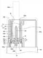
図5及び図6を参照すれば、エアロゾル生成装置1000は、シガレット2000が挿入可能なケース1001と、ケース1001の一側端部1001aから突出し、外部に向かって開放された開口を有する中空状の突出管1020と、端部1031が突出管1020の内部に位置するように、ケース1001に設けられ、電気信号が印加されれば、熱を発生させるヒータ1030と、突出管1020の内側面から延びるラウンド面1040rを備え、ヒータ1030を支持するように突出管1020の内部に設けられるヒータ固定部1040を含む。また、エアロゾル生成装置1000は、突出管1020に結合され、突出管1020から分離されるシガレット支持部4をさらに含む。 Referring to FIGS. 5 and 6, the
図5に図示されたように、シガレット支持部4がケース1001に結合されている状態で、ユーザが手にシガレット支持部4を取って上方に引っ張ればば、ケース1001からシガレット支持部4を分離することができる。 As shown in FIG. 5, when the cigarette support portion 4 is connected to the
図6を参照すれば、突出管1020は、ヒータ1030を取り囲んで保護し、シガレット支持部4が突出管1020に結合されたとき、シガレット支持部4を支持する機能を行う。 Referring to FIG. 6, the protruding
突出管1020は、内部が空いている中空状を有するので、突出管1020は、内部にシガレット支持部4の少なくとも一部が挿入される結合通路1020hを備える。結合通路1020hの上端は、エアロゾル生成装置1000の上側方向に向かって外部で開放される。 Since the protruding
ケース1001には、シガレット2000を加熱する機能を行うヒータ1030が設けられる。ヒータ1030は、上側端部1031が突出管1020の内部に位置するようにケース1001に設けられる。突出管1020にシガレット支持部4が結合された状態でシガレット支持部4にシガレット2000が収容される場合、ヒータ1030の上側端部1031がシガレット2000の端部2000bの底面に挿入される。 The
ヒータ1030は、ケース1001の内部に設けられたバッテリ(図1の1100)と制御部(図1の1200)に電気的に連結される。ヒータ1030の端部1031にシガレット2000が挿入された状態で電気がヒータ1030に供給されれば、ヒータ1030が加熱されることで、シガレット2000が加熱される。 The
図5を参照すれば、シガレット支持部4は、突出管1020の開口を通じて突出管1020の内部の結合通路1020hに挿入される。シガレット支持部4は、突出管1020内に挿入される内筒10と、内筒10を支持する外筒20を備える。 Referring to FIG. 5, the cigarette support portion 4 is inserted into the
図6を参照すれば、シガレット支持部4の外筒20は、略半円筒状を有する外部壁20tから内側に突出し、外部壁20tから離隔された延長支持面26を備える。シガレット支持部4が突出管1020に結合されれば、外部壁20tと延長支持面26との間に突出管1020が挿入されることで、シガレット支持部4と突出管1020との結合状態が安定して保持される。 Referring to FIG. 6, the
上述したようなシガレット支持部4と突出管1020との安定した結合構造によれば、エアロゾル生成装置1000に衝撃による外部振動が加えられても、エアロゾル生成装置1000の構成要素が分離されるか、破損されることを減らすことができる。これにより、エアロゾル生成装置1000を長時間使用する場合にも、良好な耐久性及び安定性を保証することができる。 According to the stable coupling structure of the cigarette support portion 4 and the projecting
また、掃除作業を実施するときには、シガレット支持部4をケース1001から容易に分離することができるので、掃除作業が確実で便利に行われる。 Further, when the cleaning work is performed, the cigarette support portion 4 can be easily separated from the
また、突出管1020は、シガレット2000の端部に外気を直接供給する機能を行う。図5を参照すれば、突出管1020は、突出管1020の内部と外部とを連結する空気ホール1020gと、空気ホール1020gに空気の流れを案内するように、突出管1020の表面に沿って延びる空気流路1020nを備える。 Further, the protruding
空気ホール1020gは、突出管1020の長手方向の中心に対して円周方向に沿って離隔され、複数個が設けられてもよい。空気ホール1020g及び空気流路1020nは、突出管1020の外気が突出管1020の内部に流入されるようにする空気の流れ通路を形成する。 A plurality of
図6を参照すれば、シガレット支持部4が突出管1020に結合されるときには、シガレット支持部4の延長支持面26が突出管1020の内側に挿入される。シガレット支持部4の延長支持面26が突出管1020に沿って下方に移動する間、突出管1020の内部に位置するヒータ1030がシガレット支持部4のヒータ挿入口10bを通過する。 Referring to FIG. 6, when the cigarette support portion 4 is coupled to the
シガレット支持部4が突出管1020に結合された状態では、ヒータ1030の端部1031がシガレット支持部4のヒータ挿入口10bを通過してシガレット支持部4の内部に位置する。したがって、シガレット支持部4が突出管1020に結合された状態シガレット2000がシガレット支持部4に収容される場合ヒータ1030の端部1031がシガレット2000に挿入される。 In a state where the cigarette support portion 4 is coupled to the protruding
エアロゾル生成装置1000のユーザがシガレット2000を収容通路1004hに挿入すれば、シガレット2000がシガレット支持部4に沿って移動する。シガレット支持部4の底にシガレット2000の端部2000bが到逹すれば、シガレット2000を手にしているユーザの手に、底とシガレット2000の端部2000bとが接触する感じが伝達される。したがって、ユーザは、シガレット2000を手に取ってエアロゾル生成装置1000に押し入れる簡単な動作を実施することで、シガレット2000をエアロゾル生成装置1000に簡便に装着することができる。 When the user of the
ユーザがシガレット2000をシガレット支持部4から分離するときには、ユーザがシガレット2000を手で取って回転させつつシガレット2000をシガレット支持部4の外部に抜き取ることができる。ユーザがシガレット2000を手で取って回転させる間、タバコ物質によって互いに付着しているシガレット2000とヒータ1030とが完全に分離される。 When the user separates the
シガレット支持部4からシガレット2000を分離した後、ユーザは、シガレット支持部4の内部の掃除作業を実施することができる。掃除作業を実施するために、ユーザがシガレット支持部4をケース1001から分離するときには、ユーザがシガレット支持部4を手で取ってケース1001の外部にシガレット支持部4を抜き取ることができる。 After separating the
ヒータ固定部1040は、突出管1020の内部に設けられ、ヒータ1030の端部1031が貫通する貫通孔1040bを備える。ヒータ固定部1040は、突出管1020によって取り囲まれるように、ケース1001内に設けられ、突出管1020とヒータ固定部1040は、互いに分離された構成なので、突出管1020とヒータ固定部1040との間には、所定間隔のギャップ(gap)が形成される。 The
一方、ヒータ1030の上側端部1031は、ヒータ固定部1040の貫通孔1040bを通過して上側に突出し、かつ突出管1020のヒータ挿入口10bを通過してシガレット支持部4の内部に位置する。 On the other hand, the
ヒータ挿入口10bの面積は、ヒータ挿入口10bを貫通するヒータ1030の断面積よりも広く形成される。かような構造によって、ヒータ挿入口10bを通じて外部空気が出入りする。 The area of the
突出管1020とシガレット支持部4との間、そしてヒータ固定部1040とシガレット支持部4との間には、内部空間50が形成される。内部空間50の一側は、シガレット支持部4が突出管1020に装着される場合、外部空気が流入される流入通路1004gと連通され、他側には、ヒータ挿入口10bと連通される。 An
かような構造によって、流入通路1004gに流入された外部空気は、シガレット支持部4と突出部1020との間隙に沿って内部空間50に流動し、ユーザの吸入作用によって、内部空間50からヒータ挿入口10bを介してシガレット2000を通って、ユーザに吸入される。 With such a structure, the external air flowing into the
すなわち、シガレット2000が挿入されるシガレット支持部4の内部と内部空間50は、ヒータ1030とヒータ挿入口10bとの間に形成される微細な間隙を通じて互いに連通される。この際、シガレット2000は、加熱されてエアロゾルを発生させるが、それと同時に、エアロゾルの液化も共になされて液状物質がシガレット2000の端部2000bで生成され、ヒータ1030とヒータ挿入口10bとの間に形成される間隙を通じて内部空間50側に漏出される。また、内部空間50に残留するエアロゾルが液化されて突出管1020の内側壁面に滴になり、突出管1020の内側壁面に沿って下方へ流れ下がる。ここで、「液状物質」ということは、シガレット2000の板状葉媒質に含有されている水分またはエアロゾル物質を意味する。 That is, the inside of the cigarette support portion 4 into which the
もし、内部空間50に残留する液状物質が突出管1020とシガレット支持部4との間に形成されるギャップ(gap)に流入される場合、液状物質は、突出管1020の内側壁面に沿ってエアロゾル生成装置1000の内部に侵透し、内部に侵透した液状物質がヒータ1030に電気信号を伝達するバッテリ(図1の1100)や制御部(図1の1200)を濡らす場合、バッテリ1100や制御部120が破損される。 If the liquid substance remaining in the
かような問題点を解決するために、ヒータ固定部1040のラウンド面1040rは、内部空間50に流入される液状物質が突出管1020とヒータ固定部1040との間のギャップを通じてエアロゾル生成装置1000の内部に侵透しないように液状の物質を集める一種の防波堤の役割が行える。 In order to solve such a problem, in the round surface 1040r of the
また、ラウンド面1040rは、内部空間50で生成された液状物質が内部空間50のコーナーに固着せず、ヒータ1030側に伝達されるように補助することもできる。例えば、ラウンド面1040rによってヒータ1030側に伝達された液状物質は、ヒータ1030によって加熱されて、再びエアロゾル化されもする。 Further, the round surface 1040r can assist the liquid substance generated in the
また、エアロゾル生成装置1000は、突出管1020とヒータ固定部1040との間に介在されて、突出管1020とヒータ固定部1040との間のギャップを密閉するシーリング部材1050をさらに含んでもよい。 Further, the
ヒータ固定部1040は、突出管1020との当接面から引入形成されるシーリング溝1040hをさらに備え、シーリング部材1050は、シーリング溝1040hに設けられる。しかし、実施例は、それに限定されず、シーリング部材1050は、突出管1020側に形成されたシーリング溝(図示せず)に設けられてもよい。 The
図面に示された実施例は、シーリング部材1050が円形である場合を描いているが、実施例はそれらに限定されない。シーリング部材1050は、弾性(elastic)材料を含み、突出管1020とヒータ固定部1040との間に形成されるギャップを通じて液状物質がエアロゾル生成装置1000の内部に侵透しないように突出管1020とヒータ固定部1040との間のギャップを密閉する機能を行う一特定形状に限定されない。 The examples shown in the drawings depict the case where the sealing
シーリング部材1050は、もし内部空間50に累積した液状物質がヒータ固定部1040のラウンド面1040rの高さ(a)よりも高く溢れ出て突出管1020とヒータ固定部1040との間に形成されるギャップに沿って流れ落ちる場合にも、液状物質のエアロゾル生成装置1000の内部への侵透を防止して、内部に設けられたバッテリ1100と制御部1200とを保護することができる。 If the liquid substance accumulated in the
図7は、本発明の他の実施例に係わるエアロゾル生成装置の一部構成要素を示す側面断面図である。 FIG. 7 is a side sectional view showing a partial component of the aerosol generator according to another embodiment of the present invention.
図7に図示されたエアロゾル生成装置1000の他の実施例の場合、後述するヒータ固定部2040の構造とシーリング部材2060、2070の設置位置及びベース部2050の結合構造以外の他の構成要素は、図6の説明と同一なので、具体的な説明は省略する。 In the case of another embodiment of the
まず、図7に図示されたヒータ固定部2040について説明すれば、ヒータ固定部2040は、ヒータ2030を支持するように突出管2020内部に設けられるが、突出管2020に接触する面から上側に突出するバンク部材2040pと、突出管2020に接触する面から引入形成されて突出管2020の一部を収容する収容溝2040ha、2040hbを備える。 First, the
ここで、「上側」とは、図面に示されたバンク部材2040pが突出する垂直方向のみならず、水平方向に対して交差する方向も含む意味である。すなわち、バンク部材2040pは、図面に図示されたように垂直方向に突出するが、それらに限定されるものではない。例えば、バンク部材2040pは、上側に向かう斜線(slant)方向にも突出でる。 Here, the "upper side" means not only the vertical direction in which the
かような構造によれば、内部空間50に累積された液状物質が突出管2020とヒータ固定部2040との間のギャップに流入されるとしても、バンク部材2040pによって液状物質のエアロゾル生成装置1000内部への浸透が1次的に防止される。また、収容溝2040hbには、シーリング部材2060が設けられることで、突出管2020とヒータ固定部2040との間のギャップを密閉することができるので、シーリング部材2060によって2次的に液状物質の内部浸透を防止することができる。 According to such a structure, even if the liquid substance accumulated in the
図7によれば、他の実施例に係わるヒータ固定部2040はいずれも2つの収容溝2040ha、2040hbを含むと描写されているが、実施例は、その限りではなく、ヒータ固定部2040は、1つ以上の収容溝を含んでもよい。 According to FIG. 7, it is described that the
一例示として、図7を参照すれば、ヒータ2030に隣接する収容溝2040haには、突出管2020の一部が収容され、ヒータ2030から遠く離れた収容溝2040hbには、シーリング部材2060が設けられるが、それとは反対の構造も可能であり、かつ2つの収容溝2040ha、2040hbにいずれもシーリング部材2060が設けられてもよい。 As an example, referring to FIG. 7, a part of the protruding
一方、図7に図示された他の実施例によるエアロゾル生成装置1000は、ヒータに電気信号を伝達するバッテリ(図1の1100)と制御部(図2の1200)とを取り囲んで支持し、ケース2001の内部に突出管2020と噛み合うように設けられるベース部2050と、突出管2020とベース部2050との間に介在されて突出管2020とベース部2050との間のギャップを密閉するシーリング部材2070をさらに含んでもよい。 On the other hand, the
シーリング部材2070は、図6に図示されたヒータ固定部1040のシーリング溝1040hと共に突出管2020やベース部2050に形成されたシーリング溝(図示せず)に設けられるが、実施例は、それらに限定されるものではない。他の例示として、図7に図示された突出管2020とベース部2050には、シーリング溝が別途に形成されず、シーリング部材2070は、突出管2020とベース部2050との間に圧縮された状態に介在される。 The sealing
すなわち、図6に図示されたシーリング部材1050と同様に、図7に図示されたシーリング部材2060、2070も弾性材料を含んでもよい。すなわち、シーリング部材2060、2070は、突出管2020とヒータ固定部2040との間、突出管2020とベース部2050との間のギャップを密閉して、エアロゾル生成装置1000内部への液状物質の侵透を防止することができる。 That is, like the sealing
上述した実施例に係わる構成と効果に係わる説明は、例示的なものに過ぎず、当該技術分野で通常の知識を有する者であれば、そこから多様な変形及び均等な他の実施例が可能であるという点を理解できるであろう。したがって、発明の真の技術的保護範囲は、特許請求の範囲によって決められねばならない。 The description of the configuration and effects of the above-mentioned examples is merely exemplary, from which any person with ordinary knowledge in the art can make various modifications and even other examples. You can understand that. Therefore, the true technical protection of the invention must be determined by the claims.
前述したような本発明の実施例によれば、液状物質のエアロゾル生成装置内への侵透を防止することができる。 According to the embodiment of the present invention as described above, it is possible to prevent the permeation of the liquid substance into the aerosol generator.
Claims (12)
Translated fromJapanese前記ケースの一側端部から突出し、外部に向かって開放される中空状の突出管と、
端部が前記突出管の内部に位置するように前記ケースに設けられ、電気信号が印加されれば、熱を発生させるヒータと、
前記突出管の内側面から延びるラウンド面を備え、前記ヒータを支持するように前記突出管の内部に設けられるヒータ固定部と、
前記突出管と前記ヒータ固定部との間に介在され、前記突出管と前記ヒータ固定部との間のギャップを密閉するシーリング部材と、を含む、エアロゾル生成装置。A case in which a cigarette can be inserted and a case
A hollow protruding tube that protrudes from one side end of the case and is open to the outside,
A heater provided in the case so that the end is located inside the protruding tube and generates heat when an electric signal is applied.
A heater fixing portion having a round surface extending from the inner surface of the protruding pipe and provided inside the protruding pipe so as to support the heater.
An aerosol generator comprising a sealing member interposed between the protruding pipe and the heater fixing portion and sealing a gap between the protruding pipe and the heater fixing portion.
前記シーリング部材は、前記シーリング溝に設けられる、請求項1に記載のエアロゾル生成装置。The heater fixing portion further includes a sealing groove formed by drawing in from the contact surface with the protruding pipe.
The aerosol generator according to claim 1, wherein the sealing member is provided in the sealing groove.
前記シーリング部材は、前記シーリング溝に設けられる、請求項1に記載のエアロゾル生成装置。The protruding pipe includes a sealing groove formed by drawing in from a contact surface with the heater fixing portion.
The aerosol generator according to claim 1, wherein the sealing member is provided in the sealing groove.
前記ケースの一側端部から突出し、外部に向かって開放される中空状の突出管と、
端部が前記突出管の内部に位置するように前記ケースに設けられ、電気信号が印加されれば、熱を発生させるヒータと、
前記突出管に接触する面から上側に突出するバンク部材を備え、前記ヒータを支持するように前記突出管の内部に設けられるヒータ固定部と、を含む、エアロゾル生成装置。A case in which a cigarette can be inserted and a case
A hollow protruding tube that protrudes from one side end of the case and is open to the outside,
A heater that is provided in the case so that the end is located inside the protruding tube and generates heat when an electric signal is applied.
An aerosol generator comprising a bank member projecting upward from a surface in contact with the protruding pipe and a heater fixing portion provided inside the protruding pipe so as to support the heater.
前記収容溝に設けられ、前記突出管と前記ヒータ固定部との間のギャップを密閉するシーリング部材をさらに含む、請求項5に記載のエアロゾル生成装置。The heater fixing portion is formed by drawing in from a contact surface with the protruding pipe, and includes a storage groove for accommodating a part of the protruding pipe.
The aerosol generating apparatus according to claim 5, further comprising a sealing member provided in the accommodating groove and sealing a gap between the protruding pipe and the heater fixing portion.
前記複数個の収容溝のうち、1つは、前記突出管の一部を収容し、
前記複数個の収容溝のうち、他の1つには、前記シーリング部材が設けられる、請求項6に記載のエアロゾル生成装置。A plurality of the accommodating grooves are formed.
One of the plurality of accommodating grooves accommodates a part of the protruding pipe.
The aerosol generating device according to claim 6, wherein the sealing member is provided in the other one of the plurality of accommodating grooves.
前記ケースの一側端部から上側に突出し、外部に向かって開放される中空状の突出管と、
端部が前記突出管の内部に位置するように前記ケースに設けられ、電気信号が印加されれば、熱を発生させるヒータと、
前記ヒータを支持するように前記ケース内に設けられるヒータ固定部と、
前記ヒータに前記電気信号を伝達するバッテリと制御部とを取り囲んで支持し、前記ケースの内部に前記突出管と噛み合うように設けられるベース部と、
前記突出管と前記ベース部との間に介在され、前記突出管と前記ベース部との間のギャップを密閉するシーリング部材と、
前記突出管と前記ヒータ固定部との間に介在され、前記突出管と前記ヒータ固定部との間のギャップを密閉する第2シーリング部材と、を含む、エアロゾル生成装置。A case in which a cigarette can be inserted and a case
A hollow projecting tube that projects upward from one side end of the case and is open to the outside.
A heater provided in the case so that the end is located inside the protruding tube and generates heat when an electric signal is applied.
A heater fixing portion provided in the case so as to support the heater,
A base portion that surrounds and supports the battery that transmits the electric signal to the heater and the control unit, and is provided inside the case so as to mesh with the protruding pipe.
A sealing member that is interposed between the protruding pipe and the base portion and seals a gap between the protruding pipe and the base portion.
An aerosol generator comprising asecond sealing member interposed between the protruding pipe and the heater fixing portion and sealing a gap between the protruding pipe and the heater fixing portion.
前記シーリング部材は、前記シーリング溝に設けられる、請求項9に記載のエアロゾル生成装置。The protruding pipe includes a sealing groove formed by drawing in from a contact surface with the base portion.
The aerosol generating device according to claim 9, wherein the sealing member is provided in the sealing groove.
前記シーリング部材は、前記シーリング溝に設けられる、請求項9に記載のエアロゾル生成装置。The base portion includes a sealing groove formed by drawing in from a contact surface with the protruding pipe.
The aerosol generating device according to claim 9, wherein the sealing member is provided in the sealing groove.
Priority Applications (2)
| Application Number | Priority Date | Filing Date | Title |
|---|---|---|---|
| JP2021165298AJP7277010B2 (en) | 2017-09-06 | 2021-10-07 | aerosol generator |
| JP2022001512AJP7323657B2 (en) | 2017-09-06 | 2022-01-07 | aerosol generator |
Applications Claiming Priority (5)
| Application Number | Priority Date | Filing Date | Title |
|---|---|---|---|
| KR1020170113954AKR20180070453A (en) | 2016-12-16 | 2017-09-06 | Aerosol generating apparatus |
| KR10-2017-0113954 | 2017-09-06 | ||
| KR10-2018-0063759 | 2018-06-01 | ||
| KR1020180063759AKR102065072B1 (en) | 2016-12-16 | 2018-06-01 | Apparatus for generating aerosols |
| PCT/KR2018/006702WO2019050131A1 (en) | 2017-09-06 | 2018-06-14 | Aerosol generation device |
Related Child Applications (2)
| Application Number | Title | Priority Date | Filing Date |
|---|---|---|---|
| JP2020128350ADivisionJP6796739B2 (en) | 2017-09-06 | 2020-07-29 | Aerosol generator |
| JP2021165298ADivisionJP7277010B2 (en) | 2017-09-06 | 2021-10-07 | aerosol generator |
Publications (2)
| Publication Number | Publication Date |
|---|---|
| JP2020527040A JP2020527040A (en) | 2020-09-03 |
| JP6959429B2true JP6959429B2 (en) | 2021-11-02 |
Family
ID=70977643
Family Applications (8)
| Application Number | Title | Priority Date | Filing Date |
|---|---|---|---|
| JP2020501188AActiveJP6959429B2 (en) | 2017-09-06 | 2018-06-14 | Aerosol generator |
| JP2020501377AActiveJP6963089B2 (en) | 2017-09-06 | 2018-06-15 | Aerosol generator |
| JP2020128350AActiveJP6796739B2 (en) | 2017-09-06 | 2020-07-29 | Aerosol generator |
| JP2020128351AActiveJP6799192B2 (en) | 2017-09-06 | 2020-07-29 | Aerosol generator |
| JP2021165298AActiveJP7277010B2 (en) | 2017-09-06 | 2021-10-07 | aerosol generator |
| JP2021168924AActiveJP7225344B2 (en) | 2017-09-06 | 2021-10-14 | aerosol generator |
| JP2022001512AActiveJP7323657B2 (en) | 2017-09-06 | 2022-01-07 | aerosol generator |
| JP2022001510AActiveJP7277621B2 (en) | 2017-09-06 | 2022-01-07 | aerosol generator |
Family Applications After (7)
| Application Number | Title | Priority Date | Filing Date |
|---|---|---|---|
| JP2020501377AActiveJP6963089B2 (en) | 2017-09-06 | 2018-06-15 | Aerosol generator |
| JP2020128350AActiveJP6796739B2 (en) | 2017-09-06 | 2020-07-29 | Aerosol generator |
| JP2020128351AActiveJP6799192B2 (en) | 2017-09-06 | 2020-07-29 | Aerosol generator |
| JP2021165298AActiveJP7277010B2 (en) | 2017-09-06 | 2021-10-07 | aerosol generator |
| JP2021168924AActiveJP7225344B2 (en) | 2017-09-06 | 2021-10-14 | aerosol generator |
| JP2022001512AActiveJP7323657B2 (en) | 2017-09-06 | 2022-01-07 | aerosol generator |
| JP2022001510AActiveJP7277621B2 (en) | 2017-09-06 | 2022-01-07 | aerosol generator |
Country Status (7)
| Country | Link |
|---|---|
| US (6) | US11647785B2 (en) |
| EP (6) | EP3679813A4 (en) |
| JP (8) | JP6959429B2 (en) |
| CN (3) | CN114766724B (en) |
| ES (1) | ES3037195T3 (en) |
| MY (2) | MY195328A (en) |
| PL (1) | PL3679814T3 (en) |
Families Citing this family (49)
| Publication number | Priority date | Publication date | Assignee | Title |
|---|---|---|---|---|
| KR102604176B1 (en) | 2015-06-26 | 2023-11-17 | 니코벤처스 트레이딩 리미티드 | Apparatus for heating smokable material |
| USD843052S1 (en) | 2015-09-21 | 2019-03-12 | British American Tobacco (Investments) Limited | Aerosol generator |
| TW201742555A (en) | 2016-05-13 | 2017-12-16 | 英美煙草(投資)有限公司 | Device for heating smoking materials (2) |
| TWI780186B (en)* | 2017-07-28 | 2022-10-11 | 瑞士商菲利浦莫里斯製品股份有限公司 | Heater assembly, aerosol-generating device, aerosol-generating system, method of generating an aeroslo, and method of assembling a heater assembly for such a device |
| JP6959429B2 (en) | 2017-09-06 | 2021-11-02 | ケーティー・アンド・ジー・コーポレーション | Aerosol generator |
| DK3750418T3 (en) | 2017-10-30 | 2024-04-02 | Kt & G Corp | AEROSOL GENERATION DEVICE AND METHOD OF CONTROLLING THE SAME |
| WO2019228037A1 (en)* | 2018-05-30 | 2019-12-05 | 深圳御烟实业有限公司 | Aerosol generating apparatus |
| KR102074934B1 (en)* | 2018-06-04 | 2020-02-07 | 주식회사 케이티앤지 | Apparatus for generating aerosols |
| US11399566B2 (en) | 2018-06-05 | 2022-08-02 | Kt&G Corporation | Aerosol generating device |
| KR102414658B1 (en) | 2018-07-05 | 2022-06-29 | 주식회사 케이티앤지 | Cigarrets |
| JP1643249S (en)* | 2018-09-18 | 2019-10-15 | e-cigarette cartridge | |
| JP1643514S (en)* | 2018-09-18 | 2019-10-15 | e-cigarette cartridge | |
| CN209376679U (en)* | 2018-09-28 | 2019-09-13 | 深圳市合元科技有限公司 | baking set |
| USD924473S1 (en)* | 2018-10-15 | 2021-07-06 | Nicoventures Trading Limited | Aerosol generator |
| USD945695S1 (en) | 2018-10-15 | 2022-03-08 | Nicoventures Trading Limited | Aerosol generator |
| USD953613S1 (en) | 2019-03-13 | 2022-05-31 | Nicoventures Trading Limited | Aerosol generator |
| USD905901S1 (en)* | 2019-03-19 | 2020-12-22 | Kt&G Corporation | Electronic cigarette |
| KR102480482B1 (en) | 2019-07-05 | 2022-12-23 | 주식회사 케이티앤지 | Aerosol generating device |
| KR102423895B1 (en) | 2019-11-25 | 2022-07-21 | 주식회사 케이티앤지 | Heater assembly, aerosol generating device and aerosol generating system |
| JP1680417S (en)* | 2019-11-29 | 2021-03-08 | electronic cigarette | |
| JP7403623B2 (en)* | 2020-09-07 | 2023-12-22 | ケーティー アンド ジー コーポレイション | Heater assembly and aerosol generation device including the same |
| JP6890203B1 (en) | 2020-09-30 | 2021-06-18 | 日本たばこ産業株式会社 | Power supply unit of aerosol generator |
| EP3984383B1 (en)* | 2020-10-15 | 2023-08-23 | JT International SA | A smoking article with a heated segment comprising a tobacco product |
| JP1714442S (en) | 2020-10-30 | 2022-05-10 | Smoking aerosol generator | |
| JP1714440S (en) | 2020-10-30 | 2022-05-10 | Smoking aerosol generator | |
| JP1714441S (en) | 2020-10-30 | 2022-05-10 | Smoking aerosol generator | |
| JP1715888S (en) | 2020-10-30 | 2022-05-25 | Smoking aerosol generator | |
| USD990765S1 (en) | 2020-10-30 | 2023-06-27 | Nicoventures Trading Limited | Aerosol generator |
| JP1714443S (en) | 2020-10-30 | 2022-05-10 | Smoking aerosol generator | |
| KR102537975B1 (en) | 2020-11-10 | 2023-05-30 | 주식회사 케이티앤지 | Aerosol generating articles |
| EP4294219B1 (en)* | 2021-02-18 | 2025-04-02 | Philip Morris Products S.A. | Replaceable cartridge for aerosol-generating device with slidable sealing element |
| KR102589104B1 (en)* | 2021-03-05 | 2023-10-12 | 주식회사 케이티앤지 | Device for generating aerosol |
| USD989384S1 (en) | 2021-04-30 | 2023-06-13 | Nicoventures Trading Limited | Aerosol generator |
| CN215837097U (en)* | 2021-05-13 | 2022-02-18 | 深圳雾芯科技有限公司 | Flavor rod and electronic cigarette with same |
| US20220384878A1 (en)* | 2021-06-01 | 2022-12-01 | Shenzhen Smoore Technology Limited | Battery assembly and electronic vaporization device |
| EP4373325A4 (en)* | 2021-07-21 | 2025-05-07 | KT & G Corporation | Aerosol-generating device |
| CN217564930U (en)* | 2021-09-08 | 2022-10-14 | 深圳麦时科技有限公司 | Aerosol generating device and heating assembly thereof |
| US20240423269A1 (en)* | 2021-10-20 | 2024-12-26 | Kt&G Corporation | Aerosol-generating device |
| KR102713767B1 (en)* | 2021-10-29 | 2024-10-07 | 주식회사 케이티앤지 | Device for generating aerosol |
| CN114128923B (en)* | 2021-11-02 | 2024-07-05 | 深圳麦时科技有限公司 | Electronic atomization device and electronic atomization system |
| CN216723136U (en)* | 2021-11-03 | 2022-06-14 | 深圳麦时科技有限公司 | Heating assembly and aerosol generating device |
| KR102764421B1 (en)* | 2021-11-23 | 2025-02-07 | 주식회사 케이티앤지 | Device for generating aerosol |
| KR102713766B1 (en)* | 2022-01-19 | 2024-10-07 | 주식회사 케이티앤지 | Device for generating aerosol |
| KR102816644B1 (en)* | 2022-06-22 | 2025-06-05 | 주식회사 케이티앤지 | Device and method for generating aerosol |
| KR20250077487A (en)* | 2022-09-29 | 2025-05-30 | 필립모리스 프로덕츠 에스.에이. | Aerosol generating device having heater module holder |
| WO2024095386A1 (en)* | 2022-11-02 | 2024-05-10 | 日本たばこ産業株式会社 | Aerosol generation device |
| JPWO2024095387A1 (en) | 2022-11-02 | 2024-05-10 | ||
| CN119923201A (en)* | 2022-11-16 | 2025-05-02 | 菲利普莫里斯生产公司 | Aerosol generating device having a two-piece inner housing |
| EP4388897A1 (en)* | 2022-12-19 | 2024-06-26 | Imperial Tobacco Limited | Heater assembly for an aerosol generating device |
Family Cites Families (351)
| Publication number | Priority date | Publication date | Assignee | Title |
|---|---|---|---|---|
| US2638904A (en) | 1950-04-18 | 1953-05-19 | Amos M Mitchell | Cigarette holder |
| CH310239A (en) | 1953-07-24 | 1955-10-15 | Vautier Freres & Cie Sa | Filter, especially for cigarettes, cigarette holders and pipes. |
| DE3302518A1 (en) | 1983-01-26 | 1984-07-26 | T.R.-Plast GmbH & Co Kunststoff-Verarbeitung, 8430 Neumarkt | Apparatus for cleaning and polishing tobacco pipes |
| US4585014A (en) | 1983-08-01 | 1986-04-29 | Fry Arnold H | Fire inhibiting tubular safety shield for a cigarette type smoking device and combination thereof |
| US4637407A (en) | 1985-02-28 | 1987-01-20 | Cangro Industries, Inc. | Cigarette holder |
| US5144962A (en) | 1989-12-01 | 1992-09-08 | Philip Morris Incorporated | Flavor-delivery article |
| US5591368A (en) | 1991-03-11 | 1997-01-07 | Philip Morris Incorporated | Heater for use in an electrical smoking system |
| US5479948A (en) | 1993-08-10 | 1996-01-02 | Philip Morris Incorporated | Electrical smoking article having continuous tobacco flavor web and flavor cassette therefor |
| US5505214A (en) | 1991-03-11 | 1996-04-09 | Philip Morris Incorporated | Electrical smoking article and method for making same |
| US5249586A (en) | 1991-03-11 | 1993-10-05 | Philip Morris Incorporated | Electrical smoking |
| US5388594A (en) | 1991-03-11 | 1995-02-14 | Philip Morris Incorporated | Electrical smoking system for delivering flavors and method for making same |
| US5240012A (en) | 1991-11-13 | 1993-08-31 | Philip Morris Incorporated | Carbon heat smoking article with reusable body |
| US5465738A (en) | 1992-04-09 | 1995-11-14 | Music City Marketing, Inc. | Smoking system |
| US5369723A (en) | 1992-09-11 | 1994-11-29 | Philip Morris Incorporated | Tobacco flavor unit for electrical smoking article comprising fibrous mat |
| US5499636A (en) | 1992-09-11 | 1996-03-19 | Philip Morris Incorporated | Cigarette for electrical smoking system |
| US5692525A (en) | 1992-09-11 | 1997-12-02 | Philip Morris Incorporated | Cigarette for electrical smoking system |
| CN2146758Y (en) | 1992-12-14 | 1993-11-17 | 毛继元 | Once-used false-proof sealing label |
| US5666977A (en) | 1993-06-10 | 1997-09-16 | Philip Morris Incorporated | Electrical smoking article using liquid tobacco flavor medium delivery system |
| CR4906A (en) | 1993-09-10 | 1994-09-09 | Philip Morris Prod | ELECTRIC SMOKING SYSTEM TO DISTRIBUTE FLAVORS AND METHOD FOR ITS MANUFACTURE |
| CN1131676C (en) | 1994-02-25 | 2003-12-24 | 菲利普莫里斯生产公司 | Electric smoking system and cigarette for delivering cigarette aroma |
| AR002035A1 (en) | 1995-04-20 | 1998-01-07 | Philip Morris Prod | A CIGARETTE, A CIGARETTE AND LIGHTER ADAPTED TO COOPERATE WITH THEMSELVES, A METHOD TO IMPROVE THE DELIVERY OF A SPRAY OF A CIGARETTE, A CONTINUOUS MATERIAL OF TOBACCO, A WORKING CIGARETTE, A MANUFACTURING MANUFACTURING METHOD , A METHOD FOR FORMING A HEATER AND AN ELECTRICAL SYSTEM FOR SMOKING |
| US6040560A (en) | 1996-10-22 | 2000-03-21 | Philip Morris Incorporated | Power controller and method of operating an electrical smoking system |
| US5878752A (en) | 1996-11-25 | 1999-03-09 | Philip Morris Incorporated | Method and apparatus for using, cleaning, and maintaining electrical heat sources and lighters useful in smoking systems and other apparatuses |
| JP2972663B2 (en) | 1997-07-23 | 1999-11-08 | 日本電気データ機器株式会社 | Battery storage structure |
| US5967148A (en) | 1997-10-16 | 1999-10-19 | Philip Morris Incorporated | Lighter actuation system |
| JP3327826B2 (en) | 1997-12-05 | 2002-09-24 | 日本たばこ産業株式会社 | Flavor producing articles and flavor producing instruments |
| RU2130744C1 (en) | 1998-09-09 | 1999-05-27 | Ставрулов Игорь Анатольевич | Tobacco article and method for packaging tobacco articles |
| EP1130982B1 (en) | 1998-11-10 | 2006-11-29 | Philip Morris Products Inc. | Brush cleaning unit for the heater fixture of a smoking device |
| US6053176A (en) | 1999-02-23 | 2000-04-25 | Philip Morris Incorporated | Heater and method for efficiently generating an aerosol from an indexing substrate |
| US6532965B1 (en) | 2001-10-24 | 2003-03-18 | Brown & Williamson Tobacco Corporation | Smoking article using steam as an aerosol-generating source |
| US6615840B1 (en) | 2002-02-15 | 2003-09-09 | Philip Morris Incorporated | Electrical smoking system and method |
| GB0209690D0 (en) | 2002-04-27 | 2002-06-05 | British American Tobacco Co | Improvements relating to smoking articles and smokable filler materials therefor |
| US20050172976A1 (en) | 2002-10-31 | 2005-08-11 | Newman Deborah J. | Electrically heated cigarette including controlled-release flavoring |
| US6810883B2 (en) | 2002-11-08 | 2004-11-02 | Philip Morris Usa Inc. | Electrically heated cigarette smoking system with internal manifolding for puff detection |
| CN1205388C (en) | 2003-01-17 | 2005-06-08 | 安县纸业有限公司 | A kind of sterilization, antibacterial paper |
| CN100367835C (en) | 2003-02-10 | 2008-02-06 | 富士通株式会社 | Shielding member that shields a predetermined member from the outside and electronic equipment having the shielding member |
| US7293565B2 (en)* | 2003-06-30 | 2007-11-13 | Philip Morris Usa Inc. | Electrically heated cigarette smoking system |
| US7392809B2 (en)* | 2003-08-28 | 2008-07-01 | Philip Morris Usa Inc. | Electrically heated cigarette smoking system lighter cartridge dryer |
| JP2006092831A (en) | 2004-09-22 | 2006-04-06 | Harison Toshiba Lighting Corp | Ceramic heater, fixing device, image forming device |
| JP2006320286A (en) | 2005-05-20 | 2006-11-30 | Tokai Corp | Apparatus for heating pseudo-tobacco and pseudo-tobacco |
| CN2857109Y (en) | 2005-12-27 | 2007-01-10 | 深圳市远望谷信息技术股份有限公司 | Anti-tearing electronic label |
| CA2641167A1 (en) | 2006-02-03 | 2007-08-16 | Master Lock Company Llc | User adjustable storage arrangement |
| CN201067079Y (en) | 2006-05-16 | 2008-06-04 | 韩力 | Simulated aerosol inhaler |
| JP2008035742A (en) | 2006-08-03 | 2008-02-21 | British American Tobacco Pacific Corporation | Evaporating apparatus |
| IES20070633A2 (en) | 2006-09-05 | 2008-09-17 | Oglesby & Butler Res & Dev Ltd | A container comprising vaporisable matter for use in a vaporising device for vaporising a vaporisable constituent thereof |
| US7861726B1 (en) | 2006-11-27 | 2011-01-04 | Lukasavitz Steven J | Filtration device for tobacco products |
| CN1973706A (en) | 2006-11-29 | 2007-06-06 | 郭德荣 | Cigarette ash pen |
| EP1964482A1 (en) | 2007-02-28 | 2008-09-03 | Reemtsma Cigarettenfabriken GmbH | Smoking tobacco unit |
| CA2963423C (en) | 2007-03-30 | 2020-07-28 | Philip Morris Products S.A. | Device and method for delivery of a medicament |
| EP1989946A1 (en) | 2007-05-11 | 2008-11-12 | Rauchless Inc. | Smoking device, charging means and method of using it |
| MY150067A (en) | 2007-12-14 | 2013-11-29 | Japan Tobacco Inc | Cigarette filter and filter-tipped cigarette |
| EP2110033A1 (en) | 2008-03-25 | 2009-10-21 | Philip Morris Products S.A. | Method for controlling the formation of smoke constituents in an electrical aerosol generating system |
| EP2110034A1 (en) | 2008-04-17 | 2009-10-21 | Philip Morris Products S.A. | An electrically heated smoking system |
| EP2113178A1 (en) | 2008-04-30 | 2009-11-04 | Philip Morris Products S.A. | An electrically heated smoking system having a liquid storage portion |
| US20090283103A1 (en) | 2008-05-13 | 2009-11-19 | Nielsen Michael D | Electronic vaporizing devices and docking stations |
| KR100965099B1 (en) | 2008-07-07 | 2010-06-22 | (주)휴맥스 | Case fasteners |
| AT507187B1 (en) | 2008-10-23 | 2010-03-15 | Helmut Dr Buchberger | INHALER |
| CN102216526A (en) | 2008-11-12 | 2011-10-12 | 日本烟草产业株式会社 | Rolling paper for low-burning cigarettes |
| EP2201850A1 (en) | 2008-12-24 | 2010-06-30 | Philip Morris Products S.A. | An article including identification information for use in an electrically heated smoking system |
| CN101444335B (en) | 2008-12-31 | 2011-05-25 | 广东中烟工业有限责任公司 | a safe cigarette |
| JP4739433B2 (en) | 2009-02-07 | 2011-08-03 | 和彦 清水 | Smokeless smoking jig |
| CN201491717U (en) | 2009-04-24 | 2010-06-02 | 刘文福 | Environmental protection type electronic smoking set |
| JP2011087569A (en) | 2009-05-15 | 2011-05-06 | Jbs:Kk | Electronic cigarette and charging unit |
| EP2253233A1 (en) | 2009-05-21 | 2010-11-24 | Philip Morris Products S.A. | An electrically heated smoking system |
| KR20090008911U (en) | 2009-06-30 | 2009-09-02 | 황일영 | Sterilizer for electronic cigaret |
| CN101940369A (en) | 2009-07-09 | 2011-01-12 | 宁波博迪电子科技有限公司 | Smoking-type electronic fragrant mist device and manufacturing method thereof |
| US8464726B2 (en) | 2009-08-24 | 2013-06-18 | R.J. Reynolds Tobacco Company | Segmented smoking article with insulation mat |
| CN201467999U (en) | 2009-08-27 | 2010-05-19 | 华健 | Disposable electronic cigarette |
| EP2316286A1 (en) | 2009-10-29 | 2011-05-04 | Philip Morris Products S.A. | An electrically heated smoking system with improved heater |
| GB201001944D0 (en) | 2010-02-05 | 2010-03-24 | Kind Consumer Ltd | A simulated smoking device |
| EP2361516A1 (en) | 2010-02-19 | 2011-08-31 | Philip Morris Products S.A. | Aerosol-generating substrate for smoking articles |
| CA2789362C (en) | 2010-02-24 | 2014-05-27 | Japan Tobacco Inc. | Flavor inhalation pipe |
| AT508244B1 (en) | 2010-03-10 | 2010-12-15 | Helmut Dr Buchberger | INHALATORKOMPONENTE |
| UA102660C2 (en) | 2010-03-25 | 2013-07-25 | Джапан Тобакко Инк. | Cigarette filter with a capsule and a cigarette with such a filter |
| KR20110009632U (en) | 2010-04-05 | 2011-10-12 | 오상택 | Sterilizing and charging apparatus for electronic cigarette |
| KR101791078B1 (en) | 2010-04-16 | 2017-10-30 | 에스케이텔레콤 주식회사 | Video Coding and Decoding Method and Apparatus |
| US9439455B2 (en) | 2010-04-30 | 2016-09-13 | Fontem Holdings 4 B.V. | Electronic smoking device |
| US9149072B2 (en) | 2010-05-06 | 2015-10-06 | R.J. Reynolds Tobacco Company | Segmented smoking article with substrate cavity |
| US9743691B2 (en) | 2010-05-15 | 2017-08-29 | Rai Strategic Holdings, Inc. | Vaporizer configuration, control, and reporting |
| US20110290248A1 (en) | 2010-05-25 | 2011-12-01 | Steven Michael Schennum | Aerosol Generator |
| SMT202000393T1 (en) | 2010-08-24 | 2020-09-10 | Jt Int Sa | Inhalation device including substance usage controls |
| EP2454956A1 (en) | 2010-11-19 | 2012-05-23 | Philip Morris Products S.A. | An electrically heated smoking system comprising at least two units |
| CN102109393B (en) | 2010-11-30 | 2012-05-23 | 中国烟草总公司郑州烟草研究院 | Cigarette ignition temperature distribution detector and automatic control method thereof |
| EP2460422A1 (en) | 2010-12-03 | 2012-06-06 | Philip Morris Products S.A. | An aerosol generating system with provention of condensate leakage |
| EP2460424A1 (en) | 2010-12-03 | 2012-06-06 | Philip Morris Products S.A. | An aerosol generating system with leakage prevention |
| EP2468117A1 (en) | 2010-12-24 | 2012-06-27 | Philip Morris Products S.A. | An aerosol generating system having means for determining depletion of a liquid substrate |
| EP2469969A1 (en) | 2010-12-24 | 2012-06-27 | Philip Morris Products S.A. | Reduced ceramic heating element |
| EP2468118A1 (en) | 2010-12-24 | 2012-06-27 | Philip Morris Products S.A. | An aerosol generating system with means for disabling a consumable |
| US9149586B2 (en)* | 2011-02-07 | 2015-10-06 | Seibo Ping-Cheng SHEN | Herbal vaporization apparatus and method |
| AT510837B1 (en) | 2011-07-27 | 2012-07-15 | Helmut Dr Buchberger | INHALATORKOMPONENTE |
| CN103491815B (en) | 2011-02-11 | 2016-01-20 | 巴特马克有限公司 | Inhalator assembly |
| GB201104475D0 (en) | 2011-03-16 | 2011-04-27 | Filtrona Filter Prod Dev Co | Tobacco smoke filter |
| GB201104788D0 (en) | 2011-03-22 | 2011-05-04 | British American Tobacco Co | Smoking article |
| KR101098112B1 (en) | 2011-03-30 | 2011-12-26 | 한정환 | System to control the electronic cigarette according to the number of smoking and the smoking time |
| KR20120121314A (en) | 2011-04-26 | 2012-11-05 | 하종석 | cartridge of inhalation type anti-smoking preparation and cartridge case for the same |
| KR20120121645A (en)* | 2011-04-27 | 2012-11-06 | 한창희 | Electronic Cigar Without Smoke |
| CN102326869B (en) | 2011-05-12 | 2013-04-03 | 陈志平 | Atomization nozzle of electronic atomization inhaler |
| US9462830B2 (en) | 2011-07-12 | 2016-10-11 | Huizhou Kimree Technology Co., Ltd. | Electronic cigarette |
| PL2551407T3 (en) | 2011-07-28 | 2013-11-29 | Delfortgroup Ag | Oil-resistant filter wrapping paper |
| US9078473B2 (en) | 2011-08-09 | 2015-07-14 | R.J. Reynolds Tobacco Company | Smoking articles and use thereof for yielding inhalation materials |
| ES2596715T3 (en) | 2011-08-12 | 2017-01-11 | Japan Tobacco, Inc. | Drying device and smoking paper making machine that uses the drying device |
| GB201207054D0 (en) | 2011-09-06 | 2012-06-06 | British American Tobacco Co | Heating smokeable material |
| KR20130027909A (en) | 2011-09-08 | 2013-03-18 | 이영인 | Cartridge for electronic cigarette with enhanced inhaling flavor |
| IN2014CN02160A (en) | 2011-09-20 | 2015-05-29 | Reynolds Tobacco Co R | |
| KR102112991B1 (en) | 2011-10-25 | 2020-05-21 | 필립모리스 프로덕츠 에스.에이. | Aerosol generating device with heater assembly |
| SG11201402068YA (en) | 2011-11-07 | 2014-06-27 | Philip Morris Products Sa | Smoking article with colour change segment |
| AU2012342570B2 (en) | 2011-11-21 | 2016-11-24 | Philip Morris Products S.A. | Ejector for an aerosol-generating device |
| AU2012356194A1 (en) | 2011-12-18 | 2014-07-17 | Sis Resources Ltd. | Charging electronic cigarette |
| CN202407082U (en) | 2011-12-23 | 2012-09-05 | 刘秋明 | electronic cigarette nozzle |
| EP2609820A1 (en) | 2011-12-30 | 2013-07-03 | Philip Morris Products S.A. | Detection of aerosol-forming substrate in an aerosol generating device |
| AR089602A1 (en) | 2011-12-30 | 2014-09-03 | Philip Morris Products Sa | AEROSOL GENERATOR ARTICLE FOR USE WITH AN AEROSOL GENERATOR DEVICE |
| PL2797450T3 (en) | 2011-12-30 | 2018-03-30 | Philip Morris Products S.A. | Smoking article with front-plug and method |
| MY170381A (en) | 2011-12-30 | 2019-07-27 | Philip Morris Products Sa | Smoking article with front-plug and aerosol-forming substrate and method |
| EP2609821A1 (en) | 2011-12-30 | 2013-07-03 | Philip Morris Products S.A. | Method and apparatus for cleaning a heating element of aerosol-generating device |
| BR112014012734B1 (en) | 2011-12-30 | 2021-03-02 | Philip Morris Products S.A. | aerosol generation system and method for providing aerosol delivery data to an end user |
| JP6062457B2 (en) | 2011-12-30 | 2017-01-18 | フィリップ・モーリス・プロダクツ・ソシエテ・アノニム | Aerosol generator with airflow detection |
| EP2625974A1 (en) | 2012-02-13 | 2013-08-14 | Philip Morris Products S.A. | Aerosol-generating article having a flavour-generating component |
| EP2797445B1 (en) | 2011-12-30 | 2016-05-04 | Philip Morris Products S.a.s. | Aerosol generating device with improved temperature distribution |
| EP2625975A1 (en) | 2012-02-13 | 2013-08-14 | Philip Morris Products S.A. | Aerosol-generating article having an aerosol-cooling element |
| AR089607A1 (en) | 2012-01-03 | 2014-09-03 | Philip Morris Products Sa | ENERGY SUPPLY SYSTEM FOR A PORTABLE AEROSOL GENERATOR DEVICE |
| CA2862451C (en) | 2012-01-03 | 2020-02-18 | Philip Morris Products S.A. | An aerosol generating device and system with improved airflow |
| HUE030009T2 (en) | 2012-01-03 | 2017-04-28 | Philip Morris Products Sa | Aerosol-generating device and system |
| MX352722B (en) | 2012-01-03 | 2017-12-06 | Philip Morris Products Sa | Non-rolling aerosol-generating device. |
| US9289014B2 (en) | 2012-02-22 | 2016-03-22 | Altria Client Services Llc | Electronic smoking article and improved heater element |
| JP2015107056A (en) | 2012-03-16 | 2015-06-11 | 日本たばこ産業株式会社 | Non-heating type flavor sucker |
| US20130284192A1 (en) | 2012-04-25 | 2013-10-31 | Eyal Peleg | Electronic cigarette with communication enhancements |
| US11517042B2 (en) | 2012-04-25 | 2022-12-06 | Altria Client Services Llc | Digital marketing applications for electronic cigarette users |
| US20130340775A1 (en) | 2012-04-25 | 2013-12-26 | Bernard Juster | Application development for a network with an electronic cigarette |
| GB2502054A (en) | 2012-05-14 | 2013-11-20 | Nicoventures Holdings Ltd | Electronic smoking device |
| US9427023B2 (en) | 2012-06-20 | 2016-08-30 | Huizhou Kimree Technology Co., Ltd., Shenzhen Branch | Electronic cigarette and electronic cigarette device |
| AR091509A1 (en) | 2012-06-21 | 2015-02-11 | Philip Morris Products Sa | ARTICLE TO SMOKE TO BE USED WITH AN INTERNAL HEATING ELEMENT |
| CN204292193U (en) | 2012-07-23 | 2015-04-29 | 惠州市吉瑞科技有限公司 | Electronic cigarette |
| CN104135882B (en) | 2012-07-23 | 2018-02-16 | 惠州市吉瑞科技有限公司 | Electronic cigarette |
| EP2701268A1 (en) | 2012-08-24 | 2014-02-26 | Philip Morris Products S.A. | Portable electronic system including charging device and method of charging a secondary battery |
| AU2012388105B2 (en) | 2012-08-24 | 2017-01-12 | Huizhou Kimree Technology Co., Ltd. | Electronic cigarette apparatus |
| CA2882464C (en) | 2012-08-24 | 2017-07-25 | Kimree Hi-Tech Inc. | Electronic cigarette apparatus |
| EP2732713A4 (en) | 2012-08-31 | 2015-07-22 | Kimree Hi Tech Inc | Electronic cigarette with multiple tastes |
| US9591875B2 (en) | 2012-09-21 | 2017-03-14 | R. J. Reynolds Tobacco Company | Fibrous composite tobacco-containing materials |
| US9386800B2 (en) | 2012-09-21 | 2016-07-12 | R.J. Reynolds Tobacco Company | Fibrous composite tobacco-containing materials |
| CN202774134U (en) | 2012-09-21 | 2013-03-13 | 刘秋明 | Electronic cigarette case and electronic cigarette device |
| US9854841B2 (en) | 2012-10-08 | 2018-01-02 | Rai Strategic Holdings, Inc. | Electronic smoking article and associated method |
| JP2014079229A (en) | 2012-10-17 | 2014-05-08 | Hanasato Kk | Portable smoking tool |
| GB201219540D0 (en) | 2012-10-31 | 2012-12-12 | British American Tobacco Co | A filter for a smoking article |
| KR200466757Y1 (en) | 2012-11-01 | 2013-05-06 | (주)잔티아시아 | Smart electronic cigarette with multifunction control means |
| TWI629007B (en) | 2012-12-21 | 2018-07-11 | Philip Morris Products S. A. | Smoking article comprising an airflow directing element |
| HUE036091T2 (en)* | 2012-12-28 | 2018-06-28 | Philip Morris Products Sa | Heating assembly for an aerosol generating system |
| CN203015840U (en)* | 2013-01-04 | 2013-06-26 | 向之冠 | Electronic cigarette atomizer |
| UA118101C2 (en) | 2013-02-22 | 2018-11-26 | Олтріа Клайєнт Сервісиз Ллк | Electronic smoking article |
| US10031183B2 (en) | 2013-03-07 | 2018-07-24 | Rai Strategic Holdings, Inc. | Spent cartridge detection method and system for an electronic smoking article |
| US9560883B2 (en) | 2013-03-15 | 2017-02-07 | Altria Client Services Llc | Electronic smoking articles |
| US9423152B2 (en) | 2013-03-15 | 2016-08-23 | R. J. Reynolds Tobacco Company | Heating control arrangement for an electronic smoking article and associated system and method |
| KR101498779B1 (en) | 2013-03-19 | 2015-03-06 | 윤성훈 | Charging system of electronic cigarettes capable of wireless charging |
| US20140299137A1 (en) | 2013-04-05 | 2014-10-09 | Johnson Creek Enterprises, LLC | Electronic cigarette and method and apparatus for controlling the same |
| US9629394B2 (en) | 2013-04-09 | 2017-04-25 | Alan Benet Aronie | Portable vaporizer with central pin heater having heat diffuser-mixer blades |
| WO2014166079A1 (en) | 2013-04-10 | 2014-10-16 | 吉瑞高新科技股份有限公司 | Electronic cigarette built in power supply rod |
| CN104106842B (en) | 2013-04-16 | 2019-02-12 | 惠州市吉瑞科技有限公司 | The method of electronic cigarette and processing electronic cigarette smoking data |
| WO2014169467A1 (en)* | 2013-04-18 | 2014-10-23 | Liu Qiuming | Electronic cigarette |
| CN203457802U (en) | 2013-05-07 | 2014-03-05 | 深圳市合元科技有限公司 | Oil-leakage-prevention electronic cigarette atomizer and electronic cigarette |
| ES2670574T3 (en) | 2013-05-20 | 2018-05-31 | Nu Mark Innovations Ltd | Development of applications for a network associated with an electronic cigarette |
| EP2999367B8 (en) | 2013-05-23 | 2020-12-30 | Altria Client Services LLC | Digital marketing application for electronic cigarette users |
| WO2015009903A2 (en) | 2013-07-18 | 2015-01-22 | Quitbit, Inc. | Lighter and method for monitoring smoking behavior |
| KR200469513Y1 (en) | 2013-07-18 | 2013-10-16 | 박일환 | Portable electronic cigarette case having sterilization function |
| GB2518598B (en) | 2013-08-30 | 2016-06-01 | Nicoventures Holdings Ltd | Apparatus with battery power control |
| KR101516304B1 (en)* | 2013-09-12 | 2015-05-04 | 김한기 | Electrical Cigarette |
| EP3222159B1 (en) | 2013-09-30 | 2020-06-17 | Japan Tobacco Inc. | Non-burning type flavor inhaler |
| CN105592736B (en) | 2013-09-30 | 2018-10-16 | 日本烟草产业株式会社 | Non-combustible aroma inhaler |
| US20150100441A1 (en) | 2013-10-04 | 2015-04-09 | Loec, Inc. | Retail engine for electronic smoking device |
| TWI651055B (en)* | 2013-10-08 | 2019-02-21 | 傑提國際公司 | Aerosol transferring adapter for an aerosol generating device and method for transferring aerosol within an aerosol generating device |
| CN203563687U (en) | 2013-11-05 | 2014-04-30 | 湖北中烟工业有限责任公司 | Heat conduction type low-temperature cigarette heat preservation sleeve |
| US10039321B2 (en) | 2013-11-12 | 2018-08-07 | Vmr Products Llc | Vaporizer |
| CN203575658U (en) | 2013-11-28 | 2014-05-07 | 川渝中烟工业有限责任公司 | Device for electrically heating cigarette |
| CN103622162B (en) | 2013-11-28 | 2016-02-03 | 川渝中烟工业有限责任公司 | A kind of pin type electrical heating cigarette system |
| CN203646503U (en) | 2013-11-29 | 2014-06-18 | 刘秋明 | Electronic cigarette device |
| CN203633505U (en) | 2013-11-29 | 2014-06-11 | 深圳市合元科技有限公司 | Atomizer for electronic cigarette and electronic cigarette |
| KR102343546B1 (en) | 2013-12-03 | 2021-12-28 | 필립모리스 프로덕츠 에스.에이. | Aerosol-generating article and electrically operated system incorporating a taggant |
| ES2991810T3 (en) | 2013-12-05 | 2024-12-05 | Philip Morris Products Sa | Aerosol generating article with low resistance airflow path |
| WO2015088744A1 (en) | 2013-12-12 | 2015-06-18 | Meadwestvaco Corporation | Container for a cylindrical object |
| KR101656061B1 (en) | 2013-12-18 | 2016-09-22 | 신종수 | Electronic cigarette |
| SG11201605058YA (en) | 2013-12-20 | 2016-07-28 | Philip Morris Products Sa | Smoking article filter including degradable filter component |
| CN203692545U (en) | 2013-12-28 | 2014-07-09 | 惠州市凯尔文科技有限公司 | Electronic cigarette atomizer and electronic cigarette with same |
| CN203689071U (en) | 2014-01-10 | 2014-07-02 | 刘秋明 | Electronic cigarette case and electronic cigarette case information management system |
| US9974334B2 (en)* | 2014-01-17 | 2018-05-22 | Rai Strategic Holdings, Inc. | Electronic smoking article with improved storage of aerosol precursor compositions |
| JP6273591B2 (en) | 2014-01-20 | 2018-02-07 | フイジョウ キムリー テクノロジー シーオー.、エルティーディー.シェンジェン ブランチ | Battery stick, electronic cigarette, and battery stick assembly method |
| US20150216237A1 (en)* | 2014-01-22 | 2015-08-06 | E-Nicotine Technology, Inc. | Methods and devices for smoking urge relief |
| CN203789137U (en) | 2014-01-26 | 2014-08-27 | 深圳市合元科技有限公司 | Baking type smoke generating device and smoke sucking-in device |
| TWM478798U (en) | 2014-01-28 | 2014-05-21 | Wei-Li Tsai | Smoke blowing device |
| US20150216234A1 (en)* | 2014-02-06 | 2015-08-06 | Esquire Properties Trading Inc. | Electronic cigarette |
| KR20230167768A (en) | 2014-02-10 | 2023-12-11 | 필립모리스 프로덕츠 에스.에이. | Cartridge with a heater assembly for an aerosol-generating system |
| US10015990B2 (en) | 2014-02-10 | 2018-07-10 | Phillip Morris Products S.A. | Aerosol-generating system comprising a device and a cartridge, in which the device ensures electrical contact with the cartridge |
| KR102515717B1 (en) | 2014-02-10 | 2023-03-30 | 필립모리스 프로덕츠 에스.에이. | An aerosol-generating system having a fluid-permeable heater assembly |
| CN203723451U (en)* | 2014-02-20 | 2014-07-23 | 刘秋明 | Electronic cigarette |
| RU2670047C2 (en) | 2014-02-24 | 2018-10-17 | Филип Моррис Продактс С.А. | Filter with improved hardness and filtration efficiency |
| DE202014001718U1 (en) | 2014-02-27 | 2015-05-28 | Xeo Holding GmbH | smoking device |
| GB201413027D0 (en)* | 2014-02-28 | 2014-09-03 | Beyond Twenty Ltd | Beyond 4 |
| US10130119B2 (en) | 2014-02-28 | 2018-11-20 | Beyond Twenty Ltd. | Electronic vaporiser system |
| US9974332B2 (en) | 2014-02-28 | 2018-05-22 | Huizhou Kimree Technology Co., Ltd. Shenzhen Branch | Electronic cigarette charging dock, electronic cigarette case, and method for use thereof |
| EP2915443B1 (en) | 2014-03-03 | 2019-08-14 | Fontem Holdings 1 B.V. | Electronic smoking device |
| US11696604B2 (en) | 2014-03-13 | 2023-07-11 | Rai Strategic Holdings, Inc. | Aerosol delivery device and related method and computer program product for controlling an aerosol delivery device based on input characteristics |
| CN103859606A (en) | 2014-03-14 | 2014-06-18 | 川渝中烟工业有限责任公司 | Layered independent heating low-temperature tobacco flake heater |
| CN103859607B (en)* | 2014-03-18 | 2016-03-30 | 深圳市博迪科技开发有限公司 | There is electronic cigarette packet and the electronic cigarette of magnetic-type charge function |
| US20150272211A1 (en) | 2014-03-25 | 2015-10-01 | Chanseol Chung | Electronic cigarette cover |
| WO2015147657A1 (en) | 2014-03-26 | 2015-10-01 | Hydroxsys Holdings Limited | Durable asymmetric composite membrane |
| PT3125706T (en) | 2014-03-31 | 2018-10-18 | Philip Morris Products Sa | Electrically heated aerosol-generating system |
| CN203986095U (en) | 2014-04-03 | 2014-12-10 | 惠州市吉瑞科技有限公司 | A kind of atomizer and electronic cigarette |
| WO2015155289A1 (en) | 2014-04-10 | 2015-10-15 | Philip Morris Products S.A. | Aerosol-generating device with helix-shaped heater |
| TWI681691B (en) | 2014-04-30 | 2020-01-01 | 瑞士商菲利浦莫里斯製品股份有限公司 | Electrically heated aerosol-generating system, device and method of controlling the same |
| US11147316B2 (en) | 2014-04-30 | 2021-10-19 | Philip Morris Products S.A. | Aerosol generating device with battery indication |
| KR101837885B1 (en) | 2014-05-02 | 2018-03-12 | 니뽄 다바코 산교 가부시키가이샤 | Non-combustion-type flavor inhaler and computer-readable medium |
| CN203814592U (en) | 2014-05-05 | 2014-09-10 | 马福平 | Novel electronic cigarette |
| KR101631286B1 (en) | 2014-05-12 | 2016-06-16 | 신종수 | Electronic cigarette |
| KR102513244B1 (en) | 2014-05-21 | 2023-03-24 | 필립모리스 프로덕츠 에스.에이. | An electrically heated aerosol-generating system with end heater |
| TWI697289B (en) | 2014-05-21 | 2020-07-01 | 瑞士商菲利浦莫里斯製品股份有限公司 | Aerosol-forming article, electrically heated aerosol-generating device and system and method of operating said system |
| TWI669072B (en) | 2014-05-21 | 2019-08-21 | 瑞士商菲利浦莫里斯製品股份有限公司 | Electrically heated aerosol-generating system and cartridge for use in such a system |
| KR200488727Y1 (en) | 2014-05-21 | 2019-03-11 | 석인선 | electronic cigarette |
| DE202014004361U1 (en) | 2014-05-28 | 2015-09-01 | Xeo Holding GmbH | Battery module for a smoke device |
| TWI669073B (en) | 2014-06-24 | 2019-08-21 | 瑞士商菲利浦莫里斯製品股份有限公司 | Aerosol-generating system, aerosol-generating article, aerosol-generating device and method of controlling the reaction stoichiometry |
| CN203943078U (en) | 2014-07-04 | 2014-11-19 | 江苏中烟工业有限责任公司 | A kind of electronic cigarette packet with sterilizing function |
| ES2677543T3 (en)* | 2014-07-11 | 2018-08-03 | Philip Morris Products S.A. | Aerosol generating system comprising a removable heater |
| CN104095295A (en) | 2014-07-18 | 2014-10-15 | 云南中烟工业有限责任公司 | Smoking set with function of electromagnetic induction heating |
| KR20160012329A (en) | 2014-07-23 | 2016-02-03 | 신원국 | Electronic cigarette and control method thereof |
| GB2528710B (en) | 2014-07-24 | 2018-12-26 | Nicoventures Holdings Ltd | E-cigarette re-charging system |
| KR20160015144A (en) | 2014-07-30 | 2016-02-12 | 이충언 | Electronic cigarette |
| CN204070570U (en) | 2014-08-15 | 2015-01-07 | 深圳市合元科技有限公司 | Smoke inhalation device and electronic cigarette |
| GB201414550D0 (en)* | 2014-08-15 | 2014-10-01 | Essentra Filter Products Dev Co Pte Ltd | Smoking article |
| US10765144B2 (en) | 2014-08-21 | 2020-09-08 | Rai Strategic Holdings, Inc. | Aerosol delivery device including a moveable cartridge and related assembly method |
| US9913493B2 (en)* | 2014-08-21 | 2018-03-13 | Rai Strategic Holdings, Inc. | Aerosol delivery device including a moveable cartridge and related assembly method |
| EP4088594B1 (en)* | 2014-09-17 | 2023-09-06 | Fontem Ventures B.V. | Device for storing and vaporizing liquid media |
| ES3027188T3 (en) | 2014-10-02 | 2025-06-13 | Cue Vapor Ltd | Disposable tank electronic cigarette, method of manufacture and method of use |
| JP6666909B2 (en) | 2014-10-17 | 2020-03-18 | フィリップ・モーリス・プロダクツ・ソシエテ・アノニム | Systems and methods for configuring electrical contacts with electrical devices |
| CN204146338U (en) | 2014-10-19 | 2015-02-11 | 何红红 | Electronic cigarette and electronic smoke atomizer |
| KR20160001476U (en) | 2014-10-28 | 2016-05-10 | 하기성 | Electronic cigarette |
| TWI687021B (en) | 2014-10-28 | 2020-03-01 | 瑞士商菲利浦莫里斯製品股份有限公司 | Adaptive battery charging method, charging device, computer program and computer readable storage medium |
| WO2016075746A1 (en) | 2014-11-10 | 2016-05-19 | 日本たばこ産業株式会社 | Non-combusting flavor inhaler and control method |
| WO2016075028A1 (en) | 2014-11-14 | 2016-05-19 | Jt International Sa | Container for an aerosol generating device |
| CN104382237A (en) | 2014-11-14 | 2015-03-04 | 深圳市麦克韦尔科技有限公司 | Electronic cigarette |
| CN204317504U (en) | 2014-12-03 | 2015-05-13 | 深圳市合元科技有限公司 | Cure hot type electrical smoking device |
| CN104544559A (en) | 2014-12-19 | 2015-04-29 | 上海烟草集团有限责任公司 | Tobacco heater |
| CN204444239U (en) | 2014-12-25 | 2015-07-08 | 上海绿馨电子科技有限公司 | A kind of electronic smoke absorber |
| GB201423313D0 (en) | 2014-12-29 | 2015-02-11 | British American Tobacco Co | Heatable unit for apparatus for heating smokable material and method of making a heatable unit |
| CN104489933A (en) | 2014-12-30 | 2015-04-08 | 湖南中烟工业有限责任公司 | Low-temperature roasted electric heating cigarette, heating body and electric heating cigarette circuit |
| KR20160088163A (en) | 2015-01-15 | 2016-07-25 | 주식회사다모아캠 | Potable recharging apparatus for electronic cigarette |
| JP6833701B2 (en) | 2015-01-28 | 2021-02-24 | フィリップ・モーリス・プロダクツ・ソシエテ・アノニム | Aerosol generating article with integrated heating element |
| KR20160096744A (en) | 2015-02-05 | 2016-08-17 | 조우성 | Easy to carry electronic cigarette case |
| CA2974234C (en) | 2015-02-05 | 2023-09-05 | Philip Morris Products S.A. | Aerosol generating device with anchored heater |
| KR102370640B1 (en) | 2015-02-06 | 2022-03-04 | 필립모리스 프로덕츠 에스.에이. | Improved extractor for an aerosol-generating device |
| KR101523088B1 (en) | 2015-02-16 | 2015-05-26 | 전병철 | Electronic Cigarette |
| KR20160108855A (en) | 2015-03-09 | 2016-09-21 | 신동욱 | Electronic cigarette with a smartphone |
| CN106413444A (en) | 2015-03-18 | 2017-02-15 | 惠州市吉瑞科技有限公司 | Method for heating heating wire of electronic cigarette vaporizer and electronic cigarette |
| CN104770878B (en) | 2015-03-23 | 2017-11-24 | 云南中烟工业有限责任公司 | A kind of electric heating type cigarette smoking device with electronic cigarette pumping function |
| CN104856234B (en)* | 2015-03-25 | 2017-11-17 | 延吉长白山科技服务有限公司 | Smoke creating device and the electronic cigarette with the device |
| TWI703936B (en) | 2015-03-27 | 2020-09-11 | 瑞士商菲利浦莫里斯製品股份有限公司 | A paper wrapper for an electrically heated aerosol-generating article |
| CN104799434B (en) | 2015-03-30 | 2017-06-23 | 刘团芳 | A kind of cigarette roaster |
| EP2921065A1 (en) | 2015-03-31 | 2015-09-23 | Philip Morris Products S.a.s. | Extended heating and heating assembly for an aerosol generating system |
| JP6637486B2 (en) | 2015-04-02 | 2020-01-29 | 日本たばこ産業株式会社 | Flavor inhaler |
| CN204763414U (en) | 2015-04-14 | 2015-11-18 | 珠海优德科技有限公司 | Novel electron is atomizer for cigarette |
| EP3533351B1 (en) | 2015-04-15 | 2020-11-18 | Philip Morris Products S.a.s. | Device and method for controlling an electrical heater to limit temperature according to desired temperature profile over time |
| CN104799438A (en) | 2015-04-30 | 2015-07-29 | 云南昆船数码科技有限公司 | Electronic cigarette smoking set heater with low-temperature heating function |
| CN107529832B (en) | 2015-05-01 | 2021-07-20 | 日本烟草产业株式会社 | Non-combustible aroma aspirator, aroma suction source unit and atomization unit |
| KR20160133665A (en) | 2015-05-13 | 2016-11-23 | 김한기 | A Case for an Electronic Cigarette |
| KR101609715B1 (en) | 2015-05-26 | 2016-04-20 | 주식회사 승완 | Management system for electronic cigarette |
| WO2016187803A1 (en) | 2015-05-26 | 2016-12-01 | 惠州市吉瑞科技有限公司深圳分公司 | Battery module and e-cigarette |
| EP3098738A1 (en) | 2015-05-29 | 2016-11-30 | PARI Pharma GmbH | Aerosol nebulizer control device |
| CN204796745U (en)* | 2015-06-01 | 2015-11-25 | 马野 | Novel electron cigarette |
| CN204796750U (en) | 2015-06-19 | 2015-11-25 | 卓尔悦(常州)电子科技有限公司 | Atomizer and aerosol generating device thereof |
| PL3313215T3 (en) | 2015-06-29 | 2019-12-31 | Philip Morris Products S.A. | Cartridge and device for an aerosol-generating system |
| KR20170006253A (en) | 2015-07-07 | 2017-01-17 | 주식회사 케이티앤지 | Electronic cigarette |
| KR101908058B1 (en) | 2015-07-07 | 2018-10-15 | 주식회사 케이티앤지 | Electronic cigarette |
| CN205072064U (en)* | 2015-07-20 | 2016-03-09 | 深圳麦克韦尔股份有限公司 | Tobacco heating device |
| US9888725B2 (en) | 2015-07-28 | 2018-02-13 | Lunatech, Llc | Inhalation puff counter gauge and display system |
| EP3334296B2 (en) | 2015-08-14 | 2023-04-05 | Philip Morris Products S.A. | An electrically operated smoking device including a compact system for identifying smoking articles in the device |
| KR102773883B1 (en) | 2015-08-14 | 2025-02-27 | 필립모리스 프로덕츠 에스.에이. | An electrically operated smoking device including a system for identifying smoking articles in the device |
| US20170055580A1 (en)* | 2015-08-31 | 2017-03-02 | British American Tobacco (Investments) Limited | Apparatus for heating smokable material |
| GB2542018B (en) | 2015-09-01 | 2020-05-20 | Ayr Ltd | Electronic vaporiser system |
| CA2997119C (en) | 2015-09-01 | 2023-10-24 | Beyond Twenty Limited | Electronic vaporiser system |
| CN205018293U (en) | 2015-09-02 | 2016-02-10 | 广州铁路职业技术学院 | Electronics atomizing suction nozzle device |
| UA122793C2 (en) | 2015-09-11 | 2021-01-06 | Філіп Морріс Продактс С.А. | Multi-segment component for an aerosol-generating article |
| CN207653580U (en) | 2015-11-03 | 2018-07-27 | 惠州市吉瑞科技有限公司深圳分公司 | An electronic flue-cured tobacco |
| CN105310115B (en)* | 2015-11-03 | 2018-07-27 | 深圳瀚星翔科技有限公司 | Electronic smoke atomizer |
| CN105342011B (en)* | 2015-11-06 | 2018-06-26 | 浙江中烟工业有限责任公司 | A kind of heating suction unit of solid smoke grenade cigarette |
| CN105342012A (en)* | 2015-11-06 | 2016-02-24 | 浙江中烟工业有限责任公司 | Novel electronic cigarette utilizing solid smoke cartridge |
| CN105341993B (en) | 2015-11-06 | 2017-03-22 | 浙江中烟工业有限责任公司 | Novel electronic cigarette utilizing solid smoke cartridge |
| CN205180371U (en) | 2015-11-18 | 2016-04-27 | 卓尔悦(常州)电子科技有限公司 | Nebulizer and electronic cigarette with same |
| CN205305992U (en)* | 2015-11-19 | 2016-06-15 | 上海绿馨电子科技有限公司 | Quick detachable atomizer |
| CN205337598U (en) | 2015-11-28 | 2016-06-29 | 深圳市合元科技有限公司 | Fog generator and electron cigarette |
| CN205197003U (en)* | 2015-11-28 | 2016-05-04 | 广东中烟工业有限责任公司 | Detachable cigarette heating device |
| CN205456048U (en) | 2015-12-14 | 2016-08-17 | 深圳市合元科技有限公司 | Heating components, atomizers and electronic cigarettes |
| CN105789506B (en) | 2015-12-24 | 2018-04-17 | 深圳瀚星翔科技有限公司 | Electronic cigarette battery |
| JP6458749B2 (en)* | 2016-01-14 | 2019-01-30 | 清水 和彦 | Smokeless smoking equipment |
| WO2017139963A1 (en) | 2016-02-19 | 2017-08-24 | 深圳麦克韦尔股份有限公司 | Electronic atomizing device |
| CN205512358U (en) | 2016-02-29 | 2016-08-31 | 深圳市瑞莱克斯科技有限公司 | Water filtration formula electron cigarette |
| US9936733B2 (en)* | 2016-03-09 | 2018-04-10 | Rai Strategic Holdings, Inc. | Accessory configured to charge an aerosol delivery device and related method |
| CN205648910U (en)* | 2016-03-14 | 2016-10-19 | 深圳市合元科技有限公司 | A cigarette heating device and heating element thereof |
| CN205597118U (en)* | 2016-03-14 | 2016-09-28 | 深圳市合元科技有限公司 | Cigarette heating device and electron cigarette |
| GB2550540B (en) | 2016-03-24 | 2021-09-29 | Nicoventures Trading Ltd | Vapour provision device |
| KR20180020705A (en) | 2016-08-19 | 2018-02-28 | 엘지전자 주식회사 | Mobile terminal |
| WO2017171161A1 (en) | 2016-03-28 | 2017-10-05 | 엘지전자 주식회사 | Mobile terminal |
| US10334882B2 (en) | 2016-04-13 | 2019-07-02 | Md&C Creative Masion Sa | Electronic cigarette |
| CN205831062U (en) | 2016-04-20 | 2016-12-28 | 深圳市新宜康科技有限公司 | The environmental protection electronic cigarette atomizing core of replaceable heater |
| CN105747281B (en) | 2016-05-04 | 2019-04-23 | 深圳市新宜康科技股份有限公司 | Ceramic composite electronic cigarette heating tube and the electronic cigarette atomizing core for using the heating tube |
| CN105837869A (en) | 2016-05-05 | 2016-08-10 | 张小霞 | High-performance mechanical seal ring composite material and preparation technology thereof |
| EP3456213B1 (en) | 2016-05-12 | 2021-02-17 | Hubei China Tobacco Industry Co., Ltd. | Needle-type heater and preparation method thereof, and electrically heated cigarette having same |
| CN105831812A (en) | 2016-05-12 | 2016-08-10 | 湖北中烟工业有限责任公司 | Electrical heating cigarette with portable inserting device |
| CN205728067U (en) | 2016-05-16 | 2016-11-30 | 阳中华 | A kind of can automated cleaning and there is the electronic smoke atomizer of heater |
| CN205658366U (en) | 2016-06-02 | 2016-10-26 | 阳中华 | Cigarette window type atomizer with cigarette window |
| CN105876869B (en) | 2016-06-08 | 2020-02-14 | 卓尔悦欧洲控股有限公司 | Electronic cigarette |
| CN105852223B (en) | 2016-06-13 | 2019-02-12 | 广西中烟工业有限责任公司 | A non-combustion heating cigarette device |
| US10085485B2 (en)* | 2016-07-06 | 2018-10-02 | Rai Strategic Holdings, Inc. | Aerosol delivery device with a reservoir housing and a vaporizer assembly |
| CN205884659U (en) | 2016-07-20 | 2017-01-18 | 贵州中烟工业有限责任公司 | Smoking device |
| CN106037014B (en) | 2016-07-25 | 2019-01-11 | 卓尔悦欧洲控股有限公司 | Electronic cigarette and its control method |
| CN206097720U (en) | 2016-07-31 | 2017-04-12 | 合肥美高时胶粘标签制品有限公司 | Prevent that casing from opening identification tag |
| CN106136332B (en) | 2016-08-26 | 2023-07-04 | 深圳市康泓威科技有限公司 | Electronic cigarette |
| CN106174699B (en) | 2016-08-30 | 2022-11-04 | 云南中烟工业有限责任公司 | A device for automatically ejecting cigarette butts |
| CN206025202U (en) | 2016-08-30 | 2017-03-22 | 云南中烟工业有限责任公司 | Automatic withdraw from device of cigarette butt |
| CN106235417A (en)* | 2016-08-31 | 2016-12-21 | 马野 | A kind of Novel electric cigarette |
| CN206197012U (en) | 2016-09-14 | 2017-05-31 | 深圳市合元科技有限公司 | Electronic smoking set |
| WO2018050449A1 (en) | 2016-09-15 | 2018-03-22 | Philip Morris Products S.A. | Electronic aerosol-generating smoking device |
| CN106376975B (en) | 2016-09-18 | 2023-10-31 | 上海烟草集团有限责任公司 | Aerosol generating device and method of using the same |
| CN206284388U (en)* | 2016-09-23 | 2017-06-30 | 卓尔悦欧洲控股有限公司 | A kind of electronic cigarette |
| CN106418715A (en)* | 2016-11-04 | 2017-02-22 | 申敏良 | Ceramic atomizing head |
| CN206472849U (en) | 2016-12-06 | 2017-09-08 | 上海绿馨电子科技有限公司 | A kind of low temperature non-burning electronic smoking set |
| US10130124B2 (en) | 2016-12-06 | 2018-11-20 | Shanghai Green Vaper Technology Co., Ltd. | Low temperature heat not burn electronic cigarette |
| CN207836767U (en) | 2016-12-16 | 2018-09-11 | 韩国烟草人参公社 | Aerosol generates equipment |
| KR20180070451A (en) | 2016-12-16 | 2018-06-26 | 주식회사 케이티앤지 | Heater and system for heating an aerosol generating substrate |
| KR20180070457A (en) | 2016-12-16 | 2018-06-26 | 주식회사 케이티앤지 | Aerosol generating apparatus |
| RU2750465C2 (en) | 2016-12-16 | 2021-06-28 | Кей Ти Энд Джи Корпорейшн | Aerosol-generating apparatus |
| KR102138873B1 (en) | 2016-12-16 | 2020-07-29 | 주식회사 케이티앤지 | Aerosols generating system for pre-heating the heater |
| CN206443202U (en) | 2016-12-19 | 2017-08-29 | 湖南中烟工业有限责任公司 | Mix cigarette bullet and mixing low temp cigarette |
| CN206354445U (en)* | 2016-12-21 | 2017-07-28 | 欧俊彪 | Separate type dust cap |
| CN206312988U (en) | 2016-12-26 | 2017-07-07 | 深圳市博迪科技开发有限公司 | The electronic cigarette battery and electronic cigarette of a kind of hiding screw |
| CN106473233A (en) | 2016-12-29 | 2017-03-08 | 上海烟草集团有限责任公司 | Electronic smoking set and its excessively suction indicating means |
| CN206443214U (en)* | 2017-02-07 | 2017-08-29 | 湖南中烟工业有限责任公司 | Bakee atomization mixing smoking set |
| CN106723384A (en)* | 2017-02-28 | 2017-05-31 | 深圳葆威道科技有限公司 | A kind of flue-cured tobacco electronic cigarette |
| CN106880086B (en)* | 2017-04-07 | 2023-07-25 | 云南中烟工业有限责任公司 | A kind of mixed smoke of electronic cigarette and low-temperature flue-cured tobacco |
| JP6930687B2 (en) | 2017-04-11 | 2021-09-01 | ケーティー・アンド・ジー・コーポレーション | Aerosol generator |
| GB201705888D0 (en) | 2017-04-12 | 2017-05-24 | British American Tobacco Investments Ltd | Apparatus for volatilising smokable material and a smoking article |
| CN106858726B (en) | 2017-04-20 | 2018-06-19 | 深圳市卓力能电子有限公司 | A kind of burning tobacco electronic cigarette Cooker structure |
| CN106901404A (en)* | 2017-04-24 | 2017-06-30 | 云南中烟工业有限责任公司 | A kind of slip lid starts formula Bidirectional heating low-temperature bake smoking set |
| CN106912985A (en)* | 2017-04-24 | 2017-07-04 | 云南中烟工业有限责任公司 | A kind of smoking set for having tobacco tar atomization and low-temperature bake function concurrently |
| CN107080292B (en) | 2017-05-24 | 2024-03-01 | 惠州市新泓威科技有限公司 | Electronic smoking set for assisting smoking |
| TWI780186B (en)* | 2017-07-28 | 2022-10-11 | 瑞士商菲利浦莫里斯製品股份有限公司 | Heater assembly, aerosol-generating device, aerosol-generating system, method of generating an aeroslo, and method of assembling a heater assembly for such a device |
| RU2737441C1 (en) | 2017-08-09 | 2020-11-30 | Филип Моррис Продактс С.А. | Aerosol-generating device with induction heater and movable components |
| JP6959429B2 (en) | 2017-09-06 | 2021-11-02 | ケーティー・アンド・ジー・コーポレーション | Aerosol generator |
| KR102047885B1 (en) | 2017-09-11 | 2019-11-22 | 엘지전자 주식회사 | Method for receiving ssb according to synchronization raster and user equipment |
| US10660370B2 (en)* | 2017-10-12 | 2020-05-26 | Rai Strategic Holdings, Inc. | Aerosol delivery device including a control body, an atomizer body, and a cartridge and related methods |
| WO2019095268A1 (en) | 2017-11-17 | 2019-05-23 | 惠州市吉瑞科技有限公司深圳分公司 | Atomizing assembly and electronic cigarette |
| US20200221778A1 (en)* | 2017-12-02 | 2020-07-16 | Michael Trzecieski | Vaporizer device and system |
| JP7680121B2 (en)* | 2017-12-22 | 2025-05-20 | フィリップ・モーリス・プロダクツ・ソシエテ・アノニム | Aerosol generator with an easy-to-clean heated chamber |
| US20190357593A1 (en)* | 2018-05-25 | 2019-11-28 | Acoustic Arc International Limited | Electronic Cigarette |
| US20200323269A1 (en)* | 2018-08-17 | 2020-10-15 | Shenzhen Relx Technology Co., Ltd. | Vaporization device and method thereof |
| EP3945894B1 (en)* | 2019-04-04 | 2025-02-12 | Nicoventures Trading Limited | Method of assembly and apparatus for heating aerosolisable material |
| CN110483986A (en) | 2019-08-28 | 2019-11-22 | 贵州省冶金化工研究所 | A kind of recoverying and utilizing method of selective laser sintering more than 12 powder of nylon |
- 2018
- 2018-06-14JPJP2020501188Apatent/JP6959429B2/enactiveActive
- 2018-06-14MYMYPI2020001219Apatent/MY195328A/enunknown
- 2018-06-14CNCN202111491697.3Apatent/CN114766724B/enactiveActive
- 2018-06-14CNCN202010756239.7Apatent/CN111838772B/enactiveActive
- 2018-06-14USUS16/644,730patent/US11647785B2/enactiveActive
- 2018-06-14EPEP18853434.1Apatent/EP3679813A4/enactivePending
- 2018-06-14EPEP20188792.4Apatent/EP3753423A1/enactivePending
- 2018-06-14EPEP21209164.9Apatent/EP3997993A1/enactivePending
- 2018-06-15MYMYPI2020001220Apatent/MY195322A/enunknown
- 2018-06-15USUS16/644,654patent/US11344062B2/enactiveActive
- 2018-06-15EPEP18854661.8Apatent/EP3679814B1/enactiveActive
- 2018-06-15CNCN202111492624.6Apatent/CN114271542A/enactivePending
- 2018-06-15ESES18854661Tpatent/ES3037195T3/enactiveActive
- 2018-06-15PLPL18854661.8Tpatent/PL3679814T3/enunknown
- 2018-06-15EPEP20188926.8Apatent/EP3750412A3/enactivePending
- 2018-06-15EPEP21210402.0Apatent/EP3987949A1/enactivePending
- 2018-06-15JPJP2020501377Apatent/JP6963089B2/enactiveActive
- 2020
- 2020-07-29USUS16/942,356patent/US12063961B2/enactiveActive
- 2020-07-29JPJP2020128350Apatent/JP6796739B2/enactiveActive
- 2020-07-29USUS16/942,481patent/US11259567B2/enactiveActive
- 2020-07-29JPJP2020128351Apatent/JP6799192B2/enactiveActive
- 2021
- 2021-10-07JPJP2021165298Apatent/JP7277010B2/enactiveActive
- 2021-10-14JPJP2021168924Apatent/JP7225344B2/enactiveActive
- 2021-11-23USUS17/533,783patent/US11730195B2/enactiveActive
- 2021-11-24USUS17/534,847patent/US11937631B2/enactiveActive
- 2022
- 2022-01-07JPJP2022001512Apatent/JP7323657B2/enactiveActive
- 2022-01-07JPJP2022001510Apatent/JP7277621B2/enactiveActive
Also Published As
Similar Documents
| Publication | Publication Date | Title |
|---|---|---|
| JP6796739B2 (en) | Aerosol generator | |
| KR102065072B1 (en) | Apparatus for generating aerosols | |
| JP6951032B2 (en) | Aerosol generator | |
| JP6840883B2 (en) | Aerosol generator | |
| KR102078262B1 (en) | Apparatus for generating aerorols | |
| RU2728109C1 (en) | Evaporator and aerosol generation device comprising such evaporator | |
| JP7275194B2 (en) | aerosol generator | |
| CN110891438B (en) | Aerosol generating device | |
| KR102041904B1 (en) | Smoking apparatus for electrically heated tobacco power |
Legal Events
| Date | Code | Title | Description |
|---|---|---|---|
| A621 | Written request for application examination | Free format text:JAPANESE INTERMEDIATE CODE: A621 Effective date:20200110 | |
| A131 | Notification of reasons for refusal | Free format text:JAPANESE INTERMEDIATE CODE: A131 Effective date:20201201 | |
| A521 | Request for written amendment filed | Free format text:JAPANESE INTERMEDIATE CODE: A523 Effective date:20210202 | |
| A131 | Notification of reasons for refusal | Free format text:JAPANESE INTERMEDIATE CODE: A131 Effective date:20210420 | |
| A521 | Request for written amendment filed | Free format text:JAPANESE INTERMEDIATE CODE: A523 Effective date:20210712 | |
| TRDD | Decision of grant or rejection written | ||
| A01 | Written decision to grant a patent or to grant a registration (utility model) | Free format text:JAPANESE INTERMEDIATE CODE: A01 Effective date:20210907 | |
| A61 | First payment of annual fees (during grant procedure) | Free format text:JAPANESE INTERMEDIATE CODE: A61 Effective date:20211007 | |
| R150 | Certificate of patent or registration of utility model | Ref document number:6959429 Country of ref document:JP Free format text:JAPANESE INTERMEDIATE CODE: R150 | |
| R250 | Receipt of annual fees | Free format text:JAPANESE INTERMEDIATE CODE: R250 |