JP6958865B2 - Toric intraocular lens and intraocular lens insertion device - Google Patents
Toric intraocular lens and intraocular lens insertion deviceDownload PDFInfo
- Publication number
- JP6958865B2 JP6958865B2JP2018510672AJP2018510672AJP6958865B2JP 6958865 B2JP6958865 B2JP 6958865B2JP 2018510672 AJP2018510672 AJP 2018510672AJP 2018510672 AJP2018510672 AJP 2018510672AJP 6958865 B2JP6958865 B2JP 6958865B2
- Authority
- JP
- Japan
- Prior art keywords
- lens
- intraocular lens
- toric intraocular
- plunger
- toric
- Prior art date
- Legal status (The legal status is an assumption and is not a legal conclusion. Google has not performed a legal analysis and makes no representation as to the accuracy of the status listed.)
- Active
Links
Images


Classifications
- A—HUMAN NECESSITIES
- A61—MEDICAL OR VETERINARY SCIENCE; HYGIENE
- A61F—FILTERS IMPLANTABLE INTO BLOOD VESSELS; PROSTHESES; DEVICES PROVIDING PATENCY TO, OR PREVENTING COLLAPSING OF, TUBULAR STRUCTURES OF THE BODY, e.g. STENTS; ORTHOPAEDIC, NURSING OR CONTRACEPTIVE DEVICES; FOMENTATION; TREATMENT OR PROTECTION OF EYES OR EARS; BANDAGES, DRESSINGS OR ABSORBENT PADS; FIRST-AID KITS
- A61F2/00—Filters implantable into blood vessels; Prostheses, i.e. artificial substitutes or replacements for parts of the body; Appliances for connecting them with the body; Devices providing patency to, or preventing collapsing of, tubular structures of the body, e.g. stents
- A61F2/02—Prostheses implantable into the body
- A61F2/14—Eye parts, e.g. lenses or corneal implants; Artificial eyes
- A61F2/16—Intraocular lenses
- A61F2/1662—Instruments for inserting intraocular lenses into the eye
- A61F2/167—Instruments for inserting intraocular lenses into the eye with pushable plungers
- A—HUMAN NECESSITIES
- A61—MEDICAL OR VETERINARY SCIENCE; HYGIENE
- A61F—FILTERS IMPLANTABLE INTO BLOOD VESSELS; PROSTHESES; DEVICES PROVIDING PATENCY TO, OR PREVENTING COLLAPSING OF, TUBULAR STRUCTURES OF THE BODY, e.g. STENTS; ORTHOPAEDIC, NURSING OR CONTRACEPTIVE DEVICES; FOMENTATION; TREATMENT OR PROTECTION OF EYES OR EARS; BANDAGES, DRESSINGS OR ABSORBENT PADS; FIRST-AID KITS
- A61F2/00—Filters implantable into blood vessels; Prostheses, i.e. artificial substitutes or replacements for parts of the body; Appliances for connecting them with the body; Devices providing patency to, or preventing collapsing of, tubular structures of the body, e.g. stents
- A61F2/02—Prostheses implantable into the body
- A61F2/14—Eye parts, e.g. lenses or corneal implants; Artificial eyes
- A61F2/16—Intraocular lenses
- A61F2/1613—Intraocular lenses having special lens configurations, e.g. multipart lenses; having particular optical properties, e.g. pseudo-accommodative lenses, lenses having aberration corrections, diffractive lenses, lenses for variably absorbing electromagnetic radiation, lenses having variable focus
- A61F2/1637—Correcting aberrations caused by inhomogeneities; correcting intrinsic aberrations, e.g. of the cornea, of the surface of the natural lens, aspheric, cylindrical, toric lenses
- A61F2/1645—Toric lenses
- A—HUMAN NECESSITIES
- A61—MEDICAL OR VETERINARY SCIENCE; HYGIENE
- A61F—FILTERS IMPLANTABLE INTO BLOOD VESSELS; PROSTHESES; DEVICES PROVIDING PATENCY TO, OR PREVENTING COLLAPSING OF, TUBULAR STRUCTURES OF THE BODY, e.g. STENTS; ORTHOPAEDIC, NURSING OR CONTRACEPTIVE DEVICES; FOMENTATION; TREATMENT OR PROTECTION OF EYES OR EARS; BANDAGES, DRESSINGS OR ABSORBENT PADS; FIRST-AID KITS
- A61F2/00—Filters implantable into blood vessels; Prostheses, i.e. artificial substitutes or replacements for parts of the body; Appliances for connecting them with the body; Devices providing patency to, or preventing collapsing of, tubular structures of the body, e.g. stents
- A61F2/02—Prostheses implantable into the body
- A61F2/14—Eye parts, e.g. lenses or corneal implants; Artificial eyes
- A61F2/16—Intraocular lenses
- A61F2/1662—Instruments for inserting intraocular lenses into the eye
- A61F2/1672—Instruments for inserting intraocular lenses into the eye with a two-stage plunger, e.g. rotatable and pushable or rotatable at different speeds
- A—HUMAN NECESSITIES
- A61—MEDICAL OR VETERINARY SCIENCE; HYGIENE
- A61F—FILTERS IMPLANTABLE INTO BLOOD VESSELS; PROSTHESES; DEVICES PROVIDING PATENCY TO, OR PREVENTING COLLAPSING OF, TUBULAR STRUCTURES OF THE BODY, e.g. STENTS; ORTHOPAEDIC, NURSING OR CONTRACEPTIVE DEVICES; FOMENTATION; TREATMENT OR PROTECTION OF EYES OR EARS; BANDAGES, DRESSINGS OR ABSORBENT PADS; FIRST-AID KITS
- A61F2/00—Filters implantable into blood vessels; Prostheses, i.e. artificial substitutes or replacements for parts of the body; Appliances for connecting them with the body; Devices providing patency to, or preventing collapsing of, tubular structures of the body, e.g. stents
- A61F2/02—Prostheses implantable into the body
- A61F2/14—Eye parts, e.g. lenses or corneal implants; Artificial eyes
- A61F2/16—Intraocular lenses
- A61F2/1662—Instruments for inserting intraocular lenses into the eye
- A61F2/1678—Instruments for inserting intraocular lenses into the eye with a separate cartridge or other lens setting part for storage of a lens, e.g. preloadable for shipping
- A—HUMAN NECESSITIES
- A61—MEDICAL OR VETERINARY SCIENCE; HYGIENE
- A61F—FILTERS IMPLANTABLE INTO BLOOD VESSELS; PROSTHESES; DEVICES PROVIDING PATENCY TO, OR PREVENTING COLLAPSING OF, TUBULAR STRUCTURES OF THE BODY, e.g. STENTS; ORTHOPAEDIC, NURSING OR CONTRACEPTIVE DEVICES; FOMENTATION; TREATMENT OR PROTECTION OF EYES OR EARS; BANDAGES, DRESSINGS OR ABSORBENT PADS; FIRST-AID KITS
- A61F2/00—Filters implantable into blood vessels; Prostheses, i.e. artificial substitutes or replacements for parts of the body; Appliances for connecting them with the body; Devices providing patency to, or preventing collapsing of, tubular structures of the body, e.g. stents
- A61F2/02—Prostheses implantable into the body
- A61F2/14—Eye parts, e.g. lenses or corneal implants; Artificial eyes
- A61F2/16—Intraocular lenses
- A61F2/1662—Instruments for inserting intraocular lenses into the eye
- A—HUMAN NECESSITIES
- A61—MEDICAL OR VETERINARY SCIENCE; HYGIENE
- A61F—FILTERS IMPLANTABLE INTO BLOOD VESSELS; PROSTHESES; DEVICES PROVIDING PATENCY TO, OR PREVENTING COLLAPSING OF, TUBULAR STRUCTURES OF THE BODY, e.g. STENTS; ORTHOPAEDIC, NURSING OR CONTRACEPTIVE DEVICES; FOMENTATION; TREATMENT OR PROTECTION OF EYES OR EARS; BANDAGES, DRESSINGS OR ABSORBENT PADS; FIRST-AID KITS
- A61F2/00—Filters implantable into blood vessels; Prostheses, i.e. artificial substitutes or replacements for parts of the body; Appliances for connecting them with the body; Devices providing patency to, or preventing collapsing of, tubular structures of the body, e.g. stents
- A61F2/02—Prostheses implantable into the body
- A61F2/14—Eye parts, e.g. lenses or corneal implants; Artificial eyes
- A61F2/16—Intraocular lenses
- A61F2002/1681—Intraocular lenses having supporting structure for lens, e.g. haptics
- A61F2002/1683—Intraocular lenses having supporting structure for lens, e.g. haptics having filiform haptics
- A61F2002/1686—Securing a filiform haptic to a lens body
- A—HUMAN NECESSITIES
- A61—MEDICAL OR VETERINARY SCIENCE; HYGIENE
- A61F—FILTERS IMPLANTABLE INTO BLOOD VESSELS; PROSTHESES; DEVICES PROVIDING PATENCY TO, OR PREVENTING COLLAPSING OF, TUBULAR STRUCTURES OF THE BODY, e.g. STENTS; ORTHOPAEDIC, NURSING OR CONTRACEPTIVE DEVICES; FOMENTATION; TREATMENT OR PROTECTION OF EYES OR EARS; BANDAGES, DRESSINGS OR ABSORBENT PADS; FIRST-AID KITS
- A61F2250/00—Special features of prostheses classified in groups A61F2/00 - A61F2/26 or A61F2/82 or A61F9/00 or A61F11/00 or subgroups thereof
- A61F2250/0058—Additional features; Implant or prostheses properties not otherwise provided for
- A61F2250/0096—Markers and sensors for detecting a position or changes of a position of an implant, e.g. RF sensors, ultrasound markers
- A61F2250/0097—Visible markings, e.g. indicia
Landscapes
- Health & Medical Sciences (AREA)
- Ophthalmology & Optometry (AREA)
- Cardiology (AREA)
- Oral & Maxillofacial Surgery (AREA)
- Transplantation (AREA)
- Engineering & Computer Science (AREA)
- Biomedical Technology (AREA)
- Heart & Thoracic Surgery (AREA)
- Vascular Medicine (AREA)
- Life Sciences & Earth Sciences (AREA)
- Animal Behavior & Ethology (AREA)
- General Health & Medical Sciences (AREA)
- Public Health (AREA)
- Veterinary Medicine (AREA)
- Prostheses (AREA)
- Eyeglasses (AREA)
Description
Translated fromJapanese本発明は、トーリック眼内レンズおよび眼内レンズ挿入器具に関する。 The present invention relates to a toric intraocular lens and an intraocular lens insertion device.
白内障治療においてヒト混濁水晶体の置換や屈折の補正のために水晶体の代用として挿入される眼内レンズが実用に供されている。角膜乱視を有する患者が白内障手術を受ける場合、乱視矯正可能な眼内レンズ、いわゆるトーリック眼内レンズが挿入される場合がある。トーリック眼内レンズを患者の眼球に挿入する場合、患者の角膜の乱視軸と眼内レンズのトーリック軸を一致させる必要がある。 In the treatment of cataracts, an intraocular lens inserted as a substitute for the crystalline lens for replacement of the human opaque crystalline lens and correction of refraction has been put into practical use. When a patient with corneal astigmatism undergoes cataract surgery, an intraocular lens capable of correcting astigmatism, a so-called toric intraocular lens, may be inserted. When inserting a toric intraocular lens into the patient's eyeball, it is necessary to align the astigmatic axis of the patient's cornea with the toric axis of the intraocular lens.
従来、トーリック眼内レンズには、トーリック軸を示すマーキングが施されている。トーリック眼内レンズは、所定の屈折力を有するレンズ本体と、レンズ本体に連結された、レンズ本体を眼球内で保持するための支持部とを備える。トーリック軸を示すマーキングは、レンズ本体において支持部との接合部付近に施される。あるいは、眼内レンズ挿入器具を用いてトーリック眼内レンズを患者の眼球内に押し出すことを想定して、眼内レンズ挿入器具によるトーリック眼内レンズの押し出し時に、押し出し方向とトーリック眼内レンズの弱主経線が平行になるように、トーリック眼内レンズのレンズ本体と支持部とが構成される(例えば特許文献1)。 Conventionally, the toric intraocular lens is marked to indicate the toric axis. The toric intraocular lens includes a lens body having a predetermined refractive power and a support portion connected to the lens body for holding the lens body in the eyeball. The marking indicating the toric axis is made in the vicinity of the joint portion with the support portion in the lens body. Alternatively, assuming that the toric intraocular lens is pushed into the patient's eyeball using the intraocular lens insertion device, the pushing direction and the weakness of the toric intraocular lens when the toric intraocular lens is pushed out by the intraocular lens insertion device. The lens body and the support portion of the toric intraocular lens are configured so that the main meridian lines are parallel (for example, Patent Document 1).
トーリック眼内レンズのレンズ本体と支持部とが同一の素材で製造される、いわゆるワンピース型のトーリック眼内レンズの場合、支持部の強度を高めるために、レンズ本体と支持部との接合部が他の部分に比べて厚くなる傾向がある。この場合、眼内レンズ挿入器具のトーリック眼内レンズが射出される開口部は小径であるため、厚い接合部が眼内レンズ挿入器具内におけるトーリック眼内レンズの移動に支障をきたさないようにする必要がある。したがって、トーリック眼内レンズの押し出し方向に対する支持部の位置が適切な位置になるよう、レンズ本体と支持部の相対位置などを決定する必要がある。また、トーリック眼内レンズのレンズ本体の光軸方向の断面積は、弱主経線方向と強主経線方向とで異なり、弱主経線方向のレンズ本体の厚さは強主経線方向のレンズ本体の厚さに比べて厚くなる。したがって、眼内レンズ挿入器具内におけるトーリック眼内レンズの移動に支障をきたさないように、トーリック眼内レンズの押し出し方向に対するレンズ本体の弱主経線方向と強主経線方向の相対位置を決定する必要もある。 In the case of a so-called one-piece toric intraocular lens in which the lens body and the support portion of the toric intraocular lens are manufactured of the same material, the joint portion between the lens body and the support portion is formed in order to increase the strength of the support portion. It tends to be thicker than other parts. In this case, since the opening through which the toric intraocular lens of the intraocular lens insertion device is ejected has a small diameter, the thick joint should not interfere with the movement of the toric intraocular lens in the intraocular lens insertion device. There is a need. Therefore, it is necessary to determine the relative position of the lens body and the support portion so that the position of the support portion with respect to the extrusion direction of the toric intraocular lens becomes an appropriate position. In addition, the cross-sectional area of the lens body of the toric intraocular lens in the optical axis direction differs between the weak main meridian direction and the strong main meridian direction, and the thickness of the lens body in the weak main meridian direction is that of the lens body in the strong main meridian direction. It becomes thicker than the thickness. Therefore, it is necessary to determine the relative positions of the weak main meridian direction and the strong main meridian direction of the lens body with respect to the extrusion direction of the toric intraocular lens so as not to hinder the movement of the toric intraocular lens in the intraocular lens insertion device. There is also.
しかしながら、上記のトーリック眼内レンズにおいて、レンズ本体の支持部との接合部付近にトーリック軸を示すマーキングを付与することは、接合部とレンズ本体の弱主経線部分とが連結することを意味する。すなわち、厚い接合部と弱主経線部分とが連結されるため、トーリック眼内レンズ全体における厚さのバランスが悪くなる。このように厚い部分がある方向(この場合は、弱主経線方向)に偏ってトーリック眼内レンズが構成されると、眼内レンズ挿入器具のトーリック眼内レンズ押し出し部材(プランジャー)の先端が、トーリック眼内レンズを押し出す際に、トーリック眼内レンズの薄い部分へ逃げるような振る舞いをするために、安定したトーリック眼内レンズの押し出しが妨げられる可能性がある。 However, in the above-mentioned toric intraocular lens, adding a marking indicating the toric axis in the vicinity of the joint portion with the support portion of the lens body means that the joint portion and the weak main meridian portion of the lens body are connected. .. That is, since the thick joint portion and the weak main meridian portion are connected, the thickness balance in the entire toric intraocular lens becomes poor. When the toric intraocular lens is configured in such a direction with a thick portion (in this case, the weak main meridian direction), the tip of the toric intraocular lens extrusion member (plunger) of the intraocular lens insertion device becomes , When the toric intraocular lens is extruded, it behaves as if it escapes to a thin part of the toric intraocular lens, which may hinder the stable extruding of the toric intraocular lens.
また、眼内レンズ挿入器具によるトーリック眼内レンズの押し出し方向とトーリック眼内レンズのレンズ本体の弱主経線方向とが平行になるようにして、プランジャーの先端がトーリック眼内レンズのレンズ本体の厚い部分に当接するようにしても、弱主経線方向以外のレンズ本体が、弱主経線方向のレンズ本体に対して薄くなる。したがって、この場合も、プランジャーの先端が、トーリック眼内レンズを押し出す際に、レンズ本体の弱主経線方向以外の部分へ逃げるような振る舞いをするために、安定したトーリック眼内レンズの押し出しが妨げられる可能性がある。 In addition, the tip of the plunger is placed on the lens body of the toric intraocular lens so that the pushing direction of the toric intraocular lens by the intraocular lens insertion device is parallel to the weak main meridian direction of the lens body of the toric intraocular lens. Even if the lens body is brought into contact with the thick portion, the lens body other than the weak main meridian direction becomes thinner than the lens body in the weak main meridian direction. Therefore, in this case as well, when the tip of the plunger pushes out the toric intraocular lens, it behaves as if it escapes to a part other than the weak main meridian direction of the lens body, so that the stable toric intraocular lens is pushed out. It can be hindered.
本件開示の技術は、上記の事情に鑑みてなされたものであり、その目的とするところは、眼内レンズ挿入器具によるトーリック眼内レンズの押し出しをより安定させることができるトーリック眼内レンズを提供することである。 The technology disclosed in the present disclosure has been made in view of the above circumstances, and the purpose thereof is to provide a toric intraocular lens capable of more stable extrusion of the toric intraocular lens by an intraocular lens insertion device. It is to be.
本件開示のトーリック眼内レンズは、弱主経線および強主経線を有するレンズ本体と、眼内におけるレンズ本体の位置決めを行うための一対の支持部と、レンズ本体と支持部とを接合する接合部とを有するトーリック眼内レンズであって、トーリック眼内レンズは、トーリック眼内レンズを眼内に挿入する挿入筒部を先端に有する略筒状の器具本体とトーリック眼内レンズを挿入筒部の先端に移動させるプランジャーとを有する眼内レンズ挿入器具に収納され、各接合部は、レンズ本体の光軸中心を挟んで互いに向き合う位置に設けられ、レンズ本体の弱主経線の一端が、レンズ本体の外周においてプランジャーの先端が当接する位置に対して、レンズ本体の光軸中心を通って各接合部を結ぶ軸とは反対側に位置し、レンズ本体の弱主経線とプランジャーのトーリック眼内レンズの押し出し軸とのなす鋭角が、0°より大きく90°以下である。これにより、プランジャーの先端がレンズ本体の厚さがより薄い部分に当接することで、プランジャーによるトーリック眼内レンズの押し出し時における軸ずれを好適に抑えることができる。 The toric intraocular lens disclosed in the present invention includes a lens body having a weak main meridian and a strong main meridian, a pair of support portions for positioning the lens body in the eye, and a joint portion for joining the lens body and the support portion. A toric intraocular lens having a It is housed in an intraocular lens insertion device that has a plunger that moves to the tip, and each joint is provided at a position facing each other across the center of the optical axis of the lens body, and one end of the weak main meridian of the lens body is the lens. It is located on the outer circumference of the main body on the opposite side of the axis connecting each joint through the center of the optical axis of the lens body with respect to the position where the tip of the plunger abuts, and the weak main meridian of the lens body and the toric of the plunger. The sharp angle formed by the extrusion axis of the intraocular lens is greater than 0 ° and 90 ° or less. As a result, the tip of the plunger abuts on a portion where the thickness of the lens body is thinner, so that the axial deviation when the toric intraocular lens is extruded by the plunger can be suitably suppressed.
好ましくは、鋭角が、プランジャーの先端がレンズ本体の外周に当接したときに、弱主経線を延長した線がプランジャーと交わらない角度以上であり90°以下であるように構成してもよい。あるいは、鋭角が、10°より大きく80°より小さい構成としてもよい。あるいは、鋭角が、実質的に45°である構成としてもよい。さらに、レンズ本体において、弱主経線の両端にマーキングが施されている構成としてもよい。さらに、マーキングを結ぶ軸上に支持部の先端が位置する構成としてもよい。さらに好ましくは、各接合部を結ぶ軸と弱主経線とがなす角を45°±10°としてもよい。また、眼内レンズ挿入器具のトーリック眼内レンズの収納部に、トーリック眼内レンズがあらかじめ収納されていてもよい。 Preferably, the acute angle may be configured such that when the tip of the plunger abuts on the outer circumference of the lens body, the line extending the weak main meridian is greater than or equal to the angle at which it does not intersect the plunger and is greater than or equal to 90 °. good. Alternatively, the acute angle may be larger than 10 ° and smaller than 80 °. Alternatively, the acute angle may be substantially 45 °. Further, the lens body may be configured such that markings are applied to both ends of the weak main meridian. Further, the tip of the support portion may be located on the shaft connecting the markings. More preferably, the angle formed by the axis connecting the joints and the weak main meridian may be 45 ° ± 10 °. Further, the toric intraocular lens may be stored in advance in the storage portion of the toric intraocular lens of the intraocular lens insertion device.
本件開示の技術によれば、眼内レンズ挿入器具によるトーリック眼内レンズの押し出しをより安定させることができるトーリック眼内レンズを提供することができる。 According to the technique disclosed in the present invention, it is possible to provide a toric intraocular lens capable of more stable extrusion of the toric intraocular lens by the intraocular lens insertion device.
以下に、図面を参照して本発明の実施の形態について説明する。 Hereinafter, embodiments of the present invention will be described with reference to the drawings.
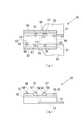
図1は、本実施形態に係るトーリック眼内レンズ2の概略構成を示した図である。図1(a)は平面図、図1(b)は側面図を示す。なお、図1(a)と図1(b)との間では、トーリック眼内レンズ2の向きは対応していない。トーリック眼内レンズ2は、レンズ部と支持部が同じ材質で一体成型されているいわゆるワンピース型で、レンズの材質は軟性のアクリル素材である。トーリック眼内レンズ2は、所定の屈折力を有するレンズ本体2aと、レンズ本体2aに連結された、レンズ本体2aを眼球内で保持するための長尺平板状の2本の支持部2bとを備える。レンズ本体2aおよび支持部2bは可撓性の樹脂材料で形成されている。また、レンズ本体2aおよび支持部2bとは、接合部2eを介して互いに接続されている。 FIG. 1 is a diagram showing a schematic configuration of a toric
図1(b)に示すように、接合部2eは、レンズ外周面から接線状に張り出して形成され、レンズ本体2aの外周と所定範囲にわたって接するように設けられている。また、本実施形態において、レンズ本体2aの外縁付近には、レンズ本体2aの光軸Oを挟んで互いに対向する一対のマーキング2dが施されている。マーキング2dを結ぶ仮想の線が、レンズ本体2aの弱主経線を表し、レンズ本体2aの光軸Oにおいてこの仮想の線に直交する線が、強主経線を表す。したがって、術者は、トーリック眼内レンズ2を患者の眼球内に挿入した後、患者の角膜の強主経線方向とレンズ本体2aのマーキング2dが表す弱主経線方向とが一致するように、トーリック眼内レンズ2の位置を調整することができる。 As shown in FIG. 1B, the
本実施形態において、後述する眼内レンズ挿入器具1内では、2つの支持部2bのうちの一方の支持部2bが、レンズ本体2aの後側、他方の支持部2bがレンズ本体2aの前側に配置されるように、トーリック眼内レンズ2がステージ部12にセットされる。なお、レンズ本体2aの前側に配置される支持部を前方支持部、レンズ本体2aの後側に配置される支持部を後方支持部とする。 In the present embodiment, in the intraocular
本実施形態におけるトーリック眼内レンズ2は、支持部2bにシボ加工が施されている。これにより、プランジャー30によるトーリック眼内レンズ2の押圧移動の際に、トーリック眼内レンズ2の姿勢を安定させることができる。具体的には、例えばプランジャー30によってトーリック眼内レンズ2が押圧移動されるときに、支持部2bとノズル本体10の内壁面との間に適度な摩擦力が生じることでトーリック眼内レンズ2がノズル本体10内で回転しないように防止することができる。また、支持部2bにシボ加工が施されていることで、トーリック眼内レンズ2がノズル本体10内で折り畳まれるときに、支持部2bがレンズ本体2aに張り付かないように防止することもできる。また、本実施形態では、図1(b)に示すように、トーリック眼内レンズ2のレンズ本体2aの周辺部、すなわちレンズ本体2aと支持部2bとの連結部分において、レンズ本体2aが持つ光学面の傾きを緩和するような曲率の小さい光学面2cを設けることでレンズの中心厚を減少させて、レンズの断面積も小さくし、薄型のレンズ形状を実現している。ここで、光学面2cは平坦な形状でもよい。 In the toric
なお、接合部2eがレンズ本体2aの外周と接している範囲では、前面の光学部径は、その他の範囲より加工マージンンの分だけ僅かに大きくなっているため、前面において光学部はわずかに楕円形状(非円形状)になっている。また、後面光学部も、接合部2eがレンズ本体2aの外周と接している範囲では、その他の範囲に比べて10%ほど大きい光学部径になっている、すなわち接合部2eにも光学レンズ面としての機能を持っている部分がある。これによりレンズ本体2aに対して規定される所定の寸法の中で少しでもレンズの有効範囲を広くしている。一般的に、接合部2eに接していない範囲のレンズ本体2aの光学部径は5.5mmから7.0mmである。 In the range where the
図2に、本実施形態のトーリック眼内レンズの眼内への挿入に用いられる眼内レンズ挿入器具1の概略構成を示す。図2(a)はステージ蓋部13を開蓋した場合の眼内レンズ挿入器具1の平面図、図2(b)はステージ蓋部13を閉蓋した場合の眼内レンズ挿入器具1の側面図を示している。眼内レンズ挿入器具1のノズル本体10は、断面が略矩形の筒状部材であり、片側の端部に大きく開口した後端部10bと、別の側の端部に細く絞られた挿入筒部100としてのノズル部15および先端部10aとを備える。図2(b)に示すように、先端部10aは斜めに開口している。プランジャー30は、ノズル本体10に挿入され往復運動可能である。 FIG. 2 shows a schematic configuration of an intraocular
以下の説明において、ノズル本体10の後端部10bから先端部10aへ向かう方向を前方向、その逆方向を後方向、図2(a)において紙面手前側を上方向、その逆方向を下方向、図2(b)において紙面手前方向を左方向、その逆方向を右方向とする。また、この場合、上側は後述するレンズ本体2aの光軸前側に、下側はレンズ本体2aの光軸後側に、前側はプランジャー30による押圧方向前側に、後側はプランジャー30による押圧方向後側に相当する。 In the following description, the direction from the
ノズル本体10の後端部10b付近には、板状に迫り出し、使用者がプランジャー30をノズル本体10の先端側に押し込む際に指を掛けるホールド部11が一体的に設けられている。また、ノズル本体10におけるノズル部15の後側には、トーリック眼内レンズ2をセットするステージ部12が設けられている。このステージ部12は、ステージ蓋部13を開蓋することでノズル本体10の上側に開口するようになっている。また、ステージ部12には、ノズル本体10の下側から位置決め部材50が取り付けられている。この位置決め部材50によって、使用前(輸送中)においてもステージ部12にトーリック眼内レンズ2が安定して位置決めされている。 A
すなわち、眼内レンズ挿入器具1においては、製造時に、ステージ蓋部13が開蓋されて位置決め部材50がステージ部12に取り付けられた状態で、トーリック眼内レンズ2がステージ部12に、光軸前側が上になるようにセットされる。そして、ステージ蓋部13を閉蓋させた後出荷され、販売される。さらに、使用時には、使用者が、トーリック眼内レンズ用の潤滑剤が充填された注射器の針を挿入部20のニードル孔20aからステージ部12内に挿入して潤滑剤を注入する。そして、使用者はステージ蓋部13を閉蓋したままで位置決め部材50を取り外し、その後プランジャー30をノズル本体10の先端側に押し込む。 That is, in the intraocular
これにより、プランジャー30によってトーリック眼内レンズ2を押圧し、ノズル部15まで移動させた上で、先端部10aよりトーリック眼内レンズ2を眼球内に放出する。なお、眼内レンズ挿入器具1におけるノズル本体10、プランジャー30、位置決め部材50はポリプロピレンなどの樹脂の素材で形成される。ポリプロピレンは医療用機器において実績があり、耐薬品性などの信頼性も高い素材である。 As a result, the toric
また、ステージ蓋部13の一部には、薄肉部とすることによって確認窓部17が形成されている。なお、ステージ蓋部13において確認窓部17をどの程度の薄肉部にするかは、ステージ蓋部13を形成する材料と確認窓部17からのトーリック眼内レンズの視認性に基づいて適宜決定すればよい。また、確認窓部17を形成することで、ステージ蓋部13の成形時のヒケを軽減する効果も期待できる。 Further, a
図3にはノズル本体10の平面図を示す。前述のようにノズル本体10においては、トーリック眼内レンズ2はステージ部12にセットされる。そして、その状態でプランジャー30によってトーリック眼内レンズ2が押圧されて先端部10aから放出される。なお、ノズル本体10の内部にはノズル本体10の外形の変化に応じて断面形状が変化する貫通孔10cが設けられている。そして、トーリック眼内レンズ2が放出される際は、トーリック眼内レンズ2は、ノズル本体10内の貫通孔10cの断面形状の変化に応じて変形し、患者の眼球に形成された切開創に入り易い形に変形した上で放出される。 FIG. 3 shows a plan view of the
また、先端部10aは、ノズル部15の上側の領域が下側の領域より前側になるように斜めにカットされた、いわゆるベベルカット形状となっている。なお、本実施形態に係るノズル部15の先端の詳細については後述するが、この先端部10aの斜めにカットされた形状については、左右方向から見て直線的に斜めにカットされていてもよいし、外側に膨らみを持つように、すなわち曲面形状となるように斜めにカットされていてもよい。 Further, the
ステージ部12には、トーリック眼内レンズ2のレンズ本体2aの径より僅かに大きな幅を有するステージ溝12aが形成されている。ステージ溝12aの前後方向の寸法は、トーリック眼内レンズ2の両側に延びる支持部2bを含む最大幅寸法よりも大きく設定されている。また、ステージ溝12aの底面によって、トーリック眼内レンズの載置面であるセット面12bが形成されている。セット面12bの上下方向位置は、ノズル本体10の貫通孔10cの底面の高さ位置よりも上方に設定されており、セット面12bと貫通孔10cの底面とは底部斜面10dによって連結されている。 The
ステージ部12とステージ蓋部13とは一体に形成されている。ステージ蓋部13はステージ部12と同等の前後方向の寸法を有している。ステージ蓋部13は、ステージ部12の側面がステージ蓋部13側に延出して形成された薄板状の連結部14によって連結されている。連結部14は中央部で屈曲可能に形成されており、ステージ蓋部13は、連結部14を屈曲させることでステージ部12に上側から重なり閉蓋することができる。 The
ステージ蓋部13において、閉蓋時にセット面12bと対向する面には、ステージ蓋部13を補強し、トーリック眼内レンズ2の位置を安定させるためのリブ13a、13bと、プランジャー30の上側のガイドとしての案内突起13cが設けられている。また、ステージ蓋部13には、トーリック眼内レンズ2を眼球内に挿入する作業の前にステージ部12にヒアルロン酸を注射器で注入するための挿入孔としてのニードル孔20aが設けられている。ニードル孔20aは、ステージ蓋部13を閉じたときに、ステージ部12の外部とステージ部12に収納されたトーリック眼内レンズ2とを接続する孔である。使用者は、トーリック眼内レンズ2の挿入作業の前にニードル孔20aから注射器の針を挿入し、ステージ部12内の必要な位置に粘弾性物質であるヒアルロン酸を供給する。 In the
ステージ部12のセット面12bの下側には、位置決め部材50が取外し可能に設けられている。図4に、位置決め部材50の概略構成を示す。図4(a)は位置決め部材50の平面図を示し、図4(b)は位置決め部材50の左側面図を示している。位置決め部材50はノズル本体10と別体として構成されており、一対の側壁部51、51が連結部52で連結された構造とされている。それぞれの側壁部51の下端には、外側に向けて延出して広がる保持部53、53が形成されている。 A positioning
そして、側壁部51、51の内側には、上側に突出した一対の第1載置部54、54が形成されている。さらに、第1載置部54、54の上端面における外周側には、第1位置決め部55、55が突出して形成されている。第1位置決め部55、55の内側どうしの離隔長さは、トーリック眼内レンズ2のレンズ本体2aの径寸法よりも僅かに大きく設定されている。 A pair of first mounting
また、側壁部51、51の内側には、上側に突出した一対の第2載置部56、56が形成されている。第2載置部56、56の上面の高さは、第1載置部54、54の上面の高さと同等になっている。さらに、第2載置部56、56の上面において外側の部分には、第2載置部56、56の左右方向の全体にわたって上側にさらに突出する第2位置決め部57、57が形成されている。第2位置決め部57、57の内側どうしの離隔長さは、トーリック眼内レンズ2のレンズ本体2aの径寸法よりも僅かに大きく設定されている。 Further, a pair of second mounting
さらに、側壁部51、51の内側には、トーリック眼内レンズ2の支持部2bのうち前方支持部の一部が載置される第3載置部58が形成されている。さらに、第3載置部58から上側にさらに突出する第3位置決め部59が形成されている。第3位置決め部59には前方支持部の一部が当接する。そして、側壁部51、51の内側には、トーリック眼内レンズ2の支持部2bのうち後方支持部の一部が載置される第4載置部60が形成されている。さらに、第4載置部60から上側にさらに突出する第4位置決め部61が形成されている。第4位置決め部61には後方支持部の一部が当接する。なお、図4(b)に示すように、第4載置部60および第4位置決め部61の上面の高さは、第1〜3載置部および第1〜3位置決め部の上面の高さよりも低くなるように設けられている。一方、側壁部51、51の外側には、位置決め部材50を取り外す際に不必要な回転を防止するための回転防止壁部62が設けられている。 Further, inside the
上記の位置決め部材50は、ノズル本体10のセット面12bの下側から組み付けられる。ノズル本体10のセット面12bには、厚さ方向にセット面12bを貫通するセット面貫通孔12cが形成されている。セット面貫通孔12cの外形は、位置決め部材50の第1〜4載置部および第1〜4位置決め部を上側から見た形状に対し僅かに大きな略相似形状とされている。そして、位置決め部材50がノズル本体10に取り付けられる際には、第1〜4載置部および第1〜4位置決め部が、セット面12bの下側からセット面貫通孔12cに挿入され、セット面12bの上側に突出する。 The positioning
そして、トーリック眼内レンズ2がセット面12bにセットされる際には、レンズ本体2aの外周部底面が、第1載置部54、54及び第2載置部56、56の上面に載置される。また、レンズ本体2aは第1位置決め部55、55及び第2位置決め部57、57によって水平方向(セット面12bに水平な方向)に対して位置規制される。さらに、トーリック眼内レンズ2の2本の支持部2bがそれぞれ第3載置部58、第4載置部60の上面に載置される。また、2本の支持部2bは、それぞれ第3位置決め部59、第4位置決め部61によって水平方向に対して位置規制される。 When the toric
図5にはプランジャー30の概略構成を示す。プランジャー30は、ノズル本体10よりもやや大きな前後方向長さを有している。そして、円柱形状を基本とした先端側の作用部31と、矩形ロッド形状を基本とした後端側の挿通部32とから形成されている。そして、作用部31は、円柱形状とされた円柱部31aと、円柱部31aの左右方向に広がる薄板状の扁平部31bとを含んで構成されている。図5(a)には、プランジャー30の作用部31(円柱部31a)の中心軸CXを示す。ここで、プランジャー30の先端は一般的に0.5mmから2.0mmの幅(太さ)である。これより細い場合はプランジャー強度が弱くなり、レンズを安定して押出すことができない。逆にこれより太い場合は眼内レンズを眼内に挿入するための創口が大きくなり、惹起乱視と呼ばれる乱視が発生し視機能に悪影響を与える可能性がある。 FIG. 5 shows a schematic configuration of the
作用部31の先端部分には、切欠部31cが形成されている。この切欠部31cは、図5(b)から分かるように、作用部31の下方向に開口し左右方向に貫通する溝状に形成されている。また、図5(b)から分かるように、切欠部31cの先端側の溝壁は作用部31の先端側に行くに連れて下方に向かう傾斜面で形成されている。 A
また、左右の扁平部31bの前後方向の中途および基端付近には、スリット31d、31fが形成されている。スリット31d、31fは、扁平部31を左右方向に延伸する切り込みと前後方向に延伸する切り込みとからなる略L字形状となるように形成されている。また、扁平部31bには、スリット31d、31fが形成されることにより可動片31e、31gが形成される。可動片31e、31gは、プランジャー30がノズル本体10内を移動する際に、円柱部31aがノズル本体10の左右方向における中央に位置するよう、いわゆる軸ずれ防止の機能を果たす。本実施形態では、二対の可動片31e、31gが形成されているが、一対のみまたは三対以上形成されていてもよい。 Further, slits 31d and 31f are formed in the middle of the left and right
挿通部32は、全体的に略H字状の断面を有しており、その左右方向及び上下方向の寸法は、ノズル本体10の貫通孔10cよりも僅かに小さく設定されている。また、挿通部32の後端には、上下左右方向に広がる円板状の押圧板部33が形成されている。 The
挿通部32の前後方向の中央より先側の部分には、挿通部32の上側に向けて突出し、プランジャー30の素材の弾性により上下に移動可能な爪部32aが形成されている。そして、プランジャー30がノズル本体10に挿入された際には、ノズル本体10の上面において厚さ方向に設けられた図3に示す係止孔10eと爪部32aが係合し、このことにより初期状態におけるノズル本体10とプランジャー30との相対位置が決定される。なお、爪部32aと係止孔10eの形成位置は、係合状態において、作用部31の先端が、ステージ部12にセットされたトーリック眼内レンズ2のレンズ本体2aの後側に位置し、レンズ本体2aの後側の支持部2bを切欠部31cが下方から支持可能な場所に位置するよう設定されている。また、挿通部32においても、スリット31d、31fと同様に、左右方向に延伸する切り込みと前後方向に延伸する切り込みとからなる略L字形状のスリットが形成されてもよい。このように挿通部32に形成されたスリットも、プランジャー30の軸ずれ防止の機能を果たす。 A
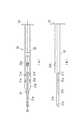
図6(a)〜(d)および図7(a)〜(d)に、本実施形態における試作したトーリック眼内レンズ110〜180を概略的に示す。図6(a)〜(d)および図7(a)〜(d)では、トーリック眼内レンズ110〜180がステージ部12にセットされたときの、プランジャー30の中心軸CXに対応する軸を軸AXとする。すなわち、眼内レンズ挿入器具1において、トーリック眼内レンズ110〜180は、プランジャー30によって軸AX方向に押し出される。また、トーリック眼内レンズ110〜180の光軸方向に垂直な平面(紙面と平行な平面)において軸AXと直交する軸を軸BXとする。また、レンズ本体の光軸中心を通って一対の接合部を結ぶ軸を軸DXとする。また、レンズ本体の外周においてプランジャー30の先端が当接する位置をPとする。さらに、レンズ本体の弱主経線とプランジャー30の押し出し軸(軸AX)とのなす鋭角をθとする。 6 (a) to 6 (d) and 7 (a) to 7 (d) schematically show the prototype toric
本実施形態において、図6(a)〜(d)および図7(a)〜(d)に示すように、トーリック眼内レンズ2のマーキング2dと同様に、トーリック眼内レンズ110〜180のレンズ本体110a〜180aには、弱主経線方向を示すためのマーキング110d〜180dが施されている。なお、マーキング110d〜180dは、レンズ本体110a〜180aにおける弱主経線の両端付近に設けられた一対の印としてレンズ本体110a〜180aに施されている。 In the present embodiment, as shown in FIGS. 6 (a) to 6 (d) and FIGS. 7 (a) to 7 (d), the lenses of the toric
レンズ本体110a〜180aの光軸に垂直な平面におけるレンズ本体110a〜180aの厚さは、弱主経線方向において最大となる。ここで、レンズ本体の厚さとは、レンズ本体の外周における厚さ(エッジ厚)を意味する。そして、レンズ本体の中心を通る他の方向におけるレンズ本体110a〜180aの厚さは、弱主経線方向の厚さに比べて薄くなる。より具体的には、レンズ本体110a〜180aの光軸に垂直な平面において、弱主経線と重なるレンズ本体の中心を通る線を想定し、当該線を時計回りまたは反時計回りに、レンズ本体110a〜180aの一対の接合部110e〜180eを結ぶ仮想の線DXと重なるまで回転させるとする。このとき、回転させる線が示す方向におけるレンズ本体110a〜180aの厚さは、弱主経線方向からの回転角度が大きくなるにつれて薄くなり、一旦極小値を取った後、レンズ本体110a〜180aの中心を通る方向がレンズ本体110a〜180aの一対の接合部110e〜180eを結ぶ仮想の線DXが表す方向に近づくにつれて厚くなる。 The thickness of the
なお、本実施形態において、一対の接合部110e〜180eを結ぶ仮想の線DXは、レンズ本体2aの厚さが極大値を取る方向を示す線として規定され、レンズ本体110a〜180aの中心を通り、接合部110e〜180eの所定の位置を互いに結ぶ線であれば、図6(a)〜(d)および図7(a)〜(d)に示す線に限られない。 In the present embodiment, the virtual line DX connecting the pair of
以上より、例えば図6(a)に示すトーリック眼内レンズ110のレンズ本体110aの厚さは、軸AXと重なるレンズ本体110aの中心を通る線を時計回りに回転させた場合に、軸AX方向において極大値を取り、軸AXと軸DXとの間で極小値を取った後、軸DX方向において極大値を取り、軸DXと軸AXとの間で極小値を取った後、軸AX方向において再び極大値を取る。すなわち、レンズ本体110aの弱主経線と軸DXとの間で、レンズ本体110aの厚さが極大値と極小値を取るように変化する。なお、他のレンズ本体120a〜180aの厚さの変化についても同様に考えられる。 From the above, for example, the thickness of the
次に、本実施形態におけるトーリック眼内レンズ110〜180を眼内レンズ挿入器具1によって押し出す場合の、ノズル本体10内におけるトーリック眼内レンズ110〜180とプランジャー30との位置関係について図8(a)、(b)を参照しながら説明する。なお、図8(a)、(b)においては、ノズル本体10およびプランジャー30を破線で示し、トーリック眼内レンズ110、120を実線で示す。 Next, FIG. 8 shows the positional relationship between the toric
図8(a)には、眼内レンズ挿入器具1によるトーリック眼内レンズ120の眼内への挿入時における、ノズル本体10内でのトーリック眼内レンズ120とプランジャー30との位置関係を例示する。上述の通り、トーリック眼内レンズ120のレンズ本体120aの厚さは、一対のマーキング120dを結ぶ仮想の線(図6(b)では軸BXと一致)が示す方向と軸DXが示す方向とで極大値を取る。すなわち、ノズル本体10において、プランジャー30の先端がレンズ本体120aに当接する位置Pは、レンズ本体120aの厚さが極大値を取る2つの部分に挟まれた部分となる。 FIG. 8A illustrates the positional relationship between the toric
この結果、プランジャー30によるトーリック眼内レンズ120の押し出し時に、プランジャー30の先端の両側におけるレンズ本体120aの厚さがより厚くなってプランジャー30の先端の位置ずれが抑えられる結果、プランジャー30の中心軸CXと押し出し方向(軸AX方向)とが一致した状態を好適に維持することができる。 As a result, when the toric
また、図8(b)には、眼内レンズ挿入器具1によるトーリック眼内レンズ110の眼内への挿入時における、ノズル本体10内でのトーリック眼内レンズ110とプランジャー30との位置関係を例示する。上述の通り、トーリック眼内レンズ110のレンズ本体110aの厚さは、一対のマーキング110dを結ぶ仮想の線(図6(a)では軸AXと一致)が示す方向と軸DXが示す方向とで極大値を取る。すなわち、ノズル本体10において、プランジャー30の先端がレンズ本体120aに当接する位置Pは、レンズ本体120aの厚さが極大値を取る部分となる。 Further, FIG. 8B shows the positional relationship between the toric
この結果、プランジャー30によるトーリック眼内レンズ110の押し出し時に、プランジャー30の先端の両側におけるレンズ本体110aの厚さがより薄くなる結果、プランジャー30の先端が、レンズ本体120aの厚さが極大値を取る部分からいずれかの側にずれやすくなる。この場合、図8(b)に例示するように、プランジャー30の先端がずれた結果、プランジャー30の中心軸CXと押し出し方向(軸AX方向)とが一致しない状態となる。このようにプランジャー30の先端がずれると、プランジャー30によるトーリック眼内レンズ110の押し出し操作が安定せず、術者による施術に支障をきたす可能性がある。 As a result, when the toric
図9には、図6(a)〜(d)および図7(a)〜(d)に示す弱主経線の各パターンの眼内レンズ110〜180について、プランジャー30による押し出し時に、上記のようにプランジャー30の先端がずれるか否かを検証した結果を示す。図中「レンズ」の各数字は、上記のトーリック眼内レンズの符号を意味する。また、図中「軸ずれ」の「なし」は、図8(a)に例示するように、プランジャー30の中心軸CXと押し出し方向(軸AX方向)とが一致した状態でプランジャー30によるトーリック眼内レンズの押し出しを行うことができたことを意味する。図中「軸ずれ」の「あり」は、図8(b)に例示するように、プランジャー30によるトーリック眼内レンズの押し出し時に、プランジャー30の中心軸CXと押し出し方向(軸AX方向)とが一致しない状態になったことを意味する。 In FIG. 9, the
図9に示すようにトーリック眼内レンズ120、130、160、180においては、プランジャー30の軸ずれが生じない。すなわち、プランジャー30によるトーリック眼内レンズ120、130、160、180の押し出し時に、ノズル本体10内でのトーリック眼内レンズ120、130、160、180とプランジャー30との位置関係は、図8(a)に例示するようにプランジャー30の中心軸CXと軸AXとが一致する。ここで、図6(b)、(c)および図7(b)、(d)を参照すると、トーリック眼内レンズのレンズ本体の弱主経線(図中EX)を示す一対のマーキングの一方、すなわち弱主経線の一端が、レンズ本体の外周においてプランジャー30の先端が当接する位置(図中P)に対して、レンズ本体の光軸中心を通って一対の接合部を結ぶ軸(軸DX)とは反対側に位置し、かつ、レンズ本体の弱主経線とプランジャー30の押し出し軸(軸AX)とのなす鋭角(図中θ)が、0°より大きく90°以下である場合に、プランジャー30の軸ずれが生じないといえる。また、レンズ本体の外周における厚さが、レンズ本体の外周においてプランジャーの先端が当接する位置で極小値を取るように構成すると、レンズ本体が周りよりも薄い部分にプランジャー30が当接することで、軸ずれがより好適に抑えられると考えられる。 As shown in FIG. 9, in the toric
また、トーリック眼内レンズは、眼内への挿入直後に、眼内における主経線の位置(方向)を合わせる必要があるが、このような態様のトーリック眼内レンズでは、位置合わせの際にトーリック眼内レンズを回転させる角度が少なくて済み、手術をより容易にすることができる。その理由として、実際の手術においては切開によって角膜乱視を低減することができるため、角膜の強主経線側を切開して、トーリック眼内レンズを挿入する場合が多い。その場合、トーリック眼内レンズを挿入する方向と乱視の強主経線方向は一致している。さらに、トーリック眼内レンズの弱主経線の軸を乱視軸に位置合わせする際にはトーリック眼内レンズを時計回りに回転させることが通例となっている。そのため、本実施形態に示すようにレンズ本体の弱主経線とプランジャー30の押し出し軸(軸AX)とのなす鋭角(図中θ)が、0°より大きく90°以下である場合には、トーリック眼内レンズを乱視患者に挿入した直後において、位置合わせのための回転方向はトーリック眼内レンズを時計回りに回転させる向きであり、その回転角度は鋭角をなす。 Further, the toric intraocular lens needs to align the position (direction) of the main meridian in the eye immediately after being inserted into the eye. However, in such a toric intraocular lens, the toric is used for alignment. The angle at which the intraocular lens is rotated is small, which makes the operation easier. The reason is that in actual surgery, corneal astigmatism can be reduced by incision, so in many cases, a toric intraocular lens is inserted by incising the strong main meridian side of the cornea. In that case, the direction in which the toric intraocular lens is inserted and the direction of the strong main meridian of astigmatism are the same. Further, when aligning the axis of the weak main meridian of the toric intraocular lens with the astigmatic axis, it is customary to rotate the toric intraocular lens clockwise. Therefore, as shown in the present embodiment, when the sharp angle (θ in the figure) formed by the weak main meridian of the lens body and the extrusion axis (axis AX) of the
逆に弱主経線の軸が支持部の接合部にある場合には、位置合わせしたい向きとトーリックマークが示す軸(弱主経線の軸)は鈍角をなすため、鋭角の場合に比べて位置合わせのための回転量は多くなってしまう。なお、押し出し軸と弱主経線の軸を一致させた場合、回転量は理想的に最小になると考えられるが、実際には、粘弾性物質の除去や眼内安定性を整える作業を行う際に理想位置からトーリック眼内レンズが時計回りの方向に必要以上に回動してしまうことが想定される。その場合にはトーリック眼内レンズを理想位置に戻すため、180°近く回転させる必要が生じ、最も回転量が多くなってしまうというリスクが懸念されるので、実際は一致させないほうが好適な態様となる。 On the contrary, when the axis of the weak main meridian is at the joint of the support part, the direction to be aligned and the axis indicated by the toric mark (the axis of the weak main meridian) form an obtuse angle, so the alignment is performed compared to the case of an acute angle. The amount of rotation for this will increase. When the extrusion axis and the axis of the weak main meridian are aligned, the amount of rotation is considered to be ideally the minimum, but in reality, when performing work to remove viscoelastic substances and adjust intraocular stability. It is assumed that the toric intraocular lens rotates more than necessary in the clockwise direction from the ideal position. In that case, in order to return the toric intraocular lens to the ideal position, it is necessary to rotate it by about 180 °, and there is a risk that the amount of rotation will be the largest. Therefore, in practice, it is preferable not to match.
また、図9に示すようにトーリック眼内レンズ110、140、150、170においては、プランジャー30の軸ずれが生じる。すなわち、プランジャー30によるトーリック眼内レンズ110、140、150、170の押し出し時に、ノズル本体10内でのトーリック眼内レンズ110、140、150、170とプランジャー30との位置関係は、図8(b)に例示するようにプランジャー30の中心軸CXが軸AXからずれた状態となる。ここで、図6(a)、(d)および図7(a)、(c)を参照すると、トーリック眼内レンズのレンズ本体の弱主経線(図中EX)を示す一対のマーキングの一方、すなわち弱主経線の一端が、レンズ本体の外周においてプランジャー30の先端が当接する位置(図中P)に対して、レンズ本体の光軸中心を通って一対の接合部を結ぶ軸(軸DX)とは反対側あるいはプランジャー30の押し出し軸(軸AX)と重なる位置に位置し、かつ、レンズ本体の弱主経線と軸AXとのなす鋭角(図中θ)が、90°より大きく180°以下となる場合に、プランジャー30の軸ずれが生じるといえる。 Further, as shown in FIG. 9, in the toric
なお、眼内レンズ挿入器具1を用いてトーリック眼内レンズ110〜180をプランジャー30で押し出す際の押し出し荷重について評価したところ、押し出し荷重は折り畳まれるトーリック眼内レンズ2の断面形状の断面積に相関して大きくなる傾向はあるが、荷重値の差は大きくなかった。例えば円柱屈折力が+6.00Dのトーリック眼内レンズにおいて、押し出し荷重の差は大きくとも1N程度であり、手術に影響するほどの差ではなかった。また、実際に眼内レンズ挿入術の実績が十分ある臨床医を対象にプランジャー30の押し出し感覚の評価を行ったところ、弱主経線の向きによらず同じ感覚で押し出しできるという評価結果が得られた。すなわち、本実施形態において、トーリック眼内レンズ110〜180の弱主経線をプランジャー30の軸ずれが生じないように構成しても、プランジャー30による押し出し荷重が手術に影響するほど大きくなる懸念はないといえる。 When the extrusion load when the toric
以上が本実施形態に関する説明であるが、上記のレンズや挿入部などの構成は、上記の実施形態に限定されるものではなく、本発明の技術的思想と同一性を失わない範囲内において種々の変更が可能である。例えば、より好ましくは、上記の鋭角θは、レンズ本体の外周においてプランジャー30の先端が当接したときに、レンズ本体の弱主経線を延長した線がプランジャー30と交わらない角度以上であり90°以下である。また、本実施形態において、レンズ本体の外周における厚さ(エッジ厚)の変化が光軸周りの角度に対して最も大きくなるのは、弱主経線方向と強主経線方向の中間、すなわちθが45°で最大となることがわかった。この場合、プランジャー30の先端当接するエッジ厚が極小となるだけでなく、この極小値とプランジャー30の両側にあるエッジ厚との差が最大になるため、プランジャー30の先端の位置ずれを効率よく抑えることができる。また、トーリック眼内レンズの製造において弱主経線方向を示すマーキングが、製造誤差により、弱主経線方向に対して±5°ずれて施される可能性がある。これらの点を踏まえると、上記の鋭角は、45°が最良であるが、好ましくは10°以上80°以下であり、さらに好ましくは実質的に45°、すなわち45°±5°となる範囲の角度である。 The above is the description of the present embodiment, but the configuration of the lens, the insertion portion, and the like is not limited to the above embodiment, and can be various as long as the same as the technical idea of the present invention is not lost. Can be changed. For example, more preferably, the acute angle θ is equal to or greater than the angle at which the line extending the weak main meridian of the lens body does not intersect with the
また、別の態様では、一対の接合部を結ぶ軸(DX)と弱主経線とがなす角を45度としてもよい。この場合、一対の接合部に接合するトーリック眼内レンズの断面形状が、トーリック眼内レンズの等価球面度数と同じ屈折力を持つ単焦点眼内レンズの断面形状と似た形状となる。そのため、トーリック眼内レンズの機械的特性を単焦点眼内レンズの機械的特性と同等にすることができる。機械的特性を同等にすることができることは、眼内での安定性が同等であることを意味し、安定した手術結果を得ることができる。 In another aspect, the angle formed by the axis (DX) connecting the pair of joints and the weak main meridian may be 45 degrees. In this case, the cross-sectional shape of the toric intraocular lens joined to the pair of joints is similar to the cross-sectional shape of the single-focus intraocular lens having the same refractive power as the equivalent spherical power of the toric intraocular lens. Therefore, the mechanical characteristics of the toric intraocular lens can be made equivalent to the mechanical characteristics of the single focus intraocular lens. Being able to equalize the mechanical properties means that the stability in the eye is equivalent, and stable surgical results can be obtained.
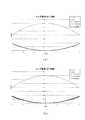
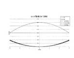
図10(a)、(b)、図11(a)、(b)、図12に、トーリック眼内レンズの光軸を通る断面形状を示す。この図における、35°方向、45°方向、55°方向とは弱主径線方向を0°方向、強主径線方向を90°方向としたときの角度に対応する方向である。図10(a)、(b)、図11(a)、(b)、図12は、眼内主点屈折力が+20.0Dのトーリック眼内レンズの断面形状を例示したものである。図中、横軸は光軸からの距離r(mm)、縦軸はレンズ後面頂点からの距離Z(mm)で、上面が前面(FC)で非球面形状、下面が後面で単焦点レンズの後面BCとトーリック面を示している。トーリック面の断面形状は円柱屈折力の大きい方からToric(Large)、Toric(Middle)、Toric(Small)として示してある。図からわかるように、強主経線方向と弱主経線方向では単焦点眼内レンズとトーリック眼内レンズで形状が異なっているが、45°方向については、機械的特性に影響を及ぼすほどの差はない。軸DXについては接合部2eとレンズ本体2aが接する円弧の中点同士を結ぶ軸、もしくは支持部2bが2eに接続する円弧の中点同士を結ぶ軸が望ましい。 10 (a), (b), 11 (a), (b), and 12 show cross-sectional shapes that pass through the optical axis of the toric intraocular lens. In this figure, the 35 ° direction, the 45 ° direction, and the 55 ° direction are the directions corresponding to the angles when the weak main radial direction is the 0 ° direction and the strong main radial direction is the 90 ° direction. 10 (a), 10 (b), 11 (a), 11 (b), and 12 show the cross-sectional shape of a toric intraocular lens having an intraocular principal point refractive power of + 20.0D. In the figure, the horizontal axis is the distance r (mm) from the optical axis, the vertical axis is the distance Z (mm) from the apex of the rear surface of the lens, the upper surface is the front surface (FC) and has an aspherical shape, and the lower surface is the rear surface of the single focus lens. The rear BC and the toric surface are shown. The cross-sectional shape of the toric surface is shown as Toric (Large), Toric (Middle), and Toric (Small) from the one with the largest cylindrical refractive power. As can be seen from the figure, the shapes of the single focus intraocular lens and the toric intraocular lens are different in the strong main meridian direction and the weak main meridian direction, but in the 45 ° direction, the difference is enough to affect the mechanical characteristics. There is no. As for the shaft DX, it is desirable that the shaft connects the midpoints of the arcs in which the
また、トーリック眼内レンズの接合部は、レンズ本体の外周と所定範囲にわたって接するように設けられており、この所定範囲であれば機械的特性が変わることなく接合することができる。例として、トーリック眼内レンズの接合部とレンズ本体の外周とが45°±10°の範囲で接する場合、35°方向と55°方向の断面形状を比較すると、単焦点眼内レンズとトーリック眼内レンズの断面形状は45°方向と同様に機械的な特性に影響を及ぼすほどの差がないことが確認できる。ここで、接合部に接する光学部の形状を光学的には差が生じるようにしてもよい。また、一対の接合部を結ぶ軸(DX)は所定範囲内で任意に設定してもよい。 Further, the joint portion of the toric intraocular lens is provided so as to be in contact with the outer circumference of the lens body over a predetermined range, and within this predetermined range, the joint can be joined without changing the mechanical characteristics. As an example, when the junction of the toric intraocular lens and the outer circumference of the lens body are in contact within a range of 45 ° ± 10 °, comparing the cross-sectional shapes in the 35 ° and 55 ° directions, the single focus intraocular lens and the toric eye It can be confirmed that there is no difference in the cross-sectional shape of the inner lens so as to affect the mechanical characteristics as in the 45 ° direction. Here, the shape of the optical portion in contact with the joint portion may be optically different. Further, the axis (DX) connecting the pair of joints may be arbitrarily set within a predetermined range.
ここで、眼内レンズ挿入器具におけるトーリック眼内レンズのレンズ本体の折り畳みの向きについて、特許5603326号では、トーリック眼内レンズの上記でいう45°方向(弱主径線から45°方向)のエッジ厚を単焦点眼内レンズの45°方向のエッジ厚と一致させ、45°方向(弱主径線から45°方向)で折り畳み操作を行うことで、トーリック眼内レンズのベースとなっている単焦点眼内レンズと同じように折り畳み操作が可能となる旨が開示されていると思われる。一方で、本実施形態においては、上述したように、押し出し荷重が、折り畳まれるレンズ本体の断面の断面積に多少なりとも相関することから、相対的に断面積が小さい方向、つまり強主経線を折り畳む(弱主経線を中心に折り畳む)方がより小さい押し出し荷重で押出しすることで、レンズ及び挿入部の破損リスクを小さくすることができるとともに、本実施形態のように押し出し操作の際にプランジャーの軸ずれが生じないようにすることができるため、より安全に安定した押し出しを提供することができる。 Here, regarding the folding direction of the lens body of the toric intraocular lens in the intraocular lens insertion device, in Patent No. 56033326, the edge of the toric intraocular lens in the above-mentioned 45 ° direction (45 ° direction from the weak main diameter line). By matching the thickness with the edge thickness in the 45 ° direction of the single focus intraocular lens and performing the folding operation in the 45 ° direction (45 ° direction from the weak main diameter line), the single focus intraocular lens is the base of the single focus intraocular lens. It seems that it is disclosed that the folding operation is possible in the same manner as the focal intraocular lens. On the other hand, in the present embodiment, as described above, since the extrusion load correlates with the cross-sectional area of the cross section of the lens body to be folded to some extent, the direction in which the cross-sectional area is relatively small, that is, the strong main meridian By extruding with a smaller extrusion load when folded (folding around the weak main meridian), the risk of damage to the lens and the insertion portion can be reduced, and the plunger during the extrusion operation as in the present embodiment can be reduced. Since it is possible to prevent the axial deviation of the above, it is possible to provide a safer and more stable extrusion.
さらに、トーリック眼内レンズの接合部が、レンズ本体の外周と所定範囲にわたって接するように設けられていれば、機械的特性を好適に維持しつつ、接合部とレンズ本体の外周とが互いに接する範囲内で弱主経線の位置を調整することができる。 Further, if the joint portion of the toric intraocular lens is provided so as to be in contact with the outer circumference of the lens body over a predetermined range, the range in which the joint portion and the outer circumference of the lens body are in contact with each other while appropriately maintaining the mechanical characteristics. The position of the weak main meridian can be adjusted within.
上記の実施形態の変形例として、レンズ本体における45°方向のエッジ部分は支持部の接合部と重なる部分である点を踏まえ、トーリック眼内レンズの弱主径線から45°方向のエッジ厚を単焦点眼内レンズのエッジ厚と一致させない構成とすることもできる。また、国際公開第2015/136997号に開示されているように、レンズ本体の光軸回りのエッジの変化を正弦的ではないように変化させ、弱主径線から45°方向のエッジ厚をトーリック眼内レンズのベース形状である単焦点眼内レンズのエッジ厚と異なるようにすることで、光学的な特徴を付加したり、ハンドリング性を向上させたりしてもよい。なお、レンズ本体のエッジには、レンズ本体の形状自体の端面である機械的なエッジと、光学部と非光学部の境界、すなわちレンズとして実効的に機能する部分の外縁に相当する光学的なエッジとが考えられるが、本実施形態におけるレンズ本体のエッジとは光学的なエッジを想定している。 As a modification of the above embodiment, considering that the edge portion in the 45 ° direction of the lens body overlaps with the joint portion of the support portion, the edge thickness in the 45 ° direction from the weak main diameter line of the toric intraocular lens is set. The configuration may not match the edge thickness of the single focus intraocular lens. Further, as disclosed in International Publication No. 2015/136997, the change of the edge around the optical axis of the lens body is changed so as not to be sinusoidal, and the edge thickness in the 45 ° direction from the weak main diameter line is toric. By making the edge thickness different from that of the single-focus intraocular lens, which is the base shape of the intraocular lens, optical features may be added or handleability may be improved. The edge of the lens body is an optical edge corresponding to the mechanical edge which is the end face of the shape of the lens body itself and the boundary between the optical part and the non-optical part, that is, the outer edge of the part which effectively functions as a lens. Although it is considered to be an edge, the edge of the lens body in the present embodiment is assumed to be an optical edge.
さらに、上記の実施形態の変形例として、眼内レンズが眼内でφ9〜11mmに圧縮された状態において、一対の支持部のそれぞれの先端を結んだ線上に弱主径線があるようにしてもよい。一般的に眼内レンズは瞳孔より網膜側に固定されるため、眼内に挿入された状態においては、瞳孔径の大きさより小さい領域しか術者は観察することができない。そのため、術者が支持部先端の位置を把握することは難しい。一方で、本実施形態においては、瞳孔径より小さい領域に弱主径線を示す一対のマークがあり、その延長上に支持部先端があることから、術者は支持部先端の位置を明確に把握することができる。 Further, as a modification of the above embodiment, in a state where the intraocular lens is compressed to φ9 to 11 mm in the eye, a weak main diameter line is formed on the line connecting the tips of the pair of support portions. May be good. Since the intraocular lens is generally fixed to the retina side of the pupil, the operator can observe only a region smaller than the size of the pupil diameter when it is inserted into the eye. Therefore, it is difficult for the operator to grasp the position of the tip of the support portion. On the other hand, in the present embodiment, since there is a pair of marks indicating a weak main diameter line in a region smaller than the pupil diameter and the tip of the support portion is on the extension thereof, the operator can clearly position the tip of the support portion. Can be grasped.
例えば、眼内レンズを挿入した際に後嚢に皺が生じる事例があった場合、従来のレンズでは術者は支持部付け根の位置から支持部先端の位置を推測することしかできず、支持部が存在する範囲を特定することができないため原因究明が困難であった。しかし、本実施形態の場合、術者は支持部が存在する範囲を明確に把握することができるため、眼内レンズの姿勢と皺との関係を調査することができる。また、眼内レンズを固定する水晶体嚢の一部に亀裂が入ってしまった場合、術者は支持部の先端がその亀裂の方向に位置しないように調整することも容易にできる。また、ワンピース型レンズの場合、眼内で回転させる際には支持部先端が水晶体嚢と接することから1対の支持部先端を結ぶ軸とマークの軸が一致していることは眼内におけるレンズ挙動の安定性を高められると考えられる。 For example, if there is a case where wrinkles occur in the posterior capsule when an intraocular lens is inserted, the operator can only infer the position of the tip of the support from the position of the base of the support with the conventional lens, and the support It was difficult to investigate the cause because it was not possible to specify the range in which the lens exists. However, in the case of the present embodiment, since the operator can clearly grasp the range where the support portion exists, the relationship between the posture of the intraocular lens and the wrinkles can be investigated. In addition, if a part of the capsular bag that fixes the intraocular lens is cracked, the operator can easily adjust the tip of the support portion so that it is not located in the direction of the crack. Also, in the case of a one-piece lens, the tip of the support part comes into contact with the capsular bag when it is rotated in the eye, so the axis connecting the tip of the pair of support parts and the axis of the mark are the same as the lens in the eye. It is thought that the stability of behavior can be improved.
さらに、このような眼内レンズを製造する場合、先に製造された同一サイズの眼内レンズを、内径がφ9〜11mmとなっているホルダ等に載置することにより、眼内レンズが眼内で圧縮された状態における支持部とマークの位置関係がわかるので、その情報を基にして製造することができる。なお、眼内での圧縮による支持部の変形がそれほど大きくない場合は、図7(d)に示すように、眼内レンズの初期形状(圧縮されていない状態)において、一対の支持部先端を結ぶ線上に弱主径線があるように製造してもよい。 Further, when manufacturing such an intraocular lens, the intraocular lens is placed in the eye by placing the previously manufactured intraocular lens of the same size on a holder or the like having an inner diameter of φ9 to 11 mm. Since the positional relationship between the support portion and the mark in the compressed state can be known, the manufacturing can be performed based on that information. If the deformation of the support portion due to compression in the eye is not so large, as shown in FIG. 7D, in the initial shape of the intraocular lens (in the uncompressed state), a pair of support portion tips are used. It may be manufactured so that there is a weak main diameter wire on the connecting wire.
1 眼内レンズ挿入器具
2、110、120、130、140、150、160、170、180 トーリック眼内レンズ
2a、110a、120a、130a、140a、150a、160a、170a、180a レンズ本体
2b、110b、120b、130b、140b、150b、160b、170b、180b 支持部
2d、110d、120d、130d、140d、150d、160d、170d、180d マーキング
2e、110e、120e、130e、140e、150e、160e、170e、180e 接合部
10 ノズル本体
100 挿入筒部1 Intraocular
Claims (8)
Translated fromJapanese前記トーリック眼内レンズは、前記トーリック眼内レンズを前記眼内に挿入する挿入筒部を先端に有する略筒状の器具本体と前記トーリック眼内レンズを前記挿入筒部の先端に移動させるプランジャーとを有する眼内レンズ挿入器具に収納され、
前記各接合部は、前記レンズ本体の光軸中心を挟んで互いに向き合う位置に設けられ、
前記レンズ本体の前記弱主経線の一端が、前記レンズ本体の外周において前記プランジャーの先端が当接する位置に対して、前記レンズ本体の光軸中心を通って前記各接合部を結ぶ軸とは反対側に位置し、
前記レンズ本体の前記弱主経線と前記プランジャーの前記トーリック眼内レンズの押し出し軸とのなす角度θが、0°より大きく90°以下であり、
前記角度θが、前記プランジャーの先端が前記レンズ本体の外周に当接したときに、前記弱主経線を延長した線が前記プランジャーと交わらない角度以上であり90°以下である、
ことを特徴とするトーリック眼内レンズ。A toric intraocular lens having a lens body having a weak main meridian and a strong main meridian, a pair of support portions for positioning the lens body in the eye, and a joint portion for joining the lens body and the support portion. It ’s a lens,
The toric intraocular lens is a substantially tubular instrument body having an insertion tube portion at the tip for inserting the toric intraocular lens into the eye, and a plunger for moving the toric intraocular lens to the tip of the insertion tube portion. Stored in an intraocular lens insertion device with
The joints are provided at positions facing each other with the center of the optical axis of the lens body interposed therebetween.
What is the axis connecting the joints through the center of the optical axis of the lens body with respect to the position where one end of the weak main meridian of the lens body comes into contact with the tip of the plunger on the outer circumference of the lens body? Located on the other side,
The lensangle between the extrusion axis of the toric intraocular lens of the weak principal meridian and the plunger of the bodyθ isstate, and are less than 90 ° greater than 0°,
When the tip of the plunger abuts on the outer circumference of the lens body, the angle θ is equal to or greater than an angle at which the extension of the weak main meridian does not intersect with the plunger and is 90 ° or less.
A toric intraocular lens characterized by this.
前記トーリック眼内レンズは、前記トーリック眼内レンズを前記眼内に挿入する挿入筒部を先端に有する略筒状の器具本体と前記トーリック眼内レンズを前記挿入筒部の先端に移動させるプランジャーとを有する眼内レンズ挿入器具に収納され、 The toric intraocular lens is a substantially tubular instrument body having an insertion tube portion at the tip for inserting the toric intraocular lens into the eye, and a plunger for moving the toric intraocular lens to the tip of the insertion tube portion. Stored in an intraocular lens insertion device with
前記各接合部は、前記レンズ本体の光軸中心を挟んで互いに向き合う位置に設けられ、 The joints are provided at positions facing each other with the center of the optical axis of the lens body interposed therebetween.
前記レンズ本体の前記弱主経線の一端が、前記レンズ本体の外周において前記プランジャーの先端が当接する位置に対して、前記レンズ本体の光軸中心を通って前記各接合部を結ぶ軸とは反対側に位置し、 What is the axis connecting the joints through the center of the optical axis of the lens body with respect to the position where one end of the weak main meridian of the lens body comes into contact with the tip of the plunger on the outer circumference of the lens body? Located on the other side,
前記レンズ本体の前記弱主経線と前記プランジャーの前記トーリック眼内レンズの押し出し軸とのなす角度θが、10°より大きく80°より小さい、 The angle θ formed by the weak main meridian of the lens body and the extrusion axis of the toric intraocular lens of the plunger is greater than 10 ° and less than 80 °.
ことを特徴とするトーリック眼内レンズ。A toric intraocular lens characterized by this.
前記トーリック眼内レンズは、前記トーリック眼内レンズを前記眼内に挿入する挿入筒部を先端に有する略筒状の器具本体と前記トーリック眼内レンズを前記挿入筒部の先端に移動させるプランジャーとを有する眼内レンズ挿入器具に収納され、 The toric intraocular lens is a substantially tubular instrument body having an insertion tube portion at the tip for inserting the toric intraocular lens into the eye, and a plunger for moving the toric intraocular lens to the tip of the insertion tube portion. Stored in an intraocular lens insertion device with
前記各接合部は、前記レンズ本体の光軸中心を挟んで互いに向き合う位置に設けられ、 The joints are provided at positions facing each other with the center of the optical axis of the lens body interposed therebetween.
前記レンズ本体の前記弱主経線の一端が、前記レンズ本体の外周において前記プランジャーの先端が当接する位置に対して、前記レンズ本体の光軸中心を通って前記各接合部を結ぶ軸とは反対側に位置し、 What is the axis connecting the joints through the center of the optical axis of the lens body with respect to the position where one end of the weak main meridian of the lens body comes into contact with the tip of the plunger on the outer circumference of the lens body? Located on the other side,
前記レンズ本体の前記弱主経線と前記プランジャーの前記トーリック眼内レンズの押し出し軸とのなす角度θが、0°より大きく90°以下であり、 The angle θ formed by the weak main meridian of the lens body and the extrusion axis of the toric intraocular lens of the plunger is greater than 0 ° and 90 ° or less.
前記各接合部を結ぶ軸と弱主経線のなす鋭角が45°±10°である、 The acute angle between the axis connecting the joints and the weak main meridian is 45 ° ± 10 °.
ことを特徴とするトーリック眼内レンズ。A toric intraocular lens characterized by this.
Applications Claiming Priority (3)
| Application Number | Priority Date | Filing Date | Title |
|---|---|---|---|
| JP2016078333 | 2016-04-08 | ||
| JP2016078333 | 2016-04-08 | ||
| PCT/JP2017/014485WO2017175853A1 (en) | 2016-04-08 | 2017-04-07 | Toric intraocular lens and intraocular-lens insertion instrument |
Publications (2)
| Publication Number | Publication Date |
|---|---|
| JPWO2017175853A1 JPWO2017175853A1 (en) | 2019-02-14 |
| JP6958865B2true JP6958865B2 (en) | 2021-11-02 |
Family
ID=60001136
Family Applications (1)
| Application Number | Title | Priority Date | Filing Date |
|---|---|---|---|
| JP2018510672AActiveJP6958865B2 (en) | 2016-04-08 | 2017-04-07 | Toric intraocular lens and intraocular lens insertion device |
Country Status (10)
| Country | Link |
|---|---|
| US (1) | US10856969B2 (en) |
| EP (1) | EP3441044B1 (en) |
| JP (1) | JP6958865B2 (en) |
| KR (1) | KR102302430B1 (en) |
| CN (1) | CN108882977B (en) |
| ES (1) | ES2972542T3 (en) |
| HU (1) | HUE065671T2 (en) |
| SG (1) | SG11201808839UA (en) |
| TW (1) | TW201740888A (en) |
| WO (1) | WO2017175853A1 (en) |
Families Citing this family (6)
| Publication number | Priority date | Publication date | Assignee | Title |
|---|---|---|---|---|
| US10856969B2 (en)* | 2016-04-08 | 2020-12-08 | Kowa Company, Ltd. | Toric intraocular lens and intraocular lens insertion apparatus |
| ES3015537T3 (en)* | 2016-06-15 | 2025-05-06 | Kowa Co | Toric intraocular lens |
| EP3915518A4 (en)* | 2019-01-25 | 2022-10-26 | Eyebright Medical Technology (Beijing) Co., Ltd. | INTRAOCULAR LENS IMPLANT DEVICE AND PRE-LOADED INTRAOCULAR LENS IMPLANT DEVICE |
| CA3152304A1 (en)* | 2019-10-04 | 2021-04-08 | Andrew R. WALZ | Accommodating intraocular lenses with toric surface |
| US20230404400A1 (en)* | 2020-10-27 | 2023-12-21 | Topcon Corporation | Ophthalmic observation apparatus, method for controlling the same, and recording medium |
| US11357620B1 (en) | 2021-09-10 | 2022-06-14 | California LASIK & Eye, Inc. | Exchangeable optics and therapeutics |
Family Cites Families (28)
| Publication number | Priority date | Publication date | Assignee | Title |
|---|---|---|---|---|
| JPS563326B2 (en) | 1972-09-11 | 1981-01-24 | ||
| US5092880A (en)* | 1988-10-21 | 1992-03-03 | Genjiro Ohmi | Method of determining the astigmatic power and the power for an intraocular lens, for a toric intraocular lens |
| WO1996039106A1 (en)* | 1995-06-06 | 1996-12-12 | Scientific Optics, Inc. | Asymmetric bifocal intraocular lens |
| DE102005028933A1 (en)* | 2005-06-22 | 2006-12-28 | Acri.Tec Gesellschaft für ophthalmologische Produkte mbH | Astigmatic intraocular lens e.g. for correcting astigmatic ametropia, has toroidal refractive front face and toroidal refractive rear face with intraocular lens also has toroidal refractive lens surface |
| US20100079723A1 (en)* | 2008-10-01 | 2010-04-01 | Kingston Amanda C | Toric Ophthalimc Lenses Having Selected Spherical Aberration Characteristics |
| US20100315589A1 (en)* | 2009-06-16 | 2010-12-16 | Valdemar Portney | Toric ophthalmic lens |
| US8357196B2 (en)* | 2009-11-18 | 2013-01-22 | Abbott Medical Optics Inc. | Mark for intraocular lenses |
| EP2343029B1 (en) | 2010-01-09 | 2015-05-06 | Nidek Co., Ltd. | Intraocular lens injection instrument |
| US8256896B2 (en)* | 2010-02-25 | 2012-09-04 | Abbott Medical Optic Inc. | Toric optic for ophthalmic use |
| JP5771907B2 (en)* | 2010-05-31 | 2015-09-02 | 株式会社ニデック | Intraocular lens and intraocular lens insertion device |
| US10394051B2 (en)* | 2010-12-23 | 2019-08-27 | Brien Holden Vision Institute | Toric ophthalmic lens having extended depth of focus |
| US9364316B1 (en)* | 2012-01-24 | 2016-06-14 | Clarvista Medical, Inc. | Modular intraocular lens designs, tools and methods |
| JP6061601B2 (en)* | 2012-10-03 | 2017-01-18 | 興和株式会社 | Intraocular lens |
| WO2014070332A1 (en)* | 2012-10-31 | 2014-05-08 | Novartis Ag | Method and system for providing a toric intraocular lens |
| US9782254B2 (en)* | 2013-02-21 | 2017-10-10 | Singapore Health Services Pte Ltd | Device for single handled injection of an intraocular lens |
| DE102013216020A1 (en)* | 2013-08-13 | 2015-02-19 | Carl Zeiss Meditec Ag | Eye lens with a toric refractive surface profile and a stepped surface structure in the radial direction |
| NL2011433C2 (en) | 2013-09-12 | 2015-03-16 | Oculentis Holding B V | Intraocular lens having partly overlapping additional optical active sectors on opposite sides. |
| EP2873391A1 (en)* | 2013-11-15 | 2015-05-20 | Atttinger Technik AG | Intraocular lens injector, method for folding an intraocular lens and intraocular lens injector system |
| PL3118671T3 (en) | 2014-03-11 | 2022-07-18 | Kowa Company Ltd. | Ophthalmic lens and method for designing ophthalmic lens |
| US20170304047A1 (en)* | 2014-09-02 | 2017-10-26 | Jagrat Natavar DAVE | Intraocular lens customized for astigmatism or combined astigmatism and presbyopia |
| EP4523656A3 (en)* | 2015-01-30 | 2025-05-21 | Alcon Inc. | Modular intraocular lens designs, tools and methods |
| US11141263B2 (en)* | 2015-11-18 | 2021-10-12 | Shifamed Holdings, Llc | Multi-piece accommodating intraocular lens |
| US10856969B2 (en)* | 2016-04-08 | 2020-12-08 | Kowa Company, Ltd. | Toric intraocular lens and intraocular lens insertion apparatus |
| ES3015537T3 (en)* | 2016-06-15 | 2025-05-06 | Kowa Co | Toric intraocular lens |
| JP6826843B2 (en)* | 2016-08-31 | 2021-02-10 | Hoya株式会社 | Intraocular lens, its design method, and its manufacturing method |
| US20180200105A1 (en)* | 2017-01-14 | 2018-07-19 | Rxsight, Inc. | Intraocular lens inserter cartridge with a trailing haptic protection structure |
| US10426602B2 (en)* | 2017-10-05 | 2019-10-01 | Ast Products, Inc. | Intraocular lens (IOL) injector and method of use thereof |
| US20190374334A1 (en)* | 2018-06-07 | 2019-12-12 | Lensgen, Inc. | Intraocular lens device and related methods |
- 2017
- 2017-04-07USUS16/092,188patent/US10856969B2/enactiveActive
- 2017-04-07JPJP2018510672Apatent/JP6958865B2/enactiveActive
- 2017-04-07HUHUE17779231Apatent/HUE065671T2/enunknown
- 2017-04-07TWTW106111741Apatent/TW201740888A/enunknown
- 2017-04-07KRKR1020187029513Apatent/KR102302430B1/enactiveActive
- 2017-04-07WOPCT/JP2017/014485patent/WO2017175853A1/ennot_activeCeased
- 2017-04-07ESES17779231Tpatent/ES2972542T3/enactiveActive
- 2017-04-07SGSG11201808839UApatent/SG11201808839UA/enunknown
- 2017-04-07EPEP17779231.4Apatent/EP3441044B1/enactiveActive
- 2017-04-07CNCN201780022547.3Apatent/CN108882977B/enactiveActive
Also Published As
| Publication number | Publication date |
|---|---|
| US10856969B2 (en) | 2020-12-08 |
| KR102302430B1 (en) | 2021-09-15 |
| US20190091008A1 (en) | 2019-03-28 |
| ES2972542T3 (en) | 2024-06-13 |
| SG11201808839UA (en) | 2018-11-29 |
| CN108882977A (en) | 2018-11-23 |
| EP3441044A4 (en) | 2019-11-20 |
| KR20180133419A (en) | 2018-12-14 |
| TW201740888A (en) | 2017-12-01 |
| CN108882977B (en) | 2021-05-25 |
| EP3441044C0 (en) | 2024-01-24 |
| EP3441044A1 (en) | 2019-02-13 |
| HUE065671T2 (en) | 2024-06-28 |
| JPWO2017175853A1 (en) | 2019-02-14 |
| EP3441044B1 (en) | 2024-01-24 |
| WO2017175853A1 (en) | 2017-10-12 |
Similar Documents
| Publication | Publication Date | Title |
|---|---|---|
| JP6958865B2 (en) | Toric intraocular lens and intraocular lens insertion device | |
| JP6781223B2 (en) | Intraocular lens injector | |
| RU2666117C2 (en) | Bi-radial patient interface | |
| JP4707016B2 (en) | Intraocular lens insertion device and cartridge thereof | |
| WO2015012312A1 (en) | Intraocular lens-inserting instrument | |
| WO2018221434A1 (en) | Lens accommodating container | |
| WO2017217443A1 (en) | Toric intraocular lens, intraocular lens insertion tool, and method for producing toric intraocular lens | |
| JP6669346B2 (en) | Intraocular lens insertion device | |
| HK1262342A1 (en) | Toric intraocular lens and intraocular-lens insertion instrument | |
| JP6841474B2 (en) | Intraocular lens and intraocular lens insertion device | |
| HK1262342B (en) | Toric intraocular lens and intraocular-lens insertion instrument | |
| WO2019054353A1 (en) | Intraocular lens insertion instrument | |
| JP2017080329A (en) | Intraocular lends insertion instrument | |
| JP7066320B2 (en) | Intraocular lens insertion device | |
| WO2017213231A1 (en) | Intraocular lens push-out auxiliary tool | |
| HK1224543B (en) | Intraocular lens-inserting instrument | |
| HK1224543A1 (en) | Intraocular lens-inserting instrument |
Legal Events
| Date | Code | Title | Description |
|---|---|---|---|
| A621 | Written request for application examination | Free format text:JAPANESE INTERMEDIATE CODE: A621 Effective date:20200207 | |
| A131 | Notification of reasons for refusal | Free format text:JAPANESE INTERMEDIATE CODE: A131 Effective date:20210323 | |
| A521 | Request for written amendment filed | Free format text:JAPANESE INTERMEDIATE CODE: A523 Effective date:20210521 | |
| TRDD | Decision of grant or rejection written | ||
| A01 | Written decision to grant a patent or to grant a registration (utility model) | Free format text:JAPANESE INTERMEDIATE CODE: A01 Effective date:20210907 | |
| A61 | First payment of annual fees (during grant procedure) | Free format text:JAPANESE INTERMEDIATE CODE: A61 Effective date:20210929 | |
| R150 | Certificate of patent or registration of utility model | Ref document number:6958865 Country of ref document:JP Free format text:JAPANESE INTERMEDIATE CODE: R150 | |
| R250 | Receipt of annual fees | Free format text:JAPANESE INTERMEDIATE CODE: R250 | |
| R250 | Receipt of annual fees | Free format text:JAPANESE INTERMEDIATE CODE: R250 |