JP6957205B2 - Cartridge and image forming equipment - Google Patents
Cartridge and image forming equipmentDownload PDFInfo
- Publication number
- JP6957205B2 JP6957205B2JP2017107458AJP2017107458AJP6957205B2JP 6957205 B2JP6957205 B2JP 6957205B2JP 2017107458 AJP2017107458 AJP 2017107458AJP 2017107458 AJP2017107458 AJP 2017107458AJP 6957205 B2JP6957205 B2JP 6957205B2
- Authority
- JP
- Japan
- Prior art keywords
- cartridge
- toner
- cartridge according
- discharge port
- sealing portion
- Prior art date
- Legal status (The legal status is an assumption and is not a legal conclusion. Google has not performed a legal analysis and makes no representation as to the accuracy of the status listed.)
- Active
Links
Images


Classifications
- G—PHYSICS
- G03—PHOTOGRAPHY; CINEMATOGRAPHY; ANALOGOUS TECHNIQUES USING WAVES OTHER THAN OPTICAL WAVES; ELECTROGRAPHY; HOLOGRAPHY
- G03G—ELECTROGRAPHY; ELECTROPHOTOGRAPHY; MAGNETOGRAPHY
- G03G21/00—Arrangements not provided for by groups G03G13/00 - G03G19/00, e.g. cleaning, elimination of residual charge
- G03G21/10—Collecting or recycling waste developer
- G03G21/105—Arrangements for conveying toner waste
- G—PHYSICS
- G03—PHOTOGRAPHY; CINEMATOGRAPHY; ANALOGOUS TECHNIQUES USING WAVES OTHER THAN OPTICAL WAVES; ELECTROGRAPHY; HOLOGRAPHY
- G03G—ELECTROGRAPHY; ELECTROPHOTOGRAPHY; MAGNETOGRAPHY
- G03G21/00—Arrangements not provided for by groups G03G13/00 - G03G19/00, e.g. cleaning, elimination of residual charge
- G03G21/16—Mechanical means for facilitating the maintenance of the apparatus, e.g. modular arrangements
- G03G21/18—Mechanical means for facilitating the maintenance of the apparatus, e.g. modular arrangements using a processing cartridge, whereby the process cartridge comprises at least two image processing means in a single unit
- G03G21/1839—Means for handling the process cartridge in the apparatus body
- G03G21/1842—Means for handling the process cartridge in the apparatus body for guiding and mounting the process cartridge, positioning, alignment, locks
- G03G21/1853—Means for handling the process cartridge in the apparatus body for guiding and mounting the process cartridge, positioning, alignment, locks the process cartridge being mounted perpendicular to the axis of the photosensitive member
- G—PHYSICS
- G03—PHOTOGRAPHY; CINEMATOGRAPHY; ANALOGOUS TECHNIQUES USING WAVES OTHER THAN OPTICAL WAVES; ELECTROGRAPHY; HOLOGRAPHY
- G03G—ELECTROGRAPHY; ELECTROPHOTOGRAPHY; MAGNETOGRAPHY
- G03G15/00—Apparatus for electrographic processes using a charge pattern
- G03G15/06—Apparatus for electrographic processes using a charge pattern for developing
- G03G15/08—Apparatus for electrographic processes using a charge pattern for developing using a solid developer, e.g. powder developer
- G03G15/0822—Arrangements for preparing, mixing, supplying or dispensing developer
- G03G15/0844—Arrangements for purging used developer from the developing unit
- G—PHYSICS
- G03—PHOTOGRAPHY; CINEMATOGRAPHY; ANALOGOUS TECHNIQUES USING WAVES OTHER THAN OPTICAL WAVES; ELECTROGRAPHY; HOLOGRAPHY
- G03G—ELECTROGRAPHY; ELECTROPHOTOGRAPHY; MAGNETOGRAPHY
- G03G15/00—Apparatus for electrographic processes using a charge pattern
- G03G15/06—Apparatus for electrographic processes using a charge pattern for developing
- G03G15/08—Apparatus for electrographic processes using a charge pattern for developing using a solid developer, e.g. powder developer
- G03G15/0822—Arrangements for preparing, mixing, supplying or dispensing developer
- G03G15/0865—Arrangements for supplying new developer
- G—PHYSICS
- G03—PHOTOGRAPHY; CINEMATOGRAPHY; ANALOGOUS TECHNIQUES USING WAVES OTHER THAN OPTICAL WAVES; ELECTROGRAPHY; HOLOGRAPHY
- G03G—ELECTROGRAPHY; ELECTROPHOTOGRAPHY; MAGNETOGRAPHY
- G03G15/00—Apparatus for electrographic processes using a charge pattern
- G03G15/06—Apparatus for electrographic processes using a charge pattern for developing
- G03G15/08—Apparatus for electrographic processes using a charge pattern for developing using a solid developer, e.g. powder developer
- G03G15/0822—Arrangements for preparing, mixing, supplying or dispensing developer
- G03G15/0877—Arrangements for metering and dispensing developer from a developer cartridge into the development unit
- G03G15/0881—Sealing of developer cartridges
- G03G15/0886—Sealing of developer cartridges by mechanical means, e.g. shutter, plug
- G—PHYSICS
- G03—PHOTOGRAPHY; CINEMATOGRAPHY; ANALOGOUS TECHNIQUES USING WAVES OTHER THAN OPTICAL WAVES; ELECTROGRAPHY; HOLOGRAPHY
- G03G—ELECTROGRAPHY; ELECTROPHOTOGRAPHY; MAGNETOGRAPHY
- G03G15/00—Apparatus for electrographic processes using a charge pattern
- G03G15/06—Apparatus for electrographic processes using a charge pattern for developing
- G03G15/08—Apparatus for electrographic processes using a charge pattern for developing using a solid developer, e.g. powder developer
- G03G15/0896—Arrangements or disposition of the complete developer unit or parts thereof not provided for by groups G03G15/08 - G03G15/0894
- G03G15/0898—Arrangements or disposition of the complete developer unit or parts thereof not provided for by groups G03G15/08 - G03G15/0894 for preventing toner scattering during operation, e.g. seals
- G—PHYSICS
- G03—PHOTOGRAPHY; CINEMATOGRAPHY; ANALOGOUS TECHNIQUES USING WAVES OTHER THAN OPTICAL WAVES; ELECTROGRAPHY; HOLOGRAPHY
- G03G—ELECTROGRAPHY; ELECTROPHOTOGRAPHY; MAGNETOGRAPHY
- G03G21/00—Arrangements not provided for by groups G03G13/00 - G03G19/00, e.g. cleaning, elimination of residual charge
- G03G21/0005—Arrangements not provided for by groups G03G13/00 - G03G19/00, e.g. cleaning, elimination of residual charge for removing solid developer or debris from the electrographic recording medium
- G03G21/0011—Arrangements not provided for by groups G03G13/00 - G03G19/00, e.g. cleaning, elimination of residual charge for removing solid developer or debris from the electrographic recording medium using a blade; Details of cleaning blades, e.g. blade shape, layer forming
- G—PHYSICS
- G03—PHOTOGRAPHY; CINEMATOGRAPHY; ANALOGOUS TECHNIQUES USING WAVES OTHER THAN OPTICAL WAVES; ELECTROGRAPHY; HOLOGRAPHY
- G03G—ELECTROGRAPHY; ELECTROPHOTOGRAPHY; MAGNETOGRAPHY
- G03G21/00—Arrangements not provided for by groups G03G13/00 - G03G19/00, e.g. cleaning, elimination of residual charge
- G03G21/10—Collecting or recycling waste developer
- G03G21/12—Toner waste containers
- G—PHYSICS
- G03—PHOTOGRAPHY; CINEMATOGRAPHY; ANALOGOUS TECHNIQUES USING WAVES OTHER THAN OPTICAL WAVES; ELECTROGRAPHY; HOLOGRAPHY
- G03G—ELECTROGRAPHY; ELECTROPHOTOGRAPHY; MAGNETOGRAPHY
- G03G21/00—Arrangements not provided for by groups G03G13/00 - G03G19/00, e.g. cleaning, elimination of residual charge
- G03G21/16—Mechanical means for facilitating the maintenance of the apparatus, e.g. modular arrangements
- G03G21/1661—Mechanical means for facilitating the maintenance of the apparatus, e.g. modular arrangements means for handling parts of the apparatus in the apparatus
- G03G21/1671—Mechanical means for facilitating the maintenance of the apparatus, e.g. modular arrangements means for handling parts of the apparatus in the apparatus for the photosensitive element
- G—PHYSICS
- G03—PHOTOGRAPHY; CINEMATOGRAPHY; ANALOGOUS TECHNIQUES USING WAVES OTHER THAN OPTICAL WAVES; ELECTROGRAPHY; HOLOGRAPHY
- G03G—ELECTROGRAPHY; ELECTROPHOTOGRAPHY; MAGNETOGRAPHY
- G03G21/00—Arrangements not provided for by groups G03G13/00 - G03G19/00, e.g. cleaning, elimination of residual charge
- G03G21/16—Mechanical means for facilitating the maintenance of the apparatus, e.g. modular arrangements
- G03G21/1661—Mechanical means for facilitating the maintenance of the apparatus, e.g. modular arrangements means for handling parts of the apparatus in the apparatus
- G03G21/1676—Mechanical means for facilitating the maintenance of the apparatus, e.g. modular arrangements means for handling parts of the apparatus in the apparatus for the developer unit
- G—PHYSICS
- G03—PHOTOGRAPHY; CINEMATOGRAPHY; ANALOGOUS TECHNIQUES USING WAVES OTHER THAN OPTICAL WAVES; ELECTROGRAPHY; HOLOGRAPHY
- G03G—ELECTROGRAPHY; ELECTROPHOTOGRAPHY; MAGNETOGRAPHY
- G03G21/00—Arrangements not provided for by groups G03G13/00 - G03G19/00, e.g. cleaning, elimination of residual charge
- G03G21/16—Mechanical means for facilitating the maintenance of the apparatus, e.g. modular arrangements
- G03G21/18—Mechanical means for facilitating the maintenance of the apparatus, e.g. modular arrangements using a processing cartridge, whereby the process cartridge comprises at least two image processing means in a single unit
- G03G21/1803—Arrangements or disposition of the complete process cartridge or parts thereof
- G03G21/1814—Details of parts of process cartridge, e.g. for charging, transfer, cleaning, developing
- G—PHYSICS
- G03—PHOTOGRAPHY; CINEMATOGRAPHY; ANALOGOUS TECHNIQUES USING WAVES OTHER THAN OPTICAL WAVES; ELECTROGRAPHY; HOLOGRAPHY
- G03G—ELECTROGRAPHY; ELECTROPHOTOGRAPHY; MAGNETOGRAPHY
- G03G21/00—Arrangements not provided for by groups G03G13/00 - G03G19/00, e.g. cleaning, elimination of residual charge
- G03G21/16—Mechanical means for facilitating the maintenance of the apparatus, e.g. modular arrangements
- G03G21/18—Mechanical means for facilitating the maintenance of the apparatus, e.g. modular arrangements using a processing cartridge, whereby the process cartridge comprises at least two image processing means in a single unit
- G03G21/1803—Arrangements or disposition of the complete process cartridge or parts thereof
- G03G21/1828—Prevention of damage or soiling, e.g. mechanical abrasion
- G03G21/1832—Shielding members, shutter, e.g. light, heat shielding, prevention of toner scattering
- G—PHYSICS
- G03—PHOTOGRAPHY; CINEMATOGRAPHY; ANALOGOUS TECHNIQUES USING WAVES OTHER THAN OPTICAL WAVES; ELECTROGRAPHY; HOLOGRAPHY
- G03G—ELECTROGRAPHY; ELECTROPHOTOGRAPHY; MAGNETOGRAPHY
- G03G21/00—Arrangements not provided for by groups G03G13/00 - G03G19/00, e.g. cleaning, elimination of residual charge
- G03G21/16—Mechanical means for facilitating the maintenance of the apparatus, e.g. modular arrangements
- G03G21/18—Mechanical means for facilitating the maintenance of the apparatus, e.g. modular arrangements using a processing cartridge, whereby the process cartridge comprises at least two image processing means in a single unit
- G03G21/1839—Means for handling the process cartridge in the apparatus body
- G03G21/1842—Means for handling the process cartridge in the apparatus body for guiding and mounting the process cartridge, positioning, alignment, locks
- G03G21/185—Means for handling the process cartridge in the apparatus body for guiding and mounting the process cartridge, positioning, alignment, locks the process cartridge being mounted parallel to the axis of the photosensitive member
Landscapes
- Physics & Mathematics (AREA)
- General Physics & Mathematics (AREA)
- Engineering & Computer Science (AREA)
- Computer Vision & Pattern Recognition (AREA)
- Life Sciences & Earth Sciences (AREA)
- Environmental & Geological Engineering (AREA)
- Sustainable Development (AREA)
- Electrophotography Configuration And Component (AREA)
- Cleaning In Electrography (AREA)
Description
Translated fromJapanese電子写真方式を用いた画像形成装置に用いられるカートリッジに関する。 The present invention relates to a cartridge used in an image forming apparatus using an electrophotographic method.
電子写真方式の画像形成装置において、画像形成に関わる回転体としての感光ドラムやそれに作用するプロセス手段などの要素をカートリッジとして一体化し、画像形成装置本体へ着脱可能とした構成が知られている。 In an electrophotographic image forming apparatus, there is known a configuration in which elements such as a photosensitive drum as a rotating body involved in image forming and a process means acting on the photosensitive drum are integrated as a cartridge so that the image forming apparatus can be attached to and detached from the main body of the image forming apparatus.
このような画像形成装置では、メンテナンスを容易にするために、上述のような感光ドラムや、帯電手段、現像手段、クリーニング手段等のプロセス手段を枠体内にまとめてカートリッジ化する。そして、そのカートリッジを画像形成装置に着脱可能とすることで、メンテナンスが容易な画像形成装置を提供する構成が知られている。 In such an image forming apparatus, in order to facilitate maintenance, the above-mentioned photosensitive drum and process means such as charging means, developing means, and cleaning means are collectively formed into a cartridge in the frame. Then, it is known that the cartridge can be attached to and detached from the image forming apparatus to provide an image forming apparatus that can be easily maintained.
このようなカートリッジ方式の装置において、画像形成時のクリーニング工程で発生する廃トナーを、装置本体に設けられた廃トナー収容部まで搬送する構成がある(特許文献1参照)。 In such a cartridge type apparatus, there is a configuration in which waste toner generated in a cleaning process at the time of image formation is conveyed to a waste toner accommodating portion provided in the apparatus main body (see Patent Document 1).
本発明の目的は、上述の従来技術を発展させるものである。 An object of the present invention is to develop the above-mentioned prior art.
本願発明に係る代表的な構成は、A typical configuration according to the present invention is
画像形成装置本体に着脱可能なカートリッジにおいて、In the cartridge that can be attached to and detached from the image forming device body
(1)感光体と、(1) Photoreceptor and
(2)前記感光体から除去されたトナーが移動するための排出路であって、(2−1)トナーの排出口を有し、可動部を支持する支持部に対して相対的に移動可能に設けられその内部をトナーが移動し得るように構成された可動部であって、前記排出口を通るトナーの移動方向における上流側に退避した退避位置と、前記移動方向における下流側に進出した進出位置と、の間を移動可能に構成された可動部を有する排出路と、(2) An discharge path for moving the toner removed from the photoconductor, and (2-1) having a toner discharge port and movable relative to a support portion that supports a movable portion. It is a movable part provided in the above and configured so that the toner can move in the inside thereof, and has moved to the retracted position on the upstream side in the moving direction of the toner passing through the discharge port and the downstream side in the moving direction. An evacuation channel with a movable part configured to be movable between the advance position and
(3)前記可動部が前記退避位置にある際に、前記可動部と接触することで前記排出口とは異なる位置において前記排出路を封止する封止部であって、前記可動部よりも上流側に位置し前記可動部と前記支持部との間で圧縮される封止部と、(3) A sealing portion that seals the discharge path at a position different from the discharge port by contacting the movable portion when the movable portion is in the retracted position, and is more than the movable portion. A sealing portion located on the upstream side and compressed between the movable portion and the support portion,
を有する。Have.
また、本願発明に係る別の代表的な構成は、Further, another typical configuration according to the present invention is
画像形成装置本体に着脱可能なカートリッジにおいて、In the cartridge that can be attached to and detached from the image forming device body
(1)感光体と、(1) Photoreceptor and
(2)前記感光体から除去されたトナーが移動するための排出路であって、(2−1)トナーの排出口を有し、その内部をトナーが移動し得るように構成された可動部であって、前記排出口を通るトナーの移動方向における上流側に退避した退避位置と、前記移動方向における下流側に進出した進出位置と、の間を移動可能に構成された可動部を有する排出路と、(2) A discharge path for moving the toner removed from the photoconductor, and (2-1) a movable portion having a toner discharge port and configured so that the toner can move inside the discharge port. The discharge has a movable portion configured to be movable between the retracted position retracted to the upstream side in the moving direction of the toner passing through the discharge port and the advanced position advanced to the downstream side in the moving direction. Road and
(3)前記可動部が前記退避位置にある際に、前記カートリッジに固定された固定部と前記可動部との間に挟まれ圧縮されることで前記排出口とは異なる位置において前記排出路を封止する封止部と、(3) When the movable portion is in the retracted position, the discharge path is placed at a position different from the discharge port by being sandwiched between the fixed portion fixed to the cartridge and the movable portion and compressed. The sealing part to be sealed and
を有する。Have.
また、本願発明に係る別の代表的な構成は、Further, another typical configuration according to the present invention is
画像形成装置本体に着脱可能なカートリッジにおいて、In the cartridge that can be attached to and detached from the image forming device body
(1)感光体と、(1) Photoreceptor and
(2)前記感光体から除去されたトナーが移動するための排出路であって、(2−1)トナーの排出口を有し、その内部をトナーが移動し得るように構成された可動部であって、前記排出口を通るトナーの移動方向における上流側に退避した退避位置と、前記移動方向における下流側に進出した進出位置と、の間を移動可能に構成された可動部を有する排出路と、(2) A discharge path for moving the toner removed from the photoconductor, and (2-1) a movable portion having a toner discharge port and configured so that the toner can move inside the discharge port. The discharge has a movable portion configured to be movable between the retracted position retracted to the upstream side in the moving direction of the toner passing through the discharge port and the advanced position advanced to the downstream side in the moving direction. Road and
(3)前記可動部が前記退避位置にある際に、前記可動部と接触することで前記排出口とは異なる位置において前記排出路を封止する封止部と、(3) A sealing portion that seals the discharge path at a position different from the discharge port by contacting the movable portion when the movable portion is in the retracted position.
(4)前記可動部を相対的に移動可能に支持する支持部を備える枠体と、を有し、(4) It has a frame body including a support portion that supports the movable portion so as to be relatively movable, and has.
前記封止部は、前記枠体に設けられ、前記可動部が前記退避位置にある際に、前記枠体と前記可動部の間に挟まれ圧縮される。The sealing portion is provided on the frame body, and when the movable portion is in the retracted position, the sealing portion is sandwiched between the frame body and the movable portion and compressed.
また、本願発明に係る別の代表的な構成は、Further, another typical configuration according to the present invention is
画像形成装置本体に着脱可能なカートリッジにおいて、In the cartridge that can be attached to and detached from the image forming device body
(1)感光体と、(1) Photoreceptor and
(2)前記感光体から除去されたトナーが移動するための排出路であって、(2−1)トナーの排出口を有し、その内部をトナーが移動し得るように構成された可動部であって、前記排出口を通るトナーの移動方向における上流側に退避した退避位置と、前記移動方向における下流側に進出した進出位置と、の間を移動可能に構成された可動部を有する排出路と、(2) A discharge path for moving the toner removed from the photoconductor, and (2-1) a movable portion having a toner discharge port and configured so that the toner can move inside the discharge port. The discharge has a movable portion configured to be movable between the retracted position retracted to the upstream side in the moving direction of the toner passing through the discharge port and the advanced position advanced to the downstream side in the moving direction. Road and
(3)前記可動部が前記退避位置にある際に、前記可動部と接触することで前記排出口とは異なる位置において前記排出路を封止する封止部と、を有し、(3) When the movable portion is in the retracted position, it has a sealing portion that seals the discharge path at a position different from the discharge port by coming into contact with the movable portion.
前記封止部は、前記可動部が前記進出位置から前記退避位置へ移動することによって圧縮され、前記可動部が前記退避位置から前記進出位置へ移動することにより前記圧縮が解除される。The sealing portion is compressed when the movable portion moves from the retracted position to the retracted position, and the compressed portion is released when the movable portion moves from the retracted position to the retracted position.
また、本願発明に係る別の代表的な構成は、Further, another typical configuration according to the present invention is
画像形成装置本体に着脱可能なカートリッジにおいて、In the cartridge that can be attached to and detached from the image forming device body
(1)感光体と、(1) Photoreceptor and
(2)前記感光体から除去されたトナーが移動するための搬送路であって、(2−1)中空の筒である内筒と、(2−2)中空の筒であって、前記内筒の外周を囲うように配置されて前記内筒に沿って進退可能な外筒と、(2) A transport path for moving the toner removed from the photoconductor, (2-1) an inner cylinder which is a hollow cylinder, and (2-2) a hollow cylinder, which is the inner cylinder. An outer cylinder that is arranged so as to surround the outer circumference of the cylinder and can move forward and backward along the inner cylinder,
(3)前記外筒が退避した際に、前記外筒の内部を通るトナーの移動方向において前記封止部は前記排出口よりも上流側に配置され、前記内筒と前記外筒の間に生じるトナーの流路を塞ぐ封止部と、を有する。(3) When the outer cylinder is retracted, the sealing portion is arranged on the upstream side of the discharge port in the direction of movement of toner passing through the inside of the outer cylinder, and is located between the inner cylinder and the outer cylinder. It has a sealing portion that closes the flow path of the generated toner.
上述の従来技術を発展することができる。 The above-mentioned prior art can be developed.
以下、本実施例の画像形成装置、及びプロセスカートリッジについて図面を用いて説明する。なお、画像形成装置とは、例えば電子写真画像形成プロセスを用いて記録媒体に画像を形成するものである。例えば、電子写真複写機、電子写真プリンタ(例えば、LEDプリンタ、レーザービームプリンタ等)、電子写真ファクシミリ装置等が含まれる。また、プロセスカートリッジとは、感光体等を有し、電子写真画像形成装置本体(以下、装置本体)に着脱可能であるものを指す。また、プロセスカートリッジに用いられる感光ドラムとカップリング部材等を一体化したものをドラムユニットと呼ぶ。 Hereinafter, the image forming apparatus and the process cartridge of this embodiment will be described with reference to the drawings. The image forming apparatus is for forming an image on a recording medium by using, for example, an electrophotographic image forming process. For example, an electrophotographic copier, an electrophotographic printer (for example, an LED printer, a laser beam printer, etc.), an electrophotographic facsimile machine, and the like are included. Further, the process cartridge refers to a cartridge having a photoconductor or the like and which can be attached to and detached from the main body of the electrophotographic image forming apparatus (hereinafter, the main body of the apparatus). Further, a unit in which a photosensitive drum used for a process cartridge and a coupling member or the like are integrated is called a drum unit.
なお、以下の実施例では4個のプロセスカートリッジが着脱可能なフルカラー画像形成装置を例示している。しかし、画像形成装置に装着するプロセスカートリッジの個数はこれに限定されるものではない。また同様に、実施例において開示する各構成について、特に限定的な記載をしない限り、材質、配置、寸法、その他の数値等を限定するものではない。また、特に明記しない限り上方とは画像形成装置を設置した際の重力方向上方を指すものとする。 In the following examples, a full-color image forming apparatus to which four process cartridges can be attached and detached is illustrated. However, the number of process cartridges mounted on the image forming apparatus is not limited to this. Similarly, the materials, arrangements, dimensions, other numerical values, and the like are not limited to each configuration disclosed in the examples unless otherwise limited. Further, unless otherwise specified, the upper part means the upper part in the direction of gravity when the image forming apparatus is installed.
[画像形成装置の概略説明]
以下に、本実施例の画像形成装置の画像形成に関する動作と、廃トナーの搬送について簡単に説明する。[Outline explanation of image forming apparatus]
Hereinafter, the operation related to image formation of the image forming apparatus of this embodiment and the transfer of waste toner will be briefly described.
(画像形成装置本体について)
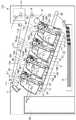
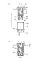
先ず、本実施例に係る電子写真画像形成装置(画像形成装置)の一実施例の全体構成について図2を用いて説明する。図2は、本実施例の画像形成装置100の概略断面図である。(About the image forming device body)
First, the overall configuration of an embodiment of the electrophotographic image forming apparatus (image forming apparatus) according to this embodiment will be described with reference to FIG. FIG. 2 is a schematic cross-sectional view of the
図2に示すように、画像形成装置100は複数の画像形成部を備える。具体的には、イエロー(Y)、マゼンタ(M)、シアン(C)、ブラック(K)の各色の画像を形成するための第一、第二、第三、第四の画像形成部SY、SM、SC、SKを有する。本実施例では、第一から第四の画像形成部SY、SM、SC、SKは、鉛直方向と交差する方向に一列に配置されている。 As shown in FIG. 2, the
なお、本実施例では、第一から第四の画像形成部の構成及び動作は、形成する画像の色が異なることを除いて実質的に同じである。従って、以下、特に区別を要しない場合は、Y、M、C、Kは省略して、総括的に説明する。 In this embodiment, the configurations and operations of the first to fourth image forming portions are substantially the same except that the colors of the formed images are different. Therefore, when no distinction is required below, Y, M, C, and K will be omitted and a general description will be given.
即ち、本実施例では、画像形成装置100は、4個の感光ドラム1(1Y、1M、1C、1K)を有する。感光ドラム1は、図示矢印A方向に回転する。感光ドラム1の周囲には帯電ローラ2及びスキャナユニット(露光装置)3が配置されている。 That is, in this embodiment, the
ここで、帯電ローラ2は、感光ドラム1の表面を均一に帯電する帯電手段である。そして、スキャナユニット3は、画像情報に基づきレーザーを照射して感光ドラム1上に静電像(静電潜像)を形成する露光手段である。また、感光ドラム1の周囲には、現像装置(以下、現像ユニット)4(4Y、4M、4C、4K)及びクリーニング手段(クリーニング部材)としてのクリーニングブレード6(6Y、6M、6C、6K)が配置されている。 Here, the charging roller 2 is a charging means that uniformly charges the surface of the
さらに、4個の感光ドラム1に対向して、感光ドラム1上のトナー像を記録材12に転写するための中間転写体としての中間転写ベルト5が配置されている。 Further, an
なお、本実施例では、現像ユニット4は、現像剤として非磁性一成分現像剤、即ち、トナーTを用いる。 In this embodiment, the developing
また、本実施例では、現像ユニット4は、現像剤担持体としての現像ローラ17を感光ドラム1に対して接触させて接触現像を行うものである。感光ドラム1は電子写真感光体(以下、単に感光体と呼ぶ)である。 Further, in this embodiment, the developing
本実施例では、クリーニングユニット13は、感光ドラム1と、帯電ローラ2、クリーニング部材としてのクリーニングブレード6を有する。また、クリーニングブレード6によって除去された感光体ドラム1上に残留していた転写残トナー(廃トナー)を収容する収納部としての廃トナー収容部14a(14aY、14aM、14aC、14aK)を有する。 In this embodiment, the
さらに本実施例では、現像ユニット4およびクリーニングユニット13を、一体的にカートリッジ化して、プロセスカートリッジ7を形成している。プロセスカートリッジ7は、画像形成装置本体に設けられた不図示の装着ガイド、位置決め部材などの装着手段(ガイド、案内機構)を介して、画像形成装置100に着脱可能となっている。 Further, in this embodiment, the developing
本実施例では、各色用のプロセスカートリッジ7は全て同一形状を有している。各色用のプロセスカートリッジ7内には、それぞれイエロー(Y)、マゼンタ(M)、シアン(C)、ブラック(K)の各色のトナーT(TY、TM、TC、TK)が収容されている。 In this embodiment, the
中間転写ベルト5は、全ての感光ドラム1に当接し、図示矢印B方向に回転する。中間転写ベルト5は、複数の支持部材(駆動ローラ87、二次転写対向ローラ88、従動ローラ89)に掛け渡されている。 The
中間転写ベルト5の内周面側には、各感光体ドラム1に対向するように、一次転写手段としての、4個の一次転写ローラ8(8Y、8M、8C、8K)が並設されている。また、中間転写ベルト5の外周面側において二次転写対向ローラ88に対向する位置には、二次転写手段としての二次転写ローラ9が配置されている。 On the inner peripheral surface side of the
画像形成時には、先ず、感光体ドラム1の表面が帯電ローラ2によって一様に帯電される。次いで、スキャナユニット3から発された画像情報に応じたレーザー光によって、帯電した感光体ドラム1の表面が走査露光される。これにより、感光体ドラム1上に画像情報に従った静電潜像が形成される。次いで、感光体ドラム1上に形成された静電潜像は、現像ユニット4によってトナー像として現像される。つまり感光体ドラム1は、その表面にトナーで形成された像(トナー像)を担持する回転体(像担持体)である。感光体ドラム1上に形成されたトナー像は、一次転写ローラ8の作用によって中間転写ベルト5上に転写(一次転写)される。 At the time of image formation, first, the surface of the
例えば、フルカラー画像の形成時には、上述のプロセスが、第一から第四の画像形成部SY、SM、SC、SKにおいて順次に行われる。各画像形成部で形成されたトナー像は、中間転写ベルト5上に順次に重ね合わせて一次転写される。その後、中間転写ベルト5の移動と同期して記録材12が二次転写部へと搬送される。そして、記録材12を介して中間転写ベルト5に当接している二次転写ローラ9の作用によって、中間転写ベルト5上の4色トナー像は、一括して記録材12上に二次転写される。 For example, when forming a full-color image, the above-mentioned processes are sequentially performed in the first to fourth image forming units SY, SM, SC, and SK. The toner images formed in each image forming portion are sequentially superposed on the
トナー像が転写された記録材12は、定着手段としての定着装置10に搬送される。定着装置10において記録材12に熱及び圧力を加えられることで、記録材12にトナー像が定着される。また、一次転写工程後に感光体ドラム1上に残留した一次転写残トナーは、クリーニング部材としてのクリーニングブレード6によって除去され、回収される。 The
除去された残留トナー(以下廃トナーと呼ぶ)は、プロセスカートリッジ7から装置本体100へと受け渡され、装置本体100に設置された廃トナーボックス86へと搬送される。 The removed residual toner (hereinafter referred to as waste toner) is delivered from the
なお、画像形成装置からカートリッジのように着脱自在に設けられたユニットを除く部位を画像形成装置本体(装置本体)と呼び、画像形成装置と区別する場合もある。 The portion of the image forming apparatus excluding the detachably provided unit such as a cartridge is referred to as an image forming apparatus main body (device main body), and may be distinguished from the image forming apparatus.
[プロセスカートリッジについて]
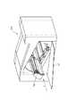
次に、本実施例の画像形成装置100に装着されるプロセスカートリッジ7の全体構成について図3を用いて説明する。図3は現像ユニット4とクリーニングユニット13を示す分解斜視図である。[About process cartridges]
Next, the overall configuration of the
プロセスカートリッジ7は現像装置4、クリーニングユニット13が一体となって形成されている。図3に示すように、現像ユニット4は、軸受部材19R、19Lに設けられた、穴19Ra、19Laを備える。また、クリーニングユニット13は、クリーニングユニット13の枠体に設けられた穴13a(13aR、13aL(不図示)、図3参照)を備える。そして、現像ユニット4とクリーニングユニット13は、穴19Ra、19Laと穴13aR、13aLに嵌合する軸24(24R、24L)を中心に回動自在に結合されている。また、現像ユニット4は、加圧バネ25により付勢されている。そのため、プロセスカートリッジ7の画像形成時においては、現像ユニット4は軸24を中心に矢印F方向に回転し、感光ドラム1と現像ローラ17は当接する。現像ローラ17は、その表面にトナー(現像剤)を担持して回転する回転体(現像剤担持体、現像部材)である。現像ローラ17は、感光体ドラム1にトナーを供給することで、感光体ドラム1の潜像を現像する。 The
(現像ユニットについて)
次に、本実施例のプロセスカートリッジ7に係る現像装置4について図4を用いて説明する。図4はプロセスカートリッジの主断面図である。(About the development unit)
Next, the developing
現像ユニット4は、現像ユニット4内の各種要素を支持する現像枠体18を有する。現像ユニット4には、感光ドラム1と接触して図示矢印D方向(反時計方向)に回転する現像剤担持体としての現像ローラ17が設けられている。現像ローラ17は、その長手方向(回転軸線方向)の両端部において、現像軸受19(19R、19L、図3参照)を介して、回転可能に現像枠体18に支持されている。ここで、現像軸受19(19R、19L、図3参照)は、現像枠体18の両側部にそれぞれ取り付けられている。現像枠体18、現像軸受19はともにカートリッジ7を構成する枠体であって、より詳細に言うと、現像ユニット4を形成する枠体である。これらの枠体によって、現像ユニットに設けられた現像ローラ17などの各部材が支持される。 The developing
また、現像ユニット4は、図4に示すように、現像剤収納室(以下、トナー収納室)18aと、現像ローラ17が配設された現像室18bを有する。トナー収容室18aや現像室18bは現像ユニット4の枠体によって形成される。 Further, as shown in FIG. 4, the developing
現像室18bには、現像ローラ17に接触して矢印E方向に回転する現像剤供給部材としてのトナー供給ローラ20と、現像ローラ17のトナー層を規制するための現像剤規制部材としての現像ブレード21が配置されている。トナー供給ローラ20は現像ローラ17にトナーを供給するローラである。トナー供給ローラ20はその表面にトナーを担持して回転する回転体であり、トナー供給部材である。
現像ブレード21は、支持部材22に対し、例えば溶接され一体化されている。また、現像枠体18のトナー収納室18aには、収容されたトナーを撹拌するとともに前記トナー供給ローラ20へトナーを搬送するための撹拌部材23が設けられている。In the developing
The developing
(クリーニングユニットについて)
次に、本実施例のプロセスカートリッジ7に係るクリーニングユニット13について図3、図4を用いて説明する。(About the cleaning unit)
Next, the
図4に示すように、クリーニングユニット13は、クリーニングユニット13内の各種要素を支持する枠体としてのクリーニング枠体14を有する。クリーニング枠体14には、軸受部材27(27Rおよび27L、図3参照)を介して感光ドラム1が図4に示す矢印A方向に、回転可能に取り付けられている。クリーニング枠体14や軸受部材27はカートリッジ7の枠体の一部であり、詳細に言うとクリーニングユニット13を構成する枠体である。これらの枠体によってクリーニングユニット13に設けられた感光体ドラム1等の各部材が支持される。 As shown in FIG. 4, the
また、クリーニング枠体14には、帯電ローラ軸受15が、帯電ローラ2の回転中心と感光ドラム1の回転中心とを通る線に沿って、取り付けられている。 Further, a charging
ここで、帯電ローラ軸受15は、図3に示す矢印C方向に移動可能に取り付けられている。帯電ローラ2の回転軸2aは、帯電ローラ軸受15に回転可能に取り付けられている。そして、帯電ローラ軸受15は、付勢手段としての帯電ローラ加圧バネ16により感光ドラム1に向かって付勢される。 Here, the charging
また、クリーニングブレード6は、図4に示すように、一次転写後に感光ドラム1の表面に残った転写残トナー(廃トナー)を除去するための弾性部材6aと、弾性部材を支持するための支持部材6bとが一体に形成されている。クリーニングブレード6は、感光ドラム1の長手方向の両端部をクリーニング枠体14にビス等の手段で固定されている。 Further, as shown in FIG. 4, the
クリーニングブレード6によって感光ドラム1の表面から除去された廃トナーは、クリーニングブレード6とクリーニング枠体14により形成される空間を重力方向に落下し、廃トナー収容部14a内に一時的に収容される。 The waste toner removed from the surface of the
廃トナー収容部14a内には、搬送部材(カートリッジ側搬送部材側)としての搬送スクリュー26が配置されている。これにより、廃トナー収容部に回収された廃トナーは搬送スクリュー26によって、プロセスカートリッジ7の長手方向一端側に搬送される。なお、プロセスカートリッジ7の長手方向は感光ドラム1の回転軸線方向と略平行とみなすことができる。 A
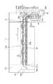
廃トナーの長手方向への搬送について、図5を用いて説明する。図5は、プロセスカートリッジ7の廃トナー排出構成を示す概略断面図である。 The transport of waste toner in the longitudinal direction will be described with reference to FIG. FIG. 5 is a schematic cross-sectional view showing a waste toner discharge configuration of the
搬送スクリュー26によって矢印H方向へと搬送された廃トナーは、プロセスカートリッジ7の長手方向端部に設置されている第一カップリング29、第二カップリング30、および連結部材32を通じて、装置本体の廃トナー受入口80dに搬送される。 The waste toner conveyed in the direction of arrow H by the
ここで、搬送スクリュー26によって矢印H方向へと搬送されるトナーの経路を第一搬送経路51とよぶ。またカートリッジ7の長手方向一端側に設けられて、第一搬送路と交差(直交)するトナーの経路(第一カップリング29以降の経路)を第二搬送経路61と呼ぶこととする。 Here, the path of the toner conveyed in the direction of arrow H by the
(装着動作の概略について)
次に、プロセスカートリッジ7の画像形成装置本体100への装着動作に関して、図6を用いて説明する。図6は装置本体100の前扉91を開いた状態の斜視図である。(About the outline of mounting operation)
Next, the operation of mounting the
プロセスカートリッジ7は、画像形成装置本体100の前扉91を開け矢印J方向に差し込まれる。その後、装置本体奥側の不図示の後側板に突き当たって挿入が完了される。その後、装置本体100の前扉91を閉じることで、連結部材32が装置本体100の廃トナー受入口80d(図5参照)と連結し、装着動作が完了する。詳細は後述するが、連結部材32は、廃トナーを排出するためにカートリッジ7に設けられた排出路(第二搬送路61)を、画像形成装置本体100に連結するための連結部)である。 The
[カートリッジと本体の廃トナー部連結説明]
[シャッタの構成について]
次に、連結部材32に設置されたシャッタ(開閉部材)34の装着時の動きについて、図3、図7を用いて説明する。図7は、シャッタ支持構成を説明する正面図、および斜視図である。プロセスカートリッジ7の装着方向(矢印J方向)奥側には、前述した廃トナー排出口である連結部材32が設けられている。(図3参照)
ここで、図7に示すように、連結部材32には、軸線方向に突出した凸形状のガイド部32b、32cが設けられている。また、シャッタ34には、溝部34a、34bが断面方向両端に配置されている。なお断面方向とは、感光体ドラム1の軸線と垂直なカートリッジの断面に沿った方向である。[Explanation of connection between the cartridge and the waste toner part of the main body]
[Shutter configuration]
Next, the movement of the shutter (opening / closing member) 34 installed on the connecting
Here, as shown in FIG. 7, the connecting
シャッタ34は、溝部34a、34bを凸形状のガイド部32b、32cにガイドされた状態で係合し、装着方向(矢印J方向)に移動可能に支持されるとともに、廃トナー排出部32dを封止している。 The
また、シャッタ34は、廃トナー排出部32dを封止するための弾性シール部材35を備える。シャッタ34は、弾性シール部材35が排出口32dに押しつぶされる状態で支持されている。このため、連結部材32の排出口32dは、図7(a)に示すように弾性シール部材35によって隙間なく塞がれ、廃トナーの封止が可能となっている。 Further, the
さらにシャッタ34はクリーニング枠体14に設置された付勢部材36によって、装着方向奥側(矢印J方向)へと付勢されている。シャッタ34は、付勢部材36によって、排出口突き当て部34dが、廃トナー連結部材32の突き当て部32eに突き当たる。こうして、プロセスカートリッジ7上で、シャッタ34は、連結部材32によって位置決め支持される。 Further, the
さらに、クリーニング枠体14には、シャッタ34を装着方向に移動可能に支持するシャッタガイド部14aが、連結部材32のガイド部32bと断面方向同一位置に、装着方向(矢印J方向)に延伸して設置されている。 Further, in the
シャッタ34のシャッタ係合部34a、34bは、連結部材32の突き当て部32eに突き当たった状態で、クリーニング枠体14のシャッタガイド部14aに一部係合支持されている。言い換えると、シャッタ34は、連結部材32とクリーニング枠体14の両方に係合支持されている。 The
また、図7(b)に示すように、シャッタ34は装置本体100への装着時に、プロセスカートリッジ7内で挿入方向と反対側(矢印J反対方向)へ移動する。このように、シャッタ34は廃トナーを排出する開口(排出口)に対し開閉可能に設けられている。 Further, as shown in FIG. 7B, the
シャッタ34は矢印J反対方向へ移動することで、連結部材32のシャッタガイド部32b、32cとの係合が完全に外れる。そして、シャッタ34はクリーニング枠体14のガイド部14aのみに係合支持される状態となる。このため、装置本体100への装着完了状態では、シャッタ34は連結部材32の断面方向(矢印N方向)の移動を阻害しない。 By moving the
次に、連結部材32と装置本体100の廃トナー受入口80dとの接続方法について説明する。 Next, a method of connecting the connecting
(廃トナー排出路と装置本体とを連結するための連結部材の動作について)
装置本体100の前扉91(図6参照)を閉めた際の廃トナー連結部材の動きを、図8を用いて説明する。図8は前扉開閉時の連結部材の動作を説明する模式図である。(About the operation of the connecting member for connecting the waste toner discharge path and the main body of the device)
The movement of the waste toner connecting member when the front door 91 (see FIG. 6) of the apparatus
画像形成装置100の装着方向奥側には、本体前扉91と不図示のリンク機構で回転移動するアーム42が設置されている。プロセスカートリッジ7の連結部材32には、装置本体100のアームに当接するアーム当接部32f、32gが断面方向に突出して2か所設置されている。(図8(a)参照)プロセスカートリッジ7が装置本体100の後側板98に突き当たった状態で、アーム42の当接部42a、42bはアーム当接部32f、32gの上方方向に位置するように配置されている。(図8(b)参照)
また、プロセスカートリッジ7の装着方向突き当て時には、アーム42の当接部42a、42bが、連結部材32のアーム当接部32f、32gに装着方向(矢印J方向)で約4mmオーバラップした位置に配置される。また、アーム42はアーム回転軸42cを、後側板98の支持穴98e、98fによって回転可能に支持されている。装置本体100の前扉閉動作に伴い、アーム42は不図示のリンク機構によってアーム回転軸42cを中心に矢印M方向に約42度回転される。On the back side of the
Further, when the
アーム42の回転動作に伴って、アーム42は連結部材32のアーム当接面32f、32gに突き当たる。そして、連結部材32は、アーム42の回転動作によって、矢印N方向へと移動し、本体トナー受入口80d側(矢印N方向)と連結する連結位置(第1の位置、進出位置)へと至る。 As the
ここで、連結部材32は本実施例では、アーム42の回転動作によって矢印N方向に約7.7mmの距離を移動する。 Here, in this embodiment, the connecting
こうして、アーム42によって押し下げられた連結部材32は、装置本体100の廃トナー受入口80dへと約4mm侵入する。 In this way, the connecting
以上の動作によって、連結部材32と装置本体100の廃トナー受入口80dとの接続がなされる。 By the above operation, the connecting
[廃トナー排出部の駆動連結について]
(廃トナー駆動連結構成について)
次に廃トナー排出部の装置本体100との駆動連結について図9を用いて説明する。[About drive connection of waste toner discharge part]
(About waste toner drive connection configuration)
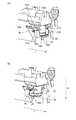
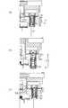
Next, the drive connection of the waste toner discharging unit with the apparatus
図9は、連結部材32と本体廃トナー受入口80dの連結方法を説明する断面図である。図9(b)は、連結部材32は、装置本体100の不図示の前扉の閉動作に伴い、廃トナー受入口80dに侵入した状態の断面図である。 FIG. 9 is a cross-sectional view illustrating a method of connecting the connecting
図9に示すように、装置本体100には、プロセスカートリッジ7からの排出トナーを受け入れる廃トナー受入口80dが設置されている。 As shown in FIG. 9, the apparatus
ここで、廃トナー受入口80dには、シール部材47が設置されている。シール部材47は、例えばゴムスポンジ、発泡ウレタン等の弾性を有するシール部材である。プロセスカートリッジ7の連結部材32が押し下げられると、連結部材32は排出トナー受入口80dに設置された本体受入口シール部材47へ侵入する。 Here, a
また、連結部材32にはテーパ形状32kが設けられており、連結部材32と、廃トナー受入口80dの軸線方向の位置ずれを吸収できるようになっている。 Further, the connecting
さらに、連結部材32にはつば形状のリブ部32l(図8参照)が設置されており、廃トナー受入口80dに装着された際に、矢印N方向での隙間を塞ぐフタの役割をする。また、図9に示すように、本体廃トナー搬送部80は、廃トナー受入口80dを有する本体第一搬送路80a、廃トナーを装置本体100の廃トナー容器14に送り出すための第二搬送路80bが設けられている。 Further, a brim-shaped rib portion 32l (see FIG. 8) is installed in the connecting
本体第一搬送路80aには、バネ押え43が受入口付近に設置されている。本体第一搬送路80a内部の弾性力を有するバネカップリング44は、バネ部44aでバネ押え43と突き当たることで支持されている。さらに、バネカップリング44は、本体側搬送部材としての搬送フィン45と回転方向一体に取り付けられている。搬送フィン45は回転軸45aを有し、回転軸45aは本体搬送部材のフィン軸受部80eに嵌めこまれ、回転可能に支持されている。このためバネカップリング44は、中心線61aを中心に回転可能に支持されている。 A
連結部材32が廃トナー受入口80dに侵入(進入)することで、廃トナー連結部材は、バネカップリング44の反力に逆らい、バネカップリング44を下方向(廃トナー連結口侵入方向)に押しつぶす。 When the connecting
さらに、バネカップリング44は連結部材32内の第二カップリング部材30と付勢力を持って突きあたる。突き当たった第二カップリング部材30は、感光ドラム1の回転に連動して回転する部材である。 Further, the
第二カップリング部材30が軸線61aを中心に回転することで、バネカップリング44は、第二カップリング部材30と回転方向に係合し、搬送フィン45と一体で回転する。 When the
第二カップリング部材30は、カートリッジ7から駆動力を出力してバネカップリング44を回転駆動させる駆動出力部(出力カップリング、カートリッジ側カップリング)である。一方、バネカップリング44は、カートリッジ7から駆動力が入力される駆動入力部(入力カップリング、画像形成装置本体側カップリング)である。 The
[カートリッジ内の駆動構成について]
(廃トナー搬送スクリューの動作について)
次に、前述した感光体ドラム1から第二カップリング部材30への駆動伝達について説明する。まず、感光体ドラム1から、廃トナー搬送スクリュー26への駆動伝達経路について、図10を用いて説明する。[About the drive configuration in the cartridge]
(About the operation of the waste toner transfer screw)
Next, the drive transmission from the
図10は、感光体ドラム1から廃トナー第二カップリング30への駆動連結構成を説明する部品概略図である。 FIG. 10 is a schematic view of parts for explaining a drive connection configuration from the
図10に示すように、感光ドラム1の一端には、装置本体100からの駆動を受けるカップリング部1cが配置されている。また、他端部には、後述する廃トナー搬送スクリュー26に駆動を伝達するための感光ドラムギア1bが設けられている。 As shown in FIG. 10, a
また、図10に示すように、ドラム軸受27(図3参照)に回転可能に支持されたアイドラギア52および搬送スクリューギア53が感光ドラム1の軸線方向の一端側に配置される。 Further, as shown in FIG. 10, an
搬送スクリューギア53は搬送スクリュー26に駆動伝達可能に係合している。画像形成装置100の入力部からクリーニングユニット13一端のカップリング部1cに回転駆動力が伝達される。伝達された回転駆動力は、感光ドラムギア1b、アイドラギア52、搬送スクリューギア53が順次噛み合うことで、感光ドラム1から搬送スクリュー26へと伝達される。廃トナー収容室14aに収容された廃トナーは、搬送スクリュー26が矢印G方向に回転することで、搬送スクリュー部26aによって矢印H方向へと搬送される。 The
こうして、感光体ドラム1から廃トナースクリュー26への駆動伝達がなされる。廃トナースクリュー26の回転駆動力は、廃トナースクリュー26の長手一端に配置された第一カップリング部材29へと伝達される。 In this way, the drive is transmitted from the
(第一カップリング部材の動作について)
次に、前述した廃トナー搬送スクリュー26から、第一カップリング部材29への駆動伝達について、図11を用いて説明する。(About the operation of the first coupling member)
Next, the drive transmission from the waste
図11はプロセスカートリッジ7内での搬送スクリュー26と第一カップリング部材29との係合を中心線61a(図9参照)の上方向から見た概略図である。 FIG. 11 is a schematic view of the engagement between the
図11に示すように、第一カップリング部材29には駆動ピン29bが複数設けられている。また、搬送スクリュー26には、駆動伝達羽根26gが設けられている。 As shown in FIG. 11, the
廃トナースクリュー26が矢印G方向に回転すると、駆動伝達羽26gは矢印S方向へ移動する。矢印S方向に移動する駆動伝達羽26gと、第一カップリング部材29上の複数の駆動ピン29bの一つ(29b1)が係合し、矢印S方向へ押しだされる。この力によって第一カップリング部材29は、中心線61aを中心として、矢印T方向へ回転駆動する。 When the
ここで、駆動ピン29bは、カップリング29の軸線を中心として一定角度間隔で配置された円筒凸形状である。本実施例では、直径1.8mmの駆動ピン29bが60度毎に合計6つ設置されている。 Here, the drive pins 29b have a cylindrical convex shape arranged at regular angular intervals about the axis of the
搬送スクリュー26の軸線に対し、駆動伝達羽26gと接触可能な範囲に駆動ピン29bが2つ(29b1,29b2)存在する位相状態から説明する。((図11(a)))
駆動伝達羽26gは、駆動ピン29bの回転方向T下流側で駆動ピン29b1をT方向へと回転移動させる。駆動ピン29b1が、駆動伝達羽根26gの駆動伝達範囲から外れると、続いて駆動伝達ピン29b1より回転方向上流側にある駆動伝達ピン29b2が駆動伝達羽根26gに接触される。(図11(a))
駆動伝達羽根26gがさらに、矢印S方向へ動くことで、第一カップリング部材29の駆動伝達ピン29b2が矢印S方向へと移動される。(図11(b))
こうして、第一カップリング部材29は矢印T方向へと回転する。これによって、再び回転上流の駆動ピン29bが駆動伝達羽根26gと係合可能な位置まで移動してくることとなる。(図11(a))
以上の動作を繰り返すことで、第一カップリング部材29は、搬送スクリュー26の回転によって回転移動を続けることとなる。This description will be described from the phase state in which two drive
The
When the
In this way, the
By repeating the above operation, the
ここで、第一カップリング部材29中心から、搬送スクリュー26の軸線方向に対し、垂直方向に降ろした線を線Xとする。線Xを中心として、両側に同一角度Yで駆動ピン29bが二つ存在する時に、駆動ピン29b1と、駆動ピン29b2が、搬送スクリュー26の軸線方向で最も離れた位置となる。また、この時の駆動ピン29b1と29b2との軸方向軸間距離をZとする。(図11(a)参照)
廃トナースクリュー26の軸線方向でみた駆動ピン29b間距離Zに対し、駆動伝達羽26gのスクリューのピッチは大きくなっている。Here, a line drawn from the center of the
The pitch of the screw of the
そのため、駆動伝達羽根26gと駆動ピン29bが係合して駆動ピン29bを連続して押し続けることができるようになっている。 Therefore, the
なお、駆動ピン29bの搬送スクリュー26軸線方向でのピッチ(距離Z)と搬送スクリュー26のピッチが近いほど、第一カップリング部材29は連続的に(滑らかに)回転させることができる。 The closer the pitch (distance Z) of the
こうして、感光ドラム1の回転駆動が、廃トナースクリュー26を経由し、感光ドラム1の軸線と直交方向(第二搬送路61の中心線61a)中心の回転に変換され第一カップリング部材29へと伝達される。 In this way, the rotational drive of the
なお、本実施例では搬送スクリュー26は感光ドラム1の回転により、駆動を伝達されている。しかし、例えば、現像ローラ17の回転に連動して搬送スクリュー26が駆動する構成であっても同様の効果が得られる。 In this embodiment, the
(第二カップリング部材の動作について)
第一カップリング部材29から、第二カップリング部材30への駆動伝達について、図12、図13を用いて説明する。(About the operation of the second coupling member)
The drive transmission from the
図12は廃トナー排出部の構成を説明する分解概略図である。また、図13はカップリング受け28への第一カップリング部材29、第二カップリング部材30の取り付けを説明する断面図である。 FIG. 12 is an exploded schematic view illustrating the configuration of the waste toner discharging portion. Further, FIG. 13 is a cross-sectional view illustrating attachment of the
図12に示すように、第一カップリング部材29、第二カップリング部材30、カップリングバネ31、カップリング受け28、と連結部材32は中心線61aに沿って略同一軸線上に配置されている。また、第一カップリング部材29と第二カップリング部材30はカップリングバネ31で連結される。 As shown in FIG. 12, the
連結部材32は、カップリング受け28に対し、第二カップリング部材30とともに、カップリングバネ31の付勢力に逆らって、図12の矢印N方向に移動可能に取りついている。カップリング受け28は、第一カップリング部材29や第二カップリング部材30を内部に受け入れることで、これらを支持する支持部である、また連結部32もカップリング受け28の外周を囲うように取り付けられ、カップリング受け28によって支持される。そのためカップリング受け28は連結部材32の支持部でもある。 The connecting
図12に示すように、第一カップリング部材29は、前述した搬送スクリュー26と係合して回転する突起形状の駆動ピン29bを複数備える部材である。また、第一カップリング部材29は第二カップリング部材30に駆動を伝えるための2つの突起形状の駆動爪29cを備える。 As shown in FIG. 12, the
第一カップリング部材29の駆動爪29cがカップリング受け28の円筒部28aの内径部に嵌め込まれ、第一カップリング部材29はカップリング受け28に回転可能に支持される。ここで、駆動爪29cは、円筒形状の一部を切り欠いた形状となっている。また、第二カップリング部材30には、第一カップリング部材29の駆動爪29cから回転駆動を受ける駆動爪30fが2箇所設けられている。第二カップリング部材30は、駆動爪30fの対向方向に溝部30b、バネかけ溝部30cが設置されている。 The
駆動爪30fも、円筒形状の一部を切り欠いた形状となっている。そして、駆動爪30fの外径寸法は駆動爪29cと略同一である。図13に示すように、駆動爪30fが第一カップリング部材29の駆動爪29cと対向するように、第二カップリング部材30はカップリング受け28の円筒部28aに挿入される。 The
ここで、駆動爪29c、30fは円筒の一部が切り欠かれた突起形状と表現できるし、駆動伝達面を備える曲がった板状の形状とも表現できる。本実施例ではその外形は一辺が傾斜し、対向する他辺は回転軸と平行な台形に構成されている。なお、これらの形状は互いに駆動力を伝達しながらも、位相のずれに対して許容できる形状であればよく、本実施例の形状に限るものではない。 Here, the
一方、付勢部材としてのカップリングバネ31は、図12に示すように、先端に折り曲げ形状31a、対向方向に輪形状31bを有するねじりコイルばねである。カップリングバネ31は第二カップリング部材30へ、矢印I方向へ挿入され、折り曲げ形状31aがバネかけ溝30cにはまりこむ。 On the other hand, as shown in FIG. 12, the
さらに、第二カップリング30と係合した状態で、カップリングバネ31の円形状31bが第一カップリング部材29の溝部29fに係合(嵌合)する。 Further, in a state of being engaged with the
この時、カップリングバネ31は、自由長に対し引き延ばされた状態となる。言い換えると、カップリングバネ31は縮む方向に付勢力を与える状態となる。これにより、第一カップリング部材29と第二カップリング部材30が引き合う方向に付勢される。この付勢力によって、第一カップリング部材29の支持部29dは、カップリング受け部28の支持部28bと突き当たる。 At this time, the
また、第二カップリング部材30は、カップリング受け部28の円筒形状28aの先端部に設けられた支持部28cと駆動爪30fに設けられた突起部30dが突きあたる。そして、カップリングバネ31の付勢力を受けた状態で中心線61aの回転方向T方向で位置決め支持される。 Further, the
カップリングバネ31に付勢された状態で、第一カップリング部材29と第二カップリング部材30は、カップリング受け28の円筒部28a内周に駆動爪29c、30fを介して回転可能に支持されている。第一カップリング部材29、第二カップリング部材30は、中心線61aの矢印T方向で、係合部29e、係合部30gが係合し、一体に回転可能な構成となっている。 In a state of being urged by the
以上の構成によって、第一カップリング部材29から、第二カップリング部材30への駆動伝達がなされることとなる。 With the above configuration, drive transmission from the
以上の構成で、プロセスカートリッジ7から装置本体100への廃トナー搬送部の駆動伝達がなされることとなる。 With the above configuration, the drive transmission of the waste toner transport unit from the
次に廃トナー排出部の組み立て方法を説明する。 Next, a method of assembling the waste toner discharge unit will be described.
(カップリング受けの取り付けについて)
図12に示すように、カップリング受け28には第一カップリング部材29、第二カップリング部材30、カップリングバネ31が取り付けられる。(About the installation of the coupling receiver)
As shown in FIG. 12, a
カップリング受け28の溶着部28eは、第一カップリング部材29、第二カップリング部材30、カップリングバネ31が取りついた状態で、軸受部材27R(図3参照)に対し、溶着、接着等で取り付けられている。これにより、廃トナーの外部への洩れを低減している。 The welded
このカップリング受け28に対し、矢印I方向から、連結部材32が同軸上に嵌めこまれるように取り付けられる。 The connecting
ここで、図12に示すように、カップリング受け28には、連結部材32を軸回転方向に位置決めする回転止めリブ28dが設置されている。さらに、連結部材32には、周方向の一部に凹形状の回転位置決め溝32iが設けられている。 Here, as shown in FIG. 12, the
連結部材32を矢印I方向へと嵌め込んで行くと、連結部材32の溝32iに、カップリング受け28の回転止めリブ28dが係合する。こうして、カップリング受け28と連結部材32との軸線61aに対する回転方向の位置が規制される。 When the connecting
次に、図13を用いて廃トナー連結部32の取り付け方法について説明する。 Next, a method of attaching the waste
図13は、廃トナー排出部の組み付け方法を説明する部品断面図である。 FIG. 13 is a cross-sectional view of a part for explaining a method of assembling the waste toner discharging portion.
第二カップリング部材30には、圧縮爪30eが、円筒対向方向に2箇所設けられている。 The
また、図13に示すように、連結部材32には、第二カップリング部材30に軸方向に支持される支持部32aが設置されている。 Further, as shown in FIG. 13, the connecting
連結部材32をカップリング受け28に嵌め込んで行くと、支持部32aがカップリング受け28に支持された第二カップリング部材30の圧縮爪30eを内径方向に撓ませて侵入する。 When the connecting
さらに連結部材32を押しこむことで、支持部32aは第二カップリング部材30の圧縮爪30eを完全に乗り越え、連結部材32は支持部32aで第二カップリング部材30の圧縮爪30eによって鉛直方向で支持される。(図13(b))
この時、圧縮爪30eは支持部32aを、矢印I反対方向で確実に乗り越える必要がある。Further, by pushing the connecting
At this time, the
このためには、カップリング受け28に対し、廃トナー連結部32を矢印I方向に取り付けていった場合に、廃トナー連結部32の上面部(端部)32pと、カップリング受け28が接触する前に、圧縮爪30eが支持部32aを乗り越える必要がある。このため、廃トナー連結部32は、カップリング受け28に対し隙間Qを持って設置されている。隙間Qには、廃トナーの漏れを防止するために、シール501が設置される。シール501については後述する。 For this purpose, when the waste
[伸縮機構に関する説明]
以下に、トナー搬送路(排出路)を伸縮させる伸縮機構、伸縮動作について図13、図14を用いて説明する。[Explanation of expansion and contraction mechanism]
The expansion / contraction mechanism for expanding / contracting the toner transport path (discharge path) and the expansion / contraction operation will be described below with reference to FIGS. 13 and 14.
図14は廃トナー排出部の部品構成を説明する概略断面図である。 FIG. 14 is a schematic cross-sectional view illustrating the component configuration of the waste toner discharging portion.
前述したように、第一カップリング部材29、第二カップリング部材30は、カップリングバネ31によって矢印I方向に付勢されて連結している。(図13参照)
このため、連結部材32は、第二カップリング部材30とともに、プロセスカートリッジ7に対し、矢印N方向に移動可能である。(図14(a)、(b))
さらに、第一カップリング部材29の駆動爪29cと第二カップリング部材30の駆動爪30fは、カップリング受け28の円筒部28の内径部において回転矢印T方向で係合可能に支持されている。このため、第一カップリング部材29に対し、第二カップリング部材30が矢印N方向へと移動した状態(図14(b))でも、係合部29e、30gは回転矢印T方向で駆動伝達可能である。As described above, the
Therefore, the connecting
Further, the
カートリッジが本体内に装着され、印字動作を行っている時は、連結部材32は、第一カップリング部材29に対し、第二カップリング部材30が矢印N方向に移動した状態(駆動伝達位置のある状態、図14(b))となる。 When the cartridge is mounted in the main body and the printing operation is performed, the connecting
一方、プロセスカートリッジ7単体の時(連結部材32が退避位置にある状態:図14(a))に、カップリングバネ31(図13参照)の作用により、第一カップリング部材29と第二カップリング部材30が引き合う。それに伴い連結部材32が矢印I方向へと移動した状態となる。これにより、連結部材32の先端がプロセスカートリッジ7の外形(図16の外形線L)内に収まる。 On the other hand, when the
また、プロセスカートリッジ7の廃トナー排出部の第一カップリング部材29、第二カップリング部材30は本体接続状態(駆動連結位置)、本体退避状態(退避位置)のいずれの状態でも係合して回転をする。このため、例えばプロセスカートリッジ7の単品状態(退避位置)でも、感光ドラム1を回転させることで、第一カップリング部材29と第二カップリング部材30の係合を検査することができる。 Further, the
次に、プロセスカートリッジ7から装置本体100への廃トナーの受け渡しの経路について説明する。 Next, a route for delivering waste toner from the
(印字中の廃トナー搬送について)
クリーニングブレード6によって像担持体としての感光体1上から回収された廃トナーは、収納部としての廃トナー収容部14aに収容される。(図4参照)廃トナー収容部14aの第一搬送路51内に搬送部材(カートリッジ側搬送部材側)としての搬送スクリュー26が配置されている。これにより、廃トナー収容部に回収された廃トナーはカートリッジ側搬送部材としての搬送スクリュー26によって、プロセスカートリッジ7の長手方向一端側(矢印H方向)に搬送される(図5参照)。(About transporting waste toner during printing)
The waste toner recovered from the
搬送された廃トナーは第二搬送路61を通じて、装置本体の廃トナー受入口80dに搬送される。第二搬送路61には、第一カップリング部材29、カップリングバネ31、第二カップリング部材30、連結部材32が設けられている。 The transported waste toner is transported to the waste
連結部材32は、画像形成装置100の本体廃トナー受入口80dと連結されている。 The connecting
プロセスカートリッジ7から排出された廃トナーは、廃トナー受入口80dからバネカップリング44、本体側搬送部材としての搬送フィン45を通過し、第二搬送路80bに送られる。その後、第二搬送80b内に設けられた本体搬送スクリュー85によって画像形成装置の(本体側)収納部としての廃トナーボックス86(図2参照)に排出、収容される。 The waste toner discharged from the
次に、上記の廃トナーの受け渡し構成の詳細について説明する。 Next, the details of the above-mentioned waste toner delivery configuration will be described.
(プロセスカートリッジ内での廃トナーの流れに関する説明)
前述したように、廃トナーは廃トナースクリュー26によって感光体1の軸線方向一端(図5矢印H方向)へ向けて搬送される。図5に示すように、逆スクリュー部26eは、搬送スクリュー26の第二搬送部とみなすこともできる。つまり搬送スクリュー26は、トナーを搬送するための主要部である第一搬送部(搬送スクリュー部26a)と、その第一搬送部とは反対向きにトナーを搬送する第二搬送部(逆スクリュー部26e)を持つ。(Explanation of waste toner flow in the process cartridge)
As described above, the waste toner is conveyed by the
搬送スクリュー26の搬送スクリュー部26aは、開口部61b(図11(b)参照)に向けてトナーを搬送するための部分である。一方、第二搬送部(逆スクリュー26e)は、搬送スクリュー部26aのトナー搬送方向において、搬送スクリュー部26aより下流側に配置されている部分である。第二搬送部である逆スクリュー26eは開口部61bの近傍に配置されており、逆スクリュー26eの長さは、第一搬送部に比べて短い。 The
搬送された廃トナーは、搬送スクリュー部26aと、逆スクリュー部26eとの間で衝突し、第一カップリング部材29の穴部29aから開口部61bへと送られる(図11(a)矢印U方向)。 The conveyed waste toner collides with the conveying
また、図11に示すように、搬送スクリュー26の回転に伴い、第一カップリング部材29は矢印T方向へと回転される。穴部29aを通過した廃トナーは、第一カップリング部材29に取り付けられたカップリングバネ31の内径へと移動する(図9参照)。 Further, as shown in FIG. 11, the
また、図9に示すように、廃トナーは第一カップリング部材29と係合する第二カップリング部材30の穴部30aへ移動する。同時に、第一カップリング部材29の回転に伴って、係合部29eから第二カップリング部材30の係合部30gへ駆動が伝達される。このため、第一カップリング部材29、第二カップリング部材30とカップリングバネ31が一体的に回転する。 Further, as shown in FIG. 9, the waste toner moves to the
ここで、カップリングバネ31は、回転する際に廃トナーを図9の矢印N方向へと搬送する方向に巻かれている。このため、廃トナーは、矢印N方向へ、自由落下するとともに、搬送力を持って矢印N方向へ積極的に搬送される。さらにカップリングバネ31が、矢印T方向に回転することで、廃トナーをほぐす効果も発生する。このため、廃トナーの搬送(移動)をよりスムーズに行うことが可能となる。 Here, the
カップリングバネ31、第二カップリング部材30の穴部30aを通過した廃トナーは、第二カップリング部材30に矢印N方向で支持された連結部材32の廃トナー排出部32dより排出される。以上が、プロセスカートリッジ7内での廃トナーの排出までの動きである。 The waste toner that has passed through the
(廃トナー排出部下流側における廃トナーの流れ)
図9に示すように、廃トナー排出部32dから排出された廃トナーは、廃トナー排出部32d下部に配置された画像形成装置本体100が備える廃トナー受入口80dから第一搬送路80aを経て、第二搬送路80bへ入る。(Flow of waste toner on the downstream side of the waste toner discharge part)
As shown in FIG. 9, the waste toner discharged from the waste
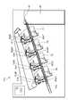
図15は、装置本体100内の廃トナー搬送方法を説明する背面部の断面図である。 FIG. 15 is a cross-sectional view of a back surface portion for explaining a method of transporting waste toner in the apparatus
図15に示すように、廃トナー受入口80d、および、第一搬送路80aは、プロセスカートリッジ7の数に対応して複数設けられており(80aY、80aM、80aC、80aK)、各色連通した搬送路80bへと、廃トナーを送り出している。 As shown in FIG. 15, a plurality of waste
搬送路80bに入った廃トナーは、搬送路80b内の搬送部材としての本体搬送スクリュー85によって廃トナーボックス86に排出される。 The waste toner that has entered the
次に、プロセスカートリッジ7の廃トナー搬送構成の配置、組立の詳細を説明する。 Next, the details of the arrangement and assembly of the waste toner transfer configuration of the
(搬送路の配置とその断面について)
廃トナー搬送構成の配置について図11、図16を用いて説明する。図16は、第二搬送路61の中心線61aを中心とした搬送スクリュー26と排出口32dの位置関係を示す断面図である。(About the arrangement of the transport path and its cross section)
The arrangement of the waste toner transport configuration will be described with reference to FIGS. 11 and 16. FIG. 16 is a cross-sectional view showing the positional relationship between the
図16(a)に示すように、第二搬送路61の中心線61aは、第一搬送部材26の軸中心26aと、感光ドラム1の軸中心1aとの間を通るように配置されている。 As shown in FIG. 16A, the
つまり中心線61aに対して感光体ドラム1の回転中心1aと、第一搬送部材26の回転中心は互いに反対側に位置する。 That is, the
なお中心線61aは、第二カップリング部材30の回転軸線とほぼ同一の直線である。つまり感光体ドラム1の回転中心1aと、廃トナー搬送スクリュー26の回転中心は第二カップリング部材30の回転軸線(軸線61a)に対して互いに反対側にある。 The
上記のような配置関係を満たすことにより、感光体ドラム1や廃トナー搬送スクリュー26や、第二搬送路(排出路)61を小さいスペースに配置できる。そのため、クリーニング枠体14の外形線L(図3参照)からの突出量を減らす、或いは、なくすことができる。そのため、感光体ドラム1の軸線方向からみたときのクリーニングユニット又はプロセスカートリッジを小型化することができる。 By satisfying the above arrangement relationship, the
また、図11(b)、図16(a)に示すように、中心線61a方向から見て、第二搬送路61の開口部61bは、搬送スクリュー26の回転時に逆スクリュー部26eがとりうる領域と範囲Kにおいてオーバラップするように配置している。開口部61bは、第一搬送路51と第二搬送路61が連通する連通部である。 Further, as shown in FIGS. 11B and 16A, the
これにより、搬送スクリュー26の搬送力により、第一搬送路51から第二搬送路61へ廃トナーをスムーズに搬送することができる。
また、図16(a)に示すように、カートリッジの長手方向(図の左右方向)において第一搬送路51と、第二搬送路61がオーバラップする。これにより、廃トナーの搬送に必要な搬送路の径を確保しながら、クリーニングユニット13の長手方向の幅を縮めることができる。その結果、プロセスカートリッジ7の小型化が可能となる。As a result, the transport force of the
Further, as shown in FIG. 16A, the
(連結部のシール構成について)
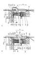
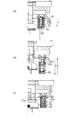
図1は本実施例に記載するシールの設置部を示す断面図、図17は、装置本体に接続していない状態での廃トナー搬送路の隙間を示す断面図である。(About the seal configuration of the connecting part)
FIG. 1 is a cross-sectional view showing a seal installation portion described in this embodiment, and FIG. 17 is a cross-sectional view showing a gap of a waste toner transport path in a state where the seal is not connected to the main body of the apparatus.
図1に示すように、カップリング受け28の円筒部28aには、廃トナー連結部32が同軸(61a)上に設置されている。廃トナー連結部32はカップリング受け28の円筒部28aに隙間を持ってはまり込むように設置されている。また、廃トナー連結部32は矢印N方向に移動可能にカップリング受け28上に設置されている。 As shown in FIG. 1, a waste
前述したように、廃トナー連結部32は、カップリング受け28に対し隙間Qを持って設置されている。隙間部Qには、弾性を有するシール501が設置されている。シール501は、トナーの排出路を風刺することで、カートリッジの外部にトナーが漏れるのを抑える部材(封止部、封止部材)である。シール501の例としては、発泡したポリプロピレンや発泡したウレタンフォームなどがある。 As described above, the waste
シール501は弾性を有し、前述したように、廃トナー連結部32を組み付ける際に、廃トナー連結部32を矢印I方向に装着していくことで、矢印I方向に圧縮される。この時、隙間Qに設置されたシール501は、連結部材32の上面部32pに圧縮されることで、組み立て性を阻害することなく、隙間Qを塞ぐことが可能である。なお上面部32pは、排出口32dから排出されるトナーの移動方向(矢印N方向)において連結部材32の上流側に設けられた端部である。ちなみに本実施例でぇあトナーの移動方向Nは、進出位置(連結位置:図16(b)参照)に移動する際の連結部材32の移動方向と実質的に同様の方向である。逆に言うと、トナーの移動方向Nは、退避位置(図16(a)参照)にむかって移動する連結部材32の移動方向Iとは実質的に反対の方向である。 The
次にシール501の設置方法について、図18、図19を用いて説明する。 Next, a method of installing the
図18はシール501のカップリング受け28への設置方法を説明する外観斜視図、図19はシール501の外観図である。 FIG. 18 is an external perspective view illustrating a method of installing the
図18に示すように、カップリング受け28には、面28gに対し、凹形状となるシール設置溝28hが、円筒部28aの外周に配置されている。さらに、カップリング受け28には、シール501を係止するための溝部28j、凹形状の穴部28kが設置されている。 As shown in FIG. 18, in the
図18に示すように、シール501は、カップリング受け28の円筒部28aにはまり込む穴形状501aを持つ円筒形状で形成されている。穴径上の一部にはカップリング受け28の凸形状の回転止めリブ28dにはまり込む位置に、凹部501bが配置されている。さらに、シール501には円筒形状501aの回転方向でカップリング受け28に対し位置決めを行うための凸形状501cが設置されている(図19参照)。凸形状501cは、細部501dを根元に、太部501eを有する突起形状となっている。 As shown in FIG. 18, the
図18(a)に示すように、シール501をカップリング受け28に対し、矢印I方向に装着していく。シール501の穴形状501aが、カップリング受け28の円筒部28aにはめ込まれると同時に、シール501の凹部501bが、回転止めリブ28dにはめ込まれることで、円筒形状での回転方向の位置を決められながら、面28gまで差し込まれていく。 As shown in FIG. 18A, the
シール501が面28gまで到達した後(図18(b))、シール501をさらに圧縮すると、シール設置溝28hに円筒形状のシール501が入り込んでいく。この際に、シール501の外径501fはシール設置溝28hの外周よりわずかに大きく作られており、シール501の弾性により、カップリング受け28に対して外径差分の圧縮によって係止される。さらに、シール501の凸形状の太部501cを凹形状の溝部28jにはめ込むことで、シールの細部501dがシール設置溝28jに圧入状態で押し込まれる。 After the
こうして、細部501dがシール設置溝28jへ圧入される力、および、シール設置溝28hでのシール501の弾性による保持力により、シール501はカップリング受け28に対し矢印N方向に抜けることなく、設置される。 In this way, due to the force with which the
また本実施例では、シールの弾性を用いてカップリング受け28に対する設置を行う構成を説明している。すなわちカップリング受け28に設けられた凹部(シール設置溝28h)に、シール501が圧縮されながらはまり込み、この凹部(窪み)にシール部材501が固定される。つまりjカップリング受け28の凹部(シール設置溝28h)にシール501が圧入されている。しかしながらシール(封止部)を固定するための構成は、このようなものに限られるわけではない。たとえば、シール501のカップリング受け28の設置面側に粘着剤、接着材等を用いて接着する(貼り付ける)構成をとることも可能である。あるいは、このような接着と圧入を同時に行ってもよい。 Further, in this embodiment, a configuration in which the
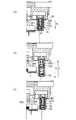
次に、カップリング受け28にシール501を設置した状態での、装置本体へ接続した際の動きについて図20を用いて説明する。 Next, the movement when the
図20(a)は、装置本体100にプロセスカートリッジ7を設置した際のプロセスカートリッジのみの断面図。図20(b)は、装置本体100とカートリッジ7の連結状態時の断面図。図20(c)は、連結状態から、再び連結解除した際の断面図を示す。 FIG. 20A is a cross-sectional view of only the process cartridge when the
前述したように、装置本体100にプロセスカートリッジ7を設置すると、廃トナー連結部32は、装置本体100のアーム42(図8(b)参照)と接触可能な位置に設置される。 As described above, when the
さらに、装置本体100の前ドア91(図6参照)を閉じることで、廃トナー連結部32は矢印N方向に移動される。(図8(c)、図20(b))
この時、シール501はカップリング受け28に圧入係止された状態でカップリング受け28に保持される。再び装置本体100の前ドア91が開かれると、廃トナー排出部32は内部に設置された引っ張りバネ31の付勢力(引っ張り力)によって矢印I方向へと移動する。(図20(b)参照)
廃トナー連結部32の上面32pは、引っ張りバネ31の付勢力(引っ張り力)でシール501を矢印I方向へと圧縮する。Further, by closing the front door 91 (see FIG. 6) of the apparatus
At this time, the
The
こうして、廃トナー連結部32は、図20(a)と同一の位置まで移動し、装置本体100のとの接続が解除される(図20(c))。 In this way, the waste
ここで、図17に示すように、隙間Qはわずかであり、仮にシール501を設置しない場合でも、カップリング受け28の円筒部28aに連結部材32にはまり込む事で廃トナーの漏出を抑制することが可能である。しかし、たとえばプロセスカートリッジの使用後の輸送などにより、カートリッジ7に振動や、傾きが生じた場合に、廃トナー排出経路内のトナーの状態によっては、前述した隙間Qから、矢印Rの経路でトナーが漏出する場合がある。本実施例ではこのような場合にも、シール501を設置することで、振動や、傾けが生じた場合にも、廃トナー排出経路内のトナーの漏出を抑制することができる。 Here, as shown in FIG. 17, the gap Q is small, and even if the
さらに図20に示す動きの中で、廃トナー搬送路内(第二搬送路61)にトナーが介在した場合、廃トナー連結部32の位置が、図20(b)から図20(c)の状態に変化する際に、隙間Qから廃トナーがわずかに噴き出す恐れがある。この時にも、シール501を設置することで、トナー流出を抑制することが可能となる。 Further, in the movement shown in FIG. 20, when toner is interposed in the waste toner transport path (second transport path 61), the position of the waste
上記した本実施例のカートリッジの構成をまとめると以下の通りである。 The configuration of the cartridge of this embodiment described above is summarized as follows.
トナーを排出するための排出路(第二搬送路61)が可動部(連結部材32)を有している。このような構成では可動部の周囲には空間(隙間Q)が生じるので、この空間が排出路の内部と外部とを連通する経路を排出口32d以外にも形成してしまう恐れがある。このような経路(空間)からトナーが流出てしまうのを抑えるべく、封止部(シール501)を可動部(連結部材32)に接触させることで、排出路をより確実に封止している。 The discharge path (second transport path 61) for discharging toner has a movable portion (connecting member 32). In such a configuration, a space (gap Q) is created around the movable portion, so that this space may form a path communicating the inside and the outside of the discharge path other than the
より具体的に言うと、カートリッジ7は、感光体ドラム1から除去されたトナーを搬送するための排出路として第二搬送路61(図5参照)を有する。カップリング受け28やカップリング29や連結部32の内部には空間があり(図12、図9(a)、図9(b)参照)、この空間が第二搬送路61(図5参照)である。 More specifically, the
すなわちカップリング受け28やカップリング29、連結部材32の内部空間をトナーが移動し、最終的に第二搬送路61の端部に設けられた排出口32dからカートリッジの外部に排出される(図5、図9(a)、(b)参照)。排出口32dは連結部材32に設けられている。カートリッジの外部に露出するカップリング受け28や連結部材32はともに中空の筒形状(管形状、パイプ形状)を有する。つまり、排出路は二重筒構造である。カップリング受け28の円筒部28a(図17参照)は連結部材32の内側に配置された内筒である。一方、連結部材32はカップリング受け28の円筒部28aの外側に配置された外筒である。すなわち連結部材32はカップリング受け28の外周を囲うように配置されている。 That is, the toner moves in the internal space of the
連結部材32が移動することで第二搬送路61は伸縮する。すなわち連結部材32は、カップリング受け28等に対して移動可能な可動部であり、退避位置(図9(a)参照)と進出位置(連結位置:図9(b)参照)の間を移動し得る。すなわち連結部材32はカップリング受け28の円筒部28aに沿って進退可能である。 The
排出されるトナーの移動方向(矢印N方向)における上流側に連結部材32が退避することで、連結部材32は退避位置に至る(図9(a)参照)。カートリッジが画像形成装置本体に対して装着あるいは取り外される際には、連結部材32が退避位置に位置していることで、連結部材32がカートリッジの着脱の妨げにならない(図8(a)参照)。またカートリッジが使用されていない保管時等に、連結部材32が退避位置に位置することでカートリッジのサイズを小さく保つことができる。 When the connecting
図9(b)に示すように、トナーの移動方向(矢印N方向)における下流側に向けて連結部材32が進出することで、連結部材32は進出位置(連結位置)に至る。カートリッジ7が画像形成装置本体に装着されて進出位置へ移動することによって、カートリッジの排出路が画像形成装置本体の受け入れ口80dに連結される状態となる。すなわち連結部材32は、カートリッジの第二搬送路61と、画像形成装置本体の受入口80dとを連結する連結部である。この連結状態において、トナーが排出路の排出口32dを通ってカートリッジの外部の受け入れ口80dへ排出される。 As shown in FIG. 9B, when the connecting
また連結部材32はカップリング受28に沿って直線的にスライド移動する(図14(a)、(b)参照)。カップリング受28は、連結部材32を移動可能に支持する支持部であって、連結部32の移動方向をガイドするガイド部でもある。カップリング受け28の外周が連結部材32の内周をガイドする。円滑に連結部材32が移動し得るようにするため、カップリング受け28の外周と連結部材32の内周の間にはわずかな隙間(空間)が生じる場合がある。 Further, the connecting
上記したようにカップリング受け28の内部空間は排出路の少なくとも一部を形成する。すなわちカートリッジ受け28は排出路の一部とみなすことができる。カップリング受け28はカートリッジの枠体に固定されており、カートリッジの枠体の一部とみなすこともできる。また連結部材32が排出路の可動部であるのに対して、カップリング受け28は排出路の固定部(不動部)である。つまりカップリング受け28はカートリッジ7に対して固定されていて動かない。 As described above, the internal space of the
連結部材32の進出および退避に連動して、第二カップリング部材30も進出および退避する。この第二カップリング部材30は、進出した際に、画像形成装置本体に設けられたバネカップリング44と連結可能な状態となる。つまり第二カップリング部材30は、バネカップリング44や搬送フィン45に駆動力を伝達可能な状況(駆動伝達位置(進出位置)に位置する状態)となる。一方、第二カップリング部材30は退避した際(連結解除位置(退避位置)に位置する際)に、バネカップリング44との連結を解消する。 The
第二カップリング部材30を退避可能に設けたことで、第二カップリング部材30がカートリッジ7の着脱の妨げになることはなく、カートリッジ7を装置本体から取り外した際に、カートリッジ7のサイズを小さく保つことができる。 By providing the
このようにカートリッジと画像形成装置本体の間で、トナーの搬送経路を連結したり、駆動力の伝達経路を連結したりするために、連結部材32や第二カップリング部材30のような可動機構(進退機構)を用いている。このような可動機構(進退機構)をトナーの流路に設けると、トナーが経時的に可動機構の動作に影響を及ぼすおそれがある。しかしながら本実施例では、この可動機構を画像形成装置本体側ではなくカートリッジ7の側に設けたことでその動作の安定性を保つことができる。すなわちカートリッジ7が交換されるタイミングで可動機構も新しいものに交換されるので、同じ可動機構が過度に長い期間使用されにくく、可動部材の動作安定性を保ちやすい。 In this way, in order to connect the toner transfer path and the driving force transmission path between the cartridge and the image forming apparatus main body, a movable mechanism such as a connecting
また画像形成装置本体の受け入れ口80dの内部に設けられたトナーの搬送部材(バネカップリング44や搬送フィン45:図5、図9(a)、(b)参照)は、カートリッジ側の排出路61に設けられた第二カップリング部材30から駆動力が伝達される。すなわちトナーの搬送路の内部でバネカップリング44や搬送フィン45へ駆動力が伝達されているので、駆動力を伝達するための構成が簡略化できている。仮に本実施例とは異なり、トナーの搬送路の外部からバネカップリング44や搬送フィン45へ駆動力を入力しようとすると、駆動伝達機構の一部がトナーの搬送路の内外を貫通する構成をとる必要がある。この場合には、搬送路の貫通部の周囲でトナーが漏れないようにする必要があるなど、本実施例よりも画像形成装置の構成が複雑化する可能性がある。 Further, the toner transfer member (
なおトナーの搬送路内に第二カップリング部材30やバネカップリング44が配置されていると、互いのかみ合い部の間にトナーが介在する場合がある。しかしながら本実施例では、第二カップリング部材30とバネカップリング44が同じ軸線に沿って配置され、両者がカップリングした際にはこれらが一体的に回転するので、これらのカップリングはトナーの影響を受けにくい。仮に本実施例と異なり、2つのカップリング部材の連結(カップリング)ではなく、2つのギアの噛み合いによって搬送フィン45へ駆動力を伝達する構成を採用すると、トナーが各ギアの歯を摩耗させるなどの影響を与える可能性がある。すなわち2つのギアは、回転して互いに噛み合う歯を常時変化させながら駆動力を伝達する。そのため互いのギア歯の間にトナーが介在していると、これらギア歯の噛み合いの変化に伴ってトナーと歯の間に摩擦が生じ、トナーが歯の摩耗を生じさせる可能性がある。これに対して本実施例のカップリング構成を採用すれば、第二カップリング部材30とバネカップリング44は、カップリングした際に実質的に同じ軸線を中心に一体的に回転するので、両カップリングのかみ合いは変化しにくい。したがって両カップリングの間にトナーが介在していても、両カップリングは摩耗などの影響を受けにくい。 If the
また本実施例の構成によれば、カートリッジ7が画像形成装置本体に装着されていないときには、バネカップリング44や搬送フィン45に駆動力が伝達されず、これらが回転しない。カートリッジ7が装着されていないときに画像形成装置本体の動力(モーター)が動いていたとしても、バネカップリング44や搬送フィン45が回転しないので、これらがトナー受入口80内部のトナーを飛散させてしまうといった問題を抑えることができる。 Further, according to the configuration of this embodiment, when the
カートリッジは、シャッタ34を有する(図7(a),(b)参照)。シャッタ34は排出口32dを開閉するための開閉部材である。カートリッジが画像形成装置本体に装着完了された状態では、シャッタ34は排出口32dを開放する(図9(b))。このことで、排出口32dからトナーがカートリッジの外部、すなわち画像形成装置本体に向けて排出されるのを許容する(図9(b)参照)。一方、カートリッジが画像形成装置の本体に装着されていない状態では、シャッタ34が連結部32の排出口32dや第二搬送路の開口を覆う(図7(a)参照)。このことで排出口32dや第二搬送路61からトナーが漏れるのを抑えている。図7(a)は、シャッタ34が、第二搬送路61の排出口(すなわち連結部材32の排出口32d)を覆っている状態が示されている。カートリッジが画像形成装置本体から取り外されている状態では、このようにシャッタ34によって、トナーがカートリッジの外部に漏れ出ることは抑えられている。 The cartridge has a shutter 34 (see FIGS. 7 (a) and 7 (b)). The
しかしながらこの状態においても、排出口32d以外にトナーが漏れ出し得る隙間(間隙、空間)が、排出路の可動部(連結部材32)の周囲に生じる場合がある。すなわち、カートリッジの枠体(カップリング受け28)と連結部材32との間にはわずかな空間があり、特に排出口32dの上面部32pの周辺(近傍)において生じる空間(隙間Q)は、カートリッジの外部に通じている(図17参照)。 However, even in this state, a gap (gap, space) through which toner may leak may occur around the movable portion (connecting member 32) of the discharge path other than the
トナーの移動方向(矢印N方向)において、隙間Qは排出口32dよりも上流にあるので、通常のカートリッジの取り扱いにおいては隙間Qからトナーが漏れることはない。しかし、カートリッジが画像形成装置本体から取り外されたのちに、揺すられたりするとその衝撃によって排出路内部のトナーが連結部材32とカートリッジ受け28の隙間を通って矢印R方向で示した経路を移動する場合が考えられる。この場合、トナーが、最終的に隙間Qから外部に漏れ出る恐れがある(図17参照)。 Since the gap Q is upstream of the
あるいは、カートリッジ7が画像形成装置本体から取り外されたのちに、排出路(第2搬送路61)が下に配置された姿勢をカートリッジが取る場合がある。この場合、第1搬送路51や廃トナー収容室14a(図5参照)に残っていたトナーが重力によって第2搬送路61に流れ込み、その勢いでトナーが逆流し、矢印Rの経路を通って隙間Qからカートリッジの外部にあふれる恐れがある。 Alternatively, after the
あるいは、加増形成装置本体の内部にカートリッジが装着された状態で、連結部材32が矢印I方向(図16(a)、(b)参照)に向かって進出位置(駆動伝達位置)から退避位置に移動する。この移動の過程で、連結部材32とカップリング受け28の間に挟まれたトナーがカートリッジ外部に漏れ出る恐れがある。 Alternatively, with the cartridge mounted inside the body of the augmentation forming apparatus, the connecting
そこで本実施例では、トナーの移動方向Nにおいて排出口32dよりも上流側にシール501を配置している。より具体的にいうと連結部材32の上面32pよりも上流にシール501が配置されている。 Therefore, in this embodiment, the
これによって連結部材32が退避位置にある際には、連結部材32の上面部32pにこのシール501を接触させている。カートリッジが画像形成装置本体から取り外された際には、上記の隙間Qをシール501で塞ぎトナーの流出をより確実に抑えている。すなわち、排出路からトナーが流出する経路が排出口32d以外に生じるのをシール501で抑えている。シール501は、排出口32dとは異なる位置において連結部材32と接触し、排出口32dとは異なる位置で、排出路を封止する封止部である。別の言い方をすると、シール501はシャッタ34と異なる位置で排出路を封止する封止部である。 As a result, when the connecting
シール501は、連結部32の上面部32pの周囲(近傍)に生じる隙間Qを封じる形状であればよい。本実施例は、連結部32は筒形状(管形状、パイプ形状)を有しており、その筒(管、パイプ)の断面が円である。そのためシール501も、連結部材32の形状に対応したリング形状(すなわち内部に開口を形成する形状)を有しており、シール501は円形の開口を有している(図18(a))。つまり、シール501によるトナーの封止効果を高めるため、シール501が連結部材32の上流側端部の全周囲に接触するようになっている。別の言い方をするとシール501は、連結部材32を形成する筒の縁の全体と接触する。 The
シール501は、第二搬送路61を構成するカートリッジの枠体(カートリッジ受28の円筒部28a)の外周を覆うように配置される。つまりシール501の開口には、円筒部28aが貫通する(図18(a)、(b)、(c))。 The
なお、もし連結部材32やカートリッジ受け28の断面形状が円でなく四角であれば、シール501もそれに対応して四角の開口を有するリング形状にすればよい。これは連結部材32やカートリッジ受28の形状が四角以外の場合にも同様であり、排出路の形状(連結部32やカートリッジ受28の形状)に合わせてシール501の開口の形を変えればよい。つまり本実施例ではシール501は円形の開口を形成するリング形状として説明したが、カートリッジの構成に応じてシール501は種々な形状をとることができる。 If the cross-sectional shape of the connecting
またシール501は弾性を有しており、連結部材32が退避位置に位置する際に、連結部材32とカップリング受け28の間でシール501が圧縮される。このことで連結部材32とカップリング受け28にシール501が密接し、トナーが漏れる隙間を確実に塞いでいる。一方、連結部材32が進出位置に移動すると、シール501は連結部材32の上面部32pから離れ、上記の圧縮が少なくとも一部解消される。 Further, the
またシール501は、カップリング受け28に固定される構成に限らない。たとえば、図21(a),(b),(c)の示されるように連結部材32の上面部32pにシール1501が固定されている構成をとる場合もあり得る。図21(a)は、装置本体100にプロセスカートリッジ7を設置した際のプロセスカートリッジのみの断面図。図21(b)は、装置本体100とカートリッジ7の連結状態時の断面図。図21(c)は、連結状態から、再び連結解除した際の断面図を示す。この場合も前述の構成と同様に、シール1501はトナーの移動方向において連結部材32より上流に配置されているとみなせるが、前述の構成とは異なりシールは上面部32pと常に接触している。 Further, the
このようなシール1501は、連結部材32が退避位置にある際には連結部材32によってカップリング受け28に押し付けられ、隙間Qを塞ぐ。 When the connecting
あるいは図22(a)、(b)、(c)に示されるように、シール2501が、カップリング受け28に、移動可能に設置されている構成も考えられる。図22(a)は、装置本体100にプロセスカートリッジ7を設置した際のプロセスカートリッジのみの断面図。図22(b)は、装置本体100とカートリッジ7の連結状態時の断面図。図22(c)は、連結状態から、再び連結解除した際の断面図を示す。 Alternatively, as shown in FIGS. 22 (a), 22 (b), and (c), a configuration in which the
図22(a)、(b)、(c)に示されるように、シール2501はカップリング受け28によって支持されているものの、シール501と異なりカップリング受け28に対して固定されてるわけではない。つまりシール2501は、カップリング受け28に移動可能に支持されている。 As shown in FIGS. 22 (a), 22 (b), and (c), the
このような構成であっても、連結部材32が退避位置にある際にシール2501と接触するのであれば、隙間を封止することで、本実施例と同等の封止効果が得られる。 Even with such a configuration, if the connecting
すなわちシール2501が固定されずカップリング受け28と連結部材32との間で移動可能であったとしても、連結部材32が退避位置に向かって移動する過程で、シール2501が連結部材32に押されてカップリング受け28に押し付けられる。その結果、連結部材32が退避位置に移動した時点で、シール2501が連結部材32とカップリング受け28の間に挟み込まれて、シール2501は隙間を塞ぐことができる。 That is, even if the
なお図21、図22にて示したシール1501やシール2501は、連結部材32の移動に連動して移動するので、この際にこれらシール(2501、1501)とカップリング受け28との間で摩擦が生じる可能性がある。この摩擦によって連結部材32の円滑な移動が妨げられないように、摩擦が生じにくいようにシール2501、1501を適当に配置することが望ましい。一方、シール501がカップリング受け28に固定される場合(図20参照)には、シール部材501は不動なので、このような摩擦の問題がそもそも生じない。 Since the
なお図20で示した本実施例では、シール501と接触する連結部材32の接触部は、連結部材32の先端に設けられた上面部32pであり、別の言い方をすると連結部材32の端部であった。しかしながら、シール501と接触する連結部材32の接触部を必ずしも連結部材32の端部に設ける必要はない。 In the present embodiment shown in FIG. 20, the contact portion of the connecting
図23(a)では、連結部材32がシール501との接触部として鍔形状(フランジ形状)の上面部32qを有する構成である。この上面部32qは先述の上面部32qよりも面積が広く、上面部32qの外周の端部とシール501が接触しているわけではない。シール501は上面部32qの内周側の一部分のみと接触する。なお、図23(a)においてもシール501は、排出路(第二搬送路61)の周囲360°を囲うように配置されている。すなわちシール501は、連結部材32の全周囲と接触しているとみなせる。 In FIG. 23A, the connecting
また図23(b)で示すように、上面部32qにシール1501を固定することもできる。この場合もシール1501は、排出路(第二搬送路61)の周囲360°を囲うように配置されている。すなわちシール1501は、連結部材32の全周囲と接触しているとみなせる。なお図23(b)ではシール1501は、カップリング受け28の円筒部28aから離れている。しかしこの場合でも、シール1501は、連結部材32とカップリング受け28の円筒部28aの間に生じるトナーの流路を塞ぐものとみなすことができる。 Further, as shown in FIG. 23 (b), the
なお本実施例では、感光体ドラム1や現像ローラ17、帯電ローラ16等が一つのカートリッジに設けられていたがこのような構成に限られるわけではない。たとえば、カートリッジ7が上記したシール501や排出路(第二搬送路61)、連結部材32等を有する一方で、現像ローラ17を有さない構成をとることもできる。このような構成の一例としては、クリーニングユニット13と現像ユニットとが互いに連結されておらず、クリーニングユニット13が単体でカートリッジを構成するものがある。 In this embodiment, the
また本実施例では、感光ドラム1からトナーを除去するために、感光ドラム1に板状(ブレード状)のクリーニングブレード6を感光ドラム1に接触させている。しかしクリーニングブレード6の代わりに、ブラシ状のクリーニング部材などを使う場合もありうる。 Further, in this embodiment, in order to remove toner from the
1 感光ドラム
4 現像装置
6 クリーニングブレード
7 プロセスカートリッジ
13 感光体ユニット
14 クリーニング枠体
14a 廃トナー収容部
14b シャッタガイド部
17 現像ローラ
18 現像枠体
26 搬送スクリュー
26a 搬送スクリュー部
26e 逆スクリュー部
26g 駆動伝達羽
27 ドラム軸受
28 カップリング受け
28a 円筒部
28b 支持部
28c 支持部
28d 回転止めリブ
28g 面
28h シール設置溝
29 第一カップリング部材
29a 穴部
29b 駆動ピン
29c 駆動爪
29d 支持部
29e 係合部
29f バネかけ溝
30 第二カップリング部材
30a 穴部
30b 溝部
30c バネかけ溝
30d 突起部
30e 圧縮爪
30f 駆動爪
30g 係合部
31 カップリングバネ
31a 折り曲げ形状
31b 輪形状
32 廃トナー連結部
32a 支持部
32b ガイド部
32c ガイド部
32d 廃トナー排出部
32e 突き当て部
32f アーム当接部
32g アーム当接部
32p 上面部
34 シャッタ
34a 溝部
34b 溝部
34d 排出口突き当て部
35 弾性シール部材
36 シャッタ付勢部材
42 アーム
42a 当接部
42b 当接部
42c 回転軸
43 バネ押え
44 バネカップリング
44a バネ部
45 搬送フィン
47 本体受入口シール部材
52 アイドラギア
53 搬送スクリューギア
61 第二搬送路
61a 中心線
80 本体搬送部
80a 本体第一搬送路
80b 本体第二搬送路
80c 本体搬送スクリュー
80d 廃トナー受入口
80e フィン軸受部
80f 搬送連結部
85 本体搬送スクリュー
86 廃トナーボックス
87 駆動ローラ
88 二次転写対向ローラ
89 従動ローラ
91 本体前扉
93 カートリッジ装着部
98 後側板
100 画像形成装置1 Photosensitive drum 4 Developer 6 Cleaning blade 7 Process cartridge 13 Photoconductor unit 14 Cleaning frame 14a Waste toner accommodating part 14b Shutter guide part 17 Developing roller 18 Developing frame body 26 Conveying screw 26a Conveying screw part 26e Reverse screw part 26g Drive transmission Feather 27 Drum bearing 28 Coupling receiver 28a Cylindrical part 28b Support part 28c Support part 28d Rotation stop rib 28g Surface 28h Seal installation groove 29 First coupling member 29a Hole part 29b Drive pin 29c Drive claw 29d Support part 29e Engagement part 29f Spring groove 30 Second coupling member 30a Hole 30b Groove 30c Spring groove 30d Protrusion 30e Compression claw 30f Drive claw 30g Engagement part 31 Coupling spring 31a Bent shape 31b Ring shape 32 Waste toner connection part 32a Support part 32b Guide part 32c Guide part 32d Waste toner discharge part 32e Butt part 32f Arm contact part 32g Arm contact part 32p Top surface part 34 Shutter 34a Groove part 34b Groove part 34d Discharge port abutment part 35 Elastic seal member 36 Shutter urging member 42 Arm 42a Contact part 42b Contact part 42c Rotating shaft 43 Spring retainer 44 Spring coupling 44a Spring part 45 Conveying fin 47 Main body receiving / receiving seal member 52 Idler gear 53 Conveying screw gear 61 Second transport path 61a Center line 80 Main body transport part 80a Main body 1st transport path 80b Main body 2nd transport path 80c Main body transport screw 80d Waste toner receiving port 80e Fin bearing 80f Transport connection 85 Main body transport screw 86 Waste toner box 87 Drive roller 88 Secondary transfer opposed roller 89 Driven roller 91 Front of main body Door 93 Cartridge mounting part 98 Rear plate 100 Image forming device
Claims (46)
Translated fromJapanese(1)感光体と、
(2)前記感光体から除去されたトナーが移動するための排出路であって、(2−1)トナーの排出口を有し、可動部を支持する支持部に対して相対的に移動可能に設けられその内部をトナーが移動し得るように構成された可動部であって、前記排出口を通るトナーの移動方向における上流側に退避した退避位置と、前記移動方向における下流側に進出した進出位置と、の間を移動可能に構成された可動部を有する排出路と、
(3)前記可動部が前記退避位置にある際に、前記可動部と接触することで前記排出口とは異なる位置において前記排出路を封止する封止部であって、前記可動部よりも上流側に位置し前記可動部と前記支持部との間で圧縮される封止部と、
を有することを特徴とするカートリッジ。In the cartridge that can be attached to and detached from the image forming device body
(1) Photoreceptor and
(2) An discharge path for moving the toner removed from the photoconductor, and (2-1) having a toner discharge port andmovable relative to a support portion that supports a movable portion. It is a movable part provided in the above and configured so that the toner can move in the inside thereof, and has moved to the retracted position on the upstream side in the moving direction of the toner passing through the discharge port and the downstream side in the moving direction. An evacuation channel with a movable part configured to be movable between the advance position and
(3) A sealing portion that seals the discharge path at a position different from the discharge port by contacting the movable portion when the movable portion is in the retracted position, and ismore than the movable portion. A sealing portion located on the upstream side and compressed between the movable portion and the support portion ,
A cartridge characterized by having.
(1)感光体と、(1) Photoreceptor and
(2)前記感光体から除去されたトナーが移動するための排出路であって、(2−1)トナーの排出口を有し、その内部をトナーが移動し得るように構成された可動部であって、前記排出口を通るトナーの移動方向における上流側に退避した退避位置と、前記移動方向における下流側に進出した進出位置と、の間を移動可能に構成された可動部を有する排出路と、(2) A discharge path for moving the toner removed from the photoconductor, and (2-1) a movable portion having a toner discharge port and configured so that the toner can move inside the discharge port. The discharge has a movable portion configured to be movable between the retracted position retracted to the upstream side in the moving direction of the toner passing through the discharge port and the advanced position advanced to the downstream side in the moving direction. Road and
(3)前記可動部が前記退避位置にある際に、前記カートリッジに固定された固定部と前記可動部との間に挟まれ圧縮されることで前記排出口とは異なる位置において前記排出路を封止する封止部と、(3) When the movable portion is in the retracted position, the discharge path is placed at a position different from the discharge port by being sandwiched between the fixed portion fixed to the cartridge and the movable portion and compressed. The sealing part to be sealed and
を有することを特徴とするカートリッジ。A cartridge characterized by having.
(1)感光体と、(1) Photoreceptor and
(2)前記感光体から除去されたトナーが移動するための排出路であって、(2−1)トナーの排出口を有し、その内部をトナーが移動し得るように構成された可動部であって、前記排出口を通るトナーの移動方向における上流側に退避した退避位置と、前記移動方向における下流側に進出した進出位置と、の間を移動可能に構成された可動部を有する排出路と、(2) A discharge path for moving the toner removed from the photoconductor, and (2-1) a movable portion having a toner discharge port and configured so that the toner can move inside the discharge port. The discharge has a movable portion configured to be movable between the retracted position retracted to the upstream side in the moving direction of the toner passing through the discharge port and the advanced position advanced to the downstream side in the moving direction. Road and
(3)前記可動部が前記退避位置にある際に、前記可動部と接触することで前記排出口とは異なる位置において前記排出路を封止する封止部と、(3) A sealing portion that seals the discharge path at a position different from the discharge port by contacting the movable portion when the movable portion is in the retracted position.
(4)前記可動部を相対的に移動可能に支持する支持部を備える枠体と、を有し、(4) It has a frame body including a support portion that supports the movable portion so as to be relatively movable, and has.
前記封止部は、前記枠体に設けられ、前記可動部が前記退避位置にある際に、前記枠体と前記可動部の間に挟まれ圧縮されることを特徴とするカートリッジ。A cartridge characterized in that the sealing portion is provided on the frame body, and when the movable portion is in the retracted position, the sealing portion is sandwiched between the frame body and the movable portion and compressed.
(1)感光体と、(1) Photoreceptor and
(2)前記感光体から除去されたトナーが移動するための排出路であって、(2−1)トナーの排出口を有し、その内部をトナーが移動し得るように構成された可動部であって、前記排出口を通るトナーの移動方向における上流側に退避した退避位置と、前記移動方向における下流側に進出した進出位置と、の間を移動可能に構成された可動部を有する排出路と、(2) A discharge path for moving the toner removed from the photoconductor, and (2-1) a movable portion having a toner discharge port and configured so that the toner can move inside the discharge port. The discharge has a movable portion configured to be movable between the retracted position retracted to the upstream side in the moving direction of the toner passing through the discharge port and the advanced position advanced to the downstream side in the moving direction. Road and
(3)前記可動部が前記退避位置にある際に、前記可動部と接触することで前記排出口とは異なる位置において前記排出路を封止する封止部と、を有し、(3) When the movable portion is in the retracted position, it has a sealing portion that seals the discharge path at a position different from the discharge port by coming into contact with the movable portion.
前記封止部は、前記可動部が前記進出位置から前記退避位置へ移動することによって圧縮され、前記可動部が前記退避位置から前記進出位置へ移動することにより前記圧縮の少なくとも一部が解除されることを特徴とするカートリッジ。The sealing portion is compressed when the movable portion moves from the retracted position to the retracted position, and at least a part of the compression is released when the movable portion moves from the retracted position to the retracted position. A cartridge characterized by that.
前記封止部は、前記可動部が前記退避位置にある際に、前記枠体と前記可動部の間に挟まれることを特徴とする請求項4に記載のカートリッジ。The cartridge according to claim 4, wherein the sealing portion is sandwiched between the frame body and the movable portion when the movable portion is in the retracted position.
前記排出口からトナーを受け入れるための受入口を有する前記画像形成装置本体と、The image forming apparatus main body having a receiving port for receiving toner from the discharging port, and the image forming apparatus main body.
を有し、Have,
前記カートリッジが前記画像形成装置本体に装着され、かつ、前記可動部が前記進出位置にある際に、前記排出路が前記受入口に連結されることを特徴とする画像形成装置。An image forming apparatus, characterized in that the discharge path is connected to the receiving port when the cartridge is attached to the image forming apparatus main body and the movable portion is in the advancing position.
(1)感光体と、(1) Photoreceptor and
(2)前記感光体から除去されたトナーが移動するための搬送路であって、(2−1)中空の筒である内筒と、(2−2)中空の筒であって、前記内筒の外周を囲うように配置されて前記内筒に沿って進退可能な外筒と、(2) A transport path for moving the toner removed from the photoconductor, (2-1) an inner cylinder which is a hollow cylinder, and (2-2) a hollow cylinder, which is the inner cylinder. An outer cylinder that is arranged so as to surround the outer circumference of the cylinder and can move forward and backward along the inner cylinder,
(3)前記外筒が退避した際に、前記外筒の内部を通るトナーの移動方向において前記封止部は前記外筒よりも上流側に配置され、前記内筒と前記外筒の間に生じるトナーの流路を塞ぐ封止部と、(3) When the outer cylinder is retracted, the sealing portion is arranged on the upstream side of the outer cylinder in the direction of movement of toner passing through the inside of the outer cylinder, and is located between the inner cylinder and the outer cylinder. A sealing part that blocks the flow path of the generated toner,
を有するカートリッジ。Cartridge with.
前記画像形成装置本体と、The image forming apparatus main body and
を有する画像形成装置。An image forming apparatus having.
Priority Applications (8)
| Application Number | Priority Date | Filing Date | Title |
|---|---|---|---|
| JP2017107458AJP6957205B2 (en) | 2017-05-31 | 2017-05-31 | Cartridge and image forming equipment |
| US15/991,086US10474096B2 (en) | 2017-05-31 | 2018-05-29 | Cartridge and image forming apparatus |
| EP18175015.9AEP3410225B1 (en) | 2017-05-31 | 2018-05-30 | Cartridge and image forming apparatus |
| MA046214AMA46214A (en) | 2017-05-31 | 2018-05-30 | CARTRIDGE AND IMAGE FORMING DEVICE |
| CN201810543217.5ACN108983575B (en) | 2017-05-31 | 2018-05-31 | Cartridge and image forming apparatus |
| KR1020180062783AKR102286224B1 (en) | 2017-05-31 | 2018-05-31 | Cartridge and image forming apparatus |
| US16/659,839US10739721B2 (en) | 2017-05-31 | 2019-10-22 | Cartridge and image forming apparatus |
| US16/918,010US11204582B2 (en) | 2017-05-31 | 2020-07-01 | Cartridge and image forming apparatus |
Applications Claiming Priority (1)
| Application Number | Priority Date | Filing Date | Title |
|---|---|---|---|
| JP2017107458AJP6957205B2 (en) | 2017-05-31 | 2017-05-31 | Cartridge and image forming equipment |
Publications (3)
| Publication Number | Publication Date |
|---|---|
| JP2018205384A JP2018205384A (en) | 2018-12-27 |
| JP2018205384A5 JP2018205384A5 (en) | 2020-07-30 |
| JP6957205B2true JP6957205B2 (en) | 2021-11-02 |
Family
ID=62486531
Family Applications (1)
| Application Number | Title | Priority Date | Filing Date |
|---|---|---|---|
| JP2017107458AActiveJP6957205B2 (en) | 2017-05-31 | 2017-05-31 | Cartridge and image forming equipment |
Country Status (6)
| Country | Link |
|---|---|
| US (3) | US10474096B2 (en) |
| EP (1) | EP3410225B1 (en) |
| JP (1) | JP6957205B2 (en) |
| KR (1) | KR102286224B1 (en) |
| CN (1) | CN108983575B (en) |
| MA (1) | MA46214A (en) |
Families Citing this family (14)
| Publication number | Priority date | Publication date | Assignee | Title |
|---|---|---|---|---|
| GB2567779B (en) | 2016-08-26 | 2021-08-18 | Canon Kk | Cartridge and image forming apparatus |
| JP6957205B2 (en)* | 2017-05-31 | 2021-11-02 | キヤノン株式会社 | Cartridge and image forming equipment |
| JP7005266B2 (en)* | 2017-10-13 | 2022-01-21 | キヤノン株式会社 | Image forming equipment, transfer equipment and transmission member |
| ES2932091T3 (en) | 2017-12-13 | 2023-01-11 | Canon Kk | Cartridge and Imaging Device |
| US10928751B2 (en) | 2018-08-29 | 2021-02-23 | Canon Kabushiki Kaisha | Remanufacturing method for developing apparatus and cartridge |
| US10983475B2 (en) | 2019-02-25 | 2021-04-20 | Canon Kabushiki Kaisha | Image forming apparatus and image forming unit |
| JP7358087B2 (en)* | 2019-06-28 | 2023-10-10 | キヤノン株式会社 | Image forming device |
| EP3796100B1 (en) | 2019-09-17 | 2023-05-03 | Canon Kabushiki Kaisha | Cartridge and image forming apparatus |
| JP7483541B2 (en) | 2019-09-17 | 2024-05-15 | キヤノン株式会社 | Cartridge and image forming apparatus |
| CN215376098U (en)* | 2020-03-31 | 2021-12-31 | 江西亿铂电子科技有限公司 | Processing box |
| EP4163730B1 (en) | 2020-12-07 | 2024-05-22 | Canon Kabushiki Kaisha | Toner container and image forming system |
| WO2022196788A1 (en) | 2021-03-16 | 2022-09-22 | キヤノン株式会社 | Toner cartridge and image-forming device |
| US12222674B2 (en) | 2022-06-24 | 2025-02-11 | Canon Kabushiki Kaisha | Cartridge, toner cartridge, and image forming apparatus |
| JP2025016121A (en)* | 2023-07-21 | 2025-01-31 | 富士フイルムビジネスイノベーション株式会社 | Image holding unit and image forming apparatus |
Family Cites Families (72)
| Publication number | Priority date | Publication date | Assignee | Title |
|---|---|---|---|---|
| WO1995030331A1 (en) | 1994-05-05 | 1995-11-16 | The Trustees Of The University Of Pennsylvania | Compositions and methods of treating tumors |
| JP2987083B2 (en)* | 1994-10-21 | 1999-12-06 | 株式会社リコー | Toner cartridge |
| JPH0950189A (en)* | 1995-08-07 | 1997-02-18 | Hiraoka H I Kenkyusho:Kk | Development device |
| JP3679665B2 (en) | 1999-11-19 | 2005-08-03 | キヤノン株式会社 | Gap assurance member, developing device, charging device, and process cartridge |
| JP3478797B2 (en) | 1999-12-28 | 2003-12-15 | キヤノン株式会社 | Process cartridge and electrophotographic image forming apparatus |
| US6829455B2 (en) | 2000-10-20 | 2004-12-07 | Canon Kabushiki Kaisha | Driving force transmission mechanism, image forming apparatus equipped with such a mechanism, and process unit of such an apparatus |
| JP3432218B2 (en) | 2000-10-31 | 2003-08-04 | キヤノン株式会社 | Process cartridge, load generating member, and electrophotographic image forming apparatus |
| JP2002244382A (en) | 2000-12-13 | 2002-08-30 | Canon Inc | Process cartridge, electrical contact member, and electrophotographic image forming apparatus |
| PT1233310E (en)* | 2001-02-19 | 2010-02-12 | Canon Kk | Toner supply container and toner supply system |
| JP2003162203A (en) | 2001-09-13 | 2003-06-06 | Canon Inc | Unit, developing cartridge, process cartridge, toner cartridge, and electrophotographic image forming apparatus |
| JP2003215917A (en) | 2002-01-24 | 2003-07-30 | Canon Inc | Developing device, process cartridge and image forming apparatus |
| JP4072362B2 (en) | 2002-03-14 | 2008-04-09 | キヤノン株式会社 | Developing device, process cartridge, and image forming apparatus |
| JP2004101690A (en) | 2002-09-06 | 2004-04-02 | Canon Inc | Developing device, process cartridge, and electrophotographic image forming device |
| JP3944045B2 (en) | 2002-09-30 | 2007-07-11 | キヤノン株式会社 | Developer supply container and electrophotographic image forming apparatus |
| JP4314006B2 (en) | 2002-09-30 | 2009-08-12 | キヤノン株式会社 | Image forming apparatus |
| JP3913153B2 (en) | 2002-09-30 | 2007-05-09 | キヤノン株式会社 | Power supply contact member, process cartridge, and image forming apparatus |
| JP2004151563A (en) | 2002-10-31 | 2004-05-27 | Canon Inc | Process cartridge reproduction method |
| US7164875B2 (en) | 2004-03-30 | 2007-01-16 | Canon Kabushiki Kaisha | Electrophotographic image forming apparatus having a plurality of mounting portions for detachably mounting a plurality process cartridges |
| JP3885062B2 (en) | 2004-03-30 | 2007-02-21 | キヤノン株式会社 | Electrophotographic photosensitive drum, process cartridge, and electrophotographic image forming apparatus |
| US7158749B2 (en) | 2004-04-26 | 2007-01-02 | Canon Kabushiki Kaisha | Cleaning device, process cartridge, cleaning member and electrophotographic image forming apparatus |
| JP4110128B2 (en) | 2004-04-26 | 2008-07-02 | キヤノン株式会社 | Process cartridge, electrophotographic image forming apparatus and bearing member |
| JP3840232B2 (en) | 2004-05-06 | 2006-11-01 | キヤノン株式会社 | Process cartridge |
| JP3885074B2 (en) | 2004-05-11 | 2007-02-21 | キヤノン株式会社 | Electrophotographic photosensitive drum, process cartridge, and electrophotographic image forming apparatus |
| KR100541807B1 (en)* | 2004-08-14 | 2006-01-10 | 삼성전자주식회사 | Image Forming Device |
| JP3826148B2 (en) | 2004-08-26 | 2006-09-27 | キヤノン株式会社 | Process cartridge and electrophotographic image forming apparatus |
| JP4886182B2 (en) | 2004-09-27 | 2012-02-29 | キヤノン株式会社 | Cartridge, process cartridge, and electrophotographic image forming apparatus |
| JP4794892B2 (en) | 2005-04-11 | 2011-10-19 | キヤノン株式会社 | Process cartridge and electrophotographic image forming apparatus |
| JP4227626B2 (en) | 2005-05-09 | 2009-02-18 | キヤノン株式会社 | Developer container, cartridge, and developer container manufacturing method |
| JP4681946B2 (en) | 2005-05-27 | 2011-05-11 | キヤノン株式会社 | Process cartridge, developing cartridge, and electrophotographic image forming apparatus |
| JP4413912B2 (en) | 2006-11-29 | 2010-02-10 | 株式会社沖データ | Powder cartridge, developing device, and image forming apparatus |
| JP5147371B2 (en) | 2006-12-11 | 2013-02-20 | キヤノン株式会社 | Process cartridge and image forming apparatus |
| JP4498407B2 (en) | 2006-12-22 | 2010-07-07 | キヤノン株式会社 | Process cartridge, electrophotographic image forming apparatus, and electrophotographic photosensitive drum unit |
| JP4948382B2 (en) | 2006-12-22 | 2012-06-06 | キヤノン株式会社 | Coupling member for mounting photosensitive drum |
| JP5311854B2 (en) | 2007-03-23 | 2013-10-09 | キヤノン株式会社 | Electrophotographic image forming apparatus, developing device, and coupling member |
| JP4337902B2 (en)* | 2007-04-11 | 2009-09-30 | コニカミノルタビジネステクノロジーズ株式会社 | Toner container and image forming apparatus suitable therefor |
| US8229320B2 (en) | 2007-05-15 | 2012-07-24 | Canon Kabushiki Kaisha | Electrophotographic image forming apparatus, cartridge, and cartridge holding member with lock and lock releasing members for releasably locking cartridge to the cartridge holding member |
| JP2009047907A (en)* | 2007-08-20 | 2009-03-05 | Fuji Xerox Co Ltd | Unit facing rotating member, image carrier unit and image forming apparatus |
| JP2009085999A (en)* | 2007-09-27 | 2009-04-23 | Oki Data Corp | Image forming apparatus |
| JP5328230B2 (en) | 2008-06-10 | 2013-10-30 | キヤノン株式会社 | Cartridge and electrophotographic image forming apparatus using the cartridge |
| JP4558083B2 (en) | 2008-06-20 | 2010-10-06 | キヤノン株式会社 | Cartridge, method for assembling the cartridge, and method for disassembling the cartridge |
| JP2010044153A (en)* | 2008-08-11 | 2010-02-25 | Konica Minolta Business Technologies Inc | Bearing, developing device, and image forming apparatus |
| JP5371627B2 (en) | 2008-08-27 | 2013-12-18 | キヤノン株式会社 | Developing device, developing cartridge, and electrophotographic image forming apparatus |
| JP5335329B2 (en) | 2008-09-01 | 2013-11-06 | キヤノン株式会社 | Image forming apparatus |
| JP5424749B2 (en) | 2008-09-01 | 2014-02-26 | キヤノン株式会社 | cartridge |
| JP5419584B2 (en) | 2008-09-01 | 2014-02-19 | キヤノン株式会社 | Cartridge and electrophotographic image forming apparatus |
| JP5147607B2 (en) | 2008-09-01 | 2013-02-20 | キヤノン株式会社 | Image forming apparatus |
| EP2333620A1 (en) | 2008-09-01 | 2011-06-15 | Canon Kabushiki Kaisha | Developing cartridge, process cartridge, and electrophotographic image forming apparatus |
| JP5172588B2 (en) | 2008-10-14 | 2013-03-27 | 京セラドキュメントソリューションズ株式会社 | Toner container |
| JP2010276718A (en)* | 2009-05-26 | 2010-12-09 | Kyocera Mita Corp | Image forming apparatus |
| JP5430349B2 (en) | 2009-10-30 | 2014-02-26 | キヤノン株式会社 | Developer cartridge |
| JP5554963B2 (en) | 2009-10-30 | 2014-07-23 | キヤノン株式会社 | Developing cartridge and process cartridge |
| JP5150656B2 (en)* | 2010-01-29 | 2013-02-20 | 株式会社沖データ | Developing device and image forming apparatus |
| JP2013152361A (en)* | 2012-01-25 | 2013-08-08 | Murata Mach Ltd | Image forming apparatus |
| JP2014029410A (en)* | 2012-07-31 | 2014-02-13 | Kyocera Document Solutions Inc | Image forming device |
| JP6024312B2 (en) | 2012-09-06 | 2016-11-16 | カシオ電子工業株式会社 | Toner conveying apparatus and printing apparatus |
| JP6066841B2 (en) | 2012-09-10 | 2017-01-25 | キヤノン株式会社 | Developing cartridge, process cartridge, and image forming apparatus |
| JP6053428B2 (en) | 2012-09-27 | 2016-12-27 | キヤノン株式会社 | Developer container, developer cartridge, process cartridge, and image forming apparatus |
| JP6140962B2 (en) | 2012-09-27 | 2017-06-07 | キヤノン株式会社 | Cartridge, process cartridge, and image forming apparatus |
| JP5975823B2 (en) | 2012-09-28 | 2016-08-23 | キヤノン株式会社 | Cartridge and image forming apparatus |
| JP6245932B2 (en) | 2012-11-06 | 2017-12-13 | キヤノン株式会社 | Cartridge, developing cartridge, process cartridge, and image forming apparatus |
| JP6033103B2 (en) | 2013-01-25 | 2016-11-30 | キヤノン株式会社 | Cartridge, developing cartridge, process cartridge, and image forming apparatus |
| JP6370039B2 (en) | 2013-01-31 | 2018-08-08 | キヤノン株式会社 | Storage container, developing device, process cartridge, and image forming apparatus |
| US9182733B2 (en) | 2013-02-07 | 2015-11-10 | Canon Kabushiki Kaisha | Developer supply cartridge, process cartridge and image forming apparatus |
| JP6289172B2 (en) | 2013-05-23 | 2018-03-07 | キヤノン株式会社 | Developer container, developer cartridge, process cartridge, and image forming apparatus |
| JP6112974B2 (en) | 2013-05-31 | 2017-04-12 | キヤノン株式会社 | Developer container, developer cartridge, process cartridge, and image forming apparatus |
| JP6120694B2 (en) | 2013-06-24 | 2017-04-26 | キヤノン株式会社 | Cartridge, process cartridge, developing cartridge, and image forming apparatus |
| JP6173069B2 (en) | 2013-06-27 | 2017-08-02 | キヤノン株式会社 | Developer container, developer cartridge, process cartridge, and image forming apparatus |
| JP6230495B2 (en)* | 2014-06-27 | 2017-11-15 | 株式会社沖データ | Developing device and image forming apparatus |
| CN107430376B (en) | 2015-02-27 | 2021-05-14 | 佳能株式会社 | box |
| JP6512864B2 (en) | 2015-02-27 | 2019-05-15 | キヤノン株式会社 | Cartridge, process cartridge, image forming apparatus |
| JP6541478B2 (en)* | 2015-07-02 | 2019-07-10 | キヤノン株式会社 | Powder transfer apparatus and image forming apparatus |
| JP6957205B2 (en)* | 2017-05-31 | 2021-11-02 | キヤノン株式会社 | Cartridge and image forming equipment |
- 2017
- 2017-05-31JPJP2017107458Apatent/JP6957205B2/enactiveActive
- 2018
- 2018-05-29USUS15/991,086patent/US10474096B2/enactiveActive
- 2018-05-30EPEP18175015.9Apatent/EP3410225B1/enactiveActive
- 2018-05-30MAMA046214Apatent/MA46214A/enunknown
- 2018-05-31KRKR1020180062783Apatent/KR102286224B1/enactiveActive
- 2018-05-31CNCN201810543217.5Apatent/CN108983575B/enactiveActive
- 2019
- 2019-10-22USUS16/659,839patent/US10739721B2/enactiveActive
- 2020
- 2020-07-01USUS16/918,010patent/US11204582B2/enactiveActive
Also Published As
| Publication number | Publication date |
|---|---|
| US20200050143A1 (en) | 2020-02-13 |
| US20200333744A1 (en) | 2020-10-22 |
| JP2018205384A (en) | 2018-12-27 |
| EP3410225B1 (en) | 2022-03-23 |
| CN108983575B (en) | 2021-10-08 |
| US10739721B2 (en) | 2020-08-11 |
| KR20180131500A (en) | 2018-12-10 |
| CN108983575A (en) | 2018-12-11 |
| US11204582B2 (en) | 2021-12-21 |
| MA46214A (en) | 2021-06-02 |
| EP3410225A1 (en) | 2018-12-05 |
| KR102286224B1 (en) | 2021-08-04 |
| US20180348700A1 (en) | 2018-12-06 |
| US10474096B2 (en) | 2019-11-12 |
Similar Documents
| Publication | Publication Date | Title |
|---|---|---|
| JP6957205B2 (en) | Cartridge and image forming equipment | |
| JP5744830B2 (en) | Image forming apparatus | |
| CN108073056B (en) | Developing cartridge and electrophotographic image forming apparatus using the same | |
| JP4680232B2 (en) | Process unit and image forming apparatus | |
| US7983589B2 (en) | Developing apparatus, process cartridge, and image forming apparatus | |
| JP2008276137A5 (en) | ||
| US20200150582A1 (en) | Cartridge and image forming apparatus | |
| JP6379753B2 (en) | Powder container and image forming apparatus | |
| CN104932223B (en) | image forming equipment | |
| JP4343622B2 (en) | Developer supply container | |
| US9436156B1 (en) | Developing device and image forming apparatus | |
| JP6137786B2 (en) | Developing device, process cartridge, image forming apparatus | |
| US20130121721A1 (en) | Developer conveyance apparatus developing apparatus and process cartridge | |
| JP7034651B2 (en) | Image forming device | |
| JP4410814B2 (en) | Developer cartridge, developing device, and image forming apparatus | |
| US9081323B2 (en) | Developing device, process cartridge, and image forming apparatus | |
| JP5932304B2 (en) | Cartridge and image forming apparatus | |
| KR20210032903A (en) | Process cartridge, developing apparatus, and image forming apparatus | |
| JP2011215434A (en) | Developer container, developing device, and image forming apparatus | |
| JP6663562B2 (en) | Powder container and image forming apparatus | |
| JP5866885B2 (en) | Photosensitive unit and image forming apparatus | |
| US9195166B2 (en) | Developer storage container having improved workability with mounted developer agitation member and manufacturing method thereof | |
| JP6659128B2 (en) | Image forming device | |
| JP4680320B2 (en) | Process unit and image forming apparatus | |
| JP2009244451A (en) | Developing device, and image forming apparatus equipped therewith |
Legal Events
| Date | Code | Title | Description |
|---|---|---|---|
| A521 | Request for written amendment filed | Free format text:JAPANESE INTERMEDIATE CODE: A523 Effective date:20200528 | |
| A621 | Written request for application examination | Free format text:JAPANESE INTERMEDIATE CODE: A621 Effective date:20200528 | |
| A977 | Report on retrieval | Free format text:JAPANESE INTERMEDIATE CODE: A971007 Effective date:20210331 | |
| A131 | Notification of reasons for refusal | Free format text:JAPANESE INTERMEDIATE CODE: A131 Effective date:20210420 | |
| A521 | Request for written amendment filed | Free format text:JAPANESE INTERMEDIATE CODE: A523 Effective date:20210618 | |
| TRDD | Decision of grant or rejection written | ||
| A01 | Written decision to grant a patent or to grant a registration (utility model) | Free format text:JAPANESE INTERMEDIATE CODE: A01 Effective date:20210907 | |
| A61 | First payment of annual fees (during grant procedure) | Free format text:JAPANESE INTERMEDIATE CODE: A61 Effective date:20211006 | |
| R151 | Written notification of patent or utility model registration | Ref document number:6957205 Country of ref document:JP Free format text:JAPANESE INTERMEDIATE CODE: R151 |