JP6955739B2 - Pipe fitting - Google Patents
Pipe fittingDownload PDFInfo
- Publication number
- JP6955739B2 JP6955739B2JP2016150488AJP2016150488AJP6955739B2JP 6955739 B2JP6955739 B2JP 6955739B2JP 2016150488 AJP2016150488 AJP 2016150488AJP 2016150488 AJP2016150488 AJP 2016150488AJP 6955739 B2JP6955739 B2JP 6955739B2
- Authority
- JP
- Japan
- Prior art keywords
- gasket
- joint
- coefficient
- joint member
- diameter
- Prior art date
- Legal status (The legal status is an assumption and is not a legal conclusion. Google has not performed a legal analysis and makes no representation as to the accuracy of the status listed.)
- Active
Links
Images


Classifications
- F—MECHANICAL ENGINEERING; LIGHTING; HEATING; WEAPONS; BLASTING
- F16—ENGINEERING ELEMENTS AND UNITS; GENERAL MEASURES FOR PRODUCING AND MAINTAINING EFFECTIVE FUNCTIONING OF MACHINES OR INSTALLATIONS; THERMAL INSULATION IN GENERAL
- F16L—PIPES; JOINTS OR FITTINGS FOR PIPES; SUPPORTS FOR PIPES, CABLES OR PROTECTIVE TUBING; MEANS FOR THERMAL INSULATION IN GENERAL
- F16L19/00—Joints in which sealing surfaces are pressed together by means of a member, e.g. a swivel nut, screwed on, or into, one of the joint parts
- F16L19/02—Pipe ends provided with collars or flanges, integral with the pipe or not, pressed together by a screwed member
- F16L19/0212—Pipe ends provided with collars or flanges, integral with the pipe or not, pressed together by a screwed member using specially adapted sealing means
- F16L19/0218—Pipe ends provided with collars or flanges, integral with the pipe or not, pressed together by a screwed member using specially adapted sealing means comprising only sealing rings
- F—MECHANICAL ENGINEERING; LIGHTING; HEATING; WEAPONS; BLASTING
- F16—ENGINEERING ELEMENTS AND UNITS; GENERAL MEASURES FOR PRODUCING AND MAINTAINING EFFECTIVE FUNCTIONING OF MACHINES OR INSTALLATIONS; THERMAL INSULATION IN GENERAL
- F16J—PISTONS; CYLINDERS; SEALINGS
- F16J15/00—Sealings
- F16J15/02—Sealings between relatively-stationary surfaces
- F16J15/06—Sealings between relatively-stationary surfaces with solid packing compressed between sealing surfaces
- F16J15/062—Sealings between relatively-stationary surfaces with solid packing compressed between sealing surfaces characterised by the geometry of the seat
- F—MECHANICAL ENGINEERING; LIGHTING; HEATING; WEAPONS; BLASTING
- F16—ENGINEERING ELEMENTS AND UNITS; GENERAL MEASURES FOR PRODUCING AND MAINTAINING EFFECTIVE FUNCTIONING OF MACHINES OR INSTALLATIONS; THERMAL INSULATION IN GENERAL
- F16L—PIPES; JOINTS OR FITTINGS FOR PIPES; SUPPORTS FOR PIPES, CABLES OR PROTECTIVE TUBING; MEANS FOR THERMAL INSULATION IN GENERAL
- F16L17/00—Joints with packing adapted to sealing by fluid pressure
- F16L17/06—Joints with packing adapted to sealing by fluid pressure with sealing rings arranged between the end surfaces of the pipes or flanges or arranged in recesses in the pipe ends or flanges
- F—MECHANICAL ENGINEERING; LIGHTING; HEATING; WEAPONS; BLASTING
- F16—ENGINEERING ELEMENTS AND UNITS; GENERAL MEASURES FOR PRODUCING AND MAINTAINING EFFECTIVE FUNCTIONING OF MACHINES OR INSTALLATIONS; THERMAL INSULATION IN GENERAL
- F16L—PIPES; JOINTS OR FITTINGS FOR PIPES; SUPPORTS FOR PIPES, CABLES OR PROTECTIVE TUBING; MEANS FOR THERMAL INSULATION IN GENERAL
- F16L19/00—Joints in which sealing surfaces are pressed together by means of a member, e.g. a swivel nut, screwed on, or into, one of the joint parts
- F16L19/02—Pipe ends provided with collars or flanges, integral with the pipe or not, pressed together by a screwed member
- F16L19/0206—Pipe ends provided with collars or flanges, integral with the pipe or not, pressed together by a screwed member the collar not being integral with the pipe
- F—MECHANICAL ENGINEERING; LIGHTING; HEATING; WEAPONS; BLASTING
- F16—ENGINEERING ELEMENTS AND UNITS; GENERAL MEASURES FOR PRODUCING AND MAINTAINING EFFECTIVE FUNCTIONING OF MACHINES OR INSTALLATIONS; THERMAL INSULATION IN GENERAL
- F16L—PIPES; JOINTS OR FITTINGS FOR PIPES; SUPPORTS FOR PIPES, CABLES OR PROTECTIVE TUBING; MEANS FOR THERMAL INSULATION IN GENERAL
- F16L19/00—Joints in which sealing surfaces are pressed together by means of a member, e.g. a swivel nut, screwed on, or into, one of the joint parts
- F16L19/02—Pipe ends provided with collars or flanges, integral with the pipe or not, pressed together by a screwed member
- F16L19/0212—Pipe ends provided with collars or flanges, integral with the pipe or not, pressed together by a screwed member using specially adapted sealing means
- F—MECHANICAL ENGINEERING; LIGHTING; HEATING; WEAPONS; BLASTING
- F16—ENGINEERING ELEMENTS AND UNITS; GENERAL MEASURES FOR PRODUCING AND MAINTAINING EFFECTIVE FUNCTIONING OF MACHINES OR INSTALLATIONS; THERMAL INSULATION IN GENERAL
- F16L—PIPES; JOINTS OR FITTINGS FOR PIPES; SUPPORTS FOR PIPES, CABLES OR PROTECTIVE TUBING; MEANS FOR THERMAL INSULATION IN GENERAL
- F16L23/00—Flanged joints
- F16L23/16—Flanged joints characterised by the sealing means
- F16L23/18—Flanged joints characterised by the sealing means the sealing means being rings
- F—MECHANICAL ENGINEERING; LIGHTING; HEATING; WEAPONS; BLASTING
- F16—ENGINEERING ELEMENTS AND UNITS; GENERAL MEASURES FOR PRODUCING AND MAINTAINING EFFECTIVE FUNCTIONING OF MACHINES OR INSTALLATIONS; THERMAL INSULATION IN GENERAL
- F16L—PIPES; JOINTS OR FITTINGS FOR PIPES; SUPPORTS FOR PIPES, CABLES OR PROTECTIVE TUBING; MEANS FOR THERMAL INSULATION IN GENERAL
- F16L19/00—Joints in which sealing surfaces are pressed together by means of a member, e.g. a swivel nut, screwed on, or into, one of the joint parts
- F16L19/02—Pipe ends provided with collars or flanges, integral with the pipe or not, pressed together by a screwed member
- F16L19/025—Pipe ends provided with collars or flanges, integral with the pipe or not, pressed together by a screwed member the pipe ends having integral collars or flanges
Landscapes
- Engineering & Computer Science (AREA)
- General Engineering & Computer Science (AREA)
- Mechanical Engineering (AREA)
- Physics & Mathematics (AREA)
- Geometry (AREA)
- Fluid Mechanics (AREA)
- Joints With Pressure Members (AREA)
- Gasket Seals (AREA)
Description
Translated fromJapanese本発明は、管継手に関し、特にガスケットを塑性変形させて面シールを行う管継手に関する。 The present invention relates to a pipe joint, and more particularly to a pipe joint in which a gasket is plastically deformed to perform surface sealing.
特許文献1には、ガスケットを塑性変形させて面シールを行う管継手として、互いに連通する流体通路を有している管状の第1継手部材および管状の第2継手部材と、第1継手部材の右端面と第2継手部材の左端面との間に介在させられる円環状ガスケットと、円環状ガスケットを保持しかつ第1継手部材に保持されるリテーナとを備えており、第2継手部材側から第1継手部材にねじはめられたナットにより、第2継手部材が第1継手部材に固定されているものが知られている。
このような形態の継手については、シール性能の高さから主に半導体製造装置分野において実績を挙げてきた。 These types of joints have been proven mainly in the field of semiconductor manufacturing equipment due to their high sealing performance.
他方、近年、燃料電池自動車分野の発展により超高圧の水素の供給に用いるための継手の要求があり、様々な形態の継手について検討が行われている。 On the other hand, in recent years, with the development of the fuel cell vehicle field, there is a demand for joints for use in supplying ultrahigh pressure hydrogen, and various types of joints are being studied.
このような技術分野において要求される耐超高圧性能は、一般的には100MPa以上の圧力に耐えられることであり、さらに高圧ガス保安法において、使用圧力の1.25倍の耐圧試験に合格しなければならないことが定められている。 The ultra-high pressure resistance performance required in such a technical field is generally to withstand a pressure of 100 MPa or more, and further, in the High Pressure Gas Safety Act, it has passed a pressure resistance test of 1.25 times the working pressure. It is stipulated that it must be done.
上記従来の管継手を超高圧条件下で使用する場合、リークの発生が問題となる。 When the above-mentioned conventional pipe joint is used under ultra-high pressure conditions, the occurrence of leakage becomes a problem.
この発明の目的は、超高圧条件下での使用に適した管継手を提供することにある。 An object of the present invention is to provide a pipe fitting suitable for use under ultra-high pressure conditions.
本発明は、互いに連通する流体通路を有している第1および第2の継手部材と、第1および第2の継手部材の突合せ端面間に介在させられるガスケットとを備え、第1および第2の継手部材の突合せ端面には環状のシール突起が形成されている管継手において、第1および第2の継手部材の内径をD1、ガスケットの内径をD2、シール突起の直径をD3、ガスケットの外径をD4としたときに、下記式(1)で規定される係数Fが0.4以下であることを特徴とする。
式(1):F=(D32−D12)/(D42−D22)
本発明者は、第1および第2の継手部材内部の流体通路に超高圧の流体を流した条件において有限要素解析を行い、ガスケットの変形がリークの発生に影響することを発見した。さらにD1〜D4を組み合わせた指標がある一定の値以下になることが有利な効果をもたらすことを発見し、本発明を創作することができた。The present invention includes first and second joint members having fluid passages communicating with each other, and gaskets interposed between the butt end faces of the first and second joint members, and the first and second joint members. In a pipe joint in which an annular seal protrusion is formed on the butt end face of the joint member, the inner diameter of the first and second joint members is D1 , the inner diameter of the gasket is D2 , and the diameter of the seal protrusion is D3 . When the outer diameter of the gasket is D4 , the coefficient F defined by the following formula (1) is 0.4 or less.
Equation (1): F = (D32- D12 ) / (D42- D22 )
The present inventor conducted a finite element analysis under the condition that an ultrahigh pressure fluid was passed through the fluid passages inside the first and second joint members, and found that the deformation of the gasket affects the occurrence of leaks. Furthermore,he discovered that a combination of D 1 to D4 and below a certain value had an advantageous effect, and was able to create the present invention.
管継手の耐圧性能は、ガスケットの変形量と継手部材の変形量が関係していると推定される。 It is presumed that the pressure resistance performance of a pipe joint is related to the amount of deformation of the gasket and the amount of deformation of the joint member.
まず、ガスケットの変形量は、ガスケットの剛性に依存すると推定される。ガスケットの剛性が高ければ内圧によるガスケットの変形量が小さくなるからである。円筒管の内壁で降伏がはじまるときの内圧P1は、ガスケットの厚みを一定と考えると、円筒管の剛性に比例するので(D42−D22)に比例すると推定される。First, it is estimated that the amount of deformation of the gasket depends on the rigidity of the gasket. This is because the higher the rigidity of the gasket, the smaller the amount of deformation of the gasket due to the internal pressure. Pressure P1 when the breakdown in the inner wall of the cylindrical tube begins, given the thickness of the gasket is constant, is estimated to be proportional to the is proportional to the stiffness of the cylindrical tube(D 4 2 -D 2 2) .
また、継手部材の変形量は、内圧が継手部材の突合せ端面にかかることが原因で生じるので、高圧流体からの圧力が加わるシール突起の直径D3並びに第1および第2の継手部材の内径D1で挟まれた円環の面積に反比例すると推定され、第1および第2の継手部材の突合せ端面で降伏がはじまるときの内圧P2は、(D32−D12)に反比例すると推定される。Further, the deformation amount of the joint member, since the internal pressure is caused due to take the butt end face of the joint member, the inner diameter D of the diameter D3 and the first and second joint members seal projection applied pressure from the high pressure fluid It is estimated to be inversely proportional to the area of the ring enclosed by1, estimated to internal pressure P2 at which the yield in abutting end faces of the first and second coupling members begins is inversely proportional to (
したがって、ガスケットの変形と継手部材の変形は同時に起こるので、ガスケットの耐圧性能は、係数F=(D32−D12)/(D42−D22)に負の相関で比例すると推定され、実際に有限要素法により、Fは0.4以下であることが好ましいと見いだされた。Therefore, the deformation of the deformable and joint member of the gasket occurs at the same time, pressure resistance of the gasket, the coefficientF = (D 3 2 -D 1 2) / the(D 42-D 2 2) in proportion with negative correlation It was estimated, and in fact, by the finite element method, it was found that F is preferably 0.4 or less.
なお、D1は、流す高圧流体の圧力や流量によって現実的制限を受け、D4は、管継手の物理的大きさの点から現実的制限を受けるので、これらの現実的制限から、係数Fの下限は、現実的には、一定の値以下にはすることはできない。Note that D1 is practically limited by the pressure and flow rate of the flowing high-pressure fluid, and D4 is realistically limited in terms of the physical size of the pipe joint. In reality, the lower limit of is not lower than a certain value.
第1および第2の継手部材の内径D1、ガスケットの内径D2、シール突起の直径D3およびガスケットの外径D4を調整することによって、超高圧仕様に適用可能な管継手を提供できる。By adjusting the inner diameter D 1 of the first and second joint members, the innerdiameter D 2 of the gasket, the diameter D3 of the seal protrusion, and the outer diameter D4 of the gasket, it is possible to provide a pipe joint applicable to ultra-high pressure specifications. ..
以下、図面を参照して本発明の好適な実施例を例示的に詳しく説明する。但し、この実施例に記載されている構成部品の寸法、材質、形状、その相対的配置等は特に特定的な記載がない限りは、この発明の範囲をそれに限定する趣旨ではなく、単なる説明例に過ぎない。 Hereinafter, preferred embodiments of the present invention will be described in detail exemplarily with reference to the drawings. However, unless otherwise specified, the dimensions, materials, shapes, relative arrangements, etc. of the components described in this embodiment are not intended to limit the scope of the present invention to them, and are merely explanatory examples. It's just that.
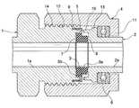
管継手は、互いに連通する流体通路を有している管状の第1の継手部材(1)および管状の第2の継手部材(2)と、第1の継手部材(1)の右端面と第2の継手部材(2)の左端面との間に介在させられる円環状ガスケット(3)と、円環状ガスケット(3)を保持しかつ第1の継手部材(1)に保持されるリテーナ(5)とを備えており、第2の継手部材(2)側から第1の継手部材(1)にねじはめられたナット(4)により、第2の継手部材(2)が第1の継手部材(1)に固定されている。各継手部材(1)(2)の突合わせ端面の半径方向には、円環状シール突起(7)(8)がそれぞれ形成され、同外周部には、環状の締過ぎ防止突起(9)(10)がそれぞれ形成されている。 The pipe joint includes a tubular first joint member (1) and a tubular second joint member (2) having fluid passages communicating with each other, and the right end surface and the first of the first joint member (1). A retainer (5) that holds an annular gasket (3) interposed between the left end surface of the joint member (2) of 2 and the annular gasket (3) and is held by the first joint member (1). ), And the second joint member (2) is the first joint member by the nut (4) screwed from the second joint member (2) side to the first joint member (1). It is fixed to (1). An annular seal projections (7) and (8) are formed in the radial direction of the butt end faces of the joint members (1) and (2), and an annular overtightening prevention projection (9) (9) is formed on the outer peripheral portion thereof. 10) are formed respectively.
ガスケット(3)の両端面は、軸方向に対して直角な平坦面とされている。ガスケット(3)の外周面には、外向きフランジよりなる抜止め部(3b)が設けられている。 Both end faces of the gasket (3) are flat surfaces perpendicular to the axial direction. On the outer peripheral surface of the gasket (3), a retaining portion (3b) made of an outward flange is provided.
両継手部材(1)(2)およびガスケット(3)は、SUS316L製である。 Both joint members (1) and (2) and gasket (3) are made of SUS316L.
ナット(4)の右端部には内向きフランジ(11)が形成されており、このフランジ(11)の部分が第2の継手部材(2)の周囲にはめられている。ナット(4)の左端部の内周にはめねじ(12)が形成されており、これが第1の継手部材(1)の右側に形成されたおねじ(14)にねじはめられている。第2の継手部材(2)の左端部外周には外向きフランジ(13)が形成されており、これとナット(4)の内向きフランジ(11)との間に共回り防止用のスラスト玉軸受(6)が介在させられている。 An inward flange (11) is formed at the right end portion of the nut (4), and the portion of the flange (11) is fitted around the second joint member (2). A female screw (12) is formed on the inner circumference of the left end portion of the nut (4), and this is screwed into a male screw (14) formed on the right side of the first joint member (1). An outward flange (13) is formed on the outer periphery of the left end of the second joint member (2), and a thrust ball for preventing co-rotation between this and the inward flange (11) of the nut (4). A bearing (6) is interposed.
各締過ぎ防止用環状突起(9)(10)は、円環状シール突起(7)(8)よりも左右方向ガスケット(3)側に突出させられており、適正な締付けよりもさらに締付けようとしたさいに、リテーナ(5)をその両面から押圧するようになされている。 The annular protrusions (9) and (10) for preventing overtightening are projected toward the gasket (3) in the left-right direction from the annular seal protrusions (7) and (8), so that the tightening is more than proper tightening. At that time, the retainer (5) is pressed from both sides thereof.
手で締め付けた状態からスパナ等によりさらにナット(4)を締付けていくと、締過ぎ防止突起(9)(10)とリテーナ(5)との間の隙間が0となり、締付けに対する抵抗力が非常に大きくなり、締過ぎが防止される。 When the nut (4) is further tightened with a spanner or the like from the state of being tightened by hand, the gap between the overtightening prevention protrusions (9) and (10) and the retainer (5) becomes 0, and the resistance to tightening becomes extremely high. It becomes large and overtightening is prevented.
第1の継手部材(1)の内周(1a)、第2の継手部材(2)の内周(2a)およびガスケットの内周(3a)が流体通路を形成している。 The inner circumference (1a) of the first joint member (1), the inner circumference (2a) of the second joint member (2), and the inner circumference (3a) of the gasket form a fluid passage.
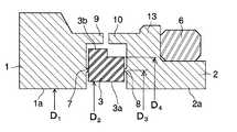
第1および第2の継手部材の内径をD1、ガスケットの内径をD2、シール突起の直径をD3およびガスケットの外径をD4としたときの係数F=(D32−D12)/(D42−D22)が、0.4以下であることが好ましい。さらに係数Fが0.3以下であることがより好ましい。Coefficient F = (D32- D1 ) when the inner diameter of the first and second joint members is D1 , the inner diameter of the gasket is D2 , the diameter of the seal protrusion is D3, and the outer diameter of the gasket is
ここで、D3は、円環状シール突起(7)(8)の最突出部分の中央点を結ぶ直径であり、D4は、抜け止め部(3b)を含まない円環状ガスケット(3)の外径である。Here, D3 is the diameter connecting the center points of the most protruding portions of the annular seal protrusions (7) and (8), and D4 is the diameter of the annular gasket (3) that does not include the retaining portion (3b). The outer diameter.
係数Fが0.4以下になるとガスケットの変形が抑えられる傾向が出てくる。係数Fが0.3以下となるとガスケットの変形が低く抑えられるのでさらに好ましい。 When the coefficient F is 0.4 or less, the deformation of the gasket tends to be suppressed. When the coefficient F is 0.3 or less, the deformation of the gasket can be suppressed to a low level, which is more preferable.
図2は、管継手に内圧を加えた時の応力・歪をシミュレーションするためのモデルの概略図である。第1の管継手(1)と第2の管継手(2)に挟まれたガスケット(3)を基本構成として、内周(1a)(2a)の内径をD1、内周(3a)の内径をD2、円環状シール突起(7)(8)の直径をD3およびガスケット(3)の外径であって、抜止め部(3b)でない外径をD4として解析を行った。
(試験例1)
部材の材料をステンレス鋼とし、有限要素解析を行った。下表[表1]にD1〜D4の値、その値の時の係数Fおよびガスケット(3)が外れ始めるときの圧力Pを示し、そのFとPとの関係を示すグラフを図3に示す。なお、破線は近似直線である。FIG. 2 is a schematic view of a model for simulating stress / strain when an internal pressure is applied to a pipe joint. Based on the basic configuration of the gasket (3) sandwiched between the first pipe joint (1) and the second pipe joint (2), the inner diameters of the inner circumferences (1a) and (2a) are D1 and the inner circumference (3a). inner diameterD 2, a outer diameter of the annular seal projection (7)D 3 and gasket diameter (8) (3), an outer diameter not retained portion (3b) was analyzed asD 4.
(Test Example 1)
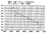
The material of the member was stainless steel, and finite element analysis was performed. The table below [Table 1] showsthe values of D 1 to D4 , the coefficient F at that value, and the pressure P when the gasket (3) starts to come off, and a graph showing the relationship between F and P is shown in FIG. Shown in. The broken line is an approximate straight line.

(試験例2)
次に、部材の材料をステンレスとし、有限要素解析を行った。下表[表2]にD1〜D4の値、その値の時の係数Fおよびガスケット(3)−継手部材(1)(2)間の密着性がなくなるときの圧力Pを示し、そのFとPとの関係を示すグラフを図4に示す。なお、破線は近似直線である。
(Test Example 2)
Next, the material of the member was stainless steel, and a finite element analysis was performed. The table below [Table 2] showsthe values of D 1 to D4 , the coefficient F at that value, and the pressure P when the adhesion between the gaskets (3) and the joint members (1) and (2) is lost. A graph showing the relationship between F and P is shown in FIG. The broken line is an approximate straight line.
(試験例3)
次に、試験例2と同じ条件で有限要素解析を行った。下表[表3]にD1〜D4の値、その値の時の係数Fおよびガスケット(3)−継手部材(1)(2)間の密着性がなくなるときのガスケットの内径変位、ガスケットの外径変位およびガスケットの円環状シール突起(7)(8)の変位を示し、そのFと変位との関係を示すグラフを図5に示す。なお、変位の単位はmmである。
(Test Example 3)
Next, a finite element analysis was performed under the same conditions as in Test Example 2. In the table below [Table 3],the values of D 1 to D4 , the coefficient F at that value, the inner diameter displacement of the gasket when the adhesion between the gasket (3) and the joint members (1) and (2) is lost, and the gasket. The displacement of the outer diameter of the gasket and the displacement of the annular seal protrusions (7) and (8) of the gasket are shown, and a graph showing the relationship between F and the displacement is shown in FIG. The unit of displacement is mm.
変位は小さければ小さいほど耐圧性能を高めるには有利であることから、変位が減少に転じる0.4以下の係数Fであることが好ましい。さらに、変位が最も小さく一定に保たれる0.3以下の係数Fであることがより好ましい。 Since the smaller the displacement, the more advantageous it is to improve the pressure resistance performance, it is preferable that the coefficient F is 0.4 or less, which causes the displacement to decrease. Further, it is more preferable that the coefficient F is 0.3 or less and the displacement is the smallest and is kept constant.
超高圧仕様の配管の管継手に関し、コンパクトな最適形状の管継手を提供することができる。 With respect to pipe joints for ultra-high pressure specifications, it is possible to provide a compact and optimum shape pipe joint.
1:第1の継手部材
2:第2の継手部材
3:ガスケット
7:円環状シール突起
8:円環状シール突起1: First joint member 2: Second joint member 3: Gasket 7: Circular seal protrusion 8: Circular seal protrusion
Claims (2)
Translated fromJapanese前記第1および第2の継手部材の突合せ端面間に介在させられるガスケットを備え、
前記第1および第2の継手部材の突合せ端面には環状のシール突起が形成されている管継手において、
前記第1および第2の継手部材の内径をD1、前記ガスケットの内径をD2、前記シール突起の直径をD3、前記ガスケットの外径をD4としたときに、
下記式(1)で規定される係数Fが0.4以下であることを特徴とする管継手。
式(1):F=(D32−D12)/(D42−D22)A first and second joint member having fluid passages communicating with each other,
A gasket provided between the butt end faces of the first and second joint members is provided.
In a pipe joint in which an annular seal protrusion is formed on the butt end face of the first and second joint members.
When the inner diameter of the first and second joint members is D1 , the inner diameter of the gasket is D2 , the diameter of the seal protrusion is D3 , and the outer diameter of the gasket is D4 .
A pipe joint characterized in that the coefficient F defined by the following formula (1) is 0.4 or less.
Equation (1): F = (D32- D12 ) / (D42- D22 )
前記第1および第2の継手部材の突合せ端面間に介在させられるガスケットを備え、 A gasket provided between the butt end faces of the first and second joint members is provided.
前記第1および第2の継手部材の突合せ端面には環状のシール突起が形成されている管継手の設計方法であって、 A method for designing a pipe joint in which an annular seal protrusion is formed on the butt end faces of the first and second joint members.
前記第1および第2の継手部材の内径をD The inner diameter of the first and second joint members is D.11、前記ガスケットの内径をD, The inner diameter of the gasket is D22、前記シール突起の直径をD, The diameter of the seal protrusion is D33、前記ガスケットの外径をD, The outer diameter of the gasket is D44としたときに、When
下記式(1)で規定される係数Fが0.4以下であることを特徴とする管継手の設計方法。A method for designing a pipe joint, characterized in that the coefficient F defined by the following formula (1) is 0.4 or less.
式(1):F=(DEquation (1): F = (D3322−D-D1122)/(D) / (D4422−D-D2222))
Priority Applications (8)
| Application Number | Priority Date | Filing Date | Title |
|---|---|---|---|
| JP2016150488AJP6955739B2 (en) | 2016-07-29 | 2016-07-29 | Pipe fitting |
| US16/321,166US20190162337A1 (en) | 2016-07-29 | 2017-07-25 | Pipe joint |
| KR1020197001348AKR102208902B1 (en) | 2016-07-29 | 2017-07-25 | Pipe joint |
| PCT/JP2017/026838WO2018021294A1 (en) | 2016-07-29 | 2017-07-25 | Pipe joint |
| SG11201900599RASG11201900599RA (en) | 2016-07-29 | 2017-07-25 | Pipe joint |
| CN201780045130.9ACN109477600B (en) | 2016-07-29 | 2017-07-25 | Pipe joint |
| TW106125215ATWI718324B (en) | 2016-07-29 | 2017-07-27 | Pipe joint |
| IL264388AIL264388A (en) | 2016-07-29 | 2019-01-21 | Pipe joint |
Applications Claiming Priority (1)
| Application Number | Priority Date | Filing Date | Title |
|---|---|---|---|
| JP2016150488AJP6955739B2 (en) | 2016-07-29 | 2016-07-29 | Pipe fitting |
Publications (2)
| Publication Number | Publication Date |
|---|---|
| JP2018017381A JP2018017381A (en) | 2018-02-01 |
| JP6955739B2true JP6955739B2 (en) | 2021-10-27 |
Family
ID=61016375
Family Applications (1)
| Application Number | Title | Priority Date | Filing Date |
|---|---|---|---|
| JP2016150488AActiveJP6955739B2 (en) | 2016-07-29 | 2016-07-29 | Pipe fitting |
Country Status (8)
| Country | Link |
|---|---|
| US (1) | US20190162337A1 (en) |
| JP (1) | JP6955739B2 (en) |
| KR (1) | KR102208902B1 (en) |
| CN (1) | CN109477600B (en) |
| IL (1) | IL264388A (en) |
| SG (1) | SG11201900599RA (en) |
| TW (1) | TWI718324B (en) |
| WO (1) | WO2018021294A1 (en) |
Families Citing this family (7)
| Publication number | Priority date | Publication date | Assignee | Title |
|---|---|---|---|---|
| WO2019058737A1 (en) | 2017-09-22 | 2019-03-28 | 住友金属鉱山株式会社 | Cesium tungsten oxide film and method for manufacturing same |
| US10711926B2 (en)* | 2017-10-30 | 2020-07-14 | CNN Industrial America LLC | Sealing assembly with retention sleeve for fluid conduit connector |
| CN108662315A (en)* | 2018-07-27 | 2018-10-16 | 王晴 | A kind of feed pipe of the construction site convenient for connection |
| DE102019209672A1 (en)* | 2019-07-02 | 2021-01-07 | Zf Friedrichshafen Ag | Pipeline, drive train unit with such a pipeline, as well as assembly methods |
| CN110374757A (en)* | 2019-07-20 | 2019-10-25 | 徐海燕 | A kind of connection structure of valve mechanism cover and breather adapter |
| JP7333954B2 (en)* | 2019-10-29 | 2023-08-28 | 株式会社フジキン | Joint structure and joint structure assembly method |
| US12234776B2 (en) | 2023-05-25 | 2025-02-25 | Pratt & Whitney Canada Corp. | Double seal arrangement |
Family Cites Families (12)
| Publication number | Priority date | Publication date | Assignee | Title |
|---|---|---|---|---|
| FR2641599B1 (en)* | 1989-01-12 | 1991-04-26 | Desbiolles Christian | CONNECTION DEVICE WITH SEAL FOR TUBULAR ELEMENTS |
| CA2176652C (en)* | 1995-08-09 | 2007-07-17 | Tadahiro Ohmi | Pipe joint |
| JP3928092B2 (en)* | 1996-10-15 | 2007-06-13 | 忠弘 大見 | Fluid coupling |
| JP3876351B2 (en)* | 1997-06-18 | 2007-01-31 | 忠弘 大見 | Pipe fitting |
| JP2003343726A (en)* | 2002-05-24 | 2003-12-03 | Sanko Kogyo Kk | Gasket |
| WO2008100540A1 (en)* | 2007-02-12 | 2008-08-21 | Michael Doyle | Ring seal and retainer assembly |
| JP2009115160A (en)* | 2007-11-05 | 2009-05-28 | Sanko Kogyo Kk | Gasket and pipe coupling using the same |
| US20090258143A1 (en)* | 2008-04-11 | 2009-10-15 | Peck John D | Reagent dispensing apparatus and delivery method |
| KR101230671B1 (en)* | 2008-04-22 | 2013-02-07 | 가부시키가이샤 후지킨 | Fluid coupling and retainer for fluid coupling |
| JP5608463B2 (en)* | 2010-08-02 | 2014-10-15 | 株式会社フジキン | Fluid coupling |
| JP5988822B2 (en)* | 2012-10-19 | 2016-09-07 | 株式会社フジキン | Pipe fitting |
| WO2015130427A1 (en)* | 2014-02-27 | 2015-09-03 | Sundew Technologies, Llc | Face sealed fittings |
- 2016
- 2016-07-29JPJP2016150488Apatent/JP6955739B2/enactiveActive
- 2017
- 2017-07-25WOPCT/JP2017/026838patent/WO2018021294A1/ennot_activeCeased
- 2017-07-25KRKR1020197001348Apatent/KR102208902B1/enactiveActive
- 2017-07-25USUS16/321,166patent/US20190162337A1/ennot_activeAbandoned
- 2017-07-25CNCN201780045130.9Apatent/CN109477600B/ennot_activeExpired - Fee Related
- 2017-07-25SGSG11201900599RApatent/SG11201900599RA/enunknown
- 2017-07-27TWTW106125215Apatent/TWI718324B/enactive
- 2019
- 2019-01-21ILIL264388Apatent/IL264388A/enunknown
Also Published As
| Publication number | Publication date |
|---|---|
| JP2018017381A (en) | 2018-02-01 |
| US20190162337A1 (en) | 2019-05-30 |
| WO2018021294A1 (en) | 2018-02-01 |
| SG11201900599RA (en) | 2019-04-29 |
| CN109477600B (en) | 2020-11-10 |
| KR102208902B1 (en) | 2021-01-28 |
| TWI718324B (en) | 2021-02-11 |
| CN109477600A (en) | 2019-03-15 |
| KR20190018509A (en) | 2019-02-22 |
| TW201809523A (en) | 2018-03-16 |
| IL264388A (en) | 2019-05-30 |
Similar Documents
| Publication | Publication Date | Title |
|---|---|---|
| JP6955739B2 (en) | Pipe fitting | |
| JP6699992B2 (en) | Gasket for fluid coupling and fluid coupling | |
| JP5416769B2 (en) | Extrusion prevention gasket face seal | |
| US20080036209A1 (en) | Assembly including a spring-energized polymeric seal | |
| US11098827B2 (en) | Tubular structure and manufacturing method therefor | |
| US3917324A (en) | Pipe joint | |
| WO2018079633A1 (en) | Seal structure, sealing method, and coupling equipped with said seal structure | |
| US20130134707A1 (en) | Pipe coupling for the fluid-tight attachment of components in an air conditioning system | |
| WO2016059755A1 (en) | Joint structure for vacuum-heat-insulated double tube for low temperature fluid | |
| US9394996B2 (en) | Sealing device | |
| JP5087555B2 (en) | Fluid coupling | |
| WO2016072087A1 (en) | Gasket | |
| KR101889960B1 (en) | Connecting structure of refrigerant pipe | |
| JPH08184393A (en) | Pipe fitting | |
| EP2472159A1 (en) | Flange seal | |
| WO2018079632A1 (en) | Seal structure, sealing method, and coupling equipped with said seal structure | |
| JP2020180695A (en) | Pipe joint | |
| JP6300067B2 (en) | Pipe fitting | |
| JP2019178689A (en) | Pipe joint | |
| JP2020180694A (en) | Pipe joint | |
| JP3161105U (en) | Piping connection structure | |
| JP2016136049A (en) | Pipe joint | |
| KR20170124722A (en) | Spiral wound gasket for high temperature and high pressure fluid | |
| JP2007146880A (en) | Tube fitting | |
| JP2001254878A (en) | Joint for bellows pipes |
Legal Events
| Date | Code | Title | Description |
|---|---|---|---|
| A521 | Request for written amendment filed | Free format text:JAPANESE INTERMEDIATE CODE: A523 Effective date:20161024 | |
| A521 | Request for written amendment filed | Free format text:JAPANESE INTERMEDIATE CODE: A821 Effective date:20161024 | |
| A621 | Written request for application examination | Free format text:JAPANESE INTERMEDIATE CODE: A621 Effective date:20190722 | |
| A131 | Notification of reasons for refusal | Free format text:JAPANESE INTERMEDIATE CODE: A131 Effective date:20200602 | |
| A601 | Written request for extension of time | Free format text:JAPANESE INTERMEDIATE CODE: A601 Effective date:20200716 | |
| A131 | Notification of reasons for refusal | Free format text:JAPANESE INTERMEDIATE CODE: A131 Effective date:20210224 | |
| A521 | Request for written amendment filed | Free format text:JAPANESE INTERMEDIATE CODE: A523 Effective date:20210331 | |
| TRDD | Decision of grant or rejection written | ||
| A01 | Written decision to grant a patent or to grant a registration (utility model) | Free format text:JAPANESE INTERMEDIATE CODE: A01 Effective date:20210831 | |
| A61 | First payment of annual fees (during grant procedure) | Free format text:JAPANESE INTERMEDIATE CODE: A61 Effective date:20210927 | |
| R150 | Certificate of patent or registration of utility model | Ref document number:6955739 Country of ref document:JP Free format text:JAPANESE INTERMEDIATE CODE: R150 | |
| R250 | Receipt of annual fees | Free format text:JAPANESE INTERMEDIATE CODE: R250 | |
| R250 | Receipt of annual fees | Free format text:JAPANESE INTERMEDIATE CODE: R250 |