JP6949231B2 - Air conditioning control device, air conditioning control system and air conditioning control method - Google Patents
Air conditioning control device, air conditioning control system and air conditioning control methodDownload PDFInfo
- Publication number
- JP6949231B2 JP6949231B2JP2020530812AJP2020530812AJP6949231B2JP 6949231 B2JP6949231 B2JP 6949231B2JP 2020530812 AJP2020530812 AJP 2020530812AJP 2020530812 AJP2020530812 AJP 2020530812AJP 6949231 B2JP6949231 B2JP 6949231B2
- Authority
- JP
- Japan
- Prior art keywords
- request
- range
- air
- user
- air conditioning
- Prior art date
- Legal status (The legal status is an assumption and is not a legal conclusion. Google has not performed a legal analysis and makes no representation as to the accuracy of the status listed.)
- Expired - Fee Related
Links
Images


Classifications
- F—MECHANICAL ENGINEERING; LIGHTING; HEATING; WEAPONS; BLASTING
- F24—HEATING; RANGES; VENTILATING
- F24F—AIR-CONDITIONING; AIR-HUMIDIFICATION; VENTILATION; USE OF AIR CURRENTS FOR SCREENING
- F24F11/00—Control or safety arrangements
- F24F11/50—Control or safety arrangements characterised by user interfaces or communication
Landscapes
- Engineering & Computer Science (AREA)
- Human Computer Interaction (AREA)
- Chemical & Material Sciences (AREA)
- Combustion & Propulsion (AREA)
- Mechanical Engineering (AREA)
- General Engineering & Computer Science (AREA)
- Air Conditioning Control Device (AREA)
Description
Translated fromJapanese本発明は、空調制御装置、空調制御システム及び空調制御方法に関する。 The present invention relates to an air conditioning control device, an air conditioning control system, and an air conditioning control method.
住宅及びオフィスに代表される施設では、通常、複数のユーザが存在する空間における空気を調和するための空調システムが形成される。この種の空調システムでは、空気の温度及び湿度に代表される状態の目標値が定められ、その目標値が空気の状態の計測値に等しくなるように空調が行われる。 In facilities represented by houses and offices, an air conditioning system for harmonizing air in a space where a plurality of users exist is usually formed. In this type of air conditioning system, a target value of a state represented by the temperature and humidity of air is set, and air conditioning is performed so that the target value becomes equal to the measured value of the air state.
ここで、複数のユーザのうちの一部、或いは管理者が目標値を定める場合には、複数のユーザにとって快適な目標値が定まらないことがある。また、各ユーザが目標値を定めると、各ユーザの希望する目標値が異なるため最終的な目標値が定まらないことが多い。そこで、各ユーザの要望をある程度考慮して目標値を定める技術が提案されている(例えば、特許文献1を参照)。 Here, when a part of a plurality of users or an administrator sets a target value, a comfortable target value for the plurality of users may not be determined. Further, when each user sets a target value, the final target value is often not determined because the target value desired by each user is different. Therefore, a technique for setting a target value in consideration of each user's request to some extent has been proposed (see, for example, Patent Document 1).
特許文献1には、対象空間内の複数の利用者それぞれの嗜好を合理的に調整する環境調整装置について記載されている。この装置は、対象空間の環境条件について複数の利用者それぞれの嗜好範囲を取得し、取得した嗜好範囲に基づく重みを設定値の候補に付与することで、最終的な設定値を決定する。この装置によれば、複数の利用者の嗜好範囲を加味して環境を調整することができる。
特許文献1に記載の装置は、設定値の候補が複数ある場合に、各利用者の希望する試行範囲との距離の合算値が最小となるような候補を設定値として決定していた。しかしながら、ユーザが次善として要望する嗜好範囲があれば、上述のように決定された設定値は、必ずしもユーザの要望に沿ったものになるとは限らない。このため、一部のユーザにとって不快となる空調が行われるおそれがあった。したがって、複数のユーザの快適性を向上させる余地があった。 In the apparatus described in
本発明は、上記の事情に鑑みてなされたものであり、複数のユーザの快適性を向上させることを目的とする。 The present invention has been made in view of the above circumstances, and an object of the present invention is to improve the comfort of a plurality of users.
上記目的を達成するため、本発明の空調制御装置は、空調の対象となる空間における空気の状態の範囲について、第1ユーザの第1要望を示す第1信号と第2ユーザの第2要望を示す第2信号とを受信する受信手段と、現在における第1要望及び第2要望の少なくとも一方に関する条件が成立したときに、制御信号を送信して、空気を調和する空調装置を制御することにより、現在又は過去における第1要望の範囲と過去における第2要望の範囲とが重複する目標範囲内に空気の状態を収める制御手段と、を備え、第2要望は、第2ユーザに関して予め定められた2以上の範囲からいずれかの範囲を選択する要望であり、過去における第2要望の範囲は、2以上の範囲のうち、過去に選択された割合が最も大きい範囲である。In order to achieve the above object, the air conditioning control device of the present invention obtains a first signal indicating the first request of the first user and a second request of the second user regarding the range of the air condition in the space to be air-conditioned. By transmitting a control signal to control the air conditioner that harmonizes the air when the receiving means for receiving the indicated second signal and at least one of the current first request and the second request are satisfied. A control means for keeping the air condition within a target range in which the range of the first request in the present or the past and the range of the second request in the past overlap is provided, and the second request is predetermined for the second user. It is a request to select any range from two or more ranges, and the range of the second request in the past is the range in which the ratio selected in the past is the largest among the two or more ranges .
本発明によれば、制御手段が、現在における第1要望及び第2要望の少なくとも一方に関する条件が成立したときに、現在又は過去における第1要望の範囲と過去における第2要望の範囲とが重複する目標範囲内に空気の状態を収める。ユーザの過去の要望は、ユーザの次善としての要望に等しいものと考えられる。このため、条件が成立したときには、ユーザが次善として要望する範囲を目標として、空調装置が制御される。これにより、複数のユーザの快適性を向上させることができる。 According to the present invention, when the control means satisfies the conditions relating to at least one of the current first request and the second request, the range of the first request in the present or the past and the range of the second request in the past overlap. Keep the air condition within the target range. The user's past demands are considered to be equal to the user's second best demands. Therefore, when the condition is satisfied, the air conditioner is controlled with the target of the range requested by the user as the next best. Thereby, the comfort of a plurality of users can be improved.
以下、本発明の実施の形態に係る空調制御装置10について、図面を参照しつつ詳細に説明する。 Hereinafter, the air
実施の形態.
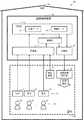
本実施の形態に係る空調制御装置10は、複数のユーザからの要望を受け付けて、受け付けた要望に沿った空調を実現する装置である。詳細には、空調制御装置10は、図1に示されるように、ユーザ2a,2b,2cが端末31,32,33に入力した要望を示す信号を受信し、受信した要望に基づいて、空調空気を吹き出す空調装置40を制御する。以下では、ユーザ2a,2b,2cを総称してユーザ20と適宜表記し、端末31,32,33を総称して端末30と適宜表記する。Embodiment.
The air-
空調制御装置10は、端末30及び空調装置40とともに、空調制御システム100を構成する。空調制御システム100は、建物110において空調対象となる空間200における空気の状態を調和するためのシステムである。建物110は、住宅又はオフィスに代表される施設である。空間200は、建物110の内部に形成される部屋である。空調制御システム100は、空調制御装置10、端末30及び空調装置40の他に、ユーザが空間200内に在室しているか否かを検出する検出装置50を有する。 The air
空調制御装置10、端末30、空調装置40及び検出装置50は、通信路を介して互いに信号を送受信することにより通信する。通信路は、例えば、建物110内に形成されたLAN(Local Area Network)又はインターネットに代表される広域ネットワークである。 The air-
ユーザ20は、空調制御システム100の利用者であって、例えば、住宅である建物110の住人、又は、オフィスである建物110で勤務する者である。ユーザ20は、各自の端末30を携帯し、空間200に在室しているときに、空調に関する要望を自身の端末30に入力する。 The
端末30は、例えば、スマートホン又はタブレット型の端末である。端末30は、空調制御装置10に対するユーザインタフェースとして機能する。ユーザ20は、端末30を操作して、空間200における空気の状態の範囲について予め定められた複数の範囲からいずれか1つの範囲を選択して入力する。空気の状態は、温度及び湿度を含む。 The
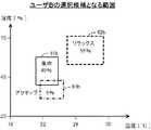
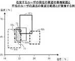
図2には、ユーザ2aの選択する候補となる要望の範囲が例示されている。図2中の範囲61aは、「集中」というラベルが付された範囲であって、範囲62aは、「リラックス」というラベルが付された範囲であって、範囲63aは、「アクティブ」というラベルが付された範囲である。ユーザ2aが、「集中」の空調モード、「リラックス」の空調モード、及び「アクティブ」の空調モード、の3つからいずれか1つのモードを選択すると、このモードに対応する範囲が、ユーザ2aの要望する範囲として端末31に入力されることとなる。 FIG. 2 illustrates a range of requests that can be selected by the
図2と同様に、図3には、ユーザ2bの選択する候補となる要望の範囲が例示されており、図4には、ユーザ2cの選択する候補となる要望の範囲が例示されている。図3中の範囲61bは、「集中」の空調モードに対応する範囲であって、範囲62bは、「リラックス」の空調モードに対応する範囲であって、範囲63bは、「アクティブ」の空調モードに対応する範囲である。ユーザ2bが、3つの空調モードからいずれか1つのモードを選択すると、このモードに対応する範囲が、ユーザ2bの要望する範囲として端末32に入力される。また、図4中の範囲61cは、「集中」の空調モードに対応する範囲であって、範囲62cは、「リラックス」の空調モードに対応する範囲であって、範囲63cは、「アクティブ」の空調モードに対応する範囲である。ユーザ2cが、3つの空調モードからいずれか1つのモードを選択すると、このモードに対応する範囲が、ユーザ2cの要望する範囲として端末33に入力される。 Similar to FIG. 2, FIG. 3 illustrates a range of requests that can be selected by user 2b, and FIG. 4 illustrates a range of requests that can be selected by
空調装置40は、空間200に空調空気を吹き出すことで空間200における空気を調和する室内機である。この空調装置40は、冷媒配管を介して空調装置としての室外機に接続され、この室外機との間で冷媒を循環させることで、温度及び湿度が調整された空調空気を生成して、空間200に供給する。空調装置40が生成する空調空気の状態は、空調制御装置10から送信される制御信号に従う。 The
検出装置50は、オフィスである建物110内の空間200の入り口に設けられた入室カードキーの読み取り端末と接続された入退室管理システムである。検出装置50は、空間200内にいるユーザ20と、空間200外にいるユーザ20と、を識別して、各ユーザ20が在室するか不在であるかを示す検出信号を空調制御装置10へ送信する。 The
空調制御装置10は、端末30及び検出装置50から信号を受信する受信部11と、種々のデータを記憶する記憶部12と、ユーザの要望を調停して空調の目標範囲を決定する調停部13と、空調装置40に制御信号を送信することにより空調装置40を制御する制御部14と、を有する。 The air
受信部11は、端末31〜33それぞれからユーザ2a,2b,2cの要望を示す信号を受信し、検出装置50から検出結果を示す検出信号を受信する。詳細には、受信部11は、ユーザ2aの第1要望を示す第1信号を受信し、ユーザ2bの第2要望を示す第2信号を受信し、ユーザ2cの第3要望を示す第3信号を受信する。そして、受信部11は、受信した信号により示される情報を調停部13に通知する。また、受信部11は、ユーザ20の要望を記憶部12に通知する。受信部11は、請求項の受信手段として機能する。 The receiving unit 11 receives signals indicating the requests of the
記憶部12は、ユーザ20の要望に関する要望データ121と、空調装置40を制御するための制御データ122と、を記憶して管理するデータベース管理システムである。記憶部12は、受信部11によって受信された信号により示される要望により要望データ121を更新する。制御データ122は、予め記憶部12に格納されていてもよいし、ユーザ20によって変更されてもよい。 The
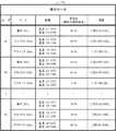
要望データ121は、各ユーザ20が過去に選択した範囲の割合を示すデータである。図5には、要望データ121の一例が示されている。この要望データ121は、ユーザ20の識別子と、このユーザ20の選択候補となるモードと、このモードに対応する空気の状態の範囲と、このモードが過去に選択された割合を示す要望度と、このモードが過去に選択された日時を示す履歴と、を関連付けるテーブル形式のデータである。 The
図5中、ユーザ2a,2b,2cの識別子はそれぞれ、「A」,「B」,「C」とされている。また、「モード」として、空調モードのラベル、及びそのモードに対応する範囲の識別子が示されている。例えば、ユーザ「A」についてのモード「集中 [61a]」は、図2の範囲61aに対応する。同様に、図5の「モード」において、そのモードに対応する識別子は、図2〜4に示される範囲の符号に等しいものとされている。「範囲」は、温度の範囲と湿度の範囲とを示している。 In FIG. 5, the identifiers of the
「要望度」は、ユーザ20が3つのモードから対応するモードを過去に選択した割合を示す。例えば、ユーザ「A」に関して、過去におけるモードの選択のうち、60%を示す選択が、「集中」という空調モードの選択であったことが示されている。ユーザ20が過去に選択したモードは、将来においてもユーザ20が選択する可能性がある。特に、要望度が高い場合には、今後においてもユーザ20が要望する確率が高いといえるため、ユーザ20が現時点において選択していないモードであっても、このモードは、当該ユーザ20が次善として希望するものとして扱うことができる。ここで、過去に選択した割合は、最新の選択を含んでもよいし、含まなくてもよい。また、割合を算出するための過去の選択は、過去の全期間にわたる選択であってもよいし、予め定められた一定期間における選択であってもよい。一定期間は、例えば、現在日時までの1週間又は1か月間である。 The "request degree" indicates the ratio of the
「履歴」は、過去におけるモードの選択履歴を示す。記憶部12は、この「履歴」に基づいて「要望度」を随時更新する。 "History" indicates the mode selection history in the past. The
図1に戻り、調停部13は、受信部11によって受信された信号により示される要望と、記憶部12に記憶される要望データ121と、に基づいて、複数のユーザ20による要望を調停して、空調制御の目標範囲を決定する。調停部13による調停の詳細については後述する。 Returning to FIG. 1, the
制御部14は、制御信号を送信して空調装置40を制御することにより、調停部13によって決定された目標範囲内に空気の状態を収める。制御部14は、記憶部12に記憶される制御データ122に基づいて、目標範囲に含まれる制御目標値を決定し、この制御目標値を示す制御信号を空調装置40に送信する。制御部14は、請求項の制御手段として機能する。 By transmitting a control signal to control the
ここで、空調制御装置10が取得した要望に対する制御の持続について、図6を用いて説明する。図6には、ユーザA,B,Cの要望の入力タイミングと、制御の持続時間と、の関係が示されている。図6において、ユーザAによる要望A1、ユーザBによる要望B1,B2、及びユーザCによる要望C1それぞれの入力タイミングが、矢印で示されている。また、制御の内容は、周期的な時刻T1,T2,T3,T4,T5に更新される。時刻T1〜T2の時間間隔は、例えば10秒間、1分間又は10分間である。 Here, the continuation of control for the request acquired by the air
要望A1が入力された直後からこの要望A1に対する制御が開始されるのではなく、要望A1が入力された後の最初の制御の更新タイミングである時刻T2に、要望A1に対する制御が開始する。そして、要望A1に対する制御は、更新周期の2回分に相当する時間T10にわたって継続される。時刻T2から時刻T3までの期間においては、要望A1に対する制御が実行されるため、要望A1は現在におけるユーザAの要望といえる。 The control for the request A1 is not started immediately after the request A1 is input, but the control for the request A1 is started at the time T2, which is the update timing of the first control after the request A1 is input. Then, the control for the request A1 is continued for a time T10 corresponding to two update cycles. Since the control for the request A1 is executed in the period from the time T2 to the time T3, the request A1 can be said to be the request of the user A at present.
時刻T2と時刻T3との間に要望B1,C1が入力される。この要望B1,C1に対する制御は、時刻T3から開始される。ただし、時刻T3から時刻T4までは、要望A1に対する制御も合わせて実行されるため、要望A1,B1,C1に対する制御が実行されることとなる。時刻T3から時刻T4までの期間においては、要望A1,B1,C1が現在におけるユーザA,B,Cの要望といえる。 Requests B1 and C1 are input between the time T2 and the time T3. The control for the requests B1 and C1 starts from the time T3. However, since the control for the request A1 is also executed from the time T3 to the time T4, the control for the requests A1, B1, and C1 is executed. In the period from time T3 to time T4, requests A1, B1 and C1 can be said to be the current requests of users A, B and C.
時刻T3と時刻T4との間に要望B2が入力される。この要望B2は、要望B1とは異なるモードを選択する要望であってもよいし、要望B1と同じモードを選択することでこのモードに応じた制御の持続時間を延長する要望であってもよい。要望B2に対する制御は、時刻T4から開始される。また、要望B2が入力されることで要望B1に対する制御は不要となるため時刻T4からは実行されない。さらに、要望A1に対する制御が時刻T4で終了するため、時刻T4からは、要望B2,C1に対する制御が実行されることとなる。時刻T4から時刻T5までの期間においては、要望B2,C1がユーザB,Cの現在における要望といえる。また、要望A1,B1は、ユーザA,Bの過去における要望といえる。 Request B2 is input between time T3 and time T4. The request B2 may be a request to select a mode different from the request B1, or may be a request to extend the duration of control according to this mode by selecting the same mode as the request B1. .. Control for request B2 starts at time T4. Further, since the request B2 is input, the control for the request B1 becomes unnecessary, so that the request B2 is not executed from the time T4. Further, since the control for the request A1 ends at the time T4, the control for the requests B2 and C1 is executed from the time T4. In the period from time T4 to time T5, requests B2 and C1 can be said to be the current requests of users B and C. Further, the requests A1 and B1 can be said to be the requests of the users A and B in the past.
以下では、ある時点において今後の制御を実行するための要望を現在における要望とし、要望に対する制御が既に終了した場合には、この要望を過去における要望として、説明する。なお、図6では、説明の理解を容易にするために持続時間T10をある程度短いものとしたが、持続時間T10の長さは、任意に変更してもよい。例えば、持続時間T10の長さを1時間、又は24時間としてもよい。 In the following, a request for executing future control at a certain point in time will be described as a current request, and when control for the request has already been completed, this request will be described as a past request. In FIG. 6, the duration T10 is set to be short to some extent in order to facilitate the understanding of the explanation, but the length of the duration T10 may be arbitrarily changed. For example, the length of the duration T10 may be 1 hour or 24 hours.
空調制御装置10は、そのハードウェア構成として、図7に示されるように、プロセッサ101と、主記憶部102と、補助記憶部103と、入力部104と、出力部105と、通信部106と、を有する。主記憶部102、補助記憶部103、入力部104、出力部105及び通信部106はいずれも、内部バス107を介してプロセッサ101に接続される。 As its hardware configuration, the air
プロセッサ101は、CPU(Central Processing Unit)を含む。プロセッサ101は、補助記憶部103に記憶されるプログラムP1を実行することにより、空調制御装置10の種々の機能を実現して、後述の処理を実行する。 The
主記憶部102は、RAM(Random Access Memory)を含む。主記憶部102には、補助記憶部103からプログラムP1がロードされる。そして、主記憶部102は、プロセッサ101の作業領域として用いられる。 The
補助記憶部103は、EEPROM(Electrically Erasable Programmable Read-Only Memory)及びHDD(Hard Disk Drive)に代表される不揮発性メモリを含む。補助記憶部103は、プログラムP1の他に、プロセッサ101の処理に用いられる種々のデータを記憶する。補助記憶部103は、プロセッサ101の指示に従って、プロセッサ101によって利用されるデータをプロセッサ101に供給し、プロセッサ101から供給されたデータを記憶する。 The
入力部104は、入力キー及びポインティングデバイスに代表される入力デバイスを含む。入力部104は、空調制御装置10のユーザによって入力された情報を取得して、取得した情報をプロセッサ101に通知する。 The
出力部105は、LCD(Liquid Crystal Display)及びスピーカに代表される出力デバイスを含む。出力部105は、プロセッサ101の指示に従って、種々の情報をユーザに提示する。 The
通信部106は、外部の装置と通信するためのネットワークインタフェース回路を含む。通信部106は、外部から信号を受信して、この信号により示されるデータをプロセッサ101へ出力する。また、通信部106は、プロセッサ101から出力されたデータを示す信号を外部の装置へ送信する。 The
図7に示されるハードウェア構成が協働することで、空調制御装置10は、図1に示される種々の機能を発揮する。詳細には、受信部11が、主として通信部106によって実現され、記憶部12が、主としてプロセッサ101及び補助記憶部103の協働により実現される。また、調停部13が、主としてプロセッサ101によって実現され、制御部14が、主としてプロセッサ101及び通信部106の協働によって実現される。
By cooperating with the hardware configurations shown in FIG. 7, the air
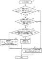
続いて、空調制御装置10によって実行される空調制御処理について、図8〜19を用いて説明する。図8に示される空調制御処理は、空調制御装置10に電源が投入されることで開始する。 Subsequently, the air conditioning control process executed by the air
空調制御処理において、空調制御装置10は、制御データ122を取得する(ステップS1)。具体的には、受信部11が、いずれかの端末30から、制御データ122を示す信号を受信して、記憶部12が制御データ122を更新する。記憶部12に格納された制御データ122は、後述の処理に用いられる。なお、いずれの端末30からも制御データ122を示す信号が受信されない場合には、ステップS1を省略してもよい。 In the air conditioning control process, the air
次に、空調制御装置10は、現在時刻がデータの取得タイミングであるか否かを判定する(ステップS2)。具体的には、調停部13が、ステップS2の判定が最後に肯定されてから予め定められた周期に等しい時間が経過したか否かを判定する。ステップS2のデータ取得タイミングは、図6に示された時刻T1〜T5に対応する。 Next, the air
現在時刻がデータの取得タイミングではないと判定した場合(ステップS2;No)、空調制御装置10は、ステップS1以降の処理を繰り返して、現在時刻がデータの取得タイミングとなるまで待機する。現在時刻がデータの取得タイミングであると判定した場合(ステップS2;Yes)、空調制御装置10は、検出装置50による在室のユーザ20及び不在のユーザ20の検出結果を示す検出信号を受信する(ステップS3)。 When it is determined that the current time is not the data acquisition timing (step S2; No), the air
次に、空調制御装置10は、空気の状態の範囲を選択するユーザ20の新たな要望があるか否かを判定する(ステップS4)。具体的には、調停部13が、前回のステップS4以降に、受信部11によって端末30からモードに対応する範囲についてユーザ20の要望を示す信号が受信されたか否かを判定する。 Next, the air
範囲を選択する要望がないと判定された場合(ステップS4;No)、空調制御装置10は、新たな制御を実行することなく、ステップS1以降の処理を繰り返す。一方、範囲を選択する要望があると判定された場合(ステップS4;Yes)、空調制御装置10は、要望を取得して要望データ121を更新する(ステップS5)。具体的には、調停部13が、ユーザ20の要望の内容を受信部11から取得する。また、記憶部12が、要望データ121の履歴を更新する。ここで、記憶部12は、過去の要望に基づいて要望度を履歴とともに更新する。ステップS5は、請求項の受信ステップに対応する。 When it is determined that there is no request to select the range (step S4; No), the air
次に、空調制御装置10は、予め定められた条件1が成立するか否かを判定する(ステップS6)。条件1は、在室する全ユーザ20の現在の要望の範囲が重複することである。図9には、条件1が成立する例が示されている。図9の例は、ユーザ2a,2bが在室しておりユーザ2cが在室していないときに、在室する全ユーザ2a,2bが要望する範囲63a,61bが重複している。詳細には、図9においてハッチングにより示されるように、範囲63a,61bが重複する重複範囲71が存在する。また、図10には、条件1が成立する他の例が示されている。図10の例は、ユーザ2a,2b,2cが在室しているときに、在室するユーザ2a,2b,2cが要望する範囲63a,61b,61cが重複している。詳細には、図10においてハッチングにより示されるように、範囲63a,61b,61cがすべて重複する重複範囲72が存在する。 Next, the air
また、図11には、条件1が成立しない例が示されている。図11の例は、ユーザ2a,2b,2cが在室しているときに、在室するユーザ2a,2bが要望する範囲63a,61bが図9と同様に重複しているが、在室するユーザ2cが要望する範囲62cは、範囲63a,61bと重複していない。さらに、図12には、条件1が成立しない他の例が示されている。図12の例は、ユーザ2a,2b,2cが在室しているときに、在室するユーザ2a,2b,2cが要望する範囲63a,62b,62cのいずれの組み合わせについても重複していない。 Further, FIG. 11 shows an example in which the
図8に戻り、ステップS6にて条件1が成立する場合(ステップS6;Yes)、空調制御装置10は、第1調停処理を実行する(ステップS7)。一方、条件1が成立しない場合(ステップS6;No)、空調制御装置10は、第2調停処理を実行する(ステップS8)。以下、第1調停処理及び第2調停処理について順に説明する。 Returning to FIG. 8, when the
第1調停処理は、主として調停部13によって実現される。第1調停処理は、在室のユーザ20の要望と不在のユーザ20の要望とを調停して目標範囲を決定する処理である。図13に示されるように、第1調停処理では、調停部13は、条件2が成立するか否かを判定する(ステップS71)。条件2は、不在のユーザ20がいて、不在のユーザ20からの現在の要望がないことである。例えば、図10に示されるように、すべてのユーザ20が在室していて、これらのユーザ20の要望がすべて重複する範囲が存在する場合には、条件2が成立せず、ステップS71の判定が否定される。一方、図9に示されるように、不在のユーザ20がいる場合には、この不在のユーザ20による現在の要望が空調制御装置10によって取得されることはない。このような場合には、条件2が成立し、ステップS71の判定が肯定される。 The first arbitration process is mainly realized by the
なお、端末30を携帯するユーザ20が空間200外に存在する場合に、このユーザ20は、通常、空間200における空気の状態に関する要望をしない。そのため、端末30が空間200外にあるときには、要望の送信を制限してもよいし、制限しなくてもよい。また、空間200に入室する直前のユーザ20が、携帯する端末30を操作して要望を予め入力する場合には、このユーザ20の要望を、在室のユーザ20の要望と同等に扱ってもよい。 When the
条件2が成立しないと判定した場合(ステップS71;No)、調停部13は、在室しているユーザ20の現在における要望の範囲が重複する重複範囲を、空調制御の目標範囲に設定する(ステップS72)。例えば、調停部13は、図10における重複範囲72を目標範囲に設定する。その後、第1調停処理が終了し、空調制御装置10による処理は、図8の空調制御処理に戻る。 When it is determined that the
一方、条件2が成立すると判定した場合(ステップS71;Yes)、調停部13は、条件3が成立するか否かを判定する(ステップS73)。条件3は、在室のユーザ20の現在における要望の範囲が重複する重複範囲と、不在のユーザ20が過去に要望した範囲と、に重複する範囲があることである。図14には、条件3が成立する例が示されている。図14のうち、細い枠線で囲まれた範囲63a,61bは、現在における要望を示し、太い枠線で囲まれた範囲61c,62c,63cは、過去における要望を示す。図14に示されるように、現在における要望の重複範囲71は、過去におけるユーザ2cの要望の範囲61c,63cと重複しているため、条件3が成立する。 On the other hand, when it is determined that the
図13に戻り、ステップS73にて条件3が成立しないと判定した場合(ステップS73;No)、調停部13は、処理をステップS72へ移行する。例えば、図9に示される重複範囲71が、ユーザ2cの過去における要望の範囲のいずれにも重複しない場合には、ステップS73の判定が否定され、ステップS72にて、重複範囲71が目標範囲に設定される。 Returning to FIG. 13, when it is determined in step S73 that the
一方、条件3が成立すると判定した場合(ステップS73;Yes)、調停部13は、不在のユーザ20が過去に選択した割合が最も大きい範囲と、在室のユーザの現在における要望の重複範囲と、が重複する範囲を目標範囲に設定する(ステップS74)。図14に示される例において、重複範囲71と重複する範囲61c,63cのうち要望度が最も高いのは、図3を参照するとわかるように、要望度が70%である範囲61cである。そのため、調停部13は、図14に示される重複範囲71と範囲61cとの重複する範囲73を目標範囲に設定する。図13に戻り、ステップS74の終了後に、空調制御装置10による処理は、図8に示される空調制御処理に戻る。 On the other hand, when it is determined that the
続いて、図8中のステップS8に相当する第2調停処理の詳細について説明する。第2調停処理は、主として調停部13によって実現される。第2調停処理は、在室のユーザ20の要望が重複していないときにユーザ20の要望を調停して目標範囲を決定する処理である。図15に示されるように、第2調停処理では、調停部13は、条件4が成立するか否かを判定する(ステップS81)。条件4は、現在の要望のすべての組み合わせについて、一の要望の外部に他の範囲があることである。例えば、図12に示されるように、範囲が重複する部分がない場合に、条件4が成立する。一方、図11に示されるように、一部の範囲については重複する部分が存在する場合に、条件4が成立しない。 Subsequently, the details of the second mediation process corresponding to step S8 in FIG. 8 will be described. The second mediation process is mainly realized by the
条件4が成立すると判定した場合(ステップS81;Yes)、調停部13は、各ユーザ20の過去における要望の範囲が重複する範囲を目標範囲に設定する(ステップS82)。具体的には、調停部13は、すべてのユーザ20の過去における要望の範囲が重複する範囲のうち、最も要望度の総和又は積が大きい組み合わせの範囲を目標範囲に設定する。例えば、図16に示されるように、ユーザ2aの過去の要望の範囲61aと、ユーザ2bの過去の要望の範囲62bと、ユーザ2cの過去の要望の範囲61cと、が重複する重複範囲74が存在する。これらの範囲61a,62b,61cの要望度はそれぞれ、60%、55%、70%であって各ユーザ20の他の要望の範囲より大きいため、要望度の総和及び積はいずれも、他の組み合わせより大きい。そこで、調停部13は、重複範囲74を目標範囲に設定する。図15に戻り、ステップS82の終了後に、空調制御装置10による処理は、図8の空調制御処理に戻る。 When it is determined that the condition 4 is satisfied (step S81; Yes), the
一方、条件4が成立しないと判定した場合(ステップS81;No)、調停部13は、条件5が成立するか否かを判定する(ステップS83)。条件5は、在室する多数のユーザ20の現在における要望の範囲が重複することである。ここで、多数は、例えば、在室ユーザの過半数、又は不在のユーザ20を含む全ユーザ20の数のうち一定の割合を意味する。一定の割合は、例えば、5割又は8割である。図11に示される例では、在室するユーザ20のうち過半数のユーザ2a,2bの現在における要望の範囲が重複するため、条件5が成立する。また、図17には、条件5が成立しない例が示されている。図17の例では、ユーザ20が多数存在し、ユーザ2aの要望する範囲63aとユーザ2bの要望する範囲61bが重複し、ユーザ2cの要望する範囲62cと第4のユーザ20の要望する範囲61dが重複し、第5のユーザ20の要望する範囲61eと第6のユーザ20の要望する範囲61fが重複する。しかしながら、多数のユーザ20の要望する範囲が重複していないため、条件5が成立しない。 On the other hand, when it is determined that the condition 4 is not satisfied (step S81; No), the
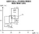
図15に戻り、ステップS83にて条件5が成立しないと判定した場合(ステップS83;No)、調停部13は、処理をステップS82に移行する。一方、条件5が成立すると判定した場合(ステップS83;Yes)、調停部13は、条件6が成立するか否かを判定する(ステップS84)。条件6は、在室する多数のユーザ20の現在における要望の範囲が重複する重複範囲と、少数のユーザ20の過去における要望の範囲と、が重複することである。図11に示される例においては、ユーザ2cが少数のユーザ20に相当する。そこで、調停部13は、重複範囲71とユーザ2cの過去における要望の範囲とが重複するか否かを判定する。ここで、図18に示されるように、ユーザ2cの過去における要望の範囲61c,63cが、重複範囲71に重複することから、条件6が成立する。 Returning to FIG. 15, when it is determined in step S83 that the condition 5 is not satisfied (step S83; No), the
図15に戻り、ステップS84にて条件6が成立すると判定した場合(ステップS84;Yes)、調停部13は、多数のユーザ20の現在における要望の範囲が重複する重複範囲と、少数のユーザが過去に選択した割合が最も大きい範囲と、が重複する範囲を目標範囲に設定する(ステップS85)。図18に示される例において、重複範囲71と重複する範囲61c,63のうち要望度が最も高いのは、図3を参照するとわかるように、要望度が70%である範囲61cである。そのため、調停部13は、図18に示される重複範囲71と範囲61cとの重複する範囲75を目標範囲に設定する。図15に戻り、ステップS85の終了後に、空調制御装置10による処理は、図8に示される空調制御処理に戻る。 Returning to FIG. 15, when it is determined in step S84 that the condition 6 is satisfied (step S84; Yes), the
一方、ステップS84にて条件6が成立しないと判定した場合(ステップS84;No)、調停部13は、多数のユーザ20の現在における要望の範囲が重複する重複範囲を目標範囲に設定する(ステップS86)。図11に示される例において、ユーザ2cの過去における要望の範囲がいずれも重複範囲71と重複しない場合には、条件6が成立せず、調停部13は、重複範囲71を目標範囲に設定する。図15に戻り、ステップS86の終了後に、空調制御装置10による処理は、図8に示される空調制御処理に戻る。 On the other hand, when it is determined in step S84 that the condition 6 is not satisfied (step S84; No), the
図8のステップS7に相当する第1調停処理又はステップS8に相当する第2調停処理に続いて、空調制御装置10は、制御データ122に基づいて空調装置40を制御することにより、第1調停処理又は第2調停処理で得た目標範囲内に空間200における空気の状態を収める(ステップS9)。具体的には、制御部14が、第1調停処理又は第2調停処理で決定された目標範囲内の制御目標値を制御データ122に基づいて設定し、この制御目標値に空気の状態が等しくなるように空調装置40を制御するための制御信号を送信する。ステップS9は、請求項の制御ステップに対応する。 Following the first arbitration process corresponding to step S7 in FIG. 8 or the second arbitration process corresponding to step S8, the air
図19には、制御データ122の一例が示されている。この制御データ122は、目標範囲に含まれる制御目標値を決定するためのルールと、そのルールの優先度と、を関連付けるテーブル形式のデータである。優先度が最も低い「1」の決定ルールは、「集中」モードに基づいて目標範囲が決定された場合、目標範囲の上限を制御目標値に決定することである。例えば、「集中」モードを選択することで要望される温度範囲が24−26℃であれば、26℃が制御目標値に決定される。これにより、エネルギー消費量を節約することができる。また、優先度が「2」の決定ルールは、「リラックス」モードに基づいて目標範囲が決定された場合、目標範囲の中央を制御目標値に決定することである。例えば、「リラックス」モードを選択することで要望される温度範囲が25−27℃であれば、26℃が制御目標値に決定される。これにより、ユーザに快適な空間を確実に提供することができる。また、優先度が最も高い「3」の決定ルールは、「アクティブ」モードに基づいて目標範囲が決定された場合、目標範囲の下限を制御目標範囲に設定することである。例えば、「アクティブ」モードを選択することで要望される温度範囲が20−22℃であれば、20℃が制御目標値に決定される。これにより、ユーザ20の活動を促進することが期待される。 FIG. 19 shows an example of the
空調制御装置10は、この制御データ122に基づいて制御目標値を設定する。例えば、「集中」モードに対応する範囲61aと「リラックス」モードに対応する範囲62bとの重複範囲が目標範囲として決定された場合には、優先度「1」及び「2」のルールが適用され、これらのルールのうち優先度が高い「2」のルールにより最終的な制御目標値が決定される。 The air
以上、説明したように、受信部11が、第1のユーザ20の第1要望を示す第1信号と第2のユーザ20の第2要望を示す第2信号とを受信し、制御部14が、現在における第1要望及び第2要望の少なくとも一方に関する条件が成立したときに、現在又は過去における第1要望の範囲と過去における第2要望の範囲とが重複する目標範囲内に空気の状態を収める。ユーザ20の過去の要望は、ユーザ20の次善としての要望に等しいものと考えられる。このため、条件が成立したときには、ユーザ20が次善として要望する範囲を目標として、空調装置が制御される。これにより、複数のユーザの快適性を向上させることができる。 As described above, the receiving unit 11 receives the first signal indicating the first request of the
具体的には、空調制御装置10は、図8に示されるように条件1が成立し、図13に示されるように条件2,3が成立したときに、在室する第1のユーザ20を含む複数のユーザ20の現在における要望の範囲が重複する重複範囲と、不在の第2のユーザ20の過去における要望の範囲と、が重複する範囲を目標範囲として空調装置40を制御した。これにより、不在のユーザ20が空間200内に戻ってきた際に空調制御の設定が変更される確率が低くなり、安定した空調制御が実行されることが期待される。ひいては、複数のユーザ20の快適性を向上させることができる。 Specifically, the air
また、空調制御装置10は、図8に示されるように条件1が成立せず、図15に示されるように条件4が成立するとき又は条件5が成立しないときに、第1のユーザ20及び第2のユーザ20を含む複数のユーザ20それぞれの過去における要望の範囲が重複する範囲を目標範囲として空調装置40を制御した。これにより、各ユーザ20の次善として要望する範囲を目標として制御をすることができ、複数のユーザの快適性を向上させることができる。 Further, in the air
なお、一の条件が成立しないときは、当該一の条件とは反対の条件が成立するときに等しい。このため、空調制御装置10は、条件1,5とは反対の条件1a,5aが成立するときに、図15に示されるステップ82を実行するといえる。条件1aは、在室する全ユーザ20の現在の要望の範囲が重複しないことであり、条件5aは、在室する多数のユーザ20の現在における要望の範囲が重複しないことである。 When one condition is not satisfied, it is the same as when the opposite condition to the one condition is satisfied. Therefore, it can be said that the air
また、空調制御装置10は、図8に示されるように条件1が成立せず、図15に示されるように条件6が成立したときに、多数のユーザ20それぞれの現在における要望の重複範囲と、少数のユーザ20の過去における要望の範囲と、の重複する範囲を目標範囲として空調装置40を制御した。これにより、第1のユーザ20及び第3のユーザ20を含む多数のユーザ20の要望に応えつつ、第2のユーザ20を含む少数のユーザ20が次善として要望する範囲を目標として制御をすることができ、複数のユーザの快適性を向上させることができる。 Further, in the air
以上、本発明の実施の形態について説明したが、本発明は上記実施の形態によって限定されるものではない。 Although the embodiments of the present invention have been described above, the present invention is not limited to the above embodiments.
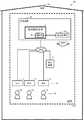
例えば、図20に示されるように、空調制御装置10は、室内機である空調装置40と連動する室外機としての空調装置41を制御することで、間接的に空調装置40を制御してもよい。 For example, as shown in FIG. 20, even if the air
また、図21に示されるように、複数の端末30のうち親機に相当する端末31が子機の端末32,33を統括して管理するとともに、空調制御装置10の機能を有してもよい。この場合には、受信部11は、端末31を構成するUI(User Interface)部311からユーザ2aの要望を示す信号を受信することとなる。 Further, as shown in FIG. 21, even if the terminal 31 corresponding to the master unit among the plurality of
また、図22に示されるように、空調装置40が空調制御装置10の機能を有してもよい。この場合には、制御部14は、空調装置40を構成する気流生成部401に制御信号を送信することで、空調装置40を制御することとなる。気流生成部401は、空調空気を生成する部材であって、例えばモータ及びファンを含む。 Further, as shown in FIG. 22, the
また、図23に示されるように、空調制御装置10を外部のサーバ装置60にネットワークを介して接続し、記憶部12及び調停部13を省いて空調制御装置10を構成してもよい。この場合には、サーバ装置60が、上述の実施の形態に係る記憶部12及び調停部13の機能を発揮する。 Further, as shown in FIG. 23, the air
また、空気の状態は、温度及び湿度に限られない。空気の状態は、空調装置40が吹き出す気流の強さ、二酸化炭素濃度、及び粉塵の濃度を含んでもよい。また、温度及び湿度の一方を空気の状態としてもよい。 Moreover, the state of air is not limited to temperature and humidity. The air condition may include the strength of the airflow blown out by the
また、上記実施の形態における検出装置50は、入退室管理システムであったが、これには限定されない。検出装置50は、他の手法によりユーザ20の在室及び不在を検出する装置であってもよい。例えば、検出装置50は、空間200に設置された無線LAN端末とユーザ20が所持する端末30との通信状況を監視することでユーザ20の所在を検出してもよい。また、検出装置50は、空間200に設置された監視カメラによって撮影された映像からユーザ20の顔を認識することにより各ユーザ20の所在を検出してもよい。また、検出装置50は、空調装置40に設けられた赤外線カメラによって撮影された映像と予め計測されたユーザ20の体温との比較に基づいて各ユーザ20の所在を検出してもよい。 Further, the
また、ユーザ20の数は3人に限られず、3人より少なくてもよいし3人より多くてもよい。また、各ユーザ20が選択するモードの数は3つに限られず、3つより少なくてもよいし3つより多くてもよい。また、モードのラベルは、ユーザ20が任意に変更してもよい。また、モードに対応する範囲は、ユーザ20が任意に変更してもよい。 Further, the number of
また、要望の範囲は図2に示されるような長方形の領域でなくてもよい。例えば、ユーザが希望する値を中心とする円形の領域であってもよい。 Further, the requested range does not have to be a rectangular area as shown in FIG. For example, it may be a circular area centered on a value desired by the user.
また、空調制御装置10の機能は、専用のハードウェアによっても、また、通常のコンピュータシステムによっても実現することができる。 Further, the function of the air
例えば、プロセッサ101によって実行されるプログラムP1を、コンピュータ読み取り可能な非一時的な記録媒体に格納して配布し、そのプログラムP1をコンピュータにインストールすることにより、上述の処理を実行する装置を構成することができる。このような記録媒体としては、例えばフレキシブルディスク、CD−ROM(Compact Disc Read−Only Memory)、DVD(Digital Versatile Disc)、MO(Magneto−Optical Disc)が考えられる。 For example, the program P1 executed by the
また、プログラムP1をインターネットに代表される通信ネットワーク上のサーバ装置が有するディスク装置に格納しておき、例えば、搬送波に重畳させて、コンピュータにダウンロードするようにしてもよい。 Further, the program P1 may be stored in a disk device of a server device on a communication network represented by the Internet, superimposed on a carrier wave, and downloaded to a computer, for example.
また、通信ネットワークを介してプログラムP1を転送しながら起動実行することによっても、上述の処理を達成することができる。 The above process can also be achieved by starting and executing the program P1 while transferring it via the communication network.
さらに、プログラムP1の全部又は一部をサーバ装置上で実行させ、その処理に関する情報をコンピュータが通信ネットワークを介して送受信しながらプログラムを実行することによっても、上述の処理を達成することができる。 Further, the above-mentioned processing can also be achieved by executing all or a part of the program P1 on the server device and executing the program while the computer sends and receives information about the processing via the communication network.
なお、上述の機能を、OS(Operating System)が分担して実現する場合又はOSとアプリケーションとの協働により実現する場合等には、OS以外の部分のみを媒体に格納して配布してもよく、また、コンピュータにダウンロードしてもよい。 If the above-mentioned functions are shared by the OS (Operating System) or realized by collaboration between the OS and the application, only the parts other than the OS may be stored and distributed in the medium. Well, you may also download it to your computer.
また、空調制御装置10の機能を実現する手段は、ソフトウェアに限られず、その一部又は全部を、回路を含む専用のハードウェアによって実現してもよい。 Further, the means for realizing the function of the air
本発明は、本発明の広義の精神と範囲を逸脱することなく、様々な実施の形態及び変形が可能とされるものである。また、上述した実施の形態は、本発明を説明するためのものであり、本発明の範囲を限定するものではない。つまり、本発明の範囲は、実施の形態ではなく、請求の範囲によって示される。そして、請求の範囲内及びそれと同等の発明の意義の範囲内で施される様々な変形が、本発明の範囲内とみなされる。 The present invention allows for various embodiments and modifications without departing from the broad spirit and scope of the present invention. Moreover, the above-described embodiment is for explaining the present invention, and does not limit the scope of the present invention. That is, the scope of the present invention is indicated not by the embodiment but by the claims. Then, various modifications made within the scope of the claims and within the equivalent meaning of the invention are considered to be within the scope of the present invention.
本発明は、複数のユーザが存在する空間の空調に適している。 The present invention is suitable for air conditioning in a space where a plurality of users exist.
100 空調制御システム、 110 建物、 10 空調制御装置、 11 受信部、 12 記憶部、 121 要望データ、 122 制御データ、 13 調停部、 14 制御部、 101 プロセッサ、 102 主記憶部、 103 補助記憶部、 104 入力部、 105 出力部、 106 通信部、 107 内部バス、 200 空間、 20,2a,2b,2c ユーザ、 30〜33 端末、 40,41 空調装置、 50 検出装置、 60 サーバ装置、 61a,61b,61c,61d,61e,61f,62a,62b,62c,63,63a,63b,63c,73,75 範囲、 71,72,74 重複範囲、 401 気流生成部、 P1 プログラム。 100 Air-conditioning control system, 110 Building, 10 Air-conditioning control device, 11 Receiver, 12 Storage unit, 121 Request data, 122 Control data, 13 Mediation unit, 14 Control unit, 101 Processor, 102 Main storage unit, 103 Auxiliary storage unit, 104 input unit, 105 output unit, 106 communication unit, 107 internal bus, 200 space, 20, 2a, 2b, 2c user, 30 to 33 terminals, 40, 41 air conditioner, 50 detector, 60 server device, 61a, 61b , 61c, 61d, 61e, 61f, 62a, 62b, 62c, 63, 63a, 63b, 63c, 73,75 range, 71,72,74 overlap range, 401 air flow generator, P1 program.
Claims (8)
Translated fromJapanese現在における前記第1要望及び前記第2要望の少なくとも一方に関する条件が成立したときに、制御信号を送信して、前記空気を調和する空調装置を制御することにより、現在又は過去における前記第1要望の範囲と過去における前記第2要望の範囲とが重複する目標範囲内に前記空気の状態を収める制御手段と、
を備え、
前記第2要望は、前記第2ユーザに関して予め定められた2以上の範囲からいずれかの範囲を選択する要望であり、
過去における前記第2要望の範囲は、前記2以上の範囲のうち、過去に選択された割合が最も大きい範囲である、空調制御装置。Receiving means for receiving the first signal indicating the first request of the first user and the second signal indicating the second request of the second user regarding the range of the air condition in the space to be air-conditioned.
When the conditions relating to at least one of the first request and the second request at present are satisfied, the first request in the present or the past is performed by transmitting a control signal to control the air conditioner that harmonizes the air. And the control means for keeping the air condition within the target range where the range of the above and the range of the second request in the past overlap.
Equipped witha,
The second request is a request to select one of two or more predetermined ranges with respect to the second user.
The range of the second request in the past is an air conditioning control devicein which the ratio selected in the past is the largest among the two or more ranges.
請求項1に記載の空調制御装置。The control means controls the air conditioner when the conditions are satisfied after the air conditioning by the air conditioner for the first request and the second request in the past is completed, thereby controlling the target range. Put the air condition inside,
The air conditioning control device according to claim 1.
請求項1又は2に記載の空調制御装置。The range of the second request in the past is a range that overlaps with the range of the first request in the present or the past among the two or more ranges, and is the range in which the ratio selected in the past is the largest.
The air conditioning control device according to claim1 or 2.
前記受信手段は、前記第2ユーザが前記空間の外にいることを示す検出信号を前記検出装置から受信し、
前記条件は、前記受信手段によって前記検出信号が受信され、現在における前記第2要望を示す前記第2信号が受信されていないことであって、
前記制御手段は、前記空調装置を制御することにより、現在における前記第1要望の範囲と過去における前記第2要望の範囲とが重複する前記目標範囲内に前記空気の状態を収める、
請求項1から3のいずれか一項に記載の空調制御装置。An air conditioning control device connected to a detection device that detects that the second user is outside the space.
The receiving means receives a detection signal indicating that the second user is outside the space from the detection device, and receives the detection signal.
The condition is that the detection signal is received by the receiving means, and the second signal indicating the second request at present is not received.
By controlling the air conditioner, the control means keeps the air state within the target range in which the current range of the first request and the range of the second request in the past overlap.
The air conditioning control device according to any one of claims 1 to3.
前記制御手段は、前記空調装置を制御することにより、過去における前記第1要望の範囲と過去における前記第2要望の範囲とが重複する前記目標範囲内に前記空気の状態を収める、
請求項1から3のいずれか一項に記載の空調制御装置。The condition is that the current range of the second request is outside the current range of the first request.
By controlling the air conditioner, the control means keeps the air state within the target range in which the range of the first request in the past and the range of the second request in the past overlap.
The air conditioning control device according to any one of claims 1 to3.
前記条件は、現在における前記第1要望と現在における前記第3要望とが重複する重複範囲の外部に現在における前記第2要望の範囲があることであって、
前記制御手段は、前記重複範囲と過去における前記第2要望の範囲とが重複する前記目標範囲内に前記空気の状態を収める、
請求項1から3のいずれか一項に記載の空調制御装置。The receiving means receives a third signal indicating a third request of the third user for the range of the air condition.
The condition is that the current range of the second request is outside the overlapping range in which the current first request and the current third request overlap.
The control means keeps the state of air within the target range where the overlapping range and the range of the second request in the past overlap.
The air conditioning control device according to any one of claims 1 to3.
前記空調装置を制御する請求項1から6のいずれか一項に記載の空調制御装置と、
を備える空調制御システム。An air conditioner that harmonizes the air in the space to be air-conditioned,
The air-conditioning control device according to any one of claims 1 to 6 , which controls the air-conditioning device, and the air-conditioning control device.
Air conditioning control system equipped with.
現在における前記第1要望及び前記第2要望の少なくとも一方に関する条件が成立したときに、制御信号を送信することにより、現在又は過去における前記第1要望の範囲と過去における前記第2要望の範囲とが重複する目標範囲内に前記空気の状態を収める制御ステップと、
を含み、
前記第2要望は、前記第2ユーザに関して予め定められた2以上の範囲からいずれかの範囲を選択する要望であり、
過去における前記第2要望の範囲は、前記2以上の範囲のうち、過去に選択された割合が最も大きい範囲である、空調制御方法。Regarding the range of the air condition in the space to be air-conditioned, the reception step of receiving the first signal indicating the first request of the first user and the second signal indicating the second request of the second user, and
By transmitting a control signal when the conditions relating to at least one of the first request and the second request at present are satisfied, the range of the first request in the present or the past and the range of the second request in the past can be obtained. A control step that keeps the air condition within the overlapping target range,
Only including,
The second request is a request to select one of two or more predetermined ranges with respect to the second user.
The range of the second request in the past is the range in which the ratio selected in the past is the largest among the ranges of two or more . The air conditioning control method.
Applications Claiming Priority (1)
| Application Number | Priority Date | Filing Date | Title |
|---|---|---|---|
| PCT/JP2018/027097WO2020016993A1 (en) | 2018-07-19 | 2018-07-19 | Air conditioning control device, air conditioning control system, and air conditioning control method |
Publications (2)
| Publication Number | Publication Date |
|---|---|
| JPWO2020016993A1 JPWO2020016993A1 (en) | 2020-12-17 |
| JP6949231B2true JP6949231B2 (en) | 2021-10-13 |
Family
ID=69164405
Family Applications (1)
| Application Number | Title | Priority Date | Filing Date |
|---|---|---|---|
| JP2020530812AExpired - Fee RelatedJP6949231B2 (en) | 2018-07-19 | 2018-07-19 | Air conditioning control device, air conditioning control system and air conditioning control method |
Country Status (2)
| Country | Link |
|---|---|
| JP (1) | JP6949231B2 (en) |
| WO (1) | WO2020016993A1 (en) |
Families Citing this family (1)
| Publication number | Priority date | Publication date | Assignee | Title |
|---|---|---|---|---|
| JP2024130383A (en)* | 2023-03-14 | 2024-09-30 | 株式会社東芝 | Information processing device, information processing method, information processing program, and information processing system |
Family Cites Families (4)
| Publication number | Priority date | Publication date | Assignee | Title |
|---|---|---|---|---|
| JP2005172288A (en)* | 2003-12-09 | 2005-06-30 | Mitsubishi Heavy Ind Ltd | Controlling system for air conditioner |
| JP4826351B2 (en)* | 2006-06-12 | 2011-11-30 | ダイキン工業株式会社 | Environmental control device |
| JP4871331B2 (en)* | 2008-08-21 | 2012-02-08 | ヤフー株式会社 | System and method for promoting eco activities |
| CA2668812A1 (en)* | 2009-06-12 | 2010-12-12 | Ibm Canada Limited - Ibm Canada Limitee | Method and system for grid-based hvac |
- 2018
- 2018-07-19JPJP2020530812Apatent/JP6949231B2/ennot_activeExpired - Fee Related
- 2018-07-19WOPCT/JP2018/027097patent/WO2020016993A1/ennot_activeCeased
Also Published As
| Publication number | Publication date |
|---|---|
| WO2020016993A1 (en) | 2020-01-23 |
| JPWO2020016993A1 (en) | 2020-12-17 |
Similar Documents
| Publication | Publication Date | Title |
|---|---|---|
| JP5878848B2 (en) | Device control device, program, device control server, device control system | |
| US10101052B2 (en) | Location-based approaches for controlling an energy consuming device | |
| US12276431B2 (en) | Control device, air conditioner and control method thereof | |
| US20090065596A1 (en) | Systems and methods for increasing building space comfort using wireless devices | |
| JP2007078221A (en) | Air conditioning control system | |
| JP6777174B2 (en) | Server equipment, adapters and air conditioning systems | |
| CN117529754A (en) | System and method for on-device personnel identification and provision of intelligent alarms | |
| WO2019008960A1 (en) | Air conditioning control device, environmental setting terminal, air conditioning control method, and program | |
| JPWO2018087912A1 (en) | Control device and control system | |
| CN110430529B (en) | Method and device for voice assistant reminder | |
| JP2023060335A (en) | Adaptor | |
| JP6949231B2 (en) | Air conditioning control device, air conditioning control system and air conditioning control method | |
| JP2020125868A (en) | Air conditioning system | |
| JP6833056B2 (en) | Control device, environmental adjustment system, environmental adjustment method and program | |
| JP7392394B2 (en) | Air conditioning system and air conditioner | |
| JP7342363B2 (en) | Adapter, update notification method and air conditioning system | |
| US20220329497A1 (en) | EDGE DEVICE LINKING SYSTEM, EDGE DEVICE LINKING METHOD, AND RECORDING MEDIUM (as amended) | |
| WO2019186993A1 (en) | Terminal apparatus, device control system, device control method, and program | |
| JP6833102B1 (en) | Environmental control system, environmental control method and environmental control program | |
| JP7363039B2 (en) | air conditioning system | |
| CN116045475B (en) | Control method and device for air conditioning system of bus station and air conditioning control system | |
| US20240011660A1 (en) | Air-conditioning control system, control device, air-conditioning control method, and recording medium | |
| JP7534157B2 (en) | Environmental control system and environmental control method | |
| JP7437531B2 (en) | air conditioning system | |
| JP7580585B2 (en) | Air conditioning system, control device, air conditioning control method and program |
Legal Events
| Date | Code | Title | Description |
|---|---|---|---|
| A521 | Request for written amendment filed | Free format text:JAPANESE INTERMEDIATE CODE: A523 Effective date:20200707 | |
| A621 | Written request for application examination | Free format text:JAPANESE INTERMEDIATE CODE: A621 Effective date:20200707 | |
| TRDD | Decision of grant or rejection written | ||
| A01 | Written decision to grant a patent or to grant a registration (utility model) | Free format text:JAPANESE INTERMEDIATE CODE: A01 Effective date:20210824 | |
| A61 | First payment of annual fees (during grant procedure) | Free format text:JAPANESE INTERMEDIATE CODE: A61 Effective date:20210921 | |
| R150 | Certificate of patent or registration of utility model | Ref document number:6949231 Country of ref document:JP Free format text:JAPANESE INTERMEDIATE CODE: R150 | |
| LAPS | Cancellation because of no payment of annual fees |