JP6948487B1 - Electrostatic coating equipment - Google Patents
Electrostatic coating equipmentDownload PDFInfo
- Publication number
- JP6948487B1 JP6948487B1JP2021103758AJP2021103758AJP6948487B1JP 6948487 B1JP6948487 B1JP 6948487B1JP 2021103758 AJP2021103758 AJP 2021103758AJP 2021103758 AJP2021103758 AJP 2021103758AJP 6948487 B1JP6948487 B1JP 6948487B1
- Authority
- JP
- Japan
- Prior art keywords
- air
- head portion
- passage
- arm portion
- electrostatic coating
- Prior art date
- Legal status (The legal status is an assumption and is not a legal conclusion. Google has not performed a legal analysis and makes no representation as to the accuracy of the status listed.)
- Active
Links
Images


Classifications
- B—PERFORMING OPERATIONS; TRANSPORTING
- B05—SPRAYING OR ATOMISING IN GENERAL; APPLYING FLUENT MATERIALS TO SURFACES, IN GENERAL
- B05B—SPRAYING APPARATUS; ATOMISING APPARATUS; NOZZLES
- B05B5/00—Electrostatic spraying apparatus; Spraying apparatus with means for charging the spray electrically; Apparatus for spraying liquids or other fluent materials by other electric means
- B05B5/025—Discharge apparatus, e.g. electrostatic spray guns
- B05B5/04—Discharge apparatus, e.g. electrostatic spray guns characterised by having rotary outlet or deflecting elements, i.e. spraying being also effected by centrifugal forces
- B05B5/0415—Driving means; Parts thereof, e.g. turbine, shaft, bearings
- B—PERFORMING OPERATIONS; TRANSPORTING
- B05—SPRAYING OR ATOMISING IN GENERAL; APPLYING FLUENT MATERIALS TO SURFACES, IN GENERAL
- B05B—SPRAYING APPARATUS; ATOMISING APPARATUS; NOZZLES
- B05B5/00—Electrostatic spraying apparatus; Spraying apparatus with means for charging the spray electrically; Apparatus for spraying liquids or other fluent materials by other electric means
- B05B5/08—Plant for applying liquids or other fluent materials to objects
- B—PERFORMING OPERATIONS; TRANSPORTING
- B05—SPRAYING OR ATOMISING IN GENERAL; APPLYING FLUENT MATERIALS TO SURFACES, IN GENERAL
- B05B—SPRAYING APPARATUS; ATOMISING APPARATUS; NOZZLES
- B05B5/00—Electrostatic spraying apparatus; Spraying apparatus with means for charging the spray electrically; Apparatus for spraying liquids or other fluent materials by other electric means
- B05B5/025—Discharge apparatus, e.g. electrostatic spray guns
- B05B5/04—Discharge apparatus, e.g. electrostatic spray guns characterised by having rotary outlet or deflecting elements, i.e. spraying being also effected by centrifugal forces
- B05B5/0403—Discharge apparatus, e.g. electrostatic spray guns characterised by having rotary outlet or deflecting elements, i.e. spraying being also effected by centrifugal forces characterised by the rotating member
- B05B5/0407—Discharge apparatus, e.g. electrostatic spray guns characterised by having rotary outlet or deflecting elements, i.e. spraying being also effected by centrifugal forces characterised by the rotating member with a spraying edge, e.g. like a cup or a bell
- B—PERFORMING OPERATIONS; TRANSPORTING
- B05—SPRAYING OR ATOMISING IN GENERAL; APPLYING FLUENT MATERIALS TO SURFACES, IN GENERAL
- B05B—SPRAYING APPARATUS; ATOMISING APPARATUS; NOZZLES
- B05B1/00—Nozzles, spray heads or other outlets, with or without auxiliary devices such as valves, heating means
- B05B1/30—Nozzles, spray heads or other outlets, with or without auxiliary devices such as valves, heating means designed to control volume of flow, e.g. with adjustable passages
- B05B1/3033—Nozzles, spray heads or other outlets, with or without auxiliary devices such as valves, heating means designed to control volume of flow, e.g. with adjustable passages the control being effected by relative coaxial longitudinal movement of the controlling element and the spray head
- B05B1/304—Nozzles, spray heads or other outlets, with or without auxiliary devices such as valves, heating means designed to control volume of flow, e.g. with adjustable passages the control being effected by relative coaxial longitudinal movement of the controlling element and the spray head the controlling element being a lift valve
- B05B1/3046—Nozzles, spray heads or other outlets, with or without auxiliary devices such as valves, heating means designed to control volume of flow, e.g. with adjustable passages the control being effected by relative coaxial longitudinal movement of the controlling element and the spray head the controlling element being a lift valve the valve element, e.g. a needle, co-operating with a valve seat located downstream of the valve element and its actuating means, generally in the proximity of the outlet orifice
- B05B1/306—Nozzles, spray heads or other outlets, with or without auxiliary devices such as valves, heating means designed to control volume of flow, e.g. with adjustable passages the control being effected by relative coaxial longitudinal movement of the controlling element and the spray head the controlling element being a lift valve the valve element, e.g. a needle, co-operating with a valve seat located downstream of the valve element and its actuating means, generally in the proximity of the outlet orifice the actuating means being a fluid
- B—PERFORMING OPERATIONS; TRANSPORTING
- B05—SPRAYING OR ATOMISING IN GENERAL; APPLYING FLUENT MATERIALS TO SURFACES, IN GENERAL
- B05B—SPRAYING APPARATUS; ATOMISING APPARATUS; NOZZLES
- B05B12/00—Arrangements for controlling delivery; Arrangements for controlling the spray area
- B05B12/14—Arrangements for controlling delivery; Arrangements for controlling the spray area for supplying a selected one of a plurality of liquids or other fluent materials or several in selected proportions to a spray apparatus, e.g. to a single spray outlet
- B05B12/149—Arrangements for controlling delivery; Arrangements for controlling the spray area for supplying a selected one of a plurality of liquids or other fluent materials or several in selected proportions to a spray apparatus, e.g. to a single spray outlet characterised by colour change manifolds or valves therefor
- B—PERFORMING OPERATIONS; TRANSPORTING
- B05—SPRAYING OR ATOMISING IN GENERAL; APPLYING FLUENT MATERIALS TO SURFACES, IN GENERAL
- B05B—SPRAYING APPARATUS; ATOMISING APPARATUS; NOZZLES
- B05B15/00—Details of spraying plant or spraying apparatus not otherwise provided for; Accessories
- B05B15/14—Arrangements for preventing or controlling structural damage to spraying apparatus or its outlets, e.g. for breaking at desired places; Arrangements for handling or replacing damaged parts
- B05B15/18—Arrangements for preventing or controlling structural damage to spraying apparatus or its outlets, e.g. for breaking at desired places; Arrangements for handling or replacing damaged parts for improving resistance to wear, e.g. inserts or coatings; for indicating wear; for handling or replacing worn parts
- B—PERFORMING OPERATIONS; TRANSPORTING
- B05—SPRAYING OR ATOMISING IN GENERAL; APPLYING FLUENT MATERIALS TO SURFACES, IN GENERAL
- B05B—SPRAYING APPARATUS; ATOMISING APPARATUS; NOZZLES
- B05B5/00—Electrostatic spraying apparatus; Spraying apparatus with means for charging the spray electrically; Apparatus for spraying liquids or other fluent materials by other electric means
- B05B5/025—Discharge apparatus, e.g. electrostatic spray guns
- B05B5/04—Discharge apparatus, e.g. electrostatic spray guns characterised by having rotary outlet or deflecting elements, i.e. spraying being also effected by centrifugal forces
- B05B5/0426—Means for supplying shaping gas
- B—PERFORMING OPERATIONS; TRANSPORTING
- B05—SPRAYING OR ATOMISING IN GENERAL; APPLYING FLUENT MATERIALS TO SURFACES, IN GENERAL
- B05B—SPRAYING APPARATUS; ATOMISING APPARATUS; NOZZLES
- B05B5/00—Electrostatic spraying apparatus; Spraying apparatus with means for charging the spray electrically; Apparatus for spraying liquids or other fluent materials by other electric means
- B05B5/08—Plant for applying liquids or other fluent materials to objects
- B05B5/10—Arrangements for supplying power, e.g. charging power
- B—PERFORMING OPERATIONS; TRANSPORTING
- B05—SPRAYING OR ATOMISING IN GENERAL; APPLYING FLUENT MATERIALS TO SURFACES, IN GENERAL
- B05B—SPRAYING APPARATUS; ATOMISING APPARATUS; NOZZLES
- B05B13/00—Machines or plants for applying liquids or other fluent materials to surfaces of objects or other work by spraying, not covered by groups B05B1/00 - B05B11/00
- B05B13/02—Means for supporting work; Arrangement or mounting of spray heads; Adaptation or arrangement of means for feeding work
- B05B13/04—Means for supporting work; Arrangement or mounting of spray heads; Adaptation or arrangement of means for feeding work the spray heads being moved during spraying operation
- B05B13/0431—Means for supporting work; Arrangement or mounting of spray heads; Adaptation or arrangement of means for feeding work the spray heads being moved during spraying operation with spray heads moved by robots or articulated arms, e.g. for applying liquid or other fluent material to three-dimensional [3D] surfaces
- B—PERFORMING OPERATIONS; TRANSPORTING
- B05—SPRAYING OR ATOMISING IN GENERAL; APPLYING FLUENT MATERIALS TO SURFACES, IN GENERAL
- B05B—SPRAYING APPARATUS; ATOMISING APPARATUS; NOZZLES
- B05B15/00—Details of spraying plant or spraying apparatus not otherwise provided for; Accessories
- B05B15/50—Arrangements for cleaning; Arrangements for preventing deposits, drying-out or blockage; Arrangements for detecting improper discharge caused by the presence of foreign matter
- B05B15/55—Arrangements for cleaning; Arrangements for preventing deposits, drying-out or blockage; Arrangements for detecting improper discharge caused by the presence of foreign matter using cleaning fluids
- B—PERFORMING OPERATIONS; TRANSPORTING
- B05—SPRAYING OR ATOMISING IN GENERAL; APPLYING FLUENT MATERIALS TO SURFACES, IN GENERAL
- B05B—SPRAYING APPARATUS; ATOMISING APPARATUS; NOZZLES
- B05B5/00—Electrostatic spraying apparatus; Spraying apparatus with means for charging the spray electrically; Apparatus for spraying liquids or other fluent materials by other electric means
- B05B5/025—Discharge apparatus, e.g. electrostatic spray guns
- B05B5/043—Discharge apparatus, e.g. electrostatic spray guns using induction-charging
Landscapes
- Electrostatic Spraying Apparatus (AREA)
- Spray Control Apparatus (AREA)
Abstract
Translated fromJapaneseDescription
Translated fromJapanese本発明は、塗料に直接的に高電圧を印加して塗装を行う静電塗装装置に関する。 The present invention relates to an electrostatic coating apparatus that applies a high voltage directly to a coating material to perform coating.
一般に、自動車のボディ等の被塗物を塗装する塗装装置は、基端側が塗装用ロボット等の動作装置に取付けられるアーム部と、アーム部の先端側に設けられたヘッド部と、ヘッド部に設けられ、圧縮エアを動力源とするエアモータと、エアモータに回転自在に支持され、先端がエアモータから前側に突出した中空な回転軸と、塗料を供給するために回転軸内を通って回転軸の先端まで延びたフィードチューブと、回転軸の先端に取付けられ、フィードチューブから供給された塗料を被塗物に向けて噴霧する回転霧化頭と、ヘッド部に設けられ、フィードチューブへの塗料の供給経路をパイロットエアによって開閉するトリガ弁を含む切換弁を備えた弁装置と、ヘッド部の外周側を覆う樹脂製の筒状体として形成されたカバー部と、を備えている。 Generally, a coating device for painting an object to be coated such as an automobile body has an arm portion whose base end side is attached to an operating device such as a coating robot, a head portion provided on the tip end side of the arm portion, and a head portion. An air motor that is provided and powered by compressed air, a hollow rotating shaft that is rotatably supported by the air motor and whose tip protrudes forward from the air motor, and a rotating shaft that passes through the rotating shaft to supply paint. A feed tube that extends to the tip, a rotary atomizing head that is attached to the tip of the rotary shaft and sprays the paint supplied from the feed tube toward the object to be coated, and a rotary atomizing head that is provided on the head and attaches the paint to the feed tube. It includes a valve device including a switching valve including a trigger valve that opens and closes a supply path by pilot air, and a cover portion formed as a resin tubular body that covers the outer peripheral side of the head portion.
また、塗料の塗着効率を向上するための塗装装置としては、静電塗装装置が知られている。この静電塗装装置は、エアモータおよび回転軸を通じて回転霧化頭に供給される塗料に高電圧を印加する高電圧発生器をアーム部に備えている(特許文献1)。 Further, an electrostatic coating device is known as a coating device for improving the coating efficiency of the paint. This electrostatic coating device includes an air motor and a high voltage generator in the arm portion that applies a high voltage to the paint supplied to the rotary atomizing head through the rotating shaft (Patent Document 1).
特許文献1の静電塗装装置は、高電圧発生器で発生した高電圧をエアモータ、回転軸等に帯電させ、フィードチューブを通じて回転霧化頭に供給される塗料に高電圧を印加している。これにより、静電塗装装置は、回転霧化頭から噴霧した帯電塗料粒子を接地された被塗物に向けて飛行させている。 In the electrostatic coating device of
この場合、高電圧に帯電した金属製のエアモータや回転軸からはオゾンが放出される。これらの部品から放出されたオゾンは、エアモータの駆動源となる圧縮エア(排気)、塗料の噴霧パターンを整えるシェーピングエア等と一緒に排出される。 In this case, ozone is emitted from a metal air motor or a rotating shaft charged with a high voltage. The ozone emitted from these parts is discharged together with compressed air (exhaust), which is a driving source of the air motor, and shaping air, which adjusts the spray pattern of the paint.
しかし、静電塗装装置は、弁装置等の他の金属製の部品を備えており、弁装置等から放出されたオゾンは、ヘッド部とカバー部との隙間やアーム部とヘッド部との隙間に滞留してしまう。このように、滞留したオゾンは、次第に他の隙間にも広がって樹脂製の部品を腐食させる虞がある。腐食した部品は、高電圧のリークの原因にもなるために交換しなくてはならず、部品の耐久性が低下するという問題がある。 However, the electrostatic coating device is provided with other metal parts such as a valve device, and ozone emitted from the valve device or the like is a gap between the head portion and the cover portion or a gap between the arm portion and the head portion. Will stay in. In this way, the retained ozone may gradually spread to other gaps and corrode the resin parts. Corroded parts also cause high voltage leaks and must be replaced, which has the problem of reducing the durability of the parts.
本発明は上述した従来技術の問題に鑑みなされたもので、本発明の目的は、空気の流れがない隙間にオゾンが滞留するのを防止することにより、樹脂製部品の耐久性を向上できるようにした静電塗装装置を提供することにある。 The present invention has been made in view of the above-mentioned problems of the prior art, and an object of the present invention is to improve the durability of resin parts by preventing ozone from accumulating in gaps where there is no air flow. The purpose is to provide an electrostatic coating device.
本発明は、基端側が動作装置に取付けられるアーム部と、前記アーム部の先端側に設けられたヘッド部と、前記ヘッド部に設けられ、圧縮エアを動力源とするエアモータと、前記エアモータに回転自在に支持され、先端が前記エアモータから前側に突出した中空な回転軸と、塗料を供給するために前記回転軸内を通って前記回転軸の先端まで延びたフィードチューブと、前記回転軸の先端に取付けられ、前記フィードチューブから供給された塗料を被塗物に向けて噴霧する回転霧化頭と、前記ヘッド部に設けられ、前記フィードチューブへの塗料の供給経路をパイロットエアによって開閉するトリガ弁を含む切換弁を備えた弁装置と、前記アーム部に設けられ、前記弁装置、前記エアモータおよび前記回転軸を通じて前記回転霧化頭に供給される塗料に高電圧を印加する高電圧発生器と、前記ヘッド部の外周側を覆う樹脂製の筒状体として形成されたカバー部と、を備えてなる静電塗装装置において、前記ヘッド部と前記カバー部との間には、前記ヘッド部の外周側を取り囲むように筒状隙間が設けられ、前記ヘッド部には、前記切換弁から排出される前記パイロットエアを前記筒状隙間に導くパイロットエア導入路が設けられ、前記アーム部には、前記パイロットエアを前記筒状隙間から外部に排出するパイロットエア排出路が設けられている。 The present invention includes an arm portion whose base end side is attached to an operating device, a head portion provided on the tip end side of the arm portion, an air motor provided on the head portion and using compressed air as a power source, and the air motor. A hollow rotating shaft that is rotatably supported and whose tip protrudes forward from the air motor, a feed tube that passes through the rotating shaft to supply paint and extends to the tip of the rotating shaft, and a rotating shaft. A rotary atomizing head attached to the tip and spraying the paint supplied from the feed tube toward the object to be coated, and a pilot air provided on the head portion to open and close the paint supply path to the feed tube. A high voltage generation that applies a high voltage to a valve device including a switching valve including a trigger valve and a coating material provided on the arm portion and supplied to the rotary atomizing head through the valve device, the air motor, and the rotating shaft. In an electrostatic coating apparatus including a vessel and a cover portion formed as a resin tubular body that covers the outer peripheral side of the head portion, the head portion is between the head portion and the cover portion. A cylindrical gap is provided so as to surround the outer peripheral side of the portion, and the head portion is provided with a pilot air introduction path for guiding the pilot air discharged from the switching valve to the tubular gap, and the arm portion is provided with a pilot air introduction path. Is provided with a pilot air discharge path for discharging the pilot air to the outside through the cylindrical gap.
本発明によれば、空気の流れがない隙間にオゾンが滞留するのを防止することができ、樹脂製部品の耐久性を向上することができる。 According to the present invention, it is possible to prevent ozone from staying in a gap where there is no air flow, and it is possible to improve the durability of resin parts.
以下、本発明の実施形態に係る静電塗装装置について、図1ないし図5に従って詳細に説明する。 Hereinafter, the electrostatic coating apparatus according to the embodiment of the present invention will be described in detail with reference to FIGS. 1 to 5.
図1において、動作装置の代表例としての塗装用ロボット101は、基台102と、基台102上に動作可能に設けられた垂直アーム103と、垂直アーム103の先端に回動可能に設けられたアーム部としての水平アーム104と、を含んで構成されている。水平アーム104の先端部は、回転可能な手首部104Aとなっている。この手首部104Aには、後述する静電塗装装置1のアーム部2が取付けられている。 In FIG. 1, a
次に、本発明の実施形態に係る静電塗装装置1の構成について述べる。静電塗装装置1は、塗装用ロボット101の水平アーム104の手首部104Aに取付けられている。図2に示すように、静電塗装装置1は、後述のアーム部2、ヘッド部3、エアモータ6、回転軸7、フィードチューブ8、回転霧化頭9、弁装置11、高電圧発生器18、カバー部20、パイロットエア導入路22、パイロットエア排出路23を含んで構成されている。 Next, the configuration of the
アーム部2は、基端側となる長さ方向の基端部2Aが水平アーム104の手首部104Aの先端部に取付けられている。アーム部2は、樹脂製の円筒状体として形成されている。また、アーム部2の先端側は、斜めに屈曲している。アーム部2の先端部2Bには、円形状の平坦面からなる先端面2Cを有している。この先端面2Cは、後述するヘッド部3の基端面3Cおよび弁装置11を構成するベース部材12の基端面12Aと対面している。さらに、アーム部2の先端側には、先端面2Cの周囲に位置して、短尺な円形状の筒部2Dが設けられている。筒部2Dの内周面には、後述のシール部材5が密着している。 In the
アーム部2の内部には、軸方向に延びて後述の高電圧発生器18が設けられている。また、アーム部2の内部には、高電圧発生器18を取り囲む位置に後述のパイロットエア排出路23、第1二重管路24、第2二重管路27等が設けられている。 Inside the
ヘッド部3は、アーム部2の先端側に設けられている。ヘッド部3は、基端部3Aがアーム部2の先端部2Bに取付けられた樹脂製の円筒状体として形成されている。ヘッド部3内の基端部3A側には、後述の弁装置11が設けられている。また、ヘッド部3内の先端部3B側には、後述のエアモータ6、シェーピングエアリング10等が設けられている。 The
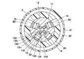
ヘッド部3の基端面3Cは、アーム部2の先端面2Cに後述の平面状隙間4を挟んで対面している。ヘッド部3の基端側には、弁装置11の外周側に位置して弁取付孔3Dが設けられている。図4に示すように、弁取付孔3Dは、ヘッド部3を径方向に貫通している。また、弁取付孔3Dは、周方向に間隔をもって複数個、例えば弁装置11の切換弁13〜16に対応して4個設けられている。 The
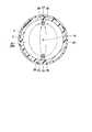
ここで、平面状隙間4は、アーム部2の先端部2Bとヘッド部3の基端部3Aとの間に設けられている。具体的には、平面状隙間4の大部分は、アーム部2の先端面2Cとヘッド部3の基端面3Cおよびベース部材12の基端面12Aとの間に設けられている。また、図5に示すように、平面状隙間4は、円形状に形成されている。この上で、平面状隙間4の外周側の一部は、アーム部2の筒部2Dに沿って先端側に延びている。なお、平面状隙間4は、大きな隙間として図示したが、実際には、例えば1mm以下の小さな隙間であり、アーム部2とヘッド部3とが部分的に接する部分があってもよい。 Here, the
シール部材5は、ヘッド部3の基端部3Aの外周側に設けられている。シール部材5は、樹脂製のOリング等からなり、アーム部2の筒部2Dの内周面に密着して平面状隙間4をシールしている。これにより、アーム部2の先端部2Bとヘッド部3の基端部3Aとは、周囲にシール部材5を挟んだ状態で互いに対面して取付けられている。 The
エアモータ6は、ヘッド部3内にヘッド部3と同軸に設けられている。エアモータ6は、圧縮エアを動力源として回転軸7および回転霧化頭9を、例えば3000〜150000rpmの高速で回転させる。エアモータ6は、ヘッド部3内に取付けられた段付円筒状のモータケース6Aと、モータケース6Aの基端側に回転可能に収容されたタービン6Bと、モータケース6Aの内周側に設けられ回転軸7を回転可能に支持するエア軸受6Cと、を含んで構成されている。 The
ここで、タービン6Bには、圧縮エア供給路(図示せず)を介して駆動用の圧縮エアが供給される。また、タービン6Bから流出する圧縮エアは、後述する第1二重管路24の圧縮エア排出路25と第2二重管路27の圧縮エア排出路28とを介して外部に排出される。 Here, the compressed air for driving is supplied to the
回転軸7は、エアモータ6にエア軸受6Cを介して回転自在に支持された筒状体として形成されている。回転軸7は、モータケース6Aの中心に軸方向に延びて配置されている。回転軸7は、基端側がタービン6Bの中央に一体的に取付けられている。一方、回転軸7は、先端がモータケース6Aから前側(先端側)に突出している。回転軸7の先端部には、回転霧化頭9が取付けられている。 The rotating shaft 7 is formed as a cylindrical body rotatably supported by the
フィードチューブ8は、回転軸7内を通って回転軸7の先端まで延びている。フィードチューブ8の先端側は、回転軸7の先端から突出して回転霧化頭9内に延在している。フィードチューブ8の基端側は、弁装置11のベース部材12の中央位置に取付けられている。フィードチューブ8は、内部の塗料通路(図示せず)が、後述の塗料供給路12Bを介して色替弁装置を含む塗料供給源(図示せず)に接続されている。なお、フィードチューブ8の基端側は、モータケース6Aの基端側に対面する位置にヘッド部を延在させることで、このヘッド部に取付ける構成としてもよい。 The
フィードチューブ8は、塗装作業を行うときに、塗料通路から回転霧化頭9に向けて塗料を供給する。一方、フィードチューブ8は、付着塗料の洗浄作業を行うときに、塗料通路から回転霧化頭9に向け、例えばシンナ、エア等の洗浄流体を供給することができる。例えば、フィードチューブ8は、同軸に配置された二重管として形成されている。この上で、二重管の中央の通路が塗料通路となり、外側の環状通路が洗浄流体通路(いずれも図示せず)となっている。 The
回転霧化頭9は、回転軸7の先端に取付けられている。回転霧化頭9は、基端側から先端側に向けて拡径するカップ状に形成されている。回転霧化頭9は、エアモータ6によって回転軸7と一緒に高速回転される。これにより、回転霧化頭9は、フィードチューブ8から供給される塗料等を噴霧する。 The rotary atomizing head 9 is attached to the tip of the rotary shaft 7. The rotary atomizing head 9 is formed in a cup shape whose diameter increases from the proximal end side to the distal end side. The rotary atomizing head 9 is rotated at high speed together with the rotating shaft 7 by the
シェーピングエアリング10は、回転霧化頭9を取囲んだ状態でヘッド部3の先端部3B側に設けられている。シェーピングエアリング10は、複数個のシェーピングエア噴出孔(図示せず)からシェーピングエアを噴出する。シェーピングエアは、回転霧化頭9から噴霧される塗料を微粒化しつつ、塗料の塗装パターンを所望の大きさ、形状に整える。 The shaping
弁装置11は、ヘッド部3内の基端部3A側に設けられている。図4に示すように、弁装置11は、後述のベース部材12、4個の切換弁13〜16を含んで構成されている。弁装置11は、各種流体の供給、停止、排出等の動作を制御する。 The
ベース部材12は、弁装置11のベースをなすもので、金属製のブロック体として形成されている。ベース部材12は、ヘッド部3内の基端側に取付けられている。ベース部材12は、アーム部2の先端面2Cと対面する基端面12Aを有している。例えば、ベース部材12には、フィードチューブ8への塗料の供給経路の一部をなす塗料供給路12B、フィードチューブ8に向けて回転霧化頭9を洗浄するための洗浄流体が流通する洗浄流体通路、塗料供給路12Bに残存した前色塗料を排出するときに前色塗料や洗浄流体が流通するダンプ通路、フィードチューブ8の先端に付着した塗料を洗浄するための洗浄流体が流通する先端洗浄通路(いずれも図示せず)が設けられている。 The
また、ベース部材12には、切換弁13〜16を動作させるためのパイロットエアが当該切換弁13〜16に向けて流通する後述のパイロットエア通路17(切換弁13用のみ図示)が設けられている。 Further, the
4個の切換弁13〜16は、ベース部材12に設けられている。4個の切換弁13〜16は、同様に構成されている。このために、切換弁13の構成について説明し、他の切換弁14〜16の説明は省略する。また、切換弁は、1個ないし3個または5個以上設ける構成としてもよい。 The four
図3に示すように、切換弁13は、塗料供給路12Bをパイロットエアによって開閉するトリガ弁として形成されている。切換弁13は、ベース部材12に形成された有底状の弁収容穴13Aと、弁収容穴13Aの底部からベース部材12の中央側に向けて延び、塗料供給路12Bを分断した弁座13Bと、弁収容穴13A内に移動可能に収容されたピストン13Cと、ピストン13Cから弁座13Bに向けて突出し、弁座13Bに離着座する弁体13Dと、弁収容穴13Aの開口側を閉塞する蓋体13Eと、ピストン13Cと蓋体13Eとの間に設けられ、ピストン13Cを介して弁体13Dを閉弁方向に付勢するばね部材13Fと、を備えている。 As shown in FIG. 3, the switching
弁収容穴13Aは、ピストン13Cによって底部側のパイロット室13Gと、蓋体13E側のばね室13Hとに画成されている。パイロット室13Gは、パイロットエア通路17を介してパイロットエア供給源(図示せず)に接続されている。 The valve
ピストン13Cには、パイロット室13Gとばね室13Hとを連通する絞り通路13Jが設けられている。絞り通路13Jは、パイロット室13Gへのパイロットエアの供給量に比べて僅かなエアだけを流通するようになっている。 The
従って、ピストン13Cは、パイロット室13Gにパイロットエアが供給されたときに、ばね部材13Fに抗して開弁方向に移動する。一方、パイロット室13Gへのパイロットエアの供給が停止すると、パイロット室13Gのパイロットエアは、絞り通路13Jを通じてばね室13H側に流出する。これにより、ピストン13Cは、ばね部材13Fの付勢力によって閉弁方向に移動する。 Therefore, when the pilot air is supplied to the
蓋体13Eには、ばね室13Hとヘッド部3の弁取付孔3Dとを連通する排気通路13Kが設けられている。これにより、ばね室13Hに流入したパイロットエアは、排気通路13Kを通じてヘッド部3の弁取付孔3Dに流出する。そして、排気通路13Kは、弁取付孔3Dと共に後述のパイロットエア排出路23を構成している。 The
ここで、切換弁13は、弁体13Dの動作方向がヘッド部3の径方向となるように配置されている。切換弁14〜16も、切換弁13と同様に配置されている。この上で、切換弁13〜16は、ヘッド部3の周方向に間隔をもって配置されている。本実施形態の場合、ヘッド部3の径方向とは、ヘッド部3の軸線と直交すると共に、ヘッド部3(ベース部材12)の中心または中心の近傍を通る直線の伸長方向となる。 Here, the switching
なお、切換弁14〜16は、前述した洗浄流体通路を開閉する洗浄流体弁、ダンプ通路を開閉するダンプ弁、先端洗浄通路を開閉する先端洗浄弁として形成されている。 The switching
高電圧発生器18は、アーム部2に設けられている。高電圧発生器18は、弁装置11、エアモータ6および回転軸7を通じて回転霧化頭9に供給される塗料に高電圧を印加する。高電圧発生器18は、例えばコッククロフト回路により構成されている。高電圧発生器18は、電源装置(図示せず)から供給される電圧を例えば−60〜−120kVに昇圧する。そして、高電圧発生器18の出力側は、アーム部2からベース部材12に延びたコンタクト部材19に電気的に接続されている。 The
カバー部20は、ヘッド部3の外周側を覆う樹脂製の筒状体として形成されている。カバー部20は、基端側がアーム部2の先端部2B外周に取付けられている。また、カバー部20は、先端側がシェーピングエアリング10の外周に取付けられている。 The
筒状隙間21は、ヘッド部3とカバー部20との間に設けられている。筒状隙間21は、ヘッド部3の外周側を取り囲むように延びた筒状の空間として形成されている。ここで、筒状隙間21は、エアモータ6から排出されるエアの流通経路、シェーピングエアリング10から噴出されるシェーピングエアの経路のいずれからも隔絶された空間である。 The
このために、筒状隙間21には、オゾンが滞留する場合があり、この場合には、筒状隙間21と接するヘッド部3の外周面、カバー部20の内周面等がオゾンによって腐食する虞がある。そこで、ヘッド部3には、筒状隙間21からオゾンを排出するために、後述のパイロットエア導入路22とパイロットエア排出路23とが設けられている。 For this reason, ozone may stay in the
次に、本実施形態の特徴部分となるパイロットエア導入路22とパイロットエア排出路23の構成について説明する。 Next, the configuration of the pilot
パイロットエア導入路22は、ヘッド部3に設けられている。パイロットエア導入路22は、切換弁13〜16から排出されるパイロットエアを筒状隙間21に導く通路である。パイロットエア導入路22は、切換弁13〜16に設けられた排気通路13K(切換弁14〜16の排気通路は図示せず)とヘッド部3の弁取付孔3Dとにより構成されている。即ち、本実施形態では、弁装置11とヘッド部3に亘って4個のパイロットエア導入路22が設けられている。従って、筒状隙間21には、4個の切換弁13〜16から排出されたパイロットエアが、4個のパイロットエア導入路22を通じて供給される。これにより、4個のパイロットエア導入路22は、筒状隙間21に対して広範囲にパイロットエアを流入させることができる。 The pilot
パイロットエア排出路23は、アーム部2に設けられている。パイロットエア排出路23は、筒状隙間21に導かれたパイロットエアを筒状隙間21から外部に排出する通路である。パイロットエア排出路23は、アーム部2の先端部2Bから基端部2Aまで延びている。そして、パイロットエア排出路23は、アーム部2の基端部2Aでアーム部2の外部に開口している。これにより、パイロットエア排出路23から排出されたパイロットエアが噴霧された塗料に影響を与えないようになっている。 The pilot
具体的には、パイロットエア排出路23は、長さ方向の一端がアーム部2の先端部2Bに開口して筒状隙間21に連通している。一方、パイロットエア排出路23は、長さ方向の他端がアーム部2の基端部2Aに開口して外部に開放されている。 Specifically, the pilot
ここで、パイロットエア導入路22とパイロットエア排出路23とによって発生する空気の流れについて、切換弁13に付された符号を用いて述べる。 Here, the air flow generated by the pilot
4個の切換弁13〜16のいずれかの切換弁にパイロットエアが供給されると、供給されたパイロットエアの一部は、パイロット室13Gから絞り通路13Jを介してばね室13Hに流れる。ばね室13Hに流入したパイロットエアは、排気通路13Kを通じてヘッド部3の弁取付孔3Dに流出する。これにより、排気通路13Kと弁取付孔3Dとからなるパイロットエア導入路22は、パイロットエアを筒状隙間21に導くことができる。 When pilot air is supplied to any of the four switching
一方、パイロットエア排出路23は、筒状隙間21を流れたパイロットエアをアーム部2の基端部2Aから外部に排出することができる。 On the other hand, the pilot
このように、パイロットエア導入路22による筒状隙間21へのパイロットエアの供給と、パイロットエア排出路23による筒状隙間21からのパイロットエアの排出とは、筒状隙間21でエアの流れを発生する。このエアの流れは、筒状隙間21の先端側にも伝播する。これにより、パイロットエア導入路22とパイロットエア排出路23とは、パイロットエアを利用して筒状隙間21でエアの流れを発生し、筒状隙間21のオゾンをエアと一緒に排出することができる。 In this way, the supply of pilot air to the
次に、平面状隙間4に残留したオゾンを外部に排出するための構成について説明する。 Next, a configuration for discharging ozone remaining in the
第1二重管路24は、アーム部2に設けられている。第1二重管路24は、アーム部2の基端部2Aと平面状隙間4との間を延びている。第1二重管路24は、内通路と外通路とを有する二重構造のパイプ材として形成されている。 The first
第1二重管路24の内通路は、エアモータ6のタービン6Bから排出された圧縮エア(タービンエア)が流通する圧縮エア流路としての圧縮エア排出路25となっている。この圧縮エア排出路25の上流側は、エアモータ6に接続されている。圧縮エア排出路25の下流側は、アーム部2の基端部2Aで外部に開放されている。 The inner passage of the first
また、第1二重管路24の外通路は、平面状隙間4にパージエアを供給するパージエア供給路26となっている。このパージエア供給路26の上流側は、パージエア(圧縮エア)の供給源(図示せず)に接続されている。パージエア供給路26の下流側は、平面状隙間4の外周側寄り位置に接続されている。 Further, the outer passage of the first
第2二重管路27は、アーム部2に設けられている。第2二重管路27は、第1二重管路24と同様に、アーム部2の基端部2Aと平面状隙間4との間を延びている。第2二重管路27は、内通路と外通路とを有する二重構造のパイプ材として形成されている。 The second
第2二重管路27の内通路は、エアモータ6のタービン6Bから排出された圧縮エアが流通する圧縮エア流路としての圧縮エア排出路28となっている。この圧縮エア排出路28の上流側は、エアモータ6に接続されている。圧縮エア排出路28の下流側は、アーム部2の基端部2Aで外部に開放されている。なお、第1二重管路24の内通路と第2二重管路27の内通路のいずれか一方を、タービン6Bに向けて圧縮エアが流通する圧縮エア供給路とすることもできる。 The inner passage of the second
また、第2二重管路27の外通路は、パージエアを平面状隙間4から外部に排出するパージエア排出路29となっている。このパージエア排出路29の上流側は、平面状隙間4の外周側寄り位置に接続されている。パージエア排出路29の下流側は、アーム部2の基端部2Aで外部に開放されている。 Further, the outer passage of the second
ここで、パージエア供給路26とパージエア排出路29とによって発生する空気の流れについて説明する。 Here, the air flow generated by the purge
パージエア供給路26を通じてパージエアが供給されると、このパージエアは、平面状隙間4に流入する。平面状隙間4に流入したパージエアは、平面状隙間4をパージエア排出路29に向けて流れ、パージエア排出路29を通じて外部に排出される。これにより、平面状隙間4に残留したオゾンを、パージエアを利用して外部に排出することができる。 When purge air is supplied through the purge
しかも、パージエア供給路26とパージエア排出路29とは、互いに離間した位置で平面状隙間4に開口している。これにより、図5中の矢示で示すように、パージエア供給路26から平面状隙間4に流入したパージエアを、平面状隙間4の全体で流通させることができ、オゾンを効率よく排出することができる。 Moreover, the purge
本実施形態に係る静電塗装装置1は、上述の如き構成を有している。次に、静電塗装装置1によって被塗物30に塗装を施す場合の動作について説明する。 The
圧縮エア供給路を通じてエアモータ6のタービン6Bに圧縮エアを供給し、タービン6Bと一緒に回転軸7と回転霧化頭9を高速で回転させる。また、タービン6Bを回転させた圧縮エア(使用済みのエア)は、圧縮エア排出路25,28を通じて外部に排出する。 Compressed air is supplied to the
また、高電圧発生器18からコンタクト部材19を介して弁装置11のベース部材12に高電圧を印加する。これにより、ベース部材12、エアモータ6のモータケース6A、回転軸7を介してフィードチューブ8に高電圧を印加する。 Further, a high voltage is applied from the
この状態で、パイロットエア通路17から切換弁13のパイロット室13Gにパイロットエアを供給し、弁体13Dを開弁させる。これにより、塗料供給源から供給された塗料を、ベース部材12の塗料供給路12B、フィードチューブ8の塗料通路で流通させ、回転霧化頭9から被塗物30(図1参照)に向けて噴霧する。 In this state, pilot air is supplied from the
この塗料の噴霧時には、フィードチューブ8に印加された高電圧によって塗料通路を流れる塗料が高電圧に帯電する。これにより、回転霧化頭9から噴霧された帯電塗料粒子は、アース電位となる被塗物30に効率よく塗着させることができる。また、シェーピングエアリング10は、噴霧された塗料に向けてシェーピングエアを噴霧することにより、塗料の噴霧パターンを整えることができる。 When the paint is sprayed, the high voltage applied to the
パイロットエアによって切換弁13を開弁させているときには、パイロットエアの一部がパイロットエア導入路22(ヘッド部3の弁取付孔3D、切換弁13の排気通路13K)を通じて筒状隙間21に導かれる。また、筒状隙間21に導かれたパイロットエアは、筒状隙間21からパイロットエア排出路23を通じて外部に排出される。 When the switching
このパイロットエアの一部が筒状隙間21に流れる動作は、パイロットエアが切換弁14〜16に供給されたときにも同様に行われる。 The operation in which a part of the pilot air flows through the
即ち、洗浄流体弁は、塗料の噴霧後にパイロットエアによって開弁する。これにより、塗料供給路12B、フィードチューブ8を通じて回転霧化頭9に洗浄流体が供給され、塗料供給路12B、フィードチューブ8および回転霧化頭9に付着した塗料が洗浄される。 That is, the cleaning fluid valve is opened by pilot air after spraying the paint. As a result, the cleaning fluid is supplied to the rotary atomizing head 9 through the
また、ダンプ弁は、塗料供給路12B、フィードチューブ8および回転霧化頭9の洗浄後にパイロットエアによって開弁する。これにより、塗料供給路12B等に残存した塗料や洗浄流体からなる廃液が排出される。 Further, the dump valve is opened by pilot air after cleaning the
さらに、先端洗浄弁は、廃液の排出後または廃液の排出と並行してパイロットエアによって開弁する。これにより、フィードチューブ8の先端に付着した塗料が洗浄される。 Further, the tip cleaning valve is opened by pilot air after or in parallel with the discharge of the waste liquid. As a result, the paint adhering to the tip of the
ここで、コンタクト部材19を介して高電圧発生器18が発生した高電圧を弁装置11のベース部材12等に印加しているときには、高電圧に帯電した金属製のベース部材12や回転軸7からオゾンが放出される。ベース部材12や回転軸7から放出されたオゾンは、エアモータ6のタービン6Bを駆動した圧縮エアの排気、シェーピングエアリング10から噴霧されたシェーピングエア等と一緒に排出される。 Here, when the high voltage generated by the
しかし、静電塗装装置1では、エアモータ6のモータケース6A、弁装置11のベース部材12等で発生したオゾンの一部が、ヘッド部3とカバー部20との筒状隙間21やアーム部2の先端面2Cとヘッド部3の基端面3Cとの間の平面状隙間4に流れ込んで滞留してしまう。このように、滞留したオゾンは、樹脂製のアーム部2、ヘッド部3、カバー部20等を腐食させる虞がある。 However, in the
然るに、本実施形態によれば、ヘッド部3とヘッド部3の外周側を覆う樹脂製のカバー部20との間には、ヘッド部3の外周側を取り囲むように筒状隙間21が設けられている。この上で、ヘッド部3には、切換弁13〜16から排出されるパイロットエアを筒状隙間21に導くパイロットエア導入路22が設けられている。また、アーム部2には、パイロットエアを筒状隙間21から外部に排出するパイロットエア排出路23が設けられている。 However, according to the present embodiment, a
従って、切換弁13〜16を開弁させているパイロットエアの一部は、パイロットエア導入路22を通じて筒状隙間21に導かれ、筒状隙間21からパイロットエア排出路23を通じて外部に排出される。 Therefore, a part of the pilot air that opens the switching
パイロットエア導入路22を通じて筒状隙間21に導かれたパイロットエアは、筒状隙間21を流れることで、この筒状隙間21に残留したオゾンに流れを生じさせ、オゾンをパイロットエア排出路23から外部に排出する。 The pilot air guided to the
また、筒状隙間21に導かれたパイロットエアの一部は、導かれた直後にパイロットエア排出路23から外部に排出される。しかし、パイロットエア排出路23からパイロットエア排出路23に向かうパイロットエアの流れは、筒状隙間21に圧力差による流れを生じさせ、筒状隙間21のオゾンをパイロットエア排出路23に向けて流通させる。 Further, a part of the pilot air guided to the
この結果、空気の流れがない筒状隙間21にオゾンが滞留するのを防止することができ、ヘッド部3、カバー部20等の樹脂製部品の耐久性を向上することができる。 As a result, it is possible to prevent ozone from staying in the
また、パイロットエア排出路23は、アーム部2の先端部2Bから基端部2Aまで延び、アーム部2の基端部2Aでアーム部2の外部に開口している。これにより、オゾンを含む排気エアが塗装の妨げになるのを防止でき、塗装品質を向上することができる。 Further, the pilot
切換弁13〜16は、弁体13Dの動作方向がヘッド部3の径方向となるように、ヘッド部3の周方向に間隔をもって複数個設けられている。これにより、複数個の切換弁13〜16から排出されたパイロットエアによって広範囲に残留するオゾンを効率よく排出することができる。 A plurality of switching
一方、本実施形態の静電塗装装置1は、アーム部2の先端部2Bとヘッド部3の基端部3Aとは、周囲にシール部材5を挟んだ状態で互いに対面して取付けられている。この上で、アーム部2には、アーム部2の先端部2Bとヘッド部3の基端部3Aとの間の平面状隙間4にパージエアを供給するパージエア供給路26と、パージエアを平面状隙間4から外部に排出するパージエア排出路29と、が設けられている。 On the other hand, in the
従って、定期的または常にパージエア供給路26を通じて平面状隙間4にパージエアを供給し、パージエア排出路29を通じて平面状隙間4のパージエアを外部に排出する。これにより、空気の流れがない平面状隙間4にオゾンが滞留するのを防止することができ、アーム部2、シール部材5等の樹脂製部品の耐久性を向上することができる。 Therefore, purge air is periodically or constantly supplied to the
しかも、平面状隙間4に対するパージエア供給路26とパージエア排出路29の開口位置は、最も離れた平面状隙間4の径方向の反対側に配置されている。これにより、パージエア供給路26から供給されたパージエアを、平面状隙間4の広範囲で流通させることができ、オゾンの排出効率を高めることができる。 Moreover, the opening positions of the purge
また、アーム部2には、アーム部2の基端部2Aと平面状隙間4との間を延び、内通路と外通路とを有する第1二重管路24および第2二重管路27が設けられている。この上で、第1二重管路24の内通路と第2二重管路27の内通路とは、エアモータ6との間で圧縮エアが流通する圧縮エア排出路25,28となっている。また、第1二重管路24の外通路がパージエア供給路26となり、第2二重管路27の外通路がパージエア排出路29となっている。この構成では、限られたスペースに複数のエア流路を設けることができる。 Further, the
1 静電塗装装置
2 アーム部
2A,3A 基端部
2B 先端部
3 ヘッド部
4 平面状隙間
5 シール部材
6 エアモータ
7 回転軸
8 フィードチューブ
9 回転霧化頭
11 弁装置
13〜16 切換弁
13E 弁体
13K 排気通路
18 高電圧発生器
20 カバー部
21 筒状隙間
22 パイロットエア導入路
23 パイロットエア排出路
24 第1二重管路
25,28 圧縮エア排出路(内通路、圧縮エア流路)
26 パージエア供給路(外通路)
27 第2二重管路
29 パージエア排出路(外通路)
101 塗装用ロボット(動作装置)1
26 Purge air supply path (outer passage)
27 2nd
101 Painting robot (moving device)
Claims (5)
Translated fromJapanese前記アーム部の先端側に設けられたヘッド部と、
前記ヘッド部に設けられ、圧縮エアを動力源とするエアモータと、
前記エアモータに回転自在に支持され、先端が前記エアモータから前側に突出した中空な回転軸と、
塗料を供給するために前記回転軸内を通って前記回転軸の先端まで延びたフィードチューブと、
前記回転軸の先端に取付けられ、前記フィードチューブから供給された塗料を被塗物に向けて噴霧する回転霧化頭と、
前記ヘッド部に設けられ、前記フィードチューブへの塗料の供給経路をパイロットエアによって開閉するトリガ弁を含む切換弁を備えた弁装置と、
前記アーム部に設けられ、前記弁装置、前記エアモータおよび前記回転軸を通じて前記回転霧化頭に供給される塗料に高電圧を印加する高電圧発生器と、
前記ヘッド部の外周側を覆う樹脂製の筒状体として形成されたカバー部と、
を備えてなる静電塗装装置において、
前記ヘッド部と前記カバー部との間には、前記ヘッド部の外周側を取り囲むように筒状隙間が設けられ、
前記ヘッド部には、前記切換弁から排出される前記パイロットエアを前記筒状隙間に導くパイロットエア導入路が設けられ、
前記アーム部には、前記パイロットエアを前記筒状隙間から外部に排出するパイロットエア排出路が設けられていることを特徴とする静電塗装装置。The arm part whose base end side is attached to the operating device,
A head portion provided on the tip end side of the arm portion and
An air motor provided in the head portion and powered by compressed air, and
A hollow rotating shaft that is rotatably supported by the air motor and whose tip protrudes forward from the air motor.
A feed tube that extends through the axis of rotation to the tip of the axis of rotation to supply paint.
A rotary atomizing head attached to the tip of the rotating shaft and spraying the paint supplied from the feed tube toward the object to be coated.
A valve device provided in the head portion and provided with a switching valve including a trigger valve that opens and closes a paint supply path to the feed tube by pilot air.
A high voltage generator provided on the arm portion and applying a high voltage to the paint supplied to the rotary atomizing head through the valve device, the air motor, and the rotating shaft.
A cover portion formed as a resin tubular body that covers the outer peripheral side of the head portion, and a cover portion.
In the electrostatic coating device equipped with
A cylindrical gap is provided between the head portion and the cover portion so as to surround the outer peripheral side of the head portion.
The head portion is provided with a pilot air introduction path that guides the pilot air discharged from the switching valve to the cylindrical gap.
An electrostatic coating device characterized in that the arm portion is provided with a pilot air discharge path for discharging the pilot air to the outside through the cylindrical gap.
前記パイロットエア排出路は、前記アーム部の先端部から基端部まで延び、前記アーム部の基端部で前記アーム部の外部に開口していることを特徴とする静電塗装装置。In the electrostatic coating apparatus according to claim 1,
An electrostatic coating device characterized in that the pilot air discharge path extends from a tip end portion of the arm portion to a base end portion, and is opened to the outside of the arm portion at the base end portion of the arm portion.
前記切換弁は、弁体の動作方向が前記ヘッド部の径方向となるように、前記ヘッド部の周方向に間隔をもって複数個設けられていることを特徴とする静電塗装装置。In the electrostatic coating apparatus according to claim 1,
The electrostatic coating device is characterized in that a plurality of the switching valves are provided at intervals in the circumferential direction of the head portion so that the operating direction of the valve body is the radial direction of the head portion.
前記アーム部の先端部と前記ヘッド部の基端部とは、周囲にシール部材を挟んだ状態で互いに対面して取付けられ、
前記アーム部には、
前記アーム部の先端部と前記ヘッド部の基端部との間の平面状隙間にパージエアを供給するパージエア供給路と、
前記パージエアを前記平面状隙間から外部に排出するパージエア排出路と、
が設けられていることを特徴とする静電塗装装置。In the electrostatic coating apparatus according to claim 1,
The tip end portion of the arm portion and the base end portion of the head portion are attached facing each other with a seal member sandwiched around them.
The arm portion
A purge air supply path for supplying purge air to a planar gap between the tip end portion of the arm portion and the base end portion of the head portion.
A purge air discharge path for discharging the purge air to the outside through the planar gap, and
An electrostatic coating device characterized by being provided with.
前記アーム部には、前記アーム部の基端部と前記平面状隙間との間を延び、内通路と外通路とを有する第1二重管路および第2二重管路が設けられ、
前記第1二重管路の前記内通路と前記第2二重管路の前記内通路とは、前記エアモータとの間で圧縮エアが流通する圧縮エア流路となり、
前記第1二重管路の前記外通路と前記第2二重管路の前記外通路のうち、一方の外通路が前記パージエア供給路となり、
前記第1二重管路の前記外通路と前記第2二重管路の前記外通路のうち、他方の外通路が前記パージエア排出路となっていることを特徴とする静電塗装装置。In the electrostatic coating apparatus according to claim 4,
The arm portion is provided with a first double pipeline and a second double pipeline extending between the base end portion of the arm portion and the planar gap and having an inner passage and an outer passage.
The inner passage of the first double pipe and the inner passage of the second double pipe serve as a compressed air flow path through which compressed air flows between the air motor.
Of the outer passage of the first double pipe and the outer passage of the second double pipe, one of the outer passages serves as the purge air supply passage.
An electrostatic coating apparatus characterized in that, of the outer passage of the first double pipe and the outer passage of the second double pipe, the other outer passage serves as the purge air discharge passage.
Priority Applications (4)
| Application Number | Priority Date | Filing Date | Title |
|---|---|---|---|
| JP2021103758AJP6948487B1 (en) | 2021-06-23 | 2021-06-23 | Electrostatic coating equipment |
| CN202210423726.0ACN115501993B (en) | 2021-06-23 | 2022-04-21 | Electrostatic coating device |
| EP22173048.4AEP4108344B1 (en) | 2021-06-23 | 2022-05-12 | Electrostatic coating device |
| US17/804,301US20220410189A1 (en) | 2021-06-23 | 2022-05-26 | Electrostatic coating device |
Applications Claiming Priority (1)
| Application Number | Priority Date | Filing Date | Title |
|---|---|---|---|
| JP2021103758AJP6948487B1 (en) | 2021-06-23 | 2021-06-23 | Electrostatic coating equipment |
Publications (2)
| Publication Number | Publication Date |
|---|---|
| JP6948487B1true JP6948487B1 (en) | 2021-10-13 |
| JP2023002912A JP2023002912A (en) | 2023-01-11 |
Family
ID=78001332
Family Applications (1)
| Application Number | Title | Priority Date | Filing Date |
|---|---|---|---|
| JP2021103758AActiveJP6948487B1 (en) | 2021-06-23 | 2021-06-23 | Electrostatic coating equipment |
Country Status (4)
| Country | Link |
|---|---|
| US (1) | US20220410189A1 (en) |
| EP (1) | EP4108344B1 (en) |
| JP (1) | JP6948487B1 (en) |
| CN (1) | CN115501993B (en) |
Families Citing this family (4)
| Publication number | Priority date | Publication date | Assignee | Title |
|---|---|---|---|---|
| DE102021123081A1 (en)* | 2021-09-07 | 2023-03-09 | Dürr Systems Ag | Electrode arrangement for a rotary atomizer and associated method of operation |
| US12383920B2 (en) | 2023-02-15 | 2025-08-12 | Nathan John Tobkin | Remote spray foam method |
| US12304055B2 (en)* | 2023-02-15 | 2025-05-20 | Nathan John Tobkin | Remote spray foam system for polyurethane insulation foam |
| CN120268574B (en)* | 2025-06-11 | 2025-09-12 | 杭州精是智能科技有限公司 | Static cup rotating spray gun |
Family Cites Families (49)
| Publication number | Priority date | Publication date | Assignee | Title |
|---|---|---|---|---|
| US5397063A (en)* | 1992-04-01 | 1995-03-14 | Asahi Sunac Corporation | Rotary atomizer coater |
| FR2692173B1 (en)* | 1992-06-10 | 1994-09-02 | Sames Sa | Device for electrostatic projection of a powder coating product with a rotating ionization head. |
| JP3319649B2 (en)* | 1994-03-14 | 2002-09-03 | エービービー株式会社 | Painting machine |
| JPH08112559A (en)* | 1994-10-15 | 1996-05-07 | Abb Ransburg Kk | Coater |
| US5697559A (en)* | 1995-03-15 | 1997-12-16 | Nordson Corporation | Electrostatic rotary atomizing spray device |
| US6056215A (en)* | 1995-03-15 | 2000-05-02 | Nordson Corporation | Electrostatic rotary atomizing spray device |
| JP3184455B2 (en)* | 1995-04-06 | 2001-07-09 | エービービー株式会社 | Rotary atomizing head type coating equipment |
| US5788164A (en)* | 1995-12-19 | 1998-08-04 | Toyota Jidosha Kabushiki Kaisha | Rotary atomizing electrostatic coating apparatus |
| JPH1015440A (en)* | 1996-07-08 | 1998-01-20 | Ransburg Ind Kk | Electrostatic coater |
| JP3433065B2 (en)* | 1996-10-01 | 2003-08-04 | Abb株式会社 | Rotary atomizing head |
| US7055768B1 (en)* | 1997-05-23 | 2006-06-06 | John David Stratton | Rotary device for transmission of material in particulate form |
| JP3415458B2 (en)* | 1998-01-13 | 2003-06-09 | Abb株式会社 | Rotary atomizing head type coating equipment |
| EP0967018B1 (en)* | 1998-01-13 | 2004-11-17 | Abb K.K. | Rotary atomizing head type coating device |
| US8141797B2 (en)* | 2001-01-25 | 2012-03-27 | Durr Systems Inc. | Rotary atomizer for particulate paints |
| JP4189106B2 (en)* | 1999-11-15 | 2008-12-03 | 本田技研工業株式会社 | Rotary atomizing coating equipment |
| DE10115463A1 (en)* | 2001-03-29 | 2002-10-02 | Duerr Systems Gmbh | Atomizer for a coating system and process for its material supply |
| JP3762888B2 (en)* | 2001-10-17 | 2006-04-05 | 旭サナック株式会社 | Electrostatic coating machine and electrostatic coating method |
| DE10233198A1 (en)* | 2002-07-22 | 2004-02-05 | Dürr Systems GmbH | rotary atomizers |
| US6991178B2 (en)* | 2003-01-24 | 2006-01-31 | Dürr Systems, Inc. | Concentric paint atomizer shaping air rings |
| US6817553B2 (en)* | 2003-02-04 | 2004-11-16 | Efc Systems, Inc. | Powder paint spray coating apparatus having selectable, modular spray applicators |
| JP4428973B2 (en)* | 2003-09-10 | 2010-03-10 | トヨタ自動車株式会社 | Rotating atomizing coating apparatus and coating method |
| CN100408200C (en)* | 2003-09-12 | 2008-08-06 | 托利尼迪工业株式会社 | Coating machine |
| JP4726188B2 (en)* | 2004-12-13 | 2011-07-20 | 本田技研工業株式会社 | Electrostatic coating method and apparatus |
| FR2915115B1 (en)* | 2007-04-23 | 2010-09-10 | Sames Technologies | SPRAYING DEVICE, PROJECTION DEVICE COMPRISING SUCH AN ORGAN, PROJECTION PLANT AND METHOD OF CLEANING SUCH AN ORGAN |
| US8662416B2 (en)* | 2007-05-02 | 2014-03-04 | Ransburg Industrial Finishing K.K. | Rotary atomizer |
| JP4347372B2 (en)* | 2007-08-10 | 2009-10-21 | トヨタ自動車株式会社 | Electrostatic coating equipment |
| JP2009202055A (en)* | 2008-02-26 | 2009-09-10 | Nissan Motor Co Ltd | Rotary atomization coater and air supplying method to the same |
| PT2268415E (en)* | 2008-03-20 | 2015-09-03 | Duerr Systems Gmbh | PAINTING AUTOMATION AND CORRESPONDING PROCESS OF OPERATION |
| EP2474367B1 (en)* | 2008-06-16 | 2014-06-25 | Abb K.K. | Rotary atomizing head type coating device |
| JP5054629B2 (en)* | 2008-07-16 | 2012-10-24 | 本田技研工業株式会社 | Electrostatic coating method and electrostatic coating apparatus |
| DE102009013979A1 (en)* | 2009-03-19 | 2010-09-23 | Dürr Systems GmbH | Electrode arrangement for an electrostatic atomizer |
| CN103736610B (en)* | 2009-05-11 | 2016-03-23 | Abb株式会社 | Taic coating device |
| US20120111268A1 (en)* | 2009-07-30 | 2012-05-10 | Daisuke Nakazono | Electrostatic coating apparatus for electrically conductive coating material |
| CN102712006B (en)* | 2010-01-06 | 2015-06-17 | 日本兰氏公司 | Rotary atomizing head for electrostatic coating machine |
| US8794177B2 (en)* | 2011-08-12 | 2014-08-05 | Honda Motor Co., Ltd. | Coating method and coating apparatus |
| CN103974779B (en)* | 2012-01-25 | 2016-05-11 | Abb株式会社 | Rotary spraying head type painting machine |
| JP5807117B2 (en)* | 2012-06-06 | 2015-11-10 | Abb株式会社 | Electrostatic coating equipment |
| JP5230041B1 (en)* | 2013-01-30 | 2013-07-10 | ランズバーグ・インダストリー株式会社 | Electrostatic coating machine and electrostatic coating method |
| CN105073269B (en)* | 2013-07-12 | 2017-02-22 | Abb株式会社 | Rotating atomizer head coater |
| US10441961B2 (en)* | 2014-03-25 | 2019-10-15 | Honda Motor Co., Ltd. | Electrostatic coating device |
| JP6221129B2 (en)* | 2015-04-08 | 2017-11-01 | Abb株式会社 | Rotary atomizing head type coating machine |
| WO2017138531A1 (en)* | 2016-02-12 | 2017-08-17 | 本田技研工業株式会社 | Coating device |
| JP6815478B2 (en)* | 2017-02-21 | 2021-01-20 | トリニティ工業株式会社 | Rotary atomization type coating machine |
| CN110505924B (en) | 2017-03-30 | 2021-07-09 | 本田技研工业株式会社 | Electrostatic coating device |
| BR112019020910A2 (en)* | 2017-04-04 | 2020-04-28 | Cleanlogix Llc | passive co2 composite electrostatic spray applicator |
| JP2019018152A (en)* | 2017-07-18 | 2019-02-07 | Ntn株式会社 | Air turbine drive spindle |
| JP7452791B2 (en)* | 2018-11-30 | 2024-03-19 | スプレイング システムズ カンパニー | Electrostatic spray drying nozzle assembly |
| JP6936779B2 (en)* | 2018-12-11 | 2021-09-22 | 株式会社大気社 | Electrostatic atomization coating machine |
| JP7245910B2 (en)* | 2019-07-23 | 2023-03-24 | アーベーベー・シュバイツ・アーゲー | Electrostatic coating equipment |
- 2021
- 2021-06-23JPJP2021103758Apatent/JP6948487B1/enactiveActive
- 2022
- 2022-04-21CNCN202210423726.0Apatent/CN115501993B/enactiveActive
- 2022-05-12EPEP22173048.4Apatent/EP4108344B1/enactiveActive
- 2022-05-26USUS17/804,301patent/US20220410189A1/enactivePending
Also Published As
| Publication number | Publication date |
|---|---|
| EP4108344B1 (en) | 2024-10-30 |
| EP4108344A1 (en) | 2022-12-28 |
| CN115501993B (en) | 2024-06-25 |
| US20220410189A1 (en) | 2022-12-29 |
| JP2023002912A (en) | 2023-01-11 |
| CN115501993A (en) | 2022-12-23 |
Similar Documents
| Publication | Publication Date | Title |
|---|---|---|
| JP6948487B1 (en) | Electrostatic coating equipment | |
| CN101610852B (en) | Air atomization type coating device | |
| CN105073269B (en) | Rotating atomizer head coater | |
| US4776520A (en) | Rotary atomizer | |
| US8002208B2 (en) | Electrostatic coating apparatus | |
| KR20130039755A (en) | Paint filling device for cartridge and paint filling method for cartridge | |
| JP4964721B2 (en) | Painting equipment | |
| JP2009541048A (en) | Automatic spray sprayer | |
| WO1999036184A1 (en) | Rotary atomizing head type coating device | |
| JP5537292B2 (en) | Electrostatic coating equipment | |
| JP7245910B2 (en) | Electrostatic coating equipment | |
| JP4347036B2 (en) | Rotary atomization coating equipment | |
| CN106163673B (en) | Taic coating device | |
| JP6754894B2 (en) | Electrostatic coating equipment | |
| JPH07251103A (en) | Coating machine | |
| JP2004081935A (en) | Rotary atomizing head | |
| JP4189106B2 (en) | Rotary atomizing coating equipment | |
| JP2772590B2 (en) | Spray gun for painting | |
| JP4365958B2 (en) | Painting equipment | |
| JPH0113570Y2 (en) | ||
| JPS6154249A (en) | Rotary atomizing electrostatic coating device |
Legal Events
| Date | Code | Title | Description |
|---|---|---|---|
| A621 | Written request for application examination | Free format text:JAPANESE INTERMEDIATE CODE: A621 Effective date:20210623 | |
| A871 | Explanation of circumstances concerning accelerated examination | Free format text:JAPANESE INTERMEDIATE CODE: A871 Effective date:20210623 | |
| TRDD | Decision of grant or rejection written | ||
| A01 | Written decision to grant a patent or to grant a registration (utility model) | Free format text:JAPANESE INTERMEDIATE CODE: A01 Effective date:20210914 | |
| A61 | First payment of annual fees (during grant procedure) | Free format text:JAPANESE INTERMEDIATE CODE: A61 Effective date:20210917 | |
| R150 | Certificate of patent or registration of utility model | Ref document number:6948487 Country of ref document:JP Free format text:JAPANESE INTERMEDIATE CODE: R150 | |
| R250 | Receipt of annual fees | Free format text:JAPANESE INTERMEDIATE CODE: R250 |