JP6945764B1 - Unmanned aircraft system, control device and control method - Google Patents
Unmanned aircraft system, control device and control methodDownload PDFInfo
- Publication number
- JP6945764B1 JP6945764B1JP2021516702AJP2021516702AJP6945764B1JP 6945764 B1JP6945764 B1JP 6945764B1JP 2021516702 AJP2021516702 AJP 2021516702AJP 2021516702 AJP2021516702 AJP 2021516702AJP 6945764 B1JP6945764 B1JP 6945764B1
- Authority
- JP
- Japan
- Prior art keywords
- linear member
- unmanned
- positional relationship
- luggage
- hoisting
- Prior art date
- Legal status (The legal status is an assumption and is not a legal conclusion. Google has not performed a legal analysis and makes no representation as to the accuracy of the status listed.)
- Active
Links
Images


Classifications
- B—PERFORMING OPERATIONS; TRANSPORTING
- B64—AIRCRAFT; AVIATION; COSMONAUTICS
- B64D—EQUIPMENT FOR FITTING IN OR TO AIRCRAFT; FLIGHT SUITS; PARACHUTES; ARRANGEMENT OR MOUNTING OF POWER PLANTS OR PROPULSION TRANSMISSIONS IN AIRCRAFT
- B64D1/00—Dropping, ejecting, releasing or receiving articles, liquids, or the like, in flight
- B64D1/22—Taking-up articles from earth's surface
- B—PERFORMING OPERATIONS; TRANSPORTING
- B64—AIRCRAFT; AVIATION; COSMONAUTICS
- B64D—EQUIPMENT FOR FITTING IN OR TO AIRCRAFT; FLIGHT SUITS; PARACHUTES; ARRANGEMENT OR MOUNTING OF POWER PLANTS OR PROPULSION TRANSMISSIONS IN AIRCRAFT
- B64D1/00—Dropping, ejecting, releasing or receiving articles, liquids, or the like, in flight
- B64D1/02—Dropping, ejecting, or releasing articles
- B64D1/08—Dropping, ejecting, or releasing articles the articles being load-carrying devices
- B64D1/12—Releasing
- B—PERFORMING OPERATIONS; TRANSPORTING
- B66—HOISTING; LIFTING; HAULING
- B66D—CAPSTANS; WINCHES; TACKLES, e.g. PULLEY BLOCKS; HOISTS
- B66D1/00—Rope, cable, or chain winding mechanisms; Capstans
- B66D1/28—Other constructional details
- B66D1/40—Control devices
- B66D1/48—Control devices automatic
- B66D1/485—Control devices automatic electrical
- B—PERFORMING OPERATIONS; TRANSPORTING
- B64—AIRCRAFT; AVIATION; COSMONAUTICS
- B64U—UNMANNED AERIAL VEHICLES [UAV]; EQUIPMENT THEREFOR
- B64U10/00—Type of UAV
- B64U10/10—Rotorcrafts
- B64U10/13—Flying platforms
- B—PERFORMING OPERATIONS; TRANSPORTING
- B64—AIRCRAFT; AVIATION; COSMONAUTICS
- B64U—UNMANNED AERIAL VEHICLES [UAV]; EQUIPMENT THEREFOR
- B64U2101/00—UAVs specially adapted for particular uses or applications
- B64U2101/30—UAVs specially adapted for particular uses or applications for imaging, photography or videography
- B—PERFORMING OPERATIONS; TRANSPORTING
- B64—AIRCRAFT; AVIATION; COSMONAUTICS
- B64U—UNMANNED AERIAL VEHICLES [UAV]; EQUIPMENT THEREFOR
- B64U2101/00—UAVs specially adapted for particular uses or applications
- B64U2101/60—UAVs specially adapted for particular uses or applications for transporting passengers; for transporting goods other than weapons
- B64U2101/64—UAVs specially adapted for particular uses or applications for transporting passengers; for transporting goods other than weapons for parcel delivery or retrieval
- B64U2101/66—UAVs specially adapted for particular uses or applications for transporting passengers; for transporting goods other than weapons for parcel delivery or retrieval for retrieving parcels
- B—PERFORMING OPERATIONS; TRANSPORTING
- B64—AIRCRAFT; AVIATION; COSMONAUTICS
- B64U—UNMANNED AERIAL VEHICLES [UAV]; EQUIPMENT THEREFOR
- B64U2101/00—UAVs specially adapted for particular uses or applications
- B64U2101/60—UAVs specially adapted for particular uses or applications for transporting passengers; for transporting goods other than weapons
- B64U2101/67—UAVs specially adapted for particular uses or applications for transporting passengers; for transporting goods other than weapons the UAVs comprising tethers for lowering the goods
- B—PERFORMING OPERATIONS; TRANSPORTING
- B64—AIRCRAFT; AVIATION; COSMONAUTICS
- B64U—UNMANNED AERIAL VEHICLES [UAV]; EQUIPMENT THEREFOR
- B64U2201/00—UAVs characterised by their flight controls
- B—PERFORMING OPERATIONS; TRANSPORTING
- B64—AIRCRAFT; AVIATION; COSMONAUTICS
- B64U—UNMANNED AERIAL VEHICLES [UAV]; EQUIPMENT THEREFOR
- B64U2201/00—UAVs characterised by their flight controls
- B64U2201/20—Remote controls
- B—PERFORMING OPERATIONS; TRANSPORTING
- B64—AIRCRAFT; AVIATION; COSMONAUTICS
- B64U—UNMANNED AERIAL VEHICLES [UAV]; EQUIPMENT THEREFOR
- B64U50/00—Propulsion; Power supply
- B64U50/10—Propulsion
- B64U50/19—Propulsion using electrically powered motors
Landscapes
- Engineering & Computer Science (AREA)
- Aviation & Aerospace Engineering (AREA)
- Mechanical Engineering (AREA)
- Control Of Position, Course, Altitude, Or Attitude Of Moving Bodies (AREA)
Abstract
Translated fromJapaneseDescription
Translated fromJapanese本発明は、無人飛行体システム、制御装置及び制御方法に関する。 The present invention relates to an unmanned air vehicle system, a control device and a control method.
所謂ドローン等の無人で飛行可能な飛行体を利用して貨物を運搬することが検討されている。例えば、飛行体に貨物を収容するボックス等を付設し、飛行体が着地した状態でボックスを解放して貨物を引き渡すことが行われている。この場合、貨物の受け渡し場所として、飛行体が着地可能な一定以上の面積を有する平坦な場所が必要となる。 It is being considered to transport cargo using an unmanned aerial vehicle such as a so-called drone. For example, a box or the like for accommodating cargo is attached to the air vehicle, and the box is released and the cargo is delivered while the air vehicle has landed. In this case, a flat place having a certain area or more on which the flying object can land is required as a cargo delivery place.
そこで、例えば下記特許文献1に記載されるように、飛行体にワイヤや紐等の線状部材の繰り出し及び巻き取りが可能な巻揚機(ウインチ)を設け、線状部材の先端に荷物(貨物及び貨物を収容する容器を含み得る)を保持させ、飛行体が着地することなく、空中に留まったまま貨物を引き渡すことも検討されている。このような方法によれば、荷物を載置できる比較的小さいスペースがあれば、貨物を引き渡すことができる。また、装置構成によっては、飛行体を着陸させるよりも線状部材を繰り出す方が短時間で荷物を引き渡すことができる場合もある。 Therefore, for example, as described in
特許文献1に記載されるような線状部材で係留された荷物を無人飛行体により運搬する技術において、運搬効率を向上させるために、より容易に荷物を線状部材に係留することが求められている。 In the technique of transporting a load moored by a linear member as described in
本発明は、より容易に荷物を線状部材に係留することができる無人飛行体システム、制御装置及び制御方法を提供することを目的とする。 It is an object of the present invention to provide an unmanned air vehicle system, a control device and a control method capable of mooring a load to a linear member more easily.
本発明の一態様の無人飛行体システムは、線状部材の繰り出し及び巻き揚げが可能な巻揚機を備えた無人飛行体と、前記線状部材に係留された荷物が地面に配置された状態において前記無人飛行体を離陸させる飛行制御部と、前記無人飛行体が離陸した後に、前記線状部材を巻き揚げ可能な状態を示す巻き揚げ条件が満たされた場合に、前記巻揚機により前記線状部材を巻き揚げさせる巻き揚げ制御部と、を含む。 The unmanned air vehicle system according to one aspect of the present invention is a state in which an unmanned air vehicle including a hoist capable of feeding and hoisting a linear member and a load moored to the linear member are arranged on the ground. In the above-mentioned It includes a hoisting control unit for hoisting a linear member.
本発明の別の態様の無人飛行体の制御装置は、線状部材に係留された荷物が地面に配置された状態において無人飛行体を離陸させる飛行制御部と、前記無人飛行体が離陸した後に、前記線状部材を巻き揚げ可能な状態を示す巻き揚げ条件が満たされた場合に、巻揚機により前記線状部材を巻き揚げさせる巻き揚げ制御部と、を含む。 The control device for an unmanned vehicle according to another aspect of the present invention includes a flight control unit that takes off the unmanned vehicle while a load moored to a linear member is placed on the ground, and a flight control unit after the unmanned vehicle takes off. , A hoisting control unit for hoisting the linear member by a hoisting machine when the hoisting condition indicating a state in which the linear member can be hoisted is satisfied.
本発明のまた別の態様の無人飛行体の制御方法は、線状部材に係留された荷物が地面に配置された状態において無人飛行体を離陸させるステップと、前記無人飛行体が離陸した後に、前記線状部材を巻き揚げ可能な状態を示す巻き揚げ条件が満たされた場合に、巻揚機により前記線状部材を巻き揚げさせるステップと、を含む。
Another method of controlling an unmanned vehicle according to the present invention is a step of taking off an unmanned vehicle with a load moored to a linear member placed on the ground, and after the unmanned vehicle has taken off. The step includes a step of hoisting the linear member by a hoisting machine when the hoisting condition indicating a state in which the linear member can be hoisted is satisfied.
本発明によれば、より容易に荷物を線状部材に係留することができる無人飛行体システム、制御装置及び制御方法を提供することができる。 According to the present invention, it is possible to provide an unmanned air vehicle system, a control device and a control method capable of mooring a load to a linear member more easily.
以下、本発明の限定的ではない例示的な実施形態について、図面を参照しながら説明をする。図1は、本発明の実施形態に係る無人飛行体システム1の構成を示す模式図である。無人飛行体システム1は、荷物Tを保持した状態で飛行することにより、無人で荷物Tを運搬する。 Hereinafter, non-limiting exemplary embodiments of the present invention will be described with reference to the drawings. FIG. 1 is a schematic view showing a configuration of an
図1に示すように、無人飛行体システム1は、無人飛行体2と、巻揚機3と、落下防止機構4と、撮像部5と、制御装置6と、を備える。 As shown in FIG. 1, the
無人飛行体2は、無人で飛行可能なものであれば特に限定されないが、図示する本実施形態の無人飛行体2は、複数の回転翼21を有する無人回転翼機である。また、無人飛行体2は、回転翼21を駆動するための電力を供給する不図示のバッテリ等を更に有する。 The unmanned
巻揚機3は、無人飛行体2に設けられ、先端に荷物Tを接続可能な線状部材31の繰り出し及び巻き揚げが可能である。巻揚機3は、不図示のモータにより線状部材31を巻き揚げ可能なウインチである。巻揚機3が巻き揚げる線状部材31としては、例えばロープ、ワイヤ等の可撓性を有する部材が用いられる。 The hoisting
線状部材31は、その先端部を荷物Tに結びつけてもよく、先端に荷物Tを接続するための接続部材32を有してもよい。
線状部材31の先端に設けられる接続部材32は、例えばフック、シャックル等の人が操作することで荷物を分離可能なものであってもよく、無人で荷物Tを切り離すことができる切り離し機構を有してもよい。The
The connecting
接続部材32の接続するための機構は、機械的に摩擦力を用いて把持するものであってもよいし、電磁石等の磁力を利用したものであってもよい。 The mechanism for connecting the connecting
落下防止機構4は、巻揚機3が線状部材31を巻き揚げて荷物Tを無人飛行体2から一定範囲内に近付けた状態で、線状部材31との接続が解除されたとしても荷物Tを保持することにより荷物Tの落下を防止できるように構成される。 In the
可動支持体41は、荷物Tを支持する状態において、少なくとも荷物Tの底部を支持するよう構成される。また、可動支持体41は、荷物Tの側面に当接して荷物Tの側方への移動を制限するよう構成されてもよく、飛行中に荷物Tを不動に把持する部材を兼ねてもよい。 The
撮像部5は、例えば、静止画像及び動画像を撮像可能なデジタルカメラで構成される。撮像部5は、無人飛行体2の側面に取り付けられ、無人飛行体2の下方向の静止画像及び動画像を撮像する。 The
制御装置6は、例えばCPU、メモリ等を備えるコンピュータ装置に、所定のプログラムを導入することで実現することができる。制御装置6は、通信部を介して無人飛行体2から離れた位置に配置される外部のサーバ(遠隔制御装置)と通信してもよい。また、無人飛行体2は、遠隔制御装置からの指示がなくても制御装置6の制御によって単独で目的地まで飛行して荷受人に荷物Tを引き渡してから、所定の配送基地等に帰還することができるように構成されてもよい。 The
高度計7は、例えば、気圧高度計であり、無人飛行体2の高度を測定する。なお、高度計7は、他の方式により高度を測定してもよい。 The
次に、図2及び図3を参照して、本実施形態に係る無人飛行体システム1の動作を説明する。図2は、無人飛行体システム1の機能構成を示すブロック図である。 Next, the operation of the
図2に示すように、無人飛行体システム1は、回転翼21と、モータ22と、巻揚機3と、落下防止機構4と、撮像部5と、制御装置6と、高度計7と、通信部8と、記憶部9と、を備える。 As shown in FIG. 2, the
複数の回転翼21及び複数の回転翼21ごとに設けられるモータ22は、制御装置6により回転を制御されることにより無人飛行体システム1を飛行させる。 The
巻揚機3は、測定部33を有する。測定部33は、例えば、回転検出センサで構成され、線状部材31の繰り出し長さを測定する。測定部33は、測定した線状部材31の繰り出し長さを制御装置6へ出力する。測定部33は、線状部材31の繰り出し長さを測定可能な他の方式を用いてもよい。例えば、測定部33は、回転量に基づいて繰り出し長さを算出する測定計を制御装置6が有する構成としてもよい。 The hoisting
落下防止機構4は、制御装置6の制御に従って動作する。例えば、落下防止機構4の可動支持体41は、制御装置6の制御に従って荷物Tの落下(及び降下)を防止する状態と、荷物Tの降下(及び落下)を可能にする状態との間で遷移する。 The
撮像部5は、検知部として機能し、荷物Tの画像を撮像することにより位置関係算出情報を検知する。撮像部5は、撮像した画像を制御装置6へ出力する。 The
制御装置6は、CPU(Central Processing Unit)等のプロセッサであり、記憶部23に記憶されたプログラムを実行することによって、飛行制御部61、巻き揚げ制御部62及び位置関係算出部63として機能する。 The
高度計7は、無人飛行体2の高度を測定し、測定結果を制御装置6へ出力する。
通信部8は、無人飛行体2を遠隔操作するための遠隔制御装置、他の無人飛行体等との間で無線通信を行う。The
The
記憶部9は、OS(Operating System)やアプリケーションプログラム等を格納するROM(Read Only Memory)、RAM(Random Access Memory)、その他の各種情報を格納するハードディスクドライブやSSD(Solid State Drive)等の記憶装置である。 The
なお、無人飛行体2は、上述した構成に加えて、ジャイロセンサ、加速度センサ、超音波センサ、磁気方位センサ、GPS(Global Positioning System)等の各種センサを備えてもよい。例えば、無人飛行体2は、GPSにより無人飛行体2の位置情報を検知する。 In addition to the above-described configuration, the
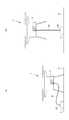
図3は、無人飛行体2の線状部材31の巻き揚げ制御を示す模式図である。なお、図3において、落下防止機構4等の構成は省略されている。
図3の(a)に示すように、無人飛行体2が着陸した状態において、巻き揚げ制御部62は、巻揚機3により線状部材31を解放し、線状部材31を繰り出した状態にする。そして、荷物Tは、無人飛行体2が着陸し、かつ線状部材31の先端が無人飛行体2の本体部分から離間した状態において、線状部材31に接続される。FIG. 3 is a schematic view showing hoisting control of the
As shown in FIG. 3A, when the
線状部材31を解放した状態で無人飛行体2を上昇させることで、荷物Tが線状部材31に引っ張られにくくなり、無人飛行体システム1は、荷物Tへの衝撃(例えば荷物Tが倒れたり、引きずられたりする等)を抑制することができる。 By raising the
なお、線状部材31の解放は、例えば、巻揚機3が線状部材31を巻き取っている巻き筒の回転の固定を解除し、線状部材31が引っ張られると、その引張力により線状部材31が引き出されるような状態のことである。即ち、線状部材31を巻揚機3から引き出し可能な状態である。 To release the
飛行制御部61は、線状部材31に係留された荷物Tが地面Gに配置された状態において無人飛行体2を離陸させる。 The flight control unit 61 takes off the
その後、図3の(b)に示すように、無人飛行体2が離陸した後に、無人飛行体2が荷物Tのほぼ真上に位置するときに、巻き揚げ制御部62は、巻揚機3により線状部材31を巻き揚げさせる。即ち、巻き揚げ制御部62は、無人飛行体2が離陸した後に、線状部材31を巻き揚げ可能な状態を示す巻き揚げ条件が満たされた場合に、巻揚機3により線状部材31を巻き揚げさせる。 After that, as shown in FIG. 3B, when the
また、巻き揚げ制御部62は、無人飛行体2が離陸してから巻き揚げ条件が満たされるまで、巻揚機3により線状部材31を繰り出させる。これにより、無人飛行体2は、線状部材31に係留された荷物Tの位置及び向きを変えずに飛行することができる。 Further, the hoisting
巻き揚げ制御部62において、巻き揚げ条件は、位置関係算出部63により算出された位置関係が線状部材31を巻き揚げ可能な状態であることを含む。ここで、巻揚げ可能な状態は、巻き揚げ制御部62によって荷物Tの真上であると判定された位置であってもよい。 In the
そして、位置関係算出部63は、検知部としての撮像部5、高度計7及び測定部33により検知された位置関係算出情報に基づいて無人飛行体2と荷物Tとの位置関係を算出する。 Then, the positional
例えば、検知部が撮像部5である場合、撮像部5は、位置関係を算出するための位置関係算出情報として荷物Tを含む画像を撮像する。即ち、撮像部5は、画像を位置関係算出情報として検知する。位置関係算出部63は、撮像部5により撮像された荷物Tを含む画像に基づいて無人飛行体2と荷物Tとの位置関係を算出する。 For example, when the detection unit is the
位置関係算出部63は、荷物Tを含む画像から荷物Tを識別し、識別した荷物Tの外形及び大きさを算出する。位置関係算出部63は、記憶部9に予め記憶された荷物Tの外形及び大きさと、荷物Tを含む画像から算出した荷物Tの外形及び大きさとを比較することにより、無人飛行体2と荷物Tとの距離を算出する。また、位置関係算出部63は、荷物Tを含む画像から荷物Tの中心座標を算出する。 The positional
この場合、巻き揚げ制御部62は、位置関係算出部63により算出された無人飛行体2と荷物Tとの距離及び荷物Tの中心座標に基づいて、無人飛行体2の位置が線状部材31を巻き揚げ可能な状態である(荷物Tと無人飛行体2との位置関係は、線状部材31を巻き揚げ可能な状態である)か否かを判定する。 In this case, the hoisting
例えば、巻き揚げ制御部62は、無人飛行体2と荷物Tとの距離が十分離れており、かつ荷物Tの中心座標が無人飛行体2の中心座標から一定範囲内にある場合、線状部材31を巻き揚げ可能な状態であると判定する。ここで、無人飛行体2の中心座標は、例えば、GPSによって検知される。これにより、無人飛行体2が荷物Tのほぼ真上に位置するとき、巻き揚げ制御部62は、線状部材31を巻き揚げ可能な状態であると判定することができる。
本実施形態では、巻揚げ状態を判定するための荷物Tの中心座標と無人飛行体2の中心座標の比較処理は、水平方向における2次元座標を用いて行う。なお、無人飛行体2の中心座標を三次元座標として処理し、上述の一定範囲内にあるか否かを判定する処理のときに座標の水平成分のみを比較に用いる処理でもよい。For example, the hoisting
In the present embodiment, the comparison process between the center coordinates of the luggage T and the center coordinates of the
また、検知部が測定部33及び高度計7である場合、測定部33は、線状部材31の繰り出し長さを測定し、高度計7は、無人飛行体の高度を測定することにより、位置関係算出情報を検知する。位置関係算出部63は、測定部33により測定された線状部材31の繰り出し長さ及び高度計7により測定された無人飛行体2の高度に基づいて位置関係を算出する。 When the detection unit is the measurement unit 33 and the
例えば、位置関係算出部63は、測定部33により測定された線状部材31の繰り出し長さから無人飛行体2と荷物Tとの距離を算出する。
巻き揚げ制御部62は、無人飛行体2と荷物Tとの距離が十分離れており、かつ無人飛行体2と荷物Tとの距離と無人飛行体2の地表からの高度とが一致する場合、線状部材31を巻き揚げ可能な状態であると判定する。これにより、無人飛行体2が荷物Tのほぼ真上に位置するとき、巻き揚げ制御部62は、線状部材31を巻き揚げ可能な状態であると判定することができる。For example, the positional
When the
また、飛行制御部61は、無人飛行体2が離陸してから巻き揚げ条件が満たされるまで、検知部としての撮像部5、高度計7及び測定部33により検知された無人飛行体2と荷物Tとの位置関係に基づいて無人飛行体2の飛行を制御する。 Further, the flight control unit 61 includes the
具体的には、飛行制御部61は、離陸した後、上昇し、巻き揚げ条件が満たされるまで、荷物Tのほぼ真下の位置へ移動するように無人飛行体2の飛行を制御する。そして、巻き揚げ条件を満たし、線状部材31を巻き揚げた後、飛行制御部61は、目標地点へ向かって飛行するように無人飛行体2を制御する。 Specifically, the flight control unit 61 controls the flight of the
また、上述した実施形態に替えて、無人飛行体システム1は、上述したような検知部として撮像部5を用いた構成と、検知部として高度計7及び測定部33を用いた構成とを組み合わせて用いてもよい。 Further, instead of the above-described embodiment, the
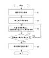
図4は、無人飛行体システム1の制御装置6の処理を示すフローチャートである。
ステップS1において、巻き揚げ制御部62は、無人飛行体2が着陸した状態において巻揚機3により線状部材31を解放させる。そして、荷物Tは、接続部材32により線状部材31に取り付けられる。また、荷物Tの接続部材32への取り付けは、制御装置6に内蔵されるタイマ、ユーザによる遠隔制御装置の操作等によって検知されてもよい。荷物Tの接続部材32への取り付けは、人によって行われてもよく、自動的な制御によって行われてもよい。FIG. 4 is a flowchart showing the processing of the
In step S1, the hoisting
ステップS2において、飛行制御部61は、無人飛行体2を地面Gから離陸させる。飛行制御部61は、例えば荷物Tの接続部材32への取り付けを検知したことに基づいて無人飛行体2を地面Gから離陸させる。 In step S2, the flight control unit 61 takes off the
ステップS3において、位置関係算出部63は、検知部としての撮像部5、高度計7及び測定部33により検知された位置関係算出情報に基づいて無人飛行体2と荷物Tとの位置関係を算出し、飛行制御部61は、位置関係に基づいて無人飛行体2の飛行を制御する。 In step S3, the positional
ステップS4において、巻き揚げ制御部62は、算出された位置関係が巻き揚げ条件を満たすか否かを判定する。上述の巻き揚げ条件を満たす場合(YES)には、ステップS5へ移り、巻き揚げ条件を満たさない場合(NO)には、ステップS3へ戻る。 In step S4, the hoisting
ステップS5において、巻き揚げ制御部62は、巻揚機3に線状部材31を巻き揚げさせる。また、巻き揚げ制御部62は、荷物Tが無人飛行体2から一定範囲内に近付くまで線状部材31を十分に巻き揚げた後、落下防止機構4の可動支持体41を制御して、荷物Tの落下を防止する状態に遷移させる。 In step S5, the hoisting
<第1変形例>
図5は、第1変形例の無人飛行体システム1の構成を示す模式図である。図5に示すように、第1変形例の無人飛行体システム1は、荷物Tを地面Gに対して固定及び解放可能な保持装置10を更に備える。<First modification>
FIG. 5 is a schematic view showing the configuration of the unmanned
保持装置10は、地面Gに設置され、制御装置6又は遠隔制御装置と無線通信することにより制御される。保持装置10は、任意の手段で荷物Tを固定及び解放可能であり、例えば、機械的、電気的又は電磁気的な構成を用いて荷物Tを固定及び解放する。なお、保持装置10による荷物Tの地面Gに対する固定は、必ずしも荷物Tが地面Gに接する必要があるわけではなく、荷物Tと地面Gとの相対的な位置及び姿勢の関係が固定される関係も含む。 The holding
保持装置10は、無人飛行体2が地面Gに着陸した状態で荷物Tを固定する。飛行制御部61は、保持装置10により荷物Tを固定した状態において無人飛行体2を離陸させる。 The holding
その後、上述したように、無人飛行体2が離陸した後に、巻き揚げ制御部62が、線状部材31を巻き揚げ可能な状態を示す巻き揚げ条件が満たされたと判定した場合に、保持装置10は、荷物Tの固定を解放する。そして、巻き揚げ制御部62は、巻き揚げ条件を満たすと、巻揚機3により線状部材31を巻き揚げさせる。 After that, as described above, when the hoisting
なお、無人飛行体システム1は、線状部材31を解放しない(線状部材31の繰り出し長さが固定された)状態において無人飛行体2を離陸させてもよい。荷物Tと線状部材31の繰り出し長とが固定された状態で無人飛行体2を上昇させると、無人飛行体2は、荷物Tの真上に移動する。 The
即ち、線状部材31が緊張した状態において、無人飛行体2に掛かる力は、回転翼21による垂直上方向の力と、線状部材31による荷物方向の力との合力となり、当該合力に従って無人飛行体2は移動する。 That is, in a state where the
無人飛行体2の移動の結果、最終的にそれら2つの力が逆方向で拮抗した状態になると、無人飛行体2は、空中でほぼ停止する。拮抗した状態において、2つの力が逆方向であるため、荷物Tは、無人飛行体2から見て垂直上方向とは逆方向に存在する、即ち無人飛行体2は、荷物Tの真上に存在する。 As a result of the movement of the
したがって、無人飛行体システム1は、荷物Tと無人飛行体2との位置関係を直接的に計測しなくても(例えば十分な時間上昇させたか否かに基づいて)巻き揚げ状態が満たされたか否かを判定することができる。 Therefore, has the
また、線状部材31を解放して、無人飛行体2を上昇させた場合であっても、巻揚機3の巻き筒の回転抵抗が0でない限り、荷物Tに対してわずかに力が掛かる。そのため、荷物が軽い場合には、荷物が倒れたり引きずられたりする可能性がある。しかし、本変形例のように荷物を固定した状態で無人飛行体を上昇させることで、その間に荷物に与えられる衝撃(例えば、倒れる、引きずられる等)をより抑制することができる。そのため、本変形例の無人飛行体システム1は、例えば軽く、かつできるだけ衝撃を与えたくない荷物(例えばコップに入った飲料等)を運ぶ場合、より好適である。 Further, even when the
<第2変形例>
図6は、第2変形例の無人飛行体システム1の構成を示す模式図である。図6に示すように、第2変形例の無人飛行体システム1は、高度計7を備え、巻き揚げ制御部62は、高度計7により測定された無人飛行体2の高度に応じて、巻揚機3により線状部材31を繰り出させる。<Second modification>
FIG. 6 is a schematic view showing the configuration of the unmanned
具体的には、図6の(a)に示すように、無人飛行体2の高度が低い場合、巻き揚げ制御部62は、巻揚機3により無人飛行体2の高度に応じた長さの線状部材31を繰り出させる。
そして、図6の(b)に示すように、図6の(a)よりも無人飛行体2の高度が高い場合、巻き揚げ制御部62は、巻揚機3により更に線状部材31を繰り出させる。Specifically, as shown in FIG. 6A, when the altitude of the
Then, as shown in FIG. 6B, when the altitude of the
即ち、上述した実施形態では、巻き揚げ制御部62は、無人飛行体2が離陸してから巻き揚げ条件が満たされるまで、巻揚機3により線状部材31を解放させたが、変形例1では、巻き揚げ制御部62は、巻揚機3により線状部材31を解放させず、無人飛行体2の高度に応じて、巻揚機3により線状部材31を繰り出させる。 That is, in the above-described embodiment, the hoisting
なお、上述した実施形態では、制御装置6は、無人飛行体2の内部に設けられてたが、制御装置6は、無人飛行体2から離間した場所に設けられ、無線通信を用いて無人飛行体2を遠隔制御してもよい。 In the above-described embodiment, the
以上の説明から明らかなように、本発明の各実施形態は、以下の各構成により、それぞれ有利な効果を奏する。 As is clear from the above description, each embodiment of the present invention exerts an advantageous effect by each of the following configurations.
本発明の実施形態に係る無人飛行体システム(1)は、線状部材(31)の繰り出し及び巻き揚げが可能な巻揚機を備えた無人飛行体(2)と、線状部材(31)に係留された荷物(T)が地面(G)に配置された状態において無人飛行体(2)を離陸させる飛行制御部(61)と、無人飛行体(2)が離陸した後に、線状部材31を巻き揚げ可能な状態を示す巻き揚げ条件が満たされた場合に、巻揚機(3)により線状部材(31)を巻き揚げさせる巻き揚げ制御部(62)と、を含む。 The unmanned air vehicle system (1) according to the embodiment of the present invention includes an unmanned air vehicle (2) provided with a hoist capable of feeding and hoisting a linear member (31), and a linear member (31). A flight control unit (61) that takes off the unmanned aircraft (2) while the luggage (T) moored in the aircraft is placed on the ground (G), and a linear member after the unmanned aircraft (2) takes off. A hoisting control unit (62) for hoisting the linear member (31) by the hoisting machine (3) when the hoisting condition indicating a state in which the 31 can be hoisted is satisfied is included.
これにより、無人飛行体システム(1)は、無人飛行体(2)が着陸した状態では、巻揚機(3)により線状部材(31)を巻き揚げていないため、ユーザは、無人飛行体(2)の本体部分から離れた場所で、より容易に荷物(T)を線状部材(31)に係留することができる。 As a result, in the unmanned air vehicle system (1), when the unmanned air vehicle (2) is landed, the linear member (31) is not unwound by the hoist (3), so that the user can use the unmanned air vehicle. The luggage (T) can be more easily moored to the linear member (31) at a place away from the main body portion of (2).
また、巻き揚げ制御部(62)は、無人飛行体(2)が離陸してから巻き揚げ条件が満たされるまで、巻揚機(3)から引き出し可能に線状部材(31)を解放させる。これにより、無人飛行体システム(1)は、線状部材(31)に係留された荷物(T)の位置及び向きを変えずに無人飛行体(2)を飛行させることができる。 Further, the hoisting control unit (62) releases the linear member (31) so that it can be pulled out from the hoisting machine (3) after the unmanned vehicle (2) takes off until the hoisting condition is satisfied. As a result, the unmanned vehicle system (1) can fly the unmanned vehicle (2) without changing the position and orientation of the luggage (T) moored to the linear member (31).
また、巻き上げ条件は、位置関係算出部63により算出された位置関係が線状部材31を巻き揚げ可能な状態であることを含む。これにより、無人飛行体システム(1)は、線状部材(31)を巻き揚げ可能な位置から適切に線状部材(31)を巻き揚げることができる。 Further, the winding condition includes that the positional relationship calculated by the positional
また、線状部材(31)を巻き揚げ可能な状態は、巻き揚げ制御部(62)により荷物(T)の真上であると判定された位置である。これにより、無人飛行体システム(1)は、無人飛行体(2)が荷物(T)の真上にあるときに、線状部材(31)を巻き揚げることができる。 Further, the state in which the linear member (31) can be unwound is a position determined by the unwinding control unit (62) to be directly above the load (T). Thereby, the unmanned vehicle system (1) can wind up the linear member (31) when the unmanned vehicle (2) is directly above the cargo (T).
また、位置関係算出部(63)は、撮像部(5)により撮像された荷物(T)を含む画像に基づいて無人飛行体(2)と荷物(T)との位置関係を算出する。これにより、無人飛行体システム(1)は、撮像された荷物(T)を含む画像を用いて、適切に無人飛行体(2)と荷物(T)との位置関係を算出することができる。 Further, the positional relationship calculation unit (63) calculates the positional relationship between the unmanned aircraft (2) and the luggage (T) based on the image including the luggage (T) captured by the imaging unit (5). Thereby, the unmanned vehicle system (1) can appropriately calculate the positional relationship between the unmanned vehicle (2) and the luggage (T) by using the image including the captured luggage (T).
また、位置関係算出部(63)は、測定部(33)により測定された線状部材(31)の繰り出し長さ及び高度計(7)により測定された無人飛行体(2)の高度に基づいて位置関係を算出する。これにより、無人飛行体システム(1)は、線状部材(31)の繰り出し長さ及び無人飛行体(2)の高度を用いて、適切に無人飛行体(2)と荷物(T)との位置関係を算出することができる。 Further, the positional relationship calculation unit (63) is based on the extension length of the linear member (31) measured by the measurement unit (33) and the altitude of the unmanned vehicle (2) measured by the altimeter (7). Calculate the positional relationship. As a result, the unmanned vehicle system (1) appropriately connects the unmanned vehicle (2) and the luggage (T) by using the feeding length of the linear member (31) and the altitude of the unmanned vehicle (2). The positional relationship can be calculated.
また、飛行制御部(61)は、無人飛行体(2)が離陸してから巻き揚げ条件が満たされるまで、検知部(5,7,33)により検知された無人飛行体(2)と荷物(T)との位置関係に基づいて無人飛行体(2)の飛行を制御する。これにより、無人飛行体システム(1)は、線状部材(31)及び荷物(T)の状態に応じて無人飛行体2を飛行させることができる。 Further, the flight control unit (61) includes the unmanned aircraft (2) and the luggage detected by the detection unit (5,7,33) from the time the unmanned aircraft (2) takes off until the hoisting condition is satisfied. The flight of the unmanned flying object (2) is controlled based on the positional relationship with (T). As a result, the unmanned vehicle system (1) can fly the
また、無人飛行体システム(1)は、荷物(T)を地面に対して固定及び解放可能な保持装置(10)を更に含み、飛行制御部(61)は、保持装置(10)により荷物(T)を固定した状態において無人飛行体(2)を離陸させる。これにより、無人飛行体(2)は、線状部材(31)に係留された荷物(T)の位置及び向きを変えずに飛行し、線状部材(31)を巻き揚げることができる。したがって、線状部材(31)を巻き揚げる前に荷物(T)が倒れたりする事態の発生を確実に防止できる。 Further, the unmanned vehicle system (1) further includes a holding device (10) capable of fixing and releasing the luggage (T) to the ground, and the flight control unit (61) is provided with the luggage (10) by the holding device (10). Take off the unmanned aircraft (2) with T) fixed. As a result, the unmanned vehicle (2) can fly without changing the position and orientation of the luggage (T) moored to the linear member (31), and can wind up the linear member (31). Therefore, it is possible to reliably prevent the occurrence of a situation in which the luggage (T) falls before the linear member (31) is unwound.
また、飛行制御部(61)は、線状部材(31)を解放しない状態において無人飛行体(2)を離陸させる。これにより、無人飛行体システム(1)は、例えば軽く、かつできるだけ衝撃を与えたくない荷物T(例えばコップに入った飲料等)を運ぶ場合、より好適である。 Further, the flight control unit (61) takes off the unmanned flying object (2) without releasing the linear member (31). As a result, the unmanned vehicle system (1) is more suitable for carrying a luggage T (for example, a beverage in a glass) that is light and does not want to be impacted as much as possible.
また、無人飛行体システム(1)は、無人飛行体(2)の高度を測定する高度計(7)を更に含み、巻き揚げ制御部(62)は、高度計(7)により測定された無人飛行体(2)の高度に応じて、巻揚機(3)により線状部材を繰り出させる。これにより、無人飛行体システム(1)は、線状部材(31)に係留された荷物(T)の位置及び向きを変えずに飛行し、線状部材(31)を巻き揚げることができる。 Further, the unmanned air vehicle system (1) further includes an altimeter (7) for measuring the altitude of the unmanned air vehicle (2), and the hoisting control unit (62) is an unmanned air vehicle measured by the altimeter (7). The linear member is unwound by the hoisting machine (3) according to the altitude of (2). As a result, the unmanned vehicle system (1) can fly without changing the position and orientation of the luggage (T) moored to the linear member (31), and can wind up the linear member (31).
本発明の実施形態に係る無人飛行体(2)の制御装置(6)は、線状部材(31)に係留された荷物(T)が地面(G)に配置された状態において無人飛行体(2)を離陸させる飛行制御部(61)と、無人飛行体(2)が離陸した後に、線状部材(31)を巻き揚げ可能な状態を示す巻き揚げ条件が満たされた場合に、巻揚機(3)により線状部材(31)を巻き揚げさせる巻き揚げ制御部(62)と、を含む。これにより、制御装置(6)は、無人飛行体(2)が着陸した状態では、巻揚機(3)により線状部材(31)を巻き揚げていないため、ユーザは、より容易に荷物(T)を線状部材(31)に係留することができる。 The control device (6) of the unmanned aircraft (2) according to the embodiment of the present invention is an unmanned aircraft (6) in a state where the luggage (T) moored to the linear member (31) is placed on the ground (G). When the flight control unit (61) for taking off 2) and the unmanned vehicle (2) take off and the hoisting condition indicating a state in which the linear member (31) can be hoisted is satisfied, the hoisting is performed. It includes a hoisting control unit (62) for hoisting a linear member (31) by a machine (3). As a result, the control device (6) does not unwind the linear member (31) by the hoist (3) when the unmanned air vehicle (2) has landed, so that the user can more easily carry the luggage ( T) can be moored to the linear member (31).
本発明の実施形態に係る無人飛行体(2)の制御方法は、線状部材(31)に係留された荷物(T)が地面に配置された状態において無人飛行体(2)を離陸させるステップと、無人飛行体(2)が離陸した後に、線状部材(31)を巻き揚げ可能な状態を示す巻き揚げ条件が満たされた場合に、巻揚機(3)により線状部材(31)を巻き揚げさせるステップと、を含む。 The control method of the unmanned air vehicle (2) according to the embodiment of the present invention is a step of taking off the unmanned air vehicle (2) in a state where the luggage (T) moored to the linear member (31) is placed on the ground. After the unmanned aircraft (2) has taken off, when the hoisting condition indicating a state in which the linear member (31) can be unwound is satisfied, the linear member (31) is operated by the hoisting machine (3). Includes steps to unwind and.
1 無人飛行体システム
2 無人飛行体
3 巻揚機
31 線状部材
32 接続部材
33 測定部
4 落下防止機構
41 可動支持体
5 撮像部
6 制御装置
61 飛行制御部
62 巻き揚げ制御部
63 位置関係算出部
7 高度計
8 通信部
9 記憶部
10 固定装置
21 回転翼
22 モータ
T 荷物1
Claims (6)
Translated fromJapanese無人飛行体の制御方法。A step of taking off an unmanned aircraft with a load moored to a linear member placed on the ground,and a step of detecting positional relationship calculation information for calculating the positional relationship between the unmanned aircraft and the load.Indicates a step of calculating the positional relationship between the unmanned aircraft and the luggage based onthe detected positional relationship calculation information, and a state in which the linear member can be hoisted after the unmanned aircraft takes off. when the winding fried condition issatisfied,is wound fried the linear member bywinch, until said unmanned aircraft is the take-fried condition after takeoff is satisfied, withdrawable from said winchlook including the stepsof: to release the linearmember,the winding up condition includes that the positional relationship calculated is wound fried ready the linear member,wound fried enables the linear member The state is a position determined by the hoisting control unit to be directly above the load, and in thestep of hoisting the linear member by the hoisting machine, the unmanned flying object is defined as the positional relationship. Based on the distance between the and the luggage, it is determined whether or not the linear member can be wound up.
How to control an unmanned aircraft.
Applications Claiming Priority (1)
| Application Number | Priority Date | Filing Date | Title |
|---|---|---|---|
| PCT/JP2019/044928WO2021095249A1 (en) | 2019-11-15 | 2019-11-15 | Unmanned aerial vehicle system, control device and control method |
Publications (2)
| Publication Number | Publication Date |
|---|---|
| JP6945764B1true JP6945764B1 (en) | 2021-10-06 |
| JPWO2021095249A1 JPWO2021095249A1 (en) | 2021-11-25 |
Family
ID=75912097
Family Applications (1)
| Application Number | Title | Priority Date | Filing Date |
|---|---|---|---|
| JP2021516702AActiveJP6945764B1 (en) | 2019-11-15 | 2019-11-15 | Unmanned aircraft system, control device and control method |
Country Status (5)
| Country | Link |
|---|---|
| US (1) | US12179922B2 (en) |
| EP (1) | EP3885259B1 (en) |
| JP (1) | JP6945764B1 (en) |
| CN (1) | CN113226927B (en) |
| WO (1) | WO2021095249A1 (en) |
Families Citing this family (6)
| Publication number | Priority date | Publication date | Assignee | Title |
|---|---|---|---|---|
| US11530041B2 (en)* | 2020-06-03 | 2022-12-20 | Inventus Holdings, Llc | Multi-bay drone for removing and replacing a device in a device receptacle in a single visit |
| JP2023026855A (en)* | 2021-08-16 | 2023-03-01 | 日鉄テックスエンジ株式会社 | Moving work device and work method using moving work device |
| JP7427052B1 (en) | 2022-07-28 | 2024-02-02 | 楽天グループ株式会社 | Control device, unmanned aircraft, and control method |
| WO2024180628A1 (en)* | 2023-02-27 | 2024-09-06 | 株式会社アイ・ロボティクス | Mobile work apparatus and work method using mobile work apparatus |
| CN116588845A (en)* | 2023-05-11 | 2023-08-15 | 北京科技大学 | Winch action control device, unmanned aerial vehicle undercarriage and unmanned aerial vehicle |
| US12119626B1 (en)* | 2024-03-09 | 2024-10-15 | Henry Hardy Perritt, Jr. | System and method for lifting lines over a support using a drone |
Citations (6)
| Publication number | Priority date | Publication date | Assignee | Title |
|---|---|---|---|---|
| JPS5422680B1 (en)* | 1969-05-19 | 1979-08-08 | ||
| JP2005263112A (en)* | 2004-03-19 | 2005-09-29 | Chugoku Electric Power Co Inc:The | Carrying method by unmanned flying body |
| US9027879B1 (en)* | 2005-06-13 | 2015-05-12 | Robert N. Talmage, Jr. | Modular adaptive configured helicopter |
| US20170341748A1 (en)* | 2016-05-25 | 2017-11-30 | Airbus Helicopters | Aircraft provided with a winch device |
| JP2018055692A (en)* | 2017-10-17 | 2018-04-05 | 楽天株式会社 | Logistics system, luggage transport method, and program |
| WO2019026346A1 (en)* | 2017-07-31 | 2019-02-07 | ユーピーアール株式会社 | Cargo monitoring system |
Family Cites Families (21)
| Publication number | Priority date | Publication date | Assignee | Title |
|---|---|---|---|---|
| US6086015A (en)* | 1999-05-07 | 2000-07-11 | Aerovironment, Inc. | Aerial transport method and apparatus |
| CN103508354B (en)* | 2013-10-16 | 2015-08-05 | 长沙中联消防机械有限公司 | Method, device and system for controlling falling of sliding bucket of aerial ladder mechanism and aerial work machine |
| JP6384955B2 (en) | 2014-11-04 | 2018-09-05 | ドーンコーラス合同会社 | Delivery method by unmanned air vehicle |
| US20160318609A1 (en)* | 2015-05-01 | 2016-11-03 | Other Lab, Llc | System and method for flying trucks |
| US9969494B1 (en)* | 2015-09-28 | 2018-05-15 | Amazon Technologies, Inc. | Delivery drop platforms, tethers, and stabilization |
| JP6393887B2 (en)* | 2015-11-06 | 2018-09-26 | 株式会社プロドローン | Transport device and transport method |
| US11475390B2 (en)* | 2015-12-29 | 2022-10-18 | Rakuten Group, Inc. | Logistics system, package delivery method, and program |
| CN113342038B (en)* | 2016-02-29 | 2024-08-20 | 星克跃尔株式会社 | Method and system for generating map for unmanned aerial vehicle flight |
| JP2017217942A (en)* | 2016-06-03 | 2017-12-14 | 株式会社衛星ネットワーク | Unmanned aircraft system, unmanned aircraft, mooring device |
| CN107479568A (en)* | 2016-06-08 | 2017-12-15 | 松下电器(美国)知识产权公司 | Unmanned vehicle, control method and control program |
| US10232940B2 (en)* | 2016-09-09 | 2019-03-19 | Wing Aviation Llc | Methods and systems for raising and lowering a payload |
| US10793274B2 (en)* | 2016-09-09 | 2020-10-06 | Wing Aviation Llc | Payload coupling apparatus for UAV and method of delivering a payload |
| US10604252B2 (en)* | 2016-11-22 | 2020-03-31 | Wing Aviation Llc | Landing and payload loading structures |
| CN206671894U (en)* | 2017-04-01 | 2017-11-24 | 高域(北京)智能科技研究院有限公司 | Take off control device and its unmanned vehicle |
| US11853037B2 (en) | 2017-04-17 | 2023-12-26 | Globeride, Inc. | Electric hoisting machine and control device and control method therefor |
| DE102017112765A1 (en)* | 2017-06-09 | 2018-12-13 | Liebherr-Werk Biberach Gmbh | Method and device for lifting a load |
| GB201808075D0 (en)* | 2017-09-13 | 2018-07-04 | Flirtey Holdings Inc | Unmanned aerial vehicle and payload delivery system |
| JP7106160B2 (en)* | 2018-03-27 | 2022-07-26 | 株式会社Acsl | unmanned aerial vehicle |
| US10875648B2 (en)* | 2018-06-11 | 2020-12-29 | Wing Aviation Llc | Loading structure with tether guide for unmanned aerial vehicle |
| CN109866934B (en)* | 2019-02-15 | 2022-07-26 | 广州市石门国家森林公园管理处(广州市大岭山林场) | Helicopter fire pod for forest fire protection |
| GB201907302D0 (en)* | 2019-05-23 | 2019-07-10 | Bmt Defence Services Ltd | Delivery system |
- 2019
- 2019-11-15JPJP2021516702Apatent/JP6945764B1/enactiveActive
- 2019-11-15EPEP19952908.2Apatent/EP3885259B1/enactiveActive
- 2019-11-15CNCN201980085375.3Apatent/CN113226927B/enactiveActive
- 2019-11-15USUS17/417,546patent/US12179922B2/enactiveActive
- 2019-11-15WOPCT/JP2019/044928patent/WO2021095249A1/ennot_activeCeased
Patent Citations (6)
| Publication number | Priority date | Publication date | Assignee | Title |
|---|---|---|---|---|
| JPS5422680B1 (en)* | 1969-05-19 | 1979-08-08 | ||
| JP2005263112A (en)* | 2004-03-19 | 2005-09-29 | Chugoku Electric Power Co Inc:The | Carrying method by unmanned flying body |
| US9027879B1 (en)* | 2005-06-13 | 2015-05-12 | Robert N. Talmage, Jr. | Modular adaptive configured helicopter |
| US20170341748A1 (en)* | 2016-05-25 | 2017-11-30 | Airbus Helicopters | Aircraft provided with a winch device |
| WO2019026346A1 (en)* | 2017-07-31 | 2019-02-07 | ユーピーアール株式会社 | Cargo monitoring system |
| JP2018055692A (en)* | 2017-10-17 | 2018-04-05 | 楽天株式会社 | Logistics system, luggage transport method, and program |
Also Published As
| Publication number | Publication date |
|---|---|
| CN113226927B (en) | 2024-10-29 |
| WO2021095249A1 (en) | 2021-05-20 |
| US20220048621A1 (en) | 2022-02-17 |
| CN113226927A (en) | 2021-08-06 |
| EP3885259A4 (en) | 2022-01-05 |
| JPWO2021095249A1 (en) | 2021-11-25 |
| US12179922B2 (en) | 2024-12-31 |
| EP3885259B1 (en) | 2025-09-10 |
| EP3885259A1 (en) | 2021-09-29 |
Similar Documents
| Publication | Publication Date | Title |
|---|---|---|
| JP6945764B1 (en) | Unmanned aircraft system, control device and control method | |
| AU2021203884B2 (en) | System for mid-air payload retrieval by a UAV | |
| US10450065B2 (en) | Stabilized airborne drop delivery | |
| US12054256B2 (en) | UAV with upper door including winch and method of operation | |
| CN112638770A (en) | Safe unmanned aerial vehicle | |
| US11767111B1 (en) | Slotted receptacle for payload handle to secure payload within a UAV | |
| CN112188981A (en) | Method for unmanned aerial vehicle to automatically pick up package | |
| WO2024015756A1 (en) | Smart cargo bay door(s) for a uav | |
| US12168512B2 (en) | UAV with open cargo bay and method of operation | |
| US11767114B2 (en) | Package retrieval system with funneling mechanism | |
| US20230159167A1 (en) | Package Loading Mechanism | |
| US20230192296A1 (en) | Package Retrieval System with Channel to Engage Payload Retriever | |
| US20240217659A1 (en) | Payload Retrieval Apparatus with Extending Member For Use with a UAV | |
| WO2024254283A1 (en) | Payload retriever having multiple slots for use with a uav | |
| US20240150016A1 (en) | Payload Receiver Apparatus for Use With a UAV | |
| JP7459385B1 (en) | Control device, unmanned aircraft, and control method | |
| CN117465672A (en) | Control device, unmanned aerial vehicle and control method | |
| WO2024145575A1 (en) | Payload retrieval apparatus having tether slot projection for use with a uav |
Legal Events
| Date | Code | Title | Description |
|---|---|---|---|
| A621 | Written request for application examination | Free format text:JAPANESE INTERMEDIATE CODE: A621 Effective date:20210323 | |
| A871 | Explanation of circumstances concerning accelerated examination | Free format text:JAPANESE INTERMEDIATE CODE: A871 Effective date:20210323 | |
| A975 | Report on accelerated examination | Free format text:JAPANESE INTERMEDIATE CODE: A971005 Effective date:20210428 | |
| A131 | Notification of reasons for refusal | Free format text:JAPANESE INTERMEDIATE CODE: A131 Effective date:20210511 | |
| A521 | Request for written amendment filed | Free format text:JAPANESE INTERMEDIATE CODE: A523 Effective date:20210708 | |
| TRDD | Decision of grant or rejection written | ||
| A01 | Written decision to grant a patent or to grant a registration (utility model) | Free format text:JAPANESE INTERMEDIATE CODE: A01 Effective date:20210817 | |
| A61 | First payment of annual fees (during grant procedure) | Free format text:JAPANESE INTERMEDIATE CODE: A61 Effective date:20210914 | |
| R150 | Certificate of patent or registration of utility model | Ref document number:6945764 Country of ref document:JP Free format text:JAPANESE INTERMEDIATE CODE: R150 |