JP6940698B2 - Input device - Google Patents
Input deviceDownload PDFInfo
- Publication number
- JP6940698B2 JP6940698B2JP2020519477AJP2020519477AJP6940698B2JP 6940698 B2JP6940698 B2JP 6940698B2JP 2020519477 AJP2020519477 AJP 2020519477AJP 2020519477 AJP2020519477 AJP 2020519477AJP 6940698 B2JP6940698 B2JP 6940698B2
- Authority
- JP
- Japan
- Prior art keywords
- sensor
- panel member
- operation panel
- input device
- point
- Prior art date
- Legal status (The legal status is an assumption and is not a legal conclusion. Google has not performed a legal analysis and makes no representation as to the accuracy of the status listed.)
- Active
Links
Images


Classifications
- G—PHYSICS
- G06—COMPUTING OR CALCULATING; COUNTING
- G06F—ELECTRIC DIGITAL DATA PROCESSING
- G06F3/00—Input arrangements for transferring data to be processed into a form capable of being handled by the computer; Output arrangements for transferring data from processing unit to output unit, e.g. interface arrangements
- G06F3/01—Input arrangements or combined input and output arrangements for interaction between user and computer
- G06F3/016—Input arrangements with force or tactile feedback as computer generated output to the user
- G—PHYSICS
- G06—COMPUTING OR CALCULATING; COUNTING
- G06F—ELECTRIC DIGITAL DATA PROCESSING
- G06F3/00—Input arrangements for transferring data to be processed into a form capable of being handled by the computer; Output arrangements for transferring data from processing unit to output unit, e.g. interface arrangements
- G06F3/01—Input arrangements or combined input and output arrangements for interaction between user and computer
- G06F3/03—Arrangements for converting the position or the displacement of a member into a coded form
- G06F3/033—Pointing devices displaced or positioned by the user, e.g. mice, trackballs, pens or joysticks; Accessories therefor
- G06F3/0354—Pointing devices displaced or positioned by the user, e.g. mice, trackballs, pens or joysticks; Accessories therefor with detection of 2D relative movements between the device, or an operating part thereof, and a plane or surface, e.g. 2D mice, trackballs, pens or pucks
- G06F3/03547—Touch pads, in which fingers can move on a surface
- G—PHYSICS
- G06—COMPUTING OR CALCULATING; COUNTING
- G06F—ELECTRIC DIGITAL DATA PROCESSING
- G06F3/00—Input arrangements for transferring data to be processed into a form capable of being handled by the computer; Output arrangements for transferring data from processing unit to output unit, e.g. interface arrangements
- G06F3/01—Input arrangements or combined input and output arrangements for interaction between user and computer
- G06F3/03—Arrangements for converting the position or the displacement of a member into a coded form
- G06F3/041—Digitisers, e.g. for touch screens or touch pads, characterised by the transducing means
- G06F3/0414—Digitisers, e.g. for touch screens or touch pads, characterised by the transducing means using force sensing means to determine a position
- G—PHYSICS
- G06—COMPUTING OR CALCULATING; COUNTING
- G06F—ELECTRIC DIGITAL DATA PROCESSING
- G06F3/00—Input arrangements for transferring data to be processed into a form capable of being handled by the computer; Output arrangements for transferring data from processing unit to output unit, e.g. interface arrangements
- G06F3/01—Input arrangements or combined input and output arrangements for interaction between user and computer
- G06F3/03—Arrangements for converting the position or the displacement of a member into a coded form
- G06F3/041—Digitisers, e.g. for touch screens or touch pads, characterised by the transducing means
- G06F3/042—Digitisers, e.g. for touch screens or touch pads, characterised by the transducing means by opto-electronic means
Landscapes
- Engineering & Computer Science (AREA)
- General Engineering & Computer Science (AREA)
- Theoretical Computer Science (AREA)
- Human Computer Interaction (AREA)
- Physics & Mathematics (AREA)
- General Physics & Mathematics (AREA)
- Position Input By Displaying (AREA)
- User Interface Of Digital Computer (AREA)
Description
Translated fromJapanese本開示は、入力装置に関する。 The present disclosure relates to an input device.
タッチパッドに加えられた圧力を検出できる入力装置が知られている。 Input devices that can detect the pressure applied to the touchpad are known.
例えば、下記特許文献1には、タッチパッドを押圧している力を検出する圧電センサをタッチパッドの隅部に設け、各圧電センサから出力された信号から圧力を算出する入力装置が記載されている。 For example,
しかしながら、押圧に対して沈み込みが許容され、押し込み量に応じた操作方法、操作触感を提供するようなタッチパッドにおいて、特許文献1に記載の入力装置では、操作位置の押し込み量、つまり変位量を高精度で検出することができない。 However, in a touch pad that allows sinking with respect to pressing and provides an operation method and an operation tactile sensation according to the pressing amount, in the input device described in
本開示は、操作位置の変位量を高精度で検出することができる入力装置を提供することを目的とする An object of the present disclosure is to provide an input device capable of detecting a displacement amount of an operating position with high accuracy.
入力装置の一態様は、入力操作面を有し、当該入力操作面内の操作位置の座標を検出する操作パネル部材と、前記操作パネル部材から離間した基準面内に配置され、それぞれが前記操作パネル部材との間の距離を検出する第1のセンサ、第2のセンサ及び第3のセンサと、前記操作パネル部材及び前記第1のセンサ、前記第2のセンサ及び前記第3のセンサからの信号を処理する信号処理装置と、を有し、前記操作パネル部材は、前記操作位置に加えられた荷重に応じて前記基準面に対して傾斜可能であり、前記信号処理装置は、前記操作パネル部材が検出した前記入力操作面内の前記操作位置の座標並びに前記第1のセンサ、前記第2のセンサ及び前記第3のセンサが検出したそれぞれの距離から前記操作位置における前記操作パネル部材の操作前後での変位量を算出する。 One aspect of the input device is an operation panel member having an input operation surface and detecting coordinates of an operation position in the input operation surface, and an operation panel member arranged in a reference surface separated from the operation panel member, and each of them operates. From the first sensor, the second sensor and the third sensor for detecting the distance between the panel members, the operation panel member and the first sensor, the second sensor and the third sensor. The operation panel member includes a signal processing device for processing a signal, and the operation panel member can be tilted with respect to the reference plane according to a load applied to the operation position, and the signal processing device is the operation panel. Operation of the operation panel member at the operation position from the coordinates of the operation position in the input operation surface detected by the member and the respective distances detected by the first sensor, the second sensor, and the third sensor. Calculate the amount of displacement before and after.
本開示によれば、操作位置の変位量を高精度で検出することができる。 According to the present disclosure, the displacement amount of the operating position can be detected with high accuracy.
以下、本開示の実施形態について添付の図面を参照しながら具体的に説明する。なお、本明細書及び図面において、実質的に同一の機能構成を有する構成要素については、同一の符号を付することにより重複した説明を省くことがある。 Hereinafter, embodiments of the present disclosure will be specifically described with reference to the accompanying drawings. In the present specification and the drawings, components having substantially the same functional configuration may be designated by the same reference numerals to omit duplicate explanations.
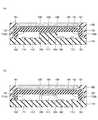
図1は、実施形態に係る入力装置の構成を示す斜視図であり、図2は、実施形態に係る入力装置の構成を示す上面図であり、図3は、実施形態に係る入力装置の構成を示す断面図である。図3(a)は図2中のI−I線に沿った断面図に相当し、図3(b)は図2中のII−II線に沿った断面図に相当する。 FIG. 1 is a perspective view showing the configuration of the input device according to the embodiment, FIG. 2 is a top view showing the configuration of the input device according to the embodiment, and FIG. 3 is a configuration of the input device according to the embodiment. It is a cross-sectional view which shows. FIG. 3A corresponds to a cross-sectional view taken along line I-I in FIG. 2, and FIG. 3B corresponds to a cross-sectional view taken along line II-II in FIG.
図1〜図3に示すように、実施形態に係る入力装置100は、固定ベース110、固定ベース110の縁上に固定されたベゼル120、及びベゼル120の内側の化粧パネル150を有する。化粧パネル150の固定ベース110側にタッチパッド140が設けられており、タッチパッド140の固定ベース110側に可動ベース130が設けられている。可動ベース130は、平面視でタッチパッド140及び化粧パネル150より広い平板部131、及び平板部131の縁から固定ベース110に向かって延びる壁部132を有する。固定ベース110は、平面視で中央に凸部111を有し、凸部111上にアクチュエータ160が設けられている。アクチュエータ160は凸部111及び平板部131に接触する。タッチパッド140はタッチパッド部の一例であり、可動ベース130はタッチパッド140を保持する保持部の一例であり、タッチパッド140及び可動ベース130が操作パネル部材に含まれる。固定ベース110は支持部材の一例である。 As shown in FIGS. 1 to 3, the
壁部132と固定ベース110との間に、壁部132及び固定ベース110に接触する複数のラバー192が設けられている。ラバー192は、平面視で少なくとも一つの三角形を構成するように配置されている。例えば、ラバー192は、平面視でタッチパッド140の四隅の周囲に配置されている。 A plurality of
平板部131とベゼル120との間に、平板部131及びベゼル120に接触する複数のラバー191が設けられている。ラバー191は、平面視で少なくとも一つの三角形を構成するように配置されている。例えば、ラバー191は、平面視でラバー192と重なるようにして、タッチパッド140の四隅の周囲に配置されている。 A plurality of
凸部111と平板部131との間に、凸部111及び平板部131に接触する複数のラバー193が設けられている。ラバー193は、平面視で少なくとも一つの三角形を構成するようにアクチュエータ160の周囲に配置されている。例えば、ラバー193は、タッチパッド140の四辺の各々とアクチュエータ160との間(平面視でラバー191及びラバー192よりもタッチパッド140の中央側)に3か所ずつ配置されている。 A plurality of
例えば、ラバー193はラバー191及びラバー192よりも硬く、ラバー191及びラバー192は互いに同程度の硬さを有する。ラバー191及びラバー192は第1の弾性部材の一例であり、ラバー193は第2の弾性部材の一例である。弾性部材を介して平板部131が支持されるので、タッチパッド140の入力操作面は傾斜可能である。 For example,
また、固定ベース110上に複数の反射型のフォトインタラプタ171、172、173及び174が設けられている。フォトインタラプタ171〜174は、その上方にある可動ベース130の平板部131の点171A〜174Aに光を照射し、平板部131により反射された光を受光して、平板部131の光が照射された部分までの距離を検出することができる。例えば、フォトインタラプタ171〜174は、平面視でタッチパッド140の四隅の内側に配置されている。従って、フォトインタラプタ171〜174は、平面視で少なくとも一つの三角形を構成する。フォトインタラプタ171〜174は第1〜第4のセンサ(フォトセンサ)の一例であり、固定ベース110のフォトインタラプタ171〜174が設けられた面112は基準面の一例である。基準面は操作パネル部材(可動ベース130等)から離間している。本実施形態では、基準面をX軸及びY軸を含む基準平面、基準面に垂直な方向をZ軸方向(第1の方向)とする。 Further, a plurality of
更に、固定ベース110上に信号処理装置180が設けられている。信号処理装置180は、後述の処理により、タッチパッド140の操作に応じて、アクチュエータ160を駆動させてユーザへの触覚フィードバックを行う。信号処理装置180は、例えば半導体チップである。本実施形態では信号処理装置180が固定ベース110上に設けられているが、信号処理装置180が設けられる場所は限定されず、例えばタッチパッド140と可動ベース130との間等に設けられていてもよい。 Further, a
このように構成された入力装置100の動作の一例では、タッチパッド140が操作されると、その操作位置及び操作荷重に応じてアクチュエータ160がタッチパッド140の入力操作面に垂直の方向に振動する。ユーザは、入力操作面に振動を感じることで、入力装置100等に設けられる表示装置を視認せずとも、入力装置100に対して行った操作がどのように反映されたかを認識することができる。例えば、入力装置100が自動車の各種スイッチ用にセンターコンソールに設けられる場合、運転手は入力装置100に視線を移さずとも自身が行った操作がどのように反映されたかをアクチュエータ160の振動から認識することができる。なお、アクチュエータ160は、上記の例に限らず、任意の方向の振動を発生させる構成であってもよい。 In an example of the operation of the
ここで、本実施形態における処理の基本的原理について説明する。本実施形態では、各フォトインタラプタ171〜174により検出される平板部131までの距離及びタッチパッド140により検出される操作位置の座標から平板部131についての平面の方程式、つまり点171A〜174Aを含む平面の方程式を求め、操作位置での変位量を求める。 Here, the basic principle of the processing in the present embodiment will be described. In the present embodiment, the equation of a plane for the
ここで、平面の方程式について説明する。図4は、任意のXYZ座標系を示す図である。XYZ座標系に3つの点a(xa,ya,za)、点b(xb,yb,zb)、点c(xc,yc,zc)があるとする。この場合、ベクトルac(以下、「Vac」と表記することがある。)の成分(x1,y1,z1)は(xc−xa,yc−ya,zc−za)であり、ベクトルab(以下、「Vab」と表記することがある。)の成分(x2,y2,z2)は(xb−xa,yb−ya,zb−za)である。従って、これらの外積(Vac×Vab)は(y1z2−z1y2,z1x2−x1z2,x1y2−y1x2)である。この外積は点a、点b及び点cを含む平面の法線ベクトルに相当する。このため、(y1z2−z1y2,z1x2−x1z2,x1y2−y1x2)を(p,q,r)と表すと、点a、点b及び点cを含む平面の方程式は、次の式(1)で表される。Here, the equation of a plane will be described. FIG. 4 is a diagram showing an arbitrary XYZ coordinate system. Suppose there are three points a (xa , ya , za ), point b (xb , yb , zb ), and point c (xc , yc , zc ) in the XYZ coordinate system.In this case, the components (x 1 , y1 , z1 ) of the vector ac (hereinafter, may be referred to as“V ac ”) are (xc − xa , yc −a , zc − z. isa), the vector ab (hereinafter, may be referred to as"V ab".components) (x 2, y 2, z 2) is(x b -x a, y b -y a, z b −Za ). Therefore, these outer products (Vac × Vab ) are (y1 z2 −z1 y2 , z1 x2 − x1 z2 , x1 y2 − y1 x2 ). This outer product corresponds to the normal vector of the plane containing the points a, b and c. Therefore, when (y1 z2- z1 y2 , z1 x2- x1 z2 , x1 y2- y1 x2 ) is expressed as (p, q, r), point a, point The equation of a plane including b and the point c is expressed by the following equation (1).
p(x−xa)+q(y−ya)+r(z−za)=0 ・・・(1)p (x-x a) + q (y-y a) + r (z-z a) = 0 ··· (1)
式(1)は一般式であるが、XYZ座標系として点aのX座標及びY座標が0の直交座標系を用いることで、簡略化することができる。図5は、XYZ直交座標系における位置関係を示す図である。図5に示すように、このXYZ直交座標系では、平面200に3つの点a(0,0,za)、点b(xb,0,zb)、点c(0,yc,zc)、点d(xb,yc,zd)があるとする。これらの座標について下記の関係が成り立つ。Equation (1) is a general equation, but it can be simplified by using a Cartesian coordinate system in which the X coordinate and the Y coordinate of the point a are 0 as the XYZ coordinate system. FIG. 5 is a diagram showing a positional relationship in the XYZ Cartesian coordinate system. As shown in FIG. 5, in this XYZ Cartesian coordinate system, three points a (0, 0, za ), a point b (xb , 0, zb ), and a point c (0, yc ,) are formed on the
Vac=(0,yc,zc−za)=(x1,y1,z1)
Vab=(xb,0,zb−za)=(x2,y2,z2)
Vac×Vab=(yc(zb−za),(zc−za)xb,−ycxb)=(p,q,r)Vac = (0, yc , zc − za ) = (x1 , y1 , z1 )
Vab = (xb , 0, zb- za ) = (x2 , y2 , z2 )
Vac × Vab = (yc (zb − za ), (zc − za ) xb , −yc xb ) = (p, q, r)
このため、第1の点a、第2の点b及び第3の点cを含む平面200の方程式は、次の式(2)で表される。 Therefore, the equation of the
yc(zb−za)x+(zc−za)xby−ycxb(z−za)=0 ・・・(2)y c (z b -z a) x + (z c -z a) x b y-y c x b (z-z a) = 0 ··· (2)
そして、式(2)は次の式(3)のように表すことができる。 Then, the equation (2) can be expressed as the following equation (3).
z=(zb−za)x/xb+(zc−za)y/yc+za ・・・(3)z = (zb − za ) x / xb + (zc − za ) y / yc + za ... (3)
従って、任意の平面200内の3点のZ座標を第1のセンサ、第2のセンサ及び第3のセンサによって特定し、平面200内の操作位置のX座標及びY座標をタッチパッドで特定できれば、当該操作位置のZ座標を特定することができる。そして、操作前後でのZ座標の変化から当該操作位置でのZ軸方向での変位量を取得することができる。 Therefore, if the Z coordinates of three points in an
本実施形態では、タッチパッド140の操作位置のX座標及びY座標はタッチパッド140により検出できる。従って、図5中の点eに接触があった場合、点eのX座標(x)及びY座標(y)はタッチパッド140の出力から取得することができる。また、第1のセンサ、第2のセンサ及び第3のセンサとして点a、点b及び点cに対応するようにフォトインタラプタを配置し、点bのX座標(xb)及び点cのY座標(yc)を予め取得しておけば、フォトインタラプタの出力から平板部131までの距離を検出して各点のZ座標(za、zb及びzc)を取得し、式(3)から点eのZ座標(z)を取得することができる。In the present embodiment, the X coordinate and the Y coordinate of the operation position of the
すなわち、初期状態で、タッチパッド140の平面200と、点a、点b及び点cに対応するように配置された3個のフォトインタラプタを含む平面とが平行である場合に、タッチパッド140が押圧されて平板部131及びタッチパッド140が傾斜した後の点eの座標を取得することができる。従って、押圧前後での点eのZ軸方向の変位量を取得することができる。初期状態で平面200と3個のフォトインタラプタを含む平面とが平行でない場合でも、同様の計算により押圧前後での点eのZ軸方向の変位量を取得することができる。 That is, in the initial state, when the
更に、操作前後での点eのZ軸方向の変位量を用いることで、点eに加えられた荷重が所定の基準値超になっているか判断し、この判断結果に基づいて触覚フィードバックの制御を行うこともできる。すなわち、予め平面200内の複数の位置にて加えられた荷重とZ軸方向の変位量との関係を求めておき、上記の方法で取得したZ軸方向の変位量が、荷重の基準値に相当する閾値超になっているか判断し、触覚フィードバックの制御を行う。図6は、加えられた荷重とZ軸方向の変位量との関係の一例を示す図である。 Furthermore, by using the amount of displacement of the point e in the Z-axis direction before and after the operation, it is determined whether the load applied to the point e exceeds a predetermined reference value, and the tactile feedback is controlled based on this determination result. Can also be done. That is, the relationship between the load applied at a plurality of positions in the
ここでは、図6(a)に示すように、格子状に配置された9個の測定点201、202、203、204、205、206、207、208及び209で、図6(b)に示すように、0gf(0N)、100gf(0.98N)、458gf(4.5N)、858gf(8.4N)の荷重での操作が行われるとする。また、458gf(4.5N)を基準値とし、458gf(4.5N)超の荷重が加えられたときに触覚フィードバックを行うこととする。なお、可動ベース130の下にアクチュエータ160等が設けられているため、測定点によって変位量が相違する。 Here, as shown in FIG. 6A, nine
測定点201〜209が操作された場合は、図6に示す関係から荷重が基準値超であるか否かを判断することができる。つまり、式(3)から算出されたZ軸方向の変位量が、図6(b)中の458gf(4.5N)の変位量超であれば、荷重が基準値超であると判断できる。例えば、測定点201が操作された場合は、0.15mmが変位量の閾値となり、変位量が0.15mm超であれば、荷重が触覚フィードバックを生じさせる基準値に達していると判断することができる。 When the measurement points 201 to 209 are operated, it can be determined whether or not the load exceeds the reference value from the relationship shown in FIG. That is, if the displacement amount in the Z-axis direction calculated from the equation (3) exceeds the displacement amount of 458 gf (4.5 N) in FIG. 6 (b), it can be determined that the load exceeds the reference value. For example, when the
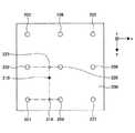
また、測定点201〜209からずれた位置が操作された場合は、その周辺の測定点における変位量の閾値を用いて、荷重が基準値に達しているかを判断することができる。図7及び図8は、荷重の判断方法の一例を示す図である。図7に示すように、ここでは、測定点201、202、204及び205がなす四角形の内側の点210が操作されたとする。この場合、図8(a)に示すように、X軸方向に並ぶ2つの測定点202及び測定点205の間で、点210とY座標が同一の点225における変位量の閾値を、測定点202及び測定点205における各閾値から線形補間により算出する。同様に、図8(b)に示すように、X軸方向に並ぶ2つの測定点201及び測定点204の間で、点210とY座標が同一の点214における変位量の閾値を、測定点201及び測定点204における各閾値から線形補間により算出する。そして、図8(c)に示すように、点225及び点214の各閾値から点210における閾値を線形補間により算出する。その一方で、点210におけるZ軸方向の変位量は、上記の式(3)から算出することができる。従って、これらを比較することで、測定点201〜209からずれた位置の点210に加えられた荷重が基準値に達しているか否かを判断することができる。 Further, when the position deviated from the measurement points 201 to 209 is operated, it is possible to determine whether the load has reached the reference value by using the threshold value of the displacement amount at the measurement points around the measurement points. 7 and 8 are diagrams showing an example of a load determination method. As shown in FIG. 7, here, it is assumed that the
信号処理装置180は、上記のような基本原理に基づいて、タッチパッド140の操作位置に加えられた荷重が触覚フィードバックを生じさせる基準値に達しているか判断し、その結果に応じてアクチュエータ160を駆動して触覚フィードバックを生じさせる。図9は、信号処理装置180の構成を示す図である。 Based on the above basic principle, the
信号処理装置180は、CPU(Central Processing Unit)181、ROM(Read Only Memory)182、RAM(Random Access Memory)183及び補助記憶部184を備える。CPU181、ROM182、RAM183及び補助記憶部184は、いわゆるコンピュータを構成する。信号処理装置180の各部は、バス185を介して相互に接続されている。 The
CPU181は、補助記憶部184に格納された各種プログラム(例えば、荷重判定プログラム)を実行する。 The
ROM182は不揮発性の主記憶デバイスである。ROM182は、補助記憶部184に格納された各種プログラムを、CPU181が実行するために必要な各種プログラム、データ等を格納する。具体的には、ROM182は、BIOS(Basic Input/Output System)やEFI(Extensible Firmware Interface)等のブートプログラムなどを格納する。 The
RAM183は、DRAM(Dynamic Random Access Memory)やSRAM(Static Random Access Memory)等の揮発性の主記憶デバイスである。RAM183は、補助記憶部184に格納された各種プログラムがCPU181によって実行される際に展開される作業領域として機能する。 The
補助記憶部184は、CPU181により実行される各種プログラム及び各種プログラムがCPU181によって実行されることで生成される各種データを格納する補助記憶デバイスである。 The
信号処理装置180は、このようなハードウェア構成を備えており、次のような処理を行う。図10は、信号処理装置180による処理の内容を示すフローチャートである。 The
先ず、信号処理装置180はタッチパッド140を検出する(ステップS1)。そして、タッチパッド140に指が接触したか否かを判断し(ステップS2)、指が接触していない場合には、フォトインタラプタ171〜174のドリフトをキャンセルする(ステップS3)。 First, the
一方、タッチパッド140に指が接触したと判断した場合は、フォトインタラプタ171〜174の各々から検出信号を取得する(ステップS4)。例えば、フォトインタラプタ171〜174の出力信号がアナログ信号である場合、デジタル信号への変換後の信号を取得する。 On the other hand, when it is determined that the finger touches the
次いで、フォトインタラプタ171〜174の各検出信号から、平板部131のこれらによる検出位置でのZ軸方向の変位量Z1〜Z4を計算する(ステップS5)。Next, from each of the detection signals of the photo-
その後、4つのフォトインタラプタ171〜174のうちの3つが構成する複数の三角形のうちから、1つの三角形を代表三角形として決定する(ステップS6)。例えば、代表三角形としては、タッチパッド140の操作位置を内側に含む三角形を用いることが好ましい。すなわち、図5において点eが触れられている場合であれば、三角形acd又は三角形acbを用いることが好ましい。操作位置とフォトインタラプタ171〜174との間の距離が小さいほど高い精度が得られるためである。 Then, one triangle is determined as the representative triangle from the plurality of triangles composed of three of the four
続いて、タッチパッド140の操作位置におけるZ軸方向の変位量Zを算出する(ステップS7)。すなわち、式(3)を用いて、ステップS6で決定した代表三角形をなす3つのフォトインタラプタの検出信号から計算したZ軸方向の変位量、並びにタッチパッド140により検出された操作位置のX座標及びY座標から、操作位置でのZ軸方向の変位量Zを算出する。 Subsequently, the displacement amount Z in the Z-axis direction at the operation position of the
また、図6に示す例のような、加えられた荷重とZ軸方向の変位量との関係を予め求め、これをROM182に記憶させておき、これを読み出して、操作位置でのZ軸方向の閾値(オン閾値)Zthを算出する(ステップS8)。 Further, as in the example shown in FIG. 6, the relationship between the applied load and the displacement amount in the Z-axis direction is obtained in advance, stored in the
そして、変位量Zがオン閾値Zth超であるか判断し(ステップS9)、オン閾値Zth超であれば、加えられた荷重が基準値超であるとして、アクチュエータ160を駆動して触覚フィードバックを実施する(ステップS10)。 Then, it is determined whether the displacement amount Z exceeds the on-threshold value Zth (step S9), and if it exceeds the on-threshold value Zth, it is assumed that the applied load exceeds the reference value, and the
本実施形態に係る入力装置100は、このようにして、触覚フィードバックを実施する。フォトインタラプタ171〜174は平板部131の点171A〜174AのZ座標を高精度で検出でき、また、タッチパッド140は操作位置のX座標及びY座標を高精度で検出することができる。従って、上記の処理によれば、操作位置のZ座標も高精度で検出することができる。従って、例えばオン閾値Zthを数十μm程度と小さな値としても、高精度で触覚フィードバックのオン/オフの判断を行うことができる。 The
なお、アクチュエータ160の周辺に設けられるラバー193は、可動ベース130の縁の近傍に設けられるラバー191及びラバー192よりも硬いことが好ましい。ラバー191及びラバー192は、固定ベース110とベゼル120との間で可動ベース130を、アクチュエータ160の駆動により振動可能な程度に支持する。ラバー191及びラバー192の硬さが高すぎると、アクチュエータ160が駆動してもユーザに振動を伝えにくい。一方、操作に応じて可動ベース130が傾斜しやすいほどフォトインタラプタ171〜174によるZ軸方向の変位量Z1〜Z4が大きくなりやすく、誤差が小さくなりやすい。また、ラバー303が硬いほど、ユーザへの反発力が大きくなる。従って、ラバー193はラバー191及びラバー192より硬いことが好ましい。The
図11は、可動ベースの傾斜を示す模式図である。図11に示すように、可動ベース130及びタッチパッド140を含む操作パネル部材302の縁部に、ラバー191及びラバー192に相当するラバー303が配置され、中心部にラバー193に相当するラバー304が配置されているとする。この場合、操作パネル部材302の縁部近傍が指301で押圧されると、その近傍のラバー303が大きく圧縮される一方で、ラバー304はほとんど圧縮されない。また、他方のラバー303については、操作パネル部材302がラバー303から上方に持ち上がる。従って、両ラバー303の近傍において操作パネル部材302の変位量が大きなものとなる。一方、ラバー304の硬さがラバー303の硬さと同程度であれば、すべてのラバー303及びラバー304が圧縮され、その差は小さなものとなる。従って、両ラバー303の近傍における操作パネル部材302の変位量は比較的小さなものとなる。なお、入力装置100においては、アクチュエータ160も図11中のラバー304の一部として傾斜の支点として機能し得る。 FIG. 11 is a schematic view showing the inclination of the movable base. As shown in FIG. 11,
また、上記の処理では、1つの代表三角形を特定し、操作位置での変位量を算出し、この変位量に基づく判断を行っているが、2つ以上の代表三角形を特定し、各代表三角形について変位量(第1変位量、第2変位量、等)を算出し、これら変位量の平均値を求め、この平均値に基づく判断を行ってもよい。このような処理によれば、より精度の高い判断を行うことができる。 Further, in the above processing, one representative triangle is specified, the displacement amount at the operating position is calculated, and the judgment is made based on this displacement amount. However, two or more representative triangles are specified and each representative triangle is specified. The displacement amount (first displacement amount, second displacement amount, etc.) may be calculated, the average value of these displacement amounts may be obtained, and a judgment may be made based on this average value. According to such a process, a more accurate judgment can be made.
また、フォトインタラプタ171〜174は平板部131に接触しないため、操作に伴うタッチパッド140の移動に影響を及ぼさない。フォトインタラプタ171〜174に代えて静電センサ等の非接触の位置検出センサを用いてもよい。 Further, since the
本開示の入力装置は、特に自動車のセンターコンソールに設けられる入力装置に好適である。センターコンソールは運転席及び助手席の間に設けられるため、センターコンソールに設けられる入力装置の平面形状は複雑なものになることがある。本開示の入力装置においては、3つのセンサを配置する位置は任意であるため、操作パネル部材の平面形状が複雑なものであっても、適切に操作パネル部材の変位量を高精度で検出することができる。 The input device of the present disclosure is particularly suitable for an input device provided in a center console of an automobile. Since the center console is provided between the driver's seat and the passenger seat, the planar shape of the input device provided in the center console may be complicated. In the input device of the present disclosure, since the positions where the three sensors are arranged are arbitrary, the displacement amount of the operation panel member can be appropriately detected with high accuracy even if the planar shape of the operation panel member is complicated. be able to.
以上、好ましい実施形態等について詳説したが、上述した実施形態等に制限されることはなく、請求の範囲に記載された範囲を逸脱することなく、上述した実施形態等に種々の変形及び置換を加えることができる。 Although the preferred embodiments and the like have been described in detail above, the above-described embodiments and the like are not limited to the above-described embodiments, and various modifications and substitutions are made to the above-mentioned embodiments and the like without departing from the scope of the claims. Can be added.
本国際出願は、2018年5月18日に出願した日本国特許出願第2018−096488号に基づく優先権を主張するものであり、当該出願の全内容を本国際出願に援用する。 This international application claims priority based on Japanese Patent Application No. 2018-0964888 filed on May 18, 2018, and the entire contents of the application are incorporated into this international application.
100 入力装置
110 固定ベース
120 ベゼル
130 可動ベース
140 タッチパッド
150 化粧パネル
160 アクチュエータ
171〜174 フォトインタラプタ
180 信号処理装置
191〜193 ラバー100
Claims (10)
Translated fromJapanese前記操作パネル部材から離間した基準面内に配置され、それぞれが前記操作パネル部材との間の距離を検出する第1のセンサ、第2のセンサ及び第3のセンサと、
前記操作パネル部材及び前記第1のセンサ、前記第2のセンサ及び前記第3のセンサからの信号を処理する信号処理装置と、
を有し、
前記操作パネル部材は、前記操作位置に加えられた荷重に応じて前記基準面に対して傾斜可能であり、
前記信号処理装置は、前記操作パネル部材が検出した前記入力操作面内の前記操作位置の座標並びに前記第1のセンサ、前記第2のセンサ及び前記第3のセンサが検出したそれぞれの距離から前記操作位置における前記操作パネル部材の操作前後での変位量を算出することを特徴とする入力装置。An operation panel member that has an input operation surface and detects the coordinates of the operation position in the input operation surface.
A first sensor, a second sensor, and a third sensor arranged in a reference plane separated from the operation panel member and each detecting a distance between the operation panel member and the operation panel member.
A signal processing device that processes signals from the operation panel member, the first sensor, the second sensor, and the third sensor.
Have,
The operation panel member can be tilted with respect to the reference plane according to the load applied to the operation position.
The signal processing device is said to be described from the coordinates of the operation position in the input operation surface detected by the operation panel member and the respective distances detected by the first sensor, the second sensor and the third sensor. An input device for calculating the amount of displacement of the operation panel member at an operation position before and after operation.
前記第2のセンサは前記操作パネル部材の第2の点との間の距離を検出し、
前記第3のセンサは前記操作パネル部材の第3の点との間の距離を検出し、
前記信号処理装置は、前記第1の点、前記第2の点及び前記第3の点を含む平面を特定し、前記操作パネル部材が検出した前記入力操作面内の前記操作位置の座標に対応する前記平面内の座標を特定することを特徴とする請求項1に記載の入力装置。The first sensor detects the distance between the operation panel member and the first point.
The second sensor detects the distance between the operation panel member and the second point.
The third sensor detects the distance between the operation panel member and the third point.
The signal processing device identifies a plane including the first point, the second point, and the third point, and corresponds to the coordinates of the operation position in the input operation surface detected by the operation panel member. The input device according to claim 1, wherein the coordinates in the plane are specified.
タッチパッド部と、
前記タッチパッド部を保持する保持部と、
を有し、
前記第1のセンサ、前記第2のセンサ及び前記第3のセンサは前記保持部との間の距離を検出することを特徴とする請求項1乃至3のいずれか1項に記載の入力装置。The operation panel member
With the touch pad
A holding portion that holds the touch pad portion and
Have,
The input device according to any one of claims 1 to 3, wherein the first sensor, the second sensor, and the third sensor detect a distance from the holding portion.
前記支持部材に、前記操作パネル部材を振動可能に支持する第1の弾性部材を有することを特徴とする請求項6又は7に記載の入力装置。A support member having the reference surface and
The input device according to claim 6 or 7, wherein the support member includes a first elastic member that oscillateably supports the operation panel member.
前記信号処理装置は、
前記変位量を第1変位量として算出するとともに、
前記操作パネル部材が検出した前記操作位置の座標並びに前記第1のセンサ、前記第2のセンサ及び前記第3のセンサのうちの2つと前記第4のセンサとが検出したそれぞれの距離から前記操作位置における前記操作パネル部材の操作前後での変位量を第2変位量として算出し、
前記第1変位量と前記第2変位量との平均値を算出することを特徴とする請求項1乃至9のいずれか1項に記載の入力装置。It has a fourth sensor that is arranged in the reference plane at a distance from the first sensor, the second sensor, and the third sensor, and detects a distance between the operation panel member and the sensor.
The signal processing device is
While calculating the displacement amount as the first displacement amount,
The operation is performed from the coordinates of the operation position detected by the operation panel member and the distances detected by the first sensor, the second sensor, the third sensor, and the fourth sensor. The amount of displacement before and after the operation of the operation panel member at the position is calculated as the amount of second displacement.
The input device according to any one of claims 1 to 9, wherein an average value of the first displacement amount and the second displacement amount is calculated.
Applications Claiming Priority (3)
| Application Number | Priority Date | Filing Date | Title |
|---|---|---|---|
| JP2018096488 | 2018-05-18 | ||
| JP2018096488 | 2018-05-18 | ||
| PCT/JP2019/008916WO2019220749A1 (en) | 2018-05-18 | 2019-03-06 | Input device |
Publications (2)
| Publication Number | Publication Date |
|---|---|
| JPWO2019220749A1 JPWO2019220749A1 (en) | 2021-05-13 |
| JP6940698B2true JP6940698B2 (en) | 2021-09-29 |
Family
ID=68540205
Family Applications (1)
| Application Number | Title | Priority Date | Filing Date |
|---|---|---|---|
| JP2020519477AActiveJP6940698B2 (en) | 2018-05-18 | 2019-03-06 | Input device |
Country Status (5)
| Country | Link |
|---|---|
| US (1) | US20210055810A1 (en) |
| EP (1) | EP3796138A4 (en) |
| JP (1) | JP6940698B2 (en) |
| CN (1) | CN112005202A (en) |
| WO (1) | WO2019220749A1 (en) |
Families Citing this family (2)
| Publication number | Priority date | Publication date | Assignee | Title |
|---|---|---|---|---|
| JP7581590B2 (en)* | 2020-10-30 | 2024-11-13 | ミネベアミツミ株式会社 | Tactile feedback device |
| CN117203605A (en)* | 2021-06-29 | 2023-12-08 | 阿尔卑斯阿尔派株式会社 | Input device |
Family Cites Families (52)
| Publication number | Priority date | Publication date | Assignee | Title |
|---|---|---|---|---|
| JPS62147521A (en)* | 1985-12-23 | 1987-07-01 | Nippon Telegr & Teleph Corp <Ntt> | Coordinates input device |
| BE1007462A3 (en)* | 1993-08-26 | 1995-07-04 | Philips Electronics Nv | Data processing device with touch sensor and power. |
| US5680160A (en)* | 1995-02-09 | 1997-10-21 | Leading Edge Industries, Inc. | Touch activated electroluminescent lamp and display switch |
| DE19526653A1 (en)* | 1995-07-21 | 1997-01-23 | Carmen Diessner | Force measuring device |
| US5854625A (en)* | 1996-11-06 | 1998-12-29 | Synaptics, Incorporated | Force sensing touchpad |
| US6429846B2 (en)* | 1998-06-23 | 2002-08-06 | Immersion Corporation | Haptic feedback for touchpads and other touch controls |
| US6822635B2 (en)* | 2000-01-19 | 2004-11-23 | Immersion Corporation | Haptic interface for laptop computers and other portable devices |
| US6555235B1 (en)* | 2000-07-06 | 2003-04-29 | 3M Innovative Properties Co. | Touch screen system |
| US7183948B2 (en)* | 2001-04-13 | 2007-02-27 | 3M Innovative Properties Company | Tangential force control in a touch location device |
| US20020149571A1 (en)* | 2001-04-13 | 2002-10-17 | Roberts Jerry B. | Method and apparatus for force-based touch input |
| CA2353697A1 (en)* | 2001-07-24 | 2003-01-24 | Tactex Controls Inc. | Touch sensitive membrane |
| US7158122B2 (en)* | 2002-05-17 | 2007-01-02 | 3M Innovative Properties Company | Calibration of force based touch panel systems |
| US8488308B2 (en)* | 2003-02-12 | 2013-07-16 | 3M Innovative Properties Company | Sealed force-based touch sensor |
| JP4198527B2 (en)* | 2003-05-26 | 2008-12-17 | 富士通コンポーネント株式会社 | Touch panel and display device |
| US20060181517A1 (en)* | 2005-02-11 | 2006-08-17 | Apple Computer, Inc. | Display actuator |
| JP4359757B2 (en)* | 2003-09-17 | 2009-11-04 | ソニー株式会社 | Information display device |
| JP4545424B2 (en)* | 2003-12-11 | 2010-09-15 | アルプス電気株式会社 | Coordinate input device and image display device and electronic apparatus provided with the same |
| US7411584B2 (en)* | 2003-12-31 | 2008-08-12 | 3M Innovative Properties Company | Touch sensitive device employing bending wave vibration sensing and excitation transducers |
| US7315300B2 (en)* | 2003-12-31 | 2008-01-01 | 3M Innovative Properties Company | Touch sensitive device employing impulse reconstruction |
| US9019209B2 (en)* | 2005-06-08 | 2015-04-28 | 3M Innovative Properties Company | Touch location determination involving multiple touch location processes |
| US20090174679A1 (en)* | 2008-01-04 | 2009-07-09 | Wayne Carl Westerman | Selective Rejection of Touch Contacts in an Edge Region of a Touch Surface |
| WO2010024008A1 (en)* | 2008-08-29 | 2010-03-04 | シャープ株式会社 | Coordinate sensor, electronic device, display device, and light-receiving unit |
| US8294047B2 (en)* | 2008-12-08 | 2012-10-23 | Apple Inc. | Selective input signal rejection and modification |
| TWI412968B (en)* | 2008-12-25 | 2013-10-21 | Nissha Printing | Touch panel having press detection function and pressure sensitive sensor for the touch panel |
| US9024907B2 (en)* | 2009-04-03 | 2015-05-05 | Synaptics Incorporated | Input device with capacitive force sensor and method for constructing the same |
| US10068728B2 (en)* | 2009-10-15 | 2018-09-04 | Synaptics Incorporated | Touchpad with capacitive force sensing |
| US8633916B2 (en) | 2009-12-10 | 2014-01-21 | Apple, Inc. | Touch pad with force sensors and actuator feedback |
| JP5006377B2 (en)* | 2009-12-25 | 2012-08-22 | 雅信 鯨田 | 3D pointing device |
| TWI544458B (en)* | 2010-04-02 | 2016-08-01 | 元太科技工業股份有限公司 | Display panel |
| US20110248948A1 (en)* | 2010-04-08 | 2011-10-13 | Research In Motion Limited | Touch-sensitive device and method of control |
| US8552997B2 (en)* | 2010-04-23 | 2013-10-08 | Blackberry Limited | Portable electronic device including tactile touch-sensitive input device |
| US8610681B2 (en)* | 2010-06-03 | 2013-12-17 | Sony Corporation | Information processing apparatus and information processing method |
| FR2966613B1 (en)* | 2010-10-20 | 2012-12-28 | Dav | TOUCH INTERFACE MODULE WITH HAPTIC RETURN |
| JP2012103797A (en)* | 2010-11-08 | 2012-05-31 | Sony Corp | Input device, coordinate detection method and program |
| US20130063383A1 (en)* | 2011-02-28 | 2013-03-14 | Research In Motion Limited | Electronic device and method of displaying information in response to detecting a gesture |
| WO2012153536A1 (en)* | 2011-05-12 | 2012-11-15 | パナソニック株式会社 | Coordinates input device and coordinates input method |
| JP2013161357A (en)* | 2012-02-07 | 2013-08-19 | Tokai Rika Co Ltd | Input device |
| US9857919B2 (en)* | 2012-05-17 | 2018-01-02 | Hong Kong Applied Science And Technology Research | Wearable device with intelligent user-input interface |
| JP5355751B1 (en)* | 2012-06-12 | 2013-11-27 | 株式会社東芝 | Electronic device and control method of electronic device |
| JP5898779B2 (en)* | 2012-10-11 | 2016-04-06 | アルプス電気株式会社 | INPUT DEVICE AND METHOD FOR DETECTING MULTI-POINT LOAD USING THE INPUT DEVICE |
| FR2999742B1 (en)* | 2012-12-13 | 2018-03-30 | Dav | TOUCH CONTROL INTERFACE |
| CN103064537A (en)* | 2012-12-14 | 2013-04-24 | 苏州瀚瑞微电子有限公司 | Pressure detecting capacitance pen |
| KR20140081313A (en)* | 2012-12-21 | 2014-07-01 | 삼성전기주식회사 | Touch sensor |
| EP3177978A4 (en)* | 2014-08-04 | 2018-03-21 | Nextinput, Inc. | Force sensitive touch panel devices |
| CN107850961B (en)* | 2015-07-16 | 2021-02-26 | 阿尔卑斯阿尔派株式会社 | Operation feeling imparting input device |
| EP3326725B1 (en)* | 2015-07-24 | 2020-07-08 | Alps Alpine Co., Ltd. | Vibration-generating device and operation feel-imparting input device using said vibration-generating device |
| US20170045976A1 (en)* | 2015-08-10 | 2017-02-16 | Apple Inc. | Electronic Devices With Shear Force Sensing |
| CN108139819B (en)* | 2015-10-28 | 2021-06-01 | 阿尔卑斯阿尔派株式会社 | operating device |
| KR101680004B1 (en)* | 2016-01-29 | 2016-11-25 | 현대자동차주식회사 | Touch input apparatus |
| JP6846187B2 (en) | 2016-12-15 | 2021-03-24 | 株式会社テイエルブイ | Valve device |
| JP6876141B2 (en)* | 2017-10-13 | 2021-05-26 | アルプスアルパイン株式会社 | Input device |
| CN112534380B (en)* | 2018-08-29 | 2024-05-17 | 阿尔卑斯阿尔派株式会社 | Input device, control method and storage medium |
- 2019
- 2019-03-06JPJP2020519477Apatent/JP6940698B2/enactiveActive
- 2019-03-06CNCN201980025647.0Apatent/CN112005202A/ennot_activeWithdrawn
- 2019-03-06EPEP19803096.7Apatent/EP3796138A4/ennot_activeWithdrawn
- 2019-03-06WOPCT/JP2019/008916patent/WO2019220749A1/ennot_activeCeased
- 2020
- 2020-11-10USUS17/093,976patent/US20210055810A1/ennot_activeAbandoned
Also Published As
| Publication number | Publication date |
|---|---|
| WO2019220749A1 (en) | 2019-11-21 |
| EP3796138A1 (en) | 2021-03-24 |
| JPWO2019220749A1 (en) | 2021-05-13 |
| EP3796138A4 (en) | 2022-03-09 |
| US20210055810A1 (en) | 2021-02-25 |
| CN112005202A (en) | 2020-11-27 |
Similar Documents
| Publication | Publication Date | Title |
|---|---|---|
| US20180046307A1 (en) | Multi-Force Input Device | |
| JPWO2019116490A1 (en) | Operation support device, touch panel device, and touch panel input system | |
| US11435832B2 (en) | Input device, control method, and non-transitory recording medium | |
| CN101739170A (en) | Touch panel component and touch panel system | |
| JP6940698B2 (en) | Input device | |
| US11379052B2 (en) | Input device | |
| TW202111501A (en) | Touch panel device, touch operation determination method, and touch operation determination program | |
| US10649555B2 (en) | Input interface device, control method and non-transitory computer-readable medium | |
| JP2018005781A (en) | Manipulation device | |
| JP4391895B2 (en) | Pressure detection device | |
| JP7094631B2 (en) | Input device | |
| JP6725775B1 (en) | Touch panel device | |
| WO2023276300A1 (en) | Input device | |
| KR101598807B1 (en) | Method and digitizer for measuring slope of a pen | |
| JP2019016051A (en) | Operation input device | |
| US20250085818A1 (en) | Input Device | |
| JP2018190278A (en) | Operation input device | |
| JP6731196B2 (en) | Operating device | |
| US20150234424A1 (en) | Operation system | |
| WO2017061394A1 (en) | Tactile sense presentation device | |
| JP2018092315A (en) | Operation input device | |
| JP2024080074A (en) | Tactile sensation presentation device and tactile sensation presentation method | |
| JP2001051789A (en) | pointing device | |
| JPWO2019009138A1 (en) | Operation input device | |
| JP2018092316A (en) | Operation input device |
Legal Events
| Date | Code | Title | Description |
|---|---|---|---|
| A621 | Written request for application examination | Free format text:JAPANESE INTERMEDIATE CODE: A621 Effective date:20201110 | |
| TRDD | Decision of grant or rejection written | ||
| A01 | Written decision to grant a patent or to grant a registration (utility model) | Free format text:JAPANESE INTERMEDIATE CODE: A01 Effective date:20210810 | |
| A61 | First payment of annual fees (during grant procedure) | Free format text:JAPANESE INTERMEDIATE CODE: A61 Effective date:20210902 | |
| R150 | Certificate of patent or registration of utility model | Ref document number:6940698 Country of ref document:JP Free format text:JAPANESE INTERMEDIATE CODE: R150 |