JP6940537B2 - Equipment and methods for sealing tissues with low power - Google Patents
Equipment and methods for sealing tissues with low powerDownload PDFInfo
- Publication number
- JP6940537B2 JP6940537B2JP2019024359AJP2019024359AJP6940537B2JP 6940537 B2JP6940537 B2JP 6940537B2JP 2019024359 AJP2019024359 AJP 2019024359AJP 2019024359 AJP2019024359 AJP 2019024359AJP 6940537 B2JP6940537 B2JP 6940537B2
- Authority
- JP
- Japan
- Prior art keywords
- power
- jaws
- sealing
- pair
- tissue
- Prior art date
- Legal status (The legal status is an assumption and is not a legal conclusion. Google has not performed a legal analysis and makes no representation as to the accuracy of the status listed.)
- Active
Links
Images


Classifications
- A—HUMAN NECESSITIES
- A61—MEDICAL OR VETERINARY SCIENCE; HYGIENE
- A61B—DIAGNOSIS; SURGERY; IDENTIFICATION
- A61B18/00—Surgical instruments, devices or methods for transferring non-mechanical forms of energy to or from the body
- A61B18/04—Surgical instruments, devices or methods for transferring non-mechanical forms of energy to or from the body by heating
- A61B18/12—Surgical instruments, devices or methods for transferring non-mechanical forms of energy to or from the body by heating by passing a current through the tissue to be heated, e.g. high-frequency current
- A61B18/1206—Generators therefor
- A61B18/1233—Generators therefor with circuits for assuring patient safety
- A—HUMAN NECESSITIES
- A61—MEDICAL OR VETERINARY SCIENCE; HYGIENE
- A61B—DIAGNOSIS; SURGERY; IDENTIFICATION
- A61B18/00—Surgical instruments, devices or methods for transferring non-mechanical forms of energy to or from the body
- A61B18/04—Surgical instruments, devices or methods for transferring non-mechanical forms of energy to or from the body by heating
- A61B18/12—Surgical instruments, devices or methods for transferring non-mechanical forms of energy to or from the body by heating by passing a current through the tissue to be heated, e.g. high-frequency current
- A61B18/14—Probes or electrodes therefor
- A61B18/1442—Probes having pivoting end effectors, e.g. forceps
- A61B18/1445—Probes having pivoting end effectors, e.g. forceps at the distal end of a shaft, e.g. forceps or scissors at the end of a rigid rod
- A—HUMAN NECESSITIES
- A61—MEDICAL OR VETERINARY SCIENCE; HYGIENE
- A61B—DIAGNOSIS; SURGERY; IDENTIFICATION
- A61B18/00—Surgical instruments, devices or methods for transferring non-mechanical forms of energy to or from the body
- A61B18/04—Surgical instruments, devices or methods for transferring non-mechanical forms of energy to or from the body by heating
- A61B18/12—Surgical instruments, devices or methods for transferring non-mechanical forms of energy to or from the body by heating by passing a current through the tissue to be heated, e.g. high-frequency current
- A61B18/1206—Generators therefor
- A—HUMAN NECESSITIES
- A61—MEDICAL OR VETERINARY SCIENCE; HYGIENE
- A61B—DIAGNOSIS; SURGERY; IDENTIFICATION
- A61B18/00—Surgical instruments, devices or methods for transferring non-mechanical forms of energy to or from the body
- A61B18/04—Surgical instruments, devices or methods for transferring non-mechanical forms of energy to or from the body by heating
- A61B18/12—Surgical instruments, devices or methods for transferring non-mechanical forms of energy to or from the body by heating by passing a current through the tissue to be heated, e.g. high-frequency current
- A61B18/14—Probes or electrodes therefor
- A61B18/1482—Probes or electrodes therefor having a long rigid shaft for accessing the inner body transcutaneously in minimal invasive surgery, e.g. laparoscopy
- A—HUMAN NECESSITIES
- A61—MEDICAL OR VETERINARY SCIENCE; HYGIENE
- A61B—DIAGNOSIS; SURGERY; IDENTIFICATION
- A61B17/00—Surgical instruments, devices or methods
- A61B2017/00017—Electrical control of surgical instruments
- A61B2017/00137—Details of operation mode
- A61B2017/00141—Details of operation mode continuous, e.g. wave
- A—HUMAN NECESSITIES
- A61—MEDICAL OR VETERINARY SCIENCE; HYGIENE
- A61B—DIAGNOSIS; SURGERY; IDENTIFICATION
- A61B18/00—Surgical instruments, devices or methods for transferring non-mechanical forms of energy to or from the body
- A61B2018/00571—Surgical instruments, devices or methods for transferring non-mechanical forms of energy to or from the body for achieving a particular surgical effect
- A61B2018/00607—Coagulation and cutting with the same instrument
- A—HUMAN NECESSITIES
- A61—MEDICAL OR VETERINARY SCIENCE; HYGIENE
- A61B—DIAGNOSIS; SURGERY; IDENTIFICATION
- A61B18/00—Surgical instruments, devices or methods for transferring non-mechanical forms of energy to or from the body
- A61B2018/00571—Surgical instruments, devices or methods for transferring non-mechanical forms of energy to or from the body for achieving a particular surgical effect
- A61B2018/00619—Welding
- A—HUMAN NECESSITIES
- A61—MEDICAL OR VETERINARY SCIENCE; HYGIENE
- A61B—DIAGNOSIS; SURGERY; IDENTIFICATION
- A61B18/00—Surgical instruments, devices or methods for transferring non-mechanical forms of energy to or from the body
- A61B2018/00571—Surgical instruments, devices or methods for transferring non-mechanical forms of energy to or from the body for achieving a particular surgical effect
- A61B2018/0063—Sealing
- A—HUMAN NECESSITIES
- A61—MEDICAL OR VETERINARY SCIENCE; HYGIENE
- A61B—DIAGNOSIS; SURGERY; IDENTIFICATION
- A61B18/00—Surgical instruments, devices or methods for transferring non-mechanical forms of energy to or from the body
- A61B2018/00636—Sensing and controlling the application of energy
- A61B2018/00642—Sensing and controlling the application of energy with feedback, i.e. closed loop control
- A—HUMAN NECESSITIES
- A61—MEDICAL OR VETERINARY SCIENCE; HYGIENE
- A61B—DIAGNOSIS; SURGERY; IDENTIFICATION
- A61B18/00—Surgical instruments, devices or methods for transferring non-mechanical forms of energy to or from the body
- A61B2018/00636—Sensing and controlling the application of energy
- A61B2018/00666—Sensing and controlling the application of energy using a threshold value
- A61B2018/00678—Sensing and controlling the application of energy using a threshold value upper
- A—HUMAN NECESSITIES
- A61—MEDICAL OR VETERINARY SCIENCE; HYGIENE
- A61B—DIAGNOSIS; SURGERY; IDENTIFICATION
- A61B18/00—Surgical instruments, devices or methods for transferring non-mechanical forms of energy to or from the body
- A61B2018/00636—Sensing and controlling the application of energy
- A61B2018/00696—Controlled or regulated parameters
- A61B2018/00702—Power or energy
- A61B2018/00708—Power or energy switching the power on or off
- A—HUMAN NECESSITIES
- A61—MEDICAL OR VETERINARY SCIENCE; HYGIENE
- A61B—DIAGNOSIS; SURGERY; IDENTIFICATION
- A61B18/00—Surgical instruments, devices or methods for transferring non-mechanical forms of energy to or from the body
- A61B2018/00636—Sensing and controlling the application of energy
- A61B2018/00696—Controlled or regulated parameters
- A61B2018/0072—Current
- A—HUMAN NECESSITIES
- A61—MEDICAL OR VETERINARY SCIENCE; HYGIENE
- A61B—DIAGNOSIS; SURGERY; IDENTIFICATION
- A61B18/00—Surgical instruments, devices or methods for transferring non-mechanical forms of energy to or from the body
- A61B2018/00636—Sensing and controlling the application of energy
- A61B2018/00696—Controlled or regulated parameters
- A61B2018/00767—Voltage
- A—HUMAN NECESSITIES
- A61—MEDICAL OR VETERINARY SCIENCE; HYGIENE
- A61B—DIAGNOSIS; SURGERY; IDENTIFICATION
- A61B18/00—Surgical instruments, devices or methods for transferring non-mechanical forms of energy to or from the body
- A61B2018/00636—Sensing and controlling the application of energy
- A61B2018/00773—Sensed parameters
- A61B2018/00875—Resistance or impedance
Landscapes
- Health & Medical Sciences (AREA)
- Surgery (AREA)
- Engineering & Computer Science (AREA)
- Life Sciences & Earth Sciences (AREA)
- Biomedical Technology (AREA)
- Otolaryngology (AREA)
- Nuclear Medicine, Radiotherapy & Molecular Imaging (AREA)
- Plasma & Fusion (AREA)
- Physics & Mathematics (AREA)
- Heart & Thoracic Surgery (AREA)
- Medical Informatics (AREA)
- Molecular Biology (AREA)
- Animal Behavior & Ethology (AREA)
- General Health & Medical Sciences (AREA)
- Public Health (AREA)
- Veterinary Medicine (AREA)
- Surgical Instruments (AREA)
Description
Translated fromJapanese 優先権及び関連出願
本出願は、2010年6月7日付けで出願された米国仮特許出願第61/352,114号、及び2010年6月6日付けで出願された米国特許出願第13/153,513号の優先権を主張する。出願第61/352,114号及び出願第13/153,513号の詳細は、参照することにより本出願全体に、そしてあらゆる適切な目的のために組み入れられる。Priority and related applications This application is a US provisional patent application No. 61 / 352,114 filed on June 7, 2010, and a US patent application No. 13 / 153,513 filed on June 6, 2010. Claim the priority of. Details of Application No. 61 / 352,114 and Application No. 13 / 153,513 are incorporated by reference throughout the application and for any suitable purpose.
本発明の態様は、外科処置中に血管をシーリングするために無線周波数エネルギーを利用する電気外科的な処置、技術、及び装置に関する。具体的に、また一例として挙げるならば、本発明の態様は、正確に配置された血管、或いはマイクロ外科処置又はアクセス困難な解剖又は小児科患者の一般外科処置においてしばしば見いだされる傷つきやすい又はアクセス困難な血管にシーリングを施すための装置及び技術に関する。 Aspects of the invention relate to electrosurgical procedures, techniques, and devices that utilize radio frequency energy to seal blood vessels during a surgical procedure. Specifically, and by way of example, aspects of the invention are vulnerable or inaccessible, often found in precisely placed blood vessels, or in microsurgical procedures or inaccessible anatomy or general surgical procedures in pediatric patients. It relates to a device and a technique for sealing a blood vessel.
脈管をシーリングする外科処置に際して電気外科的エネルギーを使用することは一般的であり、この電気外科的エネルギーは多年にわたり種々様々な外科技術と相俟って利用されている。一般に、脈管シーリングにおいて使用される電気外科用装置は、組織、例えば血管を切開、凝固、乾燥、又はシーリングする手段として、生体組織に印加される圧力と高周波電気エネルギーとの組み合わせに頼っている。脈管シーリングの場合、電気外科的エネルギーは、コラーゲン溶融及び組織融合を生じさせるために役立つ。今日市販され従来技術において記載されたほとんどのRF外科用装置は電力供給システムと、エンドエフェクタとを有している。エンドエフェクタは、広範囲の状況、組織厚、組織体積、及びエンドエフェクタのバイドサイズに対応するようにサイズ設定されている。具体的には、血管シーリング技術は、種々の外科的状況においてシールを形成するために、比較的高い電流設定値、大きいエンドエフェクタ・サイズを用いることに常に頼っている。2アンペア未満の電流で動作する信頼性高い脈管シーリング器具を製造することは誰にもできていない。 It is common to use electrosurgical energy in surgical procedures to seal vessels, and this electrosurgical energy has been used in combination with various surgical techniques for many years. Generally, electrosurgical devices used in vascular sealing rely on a combination of pressure applied to living tissue and high frequency electrical energy as a means of incising, coagulating, drying, or sealing tissue, such as blood vessels. .. In the case of vascular sealing, electrosurgical energy helps to cause collagen melting and tissue fusion. Most RF surgical devices commercially available today and described in the prior art have a power supply system and an end effector. The end effector is sized to accommodate a wide range of conditions, tissue thickness, tissue volume, and end effector bid size. Specifically, vascular sealing techniques have always relied on the use of relatively high current settings, large end effector sizes to form seals in a variety of surgical situations. No one has been able to manufacture a reliable vascular sealing device that operates at currents below 2 amps.
周知の装置で凝固又は血管シーリングを施すために、エンドエフェクタによって供給される平均電力密度は典型的には切開閾値未満に低減される。いくつかの事例(例えば単極凝固器具)では変調正弦波を使用し、これに伴う全効果は、組織を切開点まで焼く又は焦がすのではなく凝固させる、より低速の加熱過程である。いくつかの単純な二つの機能(凝固/切開)の装置において、凝固モードに対してはより低いデューティサイクルが用いられ、そして同じ設備による切開モードに対してはより高いデューティサイクルが用いられる。凝固、及び具体的には脈管シーリング技術は、電気外科分野において独自の課題を提起している。 The average power density supplied by the end effector is typically reduced below the incision threshold for coagulation or vascular sealing with well-known devices. In some cases (eg, unipolar coagulators), a modulated sine wave is used, and the overall effect associated with it is a slower heating process that coagulates the tissue rather than burning or burning it to the incision point. In some simple two-function (coagulation / incision) devices, a lower duty cycle is used for the coagulation mode and a higher duty cycle is used for the incision mode with the same equipment. Coagulation, and specifically vascular sealing technology, poses unique challenges in the field of electrosurgery.
いくつかの最新の電気外科用発電器が、組織特性(例えばインピーダンス)の変化に基づいてリアルタイムで調節された電力を伴う変調波形を提供してはいるものの、繊細な外科処置部位内に位置する血管又は到達困難な他の血管を取り扱うときに生じる厄介さ及び傷つきやすさにはどれも対処できていない。マイクロ外科処置、アクセス困難な解剖又は小児科一般外科処置においてしばしば存在する血管を安全且つ効果的にシーリングするために、印加圧力、低電力エネルギー供給、波形変調、及び器具サイズ/構造の特徴を組み合わせることは、従来技術又は目下提供されている製品のうちいずれも行っていない。 Some modern electrosurgical generators are located within delicate surgical procedures, although they provide modulated waveforms with power adjusted in real time based on changes in tissue characteristics (eg impedance). None of the annoyances and vulnerabilities that arise when dealing with blood vessels or other hard-to-reach blood vessels have been addressed. Combining applied pressure, low power energy supply, waveform modulation, and instrument size / structural features to safely and effectively seal blood vessels that are often present in microsurgical procedures, inaccessible anatomy or general pediatric surgery. Has not done any of the prior art or currently offered products.
脈管シーリング技術の最近の進展は、具体的には、このような特定市場に対処する試みを放棄し、その代わりに、一般外科においてより共通に見いだされるより大型の脈管をシーリングするためのより大型の装置及び技術に、又は「万能(one-size-fits all)」装置に焦点を当てている。特許文献1(米国特許第5,827,271号明細書)には、電気外科処置によって脈管をシーリングしようとする早期の試みが、比較的低い電流を脈管に印加しようとしたことを一部の理由として、どのように不成功に終わったかを記載している。解決手段として、特許文献1に記載された進展は、血管に印加される電流を、或る特定の閾値を上回るように増大させることに関する。
また、特許文献2(米国特許第6,113,598号明細書)には、血管溶接のための高周波医療器具および方法が開示され、特許文献3(欧州特許第640317号明細書(特開平7−171163号公報))には、種々のインピーダンス,厚さ,脈管質の組織を焼灼及び/又は溶接するのに用いられる外科用電気装置が開示されている。
しかしながら、この分野における従来技術は、脈管をシーリングするためには高い電流及び高い発電器電流出力が必要となるという認識において一貫している。マイクロ外科処置、アクセス困難な解剖、又は小児科患者の一般外科処置中に存在する小型内径血管によって提供される独自の環境に対処している従来技術は何もない。より小さな空間内でより小さな血管内径に対してより効果的に働くように形成されたより小型サイズ(シャフトの形体及び入口点の形体の両方)の器具で効果的且つ安全に血管をシーリングする技術又は装置に関与する従来技術は何もない。効果的な血管シーリング技術及びエネルギー供給シーケンシングを開発するのに際して、外科用器具のサイズ及びエンドエフェクタの表面積の役割を認識している従来技術は何もない。
Recent advances in vascular sealing technology have specifically abandoned attempts to address such specific markets and instead have been used to seal larger vessels that are more commonly found in general surgery. The focus is on larger equipment and technologies, or on "one-size-fits all" equipment.Patent Document 1 ( US Pat. No. 5,827,271) states that an early attempt to seal a vessel by electrosurgical procedures attempted to apply a relatively low current to the vessel. The reason for the department is how it was unsuccessful. As a solution,the progress described in Patent Document 1 relates to increasing the current applied to a blood vessel above a certain threshold.
Further, Patent Document 2 (US Pat. No. 6,113,598) discloses a high-frequency medical instrument and method for vascular welding, and Patent Document 3 (European Patent No. 640317 (Japanese Patent Laid-Open No. 7) -171163))) discloses surgical electrical devices used to ablate and / or weld vascular tissue of various impedances, thicknesses and vessels.
However, prior art in this area is consistent in the recognition that high current and high generator current output are required to seal the vessel. No prior art addresses the unique environment provided by microsurgical procedures, inaccessible anatomy, or small inner diameter vessels present during general surgery in pediatric patients. Techniques for effectively and safely sealing vessels with smaller sized instruments (both shaft and entry point features) formed to work more effectively against smaller vessel inner diameters in smaller spaces. There is no prior art involved in the device. No prior art recognizes the role of surgical instrument size and end effector surface area in developing effective vascular sealing techniques and energy supply sequencing.
〔先行技術文献〕
〔特許文献〕
[Patent Document]
〔発明の概要〕
1つの態様によれば、電気外科用脈管シーリング・システムは、僅か7ワットの印加電力によって、制御されたRF脈管シーリングを形成することができる。
別の態様によれば、電気外科用脈管シーリング・システムは、上限75ボルト及び1.3〜1.8アンペアの範囲で印加された、僅か15ワットの電力によって、制御されたRF脈管シーリングを形成することができ、且つ、あらゆるサイズの脈管、並びに組織束及び腸間膜をシーリングするのに利用されることができる。更なる実施態様の場合、電気外科用脈管シーリング・システムは、上限75ボルト及び0.8〜1.2アンペアの範囲で印加された、7ワット〜15ワットの定電力によって、制御されたRF脈管シーリングを形成することができる。
[Outline of Invention]
According to one embodiment, the electrosurgical vascular sealing system can form a controlled RF vascular sealing with an applied power of only 7 watts.
According to another aspect, the electrosurgical vascular sealing system is an RF vascular sealing system controlled by a power of only 15 watts applied in the upper limit of 75 volts and 1.3 to 1.8 amperes. Can be used to seal vessels of all sizes, as well as tissue bundles and mesentery. In a further embodiment, the electrosurgical vascular sealing system is RF controlled by a constant power of 7 watts to 15 watts applied in the upper limit of 75 volts and in the range of 0.8 to 1.2 amps. Vascular sealing can be formed.
別の態様によれば、最大印加電圧に制限を加えて、電流の設定電力までの高速立ち上がりを利用するように、制御アルゴリズムを適合させる。このような実施態様の態様によれば、電圧制限によってアーキングが排除される。 According to another aspect, the control algorithm is adapted to take advantage of the fast rise of current up to the set power by limiting the maximum applied voltage. According to aspects of such an embodiment, the voltage limitation eliminates the arcing.
別の態様によれば、電気外科用脈管シーリング・システムは、シーリング・ジョー表面積が1.48平方センチメートル〜1.94平方センチメートル(0.23平方インチ〜0.30平方インチ)のエンドエフェクタを組み込んでおり、最大電流密度0.052アンペア/mm2〜0.068アンペア/mm2を生成する。According to another aspect, the electrosurgical vascular sealing system incorporates an end effector with a sealing jaw surface of 1.48 square centimeters to 1.94 square centimeters (0.23 square inches to 0.30 square inches). It produces a maximum current density of 0.052 amps / mm2 to 0.068 amps / mm2.
別の態様によれば、電気外科用脈管シーリング・システムは、30ワットに制限された発電器を組み込んでおり、発電器はより良好な制御によって適切なシーリング電力を提供する。 According to another aspect, the electrosurgical vascular sealing system incorporates a generator limited to 30 watts, which provides adequate sealing power with better control.
別の態様によれば、電気外科用脈管シーリング・システムは、定電力を供給する発電器を組み込んでおり、発電器は電流制限型及び/又は電圧制限型である。 According to another aspect, the electrosurgical vascular sealing system incorporates a generator that supplies constant power, which is current limited and / or voltage limited.
別の態様によれば、最大5ミリメートルの直径を有する流体運搬脈管の通路をシーリングするための外科システムであって、電気外科用電力を供給することができる電気外科用発電器と、電気外科用発電器に電気的に接続された外科用器具であって、電気外科用発電器から、外科用器具の遠位端に配置された一対のエンドエフェクタへ電気外科用電力を運ぶようになっており、外科用器具エンドエフェクタが脈管の通路を閉じるようになっている、外科用器具と、エンドエフェクタを通して無線周波数エネルギーを脈管へ供給することを制御するための電力制御回路とを具備する。無線周波数エネルギーの脈管への供給は、出力電流を0.2〜1.75アンペアRMSの値まで上昇させ且つ出力電圧を5〜135ボルトRMSまで上昇させることと、無線周波数エネルギーを所定の時間にわたって脈管に印加することと、シーリングされる脈管のインピーダンスをモニタリングすることと、シーリングされる脈管のインピーダンスが既定のレベルに達すると、無線周波数エネルギーの流れを終了させることとを含む。 According to another aspect, an electrosurgical generator capable of supplying electrical surgical power and an electrosurgical generator for sealing the passage of a fluid carrier vessel having a diameter of up to 5 mm. A surgical instrument that is electrically connected to a power generator that carries electrical surgical power from the electrosurgical generator to a pair of end effectors located at the distal ends of the surgical device. It comprises a surgical instrument in which the surgical instrument end effector closes the passage of the vessel and a power control circuit for controlling the supply of radiofrequency energy to the vessel through the end effector. .. The supply of radio frequency energy to the vessel increases the output current to a value of 0.2 to 1.75 amperes RMS and the output voltage to 5 to 135 volts RMS, and increases the radio frequency energy to a predetermined time. It involves applying to the vessel over, monitoring the impedance of the vessel to be sealed, and ending the flow of radio frequency energy when the impedance of the vessel to be sealed reaches a predetermined level.
別の態様によれば、エンドエフェクタを含む脈管シーリング用外科用器具に無線周波数エネルギーを供給するための電力制御システムであって、出力電圧及び出力電流をエンドエフェクタに供給するための電力供給装置と、シーリングされる脈管のインピーダンスを検出するためのインピーダンス検知回路と、外科用器具に供給される電気外科用電力を自動的にシーケンシングするための電力シーケンシング・モジュールとを具備する。パワーシーケンシング・モジュールは、電力供給装置の出力電流を0.5〜1.75アンペアRMSまで上昇させ且つ電力供給装置の出力電圧を5〜135ボルトRMSまで上昇させ、シーリングされる脈管に所定の時間にわたって電力を印加し、シーリングされる脈管のインピーダンスをインピーダンス検知回路を介してモニタリングし、且つシーリングされる脈管のインピーダンスが既定のレベルに達すると、シーリングされる脈管への電力の流れを終了させるようになっている。 According to another aspect, it is a power control system for supplying radio frequency energy to a surgical instrument for vascular sealing including an end effector, and is a power supply device for supplying an output voltage and an output current to the end effector. It includes an impedance detection circuit for detecting the impedance of the sealed vessel and a power sequencing module for automatically sequencing the electrosurgical power supplied to the surgical instrument. The power sequencing module raises the output current of the power supply to 0.5-1.75 amp RMS and the output voltage of the power supply to 5-135 volt RMS, predetermined for the vascular to be sealed. Power is applied over a period of time, the impedance of the sealed vessel is monitored via an impedance detection circuit, and when the impedance of the sealed vessel reaches a predetermined level, the power to the sealed vessel is supplied. It is designed to end the flow.
さらに別の態様によれば、患者の流体運搬脈管の内側通路をシーリングする方法が、無線周波数エネルギー源にカップリングされたエンドエフェクタ器具で脈管の周りに力を加えるステップと、流体運搬脈管に電気外科用電力を印加するステップであって、電気外科用電力の出力電流が0.5〜1.75アンペアRMSであり、電気外科用電力の出力電圧が5〜135ボルトRMSである、ステップと、流体運搬脈管へ印加される電気外科用電力を5秒間以下にわたって維持するステップと、流体運搬脈管への電気外科用電力の供給を終了させるステップとを含む。 According to yet another aspect, the method of sealing the medial passage of the patient's fluid carrier is the step of applying force around the vessel with an end effector device coupled to a radio frequency energy source and the fluid carrier pulse. In the step of applying electrosurgical power to a tube, the output current of electrosurgical power is 0.5 to 1.75 amperes RMS and the output voltage of electrosurgical power is 5 to 135 volt RMS. It includes a step of maintaining the electrosurgical power applied to the fluid-carrying vessel for 5 seconds or less, and a step of ending the supply of electrosurgical power to the fluid-carrying vessel.
下記の図面及び詳細な説明を検討すれば、他の態様が当業者には明らかになる。 Other aspects will become apparent to those skilled in the art by examining the drawings and detailed description below.
下記の詳細な説明、及び添付の特許請求の範囲を添付の図面とともに参照することによって、本発明の種々の態様、目的、及び利点が明らかになり、そしてより完全に理解され、より容易に認識される。
下記の開示との関連において読めば、本発明に基づく装置及び方法の他の態様が当業者には明らかになる。By referring to the detailed description below and the appended claims, along with the accompanying drawings, the various aspects, objectives, and advantages of the invention will become apparent, more fully understood, and easier to recognize. Will be done.
Other aspects of the apparatus and method according to the invention will be apparent to those skilled in the art when read in the context of the disclosure below.
本明細書全体を通して、種々の材料の使用、組み合わせ、機械構造、範囲、及び他の態様を参照する。これらは、種々の組み合わせで用いられることにより、本発明の態様に基づく1つ又は2つ以上の装置及び方法を形成することができる。当業者にとっても米国特許庁及び全世界の特許庁における審査部門にとっても明らかなことであるが、材料、例、及び他の実施態様のリストのそれぞれを本明細書に含めることによって、これらの個別の特徴の特定の請求項の置換を必要とすることなしに、また本発明の思想及び範囲を逸脱することなしに、これらを組み合わせて種々の別の実施態様にし得ることを当業者に教示する。ここに提示された請求項、並びにこれらの請求項に対して将来実施され得る補正は、ここに記載された本発明の思想及び範囲を逸脱することなしに、これらの材料、範囲、及びその他の代替物の1つ又は2つ以上の組み合わせを含むことがある。具体的には、特徴を任意に組み合わせるための適切なサポートが、特徴が単一の例又は実施態様において記載されているか又は説明の複数の分離した項において記載されているかとは無関係に、当業者であれば説明中に認識して見い出されうると考えられる。これらの種々の例及び選択肢の説明は具体的には、米国特許法35 U.S.C.§112、欧州特許法第123(2)条、並びに説明の妥当性に関連する他の同様の国内法に従うように作成されている。 Throughout this specification, the use, combination, mechanical structure, scope, and other aspects of various materials are referred to. These can be used in various combinations to form one or more devices and methods based on aspects of the present invention. As will be apparent to those of skill in the art as well as to the examination departments of the United States Patent Office and patent offices around the world, these individuals by including a list of materials, examples, and other embodiments in the present specification. It will be taught to those skilled in the art that these can be combined into a variety of other embodiments without the need for replacement of the particular claims of the features of the invention and without departing from the ideas and scope of the invention. .. The claims presented herein, and any amendments that may be made to these claims in the future, without departing from the ideas and scope of the invention described herein, these materials, scope, and others. It may contain one or more combinations of alternatives. Specifically, appropriate support for any combination of features will be provided regardless of whether the features are described in a single example or embodiment or in multiple separate sections of the description. It is thought that a person skilled in the art can recognize and find it during the explanation. Descriptions of these various examples and options are specifically subject to 35 USC § 112, 35 USC § 112, European Patent Law Article 123 (2), and other similar national laws relating to the validity of the description. Has been created.
本発明に基づいて構成された装置の態様は大まかにいえば低電力脈管シーリング・システムに関する。このような装置は具体的には、小児科外科処置、及び小型内径血管に直面し得る他の状況、例えばマイクロ外科処置、アクセス困難な解剖、及び小児科外科処置の全ての局面に適用することができる。加えて、本発明の態様に基づいて構成される装置は、より小さなプロファイルの器具を可能にする。このような器具は、関連する外科処置中により小さな切開が形成されるのを可能にする。本発明の態様に従って構成されたシステムはその主要構成部分として、RF発電器と、発電器内に差し込まれる双極型グラスパ/ディセクタ/シーラ器具ハンドピースとを有している。種々の電力シーケンシング・制御システム及びシステム論理が発電器内に組み込まれており、このシステム及びシステム論理は、目下利用されている又は当業者に知られているものよりも低い電力出力で、効果的で安全な脈管シーリング能力を可能にする。 Aspects of the device constructed on the basis of the present invention are broadly related to a low power vascular sealing system. Such devices can specifically be applied to pediatric surgical procedures and other situations that may face small inner diameter vessels, such as microsurgical procedures, inaccessible anatomy, and all aspects of pediatric surgical procedures. .. In addition, devices constructed based on aspects of the invention allow for smaller profile instruments. Such instruments allow smaller incisions to be formed during the associated surgical procedure. A system configured according to aspects of the present invention has an RF generator and a bipolar glasser / dissector / sealer appliance handpiece that is inserted into the generator as its main components. Various power sequencing and control systems and system logic are built into the generator, and this system and system logic is effective at lower power output than those currently in use or known to those of skill in the art. Enables targeted and safe vascular sealing ability.
本発明の態様に従って構成された器具及び脈管シーリング・システムの特徴は、それぞれ以下で詳述する次のもののうちの1つ又は2つ以上を含んでいてよい。 Features of instruments and vasculature sealing systems configured according to aspects of the invention may include one or more of the following, each detailed below.
エンドエフェクタの方向付け及び操作
本発明に基づいて構成された装置の態様は、電気的に絶縁された互いに対向するエンドエフェクタ・ジョー部材を含んでいる。これらのジョー部材は、外科処置を受ける組織、例えば血管へのエネルギー供給を可能にする。これらのジョーは同時二重作用様式で開くことが好ましいが、他のジョー運動力学も考えられる。ジョーはシャフトの遠位端に配置されている。シャフトは、開放処置、内視鏡処置、又は腹腔鏡処置における外科処置部位の可視性を最大化するために役立つ。器具シャフトの長さは、設計された用途に応じて10cm〜30cmであってよい。1実施態様では、器具シャフトは15cm〜20cm長であってよい。さらに本発明の態様は、剛性シャフト器具、及び可撓性シャフト器具、例えば操舵可能な外科システム又はロボット外科システムにおいて見いだされるような器具との関連において用いられることができる。Orientation and Manipulation of End Effectors An aspect of the device constructed according to the present invention includes electrically isolated end effector jaw members facing each other. These jaw members allow the supply of energy to the tissue undergoing surgery, such as blood vessels. These jaws are preferably opened in a simultaneous dual action mode, but other jaw kinematics are also conceivable. The jaws are located at the distal end of the shaft. The shaft helps to maximize the visibility of the surgical site in open, endoscopic, or laparoscopic procedures. The length of the instrument shaft may be 10 cm to 30 cm depending on the designed application. In one embodiment, the instrument shaft may be 15 cm to 20 cm long. Further aspects of the invention can be used in the context of rigid shaft instruments and flexible shaft instruments such as those found in steerable surgical systems or robotic surgical systems.
ジョーのサイズは幅が1.0〜3.5mmであり、長さが8.0〜12.0mmであってよい。ジョーの表面は、ジョー表面間の電気的絶縁を維持し、そして電極の短絡を防ぐように機能する1つ又は2つ以上の非導電性エレメントを含んでいてよい。好ましくは、ジョーは、並行して閉じるように設計されている。すなわち両方のジョーの表面は使用者によって活性化されると互いに調和して動く。器具又はエンドエフェクタ自体は、シーリングが達成された後で組織を分割するために役立つ切断器具を有した状態で形成されてもよく又は形成されなくてもよい。 The size of the jaws may be 1.0-3.5 mm wide and 8.0-12.0 mm long. The surface of the jaws may include one or more non-conductive elements that function to maintain electrical insulation between the surfaces of the jaws and prevent short circuits of the electrodes. Preferably, the jaws are designed to close in parallel. That is, the surfaces of both jaws move in harmony with each other when activated by the user. The instrument or end effector itself may or may not be formed with a cutting instrument that helps to divide the tissue after sealing has been achieved.
1態様によれば、本発明に基づいて構成された器具エンドエフェクタは、シーリングされる組織に517〜759kPa(75〜110psi)で圧力を加えるので、組織はシーリング・アクションが行われるまえに十分に圧縮される。 According to one aspect, the instrument end effector constructed according to the present invention exerts pressure on the tissue to be sealed at 517-759 kPa (75-110 psi) so that the tissue is sufficient before the sealing action is performed. It is compressed.
器具ハンドルの運動には、好ましくは制限された遊びがある。1実施態様の場合、リング・ハンドルの設計はジョーの1−1に近い開閉を可能にする。ハンドル組立体内にはラチェット点が組み込まれていてよく、これによりシーリング作業前にジョーが完全に閉鎖され、所要圧力がかけられる。 The movement of the instrument handle preferably has limited play. In one embodiment, the ring handle design allows the jaws to open and close close to 1-1. A ratchet point may be incorporated within the handle assembly, which completely closes the jaws and applies the required pressure prior to the sealing operation.
発電器の能力及び機能
本発明の発電器及び電気的態様に関連して、本発明の態様に従って構成された装置の特徴は、それぞれ以下で詳述する次のもののうちの1つ又は2つ以上を含んでいてよい。Capabilities and Functions of Generators In relation to the generators of the present invention and the electrical aspects, the features of the devices configured in accordance with the aspects of the present invention are one or more of the following, respectively, detailed below. May include.
外科処置を受ける組織には定電力でエネルギーが印加されるのが好ましい。電力供給サイクルは次のもの、すなわちa)電圧が設定レベル、例えば80ボルトRMS又は100ボルトRMSを超えない最大レベルに達すること、b)インピーダンスが180〜350オームの最終値に達すること、及びc)2〜5秒の最大シーリング時間に達すること、のうちの1つ又は2つ以上が生じたときに終わってよい。加えて、電力供給システムの動作パラメータをさらに限定する電圧又は電流の制限が設けられてもよい。 It is preferable that energy is applied to the tissue undergoing surgery at a constant power. The power supply cycle is as follows: a) the voltage reaches a set level, eg, a maximum level not exceeding 80 volt RMS or 100 volt RMS, b) the impedance reaches a final value of 180-350 ohms, and c. ) It may end when one or more of reaching a maximum sealing time of 2-5 seconds occurs. In addition, voltage or current limits may be provided that further limit the operating parameters of the power supply system.
発電器は25〜35ワットの範囲の全出力の発電能力を有しているが、電力出力の分解能及び精度を制御するため、そして組織の焦げ及び他の損傷作用の可能性を最小化するために、典型的な動作は8〜15ワットであることが好ましい。発電器動作に組み込まれた電圧制限は、シーリング処置中の組織損傷の可能性を最小化する。 The generator has a full output capacity in the range of 25-35 watts, but to control the resolution and accuracy of the power output and to minimize the potential for tissue charring and other damaging effects. In addition, the typical operation is preferably 8 to 15 watts. The voltage limits built into the generator operation minimize the potential for tissue damage during the sealing procedure.
最大電流供給量は2アンペアを下回り、典型的な動作は0.75〜1.5アンペアで行われる。システムの最大電圧は100ボルトRMSである。典型的な最大電圧は70〜85ボルトRMSである。 The maximum current supply is less than 2 amps and typical operation is at 0.75 to 1.5 amps. The maximum voltage of the system is 100 volt RMS. A typical maximum voltage is 70-85 volt RMS.
上記概要は、一組の全体的な設計パラメータと考えるべきであり、本発明の態様に従って設計するために、システム又は特定の器具にどのような要求が課せられるかに関するいかなるタイプの排他的要件としても考えるべきではない。加えて、本明細書全体を通して提供されたいかなる例も、また本明細書全体を通して提供されたいかなるデータ又は試験結果も、本出願に記載の請求項の審査中に、任意の請求項の範囲を特定の実施態様又は例に限定しようという出願人による意図の証拠として使用されるべきではない。例えば最大電流供給量は1実施態様では1.5アンペア未満、別の実施態様では1.0アンペア未満、そしてさらに別の実施態様では0.5アンペア未満に制限されてよい。上記のものに加えて、システムの動作は1.0〜1.25アンペアであってよい。別の実施態様では、システムの動作は0.5〜2アンペアで行われてもよい。他の実施態様では、システムの最大電圧は75ボルトRMSである。さらに別の実施態様では、システムの最大電圧は50ボルトRMSである。別の実施態様では、典型的な最大電圧は50〜100ボルトRMSである。 The above outline should be considered as a set of overall design parameters, as any type of exclusive requirement regarding what requirements are imposed on the system or particular instrument in order to design according to aspects of the invention. Should not be considered either. In addition, any example provided throughout the specification, and any data or test results provided throughout the specification, may be applied to the scope of any claim during the examination of the claims described in this application. It should not be used as evidence of the applicant's intention to limit to a particular embodiment or example. For example, the maximum current supply may be limited to less than 1.5 amps in one embodiment, less than 1.0 amps in another embodiment, and less than 0.5 amps in yet another embodiment. In addition to the above, the operation of the system may be 1.0-1.25 amps. In another embodiment, the operation of the system may be performed at 0.5-2 amps. In another embodiment, the maximum voltage of the system is 75 volt RMS. In yet another embodiment, the maximum voltage of the system is 50 volt RMS. In another embodiment, the typical maximum voltage is 50-100 volt RMS.
下記特許請求の範囲に到達するために、記載の例の種々の置換形を利用することが当業者には明らかである。 It will be apparent to those skilled in the art to utilize the various substitutions of the examples described to reach the claims below.
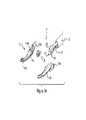
図1〜6を参照すると、本発明の態様とともに使用することができる外科用器具100の一例が種々の図において示されている。図1〜6に示されているように、外科用器具100は、種々の腹腔鏡処置及び開放処置とともに使用するための鉗子として示されている。このようなものとして、器具100は、細長いシャフト102を、シャフト102の遠位端に配置されたエンドエフェクタ104とともに含んでいる。シャフト102及びエンドエフェクタ104は回転エレメント114とカップリングされている。回転エレメントは、使用者がシャフト102とエンドエフェクタ104とをシャフト102の長手方向軸線を中心として回転させるのを可能にし、これにより外科処置部位内におけるエンドエフェクタ104の種々様々な位置(presentation)を可能にする。 With reference to FIGS. 1-6, examples of
ハンドル組立体106は大まかに言えば定置のハンドル部分108と、サムレバー(親指レバー)部分110とを含んでいる。これらは作動機構119と関連して動作することにより、エンドエフェクタ104の運動、物理的係合、及び電気的係合を制御する。ハンドル部分108及びサムレバー部分110のそれぞれは、器具と係合してハンドル組立体106を鋏状の運動で操作するための使用者の指の領域を画定する。このようなものとして、ハンドル部分108に対するサムレバー部分110の運動は、開放位置から閉鎖位置へのエンドエフェクタの運動を容易にする。1実施態様の場合、ハンドル部分108及びサムレバー部分110は、エンドエフェクタ104の単一のアクション運動を可能にする。運動中にハンドル組立体106を選択位置に選択的にロックするために、ラチェット・機構112が含まれている。別の実施態様の場合、いくつかのラチェット・ストッパが含まれているので、使用者は、閉鎖位置、及び/又は組織試料の周りでエンドエフェクタによって加えられる圧力を選択することができる。電気ケーブル組立体116が、電気機械サブ組立体118内の位置から延びており、大まかに言えば外科用器具を電源、例えば下記の無線周波数発電器に接続するために役立つ。電気ケーブル組立体の更なる詳細を以下で説明する。図2は、外科用器具100を斜視図で示しているが、概ね図1に関連して説明したものと同じ形体を示しており、その説明をここで繰り返すことはしない。 Roughly speaking, the
図3A〜3Bは、外科用器具100のエンドエフェクタ104の詳細を示している。図3A〜3Bを引き続き参照すると、エンドエフェクタ104は種々の斜視図において種々の詳細を有する状態で示されている。図3A〜3Bの例では、エンドエフェクタ104はグラスパ/ディセクタ、シーラの組み合わせとして示されている。しかし、本発明の思想及び範囲を逸脱することなしに、種々の他の器具構造を採用することが考えられる。例えば、グラスパの種々の代替構造を採用してよく、また、種々異なる器具、例えばディセクタ又はカッタを、ここに開示されたシーリング態様とともに使用することもできる。エンドエフェクタのサイズ及び全体形状を、本発明の態様に従って構成される装置の他の態様に従って変化させてもよい。 3A-3B show the details of the
図3A〜3Cに示されたグラスパ/ディセクタ、シーラとしてのエンドエフェクタ104に関して、エンドエフェクタ104は、互いに対向するグラスパ部分130及び132を含んでいる。これらのグラスパ部分は、ハンドル組立体108のアクションの結果として開閉するように適合されている。ケーブル122及び124がグラスパ部分130及び132のそれぞれと係合し、これらのケーブルはシャフト102を通ってハンドル組立体108に戻るように延びている。ハンドル組立体108では、ケーブルは電気接続・連結システム118と係合している。引張りブロック126が、ケーブル122及び124をシャフト102の遠位端に固定しており、且つケーブル122及び124のそれぞれをグラスパ部分130及び132とカップリングするための機構を提供する。組み合わせにおいて、この機械的配置は、サムレバー部分110が使用者によって係合されたときに、グラスパ部分130及び132が開閉するのを可能にする。図示のように、グラスパ/シーラ100の実施態様は、グラスパ部分130及び132がサムレバー部分110によって作動されると、単一アクション運動で同時に動くのを可能にする。 With respect to the
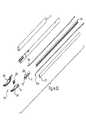
図4〜6Eを参照すると、電気接続・連結システム118の詳細が示されている。全体的に見ると、電気接続・連結システム118は、ハンドル組立体106と、グラスパ部分130及び132によってもたらされる運動との間の機械的インターフェイス、及び電気外科用電源に接続されたケーブル組立体116と、グラスパ部分130及び132との間の電気的インターフェイスの両方を提供する。作動ケーブル151a及び151bは、ジョー部分130及び132から延びていて、ハンドル組立体106へ進められており、ケーブル・カラー150にクリンプされて束縛されている。作動ケーブル151a及び151bの近位端に電気的接続部が形成されている。いくつかの実施態様の場合、作動ケーブル151a及び151bは更に電流をエンドエフェクタ104及び処置を受けている組織へ導く。 With reference to FIGS. 4-6E, the details of the electrical connection /
作動ケーブル151a及び151bはケーブル・カラー150を通って延びている。それぞれのケーブルには、両ケーブルの近位端の近くに、機械的に締め付けられたフェルール・クリンプ部材200a及び200bが接合されている。フェルール・クリンプ部材は、作動ケーブルが(ジョー部分130及び132をクランプ/閉鎖すべく)引かれ且つ(ジョー部分130及び132を開放すべく)押されるのを可能にする。フェルール・クリンプ部材の近くの作動ケーブルの短区分内(符号151aとして示す)では、2つのケーブルのそれぞれが、電気外科用電源ワイヤの2つの極(182及び184)に電気的に接続されている。この接続は付加的な電気的フェルールで行われ(クリンプされ)又ははんだ付けされることができる。これは耐荷重接続ではなく単純に電気的な接続である。電気外科用電源ワイヤは、ケーブル・カラー150の周りに巻き付くことによって、電源ワイヤ又は電気的接続部に過度の歪みをもたらすことなしに、ケーブル・カラーがほぼ丸一回転するのに十分な経路長を提供する。電気外科用トリガ・スイッチの2つの極(188及び186)は、ドーム接点がトリガ152によって押圧されると、フレックス回路142内で閉ループを形成する(図6B参照)。ドーム・スイッチ回路は、作動ケーブル151a及び151bとの電気外科的接続を活性化し、これによりシャフトの長さに沿って電流をグラスパ部分130及び132へ導く。静止状態は、トリガ152が押圧されていないときの開ループであり、電気外科的接続は存在していない。 Activating
器具及びシステムの適切な機能によれば、2つの極は常に電気的に絶縁されたままである。電源ワイヤ182及び184、はんだ付け/クリンプ接続部182a及び182b(図示せず)、151a及び151b、並びにジョー部分130及び132は互いに絶縁されたままでなければならない。図6Dは、シャフト102の長さに沿って作動ケーブルが押出体210によって絶縁され且つ電気絶縁用熱収縮ジャケット212によって外側で密閉されている様子を示している。 According to the proper functioning of the instrument and system, the two poles remain electrically isolated at all times.
図6C及び6Eは、アクチュエータ・ケーブル151a及び151bがインシュレータ220によって分離されている様子と、ジョー部分130及び132がインシュレータ222によって分離されている様子とを示している。押出体210及びインシュレータ220(ジャケット212が外側で軌道を取り囲んでいる)は、アクチュエータ・ケーブルを案内することにより、これらが押され且つ引かれることを可能にする。束縛された軌道は、ジョー部分130及び132を開くために組立体が可撓性ケーブルを押すのを可能にする。 6C and 6E show that the
グラスパ部分130の内面には、一連の非導電性の隆起エレメント134a,134b及び134cが配置されている。これらの隆起エレメントは、グラスパ部分130及び132が閉位置にあるときに、グラスパ部分130及び132の導電性内面が物理的に接触せず、一定の予測可能な相互分離間隔を置いて維持されることを保証する。隆起エレメント134a,134b及び134cは、グラスパ部分130又は132の内面のどちらに位置していてもよい。 A series of non-conductive raised
他の実施態様では、非導電性エレメント134a,134b及び134cは、種々の非導電性材料から形成されていてよい。例えば非導電性エレメントは、セラミック材料、ナイロン、ポリスチレン、ナイロン、シンジオタクチックポリスチレン(SPS)、ポリブチレンテレフタレート(PBT)、ポリカーボネート(PC)、アクリロニトリルブタジエンスチレン(ABS)、ポリフタルアミド(PPA)、ポリイミド、ポリエチレンテレフタレート(PET)、ポリアミド−イミド(PAI)、アクリル(PMMA)、ポリスチレン(PS及びHIPS)、ポリエーテルスルホン(PES)、脂肪族ポリケトン、アセタール(POM)コポリマー、ポリウレタン(PU及びTPU)、ポリフェニレンオキシド分散体を含むナイロン、及びアクリロニトリルスチレンアクリレートから成っていてよい。 In other embodiments, the
ハンドル部分108は外側シェル部分144を含んでいる。外側シェル部分144は、電気接続・連結システム118内部の構成部分のうちのいくつかを取り囲むケーシングの一部を形成している。ケーシングの第2部分が符号146として示されている。ケーシング部分146はサムレバー110に繋がっている。ケーシング部分146の上側部分内には、シャフト・カラー148、ケーブル・カラー150、及び環状ケーブル・カラー154が包囲されている。これらのカラーは、シャフト組立体102をハンドル組立体118全体にアクティブに係合させるために働く。ケーブル組立体116はフレックス回路142とカップリングされている。所定の長さのケーブル140がケーブル組立体116から延びており、ケーブル・カラー150の周りにこれを巻き付けることにより、使用者に対して過度の抵抗を与えずにシャフト組立体102が自由に回転することが可能になる。ハウジング部分144及び146には回転エレメント114がカップリングしており、この回転エレメントは、使用者がシャフト組立体102を回転させ、処置中にエンドエフェクタ104の位置を変更するのを可能にする。 The
種々の締め付け装置、例えばねじ158,160,162,及び164並びにピン156がハンドル組立体の構成部分を互いに固定する。或いは、超音波溶接又はその他の結合技術を利用して、構成部分を互いに固定してもよい。スイッチ152はサムレバー110と係合しており、電気外科用発電器から供給された電力をケーブル組立体116を通して供給することに関与するように適合されている。 Various tightening devices such as
図6A〜6Cは、電源、例えば無線周波数電気外科用発電器と、装置100との間の電気接続を形成し、最終的には電気外科用エネルギーをエンドエフェクタ104へ供給する構成部分を示している。コネクタ170は電気外科用発電器の出力部内に挿入するためにキーを備えている(例えば図7参照)。コネクタ170は、ケーブル組立体116にカップリングされている。ケーブル組立体116の長さは、具体的な用途によって決められるが、電気外科用発電器から離れた位置での器具の操作を可能にするのに十分な長さであることが好ましい。ケーブル組立体116の、コネクタ170とは反対側の端部では、歪み軽減装置180がケーブル組立体116の出口部分190に介在している。 6A-6C show components that form an electrical connection between a power source, eg, a radio frequency electrosurgical generator, and
ケーブル組立体116は4つの導体182,184,186,及び188を収容している。一般に、4つの導体はRF電力をエンドエフェクタ104に提供する導体182及び184、共通/接地導体186、及び識別抵抗器とカップリングするスイッチ導体188である。識別抵抗器は、どのようなタイプの装置が電源内に差し込まれているかに関する概要を信号化する。 The
図7を参照すると、RF発電器300の概略図が示されている。電気外科用エネルギーの供給に関連してRF発電器を使用することが当業者に概ね知られている。しかしながら、低電力・エネルギー供給の機能及びシーケンシングに関連してここで説明する態様は以前に記載されたことはなかった。 With reference to FIG. 7, a schematic diagram of the RF generator 300 is shown. It is generally known to those skilled in the art to use RF generators in connection with the supply of electrosurgical energy. However, the embodiments described herein in relation to the function and sequencing of low power and energy supply have not been previously described.
発電器300は、壁コンセント302からのAC電力を入力し、そのAC電力を電力モジュール304、例えばIECパワーエントリーモジュールに供給する。電力モジュール304はDPDTスイッチ306及び2つの交換可能なヒューズ308のような構成部分を含んでいてよい。電力は電力モジュール304から電力供給ユニット310へ移される。好ましくは医療用途に関連して、電力供給ユニット301は、医療グレード電力供給装置、例えばLambdaのCSS65−24である。DC−DC変換器312及び314が、電力供給ユニット310の24ボルト出力を、電力制御回路のために使用される一対の12ボルト出力に変換する。電力供給ユニット310は次いでバック−ブースト変換器(Buck-Boost Converter)340への入力部320及び330として役立つ。変換器340の出力はHブリッジ回路345へ渡される。Hブリッジ回路345は次いでその信号を共振LCトランスフォーマ回路350へ渡す。トランスフォーマ回路350はキャパシタ352、インデューサ354、及びトランスフォーマ356を含む。1実施態様の場合、トランスフォーマ356は1:9トランスフォーマである。電力はトランスフォーマ356から負荷装置400に供給される。1実施態様の場合、負荷装置400は、図1〜6との関連において上述されたグラスパ/シーラ器具100であり、器具100に供給された電力は、25ワット以下、80ボルトRMS、及び2アンペアRMS未満である。 The generator 300 inputs AC power from the wall outlet 302 and supplies the AC power to the
下記構成部分との関連において、コントローラ360を使用して、負荷装置400に印加されるエネルギーの種々の特徴を検知し、そして脈管シーリング過程に応じてエネルギー特性のうちの1つ又は2つ以上を調節する。負荷装置400(例えば電気外科用器具)には、電流センサ回路390及び電圧センサ回路395がカップリングされている。検知された電流及び電圧に基づいて、演算増幅器(op-amp)392及び394がこれらの値を変換回路380に渡す。変換回路380は電圧RMS−DC変換器382と電流RMS−DC変換器384とを含んでいる。乗算器386及び除算器388が、それぞれ検知された電圧及び電流から電力及びインピーダンスを導き出す。回路382,384,386及び388のそれぞれが、コントローラ360に入力データを提供する。コントローラ360は、次いで種々の入力を処理して分析することによって、脈管シーリング過程の状態を示すことができる。これらの回路382,384,386及び388はバック−ブースト変換器コントローラへの直接的なフィードバック信号として使用されてもよい。 In the context of the following components, the controller 360 is used to detect various characteristics of the energy applied to the loading device 400, and one or more of the energy characteristics depending on the vascular sealing process. To adjust. A
いくつかの実施態様の場合、使用者入力パネル368が含まれていてよい。使用者入力パネル368は、コントローラとのオペレータインタラクションを可能にし、そしてディスプレイ及び何らかの形態の入力装置(例えばキーボード、マウス、ポインタ、ダイアル、又はボタン)を含んでいてよい。コントローラ360からのデータは、アナログ又はデジタル手段、例えばRS−232コネクタ362,プログラミング・ポート364、又はメモリーチップ366を介して出力されることができる。 In some embodiments, a user input panel 368 may be included. The user input panel 368 allows operator interaction with the controller and may include a display and some form of input device (eg, keyboard, mouse, pointer, dial, or button). Data from controller 360 can be output via analog or digital means, such as RS-232
図8は、RF脈管シーリングに適用される既知のインピーダンス曲線を示し、且つ、変化する脈管インピーダンスと、脈管インピーダンスがRF電気外科用シーリング過程中に辿る種々の位相とを示している。図8では、インピーダンスは、外科用装置のジョーに印加される電力の変化に応答している。シーリングされる組織は、完成シールを達成するためにいくつかの変化段階を辿る。従来のシステムは、最小値から変性及び乾燥を経る曲線の立ち上がり区間中のインピーダンスの変化速度を観察し、そしてその変化を制御するために脈管に印加される電力を調節することに基づいて、組織に印加される電流及び電圧をパルス化することにより、シーリング・サイクル中の電力を調節することによって脈管シーリングをもたらした。しかし、これらのシステムは、種々のサイズの脈管に当てはまるような均一な電力供給スキームを適用することはできない。 FIG. 8 shows a known impedance curve applied to RF vascular sealing and shows the changing vascular impedance and the various phases that the vascular impedance follows during the RF electrosurgical sealing process. In FIG. 8, the impedance responds to changes in the power applied to the jaws of the surgical device. The sealed tissue undergoes several stages of change to achieve a finished seal. Traditional systems are based on observing the rate of change of impedance during the rising section of the curve from minimum to degeneration and drying, and adjusting the power applied to the vessel to control that change. Vascular sealing was achieved by adjusting the power during the sealing cycle by pulsing the current and voltage applied to the tissue. However, these systems cannot apply uniform power supply schemes that apply to vessels of various sizes.
電力供給シーケンシング
シーリング過程全体を通して、ジョーに印加された電圧及び電流を測定することによって脈管のインピーダンスをリアルタイムで計算する(Z=V/I)。インピーダンスが規定のフォーマットに従うことが知られているので、電力プロファイル曲線をその設定の次の位相に進ませるようにトリップポイントとして作用するインピーダンス閾値を設定することができる。しかし、時間が経過する前にインピーダンス限界に達しない場合には、曲線は次の位相に進む。それぞれの曲線位相は「OR」論理に従って次の位相に進む。インピーダンス又は時間に基づくパラメータのいずれか1つに達した場合には、電力プロファイルは前進させられる。Power Supply Sequencing Throughout the sealing process, the impedance of the vessel is calculated in real time by measuring the voltage and current applied to the jaws (Z = V / I). Since it is known that the impedance follows a defined format, it is possible to set an impedance threshold that acts as a trip point to advance the power profile curve to the next phase of that setting. However, if the impedance limit is not reached before the lapse of time, the curve advances to the next phase. Each curve phase advances to the next phase according to "OR" logic. The power profile is advanced when either one of the impedance or time-based parameters is reached.
本発明の1つの態様によれば、典型的にはマイクロ外科用途、小児科患者、並びに到達及び/又は視覚化がしばしば困難な外科処置部位における直径6mm未満の血管をシーリングするのに効果的である単一の組のパラメータを実現することが望ましい。 According to one aspect of the invention, it is typically effective in sealing blood vessels less than 6 mm in diameter in microsurgical applications, pediatric patients, and surgical procedures that are often difficult to reach and / or visualize. It is desirable to implement a single set of parameters.
例
下記例は、本発明の態様を例示するものであるが、米国特許法35 U.S.C.§112、欧州特許法第123(2)条、又は説明の妥当性に関連する任意の対応国内法に基づいて、限定的であることはない。これらの例を提供することによって、試験結果の範囲内での変更形、及び相応の実施形及び請求の範囲が、当業者には明らかに且つ一義的に開示されると考えられる。Examples The following examples illustrate aspects of the invention, but are based on 35 USC § 112, 35 USC § 112, European Patent Law Article 123 (2), or any corresponding national law relating to the validity of the description. It is not limited. By providing these examples, it is believed that modifications within the scope of the test results, as well as the corresponding embodiments and claims, will be clearly and uniquely disclosed to those skilled in the art.
脈管シーリング結果
表1は、本発明の態様に基づいて実施された種々のシーリングに伴う電気特性を示す。
表1に記載された試験結果に関連して、電流及び電圧が最大値まで変動するのを許容しつつ電力を一定に保持することにより、例を完成させた。Vmaxが80ボルトRMSに達するか又はインピーダンスが200オームに達したときに電力が解除された。最大電力までの1秒間のランプに続いて2秒間の保持、次いで5ワットの最小電力における1秒間の保持を行うことによって、初期サイクルを確立した。電力があまりにも長く放出されたままの場合には、脈管に印加される追加の電力はインピーダンスを急速に高くする。1つの実施態様の場合、電力は100msec以内に非活性化される。7ワットという低い最大電力で、完全且つ半透明のシールが得られた。 In connection with the test results listed in Table 1, the example was completed by keeping the power constant while allowing the current and voltage to fluctuate to maximum values. Power was released when Vmax reached 80 volt RMS or impedance reached 200 ohms. An initial cycle was established by a 1 second ramp to maximum power followed by a 2 second hold followed by a 1 second hold at a minimum power of 5 watts. If the power remains released for too long, the additional power applied to the vessel will rapidly increase the impedance. In one embodiment, the power is deactivated within 100 msec. A complete and translucent seal was obtained with a low maximum power of 7 watts.
これらの一連の試験に対するPmaxまでの時間は1秒であった。観察によれば、5Wでは十分なシールが提供されず、10W及び15Wの両方では脈管の焦げが示され始めた。半透明であることが必ずしも良好なシールを良好に示すものではないことが判った。いくつかの透明なシールの破裂試験は、所望の500mmHg(ほぼ69kPa(10psi)レベル)には達しなかった。シールのいくつかの焦げは、500mmHg破裂強度に達するより強力なシールを生成するように見えることが判った。次いで一連の30種の試験を行った。ここでは、Pmaxまでの時間を0.5秒に短縮することにより全シーリング時間を短縮し、そして脈管内へのより大きいエネルギーをより迅速に得た。 The time to Pmax for these series of tests was 1 second. Observations showed that 5W did not provide sufficient sealing and both 10W and 15W began to show charring of the vessels. It was found that translucency does not necessarily indicate a good seal. Rupture tests of some clear seals did not reach the desired 500 mmHg (approximately 69 kPa (10 psi) level). It has been found that some charring of the seal appears to produce a stronger seal that reaches a burst strength of 500 mmHg. A series of 30 tests were then performed. Here, the total sealing time was shortened by reducing the time to Pmax to 0.5 seconds, and more energy into the vessel was obtained more quickly.
Pmaxまでの時間を0.5秒間に固定し、Pminまでの時間を0.2秒間に固定した。Pmax及びPminを次いで漸増的に調節することにより、シール結果を最適化した。この試験は12WのPmax及び5WのPminを確立した。この場合、適度で一貫性のあるシールを提供するのに伴ってPminを0ワットと同じくらい低くした。後続の試験では、良好なシールを達成し得る範囲をブラケッティング(bracket)しようと試みた。この範囲は10W〜14Wであった。他の実施態様の場合、Pmax及びPminの範囲は5W〜10W又は2W〜15Wである。 The time to Pmax was fixed at 0.5 seconds and the time to Pmin was fixed at 0.2 seconds. Sealing results were optimized by then adjusting Pmax and Pmin incrementally. This test established a Pmax of 12W and a Pmin of 5W. In this case, Pmin was reduced as low as 0 watts to provide a reasonably consistent seal. Subsequent tests attempted to bracket the extent to which good sealing could be achieved. This range was 10W to 14W. In other embodiments, the range of Pmax and Pmin is 5W-10W or 2W-15W.
第2の例における目標は3秒未満のシーリング時間を可能にすることであった。この実施態様の場合、1.1秒間にわたって12ワット、続いて1.5秒間にわたって5ワットの電力供給を行うことにより良好な結果を得た。これらの設定は、7Wにおけるシーリングが約3秒間かかったという観察に基づいて最初になされた。より短いシーリング時間を所望するならば、より高い電力の設定が必要となることは明らかである。それというのもシールは、脈管に供給された総エネルギーの結果だからである。 The goal in the second example was to allow a sealing time of less than 3 seconds. For this embodiment, good results were obtained by supplying 12 watts for 1.1 seconds followed by 5 watts for 1.5 seconds. These settings were first made based on the observation that sealing at 7W took about 3 seconds. It is clear that higher power settings will be required if shorter sealing times are desired. Because the seal is the result of the total energy supplied to the vessel.
ほぼ100種のシーリング(表1参照)を実施し、様々な結果が得られた。定電力設定において反復可能なシールを得る上での主要な問題点は、ジョー間にしばしばアーキングが発生し、続いて脈管が焼き切られることであった。具体的には、大型の脈管に作用するパラメータを使用して実施される試験を、より小型の脈管に適用した場合、シーリング・サイクルの終了時にしばしばアーキングが生じた。試験では、設定値が単に電力及び時間に依存するのではないことが判った。更なる試験では、下記のインピーダンス閾値、及び電圧及び電流の制限を組み込んだ。 Almost 100 types of sealing (see Table 1) were performed and various results were obtained. A major problem in obtaining a repeatable seal in a constant power setting was the frequent arcing between the jaws, followed by burnout of the vessels. Specifically, when tests performed with parameters that act on large vessels were applied to smaller vessels, arching often occurred at the end of the sealing cycle. Tests have shown that the settings do not simply depend on power and time. Further testing incorporated the following impedance thresholds and voltage and current limits.
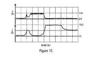
別の例では、インピーダンスのリアルタイム測定に基づいてシーリングを達成した。2.9秒間にわたって7Wのピーク電力で実現可能なシールの例を作成し、続いて2Wの最小電力を維持した。図10及び11は、これらのシールに対するオシロスコープにおける電力出力を示している。ユーザーインターフェイスにおけるインピーダンスの最大出力スケールは200オームである。インピーダンスが200オームに達すると、プログラミングされた入力電力曲線はプロファイルの次の位相に切り換わる。 In another example, sealing was achieved based on real-time measurements of impedance. An example of a seal feasible with a peak power of 7 W was created for 2.9 seconds, followed by a minimum power of 2 W. Figures 10 and 11 show the power output on the oscilloscope for these seals. The maximum output scale of impedance in the user interface is 200 ohms. When the impedance reaches 200 ohms, the programmed input power curve switches to the next phase of the profile.
図10に示されたシーリング中、最大インピーダンスを175オームに設定した。このシーリングは、典型的なバスタブ状のインピーダンス変化曲線に従った。組織は乾き始め、インピーダンスは降下する。組織が乾燥し続けるのに伴って、インピーダンスは急速に上昇する。この場合、インピーダンス閾値に達し、電力をオフにした。 During the sealing shown in FIG. 10, the maximum impedance was set to 175 ohms. This sealing followed a typical bathtub-like impedance change curve. The tissue begins to dry and the impedance drops. Impedance rises rapidly as the tissue continues to dry. In this case, the impedance threshold was reached and the power was turned off.
結論
試験では、僅か7ワットの印加電力で血管の制御されたRFシーリングを達成し得ることが確認された。このようなシーリング中に印加される電圧及び電流はそれぞれ50ボルト未満、0.6A未満であった。使用されるジョーの面積は0.148平方センチメートル(0.023平方インチ)/14.84mm2である。システムによって印加された最大電流密度は、I/A=0.6アンペア/14.84mm2又は0.040A/mm2によって表される。CONCLUSIONS: Tests have confirmed that controlled RF sealing of blood vessels can be achieved with only 7 watts of applied power. The voltage and current applied during such sealing were less than 50 volts and less than 0.6 A, respectively. The area of the jaws used is 0.148 square centimeters (0.023 square inches) /14.84 mm2 . Maximum current density applied by the system are represented by I / A = 0.6 amperes /14.84Mm2 or 0.040A / mm2.
これらの試験及び例は、小さな双極型グラスパ・ジョーエンドエフェクタを利用して、低電力RFエネルギー出力によって最大6mmのサイズの脈管をシーリングし得ることを実証した。このようなシステムのパラメータは、加えられた圧力、電流密度、低い電圧、インピーダンス・モニター及び中点を含む。シーリング工程は、次のもののうちの1つ又は2つ以上を含んでいてよい。
a.器具ジョーを0.013センチメートル(0.005インチ)以下に圧縮するのに十分な圧力を組織に加える。また、この圧力は、組織が加熱中に収縮するとき、ジョーが撓むことがなく且つジョー間のギャップが一定に保たれるほど十分に高くなければならない。試験データは、この所要圧力が448.5kPa〜759kPa(65〜110lb/in2)であることを示している。別の実施態様の場合、所要圧力は最大約862.5kPa(125lb/in2)であってよい。
b.次いで、電流密度が0.034〜0.1アンペア/mm2となるように、組織に無線周波数電流を印加する。この電流は、内弾性板が融合するように組織を迅速に加熱するのに十分な量である。このことが生じるためには、約140℃の温度が必要となる。
c.この電流密度を供給するための発電器からの電力供給量は、概ね20ワット未満であるが、35ワットの高さであってもよい。電力が高ければ高いほどシーリング時間を短縮することができる。
d.組織が乾燥し始めたら、電力を60〜80%だけ低減してよい。そしてシャットオフ前に所定の時間にわたって加熱を続ける。組織インピーダンスが150〜250オームのレベルに達したとき又は設定時間間隔を置いて、電力を低減することができる。
e.システムの電圧を100ボルトRMS未満に制限し、そしてピーク電圧を典型的には85ボルトRMSの範囲にする。
f.上記工程間に、1つ又は2つ以上の待機状態を挿入してもよい。These tests and examples demonstrated that a small bipolar Graspa jaw end effector could be utilized to seal vessels up to 6 mm in size with low power RF energy output. The parameters of such a system include applied pressure, current density, low voltage, impedance monitor and midpoint. The sealing step may include one or more of the following:
a. Apply sufficient pressure to the tissue to compress the instrument jaws below 0.013 cm (0.005 inch). Also, this pressure must be high enough that the jaws do not bend and the gap between the jaws remains constant as the tissue contracts during heating. Test data show that this required pressure is between 448.5 kPa and 759 kPa (65-110 lb / in2 ). In another embodiment, the required pressure may be up to about 862.5 kPa (125 lb / in2 ).
b. A radio frequency current is then applied to the tissue so that the current density is 0.034 to 0.1 amps / mm2. This current is sufficient to quickly heat the tissue so that the internal elastic plates fuse. A temperature of about 140 ° C. is required for this to occur.
c. The amount of power supplied by the generator to supply this current density is generally less than 20 watts, but may be as high as 35 watts. The higher the power, the shorter the sealing time.
d. Once the tissue begins to dry, the power may be reduced by 60-80%. Then, heating is continued for a predetermined time before shutting off. Power can be reduced when the tissue impedance reaches a level of 150-250 ohms or at set time intervals.
e. Limit the system voltage to less than 100 volt RMS, and limit the peak voltage to typically the 85 volt RMS range.
f. One or more standby states may be inserted between the steps.
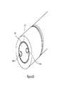
実証されたように、ジョーのサイズを制限し、そして高い圧力を加えることによって、低電力システムを使用して脈管をシーリングすることができる。幅が約3mm、長さが10〜12mmであり、断面積が約15〜22mm2であるジョーが好ましいが、他の幾何学的形状も考えられる。図9は、本発明の態様との関連において使用されるエンドエフェクタのジョーの幾何学的形状、例えばメリーランド様式のジョー(Maryland style jaw)の1実施態様を示している。図9に示されたジョーの表面積を記述する場合、実際に互いに整合して、シーリングされる組織の周りを把持するジョーの表面積を参照する。いくつかの実施態様の場合、ジョー表面には湾曲面又はテーパ縁が設けられていて、これらはシール機能の大部分を実際には発揮しない。ジョー表面積を記述する場合には、シール面の通常の範囲外にあるこれらのジョー部分を含まないものとする。ここに記載される電力供給スキームとの組み合わせにおいて、システムは、標準的な双極型のシーリング・システムに対して所要電力を著しく低減する。いくつかの実施態様における所要電力は10〜35ワットである。As demonstrated, by limiting the size of the jaws and applying high pressure, a low power system can be used to seal the vessels. A jaw having a width of about 3 mm, a length of 10 to 12 mm and a cross-sectional area of about 15 to 22 mm2 is preferred, but other geometric shapes are also conceivable. FIG. 9 shows one embodiment of a jaw geometry of an end effector used in the context of aspects of the invention, eg, a Maryland style jaw. When describing the surface area of the jaws shown in FIG. 9, we refer to the surface area of the jaws that actually align with each other and grip around the tissue to be sealed. In some embodiments, the jaw surface is provided with curved or tapered edges that do not actually perform most of the sealing function. When describing the jaw surface area, it is assumed that these jaw portions outside the normal range of the sealing surface are not included. In combination with the power supply schemes described herein, the system significantly reduces power requirements compared to standard bipolar sealing systems. The required power in some embodiments is 10-35 watts.
他の試験の態様によれば、非導電性スペーサ、例えばセラミック・ビードを器具内に組み込むことにより、ジョーを相互接触する前に停止させ、電気システム内の短絡を防止した。動作中のジョーがビードの頂部に着地するので、セラミック・ビードはジョーを平行に保つ手段も提供した。 According to other aspects of the test, non-conductive spacers, such as ceramic beads, were incorporated into the appliance to stop the jaws before they came into contact with each other and prevent short circuits in the electrical system. The ceramic bead also provided a means to keep the jaws parallel, as the moving jaws landed on the top of the beads.
試験環境において、非導電性であってシーリング中に溶融することのない縫合糸(直径0.015cm(0.006インチ))を利用して、ジョー表面間の分離状態を維持し、アーキングを防止した。表1に記載された例では、縫合糸を上側ジョーに巻き付けたので、ジョーはばねによって閉じられたときに0.015cm(0.006インチ)だけ分離されることになる。 In the test environment, sutures (0.015 cm (0.006 inch) in diameter) that are non-conductive and do not melt during sealing are used to maintain separation between jaw surfaces and prevent arcing. bottom. In the example shown in Table 1, the suture was wound around the upper jaw so that the jaws would be separated by 0.015 cm (0.006 inch) when closed by the spring.
別の例によれば、非導電性縫合糸を所定の場所に配置した状態で、電力を公称開始点として12Wに設定し、10W〜14Wをブラケッティングした。全ジョーバイトがシーリングされる(ジョーが組織で100%充填される)と、最小限の粘着及び焦げしか伴わずに高品質のシール、すなわち優れた半透明性が得られた。しかしながら、ジョーへの充填率が低い(50〜75%)より小型の脈管に対してこれらの設定値を用いてシーリングを実施しようとすると、アーキングがまだ発生した。追加の試験では、Pmax7W〜15Wをブラケッティングした。Pminは5Wに設定し、4W〜7Wをブラケッティングした。電力及び時間以外のパラメータに制御制限がないので、より低い電力設定値を用いて、ジョーへの組織充填率が50〜80%であるより小さな脈管に適度なシーリングを生成した。ジョーへの脈管充填率が100%である場合、7Wはシーリングするには十分ではなく、これらのより大型の脈管を十分にシーリングするためには、12W近くのより高い電力が必要であった。 According to another example, with the non-conductive sutures in place, the power was set to 12 W as the nominal starting point and 10 W to 14 W was bracketed. When all jawbites were sealed (the jaws were 100% filled with tissue), a high quality seal, i.e. excellent translucency, was obtained with minimal adhesion and charring. However, arching still occurred when attempting to perform sealing with these settings for smaller vessels with lower jaw filling (50-75%). In additional tests,
他の例によれば、ユーザーインターフェイスにインピーダンス閾値を設定することにより、更なるシールを提供した。この場合、電力曲線にブレークポイントを設定することが可能であった。これらのブレークポイントは、インピーダンスのリアルタイムでの上昇を観察することによって、ジョーに供給される電力を制限することができた。電力及び時間を唯一の電力曲線変更子として用いて追加のシーリングを行った。電力供給のシーケンス及び制御に加えられたインピーダンス・トリガ点によって、発電器がインピーダンスの変化に迅速に応答して必要な調節を施すことが可能になった。 According to another example, setting an impedance threshold on the user interface provided an additional seal. In this case, it was possible to set a breakpoint on the power curve. These breakpoints were able to limit the power supplied to the jaws by observing a real-time rise in impedance. Additional sealing was performed using power and time as the only power curve modifier. Impedance trigger points added to the sequence and control of the power supply allowed the generator to respond quickly to changes in impedance and make the necessary adjustments.
電流及び電圧のクランプ
装置の試験の別の態様において、電流及び電圧の制限を実施した。観察に基づいて述べるならば、100Vまで電圧を制限することによって、アーキングが2〜7mm幅の脈管において排除された。これらのパラメータは、任意のパーセンテージでジョーに充填された脈管をシーリングすることを可能にし、ひいてはこの方法及び装置は、組織材料をジョーに完全充填したものに限定されることはなかった。実験検証として、電圧制限を150ボルトに上げると、再びアーキングが発生した。このことは、電圧制限がアーキング発生を正しく阻止することを立証した。次に実施される一連のシーリングのために、電圧最大値を75〜100ボルトに設定した。Current and Voltage Clamping In another aspect of testing the device, current and voltage limiting was performed. Based on observation, by limiting the voltage to 100 V, the arcing was eliminated in the 2-7 mm wide vessels. These parameters made it possible to seal the vessels filled in the jaws at any percentage, and thus the methods and devices were not limited to those in which the jaws were completely filled with tissue material. As an experimental verification, when the voltage limit was raised to 150 volts, arcing occurred again. This proved that the voltage limit correctly prevented the occurrence of arcing. The maximum voltage was set to 75-100 volts for the next series of sealings.
シーリングのための最大電流を決める別の方法として、システム・エネルギーチェックを実施することによって、ジョー間に配置された生理食塩水をボイルオフするためにどのような電流レベルが必要となるかを観察した。RF電力がジョーに印加されたときに生理食塩水を蒸気にして蒸発させ始めるために1.8Aが必要であることが判り、これをシーリングのための最大電流として使用した。 Another way to determine the maximum current for sealing was to perform a system energy check to observe what current level would be needed to boil off the saline placed between the jaws. .. It was found that 1.8 A was required to vaporize the saline solution when RF power was applied to the jaws and begin to evaporate, which was used as the maximum current for sealing.
別の例において、電流の大量流入によるエネルギーの高速印加が良好なシールを形成することが判った。例は、Pminが5Wに設定された低エネルギーの1秒間の破裂を伴う高電流エネルギーに従うことを含んだ。 In another example, it was found that high speed application of energy due to a large inflow of current forms a good seal. Examples included following high current energy with a low energy burst for 1 second with Pmin set to 5W.
別の例では長さ1.039cm(0.409インチ)の一組のジョーをシステム内に取り付けた。古いジョーを除去し、これらは電圧制限が設定されていない間に被ったアーキングに起因して著しいピッティング(pitting)が形成されていることが判った。元のジョーよりも長いことに加えて、ジョーの上縁によって、シャープな縁部とともに発生し得る、シャープな角隅の効果及び高電流集中を軽減しやすくなった。 In another example, a set of jaws 1.039 cm (0.409 inches) long was installed in the system. The old jaws were removed and it was found that they formed significant pitting due to the arcing they suffered while the voltage limit was not set. In addition to being longer than the original jaws, the upper edge of the jaws helps reduce the sharp corner effects and high current concentration that can occur with sharp edges.
別の例では、75ボルトに設定されたVmax及び1.8Aに設定されたImaxを用いてシールを形成した。後続のシールには、いかなるアーキングのインシデントも決して観察されなかった。シールは以下の組のパラメータで形成された。
− Pmax=15W
− Pmaxにおける時間=2.5秒
− Pmin=5W
− Pminにおける時間=1秒
− Vmax=75V
− Imax=1.8A
− Pmaxまでの時間=0.01
− PmaxからPminまでの時間=0.01秒In another example, a seal was formed with Vmax set at 75 volts and Imax set at 1.8A. No incidents of any arcing were observed on subsequent seals. The seal was formed with the following set of parameters.
− Pmax = 15W
-Time at Pmax = 2.5 seconds-Pmin = 5W
-Time in Pmin = 1 second-Vmax = 75V
− Imax = 1.8A
-Time to Pmax = 0.01
− Time from Pmax to Pmin = 0.01 seconds
一連の32種のシーリングを2匹の動物において実施した。脈管は2mm〜6mm幅であった。この一連の32種のシーリングのうち20種を破裂試験した。全てのシールが360mmHgの最小値に耐えることに成功した。同じ設定を用いて腸間膜組織でもシーリングを成功裡に実施した。 A series of 32 species of sealing was performed on 2 animals. The vessels were 2 mm to 6 mm wide. Twenty of the 32 seals in this series were ruptured. All seals succeeded in withstanding a minimum value of 360 mmHg. Successful sealing was also performed on the mesenteric tissue using the same settings.
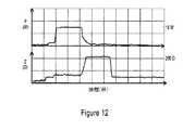
図10〜14は、3つの異なるシールに対して捕捉されたオシロスコープ軌跡の再現を示している。上記設定を用いて全てをシーリングした。全て、インピーダンス閾値を200オームとして設定した。電力がスイッチオフするようにトリガされたときにこれを観察することによって、シーリング時間を割り出した。図11は、シーリング時間が1.5秒間の3.5mm脈管についての結果を示している。図12は、シーリング時間が2.3秒間の5mm脈管についての血管を示している。図13は、シーリング時間が0.75秒間の1.5mm脈管についての血管を示している。 Figures 10-14 show the reproduction of captured oscilloscope trajectories for three different seals. Everything was sealed using the above settings. In all cases, the impedance threshold was set to 200 ohms. The sealing time was determined by observing this when the power was triggered to switch off. FIG. 11 shows the results for a 3.5 mm vessel with a sealing time of 1.5 seconds. FIG. 12 shows blood vessels for a 5 mm vessel with a sealing time of 2.3 seconds. FIG. 13 shows blood vessels for a 1.5 mm vessel with a sealing time of 0.75 seconds.
図14は、付加的なシーリング例に対して捕捉されたオシロスコープ軌跡の再現を示している。最大インピーダンスは175オームに設定した。シーリングのこのインピーダンスは典型的なインピーダンス変化曲線に従った。シーリング過程中、組織は乾き始め、そしてインピーダンスが降下する。組織が乾燥し続けるのに伴って、インピーダンスは急速に上昇する。この場合、インピーダンス閾値に達し、そして実行継続のためにPmaxをPminに切り換えた。 FIG. 14 shows a reproduction of the captured oscilloscope trajectory for an additional sealing example. The maximum impedance was set to 175 ohms. This impedance of the ceiling followed a typical impedance change curve. During the sealing process, the tissue begins to dry and the impedance drops. Impedance rises rapidly as the tissue continues to dry. In this case, the impedance threshold was reached and Pmax was switched to Pmin to continue execution.
当業者には容易に明らかなように、本発明、その利用、及びその形態において数多くの変更及び置換を施すことによって、本明細書中に記載された実施態様によって達成されるものと実質的に同じ結果を達成することができる。従って、開示された模範形態に本発明を限定しようという意図はない。数多くの変更形、改変形、及び代替構造が、請求項に示された本開示発明の範囲及び思想に含まれる。 As will be readily apparent to those skilled in the art, by making numerous modifications and substitutions in the present invention, its use, and embodiments thereof, substantially as achieved by the embodiments described herein. The same result can be achieved. Therefore, there is no intention to limit the present invention to the disclosed exemplary forms. A number of modifications, modifications, and alternative structures are included in the scope and ideas of the disclosed invention as set forth in the claims.
Claims (8)
Translated fromJapaneseエンドエフェクタに動作可能に結合された電源と、
一対のジョーであって、該一対のジョーの間に配置された組織に作用を及ぼすための一対のジョーを有する、前記エンドエフェクタと、を備え、
前記電源は、バック−ブースト変換器に第1の信号および第2の信号を入力するように構成されており、
前記バック−ブースト変換器は、出力をHブリッジ回路に送信するように構成されており、
前記Hブリッジ回路は、スイッチングによって矩形波信号を生成し、かつ該矩形波信号を共振LCトランスフォーマ回路に渡すように構成されており、
前記電源は、電力信号を送信するように構成されており、
前記一対のジョーは、電力信号を受信するために電源に動作可能に結合され、その電力は、電流及び電圧がそれぞれの最大値まで変動するのを許容しつつ、一定に保持され、
前記電力は、一対のジョーの間に位置する組織を3秒以内にシーリングするように構成されている、
器具。An instrument for electrosurgery
With a power supply operably coupled to the end effector,
The end effector, which is a pair of jaws and has a pair of jaws for acting on a tissue arranged between the pair of jaws.
The power supply is configured to input a first signal and a second signal to the back-boost converter.
The back-boost converter is configured to transmit its output to an H-bridge circuit.
The H-bridge circuit isconfigured to generate a square wave signal by switching and pass the square wave signal to a resonant LC transformer circuit.
The power supply is configured to transmit power signals.
The pair of jaws are operably coupled to a power source to receive a power signal, the power of which is kept constant, allowing current and voltage to fluctuate to their respective maximum values.
The power is configured to seal the tissue located between the pair of jaws within 3 seconds.
Instrument.
Applications Claiming Priority (5)
| Application Number | Priority Date | Filing Date | Title |
|---|---|---|---|
| US35211410P | 2010-06-07 | 2010-06-07 | |
| US61/352,114 | 2010-06-07 | ||
| US13/153,513 | 2011-06-06 | ||
| US13/153,513US9144455B2 (en) | 2010-06-07 | 2011-06-06 | Low power tissue sealing device and method |
| JP2018016961AJP6483878B2 (en) | 2010-06-07 | 2018-02-02 | Apparatus and method for sealing tissue with low power |
Related Parent Applications (1)
| Application Number | Title | Priority Date | Filing Date |
|---|---|---|---|
| JP2018016961ADivisionJP6483878B2 (en) | 2010-06-07 | 2018-02-02 | Apparatus and method for sealing tissue with low power |
Publications (2)
| Publication Number | Publication Date |
|---|---|
| JP2019084380A JP2019084380A (en) | 2019-06-06 |
| JP6940537B2true JP6940537B2 (en) | 2021-09-29 |
Family
ID=45098385
Family Applications (4)
| Application Number | Title | Priority Date | Filing Date |
|---|---|---|---|
| JP2013514276AActiveJP6309762B2 (en) | 2010-06-07 | 2011-06-07 | Apparatus and method for sealing tissue with low power |
| JP2016015986AActiveJP6363635B2 (en) | 2010-06-07 | 2016-01-29 | Apparatus and method for sealing tissue with low power |
| JP2018016961AActiveJP6483878B2 (en) | 2010-06-07 | 2018-02-02 | Apparatus and method for sealing tissue with low power |
| JP2019024359AActiveJP6940537B2 (en) | 2010-06-07 | 2019-02-14 | Equipment and methods for sealing tissues with low power |
Family Applications Before (3)
| Application Number | Title | Priority Date | Filing Date |
|---|---|---|---|
| JP2013514276AActiveJP6309762B2 (en) | 2010-06-07 | 2011-06-07 | Apparatus and method for sealing tissue with low power |
| JP2016015986AActiveJP6363635B2 (en) | 2010-06-07 | 2016-01-29 | Apparatus and method for sealing tissue with low power |
| JP2018016961AActiveJP6483878B2 (en) | 2010-06-07 | 2018-02-02 | Apparatus and method for sealing tissue with low power |
Country Status (4)
| Country | Link |
|---|---|
| US (6) | US9144455B2 (en) |
| EP (2) | EP2575660B1 (en) |
| JP (4) | JP6309762B2 (en) |
| WO (1) | WO2011156310A1 (en) |
Families Citing this family (446)
| Publication number | Priority date | Publication date | Assignee | Title |
|---|---|---|---|---|
| US9060770B2 (en) | 2003-05-20 | 2015-06-23 | Ethicon Endo-Surgery, Inc. | Robotically-driven surgical instrument with E-beam driver |
| US20070084897A1 (en) | 2003-05-20 | 2007-04-19 | Shelton Frederick E Iv | Articulating surgical stapling instrument incorporating a two-piece e-beam firing mechanism |
| US8215531B2 (en) | 2004-07-28 | 2012-07-10 | Ethicon Endo-Surgery, Inc. | Surgical stapling instrument having a medical substance dispenser |
| US11998198B2 (en) | 2004-07-28 | 2024-06-04 | Cilag Gmbh International | Surgical stapling instrument incorporating a two-piece E-beam firing mechanism |
| US9072535B2 (en) | 2011-05-27 | 2015-07-07 | Ethicon Endo-Surgery, Inc. | Surgical stapling instruments with rotatable staple deployment arrangements |
| US11890012B2 (en) | 2004-07-28 | 2024-02-06 | Cilag Gmbh International | Staple cartridge comprising cartridge body and attached support |
| US7669746B2 (en) | 2005-08-31 | 2010-03-02 | Ethicon Endo-Surgery, Inc. | Staple cartridges for forming staples having differing formed staple heights |
| US9237891B2 (en) | 2005-08-31 | 2016-01-19 | Ethicon Endo-Surgery, Inc. | Robotically-controlled surgical stapling devices that produce formed staples having different lengths |
| US7934630B2 (en) | 2005-08-31 | 2011-05-03 | Ethicon Endo-Surgery, Inc. | Staple cartridges for forming staples having differing formed staple heights |
| US11246590B2 (en) | 2005-08-31 | 2022-02-15 | Cilag Gmbh International | Staple cartridge including staple drivers having different unfired heights |
| US10159482B2 (en) | 2005-08-31 | 2018-12-25 | Ethicon Llc | Fastener cartridge assembly comprising a fixed anvil and different staple heights |
| US11484312B2 (en) | 2005-08-31 | 2022-11-01 | Cilag Gmbh International | Staple cartridge comprising a staple driver arrangement |
| US20070106317A1 (en) | 2005-11-09 | 2007-05-10 | Shelton Frederick E Iv | Hydraulically and electrically actuated articulation joints for surgical instruments |
| US20120292367A1 (en) | 2006-01-31 | 2012-11-22 | Ethicon Endo-Surgery, Inc. | Robotically-controlled end effector |
| US20110295295A1 (en) | 2006-01-31 | 2011-12-01 | Ethicon Endo-Surgery, Inc. | Robotically-controlled surgical instrument having recording capabilities |
| US11224427B2 (en) | 2006-01-31 | 2022-01-18 | Cilag Gmbh International | Surgical stapling system including a console and retraction assembly |
| US11793518B2 (en) | 2006-01-31 | 2023-10-24 | Cilag Gmbh International | Powered surgical instruments with firing system lockout arrangements |
| US20110024477A1 (en) | 2009-02-06 | 2011-02-03 | Hall Steven G | Driven Surgical Stapler Improvements |
| US8708213B2 (en) | 2006-01-31 | 2014-04-29 | Ethicon Endo-Surgery, Inc. | Surgical instrument having a feedback system |
| US8186555B2 (en) | 2006-01-31 | 2012-05-29 | Ethicon Endo-Surgery, Inc. | Motor-driven surgical cutting and fastening instrument with mechanical closure system |
| US11278279B2 (en) | 2006-01-31 | 2022-03-22 | Cilag Gmbh International | Surgical instrument assembly |
| US7845537B2 (en) | 2006-01-31 | 2010-12-07 | Ethicon Endo-Surgery, Inc. | Surgical instrument having recording capabilities |
| US7753904B2 (en) | 2006-01-31 | 2010-07-13 | Ethicon Endo-Surgery, Inc. | Endoscopic surgical instrument with a handle that can articulate with respect to the shaft |
| US8820603B2 (en) | 2006-01-31 | 2014-09-02 | Ethicon Endo-Surgery, Inc. | Accessing data stored in a memory of a surgical instrument |
| US8992422B2 (en) | 2006-03-23 | 2015-03-31 | Ethicon Endo-Surgery, Inc. | Robotically-controlled endoscopic accessory channel |
| US8322455B2 (en) | 2006-06-27 | 2012-12-04 | Ethicon Endo-Surgery, Inc. | Manually driven surgical cutting and fastening instrument |
| US10568652B2 (en) | 2006-09-29 | 2020-02-25 | Ethicon Llc | Surgical staples having attached drivers of different heights and stapling instruments for deploying the same |
| US7506791B2 (en) | 2006-09-29 | 2009-03-24 | Ethicon Endo-Surgery, Inc. | Surgical stapling instrument with mechanical mechanism for limiting maximum tissue compression |
| US11980366B2 (en) | 2006-10-03 | 2024-05-14 | Cilag Gmbh International | Surgical instrument |
| US8632535B2 (en) | 2007-01-10 | 2014-01-21 | Ethicon Endo-Surgery, Inc. | Interlock and surgical instrument including same |
| US8684253B2 (en) | 2007-01-10 | 2014-04-01 | Ethicon Endo-Surgery, Inc. | Surgical instrument with wireless communication between a control unit of a robotic system and remote sensor |
| US11291441B2 (en) | 2007-01-10 | 2022-04-05 | Cilag Gmbh International | Surgical instrument with wireless communication between control unit and remote sensor |
| US8652120B2 (en) | 2007-01-10 | 2014-02-18 | Ethicon Endo-Surgery, Inc. | Surgical instrument with wireless communication between control unit and sensor transponders |
| US20080169333A1 (en) | 2007-01-11 | 2008-07-17 | Shelton Frederick E | Surgical stapler end effector with tapered distal end |
| US11039836B2 (en) | 2007-01-11 | 2021-06-22 | Cilag Gmbh International | Staple cartridge for use with a surgical stapling instrument |
| US7673782B2 (en) | 2007-03-15 | 2010-03-09 | Ethicon Endo-Surgery, Inc. | Surgical stapling instrument having a releasable buttress material |
| US8893946B2 (en) | 2007-03-28 | 2014-11-25 | Ethicon Endo-Surgery, Inc. | Laparoscopic tissue thickness and clamp load measuring devices |
| US11564682B2 (en) | 2007-06-04 | 2023-01-31 | Cilag Gmbh International | Surgical stapler device |
| US8931682B2 (en) | 2007-06-04 | 2015-01-13 | Ethicon Endo-Surgery, Inc. | Robotically-controlled shaft based rotary drive systems for surgical instruments |
| US7753245B2 (en) | 2007-06-22 | 2010-07-13 | Ethicon Endo-Surgery, Inc. | Surgical stapling instruments |
| US11849941B2 (en) | 2007-06-29 | 2023-12-26 | Cilag Gmbh International | Staple cartridge having staple cavities extending at a transverse angle relative to a longitudinal cartridge axis |
| US8636736B2 (en) | 2008-02-14 | 2014-01-28 | Ethicon Endo-Surgery, Inc. | Motorized surgical cutting and fastening instrument |
| US11986183B2 (en) | 2008-02-14 | 2024-05-21 | Cilag Gmbh International | Surgical cutting and fastening instrument comprising a plurality of sensors to measure an electrical parameter |
| US7819298B2 (en) | 2008-02-14 | 2010-10-26 | Ethicon Endo-Surgery, Inc. | Surgical stapling apparatus with control features operable with one hand |
| US9179912B2 (en) | 2008-02-14 | 2015-11-10 | Ethicon Endo-Surgery, Inc. | Robotically-controlled motorized surgical cutting and fastening instrument |
| US8573465B2 (en) | 2008-02-14 | 2013-11-05 | Ethicon Endo-Surgery, Inc. | Robotically-controlled surgical end effector system with rotary actuated closure systems |
| US8758391B2 (en) | 2008-02-14 | 2014-06-24 | Ethicon Endo-Surgery, Inc. | Interchangeable tools for surgical instruments |
| US7866527B2 (en) | 2008-02-14 | 2011-01-11 | Ethicon Endo-Surgery, Inc. | Surgical stapling apparatus with interlockable firing system |
| JP5410110B2 (en) | 2008-02-14 | 2014-02-05 | エシコン・エンド−サージェリィ・インコーポレイテッド | Surgical cutting / fixing instrument with RF electrode |
| US11272927B2 (en) | 2008-02-15 | 2022-03-15 | Cilag Gmbh International | Layer arrangements for surgical staple cartridges |
| US9585657B2 (en) | 2008-02-15 | 2017-03-07 | Ethicon Endo-Surgery, Llc | Actuator for releasing a layer of material from a surgical end effector |
| US9005230B2 (en) | 2008-09-23 | 2015-04-14 | Ethicon Endo-Surgery, Inc. | Motorized surgical instrument |
| US11648005B2 (en) | 2008-09-23 | 2023-05-16 | Cilag Gmbh International | Robotically-controlled motorized surgical instrument with an end effector |
| US9386983B2 (en) | 2008-09-23 | 2016-07-12 | Ethicon Endo-Surgery, Llc | Robotically-controlled motorized surgical instrument |
| US8210411B2 (en) | 2008-09-23 | 2012-07-03 | Ethicon Endo-Surgery, Inc. | Motor-driven surgical cutting instrument |
| US8608045B2 (en) | 2008-10-10 | 2013-12-17 | Ethicon Endo-Sugery, Inc. | Powered surgical cutting and stapling apparatus with manually retractable firing system |
| US8517239B2 (en) | 2009-02-05 | 2013-08-27 | Ethicon Endo-Surgery, Inc. | Surgical stapling instrument comprising a magnetic element driver |
| RU2525225C2 (en) | 2009-02-06 | 2014-08-10 | Этикон Эндо-Серджери, Инк. | Improvement of drive surgical suturing instrument |
| US8444036B2 (en) | 2009-02-06 | 2013-05-21 | Ethicon Endo-Surgery, Inc. | Motor driven surgical fastener device with mechanisms for adjusting a tissue gap within the end effector |
| US8220688B2 (en) | 2009-12-24 | 2012-07-17 | Ethicon Endo-Surgery, Inc. | Motor-driven surgical cutting instrument with electric actuator directional control assembly |
| US8851354B2 (en) | 2009-12-24 | 2014-10-07 | Ethicon Endo-Surgery, Inc. | Surgical cutting instrument that analyzes tissue thickness |
| US9144455B2 (en) | 2010-06-07 | 2015-09-29 | Just Right Surgical, Llc | Low power tissue sealing device and method |
| US8783543B2 (en) | 2010-07-30 | 2014-07-22 | Ethicon Endo-Surgery, Inc. | Tissue acquisition arrangements and methods for surgical stapling devices |
| US10945731B2 (en) | 2010-09-30 | 2021-03-16 | Ethicon Llc | Tissue thickness compensator comprising controlled release and expansion |
| US9629814B2 (en) | 2010-09-30 | 2017-04-25 | Ethicon Endo-Surgery, Llc | Tissue thickness compensator configured to redistribute compressive forces |
| US9351730B2 (en) | 2011-04-29 | 2016-05-31 | Ethicon Endo-Surgery, Llc | Tissue thickness compensator comprising channels |
| US11925354B2 (en) | 2010-09-30 | 2024-03-12 | Cilag Gmbh International | Staple cartridge comprising staples positioned within a compressible portion thereof |
| US9788834B2 (en) | 2010-09-30 | 2017-10-17 | Ethicon Llc | Layer comprising deployable attachment members |
| US9386988B2 (en) | 2010-09-30 | 2016-07-12 | Ethicon End-Surgery, LLC | Retainer assembly including a tissue thickness compensator |
| US11812965B2 (en) | 2010-09-30 | 2023-11-14 | Cilag Gmbh International | Layer of material for a surgical end effector |
| US9016542B2 (en) | 2010-09-30 | 2015-04-28 | Ethicon Endo-Surgery, Inc. | Staple cartridge comprising compressible distortion resistant components |
| US9232941B2 (en) | 2010-09-30 | 2016-01-12 | Ethicon Endo-Surgery, Inc. | Tissue thickness compensator comprising a reservoir |
| US12213666B2 (en) | 2010-09-30 | 2025-02-04 | Cilag Gmbh International | Tissue thickness compensator comprising layers |
| US9364233B2 (en) | 2010-09-30 | 2016-06-14 | Ethicon Endo-Surgery, Llc | Tissue thickness compensators for circular surgical staplers |
| US11298125B2 (en) | 2010-09-30 | 2022-04-12 | Cilag Gmbh International | Tissue stapler having a thickness compensator |
| US8695866B2 (en) | 2010-10-01 | 2014-04-15 | Ethicon Endo-Surgery, Inc. | Surgical instrument having a power control circuit |
| US9039694B2 (en) | 2010-10-22 | 2015-05-26 | Just Right Surgical, Llc | RF generator system for surgical vessel sealing |
| AU2012250197B2 (en) | 2011-04-29 | 2017-08-10 | Ethicon Endo-Surgery, Inc. | Staple cartridge comprising staples positioned within a compressible portion thereof |
| US11207064B2 (en) | 2011-05-27 | 2021-12-28 | Cilag Gmbh International | Automated end effector component reloading system for use with a robotic system |
| US9044230B2 (en) | 2012-02-13 | 2015-06-02 | Ethicon Endo-Surgery, Inc. | Surgical cutting and fastening instrument with apparatus for determining cartridge and firing motion status |
| BR112014024098B1 (en) | 2012-03-28 | 2021-05-25 | Ethicon Endo-Surgery, Inc. | staple cartridge |
| JP6224070B2 (en) | 2012-03-28 | 2017-11-01 | エシコン・エンド−サージェリィ・インコーポレイテッドEthicon Endo−Surgery,Inc. | Retainer assembly including tissue thickness compensator |
| MX358135B (en) | 2012-03-28 | 2018-08-06 | Ethicon Endo Surgery Inc | Tissue thickness compensator comprising a plurality of layers. |
| US9788851B2 (en) | 2012-04-18 | 2017-10-17 | Ethicon Llc | Surgical instrument with tissue density sensing |
| US9101358B2 (en) | 2012-06-15 | 2015-08-11 | Ethicon Endo-Surgery, Inc. | Articulatable surgical instrument comprising a firing drive |
| US20140005718A1 (en) | 2012-06-28 | 2014-01-02 | Ethicon Endo-Surgery, Inc. | Multi-functional powered surgical device with external dissection features |
| US20140001231A1 (en) | 2012-06-28 | 2014-01-02 | Ethicon Endo-Surgery, Inc. | Firing system lockout arrangements for surgical instruments |
| BR112014032776B1 (en) | 2012-06-28 | 2021-09-08 | Ethicon Endo-Surgery, Inc | SURGICAL INSTRUMENT SYSTEM AND SURGICAL KIT FOR USE WITH A SURGICAL INSTRUMENT SYSTEM |
| US9289256B2 (en) | 2012-06-28 | 2016-03-22 | Ethicon Endo-Surgery, Llc | Surgical end effectors having angled tissue-contacting surfaces |
| US12383267B2 (en) | 2012-06-28 | 2025-08-12 | Cilag Gmbh International | Robotically powered surgical device with manually-actuatable reversing system |
| JP6290201B2 (en) | 2012-06-28 | 2018-03-07 | エシコン・エンド−サージェリィ・インコーポレイテッドEthicon Endo−Surgery,Inc. | Lockout for empty clip cartridge |
| US9408606B2 (en) | 2012-06-28 | 2016-08-09 | Ethicon Endo-Surgery, Llc | Robotically powered surgical device with manually-actuatable reversing system |
| US9282974B2 (en) | 2012-06-28 | 2016-03-15 | Ethicon Endo-Surgery, Llc | Empty clip cartridge lockout |
| US11278284B2 (en) | 2012-06-28 | 2022-03-22 | Cilag Gmbh International | Rotary drive arrangements for surgical instruments |
| BR112015021082B1 (en) | 2013-03-01 | 2022-05-10 | Ethicon Endo-Surgery, Inc | surgical instrument |
| RU2672520C2 (en) | 2013-03-01 | 2018-11-15 | Этикон Эндо-Серджери, Инк. | Hingedly turnable surgical instruments with conducting ways for signal transfer |
| US9629629B2 (en) | 2013-03-14 | 2017-04-25 | Ethicon Endo-Surgey, LLC | Control systems for surgical instruments |
| US9808244B2 (en) | 2013-03-14 | 2017-11-07 | Ethicon Llc | Sensor arrangements for absolute positioning system for surgical instruments |
| US9826976B2 (en) | 2013-04-16 | 2017-11-28 | Ethicon Llc | Motor driven surgical instruments with lockable dual drive shafts |
| BR112015026109B1 (en) | 2013-04-16 | 2022-02-22 | Ethicon Endo-Surgery, Inc | surgical instrument |
| MX369362B (en) | 2013-08-23 | 2019-11-06 | Ethicon Endo Surgery Llc | Firing member retraction devices for powered surgical instruments. |
| US9775609B2 (en) | 2013-08-23 | 2017-10-03 | Ethicon Llc | Tamper proof circuit for surgical instrument battery pack |
| CA2827695C (en)* | 2013-09-20 | 2021-02-16 | Leonard Ineson | Adjustable electrosurgical pencil |
| US9962161B2 (en) | 2014-02-12 | 2018-05-08 | Ethicon Llc | Deliverable surgical instrument |
| JP6462004B2 (en) | 2014-02-24 | 2019-01-30 | エシコン エルエルシー | Fastening system with launcher lockout |
| BR112016021943B1 (en) | 2014-03-26 | 2022-06-14 | Ethicon Endo-Surgery, Llc | SURGICAL INSTRUMENT FOR USE BY AN OPERATOR IN A SURGICAL PROCEDURE |
| US10004497B2 (en) | 2014-03-26 | 2018-06-26 | Ethicon Llc | Interface systems for use with surgical instruments |
| US10013049B2 (en) | 2014-03-26 | 2018-07-03 | Ethicon Llc | Power management through sleep options of segmented circuit and wake up control |
| US20150272580A1 (en) | 2014-03-26 | 2015-10-01 | Ethicon Endo-Surgery, Inc. | Verification of number of battery exchanges/procedure count |
| US12232723B2 (en) | 2014-03-26 | 2025-02-25 | Cilag Gmbh International | Systems and methods for controlling a segmented circuit |
| US10327764B2 (en) | 2014-09-26 | 2019-06-25 | Ethicon Llc | Method for creating a flexible staple line |
| US20150297225A1 (en) | 2014-04-16 | 2015-10-22 | Ethicon Endo-Surgery, Inc. | Fastener cartridges including extensions having different configurations |
| BR112016023825B1 (en) | 2014-04-16 | 2022-08-02 | Ethicon Endo-Surgery, Llc | STAPLE CARTRIDGE FOR USE WITH A SURGICAL STAPLER AND STAPLE CARTRIDGE FOR USE WITH A SURGICAL INSTRUMENT |
| CN106456159B (en) | 2014-04-16 | 2019-03-08 | 伊西康内外科有限责任公司 | Fastener Cartridge Assembly and Nail Retainer Cover Arrangement |
| CN106456176B (en) | 2014-04-16 | 2019-06-28 | 伊西康内外科有限责任公司 | Fastener Cartridge Including Extensions With Different Configurations |
| US10470768B2 (en) | 2014-04-16 | 2019-11-12 | Ethicon Llc | Fastener cartridge including a layer attached thereto |
| US11311294B2 (en) | 2014-09-05 | 2022-04-26 | Cilag Gmbh International | Powered medical device including measurement of closure state of jaws |
| US10135242B2 (en) | 2014-09-05 | 2018-11-20 | Ethicon Llc | Smart cartridge wake up operation and data retention |
| BR112017004361B1 (en) | 2014-09-05 | 2023-04-11 | Ethicon Llc | ELECTRONIC SYSTEM FOR A SURGICAL INSTRUMENT |
| US10105142B2 (en) | 2014-09-18 | 2018-10-23 | Ethicon Llc | Surgical stapler with plurality of cutting elements |
| US11523821B2 (en) | 2014-09-26 | 2022-12-13 | Cilag Gmbh International | Method for creating a flexible staple line |
| CN107427300B (en) | 2014-09-26 | 2020-12-04 | 伊西康有限责任公司 | Surgical suture buttresses and auxiliary materials |
| US10076325B2 (en) | 2014-10-13 | 2018-09-18 | Ethicon Llc | Surgical stapling apparatus comprising a tissue stop |
| US9924944B2 (en) | 2014-10-16 | 2018-03-27 | Ethicon Llc | Staple cartridge comprising an adjunct material |
| US11141153B2 (en) | 2014-10-29 | 2021-10-12 | Cilag Gmbh International | Staple cartridges comprising driver arrangements |
| US10517594B2 (en) | 2014-10-29 | 2019-12-31 | Ethicon Llc | Cartridge assemblies for surgical staplers |
| US9844376B2 (en) | 2014-11-06 | 2017-12-19 | Ethicon Llc | Staple cartridge comprising a releasable adjunct material |
| US10736636B2 (en) | 2014-12-10 | 2020-08-11 | Ethicon Llc | Articulatable surgical instrument system |
| MX389118B (en) | 2014-12-18 | 2025-03-20 | Ethicon Llc | SURGICAL INSTRUMENT WITH AN ANVIL THAT CAN BE SELECTIVELY MOVED ON A DISCRETE, NON-MOBILE AXIS RELATIVE TO A STAPLE CARTRIDGE. |
| US9844374B2 (en) | 2014-12-18 | 2017-12-19 | Ethicon Llc | Surgical instrument systems comprising an articulatable end effector and means for adjusting the firing stroke of a firing member |
| US9844375B2 (en) | 2014-12-18 | 2017-12-19 | Ethicon Llc | Drive arrangements for articulatable surgical instruments |
| US9943309B2 (en) | 2014-12-18 | 2018-04-17 | Ethicon Llc | Surgical instruments with articulatable end effectors and movable firing beam support arrangements |
| US10085748B2 (en) | 2014-12-18 | 2018-10-02 | Ethicon Llc | Locking arrangements for detachable shaft assemblies with articulatable surgical end effectors |
| US9987000B2 (en) | 2014-12-18 | 2018-06-05 | Ethicon Llc | Surgical instrument assembly comprising a flexible articulation system |
| US10188385B2 (en) | 2014-12-18 | 2019-01-29 | Ethicon Llc | Surgical instrument system comprising lockable systems |
| US11154301B2 (en) | 2015-02-27 | 2021-10-26 | Cilag Gmbh International | Modular stapling assembly |
| US10180463B2 (en) | 2015-02-27 | 2019-01-15 | Ethicon Llc | Surgical apparatus configured to assess whether a performance parameter of the surgical apparatus is within an acceptable performance band |
| US10159483B2 (en) | 2015-02-27 | 2018-12-25 | Ethicon Llc | Surgical apparatus configured to track an end-of-life parameter |
| US10617412B2 (en) | 2015-03-06 | 2020-04-14 | Ethicon Llc | System for detecting the mis-insertion of a staple cartridge into a surgical stapler |
| US10548504B2 (en) | 2015-03-06 | 2020-02-04 | Ethicon Llc | Overlaid multi sensor radio frequency (RF) electrode system to measure tissue compression |
| US10687806B2 (en) | 2015-03-06 | 2020-06-23 | Ethicon Llc | Adaptive tissue compression techniques to adjust closure rates for multiple tissue types |
| JP2020121162A (en) | 2015-03-06 | 2020-08-13 | エシコン エルエルシーEthicon LLC | Time dependent evaluation of sensor data to determine stability element, creep element and viscoelastic element of measurement |
| US9993248B2 (en) | 2015-03-06 | 2018-06-12 | Ethicon Endo-Surgery, Llc | Smart sensors with local signal processing |
| US10441279B2 (en) | 2015-03-06 | 2019-10-15 | Ethicon Llc | Multiple level thresholds to modify operation of powered surgical instruments |
| US9808246B2 (en) | 2015-03-06 | 2017-11-07 | Ethicon Endo-Surgery, Llc | Method of operating a powered surgical instrument |
| US9901342B2 (en) | 2015-03-06 | 2018-02-27 | Ethicon Endo-Surgery, Llc | Signal and power communication system positioned on a rotatable shaft |
| US10245033B2 (en) | 2015-03-06 | 2019-04-02 | Ethicon Llc | Surgical instrument comprising a lockable battery housing |
| US9924961B2 (en) | 2015-03-06 | 2018-03-27 | Ethicon Endo-Surgery, Llc | Interactive feedback system for powered surgical instruments |
| US10433844B2 (en) | 2015-03-31 | 2019-10-08 | Ethicon Llc | Surgical instrument with selectively disengageable threaded drive systems |
| EP3329872B1 (en)* | 2015-07-30 | 2020-03-18 | Olympus Corporation | Power supply device and high-frequency treatment system |
| EP3272302B1 (en) | 2015-07-30 | 2021-01-13 | Olympus Corporation | Power supply device and high-frequency treatment system |
| WO2017018024A1 (en) | 2015-07-30 | 2017-02-02 | オリンパス株式会社 | Method for operating power supply device, power supply device, and high-frequency treatment system |
| US10835249B2 (en) | 2015-08-17 | 2020-11-17 | Ethicon Llc | Implantable layers for a surgical instrument |
| US10327769B2 (en) | 2015-09-23 | 2019-06-25 | Ethicon Llc | Surgical stapler having motor control based on a drive system component |
| US10238386B2 (en) | 2015-09-23 | 2019-03-26 | Ethicon Llc | Surgical stapler having motor control based on an electrical parameter related to a motor current |
| US10363036B2 (en) | 2015-09-23 | 2019-07-30 | Ethicon Llc | Surgical stapler having force-based motor control |
| US10076326B2 (en)* | 2015-09-23 | 2018-09-18 | Ethicon Llc | Surgical stapler having current mirror-based motor control |
| US10105139B2 (en) | 2015-09-23 | 2018-10-23 | Ethicon Llc | Surgical stapler having downstream current-based motor control |
| US10299878B2 (en) | 2015-09-25 | 2019-05-28 | Ethicon Llc | Implantable adjunct systems for determining adjunct skew |
| US10980539B2 (en) | 2015-09-30 | 2021-04-20 | Ethicon Llc | Implantable adjunct comprising bonded layers |
| US10478188B2 (en) | 2015-09-30 | 2019-11-19 | Ethicon Llc | Implantable layer comprising a constricted configuration |
| US10433846B2 (en) | 2015-09-30 | 2019-10-08 | Ethicon Llc | Compressible adjunct with crossing spacer fibers |
| US11890015B2 (en) | 2015-09-30 | 2024-02-06 | Cilag Gmbh International | Compressible adjunct with crossing spacer fibers |
| US10265068B2 (en) | 2015-12-30 | 2019-04-23 | Ethicon Llc | Surgical instruments with separable motors and motor control circuits |
| US10292704B2 (en) | 2015-12-30 | 2019-05-21 | Ethicon Llc | Mechanisms for compensating for battery pack failure in powered surgical instruments |
| US10368865B2 (en) | 2015-12-30 | 2019-08-06 | Ethicon Llc | Mechanisms for compensating for drivetrain failure in powered surgical instruments |
| BR112018016098B1 (en) | 2016-02-09 | 2023-02-23 | Ethicon Llc | SURGICAL INSTRUMENT |
| US10413291B2 (en) | 2016-02-09 | 2019-09-17 | Ethicon Llc | Surgical instrument articulation mechanism with slotted secondary constraint |
| US11213293B2 (en) | 2016-02-09 | 2022-01-04 | Cilag Gmbh International | Articulatable surgical instruments with single articulation link arrangements |
| US10448948B2 (en) | 2016-02-12 | 2019-10-22 | Ethicon Llc | Mechanisms for compensating for drivetrain failure in powered surgical instruments |
| US11224426B2 (en) | 2016-02-12 | 2022-01-18 | Cilag Gmbh International | Mechanisms for compensating for drivetrain failure in powered surgical instruments |
| US10258331B2 (en) | 2016-02-12 | 2019-04-16 | Ethicon Llc | Mechanisms for compensating for drivetrain failure in powered surgical instruments |
| US10617413B2 (en) | 2016-04-01 | 2020-04-14 | Ethicon Llc | Closure system arrangements for surgical cutting and stapling devices with separate and distinct firing shafts |
| US10413297B2 (en) | 2016-04-01 | 2019-09-17 | Ethicon Llc | Surgical stapling system configured to apply annular rows of staples having different heights |
| US10456137B2 (en) | 2016-04-15 | 2019-10-29 | Ethicon Llc | Staple formation detection mechanisms |
| US11179150B2 (en) | 2016-04-15 | 2021-11-23 | Cilag Gmbh International | Systems and methods for controlling a surgical stapling and cutting instrument |
| US10405859B2 (en) | 2016-04-15 | 2019-09-10 | Ethicon Llc | Surgical instrument with adjustable stop/start control during a firing motion |
| US10357247B2 (en) | 2016-04-15 | 2019-07-23 | Ethicon Llc | Surgical instrument with multiple program responses during a firing motion |
| WO2017181092A1 (en) | 2016-04-15 | 2017-10-19 | Just Right Surgical, Llc | Electrosurgical sealer and divider |
| US10426467B2 (en) | 2016-04-15 | 2019-10-01 | Ethicon Llc | Surgical instrument with detection sensors |
| US10765471B2 (en) | 2016-04-15 | 2020-09-08 | Bolder Surgical, Llc | Electrosurgical sealer and divider |
| US10335145B2 (en) | 2016-04-15 | 2019-07-02 | Ethicon Llc | Modular surgical instrument with configurable operating mode |
| US11607239B2 (en) | 2016-04-15 | 2023-03-21 | Cilag Gmbh International | Systems and methods for controlling a surgical stapling and cutting instrument |
| US10492783B2 (en) | 2016-04-15 | 2019-12-03 | Ethicon, Llc | Surgical instrument with improved stop/start control during a firing motion |
| US10828028B2 (en) | 2016-04-15 | 2020-11-10 | Ethicon Llc | Surgical instrument with multiple program responses during a firing motion |
| US10363037B2 (en) | 2016-04-18 | 2019-07-30 | Ethicon Llc | Surgical instrument system comprising a magnetic lockout |
| US11317917B2 (en) | 2016-04-18 | 2022-05-03 | Cilag Gmbh International | Surgical stapling system comprising a lockable firing assembly |
| US20170296173A1 (en) | 2016-04-18 | 2017-10-19 | Ethicon Endo-Surgery, Llc | Method for operating a surgical instrument |
| DE102016114537A1 (en)* | 2016-08-05 | 2018-02-08 | Aesculap Ag | Method and device for controlling the supply of energy to a medical instrument |
| US10500000B2 (en) | 2016-08-16 | 2019-12-10 | Ethicon Llc | Surgical tool with manual control of end effector jaws |
| US10973516B2 (en) | 2016-12-21 | 2021-04-13 | Ethicon Llc | Surgical end effectors and adaptable firing members therefor |
| US10898186B2 (en) | 2016-12-21 | 2021-01-26 | Ethicon Llc | Staple forming pocket arrangements comprising primary sidewalls and pocket sidewalls |
| US10426471B2 (en) | 2016-12-21 | 2019-10-01 | Ethicon Llc | Surgical instrument with multiple failure response modes |
| US11419606B2 (en) | 2016-12-21 | 2022-08-23 | Cilag Gmbh International | Shaft assembly comprising a clutch configured to adapt the output of a rotary firing member to two different systems |
| US10582928B2 (en) | 2016-12-21 | 2020-03-10 | Ethicon Llc | Articulation lock arrangements for locking an end effector in an articulated position in response to actuation of a jaw closure system |
| JP7010957B2 (en) | 2016-12-21 | 2022-01-26 | エシコン エルエルシー | Shaft assembly with lockout |
| US11134942B2 (en) | 2016-12-21 | 2021-10-05 | Cilag Gmbh International | Surgical stapling instruments and staple-forming anvils |
| US20180168625A1 (en) | 2016-12-21 | 2018-06-21 | Ethicon Endo-Surgery, Llc | Surgical stapling instruments with smart staple cartridges |
| US10980536B2 (en) | 2016-12-21 | 2021-04-20 | Ethicon Llc | No-cartridge and spent cartridge lockout arrangements for surgical staplers |
| CN110087565A (en) | 2016-12-21 | 2019-08-02 | 爱惜康有限责任公司 | Surgical stapling system |
| US10485543B2 (en) | 2016-12-21 | 2019-11-26 | Ethicon Llc | Anvil having a knife slot width |
| US20180168615A1 (en) | 2016-12-21 | 2018-06-21 | Ethicon Endo-Surgery, Llc | Method of deforming staples from two different types of staple cartridges with the same surgical stapling instrument |
| US10813638B2 (en) | 2016-12-21 | 2020-10-27 | Ethicon Llc | Surgical end effectors with expandable tissue stop arrangements |
| JP7010956B2 (en) | 2016-12-21 | 2022-01-26 | エシコン エルエルシー | How to staple tissue |
| US11090048B2 (en) | 2016-12-21 | 2021-08-17 | Cilag Gmbh International | Method for resetting a fuse of a surgical instrument shaft |
| JP6983893B2 (en) | 2016-12-21 | 2021-12-17 | エシコン エルエルシーEthicon LLC | Lockout configuration for surgical end effectors and replaceable tool assemblies |
| JP2020501815A (en) | 2016-12-21 | 2020-01-23 | エシコン エルエルシーEthicon LLC | Surgical stapling system |
| MX2019007295A (en) | 2016-12-21 | 2019-10-15 | Ethicon Llc | Surgical instrument system comprising an end effector lockout and a firing assembly lockout. |
| US10542982B2 (en) | 2016-12-21 | 2020-01-28 | Ethicon Llc | Shaft assembly comprising first and second articulation lockouts |
| US10758229B2 (en) | 2016-12-21 | 2020-09-01 | Ethicon Llc | Surgical instrument comprising improved jaw control |
| US10568625B2 (en) | 2016-12-21 | 2020-02-25 | Ethicon Llc | Staple cartridges and arrangements of staples and staple cavities therein |
| US10695055B2 (en) | 2016-12-21 | 2020-06-30 | Ethicon Llc | Firing assembly comprising a lockout |
| US10743931B2 (en)* | 2017-03-24 | 2020-08-18 | Ethicon Llc | Jaw assemblies having electrically isolated jaws and consistent spacing between the jaws at full closure |
| US20180333194A1 (en)* | 2017-05-16 | 2018-11-22 | Megadyne Medical Products, Inc. | Swivel instrument with flex circuit |
| US11071554B2 (en) | 2017-06-20 | 2021-07-27 | Cilag Gmbh International | Closed loop feedback control of motor velocity of a surgical stapling and cutting instrument based on magnitude of velocity error measurements |
| US10646220B2 (en) | 2017-06-20 | 2020-05-12 | Ethicon Llc | Systems and methods for controlling displacement member velocity for a surgical instrument |
| US11382638B2 (en) | 2017-06-20 | 2022-07-12 | Cilag Gmbh International | Closed loop feedback control of motor velocity of a surgical stapling and cutting instrument based on measured time over a specified displacement distance |
| USD879808S1 (en) | 2017-06-20 | 2020-03-31 | Ethicon Llc | Display panel with graphical user interface |
| US10390841B2 (en) | 2017-06-20 | 2019-08-27 | Ethicon Llc | Control of motor velocity of a surgical stapling and cutting instrument based on angle of articulation |
| US10307170B2 (en) | 2017-06-20 | 2019-06-04 | Ethicon Llc | Method for closed loop control of motor velocity of a surgical stapling and cutting instrument |
| US10881399B2 (en) | 2017-06-20 | 2021-01-05 | Ethicon Llc | Techniques for adaptive control of motor velocity of a surgical stapling and cutting instrument |
| US10368864B2 (en) | 2017-06-20 | 2019-08-06 | Ethicon Llc | Systems and methods for controlling displaying motor velocity for a surgical instrument |
| US10888321B2 (en) | 2017-06-20 | 2021-01-12 | Ethicon Llc | Systems and methods for controlling velocity of a displacement member of a surgical stapling and cutting instrument |
| US10779820B2 (en) | 2017-06-20 | 2020-09-22 | Ethicon Llc | Systems and methods for controlling motor speed according to user input for a surgical instrument |
| US10813639B2 (en) | 2017-06-20 | 2020-10-27 | Ethicon Llc | Closed loop feedback control of motor velocity of a surgical stapling and cutting instrument based on system conditions |
| USD879809S1 (en) | 2017-06-20 | 2020-03-31 | Ethicon Llc | Display panel with changeable graphical user interface |
| USD890784S1 (en) | 2017-06-20 | 2020-07-21 | Ethicon Llc | Display panel with changeable graphical user interface |
| US11653914B2 (en) | 2017-06-20 | 2023-05-23 | Cilag Gmbh International | Systems and methods for controlling motor velocity of a surgical stapling and cutting instrument according to articulation angle of end effector |
| US10980537B2 (en) | 2017-06-20 | 2021-04-20 | Ethicon Llc | Closed loop feedback control of motor velocity of a surgical stapling and cutting instrument based on measured time over a specified number of shaft rotations |
| US10881396B2 (en) | 2017-06-20 | 2021-01-05 | Ethicon Llc | Surgical instrument with variable duration trigger arrangement |
| US11090046B2 (en) | 2017-06-20 | 2021-08-17 | Cilag Gmbh International | Systems and methods for controlling displacement member motion of a surgical stapling and cutting instrument |
| US10624633B2 (en) | 2017-06-20 | 2020-04-21 | Ethicon Llc | Systems and methods for controlling motor velocity of a surgical stapling and cutting instrument |
| US11517325B2 (en) | 2017-06-20 | 2022-12-06 | Cilag Gmbh International | Closed loop feedback control of motor velocity of a surgical stapling and cutting instrument based on measured displacement distance traveled over a specified time interval |
| US10327767B2 (en) | 2017-06-20 | 2019-06-25 | Ethicon Llc | Control of motor velocity of a surgical stapling and cutting instrument based on angle of articulation |
| US10856869B2 (en) | 2017-06-27 | 2020-12-08 | Ethicon Llc | Surgical anvil arrangements |
| US11090049B2 (en) | 2017-06-27 | 2021-08-17 | Cilag Gmbh International | Staple forming pocket arrangements |
| US10772629B2 (en) | 2017-06-27 | 2020-09-15 | Ethicon Llc | Surgical anvil arrangements |
| US10993716B2 (en) | 2017-06-27 | 2021-05-04 | Ethicon Llc | Surgical anvil arrangements |
| US11324503B2 (en) | 2017-06-27 | 2022-05-10 | Cilag Gmbh International | Surgical firing member arrangements |
| US11266405B2 (en) | 2017-06-27 | 2022-03-08 | Cilag Gmbh International | Surgical anvil manufacturing methods |
| EP3420947B1 (en) | 2017-06-28 | 2022-05-25 | Cilag GmbH International | Surgical instrument comprising selectively actuatable rotatable couplers |
| US10903685B2 (en) | 2017-06-28 | 2021-01-26 | Ethicon Llc | Surgical shaft assemblies with slip ring assemblies forming capacitive channels |
| USD854151S1 (en) | 2017-06-28 | 2019-07-16 | Ethicon Llc | Surgical instrument shaft |
| US11564686B2 (en) | 2017-06-28 | 2023-01-31 | Cilag Gmbh International | Surgical shaft assemblies with flexible interfaces |
| US11484310B2 (en) | 2017-06-28 | 2022-11-01 | Cilag Gmbh International | Surgical instrument comprising a shaft including a closure tube profile |
| US10211586B2 (en) | 2017-06-28 | 2019-02-19 | Ethicon Llc | Surgical shaft assemblies with watertight housings |
| US10765427B2 (en) | 2017-06-28 | 2020-09-08 | Ethicon Llc | Method for articulating a surgical instrument |
| US11246592B2 (en) | 2017-06-28 | 2022-02-15 | Cilag Gmbh International | Surgical instrument comprising an articulation system lockable to a frame |
| USD906355S1 (en) | 2017-06-28 | 2020-12-29 | Ethicon Llc | Display screen or portion thereof with a graphical user interface for a surgical instrument |
| USD851762S1 (en) | 2017-06-28 | 2019-06-18 | Ethicon Llc | Anvil |
| USD869655S1 (en) | 2017-06-28 | 2019-12-10 | Ethicon Llc | Surgical fastener cartridge |
| US11259805B2 (en) | 2017-06-28 | 2022-03-01 | Cilag Gmbh International | Surgical instrument comprising firing member supports |
| US10758232B2 (en) | 2017-06-28 | 2020-09-01 | Ethicon Llc | Surgical instrument with positive jaw opening features |
| US10716614B2 (en) | 2017-06-28 | 2020-07-21 | Ethicon Llc | Surgical shaft assemblies with slip ring assemblies with increased contact pressure |
| US10898183B2 (en) | 2017-06-29 | 2021-01-26 | Ethicon Llc | Robotic surgical instrument with closed loop feedback techniques for advancement of closure member during firing |
| US10398434B2 (en) | 2017-06-29 | 2019-09-03 | Ethicon Llc | Closed loop velocity control of closure member for robotic surgical instrument |
| US11007022B2 (en) | 2017-06-29 | 2021-05-18 | Ethicon Llc | Closed loop velocity control techniques based on sensed tissue parameters for robotic surgical instrument |
| US10932772B2 (en) | 2017-06-29 | 2021-03-02 | Ethicon Llc | Methods for closed loop velocity control for robotic surgical instrument |
| US10258418B2 (en) | 2017-06-29 | 2019-04-16 | Ethicon Llc | System for controlling articulation forces |
| US11471155B2 (en) | 2017-08-03 | 2022-10-18 | Cilag Gmbh International | Surgical system bailout |
| US11304695B2 (en) | 2017-08-03 | 2022-04-19 | Cilag Gmbh International | Surgical system shaft interconnection |
| US11944300B2 (en) | 2017-08-03 | 2024-04-02 | Cilag Gmbh International | Method for operating a surgical system bailout |
| US11974742B2 (en) | 2017-08-03 | 2024-05-07 | Cilag Gmbh International | Surgical system comprising an articulation bailout |
| US10743872B2 (en) | 2017-09-29 | 2020-08-18 | Ethicon Llc | System and methods for controlling a display of a surgical instrument |
| USD907648S1 (en) | 2017-09-29 | 2021-01-12 | Ethicon Llc | Display screen or portion thereof with animated graphical user interface |
| USD917500S1 (en) | 2017-09-29 | 2021-04-27 | Ethicon Llc | Display screen or portion thereof with graphical user interface |
| US10765429B2 (en) | 2017-09-29 | 2020-09-08 | Ethicon Llc | Systems and methods for providing alerts according to the operational state of a surgical instrument |
| US10796471B2 (en) | 2017-09-29 | 2020-10-06 | Ethicon Llc | Systems and methods of displaying a knife position for a surgical instrument |
| US11399829B2 (en) | 2017-09-29 | 2022-08-02 | Cilag Gmbh International | Systems and methods of initiating a power shutdown mode for a surgical instrument |
| US10729501B2 (en) | 2017-09-29 | 2020-08-04 | Ethicon Llc | Systems and methods for language selection of a surgical instrument |
| USD907647S1 (en) | 2017-09-29 | 2021-01-12 | Ethicon Llc | Display screen or portion thereof with animated graphical user interface |
| US11134944B2 (en) | 2017-10-30 | 2021-10-05 | Cilag Gmbh International | Surgical stapler knife motion controls |
| US11090075B2 (en) | 2017-10-30 | 2021-08-17 | Cilag Gmbh International | Articulation features for surgical end effector |
| US10779903B2 (en) | 2017-10-31 | 2020-09-22 | Ethicon Llc | Positive shaft rotation lock activated by jaw closure |
| US10842490B2 (en) | 2017-10-31 | 2020-11-24 | Ethicon Llc | Cartridge body design with force reduction based on firing completion |
| US11006955B2 (en) | 2017-12-15 | 2021-05-18 | Ethicon Llc | End effectors with positive jaw opening features for use with adapters for electromechanical surgical instruments |
| US10779825B2 (en) | 2017-12-15 | 2020-09-22 | Ethicon Llc | Adapters with end effector position sensing and control arrangements for use in connection with electromechanical surgical instruments |
| US10779826B2 (en) | 2017-12-15 | 2020-09-22 | Ethicon Llc | Methods of operating surgical end effectors |
| US10687813B2 (en) | 2017-12-15 | 2020-06-23 | Ethicon Llc | Adapters with firing stroke sensing arrangements for use in connection with electromechanical surgical instruments |
| US10869666B2 (en) | 2017-12-15 | 2020-12-22 | Ethicon Llc | Adapters with control systems for controlling multiple motors of an electromechanical surgical instrument |
| US11197670B2 (en) | 2017-12-15 | 2021-12-14 | Cilag Gmbh International | Surgical end effectors with pivotal jaws configured to touch at their respective distal ends when fully closed |
| US10828033B2 (en) | 2017-12-15 | 2020-11-10 | Ethicon Llc | Handheld electromechanical surgical instruments with improved motor control arrangements for positioning components of an adapter coupled thereto |
| US10966718B2 (en) | 2017-12-15 | 2021-04-06 | Ethicon Llc | Dynamic clamping assemblies with improved wear characteristics for use in connection with electromechanical surgical instruments |
| US11071543B2 (en) | 2017-12-15 | 2021-07-27 | Cilag Gmbh International | Surgical end effectors with clamping assemblies configured to increase jaw aperture ranges |
| US10743874B2 (en) | 2017-12-15 | 2020-08-18 | Ethicon Llc | Sealed adapters for use with electromechanical surgical instruments |
| US10743875B2 (en) | 2017-12-15 | 2020-08-18 | Ethicon Llc | Surgical end effectors with jaw stiffener arrangements configured to permit monitoring of firing member |
| US11033267B2 (en) | 2017-12-15 | 2021-06-15 | Ethicon Llc | Systems and methods of controlling a clamping member firing rate of a surgical instrument |
| US10835330B2 (en) | 2017-12-19 | 2020-11-17 | Ethicon Llc | Method for determining the position of a rotatable jaw of a surgical instrument attachment assembly |
| US10729509B2 (en) | 2017-12-19 | 2020-08-04 | Ethicon Llc | Surgical instrument comprising closure and firing locking mechanism |
| US11045270B2 (en) | 2017-12-19 | 2021-06-29 | Cilag Gmbh International | Robotic attachment comprising exterior drive actuator |
| US11020112B2 (en) | 2017-12-19 | 2021-06-01 | Ethicon Llc | Surgical tools configured for interchangeable use with different controller interfaces |
| US10716565B2 (en) | 2017-12-19 | 2020-07-21 | Ethicon Llc | Surgical instruments with dual articulation drivers |
| USD910847S1 (en) | 2017-12-19 | 2021-02-16 | Ethicon Llc | Surgical instrument assembly |
| US11179151B2 (en) | 2017-12-21 | 2021-11-23 | Cilag Gmbh International | Surgical instrument comprising a display |
| US11076853B2 (en) | 2017-12-21 | 2021-08-03 | Cilag Gmbh International | Systems and methods of displaying a knife position during transection for a surgical instrument |
| US12336705B2 (en) | 2017-12-21 | 2025-06-24 | Cilag Gmbh International | Continuous use self-propelled stapling instrument |
| US11129680B2 (en) | 2017-12-21 | 2021-09-28 | Cilag Gmbh International | Surgical instrument comprising a projector |
| US11311290B2 (en) | 2017-12-21 | 2022-04-26 | Cilag Gmbh International | Surgical instrument comprising an end effector dampener |
| WO2019164995A1 (en) | 2018-02-21 | 2019-08-29 | Intuitive Surgical Operations, Inc. | Systems and methods for automatic grip adjustment during energy delivery |
| US11039834B2 (en) | 2018-08-20 | 2021-06-22 | Cilag Gmbh International | Surgical stapler anvils with staple directing protrusions and tissue stability features |
| US11207065B2 (en) | 2018-08-20 | 2021-12-28 | Cilag Gmbh International | Method for fabricating surgical stapler anvils |
| US20200054321A1 (en) | 2018-08-20 | 2020-02-20 | Ethicon Llc | Surgical instruments with progressive jaw closure arrangements |
| US11253256B2 (en) | 2018-08-20 | 2022-02-22 | Cilag Gmbh International | Articulatable motor powered surgical instruments with dedicated articulation motor arrangements |
| US11291440B2 (en) | 2018-08-20 | 2022-04-05 | Cilag Gmbh International | Method for operating a powered articulatable surgical instrument |
| US10842492B2 (en) | 2018-08-20 | 2020-11-24 | Ethicon Llc | Powered articulatable surgical instruments with clutching and locking arrangements for linking an articulation drive system to a firing drive system |
| US10779821B2 (en) | 2018-08-20 | 2020-09-22 | Ethicon Llc | Surgical stapler anvils with tissue stop features configured to avoid tissue pinch |
| US10856870B2 (en) | 2018-08-20 | 2020-12-08 | Ethicon Llc | Switching arrangements for motor powered articulatable surgical instruments |
| US10912559B2 (en) | 2018-08-20 | 2021-02-09 | Ethicon Llc | Reinforced deformable anvil tip for surgical stapler anvil |
| US11045192B2 (en) | 2018-08-20 | 2021-06-29 | Cilag Gmbh International | Fabricating techniques for surgical stapler anvils |
| US11083458B2 (en) | 2018-08-20 | 2021-08-10 | Cilag Gmbh International | Powered surgical instruments with clutching arrangements to convert linear drive motions to rotary drive motions |
| USD914878S1 (en) | 2018-08-20 | 2021-03-30 | Ethicon Llc | Surgical instrument anvil |
| US11324501B2 (en) | 2018-08-20 | 2022-05-10 | Cilag Gmbh International | Surgical stapling devices with improved closure members |
| USD888950S1 (en) | 2018-10-10 | 2020-06-30 | Bolder Surgical, Llc | Yoke assembly for a surgical instrument |
| USD904611S1 (en) | 2018-10-10 | 2020-12-08 | Bolder Surgical, Llc | Jaw design for a surgical instrument |
| WO2020096863A1 (en)* | 2018-11-07 | 2020-05-14 | Intuitive Surgical Operations, Inc. | Rf electrosurgical tissue sealing sytem and method |
| WO2020101711A1 (en)* | 2018-11-16 | 2020-05-22 | Applied Medical Resources Corporation | Electrosurgical system |
| JP7326782B2 (en)* | 2019-03-13 | 2023-08-16 | Tdk株式会社 | Transformers and power supplies |
| US11172929B2 (en) | 2019-03-25 | 2021-11-16 | Cilag Gmbh International | Articulation drive arrangements for surgical systems |
| US11147551B2 (en) | 2019-03-25 | 2021-10-19 | Cilag Gmbh International | Firing drive arrangements for surgical systems |
| US11147553B2 (en) | 2019-03-25 | 2021-10-19 | Cilag Gmbh International | Firing drive arrangements for surgical systems |
| US11696761B2 (en) | 2019-03-25 | 2023-07-11 | Cilag Gmbh International | Firing drive arrangements for surgical systems |
| US11253254B2 (en) | 2019-04-30 | 2022-02-22 | Cilag Gmbh International | Shaft rotation actuator on a surgical instrument |
| US11903581B2 (en) | 2019-04-30 | 2024-02-20 | Cilag Gmbh International | Methods for stapling tissue using a surgical instrument |
| US11471157B2 (en) | 2019-04-30 | 2022-10-18 | Cilag Gmbh International | Articulation control mapping for a surgical instrument |
| US11426251B2 (en) | 2019-04-30 | 2022-08-30 | Cilag Gmbh International | Articulation directional lights on a surgical instrument |
| US11648009B2 (en) | 2019-04-30 | 2023-05-16 | Cilag Gmbh International | Rotatable jaw tip for a surgical instrument |
| US11432816B2 (en) | 2019-04-30 | 2022-09-06 | Cilag Gmbh International | Articulation pin for a surgical instrument |
| US11452528B2 (en) | 2019-04-30 | 2022-09-27 | Cilag Gmbh International | Articulation actuators for a surgical instrument |
| US11051807B2 (en) | 2019-06-28 | 2021-07-06 | Cilag Gmbh International | Packaging assembly including a particulate trap |
| US11523822B2 (en) | 2019-06-28 | 2022-12-13 | Cilag Gmbh International | Battery pack including a circuit interrupter |
| US11478241B2 (en) | 2019-06-28 | 2022-10-25 | Cilag Gmbh International | Staple cartridge including projections |
| US11464601B2 (en) | 2019-06-28 | 2022-10-11 | Cilag Gmbh International | Surgical instrument comprising an RFID system for tracking a movable component |
| US12004740B2 (en) | 2019-06-28 | 2024-06-11 | Cilag Gmbh International | Surgical stapling system having an information decryption protocol |
| US11684434B2 (en) | 2019-06-28 | 2023-06-27 | Cilag Gmbh International | Surgical RFID assemblies for instrument operational setting control |
| US11426167B2 (en) | 2019-06-28 | 2022-08-30 | Cilag Gmbh International | Mechanisms for proper anvil attachment surgical stapling head assembly |
| US11771419B2 (en) | 2019-06-28 | 2023-10-03 | Cilag Gmbh International | Packaging for a replaceable component of a surgical stapling system |
| US11298132B2 (en) | 2019-06-28 | 2022-04-12 | Cilag GmbH Inlernational | Staple cartridge including a honeycomb extension |
| US11298127B2 (en) | 2019-06-28 | 2022-04-12 | Cilag GmbH Interational | Surgical stapling system having a lockout mechanism for an incompatible cartridge |
| US11241235B2 (en) | 2019-06-28 | 2022-02-08 | Cilag Gmbh International | Method of using multiple RFID chips with a surgical assembly |
| US11627959B2 (en) | 2019-06-28 | 2023-04-18 | Cilag Gmbh International | Surgical instruments including manual and powered system lockouts |
| US11553971B2 (en) | 2019-06-28 | 2023-01-17 | Cilag Gmbh International | Surgical RFID assemblies for display and communication |
| US11259803B2 (en) | 2019-06-28 | 2022-03-01 | Cilag Gmbh International | Surgical stapling system having an information encryption protocol |
| US11376098B2 (en) | 2019-06-28 | 2022-07-05 | Cilag Gmbh International | Surgical instrument system comprising an RFID system |
| US11638587B2 (en) | 2019-06-28 | 2023-05-02 | Cilag Gmbh International | RFID identification systems for surgical instruments |
| US11219455B2 (en) | 2019-06-28 | 2022-01-11 | Cilag Gmbh International | Surgical instrument including a lockout key |
| US11224497B2 (en) | 2019-06-28 | 2022-01-18 | Cilag Gmbh International | Surgical systems with multiple RFID tags |
| US11497492B2 (en) | 2019-06-28 | 2022-11-15 | Cilag Gmbh International | Surgical instrument including an articulation lock |
| US11399837B2 (en) | 2019-06-28 | 2022-08-02 | Cilag Gmbh International | Mechanisms for motor control adjustments of a motorized surgical instrument |
| US11246678B2 (en) | 2019-06-28 | 2022-02-15 | Cilag Gmbh International | Surgical stapling system having a frangible RFID tag |
| US11660163B2 (en) | 2019-06-28 | 2023-05-30 | Cilag Gmbh International | Surgical system with RFID tags for updating motor assembly parameters |
| US11291451B2 (en) | 2019-06-28 | 2022-04-05 | Cilag Gmbh International | Surgical instrument with battery compatibility verification functionality |
| US12053231B2 (en)* | 2019-10-02 | 2024-08-06 | Covidien Lp | Systems and methods for controlling delivery of electrosurgical energy |
| US20230017125A1 (en)* | 2019-12-13 | 2023-01-19 | Conmed Corporation | Power control for an electrosurgical vessel sealer |
| US11844520B2 (en) | 2019-12-19 | 2023-12-19 | Cilag Gmbh International | Staple cartridge comprising driver retention members |
| US11576672B2 (en) | 2019-12-19 | 2023-02-14 | Cilag Gmbh International | Surgical instrument comprising a closure system including a closure member and an opening member driven by a drive screw |
| US11529137B2 (en) | 2019-12-19 | 2022-12-20 | Cilag Gmbh International | Staple cartridge comprising driver retention members |
| US11559304B2 (en) | 2019-12-19 | 2023-01-24 | Cilag Gmbh International | Surgical instrument comprising a rapid closure mechanism |
| US11607219B2 (en) | 2019-12-19 | 2023-03-21 | Cilag Gmbh International | Staple cartridge comprising a detachable tissue cutting knife |
| US11529139B2 (en) | 2019-12-19 | 2022-12-20 | Cilag Gmbh International | Motor driven surgical instrument |
| US11701111B2 (en) | 2019-12-19 | 2023-07-18 | Cilag Gmbh International | Method for operating a surgical stapling instrument |
| US11931033B2 (en) | 2019-12-19 | 2024-03-19 | Cilag Gmbh International | Staple cartridge comprising a latch lockout |
| US11446029B2 (en) | 2019-12-19 | 2022-09-20 | Cilag Gmbh International | Staple cartridge comprising projections extending from a curved deck surface |
| US11464512B2 (en) | 2019-12-19 | 2022-10-11 | Cilag Gmbh International | Staple cartridge comprising a curved deck surface |
| US11504122B2 (en) | 2019-12-19 | 2022-11-22 | Cilag Gmbh International | Surgical instrument comprising a nested firing member |
| US11291447B2 (en) | 2019-12-19 | 2022-04-05 | Cilag Gmbh International | Stapling instrument comprising independent jaw closing and staple firing systems |
| US11911032B2 (en) | 2019-12-19 | 2024-02-27 | Cilag Gmbh International | Staple cartridge comprising a seating cam |
| US11304696B2 (en) | 2019-12-19 | 2022-04-19 | Cilag Gmbh International | Surgical instrument comprising a powered articulation system |
| US11234698B2 (en) | 2019-12-19 | 2022-02-01 | Cilag Gmbh International | Stapling system comprising a clamp lockout and a firing lockout |
| US12035913B2 (en) | 2019-12-19 | 2024-07-16 | Cilag Gmbh International | Staple cartridge comprising a deployable knife |
| USD966512S1 (en) | 2020-06-02 | 2022-10-11 | Cilag Gmbh International | Staple cartridge |
| USD975850S1 (en) | 2020-06-02 | 2023-01-17 | Cilag Gmbh International | Staple cartridge |
| USD975278S1 (en) | 2020-06-02 | 2023-01-10 | Cilag Gmbh International | Staple cartridge |
| USD976401S1 (en) | 2020-06-02 | 2023-01-24 | Cilag Gmbh International | Staple cartridge |
| USD975851S1 (en) | 2020-06-02 | 2023-01-17 | Cilag Gmbh International | Staple cartridge |
| USD967421S1 (en) | 2020-06-02 | 2022-10-18 | Cilag Gmbh International | Staple cartridge |
| USD974560S1 (en) | 2020-06-02 | 2023-01-03 | Cilag Gmbh International | Staple cartridge |
| US11871925B2 (en) | 2020-07-28 | 2024-01-16 | Cilag Gmbh International | Surgical instruments with dual spherical articulation joint arrangements |
| USD934423S1 (en) | 2020-09-11 | 2021-10-26 | Bolder Surgical, Llc | End effector for a surgical device |
| US11617577B2 (en) | 2020-10-29 | 2023-04-04 | Cilag Gmbh International | Surgical instrument comprising a sensor configured to sense whether an articulation drive of the surgical instrument is actuatable |
| USD1013170S1 (en) | 2020-10-29 | 2024-01-30 | Cilag Gmbh International | Surgical instrument assembly |
| US11779330B2 (en) | 2020-10-29 | 2023-10-10 | Cilag Gmbh International | Surgical instrument comprising a jaw alignment system |
| US11844518B2 (en) | 2020-10-29 | 2023-12-19 | Cilag Gmbh International | Method for operating a surgical instrument |
| US11717289B2 (en) | 2020-10-29 | 2023-08-08 | Cilag Gmbh International | Surgical instrument comprising an indicator which indicates that an articulation drive is actuatable |
| US12053175B2 (en) | 2020-10-29 | 2024-08-06 | Cilag Gmbh International | Surgical instrument comprising a stowed closure actuator stop |
| US11931025B2 (en) | 2020-10-29 | 2024-03-19 | Cilag Gmbh International | Surgical instrument comprising a releasable closure drive lock |
| US11452526B2 (en) | 2020-10-29 | 2022-09-27 | Cilag Gmbh International | Surgical instrument comprising a staged voltage regulation start-up system |
| US11896217B2 (en) | 2020-10-29 | 2024-02-13 | Cilag Gmbh International | Surgical instrument comprising an articulation lock |
| US11534259B2 (en) | 2020-10-29 | 2022-12-27 | Cilag Gmbh International | Surgical instrument comprising an articulation indicator |
| USD980425S1 (en) | 2020-10-29 | 2023-03-07 | Cilag Gmbh International | Surgical instrument assembly |
| US11517390B2 (en) | 2020-10-29 | 2022-12-06 | Cilag Gmbh International | Surgical instrument comprising a limited travel switch |
| US11890010B2 (en) | 2020-12-02 | 2024-02-06 | Cllag GmbH International | Dual-sided reinforced reload for surgical instruments |
| US11678882B2 (en) | 2020-12-02 | 2023-06-20 | Cilag Gmbh International | Surgical instruments with interactive features to remedy incidental sled movements |
| US11653920B2 (en) | 2020-12-02 | 2023-05-23 | Cilag Gmbh International | Powered surgical instruments with communication interfaces through sterile barrier |
| US11849943B2 (en) | 2020-12-02 | 2023-12-26 | Cilag Gmbh International | Surgical instrument with cartridge release mechanisms |
| US11737751B2 (en) | 2020-12-02 | 2023-08-29 | Cilag Gmbh International | Devices and methods of managing energy dissipated within sterile barriers of surgical instrument housings |
| US11944296B2 (en) | 2020-12-02 | 2024-04-02 | Cilag Gmbh International | Powered surgical instruments with external connectors |
| US11627960B2 (en) | 2020-12-02 | 2023-04-18 | Cilag Gmbh International | Powered surgical instruments with smart reload with separately attachable exteriorly mounted wiring connections |
| US11744581B2 (en) | 2020-12-02 | 2023-09-05 | Cilag Gmbh International | Powered surgical instruments with multi-phase tissue treatment |
| US11653915B2 (en) | 2020-12-02 | 2023-05-23 | Cilag Gmbh International | Surgical instruments with sled location detection and adjustment features |
| CA3204986A1 (en) | 2021-02-01 | 2022-08-04 | Bolder Surgical, Llc | E-cut sealer-divider |
| US11751869B2 (en) | 2021-02-26 | 2023-09-12 | Cilag Gmbh International | Monitoring of multiple sensors over time to detect moving characteristics of tissue |
| US11749877B2 (en) | 2021-02-26 | 2023-09-05 | Cilag Gmbh International | Stapling instrument comprising a signal antenna |
| US11701113B2 (en) | 2021-02-26 | 2023-07-18 | Cilag Gmbh International | Stapling instrument comprising a separate power antenna and a data transfer antenna |
| US11950779B2 (en) | 2021-02-26 | 2024-04-09 | Cilag Gmbh International | Method of powering and communicating with a staple cartridge |
| US11793514B2 (en) | 2021-02-26 | 2023-10-24 | Cilag Gmbh International | Staple cartridge comprising sensor array which may be embedded in cartridge body |
| US11696757B2 (en) | 2021-02-26 | 2023-07-11 | Cilag Gmbh International | Monitoring of internal systems to detect and track cartridge motion status |
| US11925349B2 (en) | 2021-02-26 | 2024-03-12 | Cilag Gmbh International | Adjustment to transfer parameters to improve available power |
| US12324580B2 (en) | 2021-02-26 | 2025-06-10 | Cilag Gmbh International | Method of powering and communicating with a staple cartridge |
| US11980362B2 (en) | 2021-02-26 | 2024-05-14 | Cilag Gmbh International | Surgical instrument system comprising a power transfer coil |
| US11723657B2 (en) | 2021-02-26 | 2023-08-15 | Cilag Gmbh International | Adjustable communication based on available bandwidth and power capacity |
| US11812964B2 (en) | 2021-02-26 | 2023-11-14 | Cilag Gmbh International | Staple cartridge comprising a power management circuit |
| US11950777B2 (en) | 2021-02-26 | 2024-04-09 | Cilag Gmbh International | Staple cartridge comprising an information access control system |
| US11744583B2 (en) | 2021-02-26 | 2023-09-05 | Cilag Gmbh International | Distal communication array to tune frequency of RF systems |
| US12108951B2 (en) | 2021-02-26 | 2024-10-08 | Cilag Gmbh International | Staple cartridge comprising a sensing array and a temperature control system |
| US11730473B2 (en) | 2021-02-26 | 2023-08-22 | Cilag Gmbh International | Monitoring of manufacturing life-cycle |
| US11826042B2 (en) | 2021-03-22 | 2023-11-28 | Cilag Gmbh International | Surgical instrument comprising a firing drive including a selectable leverage mechanism |
| US11806011B2 (en) | 2021-03-22 | 2023-11-07 | Cilag Gmbh International | Stapling instrument comprising tissue compression systems |
| US11717291B2 (en) | 2021-03-22 | 2023-08-08 | Cilag Gmbh International | Staple cartridge comprising staples configured to apply different tissue compression |
| US11759202B2 (en) | 2021-03-22 | 2023-09-19 | Cilag Gmbh International | Staple cartridge comprising an implantable layer |
| US11826012B2 (en) | 2021-03-22 | 2023-11-28 | Cilag Gmbh International | Stapling instrument comprising a pulsed motor-driven firing rack |
| US11723658B2 (en) | 2021-03-22 | 2023-08-15 | Cilag Gmbh International | Staple cartridge comprising a firing lockout |
| US11737749B2 (en) | 2021-03-22 | 2023-08-29 | Cilag Gmbh International | Surgical stapling instrument comprising a retraction system |
| US11944336B2 (en) | 2021-03-24 | 2024-04-02 | Cilag Gmbh International | Joint arrangements for multi-planar alignment and support of operational drive shafts in articulatable surgical instruments |
| US11744603B2 (en) | 2021-03-24 | 2023-09-05 | Cilag Gmbh International | Multi-axis pivot joints for surgical instruments and methods for manufacturing same |
| US11793516B2 (en) | 2021-03-24 | 2023-10-24 | Cilag Gmbh International | Surgical staple cartridge comprising longitudinal support beam |
| US11896218B2 (en) | 2021-03-24 | 2024-02-13 | Cilag Gmbh International | Method of using a powered stapling device |
| US11832816B2 (en) | 2021-03-24 | 2023-12-05 | Cilag Gmbh International | Surgical stapling assembly comprising nonplanar staples and planar staples |
| US11849945B2 (en) | 2021-03-24 | 2023-12-26 | Cilag Gmbh International | Rotary-driven surgical stapling assembly comprising eccentrically driven firing member |
| US11786243B2 (en) | 2021-03-24 | 2023-10-17 | Cilag Gmbh International | Firing members having flexible portions for adapting to a load during a surgical firing stroke |
| US11903582B2 (en) | 2021-03-24 | 2024-02-20 | Cilag Gmbh International | Leveraging surfaces for cartridge installation |
| US11786239B2 (en) | 2021-03-24 | 2023-10-17 | Cilag Gmbh International | Surgical instrument articulation joint arrangements comprising multiple moving linkage features |
| US11849944B2 (en) | 2021-03-24 | 2023-12-26 | Cilag Gmbh International | Drivers for fastener cartridge assemblies having rotary drive screws |
| US11896219B2 (en) | 2021-03-24 | 2024-02-13 | Cilag Gmbh International | Mating features between drivers and underside of a cartridge deck |
| US11857183B2 (en) | 2021-03-24 | 2024-01-02 | Cilag Gmbh International | Stapling assembly components having metal substrates and plastic bodies |
| US12102323B2 (en) | 2021-03-24 | 2024-10-01 | Cilag Gmbh International | Rotary-driven surgical stapling assembly comprising a floatable component |
| USD1046129S1 (en) | 2021-04-14 | 2024-10-08 | Bolder Surgical, Llc | End effector for a surgical instrument |
| EP4329644A1 (en) | 2021-04-28 | 2024-03-06 | Bolder Surgical, LLC | Sealer - divider - dissector and related methods |
| US11826047B2 (en) | 2021-05-28 | 2023-11-28 | Cilag Gmbh International | Stapling instrument comprising jaw mounts |
| US11980363B2 (en) | 2021-10-18 | 2024-05-14 | Cilag Gmbh International | Row-to-row staple array variations |
| US12239317B2 (en) | 2021-10-18 | 2025-03-04 | Cilag Gmbh International | Anvil comprising an arrangement of forming pockets proximal to tissue stop |
| US11877745B2 (en) | 2021-10-18 | 2024-01-23 | Cilag Gmbh International | Surgical stapling assembly having longitudinally-repeating staple leg clusters |
| US11957337B2 (en) | 2021-10-18 | 2024-04-16 | Cilag Gmbh International | Surgical stapling assembly with offset ramped drive surfaces |
| US12432790B2 (en) | 2021-10-28 | 2025-09-30 | Cilag Gmbh International | Method and device for transmitting UART communications over a security short range wireless communication |
| US11937816B2 (en) | 2021-10-28 | 2024-03-26 | Cilag Gmbh International | Electrical lead arrangements for surgical instruments |
| US12089841B2 (en) | 2021-10-28 | 2024-09-17 | Cilag CmbH International | Staple cartridge identification systems |
| EP4583799A1 (en) | 2022-09-23 | 2025-07-16 | Bolder Surgical, LLC | Sealer, divider and dissector device jaws |
Family Cites Families (268)
| Publication number | Priority date | Publication date | Assignee | Title |
|---|---|---|---|---|
| US4001745A (en) | 1975-06-05 | 1977-01-04 | Honeywell Inc. | Intrusion detection transducer |
| US4438766A (en)* | 1981-09-03 | 1984-03-27 | C. R. Bard, Inc. | Electrosurgical generator |
| JPS58200606A (en) | 1982-05-17 | 1983-11-22 | Sharp Corp | oscillation circuit |
| US4658819A (en) | 1983-09-13 | 1987-04-21 | Valleylab, Inc. | Electrosurgical generator |
| US4569345A (en) | 1984-02-29 | 1986-02-11 | Aspen Laboratories, Inc. | High output electrosurgical unit |
| US4617927A (en) | 1984-02-29 | 1986-10-21 | Aspen Laboratories, Inc. | Electrosurgical unit |
| US4574801A (en) | 1984-02-29 | 1986-03-11 | Aspen Laboratories, Inc. | Electrosurgical unit with regulated output |
| US4658820A (en) | 1985-02-22 | 1987-04-21 | Valleylab, Inc. | Electrosurgical generator with improved circuitry for generating RF drive pulse trains |
| US4588490A (en) | 1985-05-22 | 1986-05-13 | International Business Machines Corporation | Hollow cathode enhanced magnetron sputter device |
| JPS639762U (en) | 1986-07-07 | 1988-01-22 | ||
| JPS6363635U (en) | 1986-10-13 | 1988-04-27 | ||
| JPH0183878U (en) | 1987-11-26 | 1989-06-05 | ||
| US4961739A (en) | 1988-03-07 | 1990-10-09 | Aspen Labatories, Inc. | Waveform generator for electrosurgical apparatus |
| US4850353A (en) | 1988-08-08 | 1989-07-25 | Everest Medical Corporation | Silicon nitride electrosurgical blade |
| US4903696A (en) | 1988-10-06 | 1990-02-27 | Everest Medical Corporation | Electrosurgical generator |
| US4936281A (en) | 1989-04-13 | 1990-06-26 | Everest Medical Corporation | Ultrasonically enhanced RF ablation catheter |
| US4905691A (en) | 1989-04-17 | 1990-03-06 | Everest Medical Corporation | Polypectome snare with bipolar electrodes |
| US5484409A (en) | 1989-08-25 | 1996-01-16 | Scimed Life Systems, Inc. | Intravascular catheter and method for use thereof |
| US5007908A (en) | 1989-09-29 | 1991-04-16 | Everest Medical Corporation | Electrosurgical instrument having needle cutting electrode and spot-coag electrode |
| US5047026A (en) | 1989-09-29 | 1991-09-10 | Everest Medical Corporation | Electrosurgical implement for tunneling through tissue |
| US5013312A (en) | 1990-03-19 | 1991-05-07 | Everest Medical Corporation | Bipolar scalpel for harvesting internal mammary artery |
| US5282799A (en) | 1990-08-24 | 1994-02-01 | Everest Medical Corporation | Bipolar electrosurgical scalpel with paired loop electrodes |
| US5222971A (en) | 1990-10-09 | 1993-06-29 | Scimed Life Systems, Inc. | Temporary stent and methods for use and manufacture |
| US5449372A (en) | 1990-10-09 | 1995-09-12 | Scimed Lifesystems, Inc. | Temporary stent and methods for use and manufacture |
| US5330471A (en) | 1991-06-07 | 1994-07-19 | Hemostatic Surgery Corporation | Bi-polar electrosurgical endoscopic instruments and methods of use |
| US5484435A (en) | 1992-01-15 | 1996-01-16 | Conmed Corporation | Bipolar electrosurgical instrument for use in minimally invasive internal surgical procedures |
| GR1002336B (en) | 1992-05-06 | 1996-05-21 | Ethicon Inc. | Endoscopic surgical apparatus capable of ligation and division. |
| US5304190A (en) | 1992-05-08 | 1994-04-19 | Ethicon, Inc. | Endoscopic cutting apparatus |
| US5258006A (en) | 1992-08-21 | 1993-11-02 | Everest Medical Corporation | Bipolar electrosurgical forceps |
| DE4338758C2 (en) | 1992-11-13 | 2001-08-09 | Scimed Life Systems Inc | Catheter assembly |
| US6923805B1 (en) | 1992-11-13 | 2005-08-02 | Scimed Life Systems, Inc. | Electrophysiology energy treatment devices and methods of use |
| US5807393A (en) | 1992-12-22 | 1998-09-15 | Ethicon Endo-Surgery, Inc. | Surgical tissue treating device with locking mechanism |
| US5403312A (en)* | 1993-07-22 | 1995-04-04 | Ethicon, Inc. | Electrosurgical hemostatic device |
| US5462546A (en) | 1993-02-05 | 1995-10-31 | Everest Medical Corporation | Bipolar electrosurgical forceps |
| US5342359A (en) | 1993-02-05 | 1994-08-30 | Everest Medical Corporation | Bipolar coagulation device |
| US5514134A (en) | 1993-02-05 | 1996-05-07 | Everest Medical Corporation | Bipolar electrosurgical scissors |
| US5342381A (en) | 1993-02-11 | 1994-08-30 | Everest Medical Corporation | Combination bipolar scissors and forceps instrument |
| US5445638B1 (en) | 1993-03-08 | 1998-05-05 | Everest Medical Corp | Bipolar coagulation and cutting forceps |
| GB9309142D0 (en) | 1993-05-04 | 1993-06-16 | Gyrus Medical Ltd | Laparoscopic instrument |
| US5356408A (en) | 1993-07-16 | 1994-10-18 | Everest Medical Corporation | Bipolar electrosurgical scissors having nonlinear blades |
| US5817093A (en) | 1993-07-22 | 1998-10-06 | Ethicon Endo-Surgery, Inc. | Impedance feedback monitor with query electrode for electrosurgical instrument |
| GR940100335A (en) | 1993-07-22 | 1996-05-22 | Ethicon Inc. | Electrosurgical device for placing staples. |
| US5709680A (en) | 1993-07-22 | 1998-01-20 | Ethicon Endo-Surgery, Inc. | Electrosurgical hemostatic device |
| US5810811A (en) | 1993-07-22 | 1998-09-22 | Ethicon Endo-Surgery, Inc. | Electrosurgical hemostatic device |
| US5688270A (en) | 1993-07-22 | 1997-11-18 | Ethicon Endo-Surgery,Inc. | Electrosurgical hemostatic device with recessed and/or offset electrodes |
| US5693051A (en) | 1993-07-22 | 1997-12-02 | Ethicon Endo-Surgery, Inc. | Electrosurgical hemostatic device with adaptive electrodes |
| US5571100B1 (en) | 1993-11-01 | 1998-01-06 | Gyrus Medical Ltd | Electrosurgical apparatus |
| US5458598A (en) | 1993-12-02 | 1995-10-17 | Cabot Technology Corporation | Cutting and coagulating forceps |
| FR2714547B1 (en) | 1993-12-23 | 1996-01-12 | Commissariat Energie Atomique | DC actuator control system in power electronics. |
| US5441516A (en) | 1994-03-03 | 1995-08-15 | Scimed Lifesystems Inc. | Temporary stent |
| US5352222A (en) | 1994-03-15 | 1994-10-04 | Everest Medical Corporation | Surgical scissors with bipolar coagulation feature |
| GB9413070D0 (en) | 1994-06-29 | 1994-08-17 | Gyrus Medical Ltd | Electrosurgical apparatus |
| US5540684A (en) | 1994-07-28 | 1996-07-30 | Hassler, Jr.; William L. | Method and apparatus for electrosurgically treating tissue |
| US5575789A (en) | 1994-10-27 | 1996-11-19 | Valleylab Inc. | Energizable surgical tool safety device and method |
| US5921984A (en) | 1994-11-30 | 1999-07-13 | Conmed Corporation | Bipolar electrosurgical instrument with coagulation feature |
| GB9425781D0 (en) | 1994-12-21 | 1995-02-22 | Gyrus Medical Ltd | Electrosurgical instrument |
| US5540685A (en) | 1995-01-06 | 1996-07-30 | Everest Medical Corporation | Bipolar electrical scissors with metal cutting edges and shearing surfaces |
| US5603711A (en) | 1995-01-20 | 1997-02-18 | Everest Medical Corp. | Endoscopic bipolar biopsy forceps |
| US5573424A (en) | 1995-02-09 | 1996-11-12 | Everest Medical Corporation | Apparatus for interfacing a bipolar electrosurgical instrument to a monopolar generator |
| US5669907A (en) | 1995-02-10 | 1997-09-23 | Valleylab Inc. | Plasma enhanced bipolar electrosurgical system |
| US5611798A (en) | 1995-03-02 | 1997-03-18 | Eggers; Philip E. | Resistively heated cutting and coagulating surgical instrument |
| US5599350A (en) | 1995-04-03 | 1997-02-04 | Ethicon Endo-Surgery, Inc. | Electrosurgical clamping device with coagulation feedback |
| US5624452A (en) | 1995-04-07 | 1997-04-29 | Ethicon Endo-Surgery, Inc. | Hemostatic surgical cutting or stapling instrument |
| US5599344A (en) | 1995-06-06 | 1997-02-04 | Valleylab Inc. | Control apparatus for electrosurgical generator power output |
| US5637111A (en) | 1995-06-06 | 1997-06-10 | Conmed Corporation | Bipolar electrosurgical instrument with desiccation feature |
| US6607529B1 (en) | 1995-06-19 | 2003-08-19 | Medtronic Vidamed, Inc. | Electrosurgical device |
| EP1025807B1 (en) | 1995-06-23 | 2004-12-08 | Gyrus Medical Limited | An electrosurgical instrument |
| US5776130A (en) | 1995-09-19 | 1998-07-07 | Valleylab, Inc. | Vascular tissue sealing pressure control |
| US5827271A (en) | 1995-09-19 | 1998-10-27 | Valleylab | Energy delivery system for vessel sealing |
| US6887240B1 (en) | 1995-09-19 | 2005-05-03 | Sherwood Services Ag | Vessel sealing wave jaw |
| USH1745H (en) | 1995-09-29 | 1998-08-04 | Paraschac; Joseph F. | Electrosurgical clamping device with insulation limited bipolar electrode |
| US5674220A (en) | 1995-09-29 | 1997-10-07 | Ethicon Endo-Surgery, Inc. | Bipolar electrosurgical clamping device |
| US5667480A (en) | 1995-10-20 | 1997-09-16 | Ethicon Endo-Surgery, Inc. | Method and devices for endoscopic vessel harvesting |
| AU703455B2 (en) | 1995-10-20 | 1999-03-25 | Ethicon Endo-Surgery, Inc. | Self protecting knife for curved jaw surgical instruments |
| US5738648A (en) | 1996-01-23 | 1998-04-14 | Valleylab Inc | Method and apparatus for a valve and irrigator |
| US5810805A (en) | 1996-02-09 | 1998-09-22 | Conmed Corporation | Bipolar surgical devices and surgical methods |
| US5928135A (en) | 1996-08-15 | 1999-07-27 | Ethicon Endo-Surgery, Inc. | Method and devices for endoscopic vessel harvesting |
| US5836943A (en) | 1996-08-23 | 1998-11-17 | Team Medical, L.L.C. | Electrosurgical generator |
| US5735849A (en) | 1996-11-07 | 1998-04-07 | Everest Medical Corporation | Endoscopic forceps with thumb-slide lock release mechanism |
| US5891142A (en) | 1996-12-06 | 1999-04-06 | Eggers & Associates, Inc. | Electrosurgical forceps |
| GB9626512D0 (en) | 1996-12-20 | 1997-02-05 | Gyrus Medical Ltd | An improved electrosurgical generator and system |
| US6033399A (en)* | 1997-04-09 | 2000-03-07 | Valleylab, Inc. | Electrosurgical generator with adaptive power control |
| US5911719A (en) | 1997-06-05 | 1999-06-15 | Eggers; Philip E. | Resistively heating cutting and coagulating surgical instrument |
| DE19729461C1 (en) | 1997-07-10 | 1999-03-25 | Winter & Ibe Olympus | Bipolar endoscope with high frequency power supply |
| US6096037A (en) | 1997-07-29 | 2000-08-01 | Medtronic, Inc. | Tissue sealing electrosurgery device and methods of sealing tissue |
| DE19731453C2 (en) | 1997-07-22 | 1999-07-22 | Storz Karl Gmbh & Co | Device for limiting the transmission of force on surgical instruments |
| US6102909A (en) | 1997-08-26 | 2000-08-15 | Ethicon, Inc. | Scissorlike electrosurgical cutting instrument |
| US6024744A (en) | 1997-08-27 | 2000-02-15 | Ethicon, Inc. | Combined bipolar scissor and grasper |
| US5891141A (en) | 1997-09-02 | 1999-04-06 | Everest Medical Corporation | Bipolar electrosurgical instrument for cutting and sealing tubular tissue structures |
| US5908420A (en) | 1997-10-03 | 1999-06-01 | Everest Medical Corporation | Surgical scissors with bipolar distal electrodes |
| US6352536B1 (en) | 2000-02-11 | 2002-03-05 | Sherwood Services Ag | Bipolar electrosurgical instrument for sealing vessels |
| US6187003B1 (en) | 1997-11-12 | 2001-02-13 | Sherwood Services Ag | Bipolar electrosurgical instrument for sealing vessels |
| US6726686B2 (en) | 1997-11-12 | 2004-04-27 | Sherwood Services Ag | Bipolar electrosurgical instrument for sealing vessels |
| US6050996A (en) | 1997-11-12 | 2000-04-18 | Sherwood Services Ag | Bipolar electrosurgical instrument with replaceable electrodes |
| US6228083B1 (en) | 1997-11-14 | 2001-05-08 | Sherwood Services Ag | Laparoscopic bipolar electrosurgical instrument |
| US20030014052A1 (en) | 1997-11-14 | 2003-01-16 | Buysse Steven P. | Laparoscopic bipolar electrosurgical instrument |
| US6736813B2 (en) | 1998-01-23 | 2004-05-18 | Olympus Optical Co., Ltd. | High-frequency treatment tool |
| US6165175A (en) | 1999-02-02 | 2000-12-26 | Ethicon Endo-Surgery, Inc. | RF bipolar mesentery takedown device including improved bipolar end effector |
| US6296640B1 (en) | 1998-02-06 | 2001-10-02 | Ethicon Endo-Surgery, Inc. | RF bipolar end effector for use in electrosurgical instruments |
| AU2589699A (en) | 1998-02-06 | 1999-08-23 | Ronald J. Brinkerhoff | Device for visualizing, dissecting and harvesting vessels |
| AU2769399A (en)* | 1998-02-17 | 1999-08-30 | James A. Baker Jr. | Radiofrequency medical instrument for vessel welding |
| US5902301A (en) | 1998-02-23 | 1999-05-11 | Everest Medical Corporation | Cutting/coagulating forceps with interleaved electrodes |
| US6514252B2 (en)* | 1998-05-01 | 2003-02-04 | Perfect Surgical Techniques, Inc. | Bipolar surgical instruments having focused electrical fields |
| US6190383B1 (en) | 1998-10-21 | 2001-02-20 | Sherwood Services Ag | Rotatable electrode device |
| USD449886S1 (en) | 1998-10-23 | 2001-10-30 | Sherwood Services Ag | Forceps with disposable electrode |
| US20040249374A1 (en) | 1998-10-23 | 2004-12-09 | Tetzlaff Philip M. | Vessel sealing instrument |
| US7267677B2 (en) | 1998-10-23 | 2007-09-11 | Sherwood Services Ag | Vessel sealing instrument |
| US20040167508A1 (en) | 2002-02-11 | 2004-08-26 | Robert Wham | Vessel sealing system |
| US6511480B1 (en) | 1998-10-23 | 2003-01-28 | Sherwood Services Ag | Open vessel sealing forceps with disposable electrodes |
| USD425201S (en) | 1998-10-23 | 2000-05-16 | Sherwood Services Ag | Disposable electrode assembly |
| US6796981B2 (en) | 1999-09-30 | 2004-09-28 | Sherwood Services Ag | Vessel sealing system |
| USD424694S (en) | 1998-10-23 | 2000-05-09 | Sherwood Services Ag | Forceps |
| US6398779B1 (en) | 1998-10-23 | 2002-06-04 | Sherwood Services Ag | Vessel sealing system |
| US7137980B2 (en) | 1998-10-23 | 2006-11-21 | Sherwood Services Ag | Method and system for controlling output of RF medical generator |
| US7582087B2 (en) | 1998-10-23 | 2009-09-01 | Covidien Ag | Vessel sealing instrument |
| US7901400B2 (en) | 1998-10-23 | 2011-03-08 | Covidien Ag | Method and system for controlling output of RF medical generator |
| US6585735B1 (en) | 1998-10-23 | 2003-07-01 | Sherwood Services Ag | Endoscopic bipolar electrosurgical forceps |
| US7118570B2 (en) | 2001-04-06 | 2006-10-10 | Sherwood Services Ag | Vessel sealing forceps with disposable electrodes |
| US6277117B1 (en) | 1998-10-23 | 2001-08-21 | Sherwood Services Ag | Open vessel sealing forceps with disposable electrodes |
| JP4164235B2 (en) | 1998-10-23 | 2008-10-15 | コビディエン アクチェンゲゼルシャフト | Endoscopic bipolar electrosurgical forceps |
| US7364577B2 (en) | 2002-02-11 | 2008-04-29 | Sherwood Services Ag | Vessel sealing system |
| US20100042093A9 (en) | 1998-10-23 | 2010-02-18 | Wham Robert H | System and method for terminating treatment in impedance feedback algorithm |
| US6436096B1 (en) | 1998-11-27 | 2002-08-20 | Olympus Optical Co., Ltd. | Electrosurgical apparatus with stable coagulation |
| US6126675A (en) | 1999-01-11 | 2000-10-03 | Ethicon, Inc. | Bioabsorbable device and method for sealing vascular punctures |
| US6174309B1 (en) | 1999-02-11 | 2001-01-16 | Medical Scientific, Inc. | Seal & cut electrosurgical instrument |
| US6582427B1 (en) | 1999-03-05 | 2003-06-24 | Gyrus Medical Limited | Electrosurgery system |
| US6110171A (en) | 1999-03-09 | 2000-08-29 | Everest Medical Corporation | Electrosurgical cutting and coagulating instrument for open surgery |
| US6190386B1 (en) | 1999-03-09 | 2001-02-20 | Everest Medical Corporation | Electrosurgical forceps with needle electrodes |
| US6206878B1 (en) | 1999-05-07 | 2001-03-27 | Aspen Laboratories, Inc. | Condition responsive gas flow adjustment in gas-assisted electrosurgery |
| US6547786B1 (en) | 1999-05-21 | 2003-04-15 | Gyrus Medical | Electrosurgery system and instrument |
| US6117152A (en) | 1999-06-18 | 2000-09-12 | Ethicon Endo-Surgery, Inc. | Multi-function ultrasonic surgical instrument |
| US6206823B1 (en) | 1999-08-02 | 2001-03-27 | Ethicon Endo-Surgery, Inc. | Surgical instrument and method for endoscopic tissue dissection |
| US6419675B1 (en) | 1999-09-03 | 2002-07-16 | Conmed Corporation | Electrosurgical coagulating and cutting instrument |
| US7887535B2 (en) | 1999-10-18 | 2011-02-15 | Covidien Ag | Vessel sealing wave jaw |
| US20030109875A1 (en) | 1999-10-22 | 2003-06-12 | Tetzlaff Philip M. | Open vessel sealing forceps with disposable electrodes |
| US6293945B1 (en) | 2000-03-06 | 2001-09-25 | Everest Medical Corporation | Electrosurgical instrument with suction capability |
| US6953461B2 (en)* | 2002-05-16 | 2005-10-11 | Tissuelink Medical, Inc. | Fluid-assisted medical devices, systems and methods |
| DE10028959C1 (en) | 2000-06-16 | 2001-11-22 | Winter & Ibe Olympus | Endoscopic instrument has HF electrodes for coagulation or tissue separation positioned in sidewards and distal positions respectively with insulator body between them |
| WO2002037674A1 (en) | 2000-10-31 | 2002-05-10 | Tdk Corporation | Power line noise filter |
| US6893435B2 (en)* | 2000-10-31 | 2005-05-17 | Gyrus Medical Limited | Electrosurgical system |
| US20030139741A1 (en) | 2000-10-31 | 2003-07-24 | Gyrus Medical Limited | Surgical instrument |
| US6843789B2 (en) | 2000-10-31 | 2005-01-18 | Gyrus Medical Limited | Electrosurgical system |
| US6458128B1 (en) | 2001-01-24 | 2002-10-01 | Ethicon, Inc. | Electrosurgical instrument with a longitudinal element for conducting RF energy and moving a cutting element |
| US6443970B1 (en) | 2001-01-24 | 2002-09-03 | Ethicon, Inc. | Surgical instrument with a dissecting tip |
| US6620161B2 (en) | 2001-01-24 | 2003-09-16 | Ethicon, Inc. | Electrosurgical instrument with an operational sequencing element |
| US6554829B2 (en) | 2001-01-24 | 2003-04-29 | Ethicon, Inc. | Electrosurgical instrument with minimally invasive jaws |
| US6652521B2 (en) | 2001-01-24 | 2003-11-25 | Ethicon, Inc. | Surgical instrument with a bi-directional cutting element |
| US6464702B2 (en) | 2001-01-24 | 2002-10-15 | Ethicon, Inc. | Electrosurgical instrument with closing tube for conducting RF energy and moving jaws |
| JP3925235B2 (en) | 2001-02-22 | 2007-06-06 | 株式会社村田製作所 | High-frequency resonant component, spurious suppression method, duplexer, and wireless communication apparatus |
| ES2262639T3 (en) | 2001-04-06 | 2006-12-01 | Sherwood Services Ag | SHUTTER AND DIVIDER OF GLASSES WITH BUMPER MEMBERS N OCONDUCTIVES. |
| US20030229344A1 (en) | 2002-01-22 | 2003-12-11 | Dycus Sean T. | Vessel sealer and divider and method of manufacturing same |
| AU2001249937B2 (en) | 2001-04-06 | 2006-02-09 | Covidien Ag | Vessel sealing instrument |
| GB2376813B (en) | 2001-04-14 | 2004-06-16 | Winter & Ibe Olympus | Bipolar endoscopic instrument |
| JP4656755B2 (en) | 2001-05-07 | 2011-03-23 | オリンパス株式会社 | Electrosurgical equipment |
| US20030018332A1 (en) | 2001-06-20 | 2003-01-23 | Schmaltz Dale Francis | Bipolar electrosurgical instrument with replaceable electrodes |
| US6966907B2 (en) | 2001-08-27 | 2005-11-22 | Gyrus Medical Limited | Electrosurgical generator and system |
| US7993332B2 (en) | 2001-08-27 | 2011-08-09 | Gyrus Medical Limited | Electrosurgical generator and system |
| US8002769B2 (en) | 2001-08-27 | 2011-08-23 | Gyrus Medical Limited | Electrosurgical generator and system |
| EP1287788B1 (en) | 2001-08-27 | 2011-04-20 | Gyrus Medical Limited | Electrosurgical system |
| US6929641B2 (en) | 2001-08-27 | 2005-08-16 | Gyrus Medical Limited | Electrosurgical system |
| US6773409B2 (en) | 2001-09-19 | 2004-08-10 | Surgrx Llc | Surgical system for applying ultrasonic energy to tissue |
| US6592582B2 (en) | 2001-09-28 | 2003-07-15 | Ethicon, Inc. | Vessel harvesting retractor with electrosurgical plunger |
| US6592604B2 (en) | 2001-09-28 | 2003-07-15 | Ethicon, Inc. | Vessel harvesting retractor with dissection element |
| US6656176B2 (en) | 2001-09-28 | 2003-12-02 | Ethicon, Inc. | Vessel harvesting retractor with integral electrosurgical clamping elements |
| US6679892B2 (en) | 2001-09-28 | 2004-01-20 | Ethicon, Inc. | Surgical device for ligating and severing vessels |
| US6740102B2 (en) | 2001-09-28 | 2004-05-25 | Ethicon, Inc. | Vessel harvesting retractor with bilateral electrosurgical ligation |
| US6572615B2 (en) | 2001-09-28 | 2003-06-03 | Ethicon, Inc. | Surgical device for applying radio frequency energy to a portion of a captured vessel |
| US6527771B1 (en) | 2001-09-28 | 2003-03-04 | Ethicon, Inc. | Surgical device for endoscopic vein harvesting |
| US20030073987A1 (en) | 2001-10-16 | 2003-04-17 | Olympus Optical Co., Ltd. | Treating apparatus and treating device for treating living-body tissue |
| US7070597B2 (en) | 2001-10-18 | 2006-07-04 | Surgrx, Inc. | Electrosurgical working end for controlled energy delivery |
| US6929644B2 (en) | 2001-10-22 | 2005-08-16 | Surgrx Inc. | Electrosurgical jaw structure for controlled energy delivery |
| US20050267464A1 (en) | 2001-10-18 | 2005-12-01 | Surgrx, Inc. | Electrosurgical instrument and method of use |
| US7041102B2 (en) | 2001-10-22 | 2006-05-09 | Surgrx, Inc. | Electrosurgical working end with replaceable cartridges |
| US7311709B2 (en) | 2001-10-22 | 2007-12-25 | Surgrx, Inc. | Electrosurgical instrument and method of use |
| US7189233B2 (en) | 2001-10-22 | 2007-03-13 | Surgrx, Inc. | Electrosurgical instrument |
| US6770072B1 (en) | 2001-10-22 | 2004-08-03 | Surgrx, Inc. | Electrosurgical jaw structure for controlled energy delivery |
| US7125409B2 (en) | 2001-10-22 | 2006-10-24 | Surgrx, Inc. | Electrosurgical working end for controlled energy delivery |
| US6905497B2 (en) | 2001-10-22 | 2005-06-14 | Surgrx, Inc. | Jaw structure for electrosurgical instrument |
| US7011657B2 (en) | 2001-10-22 | 2006-03-14 | Surgrx, Inc. | Jaw structure for electrosurgical instrument and method of use |
| US7354440B2 (en) | 2001-10-22 | 2008-04-08 | Surgrx, Inc. | Electrosurgical instrument and method of use |
| US7083619B2 (en) | 2001-10-22 | 2006-08-01 | Surgrx, Inc. | Electrosurgical instrument and method of use |
| US6926716B2 (en) | 2001-11-09 | 2005-08-09 | Surgrx Inc. | Electrosurgical instrument |
| CA2466031C (en) | 2001-11-07 | 2012-04-10 | Ethicon Endo-Surgery, Inc. | An ultrasonic clamp coagulator apparatus having an improved clamping end-effector |
| GB0130975D0 (en) | 2001-12-27 | 2002-02-13 | Gyrus Group Plc | A surgical instrument |
| US6942662B2 (en) | 2001-12-27 | 2005-09-13 | Gyrus Group Plc | Surgical Instrument |
| GB0425842D0 (en) | 2004-11-24 | 2004-12-29 | Gyrus Group Plc | An electrosurgical instrument |
| US20060264929A1 (en) | 2001-12-27 | 2006-11-23 | Gyrus Group Plc | Surgical system |
| AU2003205316A1 (en) | 2002-01-22 | 2003-09-02 | Sciogen Llc | Electrosurgical instrument and method of use |
| GB0206208D0 (en) | 2002-03-15 | 2002-05-01 | Gyrus Medical Ltd | A surgical instrument |
| US7220260B2 (en) | 2002-06-27 | 2007-05-22 | Gyrus Medical Limited | Electrosurgical system |
| US7033356B2 (en) | 2002-07-02 | 2006-04-25 | Gyrus Medical, Inc. | Bipolar electrosurgical instrument for cutting desiccating and sealing tissue |
| US20040006340A1 (en) | 2002-07-02 | 2004-01-08 | Gyrus Medical, Inc. | Bipolar electrosurgical instrument for cutting, desiccating and sealing tissue |
| GB0221707D0 (en) | 2002-09-18 | 2002-10-30 | Gyrus Medical Ltd | Electrical system |
| US7087054B2 (en) | 2002-10-01 | 2006-08-08 | Surgrx, Inc. | Electrosurgical instrument and method of use |
| CA2500569A1 (en)* | 2002-10-04 | 2004-04-22 | Sherwood Services Ag | Electrosurgical instrument for sealing vessels |
| US6960209B2 (en) | 2002-10-23 | 2005-11-01 | Medtronic, Inc. | Electrosurgical methods and apparatus for making precise incisions in body vessels |
| US7244257B2 (en) | 2002-11-05 | 2007-07-17 | Sherwood Services Ag | Electrosurgical pencil having a single button variable control |
| US7799026B2 (en) | 2002-11-14 | 2010-09-21 | Covidien Ag | Compressible jaw configuration with bipolar RF output electrodes for soft tissue fusion |
| CN1323649C (en) | 2003-01-09 | 2007-07-04 | 盖拉斯医疗有限公司 | electrosurgical generator |
| US7169146B2 (en) | 2003-02-14 | 2007-01-30 | Surgrx, Inc. | Electrosurgical probe and method of use |
| AU2004212990B2 (en) | 2003-02-20 | 2009-12-10 | Covidien Ag | Motion detector for controlling electrosurgical output |
| US7160299B2 (en) | 2003-05-01 | 2007-01-09 | Sherwood Services Ag | Method of fusing biomaterials with radiofrequency energy |
| AU2003236505B2 (en)* | 2003-06-13 | 2010-07-29 | Covidien Ag | Vessel sealer and divider for use with small trocars and cannulas |
| JP2005052861A (en)* | 2003-08-04 | 2005-03-03 | Matsushita Electric Ind Co Ltd | Plasma welding apparatus, control method thereof and welded article |
| USD521641S1 (en) | 2003-11-13 | 2006-05-23 | Sherwood Services Ag | Electrosurgical pencil with three button control |
| US7131970B2 (en) | 2003-11-19 | 2006-11-07 | Sherwood Services Ag | Open vessel sealing instrument with cutting mechanism |
| US7156844B2 (en) | 2003-11-20 | 2007-01-02 | Sherwood Services Ag | Electrosurgical pencil with improved controls |
| US7156842B2 (en) | 2003-11-20 | 2007-01-02 | Sherwood Services Ag | Electrosurgical pencil with improved controls |
| GB2408936B (en) | 2003-12-09 | 2007-07-18 | Gyrus Group Plc | A surgical instrument |
| US7049859B2 (en) | 2003-12-18 | 2006-05-23 | Delphi Technologies, Inc. | Variable threshold comparator interface circuit |
| US7632269B2 (en) | 2004-01-16 | 2009-12-15 | Ethicon Endo-Surgery, Inc. | Electrosurgical instrument with replaceable cartridge |
| US7204835B2 (en) | 2004-02-02 | 2007-04-17 | Gyrus Medical, Inc. | Surgical instrument |
| US7955331B2 (en) | 2004-03-12 | 2011-06-07 | Ethicon Endo-Surgery, Inc. | Electrosurgical instrument and method of use |
| US7220951B2 (en) | 2004-04-19 | 2007-05-22 | Surgrx, Inc. | Surgical sealing surfaces and methods of use |
| GB2414185A (en) | 2004-05-20 | 2005-11-23 | Gyrus Medical Ltd | Morcellating device using cutting electrodes on end-face of tube |
| GB2415140A (en) | 2004-06-18 | 2005-12-21 | Gyrus Medical Ltd | A surgical instrument |
| GB0425843D0 (en) | 2004-11-24 | 2004-12-29 | Gyrus Group Plc | An electrosurgical instrument |
| JP2006158525A (en) | 2004-12-03 | 2006-06-22 | Olympus Medical Systems Corp | Ultrasonic surgical apparatus and driving method of ultrasonic treatment instrument |
| JP2006167403A (en) | 2004-12-15 | 2006-06-29 | Sherwood Services Ag | Bipolar electrosurgical instrument for sealing blood vessel |
| US7749220B2 (en) | 2005-03-31 | 2010-07-06 | Covidien Ag | Percutaneous or surgical radiofrequency intravascular thrombectomy catheter system and method |
| US7297149B2 (en) | 2005-04-14 | 2007-11-20 | Ethicon Endo-Surgery, Inc. | Surgical clip applier methods |
| US7699860B2 (en) | 2005-04-14 | 2010-04-20 | Ethicon Endo-Surgery, Inc. | Surgical clip |
| US7686820B2 (en) | 2005-04-14 | 2010-03-30 | Ethicon Endo-Surgery, Inc. | Surgical clip applier ratchet mechanism |
| US7288098B2 (en) | 2005-04-14 | 2007-10-30 | Ethicon Endo-Surgery, Inc. | Force limiting mechanism for medical instrument |
| US7731724B2 (en) | 2005-04-14 | 2010-06-08 | Ethicon Endo-Surgery, Inc. | Surgical clip advancement and alignment mechanism |
| US8038686B2 (en) | 2005-04-14 | 2011-10-18 | Ethicon Endo-Surgery, Inc. | Clip applier configured to prevent clip fallout |
| US8523882B2 (en) | 2005-04-14 | 2013-09-03 | Ethicon Endo-Surgery, Inc. | Clip advancer mechanism with alignment features |
| US7740641B2 (en) | 2005-04-14 | 2010-06-22 | Ethicon Endo-Surgery, Inc. | Clip applier with migrational resistance features |
| US7261724B2 (en) | 2005-04-14 | 2007-08-28 | Ethicon Endo-Surgery, Inc. | Surgical clip advancement mechanism |
| US8696662B2 (en) | 2005-05-12 | 2014-04-15 | Aesculap Ag | Electrocautery method and apparatus |
| US7942874B2 (en) | 2005-05-12 | 2011-05-17 | Aragon Surgical, Inc. | Apparatus for tissue cauterization |
| US20060271042A1 (en) | 2005-05-26 | 2006-11-30 | Gyrus Medical, Inc. | Cutting and coagulating electrosurgical forceps having cam controlled jaw closure |
| JP2007135914A (en) | 2005-11-18 | 2007-06-07 | Olympus Medical Systems Corp | Electrosurgical equipment |
| US7896895B2 (en) | 2005-11-23 | 2011-03-01 | Ethicon Endo-Surgery, Inc. | Surgical clip and applier device and method of use |
| US8317822B2 (en) | 2005-12-22 | 2012-11-27 | Ethicon, Inc. | Systems and methods for closing a vessel wound |
| US20070149987A1 (en) | 2005-12-22 | 2007-06-28 | Ethicon, Inc. | Vessel wound closure device |
| US9427216B2 (en) | 2005-12-23 | 2016-08-30 | CARDINAL HEALTH SWITZERLAND 515 GmbH | Systems and methods for closing a vessel wound |
| US8267942B2 (en) | 2005-12-23 | 2012-09-18 | Ethicon, Inc. | Systems and methods for closing a vessel wound |
| US20070173813A1 (en) | 2006-01-24 | 2007-07-26 | Sherwood Services Ag | System and method for tissue sealing |
| AU2007200299B2 (en)* | 2006-01-24 | 2012-11-15 | Covidien Ag | System and method for tissue sealing |
| CA2574935A1 (en) | 2006-01-24 | 2007-07-24 | Sherwood Services Ag | A method and system for controlling an output of a radio-frequency medical generator having an impedance based control algorithm |
| US20070191712A1 (en) | 2006-02-15 | 2007-08-16 | Ethicon Endo-Surgery, Inc. | Method for sealing a blood vessel, a medical system and a medical instrument |
| US7651493B2 (en) | 2006-03-03 | 2010-01-26 | Covidien Ag | System and method for controlling electrosurgical snares |
| GB2436065A (en) | 2006-03-16 | 2007-09-19 | Gyrus Medical Ltd | Morcellating device with bipolar cutting electrodes applying pulsed voltage |
| US7648499B2 (en) | 2006-03-21 | 2010-01-19 | Covidien Ag | System and method for generating radio frequency energy |
| JP5022624B2 (en) | 2006-04-27 | 2012-09-12 | Hoya株式会社 | Electronic endoscope |
| US7432689B2 (en) | 2006-05-05 | 2008-10-07 | Micrel, Inc. | Buck-boost control logic for PWM regulator |
| US7780663B2 (en) | 2006-09-22 | 2010-08-24 | Ethicon Endo-Surgery, Inc. | End effector coatings for electrosurgical instruments |
| US20080132893A1 (en) | 2006-11-08 | 2008-06-05 | Gyrus Group Plc | Electrosurgical system |
| US20080132888A1 (en) | 2006-12-04 | 2008-06-05 | Olympus Medical Systems Corp. | Electrosurgical instrument |
| GB0708783D0 (en) | 2007-05-04 | 2007-06-13 | Gyrus Medical Ltd | Electrosurgical system |
| GB0709994D0 (en) | 2007-05-24 | 2007-07-04 | Gyrus Medical Ltd | Electrosurgical generator |
| GB2450679A (en) | 2007-06-19 | 2009-01-07 | Gyrus Medical Ltd | Electrosurgical System with status indicators on instruments |
| US20090076506A1 (en) | 2007-09-18 | 2009-03-19 | Surgrx, Inc. | Electrosurgical instrument and method |
| GB0719733D0 (en) | 2007-10-09 | 2007-11-21 | Gyrus Medical Ltd | Electrosurgical system |
| US20090125014A1 (en) | 2007-11-14 | 2009-05-14 | Bouthillier Robert J | Thermal Ablation System |
| US9585657B2 (en) | 2008-02-15 | 2017-03-07 | Ethicon Endo-Surgery, Llc | Actuator for releasing a layer of material from a surgical end effector |
| GB0804688D0 (en) | 2008-03-13 | 2008-04-16 | Gyrus Group Plc | Surgical instrument |
| US20090248021A1 (en) | 2008-03-31 | 2009-10-01 | Tyco Healthcare Group Lp | End Effector Assembly for Electrosurgical Devices and System for Using the Same |
| US8398627B2 (en) | 2008-05-23 | 2013-03-19 | Gyrus Medical Limited | Electrosurgical generator and system |
| GB0809461D0 (en) | 2008-05-23 | 2008-07-02 | Gyrus Medical Ltd | An electrosurgical generator and system |
| EP2323577B1 (en) | 2008-09-08 | 2016-04-20 | Erbe Elektromedizin GmbH | Soft generator |
| GB0817920D0 (en) | 2008-09-30 | 2008-11-05 | Gyrus Medical Ltd | Electrosurgical instrument and system |
| GB2470189B (en)* | 2009-05-11 | 2013-10-16 | Gyrus Medical Ltd | Electrosurgical generator |
| ES2436516T3 (en) | 2010-02-04 | 2014-01-02 | Aesculap Ag | Laparoscopic radiofrequency surgical device |
| US9144455B2 (en) | 2010-06-07 | 2015-09-29 | Just Right Surgical, Llc | Low power tissue sealing device and method |
| US9504518B2 (en) | 2010-11-29 | 2016-11-29 | Medtronic Ablation Frontiers Llc | System and method for adaptive RF ablation |
| US10441354B2 (en) | 2016-01-25 | 2019-10-15 | Biosense Webster (Israel) Ltd. | Temperature controlled short duration ablation |
- 2011
- 2011-06-06USUS13/153,513patent/US9144455B2/enactiveActive
- 2011-06-07WOPCT/US2011/039365patent/WO2011156310A1/enactiveApplication Filing
- 2011-06-07JPJP2013514276Apatent/JP6309762B2/enactiveActive
- 2011-06-07EPEP11792980.2Apatent/EP2575660B1/enactiveActive
- 2011-06-07EPEP21195407.8Apatent/EP4115836A1/enactivePending
- 2015
- 2015-08-12USUS14/824,607patent/US9265561B2/enactiveActive
- 2016
- 2016-01-07USUS14/990,584patent/US10166064B2/enactiveActive
- 2016-01-29JPJP2016015986Apatent/JP6363635B2/enactiveActive
- 2018
- 2018-02-02JPJP2018016961Apatent/JP6483878B2/enactiveActive
- 2018-07-03USUS16/026,738patent/US11399884B2/enactiveActive
- 2019
- 2019-02-14JPJP2019024359Apatent/JP6940537B2/enactiveActive
- 2022
- 2022-07-15USUS17/866,320patent/US11998260B2/enactiveActive
- 2024
- 2024-04-26USUS18/646,759patent/US20240366284A1/enactivePending
Also Published As
| Publication number | Publication date |
|---|---|
| JP6483878B2 (en) | 2019-03-13 |
| US20190008576A1 (en) | 2019-01-10 |
| US20110319882A1 (en) | 2011-12-29 |
| EP2575660A1 (en) | 2013-04-10 |
| EP2575660B1 (en) | 2021-09-15 |
| JP2018086292A (en) | 2018-06-07 |
| JP2019084380A (en) | 2019-06-06 |
| JP6363635B2 (en) | 2018-07-25 |
| JP2013528449A (en) | 2013-07-11 |
| US20160192978A1 (en) | 2016-07-07 |
| EP2575660A4 (en) | 2017-05-10 |
| US10166064B2 (en) | 2019-01-01 |
| US20240366284A1 (en) | 2024-11-07 |
| JP6309762B2 (en) | 2018-04-11 |
| JP2016112456A (en) | 2016-06-23 |
| EP4115836A1 (en) | 2023-01-11 |
| US20220361939A1 (en) | 2022-11-17 |
| WO2011156310A1 (en) | 2011-12-15 |
| US11998260B2 (en) | 2024-06-04 |
| US11399884B2 (en) | 2022-08-02 |
| US20150342664A1 (en) | 2015-12-03 |
| US9265561B2 (en) | 2016-02-23 |
| US9144455B2 (en) | 2015-09-29 |
Similar Documents
| Publication | Publication Date | Title |
|---|---|---|
| JP6940537B2 (en) | Equipment and methods for sealing tissues with low power | |
| US11950834B2 (en) | Systems and methods for detecting opening of the jaws of a vessel sealer mid-seal | |
| US10179022B2 (en) | Jaw position impedance limiter for electrosurgical instrument | |
| US10194972B2 (en) | Managing tissue treatment | |
| JP6518688B2 (en) | Control of impedance rise in electrosurgical medical devices | |
| US6010516A (en) | Bipolar coaptation clamps | |
| EP1570799B1 (en) | Vessel sealing system | |
| JP2008253782A (en) | Controller for flexible tissue ablation procedures | |
| JP2009045456A (en) | Electrical treatment system and treatment method thereof | |
| JP2024088650A (en) | Electrosurgery Systems | |
| US20160058498A1 (en) | Vessel sealing instrument and switch assemblies thereof | |
| KR102794344B1 (en) | Electrosurgical system | |
| US20210307810A1 (en) | System and method for sealing tissue | |
| KR20250143354A (en) | Electrosurgical system |
Legal Events
| Date | Code | Title | Description |
|---|---|---|---|
| A521 | Request for written amendment filed | Free format text:JAPANESE INTERMEDIATE CODE: A523 Effective date:20190315 | |
| A621 | Written request for application examination | Free format text:JAPANESE INTERMEDIATE CODE: A621 Effective date:20190315 | |
| A131 | Notification of reasons for refusal | Free format text:JAPANESE INTERMEDIATE CODE: A131 Effective date:20200512 | |
| A601 | Written request for extension of time | Free format text:JAPANESE INTERMEDIATE CODE: A601 Effective date:20200812 | |
| A521 | Request for written amendment filed | Free format text:JAPANESE INTERMEDIATE CODE: A523 Effective date:20200904 | |
| A02 | Decision of refusal | Free format text:JAPANESE INTERMEDIATE CODE: A02 Effective date:20201110 | |
| A521 | Request for written amendment filed | Free format text:JAPANESE INTERMEDIATE CODE: A523 Effective date:20210301 | |
| C60 | Trial request (containing other claim documents, opposition documents) | Free format text:JAPANESE INTERMEDIATE CODE: C60 Effective date:20210301 | |
| C11 | Written invitation by the commissioner to file amendments | Free format text:JAPANESE INTERMEDIATE CODE: C11 Effective date:20210316 | |
| A911 | Transfer to examiner for re-examination before appeal (zenchi) | Free format text:JAPANESE INTERMEDIATE CODE: A911 Effective date:20210604 | |
| C21 | Notice of transfer of a case for reconsideration by examiners before appeal proceedings | Free format text:JAPANESE INTERMEDIATE CODE: C21 Effective date:20210608 | |
| TRDD | Decision of grant or rejection written | ||
| A01 | Written decision to grant a patent or to grant a registration (utility model) | Free format text:JAPANESE INTERMEDIATE CODE: A01 Effective date:20210803 | |
| A61 | First payment of annual fees (during grant procedure) | Free format text:JAPANESE INTERMEDIATE CODE: A61 Effective date:20210902 | |
| R150 | Certificate of patent or registration of utility model | Ref document number:6940537 Country of ref document:JP Free format text:JAPANESE INTERMEDIATE CODE: R150 | |
| R250 | Receipt of annual fees | Free format text:JAPANESE INTERMEDIATE CODE: R250 | |
| R250 | Receipt of annual fees | Free format text:JAPANESE INTERMEDIATE CODE: R250 |