JP6940510B2 - Skin treatment device - Google Patents
Skin treatment deviceDownload PDFInfo
- Publication number
- JP6940510B2 JP6940510B2JP2018540395AJP2018540395AJP6940510B2JP 6940510 B2JP6940510 B2JP 6940510B2JP 2018540395 AJP2018540395 AJP 2018540395AJP 2018540395 AJP2018540395 AJP 2018540395AJP 6940510 B2JP6940510 B2JP 6940510B2
- Authority
- JP
- Japan
- Prior art keywords
- led
- light
- led die
- skin
- led dies
- Prior art date
- Legal status (The legal status is an assumption and is not a legal conclusion. Google has not performed a legal analysis and makes no representation as to the accuracy of the status listed.)
- Active
Links
Images


Classifications
- A—HUMAN NECESSITIES
- A61—MEDICAL OR VETERINARY SCIENCE; HYGIENE
- A61B—DIAGNOSIS; SURGERY; IDENTIFICATION
- A61B18/00—Surgical instruments, devices or methods for transferring non-mechanical forms of energy to or from the body
- A61B18/18—Surgical instruments, devices or methods for transferring non-mechanical forms of energy to or from the body by applying electromagnetic radiation, e.g. microwaves
- A—HUMAN NECESSITIES
- A45—HAND OR TRAVELLING ARTICLES
- A45D—HAIRDRESSING OR SHAVING EQUIPMENT; EQUIPMENT FOR COSMETICS OR COSMETIC TREATMENTS, e.g. FOR MANICURING OR PEDICURING
- A45D26/00—Hair-singeing apparatus; Apparatus for removing superfluous hair, e.g. tweezers
- A—HUMAN NECESSITIES
- A61—MEDICAL OR VETERINARY SCIENCE; HYGIENE
- A61B—DIAGNOSIS; SURGERY; IDENTIFICATION
- A61B18/00—Surgical instruments, devices or methods for transferring non-mechanical forms of energy to or from the body
- A61B18/18—Surgical instruments, devices or methods for transferring non-mechanical forms of energy to or from the body by applying electromagnetic radiation, e.g. microwaves
- A61B18/1815—Surgical instruments, devices or methods for transferring non-mechanical forms of energy to or from the body by applying electromagnetic radiation, e.g. microwaves using microwaves
- A—HUMAN NECESSITIES
- A61—MEDICAL OR VETERINARY SCIENCE; HYGIENE
- A61B—DIAGNOSIS; SURGERY; IDENTIFICATION
- A61B18/00—Surgical instruments, devices or methods for transferring non-mechanical forms of energy to or from the body
- A61B18/18—Surgical instruments, devices or methods for transferring non-mechanical forms of energy to or from the body by applying electromagnetic radiation, e.g. microwaves
- A61B18/20—Surgical instruments, devices or methods for transferring non-mechanical forms of energy to or from the body by applying electromagnetic radiation, e.g. microwaves using laser
- A61B18/203—Surgical instruments, devices or methods for transferring non-mechanical forms of energy to or from the body by applying electromagnetic radiation, e.g. microwaves using laser applying laser energy to the outside of the body
- A—HUMAN NECESSITIES
- A61—MEDICAL OR VETERINARY SCIENCE; HYGIENE
- A61N—ELECTROTHERAPY; MAGNETOTHERAPY; RADIATION THERAPY; ULTRASOUND THERAPY
- A61N5/00—Radiation therapy
- A61N5/06—Radiation therapy using light
- A61N5/0613—Apparatus adapted for a specific treatment
- A61N5/0616—Skin treatment other than tanning
- A61N5/0617—Hair treatment
- H—ELECTRICITY
- H01—ELECTRIC ELEMENTS
- H01L—SEMICONDUCTOR DEVICES NOT COVERED BY CLASS H10
- H01L25/00—Assemblies consisting of a plurality of semiconductor or other solid state devices
- H01L25/03—Assemblies consisting of a plurality of semiconductor or other solid state devices all the devices being of a type provided for in a single subclass of subclasses H10B, H10D, H10F, H10H, H10K or H10N, e.g. assemblies of rectifier diodes
- H01L25/04—Assemblies consisting of a plurality of semiconductor or other solid state devices all the devices being of a type provided for in a single subclass of subclasses H10B, H10D, H10F, H10H, H10K or H10N, e.g. assemblies of rectifier diodes the devices not having separate containers
- H01L25/075—Assemblies consisting of a plurality of semiconductor or other solid state devices all the devices being of a type provided for in a single subclass of subclasses H10B, H10D, H10F, H10H, H10K or H10N, e.g. assemblies of rectifier diodes the devices not having separate containers the devices being of a type provided for in group H10H20/00
- H01L25/0753—Assemblies consisting of a plurality of semiconductor or other solid state devices all the devices being of a type provided for in a single subclass of subclasses H10B, H10D, H10F, H10H, H10K or H10N, e.g. assemblies of rectifier diodes the devices not having separate containers the devices being of a type provided for in group H10H20/00 the devices being arranged next to each other
- H—ELECTRICITY
- H10—SEMICONDUCTOR DEVICES; ELECTRIC SOLID-STATE DEVICES NOT OTHERWISE PROVIDED FOR
- H10H—INORGANIC LIGHT-EMITTING SEMICONDUCTOR DEVICES HAVING POTENTIAL BARRIERS
- H10H20/00—Individual inorganic light-emitting semiconductor devices having potential barriers, e.g. light-emitting diodes [LED]
- H10H20/80—Constructional details
- H10H20/85—Packages
- H10H20/8506—Containers
- H—ELECTRICITY
- H10—SEMICONDUCTOR DEVICES; ELECTRIC SOLID-STATE DEVICES NOT OTHERWISE PROVIDED FOR
- H10H—INORGANIC LIGHT-EMITTING SEMICONDUCTOR DEVICES HAVING POTENTIAL BARRIERS
- H10H20/00—Individual inorganic light-emitting semiconductor devices having potential barriers, e.g. light-emitting diodes [LED]
- H10H20/80—Constructional details
- H10H20/85—Packages
- H10H20/855—Optical field-shaping means, e.g. lenses
- H10H20/856—Reflecting means
- H—ELECTRICITY
- H10—SEMICONDUCTOR DEVICES; ELECTRIC SOLID-STATE DEVICES NOT OTHERWISE PROVIDED FOR
- H10H—INORGANIC LIGHT-EMITTING SEMICONDUCTOR DEVICES HAVING POTENTIAL BARRIERS
- H10H20/00—Individual inorganic light-emitting semiconductor devices having potential barriers, e.g. light-emitting diodes [LED]
- H10H20/80—Constructional details
- H10H20/85—Packages
- H10H20/857—Interconnections, e.g. lead-frames, bond wires or solder balls
- H—ELECTRICITY
- H10—SEMICONDUCTOR DEVICES; ELECTRIC SOLID-STATE DEVICES NOT OTHERWISE PROVIDED FOR
- H10H—INORGANIC LIGHT-EMITTING SEMICONDUCTOR DEVICES HAVING POTENTIAL BARRIERS
- H10H20/00—Individual inorganic light-emitting semiconductor devices having potential barriers, e.g. light-emitting diodes [LED]
- H10H20/80—Constructional details
- H10H20/85—Packages
- H10H20/858—Means for heat extraction or cooling
- H10H20/8582—Means for heat extraction or cooling characterised by their shape
- A—HUMAN NECESSITIES
- A61—MEDICAL OR VETERINARY SCIENCE; HYGIENE
- A61B—DIAGNOSIS; SURGERY; IDENTIFICATION
- A61B18/00—Surgical instruments, devices or methods for transferring non-mechanical forms of energy to or from the body
- A61B2018/00315—Surgical instruments, devices or methods for transferring non-mechanical forms of energy to or from the body for treatment of particular body parts
- A61B2018/00452—Skin
- A61B2018/00476—Hair follicles
- A—HUMAN NECESSITIES
- A61—MEDICAL OR VETERINARY SCIENCE; HYGIENE
- A61B—DIAGNOSIS; SURGERY; IDENTIFICATION
- A61B18/00—Surgical instruments, devices or methods for transferring non-mechanical forms of energy to or from the body
- A61B18/18—Surgical instruments, devices or methods for transferring non-mechanical forms of energy to or from the body by applying electromagnetic radiation, e.g. microwaves
- A61B2018/1807—Surgical instruments, devices or methods for transferring non-mechanical forms of energy to or from the body by applying electromagnetic radiation, e.g. microwaves using light other than laser radiation
- A—HUMAN NECESSITIES
- A61—MEDICAL OR VETERINARY SCIENCE; HYGIENE
- A61N—ELECTROTHERAPY; MAGNETOTHERAPY; RADIATION THERAPY; ULTRASOUND THERAPY
- A61N5/00—Radiation therapy
- A61N5/06—Radiation therapy using light
- A61N2005/065—Light sources therefor
- A61N2005/0651—Diodes
- A61N2005/0652—Arrays of diodes
- A—HUMAN NECESSITIES
- A61—MEDICAL OR VETERINARY SCIENCE; HYGIENE
- A61N—ELECTROTHERAPY; MAGNETOTHERAPY; RADIATION THERAPY; ULTRASOUND THERAPY
- A61N5/00—Radiation therapy
- A61N5/06—Radiation therapy using light
- A61N2005/0658—Radiation therapy using light characterised by the wavelength of light used
- A61N2005/0659—Radiation therapy using light characterised by the wavelength of light used infrared
- H—ELECTRICITY
- H10—SEMICONDUCTOR DEVICES; ELECTRIC SOLID-STATE DEVICES NOT OTHERWISE PROVIDED FOR
- H10F—INORGANIC SEMICONDUCTOR DEVICES SENSITIVE TO INFRARED RADIATION, LIGHT, ELECTROMAGNETIC RADIATION OF SHORTER WAVELENGTH OR CORPUSCULAR RADIATION
- H10F55/00—Radiation-sensitive semiconductor devices covered by groups H10F10/00, H10F19/00 or H10F30/00 being structurally associated with electric light sources and electrically or optically coupled thereto
- H10F55/10—Radiation-sensitive semiconductor devices covered by groups H10F10/00, H10F19/00 or H10F30/00 being structurally associated with electric light sources and electrically or optically coupled thereto wherein the radiation-sensitive semiconductor devices control the electric light source, e.g. image converters, image amplifiers or image storage devices
- H10F55/15—Radiation-sensitive semiconductor devices covered by groups H10F10/00, H10F19/00 or H10F30/00 being structurally associated with electric light sources and electrically or optically coupled thereto wherein the radiation-sensitive semiconductor devices control the electric light source, e.g. image converters, image amplifiers or image storage devices wherein the radiation-sensitive devices and the electric light source are all semiconductor devices
Landscapes
- Health & Medical Sciences (AREA)
- Life Sciences & Earth Sciences (AREA)
- Engineering & Computer Science (AREA)
- Surgery (AREA)
- Physics & Mathematics (AREA)
- Biomedical Technology (AREA)
- General Health & Medical Sciences (AREA)
- Nuclear Medicine, Radiotherapy & Molecular Imaging (AREA)
- Animal Behavior & Ethology (AREA)
- Public Health (AREA)
- Veterinary Medicine (AREA)
- Electromagnetism (AREA)
- Heart & Thoracic Surgery (AREA)
- Medical Informatics (AREA)
- Molecular Biology (AREA)
- Otolaryngology (AREA)
- Optics & Photonics (AREA)
- Power Engineering (AREA)
- Microelectronics & Electronic Packaging (AREA)
- Biophysics (AREA)
- Radiology & Medical Imaging (AREA)
- Pathology (AREA)
- Condensed Matter Physics & Semiconductors (AREA)
- General Physics & Mathematics (AREA)
- Computer Hardware Design (AREA)
- Radiation-Therapy Devices (AREA)
- Laser Surgery Devices (AREA)
- Led Device Packages (AREA)
Description
Translated fromJapanese本発明は皮膚処理装置に関し、詳細には、複数のLEDダイを有する一時脱毛装置に関する。 The present invention relates to a skin treatment device, and more particularly to a temporary hair removal device having a plurality of LED dies.
比較的高い強度の光で皮膚を処理することによって皮膚再生などの特定の作用、詳細には(一時的)脱毛(一時的な発毛低減としても知られる)を実現できることが知られている。少なくとも一時的な脱毛に適した多くの既知の光皮膚処理装置ではレーザ光源又はフラッシュランプを用いているが、これは、これらの光源がいずれも高強度の光を短いパルスで与えることができることによる。LEDは、一般に、皮膚治療のための代替光源の1つとして説明されている。 It is known that treating the skin with relatively high intensity light can achieve specific actions such as skin regeneration, more specifically (temporary) hair loss (also known as temporary hair growth reduction). Many known optical skin treatment devices suitable for at least temporary hair removal use laser light sources or flash lamps because both of these sources can provide high intensity light in short pulses. .. LEDs are commonly described as one of the alternative light sources for skin treatment.
特許文献、米国特許出願公開第2012/0116373(A1)号は、物体に光を照射する光照射装置を開示している。装置は、処理光と検知光とを生成する光源を備え、制御ユニットが、処理時間間隔の処理光と検知時間間隔の検知光とが交互に生成されるように光源を制御する。光源は、好ましくは固体光源、特に発光ダイオード又はレーザダイオードである。光源はVCSELを含むことが好ましい。処理光は、好ましくは570〜1200nmの範囲の波長、及び2〜30J/cm2の範囲のエネルギー密度を有し、パルス持続時間は1〜600ms以内である。Patent Document, US Patent Application Publication No. 2012/0116373 (A1) discloses a light irradiating device that irradiates an object with light. The apparatus includes a light source that generates processing light and detection light, and the control unit controls the light source so that the processing light at the processing time interval and the detection light at the detection time interval are alternately generated. The light source is preferably a solid light source, particularly a light emitting diode or a laser diode. The light source preferably includes a VCSEL. The treated light preferably has a wavelength in the range of 570-1200 nm andan energy density in the range of 2-30 J / cm 2 , with a pulse duration of 1-600 ms or less.
本開示の目的は、従来の装置と比較して改良されているか、又は少なくとも代替手段を与える、複数のLEDダイを有する皮膚処理装置を提供することにある。 An object of the present disclosure is to provide a skin treatment device with a plurality of LED dies that is improved compared to conventional devices or at least provides an alternative.
一態様によれば、皮膚処理装置、詳細には脱毛装置であって、基板と、該基板上の少なくとも0.2cm2、詳細には少なくとも1cm2の領域に実装された複数の第1のLEDダイと、を有する発光ユニットを有し、皮膚処理装置が、所定のパルス長、詳細には10ms〜300msの範囲のパルス長を有する処理光パルスを放射するように第1のLEDダイを作動するように構成され、第1のLEDダイが、処理光パルスの照射によってユーザの皮膚上で少なくとも1J/cm2の放射フルエンスが得られるような放射光束を有し、発光ユニットが、少なくとも2つの選択可能な第1のLEDダイの活性領域を有し、選択可能な各活性領域が異なるサイズを有し、少なくとも3個の第2のLEDダイが基板上の選択可能な活性領域のそれぞれを視覚的に示すのに適した位置に実装されている、皮膚処理装置が提供される。According to one aspect, the skin treatment device, a hair removing device in detail, a substrate and at least 0.2
一態様によれば、美容皮膚処理、詳細には美容脱毛の方法であって、
基板を与える工程と、
基板上の少なくとも0.2cm2、詳細には少なくとも1cm2の領域に複数の第1のLEDダイを実装する工程であって、第1のLEDダイが480nm〜980nmの波長範囲のピーク発光波長で発光するように構成されている、工程と、
基板上の、複数の第1のLEDダイの少なくとも2つの選択可能な活性領域のそれぞれを視覚的に示すのに適した位置に、少なくとも3個の第2のLEDダイを実装する工程と、
少なくとも2つの選択可能な活性領域から活性領域を選択する工程と、
選択された活性領域に指定された第1のLEDダイを作動させて処理光パルスを放射させる工程と、
処理光パルスの持続時間外に少なくとも3個の第2のLEDダイのうちの少なくとも2個を作動させて可視光を放射させることで選択された活性領域を示す工程と、を含む方法が提供される。According to one aspect, it is a method of cosmetological skin treatment, specifically cosmetological hair removal.
The process of giving the substrate and
At least 0.2 cm2 on a substrate, a step of mounting a plurality of first LED die to at least 1 cm2 of the area in particular, the first LED die at the peak emission wavelength in the wavelength range of 480nm~980nm Processes and processes that are configured to emit light,
A step of mounting at least three second LED dies on the substrate in a position suitable for visually indicating each of at least two selectable active regions of the plurality of first LED dies.
A step of selecting an active region from at least two selectable active regions, and
The process of operating the first LED die designated in the selected active region to radiate the processed light pulse, and
A method is provided that comprises activating at least two of the three second LED dies outside the duration of the processing light pulse to radiate visible light to indicate the selected active region. NS.
本開示は、図面を参照する例示的実施形態の説明によって更に明らかとなろう。
皮膚に光(具体的には少なくとも1つの処理光パルスの形態)を照射することにより、様々な種類の皮膚処理を行い得ることが一般的に知られている。このような皮膚処理には、皮膚再生、皺低減、ニキビ治療、及び(一時及び永久)脱毛(毛髪が光の照射によって必ずしも直ちに脱毛されるわけではないため、発毛減少又は発毛管理とも称される)が包含される。皮膚の処理はまた、単に美容上の理由による脱毛などの美容的処理と、非美容的(例えば予防治療的)処理とに大別することができる。詳細には、一時及び/又は永久脱毛(発毛減少、以下、単に「脱毛」を用いる)を実現するための皮膚処理で必要とされる、単位面積当たりのLEDダイのアレイによって放射される放射光束は、皮膚再生などで必要とされる放射光束よりも大幅に高い。皮膚に処理光パルスを照射する目的で、レーザ光源、フラッシュランプ(例えばキセノンアークランプ)、及びLEDなどの半導体光源といった様々な光源が検討されてきた。レーザ光源及びフラッシュランプは、脱毛に関して広く検討されているが、光源としてのLEDの応用についてはほとんど検討されていない。これは、詳細には、短いパルス長(例えば、10ms以下)で皮膚に照射される必要のある放射フルエンスが、レーザ又はフラッシュランプによって容易に与えられるためである。そこで、本開示は、半導体光源(下記でLEDなる用語が使用される場合、これにはVCSEL、VECSEL、又はOLEDなどの他の固体光源が包含されるものとする)、詳細には、LEDダイのアレイ(すなわちパッケージングLEDではない半導体ダイ)、及び光による一時又は永久脱毛におけるその使用に関するものである。 It is generally known that various types of skin treatments can be performed by irradiating the skin with light (specifically, in the form of at least one treatment light pulse). Such skin treatments are also referred to as skin regeneration, wrinkle reduction, acne treatment, and (temporary and permanent) hair loss (because hair is not always immediately removed by light irradiation, hair growth reduction or hair growth management). Is included). Skin treatments can also be broadly divided into cosmetic treatments, such as hair removal for cosmetic reasons only, and non-cosmetological (eg, prophylactic) treatments. Specifically, the radiation emitted by an array of LED dies per unit area, which is required in skin treatments to achieve temporary and / or permanent hair loss (reduction of hair growth, hereinafter simply referred to as "hair loss"). The luminous flux is significantly higher than the radiated luminous flux required for skin regeneration and the like. Various light sources such as laser light sources, flash lamps (for example, xenon arc lamps), and semiconductor light sources such as LEDs have been studied for the purpose of irradiating the skin with processed light pulses. Laser light sources and flash lamps have been widely studied for hair removal, but little has been studied for the application of LEDs as light sources. This is because, in particular, the radiant fluence that needs to be applied to the skin with a short pulse length (eg, 10 ms or less) is readily provided by the laser or flashlamp. Thus, the present disclosure relates to semiconductor light sources (where the term LED is used below, this shall include other solid light sources such as VCSELs, VECSELs, or OLEDs), in particular LED dies. Arrays (ie semiconductor dies that are not packaging LEDs), and their use in temporary or permanent hair removal with light.
LEDダイは、例えば、使用される半導体材料に応じて、紫外(UV)光から赤外(IR)光まで、すなわち約280nm〜1300nmの実質的にあらゆる波長の光を放射することができる。LEDダイは、 LED dies can emit light of virtually any wavelength from ultraviolet (UV) light to infrared (IR) light, i.e. about 280 nm to 1300 nm, depending on the semiconductor material used, for example. LED die

特定の実施形態によれば、複数の第1のLEDダイが、480nm〜980nmの範囲、詳細には630nm〜900nmの範囲、更に詳細には700nm〜880nmの範囲のピーク発光波長で発光する。特定の実施形態では、複数の第1のLEDダイは、700nm〜760nm、又は820nm〜880nmの範囲のピーク発光波長で発光する。特定の実施形態では、第1のLEDダイの第1の複数が、700nm〜760nmの範囲のピーク発光波長(例えば730nm)で発光し、第1のLEDダイの第2の部分複数が、820nm〜880nmの範囲のピーク発光波長(例えば850nm)で発光する。特定の実施形態では、更なる複数の第3のLEDダイが、480nm〜510nmの範囲のピーク発光波長で発光する。第2のLEDダイは、可視波長範囲、すなわち400nm〜700nmの範囲のピーク発光波長で発光するように構成される。 According to a particular embodiment, the plurality of first LED dies emit light at peak emission wavelengths in the range of 480 nm to 980 nm, specifically in the range of 630 nm to 900 nm, and more specifically in the range of 700 nm to 880 nm. In certain embodiments, the plurality of first LED dies emit light at peak emission wavelengths in the range of 700 nm to 760 nm, or 820 nm to 880 nm. In certain embodiments, the first plurality of first LED dies emit light at peak emission wavelengths in the
本説明文によれば、特定のサイズを有する基板領域に第1のLEDダイが実装され、処理光パルスを放射するために少なくとも2つの異なる活性領域を選択することができるように皮膚処理装置が構成される。例えば、第1のLEDダイは3.0cm2の面積に実装され、第1の選択可能な活性領域は3cm2の完全に実装された領域を含み得るのに対して(例えば3cm×1cmの領域)、第2の選択可能な活性領域はこれよりも小さく、1cm2の面積を有し得る(例えば1cm×1cmの領域)。これにより、ユーザは、大きな皮膚領域(例えば脚)を速やかに処理するための大きな活性領域と、顔面のようなより小さい皮膚領域のより遅いがより正確な処理を行うための小さな活性領域との間で選択することができる。より小さい選択可能な活性領域は、詳細には0.10cm2〜2.0cm2の範囲、詳細には0.36cm2〜1.0cm2の範囲、更に詳細には約0.64mm2のサイズを有することができる。According to this description, the skin treatment apparatus mounts the first LED die on a substrate region having a specific size so that at least two different active regions can be selected to radiate the treated light pulse. It is composed. For example, the first LED die maybe mounted in an area of 3.0 cm 2 and the first selectable active region may includea fully mounted region of 3 cm 2 (eg 3 cm × 1 cm region). ), The second selectable active region may be smallerand have an area of 1 cm 2 (eg, 1 cm x 1 cm region). This allows the user to have a large active area for rapid treatment of large skin areas (eg legs) and a smaller active area for slower but more accurate treatment of smaller skin areas such as the face. You can choose between. Smaller selectable active regions is in the range of 0.10cm2 ~2.0cm2 in particular, the range of 0.36cm2 ~1.0cm2 and, more particularly, the size of about 0.64 mm2 Can have.
本説明文によれば、少なくとも3個の第2のLEDダイが、詳細にはユーザが選択を行った時点で選択された活性領域を視覚的に示すのに適した位置において、基板上に実装される。次いで、第2のLEDダイが作動されて可視光を放射することにより、選択された領域のサイズがユーザに伝えられる。第2のLEDダイは、詳細には選択された活性領域の隅若しくは端点に配置されるか、又は第2のLEDダイは、このような隅若しくは端点に近接して配置されることができる。第2のLEDダイが処理光パルスの持続時間外に可視光を放射する際、ユーザは一方で選択された活性領域のサイズを識別し、活性領域の位置の感覚をつかむことができ、これにより、ユーザは皮膚上の皮膚処理装置の位置を正確に特定することができる。選択された活性領域を示すうえで2個の第2のLEDダイで充分であると考えられるが、2次元の活性領域は、それぞれの選択可能な活性領域の隅に配置された4個の第2のLEDダイによって示すこともできる。更に、第2のLEDダイは、選択された活性領域の周囲にリングを形成するように配置することもできる。部分複数の第1のLEDダイをより小さい選択可能な活性領域に指定することも考えられる。更に、部分複数の第2のLEDをより小さい選択可能な活性領域に指定することで視覚的表示が与えられる。更に、すべての第1のLEDダイをより大きな選択可能な活性領域に指定することができるか、又は別の部分複数の第1のLEDダイをより大きな選択可能な活性領域に指定する一方で、別の部分複数の第2のLEDダイをより大きな選択可能な活性領域に指定する。少なくとも1個の第2のLEDダイを2つの選択可能な活性領域を視覚的に示すように指定することができる(例えば、それぞれの示される縁部が両方の選択可能な領域に共通であるため)。特定の実施形態では、皮膚処理装置は2つよりも多い、例えば3つ又は4つ又は5つといった選択可能な活性領域を有する。 According to this description, at least three second LED dies are mounted on the substrate in a position suitable to visually indicate the active region selected at the time the user makes the selection in detail. Will be done. The size of the selected area is then communicated to the user by activating the second LED die to radiate visible light. The second LED die may be specifically located at a corner or endpoint of the selected active region, or the second LED die may be located in close proximity to such a corner or endpoint. When the second LED die emits visible light outside the duration of the processing light pulse, the user can, on the one hand, identify the size of the selected active region and gain a sense of the location of the active region. , The user can pinpoint the location of the skin treatment device on the skin. Two second LED dies are considered sufficient to indicate the selected active region, but the two-dimensional active regions are the four th-orders located in the corners of each selectable active region. It can also be indicated by the LED die of 2. In addition, the second LED die can be arranged to form a ring around the selected active region. It is also conceivable to designate a plurality of first LED dies as smaller selectable active regions. Further, a visual display is provided by designating the partial second LED as a smaller selectable active region. Further, while all first LED dies can be designated as a larger selectable active region, or another portion of the first LED dies can be designated as a larger selectable active region. Another Part Multiple second LED dies are designated as larger selectable active regions. At least one second LED die can be designated to visually indicate two selectable active regions (eg, because each indicated edge is common to both selectable regions). ). In certain embodiments, the skin treatment device has more than two, eg, three or four or five selectable active regions.
特定の実施形態では、第1のLEDダイは、ヒトの目に基本的に不可視である700nm〜980nmの遠赤色〜赤外波長範囲の処理光を放射するように構成することができる。更に、第2のLEDダイを作動させて処理光パルスと同時に可視光パルスを放射することができる。これにより、ユーザが基本的に不可視の処理光パルスがトリガされる際にそれを理解する助けとなる。可視光パルスは、それ単独で不可視の処理光の放射を示す役割を果たす場合には特定のエネルギー密度を有する必要はない。そのため、第2のLEDダイは、約100mW以下の放射光束を有すればよい。しかしながら、これは、第2のLEDダイを、可視波長で発光し、かつ、更なる処理効果を与える機能を有する放射光束で発光するように構成することもできるという可能性を排除するものではない。 In certain embodiments, the first LED die can be configured to emit processed light in the far red to infrared wavelength range of 700 nm to 980 nm, which is essentially invisible to the human eye. Further, the second LED die can be operated to emit a visible light pulse at the same time as the processed light pulse. This helps the user understand when a basically invisible processing light pulse is triggered. Visible light pulses do not need to have a particular energy density if they alone serve to indicate the emission of invisible processed light. Therefore, the second LED die may have a luminous flux of about 100 mW or less. However, this does not preclude the possibility that the second LED die can also be configured to emit light at a visible wavelength and with a luminous flux that has the function of providing further processing effects. ..
特定の実施形態では、皮膚処理装置を、脱毛機能と、皮膚再生機能又はニキビ治療機能又は皺低減機能などの別の皮膚処理機能との間で切り替えることができる。 In certain embodiments, the skin treatment apparatus can be switched between a hair removal function and another skin treatment function such as a skin regeneration function or an acne treatment function or a wrinkle reduction function.
特定の実施形態では、皮膚処理装置は、LEDダイを選択的に作動するために複数の第1及び第2のLEDダイと接続された制御ユニットを有する。制御ユニットは、第1のLEDダイを作動して処理光パルスを放射させることができる一方で、第2のLEDダイは同時には作動されない。制御ユニットは、選択された活性領域に応じて第2のLEDダイの少なくとも一部を、処理光パルスの持続時間外の時間に作動することができる。制御ユニットは、(a)処理光パルスの間若しくは処理パルスの少なくとも一部の間に個々の第1のLEDダイを選択的にオン又はオフするか、又は(b)処理光パルスの間に少なくとも1つの第1のLEDダイの順電流を制御する、ように構成することもできる。 In certain embodiments, the skin treatment apparatus has a control unit connected to a plurality of first and second LED dies to selectively operate the LED dies. The control unit can actuate the first LED die to radiate the processing light pulse, while the second LED die is not actuated at the same time. The control unit can operate at least a portion of the second LED die at a time outside the duration of the processing light pulse, depending on the active region selected. The control unit selectively turns on or off the individual first LED dies during (a) processing light pulses or at least part of the processing pulses, or (b) at least during processing light pulses. It can also be configured to control the forward current of one first LED die.
一態様において、以下の説明文では、10ms〜300msの範囲、詳細には20ms〜200msの範囲、更に詳細には30ms〜200msの範囲、又は30ms〜100msの範囲の光パルスを照射することにより、1J/cm2〜8J/cm2の範囲(詳細には1J/cm2〜7J/cm2の範囲)の放射フルエンスを供給することができる、基板に実装された複数のLEDダイ(規則的なアレイパターンの形で実装することもできるが、LEDダイは不規則な形で実装することもできる)を備えた発光ユニットを有する皮膚処理装置に重点を置く。本開示では、比較的長い処理光パルスを利用する。毛包にアポトーシス(プログラムされた細胞死)をもたらすために必要な凝固は、温度及び時間の両方の関数であることが知られている。したがって、70℃の温度への1msの曝露は毛包内のタンパク質の凝固を生じるが、62℃の温度も、毛包がこの温度に100msにわたって曝露されれば必要な凝固を生じる。特に白い肌に生えた茶色の毛髪を処理するために用いられる3J/cm2又はそれよりも高い範囲の放射フルエンスを供給するためには10ms又はそれよりも長いパルス長が考えられるが、少なくとも60ms、更に詳細には少なくとも100msのパルス長を有する処理光パルスが少なくとも1つ又はいくつかの処理モードで使用される必要がある。これは、特に異なる波長で発光するように構成された異なるLEDダイが基板上に実装されている場合、特にそうである。したがって、少なくとも1つの態様によれば、皮膚処理装置は、少なくとも60msのパルス長、詳細には80ms〜120msの範囲のパルス長、通常は約100msのパルス長を有する少なくとも1つの処理光パルスを放射するように構成される。In one aspect, in the following description, by irradiating light pulses in the range of 10 ms to 300 ms, more specifically in the range of 20 ms to 200 ms, more specifically in the range of 30 ms to 200 ms, or 30 ms to 100 ms. 1J/ cm2 ~8J/
基板上に実装された第1のLEDダイの少なくとも一部は、少なくとも一時的な脱毛を行ううえで充分な実装密度及び光出力(放射光束)を有する。これについては以下の段落でより詳しく説明する。 At least a part of the first LED die mounted on the substrate has a mounting density and light output (luminous flux) sufficient for at least temporary hair removal. This will be explained in more detail in the following paragraphs.
一態様では、以下の説明は、第1の波長で発光するように構成された第1の部分複数の第1のLEDダイと、第1の波長とは異なる第2の波長で発光するように構成された少なくとも1つの第2の部分複数の第1のLEDダイとを含む、基板に実装された第1のLEDダイを有する発光ユニットを備えた皮膚処理装置に重点を置く。特定の実施形態では、第1のLEDダイは、少なくとも一時的な脱毛を行ううえで充分な実装密度及び光出力(放射光束)を有する。第2のLEDダイは、照明目的で充分なより低い放射光束で可視光を放射するように構成することができる(例えば、第1のLEDダイは、約700nmよりも長い不可視光で発光してよく、その場合、可視光を放射する第2のLEDダイを、処理光パルスが放射されていることを視覚的に示す目的のみで使用することができる)。異なるLEDダイを同じ基板上に容易に実装することができるため、処理用に配置される第1のLEDダイと表示又は照明用に配列される第2のLEDダイとを同じ実装領域上に配列することができ、それぞれの個別の配線によって別々に制御することができる。特定の実施形態では、同じ種類のLEDダイを個別に制御する代わりにグループとして制御する。詳細には、各LEDダイを直列に配置することができ、グループとして制御することができる。LEDダイのアレイの単一の行又は列の各LEDダイを直列に接続することができるが、同時に制御すべきLEDダイの位置は任意であることは言うまでもない。 In one aspect, the following description describes a first portion of a plurality of first LED dies configured to emit light at a first wavelength and emit light at a second wavelength different from the first wavelength. Emphasis will be placed on skin treatment equipment with a light emitting unit having a first LED die mounted on a substrate, including at least one configured second portion with a plurality of first LED dies. In certain embodiments, the first LED die has sufficient mounting density and light output (luminous flux) to perform at least temporary hair removal. The second LED die can be configured to emit visible light with a lower emission beam sufficient for illumination purposes (eg, the first LED die emits invisible light longer than about 700 nm). Well, in that case, a second LED die that emits visible light can be used only for the purpose of visually indicating that the processed light pulse is being emitted). Since different LED dies can be easily mounted on the same substrate, the first LED die arranged for processing and the second LED die arranged for display or illumination are arranged on the same mounting area. Can be controlled separately by each individual wiring. In certain embodiments, the same type of LED dies are controlled as a group rather than individually. Specifically, each LED die can be arranged in series and controlled as a group. Each LED die in a single row or column of an array of LED dies can be connected in series, but it goes without saying that the position of the LED dies to be controlled at the same time is arbitrary.
完全を期すために、本開示で「パルス長」なる用語を用いる場合、この時間の長さは、半値全幅(FWHM)のパルス強度で測定されるパルス長を意味する。 For completeness, when the term "pulse length" is used in the present disclosure, this length of time means the pulse length as measured by the full width at half maximum (FWHM) pulse intensity.
本明細書では、「放射フルエンス」とはユーザの皮膚上の値として与えられるが、本明細書に述べられる皮膚処理装置は、ほぼ出口開口部の面に配置されたLEDダイを有するか又はLEDダイが実装された基板領域が反射性内壁を有するケーシングによって包囲されているため、ユーザの皮膚によって受け止められる(通常動作時に)放射フルエンスとは、LEDダイが実装された基板領域と処理される皮膚の領域とがほぼ同じサイズであることから、LEDダイの位置において放射される放射フルエンスを意味することは理解されよう。LEDダイによって放射された光が、反射ケーシングによって空間的に限定されない発散光線によって皮膚に照射される場合、それぞれの減少係数を考慮する必要がある(すなわち、LEDダイの面における放射フルエンスは、本明細書で定義される皮膚上での放射フルエンスよりもそれぞれ高くなければならない)。 As used herein, "radiant fluence" is given as a value on the user's skin, but the skin treatment apparatus described herein has or has an LED die located approximately on the surface of the outlet opening. Since the substrate area on which the die is mounted is surrounded by a casing with a reflective inner wall, the radiant fluence perceived by the user's skin (during normal operation) is the substrate area on which the LED die is mounted and the skin to be treated. It will be understood that it means the radiant fluence radiated at the position of the LED die, since the area of is about the same size. If the light emitted by the LED die is radiated to the skin by divergent rays that are not spatially constrained by the reflective casing, the respective reduction factors need to be considered (ie, the radiation fluence on the surface of the LED die is the book. Each must be higher than the radiation fluence on the skin as defined herein).
フラッシュランプと異なり、LEDダイは、比較的狭い波長帯域(例えば、 Unlike flashlamps, LED dies have a relatively narrow wavelength band (eg, for example.
本開示の一態様では、皮膚処理装置は、例えば2つの異なる波長、3つの異なる波長といった異なる波長で処理光を放射するように構成された異なるLEDダイを有する。可視波長で発光するように構成された第2のLEDダイを用いることで、装置のオン/オフ状態をユーザに対して視覚的に示すことができる。本装置は、可視光波長範囲(例えば遠赤色又は赤外(IR)光領域)の処理光パルスと同時に可視光パルスを放射することができる。他方で、異なる波長で発光する第1のLEDダイを使用して、特定の状況に合わせて波長を最適に調整することができる(例えば、ユーザ毎に、又は更には単一のユーザにおいて髪色及び/又は肌色を変化させる。ただし詳細には、肌色は処理領域のタンニングに依存する)。これらの可能性を、下記により詳細に説明する。 In one aspect of the disclosure, the skin treatment apparatus has different LED dies configured to emit treated light at different wavelengths, for example two different wavelengths, three different wavelengths. By using a second LED die configured to emit light at a visible wavelength, the on / off state of the device can be visually indicated to the user. The device can emit visible light pulses at the same time as processed light pulses in the visible light wavelength range (eg far red or infrared (IR) light region). On the other hand, a first LED die that emits light at different wavelengths can be used to optimally adjust the wavelength for a particular situation (eg, hair color on a per-user basis or even on a single user). And / or change the skin color, but in detail, the skin color depends on the tanning of the treated area). These possibilities are described in more detail below.
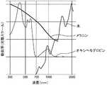
基本的に、光脱毛は、周囲の皮膚に影響を及ぼすことなく毛包に熱的に影響を及ぼすことにより毛髪の成長を低減又は阻害しようとするものである。毛包に熱的に影響を及ぼすには、毛包中の標的発色団によって光が吸収されなければならない。一般に、標的発色団はメラニンである(すなわち、一般的には茶色味/黒味がかったユーメラニンであるが、大部分が赤毛に存在する赤みがかったフェオメラニンも含む)。図1は、300nm〜2000nmの範囲の対数スケールで、メラニン、オキシヘモグロビン(血液)、及び水の相対光吸収率を示したものである(図1の吸収曲線は、Christine C.Dierickx,M.D.「Laser Hair Removal:Scientific Principle and Practical Aspects」,Lumenis,2002−www.lumenis.comより引用)。毛包のメラニン保持部において発生する熱は周囲組織に放散し、加熱時間及び温度が共に特定の閾値を上回れば最終的にタンパク質の凝固を生じるが、既に説明したように、加熱時間が長いほど凝固を生じる温度は低くなる。 Basically, photoepilation seeks to reduce or inhibit hair growth by thermally affecting hair follicles without affecting the surrounding skin. To have a thermal effect on the hair follicle, the light must be absorbed by the target chromophore in the hair follicle. In general, the target chromophore is melanin (ie, generally brown / blackish eumelanin, but also includes the reddish pheomelanin, which is predominantly present in redheads). FIG. 1 shows the relative light absorption rates of melanin, oxyhemoglobin (blood), and water on a logarithmic scale in the range of 300 nm to 2000 nm (the absorption curve in FIG. 1 is from Christine C. Dierickx, M. et al. D. "Laser Hair Removal: Scientific Principle and Practical Objects", Lumenis, 2002-www.lumenis.com). The heat generated in the melanin retention part of the hair follicle is dissipated to the surrounding tissue, and if both the heating time and temperature exceed a specific threshold, protein coagulation will eventually occur. The temperature at which solidification occurs becomes lower.
本開示は、大きな領域の皮膚処理装置(例えば少なくとも0.2cm2、詳細には約1〜4cm2、潜在的には最大10cm2の処理面積)及び非監視下での家庭での使用(すなわち、使用者が、怪我をするおそれなく、また医療従事者による専門的なサポートを行う必要なく、家庭で処理を行うことを可能とする)に基本的に関する。このような皮膚処理装置は、個々の毛包を特に個別に処理することなく、大きな皮膚領域を照射する。これは、毛包のない皮膚組織及び真皮組織内に存在する血管にも処理光パルスが照射されることを意味する。このような大きな領域の処理において皮膚組織及び血管に熱の影響が及ばないようにする(すなわち、皮膚組織及び血管への熱効果を家庭での使用で許容されるレベルに維持する)ために、最適な毛包処理は、メラニン吸収率が水による吸収及びオキシヘモグロビンによる吸収と比べて高い波長範囲で生じる。したがって、ユーメラニンを有する茶色味/黒味がかった毛髪(金髪、すなわち、かなり茶色味がかった毛髪を含む)では、最適な波長範囲は、水及びオキシヘモグロビンによる吸収率がメラニンに比べて低い630nm〜900nmの間である。フェオメラニンの吸収曲線はユーメラニンの曲線の下にあるため、発色団としてユーメラニンが基本的に存在せず、標的となるのがフェオメラニンだけである場合(すなわち、赤毛の場合)には光照射による脱毛は困難となる。図2は、ユーメラニン及びフェオメラニンについての(質量)吸光係数曲線を示したものである(T.Sarna,H.M.Swartz,The physical properties of melanins,in「The Pigmentary System」,ed.J.J.Nordlund et al.,Oxford University Press,1988より引用)。吸光係数は、ある物質が特定の波長の光をどの程度強く吸収するかを定義するパラメータである。図2は、630nm〜900nmの波長範囲の特定の放射フルエンスの処理光パルスは赤毛に対する効果が低く、そのため、タンパク質凝固を生じさせるのに充分に高い温度を毛包内に発生させることができないことを示している。したがって、赤毛は、オキシヘモグロビンが局所的吸収最小値を有する(図1を参照)約500nmの波長(例えば480nm〜510nmの波長範囲内)の光を照射することによって最も効果的に処理されるものと考えられる。The present disclosure describes large areas of skin treatment equipment (eg, treatment area of at least 0.2 cm2 , specifically about 1-4cm 2 , potentially up to 10 cm2 ) and home use (ie, unsupervised). (Allows the user to perform the treatment at home without the risk of injury and without the need for professional support by a healthcare professional). Such a skin treatment device irradiates a large skin area without treating the individual hair follicles specifically individually. This means that the treated light pulses are also applied to the blood vessels existing in the skin tissue without hair follicles and the dermis tissue. To prevent the effects of heat on the skin tissue and blood vessels in the treatment of such large areas (ie, to maintain the thermal effect on the skin tissue and blood vessels at levels acceptable for home use). Optimal hair follicle treatment occurs in a wavelength range where the melanin absorption rate is higher than that by water absorption and oxyhemoglobin absorption. Therefore, for brown / blackish hair with eumelanin (including blonde hair, ie, fairly brownish hair), the optimum wavelength range is 630 nm, which is less absorbed by water and oxyhemoglobin than melanin. It is between ~ 900 nm. Since the absorption curve of pheomelanin is below the curve of eumelanin, light is the case when eumelanin is basically absent as a chromophore and the target is only pheomelanin (ie, in the case of redheads). Hair removal by irradiation becomes difficult. FIG. 2 shows the (mass) extinction coefficient curves for eumelanin and pheomelanin (TM Sarna, HM Swartz, The physical policies of melanins, in “The Pigmentary System”, ed. J. . J. Nordlund et al., Oxford University Press, 1988). The extinction coefficient is a parameter that defines how strongly a substance absorbs light of a particular wavelength. FIG. 2 shows that the treated light pulse of a particular radiant fluence in the wavelength range of 630 nm to 900 nm has a low effect on redheads and therefore cannot generate enough temperature in the hair follicle to cause protein coagulation. Is shown. Therefore, redheads are most effectively treated by irradiating light with a wavelength of about 500 nm (eg, within the wavelength range of 480 nm to 510 nm) where oxyhemoglobin has a local minimum absorption (see FIG. 1). it is conceivable that.
光脱毛のための正しいパラメータの設定における主要な因子は、皮膚のメラニンによる光吸収及び皮膚のメラニン含有量に依存する皮膚に対する熱負荷の理解を得ることにある。皮膚のメラニン含量、すなわち皮膚の色は、FSTタイプI(淡い白色)からFSTタイプVI(最も深い色素沈着)までのスキンタイプを決定するフィッツパトリックスキンタイプ(Fitzpatrick skin type、FST)分類スケールに概ね関連している。肌色が濃いほど、皮膚のメラニン含有量が高く、皮膚のメラニン粒子による光吸収性が高いため、皮膚に対する熱負荷が高い。皮膚のメラニン粒子は1μm〜5μmの範囲の一般的なサイズを有しているのに対して、毛包は100μm〜300μmの範囲のサイズを有している。このようなメラニン担体のサイズの大きな差(毛包のメラニン保持部分対皮膚のメラニン顆粒)は、異なる熱放散挙動をもたらす。上述の皮膚のメラニン顆粒の熱弛緩時間が0.1ms未満であるのに対して、毛包の熱弛緩時間は約10msである。現在、毛包に熱による影響を及ぼすためには、一定の放射フルエンス(単位面積当たりの光エネルギー)を一定の時間枠内に照射する必要があると一般的に考えられている。これらのメラニン粒子から熱を放散させ、色素による光吸収による皮膚に対する熱負荷を低減するには、パルス長は皮膚のメラニン顆粒の熱弛緩時間を上回る値を有する必要があると考えられる。このため、パルス長は、詳細には熱緩和時間の10倍よりも長くすることができる(すなわち、少なくとも約1ms以上)。白色〜中間の肌色(FST I〜III)では、皮膚のメラニンの光吸収の作用のために熱の影響は限定的であり、最適なパルス長を決定するうえで重要な役割は果たさない。いずれにしても、1ms又は更には充分なフルエンスを下回るこのような短い光パルスは、今日のLEDダイでは、本明細書で述べられるような高い密度で実装した場合でも発生させることはできない。本開示によれば、少なくとも約10msのパルス長が検討される。必要とされる放射フルエンスが長すぎる処理光パルスとして与えられる場合、熱放散によって、毛包内で得られる温度は毛包内で効果的なタンパク質凝固が生じるには低すぎる値にまで低下してしまう。パルス長は、約300ms以下、詳細には約200ms以下でなくてはならないと考えられるが、この値は、基本的には毛包の熱弛緩時間によって決められ、典型的には熱弛緩時間の3〜10倍の範囲内になければならない(約10msの範囲でもよいが、大きな毛包ではより長くともよい)。少なくとも一時的な脱毛をもたらす効果(すなわち、一時的又は永久的な発毛の低減が生じるような少なくとも毛包における熱による変化)を得るために、この時間の間に供給される放射フルエンスは、1J/cm2〜8J/cm2とすべきである。ユーメラニンを保有する毛髪及び明るい肌色では、典型的には、4J/cm2〜8J/cm2が照射される。パルス長は一般的に10ms〜300msの範囲、詳細には20〜200msの範囲とすることができる。上記に述べたように、皮膚処理装置は、パルス長が80ms〜120msの範囲である処理光パルスを放射するように構成することができる。A key factor in setting the correct parameters for photoepilation is to gain an understanding of the light absorption by melanin in the skin and the heat load on the skin, which depends on the melanin content of the skin. Skin melanin content, or skin color, is roughly on the Fitzpatrick skin type (FST) classification scale, which determines skin types from FST type I (pale white) to FST type VI (deepest pigmentation). It is related. The darker the skin color, the higher the melanin content of the skin and the higher the light absorption by the melanin particles of the skin, so that the heat load on the skin is high. Skin melanin particles have a general size in the range of 1 μm to 5 μm, whereas hair follicles have a size in the range of 100 μm to 300 μm. Such large differences in melanin carrier size (melanin-retaining portion of hair follicles vs. melanin granules in the skin) result in different heat dissipation behaviors. The heat relaxation time of the melanin granules of the skin described above is less than 0.1 ms, whereas the heat relaxation time of the hair follicles is about 10 ms. At present, it is generally considered that it is necessary to irradiate a certain amount of radiant fluence (light energy per unit area) within a certain time frame in order to affect the hair follicles by heat. In order to dissipate heat from these melanin particles and reduce the heat load on the skin due to light absorption by the pigment, it is considered that the pulse length must have a value exceeding the heat relaxation time of the melanin granules in the skin. Therefore, the pulse length can be more than 10 times the heat relaxation time in detail (ie, at least about 1 ms or more). For white to intermediate flesh tones (FST I-III), the effect of heat is limited due to the action of light absorption of melanin in the skin and does not play an important role in determining the optimal pulse length. In any case, such short optical pulses below 1 ms or even sufficient fluence cannot be generated with today's LED dies, even when implemented at high densities as described herein. According to the present disclosure, pulse lengths of at least about 10 ms are considered. When the required radiant fluence is given as a processed light pulse that is too long, heat dissipation reduces the temperature obtained within the hair follicle to a value that is too low for effective protein coagulation within the hair follicle. It ends up. It is considered that the pulse length should be about 300 ms or less, more specifically about 200 ms or less, but this value is basically determined by the heat relaxation time of the hair follicle, and is typically of the heat relaxation time. It should be in the range of 3 to 10 times (may be in the range of about 10 ms, but may be longer for large hair follicles). Radiant fluence supplied during this time to obtain an effect that results in at least temporary hair loss (ie, at least a thermal change in the hair follicles that results in a temporary or permanent reduction in hair growth). It should be1J / cm 2 ~8J / cm 2 . The hair and bright skin color carrying eumelanin,typically, 4J / cm 2 ~8J / cm 2 is irradiated. The pulse length can generally be in the range of 10 ms to 300 ms, more specifically in the range of 20 to 200 ms. As described above, the skin treatment apparatus can be configured to emit treated light pulses with pulse lengths in the range of 80 ms to 120 ms.
考慮すべき別の因子として皮膚内部への光の浸透深さがある。光学的浸透深さ(光の強度が1/eにまで低下する距離)は、文献により異なるようである。例えば、1つの文献では、色白の白人の皮膚では、500nmの波長で0.230mmの浸透深さ〜1000nmの波長で約1.6mmの浸透深さとされている(R.Rox Anderson et al.,The Optics of Human Skin,The Journal of Investigative Dermatology,77:13〜19,1981)のに対して、別の文献では、500nmで約0.9mm〜1000nmで2.6mmの値とされている(Bashkatov,et.al.;Optical properties of human skin,subcutaneous and mucous tissues in the wavelength range from 400 to 2000nm;J.Phys.D:Appl.Phys.38(2005)2543〜2555)。これらの差によらず、浸透深さは一般的に波長1000nmから波長500nmにかけて大幅に減少する。毛包は、皮膚表面の約1〜3mm下に位置している。つまり、赤毛の処理に最適と考えられる波長は特に浅い浸透深さを有している。また、低波長光の浅い透過深さは更に短い波長の光、例えば、約300nmの紫外光の使用も排除し、紫外光は、紫外光による他のリスクを抜きにしても毛包に基本的に到達すらしない。皮膚組織では500nm付近の光の吸収が強いことから、3J/cm2〜約6J/cm2の範囲、詳細には3J/cm2〜約5J/cm2の範囲の放射フルエンスを照射するべきと考えられる。Another factor to consider is the depth of light penetration into the skin. The optical penetration depth (the distance at which the light intensity drops to 1 / e) appears to vary from literature to literature. For example, in one document, fair-skinned white skin has a penetration depth of 0.230 mm at a wavelength of 500 nm to a penetration depth of about 1.6 mm at a wavelength of 1000 nm (R. Rox Anderson et al.,. The Optics of Human Skin, The Journal of Investigative Dermatology, 77: 13-19, 1981), whereas in another document, the value is about 0.9 mm at 500 nm to 2.6 mm at 1000 nm (Bashkato). , Et. Al .; Optical products of human skin, subcutaneous and mucous tissues in the wavelength from range from 400 to 2000 nm; J. Phys. D: 25.Phys.D: Ap. Regardless of these differences, the penetration depth generally decreases significantly from a wavelength of 1000 nm to a wavelength of 500 nm. Hair follicles are located approximately 1-3 mm below the surface of the skin. That is, the wavelength considered to be optimal for the treatment of red hair has a particularly shallow penetration depth. The shallow transmission depth of low-wavelength light also eliminates the use of light of shorter wavelengths, such as ultraviolet light of about 300 nm, which is fundamental to hair follicles without the other risks of ultraviolet light. Does not even reach. Since the skin tissue strongly absorbs light around 500 nm, it should be irradiated with radiation fluence in the range of 3J / cm 2 to about 6 J / cm2 , specifically in the range of 3 J / cm2 to about 5 J / cm2. Conceivable.
上記に述べたように、本開示に基づく発光ユニットは、第1のLEDダイ1個当たり所定の放射フルエンスをそれぞれが有する複数の第1のLEDダイが充分に高い密度で実装された基板を有している(例えば、1平方cmあたり約8個〜約90個のLEDダイであるが、単位面積当たりのダイの数で表される実現可能な密度は当然ながらLEDダイのサイズにも依存する)。本開示に基づいて適当な第1のLEDダイの特定の例について以下に検討する。 As described above, the light emitting unit according to the present disclosure has a substrate on which a plurality of first LED dies, each having a predetermined radiation fluence per first LED die, are mounted at a sufficiently high density. (For example, about 8 to about 90 LED dies per square cm, but the feasible density expressed by the number of dies per unit area naturally depends on the size of the LED dies. ). Specific examples of suitable first LED dies based on the present disclosure are discussed below.
第1の例では、複数の第1のLEDダイが基板上に実装され、これら複数の第1のLEDダイのそれぞれのLEDダイは680nm〜780nmの波長範囲で発光するように構成される。この範囲で発光するLEDダイの1つの例として、Osram GmbH(Munich,Germany)より販売されるOSLON SSL(登録商標)150(GF CSHPM1.24−データシートバージョン1.0)に使用されているLEDダイがある。各LEDダイは、スペクトル帯域幅(FWHM)がΔλ=±30nmのピーク発光波長730nm(遠赤色)で発光する。このLEDダイは、350mAの順電流で201mW〜280mW(通常、231mW)の放射光束(放射出力とも呼ばれる)を有し、最大1000mAの順電流が指定されている(これにより、通常、660mWの放射光束を生じる)。 In the first example, a plurality of first LED dies are mounted on the substrate, and each LED die of the plurality of first LED dies is configured to emit light in a wavelength range of 680 nm to 780 nm. As an example of an LED die that emits light in this range, the LED used in the OSLON SSL® 150 (GF CSHPM1.24-datasheet version 1.0) sold by Osram GmbH (Munich, Germany). There is a die. Each LED die emits light at a peak emission wavelength of 730 nm (far red) with a spectral bandwidth (FWHM) of Δλ = ± 30 nm. This LED die has a luminous flux (also called radiated output) of 201 mW to 280 mW (usually 231 mW) with a forward current of 350 mA, and a forward current of up to 1000 mA is specified (thus usually radiating 660 mW). Produces a luminous flux).
Osram社から販売されているこれらのLEDダイ(約1mm×1mm=1mm2のダイサイズを有する)を約0.2mmの間隔で基板上に実装することができ、これにより、1cm×1cm=1cm2の基板面積上に8×8=64個のLEDダイを実装することができる。These LED dies sold by Osram (having a die size of about 1 mm x 1 mm = 1 mm2 ) can be mounted on the substrate at intervals of about 0.2 mm, thereby 1 cm x 1 cm = 1 cm. 8 × 8 = 64 LED dies can be mounted on the substrate area of2.
一般的に、大型のサイズのLEDダイは、0.5mm〜1.5mm×0.5mm〜1.5mm(すなわち、0.25mm2〜2.25mm2のサイズ)の範囲のサイズを有することができる。LEDダイは、ワイヤボンディング(詳細には金線ボンディング)によって基板に接続することができるが、高いパッケージングフォームファクター及び高い熱放散率を実現するためには、LEDダイは、フリップチップ技術によって基板に接続してもよい(そうすれば1平方cm当たり89個の1×1mm2のLEDダイの密度を実現することができる)。上記に述べたOsram社製のLEDダイ(1平方cm当たり64個のLEDダイの密度)を指定の順電流である1000mAで駆動して30ms〜200msのパルス長を有する処理光パルスを放射することにより、皮膚上の放射フルエンスは1.267J/cm2〜8.448J/cm2の範囲となる(全放射エネルギーが、実装された基板面積の大きさと同じ処理面積の大きさの皮膚領域に照射されるものと仮定する)。光パルスを放射する際にLEDダイが発生する余分な熱は、例えばヒートシンク、ヒートパイプ、又は能動的液体冷却システムなどの受動的又は能動的な冷却装置によって基板から放散させることができる。受動的冷却装置(例えばヒートシンク)は、(冷却された)空気流を与えることにより支持することができる。LEDダイの効率は30%程度であることが多く、8J/cm2の放射フルエンスを発生する処理光パルスは、約18.7J/cm2の余分な熱を放散せざるを得ないことを意味する。約1秒以上の所定の冷却時間を必要とするフラッシュランプに対して、LEDダイはより高い周波数でパルスさせることができるため、LEDダイによって大きな皮膚面積でより速やかな全体の処理時間を実現することができる。Generally, LED die of a large size, have a size in the range of 0.5 mm to 1.5 mm × 0.5 mm to 1.5 mm(i.e., the size of 0.25mm2 ~2.25mm 2) can. The LED die can be connected to the substrate by wire bonding (specifically, gold wire bonding), but in order to achieve a high packaging foam factor and high heat dissipation rate, the LED die is a substrate by flip chip technology. (Then a density of 89 1 × 1 mm2 LED dies per square cm can be achieved). The above-mentioned Osram LED die (density of 64 LED dies per square cm) is driven at 1000 mA, which is a specified forward current, to emit a processed light pulse having a pulse length of 30 ms to 200 ms. As a result, the radiant fluence on the skin is inthe range of 1.267 J / cm 2 to 8.448 J / cm2 (total radiant energy irradiates the skin area with the same treated area as the mounted substrate area). It is assumed that it will be done). The extra heat generated by the LED die when emitting light pulses can be dissipated from the substrate by a passive or active cooling device such as a heat sink, heat pipe, or active liquid cooling system. Passive cooling devices (eg, heat sinks) can be supported by providing a (cooled) air stream. The efficiency of LED dies is often around 30%, which means that the processed light pulse that produces8 J / cm 2 radiant fluence has to dissipate extra heat ofabout 18.7 J / cm 2. do. For flashlamps that require a predetermined cooling time of about 1 second or longer, the LED die can be pulsed at a higher frequency, so the LED die provides a faster overall processing time over a larger skin area. be able to.
上記に述べた第1の例では、8個×8個のLEDダイのアレイのうちの4個のLEDダイを、第1の波長とは異なる第2の波長(例えば、第2の波長は400nm〜700nmの可視範囲にあってよい)で発光する異なるLEDダイに置き換えることができるが、その場合も皮膚上のフルエンスは30ms〜200msのパルス長に対して基本的に1J/cm2〜8J/cm2の範囲にわたる。In the first example described above, four LED dies out of an array of 8 x 8 LED dies have a second wavelength different from the first wavelength (eg, the second wavelength is 400 nm). It can be replaced with a different LED die that emits light in the visible range of ~ 700 nm), but even then the fluence on the skin is basically 1 J / cm2 ~ 8 J / for a pulse length of 30 ms ~ 200 ms. Over the range of cm2.
第2の例では、第1のLEDダイは、Osram GmbH(Munich,Germany)より販売されるOSLON Blackシリーズ(850nm)のものを使用することができる。データシート(2014−01−09からのバージョン1.1)によれば、各LEDダイ(1×1mm2のサイズ)は、スペクトル帯域幅(FWHM)がΔλ=±30nmのピーク発光波長860nm(中心波長:850nm)で発光する。全発光光束は、1000mAの順電流で1030mWとして与えられる。1cm2の基板面積上に予め実装された5個のこのようなLEDダイは、1cm2の皮膚処理面積上で200msのパルス長当たり約1J/cm2の放射フルエンスを与える(LEDダイの全放射光束が皮膚処理面積上に照射されると仮定する)。In the second example, the first LED die can be an OSLON Black series (850 nm) sold by Osram GmbH (Munich, Germany). According to the data sheet (version 1.1 from 2014-01-09), each LED die (1 x 1 mm2 size) has a peak emission wavelength of 860 nm (center) with a spectral bandwidth (FWHM) of Δλ = ± 30 nm. It emits light at a wavelength (wavelength: 850 nm). The total luminous flux is given as 1030 mW with a forward current of 1000 mA. Five such LED dies pre-mounted on a 1 cm2substrate area provide approximately 1 J / cm 2 radiant fluence per 200 ms pulse length ona 1 cm 2 skin treatment area (total radiation of the LED dies). It is assumed that a luminous flux is applied over the treated area of the skin).
第3の例では、8個×8個のLEDダイのアレイが1cm2の基板面積上にやはり実装される。第1の部分複数の44個の第1のLEDダイ(730nmの第1の波長で発光するOSLON SSL(登録商標)150)が、第2の部分複数の20個の第2のLEDダイ(850nmの第2の波長で発光するOSLON Blackシリーズ)と本質的に混在している。第1のLEDダイのみがオンされて200msの処理光パルスを発光する場合に、5.8J/cm2のフルエンスが得られる。第2のLEDダイ(850nm)のみがオンされて200msの処理光パルスを発光する場合に、4J/cm2以上のフルエンスが得られる。共にオンされる場合、おおよそ10J/cm2のフルエンスが200msの処理光パルスで得られる(又は100msの処理光パルスでおおよそ5J/cm2のフルエンス)。In the third example, an array of 8 x 8 LED dies is also mounted on a1 cm 2 substrate area. The 44 first LED dies (OSLON SSL® 150 that emits light at the first wavelength of 730 nm) of the first part are the 20 second LED dies (850 nm) of the second part. It is essentially mixed with the OSLON Black series) that emits light at the second wavelength of. When only the first LED die is turned on and emits a processed light pulse of 200 ms, a fluence of5.8 J / cm 2 is obtained. When only the second LED die (850 nm) is turned on and emits a processed light pulse of 200 ms,a fluence of 4 J / cm 2 or more can be obtained. When both are turned on, approximately 10 J / cm2 fluence is obtained with a 200 ms processed light pulse (or approximately 5 J / cm2 fluence with a 100 ms processed light pulse).
更なる一例では、502nmのピーク発光波長(505nmの通常の主波長)で発光するOsram GmbH(Munich,Germany)より販売されるGolden DRAGON Plus LV W5AM LEDダイが使用されている。データシート(バージョン1.1)によれば、このLEDダイは、順電流350mAで67lmの光束を有する。67lmは、505nmの波長で約240mWの放射光束に変換される(線形外挿を用いた場合、1000mAの順電流で約684mW)。主波長505nmのLEDダイは主波長の周囲のスペクトル帯域で発光することと、ルーメンのワットへの変換は波長に強く依存していることから、この値はあくまで推定値にすぎない。200msの処理光パルスで約3J/cm2の放射フルエンスを得るには1平方cm当たり約21個のこのような505nmのLEDダイが必要とされる。したがって、1平方cm当たり約44個の505nmのLEDダイは100msのパルスで3J/cm2の放射フルエンスを与え、約88個の505nmのLEDダイは100msのパルスで約6J/cm2の放射フルエンスを与える。約88個の505nmのLEDダイは、50msのパルスで約3J/cm2の放射フルエンスを与えることができる。脱毛装置は、更に赤毛処理性能を与えるために複数のこのようなLEDダイを更に有することができる。少なくとも1つの第2のLEDダイは、Golden DRAGON Plus LV W5AM LEDダイとすることができる。これらのLEDダイは処理光を放射するための第1のLEDダイとして使用することができる一方で、選択された第1のLEDダイの活性領域を視覚的に示すための第2のLEDダイとして使用することもできる。したがって、特定の実施形態では、第1のLEDダイと第2のLEDダイとは同じ種類のものであり(例えばこの段落で述べた種類のもの)、第2のLEDダイは、処理パルスの持続時間外では、選択された活性領域を視覚的に示すために使用され、処理パルスの持続時間の間では処理光を発光するために第1のLEDダイとともに使用される。As a further example, a Golden DRAGON Plus LV W5AM LED die sold by Osram GmbH (Munich, Germany), which emits light at a peak emission wavelength of 502 nm (a normal main wavelength of 505 nm), is used. According to the data sheet (version 1.1), this LED die has a luminous flux of 67 lm at a forward current of 350 mA. 67 lm is converted to a luminous flux of about 240 mW at a wavelength of 505 nm (about 684 mW at a forward current of 1000 mA when using linear extrapolation). This value is only an estimate because an LED die with a main wavelength of 505 nm emits light in the spectral band around the main wavelength and the conversion of lumens to watts is strongly wavelength dependent. Approximately 21 such 505 nm LED dies per square cm are required to obtain approximately 3 J / cm2 radiant fluence with a 200 ms processed light pulse. Therefore, about 44 505 nm LED dies per square cmgive 3 J /
本明細書で検討される値は、LEDダイの放射光束がLEDダイの温度、順電流及び他の因子に依存することから、比較的大まかな参考値である点を理解されたい。 It should be understood that the values considered herein are relatively rough reference values as the luminous flux of the LED die depends on the temperature, forward current and other factors of the LED die.
表1は、本明細書の発明者らが、所与の毛色及びFSTスキンタイプに対する最適な処理パラメータを表しているものと考えるところの波長、パルス長、及びフルエンス値をまとめたものである。波長は、それぞれの場合で波長範囲の代表的なものであると理解され、その範囲は、所与の1つの波長の値の周囲の±50nm(場合により±30nm)の範囲をカバーするものとする。注意すべき点として、特定の実施形態では、皮膚処理装置は、制御ユニットが表1に従って(赤毛の場合を除き)第1のLEDダイを作動することができるように、730nm付近のピーク発光波長で発光するように構成された第1の部分複数の第1のLEDダイと、850nm付近のピーク発光波長で発光するように構成された第2の部分複数の第1のLEDダイとを有する。更に、制御ユニットが表1に従って第1のLEDダイを作動することができるように、500nm付近のピーク発光波長で発光するように構成された第3の部分複数の第1のLEDダイが存在してもよい。 Table 1 summarizes the wavelengths, pulse lengths, and fluence values that the inventors of the present specification consider to represent optimal processing parameters for a given coat color and FST skin type. Wavelengths are understood to be representative of the wavelength range in each case, which covers a range of ± 50 nm (possibly ± 30 nm) around the value of one given wavelength. do. It should be noted that in certain embodiments, the skin treatment apparatus has a peak emission wavelength near 730 nm so that the control unit can operate the first LED die according to Table 1 (except for redheads). It has a first partial LED die configured to emit light in, and a second partial plurality of first LED dies configured to emit light at a peak emission wavelength near 850 nm. Further, there is a third partial first LED die configured to emit light at a peak emission wavelength near 500 nm so that the control unit can operate the first LED die according to Table 1. You may.
図3は、本発明に基づく発光ユニット10の例示的な一実施形態の概略図である。発光ユニット10は、64個の複数のLEDダイが実装された基板100を有している。LEDダイは、行A〜Hと列1〜8とからなる8×8の規則的な矩形のパターンに配列されており、各LEDダイを行列内のそれらの位置によって識別することができる。例として3個のLEDダイ101A1、101A8、及び101E5が示されており、行列の配列内のLEDダイは、それぞれの参照数字に添え字として付与された行と列とによって識別することができることが理解される。FIG. 3 is a schematic view of an exemplary embodiment of the
8×8の正方形のLEDダイの行列はあくまで一例にすぎず、LEDダイは、2×2、2×4、3×6、5×5、10×14、4×15(図4Bを参照)といった行列などの正方形又は長方形の行列、あるいはそれほど組織化されていない、よりランダムなパターンとして、任意の実用的な形で基板上に配列することができる点を理解されたい。LEDダイは、正方形又は長方形の行列として配列する代わりに、正方形又は長方形の領域よりもむしろ円形の領域に似た規則的なパターンで配列することもできる。実装される基板領域の他の任意の形状も選択することができる(例えば、三角形、台形、任意形状)。図4A、図5及び図6の例では、説明を簡単にする目的で同じ8×8の行列を用いるが、これらの図に関して説明される概念及び発想は、上述の、基板に実装されるLEDダイの他の規則的又は不規則的なパターンにも適用可能であることは言うまでもない。図4Bは、4×15の行列を用いた一実施形態を示している。 The 8x8 square LED die matrix is just an example, and the LED dies are 2x2, 2x4, 3x6, 5x5, 10x14, 4x15 (see Figure 4B). It should be understood that a square or rectangular matrix, such as a matrix such as, or a less organized, less random pattern, can be arranged on the substrate in any practical form. Instead of arranging the LED dies as a square or rectangular matrix, they can also be arranged in a regular pattern that resembles a circular area rather than a square or rectangular area. Any other shape of the board area to be mounted can also be selected (eg, triangle, trapezoid, arbitrary shape). In the examples of FIGS. 4A, 5 and 6, the same 8x8 matrix is used for the sake of brevity, but the concepts and ideas described for these figures are the LEDs mounted on the substrate described above. It goes without saying that it is also applicable to other regular or irregular patterns of dies. FIG. 4B shows an embodiment using a 4 × 15 matrix.
制御ユニット20は、LEDダイ101の各々に選択的に電圧及び電流を供給するためにLEDダイの行列に接続されたリード線を有している。上記で述べたように、8×8の行列は、各列が同時に制御されるように直列に接続された8列のLEDダイを有している。一般的に、制御ユニット20は、すべてのLEDダイを同時にオン及びオフするように構成することができるが、制御ユニット20は基板上に実装されたLEDダイのそれぞれを個別にオン又はオフするように構成することもできる。一般的に、制御ユニットは、複数のLEDダイに任意の適当な方法で接続することができる。 The
制御ユニット20には、例えば肌色(色素沈着レベル)などの皮膚特定を測定するためのセンサ30が接続されている。センサは、皮膚を照射する光源を有してもよく、センサはセンサに後方散乱される(例えば光ダイオードにより実現される)光の量から肌色などの皮膚特性を決定するように構成することができる。制御ユニット20は、詳細には、更に例えば光強度及び/又はパルス長などの測定された肌色に基づいて少なくとも1つの処理パラメータを制御するように構成することができる。センサ30は、任意選択的な要素として理解されるべきである。 A
この場合、制御ユニット20はユーザインターフェース40、50、60、70にも接続されており、ユーザが発光ユニット10の各側面を制御することを可能とする。ここで、ユーザインターフェースは、4つの入力素子40、50、60、及び70を有している。第1の入力素子40をオン/オフスイッチとして構成することができる。第2の入力素子50は、処理のタイプを選択するスイッチとして構成することができ、例えば第2の入力素子50は、ユーザが脱毛機能と皮膚再生機能との間で切り替えを行うことを可能とするものとすることができる。更に、制御ユニット20は選択された処理のタイプに基づいて少なくとも1つの処理パラメータを制御するように構成することができ、例えば、LEDダイによって放射される放射光束を、脱毛機能におけるよりも、皮膚再生機能でより低くすることができる。第3の入力素子60は、ユーザが髪色を入力できるように構成することができる。更に、制御ユニット20は、髪色に応じて少なくとも1つの処理パラメータを制御するように構成することができる。第4の入力要素70は、ユーザが、皮膚に照射される最大放射フルエンスの値を設定できるように構成することができる(例えば1J/cm2から8J/cm2の範囲の値)。ここで、制御ユニット20は、選択された最大放射フルエンスを上回らない放射フルエンスの光パルスのみを照射するように構成することができる。これに加えるか又はこれに代えて、入力素子のうちの1つは、ユーザが、実装された第1のLEDダイの第1の活性領域から第2の活性領域に切り替えることができるように構成することができる(以下の図4A及び図4Bに関する説明を参照)。入力素子40、50、60、又は70のそれぞれは、入力ノブ又はスライダー、あるいはタッチ感受性ボード上のタッチ感受性スイッチとして構成することができる。制御ユニット20に有線接続されているものに対して、ユーザインターフェースは、制御ユニット20と無線で接続された別の装置上で実現することができる。図3に示されるような4つの入力素子の代わりに、ユーザインターフェースは、1個、2個、3個、5個、6個、又は任意の数の入力素子を有することができる。特定の実施形態では、発光ユニット10はいずれのユーザインターフェースも含まず、自動化された形で動作するように構成することができる。上記に述べた機能の他の又は更なる機能をユーザインターフェースを介して実現することができる。In this case, the
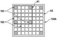
図4Aは、基板100A上に実装された複数の第1及び第2のLEDダイ102及び103の構成の一例である。複数の第1のLEDダイ102は57個の要素を有している。複数の第2のLEDダイ103は7個の要素を有している。複数の第2のLEDダイ103の7個の要素は、それらの行列での位置によって103A1、103E1、103H1、103A5、103E5、103A8、及び103H8として識別される。複数の第1のLEDダイ102は、ヒトの目に基本的に見えない遠赤色又は赤外(IR)波長(第1の波長)で発光するように構成することができる。このような第1のLEDダイを用いて皮膚表面に処理光パルスを照射することができる。第2のLEDダイ103は、400nm〜700nmの可視波長範囲(第1の波長とは異なる第2の波長)で発光するように構成することができ、詳細には、第2のLEDダイは、一時脱毛を行うのに充分な強度レベルで発光させるのには適さない低放射光束のLEDダイとして構成することができる(例えば、第2のLEDダイは、約2Vの供給電圧において100mA未満、詳細には、約50mA又は20mAの指定された順電流を有することができる)。第2のLEDダイを使用して処理光パルスの持続時間外の時間において、選択された第1のLEDダイの活性領域を示す。これにより、オンされた第2のLEDダイ103A1、103E1、103A5、及び103E5は、これら4個の第2のLEDダイの間に配置された第1のLEDダイのみが皮膚に処理光を照射するために使用されることを示す(この第1の選択可能な活性領域A1は破線により示されている)のに対して、オンされた第2のLEDダイ103A1、103H1、103A8、及び103H8は、複数の第1のLEDダイの全体が使用されることを示す(この第2の選択可能な活性領域A2は一点鎖線により示されている)。より小さい第1の選択可能な活性領域A1が顔面の皮膚の処理に有用である(より小さい選択可能な活性領域A1は小さい顔の領域をより正確に標的化することができる)のに対して、より大きな選択可能な活性領域A2は身体の皮膚の処理に有用である(より速やかな処理)。既に上記に述べたように、ユーザが選択可能な活性領域の1つを選択することができるように入力素子を設けることができる。この例では、第1の選択可能な活性領域A1内にある第1のLEDダイが第1の選択可能な活性領域に指定され、第2の選択可能な活性領域A2内にある第1のLEDダイ(複数の第1のLEDダイのすべてを意味する)が第2の選択可能な活性領域A2に指定されている。第2のLEDダイ103A1、103E1、103A5、及び103E5は第1の選択可能な活性領域A1に指定され、第2のLEDダイ103A1、103H1、103A8、及び103H8は第2の選択可能な活性領域A2に指定されている。この場合、各第2のLEDダイは矩形の選択可能な活性領域の隅に配置されている。第2のLEDダイ103A1は、選択可能な活性領域の共通の隅に配置されていることから、両方の選択可能な活性領域に指定されている。FIG. 4A is an example of the configuration of the plurality of first and second LED dies 102 and 103 mounted on the
LEDダイのパターンに応じて、少なくとも2個の第2のLEDダイを用いて選択された活性領域を示すことができる(例えば、第2のLEDダイを正方形又は長方形の配列の互いに反対側の隅に配置することができる)。特定の実施形態では、第1のLEDダイの活性領域を第2のLEDダイによって取り囲むことで活性領域を示すことができる。図4Aに示される構成の代わりに、隅に配置された各第2のLEDダイを第1のLEDダイに置き換えることができ、それぞれの第2のLEDダイを図に示される8×8の行列の外側で、各隅点の近くに配置することができる。更に、例えば、行列を拡大することにより、第2の(より大きな)選択可能な活性領域A2を示すための第2のLEDダイを位置(A,0)、(A,9)、(H,0)、及び(H,9)に配置することができる。 Depending on the pattern of the LED dies, at least two second LED dies can be used to indicate the selected active region (eg, the second LED dies in a square or rectangular array of opposite corners. Can be placed in). In certain embodiments, the active region can be indicated by surrounding the active region of the first LED die with a second LED die. Instead of the configuration shown in FIG. 4A, each second LED die located in the corner can be replaced with a first LED die, each second LED die being an 8x8 matrix shown in the figure. It can be placed on the outside of the LED, near each corner point. Further, for example, by expanding the matrix, a second LED die is positioned to indicate a second (larger) selectable active region A2 (A, 0), (A, 9), (H, It can be arranged at 0) and (H, 9).
上記に述べたように、また、一般的な説明として、第2のLEDダイは、選択された活性領域を処理パルスの持続時間外で視覚的に示すために使用することができる。例えば、ユーザは皮膚処理装置をオンすることができる。すると、第2のLEDダイは作動されないか(そして装置は選択を待つ)、又は、装置がオフされる前に選択された活性領域が示されるか、又は、選択可能な活性領域の1つを基準選択として用い、この基準の選択可能な活性領域に指定されたそれぞれの第2のLEDダイが作動されて、選択された活性領域を視覚的に示す。選択された活性領域の視覚的な表示をユーザがオン及びオフすることを可能とする制御要素が設けられてもよい。 As mentioned above, and as a general description, the second LED die can be used to visually indicate the selected active region outside the duration of the processing pulse. For example, the user can turn on the skin treatment device. The second LED die is then not activated (and the device waits for selection), or the selected active region is shown before the device is turned off, or one of the selectable active regions. Used as a reference selection, each second LED die designated for a selectable active region of this criterion is activated to visually indicate the selected active region. Control elements may be provided that allow the user to turn on and off the visual display of the selected active region.
一般的に、特定の実施形態では、少なくとも3個の第2のLEDダイのうちの1個のみが、処理光パルスと同時に可視光パルスを発生するために使用される。第2のLEDダイは、詳細には、低い放射光束(例えば、通常、約20mA〜50mAの順電流で100mW未満)で発光するように構成することができる。第2のLEDダイは、例えば700nmよりも大きい遠赤色又はIR波長範囲にあるためにヒトの目には見えない場合がある処理光パルスの放射と同時に可視光パルスを放射するように制御される。 Generally, in certain embodiments, only one of at least one of the three second LED dies is used to generate a visible light pulse at the same time as the processed light pulse. The second LED die can be specifically configured to emit light with a low luminous flux (eg, typically less than 100 mW with a forward current of about 20 mA to 50 mA). The second LED die is controlled to emit visible light pulses at the same time as it emits processed light pulses that may be invisible to the human eye, eg, in the far red or IR wavelength range greater than 700 nm. ..
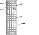
図4Bは、図4Aに示される実施形態に似た基板100AA上に実装された4×15のLEDダイの行列の例示的な一実施形態を示しており、処理光パルスを放射するように構成された54個の複数の第1のLEDダイ102Aに加えて、6個の複数の第2のLEDダイ103Aが、第1の選択可能な活性領域A3又はより大きい第2の選択可能な活性領域A4を示すために可視波長範囲で発光するように配列されている。このような長方形のLEDダイのアレイは、図4Aに示されるようなLEDダイアレイを使用することができるように1つの皮膚処理領域から別の皮膚処理領域へと順次動かされる代わりに、皮膚に沿って連続的に動かされる皮膚処理装置に特に使用される。このような滑らかな動きは、特に長方形のLEDダイアレイの長軸に垂直な方向に特に生じ得る。特定の実施形態では、滑らかに使用される皮膚処理装置は、皮膚に沿って装置が動かされる速度を測定するための速度センサを有することができる。したがって、この皮膚処理装置を、測定された滑らかな運動の速度に応じて連続した処理光パルス間の時間を制御するように構成することで、処理光パルスが皮膚に途切れることなく(すなわち、隙間や重なり合いを基本的に生じることなく)照射されるようにすることができる。長方形の形状のため、より小さい活性領域A3がLED行列の幅全体をカバーしており、これにより、より小さい活性領域A3を処理領域上に正確に位置決めする助けとなる。 FIG. 4B shows an exemplary embodiment of a matrix of 4 × 15 LED dies mounted on a substrate 100AA similar to the embodiment shown in FIG. 4A, configured to radiate processed light pulses. In addition to the 54 first selectable LED dies 102A, the six second selectable LED dies 103A have a first selectable active region A3 or a larger second selectable active region. They are arranged to emit light in the visible wavelength range to indicate A4. Such a rectangular array of LED dies is along the skin instead of being moved sequentially from one skin treatment area to another so that the LED die array as shown in FIG. 4A can be used. Especially used for skin treatment devices that are continuously moved. Such smooth movement can occur especially in the direction perpendicular to the long axis of the rectangular LED die array. In certain embodiments, the smoothly used skin treatment device can have a speed sensor for measuring the speed at which the device is moved along the skin. Therefore, by configuring this skin treatment device to control the time between continuous treatment light pulses according to the measured rate of smooth movement, the treatment light pulses are uninterrupted in the skin (ie, crevices). It can be made to be irradiated (without essentially causing overlap). Due to the rectangular shape, the smaller active region A3 covers the entire width of the LED matrix, which helps to accurately position the smaller active region A3 on the processing region.
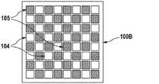
図5は、8×8のLEDダイの行列の例示的な一実施形態を示しており、32個の第1の部分複数の第1のLEDダイ104と、32個の第2の部分複数の第1のLEDダイ105とが基板100B上に市松模様のパターンで実装されている(例えば、実装された基板領域にわたってLEDダイが基本的に均一に分布することになる)。詳細には、実装されたLEDダイのアレイが操作時に処理される皮膚に近接して配置される場合、第1の部分複数の第1のLEDダイ、又は第2の部分複数の第1のダイのどちらかのみを作動させることにより、実質的に均一な照明を実現することができる。第1の部分複数の第1のLEDダイ104を第1の波長で発光するように構成することができ(詳細には、少なくとも一時的な脱毛に充分な強度レベルで)、第2の部分複数の第1のLEDダイを第1の波長とは異なる第2の波長で発光するように構成することができる。第2の部分複数の第1のLEDダイは、単独でも少なくとも一時的な脱毛に充分な放射光束で発光することができるが、第2のLEDダイは皮膚再生又は他の皮膚処理に充分な放射光束で発光することもできる。この実施形態には示されていないが、第2のLEDダイは、図4Aを参照して説明されたように、選択可能な活性領域の隅の近くに配置されるものとして理解される。市松模様のパターンで配列される代わりに、第1及び第2の部分複数の第1のLEDダイを他の任意のパターンで配置することもでき、第2の部分複数の第1のLEDダイよりも多いか又は少ない第1の部分複数の第1のLEDダイを設けることができる(例えば、2個、7個、10個、16個、20個、40個など)。上記に述べたように、ここで示した8×8の行列はあくまで例示の目的のものにすぎず、少なくとも第1のLEDダイが通常の動作時に皮膚に10ms〜300msのパルス長を有するパルスで少なくとも1J/cm2の放射フルエンスを発生させるように配列されている限り(すなわち、第1のLEDダイが少なくとも3.333W/cm2で発光する(第1のLEDダイの活性アレイの領域が、同じサイズの皮膚領域を放射すると仮定する))、あらゆる任意の数の第1のLEDダイを、あらゆる任意のパターンで配列することができる。FIG. 5 shows an exemplary embodiment of a matrix of 8x8 LED dies, with 32 first portion plurality of first LED dies 104 and 32 second portion plurality. The first LED die 105 is mounted on the
図6は、基板100C上に実装された8×8のLEDダイの行列の別の例示的な実施形態を示しており、4種類の異なる部分複数の第1のLEDダイが基板100C上に実装されている。20個の第1の部分複数の第1のLEDダイ106、21個の第2の部分複数の第1のLEDダイ107、及び21個の第3の複数の第1のLEDダイ108が交互に基板上に実装されている。LEDダイアレイの中心には、照明目的(すなわち処理光パルスの放射と同時に可視光パルスを放射する目的)に適した放射光束で可視波長範囲で発光するように構成することができる2個の第4の部分複数の第1のLEDダイ109が実装されている。特定の実施形態では、第1の部分複数の第1のLEDダイ106は第1の波長(例えば850nm)で発光するように構成することができ、第2の部分複数の第1のLEDダイ107は第1の波長とは異なる第2の波長(例えば730nm)で発光するように構成することができ、第3の複数の第1のLEDダイ108は第1及び第2の波長とは異なる第3の波長(例えば505nm)で発光するように構成することができる。 FIG. 6 shows another exemplary embodiment of a matrix of 8x8 LED dies mounted on the
図7Aは、本発明に基づく皮膚処理装置80の図を示す。皮膚処理装置80には、上記の段落で述べた発光ユニットが使用されている。皮膚処理装置80は、処理光パルスを放射するためのヘッド部81と、ユーザが手で皮膚処理装置80を保持するためのハンドル部82とを有している。皮膚処理装置80を少なくともオン/オフするための制御素子85がハンドル部82に配置されている。図7B〜図7Dは、ヘッド部81A、81B、81Cの異なる実施形態の正面図を示しており、各実施形態は、少なくとも1つの皮膚特性を測定するための1乃至複数のセンサ95A、95B、95Cの位置においてのみ本質的に異なっている。ヘッド部81A、81B、81Cはそれぞれ、操作時に処理光パルスがそこから放射される各出口開口部90A、90B、又は90Cを有している。複数のLEDダイが実装された基板は、各出口開口部90A、90B、又は90Cのすぐ後方に配置してもよく、又は基板は、ヘッド部81A、81B、81Cの内部に各出口開口部90A、90B、又は90Cから約10mm又は10mm未満の特定の距離に配置してもよい。LEDダイが放射する光を基本的に透過する材料で形成された出口窓91A、91B、91Cが各出口開口部90A、90B、又は90Cを覆っている。出口開口部90A、90B、又は90Cは、0.2mm2〜10cm2の範囲、詳細には1cm2〜4cm2の範囲のサイズを有することができる。したがって、基板の実装領域は、各出口開口部90A、90B、又は90Cと同じサイズ及び形状を有することができる。特定の実施形態では、出口窓91A、91B、91Cは設けられない。図7Bの実施形態では、皮膚処理装置は、少なくとも1つの皮膚特性を測定するための2個のセンサ95Aを有しており、これら2個のセンサ95Aは出口開口部90Aの互いに反対側の2辺に配置されている。図7C及び7Dに示される実施形態では、少なくとも1つの皮膚特性を測定するための1個のみのセンサ95B及び95Cがそれぞれ、ヘッド部81B及び81C上にそれぞれ配置されている。図7Cでは、センサ95Bは出口開口部90Bの下に配置されているため、センサ95Bは通常の運動方向(図7Cに基づく装置は滑らかな運動モードで使用することができる)に対して出口開口部90Bの手前に配置されている。図7Dでは、センサ95Cは出口開口部90Cの中心領域に配置されている。この場合、出口開口部90Cに近接して配置される基板は対応する切欠き部を有することができ、それによりセンサを切欠き部内に配置してこの切欠き部を通じて操作することができる。1乃至複数のセンサ95A、95B、95Cが皮膚との接触を検出するようにしてもよく、これにより、皮膚との接触が検出された場合に処理光パルスの放射のみをトリガするように発光ユニットの制御ユニットを構成することができる。FIG. 7A shows a diagram of a
図8は、動作時にLEDダイが発生する余分な熱を伝達除去するためのヒートシンク210上に実装された基板実装LEDダイアレイ200の図である。ヒートシンクの近くにファンを配置することによってヒートシンクからの熱の放散を助けることができる。 FIG. 8 is a diagram of a substrate-mounted LED die
図9A及び図9Bは、基板実装LEDダイアレイ300の斜視図及び断面図を示しており、ケーシング310が実装領域320の周囲に実装されている。ケーシング310は、第1のLEDダイが放射する光に対して高い反射性を有する内壁表面311を有している。内壁表面311は、研磨された金属又は拡散反射性のプラスチック若しくはセラミック材料で形成され得る反射性コーティングを有することができる。これにより、ケーシング310は、第1のLEDダイが放射する光を第1のLEDダイの面から皮膚処理装置の出口開口部まで基本的に損失がないように案内する機能を有し、第1のLEDダイの面における放射光束は出口開口部が皮膚に置かれる際に処理領域上で測定される放射光束と基本的に同じとなる。 9A and 9B show a perspective view and a cross-sectional view of the board-mounted LED die
本明細書に開示した寸法及び値は、列挙された正確な数値に厳密に限定されるものと理解されるべきではない。むしろ、別段の指定がない限り、かかる寸法はそれぞれ、列挙された値及びその値の周辺の機能的に等価な範囲の両方を意味するものとする。例えば、「40mm」として開示される寸法は、「約40mm」を意味するものとする。 The dimensions and values disclosed herein should not be understood to be strictly limited to the exact numbers listed. Rather, unless otherwise specified, such dimensions shall mean both the listed values and the functionally equivalent range around those values, respectively. For example, the dimension disclosed as "40 mm" shall mean "about 40 mm".
Claims (8)
Translated fromJapanese基板と、該基板上の少なくとも0.2cm2の領域に実装された複数の第1のLEDダイと、を有する発光ユニットを備え、
前記脱毛装置が、前記第1のLEDダイを作動して、10ms〜300msの範囲のパルス長を有する処理光パルスを放射するように構成され、前記第1のLEDダイが、前記処理光パルスの照射によってユーザの皮膚上で少なくとも1J/cm2の放射フルエンスが得られるような放射光束を有し、
前記発光ユニットが、少なくとも2つの選択可能な第1のLEDダイの活性領域を有し、前記選択可能な活性領域が異なるサイズを有し、少なくとも3個の第2のLEDダイが基板上の前記選択可能な活性領域のそれぞれを視覚的に示すのに適した位置に実装され、
前記第2のLEDダイが、前記選択可能な第1のLEDダイの活性領域の隅又は端点に配置されるか、又は前記選択可能な第1のLEDダイの活性領域の前記隅又は端点に近接して実装され、
前記第1及び第2のLEDダイを制御するための制御ユニットを更に備えている、脱毛装置。It ’s a hair removal device,
A light emitting unit comprising a substrate and a plurality of first LED dies mounted in an area of at least 0.2 cm2 on the substrate.
The hair removal device is configured to operate the first LED die to radiate a processed light pulse having a pulse length in the range of 10 ms to 300 ms, the first LED die of the processed light pulse. It has a luminous flux such that irradiation gives a radiation fluence of at least 1 J / cm2 on the user's skin.
The light emitting unit has at least two selectable first LED die active regions, the selectable active regions have different sizes, and at least three second LED dies are said on the substrate. Implemented in a suitable position to visually indicate each of the selectable active regions,
The second LED die is located at a corner or endpoint of the active region of the selectable first LED die, or is close to the corner or endpoint of the active region of the selectable first LED die. Implemented,
A hair removal devicefurther comprising a control unit for controlling the first and second LED dies.
Applications Claiming Priority (5)
| Application Number | Priority Date | Filing Date | Title |
|---|---|---|---|
| EP16153813.7AEP3202351B1 (en) | 2016-02-02 | 2016-02-02 | Skin treatment device |
| EP16153813.7 | 2016-02-02 | ||
| EP17152188.3AEP3202361B1 (en) | 2016-02-02 | 2017-01-19 | Skin treatment device |
| EP17152188.3 | 2017-01-19 | ||
| PCT/IB2017/050482WO2017134552A1 (en) | 2016-02-02 | 2017-01-30 | Skin treatment device |
Related Child Applications (1)
| Application Number | Title | Priority Date | Filing Date |
|---|---|---|---|
| JP2020171367ADivisionJP2021006278A (en) | 2016-02-02 | 2020-10-09 | Skin treatment device |
Publications (2)
| Publication Number | Publication Date |
|---|---|
| JP2019508112A JP2019508112A (en) | 2019-03-28 |
| JP6940510B2true JP6940510B2 (en) | 2021-09-29 |
Family
ID=55300381
Family Applications (5)
| Application Number | Title | Priority Date | Filing Date |
|---|---|---|---|
| JP2018540445AActiveJP6863997B2 (en) | 2016-02-02 | 2017-01-30 | Hair removal device |
| JP2018540402AActiveJP7041065B2 (en) | 2016-02-02 | 2017-01-30 | Hair removal device |
| JP2018540395AActiveJP6940510B2 (en) | 2016-02-02 | 2017-01-30 | Skin treatment device |
| JP2020171367APendingJP2021006278A (en) | 2016-02-02 | 2020-10-09 | Skin treatment device |
| JP2020174792AActiveJP7348155B2 (en) | 2016-02-02 | 2020-10-16 | hair removal device |
Family Applications Before (2)
| Application Number | Title | Priority Date | Filing Date |
|---|---|---|---|
| JP2018540445AActiveJP6863997B2 (en) | 2016-02-02 | 2017-01-30 | Hair removal device |
| JP2018540402AActiveJP7041065B2 (en) | 2016-02-02 | 2017-01-30 | Hair removal device |
Family Applications After (2)
| Application Number | Title | Priority Date | Filing Date |
|---|---|---|---|
| JP2020171367APendingJP2021006278A (en) | 2016-02-02 | 2020-10-09 | Skin treatment device |
| JP2020174792AActiveJP7348155B2 (en) | 2016-02-02 | 2020-10-16 | hair removal device |
Country Status (7)
| Country | Link |
|---|---|
| US (3) | US10524861B2 (en) |
| EP (4) | EP3202351B1 (en) |
| JP (5) | JP6863997B2 (en) |
| KR (3) | KR102256157B1 (en) |
| CN (3) | CN108601621B (en) |
| ES (3) | ES2893295T3 (en) |
| WO (3) | WO2017134552A1 (en) |
Families Citing this family (24)
| Publication number | Priority date | Publication date | Assignee | Title |
|---|---|---|---|---|
| ES2891307T3 (en)* | 2016-02-02 | 2022-01-27 | Braun Gmbh | skin treatment device |
| EP3202351B1 (en)* | 2016-02-02 | 2021-08-25 | Braun GmbH | Skin treatment device |
| ES2825030T3 (en) | 2018-01-31 | 2021-05-14 | Braun Gmbh | Device for the treatment of skin or hair and method of making the same |
| EP3552570A1 (en)* | 2018-04-13 | 2019-10-16 | Braun GmbH | Skin or hair treatment device for emitting high intense treatment light |
| EP3597268B1 (en)* | 2018-07-19 | 2020-10-28 | JK-Holding GmbH | Irradiating device and irradiation method |
| DE102018118912A1 (en)* | 2018-08-03 | 2020-02-06 | Osram Opto Semiconductors Gmbh | Irradiation device and method for operating an irradiation device |
| EP3613376A1 (en) | 2018-08-21 | 2020-02-26 | Koninklijke Philips N.V. | A handheld device for performing a treatment operation on skin |
| CN109603013B (en)* | 2018-11-23 | 2019-09-20 | 北京镭特医疗科技有限公司 | A kind of multifunctional combination beauty instrument and its working method |
| JP6950898B2 (en)* | 2019-02-28 | 2021-10-13 | 株式会社クールプロジェクト | Hair remover |
| CN113557056A (en)* | 2019-03-12 | 2021-10-26 | 夏普株式会社 | beauty device |
| WO2020222810A1 (en)* | 2019-04-30 | 2020-11-05 | Candela Corrporation | Pigment treatment system and methods of use thereof |
| CN110420056A (en)* | 2019-08-15 | 2019-11-08 | 深圳市范丝哲科技有限公司 | A kind of depilator and depilating method based on LED light source |
| CA3173127C (en)* | 2020-03-25 | 2023-09-05 | Trevor Macdougall | Optical applicator feature optimizer |
| EP3915502A1 (en)* | 2020-05-28 | 2021-12-01 | Koninklijke Philips N.V. | Apparatus for providing visual guidance for a user of a personal care device |
| CN111772790B (en)* | 2020-07-07 | 2023-03-07 | 中山复旦联合创新中心 | A LED pulse light hair removal instrument |
| JP6860946B1 (en)* | 2020-07-21 | 2021-04-21 | 株式会社Eidea | Hair removal device and hair removal method |
| KR20220011985A (en)* | 2020-07-22 | 2022-02-03 | (주)아모레퍼시픽 | Skin Care Device and Controlling Method Thereof |
| USD983386S1 (en)* | 2021-04-28 | 2023-04-11 | Pollogen Ltd. | Skin treatment device applicator |
| USD983982S1 (en)* | 2021-04-28 | 2023-04-18 | Pollogen Ltd. | Skin treatment device applicator |
| USD983387S1 (en)* | 2021-04-28 | 2023-04-11 | Pollogen Ltd. | Skin treatment device applicator |
| USD983385S1 (en)* | 2021-04-28 | 2023-04-11 | Pollogen Ltd. | Skin treatment device applicator |
| CN113499135B (en)* | 2021-06-30 | 2022-08-09 | 深圳可思美科技有限公司 | LED light source module for depilation and LED depilation instrument |
| WO2023162978A1 (en) | 2022-02-25 | 2023-08-31 | パナソニックIpマネジメント株式会社 | Optical cosmetic device |
| US20250152964A1 (en) | 2022-02-25 | 2025-05-15 | Panasonic Intellectual Property Management Co., Ltd. | Photocosmetic device |
Family Cites Families (59)
| Publication number | Priority date | Publication date | Assignee | Title |
|---|---|---|---|---|
| US6280438B1 (en) | 1992-10-20 | 2001-08-28 | Esc Medical Systems Ltd. | Method and apparatus for electromagnetic treatment of the skin, including hair depilation |
| NO963546D0 (en)* | 1996-08-23 | 1996-08-23 | Eric Larsen | Method of permanent hair removal using light |
| US6168590B1 (en)* | 1997-08-12 | 2001-01-02 | Y-Beam Technologies, Inc. | Method for permanent hair removal |
| JP3566853B2 (en)* | 1998-05-20 | 2004-09-15 | ヤーマン株式会社 | Laser hair removal device |
| US7494488B2 (en)* | 1998-05-28 | 2009-02-24 | Pearl Technology Holdings, Llc | Facial tissue strengthening and tightening device and methods |
| US6663659B2 (en) | 2000-01-13 | 2003-12-16 | Mcdaniel David H. | Method and apparatus for the photomodulation of living cells |
| GB2360459B (en)* | 2000-03-23 | 2002-08-07 | Photo Therapeutics Ltd | Therapeutic light source and method |
| WO2002069825A2 (en)* | 2001-03-02 | 2002-09-12 | Palomar Medical Technologies, Inc. | Apparatus and method for photocosmetic and photodermatological treatment |
| CN1463188A (en)* | 2001-04-20 | 2003-12-24 | 皇家菲利浦电子有限公司 | Skin treating device with protection against rediation pulse overdose |
| ITBO20010706A1 (en)* | 2001-11-21 | 2003-05-21 | Gen Project S R L | ELECTROMEDICAL PULSED LIGHT EQUIPMENT FOR SKIN TREATMENT |
| US7329274B2 (en)* | 2001-11-29 | 2008-02-12 | Palomar Medical Technologies, Inc. | Conforming oral phototherapy applicator |
| CN1652729A (en) | 2002-03-12 | 2005-08-10 | 帕洛玛医疗技术公司 | Method and device for treating hair growth |
| US20070239142A1 (en)* | 2006-03-10 | 2007-10-11 | Palomar Medical Technologies, Inc. | Photocosmetic device |
| AU2003298561A1 (en)* | 2002-08-23 | 2004-05-13 | Jonathan S. Dahm | Method and apparatus for using light emitting diodes |
| EP1596707A4 (en)* | 2003-02-25 | 2010-08-18 | Tria Beauty Inc | Acne treatment device and method |
| US7208007B2 (en)* | 2003-08-07 | 2007-04-24 | Cutera, Inc. | System and method utilizing guided fluorescence for high intensity applications |
| EP1658113B1 (en)* | 2003-08-18 | 2013-01-23 | Koninklijke Philips Electronics N.V. | Device for low intensity optical hair growth control |
| JP2008500846A (en)* | 2004-04-09 | 2008-01-17 | パロマー メディカル テクノロジーズ,インク. | Method and product for making a grid of EMR-treated isolated points in tissue and use thereof |
| ATE513524T1 (en)* | 2004-07-09 | 2011-07-15 | Braun Gmbh | HAIR GROWTH MANIPULATION |
| KR101277022B1 (en)* | 2004-08-06 | 2013-06-24 | 파로스 라이프 코오포레이션 | Therapy device and related accessories, compositions, and treatment methods |
| GB0519252D0 (en)* | 2005-09-21 | 2005-10-26 | Dezac Ltd | Laser hair removal device |
| US8109981B2 (en)* | 2005-01-25 | 2012-02-07 | Valam Corporation | Optical therapies and devices |
| EP1693016A1 (en)* | 2005-02-16 | 2006-08-23 | Wavelight Laser Technologie AG | Medical and/or cosmetic radiation device |
| WO2006098719A1 (en)* | 2005-03-09 | 2006-09-21 | The Procter & Gamble Company | Sensor responsive electric toothbrushes and methods of use |
| US20060206171A1 (en)* | 2005-03-14 | 2006-09-14 | Michael Gertner | Devices, methods and kits for radiation treatment via a target body surface |
| JP2007044091A (en)* | 2005-08-05 | 2007-02-22 | Masahiro Nishikawa | Compact apparatus for radiating near infrared ray |
| CN2824860Y (en)* | 2005-08-08 | 2006-10-11 | 新视界有限公司 | Mini Infrared Laser Hair Remover |
| US20070208395A1 (en)* | 2005-10-05 | 2007-09-06 | Leclerc Norbert H | Phototherapy Device and Method of Providing Phototherapy to a Body Surface |
| FR2892012B1 (en) | 2005-10-17 | 2008-07-18 | Eurofeedback Sa | EPILATION PROCESS |
| CA2535276A1 (en)* | 2006-02-06 | 2007-08-06 | John Kennedy | Therapy device and system and method for reducing harmful exposure to electromagnetic radiation |
| CA2644512C (en)* | 2006-03-03 | 2016-08-02 | Alma Lasers Ltd. | Method and apparatus for light-based hair removal |
| JP4668102B2 (en)* | 2006-03-22 | 2011-04-13 | 古河電気工業株式会社 | Beauty laser equipment |
| WO2007117580A2 (en)* | 2006-04-06 | 2007-10-18 | Palomar Medical Technologies, Inc. | Apparatus and method for skin treatment with compression and decompression |
| HRP20060149B1 (en)* | 2006-04-19 | 2008-11-30 | Institut "Ruđer Bošković" | Intelligent sequential illuminator photodynamic therapy |
| EP1911410A1 (en) | 2006-10-10 | 2008-04-16 | Wavelight Aesthetic GmbH | Device for dermatolgic treatments |
| WO2008115899A2 (en)* | 2007-03-16 | 2008-09-25 | Candela Corporation | Optical shaving apparatus |
| KR20110008003A (en)* | 2008-02-20 | 2011-01-25 | 시네론 메디컬 리미티드 | Personal skin treatment device and how to use it |
| JP2009240395A (en)* | 2008-03-28 | 2009-10-22 | Panasonic Electric Works Co Ltd | Light irradiation apparatus for adjusting hair growth |
| US20100196343A1 (en)* | 2008-09-16 | 2010-08-05 | O'neil Michael P | Compositions, methods, devices, and systems for skin care |
| EP2334249B1 (en)* | 2008-09-21 | 2013-03-13 | Syneron Medical Ltd. | A method and apparatus for personal skin treatment |
| EP2456382B1 (en) | 2009-07-20 | 2015-02-25 | Koninklijke Philips N.V. | Epilation by applying light |
| JP2011200605A (en)* | 2010-03-26 | 2011-10-13 | Panasonic Electric Works Co Ltd | Light hair growth device |
| US8834365B2 (en)* | 2010-12-23 | 2014-09-16 | Nlight Photonics Corporation | Skin color and capacitive sensor systems |
| WO2012106689A1 (en)* | 2011-02-03 | 2012-08-09 | Tria Beauty, Inc. | Radiation-based dermatological devices and methods |
| US20120295376A1 (en)* | 2011-05-16 | 2012-11-22 | Korea Advanced Institute Of Science And Technology | Method for manufacturing a led array device, and led array device manufactured thereby |
| JP6223328B2 (en) | 2011-06-17 | 2017-11-01 | フィリップス ライティング ホールディング ビー ヴィ | Light emitting device and phototherapy device including light emitting device |
| EP2550892A1 (en)* | 2011-07-23 | 2013-01-30 | Braun GmbH | Skin treatment device |
| KR20140049550A (en)* | 2011-08-09 | 2014-04-25 | 시네론 뷰티 리미티드 | A method and apparatus for cosmetic skin care |
| JP2013126485A (en)* | 2011-12-19 | 2013-06-27 | Panasonic Corp | Light irradiation device |
| US8961578B2 (en)* | 2012-03-21 | 2015-02-24 | Tria Beauty, Inc. | Dermatological treatment device with one or more vertical cavity surface emitting lasers (VCSEL) |
| US20140114231A1 (en)* | 2012-10-20 | 2014-04-24 | Bertha Rostro | Formulations and Compositions of Hydrophobic Extracts of Skin Tree |
| FR2998181B1 (en)* | 2012-11-19 | 2014-12-26 | Seb Sa | SKIN TREATMENT APPARATUS EQUIPPED WITH A GUIDE MEANS |
| GB201220795D0 (en) | 2012-11-19 | 2013-01-02 | Sagentia Ltd | Hair removal device and method |
| JP2014161455A (en)* | 2013-02-22 | 2014-09-08 | Panasonic Corp | Cosmetic apparatus for hair |
| BR112015020804A2 (en) | 2013-03-01 | 2017-07-18 | Klox Tech Inc | phototherapeutic device, method and use |
| US20160256706A1 (en)* | 2013-11-06 | 2016-09-08 | Flexlite Corporation | Wearable Apparatus for Low Level Light Therapy Employing Semiconductor Light Sources |
| US20160263395A1 (en)* | 2014-06-24 | 2016-09-15 | Flexlite Corporation | Modular Low-Level Light Therapy System Employing Semiconductor Light Sources |
| EP3202351B1 (en)* | 2016-02-02 | 2021-08-25 | Braun GmbH | Skin treatment device |
| ES2891307T3 (en)* | 2016-02-02 | 2022-01-27 | Braun Gmbh | skin treatment device |
- 2016
- 2016-02-02EPEP16153813.7Apatent/EP3202351B1/enactiveActive
- 2016-02-02ESES16153813Tpatent/ES2893295T3/enactiveActive
- 2017
- 2017-01-19ESES17152188Tpatent/ES2891532T3/enactiveActive
- 2017-01-19EPEP17152194.1Apatent/EP3202352B1/enactiveActive
- 2017-01-19EPEP17152185.9Apatent/EP3202360A1/ennot_activeWithdrawn
- 2017-01-19ESES17152194Tpatent/ES2891533T3/enactiveActive
- 2017-01-19EPEP17152188.3Apatent/EP3202361B1/enactiveActive
- 2017-01-30USUS15/419,214patent/US10524861B2/enactiveActive
- 2017-01-30CNCN201780009138.XApatent/CN108601621B/enactiveActive
- 2017-01-30WOPCT/IB2017/050482patent/WO2017134552A1/ennot_activeCeased
- 2017-01-30KRKR1020187024910Apatent/KR102256157B1/enactiveActive
- 2017-01-30CNCN201780009137.5Apatent/CN108601620B/enactiveActive
- 2017-01-30USUS15/419,229patent/US10543040B2/enactiveActive
- 2017-01-30KRKR1020187024913Apatent/KR102257415B1/enactiveActive
- 2017-01-30WOPCT/IB2017/050481patent/WO2017134551A1/ennot_activeCeased
- 2017-01-30JPJP2018540445Apatent/JP6863997B2/enactiveActive
- 2017-01-30KRKR1020187024908Apatent/KR102257414B1/enactiveActive
- 2017-01-30JPJP2018540402Apatent/JP7041065B2/enactiveActive
- 2017-01-30CNCN201780009133.7Apatent/CN108601614B/enactiveActive
- 2017-01-30USUS15/419,245patent/US10485612B2/enactiveActive
- 2017-01-30WOPCT/IB2017/050483patent/WO2017134553A1/ennot_activeCeased
- 2017-01-30JPJP2018540395Apatent/JP6940510B2/enactiveActive
- 2020
- 2020-10-09JPJP2020171367Apatent/JP2021006278A/enactivePending
- 2020-10-16JPJP2020174792Apatent/JP7348155B2/enactiveActive
Also Published As
Similar Documents
| Publication | Publication Date | Title |
|---|---|---|
| JP6940510B2 (en) | Skin treatment device | |
| JP7244472B2 (en) | skin treatment equipment |
Legal Events
| Date | Code | Title | Description |
|---|---|---|---|
| A621 | Written request for application examination | Free format text:JAPANESE INTERMEDIATE CODE: A621 Effective date:20181002 | |
| A977 | Report on retrieval | Free format text:JAPANESE INTERMEDIATE CODE: A971007 Effective date:20190821 | |
| A131 | Notification of reasons for refusal | Free format text:JAPANESE INTERMEDIATE CODE: A131 Effective date:20190903 | |
| A521 | Request for written amendment filed | Free format text:JAPANESE INTERMEDIATE CODE: A523 Effective date:20191203 | |
| A02 | Decision of refusal | Free format text:JAPANESE INTERMEDIATE CODE: A02 Effective date:20200609 | |
| A521 | Request for written amendment filed | Free format text:JAPANESE INTERMEDIATE CODE: A523 Effective date:20201009 | |
| C60 | Trial request (containing other claim documents, opposition documents) | Free format text:JAPANESE INTERMEDIATE CODE: C60 Effective date:20201009 | |
| A911 | Transfer to examiner for re-examination before appeal (zenchi) | Free format text:JAPANESE INTERMEDIATE CODE: A911 Effective date:20201020 | |
| C21 | Notice of transfer of a case for reconsideration by examiners before appeal proceedings | Free format text:JAPANESE INTERMEDIATE CODE: C21 Effective date:20201027 | |
| A912 | Re-examination (zenchi) completed and case transferred to appeal board | Free format text:JAPANESE INTERMEDIATE CODE: A912 Effective date:20201211 | |
| C211 | Notice of termination of reconsideration by examiners before appeal proceedings | Free format text:JAPANESE INTERMEDIATE CODE: C211 Effective date:20201215 | |
| C22 | Notice of designation (change) of administrative judge | Free format text:JAPANESE INTERMEDIATE CODE: C22 Effective date:20210420 | |
| C23 | Notice of termination of proceedings | Free format text:JAPANESE INTERMEDIATE CODE: C23 Effective date:20210629 | |
| C03 | Trial/appeal decision taken | Free format text:JAPANESE INTERMEDIATE CODE: C03 Effective date:20210803 | |
| C30A | Notification sent | Free format text:JAPANESE INTERMEDIATE CODE: C3012 Effective date:20210803 | |
| A61 | First payment of annual fees (during grant procedure) | Free format text:JAPANESE INTERMEDIATE CODE: A61 Effective date:20210902 | |
| R150 | Certificate of patent or registration of utility model | Ref document number:6940510 Country of ref document:JP Free format text:JAPANESE INTERMEDIATE CODE: R150 | |
| R250 | Receipt of annual fees | Free format text:JAPANESE INTERMEDIATE CODE: R250 | |
| R250 | Receipt of annual fees | Free format text:JAPANESE INTERMEDIATE CODE: R250 |