JP6938488B2 - Medical equipment for minimally invasive procedures - Google Patents
Medical equipment for minimally invasive proceduresDownload PDFInfo
- Publication number
- JP6938488B2 JP6938488B2JP2018520609AJP2018520609AJP6938488B2JP 6938488 B2JP6938488 B2JP 6938488B2JP 2018520609 AJP2018520609 AJP 2018520609AJP 2018520609 AJP2018520609 AJP 2018520609AJP 6938488 B2JP6938488 B2JP 6938488B2
- Authority
- JP
- Japan
- Prior art keywords
- shaft
- joint
- handle
- end effector
- distal
- Prior art date
- Legal status (The legal status is an assumption and is not a legal conclusion. Google has not performed a legal analysis and makes no representation as to the accuracy of the status listed.)
- Active
Links
Images


Classifications
- A—HUMAN NECESSITIES
- A61—MEDICAL OR VETERINARY SCIENCE; HYGIENE
- A61B—DIAGNOSIS; SURGERY; IDENTIFICATION
- A61B17/00—Surgical instruments, devices or methods
- A61B17/28—Surgical forceps
- A61B17/29—Forceps for use in minimally invasive surgery
- A—HUMAN NECESSITIES
- A61—MEDICAL OR VETERINARY SCIENCE; HYGIENE
- A61B—DIAGNOSIS; SURGERY; IDENTIFICATION
- A61B17/00—Surgical instruments, devices or methods
- A61B17/00234—Surgical instruments, devices or methods for minimally invasive surgery
- A—HUMAN NECESSITIES
- A61—MEDICAL OR VETERINARY SCIENCE; HYGIENE
- A61B—DIAGNOSIS; SURGERY; IDENTIFICATION
- A61B17/00—Surgical instruments, devices or methods
- A61B17/28—Surgical forceps
- A61B17/2812—Surgical forceps with a single pivotal connection
- A61B17/282—Jaws
- A—HUMAN NECESSITIES
- A61—MEDICAL OR VETERINARY SCIENCE; HYGIENE
- A61B—DIAGNOSIS; SURGERY; IDENTIFICATION
- A61B17/00—Surgical instruments, devices or methods
- A61B17/28—Surgical forceps
- A61B17/29—Forceps for use in minimally invasive surgery
- A61B17/2909—Handles
- A—HUMAN NECESSITIES
- A61—MEDICAL OR VETERINARY SCIENCE; HYGIENE
- A61B—DIAGNOSIS; SURGERY; IDENTIFICATION
- A61B17/00—Surgical instruments, devices or methods
- A61B17/28—Surgical forceps
- A61B17/2812—Surgical forceps with a single pivotal connection
- A61B17/2841—Handles
- A—HUMAN NECESSITIES
- A61—MEDICAL OR VETERINARY SCIENCE; HYGIENE
- A61B—DIAGNOSIS; SURGERY; IDENTIFICATION
- A61B17/00—Surgical instruments, devices or methods
- A61B17/00234—Surgical instruments, devices or methods for minimally invasive surgery
- A61B2017/00292—Surgical instruments, devices or methods for minimally invasive surgery mounted on or guided by flexible, e.g. catheter-like, means
- A61B2017/003—Steerable
- A61B2017/00305—Constructional details of the flexible means
- A61B2017/00309—Cut-outs or slits
- A—HUMAN NECESSITIES
- A61—MEDICAL OR VETERINARY SCIENCE; HYGIENE
- A61B—DIAGNOSIS; SURGERY; IDENTIFICATION
- A61B17/00—Surgical instruments, devices or methods
- A61B17/00234—Surgical instruments, devices or methods for minimally invasive surgery
- A61B2017/00292—Surgical instruments, devices or methods for minimally invasive surgery mounted on or guided by flexible, e.g. catheter-like, means
- A61B2017/003—Steerable
- A61B2017/00318—Steering mechanisms
- A61B2017/00323—Cables or rods
- A—HUMAN NECESSITIES
- A61—MEDICAL OR VETERINARY SCIENCE; HYGIENE
- A61B—DIAGNOSIS; SURGERY; IDENTIFICATION
- A61B17/00—Surgical instruments, devices or methods
- A61B17/00234—Surgical instruments, devices or methods for minimally invasive surgery
- A61B2017/00353—Surgical instruments, devices or methods for minimally invasive surgery one mechanical instrument performing multiple functions, e.g. cutting and grasping
- A—HUMAN NECESSITIES
- A61—MEDICAL OR VETERINARY SCIENCE; HYGIENE
- A61B—DIAGNOSIS; SURGERY; IDENTIFICATION
- A61B17/00—Surgical instruments, devices or methods
- A61B2017/00367—Details of actuation of instruments, e.g. relations between pushing buttons, or the like, and activation of the tool, working tip, or the like
- A—HUMAN NECESSITIES
- A61—MEDICAL OR VETERINARY SCIENCE; HYGIENE
- A61B—DIAGNOSIS; SURGERY; IDENTIFICATION
- A61B17/00—Surgical instruments, devices or methods
- A61B2017/0046—Surgical instruments, devices or methods with a releasable handle; with handle and operating part separable
- A—HUMAN NECESSITIES
- A61—MEDICAL OR VETERINARY SCIENCE; HYGIENE
- A61B—DIAGNOSIS; SURGERY; IDENTIFICATION
- A61B17/00—Surgical instruments, devices or methods
- A61B2017/0046—Surgical instruments, devices or methods with a releasable handle; with handle and operating part separable
- A61B2017/00473—Distal part, e.g. tip or head
- A—HUMAN NECESSITIES
- A61—MEDICAL OR VETERINARY SCIENCE; HYGIENE
- A61B—DIAGNOSIS; SURGERY; IDENTIFICATION
- A61B17/00—Surgical instruments, devices or methods
- A61B2017/00477—Coupling
- A—HUMAN NECESSITIES
- A61—MEDICAL OR VETERINARY SCIENCE; HYGIENE
- A61B—DIAGNOSIS; SURGERY; IDENTIFICATION
- A61B17/00—Surgical instruments, devices or methods
- A61B17/28—Surgical forceps
- A61B17/29—Forceps for use in minimally invasive surgery
- A61B2017/2901—Details of shaft
- A61B2017/2905—Details of shaft flexible
- A—HUMAN NECESSITIES
- A61—MEDICAL OR VETERINARY SCIENCE; HYGIENE
- A61B—DIAGNOSIS; SURGERY; IDENTIFICATION
- A61B17/00—Surgical instruments, devices or methods
- A61B17/28—Surgical forceps
- A61B17/29—Forceps for use in minimally invasive surgery
- A61B2017/2901—Details of shaft
- A61B2017/2908—Multiple segments connected by articulations
- A—HUMAN NECESSITIES
- A61—MEDICAL OR VETERINARY SCIENCE; HYGIENE
- A61B—DIAGNOSIS; SURGERY; IDENTIFICATION
- A61B17/00—Surgical instruments, devices or methods
- A61B17/28—Surgical forceps
- A61B17/29—Forceps for use in minimally invasive surgery
- A61B17/2909—Handles
- A61B2017/2925—Pistol grips
- A—HUMAN NECESSITIES
- A61—MEDICAL OR VETERINARY SCIENCE; HYGIENE
- A61B—DIAGNOSIS; SURGERY; IDENTIFICATION
- A61B17/00—Surgical instruments, devices or methods
- A61B17/28—Surgical forceps
- A61B17/29—Forceps for use in minimally invasive surgery
- A61B2017/2926—Details of heads or jaws
- A61B2017/2932—Transmission of forces to jaw members
- A—HUMAN NECESSITIES
- A61—MEDICAL OR VETERINARY SCIENCE; HYGIENE
- A61B—DIAGNOSIS; SURGERY; IDENTIFICATION
- A61B90/00—Instruments, implements or accessories specially adapted for surgery or diagnosis and not covered by any of the groups A61B1/00 - A61B50/00, e.g. for luxation treatment or for protecting wound edges
- A61B90/50—Supports for surgical instruments, e.g. articulated arms
Landscapes
- Health & Medical Sciences (AREA)
- Surgery (AREA)
- Life Sciences & Earth Sciences (AREA)
- Biomedical Technology (AREA)
- Nuclear Medicine, Radiotherapy & Molecular Imaging (AREA)
- Engineering & Computer Science (AREA)
- Heart & Thoracic Surgery (AREA)
- Medical Informatics (AREA)
- Molecular Biology (AREA)
- Animal Behavior & Ethology (AREA)
- General Health & Medical Sciences (AREA)
- Public Health (AREA)
- Veterinary Medicine (AREA)
- Ophthalmology & Optometry (AREA)
- Surgical Instruments (AREA)
Description
Translated fromJapanese係属中の先行特許出願の参照
本特許出願は以下の出願の利益を主張する。
(i)係属中の先行米国仮特許出願第62/244,026号、Lumendi Ltd.およびJonathan O’Keefeらによって2015年10月20日付けで出願、発明の名称「低侵襲性処置を行うための医療用器具(MEDICAL INSTRUMENTS FOR PERFORMING MINIMALLY−INVASIVE PROCEDURES)」(代理人整理番号LUMENDI−5 PROV)、ならびに、
(ii)係属中の先行米国仮特許出願第62/400,759号、Lumendi Ltd.およびJonathan O’Keefeらによって2016年9月28日付けで出願、発明の名称「低侵襲性処置を行うための医療用器具(MEDICAL INSTRUMENTS FOR PERFORMING MINIMALLY−INVASIVE PROCEDURES)」(代理人整理番号LUMENDI−1114 PROV)。
上記に特定した2つの特許出願を参照により本明細書に援用する。Reference to pending prior patent application This patent application claims the benefits of the following applications:
(I) Pending US Provisional Patent Application No. 62 / 244,026, Lumendi Ltd. And Jonathan O'Keefe et al. Filed on October 20, 2015, and the title of the invention was "MEDICAL INSTRUMENTS FOR PERFORMING MINIMALLY-INVASIVE PROCEDURES" (agent reference number LUNMELLY-INVASIVE PROCEDURES). 5 PROV), as well as
(Ii) Pending US Provisional Patent Application Nos. 62 / 400,759, Lumendi Ltd. And Jonathan O'Keefe et al. Filed on September 28, 2016, and the title of the invention was "Medical device for performing minimally invasive treatment (MEDICAL INSTRUMENTS FOR PERFORMING MINIMALLY-INVASIVE PROCEDURES)". 1114 PROV).
The two patent applications identified above are incorporated herein by reference.
本発明は、全体として医療用器具に関し、より詳細には、低侵襲性処置を行うための医療用器具に関する。 The present invention relates to medical devices as a whole, and more specifically to medical devices for performing minimally invasive procedures.
低侵襲性医療処置は一般的になっている。典型的な低侵襲性処置では、体内部位へのアクセスは、1つ以上の小さいポータル(例えば、天然の身体開口部、皮膚の小さい切開など)を通して行われる。ポータルを通してスコープ(例えば、結腸鏡、関節鏡、内視鏡など)を挿入して体内部位を可視化し、次に、同じポータルを通して(例えば、スコープの内部チャネルを介して)または別のポータルを通して1つ以上の医療用器具を挿入することによって、スコープによって得られた可視化の下で、医療用器具を使用して体内部位で処置を実施することができる。 Minimally invasive medical procedures have become commonplace. In a typical minimally invasive procedure, access to body parts is made through one or more small portals (eg, natural body openings, small incisions in the skin, etc.). Insert a scope (eg, colonoscope, arthroscope, endoscope, etc.) through a portal to visualize an internal site, then through the same portal (eg, through the internal channel of the scope) or through another portal 1 By inserting one or more medical devices, the medical device can be used to perform the procedure at an internal site under the visualization obtained by the scope.
多くの事例で、解剖学的構造上の制約、器具の限界などにより、体内部位に達するのが困難なことがある。一例として、ただしそれに限定するものではないが、多くの状況において、スコープの内部チャネルを通して医療用器具を体内部位まで前進させるか、またはスコープと一緒に医療用器具を体内部位まで前進させ、次にスコープの視界に入るように(例えば、短い半径に沿って)曲げることによって、スコープによって得られた可視化の下で所望の処置を実施するのが望ましいことがある。また多くの事例で、医療用器具を前進させる必要がある経路は(結腸内において腔内で)蛇行していることがある。この状況では、医療用器具の可撓性が高く、異なる運動範囲で関節接合することができ、医療用器具のハンドル端部(即ち、近位端)のみから(例えば、蛇行経路に沿って)操作しながら精密に制御されるように構成されることが要求される。実際上、これは達成することが非常に困難である。 In many cases, anatomical constraints, instrumental limitations, etc. can make it difficult to reach internal parts. As an example, but not limited to, in many situations, the medical device is advanced to an internal site through the internal channel of the scope, or the medical device is advanced to the internal site with the scope, and then It may be desirable to perform the desired procedure under the visualization obtained by the scope by bending it into the scope's field of view (eg, along a short radius). Also, in many cases, the path through which the medical device needs to be advanced may meander (in the colon and in the cavity). In this situation, the medical device is highly flexible and can be articulated in different ranges of motion, only from the handle end (ie, the proximal end) of the medical device (eg, along a meandering path). It is required to be configured to be precisely controlled while operating. In practice, this is very difficult to achieve.
本発明は、かかる機能が可能である新規な医療用器具を提供することが意図される。 The present invention is intended to provide a novel medical device capable of such a function.
本発明は、低侵襲性処置を行うための新規な医療用器具を含む。新規な医療用器具は可撓性が高く、異なる運動範囲で関節接合することができ、医療用器具のハンドル端部のみから(例えば、蛇行経路に沿って)操作しながら精密に制御されるように構成される。 The present invention includes novel medical devices for performing minimally invasive procedures. The new medical device is highly flexible, can be articulated in different ranges of motion, and is precisely controlled while operating only from the handle end of the medical device (eg, along a meandering path). It is composed of.
新規な医療用器具は、概して、ハンドルと、ハンドルから遠位方向に延在するシャフトとを備える。シャフトは、概して、細長い可撓性近位部分と、可撓性近位部分の遠位端に取り付けられた遠位側関節接合部分とを備える。エンドエフェクタは、遠位側関節接合部分の遠位端に取り付けられる。エンドエフェクタは、多くの異なる形態を取ってもよい(例えば、把持具、注射針、鋏、熱係蹄、モノポーラプローブ、止血クリップ、バイポーラ鉗子、吸引チューブ、ステープラおよびタッカなどの単発型もしくは多発型閉止デバイス、解剖用鉗子、回収バスケット、モノポーラ鋏など)。例証を明確にするため、エンドエフェクタは、図面中では把持具として示される。ハンドルは、多くの異なる形態のうち任意の1つを取ってもよい(例えば、ピストルグリップ、シャフトグリップなど)。例証を明確にするため、ハンドルは、図面中ではピストルグリップとして示される。 New medical instruments generally include a handle and a shaft extending distally from the handle. The shaft generally comprises an elongated flexible proximal portion and a distal articular joint attached to the distal end of the flexible proximal portion. The end effector is attached to the distal end of the distal articular junction. End effectors may take many different forms (eg, single or multiple forms such as grippers, needles, scissors, thermal hoofs, monopolar probes, hemostatic clips, bipolar forceps, suction tubes, staplers and tackers. Closing devices, dissecting forceps, collection baskets, monopolar scissors, etc.). To clarify the illustration, the end effector is shown as a gripper in the drawings. The handle may take any one of many different forms (eg, pistol grip, shaft grip, etc.). To clarify the illustration, the handle is shown as a pistol grip in the drawing.
本発明によれば、シャフトの可撓性近位部分は、蛇行経路に沿って顕著な長さ(例えば、95cm〜140cm)を延在することができる可撓性の高い要素であるように構成され、シャフトの遠位側関節接合部分は、シャフトの可撓性近位部分の遠位端に対して自在に関節接合できるように構成され、エンドエフェクタは、遠位側関節接合部分の遠位端に対して選択的に回転させられるように構成され、選択的に作動させてもよく、全ての機能は、ハンドルを介してユーザの片手で実施することができる。本発明の好ましい一形態では、医療用器具のシャフトのほぼ全体が可撓性であり、シャフトの移行点よりも近位側の部分(即ち、可撓性近位部分)は受動的に可撓性であり(例えば、蛇行経路を辿ることができる)、シャフトの移行点よりも遠位側の部分(即ち、遠位側関節接合部分)は能動的に可撓性である(即ち、所望の構成へと自在に関節接合させることができる)。 According to the present invention, the flexible proximal portion of the shaft is configured to be a highly flexible element capable of extending a significant length (eg, 95 cm to 140 cm) along a serpentine path. The distal joint of the shaft is configured to be freely articulated with respect to the distal end of the flexible proximal portion of the shaft, and the end effector is distal to the distal articular joint. It is configured to be selectively rotated with respect to the edges and may be selectively actuated, and all functions can be performed with one hand of the user via the handle. In a preferred embodiment of the invention, almost the entire shaft of the medical device is flexible and the portion proximal to the transition point of the shaft (ie, the flexible proximal portion) is passively flexible. It is sex (eg, it can follow a serpentine path) and the portion distal to the shaft transition point (ie, the distal articular junction) is actively flexible (ie, desired). Can be freely articulated into the configuration).
以下で更に詳細に記載するように、新規な医療用器具は少なくとも次の運動を行うことができる。
運動1−ハンドルの長手方向移動によるエンドエフェクタの長手方向移動(以下、「長手方向運動機能」と呼ぶ場合がある)
運動2−ハンドルの回転移動によるエンドエフェクタの回転移動(以下、「トルク付与運動機能」と呼ぶ場合がある)
運動3−シャフトの可撓性近位部分の遠位端に対してシャフトの遠位側関節接合部分を関節接合させることによる、エンドエフェクタの関節移動(以下、「自在関節機能」と呼ぶ場合がある)
運動4−シャフトに対してエンドエフェクタを回転させることによる、シャフトの遠位側関節接合部分の遠位端に対するエンドエフェクタの回転移動(以下、「輪転(roticulation)機能」と呼ぶ場合がある)
運動5−医療処置、例えば把持具タイプのエンドエフェクタの顎部の開閉を実施するように、例えば、エンドエフェクタの要素を互いに対して選択的に動かす、エンドエフェクタの作動(以下、「顎部開閉機能」と呼ぶ場合がある)
本発明の好ましい一形態では、低侵襲性処置を行う装置が提供され、装置は、
ツールを備え、ツールは、
遠位端および近位端を有するシャフトと、
シャフトの近位端に装着されたハンドルと、
シャフトの遠位端に装着されたエンドエフェクタとを備え、
シャフトが、シャフトの近位端から遠位方向に延在する可撓性部分と、シャフトの遠位端から近位方向に延在する関節接合部分とを備え、関節接合部分が可撓性スパイン(spine)を備え、
複数の関節ケーブルがシャフトを通ってハンドルから可撓性スパインまで延在し、複数の関節ケーブルのうち少なくとも1つに張力が加えられると、関節ケーブルハウジングが可撓性スパインに対して反力を与えながら可撓性スパインが曲がるように、複数の関節ケーブルがそれぞれ、関節ケーブルの周りに配設された関節ケーブルハウジングを有し、
回転可能な要素を回転させるとエンドエフェクタが回転するように、回転可能な要素がシャフトを通ってハンドルからエンドエフェクタまで延在し、
作動要素を動かすとエンドエフェクタが作動するように、作動要素がシャフトを通ってハンドルからエンドエフェクタまで延在する。As described in more detail below, new medical devices can perform at least the following exercises:
Movement 1-The longitudinal movement of the end effector due to the longitudinal movement of the handle (hereinafter, may be referred to as "longitudinal movement function")
Exercise 2-Rotary movement of the end effector by rotational movement of the handle (hereinafter, may be referred to as "torque applying motion function")
Exercise 3-The joint movement of the end effector by articulating the distal end of the shaft with respect to the distal end of the flexible proximal portion of the shaft (hereinafter sometimes referred to as "universal joint function"). be)
Motion 4-Rotational movement of the end effector with respect to the distal end of the distal joint of the shaft by rotating the end effector with respect to the shaft (hereinafter sometimes referred to as "roticulation function").
Exercise 5-Activation of the end effector, eg, selectively moving the elements of the end effector relative to each other, such as performing a medical procedure, eg, opening and closing the jaw of a gripper type end effector (hereinafter, "jaw opening and closing"). Sometimes called "function")
In a preferred embodiment of the invention, a device for performing minimally invasive treatment is provided, the device.
Equipped with tools, tools
Shafts with distal and proximal ends,
With a handle attached to the proximal end of the shaft,
Equipped with an end effector mounted on the distal end of the shaft
The shaft comprises a flexible portion extending distally from the proximal end of the shaft and a joint joint extending proximally from the distal end of the shaft, the joint joint being a flexible spine. With (spine)
When multiple joint cables extend through the shaft from the handle to the flexible spine and tension is applied to at least one of the joint cables, the joint cable housing exerts a reaction force against the flexible spine. Each of the joint cables has a joint cable housing arranged around the joint cable so that the flexible spine bends while giving.
Just as rotating a rotatable element causes the end effector to rotate, the rotatable element extends through the shaft from the handle to the end effector.
The actuating element extends through the shaft from the handle to the end effector, just as moving the actuating element activates the end effector.
本発明の別の好ましい形態では、低侵襲性処置を行う方法が提供され、方法は、
低侵襲性処置を行う装置を得るステップであって、装置が、
ツールを備え、ツールが、
遠位端および近位端を有するシャフトと、
シャフトの近位端に装着されたハンドルと、
シャフトの遠位端に装着されたエンドエフェクタとを備え、
シャフトが、シャフトの近位端から遠位方向に延在する可撓性部分と、シャフトの遠位端から近位方向に延在する関節接合部分とを備え、関節接合部分が可撓性スパインを備え、
複数の関節ケーブルがシャフトを通ってハンドルから可撓性スパインまで延在し、複数の関節ケーブルのうち少なくとも1つに張力が加えられると、関節ケーブルハウジングが可撓性スパインに対して反力を与えながら可撓性スパインが曲がるように、複数の関節ケーブルがそれぞれ、関節ケーブルの周りに配設された関節ケーブルハウジングを有し、
回転可能な要素を回転させるとエンドエフェクタが回転するように、回転可能な要素がシャフトを通ってハンドルからエンドエフェクタまで延在し、
作動要素を動かすとエンドエフェクタが作動するように、作動要素がシャフトを通ってハンドルからエンドエフェクタまで延在する、ステップと、
装置を使用して低侵襲性処置を行うステップとを含む。In another preferred embodiment of the invention, a method of performing a minimally invasive procedure is provided, the method of which is:
A step in obtaining a device for performing minimally invasive procedures, the device
Equipped with tools, tools,
Shafts with distal and proximal ends,
With a handle attached to the proximal end of the shaft,
Equipped with an end effector mounted on the distal end of the shaft
The shaft comprises a flexible portion extending distally from the proximal end of the shaft and a joint joint extending proximally from the distal end of the shaft, the joint joint being a flexible spine. With
When multiple joint cables extend through the shaft from the handle to the flexible spine and tension is applied to at least one of the joint cables, the joint cable housing exerts a reaction force against the flexible spine. Each of the joint cables has a joint cable housing arranged around the joint cable so that the flexible spine bends while giving.
Just as rotating a rotatable element causes the end effector to rotate, the rotatable element extends through the shaft from the handle to the end effector.
Steps, where the actuating element extends through the shaft from the handle to the end effector, just as moving the actuating element activates the end effector.
Includes steps to perform minimally invasive procedures using the device.
本発明の別の好ましい形態では、低侵襲性処置を行う装置が提供され、装置は、
ツールを備え、ツールは、
遠位端および近位端を有するシャフトと、
シャフトの近位端に装着されたハンドルと、
シャフトの遠位端に装着されたエンドエフェクタとを備え、
シャフトが、シャフトの近位端から遠位方向に延在する可撓性部分と、シャフトの遠位端から近位方向に延在する関節接合部分とを備え、関節接合部分が可撓性スパインを備え、
複数の関節ケーブルのうち少なくとも1つに張力が加えられると可撓性スパインが曲がるように、複数の関節ケーブルがシャフトを通ってハンドルから可撓性スパインまで延在し、
回転可能な要素を回転させるとエンドエフェクタが回転するように、回転可能な要素がシャフトを通ってハンドルからエンドエフェクタまで延在し、回転可能な要素が、ハンドルから遠位方向に延在する中空管状構造を備え、中空管状構造が、共に巻回されスエージ加工された複数の糸状体(filars)から形成され、更に、回転可能な要素が、中空管状構造を回転させるとレーザーカットハイポチューブも回転するようにして、中空管状構造に固着されたレーザーカットハイポチューブを更に備え、
作動要素を動かすとエンドエフェクタが作動するように、作動要素がシャフトを通ってハンドルからエンドエフェクタまで延在する。In another preferred embodiment of the invention, a device for performing minimally invasive treatment is provided, the device.
Equipped with tools, tools
Shafts with distal and proximal ends,
With a handle attached to the proximal end of the shaft,
Equipped with an end effector mounted on the distal end of the shaft
The shaft comprises a flexible portion extending distally from the proximal end of the shaft and a joint joint extending proximally from the distal end of the shaft, the joint joint being a flexible spine. With
Multiple articulated cables extend through the shaft from the handle to the flexible spine so that the flexible spine bends when tension is applied to at least one of the articulated cables.
A hollow in which the rotatable element extends from the handle to the end effector through the shaft and the rotatable element extends distally from the handle, much like the end effector rotates when the rotatable element is rotated. It has a tubular structure, the hollow tubular structure is formed from multiple filars that are wound together and swaged, and a rotatable element also rotates the laser-cut hypotube as the hollow tubular structure is rotated. Further provided with a laser-cut hypotube secured to a hollow tubular structure,
The actuating element extends through the shaft from the handle to the end effector, just as moving the actuating element activates the end effector.
本発明の別の好ましい形態では、低侵襲性処置を行う方法が提供され、方法は、
低侵襲性処置を行う装置を得るステップであって、装置が、
ツールを備え、ツールが、
遠位端および近位端を有するシャフトと、
シャフトの近位端に装着されたハンドルと、
シャフトの遠位端に装着されたエンドエフェクタとを備え、
シャフトが、シャフトの近位端から遠位方向に延在する可撓性部分と、シャフトの遠位端から近位方向に延在する関節接合部分とを備え、関節接合部分が可撓性スパインを備え、
複数の関節ケーブルのうち少なくとも1つに張力が加えられると可撓性スパインが曲がるように、複数の関節ケーブルがシャフトを通ってハンドルから可撓性スパインまで延在し、
回転可能な要素を回転させるとエンドエフェクタが回転するように、回転可能な要素がシャフトを通ってハンドルからエンドエフェクタまで延在し、回転可能な要素が、ハンドルから遠位方向に延在する中空管状構造を備え、中空管状構造が、共に巻回されスエージ加工された複数の糸状体から形成され、更に、回転可能な要素が、中空管状構造を回転させるとレーザーカットハイポチューブも回転するようにして、中空管状構造に固着されたレーザーカットハイポチューブを更に備え、
作動要素を動かすとエンドエフェクタが作動するように、作動要素がシャフトを通ってハンドルからエンドエフェクタまで延在する、ステップと、
装置を使用して低侵襲性処置を行うステップとを含む。In another preferred embodiment of the invention, a method of performing a minimally invasive procedure is provided, the method of which is:
A step in obtaining a device for performing minimally invasive procedures, the device
Equipped with tools, tools,
Shafts with distal and proximal ends,
With a handle attached to the proximal end of the shaft,
Equipped with an end effector mounted on the distal end of the shaft
The shaft comprises a flexible portion extending distally from the proximal end of the shaft and a joint joint extending proximally from the distal end of the shaft, the joint joint being a flexible spine. With
Multiple articulated cables extend through the shaft from the handle to the flexible spine so that the flexible spine bends when tension is applied to at least one of the articulated cables.
A hollow in which the rotatable element extends from the handle to the end effector through the shaft and the rotatable element extends distally from the handle, much like the end effector rotates when the rotatable element is rotated. It has a tubular structure, the hollow tubular structure is formed from multiple filaments wound and swaged together, and a rotatable element allows the laser-cut hypotube to rotate as the hollow tubular structure is rotated. And further equipped with a laser-cut hypotube fixed to a hollow tubular structure,
Steps, where the actuating element extends through the shaft from the handle to the end effector, just as moving the actuating element activates the end effector.
Includes steps to perform minimally invasive procedures using the device.
本発明の別の好ましい形態では、低侵襲性処置を行う装置が提供され、装置は、
ツールを備え、ツールは、
遠位端および近位端を有するシャフトと、
シャフトの近位端に装着されたハンドルと、
シャフトの遠位端に装着されたエンドエフェクタとを備え、
シャフトが、シャフトの近位端から遠位方向に延在する可撓性部分と、シャフトの遠位端から近位方向に延在する関節接合部分とを備え、関節接合部分が可撓性スパインを備え、
複数の関節ケーブルのうち少なくとも1つに張力が加えられると可撓性スパインが曲がるように、複数の関節ケーブルがシャフトを通ってハンドルから可撓性スパインまで延在し、
回転可能な要素を回転させるとエンドエフェクタが回転するように、回転可能な要素がシャフトを通ってハンドルからエンドエフェクタまで延在し、
作動要素を動かすとエンドエフェクタが作動するように、作動要素がシャフトを通ってハンドルからエンドエフェクタまで延在し、
シャフトの可撓性部分が、可撓性スパインに固着された外側コイルを備えると共に、剛性チューブの回転によって外被が回転し、外被の回転によって可撓性スパインが回転するようにして、ハンドルに対して回転するように構成された剛性チューブと、剛性チューブおよび可撓性スパインに固着された外被とを備える。In another preferred embodiment of the invention, a device for performing minimally invasive treatment is provided, the device.
Equipped with tools, tools
Shafts with distal and proximal ends,
With a handle attached to the proximal end of the shaft,
Equipped with an end effector mounted on the distal end of the shaft
The shaft comprises a flexible portion extending distally from the proximal end of the shaft and a joint joint extending proximally from the distal end of the shaft, the joint joint being a flexible spine. With
Multiple articulated cables extend through the shaft from the handle to the flexible spine so that the flexible spine bends when tension is applied to at least one of the articulated cables.
Just as rotating a rotatable element causes the end effector to rotate, the rotatable element extends through the shaft from the handle to the end effector.
Just as moving the actuating element activates the end effector, the actuating element extends through the shaft from the handle to the end effector.
The flexible portion of the shaft comprises an outer coil secured to the flexible spine, and the rotation of the rigid tube causes the outer cover to rotate, and the rotation of the outer cover causes the flexible spine to rotate. It comprises a rigid tube configured to rotate relative to a rigid tube and a jacket secured to the rigid tube and flexible spine.
本発明の別の好ましい形態では、低侵襲性処置を行う方法が提供され、方法は、
低侵襲性処置を行う装置を得るステップであって、装置が、
ツールを備え、ツールが、
遠位端および近位端を有するシャフトと、
シャフトの近位端に装着されたハンドルと、
シャフトの遠位端に装着されたエンドエフェクタとを備え、
シャフトが、シャフトの近位端から遠位方向に延在する可撓性部分と、シャフトの遠位端から近位方向に延在する関節接合部分とを備え、関節接合部分が可撓性スパインを備え、
複数の関節ケーブルのうち少なくとも1つに張力が加えられると可撓性スパインが曲がるように、複数の関節ケーブルがシャフトを通ってハンドルから可撓性スパインまで延在し、
回転可能な要素を回転させるとエンドエフェクタが回転するように、回転可能な要素がシャフトを通ってハンドルからエンドエフェクタまで延在し、
作動要素を動かすとエンドエフェクタが作動するように、作動要素がシャフトを通ってハンドルからエンドエフェクタまで延在し、
シャフトの可撓性部分が、可撓性スパインに固着された外側コイルを備えると共に、剛性チューブの回転によって外被が回転し、外被の回転によって可撓性スパインが回転するようにして、ハンドルに対して回転するように構成された剛性チューブと、剛性チューブおよび可撓性スパインに固着された外被とを備える、ステップと、
装置を使用して低侵襲性処置を行うステップとを含む。In another preferred embodiment of the invention, a method of performing a minimally invasive procedure is provided, the method of which is:
A step in obtaining a device for performing minimally invasive procedures, the device
Equipped with tools, tools,
Shafts with distal and proximal ends,
With a handle attached to the proximal end of the shaft,
Equipped with an end effector mounted on the distal end of the shaft
The shaft comprises a flexible portion extending distally from the proximal end of the shaft and a joint joint extending proximally from the distal end of the shaft, the joint joint being a flexible spine. With
Multiple articulated cables extend through the shaft from the handle to the flexible spine so that the flexible spine bends when tension is applied to at least one of the articulated cables.
Just as rotating a rotatable element causes the end effector to rotate, the rotatable element extends through the shaft from the handle to the end effector.
Just as moving the actuating element activates the end effector, the actuating element extends through the shaft from the handle to the end effector.
The flexible portion of the shaft comprises an outer coil secured to the flexible spine, and the rotation of the rigid tube causes the outer cover to rotate, and the rotation of the outer cover causes the flexible spine to rotate. A step and a step comprising a rigid tube configured to rotate with respect to a rigid tube and a jacket secured to a rigid tube and a flexible spine.
Includes steps to perform minimally invasive procedures using the device.
本発明の別の好ましい形態では、低侵襲性処置を行う装置が提供され、装置は、
ツールを備え、ツールは、
遠位端および近位端を有するシャフトと、
シャフトの近位端に装着されたハンドルと、
シャフトの遠位端に装着されたエンドエフェクタとを備え、
シャフトが、シャフトの近位端から遠位方向に延在する可撓性部分と、シャフトの遠位端から近位方向に延在する関節接合部分とを備え、関節接合部分が可撓性スパインを備え、
複数の関節ケーブルのうち少なくとも1つに張力が加えられると可撓性スパインが曲がるように、複数の関節ケーブルがシャフトを通ってハンドルから可撓性スパインまで延在し、
回転可能な要素を回転させるとエンドエフェクタが回転するように、回転可能な要素がシャフトを通ってハンドルからエンドエフェクタまで延在し、
作動要素を動かすとエンドエフェクタが作動するように、作動要素がシャフトを通ってハンドルからエンドエフェクタまで延在し、
シャフトの近位端が剛性部分を更に備え、装置が、患者支持部に取り付けられたツール支持器を更に備え、ツール支持器が剛性部分を受け入れる開口部を備える。In another preferred embodiment of the invention, a device for performing minimally invasive treatment is provided, the device.
Equipped with tools, tools
Shafts with distal and proximal ends,
With a handle attached to the proximal end of the shaft,
Equipped with an end effector mounted on the distal end of the shaft
The shaft comprises a flexible portion extending distally from the proximal end of the shaft and a joint joint extending proximally from the distal end of the shaft, the joint joint being a flexible spine. With
Multiple articulated cables extend through the shaft from the handle to the flexible spine so that the flexible spine bends when tension is applied to at least one of the articulated cables.
Just as rotating a rotatable element causes the end effector to rotate, the rotatable element extends through the shaft from the handle to the end effector.
Just as moving the actuating element activates the end effector, the actuating element extends through the shaft from the handle to the end effector.
The proximal end of the shaft further comprises a rigid portion, the device further comprises a tool support attached to the patient support, and the tool support comprises an opening for receiving the rigid portion.
本発明の別の好ましい形態では、低侵襲性処置を行う方法が提供され、方法は、
低侵襲性処置を行う装置を得るステップであって、装置が、
ツールを備え、ツールが、
遠位端および近位端を有するシャフトと、
シャフトの近位端に装着されたハンドルと、
シャフトの遠位端に装着されたエンドエフェクタとを備え、
シャフトが、シャフトの近位端から遠位方向に延在する可撓性部分と、シャフトの遠位端から近位方向に延在する関節接合部分とを備え、関節接合部分が可撓性スパインを備え、
複数の関節ケーブルのうち少なくとも1つに張力が加えられると可撓性スパインが曲がるように、複数の関節ケーブルがシャフトを通ってハンドルから可撓性スパインまで延在し、
回転可能な要素を回転させるとエンドエフェクタが回転するように、回転可能な要素がシャフトを通ってハンドルからエンドエフェクタまで延在し、
作動要素を動かすとエンドエフェクタが作動するように、作動要素がシャフトを通ってハンドルからエンドエフェクタまで延在し、
シャフトの近位端が剛性部分を更に備え、装置が、患者支持部に取り付けられたツール支持器を更に備え、ツール支持器が剛性部分を受け入れる開口部を備える、ステップと、
装置を使用して低侵襲性処置を行うステップとを含む。In another preferred embodiment of the invention, a method of performing a minimally invasive procedure is provided, the method of which is:
A step in obtaining a device for performing minimally invasive procedures, the device
Equipped with tools, tools,
Shafts with distal and proximal ends,
With a handle attached to the proximal end of the shaft,
Equipped with an end effector mounted on the distal end of the shaft
The shaft comprises a flexible portion extending distally from the proximal end of the shaft and a joint joint extending proximally from the distal end of the shaft, the joint joint being a flexible spine. With
Multiple articulated cables extend through the shaft from the handle to the flexible spine so that the flexible spine bends when tension is applied to at least one of the articulated cables.
Just as rotating a rotatable element causes the end effector to rotate, the rotatable element extends through the shaft from the handle to the end effector.
Just as moving the actuating element activates the end effector, the actuating element extends through the shaft from the handle to the end effector.
Steps, where the proximal end of the shaft further comprises a rigid portion, the device further comprises a tool support attached to the patient support, and the tool support comprises an opening for receiving the rigid portion.
Includes steps to perform minimally invasive procedures using the device.
本発明の別の好ましい形態では、低侵襲性処置を行う装置が提供され、装置は、
ツールを備え、ツールは、
遠位端および近位端を有するシャフトと、
シャフトの近位端に装着されたハンドルと、
シャフトの遠位端に装着されたエンドエフェクタとを備え、
シャフトが、シャフトの近位端から遠位方向に延在する可撓性部分と、シャフトの遠位端から近位方向に延在する関節接合部分とを備え、関節接合部分が可撓性スパインを備え、
複数の関節ケーブルのうち少なくとも1つに張力が加えられると可撓性スパインが曲がるように、複数の関節ケーブルがシャフトを通ってハンドルから可撓性スパインまで延在し、
回転可能な要素を回転させるとエンドエフェクタが回転するように、回転可能な要素がシャフトを通ってハンドルからエンドエフェクタまで延在し、
作動要素を動かすとエンドエフェクタが作動するように、作動要素がシャフトを通ってハンドルからエンドエフェクタまで延在し、
関節接合部分が関節接合されていると、シャフト内にばねエネルギーが蓄積することなく回転可能な要素の回転が起こるように、シャフトが構成される。In another preferred embodiment of the invention, a device for performing minimally invasive treatment is provided, the device.
Equipped with tools, tools
Shafts with distal and proximal ends,
With a handle attached to the proximal end of the shaft,
Equipped with an end effector mounted on the distal end of the shaft
The shaft comprises a flexible portion extending distally from the proximal end of the shaft and a joint joint extending proximally from the distal end of the shaft, the joint joint being a flexible spine. With
Multiple articulated cables extend through the shaft from the handle to the flexible spine so that the flexible spine bends when tension is applied to at least one of the articulated cables.
Just as rotating a rotatable element causes the end effector to rotate, the rotatable element extends through the shaft from the handle to the end effector.
Just as moving the actuating element activates the end effector, the actuating element extends through the shaft from the handle to the end effector.
When the articulated portions are articulated, the shaft is configured such that rotation of the rotatable element occurs without the accumulation of spring energy in the shaft.
本発明の別の好ましい形態では、低侵襲性処置を行う方法が提供され、方法は、
低侵襲性処置を行う装置を得るステップであって、装置が、
ツールを備え、ツールが、
遠位端および近位端を有するシャフトと、
シャフトの近位端に装着されたハンドルと、
シャフトの遠位端に装着されたエンドエフェクタとを備え、
シャフトが、シャフトの近位端から遠位方向に延在する可撓性部分と、シャフトの遠位端から近位方向に延在する関節接合部分とを備え、関節接合部分が可撓性スパインを備え、
複数の関節ケーブルのうち少なくとも1つに張力が加えられると可撓性スパインが曲がるように、複数の関節ケーブルがシャフトを通ってハンドルから可撓性スパインまで延在し、
回転可能な要素を回転させるとエンドエフェクタが回転するように、回転可能な要素がシャフトを通ってハンドルからエンドエフェクタまで延在し、
作動要素を動かすとエンドエフェクタが作動するように、作動要素がシャフトを通ってハンドルからエンドエフェクタまで延在し、
関節接合部分が関節接合されていると、シャフト内にばねエネルギーが蓄積することなく回転可能な要素の回転が起こるように、シャフトが構成される、ステップと、
装置を使用して低侵襲性処置を行うステップとを含む。In another preferred embodiment of the invention, a method of performing a minimally invasive procedure is provided, the method of which is:
A step in obtaining a device for performing minimally invasive procedures, the device
Equipped with tools, tools,
Shafts with distal and proximal ends,
With a handle attached to the proximal end of the shaft,
Equipped with an end effector mounted on the distal end of the shaft
The shaft comprises a flexible portion extending distally from the proximal end of the shaft and a joint joint extending proximally from the distal end of the shaft, the joint joint being a flexible spine. With
Multiple articulated cables extend through the shaft from the handle to the flexible spine so that the flexible spine bends when tension is applied to at least one of the articulated cables.
Just as rotating a rotatable element causes the end effector to rotate, the rotatable element extends through the shaft from the handle to the end effector.
Just as moving the actuating element activates the end effector, the actuating element extends through the shaft from the handle to the end effector.
When the articulated parts are articulated, the shaft is constructed so that rotation of the rotatable element occurs without the accumulation of spring energy in the shaft, with the steps.
Includes steps to perform minimally invasive procedures using the device.
本発明の別の好ましい形態では、低侵襲性処置を行う装置が提供され、装置は、
ツールを備え、ツールは、
遠位端および近位端を有するシャフトと、
シャフトの近位端に装着されたハンドルと、
シャフトの遠位端に装着されたエンドエフェクタとを備え、
シャフトが、シャフトの近位端から遠位方向に延在する可撓性部分と、シャフトの遠位端から近位方向に延在する関節接合部分とを備え、関節接合部分が可撓性スパインを備え、
複数の関節ケーブルのうち少なくとも1つに張力が加えられると可撓性スパインが曲がるように、複数の関節ケーブルがシャフトを通ってハンドルから可撓性スパインまで延在し、
回転可能な要素を回転させるとエンドエフェクタが回転するように、回転可能な要素がシャフトを通ってハンドルからエンドエフェクタまで延在し、
作動要素を動かすとエンドエフェクタが作動するように、作動要素がシャフトを通ってハンドルからエンドエフェクタまで延在する。In another preferred embodiment of the invention, a device for performing minimally invasive treatment is provided, the device.
Equipped with tools, tools
Shafts with distal and proximal ends,
With a handle attached to the proximal end of the shaft,
Equipped with an end effector mounted on the distal end of the shaft
The shaft comprises a flexible portion extending distally from the proximal end of the shaft and a joint joint extending proximally from the distal end of the shaft, the joint joint being a flexible spine. With
Multiple articulated cables extend through the shaft from the handle to the flexible spine so that the flexible spine bends when tension is applied to at least one of the articulated cables.
Just as rotating a rotatable element causes the end effector to rotate, the rotatable element extends through the shaft from the handle to the end effector.
The actuating element extends through the shaft from the handle to the end effector, just as moving the actuating element activates the end effector.
本発明の別の好ましい形態では、低侵襲性処置を行う方法が提供され、方法は、
低侵襲性処置を行う装置を得るステップであって、装置が、
ツールを備え、ツールが、
遠位端および近位端を有するシャフトと、
シャフトの近位端に装着されたハンドルと、
シャフトの遠位端に装着されたエンドエフェクタとを備え、
シャフトが、シャフトの近位端から遠位方向に延在する可撓性部分と、シャフトの遠位端から近位方向に延在する関節接合部分とを備え、関節接合部分が可撓性スパインを備え、
複数の関節ケーブルのうち少なくとも1つに張力が加えられると可撓性スパインが曲がるように、複数の関節ケーブルがシャフトを通ってハンドルから可撓性スパインまで延在し、
回転可能な要素を回転させるとエンドエフェクタが回転するように、回転可能な要素がシャフトを通ってハンドルからエンドエフェクタまで延在し、
作動要素を動かすとエンドエフェクタが作動するように、作動要素がシャフトを通ってハンドルからエンドエフェクタまで延在する、ステップと、
装置を使用して低侵襲性処置を行うステップとを含む。In another preferred embodiment of the invention, a method of performing a minimally invasive procedure is provided, the method of which is:
A step in obtaining a device for performing minimally invasive procedures, the device
Equipped with tools, tools,
Shafts with distal and proximal ends,
With a handle attached to the proximal end of the shaft,
Equipped with an end effector mounted on the distal end of the shaft
The shaft comprises a flexible portion extending distally from the proximal end of the shaft and a joint joint extending proximally from the distal end of the shaft, the joint joint being a flexible spine. With
Multiple articulated cables extend through the shaft from the handle to the flexible spine so that the flexible spine bends when tension is applied to at least one of the articulated cables.
Just as rotating a rotatable element causes the end effector to rotate, the rotatable element extends through the shaft from the handle to the end effector.
Steps, where the actuating element extends through the shaft from the handle to the end effector, just as moving the actuating element activates the end effector.
Includes steps to perform minimally invasive procedures using the device.
本発明のこれらおよび他の目的ならびに特徴は、以下に記載する本発明の好ましい実施形態の詳細な説明を添付図面と併せて考察することによって、更に十分に開示されるかまたは明白となるであろう。図面中、同様の番号は同様の部分を指す。 These and other objects and features of the invention will be further fully disclosed or clarified by considering the detailed description of preferred embodiments of the invention described below in conjunction with the accompanying drawings. Let's go. In the drawings, similar numbers refer to similar parts.
1 新規な医療用器具の概要
本発明は、低侵襲性処置を行うための新規な医療用器具を含む。新規な医療用器具は可撓性が高く、異なる運動範囲で関節接合することができ、医療用器具のハンドル端部のみから(例えば、蛇行経路に沿って)操作しながら精密に制御されるように構成される。1 Outline of a novel medical device The present invention includes a novel medical device for performing a minimally invasive procedure. The new medical device is highly flexible, can be articulated in different ranges of motion, and is precisely controlled while operating only from the handle end of the medical device (eg, along a meandering path). It is composed of.
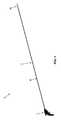
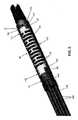
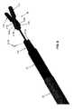
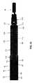
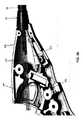
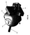
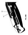
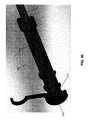
最初に図1、1A、1B、および2を見ると、本発明にしたがって形成された新規な医療用器具5が示されている。新規な医療用器具5は、概して、ハンドル10と、ハンドル10から遠位方向に延在するシャフト15とを備える。シャフト15は、概して、細長い可撓性近位部分20と、可撓性近位部分20の遠位端に取り付けられた遠位側関節接合部分25とを備える。エンドエフェクタ30は、遠位側関節接合部分25の遠位端に取り付けられる。エンドエフェクタ30は、多くの異なる形態を取ってもよい(例えば、把持具、注射針、鋏、熱係蹄、モノポーラプローブ、止血クリップ、バイポーラ鉗子、吸引チューブ、ステープラおよびタッカなどの単発型もしくは多発型閉止デバイス、解剖用鉗子、回収バスケット、モノポーラ鋏など)。例証を明確にするため、エンドエフェクタ30は、図面中では把持具として示される。ハンドル10は、多くの異なる形態のうち任意の1つを取ってもよい(例えば、ピストルグリップ、シャフトグリップなど)。例証を明確にするため、ハンドル10は、図面中ではピストルグリップとして示される。 First looking at FIGS. 1, 1A, 1B, and 2, shows a novel
本発明によれば、シャフト15の可撓性近位部分20は、蛇行経路に沿って顕著な長さ(例えば、95cm〜140cm)を延在することができる可撓性の高い要素であるように構成され、シャフト15の遠位側関節接合部分25は、シャフト15の可撓性近位部分20の遠位端に対して自在に関節接合できるように構成され、エンドエフェクタ30は、遠位側関節接合部分25の遠位端に対して選択的に回転させられるように構成され、選択的に作動させてもよく、全ての機能は、ハンドル10を介してユーザの片手で実施することができる。本発明の好ましい一形態では、医療用器具5のシャフト15のほぼ全体が可撓性であり、シャフト15の移行点32よりも近位側の部分(即ち、可撓性近位部分20)は受動的に可撓性であり(例えば、蛇行経路を辿ることができる)、シャフト15の移行点32よりも遠位側の部分(即ち、遠位側関節接合部分25)は能動的に可撓性である(即ち、所望の構成へと自在に関節接合させることができる)。 According to the present invention, the flexible
以下で更に詳細に記載するように、新規な医療用器具5は少なくとも次の運動を行うことができる。
運動1−ハンドル10の長手方向移動によるエンドエフェクタ30の長手方向移動(本明細書では「長手方向運動機能」と呼ぶ場合がある)
運動2−ハンドル10の回転移動によるエンドエフェクタ30の回転移動(本明細書では「トルク付与運動機能」と呼ぶ場合がある)
運動3−シャフト15の可撓性近位部分20の遠位端に対してシャフト15の遠位側関節接合部分20を関節接合させることによる、エンドエフェクタ30の関節移動(本明細書では「自在関節機能」と呼ぶ場合がある)
運動4−シャフト15に対してエンドエフェクタ30を回転させることによる、シャフト15の遠位側関節接合部分25の遠位端に対するエンドエフェクタ30の回転移動(本明細書では「輪転機能」と呼ぶ場合がある)
運動5−医療処置、例えば把持具タイプのエンドエフェクタの顎部の開閉を実施するように、例えば、エンドエフェクタ30の要素を互いに対して選択的に動かす、エンドエフェクタ30の作動(本明細書では「顎部開閉機能」と呼ぶ場合がある)As described in more detail below, the novel
Motion 1-Vertical movement of the
Motion 2-Rotary movement of the
Exercise 3-Joint movement of the
Motion 4-Rotational movement of the
Exercise 5-Activation of the
2 シャフト15の構造
2.1 可撓性近位部分20
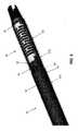
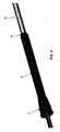
次に図1、1A、1B、および2〜4を見ると、シャフト15の可撓性近位部分20は、概して、遠位端40と、近位端45と、それらの間に延在する管腔50とを有する、細長い可撓性の外側コイル35(図2および3)を備える。シャフト15の遠位側関節接合部分25は、介在要素(後述)を介して、外側コイル35の遠位端40に取り付けられる。外側コイル35の近位端45はシャフトアダプタ55に固着され、それが次いでハンドル10に固着される(後述)。2 Structure of
Next, looking at FIGS. 1, 1A, 1B, and 2-4, the flexible
可撓性近位部分20の遠位端に対して(即ち、外側コイル35の遠位端40に対して)遠位側関節接合部分25を選択的に関節接合させる手段、遠位側関節接合部分25に対してエンドエフェクタ30を選択的に回転させる手段、ならびにエンドエフェクタ30を選択的に作動させる手段は、以下で更に詳細に検討するように、外側コイル35の管腔50を通って延在する。 Distal articulation, a means of selectively articulating the
本発明の好ましい一形態では、剛性チューブ60(図1Aおよび4)が可撓性近位部分20の近位端に設けられ(即ち、外側コイル35の近位端45付近に配設され、シャフトアダプタ55に固着される)、それによって、以下で更に詳細に検討するように、ツール支持器(例えば、台取付け式のツール支持器)に対する新規な医療用器具5の取付けの剛性が増大する領域がもたらされる。所望の場合、剛性チューブ60は、剛性チューブ60の遠位端に、剛性チューブ60の外表面と可撓性近位部分20の剛性チューブ60よりも遠位側に位置する部分の外表面との間の移行部を平滑にする、フィレット65(図4)を備えてもよい。 In a preferred embodiment of the invention, a rigid tube 60 (FIGS. 1A and 4) is provided at the proximal end of the flexible proximal portion 20 (ie, located near the
2.2 遠位側関節接合部分25の概要
上述したように、遠位側関節接合部分25は、可撓性近位部分20の遠位端に対して選択的に関節接合するように構成される。この目的のため、またここで図2および5を見ると、遠位側関節接合部分25は、概して、遠位側関節リンクアセンブリ70と、近位側関節リンクアセンブリ75と、遠位側関節リンクアセンブリ70と近位側関節リンクアセンブリ75との間に延在する屈曲スパイン80とを備える。近位側関節リンクアセンブリ75は、シャフト15の可撓性近位部分20の遠位端に取り付けられると共に、以下で更に詳細に検討するように、遠位側関節リンクアセンブリ70および屈曲スパイン80の選択的な関節接合を可能にする反力面を提供するように構成される。2.2 Overview of the distal
2.2.1 近位側関節リンクアセンブリ75
次に図2および6を見ると、近位側関節リンクアセンブリ75は、可撓性近位部分20の外側コイル35の遠位端40に配設される。近位側関節リンクアセンブリ75の遠位端は、シャフト15の可撓性近位部分20の遠位端に対する遠位側関節リンクアセンブリ70および屈曲スパイン80の選択的な屈曲を可能にする(即ち、遠位側関節接合部分25の自在な関節を有効にするための)反力面を提供する。2.2.1 Proximal
Next, looking at FIGS. 2 and 6, the proximal
より詳細には、近位側関節リンクアセンブリ75(図6)は、以下で更に詳細に検討するように、屈曲スパイン80を係合するように構成された、一対の遠位方向に延在する指90を有する本体85を備える。中央ボア100(図18)の周りに配設される複数のボア95(図6)が本体85に形成され、複数の関節ケーブル(後述)を受け入れるようにサイズ決めされる。所望の場合、ボア95は、それらの近位端に配設された、以下で検討するような関節ケーブルハウジングを受け入れるカウンタボア(図示なし)を備えてもよい。中央ボア100(図18)は、以下で検討するように、その遠位端に配設された、本体85に対する遠位側関節リンクアセンブリ70の取付けを容易にするカウンタボア102(図6および18)を備えてもよい。 More specifically, the proximal joint link assembly 75 (FIG. 6) extends in a pair of distal directions configured to engage the
近位側関節リンクアセンブリ75が、以下で検討するように、シャフト15の遠位側関節接合部分25を選択的に屈曲させる反力面を提供するために、近位側関節リンクアセンブリ75の本体85は、複数の関節ケーブルハウジング235(後述)に接し、それらが次いでハンドル10に接する。外側コイル35は、近位側関節リンクアセンブリ75の本体85に固着されるが、本体85に対して実質的に反力を与えず、本体85に対する反力は関節ケーブルハウジングによって与えられることに留意されたい。 The body of the proximal
2.2.2 遠位側関節リンクアセンブリ70
次に図2、5、および7を見ると、遠位側関節リンクアセンブリ70は、概して、中央開口部110が貫通している本体105(図7)と、そこから近位方向に延在する短いレーザーカットハイポチューブ115とを備える。短いレーザーカットハイポチューブ115は、遠位端120と、近位端125と、それらの間に延在する管腔130とを備える。短いレーザーカットハイポチューブ115は可撓性が高いが、十分なカラム強度を有して構成されるので、以下で検討するように、短いレーザーカットハイポチューブ115の近位端125が近位側関節リンクアセンブリ75の本体85(図6)に接し、偏心近位方向力が本体105に加えられたときに、近位側関節リンクアセンブリ75に対する本体105の選択的関節接合が可能になる。短いレーザーカットハイポチューブ115の近位端125は、(例えば、溶接によって)近位側関節リンクアセンブリ75の本体85に取り付けられる。短いレーザーカットハイポチューブ115の遠位端120は、遠位側関節リンクアセンブリ70がその弛緩(即ち、非付勢)状態のときに、短いレーザーカットハイポチューブ115の管腔130が本体105の中央開口部110と整列される状態で、(例えば、溶接によって)本体105に取り付けられる。この構造の結果として、近位側関節リンクアセンブリ75の本体85の回転によってレーザーカットハイポチューブ115が回転し、それによって遠位側関節リンクアセンブリ70の本体105が回転する。本体105はまた、以下で更に詳細に検討するように、1つ以上の関節ケーブルを本体105に取り付ける、一対の遠位側座部135(そのうち1つのみが図7に示される)を備える。本体105はまた、以下で更に詳細に検討するように、屈曲スパイン80(図5)と噛合する、2つの近位方向に延在する指137を備える。2.2.2 Distal
Next, looking at FIGS. 2, 5, and 7, the distal
2.2.3 屈曲スパイン80
次に図5を見ると、屈曲スパイン80は、概して、遠位端141および近位端142を有する可撓性本体140を備える。複数の軸線方向で整列された開口部145、および中央ボア150が、遠位端141と近位端142との間に延在する。開口部145は、以下で検討するように、関節ケーブルをそれぞれ中に受け入れるようにサイズ決めされる。中央ボア150は、遠位側関節リンクアセンブリ70の短いレーザーカットハイポチューブ115(図7)を受け入れるようにサイズ決めされる。屈曲スパイン80の近位端142は、近位側関節リンクアセンブリ75の上述した遠位方向に延在する指90(図6)を受ける近位側座部155を備え、屈曲スパイン80の遠位端141は、遠位側関節リンクアセンブリ70の上述した近位方向に延在する指137(図7)を受け入れる遠位側座部160を備える。屈曲スパイン80がこのような形で取り付けられると、屈曲スパイン80は遠位側関節リンクアセンブリ70または近位側関節リンクアセンブリ75いずれかに対する回転に対抗して固定されることが理解されるであろう。2.2.3
Next, looking at FIG. 5, the
2.2.4 回転可能なハウジングアセンブリ165
次に図5および8〜12を見ると、遠位側関節接合部分25の遠位端は、以下で検討するように、エンドエフェクタ30を遠位側関節リンクアセンブリ70に回転可能に取り付ける、回転可能なハウジングアセンブリ165(図9)を備える。2.2.4
Next, looking at FIGS. 5 and 8-12, the distal end of the distal articular joint 25 rotatably attaches the
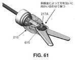
より詳細には、回転可能なハウジングアセンブリ165は、概して、カラー170と、遠位端185、近位端190、およびそれらの間に延在する管腔195を有する長いレーザーカットハイポチューブ180とを備える。回転可能なハウジングアセンブリ165はまた、回転可能なハウジングアセンブリ165がその弛緩(即ち、非付勢)状態のとき、長いレーザーカットハイポチューブ180の管腔195が回転コネクタ200の開口部205と整列されるように、また長いレーザーカットハイポチューブ180および回転コネクタ200がユニットとして回転できるように、長いレーザーカットハイポチューブ180の遠位端185に固定的に取り付けられる、開口部205が形成された回転コネクタ200(図9および10)を備える。エンドエフェクタマウント210(図8、9、11、および12)は、回転コネクタ200が回転すると(即ち、長いレーザーカットハイポチューブ180が回転すると)エンドエフェクタマウント210が回転するように、回転コネクタ200に取り付けられる。エンドエフェクタ30はエンドエフェクタマウント210に取り付けられる(後述参照)。回転コネクタ200およびエンドエフェクタマウント210は、カラー170(図5)を介して、遠位側関節リンクアセンブリ70(図5および7)の本体105に回転可能に取り付けられる。より詳細には、回転コネクタ200(図9)は、カラー170に回転可能に取り付けられ、カラー170に対して回転することができる。エンドエフェクタマウント210は、回転コネクタ200に取り付けられ、回転コネクタ200の遠位側肩部215(図10)を係合する。カラー170は、遠位側関節リンクアセンブリ75(図7)の本体105に固定的に取り付けられる。したがって、エンドエフェクタマウント210(図9)は回転コネクタ200に固定的に取り付けられ、それが次いで長いレーザーカットハイポチューブ180に固定的に接続され、上記サブアセンブリ(エンドエフェクタマウント170、回転コネクタ200、および長いレーザーカットハイポチューブ180)は、カラー170に回転可能に取り付けられ、カラー170は遠位側関節リンクアセンブリ70(図5)に固定的に取り付けられ、長いレーザーカットハイポチューブ180は、屈曲スパイン80の中央ボア150を通って、また近位側関節リンクアセンブリ75の本体85のボア100(図18)を通って延在する。 More specifically, the
2.3 エンドエフェクタ30
エンドエフェクタ30は、多くの異なる形態を取ってもよい(例えば、把持具、注射針、鋏、熱係蹄、モノポーラプローブ、止血クリップ、バイポーラ鉗子、吸引チューブ、ステープラおよびタッカなどの単発型もしくは多発型閉止デバイス、解剖用鉗子、回収バスケット、モノポーラ鋏など)。例証を明確にするため、エンドエフェクタ30は、図面中では把持具として示される。2.3
The
本発明の好ましい一形態では、またここで図8を見ると、エンドエフェクタ30はエンドエフェクタマウント210に取り付けられる。より詳細には、本発明の好ましい一形態では、エンドエフェクタ30は、ピン217Aを介してエンドエフェクタマウント210に枢動的に取り付けられた、2つの向かい合った顎部216、217を有する把持具を備え、ピンは、顎部216、217の穴217Bおよびエンドエフェクタマウント210の穴217Cを貫通する。Uリンク218は、以下で検討するように、Uリンク218に取り付けられたプルワイヤ(後述)の往復移動によって、把持具の向かい合った顎部216、217が互いに対して開閉するようにして、顎部216、217の近位部分に形成されたスロット218B内に配設されるピン218Aを介して顎部216、217に取り付けられる。 In a preferred embodiment of the invention, and also as seen in FIG. 8, the
2.4 関節手段の概要
上述したように、シャフト15はまた、(i)可撓性近位部分20に対して遠位側関節接合部分25(図2)を選択的に関節接合させる手段と、(ii)シャフト15に対して回転可能なハウジングアセンブリ165(図9)を選択的に回転させる、即ちシャフト15に対してエンドエフェクタ30を選択的に回転させる手段と、(iii)エンドエフェクタ30(図8)を選択的に作動させる手段とを備える。上記手段は全て、以下で検討するように、ハンドル10を介して作動させられる。2.4 Overview of articulating means As described above, the
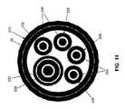
より詳細には、またここで図13および14を見ると、シャフト15は、概して、(i)可撓性近位部分20の遠位端に対して遠位側関節接合部分25を選択的に関節接合させる、4つの関節ケーブル220と、(ii)シャフトに対して回転可能なハウジングアセンブリ165(図9)を選択的に回転させる、即ちシャフト15に対してエンドエフェクタ30を選択的に回転させる、HHSコイル225(例えば、インディアナ州フォートウェイン(Fort Wayne,IN)のFort Wayne Metalsが販売している種類の中空ヘリカルストランド)と、(iii)エンドエフェクタ30を選択的に作動させるプルワイヤ230とを備える。 More specifically, and also here with reference to FIGS. 13 and 14, the
2.4.1 関節ケーブル220
次に図13〜16を見ると、本発明の好ましい形態では、4つの関節ケーブル220は、ハンドル10から遠位側関節リンクアセンブリ70の遠位側座部135(図15および16)まで続き、関節ケーブル220は、本体85(図6)のボア95を通り、屈曲スパイン80(図5)の開口部145を通って、本体105(図16)の遠位側座部135まで延在する。関節ケーブル220は、好ましくは、関節ケーブルハウジング235(図13)内でそれぞれ摺動可能に配設される。関節ケーブルハウジング235の遠位端240は、近位側関節リンクアセンブリ75の本体85(図15)に(即ち、以下で検討するように、ねじアジャスタ330を介して)取り付けられる。関節ケーブルハウジング235は、近位側関節リンクアセンブリ75の本体85に接し、シャフト15の可撓性近位部分25に対するシャフト15の遠位側関節接合部分25の関節のため、本体85に反力を与える。関節ケーブルハウジング235はまた、関節ケーブル220を互いに、またHHSコイル225から分離し、シャフト15の可撓性近位部分20内における(即ち、相当の長さ(例えば、95cm〜140cm)であってもよく、医療用器具5が患者の体内に配設されたときの蛇行経路を辿る、ハンドル10と近位側関節リンクアセンブリ75との間の距離にわたる)関節ケーブル220の滑らかな摺動移動を担保する助けとなる。所望の場合、本体85(図15)に対して関節ケーブルハウジング235の遠位端を取り付けるのを容易にするために、各ボア95の近位端は、所与の関節ケーブルハウジング235の遠位端240を受け入れるようにサイズ決めされたカウンタボア(図示なし)を備えてもよい。2.4.1
Next, looking at FIGS. 13-16, in a preferred embodiment of the invention, the four
次に図15および16を見ると、関節ケーブル220が屈曲スパイン80の開口部145(図5)を遠位方向に貫通した後、関節ケーブル220は、遠位側関節リンクアセンブリ70の本体105の遠位側座部135に(例えば、溶接、圧着などによって)装着される。一例として、ただしそれに限定するものではないが、関節ケーブル220のうち2つは単一の長いケーブルによって提供されてもよく、その単一の長いケーブルにはチューブ245(図16)が圧着され、チューブ245は遠位側座部135に溶接(または別の方法で定着)される。 Next, looking at FIGS. 15 and 16, after the
この構造の結果として、関節ケーブル220の近位端を近位方向に選択的に引っ張ることによって、遠位側関節リンクアセンブリ70の本体105(図7)を横方向に関節接合させ、それによってシャフト15の遠位側関節接合部分25を関節接合させることができる。更に、少なくとも3つの関節ケーブル220を設け、3つ以上の関節ケーブルが本体105の周囲の周りに位置付けられることによって、遠位側関節リンクアセンブリ70の実質的に自在な関節を達成し、それによってシャフト15の遠位側関節接合部分25の実質的に自在な関節をもたらすことができる。 As a result of this structure, the body 105 (FIG. 7) of the distal
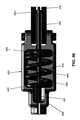
2.4.2 HHSコイル225
次に図13、14、および17を見ると、HHSコイル225は、遠位端250(図17)と、近位端255(図26)と、それらの間に延在する管腔260(図13)とを備える。シャフト15内でのHHSコイル225の回転を容易にするために、HHSコイル225は、好ましくは、可撓性の摩擦低減スリーブ267(図13)内に配設される。より詳細には、HHSコイル225は、好ましくは、中空管状構造を共に形成するように、共に巻回されスエージ加工された複数の糸状体を含む。一例として、ただしそれに限定するものではないが、HHSコイル225は、インディアナ州フォートウェインのFort Wayne Metalsが販売している種類の中空ヘリカルストランドを含んでもよい。本発明の好ましい一形態では、HHSコイル225は、共に巻回されスエージ加工されて単一の可撓性構造となる10の糸状体を含む。HHSコイル225の遠位端250(図17)は、HHSコイル225が回転すると、長いレーザーカットハイポチューブ180(またしたがって、エンドエフェクタ30を保持するエンドエフェクタマウント210)が回転するようにして、スリーブ(もしくは圧着)265(図17)を介して回転可能なハウジングアセンブリ165(図9)の長いレーザーカットハイポチューブ180(図17)に取り付けられる。この構造の結果として、エンドエフェクタ30の回転方向の配置は、HHSコイル225を選択的に回転させ、それによって長いレーザーカットハイポチューブ180を、またしたがってエンドエフェクタ30が固着されたエンドエフェクタマウント210を回転させることによって、調節できることが理解されるであろう。有意には、HHSコイル225および長いレーザーカットハイポチューブ180を使用して、トルクをシャフト15まで伝達することによって、シャフト15が蛇行経路を辿り、また遠位側関節接合部分25がシャフト15の長手方向軸線に対して関節接合していたとしても、シャフト内でトルクを付与するばねエネルギーの蓄積があった場合にそれが最小限に抑えられる。2.4.2
Next, looking at FIGS. 13, 14, and 17, the
2.4.3 プルワイヤ230
次に図13、14、18、および19を見ると、エンドエフェクタ30を選択的に作動させるプルワイヤ230が設けられる。プルワイヤ230(図19)の遠位端はエンドエフェクタ30のUリンク218に固着され、Uリンク218は、エンドエフェクタ30の顎部216、217に摺動可能に取り付けられ、顎部216、217は、プルワイヤ230の往復移動によってエンドエフェクタ30の向かい合った顎部216、217が互いに対して開閉するように、エンドエフェクタマウント210にピンで留められる。2.4.3
Next, looking at FIGS. 13, 14, 18, and 19, a
2.5 シャフト15の構造の更なる詳細
シャフト15が完全に組み立てられると、またここで図18〜23を見ると、近位側関節リンクアセンブリ75(図6)の本体85(図18)は、可撓性外側コイル35の遠位端40(図2)に取り付けられ、関節ケーブルハウジング235の遠位端240(図15)は、近位側関節リンクアセンブリ75の本体85に取り付けられ、関節ケーブル220は、本体85に形成されたボア95(図6)を貫通する。遠位側関節リンクアセンブリ70(図7)は、本体85のカウンタボア102(図6)内で短いレーザーカットハイポチューブ115の近位端125を取り付けることによって、近位側関節リンクアセンブリ75に取り付けられる。屈曲スパイン80の可撓性本体140(図5)は、遠位側関節リンクアセンブリ70の本体105(図7)と近位側リンクアセンブリ75の本体85(図6)との間に「挟まれ」、本体85の遠位方向に延在する指90は屈曲スパイン80の近位側座部155(図5)に配設され、本体105の近位方向に延在する指137は屈曲スパイン80の遠位側座部160に配設される。遠位側関節リンクアセンブリ70の短いレーザーカットハイポチューブ115(図7)は、屈曲スパイン80の可撓性本体140の中央ボア150(図5)を貫通する。関節ケーブル220が近位方向に引っ張られると、短いレーザーカットハイポチューブ115の遠位端が近位側関節リンクアセンブリ75の本体85に接し(それが次いで、関節ケーブルハウジング235に接し)、それによって、シャフト15の遠位側関節接合部分25を選択的に関節接合させる。2.5 Further details of the structure of the
回転可能なハウジングアセンブリ165の長いレーザーカットハイポチューブ180(図9、10、および17)は、長いレーザーカットハイポチューブ180の近位端190(図17)が近位側関節リンクアセンブリ75の本体85を(即ち、本体85のカウンタボア102および中央ボア100を貫通することによって)貫通し、例えばスリーブ265を介して、HHSコイル225(図17)に固着されるように、短いレーザーカットハイポチューブ115(図18)を通って近位方向に延在する。回転可能なハウジングアセンブリ165(図9)のカラー170(図18)は、遠位側関節リンクアセンブリ70の本体105に取り付けられ、遠位側座部135(およびそこに取り付けられた関節ケーブル220の部分)を覆う。回転コネクタ200(図9および10)は、長いレーザーカットハイポチューブ180の遠位端に取り付けられる。回転コネクタ200はまた、エンドエフェクタマウント210に取り付けられる。エンドエフェクタ30はエンドエフェクタマウント210に取り付けられる。この構造の結果として、HHSコイル225を回転させると、長いレーザーカットハイポチューブ180が回転し、回転コネクタ200が回転し、エンドエフェクタマウント210が回転し、それによってエンドエフェクタ30が回転する。 The long laser-cut hypotube 180 (FIGS. 9, 10, and 17) of the
プルワイヤ230(図18)は、HHSコイル225(図13および14)の管腔260を通って遠位方向に、また長いレーザーカットハイポチューブ180の管腔195(図9)を通って遠位方向に延在して、回転コネクタ200から出る。プルワイヤ230の遠位端はエンドエフェクタ30に接続される。この構造の結果として、プルワイヤ230の往復移動によって、把持具の向かい合った顎部216、217(図8)が互いに対して開閉する。 The pullwire 230 (FIG. 18) is distal through
シャフト15の可撓性近位部分20は、好ましくは、保護スリーブまたは外被(例えば、Pebax(登録商標))270(図18、20、および21)で覆われ、保護スリーブまたは外被270の近位端が剛性チューブ60に固着(例えば、結合)され、保護スリーブまたは外被270の遠位端が近位側関節リンクアセンブリ75の本体85に固着(例えば、結合)され、またシャフト15の遠位側関節接合部分25は、好ましくは、保護スリーブまたは外被275(図18および22)で覆われ、保護スリーブまたは外被275の近位端が近位側関節リンクアセンブリ75の本体85に固着(例えば、結合)され、保護スリーブまたは外被275の遠位端が、エンドエフェクタ30の近位部分までおよびその上に延在し、それによってシャフト15を保護し、天然の身体開口部、カニューレ、別の外科用器具の管腔などを介して、患者の体内にシャフト15を簡単に挿入することができるようになる。 The flexible
シャフト15の近位端は、以下で更に詳細に検討するように、関節ケーブル220、HHSコイル225、およびプルワイヤ230を、ハンドル10を使用して選択的に作動させてもよいように、ハンドル10(図1)に取り付けられる。 The proximal end of the
3 ハンドル10の概要
次に図24〜26を見ると、ハンドル10は、概して、内部キャビティ280と、関節ケーブル220を選択的に動かす(またしたがって、シャフト15の遠位側関節接合部分25を選択的に関節接合させる)関節制御アセンブリ285と、関節制御アセンブリ285を所望の位置で選択的にロックする(またしたがって、シャフト15の遠位側関節接合部分25を選択位置でロックする)押し棒ロックアセンブリ290と、HHSコイル225を選択的に回転させる(またしたがって、エンドエフェクタ30を選択的に回転させる)輪転制御アセンブリ295と、プルワイヤ230を選択的に作動させる(またしたがって、エンドエフェクタ30を選択的に作動させる)トリガアセンブリ300とを備える。3 Overview of the
3.1 関節制御アセンブリ285
次に図27〜36を見ると、関節制御アセンブリ285は、概して、ハンドル10の内部キャビティ280内に固定的に取り付けられたボールプレート305(図28)と、ボールプレート305に対して選択的に枢動させるように構成されたサムスティックボールアセンブリ310と、ユーザの親指によって係合されるように構成されたサムスティック315とを備える。3.1
Next, looking at FIGS. 27-36, the
ボールプレート305は、以下で更に詳細に検討するように、複数のねじ付き開口部320(図28)と、押し棒ロックアセンブリ290を受け入れる中央開口部325とを備える。ねじ付き開口部320は、複数のねじ付きアジャスタ330(図29および30)を受け入れるように構成され、それらが次いで、各関節ケーブルハウジング235の近位端(図21および30)に取り付けられる。この構造の結果として、関節ケーブルハウジング235の近位端がボールプレート305に接する(それが次いで、ハンドル10に固定的に取り付けられる)ことにより、関節ケーブル220を近位方向に引っ張ると、関節ケーブルハウジング235が、近位側関節リンクアセンブリ75の本体85に反力を加えることが理解されるであろう。以下で検討するように、関節ケーブル220(図30)が、サムスティックボールアセンブリ310に取り付けられたねじ付きアジャスタを(またしたがって、ボールプレート305のねじ付き開口部320を)貫通してもよいように、各ねじ付きアジャスタ330はその中を貫通する中央管腔を備える。拡大部335(図30)が各関節ケーブル220の近位端に形成され(またはそれに装着され)、それによって関節ケーブル220をサムスティックボールアセンブリ310に装着するのが容易になる。ボールプレート305はまた、以下で更に詳細に検討するように、ハンドル10の内部キャビティ280内に配設された座部342に枢動的に嵌め込まれたサムスティックボールアセンブリ310に遊びを与える、近位側に面する凹状陥凹部340(図29)を備える。 The
サムスティックボールアセンブリ310は、遠位側半球345(図32)と近位側半球350とを備える。遠位側半球345は、好ましくは、遠位側半球345の最大直径(即ち、その遠位端の直径)よりも大きい最大直径(即ち、その近位端の直径)を有し、それによって、遠位側半球345の近位端付近に近位側円周方向座部355(図31)が設けられる。以下で検討するように、拡大部335が近位側円周方向座部355上に嵌め込まれたときに関節ケーブル220を受け入れる、複数の開口部(または溝)360(図31)が、近位側円周方向座部355に形成される。この構造の結果として、遠位側半球345の丸い遠位端が、ハンドル10(図27)の内部キャビティ280の座部342内に枢動的に配設され、ボールプレート305(図33)から離間されると、拡大部335が近位側円周方向座部355上に嵌め込まれるので、関節ケーブル220が、近位側円周方向座部355の開口部(または溝)360を貫通してもよい。したがって、ハンドル10の内部キャビティ280内において遠位側半球345をその座部342内で選択的に枢動させることによって(即ち、以下で更に詳細に検討するように、サムスティック315を選択的に枢動させることによって)、関節ケーブル220を選択的に動かしてもよい。 The
サムスティック315は、ねじ付き軸362(図33)とサムシート363とを備える。ねじ付き軸362の遠位端は、近位側半球350を遠位側半球345に固着する。サムシート363はねじ付き軸362の近位端に固着される。この構造の結果として、サムスティック315を使用して遠位側半球345を選択的に動かし、それによって関節ケーブル220を選択的に動かし、それによって、シャフト15の可撓性近位部分20に対してシャフト15の遠位側関節接合部分25を選択的に関節接合させることができる。 The
3.1.1 押し棒ロックアセンブリ290
次に図27、28、および33〜36を見ると、押し棒ロックアセンブリ290は、概して、作動レバー365(図33)と、作動レバー365に取り付けられたカム370と、押し棒380が取り付けられ、そこから近位方向に延在する押し棒ロックアセンブリプレート375とを備える。押し棒380は、好ましくは、スリーブ385内に配設される。本発明の好ましい一形態では、押し棒ロックアセンブリプレート375をボールプレート305(図36)から離れる方向で遠位側に付勢するのに、ばね390(図35)がスリーブ385の上に配設される。押し棒380は、ボールプレート305の中央開口部325(図28)内に摺動可能に配設され、そこからサムスティックボールアセンブリ310(図33)に向かって近位方向に延在する。作動レバー365およびカム370は、ハンドル10のキャビティ280内に回転可能に取り付けられ、作動レバー365の動きが、押し棒ロックアセンブリプレート375(またしたがって、押し棒380)をばね390の力に対抗して近位方向にカム駆動し、それによって押し棒380の自由端が遠位側半球345を係合して、サムスティックボールアセンブリ310を動きに対抗してロックするように、カム370が押し棒ロックアセンブリプレート375に接触する。作動レバー365を第2の反対方向に動かすと、カム370が動いて、押し棒ロックアセンブリプレート375(またしたがって、押し棒380)を、ばね390の力の下で、遠位側半球345から離れるように遠位方向に動かすことが可能になり、それによってサムスティックボールアセンブリ310の自由移動が可能になる。結果として、押し棒ロックアセンブリ290を使用して、サムスティックボールアセンブリ310を所望の位置で選択的にロックし、それによってシャフト15の遠位側関節接合部分25を所望の(例えば、関節接合)構成で選択的にロックできることが理解されるであろう。3.1.1 Push
Next, looking at FIGS. 27, 28, and 33-36, the push
3.2 輪転制御アセンブリ295
次に図37〜41を見ると、輪転制御アセンブリ295は、概して、キー溝400(図38)が貫通している輪転ノブ395(図37および38)と、輪転キー405とを備える。輪転キー405は、遠位端406と、近位端407と、それらの間に延在する管腔408とを備える。HHSコイル225は、輪転キー405の管腔408内に受け入れられ、輪転キー405の回転がHHSコイル225の回転をもたらすように、輪転キー405に固着される。上述したように、HHSコイル225は長いレーザーカットハイポチューブ180に固着され、長いレーザーカットハイポチューブ180はエンドエフェクタマウント210に固着されるので、HHSコイル225の回転によって長いレーザーカットハイポチューブ180が回転し、それによってエンドエフェクタマウント210の回転(またしたがって、エンドエフェクタ30の回転)が起こる。輪転キー405が輪転ノブ395によって係合され、輪転ノブ395が回転すると回転するように、輪転キー405の遠位端406は、輪転ノブ395のキー溝400に受け入れられる。この構造の結果として、輪転ノブ395の回転によって輪転キー405が回転し、それによってHHSコイル225の回転が、またしたがってエンドエフェクタ30の回転が起こる。本発明の好ましい形態では、輪転ノブ395のキー溝400は、輪転キー405の遠位端406の非円形断面プロファイルに合致する、非円形断面プロファイルを備える。3.2
Next, looking at FIGS. 37-41, the
輪転ノブ395は、輪転ノブ395の一部分がハンドル10(図37)から突き出すことによって、輪転ノブ395をユーザが選択的に回転させることが可能になるように、ハンドル10のキャビティ280内に回転可能に取り付けられる。HHSコイル225内に配設されるプルワイヤ230(図40)は、輪転キー405を通って延在し、以下で検討するように、トリガアセンブリ300(図25)を使用して選択的に作動させられる。 The
輪転キー405の近位端407は輪転ノブ395(図39)の外に延在する。本発明の好ましい一形態では、輪転キー405の近位端407(図38)は、ボールノーズばねプランジャ410(図41)を解放可能に係合する複数の歯409を備える。ボールノーズばねプランジャ410は、ボールノーズばねプランジャ410が輪転キー405の近位端407に配設された歯409を解放可能に係合するように、ハンドル10のキャビティ280内に取り付けられる。ボールノーズばねプランジャ410と輪転キー405との間の係合により、輪転ノブ395を意図して回転させていないときに、輪転キー405(またしたがって、輪転キー405に取り付けられたHHSコイル225)が「偶発的に」回転することが防止される。したがって、ボールノーズばねプランジャ410は、累積したばね張力(例えば、輪転ノブ395を使用してHHSコイル225を回転させたときに蓄積する場合がある、ばね張力)が、HHSコイル225を「解きほぐし」、それによってHHSコイル225の意図しない回転(またしたがって、エンドエフェクタ30の意図しない回転)を引き起こすのを防止する。 The
3.3 トリガアセンブリ300
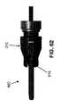
次に図42〜46、46A、46B、および47を見ると、トリガアセンブリ300は、概して、以下で更に詳細に検討するように、トリガ415を作動させると(即ち、引っ張ると)、スレッド420がハンドル10のキャビティ280内で近位方向に移動し、それによってプルワイヤ230を近位方向に移動させ、それによってエンドエフェクタ30を作動させるように、ハンドル10に枢動的に取り付けられたトリガ415と、ハンドル10のキャビティ280内に移動可能に配設されたスレッド420(図43)と、トリガ415をスレッド420に接続する1つ以上のレバーアーム425とを備える。3.3
Next, looking at FIGS. 42-46, 46A, 46B, and 47, the
より詳細には、スレッド420は、キャビティ430(図45)と、キャビティ430内に配設された遠位側ブッシング435(図46)と、キャビティ430内に配設された近位側ブッシング440と、遠位側ブッシング435と近位側ブッシング440の間に配設されたばね445とを備える。内側支持チューブ450は、(例えば、内側支持チューブ450の近位端に配設された圧着スリーブ451によって)プルワイヤ230に固着される。外側支持チューブ452は内側支持チューブ450の遠位部分の上に配設され、内側支持チューブ450は、外側支持チューブ452内で自由に摺動することができる。外側支持チューブ452はまた、ハンドル10の内部キャビティ280に形成された座部454(図46B)内に取り付けられるようにサイズ決めされた、外側支持チューブカラー453を備える。ばね455(図42)は、スレッド420を遠位側に付勢するように、ハンドル10の近位端に配設される。 More specifically, the
この構造の結果として、ばね455(図42)の力に対抗してスレッド420を近位方向に(即ち、トリガ415を引っ張ることによって)動かすと、遠位側ブッシング435(図46)が近位方向に動いてばね445に接し、それが次いで近位側ブッシング440に接し、それが次いで圧着スリーブ451に接し、プルワイヤ230を近位方向に引っ張る。したがって、スレッド420が近位方向に動くにつれて、近位側ブッシング440および圧着スリーブ451も近位方向に動き、それによってプルワイヤ230が近位方向に動いて、エンドエフェクタ30を作動させる。しかしながら、スレッド420がプルワイヤ230に直接取り付けられない限りにおいて、近位側ブッシング440およびばね445は力のリミッタとして作用し、プルワイヤ230に対する力が所与のレベルを超えるとばね445が降伏し、それによって近位方向力がプルワイヤ230に加わらなくなることが理解されるべきである。言い換えると、スレッド420を近位方向に動かすのに加えられた力が、近位側ブッシング440を遠位側ブッシング435から離すように付勢する力(即ち、ばね445によってもたらされる付勢力)を超えた場合、ばね445が縮み、それによって、スレッド420が近位方向に動く際に、近位側ブッシング440および圧着スリーブ451(またしたがって、内側支持チューブ450およびプルワイヤ230)が静止したままであることが可能になる。このように、プルワイヤ230を破壊する危険がなく、トリガ415を「全行程」引っ張ることができる。 As a result of this structure, when the
また、ばね455はスレッド420を遠位方向に付勢し、またスレッド420が近位方向に動くと、圧着スリーブ451は肩部456によって係合されるので、スレッド420はハンドル10内のその遠位位置に戻り、プルワイヤ230は遠位方向に動かされることが理解されるべきである。 Also, the
4 例示の使用方法
低侵襲性処置における新規な医療用器具5の例示的な使用の際、エンドエフェクタ30のプロファイルは縮小され(例えば、エンドエフェクタ30が把持具を備える場合、把持具の顎部を閉じる)、シャフト15を真っ直ぐにし、ハンドル10を、ポータルを通して体内へと(例えば、蛇行経路に沿って)医療用器具5の遠位端を長手方向に前進させるように、長手方向に前進させ、ハンドル10を長手方向に前進および/もしくは回転させ、および/またはシャフト15の遠位側関節接合部分25を曲げ、および/またはエンドエフェクタ30を輪転させ、それによってエンドエフェクタ30で体内部位の標的組織を適切に処理し、エンドエフェクタ30を、体内部位で所望の処置を行うのに使用し(例えば、エンドエフェクタ30が外科用把持具を備える場合、把持具の顎部を開閉して組織を把持する)、ならびに、医療用器具5の遠位端を身体から引き抜き、例えば、ポータルを通してハンドル10を長手方向に引き抜き(その間、必要に応じて、ハンドルは回転もしてもよく、および/またはシャフト15の遠位側関節接合部分25の曲がりを伸ばし、および/またはエンドエフェクタを輪転させる)、それによってエンドエフェクタを身体から引き抜く。4 Illustrative Usage During the exemplary use of the novel
新規な医療用器具5は少なくとも次の運動を行うことができることが理解されるであろう。
運動1−ハンドル10の長手方向移動によるエンドエフェクタ30の長手方向移動(本明細書では「長手方向運動機能」と呼ぶ場合がある)
運動2−ハンドル10の回転移動によるエンドエフェクタ30の回転移動(本明細書では「トルク付与運動機能」と呼ぶ場合がある)
運動3−シャフト15の可撓性近位部分20の遠位端に対してシャフト15の遠位側関節接合部分20を関節接合させることによる、エンドエフェクタ30の関節移動(本明細書では「自在関節機能」と呼ぶ場合がある)
運動4−シャフト15に対してエンドエフェクタ30を回転させることによる、シャフト15の遠位側関節接合部分25の遠位端に対するエンドエフェクタ30の回転移動(本明細書では「輪転機能」と呼ぶ場合がある)
運動5−医療処置、例えば把持具タイプのエンドエフェクタの顎部の開閉を実施するように、例えば、エンドエフェクタ30の要素を互いに対して選択的に動かす、エンドエフェクタ30の作動(本明細書では「顎部開閉機能」と呼ぶ場合がある)
所望の場合、医療用器具は、例えば、輪転機能を排除してもよい、シャフト15の選択的回転などの追加の回転機能を追加してもよいなど、上述の5つより少ない(または、多い)運動を提供するように修正してもよいことが、当業者には理解されるであろう。It will be appreciated that the new
Motion 1-Vertical movement of the
Motion 2-Rotary movement of the
Exercise 3-Joint movement of the
Motion 4-Rotational movement of the
Exercise 5-Activation of the
If desired, the medical device may have less (or more) than the above five, for example, may eliminate the rotary function, may add additional rotational functions such as selective rotation of the
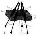
5 新規なツール支持器
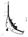
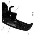
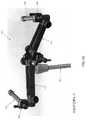
次に図47〜49を見ると、医療用器具5を支持するのに使用されてもよい、新規なツール支持器460が示されている。ツール支持器460は、概して、ツール支持器460を手術台466に取り付ける外科用クランプ465と、1つ以上の医療用器具をツール支持器460に取り付ける調節可能なベース470と、ベース470をクランプ465に調節可能に取り付ける調節可能なアーム475(図48)とを備える。1つ以上の器具アダプタ480(図49)がベース470に取り付けられ、それによって、以下で更に詳細に検討するように、(即ち、シャフト15の近位端にハンドル10および/または剛性チューブ60の支持体を設けることによって)支持ツール支持器460に1つ以上の医療用器具5を取り付けることが可能になる。5 New Tool Supports Next, looking at FIGS. 47-49, shows a
シャフト15を患者の体内(または別の医療用器具の作業管腔)に入れるように構成された1つ以上のツールチャネル485は、以下で更に詳細に検討するように、1つ以上の器具アダプタ480に取り付けられる。 One or
より詳細には、また引き続き図47〜50を見ると、クランプ465は、以下で検討するように、外科医がツール支持器460(またしたがって、それに取り付けられた1つ以上の医療用器具5)を、患者に対して、ならびに/あるいは他の外科用器具に対して操作できるようにするために、固定の対象物に(例えば、手術台466)に取り付けられるように構成される。 More specifically, and continuing to look at FIGS. 47-50, the
調節可能なアーム475は、好ましくは、互いに対して、またクランプ465およびベース470に対して調節可能に取り付けられ、それによって外科医が、患者に対する(および/または別の外科用器具に対する)ベース470の配置を精密に調節できる、1つ以上のセグメント490(図49)を備える。 The
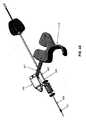
次に図49および50を見ると、器具アダプタ480はそれぞれ、マウント495とチューブ500とを備える。マウント495は、ベース470(図49)に枢動的に取り付けられる。チューブ500は、医療用器具5のシャフト15の近位端(即ち、シャフト15の近位端に位置する剛性チューブ60)を受け入れるようにサイズ決めされた管腔505を有する。所望の場合、管腔505は、チューブ500を流体封止する(またしたがって、ツールチャンバ485を流体封止する)隔壁515を備えてもよく、ならびに/あるいはチューブ500が、チューブ500を流体封止する(またしたがって、ツールチャンバ485を流体封止する)エンドキャップ520を備えてもよい。 Next, looking at FIGS. 49 and 50, the
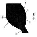
次に図51〜55を見ると、ツール支持器460のいくつかの例示的な構成が示されている。ツール支持器460のベース470は、外科医の要求および/または好みに適応するために、複数のピボットおよび/またはアームを備えてもよく、円弧の形態で形作られてもよく、ならびに/あるいは他の幾何学形状などを含んでもよいことが理解されるべきである。 Next, looking at FIGS. 51-55, some exemplary configurations of the
6 回転可能なシャフト15を備えた医療用器具5
上述したように、新規な医療用器具5は、可撓性近位部分20と、可撓性近位部分20の遠位端に対して選択的に関節接合させることができる遠位側関節接合部分25と、遠位側関節接合部分25の遠位端に対して選択的に回転させることができるエンドエフェクタ30とを有する、シャフト15を備える。この構成で、ハンドル10の長手方向移動を使用して、シャフト15を遠位方向および近位方向に動かし、それによってエンドエフェクタ30遠位方向および近位方向に動かすことができ、ハンドル10の回転移動を使用してシャフト15を回転させ、それによってエンドエフェクタ30を回転させることができ、関節制御アセンブリ285(図25)を使用して、シャフト15の遠位側関節接合部分25を関節接合させ、それによってエンドエフェクタ30の方向を変えることができ、輪転制御アセンブリ295(図25)を使用してエンドエフェクタ30を回転させることができ、トリガアセンブリ300(図25)を使用してエンドエフェクタ30を作動させることができる。上記構成で、可撓性近位部分20はハンドル10と共にユニットとして回転する。6 Medical device with
As mentioned above, the novel
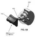
しかしながら、シャフト15の可撓性近位部分20をハンドル10とは独立して回転させることができるのが望ましいことがあると認識されてきた。この目的のため、またここで図56〜58を見ると、新規な回転可能なシャフトアダプタメカニズム525が、シャフト15とハンドル10との間に設けられ、それによってシャフト15(即ち、可撓性近位部分20および遠位側関節接合部分25の両方)をハンドル10に対して選択的に回転させることが可能にされてもよい。 However, it has been recognized that it may be desirable to be able to rotate the flexible
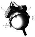
より詳細には、回転可能なシャフトアダプタメカニズム525は、シャフト15の近位端に取り付けられ(即ち、可撓性近位部分20の近位端に取り付けられ)、シャフト15をハンドル10に接続する。本発明のこの形態では、回転可能なシャフトアダプタメカニズム525が上述のシャフトアダプタ55に取って代わる(上述のシャフトアダプタ55がハンドル10に固定的に固着され、外側コイル35の近位端に固定的に固着された場合、また剛性チューブ60がシャフトアダプタ55に固定的に固着された場合)ことが理解されるべきである。より詳細には、本発明のこの形態では、以下で更に詳細に検討するように、シャフト15は、ハンドル10の遠位端に回転可能に取り付けられ、回転可能なシャフトアダプタメカニズム525を介して、回転から選択的にロック/ロック解除される。 More specifically, the rotatable
引き続き図56〜58を見ると、本発明のこの形態では、シャフト15の剛性チューブ60は、剛性チューブ60の最近位端の周りに配設されたフランジ530を備える。フランジ530は、ハンドル10の遠位端に形成された(即ち、ハンドル10の最遠位端付近でハンドル10のキャビティ280内に形成された)対応する溝535内に受け入れられ、それによってシャフト15の剛性チューブ60をハンドル10に回転可能に取り付ける。本発明のこの形態では、外側コイル35の近位端は剛性チューブ60に固定的に固着される(また、外側コイル35の遠位端は、近位側関節リンクアセンブリ75の本体85に固着される)。ハンドル10の最遠位端の外周は、以下で更に詳細に検討するように、回転可能なシャフトアダプタメカニズム525に形成された複数の突出部542を受け入れるようにサイズ決めされた、複数のキー溝540(図57)を備える。所望の場合、キー溝540および突出部542の位置を前記とは逆にしてもよく、即ち、キー溝540は回転可能なシャフトアダプタメカニズム525に形成されてもよく、突出部542はハンドル10の最遠位端に形成されてもよいことに留意されたい。 Continuing to look at FIGS. 56-58, in this embodiment of the invention, the
回転可能なシャフトアダプタメカニズム525は、概して、中を通って延在する管腔550を有するシャフト回転ノブ545を備える。管腔550は、遠位端555と、近位端560と、それらの間に配設された環状肩部565とを備える。ばね570は、環状肩部565と、シャフト15の外周の周りで円周方向に取り付けられた保定キャップ580(図58、58A、58B、58C、および58D)の近位端575との間に延在する、管腔550の遠位端555内に配設され、それによってシャフト回転ノブ545を近位方向に付勢して、シャフトアダプタメカニズム525の突出部542がハンドル10のキー溝540内に受け入れられ、それによってシャフト回転ノブ545を回転に対抗してロックする。より詳細には、保定キャップ580は、シャフト15の剛性チューブ60の外表面上に形成された対応する平坦部590にキー止めする、一対の平坦部585を備える。1つ以上のばね指591は、剛性チューブ60の外表面の溝592を係合し、それによって保定キャップ580を剛性チューブ60にロックする。保定キャップ580はまた、シャフト回転ノブ545の対応するキー溝594に受け入れられるようにサイズ決めされた、複数のキー機構593を備える。この構造の結果として、回転ノブ545は、シャフト15の剛性チューブ60に対して長手方向(遠位方向または近位方向)で摺動することができるが、回転ノブ545は、剛性チューブ60に対する(またしたがって、シャフト15に対する)回転に対抗してロックされる。したがって、剛性チューブ60およびシャフト15の長手方向運動を引き起こさずに、回転ノブ545を長手方向に動かすことができるが、回転ノブ545の回転は剛性チューブ60に(また、以下で検討するように、シャフト15に)伝達される。 The rotatable
シャフト回転ノブ545は、シャフト回転ノブ545が、剛性チューブ60に対して長手方向で移動可能であるが、剛性チューブ60に対して回転的に固定されるように、(例えば、突出部、摩擦嵌めなどによって)シャフト15の剛性チューブ60に接続される。 The
本発明のこの形態では、保護スリーブまたは外被(例えば、Pebax(登録商標))270の近位端は、剛性チューブ60に固着(例えば、結合)され、保護スリーブまたは外被270の遠位端は、近位側関節リンクアセンブリ75の本体85に固着(例えば、結合)される。顕著には、保護スリーブまたは外被270は、剛性チューブ60と近位側関節リンクアセンブリ75の本体85との間でトルクを伝達することができる。 In this embodiment of the invention, the proximal end of the protective sleeve or jacket (eg, Pebax®) 270 is secured (eg, coupled) to the
この構造の結果として、ばね570は通常、シャフト回転ノブ545を近位方向に付勢し、それによって突出部542がキー溝540を係合し、ハンドル10に対する回転に対抗して、シャフト15をロックする。しかしながら、ばね570の力に対抗してシャフト回転ノブ545を遠位方向に動かすと、突出部542がキー溝540から係脱して、ハンドル10に対してシャフト回転ノブ545を選択的に回転させ、それによってハンドル10に対して剛性チューブ60を選択的に回転させ、それによってハンドル10に対して保護スリーブまたは外被270を選択的に回転させ、それによって近位側関節リンクアセンブリ75の本体85を選択的に回転させ、それによってハンドル10に対してシャフト15の遠位側関節接合部分25を選択的に回転させることが可能になる。シャフト15がハンドル10に対して所望の位置まで回転していると、シャフト回転ノブ545は解放され、シャフト回転ノブ545は、突出部542がキー溝540を再係合し、それによってハンドル10に対する更なる回転に対抗してシャフト15をロックするように、ばね570の力の下で近位方向に動く。 As a result of this structure, the spring 570 typically urges the
したがって、本発明のこの形態では、剛性チューブ60は、ハンドル10に対して回転可能であるが、ハンドル10に対して長手方向で固定され、シャフト回転ノブ545は、シャフト回転ノブ545を剛性チューブ60に対して長手方向で動かすことはできるが、剛性チューブ60に対して回転方向では動かすことができないようにして、シャフト回転ノブ545をハンドル10に対して選択的にロックし、またそこからロック解除して、シャフト回転ノブ545が剛性チューブ60を選択的に回転させることができるように、剛性チューブ60に接続され、保護スリーブまたは外被270は、剛性チューブ60と近位側関節リンクアセンブリ75の本体85との間でトルクを伝達して、剛性チューブ60が近位側関節リンクアセンブリ75の本体85を回転させ、それによってハンドル10に対してシャフト15の遠位側関節接合部分25を回転させることが分かるであろう。 Therefore, in this embodiment of the present invention, the
剛性チューブ60およびシャフト15の無制限の回転によって、関節ケーブル220および関節ケーブルハウジング235がそれら自体に巻き付き、したがって、本発明の好ましい一形態では、剛性チューブ60およびシャフト15の回転を制限する手段が提供されることが理解されるであろう。より詳細には、本発明の好ましい一形態では、またここで図58Eおよび58Fを見ると、シャフト15の剛性チューブ60は、好ましくは、シャフト15の外表面の周りで部分的に円周方向に延在する溝595を備える。溝595は、シャフト15の近位端の直ぐ遠位側に配設され、シャフト15の円周の周りに、全体的にではなく部分的に延在する。対応するボス596が、ハンドル10の遠位端に形成され、溝595内に受け入れられる。この構造の結果として、ボス596が溝595の一端に達するまでのみ、シャフト15を回転させることができる。本発明の好ましい形態では、溝580は、シャフト15を最大350度回転させることができるようにサイズ決めされる。 The unlimited rotation of the
7 追加の構造
上述の開示では、ハンドルと、細長い可撓性シャフトと、医療処置を行うように構成された、シャフトの遠位端に配設されたエンドエフェクタとを備える、新規な医療用器具5が記載されている。医療用器具5は、異なるタイプのエンドエフェクタに対応し、医療用器具5の片手使用を容易にして、医療用器具5の機能性を向上させるなどのために、様々な方法で修正されてもよいことが理解されるべきである。7 Additional Structures In the above disclosure, a novel medical device comprising a handle, an elongated flexible shaft, and an end effector located at the distal end of the shaft configured to perform a medical procedure. 5 is described. The
7.1 代替のエンドエフェクタ
上述したように、本発明の好ましい形態では、エンドエフェクタ30は、2つの向かい合った顎部216、217(図8)を有する外科用把持具を備える。7.1 Alternative End Effector As mentioned above, in a preferred embodiment of the invention, the
本発明の別の好ましい形態では、またここで図59〜62を見ると、エンドエフェクタ30は、向かい合った刃605、610を有する鋏600を備える。刃605、610は、刃605、610を合わせた(即ち、閉じた)ときの(例えば、組織、縫合糸などの)切断を容易にするために、互いに接触する鋭いエッジを備える。刃605、610による滑らかな切断を担保するために、刃605、610が合わさって(即ち、閉じて)いるときの刃605、610の互いに対する緊密な接触を維持することが望ましい。この目的のため、斜座金615(図61および62)が、刃605、610の一方とエンドエフェクタマウント210の内壁との間に配設される。斜座金斜座金615は、好ましくは、刃605、610をエンドエフェクタマウント210に枢動的に取り付ける、ピン217Aの上に配設される。この方法で斜座金615を取り付けることによって、刃605、610は、合わさって(即ち、閉じて)いるときは緊密に係合して保たれ、それによって(例えば、組織、縫合糸などの)滑らかな切断が容易になる。 In another preferred embodiment of the invention, also looking here at FIGS. 59-62, the
7.2 片手でシャフト回転するための指のスライド
上述したように、本発明の一形態では、シャフト15は、ハンドル10の遠位端に回転可能に取り付けられ、回転可能なシャフトアダプタメカニズム525(図56〜58および58A〜58F)を使用して、選択的に回転させることができる。本発明のこの形態で、シャフト15の近位端は、(例えば、剛性チューブ60の上述のフランジ530(図58)が、ハンドル10の遠位端に形成された上述の対応する溝535内に回転的に受け入れられることによって)ハンドル10の遠位端に回転的に取り付けられ、回転可能なシャフトアダプタメカニズム525は、シャフト15を「ロック解除」するため(即ち、シャフト回転ノブ545、またしたがってシャフト15が回転できるようにするため)に、遠位方向に動かされる。ユーザは、次に、所望に応じて(即ち、回転可能なシャフトアダプタメカニズム525を回転させ、またしたがってシャフト15を回転させることによって)シャフト15を回転させることができる。ユーザが所望に応じてシャフト15を回転させた後、シャフトアダプタメカニズム525は解放され、近位方向に自動で(即ち、ばね570の力の下で)動いて、更なる回転に対抗してシャフト15を「ロック」する。この作用は、一般的に、ユーザが片手を使用してハンドル10を静止させて保ちながら、ユーザが反対の手を使用して、回転可能なシャフトアダプタメカニズム525を遠位方向に押す(またその後、シャフト15を回転させる)ことを要する。7.2 Finger slide for rotating the shaft with one hand As described above, in one embodiment of the invention, the
しかしながら、ユーザが片手を使用してシャフト15を回転させるのも望ましいことがあることが理解されるべきである。この目的のため、本発明の別の形態では、シャフト15は(例えば、シャフト15の外表面とツールチャネル(例えば、ツールチャネル485(図48)、内視鏡などの別の医療用器具に設けられたツールチャネルの管腔など)の内部との間の摩擦によって)静止して保たれ、ハンドル10は、シャフト15から選択的に回転方向で脱結合され、ハンドル10は、片手を使用して所望の回転位置までユーザによって選択的に回転させられる。次に、ハンドル10は、シャフト15に回転方向で再結合され、次にユーザによって回転させられる(それによってシャフト15も回転させる)。 However, it should be understood that it may also be desirable for the user to use one hand to rotate the
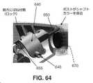
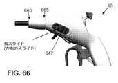
より詳細には、本発明のこの形態で、またここで図63〜66を見ると、以下で更に詳細に検討するように、シャフト15の片手回転を可能にするために、シャフト回転指スライドアセンブリ625が設けられる。シャフト回転指スライドアセンブリ625は、概して、ハンドル10内に摺動可能に配設された指スライドメカニズム630と、シャフト15の近位端に固定的に取り付けられた(例えば、剛性チューブ60に固定的に取り付けられた)シャフトカラー635とを備える。 More specifically, in this embodiment of the invention, and here in FIGS. 63-66, a shaft rotating finger slide assembly to allow one-handed rotation of the
指スライドメカニズム630は、ハンドル10の側壁に形成された対応するスロット(図示なし)を通って延在する、一対の突出部645を有するサドル640を備える。一対の指スライド647は突出部645に固着される。ポスト650は、以下で更に詳細に検討するように、サドル640から遠位方向に延在し、回転に対抗してシャフトカラー635を選択的にロックするように構成される。ばね655は、以下で更に詳細に検討するように、指スライドメカニズム630がその休止状態にあるときは、ポスト650がシャフトカラー635を係合するように、サドル640(またしたがって、ポスト650)を遠位方向に付勢する。 The
シャフトカラー635は、シャフト15の近位端に(例えば、剛性チューブ60に)固定的に取り付けられる。シャフトカラー635は、遠位端660と、近位端665と、それらの間に延在する管腔670とを備える。複数の歯675は、シャフトカラー635の近位端665で管腔670の内周の周りに配設され、以下で更に詳細に検討するように、歯675は、指スライドメカニズム630のポスト650を一対の隣接した歯675の間のギャップ内に受け入れることができるように離間され、それによって、回転に対抗してシャフトカラー635(またしたがって、シャフト15)をロックする。 The
ユーザがシャフト15を回転させたいとき、ユーザは、指スライド647を近位方向に動かし、それによって突出部645を近位方向に動かし、それによってサドル640を、ばね655の力に対抗して近位方向に動かす。これが起こると、ポスト650も近位方向に動かされ、それによってポスト650をシャフトカラー635の歯675から係脱する(またそれにより、ハンドル10をシャフト15から回転的に脱結合する)。突出部645を近位方向で保持しながら、ユーザは、シャフト15に対してハンドル10を所望に応じて回転させることができる。ハンドル10を回転させた際にシャフト15は回転しない(即ち、シャフト15の外表面と、シャフト15が中に配設された管腔、例えばツールチャネル485の内部との摩擦により、シャフト15は静止して維持される)。ユーザがハンドル10を所望の角度まで回転させた後、ユーザは指スライド647を解放し、それによって突出部645およびサドル640(またしたがって、ポスト650)が、ばね655の力の下で遠位方向に動くことが可能になり、ポスト650がシャフトカラー635の一対の歯675の間にある空間内へと遠位方向に動き、それによってハンドル10をシャフトカラー635に(またしたがって、シャフト15)に回転的に再結合する。この時点で、ユーザは、シャフト15を回転させるために、所望に応じてハンドル10を回転させることができる。一例として、ただしそれに限定するものではないが、ユーザがシャフト15を時計方向に90度回転させたい場合、ユーザは、上述したような方法でシャフト15をハンドル10から回転的に脱結合し、ハンドル10を反時計方向に90度回転させ(例えば、ハンドル10のグリップを「6時」の位置から「3時」の位置まで回転させ)、上述したような方法でシャフト15をハンドル10に再結合し、次にハンドル10を(またしたがって、シャフト15を)時計方向に90度回転させる(例えば、ハンドル10のグリップを「3時」の位置から「6時」の位置まで回転させる)ことができる。 When the user wants to rotate the
7.3 単一面関節メカニズム
上述したように、本発明の好ましい一形態では、関節制御アセンブリ285は、4つの関節ケーブル220のうち1つ以上を近位方向に選択的に引っ張るように構成された、サムスティックボールアセンブリ310を備え、それによって、サムスティックボールアセンブリ310の移動を介して、シャフト15の可撓性近位部分20に対する遠位側関節接合部分25の選択的な自在な関節が可能になる。7.3 Single-faced joint mechanism As described above, in a preferred embodiment of the invention, the
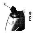
しかしながら、例えば、シャフト15の可撓性近位部分20に対するシャフト15の遠位側関節接合部分25の単一面関節をもたらすのに、関節ケーブルを2つしか使用しなくてもよい単純化した関節制御アセンブリを提供することも、場合によっては望ましいことが認識されてきた。この目的のため、本発明の一形態では、またここで図67〜69を見ると、上述した関節制御アセンブリ285に類似しているが、以下で更に詳細に検討するように、単一面関節をもたらすように構成された、関節制御アセンブリ680が示されている。 However, for example, a simplified joint that requires the use of only two joint cables to provide a single-faced joint of the distal
より詳細には、関節制御アセンブリ680は、ハンドル10の内部キャビティ280内に枢動的に取り付けられるロッカー685を備える。ロッカー685は、ハンドル10の内部キャビティ280内に配設される適切に形成された座部を介して、または他の手段(例えば、ピボットピン)によって、内部キャビティ280内に枢動的に取り付けられてもよい。サムレバー690は、ロッカー685に取り付けられ、ハンドル10(図69)のハウジングに形成されたスロット695を通って近位方向に延在する。楔状のサムレスト700は、好ましくはサムレバー690の自由端に取り付けられる。2つの関節ケーブル220(図示なし)は、(例えば、ロッカー685に形成された対角方向で向かい合ったスロット705内に、関節ケーブル220の近位端を取り付けることによって)ロッカー685に取り付けられる。 More specifically, the
この構造の結果として、ユーザは、サムレバー690を選択的に動かすことによって、単一面内で、シャフト15の遠位側関節接合部分25を選択的に関節接合させ、それによってロッカー685を単一面内で選択的に枢動させることができ、それにより、ロッカー685に取り付けられた2つの関節ケーブル220のうち1つを選択的に近位方向に引っ張る。 As a result of this structure, the user selectively articulates the
7.4 圧縮性外側ラップを備えるHHSコイル
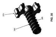
上述したように、プルワイヤ230は、HHSコイル225の管腔260内に配設され、エンドエフェクタ30を選択的に(即ち、ユーザがハンドル10のトリガ415を引っ張り、それによってプルワイヤ230を近位方向に動かしたときに)作動させるために、HHSコイル225に対して自由に摺動することができる。7.4 HHS coil with compressible outer wrap As mentioned above, the
シャフト15(またしたがって、HHSコイル225)が蛇行経路に沿って(例えば、患者の結腸を通って)相当の距離を延在することができる限りにおいて、場合によっては、HHSコイル225が長手方向に縮み(即ち、長手方向で短くなり)、一方でプルワイヤ230が長手方向に縮まない(即ち、長手方向で短くならない)ことが可能であることが見出されている。これが起こると、HHSコイル225はプルワイヤ230の反力をもたらすので、エンドエフェクタ30を作動させるために、プルワイヤ230を更なる距離動かす必要がある。しかしながら、トリガ415がその「行程」の端部に達している場合(即ち、トリガ415をそれ以上引っ張ることができない場合)、プルワイヤ230の更なる近位方向移動は可能ではないことがある。 In some cases, the
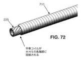
HHSコイル225の長手方向の縮みを最小限に抑えるために、またここで図70〜72を見ると、本発明の一形態では、HHSコイル225の周りに巻回された平巻コイル710が提供される。平巻コイル710は、HHSコイル225の遠位端250に溶接され、HHSコイル225の近位端255に溶接される。コイル710は、HHSコイル225と共に回転し、HHSコイル225を支持し、それによってHHSコイル225の長手方向圧縮を最小限に抑える。この構造の結果として、シャフト15が蛇行経路に沿って配設されたとき、HHSコイル225は長手方向で縮まらない(即ち、HHSコイル225は短くならない)。 In order to minimize longitudinal shrinkage of the
7.5 エンドエフェクタマウント210のカバー
上述したように、エンドエフェクタ30は、把持具のエンドエフェクタおよび顎部216、217を貫通するピン217Aを介して、エンドエフェクタマウント210内で枢動的に取り付けられてもよい。7.5 Cover of
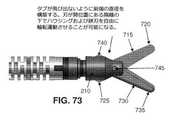
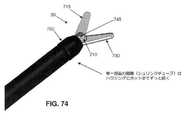
しかしながら、特定のエンドエフェクタでは、エンドエフェクタが特定の構成のときにエンドエフェクタの要素の近位端が動く余地があるように、エンドエフェクタマウント210の側面に開口部を設ける必要がある。一例として、ただしそれに限定するものではないが、ここで図73および74を見ると、本発明の一形態では、エンドエフェクタ30は鋏を含む。より詳細には、本発明のこの形態では、エンドエフェクタ30は、遠位端720および近位端725を有する第1の刃715と、遠位端735および近位端740を有する第2の刃730とを備える。第1の刃715および第2の刃730は、互いに、またピン745を介してエンドエフェクタマウント210に、枢動的に取り付けられる。第1の刃715および第2の刃730が開いているとき(即ち、切断されるべき、組織、縫合糸などを受け入れるため)、第1の刃715の近位端725および第2の刃730の近位端740は、エンドエフェクタマウント210から横方向に突き出す(図73)。近位端725、740は、エンドエフェクタ30が外科処置で使用されているとき、特に刃715、730がそれらの開位置にある状態で、エンドエフェクタ30を手術部位で回転させたとき、周囲の器具および/または解剖学的構造を損傷する恐れがある尖った表面をもたらす場合があることが見出されている。この問題を排除するため、エンドエフェクタマウント210の近位部分を覆うカバー750が設けられてもよい。結果として、刃715、730がそれらの開位置にあるときであっても、刃715、730の近位端725、740は覆われたままであり、それによって解剖学的構造または他の外科用器具への損傷が防止される。本発明の好ましい一形態では、カバー750は、カバー750も電気絶縁をもたらすように、電気絶縁性材料から形成される。これは、エンドエフェクタ30がモノポーラ鋏などを含む場合に有利であり得る。 However, for certain end effectors, it is necessary to provide an opening on the side surface of the
7.6 改善したハンドルおよびトリガのエルゴノミクス
上述したように、本発明の好ましい一形態では、トリガ415(図25)は、ハンドル10に枢動的に取り付けられ、エンドエフェクタ30を選択的に作動させるためにユーザによって選択的に引っ張られてもよい。例証の目的で、トリガ415は、図25では、従来の「ピストル型」トリガとして示されており、ハンドル10は従来の「ピストル型」グリップを含むものとして示されている。7.6 Improved handle and trigger ergonomics As mentioned above, in a preferred embodiment of the invention, the trigger 415 (FIG. 25) is pivotally attached to the
しかしながら、場合によっては、(例えば、医療用器具5の片手使用を容易にするため)ハンドル10に追加の安定化要素を設けること、および/またはより良好なてこ比を提供するのにより長い行程を有する(即ち、移動の円弧が増大した)トリガを設けることが望ましいことが見出されている。 However, in some cases (eg, to facilitate one-handed use of the medical device 5), the
これらの目的のため、またここで図75および76を見ると、本発明の一形態では、ハンドル10は、ユーザの「小指」を受け入れる「小指」安定リング755と、より大きいてこ比および優れたエルゴノミクスをユーザに提供する「シェパードのフック」タイプのトリガ760とを備える。この構造により、ユーザがハンドル10をより良好に片手で握ることが容易になり、またユーザが、(例えば、把持具の顎部を選択的に開閉するために、プルワイヤ230を引っ張るかまたは押すのに)トリガ415を簡単に近位方向または遠位方向に動かすことが可能になる。 For these purposes, and also here with reference to FIGS. 75 and 76, in one embodiment of the invention, the
7.7 単極電流送達
一部の状況では、単極電力をエンドエフェクタ30に送達できることが望ましい。一例として、ただしそれに限定するものではないが、エンドエフェクタ30が単極(「熱」)鋏を含む場合、電力をハンドル10からシャフト15に沿って(もしくはそこを通して)エンドエフェクタ30まで伝達する必要がある。7.7 Unipolar Current Delivery In some situations, it is desirable to be able to deliver unipolar power to the
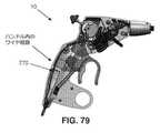
その目的のため、またここで図77〜80を見ると、本発明の好ましい一形態では、外部電源(図示なし)に接続するための、ハンドル10のグリップの近位端に配設された電気接続ポート(例えば、「バナナジャック」)765と、電力を電気接続ポート765からハンドル10(図80)内に配設された導電性板ばね775まで送る、ハンドル10の内部キャビティ280内に配設されたワイヤ770(図79)とが提供される。導電性板ばね775は、輪転キー405上に配設された複数の歯409に接触し、それによって輪転キー405と、またしたがって輪転キー405を介してHHSコイル225および/またはプルワイヤ230と電気的に接触する。本発明のこの形態で、ボールノーズばねプランジャ410は、好ましくは省略される(即ち、導電性板ばね775に置き換えられる)ことが理解されるべきである。それに加えて、本発明のこの形態で、輪転キー405(および輪転キー405の歯409)は、長いレーザーカットハイポチューブ180、回転コネクタ200、およびエンドエフェクタマウント210と同様に、導電性材料(例えば、金属)で形成される。結果として、電力は、外部電源(図示なし)から電気接続ポート765に、ワイヤ770に沿って導電性板ばね775に、導電性ばね775から輪転キー405に、次にHHSコイル225に(また、プルワイヤ230にも)、HHSコイル225(およびプルワイヤ230)に沿ってシャフト15の可撓性近位部分20を通して、スリーブ(もしくは圧着)265を通して長いレーザーカットハイポチューブ180に、長いレーザーカットハイポチューブ180(およびプルワイヤ230)に沿ってシャフト15の遠位側関節接合部分25を通って、回転コネクタ200およびエンドエフェクタマウント210に、またエンドエフェクタマウント210からエンドエフェクタ30に進むことができる。このように、単極電力をエンドエフェクタ30に供給することができる。 For that purpose, and here in FIGS. 77-80, in a preferred embodiment of the invention, electricity is located at the proximal end of the grip of the
好ましい実施形態の修正
本発明の性質を説明するために本明細書に記載し例証してきた、部分の詳細、材料、ステップ、および構成における多くの追加の変更が、本発明の原理および範囲内にあるままで、当業者によって行われてもよいことが理解されるべきである。
以上説明したように、本発明は以下の形態を有する。
形態1
ツールを備え、前記ツールが、
遠位端および近位端を有するシャフトと、
前記シャフトの前記近位端に装着されたハンドルと、
前記シャフトの前記遠位端に装着されたエンドエフェクタとを備え、
前記シャフトが、前記シャフトの前記近位端から遠位方向に延在する可撓性部分と、前記シャフトの前記遠位端から近位方向に延在する関節接合部分とを備え、前記関節接合部分が可撓性スパインを備え、
複数の関節ケーブルが前記シャフトを通って前記ハンドルから前記可撓性スパインまで延在し、前記複数の関節ケーブルのうち少なくとも1つに張力が加えられると、関節ケーブルハウジングが前記可撓性スパインに対して反力を与えながら前記可撓性スパインが曲がるように、前記複数の関節ケーブルがそれぞれ、前記関節ケーブルの周りに配設された前記関節ケーブルハウジングを有し、
回転可能な要素を回転させると前記エンドエフェクタが回転するように、前記回転可能な要素が前記シャフトを通って前記ハンドルから前記エンドエフェクタまで延在し、
作動要素を動かすと前記エンドエフェクタが作動するように、前記作動要素が前記シャフトを通って前記ハンドルから前記エンドエフェクタまで延在する、低侵襲性処置を行う装置。
形態2
前記シャフトの前記可撓性部分が、前記可撓性スパインに固着された外側コイルを備える、形態1に記載の装置。
形態3
前記複数の関節ケーブルのうち少なくとも1つに張力が加えられると、前記関節ケーブルハウジングが前記反力の実質的に全てを前記可撓性スパインに与え、前記外側コイルは前記反力を実質的に全く前記可撓性スパインに与えない、形態2に記載の装置。
形態4
剛性チューブの回転によって外被が回転し、前記外被の回転によって前記可撓性スパインが回転するようにして、前記ハンドルに対して回転するように構成された剛性チューブと、前記剛性チューブおよび前記可撓性スパインに固着された前記外被とを更に備える、形態2に記載の装置。
形態5
前記回転可能な要素が、前記ハンドルから遠位方向に延在する中空管状構造を備え、前記中空管状構造が、共に巻回されスエージ加工された複数の糸状体から形成される、形態1に記載の装置。
形態6
前記回転可能な要素が、前記中空管状構造を回転させるとレーザーカットハイポチューブも回転するようにして、前記中空管状構造に固着されたレーザーカットハイポチューブを更に備える、形態5に記載の装置。
形態7
前記作動要素がプルワイヤを含む、形態1に記載の装置。
形態8
前記エンドエフェクタが、把持具、注射針、鋏、熱係蹄、モノポーラプローブ、止血クリップ、バイポーラ鉗子、吸引チューブ、ステープラおよびタッカなどの単発型もしくは多発型閉止デバイス、解剖用鉗子、回収バスケット、ならびにモノポーラ鋏から成る群から選択された1つを含む、形態1に記載の装置。
形態9
前記シャフトの前記近位端が剛性部分を更に備え、前記装置が、患者支持部に取り付けられたツール支持器を更に備え、前記ツール支持器が前記剛性部分を受け入れる開口部を備える、形態1に記載の装置。
形態10
低侵襲性処置を行う装置を得るステップであって、前記装置が、
ツールを備え、前記ツールが、
遠位端および近位端を有するシャフトと、
前記シャフトの前記近位端に装着されたハンドルと、
前記シャフトの前記遠位端に装着されたエンドエフェクタとを備え、
前記シャフトが、前記シャフトの前記近位端から遠位方向に延在する可撓性部分と、前記シャフトの前記遠位端から近位方向に延在する関節接合部分とを備え、前記関節接合部分が可撓性スパインを備え、
複数の関節ケーブルが前記シャフトを通って前記ハンドルから前記可撓性スパインまで延在し、前記複数の関節ケーブルのうち少なくとも1つに張力が加えられると、関節ケーブルハウジングが前記可撓性スパインに対して反力を与えながら前記可撓性スパインが曲がるように、前記複数の関節ケーブルがそれぞれ、前記関節ケーブルの周りに配設された前記関節ケーブルハウジングを有し、
回転可能な要素を回転させると前記エンドエフェクタが回転するように、前記回転可能な要素が前記シャフトを通って前記ハンドルから前記エンドエフェクタまで延在し、
作動要素を動かすと前記エンドエフェクタが作動するように、前記作動要素が前記シャフトを通って前記ハンドルから前記エンドエフェクタまで延在する、ステップと、
前記装置を使用して低侵襲性処置を行うステップとを含む、低侵襲性処置を行う方法。
形態11
ツールを備え、前記ツールが、
遠位端および近位端を有するシャフトと、
前記シャフトの前記近位端に装着されたハンドルと、
前記シャフトの前記遠位端に装着されたエンドエフェクタとを備え、
前記シャフトが、前記シャフトの前記近位端から遠位方向に延在する可撓性部分と、前記シャフトの前記遠位端から近位方向に延在する関節接合部分とを備え、前記関節接合部分が可撓性スパインを備え、
複数の関節ケーブルのうち少なくとも1つに張力が加えられると前記可撓性スパインが曲がるように、前記複数の関節ケーブルが前記シャフトを通って前記ハンドルから前記可撓性スパインまで延在し、
回転可能な要素を回転させると前記エンドエフェクタが回転するように、前記回転可能な要素が前記シャフトを通って前記ハンドルから前記エンドエフェクタまで延在し、前記回転可能な要素が、前記ハンドルから遠位方向に延在する中空管状構造を備え、前記中空管状構造が、共に巻回されスエージ加工された複数の糸状体から形成され、更に、前記回転可能な要素が、前記中空管状構造を回転させるとレーザーカットハイポチューブも回転するようにして、前記中空管状構造に固着されたレーザーカットハイポチューブを更に備え、
作動要素を動かすと前記エンドエフェクタが作動するように、前記作動要素が前記シャフトを通って前記ハンドルから前記エンドエフェクタまで延在する、低侵襲性処置を行う装置。
形態12
前記シャフトの前記可撓性部分が、前記可撓性スパインに固着された外側コイルを備える、形態11に記載の装置。
形態13
前記複数の関節ケーブルのうち少なくとも1つに張力が加えられると、前記関節ケーブルハウジングが前記反力の実質的に全てを前記可撓性スパインに与え、前記外側コイルが前記反力を実質的に全く前記可撓性スパインに与えないように、前記複数の関節ケーブルがそれぞれ、前記関節ケーブルの周りに配設された関節ケーブルハウジングを有する、形態12に記載の装置。
形態14
剛性チューブの回転によって外被が回転し、前記外被の回転によって前記可撓性スパインが回転するようにして、前記ハンドルに対して回転するように構成された剛性チューブと、前記剛性チューブおよび前記可撓性スパインに固着された前記外被とを更に備える、形態12に記載の装置。
形態15
前記作動要素がプルワイヤを含む、形態11に記載の装置。
形態16
前記エンドエフェクタが、把持具、注射針、鋏、熱係蹄、モノポーラプローブ、止血クリップ、バイポーラ鉗子、吸引チューブ、ステープラおよびタッカなどの単発型もしくは多発型閉止デバイス、解剖用鉗子、回収バスケット、ならびにモノポーラ鋏から成る群から選択された1つを含む、形態11に記載の装置。
形態17
前記シャフトの前記近位端が剛性部分を更に備え、前記装置が、患者支持部に取り付けられたツール支持器を更に備え、前記ツール支持器が前記剛性部分を受け入れる開口部を備える、形態11に記載の装置。
形態18
低侵襲性処置を行う装置を得るステップであって、前記装置が、
ツールを備え、前記ツールが、
遠位端および近位端を有するシャフトと、
前記シャフトの前記近位端に装着されたハンドルと、
前記シャフトの前記遠位端に装着されたエンドエフェクタとを備え、
前記シャフトが、前記シャフトの前記近位端から遠位方向に延在する可撓性部分と、前記シャフトの前記遠位端から近位方向に延在する関節接合部分とを備え、前記関節接合部分が可撓性スパインを備え、
複数の関節ケーブルのうち少なくとも1つに張力が加えられると前記可撓性スパインが曲がるように、前記複数の関節ケーブルが前記シャフトを通って前記ハンドルから前記可撓性スパインまで延在し、
回転可能な要素を回転させると前記エンドエフェクタが回転するように、前記回転可能な要素が前記シャフトを通って前記ハンドルから前記エンドエフェクタまで延在し、前記回転可能な要素が、前記ハンドルから遠位方向に延在する中空管状構造を備え、前記中空管状構造が、共に巻回されスエージ加工された複数の糸状体から形成され、更に、前記中空管状構造を回転させるとレーザーカットハイポチューブも回転するようにして、前記中空管状構造に固着されたレーザーカットハイポチューブを更に備え、
作動要素を動かすと前記エンドエフェクタが作動するように、前記作動要素が前記シャフトを通って前記ハンドルから前記エンドエフェクタまで延在する、ステップと、
前記装置を使用して低侵襲性処置を行うステップとを含む、低侵襲性処置を行う方法。
形態19
ツールを備え、前記ツールが、
遠位端および近位端を有するシャフトと、
前記シャフトの前記近位端に装着されたハンドルと、
前記シャフトの前記遠位端に装着されたエンドエフェクタとを備え、
前記シャフトが、前記シャフトの前記近位端から遠位方向に延在する可撓性部分と、前記シャフトの前記遠位端から近位方向に延在する関節接合部分とを備え、前記関節接合部分が可撓性スパインを備え、
複数の関節ケーブルのうち少なくとも1つに張力が加えられると前記可撓性スパインが曲がるように、前記複数の関節ケーブルが前記シャフトを通って前記ハンドルから前記可撓性スパインまで延在し、
回転可能な要素を回転させると前記エンドエフェクタが回転するように、前記回転可能な要素が前記シャフトを通って前記ハンドルから前記エンドエフェクタまで延在し、
作動要素を動かすと前記エンドエフェクタが作動するように、前記作動要素が前記シャフトを通って前記ハンドルから前記エンドエフェクタまで延在し、
前記シャフトの前記可撓性部分が、前記可撓性スパインに固着された外側コイルを備えると共に、剛性チューブの回転によって外被が回転し、外被の回転によって可撓性スパインが回転するようにして、前記ハンドルに対して回転するように構成された剛性チューブと、前記剛性チューブおよび前記可撓性スパインに固着された前記外被とを備える、低侵襲性処置を行う装置。
形態20
前記複数の関節ケーブルのうち少なくとも1つに張力が加えられると、関節ケーブルハウジングが前記反力の実質的に全てを前記可撓性スパインに与え、前記外側コイルが前記反力を実質的に全く前記可撓性スパインに与えないように、前記複数の関節ケーブルがそれぞれ、前記関節ケーブルの周りに配設された関節ケーブルハウジングを有する、形態19に記載の装置。
形態21
前記回転可能な要素が、前記ハンドルから遠位方向に延在する中空管状構造を備え、前記中空管状構造が、共に巻回されスエージ加工された複数の糸状体から形成される、形態19に記載の装置。
形態22
前記回転可能な要素が、前記中空管状構造を回転させるとレーザーカットハイポチューブも回転するようにして、前記中空管状構造に固着されたレーザーカットハイポチューブを更に備える、形態21に記載の装置。
形態23
前記作動要素がプルワイヤを含む、形態19に記載の装置。
形態24
前記エンドエフェクタが、把持具、注射針、鋏、熱係蹄、モノポーラプローブ、止血クリップ、バイポーラ鉗子、吸引チューブ、ステープラおよびタッカなどの単発型もしくは多発型閉止デバイス、解剖用鉗子、回収バスケット、ならびにモノポーラ鋏から成る群から選択された1つを含む、形態19に記載の装置。
形態25
前記シャフトの前記近位端が剛性部分を更に備え、前記装置が、患者支持部に取り付けられたツール支持器を更に備え、前記ツール支持器が前記剛性部分を受け入れる開口部を備える、形態19に記載の装置。
形態26
低侵襲性処置を行う装置を得るステップであって、前記装置が、
ツールを備え、前記ツールが、
遠位端および近位端を有するシャフトと、
前記シャフトの前記近位端に装着されたハンドルと、
前記シャフトの前記遠位端に装着されたエンドエフェクタとを備え、
前記シャフトが、前記シャフトの前記近位端から遠位方向に延在する可撓性部分と、前記シャフトの前記遠位端から近位方向に延在する関節接合部分とを備え、前記関節接合部分が可撓性スパインを備え、
複数の関節ケーブルのうち少なくとも1つに張力が加えられると前記可撓性スパインが曲がるように、前記複数の関節ケーブルが前記シャフトを通って前記ハンドルから前記可撓性スパインまで延在し、
回転可能な要素を回転させると前記エンドエフェクタが回転するように、前記回転可能な要素が前記シャフトを通って前記ハンドルから前記エンドエフェクタまで延在し、
作動要素を動かすと前記エンドエフェクタが作動するように、前記作動要素が前記シャフトを通って前記ハンドルから前記エンドエフェクタまで延在し、
前記シャフトの前記可撓性部分が、前記可撓性スパインに固着された外側コイルを備えると共に、剛性チューブの回転によって前記外被が回転し、外被の回転によって前記可撓性スパインが回転するようにして、前記ハンドルに対して回転するように構成された剛性チューブと、前記剛性チューブおよび前記可撓性スパインに固着された外被とを備える、ステップと、
前記装置を使用して低侵襲性処置を行うステップとを含む、低侵襲性処置を行う方法。
形態27
ツールを備え、前記ツールが、
遠位端および近位端を有するシャフトと、
前記シャフトの前記近位端に装着されたハンドルと、
前記シャフトの前記遠位端に装着されたエンドエフェクタとを備え、
前記シャフトが、前記シャフトの前記近位端から遠位方向に延在する可撓性部分と、前記シャフトの前記遠位端から近位方向に延在する関節接合部分とを備え、前記関節接合部分が可撓性スパインを備え、
複数の関節ケーブルのうち少なくとも1つに張力が加えられると前記可撓性スパインが曲がるように、前記複数の関節ケーブルが前記シャフトを通って前記ハンドルから前記可撓性スパインまで延在し、
回転可能な要素を回転させると前記エンドエフェクタが回転するように、前記回転可能な要素が前記シャフトを通って前記ハンドルから前記エンドエフェクタまで延在し、
作動要素を動かすと前記エンドエフェクタが作動するように、前記作動要素が前記シャフトを通って前記ハンドルから前記エンドエフェクタまで延在し、
前記シャフトの前記近位端が剛性部分を更に備え、装置が、患者支持部に取り付けられたツール支持器を更に備え、前記ツール支持器が前記剛性部分を受け入れる開口部を備える、低侵襲性処置を行う装置。
形態28
前記シャフトの前記可撓性部分が、前記可撓性スパインに固着された外側コイルを備える、形態27に記載の装置。
形態29
前記複数の関節ケーブルのうち少なくとも1つに張力が加えられると、関節ケーブルハウジングが前記反力の実質的に全てを前記可撓性スパインに与え、前記外側コイルが前記反力を実質的に全く前記可撓性スパインに与えないように、前記複数の関節ケーブルがそれぞれ、前記関節ケーブルの周りに配設された関節ケーブルハウジングを有する、形態28に記載の装置。
形態30
剛性チューブの回転によって外側回転が回転し、外側回転の回転によって前記可撓性スパインが回転するようにして、前記ハンドルに対して回転するように構成された剛性チューブと、前記剛性チューブおよび前記可撓性スパインに固着された外被とを更に備える、形態28に記載の装置。
形態31
前記回転可能な要素が、前記ハンドルから遠位方向に延在する中空管状構造を備え、前記中空管状構造が、共に巻回されスエージ加工された複数の糸状体から形成される、形態27に記載の装置。
形態32
前記回転可能な要素が、前記中空管状構造を回転させるとレーザーカットハイポチューブも回転するようにして、前記中空管状構造に固着されたレーザーカットハイポチューブを更に備える、形態31に記載の装置。
形態33
前記作動要素がプルワイヤを含む、形態27に記載の装置。
形態34
前記エンドエフェクタが、把持具、注射針、鋏、熱係蹄、モノポーラプローブ、止血クリップ、バイポーラ鉗子、吸引チューブ、ステープラおよびタッカなどの単発型もしくは多発型閉止デバイス、解剖用鉗子、回収バスケット、ならびにモノポーラ鋏から成る群から選択された1つを含む、形態27に記載の装置。
形態35
低侵襲性処置を行う装置を得るステップであって、前記装置が、
ツールを備え、前記ツールが、
遠位端および近位端を有するシャフトと、
前記シャフトの前記近位端に装着されたハンドルと、
前記シャフトの前記遠位端に装着されたエンドエフェクタとを備え、
前記シャフトが、前記シャフトの前記近位端から遠位方向に延在する可撓性部分と、前記シャフトの前記遠位端から近位方向に延在する関節接合部分とを備え、前記関節接合部分が可撓性スパインを備え、
複数の関節ケーブルのうち少なくとも1つに張力が加えられると前記可撓性スパインが曲がるように、複数の関節ケーブルが前記シャフトを通って前記ハンドルから前記可撓性スパインまで延在し、
回転可能な要素を回転させると前記エンドエフェクタが回転するように、前記回転可能な要素が前記シャフトを通って前記ハンドルから前記エンドエフェクタまで延在し、
作動要素を動かすと前記エンドエフェクタが作動するように、前記作動要素が前記シャフトを通って前記ハンドルから前記エンドエフェクタまで延在し、
前記シャフトの前記近位端が剛性部分を更に備え、装置が、患者支持部に取り付けられたツール支持器を更に備え、前記ツール支持器が前記剛性部分を受け入れる開口部を備える、ステップと、
前記装置を使用して低侵襲性処置を行うステップとを含む、低侵襲性処置を行う方法。
形態36
ツールを備え、前記ツールが、
遠位端および近位端を有するシャフトと、
前記シャフトの前記近位端に装着されたハンドルと、
前記シャフトの前記遠位端に装着されたエンドエフェクタとを備え、
前記シャフトが、前記シャフトの前記近位端から遠位方向に延在する可撓性部分と、前記シャフトの前記遠位端から近位方向に延在する関節接合部分とを備え、前記関節接合部分が可撓性スパインを備え、
複数の関節ケーブルのうち少なくとも1つに張力が加えられると前記可撓性スパインが曲がるように、前記複数の関節ケーブルが前記シャフトを通って前記ハンドルから前記可撓性スパインまで延在し、
回転可能な要素を回転させると前記エンドエフェクタが回転するように、前記回転可能な要素が前記シャフトを通って前記ハンドルから前記エンドエフェクタまで延在し、
作動要素を動かすと前記エンドエフェクタが作動するように、前記作動要素が前記シャフトを通って前記ハンドルから前記エンドエフェクタまで延在し、
前記関節接合部分が関節接合されていると、前記シャフト内にばねエネルギーが蓄積することなく前記回転可能な要素の回転が起こるように、前記シャフトが構成される、低侵襲性処置を行う装置。
形態37
低侵襲性処置を行う装置を得るステップであって、前記装置が、
ツールを備え、前記ツールが、
遠位端および近位端を有するシャフトと、
前記シャフトの前記近位端に装着されたハンドルと、
前記シャフトの前記遠位端に装着されたエンドエフェクタとを備え、
前記シャフトが、前記シャフトの前記近位端から遠位方向に延在する可撓性部分と、前記シャフトの前記遠位端から近位方向に延在する関節接合部分とを備え、前記関節接合部分が可撓性スパインを備え、
複数の関節ケーブルのうち少なくとも1つに張力が加えられると前記可撓性スパインが曲がるように、前記複数の関節ケーブルが前記シャフトを通って前記ハンドルから前記可撓性スパインまで延在し、
回転可能な要素を回転させると前記エンドエフェクタが回転するように、前記回転可能な要素が前記シャフトを通って前記ハンドルから前記エンドエフェクタまで延在し、
作動要素を動かすと前記エンドエフェクタが作動するように、前記作動要素が前記シャフトを通って前記ハンドルから前記エンドエフェクタまで延在し、
前記関節接合部分が関節接合されていると、前記シャフト内にばねエネルギーが蓄積することなく前記回転可能な要素の回転が起こるように、前記シャフトが構成される、ステップと、
前記装置を使用して低侵襲性処置を行うステップとを含む、低侵襲性処置を行う方法。
形態38
ツールを備え、前記ツールが、
遠位端および近位端を有するシャフトと、
前記シャフトの前記近位端に装着されたハンドルと、
前記シャフトの前記遠位端に装着されたエンドエフェクタとを備え、
前記シャフトが、前記シャフトの前記近位端から遠位方向に延在する可撓性部分と、前記シャフトの前記遠位端から近位方向に延在する関節接合部分とを備え、前記関節接合部分が可撓性スパインを備え、
複数の関節ケーブルのうち少なくとも1つに張力が加えられると前記可撓性スパインが曲がるように、前記複数の関節ケーブルが前記シャフトを通って前記ハンドルから前記可撓性スパインまで延在し、
回転可能な要素を回転させると前記エンドエフェクタが回転するように、前記回転可能な要素が前記シャフトを通って前記ハンドルから前記エンドエフェクタまで延在し、
作動要素を動かすと前記エンドエフェクタが作動するように、前記作動要素が前記シャフトを通って前記ハンドルから前記エンドエフェクタまで延在する、低侵襲性処置を行う装置。
形態39
低侵襲性処置を行う装置を得るステップであって、前記装置が、
ツールを備え、前記ツールが、
遠位端および近位端を有するシャフトと、
前記シャフトの前記近位端に装着されたハンドルと、
前記シャフトの前記遠位端に装着されたエンドエフェクタとを備え、
前記シャフトが、前記シャフトの前記近位端から遠位方向に延在する可撓性部分と、前記シャフトの前記遠位端から近位方向に延在する関節接合部分とを備え、前記関節接合部分が可撓性スパインを備え、
複数の関節ケーブルのうち少なくとも1つに張力が加えられると前記可撓性スパインが曲がるように、前記複数の関節ケーブルが前記シャフトを通って前記ハンドルから前記可撓性スパインまで延在し、
回転可能な要素を回転させると前記エンドエフェクタが回転するように、前記回転可能な要素が前記シャフトを通って前記ハンドルから前記エンドエフェクタまで延在し、
作動要素を動かすと前記エンドエフェクタが作動するように、前記作動要素が前記シャフトを通って前記ハンドルから前記エンドエフェクタまで延在する、ステップと、
前記装置を使用して低侵襲性処置を行うステップとを含む、低侵襲性処置を行う方法。Modifications of Preferred Embodiments Many additional changes in the details, materials, steps, and configurations of the parts described and illustrated herein to illustrate the properties of the invention are within the principles and scope of the invention. It should be understood that it may be done by one of ordinary skill in the art as it is.
As described above, the present invention has the following forms.
Form 1
Equipped with a tool, the tool
Shafts with distal and proximal ends,
A handle attached to the proximal end of the shaft and
With an end effector mounted on the distal end of the shaft
The shaft comprises a flexible portion extending distally from the proximal end of the shaft and a joint joint portion extending proximally from the distal end of the shaft. The part has a flexible spine,
When a plurality of joint cables extend through the shaft from the handle to the flexible spine and tension is applied to at least one of the plurality of joint cables, the joint cable housing becomes the flexible spine. Each of the plurality of joint cables has the joint cable housing disposed around the joint cable so that the flexible spine bends while applying a reaction force to the joint cable.
Just as rotating a rotatable element causes the end effector to rotate, the rotatable element extends through the shaft from the handle to the end effector.
A device that performs a minimally invasive treatment in which the actuating element extends through the shaft from the handle to the end effector so that the end effector is actuated when the actuating element is moved.
Form 2
The device of embodiment 1, wherein the flexible portion of the shaft comprises an outer coil secured to the flexible spine.
Form 3
When tension is applied to at least one of the plurality of articulated cables, the articulated cable housing provides substantially all of the reaction force to the flexible spine, and the outer coil exerts substantially all of the reaction force. The device according to embodiment 2, which is not applied to the flexible spine at all.
Form 4
A rigid tube configured to rotate with respect to the handle, such that the outer cover is rotated by the rotation of the rigid tube and the flexible spine is rotated by the rotation of the outer cover, and the rigid tube and the said. The device according to embodiment 2, further comprising the jacket fixed to a flexible spine.
The first aspect of Form 1, wherein the rotatable element comprises a hollow tubular structure extending distally from the handle, the hollow tubular structure being formed from a plurality of filaments wound together and swaged. Equipment.
Form 6
The apparatus according to
Form 7
The device of embodiment 1, wherein the actuating element comprises a pull wire.
Form 8
The end effectors include single-shot or multiple-shot closure devices such as grippers, injection needles, scissors, thermal hoofs, monopolar probes, hemostatic clips, bipolar forceps, suction tubes, staplers and tackers, dissecting forceps, collection baskets, and The device of embodiment 1, comprising one selected from the group consisting of monopolar scissors.
Form 9
In Form 1, the proximal end of the shaft further comprises a rigid portion, the device further comprises a tool support attached to the patient support, and the tool support comprises an opening for receiving the rigid portion. The device described.
A step of obtaining a device for performing minimally invasive treatment, wherein the device
Equipped with a tool, the tool
Shafts with distal and proximal ends,
A handle attached to the proximal end of the shaft and
With an end effector mounted on the distal end of the shaft
The shaft comprises a flexible portion extending distally from the proximal end of the shaft and a joint joint portion extending proximally from the distal end of the shaft. The part has a flexible spine,
When a plurality of joint cables extend through the shaft from the handle to the flexible spine and tension is applied to at least one of the plurality of joint cables, the joint cable housing becomes the flexible spine. Each of the plurality of joint cables has the joint cable housing disposed around the joint cable so that the flexible spine bends while applying a reaction force to the joint cable.
Just as rotating a rotatable element causes the end effector to rotate, the rotatable element extends through the shaft from the handle to the end effector.
A step in which the actuating element extends through the shaft from the handle to the end effector so that the actuating element operates when the actuating element is moved.
A method of performing a minimally invasive procedure, comprising the step of performing a minimally invasive procedure using the device.
Form 11
Equipped with a tool, the tool
Shafts with distal and proximal ends,
A handle attached to the proximal end of the shaft and
With an end effector mounted on the distal end of the shaft
The shaft comprises a flexible portion extending distally from the proximal end of the shaft and a joint joint portion extending proximally from the distal end of the shaft. The part has a flexible spine,
The plurality of joint cables extend through the shaft from the handle to the flexible spine so that the flexible spine bends when tension is applied to at least one of the joint cables.
Just as rotating a rotatable element causes the end effector to rotate, the rotatable element extends through the shaft from the handle to the end effector, and the rotatable element is far from the handle. It comprises a hollow tubular structure extending in the position direction, the hollow tubular structure is formed from a plurality of filaments wound together and swaged, and the rotatable element rotates the hollow tubular structure. And the laser cut hypotube is also rotated so that the laser cut hypotube fixed to the hollow tubular structure is further provided.
A device that performs a minimally invasive treatment in which the actuating element extends through the shaft from the handle to the end effector so that the end effector is actuated when the actuating element is moved.
Form 12
11. The device of embodiment 11, wherein the flexible portion of the shaft comprises an outer coil secured to the flexible spine.
Form 13
When tension is applied to at least one of the plurality of joint cables, the joint cable housing provides substantially all of the reaction force to the flexible spine, and the outer coil exerts substantially all of the reaction force. The device of embodiment 12, wherein each of the plurality of joint cables has a joint cable housing disposed around the joint cable so as not to give the flexible spine at all.
Form 14
A rigid tube configured to rotate with respect to the handle, such that the outer cover is rotated by the rotation of the rigid tube and the flexible spine is rotated by the rotation of the outer cover, and the rigid tube and the said. The device according to embodiment 12, further comprising the jacket fixed to a flexible spine.
11. The device of embodiment 11, wherein the actuating element comprises a pull wire.
Form 16
The end effectors include single-shot or multiple-shot closure devices such as grippers, injection needles, scissors, thermal hoofs, monopolar probes, hemostatic clips, bipolar forceps, suction tubes, staplers and tackers, dissecting forceps, collection baskets, and 11. The apparatus of embodiment 11, comprising one selected from the group consisting of monopolar scissors.
Form 17
11. The device described.
Form 18
A step of obtaining a device for performing minimally invasive treatment, wherein the device
Equipped with a tool, the tool
Shafts with distal and proximal ends,
A handle attached to the proximal end of the shaft and
With an end effector mounted on the distal end of the shaft
The shaft comprises a flexible portion extending distally from the proximal end of the shaft and a joint joint portion extending proximally from the distal end of the shaft. The part has a flexible spine,
The plurality of joint cables extend through the shaft from the handle to the flexible spine so that the flexible spine bends when tension is applied to at least one of the joint cables.
Just as rotating a rotatable element causes the end effector to rotate, the rotatable element extends through the shaft from the handle to the end effector, and the rotatable element is far from the handle. It has a hollow tubular structure extending in the position direction, and the hollow tubular structure is formed of a plurality of filaments wound together and swaged, and further, when the hollow tubular structure is rotated, the laser cut hypotube is also rotated. A laser-cut hypotube secured to the hollow tubular structure is further provided.
A step in which the actuating element extends through the shaft from the handle to the end effector so that the actuating element operates when the actuating element is moved.
A method of performing a minimally invasive procedure, comprising the step of performing a minimally invasive procedure using the device.
Form 19
Equipped with a tool, the tool
Shafts with distal and proximal ends,
A handle attached to the proximal end of the shaft and
With an end effector mounted on the distal end of the shaft
The shaft comprises a flexible portion extending distally from the proximal end of the shaft and a joint joint portion extending proximally from the distal end of the shaft. The part has a flexible spine,
The plurality of joint cables extend through the shaft from the handle to the flexible spine so that the flexible spine bends when tension is applied to at least one of the joint cables.
Just as rotating a rotatable element causes the end effector to rotate, the rotatable element extends through the shaft from the handle to the end effector.
The actuating element extends through the shaft from the handle to the end effector so that the actuating element operates when the actuating element is moved.
The flexible portion of the shaft comprises an outer coil fixed to the flexible spine, and the rotation of the rigid tube causes the outer cover to rotate, and the rotation of the outer cover causes the flexible spine to rotate. A device for performing a minimally invasive treatment, comprising a rigid tube configured to rotate with respect to the handle, the rigid tube and the outer cover fixed to the flexible spine.
When tension is applied to at least one of the plurality of joint cables, the joint cable housing provides substantially all of the reaction force to the flexible spine, and the outer coil exerts substantially no reaction force. 19. The device of embodiment 19, wherein each of the plurality of joint cables has a joint cable housing disposed around the joint cable so as not to give to the flexible spine.
Form 21
29. The form 19 wherein the rotatable element comprises a hollow tubular structure extending distally from the handle, the hollow tubular structure being formed from a plurality of filaments wound together and swaged. Equipment.
Form 22
21. The apparatus of embodiment 21, wherein the rotatable element further comprises a laser cut hypotube secured to the hollow tubular structure so that the laser cut hypotube also rotates when the hollow tubular structure is rotated.
Form 23
19. The device of embodiment 19, wherein the actuating element comprises a pull wire.
Form 24
The end effectors include single-shot or multiple-shot closure devices such as grippers, injection needles, scissors, thermal hoofs, monopolar probes, hemostatic clips, bipolar forceps, suction tubes, staplers and tackers, dissecting forceps, collection baskets, and The device of embodiment 19, comprising one selected from the group consisting of monopolar scissors.
In Form 19, the proximal end of the shaft further comprises a rigid portion, the device further comprises a tool support attached to the patient support, and the tool support comprises an opening for receiving the rigid portion. The device described.
Form 26
A step of obtaining a device for performing minimally invasive treatment, wherein the device
Equipped with a tool, the tool
Shafts with distal and proximal ends,
A handle attached to the proximal end of the shaft and
With an end effector mounted on the distal end of the shaft
The shaft comprises a flexible portion extending distally from the proximal end of the shaft and a joint joint portion extending proximally from the distal end of the shaft. The part has a flexible spine,
The plurality of joint cables extend through the shaft from the handle to the flexible spine so that the flexible spine bends when tension is applied to at least one of the joint cables.
Just as rotating a rotatable element causes the end effector to rotate, the rotatable element extends through the shaft from the handle to the end effector.
The actuating element extends through the shaft from the handle to the end effector so that the actuating element operates when the actuating element is moved.
The flexible portion of the shaft includes an outer coil fixed to the flexible spine, and the rotation of the rigid tube causes the outer cover to rotate, and the rotation of the outer cover rotates the flexible spine. A step comprising a rigid tube configured to rotate with respect to the handle, and a jacket secured to the rigid tube and the flexible spine in this way.
A method of performing a minimally invasive procedure, comprising the step of performing a minimally invasive procedure using the device.
Form 27
Equipped with a tool, the tool
Shafts with distal and proximal ends,
A handle attached to the proximal end of the shaft and
With an end effector mounted on the distal end of the shaft
The shaft comprises a flexible portion extending distally from the proximal end of the shaft and a joint joint portion extending proximally from the distal end of the shaft. The part has a flexible spine,
The plurality of joint cables extend through the shaft from the handle to the flexible spine so that the flexible spine bends when tension is applied to at least one of the joint cables.
Just as rotating a rotatable element causes the end effector to rotate, the rotatable element extends through the shaft from the handle to the end effector.
The actuating element extends through the shaft from the handle to the end effector so that the actuating element operates when the actuating element is moved.
A minimally invasive procedure in which the proximal end of the shaft further comprises a rigid portion, the device further comprises a tool support attached to the patient support, and the tool support comprises an opening for receiving the rigid portion. Equipment to do.
Form 28
27. The device of embodiment 27, wherein the flexible portion of the shaft comprises an outer coil secured to the flexible spine.
Form 29
When tension is applied to at least one of the plurality of joint cables, the joint cable housing provides substantially all of the reaction force to the flexible spine, and the outer coil exerts substantially no reaction force. 28. The device of embodiment 28, wherein each of the plurality of joint cables has a joint cable housing disposed around the joint cable so as not to give to the flexible spine.
A rigid tube configured to rotate with respect to the handle, such that the outer rotation is rotated by the rotation of the rigid tube and the flexible spine is rotated by the rotation of the outer rotation, and the rigid tube and the possible one. 28. The apparatus of embodiment 28, further comprising an outer cover secured to a flexible spine.
Form 31
27. The form 27, wherein the rotatable element comprises a hollow tubular structure extending distally from the handle, the hollow tubular structure being formed from a plurality of filaments wound together and swaged. Equipment.
The device according to embodiment 31, wherein the rotatable element further comprises a laser-cut hypotube fixed to the hollow tubular structure so that when the hollow tubular structure is rotated, the laser-cut hypotube also rotates.
Form 33
27. The device of embodiment 27, wherein the actuating element comprises a pull wire.
Form 34
The end effectors include single-shot or multiple-shot closure devices such as grippers, injection needles, scissors, thermal hoofs, monopolar probes, hemostatic clips, bipolar forceps, suction tubes, staplers and tackers, dissecting forceps, collection baskets, and 27. The apparatus of embodiment 27, comprising one selected from the group consisting of monopolar scissors.
A step of obtaining a device for performing minimally invasive treatment, wherein the device
Equipped with a tool, the tool
Shafts with distal and proximal ends,
A handle attached to the proximal end of the shaft and
With an end effector mounted on the distal end of the shaft
The shaft comprises a flexible portion extending distally from the proximal end of the shaft and a joint joint portion extending proximally from the distal end of the shaft. The part has a flexible spine,
A plurality of articulated cables extend through the shaft from the handle to the flexible spine so that the flexible spine bends when tension is applied to at least one of the articulated cables.
Just as rotating a rotatable element causes the end effector to rotate, the rotatable element extends through the shaft from the handle to the end effector.
The actuating element extends through the shaft from the handle to the end effector so that the actuating element operates when the actuating element is moved.
A step, wherein the proximal end of the shaft further comprises a rigid portion, the device further comprises a tool support attached to the patient support, and the tool support comprises an opening for receiving the rigid portion.
A method of performing a minimally invasive procedure, comprising the step of performing a minimally invasive procedure using the device.
Form 36
Equipped with a tool, the tool
Shafts with distal and proximal ends,
A handle attached to the proximal end of the shaft and
With an end effector mounted on the distal end of the shaft
The shaft comprises a flexible portion extending distally from the proximal end of the shaft and a joint joint portion extending proximally from the distal end of the shaft. The part has a flexible spine,
The plurality of joint cables extend through the shaft from the handle to the flexible spine so that the flexible spine bends when tension is applied to at least one of the joint cables.
Just as rotating a rotatable element causes the end effector to rotate, the rotatable element extends through the shaft from the handle to the end effector.
The actuating element extends through the shaft from the handle to the end effector so that the actuating element operates when the actuating element is moved.
A device that performs a minimally invasive treatment in which the shaft is configured so that when the joint joint portion is jointed, rotation of the rotatable element occurs without accumulating spring energy in the shaft.
Form 37
A step of obtaining a device for performing minimally invasive treatment, wherein the device
Equipped with a tool, the tool
Shafts with distal and proximal ends,
A handle attached to the proximal end of the shaft and
With an end effector mounted on the distal end of the shaft
The shaft comprises a flexible portion extending distally from the proximal end of the shaft and a joint joint portion extending proximally from the distal end of the shaft. The part has a flexible spine,
The plurality of joint cables extend through the shaft from the handle to the flexible spine so that the flexible spine bends when tension is applied to at least one of the joint cables.
Just as rotating a rotatable element causes the end effector to rotate, the rotatable element extends through the shaft from the handle to the end effector.
The actuating element extends through the shaft from the handle to the end effector so that the actuating element operates when the actuating element is moved.
When the articulated joint is articulated, the step and step in which the shaft is configured such that rotation of the rotatable element occurs without the accumulation of spring energy in the shaft.
A method of performing a minimally invasive procedure, comprising the step of performing a minimally invasive procedure using the device.
Form 38
Equipped with a tool, the tool
Shafts with distal and proximal ends,
A handle attached to the proximal end of the shaft and
With an end effector mounted on the distal end of the shaft
The shaft comprises a flexible portion extending distally from the proximal end of the shaft and a joint joint portion extending proximally from the distal end of the shaft. The part has a flexible spine,
The plurality of joint cables extend through the shaft from the handle to the flexible spine so that the flexible spine bends when tension is applied to at least one of the joint cables.
Just as rotating a rotatable element causes the end effector to rotate, the rotatable element extends through the shaft from the handle to the end effector.
A device that performs a minimally invasive treatment in which the actuating element extends through the shaft from the handle to the end effector so that the end effector is actuated when the actuating element is moved.
Form 39
A step of obtaining a device for performing minimally invasive treatment, wherein the device
Equipped with a tool, the tool
Shafts with distal and proximal ends,
A handle attached to the proximal end of the shaft and
With an end effector mounted on the distal end of the shaft
The shaft comprises a flexible portion extending distally from the proximal end of the shaft and a joint joint portion extending proximally from the distal end of the shaft. The part has a flexible spine,
The plurality of joint cables extend through the shaft from the handle to the flexible spine so that the flexible spine bends when tension is applied to at least one of the joint cables.
Just as rotating a rotatable element causes the end effector to rotate, the rotatable element extends through the shaft from the handle to the end effector.
A step in which the actuating element extends through the shaft from the handle to the end effector so that the actuating element operates when the actuating element is moved.
A method of performing a minimally invasive procedure, comprising the step of performing a minimally invasive procedure using the device.
Claims (10)
Translated fromJapanese遠位端および近位端を有するシャフトと、
前記シャフトの前記近位端に装着されたハンドルと、
前記シャフトの前記遠位端に装着されたエンドエフェクタとを備え、
前記シャフトが、前記シャフトの前記近位端から遠位方向に延在する可撓性部分と、前記シャフトの前記遠位端から近位方向に延在する関節接合部分とを備え、前記関節接合部分が可撓性スパインを備え、
複数の関節ケーブルが前記シャフトを通って前記ハンドルから前記可撓性スパインまで延在し、前記複数の関節ケーブルのうち少なくとも1つに張力が加えられると、前記可撓性スパインが曲がり、
回転可能な要素を回転させると前記エンドエフェクタが回転するように、前記回転可能な要素が前記シャフトを通って前記ハンドルから前記エンドエフェクタまで延在し、
作動要素を動かすと前記エンドエフェクタが作動するように、前記作動要素が前記シャフトを通って前記ハンドルから前記エンドエフェクタまで延在する装置であって、
前記ハンドルに対して回転するように構成された剛性チューブと、前記剛性チューブおよび前記シャフトの前記関節接合部分の前記可撓性スパインに固着された外被とを更に備え、前記剛性チューブの回転によって前記外被が回転し、前記外被の回転によって前記シャフトの前記関節接合部分の前記可撓性スパインが前記ハンドルに対して回転する、低侵襲性処置を行う装置。Equipped with a tool, the tool
Shafts with distal and proximal ends,
A handle attached to the proximal end of the shaft and
With an end effector mounted on the distal end of the shaft
The shaft comprises a flexible portion extending distally from the proximal end of the shaft and a joint joint portion extending proximally from the distal end of the shaft. The part has a flexible spine,
Through a plurality of joints cable the shaft extending from the handle to the flexible spine, the tension is applied to at least one of the plurality of jointscable, before Symbol flexible spine songsRi ,
Just as rotating a rotatable element causes the end effector to rotate, the rotatable element extends through the shaft from the handle to the end effector.
A device in which the actuating element extends through the shaft from the handle to the end effector so that the actuating element operates when the actuating element is moved.
A rigid tube configured to rotate with respect to the handle and a jacket fixed to the flexible spine at the joint joint portion of the rigid tube and the shaft are further provided by rotation of the rigid tube. A device that performs a minimally invasive treatment in which thejacket rotates, and the rotation of the jacket causes the flexible spine of the joint joint portion of the shaft to rotate with respect to the handle.
Applications Claiming Priority (5)
| Application Number | Priority Date | Filing Date | Title |
|---|---|---|---|
| US201562244026P | 2015-10-20 | 2015-10-20 | |
| US62/244,026 | 2015-10-20 | ||
| US201662400759P | 2016-09-28 | 2016-09-28 | |
| US62/400,759 | 2016-09-28 | ||
| PCT/EP2016/075285WO2017068074A1 (en) | 2015-10-20 | 2016-10-20 | Medical instruments for performing minimally-invasive procedures |
Publications (2)
| Publication Number | Publication Date |
|---|---|
| JP2018534052A JP2018534052A (en) | 2018-11-22 |
| JP6938488B2true JP6938488B2 (en) | 2021-09-22 |
Family
ID=57288371
Family Applications (1)
| Application Number | Title | Priority Date | Filing Date |
|---|---|---|---|
| JP2018520609AActiveJP6938488B2 (en) | 2015-10-20 | 2016-10-20 | Medical equipment for minimally invasive procedures |
Country Status (8)
| Country | Link |
|---|---|
| US (2) | US10617438B2 (en) |
| EP (1) | EP3364892B1 (en) |
| JP (1) | JP6938488B2 (en) |
| KR (1) | KR20180072744A (en) |
| CN (1) | CN108472055B (en) |
| AU (1) | AU2016341269B2 (en) |
| CA (1) | CA3001755A1 (en) |
| WO (1) | WO2017068074A1 (en) |
Families Citing this family (224)
| Publication number | Priority date | Publication date | Assignee | Title |
|---|---|---|---|---|
| US9060770B2 (en) | 2003-05-20 | 2015-06-23 | Ethicon Endo-Surgery, Inc. | Robotically-driven surgical instrument with E-beam driver |
| US20070084897A1 (en) | 2003-05-20 | 2007-04-19 | Shelton Frederick E Iv | Articulating surgical stapling instrument incorporating a two-piece e-beam firing mechanism |
| US9072535B2 (en) | 2011-05-27 | 2015-07-07 | Ethicon Endo-Surgery, Inc. | Surgical stapling instruments with rotatable staple deployment arrangements |
| US11998198B2 (en) | 2004-07-28 | 2024-06-04 | Cilag Gmbh International | Surgical stapling instrument incorporating a two-piece E-beam firing mechanism |
| US11890012B2 (en) | 2004-07-28 | 2024-02-06 | Cilag Gmbh International | Staple cartridge comprising cartridge body and attached support |
| US7669746B2 (en) | 2005-08-31 | 2010-03-02 | Ethicon Endo-Surgery, Inc. | Staple cartridges for forming staples having differing formed staple heights |
| US11246590B2 (en) | 2005-08-31 | 2022-02-15 | Cilag Gmbh International | Staple cartridge including staple drivers having different unfired heights |
| US10159482B2 (en) | 2005-08-31 | 2018-12-25 | Ethicon Llc | Fastener cartridge assembly comprising a fixed anvil and different staple heights |
| US7845537B2 (en) | 2006-01-31 | 2010-12-07 | Ethicon Endo-Surgery, Inc. | Surgical instrument having recording capabilities |
| US11793518B2 (en) | 2006-01-31 | 2023-10-24 | Cilag Gmbh International | Powered surgical instruments with firing system lockout arrangements |
| US8186555B2 (en) | 2006-01-31 | 2012-05-29 | Ethicon Endo-Surgery, Inc. | Motor-driven surgical cutting and fastening instrument with mechanical closure system |
| US20120292367A1 (en) | 2006-01-31 | 2012-11-22 | Ethicon Endo-Surgery, Inc. | Robotically-controlled end effector |
| US8708213B2 (en) | 2006-01-31 | 2014-04-29 | Ethicon Endo-Surgery, Inc. | Surgical instrument having a feedback system |
| US8992422B2 (en) | 2006-03-23 | 2015-03-31 | Ethicon Endo-Surgery, Inc. | Robotically-controlled endoscopic accessory channel |
| US10568652B2 (en) | 2006-09-29 | 2020-02-25 | Ethicon Llc | Surgical staples having attached drivers of different heights and stapling instruments for deploying the same |
| US11980366B2 (en) | 2006-10-03 | 2024-05-14 | Cilag Gmbh International | Surgical instrument |
| US8684253B2 (en) | 2007-01-10 | 2014-04-01 | Ethicon Endo-Surgery, Inc. | Surgical instrument with wireless communication between a control unit of a robotic system and remote sensor |
| US8632535B2 (en) | 2007-01-10 | 2014-01-21 | Ethicon Endo-Surgery, Inc. | Interlock and surgical instrument including same |
| US20080169333A1 (en) | 2007-01-11 | 2008-07-17 | Shelton Frederick E | Surgical stapler end effector with tapered distal end |
| US11564682B2 (en) | 2007-06-04 | 2023-01-31 | Cilag Gmbh International | Surgical stapler device |
| US8931682B2 (en) | 2007-06-04 | 2015-01-13 | Ethicon Endo-Surgery, Inc. | Robotically-controlled shaft based rotary drive systems for surgical instruments |
| US11849941B2 (en) | 2007-06-29 | 2023-12-26 | Cilag Gmbh International | Staple cartridge having staple cavities extending at a transverse angle relative to a longitudinal cartridge axis |
| US8573465B2 (en) | 2008-02-14 | 2013-11-05 | Ethicon Endo-Surgery, Inc. | Robotically-controlled surgical end effector system with rotary actuated closure systems |
| JP5410110B2 (en) | 2008-02-14 | 2014-02-05 | エシコン・エンド−サージェリィ・インコーポレイテッド | Surgical cutting / fixing instrument with RF electrode |
| US8636736B2 (en) | 2008-02-14 | 2014-01-28 | Ethicon Endo-Surgery, Inc. | Motorized surgical cutting and fastening instrument |
| US11986183B2 (en) | 2008-02-14 | 2024-05-21 | Cilag Gmbh International | Surgical cutting and fastening instrument comprising a plurality of sensors to measure an electrical parameter |
| US9585657B2 (en) | 2008-02-15 | 2017-03-07 | Ethicon Endo-Surgery, Llc | Actuator for releasing a layer of material from a surgical end effector |
| US9005230B2 (en) | 2008-09-23 | 2015-04-14 | Ethicon Endo-Surgery, Inc. | Motorized surgical instrument |
| US9386983B2 (en) | 2008-09-23 | 2016-07-12 | Ethicon Endo-Surgery, Llc | Robotically-controlled motorized surgical instrument |
| US8210411B2 (en) | 2008-09-23 | 2012-07-03 | Ethicon Endo-Surgery, Inc. | Motor-driven surgical cutting instrument |
| US11648005B2 (en) | 2008-09-23 | 2023-05-16 | Cilag Gmbh International | Robotically-controlled motorized surgical instrument with an end effector |
| US8608045B2 (en) | 2008-10-10 | 2013-12-17 | Ethicon Endo-Sugery, Inc. | Powered surgical cutting and stapling apparatus with manually retractable firing system |
| US9986893B2 (en) | 2009-12-15 | 2018-06-05 | Cornell University | Method and apparatus for manipulating the side wall of a body lumen or body cavity so as to provide increased visualization of the same and/or increased access to the same, and/or for stabilizing instruments relative to the same |
| US12121209B2 (en) | 2014-02-11 | 2024-10-22 | Cornell University | Method and apparatus for providing increased visualization and manipulation of a body side wall |
| US11877722B2 (en) | 2009-12-15 | 2024-01-23 | Cornell University | Method and apparatus for manipulating the side wall of a body lumen or body cavity |
| US11986150B2 (en) | 2009-12-15 | 2024-05-21 | Lumendi Ltd. | Method and apparatus for manipulating the side wall of a body lumen or body cavity so as to provide increased visualization of the same and/or increased access to the same, and/or for stabilizing instruments relative to the same |
| US8220688B2 (en) | 2009-12-24 | 2012-07-17 | Ethicon Endo-Surgery, Inc. | Motor-driven surgical cutting instrument with electric actuator directional control assembly |
| US11925354B2 (en) | 2010-09-30 | 2024-03-12 | Cilag Gmbh International | Staple cartridge comprising staples positioned within a compressible portion thereof |
| US12213666B2 (en) | 2010-09-30 | 2025-02-04 | Cilag Gmbh International | Tissue thickness compensator comprising layers |
| US10945731B2 (en) | 2010-09-30 | 2021-03-16 | Ethicon Llc | Tissue thickness compensator comprising controlled release and expansion |
| US9629814B2 (en) | 2010-09-30 | 2017-04-25 | Ethicon Endo-Surgery, Llc | Tissue thickness compensator configured to redistribute compressive forces |
| US9788834B2 (en) | 2010-09-30 | 2017-10-17 | Ethicon Llc | Layer comprising deployable attachment members |
| US11812965B2 (en) | 2010-09-30 | 2023-11-14 | Cilag Gmbh International | Layer of material for a surgical end effector |
| US9386988B2 (en) | 2010-09-30 | 2016-07-12 | Ethicon End-Surgery, LLC | Retainer assembly including a tissue thickness compensator |
| AU2012250197B2 (en) | 2011-04-29 | 2017-08-10 | Ethicon Endo-Surgery, Inc. | Staple cartridge comprising staples positioned within a compressible portion thereof |
| US11207064B2 (en) | 2011-05-27 | 2021-12-28 | Cilag Gmbh International | Automated end effector component reloading system for use with a robotic system |
| MX358135B (en) | 2012-03-28 | 2018-08-06 | Ethicon Endo Surgery Inc | Tissue thickness compensator comprising a plurality of layers. |
| BR112014024098B1 (en) | 2012-03-28 | 2021-05-25 | Ethicon Endo-Surgery, Inc. | staple cartridge |
| US9101358B2 (en) | 2012-06-15 | 2015-08-11 | Ethicon Endo-Surgery, Inc. | Articulatable surgical instrument comprising a firing drive |
| US9289256B2 (en) | 2012-06-28 | 2016-03-22 | Ethicon Endo-Surgery, Llc | Surgical end effectors having angled tissue-contacting surfaces |
| US12383267B2 (en) | 2012-06-28 | 2025-08-12 | Cilag Gmbh International | Robotically powered surgical device with manually-actuatable reversing system |
| US20140001231A1 (en) | 2012-06-28 | 2014-01-02 | Ethicon Endo-Surgery, Inc. | Firing system lockout arrangements for surgical instruments |
| RU2672520C2 (en) | 2013-03-01 | 2018-11-15 | Этикон Эндо-Серджери, Инк. | Hingedly turnable surgical instruments with conducting ways for signal transfer |
| BR112015021082B1 (en) | 2013-03-01 | 2022-05-10 | Ethicon Endo-Surgery, Inc | surgical instrument |
| US9629629B2 (en) | 2013-03-14 | 2017-04-25 | Ethicon Endo-Surgey, LLC | Control systems for surgical instruments |
| BR112015026109B1 (en) | 2013-04-16 | 2022-02-22 | Ethicon Endo-Surgery, Inc | surgical instrument |
| US9775609B2 (en) | 2013-08-23 | 2017-10-03 | Ethicon Llc | Tamper proof circuit for surgical instrument battery pack |
| US12232723B2 (en) | 2014-03-26 | 2025-02-25 | Cilag Gmbh International | Systems and methods for controlling a segmented circuit |
| US10013049B2 (en) | 2014-03-26 | 2018-07-03 | Ethicon Llc | Power management through sleep options of segmented circuit and wake up control |
| US20150272580A1 (en) | 2014-03-26 | 2015-10-01 | Ethicon Endo-Surgery, Inc. | Verification of number of battery exchanges/procedure count |
| CN106456176B (en) | 2014-04-16 | 2019-06-28 | 伊西康内外科有限责任公司 | Fastener Cartridge Including Extensions With Different Configurations |
| US10327764B2 (en) | 2014-09-26 | 2019-06-25 | Ethicon Llc | Method for creating a flexible staple line |
| CN106456159B (en) | 2014-04-16 | 2019-03-08 | 伊西康内外科有限责任公司 | Fastener Cartridge Assembly and Nail Retainer Cover Arrangement |
| BR112016023825B1 (en) | 2014-04-16 | 2022-08-02 | Ethicon Endo-Surgery, Llc | STAPLE CARTRIDGE FOR USE WITH A SURGICAL STAPLER AND STAPLE CARTRIDGE FOR USE WITH A SURGICAL INSTRUMENT |
| US20150297225A1 (en) | 2014-04-16 | 2015-10-22 | Ethicon Endo-Surgery, Inc. | Fastener cartridges including extensions having different configurations |
| US11311294B2 (en) | 2014-09-05 | 2022-04-26 | Cilag Gmbh International | Powered medical device including measurement of closure state of jaws |
| US10135242B2 (en) | 2014-09-05 | 2018-11-20 | Ethicon Llc | Smart cartridge wake up operation and data retention |
| BR112017004361B1 (en) | 2014-09-05 | 2023-04-11 | Ethicon Llc | ELECTRONIC SYSTEM FOR A SURGICAL INSTRUMENT |
| US10105142B2 (en) | 2014-09-18 | 2018-10-23 | Ethicon Llc | Surgical stapler with plurality of cutting elements |
| US11523821B2 (en) | 2014-09-26 | 2022-12-13 | Cilag Gmbh International | Method for creating a flexible staple line |
| US9924944B2 (en) | 2014-10-16 | 2018-03-27 | Ethicon Llc | Staple cartridge comprising an adjunct material |
| US10517594B2 (en) | 2014-10-29 | 2019-12-31 | Ethicon Llc | Cartridge assemblies for surgical staplers |
| US10736636B2 (en) | 2014-12-10 | 2020-08-11 | Ethicon Llc | Articulatable surgical instrument system |
| MX389118B (en) | 2014-12-18 | 2025-03-20 | Ethicon Llc | SURGICAL INSTRUMENT WITH AN ANVIL THAT CAN BE SELECTIVELY MOVED ON A DISCRETE, NON-MOBILE AXIS RELATIVE TO A STAPLE CARTRIDGE. |
| US10085748B2 (en) | 2014-12-18 | 2018-10-02 | Ethicon Llc | Locking arrangements for detachable shaft assemblies with articulatable surgical end effectors |
| US9987000B2 (en) | 2014-12-18 | 2018-06-05 | Ethicon Llc | Surgical instrument assembly comprising a flexible articulation system |
| US11154301B2 (en) | 2015-02-27 | 2021-10-26 | Cilag Gmbh International | Modular stapling assembly |
| US10441279B2 (en) | 2015-03-06 | 2019-10-15 | Ethicon Llc | Multiple level thresholds to modify operation of powered surgical instruments |
| US10433844B2 (en) | 2015-03-31 | 2019-10-08 | Ethicon Llc | Surgical instrument with selectively disengageable threaded drive systems |
| US10105139B2 (en) | 2015-09-23 | 2018-10-23 | Ethicon Llc | Surgical stapler having downstream current-based motor control |
| US10299878B2 (en) | 2015-09-25 | 2019-05-28 | Ethicon Llc | Implantable adjunct systems for determining adjunct skew |
| US10433846B2 (en) | 2015-09-30 | 2019-10-08 | Ethicon Llc | Compressible adjunct with crossing spacer fibers |
| US10478188B2 (en) | 2015-09-30 | 2019-11-19 | Ethicon Llc | Implantable layer comprising a constricted configuration |
| US11890015B2 (en) | 2015-09-30 | 2024-02-06 | Cilag Gmbh International | Compressible adjunct with crossing spacer fibers |
| US11504104B2 (en) | 2015-10-20 | 2022-11-22 | Lumendi Ltd. | Medical instruments for performing minimally-invasive procedures |
| US11446081B2 (en) | 2015-10-20 | 2022-09-20 | Lumedi Ltd. | Medical instruments for performing minimally-invasive procedures |
| JP6938488B2 (en) | 2015-10-20 | 2021-09-22 | ルメンディ リミテッド | Medical equipment for minimally invasive procedures |
| US10265068B2 (en) | 2015-12-30 | 2019-04-23 | Ethicon Llc | Surgical instruments with separable motors and motor control circuits |
| US10292704B2 (en) | 2015-12-30 | 2019-05-21 | Ethicon Llc | Mechanisms for compensating for battery pack failure in powered surgical instruments |
| US11213293B2 (en) | 2016-02-09 | 2022-01-04 | Cilag Gmbh International | Articulatable surgical instruments with single articulation link arrangements |
| US10448948B2 (en) | 2016-02-12 | 2019-10-22 | Ethicon Llc | Mechanisms for compensating for drivetrain failure in powered surgical instruments |
| US10357247B2 (en) | 2016-04-15 | 2019-07-23 | Ethicon Llc | Surgical instrument with multiple program responses during a firing motion |
| US10828028B2 (en) | 2016-04-15 | 2020-11-10 | Ethicon Llc | Surgical instrument with multiple program responses during a firing motion |
| US20170296173A1 (en) | 2016-04-18 | 2017-10-19 | Ethicon Endo-Surgery, Llc | Method for operating a surgical instrument |
| US10500000B2 (en) | 2016-08-16 | 2019-12-10 | Ethicon Llc | Surgical tool with manual control of end effector jaws |
| US10813638B2 (en) | 2016-12-21 | 2020-10-27 | Ethicon Llc | Surgical end effectors with expandable tissue stop arrangements |
| JP7010956B2 (en) | 2016-12-21 | 2022-01-26 | エシコン エルエルシー | How to staple tissue |
| JP7010957B2 (en) | 2016-12-21 | 2022-01-26 | エシコン エルエルシー | Shaft assembly with lockout |
| US11090048B2 (en) | 2016-12-21 | 2021-08-17 | Cilag Gmbh International | Method for resetting a fuse of a surgical instrument shaft |
| US20180168625A1 (en) | 2016-12-21 | 2018-06-21 | Ethicon Endo-Surgery, Llc | Surgical stapling instruments with smart staple cartridges |
| US10973516B2 (en) | 2016-12-21 | 2021-04-13 | Ethicon Llc | Surgical end effectors and adaptable firing members therefor |
| US10660641B2 (en)* | 2017-03-16 | 2020-05-26 | Covidien Lp | Adapter with centering mechanism for articulation joint |
| US11653914B2 (en) | 2017-06-20 | 2023-05-23 | Cilag Gmbh International | Systems and methods for controlling motor velocity of a surgical stapling and cutting instrument according to articulation angle of end effector |
| US10881399B2 (en) | 2017-06-20 | 2021-01-05 | Ethicon Llc | Techniques for adaptive control of motor velocity of a surgical stapling and cutting instrument |
| US10307170B2 (en) | 2017-06-20 | 2019-06-04 | Ethicon Llc | Method for closed loop control of motor velocity of a surgical stapling and cutting instrument |
| US10779820B2 (en) | 2017-06-20 | 2020-09-22 | Ethicon Llc | Systems and methods for controlling motor speed according to user input for a surgical instrument |
| EP3420947B1 (en) | 2017-06-28 | 2022-05-25 | Cilag GmbH International | Surgical instrument comprising selectively actuatable rotatable couplers |
| USD906355S1 (en) | 2017-06-28 | 2020-12-29 | Ethicon Llc | Display screen or portion thereof with a graphical user interface for a surgical instrument |
| US11484310B2 (en) | 2017-06-28 | 2022-11-01 | Cilag Gmbh International | Surgical instrument comprising a shaft including a closure tube profile |
| US10765427B2 (en) | 2017-06-28 | 2020-09-08 | Ethicon Llc | Method for articulating a surgical instrument |
| US10932772B2 (en) | 2017-06-29 | 2021-03-02 | Ethicon Llc | Methods for closed loop velocity control for robotic surgical instrument |
| US11944300B2 (en) | 2017-08-03 | 2024-04-02 | Cilag Gmbh International | Method for operating a surgical system bailout |
| US11974742B2 (en) | 2017-08-03 | 2024-05-07 | Cilag Gmbh International | Surgical system comprising an articulation bailout |
| US11134944B2 (en) | 2017-10-30 | 2021-10-05 | Cilag Gmbh International | Surgical stapler knife motion controls |
| US10842490B2 (en) | 2017-10-31 | 2020-11-24 | Ethicon Llc | Cartridge body design with force reduction based on firing completion |
| US11439406B2 (en)* | 2017-11-14 | 2022-09-13 | Atricure, Inc. | Clip applier |
| US10779826B2 (en) | 2017-12-15 | 2020-09-22 | Ethicon Llc | Methods of operating surgical end effectors |
| US10835330B2 (en) | 2017-12-19 | 2020-11-17 | Ethicon Llc | Method for determining the position of a rotatable jaw of a surgical instrument attachment assembly |
| US12336705B2 (en) | 2017-12-21 | 2025-06-24 | Cilag Gmbh International | Continuous use self-propelled stapling instrument |
| US11179151B2 (en) | 2017-12-21 | 2021-11-23 | Cilag Gmbh International | Surgical instrument comprising a display |
| US11090091B1 (en) | 2018-01-03 | 2021-08-17 | Advance Research System, Llc | Cannulated endplate plunger assembly |
| US11950871B2 (en) | 2018-01-16 | 2024-04-09 | Multi Scopic Instruments, Llc | End effector |
| US10709517B2 (en) | 2018-01-16 | 2020-07-14 | Multi Scopic Instruments, Llc | End effector |
| US11033342B2 (en)* | 2018-02-19 | 2021-06-15 | Gregory P. Schmitz | Universal joint for surgical robotics |
| US11478234B2 (en) | 2018-03-25 | 2022-10-25 | T.A.G. Medical Products Corporation Ltd. | Working channel device for an endoscopic tool |
| US12082839B2 (en) | 2018-03-25 | 2024-09-10 | T.A.G. Medical Products Corporation Ltd. | Working channel device |
| WO2022003659A1 (en)* | 2020-06-29 | 2022-01-06 | T.A.G. Medical Devices - Agriculture Cooperative Ltd. | Working channel device |
| WO2020017605A1 (en)* | 2018-07-18 | 2020-01-23 | リバーフィールド株式会社 | Joint of medical instrument and medical instrument |
| US20200054321A1 (en) | 2018-08-20 | 2020-02-20 | Ethicon Llc | Surgical instruments with progressive jaw closure arrangements |
| US11291440B2 (en) | 2018-08-20 | 2022-04-05 | Cilag Gmbh International | Method for operating a powered articulatable surgical instrument |
| US11207065B2 (en) | 2018-08-20 | 2021-12-28 | Cilag Gmbh International | Method for fabricating surgical stapler anvils |
| EP3841990A4 (en)* | 2018-08-24 | 2022-11-09 | National Industry Information Research Institute Co., Ltd. | Grasper, needle carrier, and pinching attachment |
| WO2020063994A1 (en)* | 2018-09-30 | 2020-04-02 | 泗洪县正心医疗技术有限公司 | Multi-directionally and flexibly bending and locking operation apparatus |
| NL2021823B1 (en)* | 2018-10-16 | 2020-05-13 | Fortimedix Assets Ii B V | Steerable instrument comprising a tube element |
| EP3934507A4 (en) | 2019-03-04 | 2022-11-09 | Georgia Tech Research Corporation | STEERING AND FLEXIBLE ROBOTIC ENDOSCOPIC TOOLS FOR MINIMALLY INVASIVE PROCEDURES |
| US11696761B2 (en) | 2019-03-25 | 2023-07-11 | Cilag Gmbh International | Firing drive arrangements for surgical systems |
| US11376063B2 (en)* | 2019-04-04 | 2022-07-05 | Cilag Gmbh International | Monopolar and bipolar functionality |
| US20200345359A1 (en) | 2019-04-30 | 2020-11-05 | Ethicon Llc | Tissue stop for a surgical instrument |
| US11903581B2 (en) | 2019-04-30 | 2024-02-20 | Cilag Gmbh International | Methods for stapling tissue using a surgical instrument |
| DE102019115004A1 (en)* | 2019-06-04 | 2020-12-10 | avateramedical GmBH | Surgical instrument for minimally invasive surgery |
| US11771419B2 (en) | 2019-06-28 | 2023-10-03 | Cilag Gmbh International | Packaging for a replaceable component of a surgical stapling system |
| US11684434B2 (en) | 2019-06-28 | 2023-06-27 | Cilag Gmbh International | Surgical RFID assemblies for instrument operational setting control |
| US11660163B2 (en) | 2019-06-28 | 2023-05-30 | Cilag Gmbh International | Surgical system with RFID tags for updating motor assembly parameters |
| US12004740B2 (en) | 2019-06-28 | 2024-06-11 | Cilag Gmbh International | Surgical stapling system having an information decryption protocol |
| US11638587B2 (en) | 2019-06-28 | 2023-05-02 | Cilag Gmbh International | RFID identification systems for surgical instruments |
| US11241235B2 (en) | 2019-06-28 | 2022-02-08 | Cilag Gmbh International | Method of using multiple RFID chips with a surgical assembly |
| CN110403669B (en)* | 2019-07-31 | 2024-09-24 | 上海交通大学医学院附属仁济医院 | A multi-degree-of-freedom surgical instrument for minimally invasive laparoscopic surgery |
| CN112568944A (en)* | 2019-09-30 | 2021-03-30 | 卢门迪公司 | Medical instrument for performing minimally invasive procedures |
| WO2021116767A1 (en)* | 2019-12-11 | 2021-06-17 | Boston Scientific Limited | Medical device with multiple degrees of freedom and related methods |
| US11701111B2 (en) | 2019-12-19 | 2023-07-18 | Cilag Gmbh International | Method for operating a surgical stapling instrument |
| US11911032B2 (en) | 2019-12-19 | 2024-02-27 | Cilag Gmbh International | Staple cartridge comprising a seating cam |
| US11844520B2 (en) | 2019-12-19 | 2023-12-19 | Cilag Gmbh International | Staple cartridge comprising driver retention members |
| US12035913B2 (en) | 2019-12-19 | 2024-07-16 | Cilag Gmbh International | Staple cartridge comprising a deployable knife |
| AU2020427593B2 (en)* | 2020-02-03 | 2024-01-11 | Boston Scientific Scimed, Inc. | Steerable rotational hemostasis clip |
| US11957323B2 (en)* | 2020-02-18 | 2024-04-16 | Boston Scientific Medical Device Limited | Medical device handle assemblies and methods of using the same |
| WO2021176654A1 (en)* | 2020-03-05 | 2021-09-10 | オリンパス株式会社 | Endoscope treatment tool |
| WO2021181493A1 (en)* | 2020-03-10 | 2021-09-16 | オリンパス株式会社 | Medical manipulator |
| WO2021181494A1 (en)* | 2020-03-10 | 2021-09-16 | オリンパス株式会社 | Medical manipulator |
| US11871925B2 (en) | 2020-07-28 | 2024-01-16 | Cilag Gmbh International | Surgical instruments with dual spherical articulation joint arrangements |
| US20220095888A1 (en)* | 2020-09-28 | 2022-03-31 | Boston Scientific Limited | Medical systems, devices, and related methods |
| US11779330B2 (en) | 2020-10-29 | 2023-10-10 | Cilag Gmbh International | Surgical instrument comprising a jaw alignment system |
| USD1013170S1 (en) | 2020-10-29 | 2024-01-30 | Cilag Gmbh International | Surgical instrument assembly |
| US11844518B2 (en) | 2020-10-29 | 2023-12-19 | Cilag Gmbh International | Method for operating a surgical instrument |
| US11896217B2 (en) | 2020-10-29 | 2024-02-13 | Cilag Gmbh International | Surgical instrument comprising an articulation lock |
| US12053175B2 (en) | 2020-10-29 | 2024-08-06 | Cilag Gmbh International | Surgical instrument comprising a stowed closure actuator stop |
| US11931025B2 (en) | 2020-10-29 | 2024-03-19 | Cilag Gmbh International | Surgical instrument comprising a releasable closure drive lock |
| US11883042B2 (en) | 2020-11-11 | 2024-01-30 | Cook Medical Technologies Llc | Medical device for stone management |
| WO2022104262A1 (en) | 2020-11-16 | 2022-05-19 | Lumendi Ltd. | Methods and apparatus for inverting a hollow sleeve and thereafter reverting an inverted hollow sleeve |
| US11944296B2 (en) | 2020-12-02 | 2024-04-02 | Cilag Gmbh International | Powered surgical instruments with external connectors |
| US11737751B2 (en) | 2020-12-02 | 2023-08-29 | Cilag Gmbh International | Devices and methods of managing energy dissipated within sterile barriers of surgical instrument housings |
| US11744581B2 (en) | 2020-12-02 | 2023-09-05 | Cilag Gmbh International | Powered surgical instruments with multi-phase tissue treatment |
| US11890010B2 (en) | 2020-12-02 | 2024-02-06 | Cllag GmbH International | Dual-sided reinforced reload for surgical instruments |
| US11627960B2 (en) | 2020-12-02 | 2023-04-18 | Cilag Gmbh International | Powered surgical instruments with smart reload with separately attachable exteriorly mounted wiring connections |
| US11653920B2 (en) | 2020-12-02 | 2023-05-23 | Cilag Gmbh International | Powered surgical instruments with communication interfaces through sterile barrier |
| US11849943B2 (en) | 2020-12-02 | 2023-12-26 | Cilag Gmbh International | Surgical instrument with cartridge release mechanisms |
| US11653915B2 (en) | 2020-12-02 | 2023-05-23 | Cilag Gmbh International | Surgical instruments with sled location detection and adjustment features |
| CN112617937B (en)* | 2020-12-29 | 2022-05-17 | 美科特医疗科技(苏州)有限公司 | Anastomat sleeve pipe assembly |
| JP2024503438A (en) | 2021-01-12 | 2024-01-25 | アースレックス インコーポレイテッド | surgical cutting tools |
| WO2022182981A1 (en) | 2021-02-25 | 2022-09-01 | Lumendi LLC | Medical instruments for performing minimally-invasive procedures |
| US11723657B2 (en) | 2021-02-26 | 2023-08-15 | Cilag Gmbh International | Adjustable communication based on available bandwidth and power capacity |
| US11812964B2 (en) | 2021-02-26 | 2023-11-14 | Cilag Gmbh International | Staple cartridge comprising a power management circuit |
| US11980362B2 (en) | 2021-02-26 | 2024-05-14 | Cilag Gmbh International | Surgical instrument system comprising a power transfer coil |
| US11925349B2 (en) | 2021-02-26 | 2024-03-12 | Cilag Gmbh International | Adjustment to transfer parameters to improve available power |
| US11744583B2 (en) | 2021-02-26 | 2023-09-05 | Cilag Gmbh International | Distal communication array to tune frequency of RF systems |
| US11751869B2 (en) | 2021-02-26 | 2023-09-12 | Cilag Gmbh International | Monitoring of multiple sensors over time to detect moving characteristics of tissue |
| US11749877B2 (en) | 2021-02-26 | 2023-09-05 | Cilag Gmbh International | Stapling instrument comprising a signal antenna |
| US12108951B2 (en) | 2021-02-26 | 2024-10-08 | Cilag Gmbh International | Staple cartridge comprising a sensing array and a temperature control system |
| US11730473B2 (en) | 2021-02-26 | 2023-08-22 | Cilag Gmbh International | Monitoring of manufacturing life-cycle |
| US11793514B2 (en) | 2021-02-26 | 2023-10-24 | Cilag Gmbh International | Staple cartridge comprising sensor array which may be embedded in cartridge body |
| US11701113B2 (en) | 2021-02-26 | 2023-07-18 | Cilag Gmbh International | Stapling instrument comprising a separate power antenna and a data transfer antenna |
| US11696757B2 (en) | 2021-02-26 | 2023-07-11 | Cilag Gmbh International | Monitoring of internal systems to detect and track cartridge motion status |
| US12324580B2 (en) | 2021-02-26 | 2025-06-10 | Cilag Gmbh International | Method of powering and communicating with a staple cartridge |
| US11950777B2 (en) | 2021-02-26 | 2024-04-09 | Cilag Gmbh International | Staple cartridge comprising an information access control system |
| US11759202B2 (en) | 2021-03-22 | 2023-09-19 | Cilag Gmbh International | Staple cartridge comprising an implantable layer |
| US11723658B2 (en) | 2021-03-22 | 2023-08-15 | Cilag Gmbh International | Staple cartridge comprising a firing lockout |
| US11806011B2 (en) | 2021-03-22 | 2023-11-07 | Cilag Gmbh International | Stapling instrument comprising tissue compression systems |
| US11826012B2 (en) | 2021-03-22 | 2023-11-28 | Cilag Gmbh International | Stapling instrument comprising a pulsed motor-driven firing rack |
| US11826042B2 (en) | 2021-03-22 | 2023-11-28 | Cilag Gmbh International | Surgical instrument comprising a firing drive including a selectable leverage mechanism |
| US11717291B2 (en) | 2021-03-22 | 2023-08-08 | Cilag Gmbh International | Staple cartridge comprising staples configured to apply different tissue compression |
| US11737749B2 (en) | 2021-03-22 | 2023-08-29 | Cilag Gmbh International | Surgical stapling instrument comprising a retraction system |
| US11744603B2 (en) | 2021-03-24 | 2023-09-05 | Cilag Gmbh International | Multi-axis pivot joints for surgical instruments and methods for manufacturing same |
| US11786243B2 (en) | 2021-03-24 | 2023-10-17 | Cilag Gmbh International | Firing members having flexible portions for adapting to a load during a surgical firing stroke |
| US11896218B2 (en) | 2021-03-24 | 2024-02-13 | Cilag Gmbh International | Method of using a powered stapling device |
| US11903582B2 (en) | 2021-03-24 | 2024-02-20 | Cilag Gmbh International | Leveraging surfaces for cartridge installation |
| US11786239B2 (en) | 2021-03-24 | 2023-10-17 | Cilag Gmbh International | Surgical instrument articulation joint arrangements comprising multiple moving linkage features |
| US12102323B2 (en) | 2021-03-24 | 2024-10-01 | Cilag Gmbh International | Rotary-driven surgical stapling assembly comprising a floatable component |
| US11793516B2 (en) | 2021-03-24 | 2023-10-24 | Cilag Gmbh International | Surgical staple cartridge comprising longitudinal support beam |
| US11849945B2 (en) | 2021-03-24 | 2023-12-26 | Cilag Gmbh International | Rotary-driven surgical stapling assembly comprising eccentrically driven firing member |
| US11857183B2 (en) | 2021-03-24 | 2024-01-02 | Cilag Gmbh International | Stapling assembly components having metal substrates and plastic bodies |
| US11896219B2 (en) | 2021-03-24 | 2024-02-13 | Cilag Gmbh International | Mating features between drivers and underside of a cartridge deck |
| US11849944B2 (en) | 2021-03-24 | 2023-12-26 | Cilag Gmbh International | Drivers for fastener cartridge assemblies having rotary drive screws |
| US11832816B2 (en) | 2021-03-24 | 2023-12-05 | Cilag Gmbh International | Surgical stapling assembly comprising nonplanar staples and planar staples |
| US11826047B2 (en) | 2021-05-28 | 2023-11-28 | Cilag Gmbh International | Stapling instrument comprising jaw mounts |
| JP2024524389A (en)* | 2021-06-30 | 2024-07-05 | ボストン サイエンティフィック メディカル デバイス リミテッド | MULTI-DEGREE-OF-FREEDOM MEDICAL DEVICE HANDLE - Patent application |
| US11980363B2 (en) | 2021-10-18 | 2024-05-14 | Cilag Gmbh International | Row-to-row staple array variations |
| US11937816B2 (en) | 2021-10-28 | 2024-03-26 | Cilag Gmbh International | Electrical lead arrangements for surgical instruments |
| US12432790B2 (en) | 2021-10-28 | 2025-09-30 | Cilag Gmbh International | Method and device for transmitting UART communications over a security short range wireless communication |
| US12089841B2 (en) | 2021-10-28 | 2024-09-17 | Cilag CmbH International | Staple cartridge identification systems |
| US20230149671A1 (en)* | 2021-11-13 | 2023-05-18 | Indian Wells Medical, Inc. | Steerable Guidewire and Method of Use |
| WO2023215640A1 (en)* | 2022-05-06 | 2023-11-09 | Lumendi LLC | Method and apparatus for manipulating side wall of a body lumen |
| CN115005900B (en)* | 2022-08-09 | 2022-11-04 | 生一科技(北京)有限公司 | Minimally invasive surgery instrument assembly and minimally invasive surgery instrument |
| US20250040961A1 (en)* | 2023-08-04 | 2025-02-06 | Boston Scientific Medical Device Limited | Steerable endoscopic needle |
| WO2025038993A1 (en)* | 2023-08-17 | 2025-02-20 | Atricure, Inc. | Devices and methods for occluding the left atrial appendage |
| CN117462188B (en)* | 2023-12-28 | 2024-03-29 | 杭州德晋医疗科技有限公司 | Interventional medical instrument |
Family Cites Families (89)
| Publication number | Priority date | Publication date | Assignee | Title |
|---|---|---|---|---|
| US4708137A (en) | 1985-05-20 | 1987-11-24 | Olympus Optical Co., Ltd. | High-frequency incision device |
| US5439478A (en) | 1990-05-10 | 1995-08-08 | Symbiosis Corporation | Steerable flexible microsurgical instrument with rotatable clevis |
| US5273026A (en) | 1992-03-06 | 1993-12-28 | Wilk Peter J | Retractor and associated method for use in laparoscopic surgery |
| US5419310A (en) | 1992-11-03 | 1995-05-30 | Vision Sciences, Inc. | Partially inflated protective endoscope sheath |
| CA2114330A1 (en) | 1993-01-29 | 1994-07-30 | Smith & Nephew Endoscopy, Inc. | Rotatable curved instrument |
| US5643294A (en) | 1993-03-01 | 1997-07-01 | United States Surgical Corporation | Surgical apparatus having an increased range of operability |
| US5318528A (en) | 1993-04-13 | 1994-06-07 | Advanced Surgical Inc. | Steerable surgical devices |
| US5405344A (en) | 1993-09-30 | 1995-04-11 | Ethicon, Inc. | Articulable socket joint assembly for an endoscopic instrument for surgical fastner track therefor |
| US5483951A (en) | 1994-02-25 | 1996-01-16 | Vision-Sciences, Inc. | Working channels for a disposable sheath for an endoscope |
| US5454827A (en) | 1994-05-24 | 1995-10-03 | Aust; Gilbert M. | Surgical instrument |
| US5766196A (en) | 1994-06-06 | 1998-06-16 | Tnco, Inc. | Surgical instrument with steerable distal end |
| US5609601A (en) | 1994-09-23 | 1997-03-11 | United States Surgical Corporation | Endoscopic surgical apparatus with rotation lock |
| US5704534A (en)* | 1994-12-19 | 1998-01-06 | Ethicon Endo-Surgery, Inc. | Articulation assembly for surgical instruments |
| US5797959A (en) | 1995-09-21 | 1998-08-25 | United States Surgical Corporation | Surgical apparatus with articulating jaw structure |
| US5702408A (en) | 1996-07-17 | 1997-12-30 | Ethicon Endo-Surgery, Inc. | Articulating surgical instrument |
| US5938678A (en) | 1997-06-11 | 1999-08-17 | Endius Incorporated | Surgical instrument |
| US6201407B1 (en) | 1997-10-07 | 2001-03-13 | Cypress Semiconductor Corp | Circular product term allocations scheme for a programmable device |
| US20020095175A1 (en) | 1998-02-24 | 2002-07-18 | Brock David L. | Flexible instrument |
| US7090683B2 (en) | 1998-02-24 | 2006-08-15 | Hansen Medical, Inc. | Flexible instrument |
| US6949106B2 (en) | 1998-02-24 | 2005-09-27 | Endovia Medical, Inc. | Surgical instrument |
| US6210407B1 (en)* | 1998-12-03 | 2001-04-03 | Cordis Webster, Inc. | Bi-directional electrode catheter |
| US6350231B1 (en) | 1999-01-21 | 2002-02-26 | Vision Sciences, Inc. | Apparatus and method for forming thin-walled elastic components from an elastomeric material |
| US6569105B1 (en) | 2000-09-14 | 2003-05-27 | Syntheon, Llc | Rotatable and deflectable biopsy forceps |
| US20030135204A1 (en) | 2001-02-15 | 2003-07-17 | Endo Via Medical, Inc. | Robotically controlled medical instrument with a flexible section |
| US20050182298A1 (en)* | 2002-12-06 | 2005-08-18 | Intuitive Surgical Inc. | Cardiac tissue ablation instrument with flexible wrist |
| US6790173B2 (en) | 2002-06-13 | 2004-09-14 | Usgi Medical, Inc. | Shape lockable apparatus and method for advancing an instrument through unsupported anatomy |
| JP4068989B2 (en) | 2003-02-20 | 2008-03-26 | オリンパス株式会社 | High frequency treatment tool |
| JP4315725B2 (en) | 2003-04-17 | 2009-08-19 | オリンパス株式会社 | High frequency knife |
| JP4455002B2 (en) | 2003-10-06 | 2010-04-21 | オリンパス株式会社 | High frequency knife |
| US7338513B2 (en) | 2003-10-30 | 2008-03-04 | Cambridge Endoscopic Devices, Inc. | Surgical instrument |
| US7842028B2 (en) | 2005-04-14 | 2010-11-30 | Cambridge Endoscopic Devices, Inc. | Surgical instrument guide device |
| US7686826B2 (en) | 2003-10-30 | 2010-03-30 | Cambridge Endoscopic Devices, Inc. | Surgical instrument |
| US7147650B2 (en) | 2003-10-30 | 2006-12-12 | Woojin Lee | Surgical instrument |
| US7232440B2 (en) | 2003-11-17 | 2007-06-19 | Sherwood Services Ag | Bipolar forceps having monopolar extension |
| US7678117B2 (en) | 2004-06-07 | 2010-03-16 | Novare Surgical Systems, Inc. | Articulating mechanism with flex-hinged links |
| EP1726267B1 (en) | 2005-05-25 | 2008-08-06 | Fujinon Corporation | High frequency treatment tool |
| JP4836492B2 (en) | 2005-05-25 | 2011-12-14 | 富士フイルム株式会社 | High-frequency treatment instrument and mucosal detachment method using the high-frequency treatment instrument |
| US8409175B2 (en) | 2005-07-20 | 2013-04-02 | Woojin Lee | Surgical instrument guide device |
| US8372071B2 (en) | 2005-08-12 | 2013-02-12 | Fujinon Corporation | High-frequency treatment tool |
| US9962168B2 (en) | 2005-12-20 | 2018-05-08 | CroJor, LLC | Method and apparatus for performing minimally invasive arthroscopic procedures |
| US8679097B2 (en) | 2005-12-20 | 2014-03-25 | Orthodynamix Llc | Method and devices for minimally invasive arthroscopic procedures |
| US8992422B2 (en)* | 2006-03-23 | 2015-03-31 | Ethicon Endo-Surgery, Inc. | Robotically-controlled endoscopic accessory channel |
| US8105350B2 (en) | 2006-05-23 | 2012-01-31 | Cambridge Endoscopic Devices, Inc. | Surgical instrument |
| US7615067B2 (en) | 2006-06-05 | 2009-11-10 | Cambridge Endoscopic Devices, Inc. | Surgical instrument |
| JP4471125B2 (en) | 2006-06-23 | 2010-06-02 | 富士フイルム株式会社 | High frequency treatment tool |
| US8029531B2 (en) | 2006-07-11 | 2011-10-04 | Cambridge Endoscopic Devices, Inc. | Surgical instrument |
| JP4600683B2 (en) | 2006-07-31 | 2010-12-15 | 富士フイルム株式会社 | High frequency treatment tool |
| US7708758B2 (en) | 2006-08-16 | 2010-05-04 | Cambridge Endoscopic Devices, Inc. | Surgical instrument |
| US7648519B2 (en)* | 2006-09-13 | 2010-01-19 | Cambridge Endoscopic Devices, Inc. | Surgical instrument |
| US9456877B2 (en) | 2006-12-01 | 2016-10-04 | Boston Scientific Scimed, Inc. | Direct drive instruments and methods of use |
| JP5048391B2 (en) | 2007-04-27 | 2012-10-17 | 直久 矢作 | Endoscopic treatment tool |
| JP5111931B2 (en) | 2007-05-07 | 2013-01-09 | オリンパスメディカルシステムズ株式会社 | Endoscopic treatment tool |
| US8409245B2 (en) | 2007-05-22 | 2013-04-02 | Woojin Lee | Surgical instrument |
| JP5362708B2 (en) | 2007-05-31 | 2013-12-11 | ボストン サイエンティフィック リミテッド | Flexible endoscope |
| US8257386B2 (en) | 2007-09-11 | 2012-09-04 | Cambridge Endoscopic Devices, Inc. | Surgical instrument |
| JP2009112538A (en)* | 2007-11-07 | 2009-05-28 | Hoya Corp | Treatment instrument for endoscope |
| USD583051S1 (en) | 2008-02-25 | 2008-12-16 | Cambridge Endoscopic Devices, Inc. | Medical instrument |
| ES2442241T3 (en) | 2008-03-31 | 2014-02-10 | Applied Medical Resources Corporation | Electrosurgical system with a switching mechanism |
| JP2008220972A (en)* | 2008-04-11 | 2008-09-25 | Olympus Corp | Treatment instrument |
| US8968355B2 (en)* | 2008-08-04 | 2015-03-03 | Covidien Lp | Articulating surgical device |
| US8801752B2 (en)* | 2008-08-04 | 2014-08-12 | Covidien Lp | Articulating surgical device |
| JP5415727B2 (en) | 2008-08-13 | 2014-02-12 | オリンパスメディカルシステムズ株式会社 | Endoscopic treatment tool |
| US8939963B2 (en)* | 2008-12-30 | 2015-01-27 | Intuitive Surgical Operations, Inc. | Surgical instruments with sheathed tendons |
| US20110009863A1 (en)* | 2009-07-10 | 2011-01-13 | Tyco Healthcare Group Lp | Shaft Constructions for Medical Devices with an Articulating Tip |
| US20110184231A1 (en)* | 2009-07-28 | 2011-07-28 | Page Brett M | Deflectable instrument ports |
| US8353487B2 (en)* | 2009-12-17 | 2013-01-15 | Ethicon Endo-Surgery, Inc. | User interface support devices for endoscopic surgical instruments |
| USD631155S1 (en) | 2010-02-23 | 2011-01-18 | Cambridge Endoscopic Devices, Inc. | Medical instrument |
| US9055960B2 (en) | 2010-11-15 | 2015-06-16 | Intuitive Surgical Operations, Inc. | Flexible surgical devices |
| US20120150155A1 (en) | 2010-12-10 | 2012-06-14 | Boston Scientific Scimed, Inc. | Instrument Control Device |
| US9168050B1 (en) | 2011-03-24 | 2015-10-27 | Cambridge Endoscopic Devices, Inc. | End effector construction |
| JP6363501B2 (en) | 2011-04-06 | 2018-07-25 | メドロボティクス コーポレイション | Articulated surgical tool |
| US20130012958A1 (en) | 2011-07-08 | 2013-01-10 | Stanislaw Marczyk | Surgical Device with Articulation and Wrist Rotation |
| EP2734121A2 (en)* | 2011-07-11 | 2014-05-28 | Agile Endosurgery, Inc. | Articulated surgical tool |
| US9901245B2 (en) | 2012-02-22 | 2018-02-27 | Carter J. Kovarik | Selectively bendable remote gripping tool |
| US9832980B2 (en) | 2012-02-22 | 2017-12-05 | Carter J. Kovarik | Selectively bendable remote gripping tool |
| US10226266B2 (en) | 2012-02-22 | 2019-03-12 | Carter J. Kovarik | Selectively bendable remote gripping tool |
| US9211134B2 (en)* | 2012-04-09 | 2015-12-15 | Carefusion 2200, Inc. | Wrist assembly for articulating laparoscopic surgical instruments |
| US10639099B2 (en) | 2012-05-25 | 2020-05-05 | Biosense Webster (Israel), Ltd. | Catheter having a distal section with spring sections for biased deflection |
| US9289256B2 (en) | 2012-06-28 | 2016-03-22 | Ethicon Endo-Surgery, Llc | Surgical end effectors having angled tissue-contacting surfaces |
| CN104411265B (en) | 2012-09-12 | 2016-11-16 | 奥林巴斯株式会社 | High frequency electric knife |
| EP2910212A4 (en) | 2012-10-17 | 2016-06-22 | Olympus Corp | High frequency knife |
| US20140148803A1 (en) | 2012-11-28 | 2014-05-29 | Covidien Lp | External actuator for an electrosurgical instrument |
| US9554845B2 (en) | 2013-07-18 | 2017-01-31 | Covidien Lp | Surgical forceps for treating and cutting tissue |
| JP6427109B2 (en) | 2013-12-13 | 2018-11-28 | 国立大学法人九州大学 | Bending treatment tool |
| CN104042305A (en)* | 2014-05-29 | 2014-09-17 | 白少华 | Precision forceps for exploring bile duct |
| ES2848100T3 (en) | 2014-09-04 | 2021-08-05 | Memic Innovative Surgery Ltd | Device control including mechanical arms |
| EP3593700A1 (en) | 2014-12-05 | 2020-01-15 | Fortimedix Surgical B.V. | Method for manufacturing a steerable instrument and such steerable instrument |
| JP6938488B2 (en) | 2015-10-20 | 2021-09-22 | ルメンディ リミテッド | Medical equipment for minimally invasive procedures |
| US10603101B2 (en) | 2016-03-26 | 2020-03-31 | Paul Joseph Weber | Apparatus, systems and methods for minimally invasive dissection of tissues |
- 2016
- 2016-10-20JPJP2018520609Apatent/JP6938488B2/enactiveActive
- 2016-10-20CNCN201680074795.8Apatent/CN108472055B/enactiveActive
- 2016-10-20WOPCT/EP2016/075285patent/WO2017068074A1/ennot_activeCeased
- 2016-10-20KRKR1020187014054Apatent/KR20180072744A/ennot_activeWithdrawn
- 2016-10-20CACA3001755Apatent/CA3001755A1/ennot_activeAbandoned
- 2016-10-20EPEP16794951.0Apatent/EP3364892B1/enactiveActive
- 2016-10-20USUS15/298,605patent/US10617438B2/enactiveActive
- 2016-10-20AUAU2016341269Apatent/AU2016341269B2/ennot_activeCeased
- 2020
- 2020-04-13USUS16/846,695patent/US11376031B2/enactiveActive
Also Published As
| Publication number | Publication date |
|---|---|
| KR20180072744A (en) | 2018-06-29 |
| US10617438B2 (en) | 2020-04-14 |
| AU2016341269A1 (en) | 2018-05-24 |
| AU2016341269B2 (en) | 2021-09-02 |
| CA3001755A1 (en) | 2017-04-27 |
| CN108472055B (en) | 2022-04-15 |
| WO2017068074A1 (en) | 2017-04-27 |
| JP2018534052A (en) | 2018-11-22 |
| US20200305906A1 (en) | 2020-10-01 |
| EP3364892A1 (en) | 2018-08-29 |
| CN108472055A (en) | 2018-08-31 |
| EP3364892B1 (en) | 2023-01-18 |
| US20170105746A1 (en) | 2017-04-20 |
| US11376031B2 (en) | 2022-07-05 |
Similar Documents
| Publication | Publication Date | Title |
|---|---|---|
| JP6938488B2 (en) | Medical equipment for minimally invasive procedures | |
| US20230218338A1 (en) | Medical instruments for performing minimally-invasive procedures | |
| US11986200B2 (en) | Methods and devices for actuating surgical instruments | |
| US8062306B2 (en) | Manually articulating devices | |
| US9517059B2 (en) | Articulating surgical instruments and method of deploying the same | |
| US11504104B2 (en) | Medical instruments for performing minimally-invasive procedures | |
| US11911015B2 (en) | Methods and devices for auto return of articulated end effectors | |
| JP2009082705A (en) | Articulating surgical instrument | |
| WO2014018447A1 (en) | Surgical instrument that, in real time, is adjustably bendable | |
| WO2009117696A1 (en) | Steerable tool guide for use with flexible endoscopic medical devices | |
| US12419658B2 (en) | Medical instruments for performing minimally-invasive procedures | |
| EP4041104A1 (en) | Medical instruments for performing minimally-invasive procedures |
Legal Events
| Date | Code | Title | Description |
|---|---|---|---|
| A621 | Written request for application examination | Free format text:JAPANESE INTERMEDIATE CODE: A621 Effective date:20191015 | |
| A977 | Report on retrieval | Free format text:JAPANESE INTERMEDIATE CODE: A971007 Effective date:20200930 | |
| A131 | Notification of reasons for refusal | Free format text:JAPANESE INTERMEDIATE CODE: A131 Effective date:20201002 | |
| A601 | Written request for extension of time | Free format text:JAPANESE INTERMEDIATE CODE: A601 Effective date:20201223 | |
| A521 | Request for written amendment filed | Free format text:JAPANESE INTERMEDIATE CODE: A523 Effective date:20210401 | |
| TRDD | Decision of grant or rejection written | ||
| A01 | Written decision to grant a patent or to grant a registration (utility model) | Free format text:JAPANESE INTERMEDIATE CODE: A01 Effective date:20210802 | |
| A61 | First payment of annual fees (during grant procedure) | Free format text:JAPANESE INTERMEDIATE CODE: A61 Effective date:20210901 | |
| R150 | Certificate of patent or registration of utility model | Ref document number:6938488 Country of ref document:JP Free format text:JAPANESE INTERMEDIATE CODE: R150 | |
| R250 | Receipt of annual fees | Free format text:JAPANESE INTERMEDIATE CODE: R250 | |
| R250 | Receipt of annual fees | Free format text:JAPANESE INTERMEDIATE CODE: R250 |