JP6937218B2 - Information processing equipment, information processing methods, and programs - Google Patents
Information processing equipment, information processing methods, and programsDownload PDFInfo
- Publication number
- JP6937218B2 JP6937218B2JP2017202802AJP2017202802AJP6937218B2JP 6937218 B2JP6937218 B2JP 6937218B2JP 2017202802 AJP2017202802 AJP 2017202802AJP 2017202802 AJP2017202802 AJP 2017202802AJP 6937218 B2JP6937218 B2JP 6937218B2
- Authority
- JP
- Japan
- Prior art keywords
- information
- moving body
- predicted
- calculation unit
- information processing
- Prior art date
- Legal status (The legal status is an assumption and is not a legal conclusion. Google has not performed a legal analysis and makes no representation as to the accuracy of the status listed.)
- Active
Links
Images


Classifications
- B—PERFORMING OPERATIONS; TRANSPORTING
- B60—VEHICLES IN GENERAL
- B60W—CONJOINT CONTROL OF VEHICLE SUB-UNITS OF DIFFERENT TYPE OR DIFFERENT FUNCTION; CONTROL SYSTEMS SPECIALLY ADAPTED FOR HYBRID VEHICLES; ROAD VEHICLE DRIVE CONTROL SYSTEMS FOR PURPOSES NOT RELATED TO THE CONTROL OF A PARTICULAR SUB-UNIT
- B60W30/00—Purposes of road vehicle drive control systems not related to the control of a particular sub-unit, e.g. of systems using conjoint control of vehicle sub-units
- B60W30/08—Active safety systems predicting or avoiding probable or impending collision or attempting to minimise its consequences
- B60W30/095—Predicting travel path or likelihood of collision
- B60W30/0956—Predicting travel path or likelihood of collision the prediction being responsive to traffic or environmental parameters
- B—PERFORMING OPERATIONS; TRANSPORTING
- B60—VEHICLES IN GENERAL
- B60W—CONJOINT CONTROL OF VEHICLE SUB-UNITS OF DIFFERENT TYPE OR DIFFERENT FUNCTION; CONTROL SYSTEMS SPECIALLY ADAPTED FOR HYBRID VEHICLES; ROAD VEHICLE DRIVE CONTROL SYSTEMS FOR PURPOSES NOT RELATED TO THE CONTROL OF A PARTICULAR SUB-UNIT
- B60W50/00—Details of control systems for road vehicle drive control not related to the control of a particular sub-unit, e.g. process diagnostic or vehicle driver interfaces
- B60W50/0097—Predicting future conditions
- B—PERFORMING OPERATIONS; TRANSPORTING
- B60—VEHICLES IN GENERAL
- B60W—CONJOINT CONTROL OF VEHICLE SUB-UNITS OF DIFFERENT TYPE OR DIFFERENT FUNCTION; CONTROL SYSTEMS SPECIALLY ADAPTED FOR HYBRID VEHICLES; ROAD VEHICLE DRIVE CONTROL SYSTEMS FOR PURPOSES NOT RELATED TO THE CONTROL OF A PARTICULAR SUB-UNIT
- B60W60/00—Drive control systems specially adapted for autonomous road vehicles
- B60W60/001—Planning or execution of driving tasks
- B—PERFORMING OPERATIONS; TRANSPORTING
- B60—VEHICLES IN GENERAL
- B60W—CONJOINT CONTROL OF VEHICLE SUB-UNITS OF DIFFERENT TYPE OR DIFFERENT FUNCTION; CONTROL SYSTEMS SPECIALLY ADAPTED FOR HYBRID VEHICLES; ROAD VEHICLE DRIVE CONTROL SYSTEMS FOR PURPOSES NOT RELATED TO THE CONTROL OF A PARTICULAR SUB-UNIT
- B60W2520/00—Input parameters relating to overall vehicle dynamics
- B60W2520/10—Longitudinal speed
- B—PERFORMING OPERATIONS; TRANSPORTING
- B60—VEHICLES IN GENERAL
- B60W—CONJOINT CONTROL OF VEHICLE SUB-UNITS OF DIFFERENT TYPE OR DIFFERENT FUNCTION; CONTROL SYSTEMS SPECIALLY ADAPTED FOR HYBRID VEHICLES; ROAD VEHICLE DRIVE CONTROL SYSTEMS FOR PURPOSES NOT RELATED TO THE CONTROL OF A PARTICULAR SUB-UNIT
- B60W2552/00—Input parameters relating to infrastructure
- B60W2552/30—Road curve radius
- B—PERFORMING OPERATIONS; TRANSPORTING
- B60—VEHICLES IN GENERAL
- B60W—CONJOINT CONTROL OF VEHICLE SUB-UNITS OF DIFFERENT TYPE OR DIFFERENT FUNCTION; CONTROL SYSTEMS SPECIALLY ADAPTED FOR HYBRID VEHICLES; ROAD VEHICLE DRIVE CONTROL SYSTEMS FOR PURPOSES NOT RELATED TO THE CONTROL OF A PARTICULAR SUB-UNIT
- B60W2554/00—Input parameters relating to objects
- B60W2554/80—Spatial relation or speed relative to objects
Landscapes
- Engineering & Computer Science (AREA)
- Automation & Control Theory (AREA)
- Transportation (AREA)
- Mechanical Engineering (AREA)
- Human Computer Interaction (AREA)
- Traffic Control Systems (AREA)
- Control Of Driving Devices And Active Controlling Of Vehicle (AREA)
Description
Translated fromJapanese本発明の実施の形態は、情報処理装置、情報処理方法、およびプログラムに関する。 Embodiments of the present invention relate to information processing devices, information processing methods, and programs.
自車両周辺の他の移動体の移動範囲を予測する技術が知られている。例えば、移動体の位置や速度から該移動体の移動状況の正常度を算出し、正常度が高いほど狭い存在範囲の移動領域を予測する技術が開示されている。また、例えば、移動体と道路中央線との差が大きいほど、広い予測移動範囲を算出する技術が開示されている。 A technique for predicting the movement range of other moving objects around the own vehicle is known. For example, a technique is disclosed in which the normality of the moving state of the moving body is calculated from the position and speed of the moving body, and the higher the normality is, the narrower the moving area of the existence range is predicted. Further, for example, a technique for calculating a wider predicted movement range as the difference between the moving body and the road center line increases is disclosed.
ここで、交差点での右左折や急カーブでは、道路走行時の推奨経路から外れた走行がなされる場合がある。このような走行が行われるか否かを、移動体の位置や速度から推定することは困難である。このため、従来では、予測移動範囲を精度良く算出することは困難であった。 Here, when turning left or right at an intersection or making a sharp curve, the vehicle may deviate from the recommended route when traveling on the road. It is difficult to estimate whether or not such traveling is performed from the position and speed of the moving body. Therefore, in the past, it was difficult to accurately calculate the predicted movement range.
本発明が解決しようとする課題は、予測移動範囲を精度良く算出することができる、情報処理装置、情報処理方法、およびプログラムを提供することである。 An object to be solved by the present invention is to provide an information processing apparatus, an information processing method, and a program capable of accurately calculating a predicted movement range.
実施の形態の情報処理装置は、第1取得部と、第2取得部と、算出部と、を備える。第1取得部は、移動体に関する移動体情報を取得する。第2取得部は、道路情報を取得する。算出部は、移動体情報および道路情報に基づいて、移動体の予測移動範囲を算出する。算出部は、移動体情報と道路情報から、参照経路の曲率、および参照経路の曲率に応じた角速度、の少なくとも一つを算出した算出結果に応じて、予測移動範囲を算出し、前記参照経路を走行するときの前記移動体情報の予測値と、前記予測値の分散値と、の予測結果を用いて、前記予測移動範囲を算出する。The information processing device of the embodiment includes a first acquisition unit, a second acquisition unit, and a calculation unit. The first acquisition unit acquires mobile information regarding the mobile. The second acquisition unit acquires road information. The calculation unit calculates the predicted movement range of the moving body based on the moving body information and the road information. The calculation unit calculates the predicted movement range according to the calculation result of calculating at least one of the curvature of the reference route and the angular velocity according to the curvature of the reference route from the moving body information and the road information, and calculatesthereference route. The predicted movement range is calculated by using the prediction result of the predicted value of the moving body information and the dispersion value of the predicted value when traveling in.
以下に添付図面を参照して、情報処理装置、情報処理方法、およびプログラムを詳細に説明する。 The information processing apparatus, information processing method, and program will be described in detail with reference to the accompanying drawings.
図1は、本実施の形態の移動体10の一例を示す図である。 FIG. 1 is a diagram showing an example of the moving
移動体10は、情報処理装置20と、出力部10Aと、センサ10Bと、駆動制御部10Gと、駆動部10Hと、を備える。 The
情報処理装置20は、対象とする移動体の予測移動範囲を算出する。予測移動範囲とは、対象とする移動体の予測される移動範囲を示す。対象とする移動体とは、予測移動範囲を算出する対象の移動体を示す。 The
移動体は、移動可能な物である。移動体は、例えば、車両(自動二輪車、自動四輪車、自転車)、台車、ロボット、船舶、飛翔体(飛行機、無人航空機(UAV:Unmanned Aerial Vehicle)、ドローンなど)、人、動物、等である。移動体は、具体的には、人による運転操作を介して走行する移動体や、人による運転操作を介さずに自動的に走行(自律走行)可能な移動体である。自動走行可能な移動体は、例えば、自動運転車両である。本実施の形態の移動体は、自律走行可能な車両である場合を一例として説明する。 A moving body is a movable object. Moving objects include, for example, vehicles (motorcycles, four-wheeled vehicles, bicycles), trolleys, robots, ships, flying objects (airplanes, unmanned aerial vehicles (UAVs), drones, etc.), people, animals, etc. be. Specifically, the moving body is a moving body that travels through a driving operation by a person, or a moving body that can automatically travel (autonomous traveling) without a driving operation by a person. The moving body capable of automatically traveling is, for example, an autonomous driving vehicle. The case where the moving body of the present embodiment is a vehicle capable of autonomous driving will be described as an example.
本実施の形態では、情報処理装置20が、移動体10に搭載されている場合を一例として説明する。そして、本実施の形態では、情報処理装置20は、当該情報処理装置20の搭載されている移動体10とは異なる、他の移動体の予測移動範囲を算出する。以下では、予測移動範囲を予測する対象の他の移動体を、他車両30と称して説明する。すなわち、本実施の形態では、移動体10に搭載された情報処理装置20が、他車両30の予測移動範囲を算出する形態を、説明する。 In the present embodiment, the case where the
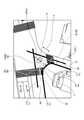
図2は、予測移動範囲40の一例の説明図である。図2に示すように、本実施の形態では、移動体10に搭載された情報処理装置20が、他車両30の予測移動範囲40を算出する(詳細後述)。 FIG. 2 is an explanatory diagram of an example of the predicted
なお、情報処理装置20は、移動体10に搭載された形態に限定されない。情報処理装置20は、静止物に搭載されていてもよい。静止物は、移動不可能な物や、地面に対して静止した状態の物である。静止物は、例えば、ガードレール、ポール、建物、道路、歩道、障害物、立体物、駐車車両、道路標識、などである。また、情報処理装置20は、クラウド上で処理を実行するクラウドサーバに搭載されていてもよい。 The
図1に戻り説明を続ける。センサ10Bは、外界センサであり、外界を検知した検知情報を取得する。本実施の形態では、センサ10Bは、他車両30を検知するためのセンサである。 The explanation will be continued by returning to FIG. The
センサ10Bは、例えば、撮影装置や、距離センサ(ミリ波レーダ、レーザセンサ)、などである。撮影装置は、撮影によって撮影画像データ(以下、撮影画像と称する)を得る。撮影画像データは、画素ごとに画素値を規定したデジタル画像データや、画素毎にセンサ10Bからの距離を規定したデプスマップなどである。レーザセンサは、例えば、水平面に対して平行に設置された二次元LIDAR(Laser Imaging Detection and Ranging)センサや、三次元LIDARセンサである。 The
出力部10Aは、各種の出力情報を出力する。出力部10Aは、例えば、出力情報を送信する通信機能、出力情報を表示する表示機能、出力情報を示す音を出力する音出力機能、などを備える。例えば、出力部10Aは、通信部10Dと、ディスプレイ10Eと、スピーカ10Fと、を含む。 The
通信部10Dは、各種データを他の装置と通信する。例えば、通信部10Dは、公知の通信回線を介して出力情報を送信する。また、例えば、通信部10Dは、公知の通信回線を介して、各種情報を外部装置から受信する。 The
ディスプレイ10Eは、出力情報を表示する。ディスプレイ10Eは、例えば、公知のLCD(liquid crystal display)や投影装置やライトなどである。スピーカ10Fは、出力情報を示す音を出力する。 The
駆動部10Hは、移動体10を駆動するデバイスである。駆動部10Hは、例えば、エンジン、モータ、車輪、などである。 The
駆動制御部10Gは、駆動部10Hを制御する。駆動部10Hは、駆動制御部10Gの制御によって駆動する。例えば、駆動制御部10Gは、情報処理装置20から出力された出力情報や、センサ10Bから得られた情報などに基づいて、周辺の状況を判断し、アクセル量、ブレーキ量、操舵角などの制御を行う。例えば、駆動制御部10Gは、障害物を避けて現在走行中の車線を保ち、かつ前方車両との車間距離を所定距離以上保つように車両の制御を行う。 The
次に、情報処理装置20の構成について詳細に説明する。図3は、情報処理装置20の構成の一例を示すブロック図である。 Next, the configuration of the
情報処理装置20は、例えば、専用または汎用コンピュータである。情報処理装置20は、処理部20Aと、記憶部20Bと、を備える。 The
処理部20A、記憶部20B、出力部10A、センサ10B、駆動制御部10G、および駆動部10Hは、バス20Zを介して接続されている。なお、記憶部20B、出力部10A(通信部10D、ディスプレイ10E、スピーカ10F)、およびセンサ10Bは、有線または無線で処理部20Aに接続すればよい。また、記憶部20B、出力部10A(通信部10D、ディスプレイ10E、スピーカ10F)、およびセンサ10Bのうちの少なくとも1つと、処理部20Aと、を、ネットワークを介して接続してもよい。 The
記憶部20Bは、各種データを記憶する。記憶部20Bは、例えば、RAM(Random Access Memory)、フラッシュメモリ等の半導体メモリ素子、ハードディスク、光ディスク等である。なお、記憶部20Bは、情報処理装置20の外部に設けられた記憶装置であってもよい。また、記憶部20Bは、記憶媒体であってもよい。具体的には、記憶媒体は、プログラムや各種情報を、LAN(Local Area Network)やインターネットなどを介してダウンロードして記憶または一時記憶したものであってもよい。また、記憶部20Bを、複数の記憶媒体から構成してもよい。また、記憶部20Bは、ネットワークを介して情報処理装置20に接続されたクラウドサーバに設けてもよい。 The
処理部20Aは、第1取得部20Cと、第2取得部20Dと、算出部20Eと、出力制御部20Fと、を備える。 The
上記各部(第1取得部20C、第2取得部20D、算出部20E、出力制御部20F)は、例えば、1または複数のプロセッサにより実現される。例えば上記各部は、CPU(Central Processing Unit)などのプロセッサにプログラムを実行させること、すなわちソフトウェアにより実現してもよい。上記各部は、専用のIC(Integrated Circuit)などのプロセッサ、すなわちハードウェアにより実現してもよい。上記各部は、ソフトウェアおよびハードウェアを併用して実現してもよい。複数のプロセッサを用いる場合、各プロセッサは、各部のうち1つを実現してもよいし、各部のうち2以上を実現してもよい。 Each of the above units (
第1取得部20Cは、移動体情報を取得する。移動体情報は、予測移動範囲40の算出対象の移動体である、他車両30を示す情報である。 The
具体的には、移動体情報は、他車両30の走行状態を示す情報である。詳細には、移動体情報は、他車両30の位置、角度、速度、加速度、角速度、および、角加速度の少なくとも1つを示す。 Specifically, the moving body information is information indicating the traveling state of the
例えば、第1取得部20Cは、センサ10Bの検知情報を用いて、公知の方法により、他車両30の移動体情報を算出することで、該移動体情報を取得する。 For example, the
なお、第1取得部20Cは、通信部10Dを介して外部装置や他車両30から、他車両30の移動体情報を受信することで、移動体情報を取得してもよい。 The
第2取得部20Dは、道路情報を取得する。道路情報は、他車両30の走行環境を示す情報である。すなわち、道路情報は、他車両30が走行中の道路および該道路の周辺の道路を示す情報である。 The
道路情報は、具体的には、参照経路、車線幅、参照経路の曲率、障害物の位置、および障害物の大きさの少なくとも1つを示す。 The road information specifically indicates at least one of a reference route, a lane width, a curvature of the reference route, an obstacle position, and an obstacle size.
図2を用いて説明する。参照経路32は、他車両30の走行中および走行予定の道路Rにおける、走行時の推奨ラインを示す。参照経路32は、道路Rの車線34ごとに予め定められている。車線34は、道路Rにおける、一縦列の車両の通行のために設けられた帯状の領域である。参照経路32は、例えば、車線34の幅方向の中央を通るように設けられている。 This will be described with reference to FIG. The
参照経路32は、例えば、複数の点の群によって表される(図2参照)。なお、参照経路32は、直線、スプライン曲線、またはクロソイド曲線などで表されてもよい。 The
車線幅Jは、車線34の幅を示す。具体的には、車線幅は、車線34における、車両の進行方向に対して直交する方向の長さを示す。参照経路32の曲率は、参照経路32における1または複数の曲線領域の各々の曲率を示す。障害物Hの位置および障害物Hの大きさは、絶対位置および絶対サイズであってもよいし、相対位置および相対サイズであってもよい。 The lane width J indicates the width of the
第2取得部20Dは、例えば、通信部10Dを介して外部装置から地図データを取得することで、他車両30の道路情報を取得する。この場合、地図データには、他車両30の走行中の道路Rおよび該道路Rの周辺の道路Rを含む道路情報が含まれるものとする。なお、第2取得部20Dは、他の方法を用いて、他車両30の道路情報を取得してもよい。例えば、第2取得部20Dは、センサ10Bの検知情報から道路情報を取得してもよい。また、第2取得部20Dは、外部装置から取得した地図データおよびセンサ10Bから取得した検知情報から、道路情報を取得してもよい。また、第2取得部20Dは、記憶部20Bに記憶された地図データから、道路情報を取得してもよい。 The
次に、算出部20Eについて説明する。 Next, the calculation unit 20E will be described.
算出部20Eは、移動体情報および道路情報に基づいて、他車両30の予測移動範囲40を算出する。 The calculation unit 20E calculates the predicted
予測移動範囲40とは、予測タイムの各々における、他車両30の予測される移動範囲を示す。予測タイムとは、現在以降(すなわち現在および未来)のタイミングを示す。 The predicted
予測移動範囲40の形状は、限定されない。例えば、予測移動範囲40の形状は、図2に示すように、楕円形状であってもよいし、矩形状、多角形状、円状、などであってもよい。 The shape of the predicted
本実施の形態では、算出部20Eは、移動体情報および道路情報に示される、参照経路32の曲率、走行可能範囲、および参照経路32の曲率に応じた角速度を用いて、他車両30の予測移動範囲40を算出する。 In the present embodiment, the calculation unit 20E predicts the
ここで、第1取得部20Cで取得した移動体情報、および第2取得部20Dで取得した道路情報に、参照経路32の曲率、走行可能範囲、および参照経路32の曲率に応じた角速度、の少なくとも1つが含まれない場合がある。 Here, the moving body information acquired by the
この場合、算出部20Eは、第1取得部20Cで取得した移動体情報、および第2取得部20Dで取得した道路情報に、参照経路32の曲率、走行可能範囲、および参照経路32の曲率に応じた角速度、の少なくとも1つを算出した算出結果に応じて、予測移動範囲40を算出する。 In this case, the calculation unit 20E applies the moving body information acquired by the
走行可能範囲とは、道路Rにおける、車両が走行可能な範囲を示す。図4は、カーブにおける走行可能範囲Pの一例を示す模式図である。 The travelable range indicates the range on which the vehicle can travel on the road R. FIG. 4 is a schematic view showing an example of the travelable range P in the curve.
走行可能範囲Pは、他車両30が走行することの可能な範囲であって、且つ、他車両30が道路Rの車線34に沿って走行するときに、参照経路32より外側や内側にずれて運転する可能性のある全ルートを包含する範囲である。 The travelable range P is a range in which the
参照経路32がカーブを示す場合、算出部20Eは、以下の方法で走行可能範囲Pを算出する。カーブを示すとは、参照経路32の曲率が閾値以上であることを示す。この閾値は、予め定めればよい。 When the
算出部20Eは、参照経路32におけるカーブを示す領域(以下、カーブ領域と称する場合がある)については、参照経路32に沿った道路Rの車線34と、カーブ領域と該カーブ領域外との境界Bと、に基づいて、走行可能範囲Pを算出する。 Regarding the region showing the curve in the reference route 32 (hereinafter, may be referred to as a curve region), the calculation unit 20E has the
詳細には、算出部20Eは、参照経路32に沿った道路Rの車線34の側縁を示すラインLを特定する。ラインLは、隣接する車線34の境界や、車線34と副道(歩道)との境界に形成されている。図4に示す例の場合、算出部20Eは、車線34のラインLとして、ラインL1、L2、L3、L4を特定する。 Specifically, the calculation unit 20E identifies a line L indicating a side edge of the
次に、算出部20Eは、カーブを示す領域であるカーブ領域内とカーブ領域外との境界Bとして、境界B1、B2を特定する。算出部20Eは、該カーブ領域の内側のラインL1と境界B1との交点と、該カーブ領域の内側のラインL3と境界B2との交点と、を結ぶ直線L’を特定する。 Next, the calculation unit 20E specifies the boundaries B1 and B2 as the boundary B between the inside of the curve area and the outside of the curve area, which is the area showing the curve. The calculation unit 20E specifies a straight line L'connecting the intersection of the line L1 inside the curve region and the boundary B1 and the intersection of the line L3 inside the curve region and the boundary B2.
そして、算出部20Eは、境界B1、直線L’、境界B2、該カーブ領域の外側のラインL4、および該カーブ領域の外側のラインL2によって囲まれた領域を、走行可能範囲Pとして算出する。 Then, the calculation unit 20E calculates the region surrounded by the boundary B1, the straight line L', the boundary B2, the line L4 outside the curve region, and the line L2 outside the curve region as the travelable range P.
一方、算出部20Eは、参照経路32における直線領域については、参照経路32に沿った道路Rの車線34と、直線領域とカーブ領域との境界Bと、に基づいて、走行可能範囲Pを算出する。 On the other hand, for the straight line region in the
図5は、直線領域における走行可能範囲Pの一例を示す模式図である。 FIG. 5 is a schematic view showing an example of the travelable range P in the straight line region.
詳細には、算出部20Eは、参照経路32に沿った道路Rの車線34の側縁を示すラインL(ラインL6、L7)を特定する。次に、算出部20Eは、直線領域とカーブ領域との境界B2を特定する。算出部20Eは、ラインL6と、ラインL7と、境界B2と、によって囲まれた領域を、走行可能範囲Pとして算出する。 Specifically, the calculation unit 20E identifies a line L (lines L6, L7) indicating a side edge of the
なお、算出部20Eによる走行可能範囲Pの算出方法は、上記方法に限定されない。例えば、算出部20Eは、複数の直線によって表される領域を走行可能範囲Pとして算出する形態に限定されず、円弧などの曲線によって表される領域を、走行可能範囲Pとして算出してもよい。 The method of calculating the travelable range P by the calculation unit 20E is not limited to the above method. For example, the calculation unit 20E is not limited to the form in which the region represented by a plurality of straight lines is calculated as the travelable range P, and the region represented by a curve such as an arc may be calculated as the travelable range P. ..
次に、参照経路32の曲率に応じた角速度について説明する。参照経路32の曲率に応じた角速度とは、該曲率の参照経路32に沿って他車両30が走行するときの角速度である。例えば、算出部20Eは、曲率と、該曲率の参照経路32に沿って移動体が走行するときの該移動体の角速度と、を予め記憶する。そして、算出部20Eは、第1取得部20Cで取得した参照経路32に示される曲率に対応する角速度を読取ることで、参照経路32の曲率に応じた角速度を算出すればよい。 Next, the angular velocity according to the curvature of the
また、算出部20Eは、参照経路32の曲率については、取得した参照経路32から、該参照経路32の曲率を公知の方法で算出すればよい。 Further, the calculation unit 20E may calculate the curvature of the
そして、算出部20Eは、移動体情報および道路情報を用いて、予測タイムごとに、他車両30の予測移動範囲40を算出する。 Then, the calculation unit 20E calculates the predicted
具体的には、算出部20Eは、以下の算出条件を満たすように、予測移動範囲40を算出する。 Specifically, the calculation unit 20E calculates the predicted
算出部20Eは、参照経路32の曲率が大きいほど、または、該曲率の領域の走行時の角速度が大きいほど、他車両30の進行方向に直交する幅方向の範囲が大きい、予測移動範囲40を算出する。また、算出部20Eは、参照経路32の曲率が小さいほど、または、該曲率の領域の走行時の角速度が小さいほど、幅方向の範囲の小さい、予測移動範囲40を算出する。なお、幅方向とは、本実施の形態では、他車両30の進行方向に直交する方向を示す。 The calculation unit 20E sets a predicted
また、算出部20Eは、走行可能範囲Pが大きいほど、他車両30の進行方向に直交する幅方向の範囲が大きい予測移動範囲40を算出する。また、算出部20Eは、走行可能範囲Pが小さいほど、該幅方向の範囲の小さい、予測移動範囲40を算出する。 Further, the calculation unit 20E calculates the predicted
例えば、上記算出条件を満たす予測移動範囲40を算出するために、算出部20Eは、参照経路32を走行するときの移動体情報の予測値と、予測値の分散値と、の予測結果を用いて、予測移動範囲40を算出する。予測値および分散値は、他車両30の、位置、角度、速度、加速度、角速度、および角加速度の少なくとも1つを示す。なお、角度については、予測タイムが現在のときの角度をゼロとし、予測タイムが現在以降はその差分の角度である。 For example, in order to calculate the predicted
具体的には、本実施の形態では、上記算出条件を満たす予測移動範囲40を算出するために、算出部20Eは、拡張カルマンフィルタ(Extended Kalman Filter:EKF)を用いて、予測移動範囲40を算出する。 Specifically, in the present embodiment, in order to calculate the predicted
拡張カルマンフィルタの観測値には、運転の理想的な状態を用いる。運転の理想的な状態とは、参照経路32に沿った運転、障害物Hを避けた運転、車線34の変更のための運転、カーブを曲がるための運転、停止、などの様々な運転のために必要な、理想的な速度、角速度、位置などを指す。 The ideal state of operation is used for the observed values of the extended Kalman filter. The ideal state of driving is for various driving such as driving along the
一方、拡張カルマンフィルタのシステムモデルには、物理モデルを用いる。具体的には、システムモデルには、加速度および角加速度がゼロに収束するモデルを用いる。これは、安定した運転に収束することを前提とするためである。 On the other hand, a physical model is used as the system model of the extended Kalman filter. Specifically, a model in which acceleration and angular acceleration converge to zero is used as the system model. This is because it is premised that the operation converges to stable operation.
なお、拡張カルマンフィルタのシステムモデルには、加速度および角加速度がゼロに収束するモデルに代えて、またはこれらのモデルと共に、等速モデル、等加速度モデル、等角速度モデル、等角加速度モデルなどを用いてもよい。 For the system model of the extended Kalman filter, a constant velocity model, a constant acceleration model, a constant angular velocity model, an equal angular acceleration model, etc. are used in place of the model in which the acceleration and the angular acceleration converge to zero, or together with these models. May be good.
以下、算出部20Eによる、拡張カルマンフィルタを用いた予測移動範囲40の算出について、具体的に説明する。 Hereinafter, the calculation of the predicted
まず、算出部20Eは、特定の予測タイムにおける移動体情報を、第1取得部20Cから受付ける。特定の予測タイムは、例えば、現在の時刻である。移動体情報は、上述したように、他車両30の位置、角度、速度、加速度、角速度、および角加速度の少なくとも1つを示す。例えば、算出部20Eは、特定の予測タイムにおける、他車両30の位置、角度、速度、加速度、角速度、および角加速度と、これらの変数に対する共分散と、を移動体情報として取得する。 First, the calculation unit 20E receives the moving body information at a specific predicted time from the
算出部20Eは、特定の予測タイムにおける移動体情報を、拡張カルマンフィルタの予測値の初期値として用いる。 The calculation unit 20E uses the mobile information at a specific predicted time as the initial value of the predicted value of the extended Kalman filter.
また、算出部20Eは、特定の予測タイムにおける他車両30の道路情報を、第2取得部20Dから取得する。すなわち、算出部20Eは、特定の予測タイムに他車両30が走行中の、道路Rおよび該道路Rの周辺の道路Rを示す道路情報を、第2取得部20Dから取得する。 Further, the calculation unit 20E acquires the road information of the
次に、算出部20Eは、予測タイムを1ステップ分進める。1ステップに相当する時間間隔は、予め定めればよい。 Next, the calculation unit 20E advances the predicted time by one step. The time interval corresponding to one step may be determined in advance.
そして、算出部20Eは、システムモデルとして用いる物理モデルを、1ステップ分進めた予測タイムの状態に変化させることで、システムモデル値を算出する。上述したように、システムモデルには、加速度および角加速度がゼロに収束するモデルを用いる。 Then, the calculation unit 20E calculates the system model value by changing the physical model used as the system model to the state of the predicted time advanced by one step. As described above, a model in which acceleration and angular acceleration converge to zero is used as the system model.
このため、算出部20Eは、移動体情報に示される他車両30の加速度および角速度を、ゼロに収束させる方向に、1ステップ分変化させる。そして、算出部20Eは、加速度および角加速度の1ステップ分変化させた後の値を、システムモデル値として用いる。そして、算出部20Eはシステムモデル値の各変数における共分散を求める。共分散は、物理モデルの状態方程式をテイラー展開して求めてもよいし、定数でもよい。 Therefore, the calculation unit 20E changes the acceleration and the angular velocity of the
次に、算出部20Eは、観測値を、運転の理想的な状態に向かって1ステップ分変化させることで、観測モデル値を算出する。上述したように、運転の理想的な状態とは、様々な運転のために必要な、理想的な速度、角速度、位置などを指す。 Next, the calculation unit 20E calculates the observation model value by changing the observation value by one step toward the ideal state of operation. As described above, the ideal state of driving refers to the ideal speed, angular velocity, position, etc. required for various driving.
このため、算出部20Eは、移動体情報および道路情報によって示される速度と角速度と位置を、移動体情報および道路情報を用いて、運転の理想的な状態に1ステップ分変化させる。そして、算出部20Eは、速度、角速度、および位置の1ステップ分変化させた後の値を、観測モデル値として用いる。 Therefore, the calculation unit 20E changes the speed, the angular velocity, and the position indicated by the moving body information and the road information by one step to the ideal state of driving by using the moving body information and the road information. Then, the calculation unit 20E uses the values after changing the velocity, the angular velocity, and the position by one step as the observation model values.
詳細には、例えば、算出部20Eは、移動体情報および道路情報によって示される速度と角速度と位置を、道路情報に示される、制限速度、カーブにおける加減速条件、停止条件、などの運転条件を用いて、特定の予測タイムから1ステップ分進めた予測タイムにおける、理想的な速度を算出する。 Specifically, for example, the calculation unit 20E determines the speed, angular velocity, and position indicated by the moving body information and the road information, and the operating conditions such as the speed limit, acceleration / deceleration condition in the curve, and stop condition indicated in the road information. It is used to calculate the ideal speed at the predicted time, which is one step ahead of the specific predicted time.
また、算出部20Eは、特定の予測タイムから1ステップ分進めた予測タイムにおいて、道路情報に示される参照経路32へ向かって1ステップ分収束させるため、道路情報に示される障害物Hを避けるため、などのために必要な角速度を、理想的な角速度として算出する。 Further, the calculation unit 20E converges one step toward the
また、算出部20Eは、特定の予測タイムから1ステップ分進めた予測タイムにおける、理想的な速度および角速度から、理想的な位置を算出する。なお、算出部20Eは、位置として、幅方向の位置を算出する。幅方向の位置は、参照経路32に沿って他車両30が進行するときの、他車両30の進行方向に対して直交する方向(幅方向)の座標値によって表される。 Further, the calculation unit 20E calculates the ideal position from the ideal speed and the angular velocity in the predicted time advanced by one step from the specific predicted time. The calculation unit 20E calculates a position in the width direction as a position. The position in the width direction is represented by the coordinate values in the direction (width direction) orthogonal to the traveling direction of the
このようにして、算出部20Eは、速度、角速度、および位置の各々について、予測タイムを1ステップ分変化させた後の値を、観測モデル値として算出する。 In this way, the calculation unit 20E calculates the value after changing the predicted time by one step for each of the velocity, the angular velocity, and the position as the observation model value.
次に、算出部20Eは、観測モデル値として算出した各要素(速度、角速度、位置)について、要素ごとに分散値を算出する。算出部20Eは、平均値が観測モデル値を示すように、分散値を算出する。分散値を算出する、とは、複数の分散値を算出することを意味する。すなわち、算出部20Eは、要素ごとに、観測モデル値が平均値となるように分散する、複数の分散値を算出する。 Next, the calculation unit 20E calculates the variance value for each element (velocity, angular velocity, position) calculated as the observation model value. The calculation unit 20E calculates the variance value so that the average value indicates the observation model value. To calculate the variance value means to calculate a plurality of variance values. That is, the calculation unit 20E calculates a plurality of dispersion values that are dispersed so that the observation model values become average values for each element.
具体的には、算出部20Eは、観測モデル値として算出した速度について、速度の分散値を算出する。速度の分散値は、過去に予測した速度と、特定の予測タイムにおける速度との、差に基づいて、公知の方法により算出すればよい。なお、算出部20Eは、一定値を、速度の分散値として算出してもよい。 Specifically, the calculation unit 20E calculates the velocity variance value for the velocity calculated as the observation model value. The speed variance value may be calculated by a known method based on the difference between the speed predicted in the past and the speed at a specific predicted time. The calculation unit 20E may calculate a constant value as a variance value of the velocity.
また、算出部20Eは、観測モデル値として算出した角速度について、角速度の分散値を算出する。 Further, the calculation unit 20E calculates the dispersion value of the angular velocity with respect to the angular velocity calculated as the observation model value.
算出部20Eは、他車両30の位置と参照経路32との差と、曲率を有する参照経路32に沿って走行するために必要な角速度と、に基づいて、予測値としての他車両30の角速度の分散値を算出する。 The calculation unit 20E determines the angular velocity of the
具体的には、算出部20Eは、角速度の分散値を、2種類の算出方法を用いて算出する。 Specifically, the calculation unit 20E calculates the dispersion value of the angular velocity by using two kinds of calculation methods.
一方の種類の算出方法は、他車両30の位置と参照経路32との差を考慮した算出方法である。この算出方法には、非特許文献1に記載された方法を用いればよい。すなわち、この場合、算出部20Eは、上記特定の予測タイムから1ステップ分進めた予測タイムにおける、他車両30の位置と参照経路32との位置の差と、該予測タイムにおける他車両30の傾きと、を考慮して算出する。他車両30の傾きとは、該予測タイムにおける、参照経路32に対する他車両30の進行方向の傾きを示す。この傾きは、道路情報および移動体情報から算出すればよい。 One type of calculation method is a calculation method that takes into consideration the difference between the position of the
他方の種類の算出方法は、角速度の大きさを考慮した算出方法である。この場合、算出部20Eは、下記式(1)を用いて、角速度の分散値を算出する。 The other type of calculation method is a calculation method that takes into consideration the magnitude of the angular velocity. In this case, the calculation unit 20E calculates the dispersion value of the angular velocity using the following formula (1).
covyr=Vconst(γ/γmax) 式(1)
γ=vcosθ/R 式(2)covyr = Vconst (γ / γmax ) Equation (1)
γ = vcosθ / R equation (2)
covyrは、角速度の分散値を示す。Vconstは、角速度分散の定数を示す。γは、上記式(2)で表される。Rは、参照経路32の曲率半径を示す。vは、観測モデル値として算出された速度を示し、θは、観測モデル値として算出された角度を示す。γmaxは、閾値以上の曲率のカーブの走行に必要な角速度の最大値である。covyr indicates the variance value of the angular velocity. Vconst indicates the constant of angular velocity variance. γ is represented by the above formula (2). R indicates the radius of curvature of the
算出部20Eが上記式(1)を用いて角速度の分散値を算出することで、角速度が大きいほど、大きい分散値が得られる。 When the calculation unit 20E calculates the dispersion value of the angular velocity using the above formula (1), the larger the angular velocity, the larger the dispersion value can be obtained.
本実施の形態では、算出部20Eは、上記2種類の算出方法の各々によって得られた分散値を合算した結果を、角速度の分散値として算出する。 In the present embodiment, the calculation unit 20E calculates the result of adding up the variance values obtained by each of the above two types of calculation methods as the variance value of the angular velocity.
また、算出部20Eは、観測モデル値として算出した位置について、位置の分散値を算出する。上述したように、本実施の形態では、位置は、他車両30の進行方向に対して直交する方向である幅方向における、位置である。 Further, the calculation unit 20E calculates the position variance value for the position calculated as the observation model value. As described above, in the present embodiment, the position is a position in the width direction which is a direction orthogonal to the traveling direction of the
本実施の形態では、算出部20Eは、第2取得部20Dで取得した道路情報に基づいて、位置の分散値を算出する。詳細には、算出部20Eは、走行可能範囲Pに基づいて、予測値としての他車両30の幅方向の位置の分散値を算出する。 In the present embodiment, the calculation unit 20E calculates the position dispersion value based on the road information acquired by the
具体的には、まず、算出部20Eは、走行可能範囲Pを算出する。上述したように、算出部20Eは、参照経路32をカーブ領域と直線領域に分類し、カーブ領域および直線領域の各々について、上述した方法で、走行可能範囲Pを算出する(図4、図5も参照)。 Specifically, first, the calculation unit 20E calculates the travelable range P. As described above, the calculation unit 20E classifies the
次に、算出部20Eは、走行可能範囲Pにおける、走行可能範囲Pを示す外枠と他車両30との、他車両30の幅方向における最大距離wを算出する。 Next, the calculation unit 20E calculates the maximum distance w in the width direction of the
図4に示す走行可能範囲Pを算出した場合、算出部20Eは、他車両30の幅方向(矢印Y方向)における、他車両30と走行可能範囲Pの外枠との距離(例えば、距離w1、距離w2)の内、最大の距離w1を、最大距離wとして算出する。 When the travelable range P shown in FIG. 4 is calculated, the calculation unit 20E determines the distance (for example, the distance w1) between the
図5に示す走行可能範囲Pを算出した場合、算出部20Eは、他車両30の幅方向(矢印Y方向)における、他車両30と走行可能範囲Pの外枠との距離の内、最大距離wを算出する。 When the travelable range P shown in FIG. 5 is calculated, the calculation unit 20E is the maximum distance among the distances between the
図3に戻り説明を続ける。算出部20Eは、下記式(3)を用いて、位置の分散値を算出する。 The explanation will be continued by returning to FIG. The calculation unit 20E calculates the variance value of the position using the following formula (3).
covy=(c・w/3)2 式(3)covy = (c ・ w / 3)2 formulas (3)
式(3)中、covyは、位置の分散値を示す。cは、定数である。wは、最大距離を示す。なお、式(3)において、cとwとの乗算値を“3”で除算する理由は、正規分布の99.7%は標準偏差の3倍の範囲に含まれる、という性質を考慮したためである。In the formula (3), covy indicates the variance value of the position. c is a constant. w indicates the maximum distance. In equation (3), the reason for dividing the multiplication value of c and w by "3" is because 99.7% of the normal distribution is included in the range of 3 times the standard deviation. be.
次に、算出部20Eは、上記算出した観測モデルの共分散とシステムモデルの共分散と、を用いて、カルマンゲインを算出する。カルマンゲインの算出には、公知の方法を用いればよい。具体的には、算出部20Eは、システムモデルを1ステップ分進めた共分散を、上記共分散と観測モデルの共分散を足し合わせた共分散で割った値を、カルマンゲインとして算出する。 Next, the calculation unit 20E calculates the Kalman gain by using the covariance of the observation model and the covariance of the system model calculated above. A known method may be used for calculating the Kalman gain. Specifically, the calculation unit 20E calculates the value obtained by dividing the covariance obtained by advancing the system model by one step by the covariance obtained by adding the covariance of the observation model and the covariance, as the Kalman gain.
次に、次に、算出部20Eは、算出したカルマンゲインと観測値を用いて、システムモデル値およびシステムモデル値の各要素の分散を補正することで、1ステップ分進めた予測タイムにおける、移動体情報の各要素の予測値と、予測値の分散値を算出する。 Next, the calculation unit 20E uses the calculated Kalman gain and the observed value to correct the variance of each element of the system model value and the system model value, thereby moving in the predicted time advanced by one step. The predicted value of each element of the body information and the variance value of the predicted value are calculated.
次に、算出部20Eは、最終的に算出した移動体情報の各要素の予測値と、予測値の分散値の内、位置の予測値と、位置の予測値の分散値、誤差楕円の信用区間を表すカイ二乗分布値と、を定めることで、誤差楕円の方程式を定める。このカイ二乗分布値は、予め定めればよい。 Next, the calculation unit 20E has the predicted value of each element of the finally calculated moving object information, the variance value of the predicted value, the predicted value of the position, the variance value of the predicted value of the position, and the confidence of the error ellipse. By defining the chi-square distribution value that represents the interval, the equation of the error ellipse is determined. This chi-square distribution value may be determined in advance.
そして、算出部20Eは、定めた誤差楕円の方程式によって表される楕円を、該予測タイムにおける予測移動範囲40として算出する。 Then, the calculation unit 20E calculates the ellipse represented by the equation of the determined error ellipse as the predicted
以上のようにして、本実施の形態では、算出部20Eは、拡張カルマンフィルタを用いて、予測タイムごとの予測移動範囲40を算出する。 As described above, in the present embodiment, the calculation unit 20E calculates the predicted
次に、出力制御部20Fについて説明する。出力制御部20Fは、出力情報を、出力部10Aおよび駆動制御部10Gの少なくとも一方へ出力する。 Next, the output control unit 20F will be described. The output control unit 20F outputs the output information to at least one of the
本実施の形態では、出力情報は、予測タイムごとの予測移動範囲40を示す情報を含む。 In the present embodiment, the output information includes information indicating the predicted
例えば、出力制御部20Fは、出力情報を、出力部10Aへ出力する。出力情報を受付けると、出力部10Aの通信部10Dは、外部装置などに、出力情報を送信する。また、例えば、出力部10Aのディスプレイ10Eは、出力情報を表示する。また、例えば、出力部10Aのスピーカ10Fが、出力情報に応じた音を出力する。出力情報に応じた音は、出力情報を示す音声であってもよいし、出力情報に応じた警告音であってもよい。 For example, the output control unit 20F outputs output information to the
また、例えば、出力制御部20Fは、出力情報を、駆動制御部10Gへ出力する。上述したように、駆動制御部10Gは、移動体10の駆動部10Hを制御する。出力情報を受付けた駆動制御部10Gは、出力情報や、センサ10Bから得られた情報などに基づいて、周辺の状況を判断し、アクセル量、ブレーキ量、操舵角などの制御を行う。例えば、駆動制御部10Gは、他車両30の予測移動範囲40に基づいて、他車両30を避けて現在走行中の車線を保ち、かつ前方車両や他車両30との車間距離を所定距離以上保つように車両の制御を行う。 Further, for example, the output control unit 20F outputs the output information to the
このような制御により、駆動制御部10Gは、移動体10の安全走行を実現することができる。 With such control, the
なお、出力制御部20Fは、出力情報を記憶部20Bへ記憶してもよい。また、出力制御部20Fは、出力情報を、他の処理機能部(例えば、衝突判定や運動予測などを行う機能)に対して出力してもよい。 The output control unit 20F may store the output information in the
次に、処理部20Aが実行する情報処理の手順の一例を説明する。図6は、処理部20Aが実行する情報処理の手順の一例を示す、フローチャートである。 Next, an example of the information processing procedure executed by the
まず、第1取得部20Cが、予測タイムTにおける移動体情報を取得する(ステップS100)。予測タイムTは、上述した特定の予測タイムである。次に、算出部20Eが、ステップS100で取得した、予測タイムTの移動体情報を、拡張カルマンフィルタの予測値の初期値として設定する(ステップS102)。 First, the
次に、第2取得部20Dが、予測タイムTにおける道路情報を取得する(ステップS104)。 Next, the
次に、算出部20Eは、予測タイムTを1ステップ分進める(ステップS106)。 Next, the calculation unit 20E advances the predicted time T by one step (step S106).
次に、算出部20Eは、システムモデル値を算出する(ステップS108)。ステップS108では、算出部20Eは、予測タイムTを1ステップ分進める前の移動体情報に示される他車両30の加速度および角速度を、ゼロに収束させる方向に1ステップ分変化させることで、システムモデル値を算出する。そして、算出部20Eはシステムモデル値の各変数における共分散を求める。 Next, the calculation unit 20E calculates the system model value (step S108). In step S108, the calculation unit 20E changes the acceleration and angular velocity of the
次に、算出部20Eは、観測モデル値を算出する(ステップS110)。ステップS110では、算出部20Eは、予測タイムTを1ステップ分進める前の移動体情報および道路情報によって示される速度、角速度、および位置を、運転の理想的な状態に向かって1ステップ分変化させることで、観測モデル値を算出する。 Next, the calculation unit 20E calculates the observation model value (step S110). In step S110, the calculation unit 20E changes the speed, angular velocity, and position indicated by the moving object information and the road information before advancing the predicted time T by one step toward the ideal state of driving by one step. By doing so, the observation model value is calculated.
次に、算出部20Eは、ステップS110で観測モデル値として算出した速度について、速度の分散値を算出する(ステップS112)。 Next, the calculation unit 20E calculates the velocity variance value for the velocity calculated as the observation model value in step S110 (step S112).
次に、算出部20Eは、ステップS110で観測モデル値として算出した角速度について、角速度の分散値を算出する(ステップS114)。 Next, the calculation unit 20E calculates the dispersion value of the angular velocity with respect to the angular velocity calculated as the observation model value in step S110 (step S114).
次に、算出部20Eは、ステップS104で取得した道路情報に示される参照経路32について、上述した方法で、走行可能範囲Pを算出する(ステップS116)。次に、算出部20Eは、走行可能範囲Pにおける、走行可能範囲Pを示す外枠と他車両30との、他車両30の幅方向における最大距離wを算出する(ステップS118)。そして、算出部20EはステップS118で算出した最大距離wと上記式(3)とを用いて、位置の分散値を算出する(ステップS120)。 Next, the calculation unit 20E calculates the travelable range P for the
次に、算出部20Eは、ステップS108で算出したシステムモデルの共分散とステップS112〜ステップ120で算出した観測モデルの共分散と、を用いて、カルマンゲインを算出する(ステップS122)。 Next, the calculation unit 20E calculates the Kalman gain using the covariance of the system model calculated in step S108 and the covariance of the observation model calculated in steps S112 to 120 (step S122).
次に、算出部20Eは、ステップS106で1ステップ分進めた予測タイムTにおける、移動体情報の各要素の予測値と、予測値の分散値を算出する(ステップS124)ステップS124では、算出部20Eは、ステップS122で算出したカルマンゲインと、ステップS110で算出した観測モデル値と、ステップS112〜S120で算出した観測モデル値の各要素の分散と、を用いて、S108で算出したシステムモデル値およびシステムモデル値の各要素の分散を補正することで、予測値と予測値の分散を算出する。 Next, the calculation unit 20E calculates the predicted value of each element of the moving body information and the dispersion value of the predicted value in the predicted time T advanced by one step in step S106 (step S124). In step S124, the calculation unit 20E calculates. 20E is a system model value calculated in S108 using the Kalman gain calculated in step S122, the observation model value calculated in step S110, and the dispersion of each element of the observation model value calculated in steps S112 to S120. And by correcting the variance of each element of the system model value, the variance of the predicted value and the predicted value is calculated.
次に、算出部20Eは、ステップS106で1ステップ分進めた予測タイムTにおける、予測移動範囲40を算出する(ステップS126)。ステップS126では、算出部20Eは、ステップS124で算出した、移動体情報の各要素の予測値と、予測値の分散値の内、位置の予測値の分散値と、誤差楕円の信用区間を表すカイ二乗分布値と、によって定められる誤差楕円の方程式によって表される楕円を、予測移動範囲40として算出する。 Next, the calculation unit 20E calculates the predicted
次に、出力制御部20Fは、ステップS126で算出された予測移動範囲40と、該予測移動範囲40の予測タイムと、を含む出力情報を、出力部10Aおよび駆動制御部10Gの少なくとも一方へ出力する(ステップS128)。 Next, the output control unit 20F outputs output information including the predicted
このため、例えば、駆動制御部10Gは、予測移動範囲40に基づいて、情報処理装置20の搭載された移動体10の駆動部10Hを制御する。例えば、駆動制御部10Gは、他車両30や障害物を避けて現在走行中の車線を保ち、かつ前方車両や他車両30との車間距離を所定距離以上保つように車両の制御を行う。 Therefore, for example, the
次に、算出部20Eは、予測を終了するか否かを判断する(ステップS130)。例えば、算出部20Eは、予め定めた予測ステップ数、予測を実行したか否を判別することで、ステップS130の判断を行う。ステップS130で否定判断すると(ステップS130:No)、上記ステップS106へ進む。一方、ステップS130で肯定判断すると(ステップS130:Yes)、本ルーチンを終了する。 Next, the calculation unit 20E determines whether or not to end the prediction (step S130). For example, the calculation unit 20E determines the step S130 by determining the number of prediction steps determined in advance and whether or not the prediction has been executed. If a negative determination is made in step S130 (step S130: No), the process proceeds to step S106. On the other hand, if an affirmative judgment is made in step S130 (step S130: Yes), this routine ends.
このように、本実施の形態では、算出部20Eは、予測タイムTごとに、予測移動範囲40を算出する。 As described above, in the present embodiment, the calculation unit 20E calculates the predicted
このため、例えば、図2に示すように、算出部20Eは、予測タイムTごとの予測移動範囲40を算出する。例えば、他車両30が予測タイムTにおいて他車両30Aの位置にいると仮定する。この場合、情報処理装置20の算出部20Eは、1または複数ステップ進めた予測タイムT(例えば、他車両30Bの位置、および他車両30Cの位置)の各々における、他車両30の予測移動範囲40(予測移動範囲40B、予測移動範囲40C)を算出する。 Therefore, for example, as shown in FIG. 2, the calculation unit 20E calculates the predicted
すなわち、算出部20Eは、予測タイムTに他車両30が到達すると仮定される位置を中心とした楕円状の予測移動範囲40を、予測タイムTごとに算出する。なお、上述したように、予測移動範囲40の形状は、楕円状に限定されない。 That is, the calculation unit 20E calculates an elliptical predicted
図2に示すように、上記処理を行うことで、算出部20Eは、交差点などのカーブ領域では幅方向の大きさの大きい予測移動範囲40Bを算出し、直線領域では幅方向の大きさの小さい予測移動範囲40Cを算出する。 As shown in FIG. 2, by performing the above processing, the calculation unit 20E calculates a predicted
以上説明したように、本実施の形態の情報処理装置20は、第1取得部20Cと、第2取得部20Dと、を備える。第1取得部20Cは、移動体(他車両30)に関する移動体情報を取得する。第2取得部20Dは、道路情報を取得する。算出部20Eは、移動体情報および道路情報に基づいて、移動体(他車両30)の予測移動範囲40を算出する。 As described above, the
このように、本実施の形態の情報処理装置20は、移動体情報のみではなく、道路情報と移動体情報を用いて、他車両30の予測移動範囲40を算出する。このため、本実施の形態の情報処理装置20では、移動体情報および道路情報に応じた適切な予測移動範囲40を算出することができる。 As described above, the
例えば、上述したように、本実施の形態の情報処理装置20は、交差点などのカーブ領域では幅方向の大きさの大きい予測移動範囲40Bを算出し、直線領域では幅方向の大きさの小さい予測移動範囲40Cを算出することができる。 For example, as described above, the
従って、本実施の形態の情報処理装置20は、予測移動範囲40を精度良く算出することができる。 Therefore, the
また、本実施の形態の情報処理装置20では、駆動制御部10Gが、予測移動範囲40に応じて駆動部10Hを駆動する。このため、本実施の形態の情報処理装置20では、上記効果に加えて、他車両30との衝突を回避可能な有用な予測移動範囲40を提供することができる。また、本実施の形態の情報処理装置20では、過剰に広い予測移動範囲40を算出することを抑制することができるため、上記効果に加えて、不要な警告などを移動体10に与える事を抑制することができる。 Further, in the
(変形例1)
なお、上記実施の形態では、算出部20Eは、拡張カルマンフィルタを用いて予測移動範囲40を算出する形態を一例として説明した。しかし、算出部20Eは、上記実施の形態で説明した算出条件を満たすように、予測移動範囲40を算出すればよく、拡張カルマンフィルタに代えて、公知のフィルタを用いてもよい。(Modification example 1)
In the above embodiment, the calculation unit 20E has described a mode in which the predicted
例えば、算出部20Eは、上記算出条件を満たす予測移動範囲40を算出するために、拡張カルマンフィルタに代えて、Kalman Filter、Particle Filter、Unscented Kalman Filterなどを用いてもよい。 For example, the calculation unit 20E may use a Kalman Filter, a Particle Filter, an Associated Kalman Filter, or the like instead of the extended Kalman filter in order to calculate the predicted
Kalman Filterを用いる場合、変数を、線形で扱う必要がある。このため、変数の数は、拡張カルマンフィルタを用いる場合に比べて制限される。しかし、算出部20Eは、上記実施の形態と同様にして、道路情報および移動体情報に基づいて、Kalman Filterを用いることで、予測値の分散値を算出し、予測移動範囲40を算出することができる。 When using Kalman Filter, variables need to be treated linearly. Therefore, the number of variables is limited as compared with the case of using the extended Kalman filter. However, the calculation unit 20E calculates the variance value of the predicted value and calculates the predicted moving
また、Particle Filterを用いる場合には、観測モデルの代わりに尤度関数を設計する必要がある。しかし、算出部20Eは、上記実施の形態で算出した観測モデル値と観測モデル値の各要素の分散値を、尤度計算に用いることで、上記実施の形態と同様にして予測移動範囲40を算出することができる。 In addition, when using a Particle Filter, it is necessary to design a likelihood function instead of an observation model. However, the calculation unit 20E uses the variance value of each element of the observation model value and the observation model value calculated in the above embodiment for the likelihood calculation to obtain the predicted
Unscented Kalman Filterを用いる場合は、拡張カルマンフィルタと同様に、観測モデル値とシステムモデル値を定義する必要がある。このため、この場合についても、算出部20Eは、上記実施の形態で用いた予測値の分散値の算出と同様の計算方法を用いて、予測移動範囲40を算出することができる。 When using the Associated Kalman Filter, it is necessary to define the observation model value and the system model value as in the extended Kalman filter. Therefore, also in this case, the calculation unit 20E can calculate the predicted
(変形例2)
なお、道路R上に障害物Hが存在する場合がある。(Modification 2)
An obstacle H may exist on the road R.
この場合、算出部20Eは、障害物情報に更に基づいて、予測移動範囲40を算出する。 In this case, the calculation unit 20E further calculates the predicted
障害物情報は、障害物Hを示す情報である。障害物情報は、例えば、障害物Hの位置、および障害物Hの大きさの少なくとも一方を示す。 The obstacle information is information indicating the obstacle H. The obstacle information indicates, for example, the position of the obstacle H and at least one of the sizes of the obstacle H.
道路情報が、障害物Hの位置および障害物Hの大きさの少なくとも一方を含む場合、算出部20Eは、道路情報から障害物情報を特定する。そして、算出部20Eは、障害物情報によって示される障害物Hの位置や大きさに基づいて、該障害物Hを避けるように、走行可能範囲Pおよび最大距離wを設定する。 When the road information includes at least one of the position of the obstacle H and the size of the obstacle H, the calculation unit 20E identifies the obstacle information from the road information. Then, the calculation unit 20E sets the travelable range P and the maximum distance w so as to avoid the obstacle H based on the position and size of the obstacle H indicated by the obstacle information.
図7を用いて説明する。図7は、走行可能範囲Pの一例を示す模式図である。算出部20Eは、上記実施の形態で説明した方法と同様にして走行可能範囲Pを算出する。但し、算出部20Eは、上記実施の形態と同様にして算出した走行可能範囲Pにおける、障害物Hとの重複領域を除外した領域を、走行可能範囲Pとして算出する。 This will be described with reference to FIG. FIG. 7 is a schematic view showing an example of the travelable range P. The calculation unit 20E calculates the travelable range P in the same manner as the method described in the above embodiment. However, the calculation unit 20E calculates as the travelable range P the region excluding the overlapping region with the obstacle H in the travelable range P calculated in the same manner as in the above embodiment.
そして、算出部20Eは、第1の実施の形態と同様に、走行可能範囲Pにおける、走行可能範囲Pを示す外枠と他車両30との、他車両30の幅方向における最大距離wを算出する。なお、上述したように、本変形例では、算出部20Eは、上記実施の形態と同様にして算出した走行可能範囲Pにおける、障害物Hとの重複領域を除外した領域を、走行可能範囲Pとして算出する。このため、本変形例では、算出部20Eは、上記実施の形態と同様にして算出した走行可能範囲Pにおける、障害物Hを除外した領域について、他車両30と該領域の外枠との幅方向の最大距離wを算出する。 Then, the calculation unit 20E calculates the maximum distance w in the width direction of the
そして、算出部20Eは、算出した走行可能範囲Pと最大距離wを用いて、上記実施の形態と同様にして位置の分散値、カルマンゲインを算出することで、予測移動範囲40を算出すればよい。 Then, the calculation unit 20E calculates the predicted
(ハードウェア構成)
次に、上記実施の形態の情報処理装置20のハードウェア構成の一例を説明する。図8は、上記実施の形態の情報処理装置20のハードウェア構成図の一例を示す図である。(Hardware configuration)
Next, an example of the hardware configuration of the
上記実施の形態の情報処理装置20は、CPU(Central Processing Unit)86などの制御装置と、ROM(Read Only Memory)88やRAM(Random Access Memory)90やHDD(ハードディスクドライブ)92などの記憶装置と、各種機器とのインターフェースであるI/F部82と、出力情報などの各種情報を出力する出力部80と、ユーザによる操作を受付ける入力部94と、各部を接続するバス96とを備えており、通常のコンピュータを利用したハードウェア構成となっている。 The
上記実施の形態の情報処理装置20では、CPU86が、ROM88からプログラムをRAM90上に読み出して実行することにより、上記各機能がコンピュータ上で実現される。 In the
なお、上記実施の形態の情報処理装置20で実行される上記各処理を実行するためのプログラムは、HDD92に記憶されていてもよい。また、上記実施の形態の情報処理装置20で実行される上記各処理を実行するためのプログラムは、ROM88に予め組み込まれて提供されていてもよい。 The program for executing each of the above processes executed by the
また、上記実施の形態の情報処理装置20で実行される上記処理を実行するためのプログラムは、インストール可能な形式または実行可能な形式のファイルでCD−ROM、CD−R、メモリカード、DVD(Digital Versatile Disk)、フレキシブルディスク(FD)等のコンピュータで読み取り可能な記憶媒体に記憶されてコンピュータプログラムプロダクトとして提供されるようにしてもよい。また、上記実施の形態の情報処理装置20で実行される上記処理を実行するためのプログラムを、インターネットなどのネットワークに接続されたコンピュータ上に格納し、ネットワーク経由でダウンロードさせることにより提供するようにしてもよい。また、上記実施の形態の情報処理装置20で実行される上記処理を実行するためのプログラムを、インターネットなどのネットワーク経由で提供または配布するようにしてもよい。 Further, the program for executing the above processing executed by the
なお、上記には、本発明の実施の形態を説明したが、上記実施の形態は、例として提示したものであり、発明の範囲を限定することは意図していない。この新規な実施の形態は、その他の様々な形態で実施されることが可能であり、発明の要旨を逸脱しない範囲で、種々の省略、置き換え、変更を行うことができる。この実施の形態やその変形は、発明の範囲や要旨に含まれるとともに、特許請求の範囲に記載された発明とその均等の範囲に含まれる。 Although the embodiment of the present invention has been described above, the embodiment is presented as an example and is not intended to limit the scope of the invention. This novel embodiment can be implemented in various other forms, and various omissions, replacements, and changes can be made without departing from the gist of the invention. This embodiment and its modifications are included in the scope and gist of the invention, and are also included in the scope of the invention described in the claims and the equivalent scope thereof.
10 移動体
10G 駆動制御部
10H 駆動部
20 情報処理装置
20C 第1取得部
20D 第2取得部
20E 算出部
30 他車両10
Claims (15)
Translated fromJapanese道路情報を取得する第2取得部と、
前記移動体情報および前記道路情報に基づいて、前記移動体の予測移動範囲を算出する算出部と、
を備え、
前記算出部は、
前記移動体情報と前記道路情報から、参照経路の曲率、および参照経路の曲率に応じた角速度、の少なくとも一つを算出した算出結果に応じて、前記予測移動範囲を算出し、
前記参照経路を走行するときの前記移動体情報の予測値と、前記予測値の分散値と、の予測結果を用いて、前記予測移動範囲を算出する、
情報処理装置。The first acquisition unit that acquires mobile information about mobiles,
The second acquisition department that acquires road information and
A calculation unit that calculates the predicted movement range of the moving body based on the moving body information and the road information.
With
The calculation unit
The moving body information from said road information, the curvature of the reference path, and the angular velocity corresponding to the curvature of the reference path, according to at least one calculates the calculation result ofcalculating the predicted movement range,
The predicted movement range is calculated by using the prediction result of the predicted value of the moving body information when traveling on the reference route and the dispersion value of the predicted value.
Information processing device.
前記移動体の、位置、角度、速度、加速度、角速度、および角加速度の少なくとも1つを示す、
請求項1に記載の情報処理装置。The predicted value and the variance value are
Indicates at least one of the position, angle, velocity, acceleration, angular velocity, and angular acceleration of the moving body.
The information processing device according to claim1.
前記移動体の位置と前記参照経路との差と、曲率を有する参照経路に沿って走行するために必要な角速度と、に基づいて前記予測値としての前記移動体の角速度の、前記分散値を算出する、
請求項1または請求項2に記載の情報処理装置。The calculation unit
Based on the difference between the position of the moving body and the reference path, the angular velocity required to travel along the reference path having a curvature, and the dispersion value of the angular velocity of the moving body as the predicted value. calculate,
The information processing device according to claim1or 2.
走行可能範囲に基づいて、前記予測値としての前記移動体の幅方向の位置の、前記分散値を算出する、
請求項1〜請求項3の何れか1項に記載の情報処理装置。The calculation unit
Based on the travelable range, the dispersion value of the position in the width direction of the moving body as the predicted value is calculated.
The information processing apparatus according to any one of claims1 to3.
障害物を示す障害物情報に更に基づいて、前記予測移動範囲を算出する、
請求項1に記載の情報処理装置。The calculation unit
The predicted movement range is calculated based on the obstacle information indicating the obstacle.
The information processing device according to claim 1.
前記参照経路の曲率が大きいほどまたは該曲率の領域の走行時の角速度が大きいほど、前記移動体の進行方向に直交する幅方向の範囲が大きく、
該参照経路の曲率が小さいほどまたは該曲率の領域の走行時の角速度が小さいほど前記幅方向の範囲の小さい、
前記予測移動範囲を算出する、
請求項1〜請求項5の何れか1項に記載の情報処理装置。The calculation unit
The larger the curvature of the reference path or the larger the angular velocity during traveling in the region of the curvature, the larger the range in the width direction orthogonal to the traveling direction of the moving body.
The smaller the curvature of the reference path or the smaller the angular velocity during traveling in the region of the curvature, the smaller the range in the width direction.
Calculate the predicted movement range,
The information processing apparatus according toany one of claims 1to5.
走行可能範囲が大きいほど、前記移動体の進行方向に直交する幅方向の範囲が大きく、
前記走行可能範囲が小さいほど、前記幅方向の範囲の小さい、
前記予測移動範囲を算出する、
請求項1〜請求項6の何れか1項に記載の情報処理装置。The calculation unit
The larger the travelable range, the larger the range in the width direction orthogonal to the traveling direction of the moving body.
The smaller the travelable range, the smaller the range in the width direction.
Calculate the predicted movement range,
The information processing device according to any one of claims 1 to6.
前記参照経路の曲率が閾値以上のカーブ領域について、該参照経路に沿った道路の車線と、該カーブ領域と該カーブ領域外との境界と、に応じて走行可能範囲を算出する、
請求項1〜請求項7の何れか1項に記載の情報処理装置。The calculation unit
For a curve region in which the curvature of the reference route is equal to or greater than a threshold value, the travelable range is calculated according to the lane of the road along the reference route and the boundary between the curve region and the outside of the curve region.
The information processing device according to any one of claims 1 to7.
請求項1〜請求項8の何れか1項に記載の情報処理装置。The moving body information indicates a traveling state of the moving body.
The information processing device according to any one of claims 1 to8.
前記移動体の位置、角度、速度、加速度、角速度、および角加速度の少なくとも1つを示す、
請求項1〜請求項9の何れか1項に記載の情報処理装置。The mobile information is
Indicates at least one of the position, angle, velocity, acceleration, angular velocity, and angular acceleration of the moving body.
The information processing device according to any one of claims 1 to9.
請求項1〜請求項10の何れか1項に記載の情報処理装置。The road information indicates the traveling environment of the moving body.
The information processing apparatus according to any one of claims 1 to 10.
前記参照経路、車線幅、前記参照経路の曲率、障害物の位置、および障害物の大きさ、の少なくとも1つを示す、
請求項1〜請求項10の何れか1項に記載の情報処理装置。The road information is
Indicates at least one of the reference path, the lane width, the curvature of the reference path, the position of the obstacle, and the size of the obstacle.
The information processing apparatus according to any one of claims 1 to 10.
を備える、請求項1〜請求項12の何れか1項に記載の情報処理装置。A drive control unit that controls a drive unit of a mobile body on which the information processing device is mounted based on the predicted movement range.
The provided information processing apparatus according to any one of claims 1 to 12.
道路情報を取得する第2取得ステップと、
前記移動体情報および前記道路情報に基づいて、前記移動体の予測移動範囲を算出する算出ステップと、
を含み、
前記算出ステップは、
前記移動体情報と前記道路情報から、参照経路の曲率、および参照経路の曲率に応じた角速度、の少なくとも一つを算出した算出結果に応じて、前記予測移動範囲を算出し、
前記参照経路を走行するときの前記移動体情報の予測値と、前記予測値の分散値と、の予測結果を用いて、前記予測移動範囲を算出する、
情報処理方法。The first acquisition step to acquire the mobile information about the mobile,
The second acquisition step to acquire road information and
A calculation step for calculating the predicted movement range of the moving body based on the moving body information and the road information, and
Including
The calculation step is
The moving body information from said road information, the curvature of the reference path, and the angular velocity corresponding to the curvature of the reference path, according to at least one calculates the calculation result ofcalculating the predicted movement range,
The predicted movement range is calculated by using the prediction result of the predicted value of the moving body information when traveling on the reference route and the dispersion value of the predicted value.
Information processing method.
道路情報を取得する第2取得ステップと、
前記移動体情報および前記道路情報に基づいて、前記移動体の予測移動範囲を算出する算出ステップと、
をコンピュータに実行させるためのプログラムであって、
前記算出ステップは、
前記移動体情報と前記道路情報から、参照経路の曲率、および参照経路の曲率に応じた角速度、の少なくとも一つを算出した算出結果に応じて、前記予測移動範囲を算出し、
前記参照経路を走行するときの前記移動体情報の予測値と、前記予測値の分散値と、の予測結果を用いて、前記予測移動範囲を算出する、
プログラム。The first acquisition step to acquire the mobile information about the mobile,
The second acquisition step to acquire road information and
A calculation step for calculating the predicted movement range of the moving body based on the moving body information and the road information, and
Is a program that allows a computer to execute
The calculation step is
The moving body information from said road information, the curvature of the reference path, and the angular velocity corresponding to the curvature of the reference path, according to at least one calculates the calculation result ofcalculating the predicted movement range,
The predicted movement range is calculated by using the prediction result of the predicted value of the moving body information when traveling on the reference route and the dispersion value of the predicted value.
program.
Priority Applications (3)
| Application Number | Priority Date | Filing Date | Title |
|---|---|---|---|
| JP2017202802AJP6937218B2 (en) | 2017-10-19 | 2017-10-19 | Information processing equipment, information processing methods, and programs |
| US15/911,198US11267463B2 (en) | 2017-10-19 | 2018-03-05 | Information processing device, information processing method, and computer program product |
| JP2021112388AJP7346499B2 (en) | 2017-10-19 | 2021-07-06 | Information processing device, information processing method, and program |
Applications Claiming Priority (1)
| Application Number | Priority Date | Filing Date | Title |
|---|---|---|---|
| JP2017202802AJP6937218B2 (en) | 2017-10-19 | 2017-10-19 | Information processing equipment, information processing methods, and programs |
Related Child Applications (1)
| Application Number | Title | Priority Date | Filing Date |
|---|---|---|---|
| JP2021112388ADivisionJP7346499B2 (en) | 2017-10-19 | 2021-07-06 | Information processing device, information processing method, and program |
Publications (2)
| Publication Number | Publication Date |
|---|---|
| JP2019075055A JP2019075055A (en) | 2019-05-16 |
| JP6937218B2true JP6937218B2 (en) | 2021-09-22 |
Family
ID=66170448
Family Applications (2)
| Application Number | Title | Priority Date | Filing Date |
|---|---|---|---|
| JP2017202802AActiveJP6937218B2 (en) | 2017-10-19 | 2017-10-19 | Information processing equipment, information processing methods, and programs |
| JP2021112388AActiveJP7346499B2 (en) | 2017-10-19 | 2021-07-06 | Information processing device, information processing method, and program |
Family Applications After (1)
| Application Number | Title | Priority Date | Filing Date |
|---|---|---|---|
| JP2021112388AActiveJP7346499B2 (en) | 2017-10-19 | 2021-07-06 | Information processing device, information processing method, and program |
Country Status (2)
| Country | Link |
|---|---|
| US (1) | US11267463B2 (en) |
| JP (2) | JP6937218B2 (en) |
Families Citing this family (13)
| Publication number | Priority date | Publication date | Assignee | Title |
|---|---|---|---|---|
| US12038765B2 (en)* | 2016-08-02 | 2024-07-16 | Transportation Ip Holdings, Llc | Vehicle control system and method |
| KR102463720B1 (en)* | 2017-12-18 | 2022-11-07 | 현대자동차주식회사 | System and Method for creating driving route of vehicle |
| CN108919805B (en)* | 2018-07-04 | 2021-09-28 | 江苏大块头智驾科技有限公司 | Vehicle unmanned auxiliary system |
| EP3748604B1 (en) | 2019-06-04 | 2023-03-01 | Hitachi Astemo, Ltd. | Vehicle travelling control apparatus, vehicle travelling control method and computer program product |
| JP7098580B2 (en)* | 2019-07-05 | 2022-07-11 | 株式会社東芝 | Predictors, predictors, programs and vehicle control systems |
| JP7328863B2 (en)* | 2019-10-11 | 2023-08-17 | 株式会社デンソー | Control device |
| CN110658827B (en)* | 2019-10-25 | 2020-06-23 | 嘉应学院 | Transport vehicle automatic guiding system and method based on Internet of things |
| CN110979318B (en)* | 2019-11-20 | 2021-06-04 | 苏州智加科技有限公司 | Lane information acquisition method and device, automatic driving vehicle and storage medium |
| DE102020200183A1 (en) | 2020-01-09 | 2021-07-15 | Continental Automotive Gmbh | Method for creating a probabilistic free space map with static and dynamic objects |
| CN111276009B (en)* | 2020-02-28 | 2021-09-28 | 长安大学 | System and method for reminding front and rear vehicles of out-of-control truck on long downhill section |
| US20220289195A1 (en)* | 2021-03-15 | 2022-09-15 | GM Global Technology Operations LLC | Probabilistic adaptive risk horizon for event avoidance and mitigation in automated driving |
| CN115303268B (en)* | 2022-08-31 | 2024-08-13 | 中国第一汽车股份有限公司 | Information processing method, device and storage medium for vehicle |
| US12399577B2 (en)* | 2024-01-05 | 2025-08-26 | Google Llc | Stylus three-dimensional trajectory prediction |
Family Cites Families (23)
| Publication number | Priority date | Publication date | Assignee | Title |
|---|---|---|---|---|
| JP5019340B2 (en)* | 2000-08-31 | 2012-09-05 | 村田機械株式会社 | Track structure of overhead transport vehicle |
| JP4637690B2 (en)* | 2005-08-31 | 2011-02-23 | 三菱電機株式会社 | Road shape recognition device |
| JP4689546B2 (en)* | 2006-07-06 | 2011-05-25 | 本田技研工業株式会社 | Vehicle object detection device |
| JP5104398B2 (en)* | 2008-02-27 | 2012-12-19 | 日産自動車株式会社 | Driving support device |
| JP4853525B2 (en)* | 2009-02-09 | 2012-01-11 | トヨタ自動車株式会社 | Moving region prediction device |
| JP5419784B2 (en)* | 2010-04-06 | 2014-02-19 | 三菱電機株式会社 | Prediction device, prediction system, computer program, and prediction method |
| JP5809785B2 (en)* | 2010-07-30 | 2015-11-11 | 日立オートモティブシステムズ株式会社 | Vehicle external recognition device and light distribution control system using the same |
| JP2012164159A (en)* | 2011-02-07 | 2012-08-30 | Toyota Motor Corp | Risk determination device, risk determination program, and risk determination method |
| JP5673597B2 (en)* | 2011-11-18 | 2015-02-18 | 株式会社デンソー | Vehicle behavior control device |
| TWI625260B (en)* | 2012-11-20 | 2018-06-01 | Method and system for detecting lane curvature by using body signal | |
| JP5878491B2 (en)* | 2013-03-27 | 2016-03-08 | 株式会社日本自動車部品総合研究所 | Driving assistance device |
| US9254846B2 (en)* | 2013-05-03 | 2016-02-09 | Google Inc. | Predictive reasoning for controlling speed of a vehicle |
| JP2014241036A (en)* | 2013-06-11 | 2014-12-25 | 三菱電機株式会社 | Vehicle driving assist system |
| EP3514032B1 (en)* | 2013-12-04 | 2024-02-07 | Mobileye Vision Technologies Ltd. | Adjusting velocity of a vehicle for a curve |
| WO2015155833A1 (en)* | 2014-04-08 | 2015-10-15 | 三菱電機株式会社 | Collision prevention device |
| JP2015219830A (en)* | 2014-05-20 | 2015-12-07 | トヨタ自動車株式会社 | Driving assistance device |
| DE102014008353B4 (en)* | 2014-06-04 | 2016-09-15 | Audi Ag | Method for operating a driver assistance system for the automated guidance of a motor vehicle and associated motor vehicle |
| JP6285321B2 (en)* | 2014-08-25 | 2018-02-28 | 株式会社Soken | Road shape recognition device |
| JP6246392B2 (en)* | 2014-12-09 | 2017-12-13 | 三菱電機株式会社 | Collision risk calculation device, collision risk display device, vehicle body control device |
| US10065589B2 (en)* | 2015-11-10 | 2018-09-04 | Denso International America, Inc. | Systems and methods for detecting a collision |
| JP6569523B2 (en)* | 2015-12-25 | 2019-09-04 | 株式会社デンソー | Driving support device |
| JP6246844B2 (en)* | 2016-02-18 | 2017-12-13 | 本田技研工業株式会社 | Vehicle control system, vehicle control method, and vehicle control program |
| US10414394B2 (en)* | 2016-08-29 | 2019-09-17 | Mazda Motor Corporation | Vehicle control system |
- 2017
- 2017-10-19JPJP2017202802Apatent/JP6937218B2/enactiveActive
- 2018
- 2018-03-05USUS15/911,198patent/US11267463B2/enactiveActive
- 2021
- 2021-07-06JPJP2021112388Apatent/JP7346499B2/enactiveActive
Also Published As
| Publication number | Publication date |
|---|---|
| JP2019075055A (en) | 2019-05-16 |
| US11267463B2 (en) | 2022-03-08 |
| JP2021184258A (en) | 2021-12-02 |
| US20190118808A1 (en) | 2019-04-25 |
| JP7346499B2 (en) | 2023-09-19 |
Similar Documents
| Publication | Publication Date | Title |
|---|---|---|
| JP6937218B2 (en) | Information processing equipment, information processing methods, and programs | |
| EP3626568B1 (en) | Adjusting speeds along a path for autonomous driving vehicles | |
| EP3332300B1 (en) | Method and system to construct surrounding environment for autonomous vehicles to make driving decisions | |
| US20190359205A1 (en) | Determining driving paths for autonomous driving that avoid moving obstacles | |
| US11676393B2 (en) | Method and system for training machine learning algorithm to detect objects at distance | |
| US10272924B2 (en) | Determining control characteristics for an autonomous driving vehicle | |
| WO2018232681A1 (en) | TRAFFIC PREDICTION BASED ON CARD IMAGES FOR AUTONOMOUS DRIVING | |
| EP3370216B1 (en) | Information processing device, information processing method, computer-readable medium, and moving object | |
| KR20190016690A (en) | Method and apparatus for controlling driving vehicle | |
| CN112440990A (en) | Path planning for autonomous and semi-autonomous vehicles | |
| US10066951B2 (en) | Information processing device, information processing method, and moving body | |
| US12017683B2 (en) | Method and device for operating a self-driving car | |
| KR20190045308A (en) | A vehicle judging method, a traveling path correcting method, a vehicle judging device, and a traveling path correcting device | |
| JP6658968B2 (en) | Driving support method and driving support device | |
| EP3842997B1 (en) | Method of and system for generating reference path of self driving car (sdc) | |
| US12260759B2 (en) | Parking spot identification and annotation |
Legal Events
| Date | Code | Title | Description |
|---|---|---|---|
| A621 | Written request for application examination | Free format text:JAPANESE INTERMEDIATE CODE: A621 Effective date:20190814 | |
| A977 | Report on retrieval | Free format text:JAPANESE INTERMEDIATE CODE: A971007 Effective date:20200529 | |
| A131 | Notification of reasons for refusal | Free format text:JAPANESE INTERMEDIATE CODE: A131 Effective date:20201104 | |
| A521 | Written amendment | Free format text:JAPANESE INTERMEDIATE CODE: A523 Effective date:20210104 | |
| A02 | Decision of refusal | Free format text:JAPANESE INTERMEDIATE CODE: A02 Effective date:20210406 | |
| A521 | Written amendment | Free format text:JAPANESE INTERMEDIATE CODE: A523 Effective date:20210706 | |
| C60 | Trial request (containing other claim documents, opposition documents) | Free format text:JAPANESE INTERMEDIATE CODE: C60 Effective date:20210706 | |
| A911 | Transfer to examiner for re-examination before appeal (zenchi) | Free format text:JAPANESE INTERMEDIATE CODE: A911 Effective date:20210713 | |
| C21 | Notice of transfer of a case for reconsideration by examiners before appeal proceedings | Free format text:JAPANESE INTERMEDIATE CODE: C21 Effective date:20210720 | |
| TRDD | Decision of grant or rejection written | ||
| A01 | Written decision to grant a patent or to grant a registration (utility model) | Free format text:JAPANESE INTERMEDIATE CODE: A01 Effective date:20210803 | |
| A61 | First payment of annual fees (during grant procedure) | Free format text:JAPANESE INTERMEDIATE CODE: A61 Effective date:20210830 | |
| R151 | Written notification of patent or utility model registration | Ref document number:6937218 Country of ref document:JP Free format text:JAPANESE INTERMEDIATE CODE: R151 |