Movatterモバイル変換


[0]ホーム

URL:


JP6936405B2 - Magnetic field measuring device - Google Patents

Magnetic field measuring device
Download PDF

Info

Publication number
JP6936405B2
JP6936405B2JP2020563345AJP2020563345AJP6936405B2JP 6936405 B2JP6936405 B2JP 6936405B2JP 2020563345 AJP2020563345 AJP 2020563345AJP 2020563345 AJP2020563345 AJP 2020563345AJP 6936405 B2JP6936405 B2JP 6936405B2
Authority
JP
Japan
Prior art keywords
magnetic
magnetic field
unit
measurement data
magnetic sensor
Prior art date
Legal status (The legal status is an assumption and is not a legal conclusion. Google has not performed a legal analysis and makes no representation as to the accuracy of the status listed.)
Active
Application number
JP2020563345A
Other languages
Japanese (ja)
Other versions
JPWO2020138170A1 (en
Inventor
茂樹 岡武
茂樹 岡武
森安 嘉貴
嘉貴 森安
征典 益田
征典 益田
威信 中村
威信 中村
Current Assignee (The listed assignees may be inaccurate. Google has not performed a legal analysis and makes no representation or warranty as to the accuracy of the list.)
Asahi Kasei Microdevices Corp
Original Assignee
Asahi Kasei EMD Corp
Priority date (The priority date is an assumption and is not a legal conclusion. Google has not performed a legal analysis and makes no representation as to the accuracy of the date listed.)
Filing date
Publication date
Application filed by Asahi Kasei EMD CorpfiledCriticalAsahi Kasei EMD Corp
Priority to JP2021138107ApriorityCriticalpatent/JP7487156B2/en
Publication of JPWO2020138170A1publicationCriticalpatent/JPWO2020138170A1/en
Application grantedgrantedCritical
Publication of JP6936405B2publicationCriticalpatent/JP6936405B2/en
Activelegal-statusCriticalCurrent
Anticipated expirationlegal-statusCritical

Links

Images

Classifications

Landscapes

Description

Translated fromJapanese

本発明は、磁場計測装置に関する。 The present invention relates to a magnetic field measuring device.

従来、複数のトンネル磁気抵抗(TMR:Tunnel Magneto−Resistance)素子をアレイ状に配列したセンサプラットフォームボードを用いて被験者の頭部または胸部から発せられる磁場を計測する磁場計測装置が知られている(例えば、特許文献1参照)。
特許文献1 特開2012−152514号公報
Conventionally, a magnetic field measuring device for measuring a magnetic field emitted from a subject's head or chest using a sensor platform board in which a plurality of tunnel magneto-resistance (TMR) elements are arranged in an array is known ( For example, see Patent Document 1).
Patent Document 1 Japanese Patent Application Laid-Open No. 2012-152514

解決しようとする課題The problem to be solved

従来の磁場計測装置では、磁場の検出方向に一対の磁気検出素子を積層させ、外乱磁場に対しては一対の磁気検出素子間での計測結果の大きさが同じとなる一方で、測定対象磁場に対しては一対の磁気検出素子間での計測結果の大きさが異なる、との原理に基づいて外乱磁場を抑制し、測定対象磁場を計測していた。しかしながら、例えば、心臓の電気活動により生成される微弱な生体磁場(「心磁」と示す。)を計測して心臓の状態をより精密に検査する等、磁場をより高精度に計測することができる磁場計測装置を実現することが望まれる。 In the conventional magnetic field measuring device, a pair of magnetic detection elements are laminated in the magnetic field detection direction, and the magnitude of the measurement result between the pair of magnetic detection elements is the same for the disturbance magnetic field, while the measurement target magnetic field. On the other hand, the disturbance magnetic field was suppressed and the measurement target magnetic field was measured based on the principle that the magnitudes of the measurement results differed between the pair of magnetic detector elements. However, it is possible to measure the magnetic field with higher accuracy, for example, by measuring a weak biomagnetic field (referred to as "magnetocardiography") generated by the electrical activity of the heart to examine the state of the heart more precisely. It is desired to realize a magnetic field measuring device capable of this.

一般的開示General disclosure

上記課題を解決するために、本発明の第1の態様においては、磁場計測装置を提供する。磁場計測装置は、複数の磁気センサセルを有し、三次元空間内の複数の箇所において3軸方向の入力磁場を検出可能な磁気センサアレイを備えてよい。磁場計測装置は、測定対象磁場を含む入力磁場に基づく計測データを取得する計測データ取得部を備えてよい。磁場計測装置は、計測データ取得部が取得した計測データを較正する計測データ演算部を備えてよい。計測データ演算部は、計測データ演算部における較正の精度を示す指標を算出する指標算出部を有してよい。計測データ演算部は、指標算出部が算出した指標に基づいて、故障を判定する故障判定部を有してよい。複数の磁気センサセルのそれぞれは、磁気センサを有してよい。複数の磁気センサセルのそれぞれは、出力信号を出力する出力部を有してよい。 In order to solve the above problems, in the first aspect of the present invention, a magnetic field measuring device is provided. The magnetic field measuring device may include a plurality of magnetic sensor cells and include a magnetic sensor array capable of detecting an input magnetic field in three axial directions at a plurality of locations in a three-dimensional space. The magnetic field measuring device may include a measurement data acquisition unit that acquires measurement data based on an input magnetic field including a magnetic field to be measured. The magnetic field measuring device may include a measurement data calculation unit that calibrates the measurement data acquired by the measurement data acquisition unit. The measurement data calculation unit may have an index calculation unit that calculates an index indicating the accuracy of calibration in the measurement data calculation unit. The measurement data calculation unit may have a failure determination unit that determines a failure based on the index calculated by the index calculation unit. Each of the plurality of magnetic sensor cells may have a magnetic sensor. Each of the plurality of magnetic sensor cells may have an output unit that outputs an output signal.

複数の磁気センサセルのそれぞれは、出力信号に応じた大きさで、磁気センサが検出した入力磁場を低減させるフィードバック磁場を発生させる第1の磁場生成部を更に有し、出力部は、第1の磁場生成部がフィードバック磁場を発生するために流すフィードバック電流に応じた出力信号を出力してよい。 Each of the plurality of magnetic sensor cells has a size corresponding to the output signal, and further has a first magnetic field generation unit that generates a feedback magnetic field that reduces the input magnetic field detected by the magnetic sensor, and the output unit is the first. The magnetic field generator may output an output signal corresponding to the feedback current flowing to generate the feedback magnetic field.

計測データ演算部は、計測データから生成した磁場計測データによって示される入力磁場の空間分布を、正規直交関数の空間分布を持つ磁場を磁気センサアレイで検出したときに磁気センサのそれぞれが出力する信号ベクトルを基底ベクトルとして信号分離する信号空間分離部を更に有してよい。指標算出部は、信号空間分離部が信号分離した結果に基づいて、指標を算出してよい。 The measurement data calculation unit outputs signals from each of the magnetic sensors when the magnetic field measurement data generated from the measurement data detects the spatial distribution of the input magnetic field and the magnetic field having the spatial distribution of the normal orthogonal function with the magnetic sensor array. It may further have a signal space separator that separates signals using a vector as a base vector. The index calculation unit may calculate the index based on the result of signal separation by the signal space separation unit.

指標算出部は、計測データから生成した複数の磁気センサセルにおける磁場計測データの統計に基づいて、指標を算出してよい。 The index calculation unit may calculate the index based on the statistics of the magnetic field measurement data in the plurality of magnetic sensor cells generated from the measurement data.

計測データ演算部は、指標算出部が算出した指標を出力する指標出力部を更に有してよい。 The measurement data calculation unit may further have an index output unit that outputs an index calculated by the index calculation unit.

計測データ演算部は、指標算出部が算出した指標に基づいて、計測データを再較正してよい。 The measurement data calculation unit may recalibrate the measurement data based on the index calculated by the index calculation unit.

磁気センサのそれぞれは、磁気抵抗素子と磁気抵抗素子の両端に配置された二つの磁気収束板とを含んでよい。磁気抵抗素子は、二つの磁気収束板に挟まれた位置に配置されてよい。 Each of the magnetic sensors may include a magnetoresistive element and two magnetoresistive plates arranged at both ends of the magnetoresistive element. The reluctance element may be arranged at a position sandwiched between two magnetic focusing plates.

第1の磁場生成部は、磁気抵抗素子および二つの磁気収束板を取り囲むように、磁気センサが検出対象とする磁場の軸方向に沿って巻かれている第1のコイルを含んでよい。 The first magnetic field generator may include a first coil wound along the axial direction of the magnetic field to be detected by the magnetic sensor so as to surround the magnetoresistive element and the two magnetic focusing plates.

複数の磁気センサセルのそれぞれは、磁気センサが検出する入力磁場に含まれる環境磁場を低減させるキャンセル磁場を発生させる第2の磁場生成部を更に含んでよい。第2の磁場生成部は、磁気抵抗素子および二つの磁気収束板を取り囲むように、磁気センサが検出対象とする磁場の軸方向に沿って巻かれている第2のコイルを含んでよい。 Each of the plurality of magnetic sensor cells may further include a second magnetic field generator that generates a canceling magnetic field that reduces the environmental magnetic field contained in the input magnetic field detected by the magnetic sensor. The second magnetic field generator may include a second coil wound along the axial direction of the magnetic field to be detected by the magnetic sensor so as to surround the magnetoresistive element and the two magnetic focusing plates.

複数の磁気センサセルのそれぞれは、磁気センサと、第1の磁場生成部と、出力部とをそれぞれ含む3つのセンサ部を有し、磁場を3軸方向で検出可能であってよい。 Each of the plurality of magnetic sensor cells may have three sensor units including a magnetic sensor, a first magnetic field generation unit, and an output unit, and may be able to detect a magnetic field in three axial directions.

磁気センサアレイは、曲面状に配置されてよい。 The magnetic sensor array may be arranged in a curved surface.

なお、上記の発明の概要は、本発明の必要な特徴の全てを列挙したものではない。また、これらの特徴群のサブコンビネーションもまた、発明となりうる。 The outline of the above invention does not list all the necessary features of the present invention. Sub-combinations of these feature groups can also be inventions.

本実施形態に係る心磁計測装置10の構成を示す。The configuration of themagnetocardiographic measuring device 10 according to the present embodiment is shown.本実施形態に係る磁気センサユニット110の構成を示す。The configuration of themagnetic sensor unit 110 according to this embodiment is shown.本実施形態に係る磁気センサアレイ210中の磁気センサセル220の構成および配置を示す。The configuration and arrangement of themagnetic sensor cells 220 in themagnetic sensor array 210 according to the present embodiment are shown.本実施形態に係る磁気抵抗素子を有する磁気センサの入出力特性の一例を示す。An example of the input / output characteristics of the magnetic sensor having the magnetoresistive element according to the present embodiment is shown.本実施形態に係るセンサ部300の構成例を示す。A configuration example of thesensor unit 300 according to this embodiment is shown.本実施形態に係るセンサ部300の入出力特性の一例を示す。An example of the input / output characteristics of thesensor unit 300 according to the present embodiment is shown.本実施形態に係る磁気センサ520の構成例を示す。A configuration example of themagnetic sensor 520 according to this embodiment is shown.本実施形態に係る磁気センサ520にフィードバック磁場を発生させた時の磁束分布を示す。The magnetic flux distribution when a feedback magnetic field is generated in themagnetic sensor 520 according to the present embodiment is shown.本実施形態に係るセンサ部300の他の構成例を示す。Another configuration example of thesensor unit 300 according to this embodiment is shown.本実施形態に係る磁気センサ520の構成の具体例を示す。A specific example of the configuration of themagnetic sensor 520 according to the present embodiment is shown.本具体例に係る磁気センサ520において、磁気収束板間隔G_FCを変えた場合の磁気増幅率のシミュレーション結果を示す。In themagnetic sensor 520 according to this specific example, the simulation result of the magnetic amplification factor when the magnetic focusing plate spacing G_FC is changed is shown.本具体例に係る磁気センサ520において、磁気収束板長さL_FCを変えた場合の磁気増幅率のシミュレーション結果を示す。In themagnetic sensor 520 according to this specific example, the simulation result of the magnetic amplification factor when the magnetic focusing plate length L_FC is changed is shown.本具体例に係る磁気センサ520において、磁気収束板厚さT_FCを変えた場合の磁気増幅率のシミュレーション結果を示す。In themagnetic sensor 520 according to this specific example, the simulation result of the magnetic amplification factor when the magnetic convergence plate thickness T_FC is changed is shown.本具体例に係る磁気センサ520において、磁気収束板間隔G_FCを一定として、磁気収束板長さL_FC/磁気収束板間隔G_FCを変えた場合の、磁気増幅率のシミュレーション結果を示す。In themagnetic sensor 520 according to this specific example, the simulation result of the magnetic amplification factor when the magnetic convergence plate distance G_FC is constant and the magnetic convergence plate length L_FC / magnetic convergence plate distance G_FC is changed is shown.本具体例に係る磁気センサ520において、磁気収束板長さL_FCを一定として、磁気収束板長さL_FC/磁気収束板間隔G_FCを変えた場合の、磁気増幅率のシミュレーション結果を示す。In themagnetic sensor 520 according to this specific example, the simulation result of the magnetic amplification factor when the magnetic convergence plate length L_FC is constant and the magnetic convergence plate length L_FC / magnetic convergence plate interval G_FC is changed is shown.本実施形態に係る磁気センサ520を、磁気センサアレイ210における複数の磁気センサセル220のセンサ部300に適用した例を示す。An example in which themagnetic sensor 520 according to the present embodiment is applied to thesensor units 300 of a plurality ofmagnetic sensor cells 220 in themagnetic sensor array 210 is shown.本実施形態に係る磁気センサアレイ210、センサデータ収集部230、およびセンサデータ処理部1700の構成を示す。The configuration of themagnetic sensor array 210, the sensordata collection unit 230, and the sensordata processing unit 1700 according to the present embodiment is shown.本実施形態に係る心磁計測装置10が磁場の空間分布を信号分離するフローを示す。The flow in which the magnetocardiographic measuringapparatus 10 according to the present embodiment signals the spatial distribution of the magnetic field is shown.本実施形態に係る心磁計測装置10が、指標εを算出して指標εに基づいた制御を行うフローを示す。The flow in which the magnetocardiographic measuringapparatus 10 according to this embodiment calculates an index ε and performs control based on the index ε is shown.本実施形態の変形例に係る磁気センサアレイ210、センサデータ収集部230、およびセンサデータ処理部1700の構成を示す。The configuration of themagnetic sensor array 210, the sensordata collection unit 230, and the sensordata processing unit 1700 according to the modified example of this embodiment is shown.本変形例に係る心磁計測装置10がN次の勾配磁場を算出するフローを示す。The flow in which the magnetocardiographic measuringapparatus 10 according to this modification calculates the Nth order gradient magnetic field is shown.本変形例に係る心磁計測装置10により得られる1次の勾配磁場分布の一例を示す。An example of the first-order gradient magnetic field distribution obtained by themagnetocardiographic measuring device 10 according to this modification is shown.本変形例に係る心磁計測装置10により得られる2次の勾配磁場分布の一例を示す。An example of the second-order gradient magnetic field distribution obtained by themagnetocardiographic measuring device 10 according to this modification is shown.本変形例に係る心磁計測装置10が、指標εを算出して指標εに基づいた制御を行うフローを示す。The flow in which the magnetocardiographic measuringapparatus 10 according to this modification calculates an index ε and performs control based on the index ε is shown.本実施形態の変形例に係る心磁計測装置10が曲面状に配置された磁気センサアレイ210を用いて心磁を計測する例を示す。An example is shown in which themagnetocardiographic measuring device 10 according to the modified example of the present embodiment measures the magnetocardiography using themagnetic sensor array 210 arranged in a curved surface.本実施形態の変形例に係る心磁計測装置10が閉曲面状に配置された磁気センサアレイ210を用いて心磁を計測する例を示す。An example is shown in which themagnetocardiographic measuring device 10 according to the modified example of the present embodiment measures the magnetocardiography using themagnetic sensor array 210 arranged in a closed curved surface.本実施形態に係る磁気センサアレイ210の変形例を示す。A modification of themagnetic sensor array 210 according to the present embodiment is shown.本発明の複数の態様が全体的または部分的に具現化されてよいコンピュータ2200の例を示す。An example of acomputer 2200 in which a plurality of aspects of the present invention may be embodied in whole or in part is shown.図17に示す磁気センサアレイ210、センサデータ収集部230、およびセンサデータ処理部1700の変形例を示す。A modification of themagnetic sensor array 210, the sensordata collection unit 230, and the sensordata processing unit 1700 shown in FIG. 17 is shown.

以下、発明の実施の形態を通じて本発明を説明するが、以下の実施形態は請求の範囲にかかる発明を限定するものではない。また、実施形態の中で説明されている特徴の組み合わせの全てが発明の解決手段に必須であるとは限らない。 Hereinafter, the present invention will be described through embodiments of the invention, but the following embodiments do not limit the invention according to the claims. Also, not all combinations of features described in the embodiments are essential to the means of solving the invention.

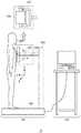
図1は、本実施形態に係る心磁計測装置10の構成を示す。心磁計測装置10は、磁場計測装置の一例であって、磁気抵抗素子を用いて、人間の心臓の電気活動により生成される磁場である心磁を計測する。また、心磁計測装置10は、人間以外の生体の心磁を計測するために用いられてもよい。 FIG. 1 shows the configuration of themagnetocardiographic measuring device 10 according to the present embodiment. The magneticfield measuring device 10 is an example of a magnetic field measuring device, and uses a magnetoresistive element to measure a magnetic field, which is a magnetic field generated by the electrical activity of the human heart. Further, themagnetocardiographic measuring device 10 may be used for measuring the magnetocardiography of a living body other than a human being.

心磁計測装置10は、本体部100と、情報処理部150とを備える。本体部100は、被験者の心磁をセンシングするためのコンポーネントであり、磁気センサユニット110と、ヘッド120と、駆動部125と、ベース部130と、ポール部140とを有する。 Themagnetocardiographic measuring device 10 includes amain body unit 100 and aninformation processing unit 150. Themain body 100 is a component for sensing the magnetocardiography of the subject, and has amagnetic sensor unit 110, ahead 120, adrive unit 125, abase unit 130, and apole unit 140.

磁気センサユニット110は、心磁計測時に被験者の胸部における心臓に向かう位置に配置され、被験者の心磁をセンシングする。ヘッド120は、磁気センサユニット110を支持し、磁気センサユニット110を被験者に対向させる。駆動部125は、磁気センサユニット110およびヘッド120の間に設けられ、キャリブレーションを行う場合にヘッド120に対する磁気センサユニット110の向きを変更する。本実施形態に係る駆動部125は、図中のZ軸を中心に磁気センサユニット110を360度回転させることができる第1アクチュエータと、Z軸と垂直な軸(図中の状態においてはX軸)を中心に磁気センサユニット110を回転させる第2アクチュエータとを含み、これらを用いて磁気センサユニット110の方位角および天頂角を変更する。図中の駆動部125として示したように、駆動部125は図中のY軸方向から見るとY字形状を有し、第2アクチュエータは、磁気センサユニット110を図中X軸中心に360度回転させることができる。 Themagnetic sensor unit 110 is arranged at a position toward the heart in the chest of the subject at the time of magnetocardiography measurement, and senses the magnetocardiography of the subject. Thehead 120 supports themagnetic sensor unit 110 and makes themagnetic sensor unit 110 face the subject. Thedrive unit 125 is provided between themagnetic sensor unit 110 and thehead 120, and changes the orientation of themagnetic sensor unit 110 with respect to thehead 120 when performing calibration. Thedrive unit 125 according to the present embodiment has a first actuator capable of rotating themagnetic sensor unit 110 360 degrees around the Z axis in the drawing, and an axis perpendicular to the Z axis (X axis in the state in the drawing). ) Is included, and the second actuator that rotates themagnetic sensor unit 110 is included, and the azimuth angle and the zenith angle of themagnetic sensor unit 110 are changed by using these. As shown as thedrive unit 125 in the figure, thedrive unit 125 has a Y-shape when viewed from the Y-axis direction in the figure, and the second actuator has themagnetic sensor unit 110 360 degrees around the X-axis center in the figure. Can be rotated.

ベース部130は、他の部品を支える基台であり、本実施形態においては心磁計測時に被験者が乗る台となっている。ポール部140は、ヘッド120を被験者の胸部の高さに支持する。ポール部140は、磁気センサユニット110の高さを被験者の胸部の高さに調整するべく上下方向に伸縮可能であってよい。 Thebase portion 130 is a base that supports other parts, and in the present embodiment, is a base on which the subject rides during magnetocardiography measurement. Thepole portion 140 supports thehead 120 at the height of the subject's chest. Thepole portion 140 may be stretchable in the vertical direction so as to adjust the height of themagnetic sensor unit 110 to the height of the chest of the subject.

情報処理部150は、本体部100により計測したデータを処理して表示・印刷等により出力するためのコンポーネントである。情報処理部150は、PC(パーソナルコンピュータ)、タブレット型コンピュータ、スマートフォン、ワークステーション、サーバコンピュータ、または汎用コンピュータ等のコンピュータであってよく、複数のコンピュータが接続されたコンピュータシステムであってもよい。これに代えて、情報処理部150は、心磁計測の情報処理用に設計された専用コンピュータであってもよく、専用回線によって実現された専用ハードウェアであってもよい。 Theinformation processing unit 150 is a component for processing the data measured by themain body 100 and outputting it by display, printing, or the like. Theinformation processing unit 150 may be a computer such as a PC (personal computer), a tablet computer, a smartphone, a workstation, a server computer, or a general-purpose computer, or may be a computer system to which a plurality of computers are connected. Instead, theinformation processing unit 150 may be a dedicated computer designed for information processing of magnetocardiographic measurement, or dedicated hardware realized by a dedicated line.

図2は、本実施形態に係る磁気センサユニット110の構成を示す。磁気センサユニット110は、磁気センサアレイ210およびセンサデータ収集部230を有する。磁気センサアレイ210は、複数の磁気センサセル220を有し、三次元空間内の複数の箇所において3軸方向の入力磁場を検出可能である。本図において、磁気センサアレイ210は、X方向、Y方向およびZ方向のそれぞれに複数の磁気センサセル220(例えば、X方向に8個、Y方向に8個、およびZ方向に2個の計128個の磁気センサセル220)が平面状に配置されている。 FIG. 2 shows the configuration of themagnetic sensor unit 110 according to the present embodiment. Themagnetic sensor unit 110 includes amagnetic sensor array 210 and a sensordata acquisition unit 230. Themagnetic sensor array 210 has a plurality ofmagnetic sensor cells 220, and can detect input magnetic fields in the three axial directions at a plurality of locations in the three-dimensional space. In this figure, themagnetic sensor array 210 has a plurality ofmagnetic sensor cells 220 in each of the X direction, the Y direction, and the Z direction (for example, eight in the X direction, eight in the Y direction, and two in the Z direction, for a total of 128). The magnetic sensor cells 220) are arranged in a plane.

センサデータ収集部230は、磁気センサアレイ210に含まれる複数の磁気センサセル220に電気的に接続され(図示せず。)、複数の磁気センサセル220からのセンサデータ(検出信号)を収集して情報処理部150へと供給する。 The sensordata collection unit 230 is electrically connected to a plurality ofmagnetic sensor cells 220 included in the magnetic sensor array 210 (not shown), and collects sensor data (detection signals) from the plurality ofmagnetic sensor cells 220 to provide information. It is supplied to theprocessing unit 150.

図3は、本実施形態に係る磁気センサアレイ210中の磁気センサセル220の構成および配置を示す。複数の磁気センサセル220のそれぞれは、各々が磁気抵抗素子を有する少なくとも1つのセンサ部300を有する。本図においては、複数の磁気センサセル220のそれぞれが、3つのセンサ部300x〜z(「センサ部300」と総称する。)を有し、入力磁場を3軸方向で検出可能である場合を一例として示す。しかしながら、複数の磁気センサセル220のいずれもが、3つのセンサ部300x〜zを有することには限定されず、磁気センサアレイ210の少なくとも一部で、三次元空間内の複数の箇所において3軸方向の入力磁場を検出可能であればよい。センサ部300xはX軸方向に沿って配置されX軸方向の磁場を検出可能である。また、センサ部300yはY軸方向に沿って配置されY軸方向の磁場を検出可能である。また、センサ部300zはZ軸方向に沿って配置されZ軸方向の磁場を検出可能である。本図において一点鎖線で示される拡大図によって示されるように、本実施形態において、各センサ部300は、それぞれ、磁気抵抗素子の両端に磁気収束板が配置されている。したがって、各センサ部300は、磁気収束板に挟まれた狭い位置に配置された磁気抵抗素子を用いて磁場の空間分布をサンプリングすることにより、各軸方向において、空間におけるサンプリング点を明確にすることができる。各センサ部300の構成の詳細については後述する。 FIG. 3 shows the configuration and arrangement of themagnetic sensor cells 220 in themagnetic sensor array 210 according to the present embodiment. Each of the plurality ofmagnetic sensor cells 220 has at least onesensor unit 300, each of which has a magnetoresistive element. In this figure, an example is a case where each of the plurality ofmagnetic sensor cells 220 has threesensor units 300x to z (collectively referred to as “sensor unit 300”), and the input magnetic field can be detected in the three axial directions. Shown as. However, none of the plurality ofmagnetic sensor cells 220 is limited to having threesensor units 300x to z, and at least a part of themagnetic sensor array 210 has three axial directions at a plurality of locations in the three-dimensional space. It suffices if the input magnetic field of can be detected. Thesensor unit 300x is arranged along the X-axis direction and can detect the magnetic field in the X-axis direction. Further, thesensor unit 300y is arranged along the Y-axis direction and can detect the magnetic field in the Y-axis direction. Further, thesensor unit 300z is arranged along the Z-axis direction and can detect the magnetic field in the Z-axis direction. As shown by the enlarged view shown by the alternate long and short dash line in this figure, in the present embodiment, eachsensor unit 300 has magnetic convergence plates arranged at both ends of the magnetic resistance element. Therefore, eachsensor unit 300 clarifies the sampling points in space in each axial direction by sampling the spatial distribution of the magnetic field using the magnetoresistive element arranged at a narrow position sandwiched between the magnetic focusing plates. be able to. Details of the configuration of eachsensor unit 300 will be described later.

本図において、センサ部300x、300y、および300zにより検出する磁場の3軸方向と、磁気センサセル220を配列する三次元の方向とが同一方向である。これにより、測定磁場の分布の各成分の把握が容易となる。また、3つのセンサ部300x、300y、および300zは、各磁気センサセル220内において、磁気センサセル220を配列する三次元方向それぞれから見て互いに重ならず、かつ、3つのセンサ部300の間に設けるギャップ側に一端が設けられ、他端が当該ギャップから離れるように3軸方向の各軸方向に延伸して配置されていることが好ましい。一例として、本図において、磁気センサセル220の正面視左下の角部に空隙(ギャップ)が設けられ、センサ部300x、300y、および300zは、一端が当該空隙に接するように設けられ、他端が当該空隙から離れるようにX軸、Y軸、およびZ軸方向の各軸方向に延伸して配置されている例を示す。本図において、センサ部300x、300y、および300zが、立方体状の磁気センサセル220の一角部から互いに垂直な3辺に沿って配置され、該一角部に空隙が設けられている。しかしながら、検出する磁場の3軸方向と磁気センサセル220を配列する三次元の方向とは異なっていてもよい。例えば、検出する磁場の3軸方向としてX軸、Y軸、およびZ軸に代えて、極座標系のr軸、θ軸、およびφ軸を用いてもよい。また、磁気センサセル220を配列する三次元の方向として、X軸、Y軸およびZ軸に代えて、極座標系のr軸、θ軸、およびφ軸を用いてもよい。検出する磁場の3軸方向と磁気センサセル220を配列する三次元の方向とが異なる場合、磁気センサセル220内におけるセンサ部300の配置や、磁気センサセル220の配列方向に制約を受けることがなく、磁気センサアレイ210の設計の自由度を増すことができる。また、磁気センサセル220の角部にギャップを設けることなく、センサ部300x、300y、および300zが設けられてもよい。この場合、磁気センサセル220を小さく構成することができ、このため、このような複数の磁気センサセル220を有する磁気センサアレイ210を小型化することが可能となる。 In this figure, the three-axis directions of the magnetic fields detected by thesensor units 300x, 300y, and 300z and the three-dimensional directions in which themagnetic sensor cells 220 are arranged are the same directions. This makes it easy to grasp each component of the distribution of the measured magnetic field. Further, the threesensor units 300x, 300y, and 300z do not overlap each other when viewed from each of the three-dimensional directions in which themagnetic sensor cells 220 are arranged in eachmagnetic sensor cell 220, and are provided between the threesensor units 300. It is preferable that one end is provided on the gap side and the other end is extended in each of the three axial directions so as to be separated from the gap. As an example, in this figure, a gap is provided in the lower left corner of themagnetic sensor cell 220 when viewed from the front, and thesensor portions 300x, 300y, and 300z are provided so that one end is in contact with the gap and the other end is in contact with the gap. An example is shown in which the components are stretched in each of the X-axis, Y-axis, and Z-axis directions so as to be separated from the gap. In this figure, thesensor portions 300x, 300y, and 300z are arranged along three sides perpendicular to each other from one corner of the cubicmagnetic sensor cell 220, and a gap is provided in the corner. However, the three-axis direction of the magnetic field to be detected and the three-dimensional direction in which themagnetic sensor cells 220 are arranged may be different. For example, instead of the X-axis, Y-axis, and Z-axis, the r-axis, θ-axis, and φ-axis of the polar coordinate system may be used as the three-axis directions of the magnetic field to be detected. Further, as the three-dimensional direction in which themagnetic sensor cells 220 are arranged, the r-axis, θ-axis, and φ-axis of the polar coordinate system may be used instead of the X-axis, Y-axis, and Z-axis. When the three-axis direction of the magnetic field to be detected and the three-dimensional direction in which themagnetic sensor cells 220 are arranged are different, the magnetism is not restricted by the arrangement of thesensor unit 300 in themagnetic sensor cell 220 or the arrangement direction of themagnetic sensor cells 220. The degree of freedom in designing thesensor array 210 can be increased. Further, thesensor units 300x, 300y, and 300z may be provided without providing a gap at the corner portion of themagnetic sensor cell 220. In this case, themagnetic sensor cell 220 can be made smaller, and therefore, themagnetic sensor array 210 having such a plurality ofmagnetic sensor cells 220 can be made smaller.

図4は、本実施形態に係る磁気抵抗素子を有する磁気センサの入出力特性の一例を示す。本図は、横軸が磁気センサに入力する入力磁場の大きさBを示し、縦軸が磁気センサの検出信号の大きさV_xMR0を示す。磁気センサは、例えば、巨大磁気抵抗(GMR:Giant Magneto−Resistance)素子またはトンネル磁気抵抗(TMR:Tunnel Magneto−Resistance)素子等を有し、予め定められた一軸方向の磁場の大きさを検出する。 FIG. 4 shows an example of the input / output characteristics of the magnetic sensor having the magnetoresistive element according to the present embodiment. In this figure, the horizontal axis shows the magnitude B of the input magnetic field input to the magnetic sensor, and the vertical axis shows the magnitude V_xMR0 of the detection signal of the magnetic sensor. The magnetic sensor has, for example, a giant magneto-resistance (GMR) element or a tunnel magneto-resistance (TMR) element, and detects the magnitude of a predetermined uniaxial magnetic field. ..

このような磁気センサは、入力磁場Bに対する検出信号V_xMR0の傾きである磁気感度が高く、10pT程度の微小な磁場を検出することができる。その一方で、磁気センサは、例えば、入力磁場Bの絶対値が1μT程度で検出信号V_xMR0が飽和してしまい、入出力特性の直線性が良好な範囲が狭い。そこで、このような磁気センサにフィードバック磁場を発生させる閉ループを加えると、磁気センサの直線性を改善することができる。このような磁気センサについて次に説明する。 Such a magnetic sensor has high magnetic sensitivity, which is the gradient of the detection signal V_xMR0 with respect to the input magnetic field B, and can detect a minute magnetic field of about 10 pT. On the other hand, in the magnetic sensor, for example, when the absolute value of the input magnetic field B is about 1 μT, the detection signal V_xMR0 is saturated, and the range in which the linearity of the input / output characteristics is good is narrow. Therefore, by adding a closed loop that generates a feedback magnetic field to such a magnetic sensor, the linearity of the magnetic sensor can be improved. Such a magnetic sensor will be described below.

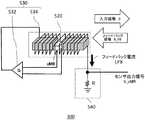
図5は、本実施形態に係るセンサ部300の構成例を示す。センサ部300は、複数の磁気センサセル220のそれぞれの内部に設けられ、磁気センサ520と、第1の磁場生成部530と、出力部540と、を含む。なお、センサ部300の一部、例えば第1の増幅回路532および出力部540は、磁気センサセル220側ではなくセンサデータ収集部230側に設けられてもよい。 FIG. 5 shows a configuration example of thesensor unit 300 according to the present embodiment. Thesensor unit 300 is provided inside each of the plurality ofmagnetic sensor cells 220, and includes amagnetic sensor 520, a first magneticfield generation unit 530, and anoutput unit 540. A part of thesensor unit 300, for example, thefirst amplifier circuit 532 and theoutput unit 540 may be provided on the sensordata acquisition unit 230 side instead of themagnetic sensor cell 220 side.

磁気センサ520は、図4で説明した磁気センサと同様に、GMR素子またはTMR素子等の磁気抵抗素子を有する。また、磁気センサ520のそれぞれは、磁気抵抗素子と磁気抵抗素子の両端に配置された二つの磁気収束板とを含み、磁気抵抗素子は、二つの磁気収束板に挟まれた位置に配置される。磁気センサ520が有する磁気抵抗素子は、感磁軸の正の方向を+X方向とした場合に、+X方向の磁場が入力すると抵抗値が増加し、−X方向の磁場が入力すると抵抗値が減少するように形成されてよい。即ち、磁気センサ520が有する磁気抵抗素子の抵抗値の変化を観測することにより、当該磁気センサ520に入力する磁場Bの大きさを検出することができる。例えば、磁気センサ520の磁気感度をSとすると、磁気センサ520の入力磁場Bに対する検出結果は、S×Bと算出できる。なお、磁気センサ520は、一例として、電源等が接続され、抵抗値の変化に応じた電圧降下を、入力磁場の検出結果として出力する。磁気センサ520の構成の詳細については後述する。 Themagnetic sensor 520 has a magnetoresistive element such as a GMR element or a TMR element, similar to the magnetic sensor described with reference to FIG. Further, each of themagnetic sensors 520 includes a magnetic resistance element and two magnetic convergence plates arranged at both ends of the magnetic resistance element, and the magnetic resistance elements are arranged at positions sandwiched between the two magnetic convergence plates. .. The magnetic resistance element of themagnetic sensor 520 increases the resistance value when a magnetic field in the + X direction is input, and decreases when a magnetic field in the -X direction is input, when the positive direction of the magnetic sensing axis is the + X direction. It may be formed to do so. That is, by observing the change in the resistance value of the magnetoresistive element possessed by themagnetic sensor 520, the magnitude of the magnetic field B input to themagnetic sensor 520 can be detected. For example, assuming that the magnetic sensitivity of themagnetic sensor 520 is S, the detection result of themagnetic sensor 520 with respect to the input magnetic field B can be calculated as S × B. As an example, themagnetic sensor 520 is connected to a power source or the like, and outputs a voltage drop according to a change in resistance value as a detection result of an input magnetic field. Details of the configuration of themagnetic sensor 520 will be described later.

第1の磁場生成部530は、出力部540が出力する出力信号に応じた大きさで、磁気センサ520が検出した入力磁場を低減させるフィードバック磁場を発生させ、磁気センサ520に与える。第1の磁場生成部530は、例えば、磁気センサ520に入力する磁場Bとは逆向きで、絶対値が当該入力磁場と略同一のフィードバック磁場B_FBを発生させ、入力磁場を打ち消すように動作する。第1の磁場生成部530は、第1の増幅回路532と、第1のコイル534とを含む。 The first magneticfield generation unit 530 generates a feedback magnetic field having a size corresponding to the output signal output by theoutput unit 540 and reducing the input magnetic field detected by themagnetic sensor 520, and gives the feedback magnetic field to themagnetic sensor 520. The first magneticfield generation unit 530, for example, generates a feedback magnetic field B_FB whose absolute value is substantially the same as that of the input magnetic field in the direction opposite to the magnetic field B input to themagnetic sensor 520, and operates so as to cancel the input magnetic field. .. The first magneticfield generation unit 530 includes afirst amplifier circuit 532 and afirst coil 534.

第1の増幅回路532は、磁気センサ520の入力磁場の検出結果に応じた電流をフィードバック電流I_FBとして出力する。磁気センサ520が有する磁気抵抗素子が、少なくとも1つの磁気抵抗素子を含むブリッジ回路により構成される場合、第1の増幅回路532の入力端子対には、ブリッジ回路の出力がそれぞれ接続される。そして、第1の増幅回路532は、ブリッジ回路の出力に応じた電流をフィードバック電流I_FBとして出力する。第1の増幅回路532は、例えば、トランスコンダクタンスアンプを含み、磁気センサ520の出力電圧に応じたフィードバック電流I_FBを出力する。例えば、第1の増幅回路532の電圧・電流変換係数をGとすると、フィードバック電流I_FBは、G×S×Bと算出できる。 Thefirst amplifier circuit 532 outputs a current corresponding to the detection result of the input magnetic field of themagnetic sensor 520 as the feedback current I_FB. When the reluctance element included in themagnetic sensor 520 is composed of a bridge circuit including at least one reluctance element, the output of the bridge circuit is connected to each input terminal pair of thefirst amplifier circuit 532. Then, thefirst amplifier circuit 532 outputs a current corresponding to the output of the bridge circuit as a feedback current I_FB. Thefirst amplifier circuit 532 includes, for example, a transconductance amplifier, and outputs a feedback current I_FB corresponding to the output voltage of themagnetic sensor 520. For example, assuming that the voltage / current conversion coefficient of thefirst amplifier circuit 532 is G, the feedback current I_FB can be calculated as G × S × B.

第1のコイル534は、フィードバック電流I_FBに応じたフィードバック磁場B_FBを発生させる。第1のコイル534は、磁気センサ520が有する磁気抵抗素子および磁気抵抗素子の両端に配置された二つの磁気収束板を取り囲むように、磁気センサ520が検出対象とする磁場の軸方向に沿って巻かれている。第1のコイル534は、磁気センサ520の全体にわたって均一のフィードバック磁場B_FBを発生させることが望ましい。例えば、第1のコイル534のコイル係数をβとすると、フィードバック磁場B_FBは、β×I_FBと算出できる。ここで、フィードバック磁場B_FBは、入力磁場Bを打ち消す向きに発生するので、磁気センサ520に入力する磁場は、B−B_FBに低減されることになる。したがって、フィードバック電流I_FBは、次式のように示される。

Figure 0006936405
Thefirst coil 534 generates a feedback magnetic field B_FB corresponding to the feedback current I_FB. Thefirst coil 534 surrounds the magnetic resistance element of themagnetic sensor 520 and the two magnetic focusing plates arranged at both ends of the magnetic resistance element, along the axial direction of the magnetic field to be detected by themagnetic sensor 520. It is rolled up. It is desirable that thefirst coil 534 generate a uniform feedback magnetic field B_FB throughout themagnetic sensor 520. For example, assuming that the coil coefficient of thefirst coil 534 is β, the feedback magnetic field B_FB can be calculated as β × I_FB. Here, since the feedback magnetic field B_FB is generated in a direction that cancels the input magnetic field B, the magnetic field input to themagnetic sensor 520 is reduced to BB_FB. Therefore, the feedback current I_FB is expressed by the following equation.
Figure 0006936405

(数1)式をフィードバック電流I_FBについて解くと、センサ部300の定常状態におけるフィードバック電流I_FBの値を算出することができる。磁気センサ520の磁気感度Sおよび第1の増幅回路532の電圧・電流変換係数Gが十分に大きいとすると、(数1)式から次式が算出される。

Figure 0006936405
When the equation (Equation 1) is solved for the feedback current I_FB, the value of the feedback current I_FB in the steady state of thesensor unit 300 can be calculated. Assuming that the magnetic sensitivity S of themagnetic sensor 520 and the voltage / current conversion coefficient G of thefirst amplifier circuit 532 are sufficiently large, the following equation is calculated from the equation (Equation 1).
Figure 0006936405

出力部540は、第1の磁場生成部530がフィードバック磁場B_FBを発生するために流すフィードバック電流I_FBに応じた出力信号V_xMRを出力する。出力部540は、例えば、抵抗値Rの抵抗性素子を有し、当該抵抗性素子にフィードバック電流I_FBが流れることによって生じる電圧降下を出力信号V_xMRとして出力する。この場合、出力信号V_xMRは、(数2)式より次式のように算出される。

Figure 0006936405
Theoutput unit 540 outputs an output signal V_xMR corresponding to the feedback current I_FB flowed by the first magneticfield generation unit 530 to generate the feedback magnetic field B_FB. Theoutput unit 540 has, for example, a resistance element having a resistance value R, and outputs a voltage drop caused by a feedback current I_FB flowing through the resistance element as an output signal V_xMR. In this case, the output signal V_xMR is calculated from the equation (Equation 2) as follows.
Figure 0006936405

以上のように、センサ部300は、外部から入力する磁場を低減させるフィードバック磁場を発生するので、磁気センサ520に実質的に入力する磁場を低減させる。これにより、センサ部300は、例えば、磁気センサ520として図4に示した非線形性であり、動作磁場範囲が狭い特性を有する磁気抵抗素子を用い、入力磁場Bの絶対値が1μTを超えても、検出信号V_xMRが飽和することを防止できる。このようなセンサ部300の入出力特性を次に説明する。 As described above, since thesensor unit 300 generates a feedback magnetic field that reduces the magnetic field input from the outside, the magnetic field that is substantially input to themagnetic sensor 520 is reduced. As a result, thesensor unit 300 uses, for example, a magnetoresistive element having the non-linearity shown in FIG. 4 as themagnetic sensor 520 and having a narrow operating magnetic field range, even if the absolute value of the input magnetic field B exceeds 1 μT. , It is possible to prevent the detection signal V_xMR from being saturated. The input / output characteristics of such asensor unit 300 will be described below.

図6は、本実施形態に係るセンサ部300の入出力特性の一例を示す。本図は、横軸がセンサ部300に入力する入力磁場の大きさBを示し、縦軸がセンサ部300の検出信号の大きさV_xMRを示す。センサ部300は、磁気感度が高く、10pT程度の微小な磁場を検出することができる。また、センサ部300は、例えば、入力磁場Bの絶対値が100μTを超えても、検出信号V_xMRの良好な線形性を保つことができる。 FIG. 6 shows an example of the input / output characteristics of thesensor unit 300 according to the present embodiment. In this figure, the horizontal axis shows the magnitude B of the input magnetic field input to thesensor unit 300, and the vertical axis shows the magnitude V_xMR of the detection signal of thesensor unit 300. Thesensor unit 300 has high magnetic sensitivity and can detect a minute magnetic field of about 10 pT. Further, thesensor unit 300 can maintain good linearity of the detection signal V_xMR even if the absolute value of the input magnetic field B exceeds 100 μT, for example.

即ち、本実施形態に係るセンサ部300は、例えば、入力磁場Bの絶対値が数百μT以下といった、予め定められた入力磁場Bの範囲において、当該入力磁場Bに対する検出結果が線形性を有するように構成される。このようなセンサ部300を用いることにより、心磁信号のように微弱な磁気的信号を簡便に検出することができる。 That is, in thesensor unit 300 according to the present embodiment, the detection result for the input magnetic field B has linearity in a predetermined range of the input magnetic field B, for example, the absolute value of the input magnetic field B is several hundred μT or less. It is configured as follows. By using such asensor unit 300, a weak magnetic signal such as a magnetocardiographic signal can be easily detected.

図7は、本実施形態に係る磁気センサ520の構成例を示す。本図において、磁気センサ520は、磁気抵抗素子710と、磁気抵抗素子710の両端に配置された磁気収束板720および730とを有する。磁気収束板720および730は、磁気抵抗素子710を間に挟むように、磁気抵抗素子710の両端に配置されている。本図において、磁気収束板720は、感磁軸に沿って磁気抵抗素子710の負側に設けられ、磁気収束板730は、感磁軸に沿って磁気抵抗素子710の正側に設けられている。なお、ここで、感磁軸は、磁気抵抗素子710を形成する磁化固定層において固定された磁化の方向に沿っていてよい。また、感磁軸の負側から正側に向かって磁場が入力されると、磁気抵抗素子710の抵抗は増加または減少してよい。磁気収束板720および730は、例えばパーマロイ等の透磁率の高い材料により形成される。そして、磁気センサ520が本図に示すように構成される場合、第1のコイル534は、磁気抵抗素子710と、磁気抵抗素子710の両端に配置された磁気収束板720および730との断面を取り囲むように、磁気センサ520が検出対象とする磁場の軸方向に沿って巻かれている。また、磁気センサ520は、1つの磁気センサ520内に複数の磁気抵抗素子710を有する場合、磁気抵抗素子およびその両端に配置された磁気収束板を含む組を複数有してもよい。その場合、磁気抵抗素子およびその両端に配置された磁気収束板を含む組を1つのコイルで取り囲むように第1のコイル534が巻かれてもよい。 FIG. 7 shows a configuration example of themagnetic sensor 520 according to the present embodiment. In this figure, themagnetic sensor 520 has amagnetoresistive element 710 and magnetic focusingplates 720 and 730 arranged at both ends of themagnetoresistive element 710. The magnetic focusingplates 720 and 730 are arranged at both ends of themagnetic resistance element 710 so as to sandwich themagnetic resistance element 710 between them. In this figure, themagnetic convergence plate 720 is provided on the negative side of themagnetoresistive element 710 along the magnetic sensing axis, and the magnetic focusingplate 730 is provided on the positive side of themagnetoresistive element 710 along the magnetic sensing axis. There is. Here, the magnetically sensitive axis may be along the direction of magnetization fixed in the magnetization fixing layer forming themagnetoresistive element 710. Further, when a magnetic field is input from the negative side to the positive side of the magnetic sensing shaft, the resistance of themagnetoresistive element 710 may increase or decrease. The magnetic focusingplates 720 and 730 are formed of a material having a high magnetic permeability such as permalloy. When themagnetic sensor 520 is configured as shown in this figure, thefirst coil 534 has a cross section of themagnetic resistance element 710 and themagnetic convergence plates 720 and 730 arranged at both ends of themagnetic resistance element 710. Themagnetic sensor 520 is wound along the axial direction of the magnetic field to be detected so as to surround it. Further, when themagnetic sensor 520 has a plurality ofmagnetoresistive elements 710 in onemagnetic sensor 520, themagnetic sensor 520 may have a plurality of sets including the magnetoresistive element and the magnetic focusing plates arranged at both ends thereof. In that case, thefirst coil 534 may be wound so as to surround the set including the magnetoresistive element and the magnetic focusing plates arranged at both ends thereof with one coil.

このような磁気センサ520において、感磁軸の負側から正側に磁場が入力されると、透磁率の高い材料で形成された磁気収束板720および730が磁化されることにより、本図において破線で示すような磁束の分布が発生する。すると、磁気収束板720および730が磁化されることにより発生する磁束は、二つの磁気収束板720および730の間に挟まれた磁気抵抗素子710の位置を通過することとなる。このため、磁気抵抗素子710の位置における磁束密度は、磁気収束板720および730を配置することによって大幅に増加させることができる。また、本図のように、磁気収束板720および730に挟まれた狭い位置に配置された磁気抵抗素子710を用いて磁場の空間分布をサンプリングすることにより、空間におけるサンプリング点を明確にすることができる。 In such amagnetic sensor 520, when a magnetic field is input from the negative side to the positive side of the magnetic sensing axis, the magnetic focusingplates 720 and 730 made of a material having high magnetic permeability are magnetized, so that in this figure, A magnetic flux distribution as shown by the broken line occurs. Then, the magnetic flux generated by magnetizing the magnetic focusingplates 720 and 730 passes through the position of thereluctance element 710 sandwiched between the two magnetic focusingplates 720 and 730. Therefore, the magnetic flux density at the position of thereluctance element 710 can be significantly increased by arranging the magnetic focusingplates 720 and 730. Further, as shown in this figure, the sampling points in space are clarified by sampling the spatial distribution of the magnetic field using themagnetoresistive element 710 arranged at a narrow position sandwiched between the magnetic focusingplates 720 and 730. Can be done.

図8は、本実施形態に係る磁気センサ520にフィードバック磁場を発生させた時の磁束分布を示す。図8においては、図7と同じ機能および構成を有する部材に対して同じ符号を付すとともに、以下相違点を除き説明を省略する。本実施形態に係る磁気センサ520において、第1のコイル534にフィードバック電流が供給されると、第1のコイル534がフィードバック磁場を発生させることにより、本図において一点鎖線で示すような磁束の分布が発生する。このフィードバック磁場により発生する磁束は、磁気抵抗素子710に入力され磁気収束板720および730によって磁気増幅された磁場の空間分布をキャンセルするように空間分布する。このため、磁気センサ520は、本図に示すように磁気抵抗素子710の両端に磁気収束板720および730が配置されている場合には、磁気抵抗素子710の位置における磁場分布をフィードバック磁場によって正確にキャンセルすることができるため、入力磁場と出力電圧との間の線形性が高いセンサを実現することができる。 FIG. 8 shows the magnetic flux distribution when a feedback magnetic field is generated in themagnetic sensor 520 according to the present embodiment. In FIG. 8, the members having the same functions and configurations as those in FIG. 7 are designated by the same reference numerals, and the description thereof will be omitted except for the following differences. In themagnetic sensor 520 according to the present embodiment, when a feedback current is supplied to thefirst coil 534, thefirst coil 534 generates a feedback magnetic field, so that the distribution of magnetic flux as shown by the alternate long and short dash line in this figure. Occurs. The magnetic flux generated by this feedback magnetic field is spatially distributed so as to cancel the spatial distribution of the magnetic field that is input to themagnetoresistive element 710 and magnetically amplified by the magnetic focusingplates 720 and 730. Therefore, when the magnetic focusingplates 720 and 730 are arranged at both ends of themagnetic resistance element 710, themagnetic sensor 520 accurately determines the magnetic field distribution at the position of themagnetic resistance element 710 by the feedback magnetic field. Since it can be canceled, a sensor with high linearity between the input magnetic field and the output voltage can be realized.

図9は、本実施形態に係るセンサ部300の他の構成例を示す。図9においては、図5と同じ機能および構成を有する部材に対して同じ符号を付すとともに、以下相違点を除き説明を省略する。本図におけるセンサ部300は、入力磁場Bから、入力磁場Bの大部分を占める環境磁場成分をキャンセルし、入力磁場Bに含まれる微小成分である心磁成分を高い分解能で検出する。本図において、センサ部300はさらに、電流DA変換器910および第2の磁場生成部920を更に含む。 FIG. 9 shows another configuration example of thesensor unit 300 according to the present embodiment. In FIG. 9, members having the same functions and configurations as those in FIG. 5 are designated by the same reference numerals, and the description thereof will be omitted except for the following differences. Thesensor unit 300 in this figure cancels the environmental magnetic field component that occupies most of the input magnetic field B from the input magnetic field B, and detects the magnetic component, which is a minute component contained in the input magnetic field B, with high resolution. In this figure, thesensor unit 300 further includes acurrent DA converter 910 and a second magneticfield generation unit 920.

電流DA変換器910は、デジタル値をアナログ電流に変換するDAコンバータである。電流DA変換器910は、入力磁場の各軸成分を検出した結果をデジタル信号で受け取り、当該デジタル信号に対応する電流値を第2の磁場生成部920に供給する。ここで、電流DA変換器910は、例えば、磁気センサアレイ210を用いて入力磁場Bを検出した場合に得られる複数のx軸成分Bxの平均値から算出された値を、x軸成分のデジタル信号として受け取ってよい。同様に、電流DA変換器910は、磁気センサアレイ210を用いて入力磁場Bを検出した場合に得られる複数のy軸成分Byの平均値から算出された値、および、z軸成分Bzの平均値から算出された値を、それぞれ、y軸成分のデジタル信号、および、z軸成分のデジタル信号として受け取ってよい。 Thecurrent DA converter 910 is a DA converter that converts a digital value into an analog current. Thecurrent DA converter 910 receives the result of detecting each axis component of the input magnetic field as a digital signal, and supplies the current value corresponding to the digital signal to the second magneticfield generation unit 920. Here, thecurrent DA converter 910 uses, for example, adigital sensor array 210 to digitally obtain a value calculated from the average value of a plurality of x-axis components Bx obtained when the input magnetic field B is detected. It may be received as a signal. Similarly, thecurrent DA converter 910 has a value calculated from the average value of a plurality of y-axis component By obtained when the input magnetic field B is detected by using themagnetic sensor array 210, and the average of the z-axis component Bz. The value calculated from the value may be received as a digital signal of the y-axis component and a digital signal of the z-axis component, respectively.

第2の磁場生成部920は、電流DA変換器910に接続され、電流DA変換器910から供給された電流値に応じた大きさで、入力磁場Bの大部分を占める環境磁場を低減させるキャンセル磁場B_Envを発生させ、それを磁気センサ520に与える。第2の磁場生成部920は、例えば、環境磁場とは逆向きで、絶対値が当該環境磁場と略同一のキャンセル磁場B_Envを発生させ、環境磁場を打ち消すように動作する。第2の磁場生成部920は、第2の増幅回路922と、第2のコイル924とを含む。 The secondmagnetic field generator 920 is connected to thecurrent DA converter 910 and has a size corresponding to the current value supplied from thecurrent DA converter 910 to reduce the environmental magnetic field that occupies most of the input magnetic field B. A magnetic field B_Env is generated and applied to themagnetic sensor 520. The second magneticfield generation unit 920, for example, generates a cancel magnetic field B_Env having an absolute value substantially the same as that of the environmental magnetic field in the opposite direction to the environmental magnetic field, and operates so as to cancel the environmental magnetic field. The second magneticfield generation unit 920 includes asecond amplifier circuit 922 and asecond coil 924.

第2の増幅回路922は、電流DA変換器910および第2のコイル924に接続され、電流DA変換器910から供給された電流値に応じた電流をキャンセル電流I_Compとして出力する。 Thesecond amplifier circuit 922 is connected to thecurrent DA converter 910 and thesecond coil 924, and outputs a current corresponding to the current value supplied from thecurrent DA converter 910 as a cancel current I_Comp.

第2のコイル924は、一端が第2の増幅回路922に接続され、他端が接地されている。第2のコイル924は、第2の増幅回路922から供給されたキャンセル電流I_Compに応じたキャンセル磁場B_Envを発生させる。第2のコイル924は、磁気センサ520が有する磁気抵抗素子710および磁気抵抗素子710の両端に配置された二つの磁気収束板720および730を取り囲むように、磁気センサ520が検出対象とする磁場の軸方向に沿って巻かれている。第2のコイル924は、磁気センサ520の全体にわたって均一のキャンセル磁場B_Envを発生させることが望ましい。例えば、第2のコイル924のコイル係数をβ2とすると、キャンセル磁場B_Envは、β2×I_Compと算出できる。ここで、キャンセル磁場B_Envは、入力磁場Bを打ち消す向きに発生するので、磁気センサ520に入力する磁場は、B−B_Envに低減されることになる。 One end of thesecond coil 924 is connected to thesecond amplifier circuit 922, and the other end is grounded. Thesecond coil 924 generates a cancel magnetic field B_Env corresponding to the cancel current I_Comp supplied from thesecond amplifier circuit 922. Thesecond coil 924 is a magnetic field to be detected by themagnetic sensor 520 so as to surround the two magnetic focusingplates 720 and 730 arranged at both ends of themagnetic resistance element 710 and themagnetic resistance element 710 of themagnetic sensor 520. It is wound along the axial direction. It is desirable that thesecond coil 924 generate a uniform canceling magnetic field B_Env throughout themagnetic sensor 520. For example, assuming that the coil coefficient of thesecond coil 924 is β2, the cancel magnetic field B_Env can be calculated as β2 × I_Comp. Here, since the cancel magnetic field B_Env is generated in the direction of canceling the input magnetic field B, the magnetic field input to themagnetic sensor 520 is reduced to BB_Env.

なお、第1のコイル534に加えて、当該第2のコイル924を、磁気抵抗素子710および磁気抵抗素子710の両端に配置された二つの磁気収束板720および730に巻く場合には、第1のコイル534および第2のコイル924の2本を並列に磁気抵抗素子710および磁気収束板720、730に巻いてよい。 When thesecond coil 924 is wound around themagnetic reluctance element 710 and the two magnetic focusingplates 720 and 730 arranged at both ends of thereluctance element 710 in addition to thefirst coil 534, the first coil is used. Thecoil 534 and thesecond coil 924 may be wound in parallel around thereluctance element 710 and the magnetic focusingplates 720 and 730.

複数の磁気センサセル220のそれぞれは、磁気センサ520として本図に示すような磁気センサ520を採用することにより、磁気センサが検出する入力磁場に含まれる環境磁場を低減させるキャンセル磁場を発生させる第2の磁場生成部を更に含んでよい。これにより、心磁計測装置10の磁気センサアレイ210は、各軸方向について、入力磁場Bの大部分を占める環境磁場が、キャンセル磁場B_Envで減殺された合成磁場を検出するので、入力磁場Bの微小成分である心磁成分を高い分解能で検出することができる。 Each of the plurality ofmagnetic sensor cells 220 employs amagnetic sensor 520 as shown in this figure as themagnetic sensor 520, thereby generating a second cancel magnetic field that reduces the environmental magnetic field included in the input magnetic field detected by the magnetic sensor. The magnetic field generator of the above may be further included. As a result, themagnetic sensor array 210 of the magneticfield measuring device 10 detects the combined magnetic field in which the environmental magnetic field occupying most of the input magnetic field B is attenuated by the cancel magnetic field B_Env in each axial direction. It is possible to detect a magnetic component, which is a minute component, with high resolution.

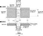
図10は、本実施形態に係る磁気センサ520の構成の具体例を示す。図10においては、図7と同じ機能および構成を有する部材に対して同じ符号を付すとともに、以下相違点を除き説明を省略する。本図において、磁気抵抗素子710は、磁化自由層1010および磁化固定層1020を有する。一般に、磁気抵抗素子710は、絶縁体の薄膜層を二つの強磁性体層で挟み込んだ構造である。磁化自由層1010は、二つの強磁性体層のうち、磁化方向が外部磁界に応じて変化する層である。また、磁化固定層1020は、二つの強磁性体層のうち、磁化方向が外部磁界に対して変化しない層である。 FIG. 10 shows a specific example of the configuration of themagnetic sensor 520 according to the present embodiment. In FIG. 10, members having the same functions and configurations as those in FIG. 7 are designated by the same reference numerals, and the description thereof will be omitted except for the following differences. In this figure, themagnetoresistive element 710 has a magnetizationfree layer 1010 and a magnetization fixedlayer 1020. Generally, themagnetoresistive element 710 has a structure in which a thin film layer of an insulator is sandwiched between two ferromagnetic layers. The magnetizationfree layer 1010 is a layer in which the magnetization direction changes according to an external magnetic field among the two ferromagnetic layers. Further, themagnetization fixing layer 1020 is a layer of the two ferromagnetic layers whose magnetization direction does not change with respect to an external magnetic field.

本具体例において、磁気抵抗素子710は、磁化自由層1010が下部に配置され、磁化自由層1010の上部に絶縁体の薄膜層(図示せず)を介して磁化固定層1020が配置される、いわゆるボトムフリー構造の磁気抵抗素子である。ボトムフリー構造の磁気抵抗素子は、磁化自由層1010を比較的広い面積で形成することができるため、高い磁気感度を得ることができる。 In this specific example, in themagnetoresistive element 710, the magnetizationfree layer 1010 is arranged at the lower part, and the magnetization fixedlayer 1020 is arranged at the upper part of the magnetizationfree layer 1010 via a thin film layer (not shown) of an insulator. It is a so-called bottom-free structure magnetic resistance element. In the magnetic resistance element having a bottom-free structure, the magnetizationfree layer 1010 can be formed in a relatively large area, so that high magnetic sensitivity can be obtained.

また、本具体例において、磁気センサ520は、磁気抵抗素子710の上部に絶縁層(図示せず)を介して磁気収束板720および730が、磁気抵抗素子710を中央に挟むようにその両端に配置されている。これにより、磁気抵抗素子710は、磁気収束板720および730に挟まれた狭い空間に配置される。 Further, in this specific example, in themagnetic sensor 520, the magnetic focusingplates 720 and 730 are placed on the upper part of themagnetoresistive element 710 via an insulating layer (not shown) at both ends so as to sandwich themagnetoresistive element 710 in the center. Have been placed. As a result, themagnetoresistive element 710 is arranged in a narrow space sandwiched between the magnetic focusingplates 720 and 730.

ここで、本図において、磁化自由層1010における感磁軸方向に沿った長さを磁化自由層長さL_Freeと定義する。また、磁化自由層1010における上面視で感磁軸方向に垂直な軸に沿った長さを磁化自由層幅W_Freeと定義する。また、磁化固定層1020における感磁軸方向に沿った長さを磁化固定層長さL_Pinと定義する。また、磁化固定層1020における上面視で感磁軸方向に垂直な軸に沿った長さを磁化固定層幅W_Pinと定義する。また、磁気収束板の外側の一端から磁化自由層の外側の一端までの感磁軸方向に沿った長さ(本図において、磁気収束板720の左端から右端までの感磁軸方向に沿った長さ、および、磁気収束板730の右端から左端までの感磁軸方向に沿った長さ)を磁気収束板長さL_FCと定義する。また、磁気収束板における上面視で感磁軸方向に垂直な軸に沿った長さを磁気収束板幅W_FCと定義する。また、磁気収束板における側面視で感磁軸方向に垂直な軸に沿った長さを磁気収束板厚さT_FCと定義する。また、二つの磁気収束板720および730の感磁軸方向に沿った間隔(本図において、磁気収束板720の右端から磁気収束板730の左端までの感磁軸方向に沿った長さ)を磁気収束板間隔G_FCと定義する。また、磁化自由層1010の厚み方向の中心から磁気収束板の底面までの、側面視で感磁軸方向に垂直な軸に沿った間隔を磁気収束板高さH_FCと定義する。 Here, in this figure, the length of the magnetizedfree layer 1010 along the magnetic field axis direction is defined as the magnetized free layer length L_Free. Further, the length along the axis perpendicular to the magnetic field axis direction in the top view of the magnetizationfree layer 1010 is defined as the magnetization free layer width W_Free. Further, the length of the magnetized fixedlayer 1020 along the magnetic field axis direction is defined as the magnetized fixed layer length L_Pin. Further, the length along the axis perpendicular to the magnetic field axis direction in the top view of themagnetization fixing layer 1020 is defined as the magnetization fixing layer width W_Pin. Further, the length along the magnetic field axis direction from the outer end of the magnetic convergence plate to the outer end of the magnetization free layer (in this figure, along the magnetic field axis direction from the left end to the right end of the magnetic convergence plate 720). The length and the length along the magnetic field axis direction from the right end to the left end of the magnetic convergence plate 730) are defined as the magnetic convergence plate length L_FC. Further, the length along the axis perpendicular to the magnetic sensing axis direction in the top view of the magnetic focusing plate is defined as the magnetic focusing plate width W_FC. Further, the length along the axis perpendicular to the magnetic sensing axis direction in the side view of the magnetic focusing plate is defined as the magnetic focusing plate thickness T_FC. Further, the distance between the two magnetic focusingplates 720 and 730 along the magnetic sensing axis direction (the length along the magnetic sensing axis direction from the right end of the magnetic focusingplate 720 to the left end of the magnetic focusingplate 730 in this figure) is set. It is defined as the magnetic focusing plate spacing G_FC. Further, the distance from the center of the magnetizationfree layer 1010 in the thickness direction to the bottom surface of the magnetic convergence plate along the axis perpendicular to the magnetic sensing axis direction in the side view is defined as the magnetic convergence plate height H_FC.

図11は、本具体例に係る磁気センサ520において、磁気収束板間隔G_FCを変えた場合の磁気増幅率のシミュレーション結果を示す。本図において、横軸は磁気収束板間隔G_FCをμm単位で示し、縦軸は磁気増幅率を示す。ここで、本シミュレーションにおいて、磁化自由層長さL_Freeは100μm、磁化自由層幅W_Freeは140μm、磁化固定層長さL_Pinは40μm、磁化固定層幅W_Pinは20μm、磁気収束板幅W_FCは300μm、磁気収束板高さH_FCは0.6μmとした。これらのパラメータについては以下に示すシミュレーションにおいても全て共通の値とした。本シミュレーションにおいては、さらに、磁気収束板長さL_FCは10mmとし、磁気収束板厚さT_FCは10μm、30μm、50μm、および100μmとしてシミュレーションを行った。 FIG. 11 shows a simulation result of the magnetic amplification factor when the magnetic focusing plate spacing G_FC is changed in themagnetic sensor 520 according to this specific example. In this figure, the horizontal axis represents the magnetic focusing plate spacing G_FC in μm units, and the vertical axis represents the magnetic amplification factor. Here, in this simulation, the magnetized free layer length L_Free is 100 μm, the magnetized free layer width W_Free is 140 μm, the magnetized fixed layer length L_Pin is 40 μm, the magnetized fixed layer width W_Pin is 20 μm, the magnetic convergence plate width W_FC is 300 μm, and the magnetism. The height of the converging plate H_FC was set to 0.6 μm. All of these parameters were set to common values in the simulations shown below. In this simulation, the magnetic convergence plate length L_FC was 10 mm, and the magnetic convergence plate thickness T_FC was 10 μm, 30 μm, 50 μm, and 100 μm.

本図に示されるように、磁気センサ520は、磁気収束板間隔G_FCを狭めるほど磁気増幅率が高くなっている。ここで、磁化自由層長さL_Freeが100μmであるので、磁気収束板間隔G_FCが100μmである場合、側面視において、磁気収束板の側面と磁化自由層1010の側面が揃う(すなわち、図10において、磁気収束板720の右端と磁化自由層1010の左端、および、磁気収束板730の左端と磁化自由層1010の右端が側面視で揃う)こととなる。本シミュレーション結果によれば、磁気センサ520は、磁気収束板間隔G_FCが100μmよりも小さい場合に、磁気増幅率がさらに高くなっている。したがって、磁気センサ520は、磁気抵抗素子710の両端に配置される磁気収束板720および730の感磁軸方向の間隔(磁気収束板間隔G_FC)が、磁気抵抗素子710の磁化自由層1010の感磁軸方向の長さ(磁化自由層長さL_Free)よりも小さいと、より高い磁気増幅率を得られるので好ましい。また、磁気センサ520は、磁気収束板間隔G_FCを磁化固定層長さL_Pin(40μm)よりも小さくしてもよい。すなわち、磁気センサ520は、磁気収束板が上面視で磁化固定層の一部と重複するように磁気収束板を配置してもよい。 As shown in this figure, the magnetic amplification factor of themagnetic sensor 520 increases as the magnetic focusing plate spacing G_FC is narrowed. Here, since the magnetization free layer length L_Free is 100 μm, when the magnetic convergence plate spacing G_FC is 100 μm, the side surface of the magnetic convergence plate and the side surface of the magnetizationfree layer 1010 are aligned (that is, in FIG. 10). , The right end of themagnetic convergence plate 720 and the left end of the magnetizationfree layer 1010, and the left end of themagnetic convergence plate 730 and the right end of the magnetizationfree layer 1010 are aligned in a side view). According to this simulation result, the magnetic amplification factor of themagnetic sensor 520 is further higher when the magnetic focusing plate spacing G_FC is smaller than 100 μm. Therefore, in themagnetic sensor 520, the distance between the magnetic focusingplates 720 and 730 arranged at both ends of themagnetic resistance element 710 in the magnetic field axis direction (magnetic convergence plate distance G_FC) is different from that of the magneticfree layer 1010 of themagnetic resistance element 710. It is preferable that the length is smaller than the length in the magnetic axis direction (magnetism free layer length L_Free) because a higher magnetic amplification factor can be obtained. Further, themagnetic sensor 520 may make the magnetic focusing plate spacing G_FC smaller than the magnetization fixed layer length L_Pin (40 μm). That is, in themagnetic sensor 520, the magnetic convergence plate may be arranged so that the magnetic convergence plate overlaps a part of the magnetization fixing layer in the top view.

図12は、本具体例に係る磁気センサ520において、磁気収束板長さL_FCを変えた場合の磁気増幅率のシミュレーション結果を示す。本図において、横軸は磁気収束板長さL_FCをmm単位で示し、縦軸は磁気増幅率を示す。本シミュレーションにおいては、磁気収束板厚さT_FCは10μm、磁気収束板間隔G_FCは20μmとしてシミュレーションを行った。 FIG. 12 shows a simulation result of the magnetic amplification factor when the magnetic focusing plate length L_FC is changed in themagnetic sensor 520 according to this specific example. In this figure, the horizontal axis represents the magnetic convergence plate length L_FC in mm, and the vertical axis represents the magnetic amplification factor. In this simulation, the magnetic converging plate thickness T_FC was set to 10 μm, and the magnetic converging plate spacing G_FC was set to 20 μm.

本図に示されるように、磁気センサ520は、磁気収束板長さL_FCを長くするほど磁気増幅率が高くなっている。これは、透磁率の高い材料で形成された磁気収束板を長くするほど、発生する磁束が増えるためであるといえる。したがって、磁気センサ520は、磁気抵抗素子710の両端に磁気収束板を設けるにあたって、設計上可能な限り磁気収束板の感磁軸方向の長さ(磁気収束板長さL_FC)を大きくすると、より高い磁気増幅率を得られるので好ましい。具体的に、磁気収束板の感磁軸方向の長さ(磁気収束板長さL_FC)は1mm以上であると、高い磁気増幅効果が得られるので好ましい。特に、本図に示されるように、磁気センサ520は、磁気収束板長さL_FCが10mmより小さい範囲では磁気増幅率の増加効果が高い。また、磁気収束板長さL_FCが10mm以上であれば、100倍以上の磁気増幅率が得られる。したがって、心磁計測において、微弱な心磁をより正確に検出するために、磁気収束板の感磁軸方向の長さ(磁気収束板長さL_FC)は10mm以上であるとより好ましい。 As shown in this figure, the magnetic amplification factor of themagnetic sensor 520 increases as the length of the magnetic focusing plate L_FC increases. It can be said that this is because the longer the magnetic focusing plate made of a material having a high magnetic permeability, the greater the magnetic flux generated. Therefore, in themagnetic sensor 520, when the magnetic convergence plates are provided at both ends of themagnetoresistive element 710, the length of the magnetic convergence plate in the magnetic field axis direction (magnetic convergence plate length L_FC) should be increased as much as possible by design. It is preferable because a high magnetic amplification factor can be obtained. Specifically, when the length of the magnetic converging plate in the magnetic field axis direction (magnetic converging plate length L_FC) is 1 mm or more, a high magnetic amplification effect can be obtained, which is preferable. In particular, as shown in this figure, themagnetic sensor 520 has a high effect of increasing the magnetic amplification factor in the range where the magnetic focusing plate length L_FC is smaller than 10 mm. Further, if the magnetic focusing plate length L_FC is 10 mm or more, a magnetic amplification factor of 100 times or more can be obtained. Therefore, in the magnetocardiographic measurement, the length of the magnetic convergence plate in the magnetic field axis direction (magnetic convergence plate length L_FC) is more preferably 10 mm or more in order to detect weak magnetism more accurately.

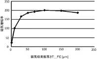
図13は、本具体例に係る磁気センサ520において、磁気収束板厚さT_FCを変えた場合の磁気増幅率のシミュレーション結果を示す。本図において、横軸は磁気収束板厚さT_FCをμm単位で示し、縦軸は磁気増幅率を示す。本シミュレーションにおいては、磁気収束板長さL_FCは10mm、磁気収束板厚さT_FCは10μm、磁気収束板間隔G_FCは20μmとしてシミュレーションを行った。 FIG. 13 shows a simulation result of the magnetic amplification factor when the magnetic focusing plate thickness T_FC is changed in themagnetic sensor 520 according to this specific example. In this figure, the horizontal axis represents the magnetic convergence plate thickness T_FC in μm units, and the vertical axis represents the magnetic amplification factor. In this simulation, the magnetic converging plate length L_FC was 10 mm, the magnetic converging plate thickness T_FC was 10 μm, and the magnetic converging plate spacing G_FC was 20 μm.

本図に示されるように、磁気センサ520は、磁気収束板厚さT_FCを厚くしていくと、ある点まで磁気増幅率は増加していき、その後、磁気増幅率が減少していく傾向にある。これは、ある点までは透磁率の高い材料で形成された磁気収束板を厚くするほど、発生する磁束が増えるため磁気増幅率が増加し、ある点を過ぎると、その磁気増幅効果よりも磁気収束板の厚み方向の中心が磁気抵抗素子710から遠ざかり、磁気収束板により収束させた磁束が磁気抵抗素子710を通過しにくくなる影響が強くなるためといえる。したがって、磁気収束板の厚さ(磁気収束板厚さT_FC)は、概ね100μm以内であると、より高い磁気増幅効果が得られるので好ましい。 As shown in this figure, in themagnetic sensor 520, as the magnetic convergence plate thickness T_FC is increased, the magnetic amplification factor tends to increase up to a certain point, and then the magnetic amplification factor tends to decrease. be. This is because the thicker the magnetic focusing plate made of a material with high magnetic permeability up to a certain point, the more magnetic flux is generated, so the magnetic amplification factor increases, and after a certain point, the magnetism is greater than the magnetic amplification effect. It can be said that the center of the converging plate in the thickness direction moves away from themagnetic resistance element 710, and the influence that the magnetic flux converged by the magnetic converging plate becomes difficult to pass through themagnetic resistance element 710 becomes stronger. Therefore, when the thickness of the magnetic converging plate (magnetic converging plate thickness T_FC) is approximately 100 μm or less, a higher magnetic amplification effect can be obtained, which is preferable.

図14は、本具体例に係る磁気センサ520において、磁気収束板間隔G_FCを一定として、磁気収束板長さL_FC/磁気収束板間隔G_FCを変えた場合の、磁気増幅率のシミュレーション結果を示す。本図において、横軸は磁気収束板長さL_FCを磁気収束板間隔G_FCで割った値を示し、縦軸は磁気増幅率を示す。本シミュレーションにおいては、磁気収束板厚さT_FCは10μm、磁気収束板間隔G_FCは20μmとしてシミュレーションを行った。 FIG. 14 shows a simulation result of the magnetic amplification factor when the magnetic convergence plate length L_FC / magnetic convergence plate interval G_FC is changed while the magnetic convergence plate interval G_FC is constant in themagnetic sensor 520 according to this specific example. In this figure, the horizontal axis represents the value obtained by dividing the magnetic convergence plate length L_FC by the magnetic convergence plate spacing G_FC, and the vertical axis represents the magnetic amplification factor. In this simulation, the magnetic converging plate thickness T_FC was set to 10 μm, and the magnetic converging plate spacing G_FC was set to 20 μm.

図14に示されるように、磁気センサ520は、磁気収束板長さL_FC/磁気収束板間隔G_FCが大きくなるほど磁気増幅率が高くなっている。これは、図11において磁気収束間隔G_FCが小さくなるほど磁気増幅率が高くなること、および、図12において磁気収束板長さL_FCが長くなるほど磁気増幅率が高くなることを反映しているといえる。本図に示されるように、磁気センサ520は、磁気収束板の感磁軸方向の長さ(磁気収束板長さL_FC)が、磁気抵抗素子710の両端に配置される磁気収束板720および730の感磁軸方向の間隔(磁気収束板間隔G_FC)の10倍より大きいと、高い磁気増幅効果が得られるので好ましい。特に、磁気センサ520は、磁気抵抗素子710の両端に配置される磁気収束板720および730の感磁軸方向の間隔(磁気収束板間隔G_FC)が、磁気抵抗素子710の磁化自由層1010の感磁軸方向の長さ(磁化自由層長さL_Free)よりも小さく、磁気収束板の感磁軸方向の長さ(磁気収束板長さL_FC)が、磁気抵抗素子710の磁化自由層1010の感磁軸方向の長さの10倍より大きいと、より高い磁気増幅効果が得られるのでより好ましい。さらに、磁気センサ520は、図11のシミュレーション結果から磁化自由層長さが100μmである場合、磁気収束板間隔G_FCが100μmより小さいことがより好ましく、図12のシミュレーション結果から10mm以上であることがより好ましいことが示されており、これらを踏まえて、磁気収束板の感磁軸方向の長さ(磁気収束板長さL_FC)が、磁気抵抗素子710の両端に配置される磁気収束板720および730の感磁軸方向の間隔(磁気収束板間隔G_FC)の100倍以上であると、より高い磁気増幅率を得られるのでより好ましい。このように、磁気センサ520は、磁気収束板長さL_FCと磁気収束板間隔G_FCとを適切に設計することにより、高い磁気増幅率を実現することができる。 As shown in FIG. 14, in themagnetic sensor 520, the magnetic amplification factor increases as the magnetic focusing plate length L_FC / magnetic focusing plate spacing G_FC increases. It can be said that this reflects that the smaller the magnetic convergence interval G_FC in FIG. 11, the higher the magnetic amplification factor, and in FIG. 12, the longer the magnetic convergence plate length L_FC, the higher the magnetic amplification factor. As shown in this figure, in themagnetic sensor 520, the length of the magnetic convergence plate in the magnetic field axis direction (magnetic convergence plate length L_FC) is arranged at both ends of themagnetoresistive element 710, and themagnetic convergence plates 720 and 730 are arranged. When it is larger than 10 times the interval in the magnetic field axis direction (magnetic focusing plate interval G_FC), a high magnetic amplification effect can be obtained, which is preferable. In particular, in themagnetic sensor 520, the distance between themagnetic convergence plates 720 and 730 arranged at both ends of themagnetic resistance element 710 in the magnetic field axis direction (magnetic convergence plate distance G_FC) is different from that of the magneticfree layer 1010 of themagnetic resistance element 710. The length in the magnetic axis direction (magnetism free layer length L_Free) is smaller, and the length of the magnetic convergence plate in the magnetic axis direction (magnetic convergence plate length L_FC) is the feeling of the magnetizationfree layer 1010 of themagnetic resistance element 710. If it is larger than 10 times the length in the magnetic axis direction, a higher magnetic amplification effect can be obtained, which is more preferable. Further, in themagnetic sensor 520, when the magnetizing free layer length is 100 μm from the simulation result of FIG. 11, the magnetic focusing plate spacing G_FC is more preferably smaller than 100 μm, and it is 10 mm or more from the simulation result of FIG. It has been shown that it is more preferable, and based on these, the length of the magnetic converging plate in the magnetic field axis direction (magnetic converging plate length L_FC) is determined by the magnetic convergingplates 720 and the magnetic convergingplates 720 arranged at both ends of themagnetic resistance element 710. It is more preferable that the distance of 730 in the magnetic field axis direction (magnetic focusing plate distance G_FC) is 100 times or more, because a higher magnetic amplification factor can be obtained. As described above, themagnetic sensor 520 can realize a high magnetic amplification factor by appropriately designing the magnetic focusing plate length L_FC and the magnetic focusing plate spacing G_FC.

図15は、本具体例に係る磁気センサ520において、磁気収束板長さL_FCを一定として、磁気収束板長さL_FC/磁気収束板間隔G_FCを変えた場合の、磁気増幅率のシミュレーション結果を示す。本図において、横軸は磁気収束板長さL_FCを磁気収束板間隔G_FCで割った値を示し、縦軸は磁気増幅率を示す。本シミュレーションにおいては、磁気収束板長さL_FCは10mmとし、磁気収束板厚さT_FCは10μm、30μm、50μm、および100μmとしてシミュレーションを行った。 FIG. 15 shows a simulation result of the magnetic amplification factor when the magnetic convergence plate length L_FC is constant and the magnetic convergence plate length L_FC / magnetic convergence plate interval G_FC is changed in themagnetic sensor 520 according to this specific example. .. In this figure, the horizontal axis represents the value obtained by dividing the magnetic convergence plate length L_FC by the magnetic convergence plate spacing G_FC, and the vertical axis represents the magnetic amplification factor. In this simulation, the magnetic converging plate length L_FC was set to 10 mm, and the magnetic converging plate thickness T_FC was set to 10 μm, 30 μm, 50 μm, and 100 μm.

図16は、本実施形態に係る磁気センサ520を、磁気センサアレイ210における複数の磁気センサセル220のセンサ部300に適用した例を示す。図16においては、図3と同じ機能および構成を有する部材に対して同じ符号を付すとともに、以下相違点を除き説明を省略する。本図において、複数の磁気センサセル220は、3つのセンサ部300x、300y、および300zにおける磁気センサ520として図7に示す構成例に係る磁気センサ520を用いる。複数の磁気センサセル220は、それぞれのセンサ部300に磁気抵抗素子710の両端に磁気収束板720および730が配置された磁気センサ520を用いることにより、上述したような磁気増幅効果を得るとともに、空間におけるサンプリング点を明確にすることができる。 FIG. 16 shows an example in which themagnetic sensor 520 according to the present embodiment is applied to thesensor unit 300 of a plurality ofmagnetic sensor cells 220 in themagnetic sensor array 210. In FIG. 16, members having the same functions and configurations as those in FIG. 3 are designated by the same reference numerals, and the description thereof will be omitted except for the following differences. In this figure, the plurality ofmagnetic sensor cells 220 use themagnetic sensor 520 according to the configuration example shown in FIG. 7 as themagnetic sensor 520 in the threesensor units 300x, 300y, and 300z. The plurality ofmagnetic sensor cells 220 obtain the above-mentioned magnetic amplification effect and space by using themagnetic sensors 520 in which themagnetic convergence plates 720 and 730 are arranged at both ends of themagnetoresistive element 710 in eachsensor unit 300. The sampling point in can be clarified.

また、心磁計測装置10は、複数の磁気センサセル220のそれぞれのセンサ部300における磁気センサ520として、磁気収束板長さL_FCと磁気収束板間隔G_FCとが最適化された磁気センサ520を用いることにより、例えば100倍を超える磁気増幅率を実現することができ、心磁計測において、微弱な心磁をより正確に検出することが可能となる。 Further, the magneticfield measuring device 10 uses amagnetic sensor 520 in which the magnetic focusing plate length L_FC and the magnetic focusing plate spacing G_FC are optimized as themagnetic sensor 520 in eachsensor unit 300 of the plurality ofmagnetic sensor cells 220. As a result, for example, a magnetic amplification factor exceeding 100 times can be realized, and weak magnetism can be detected more accurately in the magnetometer measurement.

さらに、本図に示すように、複数の磁気センサセル220における3軸の磁気センサであるセンサ部300x、300y、および300zは、X軸、Y軸、およびZ軸の三次元方向それぞれから見て、互いに重ならず、かつ、3軸の磁気センサの間に設けるギャップに一端が設けられ、他端が当該ギャップから離れるように3軸方向の各軸方向に延伸して配置されている。一例として、本図において、磁気センサセル220の正面視左下の角部に空隙(ギャップ)が設けられ、センサ部300x、300y、および300zは、一端が当該空隙に接するように設けられ、他端が当該空隙から離れるように、X軸、Y軸、およびZ軸方向の各軸方向に延伸して配置されている例を示す。本図に示すように、センサ部300x、300y、および300zが有するコイルまたは磁性体が、互いに重ならないように配置されていることは、以下の点で好ましい。まず、互いに重ならない配置により、サンプリング点をさらに明確にでき、磁場の各成分の把握がさらに容易となる。また、センサ部300x、300y、および300zが有する他軸感度を互いに等価なものとみなすことができ、線形代数の較正演算が容易となる。なお、この他軸感度は、センサ部300x、300y、および300zが有するコイル、または磁性体による相互干渉によって発生するものである。複数の磁気センサセル220のそれぞれのセンサ部300をこのような構成とすることにより、心磁計測装置10は、心磁計測において、微弱な心磁をより正確に検出することが可能となる。他の一例として、磁気センサセル220の角部にギャップを設けることなく、センサ部300x、300y、および300zが設けられてもよい。この場合、磁気センサセル220を小さく構成することができ、このため、このような複数の磁気センサセル220を有する磁気センサアレイ210を小型化することが可能となる。 Further, as shown in this figure, thesensor units 300x, 300y, and 300z, which are three-axis magnetic sensors in the plurality ofmagnetic sensor cells 220, are viewed from the three-dimensional directions of the X-axis, Y-axis, and Z-axis, respectively. One end is provided in a gap provided between the three-axis magnetic sensors that does not overlap with each other, and the other end is extended in each of the three axial directions so as to be separated from the gap. As an example, in this figure, a gap is provided in the lower left corner of themagnetic sensor cell 220 when viewed from the front, and thesensor portions 300x, 300y, and 300z are provided so that one end is in contact with the gap and the other end is in contact with the gap. An example is shown in which the particles are stretched in each of the X-axis, Y-axis, and Z-axis directions so as to be separated from the gap. As shown in this figure, it is preferable that the coils or magnetic materials of thesensor units 300x, 300y, and 300z are arranged so as not to overlap each other in the following points. First, by arranging them so as not to overlap each other, the sampling points can be further clarified, and it becomes easier to grasp each component of the magnetic field. Further, the other-axis sensitivity of thesensor units 300x, 300y, and 300z can be regarded as equivalent to each other, and the calibration calculation of the linear algebra becomes easy. The other axis sensitivity is generated by mutual interference of the coils or magnetic materials of thesensor units 300x, 300y, and 300z. By having eachsensor unit 300 of the plurality ofmagnetic sensor cells 220 having such a configuration, themagnetocardiographic measuring device 10 can more accurately detect a weak magnetocardiogram in the magnetocardiographic measurement. As another example, thesensor units 300x, 300y, and 300z may be provided without providing a gap at the corner portion of themagnetic sensor cell 220. In this case, themagnetic sensor cell 220 can be made smaller, and therefore, themagnetic sensor array 210 having such a plurality ofmagnetic sensor cells 220 can be made smaller.

また、磁気センサアレイ210は、複数の磁気センサセル220が互いに最近接させる形で配置されている。心磁計測装置においては、心磁の空間分布を計測することによって心臓における電気活動を検出するため、隣接する磁気センサセル220は、互いに近接して配置されていることが望ましく、例えば、虚血性心不全の診断などで用いられる場合には、必要な空間分解能を得るために、感磁軸方向に隣接するセンサ部の間隔(本図におけるL)を3cm以下とすることが望ましい。 Further, themagnetic sensor array 210 is arranged so that a plurality ofmagnetic sensor cells 220 are in close contact with each other. In the magnetic field measuring device, in order to detect the electrical activity in the heart by measuring the spatial distribution of the magnetic field, it is desirable that the adjacentmagnetic sensor cells 220 are arranged close to each other, for example, ischemic heart failure. In order to obtain the required spatial resolution, it is desirable that the distance between the sensor units (L in this figure) adjacent to each other in the magnetic field axis direction is 3 cm or less.

このような限られた間隔の中でも高い磁気感度を得るために、複数の磁気センサセル220のセンサ部300は、磁気収束板の感磁軸方向の長さL_FCをできるだけ大きくすることが望ましい。より詳細には、二つの磁気収束板の感磁軸方向の長さと、二つの磁気収束板の感磁軸方向の間隔の和が、感磁軸方向に隣接するセンサ部の間隔の半分より大きくなるように(すなわち、2×磁気収束板長さL_FC+磁気収束板間隔G_FC>0.5×Lを満たすように)、各センサ部300における磁気センサ520を設計すると、限られた間隔の中でも高い磁気感度を得ることができるため、好ましい。 In order to obtain high magnetic sensitivity even in such a limited interval, it is desirable that thesensor units 300 of the plurality ofmagnetic sensor cells 220 have the length L_FC of the magnetic focusing plate in the magnetic field axis direction as large as possible. More specifically, the sum of the length of the two magnetic focusing plates in the magnetic axis direction and the distance between the two magnetic focusing plates in the magnetic axis direction is larger than half of the distance between the sensor units adjacent to the magnetic focusing plate. When themagnetic sensor 520 in eachsensor unit 300 is designed so as to be (that is, 2 × magnetic convergence plate length L_FC + magnetic convergence plate interval G_FC> 0.5 × L), it is high even in a limited interval. It is preferable because magnetic sensitivity can be obtained.

一般に、このように各センサ部300を接近して配置すると、各3軸センサの間での相互の磁気干渉が無視できなくなるが、本実施形態に係る心磁計測装置10によれば、後述するように各3軸センサ自身の磁気感度誤差(X、Y、およびZ軸での主軸感度のミスマッチ、および、他軸感度)だけでなく、隣接するセンサ部からの磁気干渉も含めて補正することが可能である。 Generally, when thesensor units 300 are arranged close to each other in this way, mutual magnetic interference between the three-axis sensors cannot be ignored, but according to the magneticfield measuring device 10 according to the present embodiment, it will be described later. In this way, not only the magnetic sensitivity error of each 3-axis sensor itself (mismatch of spindle sensitivity on X, Y, and Z axes, and sensitivity of other axes), but also magnetic interference from adjacent sensor units should be corrected. Is possible.

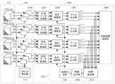
図17は、本実施形態に係る磁気センサアレイ210、センサデータ収集部230、およびセンサデータ処理部1700の構成を示す。 FIG. 17 shows the configurations of themagnetic sensor array 210, the sensordata collection unit 230, and the sensordata processing unit 1700 according to the present embodiment.

磁気センサアレイ210は、複数の磁気センサセル220を有する。複数の磁気センサセル220のそれぞれは、上述のとおり複数のセンサ部300x〜zを有してよい。本図においては、磁気センサアレイ210が各次元方向に有する複数の磁気センサセル220のうち、位置[i,j,k]、[i+1,j,k]、[i,j+1,k]、および、[i,j,k+1]に関する部分を示す。 Themagnetic sensor array 210 has a plurality ofmagnetic sensor cells 220. Each of the plurality ofmagnetic sensor cells 220 may have a plurality ofsensor units 300x to z as described above. In this figure, among the plurality ofmagnetic sensor cells 220 that themagnetic sensor array 210 has in each dimensional direction, the positions [i, j, k], [i + 1, j, k], [i, j + 1, k], and The part related to [i, j, k + 1] is shown.

センサデータ収集部230は、複数のAD変換器1710およびクロック発生器1712を有する。複数のAD変換器1710は、磁気センサセル220の複数のセンサ部300x〜zのそれぞれに対応して設けられており、対応するセンサ部300が出力するアナログの検出信号(図6のセンサ出力信号V_xMR)をデジタルの計測データV(Vx,Vy,Vz)に変換する。ここで、Vx、Vy、およびVzは、センサ部300x、300y、および300zからの検出信号をデジタルに変換した計測値(例えばデジタルの電圧値)である。 The sensordata acquisition unit 230 has a plurality ofAD converters 1710 and aclock generator 1712. The plurality ofAD converters 1710 are provided corresponding to each of the plurality ofsensor units 300x to z of themagnetic sensor cell 220, and the analog detection signal (sensor output signal V_xMR in FIG. 6) output by the correspondingsensor unit 300 is provided. ) Is converted into digital measurement data V (Vx, Vy, Vz). Here, Vx, Vy, and Vz are measured values (for example, digital voltage values) obtained by converting the detection signals from thesensor units 300x, 300y, and 300z into digital.

クロック発生器1712は、サンプリングクロックを発生させ、共通のサンプリングクロックを複数のAD変換器1710のそれぞれへ供給する。そして、複数のAD変換器1710のそれぞれは、クロック発生器1712から供給された共通のサンプリングクロックに応じてAD変換を行う。したがって、異なる位置に設けられた3軸のセンサ部300x〜zの出力をそれぞれAD変換する複数のAD変換器1710の全てが同期動作をする。これにより、複数のAD変換器1710は、異なる空間に設けられた3軸のセンサ部300x〜zの検出結果を同時にサンプリングすることができる。 Theclock generator 1712 generates a sampling clock and supplies a common sampling clock to each of the plurality ofAD converters 1710. Then, each of the plurality ofAD converters 1710 performs AD conversion according to the common sampling clock supplied from theclock generator 1712. Therefore, all of the plurality ofAD converters 1710 that AD-convert the outputs of the three-axis sensor units 300x to z provided at different positions perform synchronous operation. As a result, the plurality ofAD converters 1710 can simultaneously sample the detection results of the three-axis sensor units 300x to z provided in different spaces.

センサデータ処理部1700は、複数の磁気センサセル220のそれぞれに対応して設けられた複数の計測データ取得部1720、および、計測データ演算部1721を有する。計測データ演算部1721は、複数の較正演算部1730、複数のデータ出力部1740、基底ベクトル記憶部1750、信号空間分離部1760、指標算出部1770、指標出力部1780、および、故障判定部1790を有する。 The sensordata processing unit 1700 includes a plurality of measurementdata acquisition units 1720 and a measurementdata calculation unit 1721 provided corresponding to each of the plurality ofmagnetic sensor cells 220. The measurementdata calculation unit 1721 includes a plurality ofcalibration calculation units 1730, a plurality ofdata output units 1740, a basisvector storage unit 1750, a signalspace separation unit 1760, anindex calculation unit 1770, anindex output unit 1780, and afailure determination unit 1790. Have.

計測データ取得部1720は、測定対象磁場(例えば、心臓の電気活動により発生する心磁)を含む入力磁場に基づく計測データを取得する。計測データ取得部1720は、それぞれ対応する磁気センサセル220に接続された3つのAD変換器1710に接続され、磁気センサアレイ210を構成する複数の磁気センサセル220内のセンサ部300x〜zによって計測された計測データをそれぞれ取得する。具体的に、計測データ取得部1720は、AD変換器1710によってデジタルに変換された計測データV(Vx,Vy,Vz)を所定のタイミングTでラッチするフリップフロップ等を用いて構成されてよい。 The measurementdata acquisition unit 1720 acquires measurement data based on an input magnetic field including a magnetic field to be measured (for example, a magnetic field generated by the electrical activity of the heart). The measurementdata acquisition unit 1720 is connected to threeAD converters 1710 connected to the correspondingmagnetic sensor cells 220, and is measured by thesensor units 300x to z in the plurality ofmagnetic sensor cells 220 constituting themagnetic sensor array 210. Acquire each measurement data. Specifically, the measurementdata acquisition unit 1720 may be configured by using a flip-flop or the like that latches the measurement data V (Vx, Vy, Vz) digitally converted by theAD converter 1710 at a predetermined timing T.

計測データ演算部1721は、計測データ取得部1720が取得した計測データを較正する。例えば、較正演算部1730は、計測データ取得部1720に接続され、計測データ取得部1720が取得した計測データを、較正パラメータを用いて較正する。較正演算部1730による計測データの較正の概要は以下のとおりである。位置[i,j,k]にある磁気センサセル220に入力される磁場をB(B,B,B)とし、センサ部300x、300y、300zによる3軸磁気センサの検出結果を計測データV(Vx,Vy,Vz)とする。この場合、3軸磁気センサの磁気センサ特性を3軸センサ磁気感度行列Sとすると、3軸磁気センサの検出結果Vは次式のように示すことができる。

Figure 0006936405
The measurementdata calculation unit 1721 calibrates the measurement data acquired by the measurementdata acquisition unit 1720. For example, thecalibration calculation unit 1730 is connected to the measurementdata acquisition unit 1720 and calibrates the measurement data acquired by the measurementdata acquisition unit 1720 using the calibration parameters. The outline of calibration of the measurement data by thecalibration calculation unit 1730 is as follows. Position [i, j, k] to amagnetic sensor cell 220 magnetic fieldB to be inputted to the (Bx, B y,B z) and to thesensor unit 300x, 300y, detection result measurement data triaxial magnetic sensor by 300z Let it be V (Vx, Vy, Vz). In this case, assuming that the magnetic sensor characteristics of the 3-axis magnetic sensor are the 3-axis sensor magnetic sensitivity matrix S, the detection result V of the 3-axis magnetic sensor can be shown by the following equation.
Figure 0006936405

ここで、Sxx、Syy、Szzは、それぞれセンサ部300x、300y、300zの主軸方向の感度を表し、Sxy、Sxz、Syx、Syz、Szx、Szyは他軸方向の感度を表している。また、Vos,x、Vos,y、Vos,zは、それぞれセンサ部300x、300y、300zの主軸方向のオフセットを表している。 Here, Sxx, Syy, and Szz represent the sensitivities of thesensor units 300x, 300y, and 300z in the main axis direction, and Sxy, Sxz, Six, Syz, Szx, and Szy represent the sensitivities in the other axis direction. Further, Vos, x, Vos, y, Vos, and z represent offsets of thesensor units 300x, 300y, and 300z in the main axis direction, respectively.

センサ部300のそれぞれが、検出すべき入力磁場の範囲において、当該入力磁場に対する検出結果が線形性を有するので、3軸センサ磁気感度行列Sの各要素は、入力磁場Bの大きさとは無関係な略一定の係数となる。また、センサ部300が他軸感度を有していても、当該センサ部300の検出結果が線形性を有していれば、3軸センサ磁気感度行列Sの各要素は、入力磁場Bの大きさとは無関係な略一定の係数となる。 Since each of thesensor units 300 has linearity in the detection result for the input magnetic field in the range of the input magnetic field to be detected, each element of the 3-axis sensor magnetic sensitivity matrix S has nothing to do with the magnitude of the input magnetic field B. It is a substantially constant coefficient. Further, even if thesensor unit 300 has other-axis sensitivity, if the detection result of thesensor unit 300 has linearity, each element of the 3-axis sensor magnetic sensitivity matrix S has a large input magnetic field B. It is a substantially constant coefficient that has nothing to do with.

したがって、較正演算部1730は、3軸センサ磁気感度行列Sの逆行列S−1とオフセット(Vos,x,Vos,y,Vos,z)とを用いることで、次式のように、計測データV(Vx,Vy,Vz)を元の入力された磁場を示す磁場計測データB(B,B,B)に変換することができる。なお、この変換は、センサ部300x〜zが上述の磁気収束板を備えている場合も成立する。これは、磁気センサセル220がセンサ部300x〜zを利用した3軸磁気センサとして構成されるためであり、線形代数を利用した変換が可能となるからである。

Figure 0006936405
Therefore, thecalibration calculation unit 1730 uses the inverse matrix S-1 of the 3-axis sensor magnetic sensitivity matrix S and the offset (Vos, x, Vos, y, Vos, z) to measure the measurement data as shown in the following equation. V (Vx, Vy, Vz) can be converted field indicating the original input field measurement dataB (B x, B y, B z) to. It should be noted that this conversion is also established when thesensor units 300x to z are provided with the above-mentioned magnetic focusing plate. This is because themagnetic sensor cell 220 is configured as a three-axis magnetic sensor using thesensor units 300x to z, and conversion using linear algebra is possible.
Figure 0006936405

較正演算部1730は、環境磁場計測データを用いて3軸センサ磁気感度行列Sの逆行列S−1およびオフセット(Vos,x,Vos,y,Vos,z)を算出し、計測データ取得部1720により取得された計測データVを、これらの較正パラメータを用いて磁場計測データBに変換してデータ出力部1740に供給する。 Thecalibration calculation unit 1730 calculates the inverse matrix S-1 and the offset (Vos, x, Vos, y, Vos, z) of the 3-axis sensor magnetic sensitivity matrix S using the environmental magnetic field measurement data, and the measurementdata acquisition unit 1720. The measurement data V acquired by the above is converted into magnetic field measurement data B using these calibration parameters and supplied to thedata output unit 1740.

以上のように、各センサ部300が線形性を有するので、較正演算部1730は、略一定の係数を用いて計測データVを磁場計測データBに変換することができる。すなわち、較正演算部1730が用いる略一定の係数は、環境磁場データを用いて一組の較正パラメータとして定めることができる。 As described above, since eachsensor unit 300 has linearity, thecalibration calculation unit 1730 can convert the measurement data V into the magnetic field measurement data B using a substantially constant coefficient. That is, the substantially constant coefficient used by thecalibration calculation unit 1730 can be determined as a set of calibration parameters using the environmental magnetic field data.

データ出力部1740は、較正演算部1730によって較正された磁場計測データBを信号空間分離部1760に供給する。 Thedata output unit 1740 supplies the magnetic field measurement data B calibrated by thecalibration calculation unit 1730 to the signalspace separation unit 1760.

基底ベクトル記憶部1750は、信号空間分離部1760が磁場計測データBを信号分離するために必要な基底ベクトルを予め記憶し、これを信号空間分離部1760へ供給する。 The basisvector storage unit 1750 stores in advance the basis vector required for the signalspace separation unit 1760 to signal-separate the magnetic field measurement data B, and supplies this to the signalspace separation unit 1760.

信号空間分離部1760は、計測データVから生成した磁場計測データB、例えば、較正演算部1730が計測データVを較正して生成した磁場計測データBによって示される入力磁場の空間分布を、正規直交関数の空間分布を持つ磁場を磁気センサアレイ210で検出したときに磁気センサ520のそれぞれが出力する信号ベクトルを基底ベクトルとして信号分離する。この際、信号空間分離部1760は、信号分離に必要な基底ベクトルを、基底ベクトル記憶部1750から取得する。そして、信号空間分離部1760は、基底ベクトル記憶部1750から取得した基底ベクトルを用いて、磁場計測データBによって示される磁場の空間分布を、測定対象磁場である心磁と外乱磁場とに信号分離し、外乱磁場を抑制して心磁を算出し、これを出力する。 The signalspace separation unit 1760 performs a normal orthogonality with respect to the magnetic field measurement data B generated from the measurement data V, for example, the spatial distribution of the input magnetic field indicated by the magnetic field measurement data B generated by thecalibration calculation unit 1730 calibrating the measurement data V. When the magnetic field having the spatial distribution of the function is detected by themagnetic sensor array 210, the signal vectors output by each of themagnetic sensors 520 are used as the base vector to separate the signals. At this time, the signalspace separation unit 1760 acquires the basis vector required for signal separation from the basisvector storage unit 1750. Then, the signalspace separation unit 1760 uses the base vector acquired from the basevector storage unit 1750 to separate the spatial distribution of the magnetic field indicated by the magnetic field measurement data B into the magnetic field to be measured and the disturbance magnetic field. Then, the disturbance magnetic field is suppressed, the core magnetism is calculated, and this is output.

指標算出部1770は、計測データ演算部1721、例えば、較正演算部1730における較正の精度を示す指標εを算出する。指標算出部1770は、信号空間分離部1760に接続され、信号空間分離部1760が信号分離した結果に基づいて、指標εを算出する。これについては後述する。 Theindex calculation unit 1770 calculates an index ε indicating the accuracy of calibration in the measurementdata calculation unit 1721, for example, thecalibration calculation unit 1730. Theindex calculation unit 1770 is connected to the signalspace separation unit 1760, and calculates the index ε based on the result of signal separation by the signalspace separation unit 1760. This will be described later.

指標出力部1780は、指標算出部1770に接続され、指標算出部1770が算出した指標εを出力する。この際、指標出力部1780は、例えば、指標εを表示部に表示させてもよいし、指標εをネットワークを介して他の装置に供給してもよい。また、指標出力部1780は、本図に示すように、指標εを故障判定部1790に供給する。 Theindex output unit 1780 is connected to theindex calculation unit 1770 and outputs the index ε calculated by theindex calculation unit 1770. At this time, theindex output unit 1780 may display the index ε on the display unit, or may supply the index ε to another device via the network, for example. Further, theindex output unit 1780 supplies the index ε to thefailure determination unit 1790 as shown in this figure.

故障判定部1790は、指標算出部1770が算出した指標εに基づいて、心磁計測装置10の故障を判定する。 Thefailure determination unit 1790 determines the failure of themagnetocardiographic measuring device 10 based on the index ε calculated by theindex calculation unit 1770.

図18は、本実施形態に係る心磁計測装置10が磁場の空間分布を信号分離するフローを示す。ステップ1810において、基底ベクトル記憶部1750は、基底ベクトルを記憶する。一例として、基底ベクトル記憶部1750は、心磁の計測前に、球面調和関数の空間分布を持つ磁場を磁気センサアレイ210で検出したときに複数の磁気センサ520のそれぞれが出力する信号ベクトルを基底ベクトルとして記憶する。すなわち、基底ベクトル記憶部1750は、空間内の予め定められた点を座標原点に指定した時に球面調和関数を空間サンプリングして得られる磁場信号ベクトルを基底ベクトルとして記憶する。ここで、球面調和関数とは、n次元ラプラス方程式の解となる斉次多項式を単位球面に制限することで得られる関数であり、球面上での正規直交性を有する。なお、本図においては、一例として、基底ベクトル記憶部1750が基底ベクトルを記憶するステップ1810を、心磁計測装置10による磁場の空間分布を信号分離するフローにおける最初のステップとした場合について示す。しかしながら、基底ベクトル記憶部1750は、心磁計測装置10による磁場の空間分布を信号分離するフローの前に、基底ベクトルを事前に記憶しておいてもよい。また、基底ベクトル記憶部1750は、シミュレーション結果等により予め決められている信号ベクトルを基底ベクトルとして記憶してもよい。 FIG. 18 shows a flow in which themagnetocardiographic measuring device 10 according to the present embodiment signals separates the spatial distribution of the magnetic field. In step 1810, the basisvector storage unit 1750 stores the basis vector. As an example, the basevector storage unit 1750 bases a signal vector output by each of a plurality ofmagnetic sensors 520 when a magnetic field having a spatial distribution of spherical harmonics is detected by themagnetic sensor array 210 before measuring the magnetic field. Store as a vector. That is, the basevector storage unit 1750 stores the magnetic field signal vector obtained by spatially sampling the spherical harmonics when a predetermined point in space is designated as the coordinate origin as the base vector. Here, the spherical harmonics is a function obtained by limiting the homogeneous polynomial that is the solution of the n-dimensional Laplace's equation to the unit sphere, and has normal orthogonality on the sphere. In this figure, as an example, a case where step 1810 in which the basisvector storage unit 1750 stores the basis vector is set as the first step in the flow of signal separation of the spatial distribution of the magnetic field by themagnetocardiographic measuring device 10 is shown. However, the basisvector storage unit 1750 may store the basis vector in advance before the flow of signal-separating the spatial distribution of the magnetic field by themagnetocardiographic measuring device 10. Further, the basisvector storage unit 1750 may store a signal vector predetermined based on a simulation result or the like as a basis vector.

次に、ステップ1820において、信号空間分離部1760は、磁気センサアレイ210によって計測され、較正演算部1730によって較正された磁場計測データBを、データ出力部1740から取得する。 Next, instep 1820, the signalspace separation unit 1760 acquires the magnetic field measurement data B measured by themagnetic sensor array 210 and calibrated by thecalibration calculation unit 1730 from thedata output unit 1740.

また、ステップ1830において、信号空間分離部1760は、ステップ1810において基底ベクトル記憶部1750が基底ベクトルとして記憶した信号ベクトルを、基底ベクトル記憶部1750から取得する。なお、本フローにおいて、ステップ1820とステップ1830とはどちらが先に行われてもよい。 Further, instep 1830, the signalspace separation unit 1760 acquires the signal vector stored as the basis vector by the basisvector storage unit 1750 in step 1810 from the basisvector storage unit 1750. In this flow, eitherstep 1820 orstep 1830 may be performed first.

ステップ1840において、信号空間分離部1760は、ステップ1820において取得した磁場計測データBによって示される磁場の空間分布を、ステップ1830において取得した信号ベクトルを基底ベクトルとして利用して級数展開する。そして、信号空間分離部1760は、級数展開によって得られたベクトルから、磁場の空間分布を測定対象磁場と外乱磁場とに信号分離する。なお、正規直交関数は球面調和関数であってよい。また、信号空間分離部1760は、信号分離するにあたって、基底ベクトルの係数を最小2乗法により計算する。 Instep 1840, the signalspace separation unit 1760 expands the spatial distribution of the magnetic field indicated by the magnetic field measurement data B acquired instep 1820 into a series using the signal vector acquired instep 1830 as a base vector. Then, the signalspace separation unit 1760 separates the spatial distribution of the magnetic field into the measurement target magnetic field and the disturbance magnetic field from the vector obtained by the series expansion. The orthonormal function may be a spherical harmonic function. Further, the signalspace separation unit 1760 calculates the coefficient of the basis vector by the method of least squares when separating signals.

そして、ステップ1850において、信号空間分離部1760は、ステップ1840において信号分離した結果に基づいて、外乱磁場を抑制して測定対象磁場である心磁だけを算出して出力し、処理を終了する。以下、これについて詳細に説明する。 Then, in step 1850, the signalspace separation unit 1760 suppresses the disturbance magnetic field, calculates and outputs only the magnetocardiography which is the measurement target magnetic field, based on the result of signal separation instep 1840, and ends the process. This will be described in detail below.

静磁場B(r)は、ラプラス方程式Δ・V(r)=0を満たすポテンシャルV(r)を用いて、次式のように、ポテンシャルV(r)の空間勾配(gradient)として求められる。ここで、rは座標原点からの位置を表す位置ベクトルであり、Δはラプラシアンであり、μは透磁率であり、∇はベクトル微分演算を表す演算子である。

Figure 0006936405
The static magnetic field B (r) is obtained as a gradient of the potential V (r) by using the potential V (r) satisfying Laplace's equation Δ · V (r) = 0 as shown in the following equation. Here, r is a position vector representing the position from the coordinate origin, Δ is Laplacian, μ is the magnetic permeability, and ∇ is an operator representing a vector differential operation.
Figure 0006936405

そして、ラプラス方程式の解は、一般に、正規直交関数系である球面調和関数Yl,m(θ,φ)を使った級数展開の形での解を持つため、ポテンシャルV(r)は次式で表すことができる。ここで、|r|は位置ベクトルrの絶対値(座標原点からの距離)であり、θおよびφは球座標における2つの偏角であり、lは方位量子数であり、mは磁気量子数であり、αおよびβは多極モーメントであり、LinおよびLoutはそれぞれ被験者から見て磁気センサアレイ210の手前の空間と奥の空間のそれぞれについての級数の数である。方位量子数lは正の整数をとり、磁気量子数mは−lから+lまでの整数をとる。すなわち、例えばlが1のとき、mは−1、0、および1であり、例えばlが2のとき、mは−2、−1、0、1、および2である。なお、磁場においては単磁極が存在しないことから、(数7)において方位量子数lは、0からではなく1から始まっている。(数7)における第1項は、座標原点からの距離に反比例する項であり、被験者から見て磁気センサアレイ210の手前の空間に存在するポテンシャルを示している。また、(数7)における第2項は、座標原点からの距離に比例する項であり、被験者から見て磁気センサアレイ210の奥の空間に存在するポテンシャルを示している。

Figure 0006936405
Since the solution of Laplace's equation generallyhas a solution in the form of series expansion using the spherical harmonics Y l, m (θ, φ), which is a normal orthogonal function system, the potential V (r) is given by the following equation. Can be represented by. Here, | r | is the absolute value of the position vector r (distance from the coordinate origin), θ and φ are two deviation angles in spherical coordinates, l is the azimuthal quantum number, and m is the magnetic quantum number. Α and β are multipolar moments, and Lin and Lout are the number of coordinates for the space in front of themagnetic sensor array 210 and the space in the back, respectively, as seen from the subject. The azimuthal quantum number l takes a positive integer, and the magnetic quantum number m takes an integer from −l to + l. That is, for example, when l is 1, m is -1, 0, and 1, and when l is 2, for example, m is -2, -1, 0, 1, and 2. Since there is no monopole in the magnetic field, the azimuthal quantum number l starts from 1 instead of 0 in (Equation 7). The first term in (Equation 7) is a term that is inversely proportional to the distance from the coordinate origin, and indicates the potential existing in the space in front of themagnetic sensor array 210 when viewed from the subject. The second term in (Equation 7) is a term proportional to the distance from the coordinate origin, and indicates the potential existing in the space behind themagnetic sensor array 210 when viewed from the subject.
Figure 0006936405

したがって、(数6)および(数7)によれば、静磁場B(r)は、次式で表すことができる。ここで、(数8)における第1項は、被験者から見て磁気センサアレイ210の手前の空間に存在する磁場源、すなわち、心臓の電気活動が作る心磁(測定対象磁場)を示している。また、(数8)における第2項は、被験者から見て磁気センサアレイ210の奥の空間に存在する磁場源が作る外乱磁場を示している。

Figure 0006936405
Therefore, according to (Equation 6) and (Equation 7), the static magnetic field B (r) can be expressed by the following equation. Here, the first term in (Equation 8) indicates a magnetic field source existing in the space in front of themagnetic sensor array 210 when viewed from the subject, that is, a magnetocardiography (magnetic field to be measured) created by the electrical activity of the heart. .. Further, the second term in (Equation 8) indicates a disturbance magnetic field created by a magnetic field source existing in the space behind themagnetic sensor array 210 when viewed from the subject.
Figure 0006936405

球面調和関数を使った級数展開の形でラプラス方程式の解を表した場合、その一般解は無限級数となるが、生体磁場を計測するのに十分なSNR(信号ノイズ比、すなわち、外乱磁場及びセンサノイズに対する測定対象磁場信号の比)が得られればよく、実際には10項程度の級数で表せば十分であると言われている。また、脳磁計における信号空間分離の級数については、Lin=8、Lout=3程度でよいと言われている。したがって、本実施形態においても、Lin=8、Lout=3の場合を一例として説明する。しかしながら、LinおよびLoutの値は、これに限定されるものではなく、外乱磁場を十分抑制し測定対象磁場だけを算出するのに十分な、いかなる数値であってもよい。 When the solution of the Laplace equation is expressed in the form of a series expansion using spherical harmonics, the general solution is an infinite series, but the SNR (signal-to-noise ratio, that is, the disturbance magnetic field and It suffices if the ratio of the magnetic field signal to be measured to the sensor noise) can be obtained, and it is said that it is actually sufficient to express it in a series of about 10 terms. Further, it is said that the series of signal space separation in the magnetoencephalograph may be about Lin = 8 and Lout = 3. Therefore, also in this embodiment, the case of Lin = 8 and Lout = 3 will be described as an example. However, the values of Lin and Lout are not limited to this, and may be any numerical value sufficient to sufficiently suppress the disturbance magnetic field and calculate only the magnetic field to be measured.

ここで、各磁気センサセル220におけるセンサ部300x、y、およびzの感磁軸方向と磁気感度を表すベクトルを、それぞれ、nx、ny、およびnzとし、添字tを転置行列として、al,mおよびbl,mを次式のように定義する。すなわち、al,mおよびbl,mを、センサ部300x、y、およびzの感磁軸方向と磁気感度を表す各ベクトル)nx、ny、nzと、三次元のベクトル信号である球面調和関数との内積を成分として有するベクトルとして定義する。これは、各磁気センサセル220において、球面調和関数を直交座標系でサンプリングすることを意味している。なお、このal,mおよびbl,mは磁気センサセル220の個数を3倍した数の次元を持つベクトルとなる。また、各センサ部300の感磁軸方向と磁気感度を表す各ベクトルnx、ny、nzは、先述した主軸方向の感度、および、他軸方向の感度と対応したベクトルでよい。nxは、Sxx、Sxy、Sxzに対応してよい。nyは、Syx、Syy、Syzに対応してよい。nzは、Szx、Szy、Szzに対応してよい。例えば、図29に示す変形例のように、計測データ演算部1721は、較正演算部1730に代えて、基底ベクトル較正部1771を有してもよい。このような構成において、基底ベクトル較正部1771は、指標算出部1770によって算出された指標εに基づいて、センサ部300x、y、およびzの主軸方向の感度と他軸方向の感度補正を含めてal,mおよびbl,mを計算することによって基底ベクトルを較正し、基底ベクトル記憶部1750は、較正された基底ベクトルであるal,mおよびbl,mを記憶する。本変形例に係る心磁計測装置10の信号空間分離部1760は、動作時に、基底ベクトル記憶部1750に記憶されている、較正された基底ベクトルであるal,mおよびbl,mを用いて、上述したように、磁場計測データBによって示される磁場の空間分布を、測定対象磁場である心磁と外乱磁場とに信号分離し、外乱磁場を抑制して心磁を算出し、これを出力する。このようにして算出された心磁は、各磁気センサセル220の磁気感度(主軸感度、他軸感度)の補正が行われている。

Figure 0006936405
Here, the vectors representing the magnetic sensitivity axes and the magnetic sensitivities of thesensor units 300x, y, and z in eachmagnetic sensor cell 220 are set to nx, ny, and nz, respectively, and the subscript t is used as a transposed matrix, all, m. Andbl and m are defined as follows. That is, al, m andbl, m are vector harmonized with nx, ny, nz, which are three-dimensional vector signals, with each vector representing the magnetic sensitivity axis direction and magnetic sensitivity of thesensor units 300x, y, and z. It is defined as a vector having an inner product with a function as a component. This means that in eachmagnetic sensor cell 220, the spherical harmonics are sampled in a Cartesian coordinate system. Note that these al, m and bl, m are vectors having dimensions obtained by multiplying the number ofmagnetic sensor cells 220 by three. Further, the vectors nx, ny, and nz representing the magnetic sensitivity axis direction and the magnetic sensitivity of eachsensor unit 300 may be vectors corresponding to the above-mentioned sensitivity in the main axis direction and the sensitivity in the other axis direction. nx may correspond to Sxx, Sxy, Sxx. ny may correspond to Syx, Syy, and Syz. nz may correspond to Szx, Szy, Szz. For example, as in the modified example shown in FIG. 29, the measurementdata calculation unit 1721 may have a basisvector calibration unit 1771 instead of thecalibration calculation unit 1730. In such a configuration, the basisvector calibration unit 1771 includes the sensitivity of thesensor units 300x, y, and z in the main axis direction and the sensitivity correction in the other axis direction based on the index ε calculated by theindex calculation unit 1770. Thebasis vector is calibrated by calculating a l, m and bl, m , and the basisvector storage unit 1750 stores the calibrated basis vectors al, m and bl, m . The signalspace separation unit 1760 of the magneticfield measuring device 10 according to this modification uses the calibrated base vectors al, m and bl, m stored in the base vector storage unit 1750 during operation. As described above, the spatial distribution of the magnetic field indicated by the magnetic field measurement data B is signal-separated into the magnetic field to be measured and the disturbance magnetic field, the disturbance magnetic field is suppressed, and the magnetic field is calculated. Output. The magnetocardiography calculated in this way is corrected for the magnetic sensitivity (main axis sensitivity, other axis sensitivity) of eachmagnetic sensor cell 220.
Figure 0006936405

そうすると、ある時刻にそれぞれの磁気センサセル220において出力されるセンサ出力ベクトルΦは、以下の式で表すことができる。

Figure 0006936405
Then, the sensor output vector Φ output in eachmagnetic sensor cell 220 at a certain time can be expressed by the following equation.
Figure 0006936405

さらに、Sin、Sout、Xin、およびXoutをそれぞれ次のように定義する。すなわち、Sinを、l=1からl=Linまで、各lにおいてm=−lからlまでの整数をとった時の各ベクトルaを順に列に並べた、計Lin・(Lin+2)列のベクトルと定義する。また、Soutを、l=1からL=Loutまで、各lにおいてm=−lからlまでの整数をとった時の各ベクトルbを順に列に並べた、計Lout・(Lout+2)列のベクトルと定義する。また、Xinを、l=1からl=Linまで、各lにおいてm=−lからlまでの整数をとった時の各多極モーメントαを順に列に並べたベクトルを転置した、計Lin・(Lin+2)行のベクトルと定義する。また、Xoutを、l=1からl=Linまで、各lにおいてm=−1からlまでの整数をとった時の各多極モーメントβを順に列に並べたベクトルを転置した、計Lout・(Lout+2)行のベクトルと定義する。

Figure 0006936405
Further, Sin, Sout, Xin, and Xout are defined as follows. That is, the vectors of the total Lin · (Lin + 2) column in which the vectors a when Sin is taken as an integer from l = 1 to l = Lin and m = −l to l in each l are arranged in order. Is defined as. Further, Sout is a vector of a total Lout · (Lout + 2) column in which each vector b when an integer from m = −l to l is taken in each l from l = 1 to L = Lout is arranged in a column in order. Is defined as. Further, Xin is transposed from a vector in which each multipolar moment α when an integer from m = −l to l is taken in each l from l = 1 to l = Lin is transposed. It is defined as a vector of (Lin + 2) rows. Further, Xout is transposed from a vector in which each multipolar moment β when an integer from m = -1 to l is taken in order from l = 1 to l = Lin, and each l is transposed. It is defined as a vector of (Lout + 2) rows.
Figure 0006936405

そうすると、センサ出力ベクトルΦは、次式に示すように、基底ベクトル行列Sと縦ベクトルXの内積の形で表すことができる。ここで、基底ベクトル行列Sは、基底ベクトルを示し、例えば、ステップ1830において、信号空間分離部1760が基底ベクトル記憶部1750から取得したものである。また、縦ベクトルXは、基底ベクトルに係る係数を示す。

Figure 0006936405
Then, the sensor output vector Φ can be expressed in the form of the inner product of the basis vector matrix S and the vertical vector X as shown in the following equation. Here, the basis vector matrix S indicates a basis vector, and is obtained by the signalspace separation unit 1760 from the basisvector storage unit 1750 instep 1830, for example. Further, the vertical vector X indicates a coefficient related to the basis vector.
Figure 0006936405

本実施形態に係る信号空間分離部1760は、ステップ1840において、この(数12)で得られたセンサ出力ベクトルΦのモデル式に基づいて、次式を用いてΦ=S・Xを最小2乗近似で満たす縦ベクトル^X(ここで、「^X」は、(数13)における左辺を示し、Xのハット(推定値)を意味するものとする。)を決定する。これにより、信号空間分離部1760は、ステップ1840において、磁場の空間分布を解くことができる。この際、信号空間分離部1760は、外乱磁場の大きさが予め定められた範囲を超える場合に、測定対象磁場である心磁を高精度に計測できない旨の警告を出してもよい。これにより、心磁計測装置10は、装置が故障している場合や、測定対象磁場を高精度に計測することができない程大きな外乱磁場が存在している場合等の状況において、心磁を計測してしまうことを事前に防止することができる。この場合に、信号空間分離部1760は、例えば、^Xout・Soutの各成分のいずれかの大きさが予め定められた閾値を超える場合に外乱磁場の大きさが予め定められた範囲を超えると判断してもよいし、^Xout・Soutの各成分の大きさの和や平均が予め定められた閾値を超える場合に外乱磁場の大きさが予め定められた範囲を超えると判断してもよい。

Figure 0006936405
Instep 1840, the signalspace separation unit 1760 according to the present embodiment sets Φ = SX to the minimum square using the following equation based on the model equation of the sensor output vector Φ obtained in this (Equation 12). The vertical vector ^ X to be satisfied by the approximation (here, “^ X” indicates the left side in (Equation 13) and means the hat (estimated value) of X) is determined. As a result, the signalspace separation unit 1760 can solve the spatial distribution of the magnetic field instep 1840. At this time, the signalspace separation unit 1760 may issue a warning that the magnetocardiography, which is the magnetic field to be measured, cannot be measured with high accuracy when the magnitude of the disturbance magnetic field exceeds a predetermined range. As a result, themagnetocardiographic measuring device 10 measures the magnetocardiography in situations such as when the device is out of order or when there is a disturbing magnetic field that is too large to measure the magnetic field to be measured with high accuracy. It is possible to prevent this from happening in advance. In this case, the signalspace separation unit 1760 determines that, for example, when the magnitude of any of the components of ^ Xout and Sout exceeds a predetermined threshold value, the magnitude of the disturbance magnetic field exceeds a predetermined range. It may be determined that the magnitude of the disturbance magnetic field exceeds a predetermined range when the sum or average of the sizes of the components of ^ Xout and Sout exceeds a predetermined threshold value. ..
Figure 0006936405

そして、ステップ1850において、信号空間分離部1760は、ステップ1840において決定した縦ベクトルを用いて、^Xout・Soutを減少させて外乱磁場成分、すなわち、(数8)における第2項の成分を抑制した結果を出力する。信号空間分離部1760は、^Xin・Sinだけを結果として出力することで、外乱磁場成分を抑制して、測定対象磁場である心磁成分、すなわち、(数8)における第1項の成分だけを出力してもよい。 Then, in step 1850, the signalspace separation unit 1760 uses the vertical vector determined instep 1840 to reduce ^ Xout · Sout and suppress the disturbance magnetic field component, that is, the component of the second term in (Equation 8). Output the result. The signalspace separation unit 1760 suppresses the disturbance magnetic field component by outputting only ^ Xin / Sin as a result, and suppresses the magnetocardiographic component which is the magnetic field to be measured, that is, only the component of the first term in (Equation 8). May be output.

これにより、本実施形態に係る心磁計測装置10によれば、複数の磁気センサセル220を有し、三次元空間内の複数の箇所において3軸方向の入力磁場を検出可能な磁気センサアレイ210を用いて計測された磁場計測データBによって示される磁場の空間分布を、測定対象磁場である心磁と外乱磁場とに信号分離することができる。また、心磁計測装置10は、外乱磁場成分を抑制して心磁成分だけを出力するので、心磁をより高精度に計測することができる。また、複数のセンサ部300がそれぞれ磁気収束板を有するので、センサ部300の磁気感度を高めるとともに、空間サンプリング点を明確化することができ、信号空間分離技術との親和性をより高めることができる。さらに、心磁計測装置10が較正演算部1730を有する場合には、高精度な較正(主軸感度ミスマッチ、他軸感度、およびオフセット等)を実現でき、複数のセンサ部300のキャリブレーション誤差を、信号空間分離段階で処理するのではなく、その前段で低減させることができるので、より高精度に測定対象磁場成分を取り出すことができる。 As a result, according to themagnetic measurement device 10 according to the present embodiment, themagnetic sensor array 210 having a plurality ofmagnetic sensor cells 220 and capable of detecting an input magnetic field in the three axial directions at a plurality of locations in the three-dimensional space. The spatial distribution of the magnetic field indicated by the magnetic field measurement data B measured using the magnetism can be signal-separated into the magnetic field to be measured and the disturbance magnetic field. Further, since themagnetocardiographic measuring device 10 suppresses the disturbance magnetic field component and outputs only the magnetocardiographic component, the magnetocardiography can be measured with higher accuracy. Further, since each of the plurality ofsensor units 300 has a magnetic focusing plate, the magnetic sensitivity of thesensor unit 300 can be enhanced, the spatial sampling point can be clarified, and the affinity with the signal space separation technology can be further enhanced. can. Further, when the coremagnetic measuring device 10 has acalibration calculation unit 1730, highly accurate calibration (main axis sensitivity mismatch, other axis sensitivity, offset, etc.) can be realized, and calibration errors of a plurality ofsensor units 300 can be reduced. Since it can be reduced in the previous stage instead of being processed in the signal space separation stage, the magnetic field component to be measured can be extracted with higher accuracy.

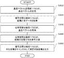
図19は、本実施形態に係る心磁計測装置10が、指標εを算出して指標εに基づいた制御を行うフローを示す。ステップ1910において、較正演算部1730は、上述の(数5)に基づいて、計測データVを較正して磁場計測データBを生成する。そして、較正演算部1730は、磁場計測データBをデータ出力部1740を介して信号空間分離部1760へ供給する。 FIG. 19 shows a flow in which themagnetocardiographic measuring device 10 according to the present embodiment calculates an index ε and performs control based on the index ε. Instep 1910, thecalibration calculation unit 1730 calibrates the measurement data V and generates the magnetic field measurement data B based on the above (Equation 5). Then, thecalibration calculation unit 1730 supplies the magnetic field measurement data B to the signalspace separation unit 1760 via thedata output unit 1740.

ステップ1920において、信号空間分離部1760は、磁場計測データBによって示される入力磁場の空間分布を、図18のフローに従って、信号分離する。そして、信号空間分離部1760は、信号分離した結果を指標算出部1770へ供給する。この際、信号空間分離部1760は、信号分離した結果として、例えば、センサ出力ベクトルΦ、基底ベクトル行列S、および、縦ベクトル^Xを指標算出部1770へ供給してよい。 Instep 1920, the signalspace separation unit 1760 separates the spatial distribution of the input magnetic field indicated by the magnetic field measurement data B according to the flow of FIG. Then, the signalspace separation unit 1760 supplies the signal separation result to theindex calculation unit 1770. At this time, the signalspace separation unit 1760 may supply, for example, the sensor output vector Φ, the basis vector matrix S, and the vertical vector ^ X to theindex calculation unit 1770 as a result of signal separation.

ステップ1930において、指標算出部1770は、信号空間分離部1760が信号分離した結果に基づいて、計測データ演算部1721、例えば、較正演算部1730における較正の精度を示す指標εを算出する。指標算出部1770は、例えば、次式に示すように、センサ出力ベクトルΦから、基底ベクトル行列Sと縦ベクトル^Xとの内積を減算して指標εを算出してよい。すなわち、指標算出部1770は、ある時刻にそれぞれの磁気センサセル220において出力されるセンサ出力ベクトルΦを、最小2乗法を用いて基底ベクトル行列S=[Sin,Sout]によって張られる部分空間へマッピングした際の誤差を、ベクトルの成分ごとに算出し、これを指標εとする。そして、指標算出部1770は、算出した指標εを指標出力部1780へ供給する。

Figure 0006936405
In step 1930, theindex calculation unit 1770 calculates an index ε indicating the accuracy of calibration in the measurementdata calculation unit 1721, for example, thecalibration calculation unit 1730, based on the result of signal separation by the signalspace separation unit 1760. Theindex calculation unit 1770 may calculate the index ε by subtracting the inner product of the basis vector matrix S and the vertical vector ^ X from the sensor output vector Φ, for example, as shown in the following equation. That is, theindex calculation unit 1770 maps the sensor output vector Φ output in eachmagnetic sensor cell 220 at a certain time to the subspace stretched by the basis vector matrix S = [Sin, Sout] using the least squares method. The error is calculated for each component of the vector, and this is used as the index ε. Then, theindex calculation unit 1770 supplies the calculated index ε to theindex output unit 1780.
Figure 0006936405

次に、指標出力部1780は、指標εを表示部に表示させる。そして、指標出力部1780は、指標εを故障判定部1790に供給する。この際、指標出力部1780はさらに、指標εをネットワークを介して他の装置に供給してもよい。 Next, theindex output unit 1780 causes the display unit to display the index ε. Then, theindex output unit 1780 supplies the index ε to thefailure determination unit 1790. At this time, theindex output unit 1780 may further supply the index ε to another device via the network.

ステップ1940において、故障判定部1790は、指標εが予め定められた基準の範囲内であるか否か判定する。故障判定部1790は、例えば、次式に示すように、指標の2乗が、予め定められた閾値E_Thの2乗未満であるか否か判定する。すなわち、故障判定部1790は、指標εのベクトルの大きさが予め定められた閾値E_th未満であるか否か判定する。

Figure 0006936405
Instep 1940, thefailure determination unit 1790 determines whether the index ε is within a predetermined reference range. Thefailure determination unit 1790 determines, for example, whether or not the square of the index is less than the square of the predetermined threshold value E_Th, as shown in the following equation. That is, thefailure determination unit 1790 determines whether or not the magnitude of the vector of the index ε is less than the predetermined threshold value E_th.
Figure 0006936405

ここで、指標εは、磁気センサアレイ210が有する複数の磁気センサセル220内に含まれるセンサ部300の数に対応するベクトルの成分からなる。故障判定部1790は、例えば、複数の成分ごとの指標を算出し、それらの平均が予め定められた基準の範囲内であるか否か判定してよい。これに代えて、故障判定部1790は、算出した複数の成分ごとの指標のうち、大きさが最大となる成分の指標、大きさが最小となる成分の指標、および、複数の成分の中央値のいずれかが予め定められた基準の範囲内であるか否か判定してもよい。 Here, the index ε is composed of a vector component corresponding to the number ofsensor units 300 included in the plurality ofmagnetic sensor cells 220 included in themagnetic sensor array 210. Thefailure determination unit 1790 may, for example, calculate an index for each of a plurality of components and determine whether or not the average thereof is within a predetermined reference range. Instead, thefailure determination unit 1790 determines the index of the component having the largest size, the index of the component having the smallest size, and the median value of the plurality of components among the calculated indexes for each of the plurality of components. It may be determined whether or not any of the above is within the range of a predetermined standard.

そして、故障判定部1790は、指標εが予め定められた基準の範囲内であると判定した場合、較正演算部1730において精度よく較正されたと判断して処理を終了する。すなわち、故障判定部1790は、較正演算部1730において精度よく較正されているので、心磁計測装置10の計測結果が、信頼性が高いものであると判断し、さらなる処理を要求しない。 Then, when thefailure determination unit 1790 determines that the index ε is within the range of the predetermined reference, thecalibration calculation unit 1730 determines that the calibration has been performed accurately and ends the process. That is, since thefailure determination unit 1790 is accurately calibrated by thecalibration calculation unit 1730, it is determined that the measurement result of themagnetocardiographic measurement device 10 is highly reliable, and no further processing is required.

一方、ステップ1940において、指標εが予め定められた基準の範囲内でないと判定した場合、故障判定部1790は、ステップ1950において、較正演算部1730における較正回数が予め定められた回数以内であるか否か判定する。 On the other hand, if it is determined instep 1940 that the index ε is not within the predetermined reference range, thefailure determination unit 1790 indicates whether the number of calibrations in thecalibration calculation unit 1730 is within the predetermined number of times instep 1950. Judge whether or not.

そして、較正回数が予め定められた回数以内でなかったと判定された場合、ステップ1960において、故障判定部1960は、心磁計測装置10に故障が生じているものと判定して処理を終了する。この際、故障判定部1960は、心磁計測装置10に故障が生じている旨を表示部に表示、または、音で報知してもよい。また、故障判定部1960は、ステップ1940において算出したベクトルの成分ごとの指標から、心磁計測装置10の故障箇所を推定して、それを出力してもよい。この際、故障判定部1960は、予め定められた基準の範囲内にないと判定された指標に対応する磁気センサセル220やセンサ部300を特定する情報を出力してよい。また、故障判定部1960は、例えば、ベクトルの成分ごとの指標を、対応する磁気センサセル220やセンサ部300にマッピングした指標マップを出力してもよい。 If it is determined that the number of calibrations is not within the predetermined number of times, instep 1960, thefailure determination unit 1960 determines that themagnetocardiographic measuring device 10 has a failure and ends the process. At this time, thefailure determination unit 1960 may display on the display unit that a failure has occurred in themagnetocardiographic measuring device 10 or notify by sound. Further, thefailure determination unit 1960 may estimate the failure location of themagnetocardiographic measuring device 10 from the index for each component of the vector calculated instep 1940 and output it. At this time, thefailure determination unit 1960 may output information for identifying themagnetic sensor cell 220 or thesensor unit 300 corresponding to the index determined not to be within the predetermined reference range. Further, thefailure determination unit 1960 may output, for example, an index map in which the index for each component of the vector is mapped to the correspondingmagnetic sensor cell 220 or thesensor unit 300.

一方、ステップ1950において、較正回数が予め定められた回数以内であると判定された場合、故障判定部は、較正演算部1730に対して、計測データを再較正する旨を指示する。そして、ステップ1970において、較正演算部1730は、較正パラメータを変更して、処理をステップ1910に戻し、変更された較正パラメータを用いて再較正を行い、処理を継続する。この際、較正演算部1730は、例えば、環境磁場の計測を再び行って、センサ部300の主軸感度、他軸感度、および、オフセットを再調整して較正パラメータを変更してもよい。 On the other hand, if it is determined instep 1950 that the number of calibrations is within a predetermined number of times, the failure determination unit instructs thecalibration calculation unit 1730 to recalibrate the measurement data. Then, instep 1970, thecalibration calculation unit 1730 changes the calibration parameter, returns the process to step 1910, recalibrates using the changed calibration parameter, and continues the process. At this time, thecalibration calculation unit 1730 may, for example, measure the environmental magnetic field again and readjust the spindle sensitivity, the other axis sensitivity, and the offset of thesensor unit 300 to change the calibration parameters.

なお、図19のフローは、被験者が心磁計測装置10の計測位置にいる場合に行われてもよいし、被験者が心磁計測装置10の計測位置に来る前に事前に行われてもよい。この場合、故障判定部は、被験者がいる場合といない場合とで、故障判定に用いる閾値E_Thを異なる値に設定してもよい。 The flow of FIG. 19 may be performed when the subject is at the measurement position of themagnetocardiographic measuring device 10, or may be performed in advance before the subject comes to the measuring position of themagnetocardiographic measuring device 10. .. In this case, the failure determination unit may set the threshold value E_Th used for the failure determination to a different value depending on whether the subject is present or not.

このように、本実施形態に係る心磁計測装置10は、計測データ演算部1721、例えば、較正演算部1730における較正の精度を示す指標εを算出し、指標εに基づいた制御を行う。これにより、本実施形態に係る心磁計測装置10によれば、較正演算部1730において精度よく較正されたかどうかを把握することができる。また、本実施形態に係る心磁計測装置10によれば、指標εを表示することで、心磁計測装置10の計測結果の信頼性をユーザに知らせることができる。また、本実施形態に係る心磁計測装置10によれば、指標εに基づいて心磁計測装置10の故障を判定し、故障箇所を推定することができる。また、本実施形態に係る心磁計測装置によれば、計測データ演算部1721、例えば、較正演算部1730が、指標算出部1770が算出した指標εに基づいて、計測データVを再較正するので、精度よく較正された状態で心磁を計測することができる。 As described above, the magneticfield measuring device 10 according to the present embodiment calculates an index ε indicating the accuracy of calibration in the measurementdata calculation unit 1721, for example, thecalibration calculation unit 1730, and performs control based on the index ε. As a result, according to themagnetocardiographic measuring device 10 according to the present embodiment, it is possible for thecalibration calculation unit 1730 to grasp whether or not the calibration has been performed accurately. Further, according to themagnetocardiographic measuring device 10 according to the present embodiment, the reliability of the measurement result of themagnetocardiographic measuring device 10 can be notified to the user by displaying the index ε. Further, according to themagnetocardiographic measuring device 10 according to the present embodiment, it is possible to determine the failure of themagnetocardiographic measuring device 10 based on the index ε and estimate the failure location. Further, according to the magnetic field measuring device according to the present embodiment, the measurementdata calculation unit 1721, for example, thecalibration calculation unit 1730 recalibrates the measurement data V based on the index ε calculated by theindex calculation unit 1770. , The core magnetism can be measured in a state of being calibrated with high accuracy.

図20は、本実施形態の変形例に係る磁気センサアレイ210、センサデータ収集部230、およびセンサデータ処理部1700の構成を示す。図20においては、図17と同じ機能および構成を有する部材に対して同じ符号を付すとともに、以下相違点を除き説明を省略する。本図において、計測データ演算部1721は、基底ベクトル記憶部1750および信号空間分離部1760に代えて、勾配磁場演算部2000を有する。また、指標算出部1770は、信号空間分離部1760に代えて、データ出力部1740に接続されている。 FIG. 20 shows the configurations of themagnetic sensor array 210, the sensordata collection unit 230, and the sensordata processing unit 1700 according to the modified example of the present embodiment. In FIG. 20, members having the same functions and configurations as those in FIG. 17 are designated by the same reference numerals, and the description thereof will be omitted except for the following differences. In this figure, the measurementdata calculation unit 1721 has a gradient magneticfield calculation unit 2000 in place of the basisvector storage unit 1750 and the signalspace separation unit 1760. Further, theindex calculation unit 1770 is connected to thedata output unit 1740 instead of the signalspace separation unit 1760.

勾配磁場演算部2000は、データ出力部1740から供給された磁場計測データBを用いて勾配磁場を算出する。本変形例において、勾配磁場演算部2000は、3軸方向の全ての磁場に対して三次元の全ての方向についての勾配磁場を算出する。これによって、より詳細な勾配磁場分布を得ることができる。これに代えて、勾配磁場演算部2000は、3軸方向の一部の磁場に対してのみ勾配磁場を算出してもよい。また、勾配磁場演算部2000は、三次元方向の一部の方向についてのみ勾配磁場を算出してもよい。これにより、必要な勾配磁場成分のみを算出することができ、勾配磁場演算部2000における演算処理の負荷を低減できる。 The gradient magneticfield calculation unit 2000 calculates the gradient magnetic field using the magnetic field measurement data B supplied from thedata output unit 1740. In this modification, the gradient magneticfield calculation unit 2000 calculates the gradient magnetic field in all three-dimensional directions with respect to all the magnetic fields in the three axial directions. This makes it possible to obtain a more detailed gradient magnetic field distribution. Instead, the gradient magneticfield calculation unit 2000 may calculate the gradient magnetic field only for a part of the magnetic fields in the triaxial direction. Further, the gradient magneticfield calculation unit 2000 may calculate the gradient magnetic field only in a part of the three-dimensional directions. As a result, only the necessary gradient magnetic field component can be calculated, and the load of arithmetic processing in the gradient magneticfield calculation unit 2000 can be reduced.

また、本変形例においては、検出する磁場の3軸方向と磁気センサセル220を配列する三次元方向とが同一方向である。これにより、後に示す勾配磁場の分布図において勾配磁場の各成分の把握が容易となる。これに代えて、検出する磁場の3軸方向と磁気センサセル220を配列する三次元方向とが異なっていてもよい。両者が異なる場合、磁気センサセル220内におけるセンサ部300の配置や、磁気センサセル220の配列方向に制約を受けることがなく、磁気センサアレイ210の設計の自由度を増すことができる。 Further, in this modification, the three-axis direction of the magnetic field to be detected and the three-dimensional direction in which themagnetic sensor cells 220 are arranged are the same direction. This makes it easy to grasp each component of the gradient magnetic field in the distribution map of the gradient magnetic field shown later. Instead, the three-axis direction of the magnetic field to be detected and the three-dimensional direction in which themagnetic sensor cells 220 are arranged may be different. When the two are different, the degree of freedom in designing themagnetic sensor array 210 can be increased without being restricted by the arrangement of thesensor unit 300 in themagnetic sensor cell 220 and the arrangement direction of themagnetic sensor cell 220.

勾配磁場演算部2000は、複数の磁気センサセル220のうちの隣接する磁気センサセル220間で計測された磁場計測データBを用いて隣接する磁気センサセル220間の磁場の差分を算出することで、すなわち磁場計測データBの差分を算出することで、勾配磁場を算出する。勾配磁場演算部2000は、複数の隣接する磁気センサセル220間で計測された磁場計測データBを用いて2次以上の勾配磁場を算出してもよい。 The gradient magneticfield calculation unit 2000 calculates the difference in the magnetic field between the adjacentmagnetic sensor cells 220 by using the magnetic field measurement data B measured between the adjacentmagnetic sensor cells 220 among the plurality ofmagnetic sensor cells 220, that is, the magnetic field. The gradient magnetic field is calculated by calculating the difference of the measurement data B. The gradient magneticfield calculation unit 2000 may calculate a second-order or higher gradient magnetic field using the magnetic field measurement data B measured between the plurality of adjacentmagnetic sensor cells 220.

図21は、本変形例に係る心磁計測装置10がN次の勾配磁場を算出するフローを示す。ステップ2110において、勾配磁場演算部2000は、nに1を代入する。ステップ2120において、勾配磁場演算部2000は、各位置における磁気センサセル220により計測された磁場計測データBを取得する。ここで、位置[i,j,k]の磁気センサセル220により計測された磁場計測データを次の(数16)式のように表記する。

Figure 0006936405
FIG. 21 shows a flow in which themagnetocardiographic measuring device 10 according to the present modification calculates the Nth-order gradient magnetic field. In step 2110, the gradient magneticfield calculation unit 2000substitutes 1 for n. In step 2120, the gradient magneticfield calculation unit 2000 acquires the magnetic field measurement data B measured by themagnetic sensor cell 220 at each position. Here, the magnetic field measurement data measured by themagnetic sensor cell 220 at the position [i, j, k] is expressed as the following equation (Equation 16).
Figure 0006936405

ステップ2130において、勾配磁場演算部2000は、磁気センサアレイ210に含まれる隣接する各磁気センサセル220間の磁場計測データBを用いて磁場の1次の差分を算出することで、1次の勾配磁場を算出する。勾配磁場演算部2000は、X軸方向についての1次の勾配磁場を、磁気センサセル220[i+1,j,k]と磁気センサセル220[i,j,k]との間で計測された磁場計測データを用いて次式により算出する。

Figure 0006936405
Instep 2130, the gradient magneticfield calculation unit 2000 calculates the first-order difference of the magnetic field using the magnetic field measurement data B between the adjacentmagnetic sensor cells 220 included in themagnetic sensor array 210, thereby calculating the first-order gradient magnetic field. Is calculated. The gradient magneticfield calculation unit 2000 measures the first-order gradient magnetic field in the X-axis direction between the magnetic sensor cell 220 [i + 1, j, k] and the magnetic sensor cell 220 [i, j, k]. Is calculated by the following formula.
Figure 0006936405

すなわち、勾配磁場演算部2000は、磁気センサセル220[i+1,j,k]におけるX軸の磁場計測データBi+1,j,kから磁気センサセル220[i,j,k]におけるX軸の磁場計測データBi,j,kを減算して磁気センサセル220[i+1,j,k]と磁気センサセル220[i,j,k]との間の磁場計測データのX軸成分の差分を算出し、これを磁気センサセル220[i+1,j,k]と磁気センサセル220[i,j,k]との間の距離Δxで除すことで、位置[i,j,k]における磁場計測データのX軸成分に対するX軸方向についての1次の勾配磁場を算出する。That is, the gradient magneticfield calculation unit 2000 measures the X-axis magnetic field from the X-axis magnetic field measurement data Bxi + 1, j, k in the magnetic sensor cell 220 [i + 1, j, k] to the X-axis magnetic field measurement in the magnetic sensor cell 220 [i, j, k]. Data Bxi, j, k are subtracted to calculate the difference in the X-axis component of the magnetic field measurement data between the magnetic sensor cell 220 [i + 1, j, k] and the magnetic sensor cell 220 [i, j, k]. By dividing this by the distance Δx between the magnetic sensor cell 220 [i + 1, j, k] and the magnetic sensor cell 220 [i, j, k], the X-axis of the magnetic field measurement data at the position [i, j, k] The first-order gradient magnetic field in the X-axis direction with respect to the component is calculated.

同様に、勾配磁場演算部2000は、磁気センサセル220[i+1,j,k]におけるY軸の磁場計測データBi+1,j,kから磁気センサセル220[i,j,k]におけるY軸の磁場計測データBi,j,kを減算して磁気センサセル220[i+1,j,k]と磁気センサセル220[i,j,k]との間の磁場計測データのY軸成分の差分を算出し、これを磁気センサセル220[i+1,j,k]と磁気センサセル220[i,j,k]との間の距離Δxで除すことで、位置[i,j,k]における磁場計測データのY軸成分に対するX軸方向についての1次の勾配磁場を算出する。Similarly, the gradient magneticfield calculation unit 2000, a magnetic sensor cell 220 [i + 1, j, k] field of Y-axis in the magnetic field measured data of the Y-axis in theBy i + 1, j,magnetic sensor cell 220 fromk [i, j,k] By subtracting the measurement data Byi, j, k , the difference in the Y-axis component of the magnetic field measurement data between the magnetic sensor cell 220 [i + 1, j, k] and the magnetic sensor cell 220 [i, j, k] is calculated. By dividing this by the distance Δx between the magnetic sensor cell 220 [i + 1, j, k] and the magnetic sensor cell 220 [i, j, k], the Y of the magnetic field measurement data at the position [i, j, k] The first-order gradient magnetic field in the X-axis direction with respect to the axial component is calculated.

同様に、勾配磁場演算部2000は、磁気センサセル220[i+1,j,k]におけるZ軸の磁場計測データBi+1,j,kから磁気センサセル220[i,j,k]におけるZ軸の磁場計測データBi,j,kを減算して磁気センサセル220[i+1,j,k]と磁気センサセル220[i,j,k]との間の磁場計測データのZ軸成分の差分を算出し、これを磁気センサセル220[i+1,j,k]と磁気センサセル220[i,j,k]との間の距離Δxで除すことで、位置[i,j,k]における磁場計測データのZ軸成分に対するX軸方向についての1次の勾配磁場を算出する。Similarly, the gradient magnetic field calculation unit 2000 has the Z-axis magnetic field measurement data B zi + 1, j, k in the magnetic sensor cell 220 [i + 1, j, k] to the Z-axis magnetic field in the magnetic sensor cell 220 [i, j, k]. By subtracting the measurement data Bzi, j, k , the difference in the Z-axis component of the magnetic field measurement data between the magnetic sensor cell 220 [i + 1, j, k] and the magnetic sensor cell 220 [i, j, k] is calculated. By dividing this by the distance Δx between the magnetic sensor cell 220 [i + 1, j, k] and the magnetic sensor cell 220 [i, j, k], the Z of the magnetic field measurement data at the position [i, j, k] The first-order gradient magnetic field in the X-axis direction with respect to the axial component is calculated.

また、勾配磁場演算部2000は、X軸方向についての1次の勾配磁場と同様に、Y軸方向についての1次の勾配磁場を、磁気センサセル220[i,j+1,k]と磁気センサセル220[i,j,k]との間で計測された磁場計測データを用いて次式により算出する。

Figure 0006936405
Further, the gradient magneticfield calculation unit 2000 applies the primary gradient magnetic field in the Y-axis direction to the magnetic sensor cell 220 [i, j + 1, k] and the magnetic sensor cell 220 [i, j + 1, k] in the same manner as the first-order gradient magnetic field in the X-axis direction. It is calculated by the following formula using the magnetic field measurement data measured between i, j, k].
Figure 0006936405

また、勾配磁場演算部2000は、X軸方向についての1次の勾配磁場と同様に、Z軸方向についての1次の勾配磁場を、磁気センサセル220[i,j,k+1]と磁気センサセル220[i,j,k]との間で計測された磁場計測データを用いて次式により算出する。

Figure 0006936405
Further, the gradient magneticfield calculation unit 2000 applies the first-order gradient magnetic field in the Z-axis direction to the magnetic sensor cell 220 [i, j, k + 1] and the magnetic sensor cell 220 [i, j, k + 1] in the same manner as the first-order gradient magnetic field in the X-axis direction. It is calculated by the following formula using the magnetic field measurement data measured between i, j, k].
Figure 0006936405

勾配磁場演算部2000は、(数17)〜(数19)式の演算により、3軸の磁場計測データに対して三次元方向について、以下の1次の勾配磁場を得ることができる。なお、勾配磁場演算部2000は、各磁気センサセル220間の距離Δx=Δy=Δzを1単位として1次の勾配磁場を算出してもよい。この場合、勾配磁場演算部2000は、磁場計測データの差分を1次の勾配磁場としてみなすことができる。

Figure 0006936405
The gradient magneticfield calculation unit 2000 can obtain the following first-order gradient magnetic fields in the three-dimensional directions with respect to the three-axis magnetic field measurement data by the calculations of the equations (17) to (19). The gradient magneticfield calculation unit 2000 may calculate the first-order gradient magnetic field with the distance Δx = Δy = Δz between themagnetic sensor cells 220 as one unit. In this case, the gradient magneticfield calculation unit 2000 can regard the difference in the magnetic field measurement data as a first-order gradient magnetic field.
Figure 0006936405

ステップ2140において、勾配磁場演算部2000は、nがNに等しいか否か判定する。nがNに等しい場合、勾配磁場演算部2000は、処理を終了する。ステップ2140において、nがNに等しくない場合、勾配磁場演算部2000は、処理をステップ2150へ進め、nを1インクリメントする。そして、勾配磁場演算部2000は、処理をステップ2160へ進める。 In step 2140, the gradient magneticfield calculation unit 2000 determines whether or not n is equal to N. When n is equal to N, the gradient magneticfield calculation unit 2000 ends the process. In step 2140, if n is not equal to N, the gradient magneticfield calculation unit 2000 advances the process to step 2150 and increments n by 1. Then, the gradient magneticfield calculation unit 2000 advances the process to step 2160.

ステップ2160において、勾配磁場演算部2000は、磁場のn−1次の勾配磁場を用いてn次の勾配磁場を算出する。一例として、勾配磁場演算部2000は、2次の勾配磁場の算出前のステップ2130において、(数17)式に加えて、X軸方向についての1次の勾配磁場として磁気センサセル220[i+2,j,k]と磁気センサセル220[i+1,j,k]との間で計測された磁場計測データを用いて、位置[i+1,j,k]における1次の勾配磁場を次式により算出済みである。

Figure 0006936405
In step 2160, the gradient magneticfield calculation unit 2000 calculates the n-th order gradient magnetic field using the n-1st order gradient magnetic field of the magnetic field. As an example, instep 2130 before the calculation of the second-order gradient magnetic field, the gradient magneticfield calculation unit 2000 uses the magnetic sensor cell 220 [i + 2, j] as the first-order gradient magnetic field in the X-axis direction in addition to the equation (Equation 17). , K] and the magnetic sensor cell 220 [i + 1, j, k] are used to calculate the first-order gradient magnetic field at the position [i + 1, j, k] by the following equation. ..
Figure 0006936405

そこで、2次の勾配磁場を算出する場合のステップ2160において、勾配磁場演算部2000は、(数17)式および(数21)式で算出した1次の勾配磁場を用いて次式によりX軸方向についての2次の勾配磁場を算出する。

Figure 0006936405
Therefore, in step 2160 in the case of calculating the second-order gradient magnetic field, the gradient magneticfield calculation unit 2000 uses the first-order gradient magnetic fields calculated by the equations (Equation 17) and (Equation 21) and the X-axis by the following equation. Calculate the quadratic gradient magnetic field with respect to the direction.
Figure 0006936405

すなわち、勾配磁場演算部2000は、位置[i+1,j,k]におけるX軸方向についての1次の勾配磁場から位置[i,j,k]におけるX軸方向についての1次の勾配磁場を減算した値を、X軸方向における隣接する磁気センサセル220間の距離ΔXで除すことで、X軸方向についての2次の勾配磁場を算出する。 That is, the gradient magneticfield calculation unit 2000 subtracts the primary gradient magnetic field in the X-axis direction at the position [i, j, k] from the first-order gradient magnetic field in the X-axis direction at the position [i + 1, j, k]. The quadratic gradient magnetic field in the X-axis direction is calculated by dividing the obtained value by the distance ΔX between adjacentmagnetic sensor cells 220 in the X-axis direction.

勾配磁場演算部2000は、Y軸方向、Z軸方向についてもX軸方向と同様の演算により、2次の勾配磁場を算出することができる。次に、勾配磁場演算部2000は、処理をステップ2140へ戻し、以下処理を繰り返す。これにより、勾配磁場演算部2000は、隣接する磁気センサセル220間で計測された磁場計測データを用いて3軸の磁場計測データに対して3次元方向についてのn次の勾配磁場を取得することができる。 The gradient magneticfield calculation unit 2000 can calculate a quadratic gradient magnetic field in the Y-axis direction and the Z-axis direction by the same calculation as in the X-axis direction. Next, the gradient magneticfield calculation unit 2000 returns the process to step 2140, and repeats the following process. As a result, the gradient magneticfield calculation unit 2000 can acquire the nth-order gradient magnetic field in the three-dimensional direction with respect to the three-axis magnetic field measurement data using the magnetic field measurement data measured between the adjacentmagnetic sensor cells 220. can.

ここで、N=1の場合、勾配磁場演算部2000は、Δx=Δy=Δzが十分小さいとして、ステップ2130で得られた(数20)式で与えられる1次の勾配磁場を以下のように表すことができる。

Figure 0006936405
Here, when N = 1, the gradient magneticfield calculation unit 2000 assumes that Δx = Δy = Δz is sufficiently small, and sets the first-order gradient magnetic field given by the equation (Equation 20) obtained instep 2130 as follows. Can be represented.
Figure 0006936405

N=2の場合、勾配磁場演算部2000は、1次の勾配磁場と本図のフローにより以下の2次の勾配磁場を取得する。

Figure 0006936405
When N = 2, the gradient magneticfield calculation unit 2000 acquires the following second-order gradient magnetic field by the first-order gradient magnetic field and the flow of this figure.
Figure 0006936405

Nが2より大きい場合、勾配磁場演算部2000は、1次および2次の勾配磁場と本図のフローにより以下のn次の勾配磁場を取得する。

Figure 0006936405
When N is larger than 2, the gradient magneticfield calculation unit 2000 acquires the following nth-order gradient magnetic fields by the first-order and second-order gradient magnetic fields and the flow of this figure.
Figure 0006936405

このように、本変形例の心磁計測装置10によれば、(数23)、(数24)、(数25)式に示されるように、3軸の磁場計測データに対して三次元方向についての勾配磁場をもれなく得ることができる。また、本変形例の心磁計測装置10によれば、隣接する磁気センサセル220間の磁場からの演算となるので、X軸方向、Y軸方向、Z軸方向のみの2次以上の勾配磁場だけでなく、∂B/∂x∂y、∂B/∂y∂z、∂B/∂z∂xのような、異なる軸方向に偏微分した形式に相当する勾配磁場成分も得られる。As described above, according to the magneticfield measuring device 10 of this modified example, as shown by the equations (Equation 23), (Equation 24), and (Equation 25), the three-dimensional directions with respect to the three-axis magnetic field measurement data. The gradient magnetic field for can be obtained without exception. Further, according to the magneticfield measuring device 10 of this modification, the calculation is performed from the magnetic field between the adjacentmagnetic sensor cells 220, so that only the second-order or higher gradient magnetic field only in the X-axis direction, the Y-axis direction, and the Z-axis direction is performed.not, ∂ 2 B / ∂x∂y, ∂ 2 B / ∂y∂z, ∂ like2 B /∂z∂x, also obtained gradient field component corresponding to the format obtained by partially differentiating the different axial ..

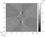
図22は、本変形例に係る心磁計測装置10により得られる1次の勾配磁場分布の一例を示す。図23は、本変形例に係る心磁計測装置10により得られる2次の勾配磁場分布の一例を示す。これらの図は、(X,Y)=(0,−5cm)の点にX=5mm、Y=0.5mm、Z=0.5mmの磁石をN極がX軸の正方向を向くように配置し、(X,Y)=(0,5cm)の点にX=5mm、Y=0.5mm、Z=0.5mmの磁石をN極がX軸の負方向を向くように配置し、30cm×30cmの平面を1cm間隔の格子点で、磁石の置かれた面から高さZ=1cmで心磁計測装置10によって計測した場合の勾配磁場分布を示す。これらの図において、各座標におけるドット密度は任意単位における勾配磁場の大きさを示しており、ドット密度が小さい方が勾配磁場が大きいことを表している。図22は、この条件によって得られた1次の勾配磁場分布のうちの∂B/∂x成分を示した図であり、図23は、この条件によって得られた2次の勾配磁場分布のうちの∂/∂x成分を示した図である。FIG. 22 shows an example of a first-order gradient magnetic field distribution obtained by themagnetocardiographic measuring device 10 according to this modified example. FIG. 23 shows an example of a second-order gradient magnetic field distribution obtained by themagnetocardiographic measuring device 10 according to this modified example. In these figures, magnets with X = 5 mm, Y = 0.5 mm, and Z = 0.5 mm are placed at the point (X, Y) = (0, -5 cm) so that the north pole faces the positive direction of the X axis. Place the magnets with X = 5 mm, Y = 0.5 mm, and Z = 0.5 mm at the point (X, Y) = (0.5 cm) so that the north pole faces the negative direction of the X axis. The gradient magnetic field distribution when a plane of 30 cm × 30 cm is measured by a magneticfield measuring device 10 at a height Z = 1 cm from a surface on which a magnet is placed at lattice points at 1 cm intervals is shown. In these figures, the dot density at each coordinate indicates the magnitude of the gradient magnetic field in an arbitrary unit, and the smaller the dot density, the larger the gradient magnetic field.FIG. 22 is a diagram showing the ∂B x / ∂x component of the first-order gradient magnetic field distribution obtained under this condition, and FIG. 23 is a diagram showing the second-order gradient magnetic field distribution obtained under this condition. it is a diagram showing a ∂2 Bx / ∂x2 components out.

図22および図23に示すように、本変形例に係る心磁計測装置10によれば、算出した勾配磁場を可視化した勾配磁場分布を得ることができる。なお、本図においては、1次の勾配磁場分布については∂B/∂x成分、2次の勾配磁場分布については∂/∂x成分のみを一例として示したが、心磁計測装置10は、他の勾配成分や3次以上の勾配磁場についても同様に勾配磁場分布を得ることができる。As shown in FIGS. 22 and 23, according to themagnetocardiographic measuring device 10 according to the present modification, it is possible to obtain a gradient magnetic field distribution that visualizes the calculated gradient magnetic field. In the present view, .differential.B x/ ∂x component for first-order gradient magnetic field distribution, the secondary gradient magnetic field distribution is described as an example only ∂2 B x/ ∂x2 component, magnetocardiogram The measuringdevice 10 can similarly obtain a gradient magnetic field distribution for other gradient components and gradient magnetic fields of the third order or higher.

図24は、本変形例に係る心磁計測装置10が、指標εを算出して指標εに基づいた制御を行うフローを示す。図24においては、図21と同じステップに対して同じ符号を付すとともに、以下相違点を除き説明を省略する。本図においては、ステップ1920およびステップ1930に代えて、ステップ2400を有する。 FIG. 24 shows a flow in which themagnetocardiographic measuring device 10 according to the present modification calculates the index ε and performs control based on the index ε. In FIG. 24, the same reference numerals are given to the same steps as in FIG. 21, and the description thereof will be omitted except for the following differences. In this figure, step 2400 is provided instead ofstep 1920 and step 1930.

ステップ2400において、指標算出部1770は、計測データから生成した複数の磁気センサセル220における磁場計測データの統計、例えば、較正演算部1730が計測データを較正して生成した複数の磁気センサセル220における磁場計測データの統計に基づいて、指標εを算出する。例えば、指標算出部1770は、次式により、複数の磁気センサセル220における磁場計測データの平均値を計算する。すなわち、指標算出部1770は、複数の磁気センサセル220におけるそれぞれの磁場計測データの総和を、磁気センサセル220の個数で除算することで、磁場計測データの平均値を計算する。

Figure 0006936405
In step 2400, theindex calculation unit 1770 measures the statistics of the magnetic field measurement data in the plurality ofmagnetic sensor cells 220 generated from the measurement data, for example, the magnetic field measurement in the plurality ofmagnetic sensor cells 220 generated by thecalibration calculation unit 1730 calibrating the measurement data. The index ε is calculated based on the statistics of the data. For example, theindex calculation unit 1770 calculates the average value of the magnetic field measurement data in the plurality ofmagnetic sensor cells 220 by the following formula. That is, theindex calculation unit 1770 calculates the average value of the magnetic field measurement data by dividing the sum of the magnetic field measurement data in each of the plurality ofmagnetic sensor cells 220 by the number of themagnetic sensor cells 220.
Figure 0006936405

そして、指標算出部1770は、次式により、複数の磁気センサセル220のそれぞれにおける指標εを算出する。すなわち、指標算出部1770は、磁気センサセル220のそれぞれにおける磁場計測データから、(数26)により計算した磁場計測データの平均値を減算することで、複数の磁気センサセル220のそれぞれにおける指標εを算出する。

Figure 0006936405
Then, theindex calculation unit 1770 calculates the index ε in each of the plurality ofmagnetic sensor cells 220 by the following equation. That is, theindex calculation unit 1770 calculates the index ε in each of the plurality ofmagnetic sensor cells 220 by subtracting the average value of the magnetic field measurement data calculated by (Equation 26) from the magnetic field measurement data in each of themagnetic sensor cells 220. do.
Figure 0006936405

なお、上述の説明では、磁場計測データの平均値からの差に基づいて指標εを算出する場合について説明したが、これに限定されるものではない。指標算出部1770は、例えば、磁気センサセル220のそれぞれにおける磁場計測データから、平均値に代えて、中央値を減算することで、複数の磁気センサセル220のそれぞれにおける指標εを算出してもよい。一般に、平均値は外れ値の影響を受けやすい。したがって、指標算出部1770は、平均値に代えて中央値を用いることで、外れ値の影響を低減した指標εを算出してもよい。このように、指標算出部1770は、複数の磁気センサセル220における磁場計測データの、様々な統計に基づいて、指標εを算出してよい。 In the above description, the case where the index ε is calculated based on the difference from the average value of the magnetic field measurement data has been described, but the present invention is not limited to this. Theindex calculation unit 1770 may calculate the index ε in each of the plurality ofmagnetic sensor cells 220 by subtracting the median value instead of the average value from the magnetic field measurement data in each of themagnetic sensor cells 220, for example. In general, mean values are susceptible to outliers. Therefore, theindex calculation unit 1770 may calculate the index ε with the influence of the outliers reduced by using the median value instead of the average value. In this way, theindex calculation unit 1770 may calculate the index ε based on various statistics of the magnetic field measurement data in the plurality ofmagnetic sensor cells 220.

このように、本変形例に係る心磁計測装置10は、磁場計測データに基づいて指標εを算出するので、図18に示すフローのような複雑な演算を要する信号分離処理を行わずに、指標εを算出することができる。 In this way, themagnetocardiographic measuring device 10 according to the present modification calculates the index ε based on the magnetic field measurement data, so that the signal separation process that requires a complicated calculation such as the flow shown in FIG. 18 is not performed. The index ε can be calculated.

図25は、本実施形態の変形例に係る心磁計測装置10が曲面状に配置された磁気センサアレイ210を用いて心磁を計測する例を示す。本変形例において、磁気センサアレイ210は、X方向、Y方向およびZ方向のそれぞれに複数の磁気センサセル220(例えば、X方向に12個、Y方向に8個、およびZ方向に2個の計192個の磁気センサセル220)が曲面状に配置されている。各磁気センサセル220は、三次元格子空間における曲面形状に含まれる格子点にそれぞれ配置されている。なお、ここで、格子点とは、X方向、Y方向およびZ方向にそれぞれ予め定められた間隔で等間隔に設けられた格子状の点である。一例として、各磁気センサセル220は、X方向、Y方向およびZ方向のいずれか一の方向から見たときに、一の方向に直交する方向に凸を有する曲面に沿うように配置されている。本図においては、各磁気センサセル220が、Y方向から見たときに、Z軸のプラス方向に凸を有する曲面に沿うように配置されている例を示す。磁気センサアレイ210は、曲面状の被験者の胸部周りに沿って巻かれる。すなわち、磁気センサアレイ210は、被験者の胸部周りの曲率と略同等の曲率を有する曲面状に配置される。したがって、磁気センサアレイ210は、被験者の正面中央部がZ軸のプラス方向に突出するような曲面となり、ここでは、このような曲面を凸を有する曲面と表現している。この際、磁気センサアレイ210は、例えば、各磁気センサセル220の各頂点が、Z軸のプラス方向に凸を有する予め定められた曲面を超えない範囲で、できる限りZ軸のマイナス方向に配置されるように、各磁気センサセル220を三次元格子空間における格子点にそれぞれ配置することで、Z軸のプラス方向に凸を有する曲面形状を形成してよい。 FIG. 25 shows an example in which themagnetocardiographic measuring device 10 according to the modified example of the present embodiment measures the magnetocardiography using themagnetic sensor array 210 arranged in a curved surface. In this modification, themagnetic sensor array 210 is a total of a plurality of magnetic sensor cells 220 (for example, 12 in the X direction, 8 in the Y direction, and 2 in the Z direction) in each of the X direction, the Y direction, and the Z direction. 192 magnetic sensor cells 220) are arranged in a curved shape. Eachmagnetic sensor cell 220 is arranged at a lattice point included in a curved surface shape in a three-dimensional lattice space. Here, the grid points are grid-like points provided at equal intervals in the X direction, the Y direction, and the Z direction at predetermined intervals. As an example, eachmagnetic sensor cell 220 is arranged along a curved surface having a protrusion in a direction orthogonal to one direction when viewed from any one of the X direction, the Y direction, and the Z direction. In this figure, an example is shown in which eachmagnetic sensor cell 220 is arranged along a curved surface having a protrusion in the positive direction of the Z axis when viewed from the Y direction. Themagnetic sensor array 210 is wound around the curved subject's chest. That is, themagnetic sensor array 210 is arranged in a curved surface having a curvature substantially equal to the curvature around the chest of the subject. Therefore, themagnetic sensor array 210 has a curved surface such that the central portion of the front surface of the subject protrudes in the positive direction of the Z axis, and such a curved surface is expressed here as a curved surface having a convex shape. At this time, for example, themagnetic sensor array 210 is arranged in the negative direction of the Z axis as much as possible within a range in which each vertex of eachmagnetic sensor cell 220 does not exceed a predetermined curved surface having a convex in the positive direction of the Z axis. As described above, by arranging eachmagnetic sensor cell 220 at each lattice point in the three-dimensional lattice space, a curved surface shape having a convex shape in the positive direction of the Z axis may be formed.

そして、本変形例において、心磁計測装置10は、被験者の胸部が曲面の中心側に位置するように、すなわち、測定対象磁場源である心臓が曲面の中心側に位置するように磁気センサアレイ210を配置して心磁を計測する。これにより、心磁計測装置10は、測定対象磁場源である心臓に近い位置で計測した磁場計測データBを用いて信号空間分離することで、高精度に測定対象磁場と外乱磁場とを分離することができる。同様の理由により、心磁計測装置10は、高精度に磁場の勾配分布を取得することができる。なお、この際、磁気センサアレイ210は、曲面の曲率が被験者の胸部周りの曲率と略同等であると、測定対象磁場源である心臓により近い位置で磁場を計測できるため、好ましい。 Then, in the present modification, themagnetocardiographic measuring device 10 is a magnetic sensor array so that the chest of the subject is located on the center side of the curved surface, that is, the heart, which is the magnetic field source to be measured, is located on the center side of the curved surface.Place 210 and measure the magnetocardiography. As a result, the magneticfield measuring device 10 separates the measurement target magnetic field and the disturbance magnetic field with high accuracy by separating the signal space using the magnetic field measurement data B measured at a position close to the heart, which is the measurement target magnetic field source. be able to. For the same reason, themagnetocardiographic measuring device 10 can acquire the gradient distribution of the magnetic field with high accuracy. At this time, it is preferable that the curvature of the curved surface of themagnetic sensor array 210 is substantially equal to the curvature around the chest of the subject because the magnetic field can be measured at a position closer to the heart, which is the magnetic field source to be measured.

図26は、本実施形態の変形例に係る心磁計測装置10が閉曲面状に配置された磁気センサアレイ210を用いて心磁を計測する例を示す。本変形例において、磁気センサアレイ210は、X方向、Y方向およびZ方向のそれぞれに複数の磁気センサセル220(例えば、X方向に16個、Y方向に8個、およびZ方向に4個の計512個の磁気センサセル220)が閉曲面状に配置されている。各磁気センサセル220は、三次元格子空間における閉曲面形状に含まれる格子点にそれぞれ配置されている。本変形例においても、磁気センサアレイ210は、図25と同様、X方向、Y方向およびZ方向のいずれか一の方向から見たときに、一の方向に直交する方向に凸を有する曲面に沿うように配置された複数の磁気センサセル220を有する。本変形例において、磁気センサアレイ210は、さらに、当該一の方向に直交する方向に凹を有する曲面に沿うように配置された複数の磁気センサセル220を有する。そして、磁気センサアレイ210は、凸を有する曲面形状と凹を有する曲面形状とを合わせて閉曲面形状を形成する。一例として、本図においては、磁気センサアレイ210が、Y方向から見たときに、Z軸のプラス方向に凸を有する曲面に沿うように配置された複数の磁気センサセル220と、Z軸のプラス方向に凹を有する曲面に沿うように配置された複数の磁気センサセル220とを有し、Z軸のプラス方向に凸を有する曲面形状と凹を有する曲面形状とを合わせて閉曲面形状を形成する例を示す。 FIG. 26 shows an example in which themagnetocardiographic measuring device 10 according to the modified example of the present embodiment measures the magnetocardiography using themagnetic sensor array 210 arranged in a closed curved surface. In this modification, themagnetic sensor array 210 has a total of a plurality of magnetic sensor cells 220 (for example, 16 in the X direction, 8 in the Y direction, and 4 in the Z direction) in each of the X direction, the Y direction, and the Z direction. 512 magnetic sensor cells 220) are arranged in a closed curved surface. Eachmagnetic sensor cell 220 is arranged at a lattice point included in a closed curved surface shape in a three-dimensional lattice space. Also in this modification, themagnetic sensor array 210 has a curved surface having a convex shape in a direction orthogonal to one direction when viewed from any one of the X direction, the Y direction, and the Z direction, as in FIG. It has a plurality ofmagnetic sensor cells 220 arranged along the line. In this modification, themagnetic sensor array 210 further has a plurality ofmagnetic sensor cells 220 arranged along a curved surface having a recess in a direction orthogonal to the one direction. Then, themagnetic sensor array 210 forms a closed curved surface shape by combining the curved surface shape having a convex shape and the curved surface shape having a concave shape. As an example, in this figure, themagnetic sensor array 210 has a plurality ofmagnetic sensor cells 220 arranged along a curved surface having a protrusion in the positive direction of the Z axis when viewed from the Y direction, and a positive Z axis. It has a plurality ofmagnetic sensor cells 220 arranged along a curved surface having a concave shape in the direction, and forms a closed curved surface shape by combining a curved surface shape having a convex shape in the positive direction of the Z axis and a curved surface shape having a concave shape. An example is shown.

そして、本変形例において、心磁計測装置10は、被験者の胸部を閉曲面で囲むように、すなわち、測定対象磁場源である心臓を閉曲面で囲むように磁気センサアレイ210を配置して磁場を計測する。これにより、心磁計測装置10は、心臓の電気活動により被験者の前方に生成される心磁に加えて、被験者の後方に生成される心磁を計測し、前方および後方で計測した磁場計測データBを用いて信号空間分離することで、より高精度に測定対象磁場と外乱磁場とを分離することができる。同様の理由により、心磁計測装置10は、高精度に磁場の勾配分布を取得することができる。なお、本変形例においても、図25と同様、磁気センサアレイ210は、曲面の曲率が被験者の胸部周りの曲率と略同等であると、磁場源である心臓により近い位置で磁場を計測できるため、好ましい。 Then, in this modification, themagnetocardiographic measuring device 10 arranges themagnetic sensor array 210 so as to surround the chest of the subject with a closed curved surface, that is, surround the heart, which is the magnetic field source to be measured, with the closed curved surface. To measure. As a result, themagnetocardiographic measuring device 10 measures the magnetocardiography generated behind the subject in addition to the magnetocardiography generated in front of the subject by the electrical activity of the heart, and the magnetic field measurement data measured in the anterior and posterior directions. By separating the signal space using B, the magnetic field to be measured and the disturbance magnetic field can be separated with higher accuracy. For the same reason, themagnetocardiographic measuring device 10 can acquire the gradient distribution of the magnetic field with high accuracy. In this modified example as well, as in FIG. 25, themagnetic sensor array 210 can measure the magnetic field at a position closer to the heart, which is the magnetic field source, when the curvature of the curved surface is substantially the same as the curvature around the chest of the subject. ,preferable.

また、これまでに述べた心磁計測装置10は、ある時刻にそれぞれの磁気センサセル220において出力されるセンサ出力ベクトルΦを用いて信号源を推定することができる。一般に、生体という体積導体内に能動電流が発生すると、これから流出し、またこれに戻る体積電流が導体内に広く分布する。心臓の任意の位置r1における全電流密度をJ(r1)、透磁率をμとすると、計測位置rにおける磁束密度B(r)は、ビオ・サバールの法則を用いて次式のように表すことができる。

Figure 0006936405
Further, themagnetocardiographic measuring device 10 described so far can estimate the signal source by using the sensor output vector Φ output in eachmagnetic sensor cell 220 at a certain time. In general, when an active current is generated in a volume conductor called a living body, the volume current that flows out from the active current and returns to the volume current is widely distributed in the conductor. Assuming that the total current density at an arbitrary position r1 of the heart is J (r1) and the magnetic permeability is μ, the magnetic flux density B (r) at the measurement position r is expressed by the following equation using Biot-Savart's law. Can be done.
Figure 0006936405

ここで、(数28)に基づけば、センサ出力ベクトルΦは、次式に示すように、係数行列Lと電流密度ベクトルJとの内積として表すことができる。

Figure 0006936405
Here, based on (Equation 28), the sensor output vector Φ can be expressed as the inner product of the coefficient matrix L and the current density vector J, as shown in the following equation.
Figure 0006936405

心磁計測装置10は、センサ出力ベクトルΦの値、および、その値が計測された位置を取得することができるので、次式に示すように、当該センサ出力ベクトルΦと係数行列Lの逆行列との内積により、電流密度ベクトルJを算出することができる。これにより、本実施形態に係る心磁計測装置10によれば、センサ出力ベクトルΦに基づいて電流密度ベクトルJを算出するので、計測された磁場からその磁場を発生させた信号源、すなわち、心臓の電気活動によって生成された電流を推定することができる。

Figure 0006936405
Since the magneticfield measuring device 10 can acquire the value of the sensor output vector Φ and the position where the value is measured, it is an inverse matrix of the sensor output vector Φ and the coefficient matrix L as shown in the following equation. The current density vector J can be calculated from the inner product of and. As a result, according to the magneticfield measuring device 10 according to the present embodiment, the current density vector J is calculated based on the sensor output vector Φ, so that the signal source that generated the magnetic field from the measured magnetic field, that is, the heart It is possible to estimate the current generated by the electrical activity of.
Figure 0006936405

図27は、本実施形態に係る磁気センサアレイ210の変形例を示す。図27においては、図16と同じ機能および構成を有する部材に対して同じ符号を付すとともに、以下相違点を除き説明を省略する。本図において、磁気センサアレイ210が有する複数の磁気センサセル220のそれぞれは、角部に空隙(ギャップ)を設けることなく、センサ部300x、300y、および300zが設けられている。このように、複数の磁気センサセル220のそれぞれは、センサ部300をこのように配置しても、各センサ部300x、300y、および300zが、X軸、Y軸、およびZ軸の三次元方向それぞれから見て互いに重ならないように配置することができる。このような配置とすることにより、複数のセンサ部300x、300y、および300zを磁気センサセル220内に分散して配置することができ、1つの角部に複数のセンサ部300x、300y、および300zが集中して配置されることを防ぐことができる。本実施形態に係る心磁計測装置10は、このようにセンサ部300が配置された磁気センサアレイ210を用いて計測データを取得してもよい。 FIG. 27 shows a modified example of themagnetic sensor array 210 according to the present embodiment. In FIG. 27, members having the same functions and configurations as those in FIG. 16 are designated by the same reference numerals, and the description thereof will be omitted except for the following differences. In this figure, each of the plurality ofmagnetic sensor cells 220 included in themagnetic sensor array 210 is provided withsensor portions 300x, 300y, and 300z without providing gaps at the corners. As described above, in each of the plurality ofmagnetic sensor cells 220, even if thesensor unit 300 is arranged in this way, thesensor units 300x, 300y, and 300z are in the three-dimensional directions of the X-axis, the Y-axis, and the Z-axis, respectively. It can be arranged so that they do not overlap each other when viewed from the viewpoint. With such an arrangement, the plurality ofsensor units 300x, 300y, and 300z can be distributed and arranged in themagnetic sensor cell 220, and the plurality ofsensor units 300x, 300y, and 300z can be arranged at one corner. It is possible to prevent them from being arranged in a concentrated manner. Themagnetocardiographic measuring device 10 according to the present embodiment may acquire measurement data using themagnetic sensor array 210 in which thesensor unit 300 is arranged in this way.

本発明の様々な実施形態は、フローチャートおよびブロック図を参照して記載されてよく、ここにおいてブロックは、(1)操作が実行されるプロセスの段階または(2)操作を実行する役割を持つ装置のセクションを表わしてよい。特定の段階およびセクションが、専用回路、コンピュータ可読媒体上に格納されるコンピュータ可読命令と共に供給されるプログラマブル回路、および/またはコンピュータ可読媒体上に格納されるコンピュータ可読命令と共に供給されるプロセッサによって実装されてよい。専用回路は、デジタルおよび/またはアナログハードウェア回路を含んでよく、集積回路(IC)および/またはディスクリート回路を含んでよい。プログラマブル回路は、論理AND、論理OR、論理XOR、論理NAND、論理NOR、および他の論理操作、フリップフロップ、レジスタ、フィールドプログラマブルゲートアレイ(FPGA)、プログラマブルロジックアレイ(PLA)等のようなメモリ要素等を含む、再構成可能なハードウェア回路を含んでよい。 Various embodiments of the present invention may be described with reference to flowcharts and block diagrams, wherein the block is (1) a stage of the process in which the operation is performed or (2) a device responsible for performing the operation. May represent a section of. Specific stages and sections are implemented by dedicated circuits, programmable circuits supplied with computer-readable instructions stored on computer-readable media, and / or processors supplied with computer-readable instructions stored on computer-readable media. You can. Dedicated circuits may include digital and / or analog hardware circuits, and may include integrated circuits (ICs) and / or discrete circuits. Programmable circuits are memory elements such as logical AND, logical OR, logical XOR, logical NAND, logical NOR, and other logical operations, flip-flops, registers, field programmable gate arrays (FPGA), programmable logic arrays (PLA), etc. May include reconfigurable hardware circuits, including, etc.

コンピュータ可読媒体は、適切なデバイスによって実行される命令を格納可能な任意の有形なデバイスを含んでよく、その結果、そこに格納される命令を有するコンピュータ可読媒体は、フローチャートまたはブロック図で指定された操作を実行するための手段を作成すべく実行され得る命令を含む、製品を備えることになる。コンピュータ可読媒体の例としては、電子記憶媒体、磁気記憶媒体、光記憶媒体、電磁記憶媒体、半導体記憶媒体等が含まれてよい。コンピュータ可読媒体のより具体的な例としては、フロッピー(登録商標)ディスク、ディスケット、ハードディスク、ランダムアクセスメモリ(RAM)、リードオンリメモリ(ROM)、消去可能プログラマブルリードオンリメモリ(EPROMまたはフラッシュメモリ)、電気的消去可能プログラマブルリードオンリメモリ(EEPROM)、静的ランダムアクセスメモリ(SRAM)、コンパクトディスクリードオンリメモリ(CD-ROM)、デジタル多用途ディスク(DVD)、ブルーレイ(RTM)ディスク、メモリスティック、集積回路カード等が含まれてよい。 The computer-readable medium may include any tangible device capable of storing instructions executed by the appropriate device, so that the computer-readable medium having the instructions stored therein is specified in a flowchart or block diagram. It will be equipped with a product that contains instructions that can be executed to create a means for performing the operation. Examples of computer-readable media may include electronic storage media, magnetic storage media, optical storage media, electromagnetic storage media, semiconductor storage media, and the like. More specific examples of computer-readable media include floppy® disks, diskettes, hard disks, random access memory (RAM), read-only memory (ROM), erasable programmable read-only memory (EPROM or flash memory), Electrically erasable programmable read-only memory (EEPROM), static random access memory (SRAM), compact disc read-only memory (CD-ROM), digital versatile disc (DVD), Blu-ray (RTM) disc, memory stick, integrated A circuit card or the like may be included.

コンピュータ可読命令は、アセンブラ命令、命令セットアーキテクチャ(ISA)命令、マシン命令、マシン依存命令、マイクロコード、ファームウェア命令、状態設定データ、またはSmalltalk、JAVA(登録商標)、C++等のようなオブジェクト指向プログラミング言語、および「C」プログラミング言語または同様のプログラミング言語のような従来の手続型プログラミング言語を含む、1または複数のプログラミング言語の任意の組み合わせで記述されたソースコードまたはオブジェクトコードのいずれかを含んでよい。 Computer-readable instructions are assembler instructions, instruction set architecture (ISA) instructions, machine instructions, machine-dependent instructions, microcode, firmware instructions, state-setting data, or object-oriented programming such as Smalltalk, JAVA®, C ++, etc. Contains either source code or object code written in any combination of one or more programming languages, including languages and traditional procedural programming languages such as the "C" programming language or similar programming languages. good.

コンピュータ可読命令は、汎用コンピュータ、特殊目的のコンピュータ、若しくは他のプログラム可能なデータ処理装置のプロセッサまたはプログラマブル回路に対し、ローカルにまたはローカルエリアネットワーク(LAN)、インターネット等のようなワイドエリアネットワーク(WAN)を介して提供され、フローチャートまたはブロック図で指定された操作を実行するための手段を作成すべく、コンピュータ可読命令を実行してよい。プロセッサの例としては、コンピュータプロセッサ、処理ユニット、マイクロプロセッサ、デジタル信号プロセッサ、コントローラ、マイクロコントローラ等を含む。 Computer-readable instructions are applied locally to a general purpose computer, a special purpose computer, or the processor or programmable circuit of another programmable data processor, or a wide area network (WAN) such as a local area network (LAN), the Internet, etc. ) May be executed to create a means for performing the operation specified in the flowchart or block diagram. Examples of processors include computer processors, processing units, microprocessors, digital signal processors, controllers, microcontrollers and the like.

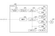
図28は、本発明の複数の態様が全体的または部分的に具現化されてよいコンピュータ2200の例を示す。コンピュータ2200にインストールされたプログラムは、コンピュータ2200に、本発明の実施形態に係る装置に関連付けられる操作または当該装置の1または複数のセクションとして機能させることができ、または当該操作または当該1または複数のセクションを実行させることができ、および/またはコンピュータ2200に、本発明の実施形態に係るプロセスまたは当該プロセスの段階を実行させることができる。そのようなプログラムは、コンピュータ2200に、本明細書に記載のフローチャートおよびブロック図のブロックのうちのいくつかまたはすべてに関連付けられた特定の操作を実行させるべく、CPU2212によって実行されてよい。 FIG. 28 shows an example of acomputer 2200 in which a plurality of aspects of the present invention may be embodied in whole or in part. The program installed on thecomputer 2200 can cause thecomputer 2200 to function as an operation associated with the device according to an embodiment of the present invention or as one or more sections of the device, or the operation or the one or more. Sections can be run and / or thecomputer 2200 can be run a process according to an embodiment of the invention or a stage of such process. Such a program may be run by theCPU 2212 to cause thecomputer 2200 to perform certain operations associated with some or all of the blocks in the flowcharts and block diagrams described herein.

本実施形態によるコンピュータ2200は、CPU2212、RAM2214、グラフィックコントローラ2216、およびディスプレイデバイス2218を含み、それらはホストコントローラ2210によって相互に接続されている。コンピュータ2200はまた、通信インターフェイス2222、ハードディスクドライブ2224、DVD−ROMドライブ2226、およびICカードドライブのような入/出力ユニットを含み、それらは入/出力コントローラ2220を介してホストコントローラ2210に接続されている。コンピュータはまた、ROM2230およびキーボード2242のようなレガシの入/出力ユニットを含み、それらは入/出力チップ2240を介して入/出力コントローラ2220に接続されている。 Thecomputer 2200 according to this embodiment includes aCPU 2212, aRAM 2214, agraphic controller 2216, and adisplay device 2218, which are interconnected by ahost controller 2210. Thecomputer 2200 also includes input / output units such as acommunication interface 2222, ahard disk drive 2224, a DVD-ROM drive 2226, and an IC card drive, which are connected to thehost controller 2210 via the input /output controller 2220. There is. The computer also includes legacy input / output units such as theROM 2230 andkeyboard 2242, which are connected to the input /output controller 2220 via an input /output chip 2240.

CPU2212は、ROM2230およびRAM2214内に格納されたプログラムに従い動作し、それにより各ユニットを制御する。グラフィックコントローラ2216は、RAM2214内に提供されるフレームバッファ等またはそれ自体の中にCPU2212によって生成されたイメージデータを取得し、イメージデータがディスプレイデバイス2218上に表示されるようにする。 TheCPU 2212 operates according to the programs stored in theROM 2230 and theRAM 2214, thereby controlling each unit. Thegraphic controller 2216 acquires the image data generated by theCPU 2212 in a frame buffer or the like provided in theRAM 2214 or itself so that the image data is displayed on thedisplay device 2218.

通信インターフェイス2222は、ネットワークを介して他の電子デバイスと通信する。ハードディスクドライブ2224は、コンピュータ2200内のCPU2212によって使用されるプログラムおよびデータを格納する。DVD−ROMドライブ2226は、プログラムまたはデータをDVD−ROM2201から読み取り、ハードディスクドライブ2224にRAM2214を介してプログラムまたはデータを提供する。ICカードドライブは、プログラムおよびデータをICカードから読み取り、および/またはプログラムおよびデータをICカードに書き込む。 Thecommunication interface 2222 communicates with other electronic devices via the network. Thehard disk drive 2224 stores programs and data used by theCPU 2212 in thecomputer 2200. The DVD-ROM drive 2226 reads the program or data from the DVD-ROM 2201 and provides the program or data to thehard disk drive 2224 via theRAM 2214. The IC card drive reads programs and data from the IC card and / or writes programs and data to the IC card.

ROM2230はその中に、アクティブ化時にコンピュータ2200によって実行されるブートプログラム等、および/またはコンピュータ2200のハードウェアに依存するプログラムを格納する。入/出力チップ2240はまた、様々な入/出力ユニットをパラレルポート、シリアルポート、キーボードポート、マウスポート等を介して、入/出力コントローラ2220に接続してよい。 TheROM 2230 contains a boot program or the like executed by thecomputer 2200 at the time of activation, and / or a program depending on the hardware of thecomputer 2200. The input /output chip 2240 may also connect various input / output units to the input /output controller 2220 via a parallel port, serial port, keyboard port, mouse port, and the like.

プログラムが、DVD−ROM2201またはICカードのようなコンピュータ可読媒体によって提供される。プログラムは、コンピュータ可読媒体から読み取られ、コンピュータ可読媒体の例でもあるハードディスクドライブ2224、RAM2214、またはROM2230にインストールされ、CPU2212によって実行される。これらのプログラム内に記述される情報処理は、コンピュータ2200に読み取られ、プログラムと、上記様々なタイプのハードウェアリソースとの間の連携をもたらす。装置または方法が、コンピュータ2200の使用に従い情報の操作または処理を実現することによって構成されてよい。 The program is provided by a computer-readable medium such as a DVD-ROM 2201 or an IC card. The program is read from a computer-readable medium, installed on ahard disk drive 2224,RAM 2214, orROM 2230, which is also an example of a computer-readable medium, and executed by theCPU 2212. The information processing described in these programs is read by thecomputer 2200 and provides a link between the program and the various types of hardware resources described above. The device or method may be configured to perform manipulation or processing of information in accordance with the use ofcomputer 2200.

例えば、通信がコンピュータ2200および外部デバイス間で実行される場合、CPU2212は、RAM2214にロードされた通信プログラムを実行し、通信プログラムに記述された処理に基づいて、通信インターフェイス2222に対し、通信処理を命令してよい。通信インターフェイス2222は、CPU2212の制御下、RAM2214、ハードディスクドライブ2224、DVD−ROM2201、またはICカードのような記録媒体内に提供される送信バッファ処理領域に格納された送信データを読み取り、読み取られた送信データをネットワークに送信し、またはネットワークから受信された受信データを記録媒体上に提供される受信バッファ処理領域等に書き込む。 For example, when communication is executed between thecomputer 2200 and an external device, theCPU 2212 executes a communication program loaded in theRAM 2214, and performs communication processing on thecommunication interface 2222 based on the processing described in the communication program. You may order. Under the control of theCPU 2212, thecommunication interface 2222 reads and reads transmission data stored in a transmission buffer processing area provided in a recording medium such as aRAM 2214, ahard disk drive 2224, a DVD-ROM 2201, or an IC card. The data is transmitted to the network, or the received data received from the network is written to the reception buffer processing area or the like provided on the recording medium.

また、CPU2212は、ハードディスクドライブ2224、DVD−ROMドライブ2226(DVD−ROM2201)、ICカード等のような外部記録媒体に格納されたファイルまたはデータベースの全部または必要な部分がRAM2214に読み取られるようにし、RAM2214上のデータに対し様々なタイプの処理を実行してよい。CPU2212は次に、処理されたデータを外部記録媒体にライトバックする。 Further, theCPU 2212 causes theRAM 2214 to read all or necessary parts of a file or database stored in an external recording medium such as ahard disk drive 2224, a DVD-ROM drive 2226 (DVD-ROM2201), or an IC card. Various types of processing may be performed on the data on theRAM 2214. TheCPU 2212 then writes back the processed data to an external recording medium.

様々なタイプのプログラム、データ、テーブル、およびデータベースのような様々なタイプの情報が記録媒体に格納され、情報処理を受けてよい。CPU2212は、RAM2214から読み取られたデータに対し、本開示の随所に記載され、プログラムの命令シーケンスによって指定される様々なタイプの操作、情報処理、条件判断、条件分岐、無条件分岐、情報の検索/置換等を含む、様々なタイプの処理を実行してよく、結果をRAM2214に対しライトバックする。また、CPU2212は、記録媒体内のファイル、データベース等における情報を検索してよい。例えば、各々が第2の属性の属性値に関連付けられた第1の属性の属性値を有する複数のエントリが記録媒体内に格納される場合、CPU2212は、第1の属性の属性値が指定される、条件に一致するエントリを当該複数のエントリの中から検索し、当該エントリ内に格納された第2の属性の属性値を読み取り、それにより予め定められた条件を満たす第1の属性に関連付けられた第2の属性の属性値を取得してよい。 Various types of information, such as various types of programs, data, tables, and databases, may be stored on recording media and processed. TheCPU 2212 describes various types of operations, information processing, conditional judgment, conditional branching, unconditional branching, and information retrieval described in various parts of the present disclosure with respect to the data read from theRAM 2214. Various types of processing may be performed, including / replacement, etc., and the results are written back toRAM 2214. Further, theCPU 2212 may search for information in a file, a database, or the like in the recording medium. For example, when a plurality of entries each having an attribute value of the first attribute associated with the attribute value of the second attribute are stored in the recording medium, theCPU 2212 specifies the attribute value of the first attribute. Search for an entry that matches the condition from the plurality of entries, read the attribute value of the second attribute stored in the entry, and associate it with the first attribute that satisfies the predetermined condition. The attribute value of the second attribute obtained may be acquired.

上で説明したプログラムまたはソフトウェアモジュールは、コンピュータ2200上またはコンピュータ2200近傍のコンピュータ可読媒体に格納されてよい。また、専用通信ネットワークまたはインターネットに接続されたサーバーシステム内に提供されるハードディスクまたはRAMのような記録媒体が、コンピュータ可読媒体として使用可能であり、それによりプログラムを、ネットワークを介してコンピュータ2200に提供する。 The program or software module described above may be stored on or near acomputer 2200 on a computer-readable medium. Also, a recording medium such as a hard disk or RAM provided in a dedicated communication network or a server system connected to the Internet can be used as a computer readable medium, thereby providing the program to thecomputer 2200 over the network. do.

以上、本発明を実施の形態を用いて説明したが、本発明の技術的範囲は上記実施の形態に記載の範囲には限定されない。上記実施の形態に、多様な変更または改良を加えることが可能であることが当業者に明らかである。その様な変更または改良を加えた形態も本発明の技術的範囲に含まれ得ることが、請求の範囲の記載から明らかである。また、本発明を実施の形態として、磁場計測装置が心磁計測装置であるとして説明したが、心磁計測装置に限定されるものでなく、人間の心臓以外の臓器の電気活動により生成される磁場を計測する装置(例えば消化器系の医療診断におけるトモグラフィーで使用される装置)であってよい。 Although the present invention has been described above using the embodiments, the technical scope of the present invention is not limited to the scope described in the above embodiments. It will be apparent to those skilled in the art that various changes or improvements can be made to the above embodiments. It is clear from the claims that the form with such modifications or improvements may also be included in the technical scope of the invention. Further, although the magnetic field measuring device has been described as an embodiment of the present invention as a magnetocardiographic measuring device, the present invention is not limited to the magnetocardiographic measuring device and is generated by the electrical activity of an organ other than the human heart. It may be a device that measures the magnetic field (eg, a device used in magnetocardiography in the medical diagnosis of the digestive system).

請求の範囲、明細書、および図面中において示した装置、システム、プログラム、および方法における動作、手順、ステップ、および段階等の各処理の実行順序は、特段「より前に」、「先立って」等と明示しておらず、また、前の処理の出力を後の処理で用いるのでない限り、任意の順序で実現しうることに留意すべきである。請求の範囲、明細書、および図面中の動作フローに関して、便宜上「まず、」、「次に、」等を用いて説明したとしても、この順で実施することが必須であることを意味するものではない。 The order of execution of operations, procedures, steps, steps, etc. in the devices, systems, programs, and methods shown in the claims, specifications, and drawings is particularly "before" and "prior to". It should be noted that it can be realized in any order unless the output of the previous process is used in the subsequent process. Even if the claims, the specification, and the operation flow in the drawings are explained using "first", "next", etc. for convenience, it means that it is essential to carry out in this order. is not it.

10 心磁計測装置
100 本体部
110 磁気センサユニット
120 ヘッド
125 駆動部
130 ベース部
140 ポール部
150 情報処理部
210 磁気センサアレイ
220 磁気センサセル
230 センサデータ収集部
300 センサ部
520 磁気センサ
530 第1の磁場生成部
532 第1の増幅回路
534 第1のコイル
540 出力部
710 磁気抵抗素子
720、730 磁気収束板
910 電流DA変換器
920 第2の磁場生成部
922 第2の増幅回路
924 第2のコイル
1010 磁化自由層
1020 磁化固定層
1700 センサデータ処理部
1710 AD変換器
1712 クロック発生器
1720 計測データ取得部
1721 計測データ演算部
1730 較正演算部
1740 データ出力部
1750 基底ベクトル記憶部
1760 信号空間分離部
1770 指標算出部
1771 基底ベクトル較正部
1780 指標出力部
1790 故障判定部
2000 勾配磁場演算部
2200 コンピュータ
2201 DVD−ROM
2210 ホストコントローラ
2212 CPU
2214 RAM
2216 グラフィックコントローラ
2218 ディスプレイデバイス
2220 入/出力コントローラ
2222 通信インターフェイス
2224 ハードディスクドライブ
2226 DVD−ROMドライブ
2230 ROM
2240 入/出力チップ
2242 キーボード
10Magnetic measurement device 100Main body 110Magnetic sensor unit 120Head 125Drive unit 130Base unit 140Pole unit 150Information processing unit 210Magnetic sensor array 220Magnetic sensor cell 230 Sensordata collection unit 300Sensor unit 520Magnetic sensor 530 First magneticfield Generation unit 532First amplification circuit 534First coil 540Output unit 710Magnetic resistance element 720, 730Magnetic convergence plate 910Current DA converter 920 Second magneticfield generation unit 922Second amplification circuit 924Second coil 1010 Magnetizedfree layer 1020 Magnetized fixedlayer 1700 Sensordata processing unit 1710AD converter 1712Clock generator 1720 Measurementdata acquisition unit 1721 Measurementdata calculation unit 1730Calibration calculation unit 1740Data output unit 1750 Basevector storage unit 1760 Signalspace separation unit 1770Index Calculation unit 1771 Basevector calibration unit 1780Index output unit 1790Failure determination unit 2000 Gradient magneticfield calculation unit 2200Computer 2201 DVD-ROM
2210Host controller 2212 CPU
2214 RAM
2216Graphic controller 2218Display device 2220 Input /output controller 2222Communication interface 2224Hard disk drive 2226 DVD-ROM drive 2230 ROM
2240 Input /Output Chip 2242 Keyboard

Claims (11)

Translated fromJapanese
複数の磁気センサセルを有し、三次元空間内の複数の箇所において3軸方向の入力磁場を検出可能な磁気センサアレイと、
測定対象磁場を含む前記入力磁場に基づく計測データを取得する計測データ取得部と、
前記計測データ取得部が取得した前記計測データを較正する計測データ演算部と、
を備え、
前記計測データ演算部は、
前記計測データ演算部における較正の精度を示す指標を算出する指標算出部と、
前記指標算出部が算出した前記指標に基づいて、故障を判定する故障判定部と、
を有し、
前記複数の磁気センサセルのそれぞれは、
磁気センサと、
出力信号を出力する出力部と、
を有する
磁場計測装置。
A magnetic sensor array that has multiple magnetic sensor cells and can detect input magnetic fields in three axial directions at multiple locations in a three-dimensional space.
A measurement data acquisition unit that acquires measurement data based on the input magnetic field including the magnetic field to be measured, and a measurement data acquisition unit.
A measurement data calculation unit that calibrates the measurement data acquired by the measurement data acquisition unit, and a measurement data calculation unit.
With
The measurement data calculation unit
An index calculation unit that calculates an index indicating the accuracy of calibration in the measurement data calculation unit, and an index calculation unit.
A failure determination unit that determines a failure based on the index calculated by the index calculation unit, and a failure determination unit.
Have,
Each of the plurality of magnetic sensor cells
With a magnetic sensor
The output section that outputs the output signal and
Magnetic field measuring device.
前記複数の磁気センサセルのそれぞれは、前記出力信号に応じた大きさで、前記磁気センサが検出した入力磁場を低減させるフィードバック磁場を発生させる第1の磁場生成部を更に有し、
前記出力部は、前記第1の磁場生成部が前記フィードバック磁場を発生するために流すフィードバック電流に応じた前記出力信号を出力する、
請求項1に記載の磁場計測装置。
Each of the plurality of magnetic sensor cells further has a first magnetic field generator that generates a feedback magnetic field that reduces the input magnetic field detected by the magnetic sensor, having a size corresponding to the output signal.
The output unit outputs the output signal according to the feedback current that the first magnetic field generation unit flows to generate the feedback magnetic field.
The magnetic field measuring device according to claim 1.
前記磁気センサのそれぞれは、磁気抵抗素子と前記磁気抵抗素子の両端に配置された二つの磁気収束板とを含み、前記磁気抵抗素子は、二つの前記磁気収束板に挟まれた位置に配置される、請求項2に記載の磁場計測装置。 Each of the magnetic sensors includes a reluctance element and two reluctance plates arranged at both ends of the reluctance element, and the reluctance element is arranged at a position sandwiched between the two reluctance plates. The magnetic field measuring device according to claim 2. 前記第1の磁場生成部は、前記磁気抵抗素子および二つの前記磁気収束板を取り囲むように、前記磁気センサが検出対象とする磁場の軸方向に沿って巻かれている第1のコイルを含む、請求項3に記載の磁場計測装置。 The first magnetic field generator includes a first coil wound along the axial direction of the magnetic field to be detected by the magnetic sensor so as to surround the magnetic resistance element and the two magnetic focusing plates. , The magnetic field measuring device according to claim 3. 前記複数の磁気センサセルのそれぞれは、前記磁気センサが検出する入力磁場に含まれる環境磁場を低減させるキャンセル磁場を発生させる第2の磁場生成部を更に含み、
前記第2の磁場生成部は、前記磁気抵抗素子および二つの前記磁気収束板を取り囲むように、前記磁気センサが検出対象とする磁場の軸方向に沿って巻かれている第2のコイルを含む、請求項3または4に記載の磁場計測装置。
Each of the plurality of magnetic sensor cells further includes a second magnetic field generator that generates a canceling magnetic field that reduces the environmental magnetic field contained in the input magnetic field detected by the magnetic sensor.
The second magnetic field generator includes a second coil wound along the axial direction of the magnetic field to be detected by the magnetic sensor so as to surround the magnetic resistance element and the two magnetic focusing plates. , The magnetic field measuring device according to claim 3 or 4.
前記複数の磁気センサセルのそれぞれは、前記磁気センサと、前記第1の磁場生成部と、前記出力部とをそれぞれ含む3つのセンサ部を有し、磁場を前記3軸方向で検出可能である、請求項2から5のいずれか一項に記載の磁場計測装置。 Each of the plurality of magnetic sensor cells has three sensor units including the magnetic sensor, the first magnetic field generation unit, and the output unit, and the magnetic field can be detected in the three axial directions. The magnetic field measuring device according to any one of claims 2 to 5. 前記計測データ演算部は、前記計測データから生成した磁場計測データによって示される前記入力磁場の空間分布を、正規直交関数の空間分布を持つ磁場を前記磁気センサアレイで検出したときに前記磁気センサのそれぞれが出力する信号ベクトルを基底ベクトルとして信号分離する信号空間分離部を更に有し、
前記指標算出部は、前記信号空間分離部が信号分離した結果に基づいて、前記指標を算出する、請求項1または6に記載の磁場計測装置。
When the measurement data calculation unit detects the spatial distribution of the input magnetic field indicated by the magnetic field measurement data generated from the measurement data with the magnetic sensor array, the magnetic field having the spatial distribution of the normal orthogonal function of the magnetic sensor It also has a signal space separator that separates signals using the signal vector output by each as the base vector.
The magnetic field measuring device according to claim 1 or 6, wherein the index calculation unit calculates the index based on the result of signal separation by the signal space separation unit.
前記指標算出部は、前記計測データから生成した前記複数の磁気センサセルにおける磁場計測データの統計に基づいて、前記指標を算出する、請求項1から7のいずれか一項に記載の磁場計測装置。 The magnetic field measurement device according to any one of claims 1 to 7, wherein the index calculation unit calculates the index based on statistics of magnetic field measurement data in the plurality of magnetic sensor cells generated from the measurement data. 前記計測データ演算部は、前記指標算出部が算出した前記指標を出力する指標出力部を更に有する、請求項1から8のいずれか一項に記載の磁場計測装置。 The magnetic field measuring device according to any one of claims 1 to 8, wherein the measurement data calculation unit further includes an index output unit that outputs the index calculated by the index calculation unit. 前記計測データ演算部は、前記指標算出部が算出した前記指標に基づいて、前記計測データを再較正する、請求項1から9のいずれか一項に記載の磁場計測装置。 The magnetic field measuring device according to any one of claims 1 to 9, wherein the measurement data calculation unit recalibrates the measurement data based on the index calculated by the index calculation unit. 前記磁気センサアレイは、曲面状に配置される、請求項1から10のいずれか一項に記載の磁場計測装置。 The magnetic field measuring device according to any one of claims 1 to 10, wherein the magnetic sensor array is arranged in a curved surface.
JP2020563345A2018-12-262019-12-25 Magnetic field measuring deviceActiveJP6936405B2 (en)

Priority Applications (1)

Application NumberPriority DateFiling DateTitle
JP2021138107AJP7487156B2 (en)2018-12-262021-08-26 Magnetic field measurement device

Applications Claiming Priority (3)

Application NumberPriority DateFiling DateTitle
JP20182432532018-12-26
PCT/JP2019/050826WO2020138170A1 (en)2018-12-262019-12-25Magnetic field measuring device

Related Child Applications (1)

Application NumberTitlePriority DateFiling Date
JP2021138107ADivisionJP7487156B2 (en)2018-12-262021-08-26 Magnetic field measurement device

Publications (2)

Publication NumberPublication Date
JPWO2020138170A1 JPWO2020138170A1 (en)2021-09-09
JP6936405B2true JP6936405B2 (en)2021-09-15

Family

ID=71125786

Family Applications (2)

Application NumberTitlePriority DateFiling Date
JP2020563345AActiveJP6936405B2 (en)2018-12-262019-12-25 Magnetic field measuring device
JP2021138107AActiveJP7487156B2 (en)2018-12-262021-08-26 Magnetic field measurement device

Family Applications After (1)

Application NumberTitlePriority DateFiling Date
JP2021138107AActiveJP7487156B2 (en)2018-12-262021-08-26 Magnetic field measurement device

Country Status (3)

CountryLink
US (1)US11927646B2 (en)
JP (2)JP6936405B2 (en)
WO (1)WO2020138170A1 (en)

Families Citing this family (10)

* Cited by examiner, † Cited by third party
Publication numberPriority datePublication dateAssigneeTitle
US20190377035A1 (en)*2018-06-082019-12-12Asahi Kasei Microdevices CorporationMagnetic field measurement apparatus, magnetic field measurement method, and storage medium with magnetic field measurement program stored thereon
WO2020040168A1 (en)2018-08-222020-02-27旭化成エレクトロニクス株式会社Magnetic field measurement device, magnetic field measurement method, and magnetic field measurement program
JP6936405B2 (en)2018-12-262021-09-15旭化成エレクトロニクス株式会社 Magnetic field measuring device
CN113874742B (en)*2019-05-312024-12-06旭化成株式会社 Measuring device, measuring method and computer readable medium
JP7393319B2 (en)2020-12-032023-12-06株式会社東芝 Magnetic sensor and inspection equipment
JP7422709B2 (en)2021-09-072024-01-26株式会社東芝 Sensors and inspection equipment
JP2024034793A (en)2022-09-012024-03-13株式会社東芝Sensor and inspection device
DE102022209426A1 (en)*2022-09-092024-03-14Robert Bosch Gesellschaft mit beschränkter Haftung Device for detecting magnetic signals generated by a beating heart
US12310734B2 (en)2023-03-172025-05-27SB Technology, Inc.Systems and methods for biomagnetic field imaging
US20250056185A1 (en)*2023-08-082025-02-13Astra Navigation, Inc.Using a Magnetic Recording for Authentication

Family Cites Families (117)

* Cited by examiner, † Cited by third party
Publication numberPriority datePublication dateAssigneeTitle
JPH06103340B2 (en)1988-02-011994-12-14シャープ株式会社 Magnetic sensor
JPH06103339B2 (en)1989-12-281994-12-14株式会社ミシマタイムインダストリー Magnetic field measuring instrument
JPH05232202A (en)1992-02-251993-09-07Fujitsu Ltd Software Gladiometer
US5642045A (en)1995-08-181997-06-24International Business Machines CorporationMagnetic field gradiometer with improved correction circuits
JPH09127252A (en)1995-10-261997-05-16Kokusai Denshin Denwa Co Ltd <Kdd> Submarine cable exploration system
JPH09243725A (en)1996-03-061997-09-19Kanazawa Kogyo UnivMethod of measuring magnetic distribution, magnetic distribution measuring device, and magnetic detector plate
JP3518493B2 (en)1997-03-072004-04-12株式会社日立製作所 Calculation method of isometric diagram of biomagnetic field
JPH10286244A (en)1997-04-151998-10-27Shimadzu Corp Biological activity current source estimation device
JP3230460B2 (en)1997-06-172001-11-19株式会社島津製作所 Biomagnetic measurement device
US5990679A (en)1997-10-221999-11-23The United States Of America As Represented By The Secretary Of The NavyMethod using corrective factors for determining a magnetic gradient
JP4077945B2 (en)1998-08-112008-04-23株式会社東芝 Biomagnetic measurement device
JP3563624B2 (en)1999-02-022004-09-08株式会社日立製作所 Biomagnetic field measurement device
JP4427122B2 (en)1999-03-302010-03-03株式会社東芝 SQUID magnetometer
JP2001083224A (en)1999-09-162001-03-30Ddi Corp Magnetic field measurement method and apparatus
US6376933B1 (en)1999-12-312002-04-23Honeywell International Inc.Magneto-resistive signal isolator
US6480111B2 (en)2000-01-102002-11-12Southwest Research InstituteMotion detection for physiological applications
JP3406273B2 (en)2000-03-282003-05-12株式会社エムティアイ Disturbance magnetic field cancellation device
JP2002272695A (en)2001-03-142002-09-24Ryuzo UedaVersatile high-sensitivity magnetic detection device
JP3925301B2 (en)2001-07-122007-06-06コニカミノルタセンシング株式会社 Spectral characteristic measuring apparatus and wavelength shift correction method for spectral sensitivity of the same
JP4460808B2 (en)2001-09-072010-05-12親良 炭 Current density vector estimation device and electrical conductivity estimation device
CN1295514C (en)2001-11-012007-01-17旭化成电子材料元件株式会社 Current sensor and method for manufacturing the current sensor
JP3944383B2 (en)2001-11-162007-07-11株式会社日立製作所 Cardiac magnetic field measuring device
JP4286664B2 (en)2001-11-282009-07-01親良 炭 Dielectric constant or conductivity estimation device
EP1535305A2 (en)2002-08-162005-06-01Brown University Research FoundationScanning magnetic microscope having improved magnetic sensor
US7259545B2 (en)2003-02-112007-08-21Allegro Microsystems, Inc.Integrated sensor
JP2004271303A (en)2003-03-072004-09-30Hitachi Metals LtdMagnetic measurement system and position detection device for underground excavator using it
FI115324B (en)*2003-03-142005-04-15Elekta Neuromag Oy Method and systems for processing a multichannel measurement signal
JP3642061B2 (en)2003-05-192005-04-27株式会社日立製作所 Magnetic field measuring device
JP4263544B2 (en)*2003-06-232009-05-13株式会社日立ハイテクノロジーズ Magnetic field measuring device
JP4287905B2 (en)2003-07-312009-07-01光照 木村 Semiconductor magnetic sensor and magnetic measuring device using the same
FI115737B (en)2003-09-262005-06-30Elekta Neuromag Oy A method for using a multichannel measurement signal in source modeling
FR2860879B1 (en)2003-10-082006-02-03Centre Nat Etd Spatiales PROBE FOR MEASURING A MAGNETIC FIELD.
JP4638670B2 (en)2003-12-262011-02-23旭化成エレクトロニクス株式会社 Azimuth angle measuring method and azimuth angle measuring apparatus
FI115736B (en)2004-01-192005-06-30Elekta Neuromag Oy A method for separating multi-channel signals from AC and DC sources
JP2005217341A (en)2004-02-022005-08-11Kri IncEnvironmental magnetism noise shielding equipment
FI118577B (en)2004-02-132007-12-31Elekta Ab Procedure for protecting measuring device against interference
US6841994B1 (en)2004-03-012005-01-11The United States Of America As Represented By The Secretary Of The NavyMagnetic anomaly sensing system for detection, localization and classification of magnetic objects
JP4110108B2 (en)2004-03-262008-07-02株式会社日立ハイテクノロジーズ Biomagnetic field measurement device, horizontal position setting method for biomagnetic field measurement
JP2006047080A (en)2004-08-042006-02-16Advanced Telecommunication Research Institute International Magnetic sensor
JP4521239B2 (en)2004-09-102010-08-11株式会社日立ハイテクノロジーズ Magnetic field shielding device and biomagnetic field measuring device
EP1795864A4 (en)2004-09-292011-11-02Amosense Co LtdMagnetic sensor control method, magnetic sensor controller and portable terminal device
FI119133B (en)2005-04-282008-07-31Elekta Ab Method and apparatus for eliminating interference during electromagnetic multichannel measurement
JP2008032562A (en)2006-07-282008-02-14Ntn CorpRotation detector, and bearing with rotation detector
US7342399B1 (en)2006-04-172008-03-11The United States Of America As Represented By The Secretary Of The NavyMagnetic anomaly sensing-based system for tracking a moving magnetic target
JP4222520B2 (en)2006-04-172009-02-12防衛省技術研究本部長 Gradient magnetometer adjustment method
JP5022660B2 (en)2006-10-062012-09-12株式会社日立ハイテクノロジーズ Magnetic field measuring device
JP2008142154A (en)2006-12-072008-06-26Hitachi High-Technologies Corp Biomagnetic field measurement apparatus and parallel projection method on biological model
JP5361131B2 (en)2007-01-032013-12-04エレクタ アクチボラゲット Analysis of multi-channel measurement data using orthogonal virtual channels
US20100277163A1 (en)2007-02-092010-11-04Asahi Kasei Emd CorporationSpatial Information Detecting System, its Detecting Method, and Spatial Information Detecting Device
US7603251B1 (en)2008-06-232009-10-13The United States Of America As Represented By The Secretary Of The NavyMagnetic anomaly sensing system for detection, localization and classification of a magnetic object in a cluttered field of magnetic anomalies
JP5365367B2 (en)2009-06-242013-12-11セイコーエプソン株式会社 Magnetic sensor
JP5083837B2 (en)2009-08-282012-11-28防衛省技術研究本部長 Magnetic measurement system
US8390283B2 (en)2009-09-252013-03-05Everspin Technologies, Inc.Three axis magnetic field sensor
DE102010005056A1 (en)2010-01-202011-07-21Emitec Gesellschaft für Emissionstechnologie mbH, 53797 Container for a liquid, in particular a reducing agent
JP2011220977A (en)2010-04-142011-11-04Fujikura LtdMagnetic field detector
FI124427B (en)2010-07-062014-08-29Elekta Ab Procedure for precise interference space in biomagnetic field measurements
WO2012032962A1 (en)*2010-09-102012-03-15コニカミノルタオプト株式会社Biomagnetism measuring device, biomagnetism measuring system, and biomagnetism measuring method
JP5712640B2 (en)2011-01-282015-05-07コニカミノルタ株式会社 Magnetic measuring device and biomagnetic measuring method
JP5541179B2 (en)2011-01-282014-07-09コニカミノルタ株式会社 Magnetic sensor and biomagnetic measuring device using the same
DE102011083961B4 (en)2011-10-042023-12-21Robert Bosch Gmbh Method for calibrating a three-axis sensor and sensor
JP2013124873A (en)2011-12-132013-06-24Seiko Epson CorpMagnetic field measuring system and cell array
FI125397B (en)2012-01-242015-09-30Elekta Ab Method for using spatial and temporal oversampling in multichannel measurements
US9201122B2 (en)*2012-02-162015-12-01Allegro Microsystems, LlcCircuits and methods using adjustable feedback for self-calibrating or self-testing a magnetic field sensor with an adjustable time constant
JP2013217690A (en)2012-04-052013-10-24Seiko Epson CorpMagnetic field correction device and magnetic field measuring device
JP5897719B2 (en)2012-08-312016-03-30株式会社日立製作所 Magnetoresistive sensor, gradiometer
JP6089572B2 (en)2012-10-182017-03-08ヤマハ株式会社 Magnetoresistive element reset circuit
US9864019B2 (en)2012-10-242018-01-09Cae Inc.Magnetic sensor system
JP2014134388A (en)2013-01-082014-07-24Shimadzu CorpMagnetic measuring device
JP5924695B2 (en)2013-02-042016-05-25三菱電機株式会社 Magnetic field detection device, current detection device, semiconductor integrated circuit, and magnetic field detection method
JP6021239B2 (en)2013-02-132016-11-09マグネデザイン株式会社 3D magnetic field detection element and 3D magnetic field detection device
US20140257104A1 (en)2013-03-052014-09-11Ezono AgMethod and system for ultrasound imaging
US9488700B2 (en)2013-09-122016-11-08Infineon Technologies AgMagnetic field sensors and systems with sensor circuit portions having different bias voltages and frequency ranges
JP2015075465A (en)2013-10-112015-04-20旭化成エレクトロニクス株式会社Three-dimensional magnetic field measuring apparatus and three-dimensional magnetic field measuring method
JP2015102512A (en)2013-11-272015-06-04愛知製鋼株式会社Magnetic field generation device and offset calculation method
JP2017026312A (en)2013-12-022017-02-02コニカミノルタ株式会社Three-dimensional magnetic sensor
WO2015095180A1 (en)2013-12-182015-06-25Bench Tree Group, LlcSystem and method of directional sensor calibration
US9507005B2 (en)2014-03-052016-11-29Infineon Technologies AgDevice and current sensor for providing information indicating a safe operation of the device of the current sensor
JP2015219061A (en)2014-05-152015-12-07Tdk株式会社Magnetic field detection sensor and magnetic field detection device using the same
JP6210458B2 (en)2014-07-302017-10-11パナソニックIpマネジメント株式会社 Failure detection system and failure detection method
US10466071B2 (en)2014-08-062019-11-05Infineon Technologies AgTrue-phase two-dimensional magnetic field sensor
JP6267613B2 (en)2014-09-252018-01-24アルプス電気株式会社 Magnetic sensor and current sensor including the magnetic sensor
JP6494269B2 (en)2014-12-172019-04-03ルネサスエレクトロニクス株式会社 Magnetic measuring device
JP2016183944A (en)2015-03-272016-10-20旭化成エレクトロニクス株式会社Magnetic field detection method, magnetic sensor, and biomagnetic sensor
JP2016217930A (en)2015-05-222016-12-22セイコーエプソン株式会社 Magnetic measurement system
JP6530245B2 (en)2015-06-052019-06-12旭化成エレクトロニクス株式会社 Detection device, magnetic sensor, detection method, and program
JP2017000354A (en)2015-06-092017-01-05セイコーエプソン株式会社Magnetic field measurement device and magnetic field measurement method
JP6638582B2 (en)2015-09-102020-01-29株式会社リコー Magnetic measuring device
JP2017062122A (en)2015-09-232017-03-30国立大学法人名古屋大学 Magnetic field detector
US20170090003A1 (en)2015-09-302017-03-30Apple Inc.Efficient testing of magnetometer sensor assemblies
JP6766333B2 (en)*2015-10-062020-10-14愛知製鋼株式会社 Micromagnetic material detection sensor and foreign matter detection device
JP6021238B1 (en)2015-10-112016-11-09マグネデザイン株式会社 Gradio sensor element and gradio sensor
JP6581516B2 (en)2016-01-262019-09-25株式会社東芝 Magnetic sensor and magnetic sensor device
JP6595923B2 (en)2016-01-282019-10-23株式会社ゼンリンデータコム Location management system and location management method
JP6666732B2 (en)2016-01-292020-03-18株式会社アドバンテスト Magnetic noise canceling device and magnetic field measuring device
JP2017166921A (en)2016-03-152017-09-21株式会社東芝 Magnetic sensor and magnetic sensor device
JP2017191039A (en)2016-04-142017-10-19セイコーエプソン株式会社Magnetic field measurement device and calibration method for the same
JP2017191040A (en)2016-04-142017-10-19セイコーエプソン株式会社Magnetic field measurement device and magnetic field measurement method
EP3467529B1 (en)2016-05-242021-12-01TDK CorporationMagnetic sensor
JP7075340B2 (en)2016-06-032022-05-25国立大学法人 東京医科歯科大学 Biomagnetic measuring device
JP6822127B2 (en)2016-06-232021-01-27Tdk株式会社 Magnetic sensor
JP2018004286A (en)2016-06-282018-01-11株式会社リコーSignal processing device, signal processing method, signal processing program, and magnetic field measurement system
JP6748499B2 (en)2016-07-132020-09-02株式会社アドバンテスト Magnetic field measuring device and magnetic field measuring method
JP6645926B2 (en)2016-07-222020-02-14日本電信電話株式会社 Biological signal processing method and apparatus
JP2018054461A (en)2016-09-292018-04-05大同特殊鋼株式会社Three axial magnetic sensor, connection module, and sensor probe
US10155154B2 (en)2017-01-102018-12-18Sony Interactive Entertainment Inc.Variable magnetic field-based position
US11047931B2 (en)2017-04-112021-06-29Apple Inc.Magnetic field sensor array with electromagnetic interference cancellation
US10324141B2 (en)*2017-05-262019-06-18Allegro Microsystems, LlcPackages for coil actuated position sensors
FR3069329B1 (en)2017-07-212019-08-23Sysnav METHOD AND DEVICE FOR MEASURING THE MAGNETIC FIELD BY MAGNETOMETERS
US10718825B2 (en)2017-09-132020-07-21Nxp B.V.Stray magnetic field robust magnetic field sensor and system
WO2019131816A1 (en)2017-12-272019-07-04旭化成エレクトロニクス株式会社Magnetic sensor module
US10509082B2 (en)2018-02-082019-12-17Nxp B.V.Magnetoresistive sensor systems with stray field cancellation utilizing auxiliary sensor signals
JP2019215322A (en)*2018-06-082019-12-19旭化成エレクトロニクス株式会社Magnetic field measurement device, magnetic field measurement method, and magnetic field measurement program
WO2020040168A1 (en)2018-08-222020-02-27旭化成エレクトロニクス株式会社Magnetic field measurement device, magnetic field measurement method, and magnetic field measurement program
JP6936405B2 (en)2018-12-262021-09-15旭化成エレクトロニクス株式会社 Magnetic field measuring device
CN113874742B (en)2019-05-312024-12-06旭化成株式会社 Measuring device, measuring method and computer readable medium
JP7328044B2 (en)2019-07-222023-08-16マクセル株式会社 Detection device and detection method
JP7525297B2 (en)2020-05-082024-07-30旭化成エレクトロニクス株式会社 Magnetic field measurement device, magnetic field measurement method, and magnetic field measurement program

Also Published As

Publication numberPublication date
JPWO2020138170A1 (en)2021-09-09
US11927646B2 (en)2024-03-12
US20210286023A1 (en)2021-09-16
JP2021192043A (en)2021-12-16
JP7487156B2 (en)2024-05-20
WO2020138170A1 (en)2020-07-02

Similar Documents

PublicationPublication DateTitle
JP6936405B2 (en) Magnetic field measuring device
JP6761138B2 (en) Magnetic field measuring device, magnetic field measuring method, magnetic field measuring program
JP7186652B2 (en) magnetocardiograph
JP7204908B2 (en) Measuring device, measuring method and program
JP7525297B2 (en) Magnetic field measurement device, magnetic field measurement method, and magnetic field measurement program
US20190377035A1 (en)Magnetic field measurement apparatus, magnetic field measurement method, and storage medium with magnetic field measurement program stored thereon
US11774518B2 (en)Magnetic field measuring apparatus, magnetic field measuring method and recording medium with magnetic field measuring program recorded thereon
JP2019215322A (en)Magnetic field measurement device, magnetic field measurement method, and magnetic field measurement program
US20200281490A1 (en)Magnetic field measurement apparatus
JP7365915B2 (en) measuring device
JP2023147067A (en)Magnetic field measurement device, magnetic field measurement method, and magnetic field measurement program
JP7330014B2 (en) Magnetocardiography device, magnetocardiography method, and magnetocardiography program
JP2020139840A (en) Measuring device, signal processing device, signal processing method, and signal processing program
US11668772B2 (en)Magnetic field measurement device, magnetic field measurement method, and recording medium having recorded thereon magnetic field measurement program
JP7636933B2 (en) MEASURING APPARATUS, MEASURING METHOD, AND PROGRAM
JP7364485B2 (en) Magnetic field measurement device, magnetic field measurement method, and magnetic field measurement program
JP2021113801A (en)Magnetic field measurement device, magnetic field measurement method, and magnetic field measurement program
JP2021120619A (en) Magnetic field measuring device, magnetic field measuring method, and magnetic field measuring program
JP2024140527A (en) CALIBRATION APPARATUS, CALIBRATION METHOD, AND CALIBRATION PROGRAM
JP2023134200A (en)Magnetic field measurement device, method for measuring magnetic field, and magnetic field measurement program
JP2022153083A (en) Measuring device, measuring method and program
JP2022153075A (en) Measuring device, measuring method and program

Legal Events

DateCodeTitleDescription
A621Written request for application examination

Free format text:JAPANESE INTERMEDIATE CODE: A621

Effective date:20201127

TRDDDecision of grant or rejection written
A01Written decision to grant a patent or to grant a registration (utility model)

Free format text:JAPANESE INTERMEDIATE CODE: A01

Effective date:20210727

A61First payment of annual fees (during grant procedure)

Free format text:JAPANESE INTERMEDIATE CODE: A61

Effective date:20210826

R150Certificate of patent or registration of utility model

Ref document number:6936405

Country of ref document:JP

Free format text:JAPANESE INTERMEDIATE CODE: R150


[8]ページ先頭

©2009-2025 Movatter.jp