JP6936148B2 - Surgical instruments - Google Patents
Surgical instrumentsDownload PDFInfo
- Publication number
- JP6936148B2 JP6936148B2JP2017543763AJP2017543763AJP6936148B2JP 6936148 B2JP6936148 B2JP 6936148B2JP 2017543763 AJP2017543763 AJP 2017543763AJP 2017543763 AJP2017543763 AJP 2017543763AJP 6936148 B2JP6936148 B2JP 6936148B2
- Authority
- JP
- Japan
- Prior art keywords
- pulley
- actuation
- jaw
- yaw
- pitch
- Prior art date
- Legal status (The legal status is an assumption and is not a legal conclusion. Google has not performed a legal analysis and makes no representation as to the accuracy of the status listed.)
- Active
Links
Images


Classifications
- A—HUMAN NECESSITIES
- A61—MEDICAL OR VETERINARY SCIENCE; HYGIENE
- A61B—DIAGNOSIS; SURGERY; IDENTIFICATION
- A61B34/00—Computer-aided surgery; Manipulators or robots specially adapted for use in surgery
- A61B34/70—Manipulators specially adapted for use in surgery
- A61B34/71—Manipulators operated by drive cable mechanisms
- A—HUMAN NECESSITIES
- A61—MEDICAL OR VETERINARY SCIENCE; HYGIENE
- A61B—DIAGNOSIS; SURGERY; IDENTIFICATION
- A61B17/00—Surgical instruments, devices or methods
- A61B17/00234—Surgical instruments, devices or methods for minimally invasive surgery
- A—HUMAN NECESSITIES
- A61—MEDICAL OR VETERINARY SCIENCE; HYGIENE
- A61B—DIAGNOSIS; SURGERY; IDENTIFICATION
- A61B17/00—Surgical instruments, devices or methods
- A61B17/28—Surgical forceps
- A61B17/29—Forceps for use in minimally invasive surgery
- A61B17/2909—Handles
- A—HUMAN NECESSITIES
- A61—MEDICAL OR VETERINARY SCIENCE; HYGIENE
- A61B—DIAGNOSIS; SURGERY; IDENTIFICATION
- A61B17/00—Surgical instruments, devices or methods
- A61B17/00234—Surgical instruments, devices or methods for minimally invasive surgery
- A61B2017/00292—Surgical instruments, devices or methods for minimally invasive surgery mounted on or guided by flexible, e.g. catheter-like, means
- A61B2017/003—Steerable
- A61B2017/00318—Steering mechanisms
- A61B2017/00323—Cables or rods
- A—HUMAN NECESSITIES
- A61—MEDICAL OR VETERINARY SCIENCE; HYGIENE
- A61B—DIAGNOSIS; SURGERY; IDENTIFICATION
- A61B17/00—Surgical instruments, devices or methods
- A61B2017/0042—Surgical instruments, devices or methods with special provisions for gripping
- A61B2017/00424—Surgical instruments, devices or methods with special provisions for gripping ergonomic, e.g. fitting in fist
- A—HUMAN NECESSITIES
- A61—MEDICAL OR VETERINARY SCIENCE; HYGIENE
- A61B—DIAGNOSIS; SURGERY; IDENTIFICATION
- A61B17/00—Surgical instruments, devices or methods
- A61B2017/0042—Surgical instruments, devices or methods with special provisions for gripping
- A61B2017/00438—Surgical instruments, devices or methods with special provisions for gripping connectable to a finger
- A—HUMAN NECESSITIES
- A61—MEDICAL OR VETERINARY SCIENCE; HYGIENE
- A61B—DIAGNOSIS; SURGERY; IDENTIFICATION
- A61B17/00—Surgical instruments, devices or methods
- A61B2017/00477—Coupling
- A—HUMAN NECESSITIES
- A61—MEDICAL OR VETERINARY SCIENCE; HYGIENE
- A61B—DIAGNOSIS; SURGERY; IDENTIFICATION
- A61B17/00—Surgical instruments, devices or methods
- A61B2017/00681—Aspects not otherwise provided for
- A61B2017/00738—Aspects not otherwise provided for part of the tool being offset with respect to a main axis, e.g. for better view for the surgeon
- A—HUMAN NECESSITIES
- A61—MEDICAL OR VETERINARY SCIENCE; HYGIENE
- A61B—DIAGNOSIS; SURGERY; IDENTIFICATION
- A61B17/00—Surgical instruments, devices or methods
- A61B17/28—Surgical forceps
- A61B17/29—Forceps for use in minimally invasive surgery
- A61B2017/2901—Details of shaft
- A61B2017/2904—Details of shaft curved, but rigid
- A—HUMAN NECESSITIES
- A61—MEDICAL OR VETERINARY SCIENCE; HYGIENE
- A61B—DIAGNOSIS; SURGERY; IDENTIFICATION
- A61B17/00—Surgical instruments, devices or methods
- A61B17/28—Surgical forceps
- A61B17/29—Forceps for use in minimally invasive surgery
- A61B2017/2901—Details of shaft
- A61B2017/2908—Multiple segments connected by articulations
- A—HUMAN NECESSITIES
- A61—MEDICAL OR VETERINARY SCIENCE; HYGIENE
- A61B—DIAGNOSIS; SURGERY; IDENTIFICATION
- A61B17/00—Surgical instruments, devices or methods
- A61B17/28—Surgical forceps
- A61B17/29—Forceps for use in minimally invasive surgery
- A61B17/2909—Handles
- A61B2017/291—Handles the position of the handle being adjustable with respect to the shaft
- A—HUMAN NECESSITIES
- A61—MEDICAL OR VETERINARY SCIENCE; HYGIENE
- A61B—DIAGNOSIS; SURGERY; IDENTIFICATION
- A61B17/00—Surgical instruments, devices or methods
- A61B17/28—Surgical forceps
- A61B17/29—Forceps for use in minimally invasive surgery
- A61B17/2909—Handles
- A61B2017/2911—Handles rings
- A—HUMAN NECESSITIES
- A61—MEDICAL OR VETERINARY SCIENCE; HYGIENE
- A61B—DIAGNOSIS; SURGERY; IDENTIFICATION
- A61B17/00—Surgical instruments, devices or methods
- A61B17/28—Surgical forceps
- A61B17/29—Forceps for use in minimally invasive surgery
- A61B17/2909—Handles
- A61B2017/2912—Handles transmission of forces to actuating rod or piston
- A61B2017/2923—Toothed members, e.g. rack and pinion
- A—HUMAN NECESSITIES
- A61—MEDICAL OR VETERINARY SCIENCE; HYGIENE
- A61B—DIAGNOSIS; SURGERY; IDENTIFICATION
- A61B17/00—Surgical instruments, devices or methods
- A61B17/28—Surgical forceps
- A61B17/29—Forceps for use in minimally invasive surgery
- A61B2017/2926—Details of heads or jaws
- A61B2017/2932—Transmission of forces to jaw members
- A61B2017/2939—Details of linkages or pivot points
- A61B2017/294—Connection of actuating rod to jaw, e.g. releasable
- A—HUMAN NECESSITIES
- A61—MEDICAL OR VETERINARY SCIENCE; HYGIENE
- A61B—DIAGNOSIS; SURGERY; IDENTIFICATION
- A61B17/00—Surgical instruments, devices or methods
- A61B17/28—Surgical forceps
- A61B17/29—Forceps for use in minimally invasive surgery
- A61B2017/2926—Details of heads or jaws
- A61B2017/2932—Transmission of forces to jaw members
- A61B2017/2944—Translation of jaw members
Landscapes
- Health & Medical Sciences (AREA)
- Surgery (AREA)
- Life Sciences & Earth Sciences (AREA)
- Engineering & Computer Science (AREA)
- Medical Informatics (AREA)
- Biomedical Technology (AREA)
- Heart & Thoracic Surgery (AREA)
- Nuclear Medicine, Radiotherapy & Molecular Imaging (AREA)
- Molecular Biology (AREA)
- Animal Behavior & Ethology (AREA)
- General Health & Medical Sciences (AREA)
- Public Health (AREA)
- Veterinary Medicine (AREA)
- Robotics (AREA)
- Ophthalmology & Optometry (AREA)
- Surgical Instruments (AREA)
Description
Translated fromJapanese本発明は、手術用インスツルメントに係り、詳細には、腹腔鏡手術、または多様な手術に使用するために、手動で作動可能な手術用インスツルメントに関する。 The present invention relates to surgical instruments, and more particularly to surgical instruments that can be manually actuated for use in laparoscopic surgery, or a variety of surgical procedures.
医学的に手術とは、皮膚や粘膜、その他組織を、医療機器を使用して、切ったり裂いたりするような操作を加えて病気を直すことをいう。特に、手術部位の皮膚を切開して開き、その内部にある器官などを治療、成形したり除去したりする開腹手術などは、出血、副作用、患者の苦痛、傷痕などの問題を引き起こす。従って、最近では、皮膚に所定の孔を形成し、医療機器、例えば、腹腔鏡、手術用インスツルメント、微細手術用顕微鏡などだけを挿入して行う手術、またはロボット(robot)を使用した手術が代案として脚光を浴びている。 Medically, surgery refers to repairing a disease by cutting or tearing the skin, mucous membranes, or other tissues using a medical device. In particular, open surgery, in which the skin at the surgical site is incised and opened to treat, shape, or remove the internal organs, causes problems such as bleeding, side effects, patient pain, and scars. Therefore, recently, surgery performed by forming a predetermined hole in the skin and inserting only a medical device such as a laparoscope, a surgical instrument, a microscope for microsurgery, or a surgery using a robot (robot). Is in the limelight as an alternative.
手術用インスツルメントは、皮膚に穿孔された孔を通過するシャフトの一端に具備されたエンドツールを、所定の駆動部を使用して、医師が直接手で操作したり、ロボットアームを使用して操作したりすることにより、手術部位を手術するための道具である。手術用インスツルメントに具備されたエンドツールの所定構造を介した回転動作、つまみ動作(gripping)、切断動作(cutting)などを遂行する。 Surgical instruments are made by manually manipulating an end tool at one end of a shaft that passes through a hole drilled in the skin, using a predetermined drive unit, or by using a robot arm. It is a tool for operating the surgical site by manipulating it. Performs rotational movements, gripping movements, cutting movements, and the like through a predetermined structure of an end tool provided in a surgical instrument.
ところで、既存の手術用インスツルメントは、エンドツール部分が屈曲されず、手術部位への接近、及びさまざまな手術動作の遂行において容易ではないという問題点が存在した。それを補完するために、エンドツール部分が反ることができる手術用インスツルメントが開発されたが、エンドツールを屈曲させたり手術動作を遂行したりするための操作部の作動が、実際エンドツールが屈曲されたり手術動作を遂行したりする動作と直観的に一致せず、手術者の立場で直観的な作動が容易ではなく、使用方法熟練に長年の時間が必要となるという問題点が存在した。 By the way, existing surgical instruments have a problem that the end tool portion is not bent, and it is not easy to approach the surgical site and perform various surgical movements. To complement that, surgical instruments have been developed that allow the end tool part to warp, but the operation of the operating part to bend the end tool and perform surgical movements is actually the end. There is a problem that the tool does not intuitively match the movement of bending or performing the surgical movement, the intuitive movement is not easy from the operator's point of view, and it takes many years to master the usage. Were present.
前述の背景技術は、発明者が本発明導出のために保有していたり、本発明の導出過程で習得したりした技術情報であり、必ずしも本発明の出願前に、一般公衆に公開された公知技術ということはできない。 The above-mentioned background technology is technical information possessed by the inventor for the derivation of the present invention or acquired in the process of deriving the present invention, and is not necessarily publicly known to the general public before the filing of the present invention. It cannot be called technology.
本発明の目的は、前述の問題点を解決するためのものであり、実際エンドツールが屈曲したり手術動作を遂行したりする動作と、それに対応する操作部の作動が直観的に一致するようにするための手術用インスツルメントを提供することを目的とする。さらに具体的には、そのために、さまざまな自由度を有するエンドツール、エンドツールの動作を直観的に操作させる構造を有する操作部、操作部の操作通りエンドツールの動作が可能になるように、操作部の駆動力をエンドツールに伝達する動力伝達部を提供するものである。 An object of the present invention is to solve the above-mentioned problems, so that the operation of the end tool actually bending or performing a surgical operation and the operation of the corresponding operation unit intuitively match. The purpose is to provide surgical instruments to be used. More specifically, for that purpose, the end tool having various degrees of freedom, the operation unit having a structure for intuitively operating the operation of the end tool, and the end tool can be operated according to the operation of the operation unit. It provides a power transmission unit that transmits the driving force of the operation unit to the end tool.
本発明の一実施形態は、それぞれ回転自在に形成される第1ジョー(jaw)及び第2ジョー(jaw)を含み、2方向以上の方向に回転自在に形成されるエンドツール(end tool);前記エンドツールの前記2方向以上の方向への回転を制御する操作部;であって、前記操作部は、第1取っ手と、前記第1取っ手と連結されるように形成され、前記エンドツールのヨー(yaw)運動を制御するヨー操作部と、前記ヨー操作部の一側に形成され、前記エンドツールのアクチュエーション(actuation)運動を制御するアクチュエーション操作部と、前記ヨー操作部の一側に形成され、前記エンドツールのピッチ(pitch)運動を制御するピッチ操作部と、を含み、ここで、前記ヨー操作部、前記アクチュエーション操作部及び前記ピッチ操作部のうち少なくとも一部は、前記第1取っ手と直接連結されるように形成され、前記操作部と連結され、前記操作部の回転を前記第1ジョー(jaw)に伝達する第1ジョーワイヤと、前記操作部と連結され、前記操作部の回転を前記第2ジョー(jaw)に伝達する第2ジョーワイヤと、を含む動力伝達部;及び第1方向(X軸)に延設され、一端部には、前記エンドツールが結合され、他端部には、前記操作部が結合され、前記操作部と前記エンドツールとを連結して、前記エンドツールと前記操作部とを連結しながら、1回以上曲折するように形成される曲折部を含む連結部;を含み、前記操作部の少なくとも一部は、前記エンドツール側に延設されることを特徴とする手術用インスツルメントを提供する。 One embodiment of the present invention includes a first jaw (jaw) and a second jaw (jaw) that are rotatably formed, respectively, and an end tool that is rotatably formed in two or more directions; An operation unit that controls rotation of the end tool in two or more directions; the operation unit is formed so as to be connected to a first handle and the first handle, and the end tool of the end tool. A yaw operation unit that controls the yaw movement, an actuation operation unit that is formed on one side of the yaw operation unit and controls the actuation movement of the end tool, and one side of the yaw operation unit. The yaw operating unit, the actuation operating unit, and at least a part of the pitch operating unit include a pitch operating unit formed in the above and controlling the pitch motion of the end tool. The first jaw wire, which is formed so as to be directly connected to the first handle, is connected to the operation unit, and transmits the rotation of the operation unit to the first jaw (jaw), is connected to the operation unit, and is described as described above. A power transmission unit including a second jaw wire that transmits the rotation of the operation unit to the second jaw (jaw); and an extension in the first direction (X-axis), to which the end tool is coupled to one end. The operation unit is coupled to the other end portion, and the operation unit and the end tool are connected to each other, and the end tool and the operation unit are connected to each other so as to be bent once or more. Provided is a surgical instrument comprising a connecting portion including a bent portion; at least a part of the operating portion extending toward the end tool side.
前述のところ以外の他の側面、特徴、利点が、以下の図面、特許請求の範囲、及び発明の詳細な説明から明確になるであろう。 Other aspects, features, and advantages other than those mentioned above will become apparent from the drawings below, the claims, and the detailed description of the invention.
かような本発明によって、手術者による操作部の操作方向とエンドツールの作動方向とが直観的に同一方向であるために、施術者の便宜性が向上し、手術の正確性、信頼性及び迅速性などが向上するという効果を得ることができる。 According to the present invention, since the operation direction of the operation part by the operator and the operation direction of the end tool are intuitively the same direction, the convenience of the operator is improved, and the accuracy, reliability and reliability of the operation are improved. The effect of improving speed and the like can be obtained.
本発明は、多様な変換を加えることができ、さまざまな実施形態を有することができるが、特定実施形態を図面に例示し、それについて詳細に説明する。しかし、それは、本発明を特定の実施形態に限定するものではなく、本発明の思想及び技術範囲に含まれる全ての変換、均等物ないし代替物を含むと理解されなければならない。本発明の説明において、関連公知技術についての具体的な説明が、本発明の要旨を不明確にすると判断される場合、その詳細な説明を省略する。 The present invention can be subjected to various transformations and can have various embodiments, but a specific embodiment will be illustrated in the drawings and described in detail. However, it should be understood that the invention is not limited to a particular embodiment and includes all transformations, equivalents or alternatives within the ideas and technical scope of the invention. In the description of the present invention, if it is determined that the specific description of the related known technology obscures the gist of the present invention, the detailed description thereof will be omitted.
第1、第2のような用語は、多様な構成要素の説明に使用されるが、前記構成要素は、前記用語によって限定されるものではない。前記用語は、1つの構成要素を他の構成要素から区別する目的のみに使用される。 Terms such as first and second are used to describe various components, but the components are not limited by the terms. The term is used only for the purpose of distinguishing one component from the other.
本出願で使用した用語は、単に特定の実施形態についての説明のために使用されたものであり、本発明を限定とする意図ではない。単数の表現は、文脈上明白に異なって意味しない限り、複数の表現を含む。本出願において、「含む」または「有する」というような用語は、明細書上に記載された特徴、数、段階、動作、構成要素、部品、またはそれらの組み合わせが存在するということを指定するものであり、1またはそれ以上の他の特徴、数、段階、動作、構成要素、部品、またはそれらの組み合わせの存在または付加の可能性をあらかじめ排除するものではないと理解されなければならない。 The terms used in this application are used solely for the purpose of describing a particular embodiment and are not intended to limit the invention. A singular expression includes multiple expressions unless they have a distinctly different meaning in the context. In this application, terms such as "including" or "having" specify that the features, numbers, stages, actions, components, parts, or combinations thereof described herein are present. It must be understood that it does not preclude the existence or addition of one or more other features, numbers, stages, actions, components, components, or combinations thereof.
以下、本発明の実施形態について、添付した図面を参照して詳細に説明するが、添付図面を参照しての説明において、同一であるか、あるいは対応する構成要素は、同一図面番号を付し、それに係わる重複説明は省略する。 Hereinafter, embodiments of the present invention will be described in detail with reference to the attached drawings, but in the description with reference to the attached drawings, the same or corresponding components are designated by the same drawing number. , The duplicate explanation related to it is omitted.
また、本発明の多様な実施形態についての説明において、各実施形態が独立して解釈されたり実施されたりしなればならないものではなく、各実施形態において説明される技術的思想は、個別的に説明される他の実施形態に組み合わされて解釈されたり実施されたりするということが理解されなければならない。 Further, in the description of various embodiments of the present invention, each embodiment does not have to be interpreted or implemented independently, and the technical ideas described in each embodiment are individually described. It must be understood that it is interpreted and implemented in combination with other embodiments described.
<手術用インスツルメントの第1実施形態>
本発明による手術用インスツルメントは、ピッチ動作、ヨー動作、アクチュエーション動作のうち少なくともいずれか1以上の動作に対して、操作部をいずれか一方向に回転させれば、エンドツールが操作部の操作方向と直観的に同一方向に回転することを一特徴とする。<First Embodiment of Surgical Instrument>
In the surgical instrument according to the present invention, if the operation unit is rotated in any one direction for at least one or more of pitch operation, yaw operation, and actuation operation, the end tool can be used as the operation unit. One of the features is that it rotates intuitively in the same direction as the operation direction of.
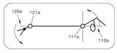
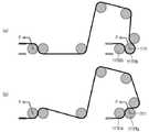
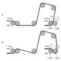
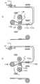
図1Aは、従来の手術用インスツルメントのピッチ動作概念図であり、図1Bは、ヨー動作概念図である。 FIG. 1A is a conceptual diagram of pitch motion of a conventional surgical instrument, and FIG. 1B is a conceptual diagram of yaw motion.
図1Aを参照すれば、従来の手術用インスツルメントのピッチ動作の遂行において、エンドツール120aは、エンドツールの回転中心121aより前方に形成され、操作部110aは、操作部の回転中心111aより後方に形成された状態において、操作部110aを時計回り方向に回転させれば、エンドツール120aも、時計回り方向に回転し、操作部120aを反時計回り方向に回転させれば、エンドツール120aも、反時計回り方向に回転するように形成される。一方、図1Bを参照すれば、従来の手術用インスツルメントのヨー動作の遂行において、エンドツール120aは、エンドツールの回転中心121aより前方に形成され、操作部110aは、操作部の回転中心111aより後方に形成された状態において、操作部110aを時計回り方向に回転させれば、エンドツール120aも、時計回り方向に回転し、操作部120aを反時計回り方向に回転させれば、エンドツール120aも、反時計回り方向に回転するように形成される。この場合、ユーザの左右方向という観点から見たとき、ユーザが操作部110aを左に動かせば、エンドツール120aは、右側に動き、ユーザが操作部110aを右側に動かせば、エンドツール120aは、左に動くことになる。結果として、ユーザの操作方向と、エンドツールの動作方向とが反対になることにより、ユーザをして過ちを誘発させ、ユーザの操作が容易ではないという問題点が存在した。 Referring to FIG. 1A, in performing the pitch motion of a conventional surgical instrument, the
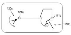
図1Cは、従来の他の手術用インスツルメントのピッチ動作概念図であり、図1Dは、ヨー動作概念図である。 FIG. 1C is a conceptual diagram of pitch motion of other conventional surgical instruments, and FIG. 1D is a conceptual diagram of yaw motion.
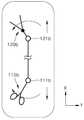
図1Cを参照すれば、従来の手術用インスツルメントのうち一部は、ミラー対称形態に形成され、ピッチ動作の遂行において、エンドツール120bは、エンドツールの回転中心121bより前方に形成され、操作部110bは、操作部の回転中心111bより後方に形成された状態において、操作部110bを時計回り方向に回転させれば、エンドツール120bは、反時計回り方向に回転し、操作部110bを反時計回り方向に回転させれば、エンドツール120bは、時計回り方向に回転するように形成される。この場合、操作部とエンドツールとの回転方向という観点から見たとき、ユーザが操作部110bを回転させる回転方向と、それによるエンドツール120bの回転方向は、互いに反対になる。結果として、ユーザに操作方向の混乱をもたらし、関節の動作が直観的ではなく、ミスを誘発させるという問題点が存在した。また、図1Dを参照すれば、ヨー動作の遂行において、エンドツール120bは、エンドツールの回転中心121bより前方に形成され、操作部110bは、操作部の回転中心111bより後方に形成された状態において、操作部110bを時計回り方向に回転させれば、エンドツール120bは、反時計回り方向に回転し、操作部110bを反時計回り方向に回転させれば、エンドツール120bは、時計回り方向に回転するように形成される。この場合、操作部とエンドツールとの回転方向という観点から見たとき、ユーザが操作部110bを回転させる回転方向と、それによるエンドツール120bの回転方向は、互いに反対になる。結果として、ユーザに操作方向の混乱をもたらし、関節の動作が直観的ではなく、ミスを誘発させるという問題点が存在した。かように、従来の手術用インスツルメントのユーザのピッチ操作またはヨー操作において、ユーザの操作方向とエンドツールの動作方向とが回転方向の観点、または左右方向の観点のうち一つにおいては、互いに一致しない。それは、従来の手術用インスツルメントの関節構成において、エンドツールと操作部との構成が互いに異なるからである。すなわち、エンドツールは、エンドツールの回転中心より前方に形成されているのに対し、操作部は、操作部の回転中心より後方に形成されるからである。かような問題点を解決するために、図1E及び図1Fに図示された本発明の一実施形態による手術用インスツルメントは、エンドツール120cをエンドツールの回転中心121cより前方に形成し、操作部110cも、操作部の回転中心111cより前方に形成し、操作部110cとエンドツール120cとの動作が直観的に一致するようにすることを一特徴とする。かような特性について言い換えて表現すれば、図1A、図1B、図1C及び図1Dのように、操作部が自体の関節に対して、ユーザ側に近くなる(すなわち、エンドツールから遠くなる)構成の既存の例とは異なり、図1E及び図1Fに図示された本発明の一実施形態による手術用インスツルメントは、操作過程のある一瞬間以上では、操作部の少なくとも一部が、自体の関節を基準に、(自体の関節より)エンドツールにさらに近づくことができるように形成されるのである。 Referring to FIG. 1C, some of the conventional surgical instruments are formed in a mirror-symmetrical form, and in performing the pitch motion, the
それについて言い換えて説明すれば、図1A、図1B、図1C及び図1Dのような従来の手術用インスツルメントの場合には、エンドツールが自体の回転中心より前方に位置するのに対し、操作部は、自体の回転中心より後方に形成され、前方が固定された状態で後方を動かす操作部の動作を介して、後方が固定された状態で前方が動くエンドツールを動かすようになるので、構造上、直観的に一致しない構造である。それにより、操作部の操作と、エンドツールの動作とにおいて、左右方向の観点、または回転方向の観点において、不一致が発生し、ユーザに混乱をもたらし、操作部の操作を直観的に迅速に遂行し難くなり、ミスを誘発させるという問題点が存在した。それに対し、本発明の一実施形態による手術用インスツルメントは、エンドツールと操作部とがいずれも後方に形成された回転中心を基準に動くために、構造上、直観的に動作が互いに一致するといえるのである。言い換えて説明すれば、エンドツールの動く部分が後方に形成された回転中心を基準に動くように、操作部の動く部分も、後方に形成された当該回転中心を基準に動くために、構造上、直観的に動作が互いに一致するといえる。それにより、ユーザは、エンドツール側の操縦を直観的に迅速に行うことができ、ミスが誘発される可能性が顕著に減るという長所がある。以下では、かような機能を可能にする具体的なメカニズムについて説明する。 In other words, in the case of conventional surgical instruments such as those in FIGS. 1A, 1B, 1C and 1D, the end tool is located anterior to the center of rotation of itself. The operation unit is formed behind the center of rotation of itself, and through the operation of the operation unit that moves the rear while the front is fixed, the end tool that moves the front while the rear is fixed is moved. , Structurally, it is a structure that does not intuitively match. As a result, there is a discrepancy between the operation of the operation unit and the operation of the end tool from the viewpoint of the left-right direction or the rotation direction, which causes confusion for the user and intuitively and quickly performs the operation of the operation unit. There was a problem that it became difficult to do and caused mistakes. On the other hand, in the surgical instrument according to the embodiment of the present invention, since the end tool and the operation part both move with reference to the rotation center formed rearward, the movements are structurally and intuitively matched with each other. It can be said that. In other words, just as the moving part of the end tool moves with respect to the rotation center formed behind, the moving part of the operation part also moves with reference to the rotation center formed behind, so that it is structurally structural. Intuitively, it can be said that the operations match each other. As a result, the user can intuitively and quickly control the end tool side, which has the advantage of significantly reducing the possibility of inducing mistakes. The specific mechanism that enables such a function will be described below.
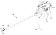
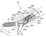
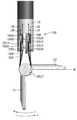
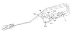
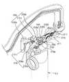
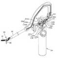
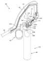
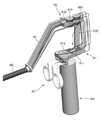
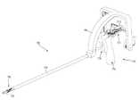
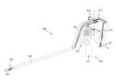
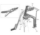
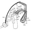
図2は、本発明の第1実施形態による手術用インスツルメントを示す斜視図であり、図3は、図2の手術用インスツルメントの側面図である。 FIG. 2 is a perspective view showing a surgical instrument according to the first embodiment of the present invention, and FIG. 3 is a side view of the surgical instrument of FIG.
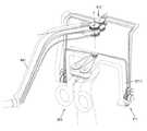
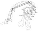
図2及び図3を参照すれば、本発明の第1実施形態による手術用インスツルメント100は、操作部110、エンドツール(end tool)120、動力伝達部130及び連結部140を含む。ここで、連結部140は、中空シャフト(shaft)形状に形成され、その内部に、1本以上のワイヤ(後述する)が収容され、その一端部には、操作部110が結合され、他端部には、エンドツール120が結合され、操作部110とエンドツール120とを連結する役割を行うことができる。ここで、本発明の第1実施形態による手術用インスツルメント100の連結部140は、操作部110側に曲折部141が形成されていることを一特徴とする。このように、連結部140の操作部110側端部が曲折されて形成されることにより、ピッチ操作部111とヨー操作部112とアクチュエーション操作部113とが、エンドツール120の延長線上に形成されたり、延長線に隣接するように形成される。それについて異なる側面から表現すれば、曲折部141が形成する凹部内に、ピッチ操作部111及びヨー操作部112の少なくとも一部が収容されると記述することもできるであろう。かような曲折部141の形状により、操作部110とエンドツール120との形状及び動作がさらに直観的に一致することができる。 With reference to FIGS. 2 and 3, the
一方、曲折部141が形成される平面は、ピッチ平面、すなわち、図2のXZ平面と実質的に同一平面でもある。このように、曲折部141がXZ平面と実質的に同一平面上に形成されることにより、操作部間の干渉が低減する。ここで、エンドツールと操作部との直観的な動作のために、XZ平面だけではなく、他の形態の構成も可能であろうことはということはいうまでもない。 On the other hand, the plane on which the
操作部110は、連結部140の一端部に形成され、医師が直接操ることができるインターフェース、例えば、つまみ形状、スティック形状、レバー形状などでもって具備され、それを医師が操れば、当該インターフェースに連結され、手術患者の体内に挿入されるエンドツール120が、所定の作動を行うことにより、手術を行うことになる。ここで、図2には、操作部110が指を差し込んだ状態で回転させることができる取っ手形状に形成されるように図示されているが、本発明の思想は、それに制限されるものではなく、エンドツール120と連結されてエンドツール120を操作することができる多様な形態の操作部が可能なのである。 The
エンドツール120は、連結部140の他端部に形成され、手術部位に挿入され、手術に必要な動作を遂行する。かようなエンドツール120の一例として、図2に図示されているように、つまみ(grip)動作を遂行するための1対のジョー(jaw)121,122が使用される。ただし、本発明の思想は、それに制限されるものではなく、手術のための多様な装置がエンドツール120として使用されるであろう。例えば、一方片が焼灼器のような構成も、エンドツールとして使用されるであろう。かようなエンドツール120は、操作部110と動力伝達部130とによって連結され、操作部110の駆動力を、動力伝達部130を介して伝達されることにより、つまみ(grip)動作、切断(cutting)動作、縫合(suturing)動作など手術に必要な動作を遂行することになる。 The
ここで、本発明の第1実施形態による手術用インスツルメント100のエンドツール120は、少なくとも2方向以上の方向に回転自在に形成され、例えば、エンドツール120は、図2のY軸を中心に、ピッチ(pitch)運動を行うと共に、図2のZ軸を中心に、ヨー(yaw)運動及びアクチュエーション(actuation)運動を行うようにも形成される。 Here, the
ここで、本発明で使用されるピッチ(pitch)動作とヨー(yaw)動作とアクチュエーション(actuation)動作とのそれぞれについて定義すれば、次の通りである。 Here, if each of the pitch operation, the yaw operation, and the actuation operation used in the present invention is defined, it is as follows.
まず、ピッチ(pitch)動作は、エンドツール120が、連結部140の延長方向(図2のX軸方向)に対して上下方向に回転する運動、すなわち、図2のY軸を中心に回転する動作を意味する。言い換えれば、連結部140の延長方向(図2のX軸方向)に、連結部140から延設されているエンドツール120が、連結部140に対して、Y軸を中心に上下に回転する運動を意味する。次に、ヨー(yaw)動作は、エンドツール120が、連結部140の延長方向(図2のX軸方向)に対して左右方向に回転する動作、すなわち、図2のZ軸を中心に回転する動作を意味する。言い換えれば、連結部140の延長方向(図2のX軸方向)に連結部140から延設されているエンドツール120が、連結部140に対してZ軸を中心に左右に回転する運動を意味する。すなわち、エンドツール120に形成された2つのジョー(jaw)121,122が、Z軸を中心に互いに同一方向に回転する運動を意味する。一方、アクチュエーション(actuation)動作は、エンドツール120が、ヨー(yaw)動作と同一回転軸を中心に回転するが、2つのジョー(jaw)121,122が互いに反対方向に回転しながら、ジョー(jaw)がすぼんだり開いたりする動作を意味する。すなわち、エンドツール120に形成された2つのジョー(jaw)121,122が、Z軸を中心に互いに反対方向に回転する運動を意味する。 First, in the pitch operation, the
動力伝達部130は、操作部110とエンドツール120とを連結し、操作部110の駆動力をエンドツール120に伝達する役割を行い、多数のワイヤ、プーリー、リンク、節、ギアなどを含んでもよい。本発明の一実施形態による手術用インスツルメント100において、動力伝達部130は、ピッチワイヤ130P、第1ジョーワイヤ130J1、第2ジョーワイヤ130J2を含んでもよい。 The
以下では、図2の手術用インスツルメント100の操作部110、エンドツール120、動力伝達部130などについてさらに詳細に説明する。 Hereinafter, the
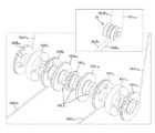
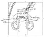
図4及び図5は、図2の手術用インスツルメントのエンドツールを示す斜視図であり、図6Aは、図2の手術用インスツルメントのエンドツールを示す平面図である。 4 and 5 are perspective views showing the end tool of the surgical instrument of FIG. 2, and FIG. 6A is a plan view showing the end tool of the surgical instrument of FIG.
図4、図5及び図6Aを参照すれば、本発明の第1実施形態のエンドツール120は、つまみ(grip)動作を遂行するための1対のジョー(jaw)121,122、すなわち、第1ジョー121と第2ジョー122とを具備する。また、エンドツール120は、第1ジョー(jaw)121の回転運動と係わるJ11プーリー123J11、J12プーリー123J12、J13プーリー123J13、J14プーリー123J14及びJ15プーリー123J15と、第2ジョー(jaw)122の回転運動と係わるJ21プーリー123J21、J22プーリー123J22、J23プーリー123J23、J24プーリー123J24、J25プーリー123J25と、を含む。ここで、第1ジョー121、J11プーリー123J11、J12プーリー123J12、J14プーリー123J14、第2ジョー122、J21プーリー123J21、J22プーリー123J22、J24プーリー123J24は、いずれもエンドツールピッチ回転軸123PAを中心に回転するようにも形成される。 With reference to FIGS. 4, 5 and 6A, the
一方、エンドツール120と結合する連結部140の一端部には、連結部ハブ142が形成される。そして、前述のJ12プーリー123J12、J13プーリー123J13、J14プーリー123J14、J15プーリー123J15と、J22プーリー123J22、J23プーリー123J23、J24プーリー123J24、J25プーリー123J25は、連結部ハブ142に連結される。 On the other hand, a connecting
ここで、図面には、対向しているプーリーが互いに平行に形成されるように図示されているが、本発明の思想は、それに制限されるものではなく、それぞれのプーリーが、エンドツールの構成に適する位置及び大きさで多様に形成されるのである。 Here, although the drawings are shown so that the opposing pulleys are formed parallel to each other, the idea of the present invention is not limited thereto, and each pulley is configured as an end tool. It is formed in various positions and sizes suitable for.
J11プーリー123J11及びJ21プーリー123J21は、互いに対向するように形成され、ジョー回転軸123JAを中心に、互いに独立して回転自在に形成される。ここで、J11プーリー123J11には、第1ジョー(jaw)121が固定結合され、J11プーリー123J11と共に回転し、J21プーリー123J21には、第2ジョー(jaw)122が固定結合され、J21プーリー123J21と共に回転することができる。J11プーリー123J11及びJ21プーリー123J21の回転により、エンドツール120のヨー動作及びアクチュエーション動作が遂行される。すなわち、J11プーリー123J11及びJ21プーリー123J21が同じ方向に回転すれば、ヨー動作が遂行され、J11プーリー123J11及びJ21プーリー123J21が互いに反対方向に回転すれば、アクチュエーション動作が遂行されるのである。 The J11 pulley 123J11 and the J21 pulley 123J21 are formed so as to face each other, and are rotatably formed independently of each other around the jaw rotation shaft 123JA. Here, the first jaw (jaw) 121 is fixedly coupled to the J11 pulley 123J11 and rotates together with the J11 pulley 123J11, and the second jaw (jaw) 122 is fixedly coupled to the J21 pulley 123J21 together with the J21 pulley 123J21. Can rotate. The rotation of the J11 pulley 123J11 and the J21 pulley 123J21 carries out the yaw operation and the actuation operation of the
一方、J11プーリー123J11及びJ21プーリー123J21の一側には、補助プーリーであるJ16プーリー123J16及びJ26プーリー123J26が追加して具備され、かような補助プーリーは、補助プーリー軸123Sを中心に回転自在に形成される。ここで、図面には、J16プーリー123J16及びJ26プーリー123J26が1つの補助プーリー軸123Sを中心に回転するように形成されているが、それぞれの補助プーリーが別途の軸を中心に回転自在に形成されるということはいうまでもない。言い換えれば、補助プーリーであるJ16プーリー123J16は、J11プーリー123J11と、J12プーリー123J12/J14プーリー123J14との間にも配置される。また、補助プーリーであるJ26プーリー123J26は、J21プーリー123J21と、J22プーリー123J22/J24プーリー123J24との間にも配置される。かような補助プーリーについては、追ってさらに詳細に説明する。 On the other hand, on one side of the J11 pulley 123J11 and the J21 pulley 123J21, auxiliary pulleys J16 pulley 123J16 and J26 pulley 123J26 are additionally provided, and such an auxiliary pulley can rotate around the
以下では、J11プーリー123J11の回転と係わる構成要素について説明する。 Hereinafter, the components related to the rotation of the J11 pulley 123J11 will be described.
J11プーリー123J11の一側には、互いに対向するように、J12プーリー123J12及びJ14プーリー123J14が配置される。ここで、J12プーリー123J12及びJ14プーリー123J14は、エンドツールピッチ回転軸123PAを中心に、互いに独立して回転自在に形成される。また、J12プーリー123J12及びJ14プーリー123J14それぞれの一側には、互いに対向するように、J13プーリー123J13及びJ15プーリー123J15が配置される。ここで、J13プーリー123J13及びJ15プーリー123J15は、Y軸方向を中心に、互いに独立して回転自在に形成される。ここで、図面には、J12プーリー123J12、J13プーリー123J13、J14プーリー123J14及びJ15プーリー123J15がいずれもY軸方向を中心に回転自在に形成されるように図示されているが、本発明の思想は、それに制限されるものではなく、各プーリーの回転軸は、その構成に適するように多様な方向に形成されるであろう。 On one side of the J11 pulley 123J11, the J12 pulley 123J12 and the J14 pulley 123J14 are arranged so as to face each other. Here, the J12 pulley 123J12 and the J14 pulley 123J14 are rotatably formed independently of each other around the end tool pitch rotation shaft 123PA. Further, J13 pulley 123J13 and J15 pulley 123J15 are arranged on one side of each of the J12 pulley 123J12 and the J14 pulley 123J14 so as to face each other. Here, the J13 pulley 123J13 and the J15 pulley 123J15 are rotatably formed independently of each other about the Y-axis direction. Here, the drawings show that the J12 pulley 123J12, the J13 pulley 123J13, the J14 pulley 123J14, and the J15 pulley 123J15 are all rotatably formed about the Y-axis direction. , But not limited to it, the axis of rotation of each pulley will be formed in various directions to suit its configuration.
第1ジョーワイヤ130J1は、J13プーリー123J13、J12プーリー123J12、J11プーリー123J11、J16プーリー123J16、J14プーリー123J14、J15プーリー123J15と少なくとも一部が接触するように順に巻かれ、第1ジョーワイヤ130J1が前記プーリーを回転させながら、前記プーリーによって移動することができるように形成される。 The first jaw wire 130J1 is wound in order so that at least a part of the J13 pulley 123J13, the J12 pulley 123J12, the J11 pulley 123J11, the J16 pulley 123J16, the J14 pulley 123J14, and the J15 pulley 123J15 are in contact with each other, and the first jaw wire 130J1 is described above. It is formed so that it can be moved by the pulley while rotating the pulley.
従って、第1ジョーワイヤ130J1が、図6Aの矢印J1R側に引っ張られれば、第1ジョーワイヤ130J1が、J15プーリー123J15、J14プーリー123J14、J16プーリー123J16、J11プーリー123J11、J12プーリー123J12、J13プーリー123J13を回転させ、このとき、J11プーリー123J11が図6Aの矢印R方向に回転しながら、第1ジョー(jaw)121を共に回転させる。 Therefore, if the first jaw wire 130J1 is pulled toward the arrow J1R in FIG. 6A, the first jaw wire 130J1 will have the J15 pulley 123J15, the J14 pulley 123J14, the J16 pulley 123J16, the J11 pulley 123J11, the J12 pulley 123J12, and the J13 pulley 123J13. At this time, the first jaw (jaw) 121 is rotated together while the J11 pulley 123J11 is rotating in the direction of the arrow R in FIG. 6A.
反対に、第1ジョーワイヤ130J1が図6Aの矢印J1L側に引っ張られれば、第1ジョーワイヤ130J1が、J13プーリー123J13、J12プーリー123J12、J11プーリー123J11、J16プーリー123J16、J14プーリー123J14、J15プーリー123J15を回転させ、このとき、J11プーリー123J11が図6Aの矢印L方向に回転しながら、第1ジョー(jaw)121を共に回転させる。 On the contrary, if the first jaw wire 130J1 is pulled toward the arrow J1L in FIG. 6A, the first jaw wire 130J1 becomes the J13 pulley 123J13, J12 pulley 123J12, J11 pulley 123J11, J16 pulley 123J16, J14 pulley 123J14, J15 pulley 123J15. At this time, the first jaw (jaw) 121 is rotated together while the J11 pulley 123J11 is rotating in the direction of the arrow L in FIG. 6A.
以下では、補助プーリー123J16,123J26についてさらに詳細に説明する。 Hereinafter, the auxiliary pulleys 123J16 and 123J26 will be described in more detail.
補助プーリー123J16,123J26は、第1ジョーワイヤ130J1及び第2ジョーワイヤ130J2と接触し、第1ジョーワイヤ130J1及び第2ジョーワイヤ130J2の配置経路を一定程度変更させることにより、第1ジョー121及び第2ジョー122それぞれの回転半径を拡大させる役割を行うことができる。すなわち、図6Bのように、補助プーリーが配置されていない場合、第1ジョー121及び第2ジョー122それぞれは、直角までしか回転することができないが、本発明の一実施形態においては、補助プーリー123J16,123J26を追加して具備することにより、図6Aで見たとき、θほど最大回転角度が大きくなる効果を得ることができる。それは、エンドツール120の2つのジョーがL方向に90゜ほど共にヨー回転した状態で、アクチュエーション動作のために、2つのジョーが開かなければならない動作を可能にする。すなわち、第2ジョー122が、図6Aのように、さらなる角度θほど回転することができるからである。同様に、2つのジョーがR方向にヨー回転した状態でも、アクチュエーション動作が可能である。言い換えれば、補助プーリー123J16,123J26の構成を介して、アクチュエーション動作が可能なヨー回転の範囲を拡大させることができる特徴を有する。それについてさらに詳細に説明すれば、次の通りである。 The auxiliary pulleys 123J16 and 123J26 come into contact with the first jaw wire 130J1 and the second jaw wire 130J2, and the arrangement paths of the first jaw wire 130J1 and the second jaw wire 130J2 are changed to a certain extent to change the arrangement paths of the first jaw wire 130J1 and the second jaw wire 130J2 to a certain extent. It can play a role of expanding the turning radius of each of the two
図6Bを参照すれば、第1ジョーワイヤ130J1は、J11プーリー(図示せず)に固定結合されており、第2ジョーワイヤ130J2は、J21プーリー123J21に固定結合されているために、補助プーリーが配置されていない場合、J11プーリー(図示せず)及びJ21プーリー123J21それぞれは、矢印L方向には、図6BのMラインまでしか回転することができない。言い換えれば、第1ジョーワイヤ130J1とJ11プーリー123J11との固定結合部と、第1ジョーワイヤ130J1とが分離しないほぼ直角方向までしか回転することができない。その場合、第1ジョー121及び第2ジョー122が、図6BのMラインに位置した状態で、アクチュエーション動作を遂行すれば、第1ジョー121は、R方向に開くことができるが、第2ジョー122は、L方向にMライン以上には、回転することができない。従って、第1ジョー121及び第2ジョー122が、一定角度以上ヨー動作を遂行している状態では、アクチュエーション動作が円滑に遂行されないという問題点が存在した。 Referring to FIG. 6B, the first jaw wire 130J1 is fixedly coupled to the J11 pulley (not shown), and the second jaw wire 130J2 is fixedly coupled to the J21 pulley 123J21, so that the auxiliary pulley is When not arranged, each of the J11 pulley (not shown) and the J21 pulley 123J21 can rotate only up to the M line in FIG. 6B in the direction of arrow L. In other words, the fixed coupling portion between the first jaw wire 130J1 and the J11 pulley 123J11 and the first jaw wire 130J1 can rotate only in a substantially right-angled direction in which they are not separated. In that case, if the actuation operation is performed with the
かような問題点を解決するために、本発明の一実施形態による手術用インスツルメント100では、J11プーリー123J11及びJ21プーリー123J21の一側に、補助プーリーであるJ16プーリー123J16及びJ26プーリー123J26を追加して配置することを特徴とする。このように、J16プーリー123J16及びJ26プーリー123J26を配置し、第1ジョーワイヤ130J1及び第2ジョーワイヤ130J2の配置経路を一定程度変更させることにより、第1ジョーワイヤ130J1及び第2ジョーワイヤ130J2の接線方向を変更させ、従って、第2ジョーワイヤ130J2とJ21プーリー123J21との固定結合部を、図6AのNラインまで回転させるのである。すなわち、第2ジョーワイヤ130J2とJ21プーリー123J21との結合部は、J21プーリー123J21とJ26プーリー123J26との共通内接線上に位置するまで回転自在になる。同様に、第1ジョーワイヤ130J1とJ11プーリー123J11との結合部は、J11プーリー123J11とJ16プーリー123J16との共通内接線上に位置するまで回転自在になり、R方向に回転範囲が拡大される。 In order to solve such a problem, in the
かような本発明によって、第1ジョー121及び第2ジョー122の回転半径が大きくなることにより、正常な開閉アクチュエーション動作が遂行されるヨー動作範囲が広くなる効果を得ることができる。 According to the present invention, by increasing the radius of gyration of the
次に、J21プーリー123J21の回転と係わる構成要素について説明する。 Next, the components related to the rotation of the J21 pulley 123J21 will be described.
J21プーリー123J21の一側には、互いに対向するように、J22プーリー123J22及びJ24プーリー123J24が配置される。ここで、J22プーリー123J22及びJ24プーリー123J24は、エンドツールピッチ回転軸123PA側を中心に、互いに独立して回転自在に形成される。また、J22プーリー123J22及びJ24プーリー123J24それぞれの一側には、互いに対向するように、J23プーリー123J23及びJ25プーリー123J25が配置される。ここで、J23プーリー123J23及びJ15プーリー123J25は、Y軸方向を中心に、互いに独立して回転自在に形成される。ここで、図面には、J22プーリー123J22、J23プーリー123J23、J24プーリー123J24及びJ25プーリー123J25がいずれもY軸方向を中心に回転自在に形成されるように図示されているが、本発明の思想は、それに制限されるものではなく、各プーリーの回転軸は、その構成に適するように多様な方向に形成されるであろう。 On one side of the J21 pulley 123J21, the J22 pulley 123J22 and the J24 pulley 123J24 are arranged so as to face each other. Here, the J22 pulley 123J22 and the J24 pulley 123J24 are rotatably formed independently of each other around the end tool pitch rotation shaft 123PA side. Further, J23 pulley 123J23 and J25 pulley 123J25 are arranged on one side of each of the J22 pulley 123J22 and the J24 pulley 123J24 so as to face each other. Here, the J23 pulley 123J23 and the J15 pulley 123J25 are rotatably formed independently of each other about the Y-axis direction. Here, the drawings show that the J22 pulley 123J22, the J23 pulley 123J23, the J24 pulley 123J24, and the J25 pulley 123J25 are all rotatably formed about the Y-axis direction. , But not limited to it, the axis of rotation of each pulley will be formed in various directions to suit its configuration.
第2ジョーワイヤ130J2は、J23プーリー123J23、J22プーリー123J22、J21プーリー123J21、J26プーリー123J26、J24プーリー123J24、J25プーリー123J25と少なくとも一部が接触するように順に巻かれ、第2ジョーワイヤ130J2が前記プーリーを回転させながら、前記プーリーによって移動することができるように形成される。 The second jaw wire 130J2 is wound in order so that at least a part of the second jaw wire 130J2 comes into contact with the J23 pulley 123J23, the J22 pulley 123J22, the J21 pulley 123J21, the J26 pulley 123J26, the J24 pulley 123J24, and the J25 pulley 123J25. It is formed so that it can be moved by the pulley while rotating the pulley.
従って、第2ジョーワイヤ130J2が図6Aの矢印J2R側に引っ張られれば、第2ジョーワイヤ130J2が、J23プーリー123J23、J22プーリー123J22、J21プーリー123J21、J26プーリー123J26、J24プーリー123J24、J25プーリー123J25を回転させ、このとき、J21プーリー123J21が、図6Aの矢印R方向に回転しながら、第2ジョー(jaw)122を共に回転させる。 Therefore, if the second jaw wire 130J2 is pulled toward the arrow J2R in FIG. 6A, the second jaw wire 130J2 will pull the J23 pulley 123J23, the J22 pulley 123J22, the J21 pulley 123J21, the J26 pulley 123J26, the J24 pulley 123J24, and the J25 pulley 123J25. At this time, the J21 pulley 123J21 rotates the second jaw (jaw) 122 together while rotating in the direction of the arrow R in FIG. 6A.
反対に、第2ジョーワイヤ130J2が、図6Aの矢印J2L側に引っ張られれば、第2ジョーワイヤ130J2が、J25プーリー123J25、J24プーリー123J24、J26プーリー123J26、J21プーリー123J21、J22プーリー123J22、J23プーリー123J23を回転させ、このとき、J21プーリー123J21が図6Aの矢印L方向に回転しながら、第2ジョー(jaw)122を共に回転させる。 Conversely, if the second jaw wire 130J2 is pulled toward the arrow J2L in FIG. 6A, the second jaw wire 130J2 will have the J25 pulley 123J25, J24 pulley 123J24, J26 pulley 123J26, J21 pulley 123J21, J22 pulley 123J22, J23 pulley. The 123J23 is rotated, and at this time, the second jaw (jaw) 122 is rotated together while the J21 pulley 123J21 is rotating in the direction of the arrow L in FIG. 6A.
一方、第1ジョーワイヤ130J1の一端部は、図6Aの矢印J1R側に引っ張られ、同時に第1ジョーワイヤ130J1の他端部は、図6Aの矢印J1L側に引っ張られれば、(すなわち、第1ジョーワイヤ130J1の両端部がいずれも引っ張られれば)、図5のように、第1ジョーワイヤ130J1は、エンドツールピッチ回転軸123PAを中心に回転することができるJ12プーリー123J12とJ14プーリー123J14との下方に巻かれているために、第1ジョーワイヤ130J1が固定結合されているJ11プーリー123J11、第1ジョー121、ジョー回転軸123JA、エンドツールハブ123a、及びそれらと連結された第2ジョー122などは、全体的にエンドツールピッチ回転軸123PAを中心に、反時計回り方向に共に回転することになり、結果として、エンドツール120が下方に回転しながら、ピッチ運動を行うことになる。このとき、第2ジョー122、及びそれに固定結合された第2ジョーワイヤ130J2は、エンドツールピッチ回転軸123PAを中心に回転することができるJ22プーリー123J22とJ24プーリー123J24との上方に巻かれているために、第2ジョーワイヤ130J2の両端部は、それぞれJ2L、J2Rの反対方向に移動することになる。 On the other hand, if one end of the first jaw wire 130J1 is pulled toward the arrow J1R in FIG. 6A and at the same time the other end of the first jaw wire 130J1 is pulled toward the arrow J1L in FIG. 6A (that is, the first jaw wire 130J1). (If both ends of the jaw wire 130J1 are pulled), as shown in FIG. 5, the first jaw wire 130J1 has a J12 pulley 123J12 and a J14 pulley 123J14 that can rotate about the end tool pitch rotation shaft 123PA. J11 pulley 123J11 to which the first jaw wire 130J1 is fixedly coupled because it is wound downward, the
反対に、第2ジョーワイヤ130J2の一端部は、図6Aの矢印J2R側に引っ張られ、同時に第2ジョーワイヤ130J2の他端部は、図6Aの矢印J2L側に引っ張られれば、図5のように、第2ジョーワイヤ130J2は、エンドツールピッチ回転軸123PAを中心に回転することができるJ22プーリー123J22とJ24プーリー123J24との上方に巻かれているために、第2ジョーワイヤ130J2が固定結合されているJ21プーリー123J21、第2ジョー122、ジョー回転軸123JA、エンドツールハブ123a、及びそれらと連結された第1ジョー121などは、全体的にエンドツールピッチ回転軸123PAを中心に、時計回り方向に共に回転することになり、結果として、エンドツール120が上方に回転しながら、ピッチ運動を行うことになる。このとき、第1ジョー121、及びそれに固定結合された第1ジョーワイヤ130J1は、エンドツールピッチ回転軸123PAを中心に回転することができるJ12プーリー123J12とJ14プーリー123J14の下方に巻かれているために、第1ジョーワイヤ130J1の両端部は、それぞれJ1L、J1Rの反対方向に移動することになる。 On the contrary, if one end of the second jaw wire 130J2 is pulled toward the arrow J2R side of FIG. 6A and at the same time the other end of the second jaw wire 130J2 is pulled toward the arrow J2L side of FIG. 6A, as shown in FIG. Since the second jaw wire 130J2 is wound above the J22 pulley 123J22 and the J24 pulley 123J24 that can rotate around the end tool pitch rotation shaft 123PA, the second jaw wire 130J2 is fixedly coupled. The J21 pulley 123J21, the
一方、本発明の手術用インスツルメント100bのエンドツール120は、ピッチプーリー123Pをさらに具備し、操作部110は、ピッチワイヤエンドプーリー115Pをさらに具備し、動力伝達部130は、ピッチワイヤ130Pをさらに具備することができる。詳細には、エンドツール120のピッチプーリー123Pは、エンドツールピッチ回転軸123PAを中心に回転自在であり、エンドツールハブ123aに固定結合されるようにも形成される。一方、操作部のピッチプーリーは、ピッチ回転軸を中心に回転自在であり、ピッチ操作部(図示せず)に固定結合されるようにも形成される。また、ピッチワイヤ130Pは、エンドツール120のピッチプーリー123Pと操作部のピッチプーリーとを連結する役割を行うことができる。 On the other hand, the
従って、ユーザが、操作部110の第1取っ手114を手にしている状態で、ピッチ回転軸1111を中心に、第1取っ手114を回転させれば、第1取っ手114と結合されたピッチプーリーが、ピッチ回転軸1111を中心に回転し、ピッチプーリーの回転は、ピッチワイヤ130Pを介して、エンドツール120のピッチプーリー123Pに伝達され、ピッチプーリー123Pも共に回転することになり、結果として、エンドツール120が回転しながら、ピッチ運動を行うことになるのである。 Therefore, if the user rotates the
すなわち、本発明の第1実施形態による手術用インスツルメント100は、エンドツール120のピッチプーリー123P、操作部110のピッチワイヤエンドプーリー115P、及び動力伝達部130のピッチワイヤ130Pを具備し、ピッチ操作部111のピッチ動作の駆動力がさらに完璧にエンドツール120に伝達されるようにすることにより、動作信頼性を向上させることができる。 That is, the
図6Cは、エンドツールとワイヤとの結合構造の一変形例を示す図面である。 FIG. 6C is a drawing showing a modified example of the coupling structure of the end tool and the wire.
図6Cを参照すれば、J21プーリー123J21に第2ジョーワイヤ130J2が結合されるにおいて、J21プーリー123J21を基準に、第2ジョーワイヤ130J2を2本のワイヤ、第2ジョーワイヤR130J2Rと第2ジョーワイヤL130J2Lとに分割した後、各ワイヤ130J2R,130J2Lの一端をそれぞれJ21プーリー123J21に結合する。すなわち、第2ジョーワイヤR130J2Rの一端部は、J21プーリー123J21の第1結合部123J21Rに結合し、第2ジョーワイヤL130J2Lの一端部は、J21プーリー123J21の第2結合部123J21Lに結合することになる。 Referring to FIG. 6C, when the second jaw wire 130J2 is coupled to the J21 pulley 123J21, the second jaw wire 130J2 is referred to as two wires, the second jaw wire R130J2R and the second jaw wire with reference to the J21 pulley 123J21. After dividing into L130J2L, one end of each wire 130J2R and 130J2L is coupled to the J21 pulley 123J21, respectively. That is, one end of the second jaw wire R130J2R is coupled to the first coupling portion 123J21R of the J21 pulley 123J21, and one end of the second jaw wire L130J2L is coupled to the second coupling portion 123J21L of the J21 pulley 123J21. ..
このとき、J21プーリー123J21の各結合部123J21R,123J21Lの位置は、各ワイヤ130J2R,130J2Lが互いに重なるようにする位置である。それを介して、図6Bにおいて、第2ジョー122の回転半径が90゜に制限されるところを拡張させ、結果として、図6Aでのように、第2ジョー122の回転半径を拡張させることができる。 At this time, the positions of the coupling portions 123J21R and 123J21L of the J21 pulley 123J21 are positions so that the wires 130J2R and 130J2L overlap each other. Through this, in FIG. 6B, the radius of gyration of the
第1ジョーワイヤ130J1も、前記方法と同一に、J11プーリー123J11に固定結合されるようにし、結果として、第1ジョー121の回転半径を拡張させることができる。それを介して、正常な開閉アクチュエーション動作が遂行されるヨー動作範囲が広くなる効果を有することができる。 The first jaw wire 130J1 is also fixedly coupled to the J11 pulley 123J11 in the same manner as in the above method, and as a result, the turning radius of the
図6Dは、エンドツールとワイヤとの結合構造の他の一変形例を示す図面である。 FIG. 6D is a drawing showing another modified example of the connecting structure of the end tool and the wire.
図6Dを参照すれば、J11プーリー123J11に第1ジョーワイヤ130J1が結合されるにおいて、J11プーリー123J11を基準に、第1ジョーワイヤ130J1を2本のワイヤ、第1ジョーワイヤR130J1Rと第1ジョーワイヤL130J1Lとに分割した後、各ワイヤ130J1R,130J1Lの一端を、それぞれJ11プーリー123J11の結合部材123J11Cに結合する。このとき、結合部材123J21Cは、J11プーリー123J11において、第1ジョー121の反対側に形成され、結合部材123J21Cの一側には、第1ジョーワイヤR130J1Rの一端部が結合され、結合部材123J21Cの他側には、第1ジョーワイヤL130J1Lの一端部が結合される。 Referring to FIG. 6D, when the first jaw wire 130J1 is coupled to the J11 pulley 123J11, the first jaw wire 130J1 is referred to as two wires, the first jaw wire R130J1R and the first jaw wire, based on the J11 pulley 123J11. After dividing into L130J1L, one end of each wire 130J1R and 130J1L is coupled to the coupling member 123J11C of the J11 pulley 123J11, respectively. At this time, the coupling member 123J21C is formed on the opposite side of the
このとき、J11プーリー123J11の結合部材123J21Cの位置は、各ワイヤ130J1R,130J1Lを、半回りさらに巻かれる位置である。それを介して、図6Bにおいて、第2ジョー122の回転半径が90゜に制限されるところを拡張させ、結果として、図6Aでのように、第2ジョー122の回転半径を拡張させることができる。 At this time, the position of the coupling member 123J21C of the J11 pulley 123J11 is a position where the wires 130J1R and 130J1L are further wound half a turn. Through this, in FIG. 6B, the radius of gyration of the
第2ジョーワイヤ130J2も、前記方法と同一に、J21プーリー123J21に固定結合されるようにし、結果として、第2ジョー122の回転半径を拡張させることができる。それを介して、正常な開閉アクチュエーション動作が遂行されるヨー動作範囲が広くなる効果を有することができる。 The second jaw wire 130J2 is also fixedly coupled to the J21 pulley 123J21 in the same manner as described above, and as a result, the turning radius of the
(操作部)
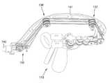
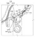
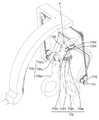
図7Aは、図2の手術用インスツルメントの操作部を示す斜視図であり、図7Bは、図7Aを後方から見た斜視図である。(Operation unit)
FIG. 7A is a perspective view showing an operation unit of the surgical instrument of FIG. 2, and FIG. 7B is a perspective view of FIG. 7A as viewed from the rear.
図2ないし図7A及び図7Bを参照すれば、本発明の第1実施形態による手術用インスツルメント100の操作部110は、ユーザが把持することができる第1取っ手114と、エンドツール120のアクチュエーション運動を制御するアクチュエーション操作部113と、エンドツール120のヨー運動を制御するヨー操作部112と、エンドツール120のピッチ運動を制御するピッチ操作部111と、を含む。 With reference to FIGS. 2 to 7A and 7B, the
まず、図2の手術用インスツルメント100の使用状態を例示すれば、ユーザは、手の平で、第1取っ手114を手にしている状態において、第1取っ手114をY軸(すなわち、ピッチ回転軸1111)を中心に回転させてピッチ動作を遂行し、第1取っ手114をZ軸(すなわち、ヨー回転軸1121)を中心に回転させてヨー動作を遂行することができる。また、ユーザは、親指と人差し指とをアクチュエーション操作部113に差し入れた状態において、アクチュエーション操作部113を回転させ、アクチュエーション動作を遂行することができる。 First, to illustrate the usage state of the
ここで、本発明の第1実施形態による手術用インスツルメント100は、操作部110を、連結部140に対して、いずれか一方向に回転させれば、エンドツール120が、操作部110の操作方向と直観的に同一方向に回転することを一特徴とする。言い換えれば、操作部110の第1取っ手114を、いずれか一方向に回転させれば、エンドツール120も、前記一方向と直観的に同一方向に回転し、ピッチ運動またはヨー運動を行うのである。ここで、直観的に同一方向ということは、操作部110を把持しているユーザの指の移動方向と、エンドツール120の末端部の移動方向とが実質的に同一方向をなすことであると敷衍説明することができる。ここで、同一方向とは、三次元座標上で完璧に一致する方向ではなくともよく、例えば、ユーザの指が左に移動すれば、エンドツール120の末端部も左に移動し、ユーザの指が下に移動すれば、エンドツール120の末端部も、下に移動する程度の同一性であると理解すればよい。 Here, in the
そして、そのために、本発明の第1実施形態による手術用インスツルメント100は、操作部110とエンドツール120とが連結部140の延長軸(X軸)に垂直である平面を基準に、同一方向に形成されることを一特徴とする。すなわち、図2のYZ平面を基準に見たとき、操作部110は、+X軸方向に延設されており、同時にエンドツール120も、+X軸方向に延設されているのである。それについて言い換えて表現すれば、連結部140の一端部でのエンドツール120の形成方向と、連結部140の他端部での操作部110の形成方向とが、YZ平面を基準に同一方向であるとすることもできるのである。または、それについて言い換えて表現すれば、操作部110が、それを把持するユーザの体から遠くなる方向、すなわち、エンドツール120が形成された方向に形成されたということもできるのである。すなわち、アクチュエーション動作、ヨー動作、ピッチ動作のために、ユーザが把持して動かす第1取っ手114、アクチュエーション回転部1132a,1132bなどは、各動作を遂行するために動く部分が、当該動作のための各関節の回転中心より+X軸方向に延設されている。それを介して、エンドツール120の動く部分が、当該動作のための各関節の回転中心より+X軸方向に延設されているところと同一に、操作部110を構成することができ、図1を介して説明したように、ユーザの操作方向と、エントツールの動作方向とが、回転方向の観点と、左右方向の観点との二つとも一致することになり、結果として、直観的に同一操作が可能となる。 For that purpose, the
詳細には、従来の手術用インスツルメントの場合、ユーザが、操作部を操作する方向と、エンドツールの実際作動方向とが互いに異なっており、直観的に一致しないために、手術者の立場で直観的な作動が容易ではなく、エンドツールが所望方向に動くように熟練するのに長年の時間が必要となり、場合によっては、誤動作が発生し、患者に被害を与えることにもなるという問題点が存在した。 Specifically, in the case of conventional surgical instruments, the operator's position is that the direction in which the user operates the operation unit and the actual operating direction of the end tool are different from each other and do not intuitively match. The problem is that it is not easy to operate intuitively, it takes many years to master the end tool to move in the desired direction, and in some cases, it may malfunction and damage the patient. There was a point.
かような問題点を解決するために、本発明の第1実施形態による手術用インスツルメント100は、操作部110の操作方向と、エンドツール120の作動方向とが直観的に同一方向になるようにし、そのために、操作部110は、エンドツール120のように、アクチュエーション動作、ヨー動作、ピッチ動作のために、実際に動くことになる部分が、各動作の当該関節の回転中心より+X軸方向に延設されることを一特徴とする。それについてさらに詳細に説明すれば、次の通りである。 In order to solve such a problem, in the
第1取っ手114は、ユーザが手で把持することができるように形成され、特に、ユーザが、自分の手の平で、第1取っ手114を握ることができるようにも形成される。そして、第1取っ手114上には、アクチュエーション操作部113及びヨー操作部112が形成され、ヨー操作部112の一側には、ピッチ操作部111が形成される。そして、ピッチ操作部111の他端部は、連結部140の曲折部141に連結される。 The
アクチュエーション操作部113は、第1アクチュエーション操作部113aと、第2アクチュエーション操作部113bとを含む。第1アクチュエーション操作部113aは、第1アクチュエーション回転軸1131a、第1アクチュエーション回転部1132a、第1アクチュエーションプーリー113P1、第1アクチュエーションギア1134aを含む。第2アクチュエーション操作部113bは、第2アクチュエーション回転軸1131b、第2アクチュエーション回転部1132b、第2アクチュエーションプーリー113P2、第2アクチュエーションギア1134bを含む。ここで、第1アクチュエーション回転部1132aと、第2アクチュエーション回転部1132bは、第2取っ手として動作することができる。 The
ここで、アクチュエーション回転軸1131a,1131bは、連結部140が形成されているXY平面と所定の角度をなすようにも形成される。例えば、アクチュエーション回転軸1131a,1131bは、Z軸と平行な方向に形成され、この状態で、ピッチ操作部111またはヨー操作部112が回転する場合、アクチュエーション操作部113の座標系は、相対的に変わることができる。ここで、本発明の思想は、それに制限されるものではなく、人体工学的(ergonomic)設計によって、アクチュエーション操作部113を把持するユーザの手構造に適するように、アクチュエーション回転軸1131a,1131bは、多様な方向に形成されるということはいうまでもない。 Here, the
一方、第1アクチュエーション回転部1132a、第1アクチュエーションプーリー113P1、第1アクチュエーションギア1134aは、互いに固定結合され、第1アクチュエーション回転軸1131aを中心に、共に回転自在に形成される。ここで、第1アクチュエーションプーリー113P1は、1つのプーリーによっても構成され、互いに固定結合された2つのプーリーによっても構成される。 On the other hand, the first
同様に、第2アクチュエーション回転部1132b、第2アクチュエーションプーリー113P2、第2アクチュエーションギア1134bは、互いに固定結合され、第2アクチュエーション回転軸1131bを中心に、共に回転自在に形成される。ここで、第2アクチュエーションプーリー113P2は、1つのプーリーによっても構成され、互いに固定結合された2つのプーリーによっても構成される。 Similarly, the second
ここで、第1アクチュエーションギア1134aと第2アクチュエーションギア1134bは、互いに噛み合うように形成され、いずれか一側が回転すれば、互いに反対方向に共に回転するようにも形成される。 Here, the
ヨー操作部112は、ヨー回転軸1121と、第1ジョー・ヨープーリー112P1と、第2ジョー・ヨープーリー112P2と、ヨーフレーム(yaw frame)1123と、を含んでもよい。また、ヨー操作部112は、第1ジョー・ヨープーリー112P1の一側に形成された第1ジョー・ヨー補助プーリー112S1と、第2ジョー・ヨープーリー112P2の一側に形成された第2ジョー・ヨー補助プーリー112S2と、をさらに含んでもよい。ここで、第1ジョー・ヨー補助プーリー112S1と、第2ジョー・ヨー補助プーリー112S2は、後述するピッチフレーム1113にも結合される。 The
ここで、図面には、ヨー操作部112が、第1ジョー・ヨープーリー112P1と、第2ジョー・ヨープーリー112P2とを含み、第1ジョー・ヨープーリー112P1と、第2ジョー・ヨープーリー112P2は、それぞれ互いに対向するように形成されて独立して回転自在な2つのプーリーを具備するように図示されているが、本発明の思想は、それに制限されるものではない。すなわち、互いに直径が同一であるか、あるいは異なる1以上のプーリーが、ヨー操作部112の構成によって具備されもよい。 Here, in the drawing, the
詳細には、第1取っ手114上で、アクチュエーション操作部113の一側には、ヨー回転軸1121が形成される。このとき、第1取っ手114は、ヨー回転軸1121を中心に回転自在に形成される。 Specifically, on the
ここで、ヨー回転軸1121は、連結部140が形成されているXY平面と、所定の角度をなすようにも形成される。例えば、ヨー回転軸1121は、Z軸と平行な方向に形成され、この状態において、ピッチ操作部111が回転する場合、前述のように、ヨー回転軸1121の座標系は、相対的に変わる。ここで、本発明の思想は、それに制限されるものではなく、人体工学的(ergonomic)設計によって、操作部110を把持するユーザの手構造に適するように、ヨー回転軸1121は、多様な方向に形成されるということはいうまでもない。 Here, the
一方、第1ジョー・ヨープーリー112P1と、第2ジョー・ヨープーリー112P2は、ヨー回転軸1121を中心に回転自在に、ヨー回転軸1121に結合する。そして、第1ジョー・ヨープーリー112P1には、第1ジョーワイヤ130J1が巻かれ、第2ジョー・ヨープーリー112P2には、第2ジョーワイヤ130J2が巻かれる。このとき、第1ジョー・ヨープーリー112P1と、第2ジョー・ヨープーリー112P2は、それぞれ互いに対向するように形成され、独立して回転自在な2つのプーリーによっても構成される。従って、巻かれて入っていくワイヤと、巻かれて出てくるワイヤとが、分離されたプーリーにそれぞれ巻かれ、互いに干渉を与えないで動作することができる。 On the other hand, the first jaw yaw pulley 112P1 and the second jaw yaw pulley 112P2 are rotatably coupled to the
ヨーフレーム1123は、第1取っ手114、ヨー回転軸1121、第1アクチュエーション回転軸1131a、第2アクチュエーション回転軸1131bを連結し、第1取っ手114とヨー操作部112とアクチュエーション操作部113とがヨー回転軸1121を中心に一体回転する。 The
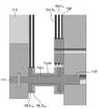
ピッチ操作部111は、ピッチ回転軸1111と、第1ジョー・ピッチプーリーa 111P1aと、第1ジョー・ピッチプーリーb 111P1bと、第2ジョー・ピッチプーリーa 111P2aと、第2ジョー・ピッチプーリーb 111P2bと、ピッチフレーム(pitch frame)1113とを含んでもよい。また、ピッチ操作部111は、第1ジョー・ピッチプーリーa 111P1aの一側に形成された第1ジョー・ピッチ補助プーリーa 111S1aと、第1ジョー・ピッチプーリーb 111P1bの一側に形成された第1ジョー・ピッチ補助プーリーb 111S1bと、第2ジョー・ピッチプーリーa 111P2aの一側に形成された第2ジョー・ピッチ補助プーリーa 111S2aと、第2ジョー・ピッチプーリーb 111P2bの一側に形成された第2ジョー・ピッチ補助プーリーb 111S2bと、をさらに含んでもよい。ピッチ操作部111は、ピッチ回転軸1111を介して、連結部140の曲折部141に連結される。 The
詳細には、ピッチフレーム1113は、ピッチ操作部111のベースフレームになり、一端部に、ヨー回転軸1121が回転自在に結合される。すなわち、ヨーフレーム1123は、ピッチフレーム1113に対して、ヨー回転軸1121を中心に回転自在に形成される。 Specifically, the
前述のように、ヨーフレーム1123は、第1取っ手114、ヨー回転軸1121、第1アクチュエーション回転軸1131a、第2アクチュエーション回転軸1131bを連結し、またヨーフレーム1123は、ピッチフレーム1113と連結されるために、ピッチフレーム1113がピッチ回転軸1111を中心に回転すれば、ピッチフレーム1113と連結されたヨーフレーム1123、第1取っ手114、ヨー回転軸1121、第1アクチュエーション回転軸1131a、第2アクチュエーション回転軸1131bが共に回転することになる。すなわち、ピッチ操作部111が、ピッチ回転軸1111を中心に回転すれば、アクチュエーション操作部113及びヨー操作部112が、ピッチ操作部111と共に回転するのである。言い換えれば、ユーザが、第1取っ手114をピッチ回転軸1111を中心にピッチ回転させれば、アクチュエーション操作部113、ヨー操作部112及びピッチ操作部111が共に動くことになる。 As described above, the
ピッチフレーム1113には、ピッチ回転軸1111と、第1ジョー・ピッチプーリーa 111P1aと、第1ジョー・ピッチプーリーb 111P1bと、第2ジョー・ピッチプーリーa 111P2aと、第2ジョー・ピッチプーリーb 111P2bとが結合する。このとき、第1ジョー・ピッチプーリーa 111P1aと、第1ジョー・ピッチプーリーb 111P1bと、第2ジョー・ピッチプーリーa 111P2aと、第2ジョー・ピッチプーリーb 111P2bは、ピッチ回転軸1111を中心に回転自在に、ピッチ回転軸1111に結合する。 The
ここで、第1ジョー・ピッチプーリーa 111P1aと第1ジョー・ピッチプーリーb 111P1bは、互いに対向するように形成され、独立して回転自在に形成される。従って、巻かれて入っていくワイヤと、巻かれて出てくるワイヤとが、分離されたプーリーにそれぞれ巻かれ、互いに干渉を与えずに動作することができる。同様に、第2ジョー・ピッチプーリーa 111P2a及び第2ジョー・ピッチプーリーb 111P2bも、互いに対向するように形成され、独立して回転自在に形成される。従って、巻かれて入っていくワイヤと、巻かれて出てくるワイヤとが、分離されたプーリーにそれぞれ巻かれ、互いに干渉を与えずに動作することができる。 Here, the first jaw pitch pulley a 111P1a and the first jaw pitch pulley b 111P1b are formed so as to face each other and are independently rotatably formed. Therefore, the wire that is wound in and the wire that is wound out can be wound around the separated pulleys and operate without interfering with each other. Similarly, the second jaw pitch pulley a 111P2a and the second jaw pitch pulley b 111P2b are also formed so as to face each other and are independently rotatably formed. Therefore, the wire that is wound in and the wire that is wound out can be wound around the separated pulleys and operate without interfering with each other.
図7Bを参考すれば、ピッチワイヤエンドプーリー115Pは、ピッチフレーム1113と固定結合され、共に回転するように形成される。そして、ピッチワイヤ130Pは、ピッチワイヤ補助プーリー115S、ピッチワイヤエンドプーリー115Pを経て、ピッチフレーム1113に固定結合される。結果として、ピッチ回転により、ピッチフレーム1113、ピッチワイヤエンドプーリー115Pは、ピッチ回転軸1111を中心に、共に回転することができる。 With reference to FIG. 7B, the pitch
ピッチワイヤ130Pの動作は、次の通りである。 The operation of the
エンドツール120には、ピッチプーリー123Pがエンドツールハブ123aに固定結合されて形成され、操作部110には、ピッチワイヤエンドプーリー115Pが形成され、それらは、ピッチワイヤ130Pで互いに連結され、操作部110のピッチ操作により、エンドツールのピッチ動作がさらに容易に遂行される。ここで、ピッチワイヤ130Pの両端の部分は、それぞれ当該ピッチワイヤ補助プーリー115Sと、ピッチワイヤエンドプーリー115Pとを経て、ピッチフレーム1113に固定結合され、各ピッチワイヤエンドプーリー115Pも、ピッチフレーム1113に固定結合される。すなわち、操作部のピッチ回転により、ピッチフレーム1113とピッチワイヤエンドプーリー115Pとがピッチ回転軸1111を中心に、共に回転することになり、結果として、ピッチワイヤ130Pの両端も、互いに反対方向に移動することになり、第1ジョーワイヤ130J1及び第2ジョーワイヤ130J2によるエンドツールのピッチ動作とは別途に、追加のピッチ回転の動力を伝達することができる。 The
第1取っ手114と、ピッチ操作部111、ヨー操作部112、アクチュエーション操作部113それぞれとの連結関係を整理すれば、次の通りである。第1取っ手114上には、アクチュエーション回転軸1131a,1131bと、ヨー回転軸1121と、ピッチ回転軸1111とが形成される。このとき、アクチュエーション回転軸1131a,1131bは、第1取っ手114上に直接形成されるので、第1取っ手114とアクチュエーション操作部113は、直接連結されている。一方、ヨー回転軸1121は、第1取っ手114上に直接形成されるので、第1取っ手114とヨー操作部112は、直接連結されている。一方、ピッチ操作部111は、ヨー操作部112の一側に、ヨー操作部112と連結されるように形成されるために、ピッチ操作部111は、第1取っ手114と直接に連結されず、ピッチ操作部111と第1取っ手114は、ヨー操作部112を介して間接的に連結されるようにも形成される。 The connection relationship between the
続けて図面を参照すれば、本発明の第1実施形態による手術用インスツルメント100において、ピッチ操作部111とエンドツール120とが、同一であるか、あるいは平行な軸(X軸)上にも形成される。すなわち、連結部140の曲折部141の一端部には、ピッチ操作部111のピッチ回転軸1111が形成され、連結部140の他端部には、エンドツール120が形成されるのである。 Subsequently, referring to the drawings, in the
そして、連結部140の中間に、特に、曲折部141部分には、ワイヤの経路を変更またはガイドする1以上の仲介プーリーMPが配置される。かような仲介プーリーMPに、ワイヤの少なくとも一部が巻かれるように形成され、ワイヤの経路をガイドすることにより、曲折部141の曲折された形状に沿って、ワイヤが配置されるのである。 Then, one or more intermediary pulley MPs for changing or guiding the path of the wire are arranged in the middle of the connecting
ここで、図面には、連結部140は、曲折部141を具備して所定の曲率を有するように湾曲されて形成されるように図示されているが、本発明の思想は、それに制限されるものではなく、連結部140が、必要によって直線に形成されたり、または1回以上曲折されて形成されもし、かような場合にも、ピッチ操作部111とエンドツール120は、実質的に、同一または平行な軸上に形成されるといえるのである。また、図3には、ピッチ操作部111とエンドツール120とがX軸と平行な軸上にそれぞれ形成されるように図示されているが、本発明の思想は、それに制限されるものではなく、ピッチ操作部111とエンドツール120とが互いに異なる軸上に形成されもするのである。 Here, in the drawings, the connecting
本実施形態でのアクチュエーション動作、ヨー動作、ピッチ動作について説明すれば、次の通りである。 The actuation operation, yaw operation, and pitch operation in this embodiment will be described as follows.
まず、アクチュエーション動作は、次の通りである。 First, the actuation operation is as follows.
ユーザが、第1アクチュエーション回転部1132aに人差し指を差し込み、第2アクチュエーション回転部1132bに親指を差し込んだ状態で、いずれか一方の指または両指をいずれも利用して、アクチュエーション回転部1132a 1132bを回転させれば、第1アクチュエーション回転部1132aと固定結合された第1アクチュエーションプーリー113P1及び第1アクチュエーションギア1134aは、第1アクチュエーション回転軸1131aを中心に回転し、第2アクチュエーション回転部1132bと固定結合された第2アクチュエーションプーリー1133b及び第2アクチュエーションギア1134bが、第2アクチュエーション回転軸1131bを中心に回転する。このとき、第1アクチュエーションプーリー113P1と第2アクチュエーションプーリー113P2は、互いに反対方向に回転することになり、従って、第1アクチュエーションプーリー113P1に一端部が固定結合されて巻かれた第1ジョーワイヤ130J1、及び第2アクチュエーションプーリー113P2に一端部が固定結合されて巻かれた第2ジョーワイヤ130J2も、互いに反対方向に移動することになる。そして、かような回転力が、動力伝達部130を介して、エンドツール120に伝達され、エンドツール120の2つのジョー(jaw)121,122がアクチュエーション動作を遂行する。ここで、アクチュエーション動作とは、前述のように、2つのジョー(jaw)121,122が互いに反対方向に回転しながら、ジョー(jaw)121,122を開閉する動作を意味する。すなわち、アクチュエーション操作部113のアクチュエーション回転部1132a 1132bを、互いに近くなる方向に回転させれば、第1ジョー(jaw)121は、反時計回り方向に回転し、第2ジョー(jaw)122は、時計回り方向に回転しながら、エンドツール120が閉じ、アクチュエーション操作部113のアクチュエーション回転部1132a 1132bを互いに遠くなる方向に回転させれば、第1ジョー(jaw)121は、時計回り方向に回転し、第2ジョー(jaw)122は、反時計回り方向に回転しながら、エンドツール120が開かれることになるのである。本実施形態においては、前述のアクチュエーション操作のために、第1アクチュエーション回転部1132aと第2アクチュエーション回転部1132bとを具備して第2取っ手を構成し、2本の指を把持して操作するようにした。しかし、エンドツール120の2つのジョーを互いに開閉するアクチュエーション操作のためのアクチュエーション操作部113の構成は、前述のところとは異なり、1つのアクチュエーション回転部において、2つのアクチュエーションプーリー(第1アクチュエーションプーリー113P1、第2アクチュエーションプーリー113P2)が互いに反対に動作するようにする構成のような他の変形例も十分に可能なのである。 With the user inserting his / her index finger into the first
次に、ヨー動作は、次の通りである。 Next, the yaw operation is as follows.
ユーザが、第1取っ手114を手にしている状態において、ヨー回転軸1121を中心に、第1取っ手114を回転させれば、アクチュエーション操作部113及びヨー操作部112が、ヨー回転軸1121を中心にヨー回転を行うことになる。すなわち、第1ジョーワイヤ130J1が固定結合されている第1アクチュエーション操作部113aの第1アクチュエーションプーリー113P1が、ヨー回転軸1121を中心に回転するようになれば、第1ジョー・ヨープーリー112P1に巻かれている第1ジョーワイヤ130J1が移動することになる。同様に、第2ジョーワイヤ130J2が固定結合されている第2アクチュエーション操作部113bの第2アクチュエーションプーリー113P2が、ヨー回転軸1121を中心に回転するようになれば、第2ジョー・ヨープーリー112P2に巻かれている第2ジョーワイヤ130J2が移動することになる。このとき、第1ジョー121に連結された第1ジョーワイヤ130J1と、第2ジョー122に連結された第2ジョーワイヤ130J2は、ヨー回転時、第1ジョー121及び第2ジョー122が同じ方向に回転するように、第1ジョー・ヨープーリー112P1及び第2ジョー・ヨープーリー112P2に巻かれている。そして、かような回転力が、動力伝達部130を介して、エンドツール120に伝達され、エンドツール120の2つのジョー(jaw)121,122が、同じ方向に回転するヨー動作を遂行する。 If the user rotates the
このとき、ヨーフレーム1123が、第1取っ手114、ヨー回転軸1121、第1アクチュエーション回転軸1131a、第2アクチュエーション回転軸1131bを連結するために、第1取っ手114とヨー操作部112とアクチュエーション操作部113は、ヨー回転軸1121を中心に共に回転することになる。 At this time, in order for the
次に、ピッチ動作は、次の通りである。 Next, the pitch operation is as follows.
ユーザが、第1取っ手114を手にしている状態において、ピッチ回転軸1111を中心に、第1取っ手114を回転させれば、アクチュエーション操作部113、ヨー操作部112及びピッチ操作部111が、ピッチ回転軸1111を中心に、ピッチ回転を行うことになる。すなわち、第1ジョーワイヤ130J1が固定結合されている第1アクチュエーション操作部113aの第1アクチュエーションプーリー113P1が、ピッチ回転軸1111を中心に回転するようになれば、第1ジョー・ピッチプーリーa 111P1aと、第1ジョー・ピッチプーリーb 111P1bに巻かれている第1ジョーワイヤ130J1とが移動することになる。同様に、第2ジョーワイヤ130J2が固定結合されている第2アクチュエーション操作部113bの第2アクチュエーションプーリー113P2が、ピッチ回転軸1111を中心に回転するようになれば、第2ジョー・ピッチプーリーa 111P2aと、第2ジョー・ピッチプーリーb 111P2bに巻かれている第2ジョーワイヤ130J2とが移動することになる。このとき、図5を通じて説明したように、第1ジョーワイヤ130J1の両筋が互いに同方向に移動し、第2ジョーワイヤ130J2の両筋が互いに同方向に移動し、第1ジョー121及び第2ジョー122がピッチ回転が可能になるように、第1ジョーワイヤ130J1と第2ジョーワイヤ130J2は、第1ジョー・ピッチプーリー111P1a,111P1bと、第2ジョー・ピッチプーリー111P2a,111P2bに巻かれることになる。そして、かような回転力が、動力伝達部130を介してエンドツール120に伝達され、エンドツール120の2つのジョー(jaw)121,122がピッチ動作を遂行する。 If the user rotates the
このとき、ピッチフレーム1113は、ヨーフレーム1123と連結され、ヨーフレーム1123は、第1取っ手114、ヨー回転軸1121、第1アクチュエーション回転軸1131a、第2アクチュエーション回転軸1131bを連結するために、ピッチフレーム1113がピッチ回転軸1111を中心に回転すれば、ピッチフレーム1113と連結されたヨーフレーム1123、第1取っ手114、ヨー回転軸1121、第1アクチュエーション回転軸1131a、第2アクチュエーション回転軸1131bが共に回転することになる。すなわち、ピッチ操作部111が、ピッチ回転軸11111を中心に回転すれば、アクチュエーション操作部113及びヨー操作部112が、ピッチ操作部111と共に回転するのである。 At this time, the
整理すれば、本発明の一実施形態による手術用インスツルメント100は、各関節地点(アクチュエーション関節、ヨー関節、ピッチ関節)にプーリーが形成され、該プーリーには、ワイヤ(第1ジョーワイヤまたは第2ジョーワイヤ)が巻かれており、操作部の回転操作(アクチュエーション回転、ヨー回転、ピッチ回転)が各ワイヤの移動を起こし、結果として、エンドツール120の所望動作を誘導することを特徴とする。さらに、各プーリーの一側には、補助プーリーが形成され、それら補助プーリーにより、1つのプーリーにワイヤが何回も巻かれない。 In summary, in the
図8は、図7A及び図7Bに図示された本発明の一実施形態による手術用インスツルメント100の関節を構成するプーリー及びワイヤの構成のみを簡略に図示した図面である。図8としては、関節動作と関係なく、ワイヤの経路を変更するための仲介プーリーは、省略された。 FIG. 8 is a drawing simply illustrating only the configurations of the pulleys and wires constituting the joints of the
図8を参照すれば、操作部110は、第1ジョー(jaw)121の回転運動と係わる第1アクチュエーションプーリー113P1、第1ジョー・ヨープーリー112P1、第1ジョー・ヨー補助プーリー112S1、第1ジョー・ピッチプーリーa 111P1a、第1ジョー・ピッチプーリーb 111P1b、第1ジョー・ピッチ補助プーリーa 111S1a、第1ジョー・ピッチ補助プーリーb 111S1bを含んでもよい。 Referring to FIG. 8, the
また、操作部110は、第2ジョー(jaw)122の回転運動と係わる第2アクチュエーションプーリー113P2、第2ジョー・ヨープーリー112P2、第2ジョー・ヨー補助プーリー112S2、第2ジョー・ピッチプーリーa 111P2a、第2ジョー・ピッチプーリーb 111P2b、第2ジョー・ピッチ補助プーリーa 111S2a、第2ジョー・ピッチ補助プーリーb 111S2bを含んでもよい(操作部100での各プーリーの配置及び構成は、エンドツール120での各プーリーの配置及び構成と原理的に同一であるので、図面上での図面符号の具体的な表記は、一部省略する)。 Further, the
第1ジョー・ヨープーリー112P1及び第2ジョー・ヨープーリー112P2は、同一軸であるヨー回転軸1121を中心に、互いに独立して回転自在に形成される。このとき、第1ジョー・ヨープーリー112P1と第2ジョー・ヨープーリー112P2のそれぞれは、互いに対向するように形成され、独立して回転自在に形成される2つのプーリーとしても形成される。 The first jaw yaw pulley 112P1 and the second jaw yaw pulley 112P2 are rotatably formed independently of each other around the
第1ジョー・ヨー補助プーリー112S1と第2ジョー・ヨー補助プーリー112S2は、同一軸を中心に、互いに独立して回転自在に形成される。このとき、第1ジョー・ヨー補助プーリー112S1は、互いに対向するように形成され、独立して回転自在に形成される2つのプーリーによって形成され、このとき、2つのプーリーは、互いに異なる直径を有するようにも形成される。同様に、第2ジョー・ヨー補助プーリー112S2は、互いに対向するように形成され、独立して回転自在に形成される2つのプーリーによって形成され、このとき、2つのプーリーは、互いに異なる直径を有するようにも形成される。 The first jaw / yaw auxiliary pulley 112S1 and the second jaw / yaw auxiliary pulley 112S2 are rotatably formed independently of each other around the same axis. At this time, the first jaw yaw auxiliary pulley 112S1 is formed by two pulleys formed so as to face each other and independently rotatably formed, and at this time, the two pulleys have different diameters from each other. Is also formed. Similarly, the second jaw yaw auxiliary pulley 112S2 is formed by two pulleys that are formed so as to face each other and that are independently rotatable, at which time the two pulleys have different diameters from each other. Is also formed.
第1ジョー・ピッチ補助プーリーa 111S1a、第1ジョー・ピッチ補助プーリーb 111S1b、第2ジョー・ピッチ補助プーリーa 111S2a、第2ジョー・ピッチ補助プーリーb 111S2bは、同一軸を中心に、互いに独立して回転自在に形成される。このとき、第1ジョー・ピッチ補助プーリーa 111S1aと第1ジョー・ピッチ補助プーリーb 111S1bは、互いに異なる直径を有するようにも形成される。また、第2ジョー・ピッチ補助プーリーa 111S2aと第2ジョー・ピッチ補助プーリーb 111S2bは、互いに異なる直径を有するようにも形成される。 The first jaw pitch auxiliary pulley a 111S1a, the first jaw pitch auxiliary pulley b 111S1b, the second jaw pitch auxiliary pulley a 111S2a, and the second jaw pitch auxiliary pulley b 111S2b are independent of each other around the same axis. Is rotatably formed. At this time, the first jaw pitch auxiliary pulley a 111S1a and the first jaw pitch auxiliary pulley b 111S1b are also formed so as to have different diameters from each other. Further, the second jaw pitch auxiliary pulley a 111S2a and the second jaw pitch auxiliary pulley b 111S2b are also formed so as to have different diameters from each other.
第1ジョー・ピッチプーリーa 111P1a、第1ジョー・ピッチプーリーb 111P1b、第2ジョー・ピッチプーリーa 111P2a、第2ジョー・ピッチプーリーb 111P2bは、同一軸であるピッチ回転軸1111を中心に、互いに独立して回転自在に形成される。 The first jaw pitch pulley a 111P1a, the first jaw pitch pulley b 111P1b, the second jaw pitch pulley a 111P2a, and the second jaw pitch pulley b 111P2b are centered on the
第1ジョーワイヤ130J1は、操作部110の第1ジョー・ピッチプーリーa 111P1a、第1ジョー・ピッチ補助プーリーa 111S1a、第1ジョー・ヨー補助プーリー112S1、第1ジョー・ヨープーリー112P1を順に経て、第1アクチュエーションプーリー113P1に巻かれた後、また第1ジョー・ヨープーリー112P1、第1ジョー・ヨー補助プーリー112S1、第1ジョー・ピッチ補助プーリーb 111S1b、第1ジョー・ピッチプーリーb 111P1bを順に経るように形成され、第1ジョー駆動ワイヤ130J1が前記プーリーを回転させながら、前記プーリーによって移動することができるように形成される。このとき、第1アクチュエーションプーリー113P1の一地点に、第1ジョーワイヤ130J1が固定結合されてもよい。 The first jaw wire 130J1 passes through the first jaw pitch pulley a 111P1a of the
第2ジョーワイヤ130J2は、操作部110の第2ジョー・ピッチプーリーa 111P2a、第2ジョー・ピッチ補助プーリーa 111S2a、第2ジョー・ヨー補助プーリー112S2、第2ジョー・ヨープーリー112P2を順に経て、第2アクチュエーションプーリー113P2に巻かれた後、また第2ジョー・ヨープーリー112P2、第2ジョー・ヨー補助プーリー112S2、第2ジョー・ピッチ補助プーリーb 111S2b、第2ジョー・ピッチプーリーb 111P2bを順に経るように形成され、第2ジョーワイヤ130J2が前記プーリーを回転させながら、前記プーリーによって移動することができるように形成される。このとき、第2アクチュエーションプーリー113P2の一地点に、第2ジョーワイヤ130J2が固定結合されてもよい。 The second jaw wire 130J2 passes through the second jaw pitch pulley a 111P2a of the
図9は、図7A及び図7Bに図示された本発明の一実施形態による手術用インスツルメント100のアクチュエーション動作及びヨー動作と係わるプーリー及びワイヤの構成を、第1ジョー及び第2ジョーそれぞれについて分けて図示した図面である。図9(a)は、第2ジョーと係わるプーリー及びワイヤのみを示した図面であり、図9(b)は、第1ジョーと係わるプーリー及びワイヤのみを示した図面である。そして、図10は、図7A及び図7Bの手術用インスツルメントのヨー動作を示す斜視図である。 FIG. 9 shows the configurations of the pulley and the wire related to the actuation operation and the yaw operation of the
まず、アクチュエーション動作のワイヤ動作について説明する。 First, the wire operation of the actuation operation will be described.
図9(b)を参照すれば、第1アクチュエーション回転部1132aが、第1アクチュエーション回転軸1131aを中心に、矢印OPA1方向に回転すれば、第1アクチュエーション回転部1132aと連結された第1アクチュエーションプーリー113P1が回転し、第1アクチュエーションプーリー113P1に巻かれている第1ジョーワイヤ130J1の両筋は、それぞれW1a方向、W1b方向に移動することになり、結果として、操作部の第1ジョー121が、矢印EPA1方向に回転することになる。 With reference to FIG. 9B, if the first
図9(a)を参照すれば、第2アクチュエーション回転部1132bが、第2アクチュエーション回転軸1131bを中心に、矢印OPA2方向に回転すれば、第2アクチュエーション回転部1132bと連結された第2アクチュエーションプーリー113P2が回転し、第2アクチュエーションプーリー113P2に巻かれている第2ジョーワイヤ130J2の両筋は、それぞれW2a方向、W2b方向に移動することになり、結果として、操作部の第2ジョー122が、矢印EPA2方向に回転することになる。従って、ユーザが、第1アクチュエーション回転部1132aと第2アクチュエーション回転部1132bとを互いに近くなる方向に操作すれば、エンドツールの第1ジョー121及び第2ジョー122が、互いに近づく動作が遂行される。 With reference to FIG. 9A, if the second
次に、ヨー動作のワイヤ動作について説明する。 Next, the wire operation of the yaw operation will be described.
まず、ヨー回転軸1121、第1アクチュエーション回転軸1131a及び第2アクチュエーション回転軸1131bは、ヨーフレーム1123(図7A及び図7B)によって連結されているので、ヨー回転軸1121と第1アクチュエーション回転軸1131aと第2アクチュエーション回転軸1131bは、一体に共に回転することになる。 First, since the
図9(b)を参照すれば、第1取っ手114を、ヨー回転軸1121を中心に、矢印OPY1方向に回転させれば、第1アクチュエーションプーリー113P1と第1ジョー・ヨープーリー112P1と、それらに巻かれている第1ジョーワイヤ130J1とが全体的にヨー回転軸1121を中心に回転し、結果として、第1ジョー・ヨープーリー112P1に巻かれている第1ジョーワイヤ130J1の両筋は、それぞれW1a方向、W1b方向に移動することになり、結果として、エンドツール120の第1ジョー121が、矢印EPY1方向に回転することになる。 With reference to FIG. 9B, if the
図9(a)を参照すれば、第1取っ手114を、ヨー回転軸1121を中心に、矢印OPY2方向に回転させれば、第2アクチュエーションプーリー113P2と、第2ジョー・ヨープーリー112P2と、それらに巻かれている第2ジョーワイヤ130J2とが、全体的にヨー回転軸1121を中心に回転し、結果として、第2ジョー・ヨープーリー112P2に巻かれている第2ジョーワイヤ130J2の両筋は、それぞれW1aの反対側、及びW1bの反対側に移動することになり、結果として、エンドツール120の第1ジョー121が、矢印EPY2方向に回転することになる。 With reference to FIG. 9A, if the
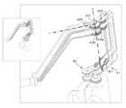
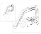
図11は、図7A及び図7Bに図示された本発明の一実施形態による手術用インスツルメント100のピッチ動作と係わるプーリー及びワイヤの構成を、第1ジョー及び第2ジョーそれぞれについて分けて図示した図面である。図11(a)は、第2ジョーと係わるプーリー及びワイヤのみを示した図面であり、図11(b)は、第1ジョーと係わるプーリー及びワイヤのみを示した図面である。図8に図示されているように、ピッチ動作と係わるプーリーは、それぞれ2個であり、各ワイヤの両筋が同じ経路に巻かれており、図11としては、それらを1本の線で表現した。そして、図12は、図7A及び図7Bの手術用インスツルメントのピッチ動作を示す斜視図である。 FIG. 11 shows the configurations of the pulley and the wire related to the pitch operation of the
図11(b)を参照すれば、第1取っ手114を、ピッチ回転軸1111を中心に、矢印OPP1方向に回転させれば、第1アクチュエーションプーリー113P1、第1ジョー・ピッチ補助プーリー111S1a、111S1b、第1ジョー・ピッチプーリー111P1a,111P1bと、それらに巻かれている第1ジョーワイヤ130J1とが全体的にピッチ回転軸1111を中心に回転する。このとき、図8のように、第1ジョーワイヤ130J1の両筋は、第1ジョー・ピッチプーリー111P1a,111P1bの上側に巻かれているために、矢印W1側に移動することになる。結果として、図5を通じて説明したように、エンドツール120の第1ジョー121が、矢印EPP1方向に回転することになる。 With reference to FIG. 11B, if the
図11(a)を参照すれば、第1取っ手114を、ピッチ回転軸1111を中心に、矢印OPP2方向に回転させれば、第2アクチュエーションプーリー113P2、第2ジョー・ピッチ補助プーリー111S2a、111S2b、第2ジョー・ピッチプーリー111P2a,111P2bと、それらに巻かれている第2ジョーワイヤ130J2とが、全体的にピッチ回転軸1111を中心に回転する。このとき、図8のように、第2ジョーワイヤ130J2の両筋は、第2ジョー・ピッチプーリー111P2a,111P2bの下側に巻かれているために、矢印W2側に移動することになる。結果として、図5を通じて説明したように、エンドツール120の第2ジョー122が、矢印EPP2方向に回転することになる。 With reference to FIG. 11A, if the
従って、第1実施形態を示す図7A及び図7Bは、図8、図9、図10、図11、図12を通じて、動作原理について説明することができ、アクチュエーション操作、ヨー操作、ピッチ操作は、互いに独立して操作が可能である。 Therefore, FIGS. 7A and 7B showing the first embodiment can explain the operating principle through FIGS. 8, 9, 10, 11, and 12, and the actuation operation, yaw operation, and pitch operation can be described. , Can be operated independently of each other.
図1を通じて説明したように、アクチュエーション操作部113、ヨー操作部112、ピッチ操作部111は、自体の回転軸が、各操作部の後方に位置することにより、エンドツールの関節構成と同一に構成され、ユーザが直観的に一致する操作を遂行することが可能である。 As described with reference to FIG. 1, the
特に、本発明の一実施形態による手術用インスツルメント100は、各関節地点(アクチュエーション関節、ヨー関節、ピッチ関節)にプーリーが形成され、該プーリーをワイヤ(第1ジョーワイヤまたは第2ジョーワイヤ)が巻くように形成されており、操作部の回転操作(アクチュエーション回転、ヨー回転、ピッチ回転)が、各ワイヤの移動を起こし、結果として、エンドツール120の所望動作を誘導することを特徴とする。さらに、各プーリーの一側には、補助プーリーが形成され、該補助プーリーにより、1つのプーリーにワイヤが何回も巻かれないようになり、プーリーに巻かれるワイヤが互いに接触せず、プーリーに巻かれて入っていくワイヤと、巻かれて出てくるワイヤの経路も安全に形成され、ワイヤの動力伝達の安全性及び効率などを向上させることができる。 In particular, in the
一方、前述のように、ヨー操作部112とアクチュエーション操作部113は、第1取っ手114上に直接形成されている。従って、第1取っ手114が、ピッチ回転軸1111を中心に回転すれば、ヨー操作部112及びアクチュエーション操作部113も、第1取っ手114と共に回転することになる。それにより、ヨー操作部112とアクチュエーション操作部113との座標系は、固定されているのではなく、第1取っ手114の回転により、相対的に続けて変化することになる。すなわち、図2などには、ヨー操作部112及びアクチュエーション操作部113は、Z軸と平行であるように図示されている。しかし、第1取っ手114が回転すれば、ヨー操作部112とアクチュエーション操作部113とがZ軸と平行ではなくなる。すなわち、ヨー操作部112とアクチュエーション操作部113との座標系が、第1取っ手114の回転によって変化したのである。ただし、本明細書においては、説明の便宜のために、別途の説明がない以上、ヨー操作部112とアクチュエーション操作部113との座標系は、図2のように、第1取っ手114が連結部140に対して垂直に位置した状態を基準にして説明した。 On the other hand, as described above, the
<関節の多様な変形例>
ヨー回転またはプーリー回転のために、主関節プーリーと追加的補助プーリーとによって構成された関節構造は、2つの構成によって、異なる変形例が可能であり、直接型関節及び間接型関節に分けられる。<Various joint deformation examples>
The joint structure composed of the main joint pulley and the additional auxiliary pulley for yaw rotation or pulley rotation can be differently modified by the two configurations and can be divided into direct type joint and indirect type joint.
(直接型関節及び間接型関節−ヨー関節)
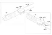
図13は、ヨー関節の直接型関節の一例を示す図面であり、図14は、ヨー関節の間接型関節の一例を示す図面である。図13(a)及び図14(a)は、第2ジョーと係わるプーリー及びワイヤのみを示した図面であり、図13(b)及び図14(b)は、第1ジョーと係わるプーリー及びワイヤのみを示した図面である。(Direct and indirect joints-yaw joints)
FIG. 13 is a drawing showing an example of a direct type joint of a yaw joint, and FIG. 14 is a drawing showing an example of an indirect type joint of a yaw joint. 13 (a) and 14 (a) are drawings showing only the pulley and the wire related to the second jaw, and FIGS. 13 (b) and 14 (b) are the pulley and the wire related to the first jaw. It is a drawing which showed only.
ここで、直接型関節とは、1つの関節運動のために、互いに隣接した2つのプーリーを具備する構成において、関節位置に該当するプーリーと補助プーリーとの関係において、当該関節部の回転軸に対して当該関節部が回転するとき、補助プーリーは、当該関節部の回転軸を基準に回転せず、関節位置に該当するプーリーだけ当該関節部の回転軸を基準に回転する場合を意味する。一方、間接型関節とは、当該関節部の回転軸に対して当該関節部が回転するとき、関節位置に該当するプーリーだけではなく、補助プーリーも、当該関節部の回転軸を基準に回転する場合を意味する。 Here, the direct type joint is a configuration in which two pulleys adjacent to each other are provided for one joint movement, and in the relationship between the pulley corresponding to the joint position and the auxiliary pulley, the rotation axis of the joint portion is used. On the other hand, when the joint portion rotates, the auxiliary pulley does not rotate with reference to the rotation axis of the joint portion, but only the pulley corresponding to the joint position rotates with reference to the rotation axis of the joint portion. On the other hand, in the indirect joint, when the joint rotates with respect to the rotation axis of the joint, not only the pulley corresponding to the joint position but also the auxiliary pulley rotates with reference to the rotation axis of the joint. Means the case.
一方、直接型関節を図示した図13は、第1ジョー121のヨー運動のために、互いに隣接するように形成された第1ジョー・ヨープーリー112P1と第1ジョー・ヨー補助プーリー112S1とを具備し、ヨー回転軸1121上に位置し、ヨー回転時、ヨー回転軸1121を中心に回転する、図面上左側に位置するプーリーが、第1ジョー・ヨープーリー112P1になる。このとき、第1ジョー・ヨー補助プーリー112S1は、図面上右側に位置し、ヨー回転時、ヨー回転軸1121を中心に回転しない。 On the other hand, FIG. 13 showing the direct type joint includes a first jaw yaw pulley 112P1 and a first jaw yaw auxiliary pulley 112S1 formed so as to be adjacent to each other for the yaw movement of the
一方、間接型関節を図示した図14は、第1ジョー121のヨー運動のために、互いに隣接するように形成された第1ジョー・ヨープーリー112P1と第1ジョー・ヨー補助プーリー112S1とを具備し、ヨー回転軸1121上に位置し、ヨー回転時、ヨー回転軸1121を中心に回転する、図面上右側に位置するプーリーが、第1ジョー・ヨープーリー112P1になる。このとき、第1ジョー・ヨー補助プーリー112S1は、図面上左側に位置し、ヨー回転時、ヨー回転軸1121を中心に回転する。 On the other hand, FIG. 14 showing the indirect joint includes a first jaw yaw pulley 112P1 and a first jaw yaw auxiliary pulley 112S1 formed so as to be adjacent to each other for the yaw movement of the
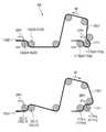
かような直接型関節及び間接型関節は、関節を同一方向に回転したとき、ワイヤの移動方向において差異がある。すなわち、直接型関節を図示した図13において、ヨー回転軸1121をOPY方向に回転させれば、第1ジョーワイヤ130J1及び第2ジョーワイヤ130J2の一側は、矢印D1方向に移動する一方、間接型関節を図示した図14において、ヨー回転軸1121をOPY方向に回転させれば、第1ジョーワイヤ130J1及び第2ジョーワイヤ130J2の一側は、D1と反対方向である矢印D2方向に移動することになる。 Such direct joints and indirect joints differ in the direction of wire movement when the joints are rotated in the same direction. That is, in FIG. 13 in which the direct type joint is illustrated, if the
このように、直接型関節及び間接型関節のうちいずれの方式によって関節構造を構成するかということにより、同一方向のヨー回転に対して、ワイヤの移動方向を互いに反対に構成することができる効果を得ることができる。 In this way, depending on which method of the direct type joint and the indirect type joint is used to form the joint structure, the effect that the moving directions of the wires can be formed opposite to each other with respect to the yaw rotation in the same direction. Can be obtained.
(直接型関節及び間接型関節−ピッチ関節)
図15は、ピッチ関節の間接型関節の一例を示す図面であり、図16は、ピッチ関節の直接型関節の一例を示す図面である。図15(a)及び図16(a)は、第2ジョーと係わるプーリー及びワイヤのみを示した図面であり、図15(b)及び図16(b)は、第1ジョーと係わるプーリー及びワイヤのみを示した図面である。(Direct and indirect joints-pitch joints)
FIG. 15 is a drawing showing an example of an indirect type joint of a pitch joint, and FIG. 16 is a drawing showing an example of a direct type joint of a pitch joint. 15 (a) and 16 (a) are drawings showing only the pulley and the wire related to the second jaw, and FIGS. 15 (b) and 16 (b) are the pulley and the wire related to the first jaw. It is a drawing which showed only.
間接型関節を図示した図15(b)は、第1ジョー121のピッチ運動のために、互いに隣接するように形成された第1ジョー・ピッチプーリーa 111P1aと第1ジョー・ピッチ補助プーリーa 111S1aとを具備し、このとき、図面上右側に位置したプーリーが、第1ジョー・ピッチプーリーa 111P1aになる。 FIG. 15B, which illustrates the indirect joint, shows the first jaw pitch pulley a 111P1a and the first jaw pitch auxiliary pulley a 111S1a formed so as to be adjacent to each other for the pitch movement of the
直接型関節を図示した図16(b)は、第1ジョー121のピッチ運動のために、互いに隣接するように形成された第1ジョー・ピッチプーリーa 111P1aと第1ジョー・ピッチ補助プーリーa 111S1aとを具備し、このとき、図面上左側に位置したプーリーが、第1ジョー・ピッチプーリーa 111P1aになる。 FIG. 16B, which illustrates the direct joint, shows the first jaw pitch pulley a 111P1a and the first jaw pitch auxiliary pulley a 111S1a formed so as to be adjacent to each other for the pitch movement of the
このように、直接型関節及び間接型関節のうちいずれの方式によって関節構造を構成するかということにより、同一方向のピッチ回転に対して、ワイヤの移動方向を互いに反対に構成することができる効果を得ることができ、それを介して、ピッチプーリーにワイヤが巻かれる方向を異ならせることもできる。 In this way, depending on which method of the direct type joint and the indirect type joint is used to form the joint structure, the effect that the moving directions of the wires can be formed opposite to each other with respect to the pitch rotation in the same direction. Can be obtained, through which the wire can be wound in different directions on the pitch pulley.
(プーリー及びワイヤ構成の多様な変形例)
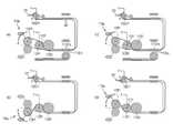
図9に図示された本発明の第1実施形態による手術用インスツルメント100のアクチュエーション動作及びヨー動作と係わるプーリー及びワイヤ構成は、ワイヤの経路、関節プーリーの大きさ及び配置、操作部、並びにエンドツール構成などの変形を介した多様な変形例を有することができる。以下では、想定することができるプーリー及びワイヤ構成の多様な変形例について説明する。(Various modifications of pulley and wire configuration)
The pulley and wire configurations related to the actuation operation and yaw operation of the
図17は、図9に図示された本発明の一実施形態による手術用インスツルメント100の第1ジョー121の動作と係わるプーリー及びワイヤの構成、並びにその変形例を図示した図面である。 FIG. 17 is a drawing illustrating a configuration of a pulley and a wire related to the operation of the
図17(a)を参照すれば、図17(a)に図示された本発明の一実施形態による手術用インスツルメント100は、基本的には、連結部140内でワイヤが交差しない。すなわち、エンドツール120と操作部110とを連結する連結部140内において、第1ジョーワイヤ130J1の両筋は、互いに交差していない状態に形成され、第2ジョーワイヤ130J2も、その両筋は、互いに交差していない状態に形成される。 Referring to FIG. 17 (a), in the
一方、図17(a)に図示された本発明の一実施形態による手術用インスツルメント100は、連結部140内において、各ワイヤが広がっていくように形成される。すなわち、仲介プーリーの大きさ及び間隔によって、エンドツール120での第1ジョーワイヤ130J1の両筋間の間隔は、仲介プーリーMPで連結されて形成される両筋間の間隔より狭く形成されるために、エンドツール120において、仲介プーリー側に行くほど、第1ジョーワイヤ130J1の両筋間の間隔がだんだん遠くなり、全体的に、第1ジョーワイヤ130J1が広がっていくように形成されるのである。 On the other hand, the
一方、図17(a)に図示された本発明の一実施形態による手術用インスツルメント100は、操作部110のヨー関節が直接型に形成される。すなわち、手術用インスツルメント100は、第1ジョー121のヨー運動のために、互いに隣接するように形成された第1ジョー・ヨープーリー112P1と第1ジョー・ヨー補助プーリー112S1とを具備し、このとき、図面上左側に位置したプーリーが、第1ジョー・ヨープーリー112P1になり、第1ジョー・ヨープーリー112P1の回転軸がヨー回転軸になる。このとき、第1ジョー・ヨー補助プーリー112S1は、互いに対向するように形成され、独立して回転自在に形成される2つのプーリーによって形成され、このとき、2つのプーリーは、互いに異なる直径を有するようにも形成される。このとき、第1ジョー・ヨープーリー112P1と第1ジョー・ヨー補助プーリー112S1とを交差して巻かれるワイヤが、経路上互いに重ならないように、第1ジョー・ヨープーリー112P1及び第1ジョー・ヨー補助プーリー112S1それぞれは、2つのプーリーを具備し、第1ジョーワイヤ130J1の両筋が高さ差を有するようにする。そして、そのために、ピッチ補助プーリーも、互いに異なる直径を有する2つのプーリー(第1ジョー・ピッチ補助プーリーa 111S1a及び第1ジョー・ピッチ補助プーリーb 111S1b)を有するようにし、高さ差が出るプーリーに、自然に第1ジョーワイヤ130J1が巻かれるように構成する。 On the other hand, in the
図17(b)の場合、第1ジョー・ヨー補助プーリー112S1と連結されるピッチ補助プーリー(第1ジョー・ピッチ補助プーリーa 111S1a及び第1ジョー・ピッチ補助プーリーb 111S1b)の大きさ及び配置を、図17(a)の場合と異ならせることにより、図17(b)の下側図面のように、第1ジョー・ピッチ補助プーリーa 111S1aに巻かれるワイヤと、第1ジョー・ピッチ補助プーリーb 111S1bに巻かれるワイヤとの高さが反対になるように配置することができ、結果として、図17(a)に比べ、第1ジョーワイヤ130J1の両筋上下関係が反対になるように構成することができる。 In the case of FIG. 17B, the size and arrangement of the pitch auxiliary pulleys (first jaw pitch auxiliary pulley a 111S1a and first jaw pitch auxiliary pulley b 111S1b) connected to the first jaw / yaw auxiliary pulley 112S1 are arranged. By making it different from the case of FIG. 17A, as shown in the lower drawing of FIG. 17B, the wire wound around the first jaw pitch auxiliary pulley a 111S1a and the first jaw pitch auxiliary pulley b. It can be arranged so that the height of the wire wound around 111S1b is opposite to that of the wire, and as a result, the vertical relationship between the first jaw wire 130J1 is opposite to that of FIG. 17A. be able to.
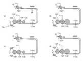
図17(c)の場合、第1ジョーの駆動のための第1アクチュエーション操作部113aを、図17(a)の場合と異ならせた構成であり、操作部110でのアクチュエーション動作と、ヨー動作によるエンドツール120の動作とが、図17(a)と同一に遂行されるようにするために、第1ジョー・ヨープーリー112P1と第1アクチュエーションプーリー113P1とを連結する第1ジョーワイヤ130J1が互いに交差されるように構成することができる。 In the case of FIG. 17 (c), the first
図17(d)の場合、第1ジョー121及びJ11プーリー123J11の構成を異ならせた場合であり、図17(a)と異なる方向に、第1ジョー121が形成されるようにした場合であり、このとき、ヨー動作のための第1ジョー121の回転方向は、図17(a)と同一であるが、アクチュエーション動作のための第1ジョー121及びJ11プーリー123J11の回転方向は、図17(a)と反対になる。そのために、第1アクチュエーション操作部113aの動作が、図17(a)と反対に、第1ジョーワイヤ130J1を移動させるために、第1ジョー・ヨープーリー112P1と第1アクチュエーションプーリー113P1とを連結する第1ジョーワイヤ130J1が互いに交差されるように構成することができる。 In the case of FIG. 17D, the configurations of the
本構成においては、2個のヨープーリー、2個のヨー補助プーリー、2個のピッチプーリー、2個のピッチ補助プーリーが形成され、図面上に交差されるように見えるワイヤは、実際には、他の経路上に位置して物理的に接触せず、それを介して、ワイヤによる動力伝達の安全性及び効率などを向上させることができる。 In this configuration, two yaw pulleys, two yaw auxiliary pulleys, two pitch pulleys, and two pitch auxiliary pulleys are formed, and the wires that appear to intersect in the drawing are actually other. It is located on the path of the wire and does not make physical contact, through which the safety and efficiency of power transmission by the wire can be improved.
前述のところは、第1ジョーのアクチュエーション動作、ヨー動作に係わるものであり、図面も、第1ジョーのアクチュエーション動作、ヨー動作の説明のためのものであり、仲介プーリー及びピッチ動作に係わるプーリーに係わる説明がなくとも、十分に理解が可能であるが、本図面においては、仲介プーリー及びピッチ動作に係わるプーリーは、省略されている。それだけではなく、第2ジョーの場合も、第1ジョーに係わる図面及び説明を介して十分に理解されるが、第2ジョーに係わる図面及び説明は省略する。 The above is related to the actuation operation and yaw operation of the first jaw, and the drawings are also for explaining the actuation operation and yaw operation of the first jaw, and are related to the mediation pulley and the pitch operation. Although it is possible to fully understand the pulley without explanation, the mediation pulley and the pulley related to the pitch operation are omitted in this drawing. Not only that, the second jaw is also fully understood through the drawings and description relating to the first jaw, but the drawings and description relating to the second jaw will be omitted.
図18は、図17に開示された実施形態の他の一変形例を示す図面であり、図17において、ワイヤ経路などを変形させた変形例である。 FIG. 18 is a drawing showing another modified example of the embodiment disclosed in FIG. 17, and is a modified example in which a wire path or the like is deformed in FIG.
図18(a)の場合、第1実施形態による構成と異なり、第1ジョー121を巻くように構成された第1ジョーワイヤ130J1の両筋が、互いに隣接した2つの連結部仲介プーリーMPを通過するするように構成された変形例であり、第1実施形態による構成と同一動作が可能になるように、第1ジョー・ヨー補助プーリー112S1などの構成が変形された例である。 In the case of FIG. 18A, unlike the configuration according to the first embodiment, both bars of the first jaw wire 130J1 configured to wind the
そのために、第1ジョーワイヤ130J1が通過するする互いに異なる大きさのピッチ補助プーリー(第1ジョー・ピッチ補助プーリーa 111S1a及び第1ジョー・ピッチ補助プーリーb 111S1b)が互いに隣接するように並んで形成され、第1ジョー・ピッチ補助プーリーa 111S1aを通過した第1ジョーワイヤ130J1は、第1ジョー・ヨー補助プーリー112S1に巻かれるように構成し、第1ジョー・ピッチ補助プーリーb 111S1bを通過するする第1ジョーワイヤ130J1は、ヨー補助プーリーに巻かれずに、すぐに第1ジョー・ヨープーリー112P1に巻かれるように形成され、それを介して、図18(a)で説明する変形例は、第1実施形態と同一動作が可能になる。図18(a)による構成は、ワイヤの経路、関節プーリーの大きさ及び配置、操作部、並びにエンドツール構成などの変形を介した多様な変形例を有することができる。 Therefore, pitch auxiliary pulleys of different sizes (first jaw pitch auxiliary pulley a 111S1a and first jaw pitch auxiliary pulley b 111S1b) through which the first jaw wire 130J1 passes are formed side by side so as to be adjacent to each other. The first jaw wire 130J1 that has passed through the first jaw pitch auxiliary pulley a 111S1a is configured to be wound around the first jaw yaw auxiliary pulley 112S1 and passes through the first jaw pitch auxiliary pulley b 111S1b. The first jaw wire 130J1 is formed so as to be immediately wound around the first jaw yaw pulley 112P1 without being wound around the yaw auxiliary pulley. The same operation as in one embodiment becomes possible. The configuration according to FIG. 18 (a) can have various deformation examples through deformations such as a wire path, a size and arrangement of joint pulleys, an operation unit, and an end tool configuration.
図18(b)の場合、ヨー補助プーリーと連結されるピッチ補助プーリーの大きさを図18(a)の場合と異ならせることにより、図18(b)の下側図面のように、第1ジョー・ピッチ補助プーリーa 111S1aに巻かれるワイヤと、第1ジョー・ピッチ補助プーリーb 111S1bに巻かれるワイヤとの高さが反対になるように配置することができ、結果として、図18(a)に比べ、第1ジョーワイヤ130J1の両筋関係が反対になるように構成することができる。図18(c)の場合、第1ジョーの駆動のためのアクチュエーション操作部113aを、図18(a)の場合と異ならせた構成であり、操作部110でのアクチュエーション動作及びヨー動作によるエンドツール120の動作が、図18(a)と同一に遂行されるようにするために、第1ジョー・ヨープーリー112P1と第1アクチュエーションプーリー113P1とを連結する第1ジョーワイヤ130J1が互いに交差されるように構成することができる。 In the case of FIG. 18 (b), by making the size of the pitch auxiliary pulley connected to the yaw auxiliary pulley different from that in the case of FIG. 18 (a), as shown in the lower drawing of FIG. 18 (b), the first The wire wound around the jaw pitch auxiliary pulley a 111S1a and the wire wound around the first jaw pitch auxiliary pulley b 111S1b can be arranged so as to be opposite in height, and as a result, FIG. 18 (a) shows. The first jaw wire 130J1 can be configured so that the relationship between the two muscles is opposite to that of the first jaw wire 130J1. In the case of FIG. 18C, the
図18(d)の場合、第1ジョー121及びJ11プーリー123J11の構成を異ならせた場合であり、図18(a)と異なる方向に、第1ジョー121が形成されるようにした場合であり、このとき、ヨー動作のための第1ジョー121の回転方向は、図18(a)と同一であるが、アクチュエーション動作のための第1ジョー121及びJ11プーリー123J11の回転方向は、図18(a)と反対になる。そのために、第1アクチュエーション操作部113aの動作が、図18(a)と反対に、第1ジョーワイヤ130J1を移動させるために、第1ジョー・ヨープーリー112P1と第1アクチュエーションプーリー113P1とを連結する第1ジョーワイヤ130J1が互いに交差されるように構成することができる。 In the case of FIG. 18D, the configurations of the
本構成においては、2個のヨープーリー、1個のヨー補助プーリー、2個のピッチプーリー、2個のピッチ補助プーリーが形成され、図面上に交差されるように見えるワイヤは、実際には、他の経路上に位置して物理的に接触せず、それを介して、ワイヤによる動力伝達の安全性及び効率などを向上させることができる。 In this configuration, two yaw pulleys, one yaw auxiliary pulley, two pitch pulleys, and two pitch auxiliary pulleys are formed, and the wires that appear to intersect in the drawing are actually other. It is located on the path of the wire and does not make physical contact, through which the safety and efficiency of power transmission by the wire can be improved.
前述のところは、第1ジョーのアクチュエーション動作、ヨー動作に係わるものであり、図面も、第1ジョーのアクチュエーション動作、ヨー動作の説明のためのものであり、仲介プーリー及びピッチ動作に係わるプーリーに係わる説明がなくとも、十分に理解が可能であるが、本図面においては、仲介プーリー及びピッチ動作に係わるプーリーは、省略されている。それだけではなく、第2ジョーの場合も、第1ジョーに係わる図面及び説明を介して十分に理解されるが、第2ジョーに係わる図面及び説明は省略する。 The above is related to the actuation operation and yaw operation of the first jaw, and the drawings are also for explaining the actuation operation and yaw operation of the first jaw, and are related to the mediation pulley and the pitch operation. Although it is possible to fully understand the pulley without explanation, the mediation pulley and the pulley related to the pitch operation are omitted in this drawing. Not only that, the second jaw is also fully understood through the drawings and description relating to the first jaw, but the drawings and description relating to the second jaw will be omitted.
図19は、図17に開示された実施形態の他の一変形例を示す図面であり、図17において、ワイヤ経路などを変形させた変形例である。 FIG. 19 is a drawing showing another modified example of the embodiment disclosed in FIG. 17, and is a modified example in which a wire path or the like is deformed in FIG.
図19(a)の場合、第1実施形態による構成と異なり、第1ジョー121を巻くように構成された第1ジョーワイヤ130J1の両筋が互いに交差し、互いに隣接した2つの連結部仲介プーリーMPを通過するするように構成された変形例であり、第1実施形態による構成と同一動作が可能になるように、第1ジョー・ヨー補助プーリー112S1などの構成が変形された例である。 In the case of FIG. 19A, unlike the configuration according to the first embodiment, both bars of the first jaw wire 130J1 configured to wind the
また、図19(a)の場合、第1実施形態による構成と異なり、連結部140内において、ワイヤが少なくとも1回交差される。すなわち、エンドツール120と操作部110とを連結する連結部140内において、第1ジョーワイヤ130J1の両筋は、互いに交差するように形成され、第2ジョーワイヤ130J2も、その両筋が互いに交差するように形成される。ただし、図面上の二次元平面で見たときは、各ワイヤの両筋が互いに交差するように見えるが、実際ワイヤが連結される仲介プーリーの三次元上の適切な位置構成を介して、実際には、ワイヤが物理的に接触しないように容易に構成することができる。 Further, in the case of FIG. 19A, unlike the configuration according to the first embodiment, the wires are crossed at least once in the connecting
一方、第1ジョー・ピッチ補助プーリーa 111S1a及び第1ジョー・ピッチ補助プーリーb 111S1bは、同一径を有するように形成され、第1ジョー・ピッチ補助プーリーb 111S1bに巻かれた第1ジョーワイヤ130J1は、第1ジョー・ヨー補助プーリー112S1を経て、第1ジョー・ヨープーリー112P1に巻かれるようになっている。一方、第1ジョー・ピッチ補助プーリーa 111S1aに巻かれた第1ジョーワイヤ130J1の場合、ヨー補助プーリーなしにすぐに第1ジョー・ヨープーリー112P1に巻かれるように形成され、それを介して、図19(a)で説明する変形例は、第1実施形態と同一動作が可能である。 On the other hand, the first jaw pitch auxiliary pulley a 111S1a and the first jaw pitch auxiliary pulley b 111S1b are formed so as to have the same diameter, and the first jaw wire 130J1 wound around the first jaw pitch auxiliary pulley b 111S1b. Is wound around the first jaw yaw pulley 112P1 via the first jaw yaw auxiliary pulley 112S1. On the other hand, in the case of the first jaw wire 130J1 wound around the first jaw pitch auxiliary pulley a 111S1a, the first jaw wire 130J1 is formed so as to be immediately wound around the first jaw yaw pulley 112P1 without the yaw auxiliary pulley. The modification described in 19 (a) can perform the same operation as that of the first embodiment.
図19(a)による構成は、ワイヤの経路、関節プーリーの大きさ及び配置、操作部、並びにエンドツール構成などの変形を介した多様な変形例を有することができる。 The configuration according to FIG. 19 (a) can have various deformation examples through deformations such as a wire path, a size and arrangement of joint pulleys, an operation unit, and an end tool configuration.
図19(b)の場合、ヨー補助プーリーと連結されるピッチ補助プーリーの大きさを、図19(a)の場合と異ならせ、第1ジョー・ピッチ補助プーリーa 111S1aと、第1ジョー・ピッチ補助プーリーb 111S1bとの直径を異なるように形成することにより、図19(b)の下側図面のように、第1ジョー・ヨープーリー112P1の2つのプーリーが互いに異なる高さに位置するようにする。それは、後述する図19(c)のように、第1アクチュエーションプーリー113P1と第1ジョー・ヨープーリー112P1との間で、第1ジョーワイヤ130J1が交差される構成に適用が容易であり、第1ジョーワイヤ130J1の両側が、実際には物理的な接触がないようにする。 In the case of FIG. 19B, the size of the pitch auxiliary pulley connected to the yaw auxiliary pulley is different from that in the case of FIG. 19A, and the first jaw pitch auxiliary pulley a 111S1a and the first jaw pitch are different. By forming the auxiliary pulley b 111S1b so as to have a different diameter, the two pulleys of the first jaw yaw pulley 112P1 are located at different heights as shown in the lower drawing of FIG. 19B. .. It is easy to apply to a configuration in which the first jaw wire 130J1 intersects between the first actuation pulley 113P1 and the first jaw yaw pulley 112P1 as shown in FIG. 19C described later, and the first Make sure that both sides of the jawwire 130J1 are not actually in physical contact.
図19(c)の場合、第1ジョーの駆動のためのアクチュエーション操作部113aを、図19(a)の場合と異ならせた構成であり、操作部110でのアクチュエーション動作及びヨー動作によるエンドツール120の動作が、図19(a)と同一に遂行されるようにするために、第1ジョー・ヨープーリー112P1と第1アクチュエーションプーリー113P1とを連結する第1ジョーワイヤ130J1が互いに交差されるように構成することができる。 In the case of FIG. 19 (c), the
図19(d)の場合、第1ジョー121及びJ11プーリー123J11の構成を異ならせた場合であり、図19(a)と異なる方向に、第1ジョー121が形成されるようにした場合であり、このとき、ヨー動作のための第1ジョー121の回転方向は、図19(a)と同一であるが、アクチュエーション動作のための第1ジョー121及びJ11プーリー123J11の回転方向は、図19(a)と反対になる。そのために、第1アクチュエーション操作部113aの動作が、図19(a)と反対に、第1ジョーワイヤ130J1を移動させるために、第1ジョー・ヨープーリー112P1と第1アクチュエーションプーリー113P1とを連結する第1ジョーワイヤ130J1が互いに交差されるように構成することができる。 In the case of FIG. 19D, the configurations of the
本構成においては、1個または2個のヨープーリー、1個のヨー補助プーリー、2個のピッチプーリー、2個のピッチ補助プーリーが形成され、図面上に交差されるように見えるワイヤは、実際には、他の経路上に位置して物理的に接触せず、それを介して、ワイヤによる動力伝達の安全性及び効率などを向上させることができる。 In this configuration, one or two yaw pulleys, one yaw auxiliary pulley, two pitch auxiliary pulleys, and two pitch auxiliary pulleys are formed, and the wires that appear to intersect on the drawing are actually Is located on another path and does not physically contact, through which the safety and efficiency of power transmission by the wire can be improved.
それだけではなく、図面上に表示されたピッチ補助プーリーの代わりに、ピッチプーリーを配置する構成も可能である。 Not only that, it is also possible to arrange a pitch pulley instead of the pitch auxiliary pulley displayed on the drawing.
前述のところは、第1ジョーのアクチュエーション動作、ヨー動作に係わるものであり、図面も、第1ジョーのアクチュエーション動作、ヨー動作の説明のためのものであり、仲介プーリー及びピッチ動作に係わるプーリーに係わる説明がなくとも、十分に理解が可能であるが、本図面においては、仲介プーリー及びピッチ動作に係わるプーリーは、省略されている。それだけではなく、第2ジョーの場合も、第1ジョーに係わる図面及び説明を介して十分に理解されるが、第2ジョーに係わる図面及び説明は省略する。 The above is related to the actuation operation and yaw operation of the first jaw, and the drawings are also for explaining the actuation operation and yaw operation of the first jaw, and are related to the mediation pulley and the pitch operation. Although it is possible to fully understand the pulley without explanation, the mediation pulley and the pulley related to the pitch operation are omitted in this drawing. Not only that, the second jaw is also fully understood through the drawings and description relating to the first jaw, but the drawings and description relating to the second jaw will be omitted.
図20は、図17に開示された実施形態の他の一変形例を示す図面であり、図17において、ワイヤ経路などを変形させた変形例である。 FIG. 20 is a drawing showing another modified example of the embodiment disclosed in FIG. 17, and is a modified example in which a wire path or the like is deformed in FIG.
図20(a)の場合、第1実施形態による構成と異なり、第1ジョー121を巻くように構成された第1ジョーワイヤ130J1の両筋が互いに交差し、互いに隣接しない2つの連結部仲介プーリーMPを通過するするように構成された変形例であり、第1実施形態による構成と同一動作が可能になるように、第1ジョー・ヨー補助プーリー112S1などの構成が変形された例である。
また、図20(a)の場合、第1実施形態による構成と異なり、連結部140内において、ワイヤが少なくとも1回交差される。すなわち、エンドツール120と操作部110とを連結する連結部140内において、第1ジョーワイヤ130J1の両筋は、互いに交差するように形成され、第2ジョーワイヤ130J2も、その両筋が互いに交差するように形成される。ただし、図面上の二次元平面で見たときは、各ワイヤの両筋が互いに交差するように見えるが、実際ワイヤが連結される仲介プーリーの三次元上の適切な構成を介して、実際には、ワイヤが物理的に接触しないように容易に構成することができる。In the case of FIG. 20A, unlike the configuration according to the first embodiment, both bars of the first jaw wire 130J1 configured to wind the
Further, in the case of FIG. 20A, unlike the configuration according to the first embodiment, the wires are crossed at least once in the connecting
また、互いに異なる大きさのピッチ補助プーリー(第1ジョー・ピッチ補助プーリーa 111S1a及び第1ジョー・ピッチ補助プーリーb 111S1b)が形成され、外側ピッチ補助プーリーである第1ジョー・ピッチ補助プーリーa 111S1aがさらに大きく構成され、外側ピッチ補助プーリーに巻かれるワイヤがさらに低い方に位置する第1ジョー・ヨー補助プーリー112S1に巻かれるように構成した。 Further, pitch auxiliary pulleys having different sizes (first jaw pitch auxiliary pulley a 111S1a and first jaw pitch auxiliary pulley b 111S1b) are formed, and the first jaw pitch auxiliary pulley a 111S1a which is an outer pitch auxiliary pulley is formed. Is configured to be larger so that the wire wound around the outer pitch auxiliary pulley is wound around the first jaw yaw auxiliary pulley 112S1 located at a lower position.
一方、図20(a)に図示された本発明の一実施形態による手術用インスツルメント100は、操作部110のヨー関節が間接型に形成される。すなわち、手術用インスツルメント100は、第1ジョー121のヨー運動のために、互いに隣接するように形成された第1ジョー・ヨープーリー112P1と第1ジョー・ヨー補助プーリー112S1とを具備し、このとき、図面上右側に位置したプーリーが第1ジョー・ヨープーリー112P1になり、第1ジョー・ヨープーリー112P1の回転軸がヨー回転軸になる。その場合、操作部110でのアクチュエーション動作及びヨー動作によるエンドツールの動作が、図17(a)と同一に遂行されるようにするために、第1ジョー・ヨー補助プーリー112S1と第1アクチュエーションプーリー113P1とを連結する第1ジョーワイヤ130J1が互いに交差されるように構成することができる。 On the other hand, in the
図20(a)による構成は、ワイヤの経路、関節プーリーの大きさ及び配置、操作部、並びにエンドツール構成などの変形を介した多様な変形例を有することができる。 The configuration according to FIG. 20 (a) can have various deformation examples through deformations such as a wire path, a size and arrangement of joint pulleys, an operation unit, and an end tool configuration.
図20(b)の場合、第1ジョー・ヨー補助プーリー112S1と連結されるピッチ補助プーリー(第1ジョー・ピッチ補助プーリーa 111S1a及び第1ジョー・ピッチ補助プーリーb 111S1b)の大きさ及び配置を、図20(a)の場合と異ならせることにより、第1ジョー・ピッチ補助プーリーa 111S1aに巻かれるワイヤと、第1ジョー・ピッチ補助プーリーb 111S1bに巻かれるワイヤとの高さが反対になるように配置することができ、結果として、図20(a)に比べ、第1ジョーワイヤ130J1の両筋上下関係が反対になるように構成することができる。 In the case of FIG. 20B, the size and arrangement of the pitch auxiliary pulleys (first jaw pitch auxiliary pulley a 111S1a and first jaw pitch auxiliary pulley b 111S1b) connected to the first jaw / yaw auxiliary pulley 112S1 are arranged. By making the wire different from the case of FIG. 20A, the heights of the wire wound around the first jaw pitch auxiliary pulley a 111S1a and the wire wound around the first jaw pitch auxiliary pulley b 111S1b are opposite to each other. As a result, it is possible to configure the first jaw wire 130J1 so that the vertical relationship between the two streaks is opposite to that of FIG. 20A.
図20(c)の場合、第1ジョーの駆動のためのアクチュエーション操作部113aを、図20(a)の場合と異ならせた構成であり、操作部110でのアクチュエーション動作及びヨー動作によるエンドツール120の動作が、図20(a)と同一に遂行されるようにするために、第1ジョー・ヨー補助プーリー112S1と第1アクチュエーションプーリー113P1とを連結する第1ジョーワイヤ130J1が互いに交差されないように構成することができる。 In the case of FIG. 20 (c), the
図20(d)の場合、第1ジョー121及びJ11プーリー123J11の構成を異ならせた場合であり、図20(a)と異なる方向に、第1ジョー121が形成されるようにした場合であり、このとき、ヨー動作のための第1ジョー121の回転方向は、図20(a)と同一であるが、アクチュエーション動作のための第1ジョー121及びJ11プーリー123J11の回転方向は、図20(a)と反対になる。そのために、第1アクチュエーション操作部113aの動作が、図20(a)と反対に、第1ジョーワイヤ130J1を移動させるために、第1ジョー・ヨー補助プーリー112S1と第1アクチュエーションプーリー113P1とを連結する第1ジョーワイヤ130J1が互いに交差されないように構成することができる。 In the case of FIG. 20 (d), the configurations of the
本構成においては、2個のヨープーリー、2個のヨー補助プーリー、2個のピッチプーリー、2個のピッチ補助プーリーが形成され、図面上に交差されるように見えるワイヤは、実際には、他の経路上に位置して物理的に接触せず、それを介して、ワイヤによる動力伝達の安全性及び効率などを向上させることができる。 In this configuration, two yaw pulleys, two yaw auxiliary pulleys, two pitch pulleys, and two pitch auxiliary pulleys are formed, and the wires that appear to intersect in the drawing are actually other. It is located on the path of the wire and does not make physical contact, through which the safety and efficiency of power transmission by the wire can be improved.
前述のところは、第1ジョーのアクチュエーション動作、ヨー動作に係わるものであり、図面も、第1ジョーのアクチュエーション動作、ヨー動作の説明のためのものであり、仲介プーリー及びピッチ動作に係わるプーリーに係わる説明がなくとも、十分に理解が可能であるが、本図面においては、仲介プーリー及びピッチ動作に係わるプーリーは、省略されている。それだけではなく、第2ジョーの場合も、第1ジョーに係わる図面及び説明を介して十分に理解されるが、第2ジョーに係わる図面及び説明は省略する。 The above is related to the actuation operation and yaw operation of the first jaw, and the drawings are also for explaining the actuation operation and yaw operation of the first jaw, and are related to the mediation pulley and the pitch operation. Although it is possible to fully understand the pulley without explanation, the mediation pulley and the pulley related to the pitch operation are omitted in this drawing. Not only that, the second jaw is also fully understood through the drawings and description relating to the first jaw, but the drawings and description relating to the second jaw will be omitted.
図21は、図17に開示された実施形態の他の一変形例を示す図面であり、図17において、ワイヤ経路などを変形させた変形例である。 FIG. 21 is a drawing showing another modified example of the embodiment disclosed in FIG. 17, and is a modified example in which a wire path or the like is deformed in FIG.
図21(a)の場合、第1実施形態による構成と異なり、第1ジョー121を巻くように構成された第1ジョーワイヤ130J1の両筋が互いに交差し、互いに隣接した2つの連結部仲介プーリーMPを通過するするように構成された変形例であり、第2ジョーワイヤ130J2も、その両筋が互いに交差するように形成される。 In the case of FIG. 21A, unlike the configuration according to the first embodiment, both bars of the first jaw wire 130J1 configured to wind the
一方、第1ジョー・ピッチ補助プーリーa 111S1a及び第1ジョー・ピッチ補助プーリーb 111S1bは、同一径を有するように形成され、第1ジョー・ピッチ補助プーリーb 111S1bに巻かれた第1ジョーワイヤ130J1は、第1ジョー・ヨー補助プーリー112S1を経て、第1ジョー・ヨープーリー112P1に巻かれるようになっている。一方、第1ジョー・ピッチ補助プーリーa 111S1aに巻かれた第1ジョーワイヤ130J1の場合、ヨー補助プーリーなしにすぐに第1ジョー・ヨープーリー112P1に巻かれるように形成され、それを介して、図21(a)で説明する変形例は、第1実施形態と同一動作が可能である。 On the other hand, the first jaw pitch auxiliary pulley a 111S1a and the first jaw pitch auxiliary pulley b 111S1b are formed so as to have the same diameter, and the first jaw wire 130J1 wound around the first jaw pitch auxiliary pulley b 111S1b. Is wound around the first jaw yaw pulley 112P1 via the first jaw yaw auxiliary pulley 112S1. On the other hand, in the case of the first jaw wire 130J1 wound around the first jaw pitch auxiliary pulley a 111S1a, the first jaw wire 130J1 is formed so as to be immediately wound around the first jaw yaw pulley 112P1 without the yaw auxiliary pulley. The modification described in 21 (a) can perform the same operation as that of the first embodiment.
ここで、図21(a)の場合、ヨープーリーとアクチュエーションプーリーとが別途に形成されるものではなく、共通のヨープーリーを使用することを特徴とする。このとき、アクチュエーション動作を具現するためにヨープーリーとアクチュエーション操作部は、ギアなどで連結されている(第2実施形態参照)。 Here, in the case of FIG. 21A, the yaw pulley and the actuation pulley are not formed separately, but a common yaw pulley is used. At this time, in order to realize the actuation operation, the yaw pulley and the actuation operation unit are connected by a gear or the like (see the second embodiment).
図21(a)による構成は、ワイヤの経路、関節プーリーの大きさ及び配置、操作部、並びにエンドツール構成などの変形を介した多様な変形例を有することができる。 The configuration according to FIG. 21A can have various deformation examples through deformations such as a wire path, a size and arrangement of joint pulleys, an operation unit, and an end tool configuration.
図21(b)の場合、第1ジョー・ヨー補助プーリー112S1と連結されるピッチ補助プーリー(第1ジョー・ピッチ補助プーリーa 111S1a及び第1ジョー・ピッチ補助プーリーb 111S1b)の大きさ及び配置を、図21(a)の場合と異ならせ、第1ジョー・ヨー補助プーリー112S1を第1ジョー・ヨープーリー112P1より大きくし、それを介して、第1ジョーワイヤ130J1の両筋が互いに交差する効果を有するようにする。従って、エンドツール120と操作部110とを連結する連結部140内において、第1ジョーワイヤ130J1の両筋が互いに交差せず、互いに隣接した2つの連結部仲介プーリーMPを通過するするように構成することができる。 In the case of FIG. 21B, the size and arrangement of the pitch auxiliary pulleys (first jaw pitch auxiliary pulley a 111S1a and first jaw pitch auxiliary pulley b 111S1b) connected to the first jaw yaw auxiliary pulley 112S1 are arranged. , Different from the case of FIG. 21 (a), the first jaw yaw auxiliary pulley 112S1 is made larger than the first jaw yaw pulley 112P1, and the effect that both muscles of the first jaw wire 130J1 intersect with each other is produced through the size. To have. Therefore, in the connecting
図21(c)の場合、第1ジョーの駆動のためのアクチュエーション操作部113aを、図21(a)の場合と異ならせると同時に、第1ジョー121及びJ11プーリー123J11の構成を異ならせ、図21(a)と異なる方向に、第1ジョー121が形成されるようにした場合である。 In the case of FIG. 21 (c), the
図21(d)の場合、図21(b)に比べ、第1ジョー・ヨー補助プーリー112S1と連結されるピッチ補助プーリー(第1ジョー・ピッチ補助プーリーa 111S1a及び第1ジョー・ピッチ補助プーリーb 111S1b)の大きさ及び配置を異ならせることにより、第1ジョー・ピッチ補助プーリーa 111S1aに巻かれるワイヤと、第1ジョー・ピッチ補助プーリーb 111S1bに巻かれるワイヤとの高さが反対になるように配置することができ、結果として、図21(b)に比べ、第1ジョーワイヤ130J1両筋の上下関係が反対になるように構成することができる。 In the case of FIG. 21 (d), as compared with FIG. 21 (b), the pitch auxiliary pulley (first jaw pitch auxiliary pulley a 111S1a and the first jaw pitch auxiliary pulley b) connected to the first jaw / yaw auxiliary pulley 112S1 is connected. By making the size and arrangement of 111S1b) different, the heights of the wire wound around the first jaw pitch auxiliary pulley a 111S1a and the wire wound around the first jaw pitch auxiliary pulley b 111S1b are opposite to each other. As a result, the first jaw wire 130J1 can be configured so that the vertical relationship between the two streaks is opposite to that of FIG. 21 (b).
本構成においては、1個または2個のヨープーリー、1個のヨー補助プーリー、2個のピッチプーリー、2個のピッチ補助プーリーが形成され、図面上に交差されるように見えるワイヤは、実際には、他の経路上に位置して物理的に接触せず、それを介して、ワイヤによる動力伝達の安全性及び効率などを向上させることができる。それだけではなく、図面上に表示されたピッチ補助プーリーの代わりに、ピッチプーリーを配置する構成も可能である。 In this configuration, one or two yaw pulleys, one yaw auxiliary pulley, two pitch auxiliary pulleys, and two pitch auxiliary pulleys are formed, and the wires that appear to intersect on the drawing are actually Is located on another path and does not physically contact, through which the safety and efficiency of power transmission by the wire can be improved. Not only that, it is also possible to arrange a pitch pulley instead of the pitch auxiliary pulley displayed on the drawing.
前述のところは、第1ジョーのアクチュエーション動作、ヨー動作に係わるものであり、図面も、第1ジョーのアクチュエーション動作、ヨー動作の説明のためのものであり、仲介プーリー及びピッチ動作に係わるプーリーに係わる説明がなくとも、十分に理解が可能であるが、本図面においては、仲介プーリー及びピッチ動作に係わるプーリーは、省略されている。それだけではなく、第2ジョーの場合も、第1ジョーに係わる図面及び説明を介して十分に理解されるが、第2ジョーに係わる図面及び説明は省略する。 The above is related to the actuation operation and yaw operation of the first jaw, and the drawings are also for explaining the actuation operation and yaw operation of the first jaw, and are related to the mediation pulley and the pitch operation. Although it is possible to fully understand the pulley without explanation, the mediation pulley and the pulley related to the pitch operation are omitted in this drawing. Not only that, the second jaw is also fully understood through the drawings and description relating to the first jaw, but the drawings and description relating to the second jaw will be omitted.
図22は、図17に開示された実施形態の他の一変形例を示す図面であり、図17において、ワイヤ経路などを変形させた変形例である。 FIG. 22 is a drawing showing another modified example of the embodiment disclosed in FIG. 17, and is a modified example in which a wire path or the like is deformed in FIG.
図22(a)の場合、第1実施形態による構成と異なり、第1ジョー121を巻くように構成された第1ジョーワイヤ130J1の両筋が、互いに隣接した2つの連結部仲介プーリーMPを通過するするように構成された変形例であり、第1実施形態による構成と同一動作が可能になるように、第1ジョー・ヨー補助プーリー112S1などの構成が変形された例である。 In the case of FIG. 22A, unlike the configuration according to the first embodiment, both bars of the first jaw wire 130J1 configured to wind the
そのために、第1ジョーワイヤ130J1が通過するする互いに異なる大きさのピッチ補助プーリー(第1ジョー・ピッチ補助プーリーa 111S1a及び第1ジョー・ピッチ補助プーリーb 111S1b)が互いに隣接するように並んで形成され、第1ジョー・ピッチ補助プーリーa 111S1aを通過した第1ジョーワイヤ130J1は、第1ジョー・ヨー補助プーリー112S1に巻かれるように構成し、第1ジョー・ピッチ補助プーリーb 111S1bを通過するする第1ジョーワイヤ130J1は、補助プーリーSPを経て、第1ジョー・ヨー補助プーリー112S1に巻かれるように形成され、それを介して、図22(a)で説明する変形例は、第1実施形態と同一動作が可能になる。 Therefore, pitch auxiliary pulleys of different sizes (first jaw pitch auxiliary pulley a 111S1a and first jaw pitch auxiliary pulley b 111S1b) through which the first jaw wire 130J1 passes are formed side by side so as to be adjacent to each other. The first jaw wire 130J1 that has passed through the first jaw pitch auxiliary pulley a 111S1a is configured to be wound around the first jaw yaw auxiliary pulley 112S1 and passes through the first jaw pitch auxiliary pulley b 111S1b. The first jaw wire 130J1 is formed so as to be wound around the first jaw yaw auxiliary pulley 112S1 via the auxiliary pulley SP, and the modified example described with reference to FIG. 22A via the first jaw wire 130J1 is the first embodiment. The same operation as is possible.
ここで、図22は、図17と比較し、第1ジョー・ピッチ補助プーリーb 111S1bが第1ジョー・ピッチ補助プーリーa 111S1aに隣接するように形成され、ピッチ補助プーリーと第1ジョー・ヨー補助プーリー112S1との間に、補助プーリーSPが追加され、第1ジョー・ピッチ補助プーリーb 111S1bを通過するする第1ジョーワイヤ130J1が補助プーリーSPを経て、第1ジョー・ヨー補助プーリー112S1に容易に巻かれる。すなわち、補助プーリーSPを追加形成することにより、エンドツール120と操作部110とを連結する連結部140内において、第1ジョーワイヤ130J1の両筋は、互いに隣接した2つの連結部仲介プーリーMPを並んで通過するすることができ、それと共に、第1ジョーワイヤ130J1が通過するするピッチ補助プーリーも、互いに隣接するように構成することができる。それと共に、ヨー補助プーリー112S1が2つのプーリーによって構成されるとき、各プーリーの直径を互いに同一に構成することができる。 Here, in FIG. 22, as compared with FIG. 17, the first jaw pitch auxiliary pulley b 111S1b is formed so as to be adjacent to the first jaw pitch auxiliary pulley a 111S1a, and the pitch auxiliary pulley and the first jaw yaw auxiliary are formed. An auxiliary pulley SP is added between the pulley 112S1 and the first jaw wire 130J1 passing through the first jaw pitch auxiliary pulley b 111S1b easily passes through the auxiliary pulley SP to the first jaw yaw auxiliary pulley 112S1. It is rolled up. That is, by additionally forming the auxiliary pulley SP, in the connecting
図22(a)による構成は、ワイヤの経路、関節プーリーの大きさ及び配置、操作部、並びにエンドツール構成などの変形を介した多様な変形例を有することができる。 The configuration according to FIG. 22A can have various deformation examples through deformations such as a wire path, a size and arrangement of joint pulleys, an operation unit, and an end tool configuration.
図22(b)の場合、ヨー補助プーリーと連結されるピッチ補助プーリーの大きさ及び配置を、図22(a)の場合と異ならせることにより、第1ジョー・ピッチ補助プーリーa 111S1aに巻かれるワイヤと、第1ジョー・ピッチ補助プーリーb 111S1bに巻かれるワイヤとの高さが反対になるように配置することができ、結果として、図22(a)に比べ、第1ジョーワイヤ130J1の両筋上下関係が反対になるように構成することができる。 In the case of FIG. 22B, the pitch auxiliary pulley connected to the yaw auxiliary pulley is wound around the first jaw pitch auxiliary pulley a 111S1a by making the size and arrangement of the pitch auxiliary pulley different from that in the case of FIG. 22A. The wire and the wire wound around the first jaw pitch auxiliary pulley b 111S1b can be arranged so as to be opposite in height, and as a result, both of the first jaw wire 130J1 as compared with FIG. 22A. It can be configured so that the vertical relationship of the muscles is opposite.
図22(c)の場合、第1ジョーの駆動のためのアクチュエーション操作部113aを、図22(a)の場合と異ならせた構成であり、操作部110でのアクチュエーション動作及びヨー動作によるエンドツール120の動作が、図22(a)と同一に遂行されるようにするために、第1ジョー・ヨープーリー112P1と第1アクチュエーションプーリー113P1とを連結する第1ジョーワイヤ130J1が互いに交差されるように構成することができる。 In the case of FIG. 22 (c), the
図22(d)の場合、第1ジョー121及びJ11プーリー123J11の構成を異ならせた場合であり、図22(a)と異なる方向に、第1ジョー121が形成されるようにした場合であり、このとき、ヨー動作のための第1ジョー121の回転方向は、図22(a)と同一であるが、アクチュエーション動作のための第1ジョー121及びJ11プーリー123J11の回転方向は、図22(a)と反対になる。そのために、第1アクチュエーション操作部113aの動作が、図22(a)と反対に、第1ジョーワイヤ130J1を移動させるために、第1ジョー・ヨープーリー112P1と第1アクチュエーションプーリー113P1とを連結する第1ジョーワイヤ130J1が互いに交差されるように構成することができる。 In the case of FIG. 22D, the configurations of the
本構成においては、2個のヨープーリー、2個のヨー補助プーリー、1個の補助プーリー、2個のピッチプーリー、2個のピッチ補助プーリーが形成され、図面上に交差されるように見えるワイヤは、実際には、他の経路上に位置して物理的に接触せず、それを介して、ワイヤによる動力伝達の安全性及び効率などを向上させることができる。 In this configuration, two yaw pulleys, two yaw auxiliary pulleys, one auxiliary pulley, two pitch pulleys, and two pitch auxiliary pulleys are formed, and the wires that appear to intersect in the drawing are In practice, it is located on another path and does not come into physical contact, through which the safety and efficiency of power transmission by the wire can be improved.
前述のところは、第1ジョーのアクチュエーション動作、ヨー動作に係わるものであり、図面も、第1ジョーのアクチュエーション動作、ヨー動作の説明のためのものであり、仲介プーリー及びピッチ動作に係わるプーリーに係わる説明がなくとも、十分に理解が可能であるが、本図面においては、仲介プーリー及びピッチ動作に係わるプーリーは、省略されている。それだけではなく、第2ジョーの場合も、第1ジョーに係わる図面及び説明を介して十分に理解されるが、第2ジョーに係わる図面及び説明は省略する。 The above is related to the actuation operation and yaw operation of the first jaw, and the drawings are also for explaining the actuation operation and yaw operation of the first jaw, and are related to the mediation pulley and the pitch operation. Although it is possible to fully understand the pulley without explanation, the mediation pulley and the pulley related to the pitch operation are omitted in this drawing. Not only that, the second jaw is also fully understood through the drawings and description relating to the first jaw, but the drawings and description relating to the second jaw will be omitted.
図23は、図22に開示された実施形態の他の一変形例を示す図面であり、図22において、ワイヤ経路などを変形させた例である。 FIG. 23 is a drawing showing another modified example of the embodiment disclosed in FIG. 22, and is an example in which a wire path or the like is deformed in FIG. 22.
図22の場合、第1ジョー121のヨー操作のために互いに隣接するように形成された第1ジョー・ヨープーリー112P1と第1ジョー・ヨー補助プーリー112S1とのうち、図面上左側に位置したプーリーが第1ジョー・ヨープーリー112P1になるのに対し、図23の場合、図面上右側に位置したプーリーが第1ジョー・ヨープーリー112P1になり、左側に位置したプーリーが第1ジョー・ヨー補助プーリー112S1になる。すなわち、図22の場合、ヨー関節が直接型関節であるならば、図23の場合、ヨー関節は、間接型関節といえる。 In the case of FIG. 22, of the first jaw yaw pulley 112P1 and the first jaw yaw auxiliary pulley 112S1 formed so as to be adjacent to each other for the yaw operation of the
かような差により、操作部110のヨー回転による第1ジョーワイヤ130J1の両筋移動方向は、図23(a)の場合は、図22(a)の場合と反対になる。その場合、操作部120でのアクチュエーション動作及びヨー動作によるエンドツール110の動作が、図22(a)と同一に遂行されるようにするために、エンドツール120と操作部110とを連結する連結部140内において、第1ジョーワイヤ130J1の両筋が互いに交差し、互いに隣接した2つの連結部仲介プーリーMPを通過するするように構成することができる。 Due to such a difference, the moving directions of both muscles of the first jaw wire 130J1 due to the yaw rotation of the
図23(a)による構成は、ワイヤの経路、関節プーリーの大きさ及び配置、操作部、並びにエンドツール構成などの変形を介した多様な変形例を有することができる。 The configuration according to FIG. 23 (a) can have various deformation examples through deformations such as a wire path, a size and arrangement of joint pulleys, an operation unit, and an end tool configuration.
図23(b)の場合、ヨー補助プーリーと連結されるピッチ補助プーリーの大きさ及び配置を、図23(a)の場合と異ならせることにより、第1ジョー・ピッチ補助プーリーa 111S1aに巻かれるワイヤと、第1ジョー・ピッチ補助プーリーb 111S1bに巻かれるワイヤとの高さが反対になるように配置することができ、結果として、図23(a)に比べ、第1ジョーワイヤ130J1の両筋上下関係が反対になるように構成することができる。 In the case of FIG. 23 (b), the pitch auxiliary pulley connected to the yaw auxiliary pulley is wound around the first jaw pitch auxiliary pulley a 111S1a by making the size and arrangement of the pitch auxiliary pulley different from that in the case of FIG. 23 (a). The wire and the wire wound around the first jaw pitch auxiliary pulley b 111S1b can be arranged so as to be opposite in height, and as a result, both of the first jaw wire 130J1 as compared with FIG. 23A. It can be configured so that the vertical relationship of the muscles is opposite.
図23(c)の場合、第1ジョーの駆動のためのアクチュエーション操作部113aを、図23(a)の場合と異ならせた構成であり、操作部110でのアクチュエーション動作及びヨー動作によるエンドツール120の動作が、図23(a)と同一に遂行されるようにするために、第1ジョー・ヨープーリー112P1と第1アクチュエーションプーリー113P1とを連結する第1ジョーワイヤ130J1が互いに交差されないように構成することができる。 In the case of FIG. 23 (c), the
図23(d)の場合、第1ジョー121及びJ11プーリー123J11の構成を異ならせた場合であり、図23(a)と異なる方向に、第1ジョー121が形成されるようにした場合であり、このとき、ヨー動作のための第1ジョー121の回転方向は、図23(a)と同一であるが、アクチュエーション動作のための第1ジョー121及びJ11プーリー123J11の回転方向は、図23(a)と反対になる。そのために、第1アクチュエーション操作部113aの動作が、図23(a)と反対に、第1ジョーワイヤ130J1を移動させるために、第1ジョー・ヨープーリー112P1と第1アクチュエーションプーリー113P1とを連結する第1ジョーワイヤ130J1が互いに交差されないように構成することができる。 In the case of FIG. 23 (d), the configurations of the
本構成においては、2個のヨープーリー、2個のヨー補助プーリー、1個の補助プーリー、2個のピッチプーリー、2個のピッチ補助プーリーが形成され、図面上に交差されるように見えるワイヤは、実際には、他の経路上に位置して物理的に接触せず、それを介して、ワイヤによる動力伝達の安全性及び効率などを向上させることができる。 In this configuration, two yaw pulleys, two yaw auxiliary pulleys, one auxiliary pulley, two pitch pulleys, and two pitch auxiliary pulleys are formed, and the wires that appear to intersect in the drawing are In practice, it is located on another path and does not come into physical contact, through which the safety and efficiency of power transmission by the wire can be improved.
前述のところは、第1ジョーのアクチュエーション動作、ヨー動作に係わるものであり、図面も、第1ジョーのアクチュエーション動作、ヨー動作の説明のためのものであり、仲介プーリー及びピッチ動作に係わるプーリーに係わる説明がなくとも、十分に理解が可能であるが、本図面においては、仲介プーリー及びピッチ動作に係わるプーリーは、省略されている。それだけではなく、第2ジョーの場合も、第1ジョーに係わる図面及び説明を介して十分に理解されるが、第2ジョーに係わる図面及び説明は省略する。 The above is related to the actuation operation and yaw operation of the first jaw, and the drawings are also for explaining the actuation operation and yaw operation of the first jaw, and are related to the mediation pulley and the pitch operation. Although it is possible to fully understand the pulley without explanation, the mediation pulley and the pulley related to the pitch operation are omitted in this drawing. Not only that, the second jaw is also fully understood through the drawings and description relating to the first jaw, but the drawings and description relating to the second jaw will be omitted.
図24は、図21に開示された実施形態の他の一変形例を示す図面であり、図21において、ワイヤ経路などを変形させた変形例である。 FIG. 24 is a drawing showing another modified example of the embodiment disclosed in FIG. 21, and is a modified example in which a wire path or the like is deformed in FIG. 21.
図21の場合、ヨープーリーとアクチュエーションプーリーとが別に形成されず、共通のヨープーリーを使用するところとは異なり、図24(a)の場合は、ヨープーリー112P1以外に、追加のアクチュエーションプーリー113P1が別途に形成される。そのために、第1ジョー・ピッチ補助プーリーa 111S1a及び第1ジョー・ピッチ補助プーリーb 111S1bを経た第1ジョーワイヤ130J1の両筋は、ヨープーリー112P1に巻かれた後、互いに交差してアクチュエーションプーリー113P1に巻かれることになる。このとき、図24(a)で説明する変形例が、図21で説明する例と同一動作が可能になるように、図24(a)の場合、アクチュエーション操作部113aの位置及び回転方向が、図21の場合と反対になるように構成する。 In the case of FIG. 21, the yaw pulley and the actuation pulley are not formed separately, and unlike the case where a common yaw pulley is used, in the case of FIG. 24 (a), an additional actuation pulley 113P1 is separately provided in addition to the yaw pulley 112P1. Is formed in. Therefore, both muscles of the first jaw wire 130J1 passing through the first jaw pitch auxiliary pulley a 111S1a and the first jaw pitch auxiliary pulley b 111S1b are wound around the yaw pulley 112P1 and then intersect with each other and actuation pulley 113P1. Will be wrapped in. At this time, in the case of FIG. 24 (a), the position and the rotation direction of the
図24(a)による構成は、ワイヤの経路、関節プーリーの大きさ及び配置、操作部、並びにエンドツール構成などの変形を介した多様な変形例を有することができる。 The configuration according to FIG. 24 (a) can have various deformation examples through deformations such as a wire path, a size and arrangement of joint pulleys, an operation unit, and an end tool configuration.
図24(a)の場合と異ならせ、第1ジョー・ヨー補助プーリー112S1を第1ジョー・ヨープーリー112P1より大きくし、それを介して、第1ジョーワイヤ130J1の両筋が互いに交差する効果を有するようにする。従って、エンドツール120と操作部110とを連結する連結部140内において、第1ジョーワイヤ130J1の両筋が互いに交差せず、互いに隣接した2つの連結部仲介プーリーMPを通過するするように構成することができる。 Different from the case of FIG. 24 (a), the first jaw yaw auxiliary pulley 112S1 is made larger than the first jaw yaw pulley 112P1 and has an effect that both muscles of the first jaw wire 130J1 intersect with each other through it. To do so. Therefore, in the connecting
図24(c)の場合、第1ジョーの駆動のためのアクチュエーション操作部113aを、図24(a)の場合と異ならせると同時に、第1ジョー121及びJ11プーリー123J11の構成を異ならせ、図24(a)と異なる方向に、第1ジョー121が形成されるようにした場合である。 In the case of FIG. 24 (c), the
図24(d)の場合、図24(b)に比べ、第1ジョー・ヨー補助プーリー112S1と連結されるピッチ補助プーリー(第1ジョー・ピッチ補助プーリーa 111S1a及び第1ジョー・ピッチ補助プーリーb 111S1b)の大きさ及び配置を異ならせることにより、第1ジョー・ピッチ補助プーリーa 111S1aに巻かれるワイヤと、第1ジョー・ピッチ補助プーリーb 111S1bに巻かれるワイヤとの高さが反対になるように配置することができ、結果として、図24(b)に比べ、第1ジョーワイヤ130J1の両筋上下関係が反対になるように構成することができる。 In the case of FIG. 24 (d), as compared with FIG. 24 (b), the pitch auxiliary pulley (first jaw pitch auxiliary pulley a 111S1a and the first jaw pitch auxiliary pulley b) connected to the first jaw / yaw auxiliary pulley 112S1 is connected. By making the size and arrangement of 111S1b) different, the heights of the wire wound around the first jaw pitch auxiliary pulley a 111S1a and the wire wound around the first jaw pitch auxiliary pulley b 111S1b are opposite to each other. As a result, it can be configured so that the vertical relationship between the two streaks of the first jaw wire 130J1 is opposite to that in FIG. 24 (b).
本構成においては、共通して、1個または2個のアクチュエーションプーリー、1個または2個のヨープーリー、1個のヨー補助プーリー、2個のピッチプーリー、2個のピッチ補助プーリーが形成され、図面上に交差されるように見えるワイヤは、実際には、他の経路上に位置して物理的に接触せず、それを介して、ワイヤによる動力伝達の安全性及び効率などを向上させることができる。それだけではなく、図面上に表示されたピッチ補助プーリーの代わりに、ピッチプーリーを配置する構成も可能である。 In this configuration, one or two actuation pulleys, one or two yaw pulleys, one yaw auxiliary pulley, two pitch auxiliary pulleys, and two pitch auxiliary pulleys are commonly formed. The wires that appear to intersect in the drawing are actually located on other paths and do not physically contact, through which the safety and efficiency of power transmission by the wires are improved. Can be done. Not only that, it is also possible to arrange a pitch pulley instead of the pitch auxiliary pulley displayed on the drawing.
前述のところは、第1ジョーのアクチュエーション動作、ヨー動作に係わるものであり、図面も、第1ジョーのアクチュエーション動作、ヨー動作の説明のためのものであり、仲介プーリー及びピッチ動作に係わるプーリーに係わる説明がなくとも、十分に理解が可能であるが、本図面においては、仲介プーリー及びピッチ動作に係わるプーリーは、省略されている。それだけではなく、第2ジョーの場合も、第1ジョーに係わる図面及び説明を介して十分に理解されるが、第2ジョーに係わる図面及び説明は省略する。 The above is related to the actuation operation and yaw operation of the first jaw, and the drawings are also for explaining the actuation operation and yaw operation of the first jaw, and are related to the mediation pulley and the pitch operation. Although it is possible to fully understand the pulley without explanation, the mediation pulley and the pulley related to the pitch operation are omitted in this drawing. Not only that, the second jaw is also fully understood through the drawings and description relating to the first jaw, but the drawings and description relating to the second jaw will be omitted.
図25は、図17に開示された実施形態の他の一変形例を示す図面であり、図17において、ワイヤ経路などを変形させた変形例である。 FIG. 25 is a drawing showing another modified example of the embodiment disclosed in FIG. 17, and is a modified example in which a wire path or the like is deformed in FIG.
ここで、本変形例は、第1ジョーワイヤ130J1の両筋端が同じアクチュエーションプーリーに結合されるのではなく、互いに異なるアクチュエーションプーリーに結合されるという点で、図17の実施形態と異なる。すなわち、第1ジョーワイヤ130J1の一端は、第1アクチュエーションプーリー113P1に結合され、第1ジョーワイヤ130J1の他の一端は、第2アクチュエーションプーリー113P2に結合される。その場合、必須的に、2つのアクチュエーションプーリーの回転は、ギアなどの構成要素によって同期化されていなければならない。すなわち、いずれか一方のアクチュエーションプーリーが回転すれば、それに合わせて、他方のアクチュエーションプーリーも回転するように、2つのアクチュエーションプーリーが連結されていなければならない。 Here, the present modification differs from the embodiment of FIG. 17 in that both ends of the first jaw wire 130J1 are not coupled to the same actuation pulley but to different actuation pulleys. .. That is, one end of the first jaw wire 130J1 is coupled to the first actuation pulley 113P1, and the other end of the first jaw wire 130J1 is coupled to the second actuation pulley 113P2. In that case, it is essential that the rotations of the two actuation pulleys must be synchronized by components such as gears. That is, the two actuation pulleys must be connected so that if one of the actuation pulleys rotates, the other actuation pulley also rotates accordingly.
このように、2つのアクチュエーションプーリーの回転は、ギアなどによって互いに同期化されているために、第1ジョーワイヤ130J1の両筋が、必ずしも1つのアクチュエーションプーリーに巻かれるものではなく、それぞれ異なるアクチュエーションプーリーに巻かれても、全く同じ効果を具現することができる。 In this way, since the rotations of the two actuation pulleys are synchronized with each other by gears or the like, both muscles of the first jaw wire 130J1 are not necessarily wound around one actuation pulley, and they are different from each other. Even if it is wound around an actuation pulley, the exact same effect can be achieved.
かような構造は、図25(a)の点線のように、第1ジョーワイヤ130J1が仮想的に1つの閉回路を構成すると見られ、従って、一種の仮想閉曲線(virtual loop)と表現することができるのである。 Such a structure is seen as the first jaw wire 130J1 virtually forming one closed circuit, as shown by the dotted line in FIG. 25 (a), and is therefore expressed as a kind of virtual closed curve (virtual loop). Can be done.
図25(a)による構成は、ワイヤの経路、関節プーリーの大きさ及び配置、操作部、並びにエンドツール構成などの変形を介した多様な変形例を有することができる。 The configuration according to FIG. 25 (a) can have various deformation examples through deformations such as a wire path, a size and arrangement of joint pulleys, an operation unit, and an end tool configuration.
図25(b)は、第1ジョーワイヤ130J1の両端部が結合するアクチュエーションプーリーを、図25(a)と異ならせて構成した場合である。すなわち、図25(a)において、第1アクチュエーションプーリー113P1に結合された第1ジョーワイヤ130J1の一端部を、今度は、第2アクチュエーションプーリー113P2に結合する。同様に、図25(a)において、第2アクチュエーションプーリー113P2に結合された第1ジョーワイヤ130J1の他端部を、今度は、第1アクチュエーションプーリー113P1に結合する。 FIG. 25 (b) shows a case where the actuation pulley to which both ends of the first jaw wire 130J1 are connected is configured to be different from that of FIG. 25 (a). That is, in FIG. 25A, one end of the first jaw wire 130J1 coupled to the first actuation pulley 113P1 is coupled to the second actuation pulley 113P2 this time. Similarly, in FIG. 25A, the other end of the first jaw wire 130J1 coupled to the second actuation pulley 113P2 is now coupled to the first actuation pulley 113P1.
このように、ヨープーリーに巻かれ、アクチュエーションプーリーに連結されるワイヤは、2つのアクチュエーションプーリーのうちいずれに連結されてもよい。なぜならば、2つのアクチュエーションプーリーは、ギアなどで互いに同期化されているからである。ただし、いずれのアクチュエーションプーリーに巻かれても、巻かれる方向は、アクチュエーション操作が、最終的にエンドツールのアクチュエーション動作と一致するように、アクチュエーションプーリーが回転する方向に沿って適切に巻かれなければならない。 In this way, the wire wound around the yaw pulley and connected to the actuation pulley may be connected to either of the two actuation pulleys. This is because the two actuation pulleys are synchronized with each other by gears or the like. However, no matter which actuation pulley it is wound around, the direction in which it is wound is appropriate along the direction in which the actuation pulley rotates so that the actuation operation eventually matches the actuation behavior of the end tool. Must be rolled.
前述のところは、第1ジョーのアクチュエーション動作、ヨー動作に係わるものであり、図面も、第1ジョーのアクチュエーション動作、ヨー動作の説明のためのものであり、仲介プーリー及びピッチ動作に係わるプーリーに係わる説明がなくとも、十分に理解が可能であるが、本図面においては、仲介プーリー及びピッチ動作に係わるプーリーは、省略されている。それだけではなく、第2ジョーの場合も、第1ジョーに係わる図面及び説明を介して十分に理解されるが、第2ジョーの動作に係わる図面及び説明は省略する。 The above is related to the actuation operation and yaw operation of the first jaw, and the drawings are also for explaining the actuation operation and yaw operation of the first jaw, and are related to the mediation pulley and the pitch operation. Although it is possible to fully understand the pulley without explanation, the mediation pulley and the pulley related to the pitch operation are omitted in this drawing. Not only that, the case of the second jaw is also fully understood through the drawings and explanations relating to the first jaw, but the drawings and description relating to the operation of the second jaw will be omitted.
図26は、図25に開示された実施形態の他の一変形例を示す図面であり、図25において、アクチュエーションプーリーの位置などを変形させた変形例である。 FIG. 26 is a drawing showing another modified example of the embodiment disclosed in FIG. 25, and is a modified example in which the position of the actuation pulley and the like are deformed in FIG. 25.
ここで、本変形例は、2つのアクチュエーションプーリーが互いに近接するように形成されたものではなく、互いに離隔され、第1ジョー・ヨープーリー112P1を中心に、互いに反対側に形成されるという点において、図25の実施形態と異なる。かような場合にも、2つのアクチュエーションプーリーがギアなどによって互いに同期化されれば、図25で説明する例と同一動作が可能である。 Here, in this modification, the two actuation pulleys are not formed so as to be close to each other, but are separated from each other and are formed on opposite sides of the first jaw yaw pulley 112P1. , Different from the embodiment of FIG. Even in such a case, if the two actuation pulleys are synchronized with each other by a gear or the like, the same operation as the example described with reference to FIG. 25 is possible.
かような構成により、アクチュエーションプーリーを、他の実施形態より後方に配置することができ、すなわち、アクチュエーション取っ手を長くすることができ、アクチュエーション動作をより容易に遂行することができる。なぜならば、てこ原理により、取っ手が長いほど、小さい力によってアクチュエーション動作の遂行が可能だからである。 With such a configuration, the actuation pulley can be arranged behind the other embodiments, that is, the actuation handle can be lengthened and the actuation operation can be performed more easily. This is because, according to the lever principle, the longer the handle, the smaller the force required to perform the actuation movement.
図26(a)は、第1ジョーのアクチュエーション動作、ヨー動作の説明のためのものであり、図26(b)は、第2ジョーのアクチュエーション動作、ヨー動作の説明のためのものである。 FIG. 26A is for explaining the actuation operation and yaw operation of the first jaw, and FIG. 26B is for explaining the actuation operation and yaw operation of the second jaw. be.
図26(a)、図26(b)による構成は、ワイヤの経路、関節プーリーの大きさ及び配置、操作部、並びにエンドツール構成などの変形を介した多様な変形例を有することができる。 The configuration according to FIGS. 26 (a) and 26 (b) can have various deformation examples through deformation such as wire path, joint pulley size and arrangement, operation unit, and end tool configuration.
図27は、図17に開示された実施形態の他の一変形例を示す図面であり、図25において、アクチュエーションプーリーの位置などを変形させた変形例である。 FIG. 27 is a drawing showing another modified example of the embodiment disclosed in FIG. 17, and is a modified example in which the position of the actuation pulley and the like are deformed in FIG. 25.
図27(a)の場合、第1実施形態による構成と異なり、第1ジョー121を巻くように構成された第1ジョーワイヤ130J1の両筋が、互いに隣接した2つの連結部仲介プーリーMPを通過するするように形成され、ヨー運動のために、互いに隣接するように形成された第1ジョー・ヨープーリー112P1と第1ジョー・ヨー補助プーリー112S1とを具備し、このとき、図面上右側に位置したプーリーが第1ジョー・ヨープーリー112P1になり、第1ジョー・ヨープーリー112P1の回転軸がヨー回転軸になる。 In the case of FIG. 27A, unlike the configuration according to the first embodiment, both bars of the first jaw wire 130J1 configured to wind the
ここで、本変形例は、2つのアクチュエーションプーリーが互いに近接するように形成されたものではなく、互いに離隔され、ヨープーリーを中心に、互いに反対側に形成されるという点において、図17の実施形態と異なる。 Here, in the present modification, the implementation of FIG. 17 is carried out in that the two actuation pulleys are not formed so as to be close to each other, but are separated from each other and are formed on opposite sides of the yaw pulley. Different from the form.
また、ヨープーリーとヨー補助プーリーとの位置関係(先後関係)が変更されたという点において、図17、図25、図26などの実施形態と異なる。すなわち、直接型関節にもかかわらず、図面上右側に位置したプーリーが、第1ジョー・ヨープーリー112P1になり、第1ジョー・ヨープーリー112P1の回転軸がヨー回転軸になり、それを具現するために、第1ジョー・ピッチ補助プーリーa 111S1aを通過した第1ジョーワイヤは、第1ジョー・ヨー補助プーリー112S1を巻いた後、第1ジョー・ヨープーリー112P1を経て、第1アクチュエーションプーリー113P1に固定結合される。そして、第1ジョー・ピッチ補助プーリーb 111S1bを通過した第1ジョーワイヤは、第1ジョー・ヨー補助プーリー112S1を経ずにすぐに第1ジョー・ヨープーリー112P1を経て、第1アクチュエーションプーリー113P1に固定結合される。 Further, it differs from the embodiments shown in FIGS. 17, 25, 26 and the like in that the positional relationship (pre-post relationship) between the yaw pulley and the yaw auxiliary pulley has been changed. That is, in spite of the direct type joint, the pulley located on the right side in the drawing becomes the first jaw yaw pulley 112P1, and the rotation axis of the first jaw yaw pulley 112P1 becomes the yaw rotation axis, in order to realize it. The first jaw wire that has passed through the first jaw pitch auxiliary pulley a 111S1a is fixedly coupled to the first actuation pulley 113P1 via the first jaw yaw pulley 112P1 after winding the first jaw yaw auxiliary pulley 112S1. Will be done. Then, the first jaw wire that has passed through the first jaw pitch auxiliary pulley b 111S1b immediately passes through the first jaw yaw pulley 112P1 without passing through the first jaw yaw auxiliary pulley 112S1 and becomes the first actuation pulley 113P1. It is fixedly bonded.
かような構成により、他の実施形態より、ヨー回転軸をピッチ回転軸にさらに近く配置することができ、結果として、ユーザの操作において、さらに自然であって直観的な操作感を提供することができる効果がある。 With such a configuration, the yaw rotation axis can be arranged closer to the pitch rotation axis than in other embodiments, and as a result, a more natural and intuitive operation feeling is provided in the user's operation. Has the effect of being able to.
それだけではなく、かような構成により、アクチュエーションプーリーを、他の実施形態より後方に配置することができ、すなわち、アクチュエーション取っ手を長くすることができ、アクチュエーション動作をさらに容易に遂行することができる。なぜならば、てこ原理により、取っ手が長いほど、小さい力によってアクチュエーション動作の遂行が可能だからである。 Not only that, but with such a configuration, the actuation pulley can be placed behind the other embodiments, i.e., the actuation handle can be lengthened and the actuation movement can be performed more easily. Can be done. This is because, according to the lever principle, the longer the handle, the smaller the force required to perform the actuation movement.
図27(a)は、第1ジョーのアクチュエーション動作、ヨー動作の説明のためのものであり、図27(b)は、第2ジョーのアクチュエーション動作、ヨー動作の説明のためのものである。 FIG. 27 (a) is for explaining the actuation operation and yaw operation of the first jaw, and FIG. 27 (b) is for explaining the actuation operation and yaw operation of the second jaw. be.
図27(a)、図27(b)による構成は、ワイヤの経路、関節プーリーの大きさ及び配置、操作部、並びにエンドツール構成などの変形を介した多様な変形例を有することができる。 The configuration according to FIGS. 27 (a) and 27 (b) can have various deformation examples through deformation such as wire path, joint pulley size and arrangement, operation unit, and end tool configuration.
*アクチュエーション操作部の一変形例
図28は、図8に開示された実施形態の他の一変形例を示す図面である。* Example of one modification of the actuation operation unit FIG. 28 is a drawing showing another example of modification of the embodiment disclosed in FIG.
ここで、本変形例による手術用インスツルメントは、前述の本発明の第1実施形態による手術用インスツルメント100(図8)に比べ、手術用インスツルメントの操作部110のアクチュエーションプーリー113Pの構成が特徴的に異なる。すなわち、図8の手術用インスツルメント100において、2つのアクチュエーション回転軸それぞれにアクチュエーションプーリーが形成され、各ジョーワイヤは、それぞれのアクチュエーションプーリーに巻かれる形態であった。 Here, the surgical instrument according to the modified example has an actuation pulley of the
詳細には、図8の手術用インスツルメント100において、第1アクチュエーション回転軸1131aに、第1アクチュエーションプーリー113P1が形成され、第1ジョーワイヤ130J1は、第1アクチュエーションプーリー113P1に巻かれるように形成された。同様に、第2アクチュエーション回転軸1131bに、第2アクチュエーションプーリー113P2が形成され、第2ジョーワイヤ130J2は、第2アクチュエーションプーリー113P2に巻かれるように形成された。 Specifically, in the
それに対し、図28に図示された一変形例では、1つのアクチュエーション回転軸に2つのワイヤがいずれも巻かれるように形成されるという点で特徴的に異なる。すなわち、アクチュエーション回転軸1131に、アクチュエーションプーリー113Pが形成され、第1ジョーワイヤ130J1は、アクチュエーションプーリー113Pの下側に巻かれ、第2ジョーワイヤ130J2は、アクチュエーションプーリー113Pの上側に巻かれるように形成される。ただし、1つのアクチュエーション回転軸1131の回転により、2本のワイヤ130J1,130J2が互いに反対方向に移動しなければならないので、2本のワイヤのうち1本は、交差されるように形成されなければならない。図28には、第2ジョーワイヤ130J2が、アクチュエーションプーリー113Pと、第2ジョー・ヨープーリー112P2との間で、一回交差されるように形成されている。 On the other hand, the one modification shown in FIG. 28 is characteristically different in that two wires are formed so as to be wound around one actuation rotation axis. That is, the
アクチュエーション回転軸及びアクチュエーションプーリー以外、残りのアクチュエーション操作部の構成、すなわち、第1アクチュエーション回転部(図示せず)、第1アクチュエーションギア1134a、第2アクチュエーション回転部(図示せず)、第2アクチュエーションギア1134bは、同一に存在する。ここで、ギアは、2つのアクチュエーション回転部の動作が互いに連結されるようにし、結果として、2つのアクチュエーション回転部を把持する2本の指のうち、1つの動作が他の1つの動作を起こし、それだけではなく、それぞれの回転量を互いに一致させる役割を行う。かような効果のために、ギアだけではなく、リンクなどの構造も可能なのである。 Other than the actuation rotation shaft and the actuation pulley, the remaining actuation operation parts are configured, that is, the first actuation rotation part (not shown), the
*ピッチ操作部の一変形例
図29は、図16に開示された実施形態の他の一変形例を示す図面である。ここで、図29(a)は、側面図であり、図29(b)は、平面図である。* One modified example of the pitch operation unit FIG. 29 is a drawing showing another modified example of the embodiment disclosed in FIG. Here, FIG. 29 (a) is a side view, and FIG. 29 (b) is a plan view.
ここで、本変形例による手術用インスツルメントは、前述の本発明の手術用インスツルメント100(図16)に比べ、手術用インスツルメントの操作部110と、エンドツール120のピッチプーリーとの構成が特徴的に異なる。すなわち、図16の手術用インスツルメント100においては、ピッチプーリーの直径が同一であるように構成されたが、図29においては、ピッチプーリーが互いに異なる直径を有するように構成されている。 Here, the surgical instrument according to the modified example has the
すなわち、エンドツール120においては、互いに対向するように形成されたJ12プーリー123J12とJ14プーリー123J14とが互いに異なる直径を有するように形成され、操作部110においても、互いに対向するように形成された第1ジョー・ピッチプーリーa 111P1aと第1ジョー・ピッチプーリーb 111P1bとが互いに異なる直径を有するように形成される。 That is, in the
このとき、エンドツール120側の互いに異なるピッチプーリーの直径比(すなわち、J12プーリー123J12とJ14プーリー123J14との直径比)と、操作部110の互いに異なるピッチプーリーの直径比(第1ジョー・ピッチプーリーa 111P1aと第1ジョー・ピッチプーリーb 111P1bとの直径比)とを同一に構成し、操作部110のピッチ回転によるジョーワイヤ両筋の各移動量と、ピッチ回転のためのエンドツール120側のジョーワイヤ両筋の各移動量とを同じにすることにより、ピッチ動作が正常に遂行されることになる。それを介して、直接型ピッチ関節の場合にも、互いに異なる直径のピッチプーリーを使用して構成することができる。かような方法で、ヨー関節の場合にも、適用可能である。すなわち、操作部110のヨープーリーの直径を異ならせると同時に、エンドツール120のJ11プーリー123J11及びJ21プーリー123J21の直径を異ならせ、直接型ヨー関節に、互いに異なる直径のヨープーリーを使用して構成することができる。 At this time, the diameter ratio of the pitch pulleys different from each other on the
前述のように、本発明の第1実施形態による手術用インスツルメント100は、ヨー関節、ピッチ関節、アクチュエーション関節の多様な変形を介して、本発明の第1実施形態による手術用インスツルメント100のような機能を遂行する多様な実施形態に変形が可能である。各関節の変形例として挙げた各変形例の組み合わせにより、さまざまな多様な変形例を構成することができるのである。 As described above, the
一方、図面には、図示されていないが、本発明の思想は、それに制限されるものではなく、本発明の第1実施形態による手術用インスツルメント100のような機能を遂行するように、多様なワイヤ、プーリー、及びそれらによって構成された関節の結合が可能なのである。 On the other hand, although not shown in the drawings, the idea of the present invention is not limited thereto, so as to perform a function like the
<絶縁関連変形例>
図30及び図31は、絶縁と係わる一変形例を示す図面である。<Insulation-related deformation example>
30 and 31 are drawings showing a modification related to insulation.
図30及び図31を参照すれば、本変形例による手術用インスツルメントは、前述の本発明の手術用インスツルメント100(図2)に比べ、各ワイヤの絶縁のための絶縁アセンブリをさらに含むことを一特徴とする。すなわち、エンドツールと操作部とを電気的に絶縁させるように分離し、エンドツールのジョーを電気焼灼用に使用するために、さらなる電線をジョーに連結して使用する場合にも、操作部は、安全に電気的に絶縁されるようにするためである。そのために、物理的に、エンドツールと操作部とを連結しているそれぞれのワイヤの中間に、絶縁アセンブリを具備し、エンドツールと操作部とを絶縁させるのである。そのために、連結部140の曲折部141の間々に、第1絶縁アセンブリ135、第2絶縁アセンブリ136、第3絶縁アセンブリ137が順に具備され、それぞれの絶縁アセンブリがそれぞれ2本のワイヤを順に絶縁させる。 With reference to FIGS. 30 and 31, the surgical instrument according to the modified example further comprises an insulating assembly for insulation of each wire as compared with the surgical instrument 100 (FIG. 2) of the present invention described above. One feature is to include. That is, even when the end tool and the operation part are separated so as to be electrically insulated and the jaw of the end tool is used for electrocauterization, an additional electric wire is connected to the jaw and the operation part is used. This is to ensure that it is safely electrically insulated. Therefore, an insulating assembly is physically provided in the middle of each wire connecting the end tool and the operation unit to insulate the end tool and the operation unit. Therefore, a first insulating
図面には、エンドツール120に近い側から、第1絶縁アセンブリ135、第2絶縁アセンブリ136、第3絶縁アセンブリ137が順に配置されるように図示されているが、本発明の思想は、それに制限されるものではなく、必要によって、各絶縁アセンブリの構成及び配置は、多様に変形可能なのである。 In the drawings, the first insulating
以下、第1絶縁アセンブリ135についてさらに詳細に説明する。 Hereinafter, the first insulating
ここで、第2ジョーRワイヤ130J2Rは、第2ジョーワイヤ130J2の両筋のうち右側ワイヤを示し、第2ジョーRワイヤ130J2Rは、さらに2本に分割され、第1絶縁アセンブリ135に入っていく第2ジョーRワイヤ−in 130J2Rinと、第1絶縁アセンブリ135から出てくる第2ジョーRワイヤ−out 130J2Routとに分けられる。Here, the second jaw R wire 130J2R indicates the right side wire of both lines of the second jaw wire 130J2, and the second jaw R wire 130J2R is further divided into two and enters the first insulating
一方、第1ジョーLワイヤ130J1Lは、第1ジョーワイヤ130J1の両筋のうち左側ワイヤを示し、第1ジョーLワイヤ130J1Lは、さらに2本に分割され、第1絶縁アセンブリ135に入っていく第1ジョーLワイヤ−in 130J1Linと、第1絶縁アセンブリ135から出てくる第1ジョーLワイヤ−out 130J1Loutとに分けられる。On the other hand, the first jaw L wire 130J1L indicates the left side wire of both lines of the first jaw wire 130J1, and the first jaw L wire 130J1L is further divided into two and enters the first insulating
第1絶縁アセンブリ135は、第2ジョーRワイヤの絶縁と係わる第2ジョーRワイヤインプーリー1352Rin、第2ジョーRワイヤアウトプーリー1352Rout、第2ジョーRワイヤ絶縁プーリー1352Risを含む。ここで、第2ジョーRワイヤインプーリー1352Rinには、第2ジョーRワイヤ−in 130J2Rinが結合され、第2ジョーRワイヤアウトプーリー1352Routには、第2ジョーRワイヤ−out 130J2Routが結合される。そして、第2ジョーRワイヤインプーリー1352Rinと、第2ジョーRワイヤアウトプーリー1352Routとの間には、第2ジョーRワイヤ絶縁プーリー1352Risが介在され、第2ジョーRワイヤインプーリー1352Rinと第2ジョーRワイヤアウトプーリー1352Routとを絶縁させ、従って、第2ジョーRワイヤ−in 130J2Rin及び第2ジョーRワイヤ−out 130J2Routも、互いに絶縁される。The first insulating
このとき、第2ジョーRワイヤインプーリー1352Rinと第2ジョーRワイヤ絶縁プーリー1352Risとのうちいずれか一側には、溝が形成され、他側には、突起が形成されて互いに結合する。そして、第2ジョーRワイヤアウトプーリー1352Routと第2ジョーRワイヤ絶縁プーリー1352Risとのうちいずれか一側には、溝が形成され、他側には、突起が形成されて互いに結合する。このとき、第2ジョーRワイヤインプーリー1352Rin側の突起(または、溝)と、第2ジョーRワイヤアウトプーリー1352Rout側の突起(または、溝)は、互いに隔離されるように形成され、第2ジョーRワイヤ−in 130J2Rinと第2ジョーRワイヤ−out 130J2Routとが互いに絶縁されるようにする。At this time, a groove is formed on one side of the second jaw R wire-in
すなわち、前述のような構成を介して、第2ジョーRワイヤ−in 130J2Rin、第2ジョーRワイヤインプーリー1352Rin、第2ジョーRワイヤ−out 130J2Rout及び第2ジョーRワイヤアウトプーリー1352Routが金属など導体から形成されても、第2ジョーRワイヤ絶縁プーリー1352Risを不導体から形成し、第2ジョーRワイヤ−in 130J2Rinと第2ジョーRワイヤ−out 130J2Routとが互いに絶縁されるようにする。That is, through the configuration as described above, the second jaw R wire-in 130J2Rin , the second jaw R wire in
かような構成により、第1絶縁アセンブリ135に入っていく第2ジョーRワイヤ−in 130J2Rinと、第1絶縁アセンブリ135から出てくる第2ジョーRワイヤ−out 130J2Routとが互いに電気的に絶縁され、操作部の操作と、エンドツールの動作との間の動力伝達が、まさしく1本の切れていないワイヤで連結されているように可能にする。With such a configuration, the second jaw R wire-in 130J2Rin entering the first insulating
一方、第1絶縁アセンブリ135は、第1ジョーLワイヤの絶縁と係わる第1ジョーLワイヤインプーリー1351Lin、第1ジョーLワイヤアウトプーリー1351Lout、第1ジョーLワイヤ絶縁プーリー1351Lisを含む。該構成は、前述の第1ジョーRワイヤの絶縁と係わる構成要素と原理的に同一であるので、その詳細な説明は省略する。On the other hand, the first insulating
また、第1絶縁アセンブリ135は、第1ジョーRワイヤ仲介プーリー1351Rme、第2ジョーLワイヤ仲介プーリー1352Lme、1以上のピッチワイヤ仲介プーリー135Pme、1以上の不導体である絶縁補助プーリー135IsAsを含んでもよい。ここで、第2ジョーRワイヤ仲介プーリー1352Rme、第2ジョーLワイヤ仲介プーリー1352Lme、ピッチワイヤ仲介プーリー135Pme、及び他のピッチワイヤ仲介プーリー(図示せず)それぞれの内部には、絶縁補助プーリー135IsAsが嵌め込まれ、第1ジョーRワイヤ仲介プーリー1351Rmeは、第1ジョーRワイヤ(図示せず)が巻かれながら通過し、第2ジョーLワイヤ仲介プーリー1352Lmeは、第2ジョーLワイヤ(図示せず)が巻かれながら通過し、2つのピッチワイヤ仲介プーリー135Pmeは、ピッチワイヤ(図示せず)の両筋が巻かれながら通過するする。Further, the first insulating
かような構成により、エンドツール120から第1絶縁アセンブリ135に連結されるワイヤ、及び前記ワイヤが巻かれている第1絶縁アセンブリ135の各プーリーは、第1絶縁アセンブリ135のプーリーの回転軸とワイヤとが電気的に絶縁されて分離される。 With such a configuration, the wire connected from the
さらに詳細に説明すれば、ワイヤ及び第1絶縁アセンブリのプーリーが金属である場合、金属プーリー間に配置されるプーリーを電気的絶縁材質で構成し、前述のところのように、エンドツールと操作部とを電気的に分離することができ、ワイヤだけが金属である場合、第1絶縁アセンブリを構成する要素を電気的絶縁材質から構成し、前述のところのように、エンドツールと操作部とを電気的に分離することができる。 More specifically, when the wires and the pulleys of the first insulating assembly are made of metal, the pulleys placed between the metal pulleys are made of an electrically insulating material, and as mentioned above, the end tool and the operating unit. And can be electrically separated, and if only the wire is metal, the elements that make up the first insulation assembly are made of an electrically insulating material, and as mentioned above, the end tool and the operating part are Can be electrically separated.
第1絶縁アセンブリ135と同一構造で、第2絶縁アセンブリ136においては、第1ジョーRワイヤ及び第2ジョーLワイヤそれぞれを分離して絶縁させ、第3絶縁アセンブリ137においては、ピッチワイヤの両筋それぞれを分離して絶縁させるのである。 It has the same structure as the first insulating
かような構成により、エンドツールと操作部とを連結する各ワイヤが完全に絶縁されるようになり、従って、エンドツールと操作部とを電気的に絶縁分離させ、操作部を電気的にさらに安全に構成することができる。前述の絶縁アセンブリは、エンドツールから操作部に連結されるワイヤの中間一地点を電気的に断絶し、エンドツールと操作部とを電気的に絶縁させることを特徴とする。前述のところにおいては、ワイヤ及び絶縁アセンブリのプーリーが金属である場合について説明したが、もしプーリー(第1ジョーLワイヤインプーリー1351Lin、第1ジョーLワイヤアウトプーリー1351Loutなど)が電気が通じない不導体から構成される場合、第1ジョーLワイヤインプーリー1351Lin、第1ジョーLワイヤアウトプーリー1351Lout、第1ジョーLワイヤ絶縁プーリー1351Lisは、互いに分離させず、1つの不導体プーリーによって構成することができるのである。かような変形れに係わる説明は、本説明によって十分に類推されるが、それに係わる説明は省略する。With such a configuration, each wire connecting the end tool and the operation part is completely insulated, so that the end tool and the operation part are electrically isolated and separated, and the operation part is electrically further insulated. Can be configured safely. The above-mentioned insulation assembly is characterized in that an intermediate point of a wire connected from the end tool to the operation part is electrically cut off to electrically insulate the end tool and the operation part. In the above section, the case where the pulley of the wire and the insulating assembly is made of metal has been described, but if the pulley (1st jaw L wire-in
<手術用インスツルメントの第2実施形態>
以下では、本発明の第2実施形態による手術用インスツルメント200について説明する。ここで、本発明の第2実施形態による手術用インスツルメント200は、前述の本発明の第1実施形態による手術用インスツルメント100(図2)に比べ、手術用インスツルメント200の操作部210の構成が特徴的に異なる。言い換えれば、本発明の第2実施形態による手術用インスツルメント200は、図21に図示された変形例が具体的に具現された実施形態である。かように、第1実施形態に比べて異なる構成は、追って詳細に説明する。<Second Embodiment of Surgical Instrument>
Hereinafter, the
図32は、本発明の第2実施形態による手術用インスツルメントを示す斜視図であり、図33は、図32の手術用インスツルメントの内部斜視図であり、図34は、図33の手術用インスツルメントの側面図である。そして、図35及び図36は、図33の手術用インスツルメントの操作部を示す斜視図である。 32 is a perspective view showing a surgical instrument according to a second embodiment of the present invention, FIG. 33 is an internal perspective view of the surgical instrument of FIG. 32, and FIG. 34 is a view of FIG. 33. It is a side view of a surgical instrument. 35 and 36 are perspective views showing an operating portion of the surgical instrument of FIG. 33.
図32ないし図40を参照すれば、本発明の第2実施形態による手術用インスツルメント200の操作部210は、エンドツール220のピッチ運動を制御するピッチ操作部211と、エンドツール220のヨー運動を制御するヨー操作部212と、エンドツール220のアクチュエーション運動を制御するアクチュエーション操作部(actuation operator)213と、ユーザが把持することができる第1取っ手214と、を含む。 With reference to FIGS. 32 to 40, the
まず、図32の手術用インスツルメント200の使用状態を例示すれば、ユーザは、手の平で、第1取っ手214を手にしている状態において、第1取っ手214をY軸(すなわち、ピッチ回転軸2111)を中心に回転させてピッチ運動を遂行し、第1取っ手214をZ軸(すなわち、ヨー回転軸2121)を中心に回転させてヨー運動を遂行し、親指及び人差し指をアクチュエーション操作部213に差し入れた状態で、アクチュエーション操作部213を回転させ、アクチュエーション運動を行うことができる。 First, to illustrate the usage state of the
ここで、本発明の第2実施形態による手術用インスツルメント200は、本発明の第1実施形態による手術用インスツルメント100が有する、エンドツール120と操作部110とが直観的に同一方向に回転するという特性を同一に有する。 Here, in the
そのために、操作部210は、エンドツール220のように、アクチュエーション動作、ヨー動作、ピッチ動作のために実際に動くことになる部分が、各動作の当該関節の回転中心より、+X軸方向に延設されることを一特徴とする。 Therefore, in the
詳細には、第1取っ手214は、ユーザが手で把持することができるように形成され、特に、ユーザが自分の手の平で、第1取っ手214を握ることができるようにも形成される。そして、第1取っ手214上には、アクチュエーション操作部213及びヨー操作部212が形成され、ヨー操作部212の一側には、ピッチ操作部211が形成される。そして、ピッチ操作部211の他端部は、連結部240の曲折部241に連結される。 Specifically, the
アクチュエーション操作部213は、第1アクチュエーション操作部213a及び第2アクチュエーション操作部213bを含む。第1アクチュエーション操作部213aは、第1アクチュエーション回転軸2131a、第1アクチュエーション回転部2132a、第1アクチュエーションギア2134aを含む。第2アクチュエーション操作部213bは、第2アクチュエーション回転軸2131b、第2アクチュエーション回転部2132b、第2アクチュエーションギア2134bを含む。ここで、第1アクチュエーション回転部2132aと第2アクチュエーション回転部2132bは、第2取っ手として動作することができる。 The
ここで、アクチュエーション回転軸2131a,2131bは、連結部240が形成されているXY平面と所定の角度をなすようにも形成される。例えば、アクチュエーション回転軸2131a,2131bは、Z軸と平行な方向に形成され、この状態で、ピッチ操作部211またはヨー操作部212が回転する場合、アクチュエーション操作部213の座標系は、相対的に変わる。ここで、本発明の思想は、それに制限されるものではなく、人体工学的設計により、アクチュエーション操作部213を把持するユーザの手構造に適するように、アクチュエーション回転軸2131a,2131bは、多様な方向に形成されるということはいうまでもない。 Here, the
一方、第1アクチュエーション回転部2132aと第1アクチュエーションギア2134aは、互いに固定結合され、第1アクチュエーション回転軸2131aを中心に、共に回転自在に形成される。 On the other hand, the first
同様に、第2アクチュエーション回転部2132bと第2アクチュエーションギア2134bは、互いに固定結合され、第2アクチュエーション回転軸2131bを中心に、共に回転自在に形成される。 Similarly, the second
ここで、第1アクチュエーションギア2134aと第2アクチュエーションギア2134bは、互いに噛み合うように形成され、いずれか一側が回転すれば、互いに反対方向に共に回転するようにも形成される。 Here, the
ヨー操作部212は、ヨー回転軸2121と、第1ジョー・ヨープーリー212P1と、第2ジョー・ヨープーリー212P2と、ヨーフレーム(yaw frame)2123とを含んでもよい。ここで、図面には、ヨー操作部212が、第1ジョー・ヨープーリー212P1及び第2ジョー・ヨープーリー212P2の2つのプーリーを具備するように図示されているが、本発明の思想は、それに制限されるものではない。すなわち、互いに直径が同一であるか、あるいは異なる1以上のプーリーが、ヨー操作部212の構成によって具備されもよい。 The
詳細には、第1取っ手214上において、アクチュエーション操作部213の一側には、ヨー回転軸2121が形成される。このとき、第1取っ手214は、ヨー回転軸2121を中心に回転自在に形成される。 Specifically, on the
ここで、ヨー回転軸2121は、連結部240が形成されているXY平面と所定の角度をなすようにも形成される。例えば、ヨー回転軸2121は、Z軸と平行な方向に形成され、この状態で、ピッチ操作部211が回転する場合、前述のように、ヨー回転軸2121の座標系は、相対的に変わる。ここで、本発明の思想は、それに制限されるものではなく、人体工学的設計により、操作部210を把持するユーザの手構造に適するように、ヨー回転軸2121は、多様な方向に形成されるということはいうまでもない。 Here, the
一方、第1ジョー・ヨープーリー212P1及び第2ジョー・ヨープーリー212P2は、ヨー回転軸2121を中心に回転自在に、ヨー回転軸2121に結合する。そして、第1ジョー・ヨープーリー212P1には、第1ジョーワイヤ230J1が巻かれ、第2ジョー・ヨープーリー212P2には、第2ジョーワイヤ230J2が巻かれる。 On the other hand, the first jaw yaw pulley 212P1 and the second jaw yaw pulley 212P2 are rotatably coupled to the
ヨーフレーム2123は、第1取っ手214、ヨー回転軸2121、第1アクチュエーション回転軸2131a、第2アクチュエーション回転軸2131bを連結し、第1取っ手214とヨー操作部212とアクチュエーション操作部213とが、ヨー回転軸2121を中心に一体回転する。 The
一方、ヨー操作部212は、ヨー回転軸2121を中心に、互いに独立して回転自在な第1ヨーギア2124a及び第2ヨーギア2124bをさらに含んでもよい。このとき、第1ヨーギア2124aは、第1ジョー・ヨープーリー212P1と固定結合され、第1ジョー・ヨープーリー212P1と共に回転することができ、第2ヨーギア2124bは、第2ジョー・ヨープーリー212P2と固定結合され、第2ジョー・ヨープーリー212P2と共に回転することができる。 On the other hand, the
ここで、第1アクチュエーションギア2134aと第2アクチュエーションギア2134bは、互いに噛み合うように形成され、いずれか一側が回転すれば、互いに反対方向に共に回転するように形成される。一方、第1アクチュエーションギア2134aと第1ヨーギア2124aは、互いに噛み合うように形成され、いずれか一側が回転すれば、互いに反対方向に共に回転するように形成される。一方、第2アクチュエーションギア2134bと第2ヨーギア2124bは、互いに噛み合うように形成され、いずれか一側が回転すれば、互いに反対方向に共に回転するように形成される。 Here, the
このとき、図21(a)で説明した例は、第1ジョー121のアクチュエーション動作及びヨー動作に係わる図面であり、操作部110において、図面上上側に取っ手が位置するようになっているが、本発明の第2実施形態による手術用インスツルメント200の操作部210は、図31のように、図面上下側に位置した第1アクチュエーション操作部213aが、第1ジョー221の動作のための第1ジョーワイヤ230J1の移動のための取っ手になる。それは、第1ヨーギア2124aと第1アクチュエーションギア2134aとが互いに噛み合っているからであり、図31においては、一アクチュエーション動作のために、第1アクチュエーション回転部2132aを時計回り方向に回転させなければならないが、図21(a)においては、図面上上側の取っ手を反時計回り方向に回転させることになる。しかし、二つとも、エンドツール220の2つのジョー221,222を互いに閉じさせる動作のためのものであり、同一動作といえ、それ以外に、実質的なプーリー及びワイヤの構成は、同一であるが、本発明の第2実施形態による手術用インスツルメント200は、図21(a)で説明した例と実質的に同一であるといえる。 At this time, the example described with reference to FIG. 21A is a drawing relating to the actuation operation and the yaw operation of the
ピッチ操作部211は、ピッチ回転軸2111と、ピッチプーリー211Pと、ピッチ補助プーリー211Sと、ピッチフレーム2113とを含んでもよい。ピッチ操作部211は、ピッチ回転軸2111を介して、連結部240の曲折部241に連結される。 The
詳細には、ピッチフレーム2113は、ピッチ操作部211のベースフレームになり、一端部に、ヨー回転軸2121が回転自在に結合される。すなわち、ヨーフレーム2123は、ピッチフレーム2113に対して、ヨー回転軸2121を中心に回転自在に形成される。 Specifically, the
前述のように、ヨーフレーム2123は、第1取っ手214、ヨー回転軸2121、第1アクチュエーション回転軸2131a、第2アクチュエーション回転軸2131bを連結し、またヨーフレーム2123は、ピッチフレーム2113と連結されるために、ピッチフレーム2113がピッチ回転軸2111を中心に回転すれば、ピッチフレーム2113と連結されたヨーフレーム2123、第1取っ手214、ヨー回転軸2121、第1アクチュエーション回転軸2131a、第2アクチュエーション回転軸2131bが共に回転することになる。すなわち、ピッチ操作部211がピッチ回転軸2111を中心に回転すれば、アクチュエーション操作部213及びヨー操作部212がピッチ操作部211と共に回転するのである。言い換えれば、ユーザが、第1取っ手214をピッチ回転軸2111を中心にピッチ回転させれば、アクチュエーション操作部213、ヨー操作部212及びピッチ操作部211が共に動くことになる。 As described above, the
ピッチフレーム2113には、ピッチ回転軸2111とピッチプーリー211Pとが結合する。このとき、ピッチプーリー211Pは、ピッチ回転軸2111を中心に回転自在に、ピッチ回転軸2111に結合する。ピッチプーリー211Pの一側には、ピッチ補助プーリー211Sが形成される。 The
第1取っ手214、及びピッチ操作部211、ヨー操作部212、アクチュエーション操作部213それぞれの連結関係を整理すれば、次の通りである。第1取っ手214上には、アクチュエーション回転軸2131a,2131bとヨー回転軸2121とピッチ回転軸2111とが形成されてもよい。このとき、アクチュエーション回転軸2131a,2131bは、第1取っ手214上に直接形成されるので、第1取っ手214とアクチュエーション操作部213は、直接連結されている。一方、ヨー回転軸2121は、第1取っ手214上に直接形成されるので、第1取っ手214とヨー操作部212は、直接連結されている。一方、ピッチ操作部211は、ヨー操作部212の一側に、ヨー操作部212と連結されるように形成されるために、ピッチ操作部211は、第1取っ手214と直接に連結されず、ピッチ操作部211と第1取っ手214は、ヨー操作部212を介して間接的に連結されるようにも形成される。 The connection relationship between the
以下では、操作部210の動作について、エンドツール220に伝達するための構成要素について、さらに具体的に記述する。 In the following, the components for transmitting the operation of the
エンドツール220の第1ジョー221の動作を制御する第1ジョーワイヤ230J1は、操作部210の第1ジョー・ヨープーリー212P1の一地点に固定結合され、第1ジョー・ヨープーリー212P1に巻かれる。同様に、エンドツール220の第2ジョー222の動作を制御する第2ジョーワイヤ230J2は、操作部210の第2ジョー・ヨープーリー212P2の一地点に固定結合され、第2ジョー・ヨープーリー212P2に巻かれる。 The first jaw wire 230J1 that controls the operation of the
図21で説明したように、第1ジョー・ヨープーリー212P1及び第2ジョー・ヨープーリー212P2の回転を介して、エンドツール220のヨー動作及びアクチュエーション動作を制御する。すなわち、第1ジョー・ヨープーリー212P1及び第2ジョー・ヨープーリー212P2が同じ方向に回転し、結果として、第1ジョー221及び第2ジョー222が同じ方向にヨー回転するようにし、結果として、第1ジョー221及び第2ジョー222が互いに異なる方向にアクチュエーション回転する。 As described with reference to FIG. 21, the yaw operation and actuation operation of the
そのために、ユーザのヨー操作、及びアクチュエーション操作により、第1ジョー・ヨープーリー212P1及び第2ジョー・ヨープーリー212P2が互いに同方向に回転したり、互いに異なる方向に回転したりさせる構造が必要である。 Therefore, a structure is required in which the first jaw yaw pulley 212P1 and the second jaw yaw pulley 212P2 rotate in the same direction or in different directions depending on the yaw operation and the actuation operation of the user.
そのために、第1ジョー・ヨープーリー212P1及び第2ジョー・ヨープーリー212P2は、同一ヨー回転軸2121を中心に回転するように構成され、1以上のギアにより、第1ジョー・ヨープーリー212P1及び第2ジョー・ヨープーリー212P2は、互いに連結されるようにする。 Therefore, the first jaw yaw pulley 212P1 and the second jaw yaw pulley 212P2 are configured to rotate about the same
詳細には、第1ジョー・ヨープーリー212P1と固定結合され、ヨー回転軸2121を中心に、共に回転することができる第1ヨーギア2124aは、第1アクチュエーションギア2134aと互いに噛み合うように連結され、このとき、第1アクチュエーションギア2134aは、第1アクチュエーション操作部213aと固定結合され、第1アクチュエーション回転軸2131aを中心に、共に回転することができる。第1アクチュエーションギア2134aは、第2アクチュエーションギア2134bと互いに噛み合うように連結され、このとき、第2アクチュエーションギア2134bは、第2アクチュエーション操作部213bと固定結合され、第2アクチュエーション回転軸2131bを中心に、共に回転することができる。第2アクチュエーションギア2134bは、第2ヨーギア2124bと互いに噛み合うように連結され、このとき、第2ヨーギア2124bは、第2ジョー・ヨープーリー212P2と固定結合され、ヨー回転軸2121を中心に、共に回転することができる。 Specifically, the
かような構成を介して、第1アクチュエーション操作部213a及び第2アクチュエーション操作部213bを互いに反対方向に回転させるアクチュエーション操作は、結果として、第1ジョー・ヨープーリー212P1及び第2ジョー・ヨープーリー212P2を互いに反対方向に回転させるようにし、エンドツール220の第1ジョー221及び第2ジョー222を互いに反対方向に回転させる。 Through such a configuration, the actuation operation of rotating the first
第1取っ手214は、ヨーフレーム2123に直接結合されており、第1アクチュエーション操作部213a及び第2アクチュエーション操作部213bも、ヨーフレーム2123に連結されている。すなわち、第1取っ手214を、ヨー回転軸2121を中心にヨー回転させれば、ヨーフレーム2123、第1アクチュエーション操作部213a、第2アクチュエーション操作部213b、第1アクチュエーションギア2134a、第2アクチュエーションギア2134bは、ヨー回転軸2121を中心に、共に回転することになり、結果として、第1ヨーギア2124a、第2ヨーギア2124b、第1ジョー・ヨープーリー212P1、第2ジョー・ヨープーリー212P2を、ヨー回転軸2121を中心に、同じ方向に回転させる。それを介して、エンドツール220の第1ジョー221及び第2ジョー222は、同じ方向にヨー回転を行うことになる。 The
すなわち、1以上ギアの構成を介して、第1アクチュエーション操作部213a及び第2アクチュエーション操作部213bが、互いに同一回転量ほど互いに反対方向に回転するようにする同時に、結果として、第1ジョー・ヨープーリー212P1及び第2ジョー・ヨープーリー212P2を互いに反対方向に回転させるようにする。それだけではなく、操作部210のヨー回転によっても、第1ジョー・ヨープーリー212P1及び第2ジョー・ヨープーリー212P2を互いに同方向に回転させるようにする。 That is, the first
かようにアクチュエーション操作及びヨー操作の二つにより、第1ジョー・ヨープーリー212P1及び第2ジョー・ヨープーリー212P2が回転するようにし、特に、アクチュエーション操作及びヨー操作により、第1ジョー・ヨープーリー212P1及び第2ジョー・ヨープーリー212P2が互いに異なる方式で回転するようにする構造は、ギアを使用する方法以外にも、リンク構造など多様な方法が可能なのである。 In this way, the first jaw yaw pulley 212P1 and the second jaw yaw pulley 212P2 are rotated by the actuation operation and the yaw operation, and in particular, the first jaw yaw pulley 212P1 and the yaw operation are performed by the actuation operation and the yaw operation. As a structure for causing the second jaw yaw pulley 212P2 to rotate in different ways from each other, various methods such as a link structure are possible in addition to the method using gears.
本実施形態でのアクチュエーション動作、ヨー動作、ピッチ動作について説明すれば、次の通りである。 The actuation operation, yaw operation, and pitch operation in this embodiment will be described as follows.
まず、アクチュエーション動作は、次の通りである。 First, the actuation operation is as follows.
第1アクチュエーション操作部213aと共に回転する第1アクチュエーションギア2134aと、第2アクチュエーション操作部213bと共に回転する第2アクチュエーションギア2134bは、互いに噛み合うように形成されているために、第1アクチュエーション操作部213aまたは第2アクチュエーション操作部213bのうちいずれか一方が回転するようになれば、他の一方も共に回転することになる。 The
第1アクチュエーション操作部213a及び第1アクチュエーションギア2134aが時計回り方向に回転すれば、第1アクチュエーションギア2134aと噛み合うように形成された第1ヨーギア2124aは、反時計回り方向に回転することになる。また、第1アクチュエーション操作部213a及び第1アクチュエーションギア2134aが時計回り方向に回転すれば、第1アクチュエーションギア2134aと噛み合うように形成された第2アクチュエーションギア2134bは、反時計回り方向に回転することになり、第2アクチュエーションギア2134bと噛み合うように形成された第2ヨーギア2124bは、時計回り方向に回転することになる。 When the first
結果として、第1ヨーギア2124aと連結された第1ジョー・ヨープーリー212P1と、第2ヨーギア2124bと連結された第2ジョー・ヨープーリー212P2とが互いに反対方向に回転することになり、従って、第1ジョー・ヨープーリー212P1と連結された第1ジョー221と、第2ジョー・ヨープーリー212P2と連結された第2ジョー222とが反対方向に回転することになり、アクチュエーション運動が遂行されるのである。 As a result, the first jaw yaw pulley 212P1 connected to the
次に、ヨー動作は、次の通りである。 Next, the yaw operation is as follows.
一方、ヨー動作のために、第1取っ手214を、ヨー回転軸2121を中心に、一方向に回転させれば、第1取っ手214の一端に形成されたアクチュエーション操作部213も、第1取っ手214と共にヨー回転軸2121を中心に回転することになる。 On the other hand, if the
このとき、アクチュエーション操作部213全体が、ヨー回転軸2121を中心に回転するので、第1アクチュエーションギア2134aと第2アクチュエーションギア2134bは、互いに対して回転せず、従って、第1アクチュエーションギア2134a及び第2アクチュエーションギア2134bにそれぞれ噛み合った第1ヨーギア2124a及び第2ヨーギア2124bも、互いに対して回転しない。 At this time, since the entire
すなわち、第1取っ手214、アクチュエーション操作部213、第1アクチュエーションギア2134a、第2アクチュエーションギア2134b、第1ヨーギア2124a及び第2ヨーギア2124bが、1つの剛体のように、同時にヨー回転軸2121を中心に回転することになるのである。従って、第1ヨーギア2124aに連結された第1ジョー・ヨープーリー212P1と、第2ヨーギア2124bに連結された第2ジョー・ヨープーリー212P2とが一方向に共に回転することになり、従って、第1ジョー221及び第2ジョー222が同じ方向に回転するヨー動作が遂行されるのである。 That is, the
次に、ピッチ動作は、次の通りである。 Next, the pitch operation is as follows.
ユーザが、第1取っ手214を手にしている状態において、ピッチ回転軸2111を中心に、第1取っ手214を回転させれば、アクチュエーション操作部213、ヨー操作部212及びピッチ操作部211が、ピッチ回転軸2111を中心に、ピッチ回転を行うことになる。すなわち、第1ジョーワイヤ230J1が固定結合されているヨー操作部212の第1ジョー・ヨープーリー212P1が、ピッチ回転軸2111を中心に回転すれば、ピッチプーリー211Pに巻かれている第1ジョーワイヤ230J1が移動することになる。同様に、第2ジョーワイヤ230J2が固定結合されているヨー操作部212の第2ジョー・ヨープーリー212P2が、ピッチ回転軸2111を中心に回転すれば、ピッチプーリー211Pに巻かれている第2ジョーワイヤ230J2が移動することになる。そして、かような回転力が、動力伝達部20を介して、エンドツール220に伝達され、エンドツール220の2つのジョー221,222がピッチ動作を遂行する。 If the user rotates the
このとき、ピッチフレーム2113は、ヨーフレーム2123と連結され、ヨーフレーム2123は、第1取っ手214、ヨー回転軸2121、第1アクチュエーション回転軸2131a、第2アクチュエーション回転軸2131bを連結するために、ピッチフレーム2113がピッチ回転軸2111を中心に回転すれば、ピッチフレーム2113と連結されたヨーフレーム2123、第1取っ手214、ヨー回転軸2121、第1アクチュエーション回転軸2131a、第2アクチュエーション回転軸2131bが共に回転することになる。すなわち、ピッチ操作部211が、ピッチ回転軸21111を中心に回転すれば、アクチュエーション操作部213及びヨー操作部212が、ピッチ操作部211と共に回転するのである。 At this time, the
整理すれば、本発明の一実施形態による手術用インスツルメント200は、各関節地点(アクチュエーション関節、ヨー関節、ピッチ関節)にプーリーが形成され、該プーリーには、ワイヤ(第1ジョーワイヤまたは第2ジョーワイヤ)が巻かれており、操作部の回転操作(アクチュエーション回転、ヨー回転、ピッチ回転)が各ワイヤの移動を起こし、結果として、エンドツール220の所望動作を誘導することを特徴とする。さらに、各プーリーの一側には、補助プーリーが形成され、それら補助プーリーにより、1つのプーリーにワイヤが何回も巻かれない。 In summary, in the
<手術用インスツルメントの第3実施形態>
以下では、本発明の第3実施形態による手術用インスツルメント300について説明する。ここで、本発明の第3実施形態による手術用インスツルメント300は、前述の本発明の第2実施形態による手術用インスツルメント200(図32)に比べ、手術用インスツルメント300の操作部310の構成が特徴的に異なる。かように、第2実施形態に比べて異なる構成について詳細に説明する。<Third embodiment of surgical instrument>
Hereinafter, the
図41は、本発明の第3実施形態による手術用インスツルメントを示す斜視図であり、図42は、図41の手術用インスツルメントの平面図であり、図43は、図42の手術用インスツルメントの操作部を示す斜視図である。 41 is a perspective view showing a surgical instrument according to a third embodiment of the present invention, FIG. 42 is a plan view of the surgical instrument of FIG. 41, and FIG. 43 is a surgical instrument of FIG. 42. It is a perspective view which shows the operation part of the instrument for use.
図41、図42及び図43を参照すれば、本発明の第3実施形態による手術用インスツルメント300は、第2実施形態の第1ヨーギア、第2ヨーギア、第1アクチュエーションギア及び第2アクチュエーションギアなどで構成されたアクチュエーション操作部と、ヨー操作部とが異なるが、結果的な動作メカニズムは、同一である。 With reference to FIGS. 41, 42 and 43, the
アクチュエーション操作部313は、第1アクチュエーション操作部313a及び第2アクチュエーション操作部313bを含む。第1アクチュエーション操作部313aは、第1アクチュエーション回転部3132a、第1アクチュエーションギア3134aを含む。第2アクチュエーション操作部313bは、第2アクチュエーション回転部3132b、第2アクチュエーションギア3134bを含む。ここで、第1アクチュエーション回転部3132aと第2アクチュエーション回転部3132bは、第2取っ手として動作することができる。また、アクチュエーション操作部313は、第3アクチュエーションギア3134cをさらに含む。 The
一方、第1アクチュエーション回転部3132aと第1アクチュエーションギア3134aは、互いに固定結合され、ヨー回転軸3121を中心に、共に回転自在に形成される。同様に、第2アクチュエーション回転部3132bと第2アクチュエーションギア3134bは、互いに固定結合され、ヨー回転軸3121を中心に、共に回転自在に形成される。 On the other hand, the first
ここで、第1アクチュエーションギア3134aと第2アクチュエーションギア3134bは、第3アクチュエーションギア3134cによって互いに噛み合うように形成され、いずれか一側が回転すれば、互いに反対方向に共に回転するようにも形成される。 Here, the
ヨー操作部312は、ヨー回転軸3121と、第1ジョー・ヨープーリー312P1と、第2ジョー・ヨープーリー312P2とを含んでもよい。第1ジョー・ヨープーリー312P1と第2ジョー・ヨープーリー312P2は、ヨー回転軸3121を中心に回転自在に、ヨー回転軸3121に連結される。第1ジョー・ヨープーリー312P1は、第1アクチュエーションギア3134aと固定結合され、共に回転することができ、第2ジョー・ヨープーリー312P2は、第2アクチュエーションギア3134bと固定結合され、共に回転することができる。そして、第1ジョー・ヨープーリー312P1には、第1ジョーワイヤ330J1が巻かれ、第2ジョー・ヨープーリー312P2には、第2ジョーワイヤ330J2が巻かれる。このとき、第1ジョー・ヨープーリー312P1と第2ジョー・ヨープーリー312P2は、それぞれ、互いに対向するように形成され、独立して回転自在な2つのプーリーによっても構成される。第3アクチュエーションギア3134cの回転軸は、第1取っ手314に連結され、第1取っ手314が回転すれば、第3アクチュエーションギア3134cも、共に回転することができる。 The
本実施形態でのアクチュエーション動作、ヨー動作について説明すれば、次の通りである。 The actuation operation and yaw operation in this embodiment will be described as follows.
まず、アクチュエーション動作について説明する。図46及び図47は、図41の手術用インスツルメントのアクチュエーション動作を示す図面である。 First, the actuation operation will be described. 46 and 47 are drawings showing the actuation operation of the surgical instrument of FIG. 41.
図46及び図47を参照すれば、第1アクチュエーション回転部3132aと共に回転する第1アクチュエーションギア3134aと、第2アクチュエーション回転部3132bと共に回転する第2アクチュエーションギア3134bは、第3アクチュエーションギア3134cを介して互いに噛み合うように形成されているために、第1アクチュエーション回転部3132aまたは第2アクチュエーション回転部3132bのうちいずれか一方が回転するようになれば、他の一方も、共に回転することになる。第1アクチュエーション回転部3132a及び第1アクチュエーションギア3134aが、ヨー回転軸3121を中心に、矢印A1方向に回転すれば、第1アクチュエーションギア3134aと噛み合うように形成された第3アクチュエーションギア3134cが自転し、第3アクチュエーションギア3134cが自転すれば、第3アクチュエーションギア3134cと噛み合うように形成された第2アクチュエーションギア3134bが、ヨー回転軸3121を中心に、A2の方向に回転することになる。 With reference to FIGS. 46 and 47, the
結果として、第1アクチュエーションギア3134aと連結された第1ジョー・ヨープーリー312P1と、第2アクチュエーションギア3134bと連結された第2ジョー・ヨープーリー312P2とが互いに反対方向に回転することになり、従って、第1ジョー・ヨープーリー312P1と連結された第1ジョー321と、第2ジョー・ヨープーリー312P2と連結された第2ジョー322とが反対方向に回転することになり、アクチュエーション運動が遂行されるのである。 As a result, the first jaw yaw pulley 312P1 connected to the
次に、ヨー動作について説明する。図44及び図45は、図41の手術用インスツルメントのヨー動作を示す図面である。 Next, the yaw operation will be described. 44 and 45 are drawings showing the yaw motion of the surgical instrument of FIG. 41.
図44及び図45を参照すれば、ヨー回転軸3121を中心に、第1取っ手314を回転させれば、第1取っ手314と連結された第3アクチュエーションギア中心軸3134c1が、ヨー回転軸3121を中心に回転し、第3アクチュエーションギア中心軸3134c1上に形成された第3アクチュエーションギア3134cが、ヨー回転軸3121を中心に公転する。従って、第3アクチュエーションギア3134cと連結された、第1アクチュエーションギア3134a及び第2アクチュエーションギア3134bが同時に矢印Y方向に回転することになる。 With reference to FIGS. 44 and 45, if the
それにより、第1アクチュエーションギア3134aと連結された第1ジョー・ヨープーリー312P1と、第2アクチュエーションギア3134bと連結された第2ジョー・ヨープーリー312P2とが互いに同一方向に回転することになり、従って、第1ジョー・ヨープーリー312P1と連結された第1ジョー321と、第2ジョー・ヨープーリー312P2と連結された第2ジョー322とが同一方向に回転することになり、ヨー運動が遂行されるのである。 As a result, the first jaw yaw pulley 312P1 connected to the
他の部分の構成と動作特定は、第2実施形態と同一であるので、その詳細な説明は省略する。 Since the configuration and operation specification of the other parts are the same as those in the second embodiment, detailed description thereof will be omitted.
<手術用インスツルメントの第4実施形態>
以下では、本発明の第4実施形態による手術用インスツルメント400について説明する。ここで、本発明の第4実施形態による手術用インスツルメント400は、前述の本発明の第3実施形態による手術用インスツルメント300(図41)に比べ、手術用インスツルメント400の操作部410の構成が特徴的に異なる。かように、第3実施形態に比べて異なる構成について詳細に説明する。<Fourth Embodiment of Surgical Instrument>
Hereinafter, the
図48は、本発明の第4実施形態による手術用インスツルメントのヨー動作を示す斜視図であり、図49は、本発明の第4実施形態による手術用インスツルメントのアクチュエーション動作を示す図面である。 FIG. 48 is a perspective view showing the yaw operation of the surgical instrument according to the fourth embodiment of the present invention, and FIG. 49 shows the actuation operation of the surgical instrument according to the fourth embodiment of the present invention. It is a drawing.
本発明の第4実施形態による手術用インスツルメント400は、第3実施形態に比べ、第1アクチュエーションギア4124a、第2アクチュエーションギア4124b及び第3アクチュエーションギア4134などで構成されたアクチュエーション操作部413と、ヨー操作部412とが異なる。第3実施形態においては、第1アクチュエーションギア3134aに、第1アクチュエーション回転部3132aが固定結合され、第2アクチュエーションギア3134bに、第2アクチュエーション回転部3132bが固定結合される。一方、第4実施形態においては、第1アクチュエーション回転部4132が、第3アクチュエーションギア4134に固定結合されることが違いである。それだけではなく、第4実施形態においては、第1アクチュエーション回転部4132の回転だけにより、アクチュエーション操作を遂行するという違いを有している。説明の便宜のために、第3実施形態の第1アクチュエーションギア、第2アクチュエーションギア、第3アクチュエーションギア及び第1アクチュエーション回転部は、第4実施形態においては、それぞれ第1ヨーギア、第2ヨーギア、アクチュエーションギア及びアクチュエーション回転部と表記する。 The
本実施形態でのアクチュエーション動作、ヨー動作について説明すれば、次の通りである。 The actuation operation and yaw operation in this embodiment will be described as follows.
まず、アクチュエーション動作について説明する。図49は、図48の手術用インスツルメントのアクチュエーション動作を示す図面である。 First, the actuation operation will be described. FIG. 49 is a drawing showing the actuation operation of the surgical instrument of FIG. 48.
アクチュエーション回転部4132、及びそれと連結されたアクチュエーションギア4134が、図49の矢印A方向に回転すれば、アクチュエーションギア4134とそれぞれ噛み合うように形成された第1ヨーギア4124a及び第2ヨーギア4124bが、ヨー回転軸4121を中心に、互いに反対方向に回転することになる。 When the
結果として、第1ヨーギア4124aと固定結合された第1ジョー・ヨープーリー412P1と、第2ヨーギア4124bと固定結合された第2ジョー・ヨープーリー412P2とが互いに反対方向に回転することになり、従って、第1ジョー・ヨープーリー412P1と連結された第1ジョー421と、第2ジョー・ヨープーリー412P2と連結された第2ジョー422とが反対方向に回転することになり、アクチュエーション運動が遂行されるのである。 As a result, the first jaw yaw pulley 412P1 fixedly coupled to the
次に、ヨー動作について説明する。 Next, the yaw operation will be described.
ヨー回転軸4121を中心に、第1取っ手414を回転させれば、第1取っ手414と連結されたアクチュエーションギア中心軸4134Aが、ヨー回転軸4121を中心に回転し、アクチュエーションギア中心軸4134A上に形成されたアクチュエーションギア4134が、ヨー回転軸4121を中心に公転する。従って、アクチュエーションギア4134と連結された第1ヨーギア4124a及び第2ヨーギア4124bが、同時に同方向に矢印Y方向に回転することになる。 If the
それにより、第1ヨーギア4124aと固定結合された第1ジョー・ヨープーリー412P1と、第2ギア335G2と固定結合された第2ジョー・ヨープーリー412P2とが互いに同一方向に回転することになり、従って、第1ジョー・ヨープーリー412P1と連結された第1ジョー421と、第2ジョー・ヨープーリー412P2と連結された第2ジョー422とが同一方向に回転することになり、ヨー運動が遂行されるのである。 As a result, the first jaw yaw pulley 412P1 fixedly coupled to the
他の部分の構成と動作との特性は、第3実施形態と同一であるので、その詳細な説明は省略する。 Since the characteristics of the configuration and operation of the other parts are the same as those of the third embodiment, detailed description thereof will be omitted.
<手術用インスツルメントの第5実施形態>
以下では、本発明の第5実施形態による手術用インスツルメント500について説明する。ここで、本発明の第5実施形態による手術用インスツルメント500は、前述の本発明の第2実施形態による手術用インスツルメント200(図32)に比べ、手術用インスツルメント500の操作部510の構成が特徴的に異なる。かように、第2実施形態に比べて異なる構成について詳細に説明する。<Fifth Embodiment of Surgical Instrument>
Hereinafter, the
一方、本発明の第5実施形態による手術用インスツルメント500は、図24に図示された変形例が具体的に具現された実施形態である。すなわち、図24(a)の第1ジョー・ヨー補助プーリー112S1は、図53の第1ジョー・ヨー補助プーリー512S1と対応し、図24(a)の第1ジョー・ヨープーリー112P1は、図53の第1ジョー・ヨープーリー512P1と対応し、図24(a)の第1アクチュエーションプーリー113P1は、図53の第1アクチュエーションプーリー(図示せず)と対応する。 On the other hand, the
図50は、本発明の第5実施形態による手術用インスツルメントを示す斜視図であり、図51は、図50の手術用インスツルメントの平面図であり、図52は、図51の手術用インスツルメントの操作部を示す斜視図である。 50 is a perspective view showing a surgical instrument according to a fifth embodiment of the present invention, FIG. 51 is a plan view of the surgical instrument of FIG. 50, and FIG. 52 is a surgical instrument of FIG. 51. It is a perspective view which shows the operation part of the instrument for use.
アクチュエーション操作部513は、アクチュエーション回転軸5131、第1アクチュエーション操作部513a及び第2アクチュエーション操作部513bを含む。第1アクチュエーション操作部513aは、第1アクチュエーション回転軸5131a、第1アクチュエーション回転部5132a、第1アクチュエーションギア5134aを含む。第2アクチュエーション操作部513bは、第2アクチュエーション回転軸5131b、第2アクチュエーション回転部5132b、第2アクチュエーションギア5134bを含む。ここで、第1アクチュエーション回転部5132aと第2アクチュエーション回転部5132bは、第2取っ手として動作することができる。 The
このとき、第1アクチュエーション回転部5132aと第1アクチュエーションギア5134aは、互いに固定結合され、第1アクチュエーション回転軸5131aを中心に、共に回転自在に形成される。同様に、第2アクチュエーション回転部5132bと第2アクチュエーションギア5134bは、互いに固定結合され、第2アクチュエーション回転軸5131bを中心に、共に回転自在に形成される。 At this time, the first
一方、第1アクチュエーションギア5134aと第2アクチュエーションギア5134bは、互いに噛み合うように形成され、いずれか一側が回転すれば、互いに反対方向に共に回転するようにも形成される。 On the other hand, the
アクチュエーション回転軸5131には、アクチュエーション回転軸5131を中心に、それぞれ独立して回転自在に形成される第3アクチュエーションギア5134c及び第4アクチュエーションギア5134dを含む。 The
また、第3アクチュエーションギア5134cの一側には、第3アクチュエーションギア5134cと固定結合され、共に回転する第3アクチュエーションプーリー(図示せず)が形成され、第4アクチュエーションギア5134dの一側には、第4アクチュエーションギア5134dと固定結合され、共に回転する第4アクチュエーションプーリー5133dが形成されてもよい。 Further, on one side of the
第1アクチュエーションギア5134aと第3アクチュエーションギア5134cは、互いに噛み合うように形成され、いずれか一側が回転すれば、互いに反対方向に共に回転するように形成される。一方、第2アクチュエーションギア5134bと第4アクチュエーションギア5134dは、互いに噛み合うように形成され、いずれか一側が回転すれば、互いに反対方向に共に回転するように形成される。 The
一方、第3アクチュエーションギア5134c及び第3アクチュエーションプーリー(図示せず)の一側には、第1ジョー・ヨープーリー512P1が形成されており、第3アクチュエーションプーリー(図示せず)と第1ジョー・ヨープーリー512P1は、第1ジョーワイヤ530J1を介して連結されており、第3アクチュエーションギア5134cが回転すれば、第1ジョー・ヨープーリー512P1が共に回転するように形成される。このとき、第1ジョーワイヤ530J1は、第3アクチュエーションプーリー(図示せず)の一地点に固定結合されるように巻かれ、第1ジョー・ヨープーリー512P1には、交差されて巻かれ、第1ジョー・ヨープーリー512P1は、第3アクチュエーションプーリー(図示せず)が回転する反対方向に回転することができる。 On the other hand, a first jaw yaw pulley 512P1 is formed on one side of the
また、第4アクチュエーションギア5134d及び第4アクチュエーションプーリー5133dの一側には、第2ジョー・ヨープーリー512P2が形成されており、第4アクチュエーションプーリー5133dと第2ジョー・ヨープーリー512P2は、第2ジョーワイヤ530J2を介して連結されており、第4アクチュエーションギア5134dが回転すれば、第2ジョー・ヨープーリー512P2が共に回転するように形成される。このとき、第2ジョーワイヤ530J2は、第4アクチュエーションプーリー5133dの一地点に固定結合されるように巻かれ、第2ジョー・ヨープーリー512P2には、交差されて巻かれ、第2ジョー・ヨープーリー512P2は、第4アクチュエーションプーリー5133dが回転する反対方向に回転することができる。 Further, a second jaw yaw pulley 512P2 is formed on one side of the
このとき、第1ジョー・ヨープーリー512P1と第2ジョー・ヨープーリー512P2は、ヨー回転軸5121を中心に、それぞれ独立して回転自在に形成される。 At this time, the first jaw yaw pulley 512P1 and the second jaw yaw pulley 512P2 are independently and rotatably formed around the
ヨー操作部512は、ヨー回転軸5121と、第1ジョー・ヨープーリー512P1と、第2ジョー・ヨープーリー512P2とを含んでもよい。ピッチ操作部511は、ピッチ回転軸5111と、ピッチプーリー511Pと、ピッチ補助プーリー211Sと、ピッチフレーム5113とを含んでもよい。ピッチ操作部511は、ピッチ回転軸5111を介して連結部540の曲折部541に連結される。 The
本実施形態でのアクチュエーション動作、ヨー動作、ピッチ動作について説明すれば、次の通りである。 The actuation operation, yaw operation, and pitch operation in this embodiment will be described as follows.
まず、アクチュエーション動作は、次の通りである。 First, the actuation operation is as follows.
図50ないし図55を参照すれば、第1アクチュエーション操作部513aと共に回転する第1アクチュエーションギア5134aと、第2アクチュエーション操作部513bと共に回転する第2アクチュエーションギア5134bは、互いに噛み合うように形成されているために、第1アクチュエーション操作部513aまたは第2アクチュエーション操作部513bのうちいずれか一方が回転するようになれば、他の一方も、共に回転することになる。 With reference to FIGS. 50 to 55, the
第1アクチュエーション操作部513a及び第1アクチュエーションギア5134aが、第1アクチュエーション回転軸5131aを中心に、矢印A1方向に回転すれば、第1アクチュエーションギア5134aと噛み合うように形成された第3アクチュエーションギア5134cは、A1の反対方向に回転することになる。 A
同様に、第1アクチュエーションギア5134aと噛み合うように形成された第2アクチュエーションギア5134bは、矢印A2方向に回転することになり、第2アクチュエーションギア5134bと噛み合うように形成された第4アクチュエーションギア5134dは、A2の反対方向に回転することになる。 Similarly, the
結果として、第3アクチュエーションギア5134cと固定結合された第3アクチュエーションプーリー(図示せず)と、第4アクチュエーションギア5134dと固定結合された第4アクチュエーションプーリー5133dとが互いに反対方向に回転することになり、結果として、第3アクチュエーションプーリー(図示せず)と連結された第1ジョー521と、第4アクチュエーションプーリー5133dと連結された第2ジョー522とが反対方向に回転することになり、アクチュエーション運動が遂行されるのである。 As a result, the third actuation pulley (not shown) fixedly coupled to the
ここで、本実施形態は、ヨー回転軸5121とアクチュエーション回転軸5131とを別途に具備することを特徴とする。そして、第1ジョー・ヨープーリー512P1と第2ジョー・ヨープーリー512P2は、ヨー回転軸5121を中心に、それぞれ独立して回転自在に形成される。 Here, the present embodiment is characterized in that the
すなわち、第2実施形態においては、第1ヨーギア2124a、第2ヨーギア2124b、第1ジョー・ヨープーリー212P1及び第2ジョー・ヨープーリー212P2がいずれもヨー回転軸2121上に形成されたが、本実施形態においては、第3アクチュエーションギア5134c、第4アクチュエーションギア5134dは、アクチュエーション回転軸5131上に形成され、第1ジョー・ヨープーリー512P1及び第2ジョー・ヨープーリー512P2は、ヨー回転軸5121上に形成される。 That is, in the second embodiment, the
従って、本実施形態において、第2実施形態と同一動作特性を有するためには、第1ジョーワイヤ530J1が第3アクチュエーションプーリー(図示せず)と、第1ジョー・ヨープーリー512P1との間で1回交差されてなければならないし、第2ジョーワイヤ530J2が、第4アクチュエーションプーリー5133dと第2ジョー・ヨープーリー512P2との間で1回交差されていなければならない。かように、第1ジョーワイヤ530J1と第2ジョーワイヤ530J2とが1回交差されていてこそ、操作部510の動作とエンドツール520の動作とが直観的に一致することになる。 Therefore, in the present embodiment, in order to have the same operating characteristics as the second embodiment, the first jaw wire 530J1 is placed between the third actuation pulley (not shown) and the first jaw yaw pulley 512P1. It must be crossed once and the second jaw wire 530J2 must be crossed once between the
次に、ヨー動作について説明する。図54及び図55は、図50の手術用インスツルメントのヨー動作を示す図面である。 Next, the yaw operation will be described. 54 and 55 are drawings showing the yaw motion of the surgical instrument of FIG. 50.
図50ないし図55を参照すれば、ヨー回転軸5121を中心に、第1取っ手514を一方向に回転させれば、第1取っ手514の一端に形成されたアクチュエーション操作部513も、第1取っ手514と共にヨー回転軸5121を中心に回転することになる。このとき、アクチュエーション操作部513全体がヨー回転軸5121を中心に回転するので、第1アクチュエーションギア5134aと第2アクチュエーションギア5134bは、互いに対して回転せず、従って、第1アクチュエーションギア5134a及び第2アクチュエーションギア5134bにそれぞれ噛み合った第3アクチュエーションギア5134c及び第4アクチュエーションギア5134dも、互いに対して回転しない。 With reference to FIGS. 50 to 55, if the
すなわち、第1取っ手514、アクチュエーション操作部513、第1アクチュエーションギア5134a、第2アクチュエーションギア5134b、第3アクチュエーションギア5134c、第4アクチュエーションギア5134d、第1ジョー・ヨープーリー512P1及び第2ジョー・ヨープーリー512P2が1つの剛体のように、同時にヨー回転軸5121を中心に回転することになるのである。そして、かように、第1ジョー・ヨープーリー512P1及び第2ジョー・ヨープーリー512P2が一方向に共に回転することになり、第1ジョー521と第2ジョー522とが同じ方向に回転するヨー動作が遂行されるのである。 That is, the
他の部分の構成と動作との特性は、第2実施形態と同一であるので、その詳細な説明は省略する。 Since the characteristics of the configuration and operation of the other parts are the same as those of the second embodiment, detailed description thereof will be omitted.
<手術用インスツルメントの第6実施形態>
以下では、本発明の第6実施形態による手術用インスツルメント600について説明する。ここで、本発明の第6実施形態による手術用インスツルメント600は、前述の本発明の第1実施形態による手術用インスツルメント100(図2)に比べ、手術用インスツルメント600の操作部610の構成が特徴的に異なる。かように、第1実施形態に比べて異なる構成は、追って詳細に説明する。<Sixth Embodiment of Surgical Instruments>
Hereinafter, the surgical instrument 600 according to the sixth embodiment of the present invention will be described. Here, the surgical instrument 600 according to the sixth embodiment of the present invention operates the surgical instrument 600 as compared with the surgical instrument 100 (FIG. 2) according to the first embodiment of the present invention described above. The configuration of the part 610 is characteristically different. As described above, the configurations different from those of the first embodiment will be described in detail later.
図56は、本発明の第6実施形態による手術用インスツルメントを示す斜視図であり、図57は、図56の手術用インスツルメントの内部斜視図であり、図58は、図56の手術用インスツルメントの内部斜視図であり、ワイヤリング構造を示す内部斜視図である。図59は、図56の手術用インスツルメントのヨー動作を示す斜視図であり、図60は、図56の手術用インスツルメントのピッチ動作を示す斜視図である。 56 is a perspective view showing a surgical instrument according to a sixth embodiment of the present invention, FIG. 57 is an internal perspective view of the surgical instrument of FIG. 56, and FIG. 58 is a view of FIG. 56. It is an internal perspective view of the surgical instrument, and is the internal perspective view which shows the wiring structure. 59 is a perspective view showing the yaw motion of the surgical instrument of FIG. 56, and FIG. 60 is a perspective view showing the pitch motion of the surgical instrument of FIG. 56.
図56ないし図60を参照すれば、本発明の第6実施形態による手術用インスツルメント600は、操作部610、エンドツール620、動力伝達部60及び連結部640を含む。ここで、連結部640は、中空シャフト形状に形成され、その内部に、1本以上のワイヤ(後述する)が収容され、その一端部には、操作部610が結合され、他端部には、エンドツール620が結合され、操作部610とエンドツール620とを連結する役割を行うことができる。連結部640は、操作部610側に曲折部641が形成されてもよい。 With reference to FIGS. 56 to 60, the surgical instrument 600 according to the sixth embodiment of the present invention includes an operation unit 610, an end tool 620, a power transmission unit 60 and a
本発明の第6実施形態による手術用インスツルメント600の操作部610は、エンドツール620のピッチ運動を制御するピッチ操作部611と、エンドツール620のヨー運動を制御するヨー操作部612と、エンドツール620のアクチュエーション運動を制御するアクチュエーション操作部613と、ユーザが把持することができる第1取っ手614と、を含む。 The operation unit 610 of the surgical instrument 600 according to the sixth embodiment of the present invention includes a
まず、図56の手術用インスツルメント600の使用状態を例示すれば、ユーザは、手の平で、第1取っ手614を手にしている状態において、第1取っ手614を、Y軸(すなわち、ピッチ回転軸6111)を中心に回転させてピッチ運動を遂行し、第1取っ手614を、Z軸(すなわち、ヨー回転軸6121)を中心に回転させてヨー運動を遂行し、親指及び人差し指をアクチュエーション操作部613に差し入れた状態で、アクチュエーション操作部613を回転させ、アクチュエーション運動を行うことができる。 First, to illustrate the usage state of the surgical instrument 600 of FIG. 56, the user can rotate the
ここで、本発明の第6実施形態による手術用インスツルメント600は、第1実施形態に比べ、ヨー操作部612が第1取っ手614から相当程度離隔されるように形成される。すなわち、アクチュエーション操作部613とピッチ操作部611は、第1取っ手614上に形成され、第1取っ手614と比較的近くに形成されるのに比べ、ヨー操作部612は、ピッチ操作部611のピッチ回転軸6111と、I字形のヨーフレーム6123を介して連結され、曲折部641の一側に、ヨー回転軸6121によって、ヨー操作部612と曲折部641が連結されるように形成され、従って、ヨー操作部612が、第1取っ手614からZ軸方向にヨーフレーム6123の長さほど離隔されるように形成される。言い換えれば、ヨー回転軸6121が、アクチュエーション操作部613の側面ではなく、Z軸方向に上側に形成され、ヨー回転軸6121とアクチュエーション操作部613との間に、複数個のプーリーが配置され、ユーザが、第1取っ手614をヨー回転させれば、第1取っ手614、アクチュエーション操作部613及びピッチ操作部611が、全体的にヨー回転軸6121を中心に回転することになる。 Here, the surgical instrument 600 according to the sixth embodiment of the present invention is formed so that the
第1実施形態の場合、エンドツールの動作を操作するための操作部の関節構成は、ピッチ関節、ヨー関節の順序で連結される。すなわち、エンドツールの動力伝達のために連結されるワイヤは、連結部と曲折部とを経て、操作部のピッチ関節部にまず連結され、その後、ヨー関節部に連結される。 In the case of the first embodiment, the joint configurations of the operation unit for operating the operation of the end tool are connected in the order of the pitch joint and the yaw joint. That is, the wire connected for power transmission of the end tool is first connected to the pitch joint portion of the operation portion via the connecting portion and the bent portion, and then to the yaw joint portion.
しかし、第6実施形態の場合、操作部の関節構成順序が、第1実施形態と異なるが、ヨー関節とピッチ関節との順序で連結される。すなわち、エンドツールとの連結構成側面から見れば、ヨー操作部がまず形成され、その次に、ヨー操作部上に、ピッチ操作部及びエックチュエシション操作部が形成されることが大きい違いである。 However, in the case of the sixth embodiment, the joint configuration order of the operation unit is different from that of the first embodiment, but the yaw joint and the pitch joint are connected in this order. That is, from the viewpoint of the connection configuration with the end tool, the yaw operation unit is first formed, and then the pitch operation unit and the ejection operation unit are formed on the yaw operation unit, which is a big difference. be.
しかし、第6実施形態も、第1実施形態と同様に、エンドツールが操作部の操作方向と直観的に同一方向に回転する特徴は、同一である。すなわち、図1で説明したように、アクチュエーション回転、ピッチ回転及びヨー回転のために、ユーザが当該取っ手を動かすとき、当該回転のための当該操作部の回転軸は、エンドツールと同様に、後方(ユーザ側)に位置する特徴は、同一である。詳細には、第1取っ手614は、ユーザが手で把持することができるように形成され、特に、ユーザが自分の手の平で、第1取っ手614を握ることができるようにも形成される。そして、第1取っ手614上には、アクチュエーション操作部613が形成され、アクチュエーション操作部613の一側には、ピッチ操作部611が形成される。また、ピッチ操作部611は、ヨーフレーム6123を介して、ヨー操作部612と連結され、ヨーフレーム6123の一側は、ピッチ回転軸6111と連結され、他側は、ヨー回転軸6121と連結される。 However, the sixth embodiment also has the same feature that the end tool intuitively rotates in the same direction as the operation direction of the operation unit, as in the first embodiment. That is, as described in FIG. 1, when the user moves the handle for actuation rotation, pitch rotation, and yaw rotation, the rotation axis of the operation unit for the rotation is the same as that of the end tool. The features located behind (user side) are the same. Specifically, the
アクチュエーション操作部613は、第1アクチュエーション操作部613a及び第2アクチュエーション操作部613bを含む。第1アクチュエーション操作部613aは、第1アクチュエーション回転軸6131a、第1アクチュエーション回転部6132a、第1アクチュエーションプーリー613P1、第1アクチュエーションギア6134aを含む。第2アクチュエーション操作部613bは、第2アクチュエーション回転軸6131b、第2アクチュエーション回転部6132b、第2アクチュエーションプーリー613P2、第2アクチュエーションギア6134bを含む。ここで、第1アクチュエーション回転部6132aと第2アクチュエーション回転部6132bは、第2取っ手として動作することができる。 The
一方、第1アクチュエーション回転部6132a、第1アクチュエーションプーリー613P1、第1アクチュエーションギア6134aは、互いに固定結合され、第1アクチュエーション回転軸6131aを中心に、共に回転自在に形成される。 On the other hand, the first
同様に、第2アクチュエーション回転部6132b、第2アクチュエーションプーリー613P2、第2アクチュエーションギア6134bは、互いに固定結合され、第2アクチュエーション回転軸6131bを中心に、共に回転自在に形成される。 Similarly, the second
ここで、第1アクチュエーションギア6134aと第2アクチュエーションギア6134bは、互いに噛み合うように形成され、いずれか一側が回転すれば、互いに反対方向に共に回転するようにも形成される。 Here, the
ピッチ操作部611は、ピッチ回転軸6111と、複数個のピッチプーリー611Pと、複数個のピッチ補助プーリー611Sと、ピッチフレーム6113とを含んでもよい。また、ピッチ操作部611は、複数個のピッチワイヤピッチプーリー611PP、ピッチワイヤピッチ補助プーリー611PS、ピッチワイヤピッチリターンプーリー611PR、さらに含んでもよい。 The
ピッチフレーム6113には、ピッチ回転軸6111とピッチプーリー611Pとが結合する。このとき、ピッチプーリー611Pは、ピッチ回転軸6111を中心に、回転自在にピッチ回転軸6111に連結される。 The
ピッチフレーム6113は、ピッチ操作部611のベースフレームになり、ピッチ回転軸6111、第1アクチュエーション回転軸6131a、第2アクチュエーション回転軸6131bを連結し、第1取っ手614とアクチュエーション操作部613とピッチ操作部611とが、共にピッチ回転軸6111を中心に回転自在になる。すなわち、第1取っ手614が、ピッチ回転軸6111を中心に回転すれば、第1取っ手614と連結された第1アクチュエーション回転軸6131a、第2アクチュエーション回転軸6131bが共に回転することになる。言い換えれば、ユーザが、第1取っ手614を、ピッチ回転軸6111を中心にピッチ回転させれば、アクチュエーション操作部613が、第1取っ手614と共に動くことになる。 The
ヨー操作部612は、ヨー回転軸6121と、第1ジョー・ヨープーリー612P1と、第2ジョー・ヨープーリー612P2と、ヨーフレーム6123とを含んでもよい。また、ヨー操作部612は、第1ジョー・ヨープーリー612P1の一側に形成された第1ジョー・ヨー補助プーリー612S1と、第2ジョー・ヨープーリー612P2の一側に形成された第2ジョー・ヨー補助プーリー612S2と、をさらに含んでもよい。 The
詳細には、ヨーフレーム6123は、ヨー操作部612のベースフレームになり、I字形のフレームにも形成される。ヨーフレーム6123の一側は、ピッチ回転軸6111と連結され、他側は、ヨー回転軸6121と連結される。そして、ヨーフレーム6123と延長部640の曲折部641は、ヨー回転軸6121を中心に、互いに対して回転自在に形成される。 Specifically, the
また、第1ジョー・ヨープーリー612P1、第1ジョー・ヨー補助プーリー612S1、第2ジョー・ヨープーリー612P2、第2ジョー・ヨー補助プーリー612S2それぞれの一側には、ピッチワイヤ630Pが巻かれる第1ピッチワイヤヨープーリー612PP1、第1ピッチワイヤヨー補助プーリー612PS1、第2ピッチワイヤヨープーリー612PP2、第2ピッチワイヤヨー補助プーリー612PS2がさらに形成されてもよい。 Further, a pitch wire 630P is wound on one side of each of the first jaw yaw pulley 612P1, the first jaw yaw auxiliary pulley 612S1, the second jaw yaw pulley 612P2, and the second jaw yaw auxiliary pulley 612S2. A yaw pulley 612PP1, a first pitch wire yaw auxiliary pulley 612PS1, a second pitch wire yaw pulley 612PP2, and a second pitch wire yaw auxiliary pulley 612PS2 may be further formed.
ここで、図面には、ヨー操作部612の第1ジョー・ヨープーリー612P1、第2ジョー・ヨープーリー612P2、第1ジョー・ヨー補助プーリー612S1、第2ジョー・ヨー補助プーリー612S2、第1ピッチワイヤヨープーリー612PP1、第1ピッチワイヤヨー補助プーリー612PS1、第2ピッチワイヤヨープーリー612PP2、第2ピッチワイヤヨー補助プーリー612PS2は、それぞれ2つのプーリーを具備するように図示されているが、本発明の思想は、それに制限されるものではない。すなわち、互いに直径が同一であるか、あるいは異なる1以上のプーリーが、ヨー操作部612の構成によって具備されもよい。 Here, in the drawing, the first jaw yaw pulley 612P1, the second jaw yaw pulley 612P2, the first jaw yaw auxiliary pulley 612S1, the second jaw yaw auxiliary pulley 612S2, and the first pitch wire yaw pulley of the
詳細には、曲折部641、ヨーフレーム6123、第1ジョー・ヨープーリー612P1、第2ジョー・ヨープーリー612P2を貫通し、ヨー回転軸6121が貫通挿入される。従って、ヨー回転軸6121を中心に、ヨーフレーム6123が、曲折部641に対して回転自在に形成される。ピッチフレーム6113は、アクチュエーション操作部613と結合され、アクチュエーション操作部613は、第1取っ手614と結合される。従って、結果として、第1取っ手614をヨー回転軸6121を中心に回転させれば、第1取っ手614、アクチュエーション操作部613、ピッチフレーム6113、ヨーフレーム6123が、共に曲折部641に対して回転することになる。 Specifically, the
かような構成を介して、図57のように、操作部のヨー関節の回転軸と、ピッチ関節の回転軸とが交差するというように、近くに配置され、結果として、ユーザの操作において、さらに自然であって直観的な操作感を提供することができる効果がある。 Through such a configuration, as shown in FIG. 57, the rotation axis of the yaw joint of the operation unit and the rotation axis of the pitch joint are arranged close to each other, and as a result, in the operation of the user, Furthermore, there is an effect that a natural and intuitive operation feeling can be provided.
一方、第1ジョー・ヨープーリー612P1と第2ジョー・ヨープーリー612P2は、ヨー回転軸6121を中心に回転自在に、ヨー回転軸6121に連結される。そして、第1ジョー・ヨープーリー612P1には、第1ジョーワイヤ630J1が巻かれ、第2ジョー・ヨープーリー612P2には、第2ジョーワイヤ630J2が巻かれる。このとき、第1ジョー・ヨープーリー612P1と第2ジョー・ヨープーリー612P2は、それぞれ、互いに対向するように形成され、独立して回転自在な2つのプーリーによっても構成される。従って、巻かれて入っていくワイヤと、巻かれて出てくるワイヤとが、分離されたプーリーにそれぞれ巻かれ、互いに干渉を与えずに動作することができる。 On the other hand, the first jaw yaw pulley 612P1 and the second jaw yaw pulley 612P2 are rotatably connected to the
同様に、第1ジョー・ヨー補助プーリー612S1と第2ジョー・ヨー補助プーリー612S2は、それぞれ、互いに対向するように形成され、独立して回転自在な2つのプーリーによっても構成される。従って、巻かれて入っていくワイヤと、巻かれて出てくるワイヤとが、分離されたプーリーにそれぞれ巻かれ、互いに干渉を与えずに動作することができる。 Similarly, the first jaw yaw auxiliary pulley 612S1 and the second jaw yaw auxiliary pulley 612S2 are formed so as to face each other, and are also composed of two independently rotatable pulleys. Therefore, the wire that is wound in and the wire that is wound out can be wound around the separated pulleys and operate without interfering with each other.
第1取っ手614と、ピッチ操作部611、ヨー操作部612、アクチュエーション操作部613それぞれとの連結関係を整理すれば、次の通りである。第1取っ手614上には、アクチュエーション回転軸6131a,6131bと、ヨー回転軸6121と、ピッチ回転軸6111とが形成されてもよい。このとき、アクチュエーション回転軸6131a,6131bは、第1取っ手614上に直接形成されるので、第1取っ手614とアクチュエーション操作部613は、直接連結されている。一方、ピッチ回転軸6111は、第1取っ手614上に直接形成されるので、第1取っ手614とピッチ操作部611は、直接連結されている。一方、ヨー操作部612は、ピッチ操作部611とヨーフレーム6123とを介して連結されるように形成されるために、ヨー操作部612は、第1取っ手614と直接に連結されず、ヨー操作部612は、ピッチ操作部611を介して、間接的に第1取っ手614と連結されるようにも形成される。 The connection relationship between the
本実施形態においてのアクチュエーション動作、ヨー動作、ピッチ動作について説明すれば、次の通りである。 The actuation operation, yaw operation, and pitch operation in this embodiment will be described as follows.
まず、アクチュエーション動作は、次の通りである。 First, the actuation operation is as follows.
ユーザが、第1アクチュエーション回転部6132aに人差し指を差し込み、第2アクチュエーション回転部6132bに親指を差し込んだ状態において、いずれか一方の指または両指をいずれも利用して、アクチュエーション回転部6132a,6132bを回転させれば、第1アクチュエーション回転部6132aと固定結合された第1アクチュエーションプーリー613P1及び第1アクチュエーションギア6134aは、第1アクチュエーション回転軸6131aを中心に回転し、第2アクチュエーション回転部6132bと固定結合された第2アクチュエーションプーリー6133b及び第2アクチュエーションギア6134bが、第2アクチュエーション回転軸6131bを中心に回転する。このとき、第1アクチュエーションプーリー613P1と第2アクチュエーションプーリー613P2は、互いに反対方向に回転することになり、従って、第1アクチュエーションプーリー613P1に一端部が固定結合された第1ジョーワイヤ630J1、及び第2アクチュエーションプーリー613P2に一端部が固定結合された第2ジョーワイヤ630J2も、互いに反対方向に移動することになる。そして、かような回転力が、動力伝達部60を介して、エンドツール620に伝達され、エンドツール620の2つのジョー621622が、アクチュエーション動作を遂行する。 In a state where the user inserts an index finger into the first
次に、ピッチ動作は、次の通りである。 Next, the pitch operation is as follows.
図57及び図60を参照すれば、ユーザが、第1取っ手614を手にしている状態において、ピッチ回転軸6111を中心に、第1取っ手614を回転させれば、アクチュエーション操作部613が、ピッチ回転軸6111を中心に、共にピッチ回転を行うことになる。すなわち、第1ジョーワイヤ630J1が固定結合されている第1アクチュエーション操作部613aの第1アクチュエーションプーリー613P1が、ピッチ回転軸6111を中心に回転すれば、ピッチプーリー611Pに巻かれている第1ジョーワイヤ630J1の両筋630J1R,630J1Lは、同一方向に移動することになる。同様に、第2ジョーワイヤ630J2が固定結合されている第2アクチュエーション操作部613bの第2アクチュエーションプーリー613P2が、ピッチ回転軸6111を中心に回転すれば、ピッチプーリー611Pに巻かれている第2ジョーワイヤ630J2の両筋630J2R,630J2Lは、同一方向に移動することになる。そして、かような回転力が、動力伝達部60を介して、エンドツール620に伝達され、エンドツール620の2つのジョー621,622がピッチ動作を遂行する。 With reference to FIGS. 57 and 60, if the user rotates the
一方、図58のように、エンドツール620には、ピッチプーリー623P、ピッチワイヤ630Pが形成され、操作部610のピッチ操作により、エンドツール620のピッチ動作がさらに容易に遂行される。 On the other hand, as shown in FIG. 58, a pitch pulley 623P and a pitch wire 630P are formed on the end tool 620, and the pitch operation of the end tool 620 is more easily performed by the pitch operation of the operation unit 610.
ピッチワイヤ630Pの両筋630PL,630PRは、ヨー操作部612、ピッチ操作部611を経て、各ピッチワイヤピッチリターンプーリー611PRに巻かれ、またピッチ操作部611、ヨー操作部612を経て、それぞれ曲折部の一地点に固定結合される。 Both muscles 630PL and 630PR of the pitch wire 630P are wound around each pitch wire pitch return pulley 611PR via the
ユーザが、第1取っ手614をピッチ回転軸6111を中心にピッチ回転させれば、ピッチワイヤピッチリターンプーリー611PRも、共にピッチ回転軸611を中心に回転することになる。このとき、ピッチワイヤ630Pの両筋630PL,630PRは、ピッチ回転軸611を中心に回転するように形成された当該ピッチワイヤピッチプーリー611PPに互いに反対方向に巻かれるように形成されており、結果として、エンドツール620に近接したピッチワイヤ630Pの両筋630PL,630PRは、互いに反対方向に移動することになり、第1ジョーワイヤ630J1及び第2ジョーワイヤ630J2によるエンドツール620のピッチ動作とは別途に、追加のピッチ回転の動力を伝達することができる。 If the user pitch-rotates the
次に、ヨー動作は、次の通りである。 Next, the yaw operation is as follows.
図57及び図59を参照すれば、ユーザが、第1取っ手614を手にしている状態において、ヨー回転軸6121を中心に、第1取っ手614を回転させれば、アクチュエーション操作部613、ピッチ操作部611及びヨー操作部612が、ヨー回転軸6121を中心にヨー回転を行うことになる。すなわち、第1ジョーワイヤ630J1が固定結合されている第1アクチュエーション操作部613aの第1アクチュエーションプーリー613P1が、ヨー回転軸6121を中心に回転すれば、第1ジョー・ヨープーリー612P1に巻かれている第1ジョーワイヤ630J1が移動することになる。同様に、第2ジョーワイヤ630J2が固定結合されている第2アクチュエーション操作部613bの第2アクチュエーションプーリー613P2が、ヨー回転軸6121を中心に回転すれば、第2ジョー・ヨープーリー612P2に巻かれている第2ジョーワイヤ630J2が移動することになる。このとき、第1ジョー621に連結された第1ジョーワイヤ630J1と、第2ジョー622に連結された第2ジョーワイヤ630J2とが、ヨー回転時は、第1ジョー621及び第2ジョー622が同じ方向に回転するように構成されてもよい。そして、かような回転力が動力伝達部60を介して、エンドツール620に伝達され、エンドツール620の2つのジョー621,622がヨー動作を遂行する。 With reference to FIGS. 57 and 59, if the user rotates the
一方、ピッチ動作を容易にするために形成されたピッチワイヤ630Pは、操作部610のヨー操作時、エンドツール620の動作に影響を及ぼしてはならない。すなわち、ピッチワイヤ630Pの両筋630PL,630PRは、操作部620のヨー操作時、エンドツール620側に移動してはいけない。 On the other hand, the pitch wire 630P formed to facilitate the pitch operation must not affect the operation of the end tool 620 during the yaw operation of the operation unit 610. That is, both muscles 630PL and 630PR of the pitch wire 630P must not move to the end tool 620 side during the yaw operation of the operation unit 620.
第6実施形態に開示されたピッチワイヤ630Pの両筋630PL,630PRそれぞれは、エンドツール620から延設され、当該ピッチワイヤヨープーリー612PP1,612PP2と、当該ピッチワイヤヨー補助プーリー612PS1,612PS2とを交差して巻かれ、ピッチ操作部611とアクチュエーション操作部613とを経て、さらに当該ピッチワイヤヨー補助プーリー612PS1,612PS2と、当該ピッチワイヤヨープーリー612PP1,612PP2とを交差して巻かれ、最終的に、曲折部641の一地点に固定結合される。このとき、ピッチワイヤ630Pのそれぞれ630PL,630PRが、ピッチワイヤヨープーリー612PP1,612PP2に巻かれて入っていく方向と、巻かれて出る方向は、互いに反対である。 Both bars 630PL and 630PR of the pitch wire 630P disclosed in the sixth embodiment are extended from the end tool 620 and intersect the pitch wire yaw pulleys 612PP1, 612PP2 and the pitch wire yaw auxiliary pulleys 612PS1, 612PS2. After passing through the
従って、ユーザが、第1取っ手614をヨー回転軸6121を中心にヨー回転させれば、ピッチワイヤヨープーリー612PP1,612PP2に巻かれ、ピッチ操作部611側に形成されたピッチワイヤ630Pは、移動することになるが、ピッチワイヤヨープーリー612PP1,612PP2に巻かれてエンドツール620側に形成されたピッチワイヤ630Pは、すなわち、エンドツール620側において、ピッチワイヤヨープーリー612PP1,612PP2に巻かれて入っていく部分と、ピッチワイヤヨープーリー612PP1,612PP2から曲折部641の前記一固定地点に巻かれて出る部分は、移動せず、結果として、エンドツール620の動作に影響を及ぼさなくなる。 Therefore, when the user rotates the
整理すれば、本発明の一実施形態による手術用インスツルメント600は、各関節地点(アクチュエーション関節、ヨー関節、ピッチ関節)にプーリーが形成され、該プーリーには、ワイヤ(第1ジョーワイヤまたは第2ジョーワイヤ)が巻かれており、操作部の回転操作(アクチュエーション回転、ヨー回転、ピッチ回転)が各ワイヤの移動を起こし、結果として、エンドツール620の所望動作を誘導することを特徴とする。さらに、各プーリーの一側には、補助プーリーが形成され、それら補助プーリーにより、1つのプーリーにワイヤが何回も巻かれない。 In summary, in the surgical instrument 600 according to the embodiment of the present invention, pulleys are formed at each joint point (actuation joint, yaw joint, pitch joint), and a wire (first jaw wire) is formed on the pulley. Alternatively, the second jaw wire) is wound, and the rotation operation of the operation unit (actuation rotation, yaw rotation, pitch rotation) causes the movement of each wire, and as a result, induces the desired operation of the end tool 620. It is a feature. Further, auxiliary pulleys are formed on one side of each pulley, and the auxiliary pulleys prevent the wire from being wound around one pulley many times.
<手術用インスツルメントの第7実施形態>
以下では、本発明の第7実施形態による手術用インスツルメント700について説明する。ここで、本発明の第7実施形態による手術用インスツルメント700は、前述の本発明の第1実施形態による手術用インスツルメント100(図2)に比べ、手術用インスツルメント700の操作部710の構成が特徴的に異なる。かように、第1実施形態に比べて異なる構成は、追って詳細に説明する。<Seventh Embodiment of Surgical Instrument>
Hereinafter, the
図61は、本発明の第7実施形態による手術用インスツルメントを示す斜視図であり、図62は、図61の手術用インスツルメントの側面図であり、図63は、図61の手術用インスツルメントの内部斜視図であり、図65は、図61の手術用インスツルメントの内部斜視図であり、ワイヤリング構造を示す内部斜視図である。図66は、図65のA部分の拡大図であり、図67は、図66のC−C’線に沿って切開した断面図である。図68は、図61の手術用インスツルメントのヨー動作を示す斜視図であり、図69は、図61の手術用インスツルメントのピッチ動作を示す斜視図である。 61 is a perspective view showing a surgical instrument according to a seventh embodiment of the present invention, FIG. 62 is a side view of the surgical instrument of FIG. 61, and FIG. 63 is a surgical instrument of FIG. 61. FIG. 65 is an internal perspective view of the surgical instrument of FIG. 61, which is an internal perspective view of the surgical instrument of FIG. 61, showing a wiring structure. FIG. 66 is an enlarged view of a portion A in FIG. 65, and FIG. 67 is a cross-sectional view taken along the line CC'of FIG. 66. 68 is a perspective view showing the yaw motion of the surgical instrument of FIG. 61, and FIG. 69 is a perspective view showing the pitch motion of the surgical instrument of FIG. 61.
図61ないし図69を参照すれば、本発明の第7実施形態による手術用インスツルメント700は、操作部710、エンドツール720、動力伝達部70及び連結部740を含む。ここで、連結部740は、中空シャフト形状に形成され、その内部に1本以上のワイヤ(後述する)が収容され、その一端部には、操作部710が結合され、他端部には、エンドツール720が結合され、操作部710とエンドツール720とを連結する役割を行うことができる。連結部740は、操作部710側に曲折部741が形成されてもよい。 With reference to FIGS. 61-69, the
本発明の第7実施形態による手術用インスツルメント700の操作部710は、エンドツール720のピッチ運動を制御するピッチ操作部711と、エンドツール720のヨー運動を制御するヨー操作部712と、エンドツール720のアクチュエーション運動を制御するアクチュエーション操作部713と、ユーザが把持することができる第1取っ手714と、を含む。 The
まず、図61の手術用インスツルメント700の使用状態を例示すれば、ユーザは、手の平で、第1取っ手714を手にしている状態において、第1取っ手714を、Y軸(すなわち、ピッチ回転軸7111)を中心に回転させてピッチ運動を遂行し、第1取っ手714を、Z軸(すなわち、ヨー回転軸7121)を中心に回転させてヨー運動を遂行し、親指及び人差し指をアクチュエーション操作部713に差し入れた状態で、アクチュエーション操作部713を回転させ、アクチュエーション運動を行うことができる。 First, to illustrate the usage state of the
ここで、本発明の第7実施形態による手術用インスツルメント700は、第1実施形態に比べ、曲折部741が、中間から左右に分岐されるように、ほぼ「∩」状に形成され、それに対応するように、ピッチフレーム7113も左右に分岐されるように、ほぼ「∩」状に形成され、ピッチフレーム7113の左右に分岐された両端部に、それぞれピッチ回転軸7111が形成され、結果として、ピッチ回転軸7111が、ヨー回転軸7121から相当程度離隔されるように形成される。すなわち、アクチュエーション回転軸7131a7131bとヨー回転軸7121は、第1取っ手714またはその隣近に形成され、第1取っ手714と比較的近いところに形成されるのに比べ、ピッチ回転軸7111は、ピッチフレーム7113の左右に分岐された両端部に形成される。従って、ピッチ回転軸7111が、アクチュエーション回転軸7131a,7131b及びヨー回転軸7121より、Z軸方向に一定程度下側に形成され、従って、ユーザの手の一部分が、「∩」状のピッチフレーム7113内に一定部分収容される。 Here, in the
かような構成を介して、図64のように、操作部のヨー関節の回転軸と、ピッチ関節の回転軸とが交差するというように、近くに配置されるだけではなく、ヨー関節の回転軸と、ピッチ関節の回転軸とが取っ手を手にし、ヨー操作及びピッチ操作を遂行するユーザの手首関節と一致するようにする。従って、結果として、ユーザの操作において、さらに自然であって直観的な操作感を提供することができる効果がある。 Through such a configuration, as shown in FIG. 64, the rotation axis of the yaw joint of the operation unit and the rotation axis of the pitch joint intersect each other, and the yaw joint is not only arranged close to each other but also rotated. Make sure that the axis and the axis of rotation of the pitch joint are in the hands of the handle and coincide with the wrist joint of the user performing the yaw and pitch operations. Therefore, as a result, there is an effect that a more natural and intuitive operation feeling can be provided in the operation of the user.
詳細には、第1取っ手714は、ユーザが手で把持することができるように形成され、特に、ユーザが自分の手の平で、第1取っ手714を握ることができるようにも形成される。そして、第1取っ手714上には、アクチュエーション操作部713が形成され、アクチュエーション操作部713の一側には、ヨー操作部712が形成され、ヨー操作部712の一側には、ピッチ操作部711が形成され、ヨー操作部712とピッチ操作部711は、「∩」状のピッチフレーム7113によって連結される。そして、ピッチ操作部711の他端部は、連結部740の曲折部741に連結される。 Specifically, the
アクチュエーション操作部713は、第1アクチュエーション操作部713a及び第2アクチュエーション操作部713bを含む。第1アクチュエーション操作部713aは、第1アクチュエーション回転軸7131a、第1アクチュエーション回転部7132a、第1アクチュエーションプーリー713P1、第1アクチュエーションギア7134aを含む。第2アクチュエーション操作部713bは、第2アクチュエーション回転軸7131b、第2アクチュエーション回転部7132b、第2アクチュエーションプーリー713P2、第2アクチュエーションギア7134bを含む。ここで、第1アクチュエーション回転部7132aと第2アクチュエーション回転部7132bは、第2取っ手として動作することができる。 The
一方、第1アクチュエーション回転部7132a、第1アクチュエーションプーリー713P1、第1アクチュエーションギア7134aは、互いに固定結合され、第1アクチュエーション回転軸7131aを中心に、共に回転自在に形成される。同様に、第2アクチュエーション回転部7132b、第2アクチュエーションプーリー713P2、第2アクチュエーションギア7134bは、互いに固定結合され、第2アクチュエーション回転軸7131bを中心に、共に回転自在に形成される。ここで、第1アクチュエーションギア7134aと第2アクチュエーションギア7134bは、互いに噛み合うように形成され、いずれか一側が回転すれば、互いに反対方向に共に回転するようにも形成される。 On the other hand, the first
ヨー操作部712は、ヨー回転軸7121と、第1ジョー・ヨープーリー712P1と、第2ジョー・ヨープーリー712P2と、ヨーフレーム7123とを含んでもよい。また、ヨー操作部712は、第1ジョー・ヨープーリー712P1の一側に形成された第1ジョー・ヨー補助プーリー712S1と、第2ジョー・ヨープーリー712P2の一側に形成された第2ジョー・ヨー補助プーリー712S2と、をさらに含んでもよい。ここで、第1ジョー・ヨープーリー712P1と、第2ジョー・ヨープーリー712P2と、第1ジョー・ヨー補助プーリー712S1と、第2ジョー・ヨー補助プーリー712S2は、後述するピッチフレーム7113に連結されてもよい。 The
詳細には、第1取っ手714上で、アクチュエーション操作部713の一側には、ヨー回転軸7121が形成される。このとき、第1取っ手714は、ヨー回転軸7121を中心に回転自在に形成される。一方、第1ジョー・ヨープーリー712P1と第2ジョー・ヨープーリー712P2は、ヨー回転軸7121を中心に回転自在に、ヨー回転軸7121に連結される。そして、第1ジョー・ヨープーリー712P1には、第1ジョーワイヤ730J1が巻かれ、第2ジョー・ヨープーリー712P2には、第2ジョーワイヤ730J2が巻かれる。このとき、第1ジョー・ヨープーリー712P1と第2ジョー・ヨープーリー712P2は、それぞれ、互いに対向するように形成され、独立して回転自在な2つのプーリーによっても構成される。従って、巻かれて入っていくワイヤと、巻かれて出てくるワイヤとが、分離されたプーリーにそれぞれ巻かれ、互いに干渉を与えずに動作することができる。 Specifically, on the
ヨーフレーム7123は、第1取っ手714、ヨー回転軸7121、第1アクチュエーション回転軸7131a、第2アクチュエーション回転軸7131bを連結し、第1取っ手714とヨー操作部712とアクチュエーション操作部713とが、ヨー回転軸7121を中心に共に回転する。 The
ピッチ操作部711は、ピッチフレーム7113、J1R仲介プーリー715J1R、J1L仲介プーリー715J1L、J2R仲介プーリー(図示せず)、J2L仲介プーリー(図示せず)を含んでもよい。ここで、J1R仲介プーリー715J1RとJ2R仲介プーリー(図示せず)は、ピッチフレーム7113の左右に分岐された各両端部に形成され、J1L仲介プーリー715J1LとJ2L仲介プーリー(図示せず)は、ピッチフレーム7113の左右に分岐された各両端部にも形成される。 The
このとき、J1R仲介プーリー715J1R、J1L仲介プーリー715J1L、J2R仲介プーリー715J2R、J2L仲介プーリー715J2Lは、前述の実施形態でのピッチプーリーの役割を行い、ピッチ回転軸7111を中心に回転することができる。 At this time, the J1R mediation pulley 715J1R, J1L mediation pulley 715J1L, J2R mediation pulley 715J2R, and J2L mediation pulley 715J2L play the role of the pitch pulley in the above-described embodiment, and can rotate around the
一方、第1ジョーRワイヤ730J1Rは、第1ジョーワイヤ730J1の両筋のうち右側ワイヤを示し、第1ジョーRワイヤ730J1Rは、さらに2本に分割され、ピッチ操作部711に入っていく第1ジョーRワイヤ−in 730J1Rinと、ピッチ操作部711から出て、アクチュエーション操作部713に連結される第1ジョーRワイヤ−out 730J1Routとに分けられる。On the other hand, the first jaw R wire 730J1R indicates the right side wire of both lines of the first jaw wire 730J1, and the first jaw R wire 730J1R is further divided into two and enters the
同様に、第1ジョーLワイヤ730J1Lは、第1ジョーワイヤ730J1の両筋のうち左側ワイヤを示し、第1ジョーLワイヤ730J1Lは、さらに2本に分割され、ピッチ操作部711に入っていく第1ジョーLワイヤ−in 730J1Linと、ピッチ操作部711から出て、アクチュエーション操作部713に連結される第1ジョーLワイヤ−out 730J1Loutとに分けられる。Similarly, the first jaw L wire 730J1L indicates the left side wire of both lines of the first jaw wire 730J1, and the first jaw L wire 730J1L is further divided into two and enters the
J1R仲介プーリー715J1Rは、互いに対向するように形成され、一体に共に回転する2つのプーリーを含む。そして、J1R仲介プーリー715J1Rのいずれか1つのプーリーには、第1ジョーRワイヤ−in 730J1Rinが結合され、他の1つのプーリーには、第1ジョーRワイヤ−out 730J1Routが結合される。このとき、図66のように、第1ジョーRワイヤ−in 730J1Rinが、J1R仲介プーリー715J1Rに巻かれて入っていく方向(図66で見たとき、反時計回り方向)と、第1ジョーRワイヤ−out 730J1RoutがJ1R仲介プーリー715J1Rから巻かれて出る方向(図66で見たとき、反時計回り方向)は、同一である。The J1R mediation pulley 715J1R includes two pulleys that are formed to face each other and rotate together. Then, the first jaw R wire-in 730J1Rin is coupled to any one of the J1R mediation pulleys 715J1R, and the first jaw R wire-out 730J1Rout is coupled to the other pulley. At this time, as shown in FIG. 66, the directionin which the first jaw R wire-in 730J1R in is wound around the J1R mediation pulley 715J1R and enters (counterclockwise when viewed in FIG. 66) and the first jaw. The direction in which the R wire-out 730J1Rout is wound out from the J1R mediation pulley 715J1R (counterclockwise when viewed in FIG. 66) is the same.
J1L仲介プーリー715J1Lは、互いに対向するように形成され、一体に共に回転する2つのプーリーを含む。そして、J1L仲介プーリー715J1Lのいずれか1つのプーリーには、第1ジョーLワイヤ−in 730J1Linが結合され、他の1つのプーリーには、第1ジョーLワイヤ−out 730J1Loutが結合される。このとき、図66のように、第1ジョーLワイヤ−in 730J1LinがJ1L仲介プーリー715J1Lに巻かれて入っていく方向(図66で見たとき、反時計回り方向)と、第1ジョーLワイヤ−out 730J1LoutがJ1L仲介プーリー715J1Lから巻かれて出る方向(図66で見たとき、反時計回り方向)は、同一である。The J1L mediation pulley 715J1L includes two pulleys that are formed to face each other and rotate together. Then, the first jaw L wire-in 730J1Lin is coupled to any one of the J1L mediation pulleys 715J1L, and the first jaw L wire-out 730J1Lout is coupled to the other pulley. At this time, as shown in FIG. 66, the directionin which the first jaw L wire-in 730J1L in is wound around the J1L mediation pulley 715J1L (counterclockwise when viewed in FIG. 66) and the first jaw L The direction in which the wire-out 730J1Lout is wound out from the J1L mediation pulley 715J1L (counterclockwise when viewed in FIG. 66) is the same.
例えば、第1ジョーRワイヤ−in 730J1Rinが押し出されたり引っ張られたりすれば、J1R仲介プーリー715J1Rが回転することになり、従って、J1R仲介プーリー715J1Rを介して連結された第1ジョーRワイヤ−out 730J1Routが、J1R仲介プーリー715J1Rに沿って、第1ジョーRワイヤ−in 730J1Rinと同一J1R仲介プーリー715J1Rの回転方向に押し出されたり引っ張られたりする。すなわち、第1ジョーRワイヤ−in 730J1Rinが、J1R仲介プーリー715J1Rからエンドツール720側に移動するならば、第1ジョーRワイヤ−out 730J1Routは、ヨー操作部712側からJ1R仲介プーリー715J1R側に移動することになる。それは、第1ジョーLワイヤ730J1Lも、同様である。このとき、J1R仲介プーリー715J1R、J1L仲介プーリー715J1Lは、ピッチ回転軸7111を中心に、互いに独立して回転することができる。第2ジョーワイヤも、それと同一方式により、エンドツールと操作部とを連結するようにも形成される。For example, if the first jaw R wire-in 730J1Rin is pushed out or pulled, the J1R mediation pulley 715J1R will rotate, and thus the first jaw R wire connected via the J1R mediation pulley 715J1R-. The out 730J1Rout is pushed out or pulled along the J1R mediation pulley 715J1R in the same direction as the J1R mediation pulley 715J1R as the first jaw R wire-in 730J1Rin. That is, if the first jaw R wire-in 730J1Rin moves from the J1R mediation pulley 715J1R to the
ピッチワイヤエンドプーリー715Pは、ピッチ回転軸7111と固定結合され、共に回転するように形成され、ピッチ回転軸7111は、ピッチフレーム7113に固定結合され、結果として、ピッチ回転により、ピッチフレーム7113、ピッチ回転軸7111、ピッチワイヤエンドプーリー715Pは、共に回転することができる。このとき、J1R仲介プーリー715J1R、J1L仲介プーリー715J1L、J2R仲介プーリー715J2R、J2L仲介プーリー715J2Lは、それぞれピッチ回転軸7111を中心に、独立して回転するように形成される。 The pitch
本実施形態においてのアクチュエーション動作、ヨー動作、ピッチ動作について説明すれば、次の通りである。 The actuation operation, yaw operation, and pitch operation in this embodiment will be described as follows.
まず、アクチュエーション動作は、次の通りである。 First, the actuation operation is as follows.
ユーザが、第1アクチュエーション回転部7132aに人差し指を差し込み、第2アクチュエーション回転部7132bに親指を差し込んだ状態において、いずれか一方の指または両指をいずれも利用して、アクチュエーション回転部7132a,7132bを回転させれば、第1アクチュエーション回転部7132aと固定結合された第1アクチュエーションプーリー713P1及び第1アクチュエーションギア7134aは、第1アクチュエーション回転軸7131aを中心に回転し、第2アクチュエーション回転部7132bと固定結合された第2アクチュエーションプーリー7133b及び第2アクチュエーションギア7134bが、第2アクチュエーション回転軸7131bを中心に回転する。このとき、第1アクチュエーションプーリー713P1と第2アクチュエーションプーリー713P2は、互いに反対方向に回転することになり、従って、第1アクチュエーションプーリー713P1に一端部が固定結合された第1ジョーワイヤ730J1、及び第2アクチュエーションプーリー713P2に一端部が固定結合された第2ジョーワイヤ730J2も、互いに反対方向に移動することになる。そして、かような回転力が、動力伝達部70を介して、エンドツール720に伝達され、エンドツール720の2つのジョー721722がアクチュエーション動作を遂行する。 In a state where the user inserts an index finger into the first
次に、ヨー動作は、次の通りである。 Next, the yaw operation is as follows.
図65及び図68を参照すれば、ユーザが、第1取っ手714を手にしている状態において、ヨー回転軸7121を中心に、第1取っ手714を回転させれば、アクチュエーション操作部713及びヨー操作部712が、ヨー回転軸7121を中心にヨー回転を行うことになる。すなわち、第1ジョーワイヤ730J1が固定結合されている第1アクチュエーション操作部713aの第1アクチュエーションプーリー713P1が、ヨー回転軸7121を中心に回転すれば、第1ジョー・ヨープーリー712P1に巻かれている第1ジョーワイヤ730J1が移動することになる。同様に、第2ジョーワイヤ730J2が固定結合されている第2アクチュエーション操作部713bの第2アクチュエーションプーリー713P2が、ヨー回転軸7121を中心に回転すれば、第2ジョー・ヨープーリー712P2に巻かれている第2ジョーワイヤ730J2が移動することになる。このとき、第1ジョー721に連結された第1ジョーワイヤ730J1と、第2ジョー722に連結された第2ジョーワイヤ730J2とが、ヨー回転時には、第1ジョー721及び第2ジョー722が同じ方向に回転するように構成されてもよい。そして、かような回転力が、動力伝達部70を介して、エンドツール720に伝達され、エンドツール720の2つのジョー721,722がヨー動作を遂行する。 With reference to FIGS. 65 and 68, if the user rotates the
このとき、ヨーフレーム7123が、第1取っ手714、ヨー回転軸7121、第1アクチュエーション回転軸7131a、第2アクチュエーション回転軸7131bを連結するために、第1取っ手714とヨー操作部712とアクチュエーション操作部713は、ヨー回転軸7121を中心に共に回転することになる。 At this time, in order for the
次に、ピッチ動作は、次の通りである。 Next, the pitch operation is as follows.
図65及び図69を参照すれば、ユーザが、第1取っ手714を手にしている状態において、ピッチ回転軸7111を中心に、第1取っ手714を回転させれば、アクチュエーション操作部713、ヨー操作部712及びピッチ操作部711が、ピッチ回転軸7111を中心に、共にピッチ回転を行うことになる。すなわち、第1ジョーワイヤ730J1が固定結合されている第1アクチュエーション操作部713aの第1アクチュエーションプーリー713P1が、ピッチ回転軸7111を中心に回転すれば、J1R仲介プーリー715J1R及びJ1L仲介プーリー715J1Lに結合されている第1ジョーワイヤ730J1の両筋730J1R,730J1Lは、同一方向に移動することになる。同様に、第2ジョーワイヤ730J2が固定結合されている第2アクチュエーション操作部713bの第2アクチュエーションプーリー713P2が、ピッチ回転軸7111を中心に回転すれば、J2R仲介プーリー715J2R及びJ2L仲介プーリー715J2Lに結合されている第2ジョーワイヤ730J2の両筋は、同一方向に移動することになる。このとき、第1ジョーワイヤ730J1と第2ジョーワイヤ730J2は、互いに反対方向に動く。そして、かような回転力が、動力伝達部70を介して、エンドツール720に伝達され、エンドツール720の2つのジョー721,722がピッチ動作を遂行する。 With reference to FIGS. 65 and 69, if the user rotates the
このとき、ピッチフレーム7113は、ヨーフレーム7123と連結され、ヨーフレーム7123は、第1取っ手714、ヨー回転軸7121、第1アクチュエーション回転軸7131a、第2アクチュエーション回転軸7131bを連結するために、ピッチフレーム7113が、ピッチ回転軸7111を中心に回転すれば、ピッチフレーム7113と連結されたヨーフレーム7123、第1取っ手714、ヨー回転軸7121、第1アクチュエーション回転軸7131a、第2アクチュエーション回転軸7131bが共に回転することになる。すなわち、ピッチ操作部711が、ピッチ回転軸7111を中心に回転すれば、アクチュエーション操作部713及びヨー操作部712が、ピッチ操作部711と共に回転するのである。 At this time, the
一方、エンドツールには、ピッチプーリー723Pが形成され、操作部には、ピッチワイヤエンドプーリー715Pが形成され、ピッチワイヤ730Pで互いに連結され、操作部のピッチ操作により、エンドツールのピッチ動作がさらに容易に遂行される。ピッチワイヤ730Pの両筋端の部分は、それぞれ当該ピッチワイヤエンドプーリー715Pに固定結合され、各ピッチワイヤエンドプーリー715Pは、ピッチフレーム7113に固定結合される。すなわち、操作部のピッチ回転により、ピッチフレーム7113及びピッチワイヤエンドプーリー715Pも、共にピッチ回転軸7111を中心に回転することになり、結果として、ピッチワイヤ730Pの両筋も、互いに反対方向に移動することになり、第1ジョーワイヤ730J1及び第2ジョーワイヤ730J2によるエンドツールのピッチ動作とは別途に、追加のピッチ回転の動力を伝達することができる。 On the other hand, a
整理すれば、本発明の一実施形態による手術用インスツルメント700は、各関節地点(アクチュエーション関節、ヨー関節、ピッチ関節)にプーリーが形成され、該プーリーには、ワイヤ(第1ジョーワイヤまたは第2ジョーワイヤ)が巻かれており、操作部の回転操作(アクチュエーション回転、ヨー回転、ピッチ回転)が各ワイヤの移動を起こし、結果として、エンドツール720の所望動作を誘導することを特徴とする。さらに、各プーリーの一側には、補助プーリーが形成され、それら補助プーリーにより、1つのプーリーにワイヤが何回も巻かれない。 In summary, in the
本実施形態は、曲折部741と操作部710とが両側に分岐され、図64のように、ヨー関節の回転軸とピッチ関節の回転軸とが互いに交差するというように、最大限近接することができ、それと同時に、交差位置または近接位置に、ユーザの手または手首などが収容される空間が形成されることが重要な特徴のうち一つである。そのために、本実施形態においては、操作部710の構成要素(プーリー、ワイヤなど)を二つに分け、分岐された両側に分けて配置した。しかし、前記特徴のための構成は、多様に変形される。すなわち、操作部710の構成要素(プーリー、ワイヤなど)を、分岐された両側のうち一側にのみ全て配置することもできるのである。それだけではなく、ユーザの手または手首などが収容される空間形成のために、曲折部741と操作部710とを両側に分岐せず、一方だけに折り曲げる形態に構成することもできるのである。すなわち、一実施形態において、両側に分岐された構造において、一方は、省略された形態に構成することもできるのである。かような変形例などは、本実施形態に係わる説明に十分に類推されることができるが、それに係わる詳細な説明は省略する。 In the present embodiment, the
<手術用インスツルメントの第8実施形態>
以下では、本発明の第8実施形態による手術用インスツルメント800について説明する。ここで、本発明の第8実施形態による手術用インスツルメント800は、前述の本発明の第6実施形態に比べ、手術用インスツルメント800の操作部810の構成が特徴的に異なる。第6実施形態のように、エンドツール820の動作を操作するための操作部810の関節構成は、エンドツール820から操作部810に連結されるワイヤを基準に説明すれば、ヨー操作部812がまず形成され、その次に、ヨー操作部812上に、ピッチ操作部811及びアクチュエーション操作部813が形成される。しかし、第8実施形態と第6実施形態との差異は、第7実施形態のように、曲折部841が、中間から左右に分岐されるように、ほぼ「∩」字形に形成され、ピッチフレーム8113も、左右に分岐されるように、ほぼ「∩」字形に形成され、ピッチフレーム8113の左右に分岐された両端部と、曲折部841の左右に分岐された両端部とを、ピッチ回転軸8111を介して互いに連結する。かような構成を介して、第7実施形態での説明のように、操作部810のヨー関節の回転軸と、ピッチ関節の回転軸とが、取っ手を手にし、ヨー操作及びピッチ操作を遂行するユーザの手首関節と一致するようにし、ユーザの操作において、さらに自然であって直観的な操作感を提供することができる効果がある。<8th Embodiment of Surgical Instrument>
Hereinafter, the
図70は、本発明の第8実施形態による手術用インスツルメントを示す斜視図であり、図71は、図70の手術用インスツルメントの内部斜視図であり、図72は、図70の手術用インスツルメントの内部斜視図であり、ワイヤリング構造を示す内部斜視図である。図73は、図70の手術用インスツルメントのヨー動作を示す斜視図であり、図74、図75及び図76は、図70の手術用インスツルメントのピッチ動作を示す斜視図である。 70 is a perspective view showing a surgical instrument according to an eighth embodiment of the present invention, FIG. 71 is an internal perspective view of the surgical instrument of FIG. 70, and FIG. 72 is a perspective view of FIG. 70. It is an internal perspective view of the surgical instrument, and is the internal perspective view which shows the wiring structure. 73 is a perspective view showing the yaw motion of the surgical instrument of FIG. 70, and FIGS. 74, 75 and 76 are perspective views showing the pitch motion of the surgical instrument of FIG. 70.
第8実施形態の構成が第6実施形態と異なる点は、第7実施形態の構成が、第1実施形態と異なる点と同一である。すなわち、第7実施形態の構成は、第1実施形態の構成が、各ジョーワイヤの経路、及びそのためプーリーが、両筋に分岐されたところにその特徴であり、同様に、第8実施形態の構成も、第6実施形態の構成が、各ジョーワイヤの経路、及びそのためプーリーが、両筋に分岐されたところにその特徴である。従って、第8実施形態の構成は、第6実施形態及び第7実施形態に係わる説明によって十分に理解されるが、詳細な説明は省略する。 The configuration of the eighth embodiment is different from that of the sixth embodiment, and the configuration of the seventh embodiment is the same as that of the first embodiment. That is, the configuration of the seventh embodiment is characterized in that the configuration of the first embodiment is that the path of each jaw wire and therefore the pulley is branched into both muscles, and similarly, the configuration of the eighth embodiment. The configuration of the sixth embodiment is also characterized in that the path of each jaw wire and therefore the pulley is branched into both muscles. Therefore, the configuration of the eighth embodiment is fully understood by the description relating to the sixth embodiment and the seventh embodiment, but detailed description thereof will be omitted.
本実施形態は、曲折部841と操作部810とが両側に分岐され、図64の場合のように、ヨー関節の回転軸と、ピッチ関節の回転軸とが互いに交差するというように、最大限近接することができ、それと同時に、交差位置または近接位置に、ユーザの手または手首などが収容される空間が形成されることが重要な特徴のうち一つである。そのために、本実施形態においては、操作部810の構成要素(プーリー、ワイヤなど)を二つに分け、分岐された両側に分けて配置した。しかし、前記特徴のための構成は、多様に変形される。すなわち、操作部810の構成要素(プーリー、ワイヤなど)を、分岐された両側のうち一側にのみ全て配置することもできるのである。それだけではなく、ユーザの手または手首などが収容される空間形成のために、曲折部841と操作部810とを両側に分岐せず、一方だけに折り曲げる形態に構成することもできるのである。すなわち、本実施形態において、両側に分岐された構造において、一方は、省略された形態に構成することもできるのである。かような変形例などは、本実施形態に係わる説明によって十分に類推されることができるが、それに係わる詳細な説明は省略する。 In this embodiment, the
<手術用インスツルメントの第9実施形態>
以下では、本発明の第9実施形態による手術用インスツルメント900について説明する。ここで、本発明の第9実施形態による手術用インスツルメント900は、前述の本発明の第1実施形態による手術用インスツルメント100(図2)に比べ、手術用インスツルメント900の操作部910の構成が特徴的に異なる。かように、第1実施形態に比べて異なる構成について詳細に説明する。<9th Embodiment of Surgical Instrument>
Hereinafter, the
図77は、本発明の第9実施形態による手術用インスツルメントの内部斜視図であり、図78は、図77の手術用インスツルメントのヨー動作を示す斜視図であり、図79は、図77の手術用インスツルメントのピッチ動作を示す斜視図である。 77 is an internal perspective view of the surgical instrument according to the ninth embodiment of the present invention, FIG. 78 is a perspective view showing the yaw operation of the surgical instrument of FIG. 77, and FIG. 79 is a perspective view. It is a perspective view which shows the pitch operation of the surgical instrument of FIG. 77.
ここで、本発明の第9実施形態による手術用インスツルメント900は、図25(a)に図示された変形例が、具体的に具現された実施形態である。すなわち、図25(a)の第1ジョー・ヨー補助プーリー112S1は、図77の第1ジョー・ヨー補助プーリー912S1と対応し、図25(a)の第1ジョー・ヨープーリー112P1は、図77の第1ジョー・ヨープーリー912P1と対応し、図25(a)の第1アクチュエーションプーリー113P1及び第2アクチュエーションプーリー113P2は、図77の第1アクチュエーションプーリー913P1及び第2アクチュエーションプーリー913P2と対応する。 Here, the
ここで、本実施形態は、1本のジョーワイヤの両筋端が、同じアクチュエーションプーリーに結合されるのではなく、互いに異なるアクチュエーションプーリーに結合されるという点で、第1実施形態と異なる。すなわち、第1ジョーワイヤ930J1の一筋端は、第1アクチュエーションプーリー913P1に結合され、第1ジョーワイヤ930J1の他の筋端は、第2アクチュエーションプーリー913P2に結合される。 Here, the present embodiment is different from the first embodiment in that both ends of one jaw wire are not coupled to the same actuation pulley but to different actuation pulleys. .. That is, one streak end of the first jaw wire 930J1 is coupled to the first actuation pulley 913P1, and the other streak end of the first jaw wire 930J1 is coupled to the second actuation pulley 913P2.
そして、第1アクチュエーションプーリー913P1は、第1アクチュエーションギア9134aと固定結合され、共に回転し、第2アクチュエーションプーリー913P2は、第2アクチュエーションギア9134bと固定結合され、共に回転し、第1アクチュエーションギア9134aと第2アクチュエーションギア9134bは、互いに噛み合うように形成され、2つのアクチュエーションプーリーの回転は、同期化されている。従って、いずれか一方のアクチュエーションプーリーが回転すれば、それに合わせて、他方のアクチュエーションプーリーも、回転することになる。 Then, the first actuation pulley 913P1 is fixedly coupled to the
かように、2つのアクチュエーションプーリーの回転が、ギアなどによって互いに同期化されているために、第1ジョーワイヤ930J1の両筋が、必ずしも1つのアクチュエーションプーリーに巻かれるものではなく、それぞれ異なるアクチュエーションプーリーに巻かれても、全く同じ効果を具現することができる。従って、図25(b)のように、第1ジョーワイヤ930J1の両筋が、各アクチュエーションプーリーに巻かれる構成なども可能であり、十分に類推することができるが、それに係わる詳細な説明は省略する。 As described above, since the rotations of the two actuation pulleys are synchronized with each other by gears or the like, both muscles of the first jaw wire 930J1 are not necessarily wound around one actuation pulley, but are different from each other. Even if it is wound around an actuation pulley, the exact same effect can be achieved. Therefore, as shown in FIG. 25 (b), it is possible to configure both muscles of the first jaw wire 930J1 to be wound around each actuation pulley, which can be sufficiently inferred. Omit.
<手術用インスツルメントの第10実施形態>
以下では、本発明の第10実施形態による手術用インスツルメント1000について説明する。ここで、本発明の第10実施形態による手術用インスツルメント1000は、前述の本発明の第1実施形態による手術用インスツルメント100(図2)に比べ、手術用インスツルメント1000の操作部1010の構成が特徴的に異なる。かように、第1実施形態に比べて異なる構成について詳細に説明する。<10th Embodiment of Surgical Instrument>
Hereinafter, the
図80は、本発明の第10実施形態による手術用インスツルメントの内部斜視図であり、図81は、図80において、アクチュエーションギアを除去した内部斜視図であり、図82は、図81の手術用インスツルメントのヨー動作を示す斜視図であり、図83は、図81の手術用インスツルメントのピッチ動作を示す斜視図である。 80 is an internal perspective view of the surgical instrument according to the tenth embodiment of the present invention, FIG. 81 is an internal perspective view of the surgical instrument with the actuation gear removed in FIG. 80, and FIG. 82 is a view of FIG. 81. It is a perspective view which shows the yaw operation of the surgical instrument of FIG. 83, and FIG. 83 is a perspective view which shows the pitch operation of the surgical instrument of FIG. 81.
ここで、本発明の第10実施形態による手術用インスツルメント1000は、図26に図示された変形例が、具体的に具現された実施形態である。すなわち、図26の第1ジョー・ヨー補助プーリー112S1は、図81の第1ジョー・ヨー補助プーリー1012S1と対応し、図26の第1ジョー・ヨープーリー112P1は、図81の第1ジョー・ヨープーリー1012P1と対応し、図26の第1アクチュエーションプーリー113P1及び第2アクチュエーションプーリー113P2は、図81の第1アクチュエーションプーリー1013P1及び第2アクチュエーションプーリー1013P2と対応する。 Here, the
ここで、本実施形態は、1本のジョーワイヤの両筋端が、同じアクチュエーションプーリーに結合されるのではなく、互いに異なるアクチュエーションプーリーに結合されるという点において、第1実施形態と異なる。すなわち、第1ジョーワイヤ1030J1の一筋端は、第1アクチュエーションプーリー1013P1に結合され、第1ジョーワイヤ1030J1の他の筋端は、第2アクチュエーションプーリー1013P2に結合される。 Here, the present embodiment differs from the first embodiment in that both ends of one jaw wire are not coupled to the same actuation pulley but to different actuation pulleys. .. That is, one streak end of the first jaw wire 1030J1 is coupled to the first actuation pulley 1013P1, and the other streak end of the first jaw wire 1030J1 is coupled to the second actuation pulley 1013P2.
そして、第1アクチュエーションプーリー1013P1は、第1アクチュエーションギア10134aと固定結合され、共に回転し、第2アクチュエーションプーリー1013P2は、第2アクチュエーションギア10134bと固定結合され、共に回転し、第1アクチュエーションギア10134aと第2アクチュエーションギア10134bは、互いに噛み合うように形成され、2つのアクチュエーションプーリーの回転は、同期化されている。従って、いずれか一方のアクチュエーションプーリーが回転すれば、それに合わせて、他方のアクチュエーションプーリーも、回転することになる。 Then, the first actuation pulley 1013P1 is fixedly coupled to the
また、本実施形態は、2つのアクチュエーションプーリーが、互いに近接するように形成されたものではなく、互いに離隔され、第1ジョー・ヨープーリー112P1を中心に、互いに反対側に形成されるという点において、図2の実施形態と異なる。 Further, in the present embodiment, the two actuation pulleys are not formed so as to be close to each other, but are separated from each other and are formed on opposite sides of the first jaw yaw pulley 112P1. , Different from the embodiment of FIG.
そして、互いに遠く離れた第1アクチュエーションギア10134a及び第2アクチュエーションギア10134bが互いに噛み合って回るようにするために、第1アクチュエーションギア10134aと第2アクチュエーションギア10134bは、その直径が、前述の実施形態に比べ、一定程度大きく形成されてもよい。 Then, in order to allow the
かような構成により、アクチュエーションプーリーを、他の実施形態より後方に配置することができ、すなわち、アクチュエーション取っ手を長くすることができ、アクチュエーション動作をさらに容易に遂行することができる。なぜならば、てこ原理により、取っ手が長いほど、小さい力によって、アクチュエーション動作の遂行が可能だからである。 With such a configuration, the actuation pulley can be arranged behind the other embodiments, that is, the actuation handle can be lengthened, and the actuation operation can be performed more easily. This is because, according to the lever principle, the longer the handle, the smaller the force required to perform the actuation movement.
<手術用インスツルメントの第11実施形態>
以下では、本発明の第11実施形態による手術用インスツルメント1100について説明する。ここで、本発明の第11実施形態による手術用インスツルメント1100は、前述の本発明の第1実施形態による手術用インスツルメント100(図2)に比べ、手術用インスツルメント1100の操作部1110の構成が特徴的に異なる。かように、第1実施形態に比べて異なる構成について詳細に説明する。<Eleventh Embodiment of Surgical Instruments>
Hereinafter, the
図84は、本発明の第11実施形態による手術用インスツルメントの内部斜視図であり、図85は、図84において、アクチュエーションギアを除去した内部斜視図であり、図86は、図84の手術用インスツルメントのヨー動作を示す斜視図であり、図87は、図84の手術用インスツルメントのピッチ動作を示す斜視図である。 FIG. 84 is an internal perspective view of the surgical instrument according to the eleventh embodiment of the present invention, FIG. 85 is an internal perspective view of the surgical instrument with the actuation gear removed in FIG. 84, and FIG. 86 is a view of FIG. 84. It is a perspective view which shows the yaw motion of the surgical instrument of FIG. 87, and FIG. 87 is the perspective view which shows the pitch motion of the surgical instrument of FIG. 84.
ここで、本発明の第11実施形態による手術用インスツルメント1100は、図27に図示された変形例が、具体的に具現された実施形態である。すなわち、図27の第1ジョー・ヨー補助プーリー112S1は、図84の第1ジョー・ヨー補助プーリー1112S1と対応し、図27の第1ジョー・ヨープーリー112P1は、図84の第1ジョー・ヨープーリー1112P1と対応し、図27の第1アクチュエーションプーリー113P1及び第2アクチュエーションプーリー113P2は、図84の第1アクチュエーションプーリー1113P1及び第2アクチュエーションプーリー1113P2と対応する。 Here, the
ここで、本実施形態は、2つのアクチュエーションプーリーが、互いに近接するように形成されたものではなく、互いに離隔され、ヨープーリーを中心に、互いに反対側に形成されるという点において、第1実施形態と異なる。そして、そのために、第1アクチュエーションプーリー1113P1は、第1アクチュエーションギア11134aと固定結合され、共に回転し、第2アクチュエーションプーリー1113P2は、第2アクチュエーションギア11134bと固定結合され、共に回転し、第1アクチュエーションギア11134aと第2アクチュエーションギア11134bは、互いに噛み合うように形成され、2つのアクチュエーションプーリーの回転は、同期化されている。従って、いずれか一方のアクチュエーションプーリーが回転すれば、それに合わせて、他方のアクチュエーションプーリーも回転することになる。 Here, the first embodiment is described in that the two actuation pulleys are not formed so as to be close to each other, but are separated from each other and are formed on opposite sides of each other with the yaw pulley as the center. Different from the form. Then, for that purpose, the first actuation pulley 1113P1 is fixedly coupled to the
そして、互いに遠く離れた第1アクチュエーションギア11134a及び第2アクチュエーションギア11134bが互いに噛み合って回るようにするために、第1アクチュエーションギア11134aと第2アクチュエーションギア11134bは、その直径が、前述の実施形態に比べ、一定程度大きく形成されてもよい。 Then, in order to allow the
また、ヨープーリーとヨー補助プーリーとの位置関係(先後関係)が変更されたという点においても、第1実施形態などと異なる。すなわち、直接型関節にもかかわらず、図面上右側に位置したプーリーが、第1ジョー・ヨープーリー1112P1になり、第1ジョー・ヨープーリー1112P1の回転軸が、ヨー回転軸になる。そして、それを具現するために、第1ジョー・ピッチ補助プーリーa 1111S1aを通過した第1ジョーワイヤは、第1ジョー・ヨー補助プーリー1112S1を巻いた後、第1ジョー・ヨープーリー1112P1を経て、第1アクチュエーションプーリー1113P1に固定結合される。そして、第1ジョー・ピッチ補助プーリーb(図示せず)を通過した第1ジョーワイヤは、第1ジョー・ヨー補助プーリー1112S1を経ずに、すぐに第1ジョー・ヨープーリー1112P1を経て、第1アクチュエーションプーリー1113P1に固定結合される。 It is also different from the first embodiment in that the positional relationship (pre-post relationship) between the yaw pulley and the yaw auxiliary pulley has been changed. That is, despite the direct type joint, the pulley located on the right side in the drawing becomes the first jaw yaw pulley 1112P1, and the rotation axis of the first jaw yaw pulley 1112P1 becomes the yaw rotation axis. Then, in order to realize this, the first jaw wire that has passed through the first jaw pitch auxiliary pulley a 1111S1a winds the first jaw yaw auxiliary pulley 1112S1 and then passes through the first jaw yaw pulley 1112P1. 1 It is fixedly coupled to the actuation pulley 1113P1. Then, the first jaw wire that has passed through the first jaw pitch auxiliary pulley b (not shown) immediately passes through the first jaw yaw pulley 1112P1 without passing through the first jaw yaw auxiliary pulley 1112S1. It is fixedly coupled to the actuation pulley 1113P1.
かような構成により、他の実施形態より、ヨー回転軸をピッチ回転軸にさらに近く配置することができ、結果として、ユーザの操作において、さらに自然であって直観的な操作感を提供することができる効果がある。それだけではなく、かような構成により、アクチュエーションプーリーを、他の実施形態より後方に配置することができ、すなわち、アクチュエーション取っ手を長くすることができ、アクチュエーション動作をさらに容易に遂行することができる。なぜならば、てこ原理により、取っ手が長いほど、小さい力によって、アクチュエーション動作の遂行が可能だからである。 With such a configuration, the yaw rotation axis can be arranged closer to the pitch rotation axis than in other embodiments, and as a result, a more natural and intuitive operation feeling is provided in the user's operation. Has the effect of being able to. Not only that, but with such a configuration, the actuation pulley can be placed behind the other embodiments, i.e., the actuation handle can be lengthened and the actuation movement can be performed more easily. Can be done. This is because, according to the lever principle, the longer the handle, the smaller the force required to perform the actuation movement.
<手術用インスツルメントの第12実施形態>
以下では、本発明の第12実施形態による手術用インスツルメント1200について説明する。ここで、本発明の第12実施形態による手術用インスツルメント1200は、前述の本発明の第1実施形態100(図2)に比べ、手術用インスツルメント1200の操作部1210の構成が特徴的に異なる。<12th Embodiment of Surgical Instruments>
Hereinafter, the
図88は、本発明の第12実施形態による手術用インスツルメントを示す斜視図であり、図89は、図88の手術用インスツルメントのワイヤなどの構造を示す内部斜視図である。 FIG. 88 is a perspective view showing a surgical instrument according to the twelfth embodiment of the present invention, and FIG. 89 is an internal perspective view showing a structure such as a wire of the surgical instrument of FIG. 88.
第1実施形態のように、エンドツール(図示せず)の動作を操作するための操作部1210の関節構成は、エンドツール(図示せず)から操作部1210に連結されるワイヤを基準に説明すれば、ピッチ操作部1211、ヨー操作部1212、アクチュエーション操作部1213が順に形成される。 As in the first embodiment, the joint configuration of the
第12実施形態の構成が、第1実施形態の構成と特徴的に異なる点は、第7実施形態での特徴と同様に、ピッチ回転軸12111が、ヨー回転軸12121と相当程度離隔されるように形成されるというものである。それを介して、図88のように、ヨー関節のヨー回転軸12121と、ピッチ関節のピッチ回転軸12111とが互いに交差するというように、近接することができ、それと同時に、交差位置または近接位置に、ユーザの手または手首などが収容される空間が形成される。 The configuration of the twelfth embodiment is characteristically different from the configuration of the first embodiment so that the
しかし、第12実施形態の構成と、第7実施形態の構成は、操作部の構成において特徴的に異なる。第7実施形態においては、曲折部741とピッチフレーム7113とが左右に分岐されるように、ほぼ「∩」字形に形成され、ピッチフレーム7113の左右に分岐された両端部と、曲折部741の左右に分岐された両端部とがピッチ回転軸7111を介して互いに連結される。それと異なり、第12実施形態においては、図88のように、曲折部1241と操作部1210とを両側に分岐せず、一側にのみ折り曲げる形態に構成した。 However, the configuration of the twelfth embodiment and the configuration of the seventh embodiment are characteristically different in the configuration of the operation unit. In the seventh embodiment, the
かような構成を介して、第7実施形態のような、別途の仲介プーリー715J1R,715J1Lを具備せず、エンドツール(図示せず)から操作部1210側に、第1ジョーワイヤ(図示せず)及び第2ジョーワイヤ(図示せず)を連結することができる。 Through such a configuration, the first jaw wire (not shown) is provided from the end tool (not shown) to the
それを介して、操作部1210のヨー関節のヨー回転軸12121と、ピッチ関節のピッチ回転軸12111とが、取っ手を手にし、ヨー操作及びピッチ操作を遂行するユーザの手首関節と一致するようにする。すなわち、ユーザの操作において、さらに自然であって直観的な操作感を提供することができるのである。 Through it, the
第12実施形態の操作部1210構成は、曲折部1241とピッチフレーム12113とが折れている点を除けば、第1実施形態による手術用インスツルメント100と、ヨープーリー、ピッチプーリーなどの構造が同一であり、第7実施形態による手術用インスツルメント700の構成とも類似している。従って、第12実施形態による構成は、第1実施形態の構成と、第7実施形態の構成とを介して十分に類推することができるが、詳細な説明は省略する。 The
かように、本発明は、図面に図示された事実施形態を参照にして説明したが、それらは、例示的なものに過ぎず、当該分野において当業者であるならば、それらから多様な変形、及び実施形態の変形が可能であるという点を理解するであろう。従って、本発明の真の技術的保護範囲は、特許請求の範囲の技術的思想によって決められるものである。 Thus, the present invention has been described with reference to the embodiments illustrated in the drawings, but they are merely exemplary and, if one of ordinary skill in the art in the art, various variations from them. , And the fact that modifications of the embodiment are possible. Therefore, the true technical protection scope of the present invention is determined by the technical idea of the claims.
本発明は、手術用インスツルメントに係り、詳細には、腹腔鏡手術、または多くの多様な手術に使用するために、手動で作動可能な手術用インスツルメントに利用可能である。 The present invention relates to surgical instruments and, in particular, is available for manually actuable surgical instruments for use in laparoscopic surgery, or many diverse surgical procedures.
Claims (83)
Translated fromJapanese前記エンドツールの前記2方向以上の方向への回転を制御する操作部と、であって、
前記操作部と連結され、前記操作部の回転を、前記第1ジョーに伝達する第1ジョーワイヤと、前記操作部と連結され、前記操作部の回転を、前記第2ジョーに伝達する第2ジョーワイヤと、を含む動力伝達部と、
第1方向(X軸)に延設され、一端部には、前記エンドツールが結合され、他端部には、前記操作部が結合され、前記操作部と前記エンドツールとを連結し、前記エンドツールと前記操作部とを連結しながら、1回以上曲折するように形成される曲折部を含む連結部と、を含み、
前記操作部は、
第1取っ手と、
前記エンドツールのヨー(yaw)運動を制御するヨー操作部と、
前記エンドツールのアクチュエーション(actuation)運動を制御するアクチュエーション操作部と、
前記エンドツールのピッチ(pitch)運動を制御するピッチ操作部を含み、
ここで、前記ヨー操作部、前記アクチュエーション操作部及び前記ピッチ操作部のうち、少なくとも一部は、前記第1取っ手と直接連結されるように形成され、
前記曲折部の一端部は、前記連結部のシャフトに連結され、前記曲折部の他端部は、前記操作部に連結され、前記曲折部の前記他端部は、前記ピッチ操作部と前記ヨー操作部を介して前記第1取っ手に連結され、
前記操作部の少なくとも一部は、前記エンドツール側に延設され、
前記操作部の少なくとも一部は、前記操作部の少なくともいずれか一動作状態で前記曲折部が形成する凹部内に収容されるように形成されることを特徴とする手術用インスツルメント。An end tool that is rotatably formed in two or more directions, including a first jaw and a second jaw that are rotatably formed, respectively.
An operation unit that controls the rotation of the end tool in the two or more directions.
A first jaw wire that is connected to the operation unit and transmits the rotation of the operation unit to the first jaw, and a second jaw wire that is connected to the operation unit and transmits the rotation of the operation unit to the second jaw. With the jawwire, and with the power transmission, including
It extends in the first direction (X-axis), the end tool is connected to one end, the operation part is connected to the other end, and the operation part and the end tool are connected to each other. Includes a connecting portion that includes a bent portion that is formed to bend one or more times while connecting the end tool and the operating portion.
The operation unit
With the first handle
A yaw operation unit that controls the yaw movement of the end tool,
An actuation operation unit that controls the actuation movement of the end tool,
Includes a pitch control unit that controls the pitch motion of the end tool.
Here, at least a part of the yaw operation unit, the actuation operation unit, and the pitch operation unit is formed so as to be directly connected to the first handle.
One end of the bent portion is connected to the shaft of the connecting portion, the other end of the bent portion is connected to the operating portion, and the other end of the bent portion is the pitch operating portion and the yaw. It is connected to the first handle via the operation unit and
At least a part of the operation unit is extended to the end tool side.
A surgical instrument characterized in that at least a part of the operating portion is formed so as to be housed in a recess formed by the bent portion in at least one operating state of the operating portion.
前記第2取っ手は、ユーザが指を使用して移動または回転するように形成されることを特徴とする請求項1に記載の手術用インスツルメント。The actuation operation unit includes one or more second handles.
The surgical instrument according to claim 1, wherein the second handle is formed so that the user moves or rotates using a finger.
前記それぞれの関節は、少なくとも1つの回転軸と、少なくとも1つのプーリーと、を含むことを特徴とする請求項1に記載の手術用インスツルメント。The end tool comprises one or more rotatable joints.
The surgical instrument according to claim 1, wherein each of the joints comprises at least one axis of rotation and at least one pulley.
前記プーリーに隣接して形成され、前記プーリーに巻かれたワイヤの経路を変更する1以上の補助プーリーをさらに含むことを特徴とする請求項8に記載の手術用インスツルメント。The one or more joints
The surgical instrument according to claim 8, further comprising one or more auxiliary pulleys formed adjacent to the pulley and altering the path of a wire wound around the pulley.
前記それぞれの関節は、少なくとも1つの回転軸と少なくとも1つのプーリーを含むことを特徴とする請求項1に記載の手術用インスツルメント。The manipulator comprises one or more rotatable joints.
The surgical instrument according to claim 1, wherein each of the joints comprises at least one axis of rotation and at least one pulley.
前記プーリーに隣接して形成され、前記プーリーに巻かれたワイヤの経路を変更する1以上の補助プーリーをさらに含むことを特徴とする請求項10に記載の手術用インスツルメント。The one or more joints
10. The surgical instrument of claim 10, further comprising one or more auxiliary pulleys formed adjacent to the pulley and altering the path of a wire wound around the pulley.
前記第1ジョーワイヤまたは第2ジョーワイヤは、前記プーリーに1回り以下巻かれることを特徴とする請求項1に記載の手術用インスツルメント。The end tool or the operating unit comprises one or more pulleys.
The surgical instrument according to claim 1, wherein the first jaw wire or the second jaw wire is wound around the pulley one or less times.
1以上のヨープーリーと、1以上のヨー補助プーリーと、を具備し、
ヨー運動のために、前記ヨープーリーが回転するとき、前記ヨー補助プーリーは、前記ヨープーリーの回転軸を中心に回転しないことを特徴とする請求項1に記載の手術用インスツルメント。The yaw operation unit
It is equipped with one or more yaw pulleys and one or more yaw auxiliary pulleys.
The surgical instrument according to claim 1, wherein when the yaw pulley rotates due to yaw movement, the yaw auxiliary pulley does not rotate about the rotation axis of the yaw pulley.
1以上のヨープーリーと、1以上のヨー補助プーリーと、を具備し、
ヨー運動のために、前記ヨープーリーが回転するとき、前記ヨー補助プーリーが、前記ヨープーリーの回転軸を中心に回転することを特徴とする請求項1に記載の手術用インスツルメント。The yaw operation unit
It is equipped with one or more yaw pulleys and one or more yaw auxiliary pulleys.
The surgical instrument according to claim 1, wherein when the yaw pulley rotates due to yaw movement, the yaw auxiliary pulley rotates about a rotation axis of the yaw pulley.
1以上のピッチプーリーと、1以上のピッチ補助プーリーと、を具備し、
ピッチ運動のために、前記ピッチプーリーが回転するとき、前記ピッチ補助プーリーは、前記ピッチプーリーの回転軸を中心に回転しないことを特徴とする請求項1に記載の手術用インスツルメント。The pitch operation unit is
It is equipped with one or more pitch pulleys and one or more pitch auxiliary pulleys.
The surgical instrument according to claim 1, wherein when the pitch pulley rotates due to pitch movement, the pitch auxiliary pulley does not rotate about the rotation axis of the pitch pulley.
1以上のピッチプーリーと、1以上のピッチ補助プーリーと、を具備し、
ピッチ運動のために、前記ピッチプーリーが回転するとき、前記ピッチ補助プーリーは、前記ピッチプーリーの回転軸を中心に回転することを特徴とする請求項1に記載の手術用インスツルメント。The pitch operation unit is
It is equipped with one or more pitch pulleys and one or more pitch auxiliary pulleys.
The surgical instrument according to claim 1, wherein when the pitch pulley rotates due to a pitch movement, the pitch auxiliary pulley rotates about a rotation axis of the pitch pulley.
1以上のピッチプーリーを具備し、
前記第1ジョーワイヤの両筋は、前記ピッチプーリーの同じ側に巻かれ、
前記第2ジョーワイヤの両筋は、前記ピッチプーリーの同じ側に巻かれることを特徴とする請求項1に記載の手術用インスツルメント。The pitch operation unit is
Equipped with one or more pitch pulleys,
Both bars of the first jaw wire are wound on the same side of the pitch pulley.
The surgical instrument according to claim 1, wherein both muscles of the second jaw wire are wound on the same side of the pitch pulley.
1以上のヨープーリーを具備し、
前記第1ジョーワイヤの両筋は、それぞれ前記ヨープーリーの互いに異なる側に巻かれ、
前記第2ジョーワイヤの両筋は、それぞれ前記ヨープーリーの互いに異なる側に巻かれることを特徴とする請求項1に記載の手術用インスツルメント。The yaw operation unit
Equipped with one or more yaw pulleys,
Both bars of the first jaw wire are wound on different sides of the yaw pulley, respectively.
The surgical instrument according to claim 1, wherein both muscles of the second jaw wire are wound on different sides of the yaw pulley.
前記ピッチ回転軸は、前記ピッチフレームに形成され、
前記ヨー操作部は、前記第1方向及び前記第2方向と異なる第3方向(Z軸)を中心に回転自在な、ヨー回転軸と、1以上のヨープーリーと、1以上のヨー補助プーリーと、ヨーフレームと、を具備し、
前記ヨー回転軸は、前記ヨーフレームに形成され、
前記アクチュエーション操作部は、第1アクチュエーション回転軸、第2アクチュエーション回転軸、第1アクチュエーション及び第2アクチュエーションプーリーを具備することを特徴とする請求項1に記載の手術用インスツルメント。The pitch operation unit includes a pitch rotation axis, one or more pitch pulleys, one or more pitch auxiliary pulleys, and a pitch frame that can rotate around a second direction (Y axis) different from the first direction. Equipped with
The pitch rotation axis is formed on the pitch frame.
The yaw operation unit includes a yaw rotation axis, one or more yaw pulleys, and one or more yaw auxiliary pulleys that are rotatable about a third direction (Z axis) different from the first direction and the second direction. Equipped with a yaw frame,
The yaw rotation axis is formed on the yaw frame.
The surgical instrument according to claim 1, wherein the actuation operation unit includes a first actuation rotation shaft, a second actuation rotation shaft, a first actuation, and a second actuation pulley. ..
前記ピッチフレームは、前記ヨーフレームと、前記ヨー回転軸を介して連結され、
前記ヨーフレームには、1以上の前記アクチュエーション回転軸が形成されることを特徴とする請求項25に記載の手術用インスツルメント。The connecting portion is connected to the pitch frame via the pitch rotation axis, and is connected to the pitch frame.
The pitch frame is connected to the yaw frame via the yaw rotation axis.
The surgical instrument according to claim 25, wherein the yaw frame is formed with one or more actuation rotation axes.
前記ピッチ操作部は、前記ヨー操作部と連結され、前記第1取っ手が、前記ピッチ回転軸を中心に回転すれば、前記第1取っ手、前記ヨー操作部、前記アクチュエーション操作部及び前記ピッチ操作部が共に回転することを特徴とする請求項25に記載の手術用インスツルメント。The yaw operation unit is connected to the actuation operation unit, and if the first handle rotates about the yaw rotation axis, the first handle, the yaw operation unit, and the actuation operation unit both rotate. death,
The pitch operation unit is connected to the yaw operation unit, and if the first handle rotates about the pitch rotation axis, the first handle, the yaw operation unit, the actuation operation unit, and the pitch operation unit are operated. The surgical instrument according to claim 25, wherein the portions rotate together.
前記第2ジョーワイヤは、前記第2アクチュエーションプーリーに連結され、
前記アクチュエーション操作部が回転すれば、前記第1アクチュエーションプーリーと前記第2アクチュエーションプーリーとが互いに反対方向に回転し、前記第1ジョー及び前記第2ジョーが互いに反対方向に回転するように、前記アクチュエーション操作部の回転力が伝達されることを特徴とする請求項25に記載の手術用インスツルメント。The first jaw wire is connected to the first actuation pulley and is connected to the first actuation pulley.
The second jaw wire is connected to the second actuation pulley and is connected to the second actuation pulley.
When the actuation operating unit rotates, the first actuation pulley and the second actuation pulley rotate in opposite directions, and the first jaw and the second jaw rotate in opposite directions. The surgical instrument according to claim 25, wherein the rotational force of the actuation operating unit is transmitted.
前記第1アクチュエーションプーリーと固定結合され、共に回転するように第1アクチュエーションギアが形成され、
前記第2アクチュエーション回転軸を中心に回転するように、前記第2アクチュエーションプーリーが形成され、
前記第2アクチュエーションプーリーと固定結合され、共に回転するように第2アクチュエーションギアが形成され、
前記第1アクチュエーションギア及び前記第2アクチュエーションギアは、互いに噛み合うように形成されることを特徴とする請求項25に記載の手術用インスツルメント。The first actuation pulley is formed so as to rotate about the first actuation rotation axis.
The first actuation gear is formed so as to be fixedly coupled to the first actuation pulley and rotate together.
The second actuation pulley is formed so as to rotate about the second actuation rotation axis.
A second actuation gear is formed so as to be fixedly coupled to the second actuation pulley and rotate together.
The surgical instrument according to claim 25, wherein the first actuation gear and the second actuation gear are formed so as to mesh with each other.
第1アクチュエーション回転部が、前記第1アクチュエーションギアと固定結合され、共に回転するように形成され、
第2アクチュエーション回転部が、前記第2アクチュエーションギアと固定結合され、共に回転するように形成されることを特徴とする請求項31に記載の手術用インスツルメント。The operation unit
The first actuation rotating portion is fixedly coupled to the first actuation gear and is formed so as to rotate together.
The surgical instrument according to claim 31, wherein the second actuation rotating portion is fixedly coupled to the second actuation gear and formed so as to rotate together.
1つのアクチュエーション回転部が具備され、
前記アクチュエーション回転部は、前記第1アクチュエーションギア及び前記第2アクチュエーションギアに連結され、
前記アクチュエーション回転部が回転すれば、前記第1アクチュエーションギア及び前記第2アクチュエーションギアが互いに反対方向に回転するように、前記アクチュエーション回転部が形成されることを特徴とする請求項31に記載の手術用インスツルメント。The operation unit
Equipped with one actuation rotating part,
The actuation rotating portion is connected to the first actuation gear and the second actuation gear, and is connected to the actuation gear.
31. The actuation rotating portion is formed so that when the actuation rotating portion rotates, the first actuation gear and the second actuation gear rotate in opposite directions to each other. Surgical instruments described in.
前記第1ジョーワイヤの他端部は、前記第2アクチュエーションプーリーに固定結合されることを特徴とする請求項31に記載の手術用インスツルメント。One end of the first jaw wire is fixedly coupled to the first actuation pulley.
The surgical instrument according to claim 31, wherein the other end of the first jaw wire is fixedly coupled to the second actuation pulley.
前記第1ジョーワイヤの両筋は、それぞれ前記ヨープーリーまたは前記ヨー補助プーリーに半回り以上巻かれることを特徴とする請求項34に記載の手術用インスツルメント。When both muscles of the first jaw wire are connected to the yaw pulley or the yaw auxiliary pulley from the first actuation pulley,
The surgical instrument according to claim 34, wherein both muscles of the first jaw wire are wound around the yaw pulley or the yaw auxiliary pulley by half a turn or more, respectively.
前記ピッチ補助プーリーの回転軸は、前記ピッチフレームに形成されることを特徴とする請求項36に記載の手術用インスツルメント。The rotation shaft of the yaw auxiliary pulley is formed on the pitch frame.
The surgical instrument according to claim 36, wherein the rotation shaft of the pitch auxiliary pulley is formed on the pitch frame.
前記ヨー操作部と、前記第1アクチュエーション回転軸及び前記第2アクチュエーション回転軸との間に、第3アクチュエーション回転軸、第3アクチュエーションギア、第4アクチュエーションギアが形成され、
前記第1アクチュエーションプーリーは、前記第3アクチュエーションギアと固定結合され、前記第3アクチュエーション回転軸を中心に、共に回転するように形成され、
前記第2アクチュエーションプーリーは、前記第4アクチュエーションギアと固定結合され、前記第3アクチュエーション回転軸を中心に、共に回転するように形成され、
前記第1アクチュエーションギアと前記第3アクチュエーションギアは、互いに噛み合うように形成され、
前記第2アクチュエーションギアと前記第4アクチュエーションギアは、互いに噛み合うように形成され、
前記第1アクチュエーションギア及び前記第2アクチュエーションギアは、互いに噛み合うように形成されることを特徴とする請求項25に記載の手術用インスツルメント。The actuation operation unit has
A third actuation rotation shaft, a third actuation gear, and a fourth actuation gear are formed between the yaw operation unit and the first actuation rotation shaft and the second actuation rotation shaft.
The first actuation pulley is fixedly coupled to the third actuation gear, and is formed so as to rotate together with the third actuation rotation axis.
The second actuation pulley is fixedly coupled to the fourth actuation gear and is formed so as to rotate together with the third actuation axis.
The first actuation gear and the third actuation gear are formed so as to mesh with each other.
The second actuation gear and the fourth actuation gear are formed so as to mesh with each other.
The surgical instrument according to claim 25, wherein the first actuation gear and the second actuation gear are formed so as to mesh with each other.
前記第1ジョーワイヤの両筋のうち他筋は、前記第1アクチュエーションプーリーから、前記ヨープーリーと前記ヨー補助プーリーとを順に経て、前記ピッチ操作部に連結されることを特徴とする請求項25に記載の手術用インスツルメント。One of both muscles of the first jaw wire is connected to the pitch operation portion from the first actuation pulley via the yaw pulley.
25. Surgical instruments described in.
前記エンドツールは、エンドツールピッチプーリーを含み、
前記操作部は、ピッチワイヤエンドプーリーを含み、
前記ピッチワイヤエンドプーリーは、前記ピッチフレームに固定結合され、前記ピッチフレームと共に、前記ピッチ回転軸を中心に回転するように形成され、
前記ピッチワイヤは、前記エンドツールピッチプーリーと前記ピッチワイヤエンドプーリーとを連結することを特徴とする請求項25に記載の手術用インスツルメント。The power transmission unit includes a pitch wire and includes a pitch wire.
The end tool includes an end tool pitch pulley.
The operating unit includes a pitch wire end pulley.
The pitch wire end pulley is fixedly coupled to the pitch frame, and is formed so as to rotate about the pitch rotation axis together with the pitch frame.
The surgical instrument according to claim 25, wherein the pitch wire connects the end tool pitch pulley and the pitch wire end pulley.
前記ピッチフレームは、前記曲折部と対応される形状で、両側に分岐されるように形成されることを特徴とする請求項25に記載の手術用インスツルメント。The operation portion side of the bent portion is formed so as to be branched on both sides.
The surgical instrument according to claim 25, wherein the pitch frame has a shape corresponding to the bent portion and is formed so as to be branched on both sides.
前記曲折部の−Z軸方向に延設された端部に、前記ピッチ回転軸が形成され、
前記ピッチフレームの分岐された両側は、−Z軸方向に延設され、
前記ピッチフレームの−Z軸方向に延設された端部に、前記ピッチ回転軸が連結されるように形成され、
前記ピッチフレームの+Z軸方向側に、前記ヨー操作部が形成されることを特徴とする請求項42に記載の手術用インスツルメント。The branched sides of the bent portion are extended in the −Z axis direction.
The pitch rotation axis is formed at the end of the bent portion extending in the −Z axis direction.
The branched sides of the pitch frame extend in the −Z axis direction.
The pitch rotation axis is formed so as to be connected to an end extending in the −Z axis direction of the pitch frame.
The surgical instrument according to claim 42, wherein the yaw operating portion is formed on the + Z axis direction side of the pitch frame.
前記第2ジョーワイヤは、前記曲折部の分岐された両側のうち他の1つに配置されることを特徴とする請求項42に記載の手術用インスツルメント。The first jaw wire is arranged on any one of the branched sides of the bent portion.
42. The surgical instrument according to claim 42, wherein the second jaw wire is arranged on the other one of the branched sides of the bend.
前記第1ジョーワイヤは、第1ジョーRワイヤと第1ジョーLワイヤとの両筋に分割され、前記第2ジョーワイヤは、第2ジョーRワイヤと第2ジョーLワイヤとの両筋に分割され、
前記J1R仲介プーリーは、第1ジョーRワイヤ−inと第1ジョーRワイヤ−outとに分割された前記第1ジョーRワイヤを連結し、
前記J1L仲介プーリーは、第1ジョーLワイヤ−inと第1ジョーLワイヤ−outとに分割された前記第1ジョーLワイヤを連結し、
前記J2R仲介プーリーは、第2ジョーRワイヤ−inと第2ジョーRワイヤ−outとに分割された前記第2ジョーRワイヤを連結し、
前記J2L仲介プーリーは、第2ジョーLワイヤ−inと第2ジョーLワイヤ−outとに分割された前記第2ジョーLワイヤを連結することを特徴とする請求項42に記載の手術用インスツルメント。The pitch operation unit includes a J1R mediation pulley, a J1L mediation pulley, a J2R mediation pulley, and a J2L mediation pulley formed at the end of the pitch frame.
The first jaw wire is divided into both a first jaw R wire and a first jaw L wire, and the second jaw wire is divided into both a second jaw R wire and a second jaw L wire. Being done
The J1R mediation pulley connects the first jaw R wire divided into a first jaw R wire-in and a first jaw R wire-out, and connects the first jaw R wire.
The J1L mediation pulley connects the first jaw L wire divided into a first jaw L wire-in and a first jaw L wire-out, and connects the first jaw L wire.
The J2R mediation pulley connects the second jaw R wire divided into the second jaw R wire-in and the second jaw R wire-out.
The surgical instrument according to claim 42, wherein the J2L mediation pulley connects the second jaw L wire divided into a second jaw L wire-in and a second jaw L wire-out. Mento.
前記ピッチフレームは、前記曲折部と対応する形状に、Y軸方向に折り曲がった後、−Z軸方向に折り曲がった形状に形成されることを特徴とする請求項25に記載の手術用インスツルメント。The operation portion side of the bent portion is formed in a shape bent in the −Z axis direction after being bent in the Y-axis direction.
The surgical inn according to claim 25, wherein the pitch frame is formed in a shape corresponding to the bent portion, bent in the Y-axis direction, and then bent in the −Z-axis direction. Sturment.
前記ピッチフレームのZ軸方向に延設された端部に、前記ピッチ回転軸が連結されるように形成され、
前記ピッチフレームの+Z軸方向側に、前記ヨー操作部が形成されることを特徴とする請求項47に記載の手術用インスツルメント。The pitch rotation axis is formed at the end of the bent portion extending in the Z-axis direction.
The pitch rotation axis is formed so as to be connected to an end extending in the Z-axis direction of the pitch frame.
The surgical instrument according to claim 47, wherein the yaw operating portion is formed on the + Z axis direction side of the pitch frame.
前記ヨーフレームは、前記ピッチフレームと、前記ピッチ回転軸を介して連結され、
前記ピッチフレームには、1以上の前記アクチュエーション回転軸が形成されることを特徴とする請求項49に記載の手術用インスツルメント。The connecting portion is connected to the yaw frame via the yaw rotation shaft.
The yaw frame is connected to the pitch frame via the pitch rotation axis.
The surgical instrument according to claim 49, wherein the pitch frame is formed with one or more actuation rotation axes.
前記ヨー操作部は、前記ピッチ操作部と連結され、前記第1取っ手が、前記ヨー回転軸を中心に回転すれば、前記第1取っ手、前記ピッチ操作部、前記アクチュエーション操作部及び前記ヨー操作部が共に回転することを特徴とする請求項49に記載の手術用インスツルメント。The pitch operation unit is connected to the actuation operation unit, and if the first handle rotates about the pitch rotation axis, the first handle, the pitch operation unit, and the actuation operation unit both rotate. death,
The yaw operation unit is connected to the pitch operation unit, and if the first handle rotates about the yaw rotation axis, the first handle, the pitch operation unit, the actuation operation unit, and the yaw operation The surgical instrument according to claim 49, wherein the portions rotate together.
前記第2ジョーワイヤは、前記第2アクチュエーションプーリーに連結され、
前記アクチュエーション操作部が回転すれば、前記第1アクチュエーションプーリーと前記第2アクチュエーションプーリーとが互いに反対方向に回転し、前記第1ジョー及び前記第2ジョーが互いに反対方向に回転するように、前記アクチュエーション操作部の回転力が伝達されることを特徴とする請求項49に記載の手術用インスツルメント。The first jaw wire is connected to the first actuation pulley and is connected to the first actuation pulley.
The second jaw wire is connected to the second actuation pulley and is connected to the second actuation pulley.
When the actuation operating unit rotates, the first actuation pulley and the second actuation pulley rotate in opposite directions, and the first jaw and the second jaw rotate in opposite directions. The surgical instrument according to claim 49, wherein the rotational force of the actuation operating unit is transmitted.
前記第1アクチュエーションプーリーと固定結合され、共に回転するように第1アクチュエーションギアが形成され、
前記第2アクチュエーション回転軸を中心に回転するように、前記第2アクチュエーションプーリーが形成され、
前記第2アクチュエーションプーリーと固定結合され、共に回転するように第2アクチュエーションギアが形成され、
前記第1アクチュエーションギア及び前記第2アクチュエーションギアは、互いに噛み合うように形成されることを特徴とする請求項49に記載の手術用インスツルメント。The first actuation pulley is formed so as to rotate about the first actuation rotation axis.
The first actuation gear is formed so as to be fixedly coupled to the first actuation pulley and rotate together.
The second actuation pulley is formed so as to rotate about the second actuation rotation axis.
A second actuation gear is formed so as to be fixedly coupled to the second actuation pulley and rotate together.
The surgical instrument according to claim 49, wherein the first actuation gear and the second actuation gear are formed so as to mesh with each other.
第1アクチュエーション回転部が、前記第1アクチュエーションギアと固定結合され、共に回転するように形成され、
第2アクチュエーション回転部が、前記第2アクチュエーションギアと固定結合され、共に回転するように形成されることを特徴とする請求項55に記載の手術用インスツルメント。The operation unit
The first actuation rotating portion is fixedly coupled to the first actuation gear and is formed so as to rotate together.
The surgical instrument according to claim 55, wherein the second actuation rotating portion is fixedly coupled to the second actuation gear and formed so as to rotate together.
1つのアクチュエーション回転部が具備され、
前記アクチュエーション回転部は、前記第1アクチュエーションギア及び前記第2アクチュエーションギアに連結され、
前記アクチュエーション回転部が回転すれば、前記第1アクチュエーションギア及び前記第2アクチュエーションギアが互いに反対方向に回転するように、前記アクチュエーション回転部が形成されることを特徴とする請求項55に記載の手術用インスツルメント。The operation unit
Equipped with one actuation rotating part,
The actuation rotating portion is connected to the first actuation gear and the second actuation gear, and is connected to the actuation gear.
55. The actuation rotating portion is formed so that when the actuation rotating portion rotates, the first actuation gear and the second actuation gear rotate in opposite directions to each other. Surgical instruments described in.
前記第1ジョーワイヤの他端部は、前記第2アクチュエーションプーリーに固定結合されることを特徴とする請求項55に記載の手術用インスツルメント。One end of the first jaw wire is fixedly coupled to the first actuation pulley.
The surgical instrument according to claim 55, wherein the other end of the first jaw wire is fixedly coupled to the second actuation pulley.
前記第1ジョーワイヤの両筋は、それぞれ前記ヨープーリーまたは前記ヨー補助プーリーに半回り以上巻かれることを特徴とする請求項58に記載の手術用インスツルメント。When both muscles of the first jaw wire are connected to the yaw pulley or the yaw auxiliary pulley from the first actuation pulley,
The surgical instrument according to claim 58, wherein both muscles of the first jaw wire are wound around the yaw pulley or the yaw auxiliary pulley by half a turn or more, respectively.
前記ヨー補助プーリーの回転軸は、前記ヨーフレームに形成されることを特徴とする請求項60に記載の手術用インスツルメント。The rotation shaft of the pitch auxiliary pulley is formed on the yaw frame.
The surgical instrument according to claim 60, wherein the rotation shaft of the yaw auxiliary pulley is formed on the yaw frame.
前記エンドツールは、エンドツールピッチプーリーを含み、
前記操作部は、ピッチワイヤピッチリターンプーリーを含み、
前記ピッチワイヤピッチリターンプーリーは、前記ピッチフレームに固定結合され、前記ピッチフレームと共に、前記ピッチ回転軸を中心に回転するように形成され、
前記ピッチワイヤの両筋のうちそれぞれは、前記エンドツールピッチプーリーから、前記ヨー操作部、前記ピッチ操作部を順に経て、前記ピッチワイヤピッチリターンプーリーに巻かれ、また前記ピッチ操作部、前記ヨー操作部を順に経て、曲折部の一地点に固定結合されることを特徴とする請求項49に記載の手術用インスツルメント。The power transmission unit includes a pitch wire and includes a pitch wire.
The end tool includes an end tool pitch pulley.
The operation unit includes a pitch wire pitch return pulley.
The pitch wire pitch return pulley is fixedly coupled to the pitch frame, and is formed so as to rotate about the pitch rotation axis together with the pitch frame.
Each of the two streaks of the pitch wire is wound around the pitch wire pitch return pulley from the end tool pitch pulley through the yaw operation unit and the pitch operation unit, and the pitch operation unit and the yaw operation unit. The surgical instrument according to claim 49, wherein the surgical instrument is fixedly connected to one point of the bent portion through the portions in order.
前記ピッチフレームは、前記ヨーフレームと対応する形状で両側に分岐されるように形成されることを特徴とする請求項49に記載の手術用インスツルメント。The pitch operation portion side of the yaw frame is formed so as to be branched on both sides.
The surgical instrument according to claim 49, wherein the pitch frame is formed so as to be branched on both sides in a shape corresponding to the yaw frame.
前記ヨーフレームの−Z軸方向に延設された端部に、前記ピッチ回転軸が形成され、
前記ピッチフレームの分岐された両側は、Z軸方向に延設され、
前記ピッチフレームのZ軸方向に延設された端部に、前記ピッチ回転軸が連結されるように形成され、
前記ピッチフレームの+Z軸方向側に、前記アクチュエーション操作部が形成されることを特徴とする請求項63に記載の手術用インスツルメント。The branched sides of the yaw frame extend in the −Z axis direction.
The pitch rotation axis is formed at the end of the yaw frame extending in the −Z axis direction.
The branched sides of the pitch frame extend in the Z-axis direction.
The pitch rotation axis is formed so as to be connected to an end extending in the Z-axis direction of the pitch frame.
The surgical instrument according to claim 63, wherein the actuation operating portion is formed on the + Z axis direction side of the pitch frame.
前記第2ジョーワイヤは、前記ヨーフレームの分岐された両側のうち他の1つに配置されることを特徴とする請求項63に記載の手術用インスツルメント。The first jaw wire is arranged on any one of the branched sides of the yaw frame.
The surgical instrument according to claim 63, wherein the second jawwire is located on the other one of the branched sides of the yaw frame.
前記第1ジョーワイヤは、第1ジョーRワイヤと第1ジョーLワイヤとの両筋に分割され、前記第2ジョーワイヤは、第2ジョーRワイヤと第2ジョーLワイヤとの両筋に分割され、
前記J1R仲介プーリーは、第1ジョーRワイヤ−inと第1ジョーRワイヤ−outとに分割された前記第1ジョーRワイヤを連結し、
前記J1L仲介プーリーは、第1ジョーLワイヤ−inと第1ジョーLワイヤ−outとに分割された前記第1ジョーLワイヤを連結し、
前記J2R仲介プーリーは、第2ジョーRワイヤ−inと第2ジョーRワイヤ−outとに分割された前記第2ジョーRワイヤを連結し、
前記J2L仲介プーリーは、第2ジョーLワイヤ−inと第2ジョーLワイヤ−outとに分割された前記第2ジョーLワイヤを連結することを特徴とする請求項63に記載の手術用インスツルメント。The pitch operation unit includes a J1R mediation pulley, a J1L mediation pulley, a J2R mediation pulley, and a J2L mediation pulley formed at the end of the pitch frame.
The first jaw wire is divided into both a first jaw R wire and a first jaw L wire, and the second jaw wire is divided into both a second jaw R wire and a second jaw L wire. Being done
The J1R mediation pulley connects the first jaw R wire divided into a first jaw R wire-in and a first jaw R wire-out, and connects the first jaw R wire.
The J1L mediation pulley connects the first jaw L wire divided into a first jaw L wire-in and a first jaw L wire-out, and connects the first jaw L wire.
The J2R mediation pulley connects the second jaw R wire divided into the second jaw R wire-in and the second jaw R wire-out.
The surgical instrument according to claim 63, wherein the J2L mediation pulley connects the second jaw L wire divided into a second jaw L wire-in and a second jaw L wire-out. Mento.
前記ピッチフレームは、前記ヨーフレームと対応する形状に、Y軸方向に折り曲がった後、−Z軸方向に折り曲がった形状に形成されることを特徴とする請求項49に記載の手術用インスツルメント。The yaw frame is bent in the Y-axis direction and then bent in the −Z-axis direction.
The surgical inn according to claim 49, wherein the pitch frame is formed in a shape corresponding to the yaw frame, bent in the Y-axis direction, and then bent in the −Z-axis direction. Sturment.
前記ピッチフレームのZ軸方向に延設された端部に、前記ピッチ回転軸が連結されるように形成され、
前記ピッチフレームの+Z軸方向側に、前記アクチュエーション操作部が形成されることを特徴とする請求項68に記載の手術用インスツルメント。The pitch rotation axis is formed at the end extending in the Z-axis direction of the yaw frame.
The pitch rotation axis is formed so as to be connected to an end extending in the Z-axis direction of the pitch frame.
The surgical instrument according to claim 68, wherein the actuation operating portion is formed on the + Z axis direction side of the pitch frame.
前記ピッチ回転軸は、前記ピッチフレームに形成され、
前記ヨー操作部は、前記第1方向及び前記第2方向と異なる第3方向(Z軸)を中心に回転自在な、ヨー回転軸と、1以上のヨープーリーと、1以上のヨー補助プーリーと、ヨーフレームと、を具備し、
前記ヨー回転軸は、前記ヨーフレームに形成されることを特徴とする請求項1に記載の手術用インスツルメント。The pitch operation unit includes a pitch rotation axis, one or more pitch pulleys, one or more pitch auxiliary pulleys, and a pitch frame that can rotate around a second direction (Y axis) different from the first direction. Equipped with
The pitch rotation axis is formed on the pitch frame.
The yaw operation unit includes a yaw rotation axis, one or more yaw pulleys, and one or more yaw auxiliary pulleys that are rotatable about a third direction (Z axis) different from the first direction and the second direction. Equipped with a yaw frame,
The surgical instrument according to claim 1, wherein the yaw rotation shaft is formed on the yaw frame.
前記ピッチ操作部は、前記ヨー操作部と連結され、前記第1取っ手が、前記ピッチ回転軸を中心に回転すれば、前記第1取っ手、前記ヨー操作部、前記アクチュエーション操作部及び前記ピッチ操作部が共に回転することを特徴とする請求項71に記載の手術用インスツルメント。The yaw operation unit is connected to the actuation operation unit, and if the first handle rotates about the yaw rotation axis, the first handle, the yaw operation unit, and the actuation operation unit both rotate. death,
The pitch operation unit is connected to the yaw operation unit, and if the first handle rotates about the pitch rotation axis, the first handle, the yaw operation unit, the actuation operation unit, and the pitch operation unit are operated. The surgical instrument according to claim 71, wherein the portions rotate together.
前記第1ヨープーリーと固定結合され、共に回転するように第1ギアが形成され、
前記ヨー回転軸を中心に回転するように第2ヨープーリーが形成され、
前記第2ヨープーリーと固定結合され、共に回転するように第2ギアが形成されることを特徴とする請求項71に記載の手術用インスツルメント。A first yaw pulley is formed so as to rotate around the yaw rotation axis.
A first gear is formed so as to be fixedly coupled to the first yaw pulley and rotate together.
A second yaw pulley is formed so as to rotate around the yaw rotation axis.
The surgical instrument according to claim 71, wherein the second gear is fixedly coupled to the second yaw pulley and is formed so as to rotate together.
第1アクチュエーション回転部及び第2アクチュエーション回転部が形成されることを特徴とする請求項74に記載の手術用インスツルメント。The actuation operation unit has
The surgical instrument according to claim 74, wherein the first actuation rotating portion and the second actuation rotating portion are formed.
前記第1アクチュエーション回転部が、前記第3ギアと固定結合され、共に回転するように形成され、
前記第2アクチュエーション回転部が、前記第4ギアと固定結合され、共に回転するように形成され、
前記第3ギアと前記第4ギアは、互いに噛み合うように形成され、
前記第1ギアと前記第3ギアは、互いに噛み合うように形成され、
前記第2ギアと前記第4ギアは、互いに噛み合うように形成されることを特徴とする請求項75に記載の手術用インスツルメント。A third gear and a fourth gear are formed in the actuation operation unit, and the third gear and the fourth gear are formed.
The first actuation rotating portion is fixedly coupled to the third gear and formed so as to rotate together.
The second actuation rotating portion is fixedly coupled to the fourth gear and formed so as to rotate together.
The third gear and the fourth gear are formed so as to mesh with each other.
The first gear and the third gear are formed so as to mesh with each other.
The surgical instrument according to claim 75, wherein the second gear and the fourth gear are formed so as to mesh with each other.
前記第1アクチュエーション回転部が、前記第1ギアと固定結合され、共に回転するように形成され、
前記第2アクチュエーション回転部が、前記第2ギアと固定結合され、共に回転するように形成され、
前記第3ギアと前記第1ギアは、互いに噛み合うように形成され、
前記第3ギアと前記第2ギアは、互いに噛み合うように形成されることを特徴とする請求項75に記載の手術用インスツルメント。A third gear is formed in the actuation operation unit.
The first actuation rotating portion is fixedly coupled to the first gear and formed so as to rotate together.
The second actuation rotating portion is fixedly coupled to the second gear and formed so as to rotate together.
The third gear and the first gear are formed so as to mesh with each other.
The surgical instrument according to claim 75, wherein the third gear and the second gear are formed so as to mesh with each other.
前記第3ギアと固定結合され、共に回転するように1つのアクチュエーション回転部が形成され、
前記第3ギアと前記第1ギアは、互いに噛み合うように形成され、
前記第3ギアと前記第2ギアは、互いに噛み合うように形成されることを特徴とする請求項74に記載の手術用インスツルメント。A third gear is formed in the actuation operation unit.
One actuation rotating part is formed so as to be fixedly coupled to the third gear and rotate together.
The third gear and the first gear are formed so as to mesh with each other.
The surgical instrument according to claim 74, wherein the third gear and the second gear are formed so as to mesh with each other.
前記絶縁アセンブリは、
前記第1ジョーワイヤ、または前記第2ジョーワイヤのうち1本を分割した一方の分割ワイヤと、他方の分割ワイヤとそれぞれ結合することができるワイヤインプーリーとワイヤアウトプーリーとを含み、
前記ワイヤインプーリーと前記ワイヤアウトプーリーとの間に介在され、前記ワイヤインプーリーと前記ワイヤアウトプーリーとを絶縁させる絶縁プーリーを含むことを特徴とする請求項1に記載の手術用インスツルメント。The connecting portion is formed with one or more insulating assemblies for insulating the end tool and the operating portion.
The insulating assembly
A wire-in pulley and a wire-out pulley that can be combined with the first jaw wire or one of the split wires obtained by splitting one of the second jaw wires, and the other split wire, respectively, are included.
The surgical instrument according to claim 1, further comprising an insulating pulley interposed between the wire-in pulley and the wire-out pulley to insulate the wire-in pulley and the wire-out pulley.
前記ワイヤアウトプーリーと前記絶縁プーリーとのいずれか1つには、溝が形成され、他の1つには、突起が形成されて互いに結合し、
ここで、前記ワイヤインプーリー側の突起または溝と、前記ワイヤアウトプーリー側の突起または溝は、互いに隔離されるように形成されることを特徴とする請求項79に記載の手術用インスツルメント。A groove is formed in one of the wire-in pulley and the insulating pulley, and a protrusion is formed in the other one to connect to each other.
A groove is formed in one of the wire-out pulley and the insulating pulley, and a protrusion is formed in the other one to connect to each other.
The surgical instrument according to claim 79, wherein the protrusion or groove on the wire-in pulley side and the protrusion or groove on the wire-out pulley side are formed so as to be isolated from each other. ..
前記絶縁アセンブリによって絶縁されるワイヤ以外の他のワイヤが通過するする1以上の仲介プーリーと、
前記仲介プーリーの内周面に結合され、前記仲介プーリーと前記仲介プーリーとの回転軸間を絶縁させる絶縁補助プーリーをさらに含むことを特徴とする請求項79に記載の手術用インスツルメント。The insulating assembly
With one or more intermediary pulleys through which wires other than the wires insulated by the insulating assembly pass.
The surgical instrument according to claim 79, further comprising an insulating auxiliary pulley that is coupled to the inner peripheral surface of the mediation pulley and that insulates the rotation shaft between the mediation pulley and the mediation pulley.
前記絶縁アセンブリは、
前記第1ジョーワイヤ、または前記第2ジョーワイヤのうち1本を分割した一方の分割ワイヤと他方の分割ワイヤとがそれぞれ分離されて結合することができる絶縁材質の絶縁プーリーを含むことを特徴とする請求項1に記載の手術用インスツルメント。The connecting portion is formed with one or more insulating assemblies for insulating the end tool and the operating portion.
The insulating assembly
It is characterized by including an insulating pulley made of an insulating material capable of separating and coupling one split wire obtained by splitting one of the first jaw wire or the second jaw wire and the other split wire. The surgical instrument according to claim 1.
前記曲折部の前記他端部から、前記操作部に向かって、ピッチ回転軸とヨー回転軸が順に形成されることを特徴とする請求項1に記載の手術用インスツルメント。A yaw rotation axis and a pitch rotation axis are formed in order from the end of the end tool toward the first direction.
The surgical instrument according to claim 1, wherein a pitch rotation axis and a yaw rotation axis are sequentially formed from the other end of the bent portion toward the operation portion.
Priority Applications (3)
| Application Number | Priority Date | Filing Date | Title |
|---|---|---|---|
| JP2021105973AJP7272689B2 (en) | 2015-02-17 | 2021-06-25 | surgical instruments |
| JP2023069364AJP7505818B2 (en) | 2015-02-17 | 2023-04-20 | Surgical Instruments |
| JP2024090889AJP2024116219A (en) | 2015-02-17 | 2024-06-04 | Surgical Instruments |
Applications Claiming Priority (3)
| Application Number | Priority Date | Filing Date | Title |
|---|---|---|---|
| KR1020150024304AKR102153407B1 (en) | 2015-02-17 | 2015-02-17 | Surgical instrument |
| KR10-2015-0024304 | 2015-02-17 | ||
| PCT/KR2016/001582WO2016133354A1 (en) | 2015-02-17 | 2016-02-17 | Instrument for surgery |
Related Child Applications (1)
| Application Number | Title | Priority Date | Filing Date |
|---|---|---|---|
| JP2021105973ADivisionJP7272689B2 (en) | 2015-02-17 | 2021-06-25 | surgical instruments |
Publications (2)
| Publication Number | Publication Date |
|---|---|
| JP2018505001A JP2018505001A (en) | 2018-02-22 |
| JP6936148B2true JP6936148B2 (en) | 2021-09-15 |
Family
ID=56689059
Family Applications (4)
| Application Number | Title | Priority Date | Filing Date |
|---|---|---|---|
| JP2017543763AActiveJP6936148B2 (en) | 2015-02-17 | 2016-02-17 | Surgical instruments |
| JP2021105973AActiveJP7272689B2 (en) | 2015-02-17 | 2021-06-25 | surgical instruments |
| JP2023069364AActiveJP7505818B2 (en) | 2015-02-17 | 2023-04-20 | Surgical Instruments |
| JP2024090889APendingJP2024116219A (en) | 2015-02-17 | 2024-06-04 | Surgical Instruments |
Family Applications After (3)
| Application Number | Title | Priority Date | Filing Date |
|---|---|---|---|
| JP2021105973AActiveJP7272689B2 (en) | 2015-02-17 | 2021-06-25 | surgical instruments |
| JP2023069364AActiveJP7505818B2 (en) | 2015-02-17 | 2023-04-20 | Surgical Instruments |
| JP2024090889APendingJP2024116219A (en) | 2015-02-17 | 2024-06-04 | Surgical Instruments |
Country Status (4)
| Country | Link |
|---|---|
| US (7) | US10722315B2 (en) |
| JP (4) | JP6936148B2 (en) |
| KR (1) | KR102153407B1 (en) |
| WO (1) | WO2016133354A1 (en) |
Families Citing this family (29)
| Publication number | Priority date | Publication date | Assignee | Title |
|---|---|---|---|---|
| EP2807989B1 (en) | 2011-11-23 | 2020-09-30 | Livsmed Inc. | Surgical instrument |
| KR101584766B1 (en) | 2014-04-24 | 2016-01-12 | 주식회사 리브스메드 | Surgical instrument |
| US10709467B2 (en) | 2014-10-02 | 2020-07-14 | Livsmed Inc. | Surgical instrument |
| KR102153407B1 (en) | 2015-02-17 | 2020-09-08 | 주식회사 리브스메드 | Surgical instrument |
| US11896336B2 (en) | 2015-02-17 | 2024-02-13 | Livsmed Inc. | Instrument for surgery |
| US11344381B2 (en) | 2015-02-17 | 2022-05-31 | Livsmed Inc. | Instrument for surgery |
| US11896255B2 (en) | 2015-10-05 | 2024-02-13 | Flexdex, Inc. | End-effector jaw closure transmission systems for remote access tools |
| WO2017062516A1 (en) | 2015-10-05 | 2017-04-13 | Flexdex, Inc. | Medical devices having smoothly articulating multi-cluster joints |
| WO2017147607A1 (en) | 2016-02-25 | 2017-08-31 | Flexdex, Inc. | Parallel kinematic apparatuses |
| KR102191482B1 (en) | 2017-11-14 | 2020-12-15 | 주식회사 리브스메드 | Roll Joint Member for Surgical instrument |
| WO2019235905A1 (en)* | 2018-06-08 | 2019-12-12 | 주식회사 리브스메드 | Surgical instrument |
| USD943096S1 (en)* | 2018-07-13 | 2022-02-08 | Livsmed Inc. | Surgical instrument |
| WO2020102776A1 (en) | 2018-11-15 | 2020-05-22 | Intuitive Surgical Operations, Inc. | Surgical instrument with sensor aligned cable guide |
| KR102118720B1 (en)* | 2018-12-31 | 2020-06-04 | 주식회사 리브스메드 | Locking Apparatus |
| CN119014920A (en)* | 2019-10-31 | 2024-11-26 | 利思梅德株式会社 | End tool of surgical machine and surgical machine including the same |
| KR102565430B1 (en)* | 2019-12-09 | 2023-08-11 | 주식회사 리브스메드 | Surgical instrument |
| KR20230018456A (en) | 2020-06-02 | 2023-02-07 | 플렉스덱스 인코포레이티드 | Surgical tools and assemblies |
| CN115916318A (en)* | 2020-06-17 | 2023-04-04 | 朝日英达科株式会社 | Elongated medical device |
| US12137999B2 (en) | 2020-08-31 | 2024-11-12 | Livsmed Inc. | Methods for laparoscopic surgery with assist robot and controlling methods for laparoscopic surgery system with assist robot |
| CN120168120A (en)* | 2021-04-30 | 2025-06-20 | 深圳康诺思腾科技有限公司 | Back-end transmission, medical devices and surgical robots |
| WO2022255614A1 (en)* | 2021-05-29 | 2022-12-08 | 주식회사 리브스메드 | End tool of surgical instrument and electric cauterization surgical instrument comprising same |
| EP4371516A4 (en) | 2021-07-16 | 2024-11-06 | Livsmed Inc. | End tool of surgical instrument, and electrocauterization surgical instrument comprising same |
| KR102598685B1 (en)* | 2021-09-09 | 2023-11-03 | 이화여자대학교 산학협력단 | Endotracheal intubation guide device |
| JP7681367B2 (en)* | 2021-09-17 | 2025-05-22 | リブスメド インコーポレーテッド | Surgical Instruments End Tools |
| EP4450016A4 (en)* | 2022-01-18 | 2025-02-19 | RIVERFIELD Inc. | Operation tool |
| CN118922145A (en)* | 2022-02-28 | 2024-11-08 | 利思梅德株式会社 | Surgical instrument and surgical robot including the same |
| CN114748111A (en)* | 2022-04-06 | 2022-07-15 | 苏州物可产品设计与研究有限公司 | Integrated flexible surgical operating instrument |
| KR102742175B1 (en)* | 2022-10-27 | 2024-12-16 | 재단법인 대구경북첨단의료산업진흥재단 | laparoscopic surgical device with intuitive operation |
| CN116236277B (en)* | 2023-03-16 | 2025-08-05 | 南昌华安众辉健康科技股份有限公司 | Flexible arm device and medical device with the flexible arm |
Family Cites Families (105)
| Publication number | Priority date | Publication date | Assignee | Title |
|---|---|---|---|---|
| NL129819C (en) | 1963-12-06 | |||
| US3529481A (en) | 1968-03-27 | 1970-09-22 | Boleslaw L Budzyn | Chain drive system for mobile loading platform or for two- or three-dimensional indexing |
| JPS59102587A (en) | 1982-12-03 | 1984-06-13 | 株式会社東芝 | robot hand |
| JPS6449739A (en) | 1987-08-20 | 1989-02-27 | Kimio Tsugawa | Differential planetary gear reduction gear having two input device |
| US5478347A (en) | 1990-10-05 | 1995-12-26 | United States Surgical Corporation | Endoscopic surgical instrument having curved blades |
| JPH06311984A (en) | 1993-04-28 | 1994-11-08 | Sony Corp | Manipulator for operation |
| US5792165A (en) | 1993-07-21 | 1998-08-11 | Charles H. Klieman | Endoscopic instrument with detachable end effector |
| JPH07328882A (en) | 1994-06-08 | 1995-12-19 | Mitsuba Electric Mfg Co Ltd | X-y moving mechanism |
| JPH08173442A (en) | 1994-12-27 | 1996-07-09 | Sony Corp | Master slave manipulator |
| US5797900A (en) | 1996-05-20 | 1998-08-25 | Intuitive Surgical, Inc. | Wrist mechanism for surgical instrument for performing minimally invasive surgery with enhanced dexterity and sensitivity |
| US5792135A (en) | 1996-05-20 | 1998-08-11 | Intuitive Surgical, Inc. | Articulated surgical instrument for performing minimally invasive surgery with enhanced dexterity and sensitivity |
| DE19652792C2 (en) | 1996-12-18 | 1999-05-27 | Storz Karl Gmbh & Co | Medical handling device, in particular for endoscopic applications |
| US5954731A (en) | 1997-07-29 | 1999-09-21 | Yoon; Inbae | Surgical instrument with multiple rotatably mounted spreadable end effectors |
| US6554844B2 (en) | 1998-02-24 | 2003-04-29 | Endovia Medical, Inc. | Surgical instrument |
| US6692485B1 (en) | 1998-02-24 | 2004-02-17 | Endovia Medical, Inc. | Articulated apparatus for telemanipulator system |
| US6394998B1 (en) | 1999-01-22 | 2002-05-28 | Intuitive Surgical, Inc. | Surgical tools for use in minimally invasive telesurgical applications |
| US6191017B1 (en) | 1999-04-22 | 2001-02-20 | Lucent Technologies, Inc. | Method of forming a multi-layered dual-polysilicon structure |
| US6902560B1 (en) | 2000-07-27 | 2005-06-07 | Intuitive Surgical, Inc. | Roll-pitch-roll surgical tool |
| JP4014792B2 (en) | 2000-09-29 | 2007-11-28 | 株式会社東芝 | manipulator |
| US6817974B2 (en)* | 2001-06-29 | 2004-11-16 | Intuitive Surgical, Inc. | Surgical tool having positively positionable tendon-actuated multi-disk wrist joint |
| US6676684B1 (en) | 2001-09-04 | 2004-01-13 | Intuitive Surgical, Inc. | Roll-pitch-roll-yaw surgical tool |
| US6969385B2 (en) | 2002-05-01 | 2005-11-29 | Manuel Ricardo Moreyra | Wrist with decoupled motion transmission |
| JP3680050B2 (en) | 2002-09-18 | 2005-08-10 | 株式会社東芝 | Medical manipulator and control method thereof |
| JP3912251B2 (en) | 2002-10-02 | 2007-05-09 | 株式会社日立製作所 | manipulator |
| US20070084897A1 (en) | 2003-05-20 | 2007-04-19 | Shelton Frederick E Iv | Articulating surgical stapling instrument incorporating a two-piece e-beam firing mechanism |
| US8100824B2 (en) | 2003-05-23 | 2012-01-24 | Intuitive Surgical Operations, Inc. | Tool with articulation lock |
| US7410483B2 (en) | 2003-05-23 | 2008-08-12 | Novare Surgical Systems, Inc. | Hand-actuated device for remote manipulation of a grasping tool |
| US7147650B2 (en) | 2003-10-30 | 2006-12-12 | Woojin Lee | Surgical instrument |
| US7686826B2 (en) | 2003-10-30 | 2010-03-30 | Cambridge Endoscopic Devices, Inc. | Surgical instrument |
| US7338513B2 (en) | 2003-10-30 | 2008-03-04 | Cambridge Endoscopic Devices, Inc. | Surgical instrument |
| US7857183B2 (en) | 2004-07-28 | 2010-12-28 | Ethicon Endo-Surgery, Inc. | Surgical instrument incorporating an electrically actuated articulation mechanism |
| JP4373879B2 (en) | 2004-08-26 | 2009-11-25 | 株式会社日立製作所 | Surgical instruments |
| JP2006062019A (en)* | 2004-08-26 | 2006-03-09 | Sharp Corp | Robot hand |
| JP4287354B2 (en) | 2004-10-25 | 2009-07-01 | 株式会社日立製作所 | Surgical instruments |
| US7559450B2 (en) | 2005-02-18 | 2009-07-14 | Ethicon Endo-Surgery, Inc. | Surgical instrument incorporating a fluid transfer controlled articulation mechanism |
| ATE543455T1 (en) | 2005-03-29 | 2012-02-15 | Toshiba Kk | MANIPULATOR |
| KR100695471B1 (en) | 2005-10-07 | 2007-03-16 | 한양대학교 산학협력단 | Multiple degree of freedom robot for positioning surgical instruments |
| US20070208375A1 (en)* | 2006-02-23 | 2007-09-06 | Kouji Nishizawa | Surgical device |
| US7841980B2 (en) | 2006-05-11 | 2010-11-30 | Olympus Medical Systems Corp. | Treatment system, trocar, treatment method and calibration method |
| US20080000317A1 (en) | 2006-05-31 | 2008-01-03 | Northwestern University | Cable driven joint actuator and method |
| JP4755047B2 (en) | 2006-08-08 | 2011-08-24 | テルモ株式会社 | Working mechanism and manipulator |
| JP4654165B2 (en) | 2006-08-08 | 2011-03-16 | テルモ株式会社 | Working mechanism and manipulator |
| JP4701433B2 (en) | 2006-08-31 | 2011-06-15 | 学校法人立命館 | Motion transmission mechanism and differential drive mechanism |
| US7648519B2 (en) | 2006-09-13 | 2010-01-19 | Cambridge Endoscopic Devices, Inc. | Surgical instrument |
| US8763028B2 (en) | 2006-12-31 | 2014-06-24 | Jeramie J. Keys | Viewing of commercial break content during fast-forwarding of a video stream |
| JP5090045B2 (en) | 2007-04-03 | 2012-12-05 | テルモ株式会社 | Manipulator and control method thereof |
| JP5128904B2 (en) | 2007-10-31 | 2013-01-23 | 株式会社東芝 | manipulator |
| US20090198272A1 (en) | 2008-02-06 | 2009-08-06 | Lawrence Kerver | Method and apparatus for articulating the wrist of a laparoscopic grasping instrument |
| US10405936B2 (en)* | 2008-04-11 | 2019-09-10 | The Regents Of The University Of Michigan | Parallel kinematic mechanisms with decoupled rotational motions |
| WO2009126955A2 (en)* | 2008-04-11 | 2009-10-15 | The Regents Of The University Of Michigan | Minimal access tool |
| US9869339B2 (en)* | 2008-04-11 | 2018-01-16 | Flexdex, Inc. | End-effector jaw closure transmission systems for remote access tools |
| KR20090119366A (en) | 2008-05-16 | 2009-11-19 | 한국과학기술원 | Laparoscopic Surgery Robot with Freedom of Freedom |
| KR101016102B1 (en) | 2008-05-30 | 2011-02-17 | 정창욱 | Minimally invasive surgical instruments |
| EP3649969A1 (en) | 2008-06-26 | 2020-05-13 | Smart Medical Devices, Inc. | Depth controllable and measurable medical driver devices |
| KR101056204B1 (en) | 2008-06-27 | 2011-08-11 | 정창욱 | Minimally invasive surgical instruments |
| US8821480B2 (en) | 2008-07-16 | 2014-09-02 | Intuitive Surgical Operations, Inc. | Four-cable wrist with solid surface cable channels |
| US8465475B2 (en) | 2008-08-18 | 2013-06-18 | Intuitive Surgical Operations, Inc. | Instrument with multiple articulation locks |
| KR101056232B1 (en) | 2008-09-12 | 2011-08-11 | 정창욱 | Minimally invasive surgical instruments and how to use them |
| US8523900B2 (en) | 2009-02-03 | 2013-09-03 | Terumo Kabushiki Kaisha | Medical manipulator |
| KR101252279B1 (en) | 2009-03-04 | 2013-04-08 | 주식회사 아덴 | Surgical instrument |
| KR20100100278A (en) | 2009-03-06 | 2010-09-15 | 주식회사 이턴 | Surgical instrument |
| JP2010220786A (en) | 2009-03-24 | 2010-10-07 | Waseda Univ | Surgical manipulator, and surgical manipulator system |
| JP5400444B2 (en) | 2009-03-27 | 2014-01-29 | テルモ株式会社 | Method for manufacturing medical device and medical device |
| US20100286480A1 (en) | 2009-05-06 | 2010-11-11 | Peine William J | Surgical instrument |
| KR100956760B1 (en) | 2009-08-28 | 2010-05-12 | 주식회사 래보 | Surgical instrument |
| US20110112517A1 (en) | 2009-11-06 | 2011-05-12 | Peine Willliam J | Surgical instrument |
| WO2011115311A1 (en) | 2010-03-15 | 2011-09-22 | 주식회사 아덴 | Surgical tool |
| JP5875973B2 (en) | 2010-03-15 | 2016-03-02 | カール シュトルツ ゲゼルシャフト ミット ベシュレンクテル ハフツング ウント コンパニー コマンディートゲゼルシャフト | Medical manipulator |
| US9033998B1 (en) | 2010-05-13 | 2015-05-19 | Titan Medical Inc. | Independent roll wrist mechanism |
| KR101126288B1 (en) | 2010-07-02 | 2012-03-20 | 한국과학기술원 | Surgery tools with rolling of end effector for minimally invasive surgery |
| KR101064825B1 (en) | 2010-11-18 | 2011-09-14 | 정창욱 | Minimally invasive surgical instruments |
| WO2012074564A1 (en) | 2010-12-02 | 2012-06-07 | Freehand Endoscopic Devices, Inc. | Surgical tool |
| KR101429797B1 (en) | 2010-12-20 | 2014-08-12 | 정창욱 | Tool for Minimally Invasive Surgery And Method for Using the Same |
| KR101091412B1 (en) | 2010-12-30 | 2011-12-07 | 정창욱 | Minimally invasive surgical instruments |
| KR101075294B1 (en) | 2011-01-12 | 2011-10-19 | 정창욱 | Minimally invasive surgical instruments |
| DE102011011497A1 (en) | 2011-02-17 | 2012-08-23 | Kuka Roboter Gmbh | Surgical instrument |
| KR101301783B1 (en) | 2011-03-03 | 2013-08-29 | 정창욱 | Tool for Minimally Invasive Surgery |
| KR101259701B1 (en) | 2011-03-24 | 2013-05-06 | 정창욱 | Instrument for Minimally Invasive Surgery Having Curved Shaft |
| US20130012958A1 (en) | 2011-07-08 | 2013-01-10 | Stanislaw Marczyk | Surgical Device with Articulation and Wrist Rotation |
| KR101521289B1 (en) | 2011-08-29 | 2015-05-21 | 주식회사 모바수 | Instrument for Minimally Invasive Surgery Having Improved Articulation Unit |
| EP2807989B1 (en)* | 2011-11-23 | 2020-09-30 | Livsmed Inc. | Surgical instrument |
| KR101427330B1 (en)* | 2011-11-23 | 2014-08-06 | 주식회사 리브스메드 | Differential component |
| KR101364970B1 (en)* | 2011-11-23 | 2014-02-18 | 주식회사 리브스메드 | Surgical instrument |
| US9179927B2 (en) | 2011-12-02 | 2015-11-10 | Ethicon Endo-Surgery, Inc. | Surgical methods using a surgical device having a fixed angular orientation |
| US9211159B2 (en)* | 2011-12-02 | 2015-12-15 | Ethicon Endo-Surgery, Inc. | Surgical devices with intracorporeal elbow joint |
| DE102012212510B4 (en) | 2012-07-17 | 2014-02-13 | Richard Wolf Gmbh | Endoscopic instrument |
| KR20130023311A (en) | 2013-01-28 | 2013-03-07 | 정창욱 | Instrument for minimally invasive surgery having curved shaft |
| KR101455510B1 (en) | 2013-02-08 | 2014-10-27 | 정창욱 | Instrument for Minimally Invasive Surgery Having Link-type Articulation Unit |
| EP2967623B1 (en) | 2013-03-14 | 2021-07-21 | SRI International | Compact robotic wrist |
| CN105073048B (en) | 2013-03-29 | 2017-07-14 | 奥林巴斯株式会社 | High-frequency treatment utensil |
| KR101584766B1 (en)* | 2014-04-24 | 2016-01-12 | 주식회사 리브스메드 | Surgical instrument |
| KR20140113893A (en) | 2014-09-01 | 2014-09-25 | 정창욱 | Instrument for Minimally Invasive Surgery Having Link-type Articulation Unit |
| US10709467B2 (en)* | 2014-10-02 | 2020-07-14 | Livsmed Inc. | Surgical instrument |
| US11896336B2 (en)* | 2015-02-17 | 2024-02-13 | Livsmed Inc. | Instrument for surgery |
| US11344381B2 (en)* | 2015-02-17 | 2022-05-31 | Livsmed Inc. | Instrument for surgery |
| KR102153407B1 (en)* | 2015-02-17 | 2020-09-08 | 주식회사 리브스메드 | Surgical instrument |
| CN108712886B (en)* | 2015-10-02 | 2021-06-04 | 弗莱克斯德克斯公司 | Handle mechanism providing unlimited roll |
| WO2017147607A1 (en)* | 2016-02-25 | 2017-08-31 | Flexdex, Inc. | Parallel kinematic apparatuses |
| US9737203B1 (en) | 2017-02-22 | 2017-08-22 | Sulang Rosado | Anti-slip speculum grip and methods of using same |
| US10166082B1 (en)* | 2018-05-18 | 2019-01-01 | Verb Surgical Inc. | System and method for controlling a robotic wrist |
| WO2019235905A1 (en)* | 2018-06-08 | 2019-12-12 | 주식회사 리브스메드 | Surgical instrument |
| USD910172S1 (en)* | 2018-07-13 | 2021-02-09 | Livsmed Inc. | Handle for surgical instrument |
| USD908873S1 (en)* | 2018-07-13 | 2021-01-26 | Livsmed Inc. | Handle for a surgical instrument |
| CN119014920A (en)* | 2019-10-31 | 2024-11-26 | 利思梅德株式会社 | End tool of surgical machine and surgical machine including the same |
| KR102565430B1 (en)* | 2019-12-09 | 2023-08-11 | 주식회사 리브스메드 | Surgical instrument |
- 2015
- 2015-02-17KRKR1020150024304Apatent/KR102153407B1/enactiveActive
- 2016
- 2016-02-17USUS15/551,651patent/US10722315B2/enactiveActive
- 2016-02-17JPJP2017543763Apatent/JP6936148B2/enactiveActive
- 2016-02-17WOPCT/KR2016/001582patent/WO2016133354A1/ennot_activeCeased
- 2020
- 2020-03-24USUS16/827,860patent/US11490980B2/enactiveActive
- 2020-06-11USUS16/898,917patent/US11510746B2/enactiveActive
- 2021
- 2021-06-25JPJP2021105973Apatent/JP7272689B2/enactiveActive
- 2022
- 2022-10-03USUS17/959,140patent/US11998295B2/enactiveActive
- 2023
- 2023-04-20JPJP2023069364Apatent/JP7505818B2/enactiveActive
- 2024
- 2024-04-30USUS18/651,061patent/US12295693B2/enactiveActive
- 2024-06-04JPJP2024090889Apatent/JP2024116219A/enactivePending
- 2024-11-01USUS18/934,919patent/US12290331B2/enactiveActive
- 2025
- 2025-04-17USUS19/181,889patent/US20250241720A1/enactivePending
Also Published As
| Publication number | Publication date |
|---|---|
| JP2021154154A (en) | 2021-10-07 |
| US20250057620A1 (en) | 2025-02-20 |
| KR20160101538A (en) | 2016-08-25 |
| US10722315B2 (en) | 2020-07-28 |
| US12290331B2 (en) | 2025-05-06 |
| US20230028452A1 (en) | 2023-01-26 |
| US20200222137A1 (en) | 2020-07-16 |
| US20240277438A1 (en) | 2024-08-22 |
| US11510746B2 (en) | 2022-11-29 |
| US11998295B2 (en) | 2024-06-04 |
| US20200297445A1 (en) | 2020-09-24 |
| US11490980B2 (en) | 2022-11-08 |
| JP2018505001A (en) | 2018-02-22 |
| JP7272689B2 (en) | 2023-05-12 |
| US12295693B2 (en) | 2025-05-13 |
| WO2016133354A1 (en) | 2016-08-25 |
| JP2023089247A (en) | 2023-06-27 |
| US20180110577A1 (en) | 2018-04-26 |
| US20250241720A1 (en) | 2025-07-31 |
| JP2024116219A (en) | 2024-08-27 |
| JP7505818B2 (en) | 2024-06-25 |
| KR102153407B1 (en) | 2020-09-08 |
Similar Documents
| Publication | Publication Date | Title |
|---|---|---|
| JP6936148B2 (en) | Surgical instruments | |
| KR102549614B1 (en) | End tool hub using Surgical instrument | |
| JP7521839B2 (en) | Surgical Instruments | |
| US12279846B2 (en) | Instrument for surgery | |
| JP2022022422A (en) | Surgical instrument | |
| KR101364970B1 (en) | Surgical instrument | |
| KR102276942B1 (en) | End tool for Surgical instrument | |
| KR102561636B1 (en) | End tool for Surgical instrument |
Legal Events
| Date | Code | Title | Description |
|---|---|---|---|
| A621 | Written request for application examination | Free format text:JAPANESE INTERMEDIATE CODE: A621 Effective date:20190215 | |
| A131 | Notification of reasons for refusal | Free format text:JAPANESE INTERMEDIATE CODE: A131 Effective date:20200121 | |
| A521 | Request for written amendment filed | Free format text:JAPANESE INTERMEDIATE CODE: A523 Effective date:20200415 | |
| A131 | Notification of reasons for refusal | Free format text:JAPANESE INTERMEDIATE CODE: A131 Effective date:20200512 | |
| RD02 | Notification of acceptance of power of attorney | Free format text:JAPANESE INTERMEDIATE CODE: A7422 Effective date:20200617 | |
| RD04 | Notification of resignation of power of attorney | Free format text:JAPANESE INTERMEDIATE CODE: A7424 Effective date:20200626 | |
| A601 | Written request for extension of time | Free format text:JAPANESE INTERMEDIATE CODE: A601 Effective date:20200807 | |
| A521 | Request for written amendment filed | Free format text:JAPANESE INTERMEDIATE CODE: A523 Effective date:20201008 | |
| A02 | Decision of refusal | Free format text:JAPANESE INTERMEDIATE CODE: A02 Effective date:20210309 | |
| A521 | Request for written amendment filed | Free format text:JAPANESE INTERMEDIATE CODE: A523 Effective date:20210625 | |
| C60 | Trial request (containing other claim documents, opposition documents) | Free format text:JAPANESE INTERMEDIATE CODE: C60 Effective date:20210625 | |
| A911 | Transfer to examiner for re-examination before appeal (zenchi) | Free format text:JAPANESE INTERMEDIATE CODE: A911 Effective date:20210705 | |
| C21 | Notice of transfer of a case for reconsideration by examiners before appeal proceedings | Free format text:JAPANESE INTERMEDIATE CODE: C21 Effective date:20210706 | |
| TRDD | Decision of grant or rejection written | ||
| A01 | Written decision to grant a patent or to grant a registration (utility model) | Free format text:JAPANESE INTERMEDIATE CODE: A01 Effective date:20210803 | |
| A61 | First payment of annual fees (during grant procedure) | Free format text:JAPANESE INTERMEDIATE CODE: A61 Effective date:20210826 | |
| R150 | Certificate of patent or registration of utility model | Ref document number:6936148 Country of ref document:JP Free format text:JAPANESE INTERMEDIATE CODE: R150 | |
| R250 | Receipt of annual fees | Free format text:JAPANESE INTERMEDIATE CODE: R250 | |
| R250 | Receipt of annual fees | Free format text:JAPANESE INTERMEDIATE CODE: R250 |