JP6935859B2 - Retractable container - Google Patents
Retractable containerDownload PDFInfo
- Publication number
- JP6935859B2 JP6935859B2JP2017029471AJP2017029471AJP6935859B2JP 6935859 B2JP6935859 B2JP 6935859B2JP 2017029471 AJP2017029471 AJP 2017029471AJP 2017029471 AJP2017029471 AJP 2017029471AJP 6935859 B2JP6935859 B2JP 6935859B2
- Authority
- JP
- Japan
- Prior art keywords
- door lid
- gasket
- frame
- opening
- extending
- Prior art date
- Legal status (The legal status is an assumption and is not a legal conclusion. Google has not performed a legal analysis and makes no representation as to the accuracy of the status listed.)
- Active
Links
- 230000002093peripheral effectEffects0.000claimsdescription32
- 239000013013elastic materialSubstances0.000claimsdescription14
- 229920001971elastomerPolymers0.000claimsdescription8
- 239000000806elastomerSubstances0.000claimsdescription3
- 229920002379silicone rubberPolymers0.000claimsdescription3
- 239000004945silicone rubberSubstances0.000claimsdescription3
- 210000000078clawAnatomy0.000description11
- 239000000463materialSubstances0.000description4
- 230000007797corrosionEffects0.000description3
- 238000005260corrosionMethods0.000description3
- 235000013305foodNutrition0.000description3
- 229920003002synthetic resinPolymers0.000description3
- 239000000057synthetic resinSubstances0.000description3
- 230000004048modificationEffects0.000description2
- 238000012986modificationMethods0.000description2
- 239000004743PolypropyleneSubstances0.000description1
- 229920001893acrylonitrile styrenePolymers0.000description1
- 238000013459approachMethods0.000description1
- 239000011521glassSubstances0.000description1
- 230000013011matingEffects0.000description1
- 239000000203mixtureSubstances0.000description1
- 229920000728polyesterPolymers0.000description1
- -1polypropylenePolymers0.000description1
- 229920001155polypropylenePolymers0.000description1
- SCUZVMOVTVSBLE-UHFFFAOYSA-Nprop-2-enenitrile;styreneChemical compoundC=CC#N.C=CC1=CC=CC=C1SCUZVMOVTVSBLE-UHFFFAOYSA-N0.000description1
- 229920005989resinPolymers0.000description1
- 239000011347resinSubstances0.000description1
- 229920006395saturated elastomerPolymers0.000description1
- 238000007789sealingMethods0.000description1
- 229920002725thermoplastic elastomerPolymers0.000description1
Images


Classifications
- B—PERFORMING OPERATIONS; TRANSPORTING
- B65—CONVEYING; PACKING; STORING; HANDLING THIN OR FILAMENTARY MATERIAL
- B65D—CONTAINERS FOR STORAGE OR TRANSPORT OF ARTICLES OR MATERIALS, e.g. BAGS, BARRELS, BOTTLES, BOXES, CANS, CARTONS, CRATES, DRUMS, JARS, TANKS, HOPPERS, FORWARDING CONTAINERS; ACCESSORIES, CLOSURES, OR FITTINGS THEREFOR; PACKAGING ELEMENTS; PACKAGES
- B65D47/00—Closures with filling and discharging, or with discharging, devices
- B65D47/04—Closures with discharging devices other than pumps
- B65D47/06—Closures with discharging devices other than pumps with pouring spouts or tubes; with discharge nozzles or passages
- B65D47/08—Closures with discharging devices other than pumps with pouring spouts or tubes; with discharge nozzles or passages having articulated or hinged closures
- B65D47/0804—Closures with discharging devices other than pumps with pouring spouts or tubes; with discharge nozzles or passages having articulated or hinged closures integrally formed with the base element provided with the spout or discharge passage
- B65D47/0833—Hinges without elastic bias
- B65D47/0838—Hinges without elastic bias located at an edge of the base element
- B—PERFORMING OPERATIONS; TRANSPORTING
- B65—CONVEYING; PACKING; STORING; HANDLING THIN OR FILAMENTARY MATERIAL
- B65D—CONTAINERS FOR STORAGE OR TRANSPORT OF ARTICLES OR MATERIALS, e.g. BAGS, BARRELS, BOTTLES, BOXES, CANS, CARTONS, CRATES, DRUMS, JARS, TANKS, HOPPERS, FORWARDING CONTAINERS; ACCESSORIES, CLOSURES, OR FITTINGS THEREFOR; PACKAGING ELEMENTS; PACKAGES
- B65D43/00—Lids or covers for rigid or semi-rigid containers
- B65D43/14—Non-removable lids or covers
- B65D43/16—Non-removable lids or covers hinged for upward or downward movement
- B65D43/163—Non-removable lids or covers hinged for upward or downward movement the container and the lid being made separately
- B65D43/169—Non-removable lids or covers hinged for upward or downward movement the container and the lid being made separately the lid, the hinge and the element connecting them to the container being made of one piece
- B—PERFORMING OPERATIONS; TRANSPORTING
- B65—CONVEYING; PACKING; STORING; HANDLING THIN OR FILAMENTARY MATERIAL
- B65D—CONTAINERS FOR STORAGE OR TRANSPORT OF ARTICLES OR MATERIALS, e.g. BAGS, BARRELS, BOTTLES, BOXES, CANS, CARTONS, CRATES, DRUMS, JARS, TANKS, HOPPERS, FORWARDING CONTAINERS; ACCESSORIES, CLOSURES, OR FITTINGS THEREFOR; PACKAGING ELEMENTS; PACKAGES
- B65D43/00—Lids or covers for rigid or semi-rigid containers
- B65D43/14—Non-removable lids or covers
- B65D43/22—Devices for holding in closed position, e.g. clips
- B—PERFORMING OPERATIONS; TRANSPORTING
- B65—CONVEYING; PACKING; STORING; HANDLING THIN OR FILAMENTARY MATERIAL
- B65D—CONTAINERS FOR STORAGE OR TRANSPORT OF ARTICLES OR MATERIALS, e.g. BAGS, BARRELS, BOTTLES, BOXES, CANS, CARTONS, CRATES, DRUMS, JARS, TANKS, HOPPERS, FORWARDING CONTAINERS; ACCESSORIES, CLOSURES, OR FITTINGS THEREFOR; PACKAGING ELEMENTS; PACKAGES
- B65D53/00—Sealing or packing elements; Sealings formed by liquid or plastics material
- B65D53/02—Collars or rings
- B—PERFORMING OPERATIONS; TRANSPORTING
- B65—CONVEYING; PACKING; STORING; HANDLING THIN OR FILAMENTARY MATERIAL
- B65D—CONTAINERS FOR STORAGE OR TRANSPORT OF ARTICLES OR MATERIALS, e.g. BAGS, BARRELS, BOTTLES, BOXES, CANS, CARTONS, CRATES, DRUMS, JARS, TANKS, HOPPERS, FORWARDING CONTAINERS; ACCESSORIES, CLOSURES, OR FITTINGS THEREFOR; PACKAGING ELEMENTS; PACKAGES
- B65D55/00—Accessories for container closures not otherwise provided for
- B65D55/16—Devices preventing loss of removable closure members
Landscapes
- Engineering & Computer Science (AREA)
- Mechanical Engineering (AREA)
- Closures For Containers (AREA)
Description
Translated fromJapanese本発明は、開閉式容器に関し、より詳細には、密閉性が高く食品等を保存するのに適した開閉式容器に関する。 The present invention relates to an openable and closable container, and more particularly to an openable and closable container which is highly airtight and suitable for storing foods and the like.
従来より、密閉性の高い様々な開閉式容器が知られている。特許文献1,2は、この種の容器として、容器本体とキャップとを有する容器を開示している。キャップは、容器本体の開口を規定する口部を囲むように取り付けられる環状のフレームと、このフレームにヒンジ式に連結され、開口を開閉するドア蓋とを有する。また、フレームには、ドア蓋を閉じたときにフレームとドア蓋との隙間を埋める位置にガスケットが配置されており、このガスケットにより容器の密閉性が確保されている。 Conventionally, various openable and closable containers with high airtightness have been known.
特許文献1の容器は、ドア蓋を開くときにロックを解除した後、ドア蓋をヒンジの軸周りで回動させるように手で動かさなければならない。この点、特許文献2の容器には、ドア蓋とフレームとを連結するヒンジ部分に、ドア蓋を開く方向に付勢するコイルばねが取り付けられている。従って、フレームに対するドア蓋のロックを解除すると、ドア蓋が自動的に開く。しかしながら、特許文献2の容器は、コイルばねを必要とするため部品点数が増え、構造が複雑になり、コスト高となる。 The container of
本発明は、シンプルな構造でありながら、ドア蓋を自動で開くことができる密閉性の高い開閉式容器を提供することを目的とする。 An object of the present invention is to provide a highly airtight opening / closing container capable of automatically opening a door lid while having a simple structure.
本発明の第1観点に係る開閉式容器は、開口を規定する口部を有する容器本体と、前記開口を開閉するキャップとを備える。前記キャップは、環状のフレームと、ドア蓋と、ガスケットと、付勢部材とを含む。前記フレームは、前記口部に対し着脱自在に取り付けられる。前記ドア蓋は、前記フレームにヒンジ式に連結され、前記開口が閉じられた閉位置と、前記開口が開いた開位置との間を回動する。前記ガスケットは、前記フレーム又は前記ドア蓋に取り付けられ、弾性材料からなり、前記ドア蓋が前記閉位置にあるときに前記フレームと前記ドア蓋との隙間に挟まれ、当該隙間をシールする。前記付勢部材は、前記ガスケットと同じ弾性材料からなり、前記ガスケットと一体的に構成され、前記ドア蓋を前記開位置に向かう方向に付勢する。 The opening / closing container according to the first aspect of the present invention includes a container body having a mouth portion that defines an opening, and a cap that opens / closes the opening. The cap includes an annular frame, a door lid, a gasket, and an urging member. The frame is detachably attached to the mouth portion. The door lid is hinged to the frame and rotates between a closed position where the opening is closed and an open position where the opening is open. The gasket is attached to the frame or the door lid and is made of an elastic material. When the door lid is in the closed position, the gasket is sandwiched between the frame and the door lid to seal the gap. The urging member is made of the same elastic material as the gasket, is integrally formed with the gasket, and urges the door lid in a direction toward the open position.
本発明の第2観点に係る開閉式容器は、第1観点に係る開閉式容器であって、前記ガスケットは、前記フレームに取り付けられる。 The opening / closing container according to the second aspect of the present invention is an opening / closing container according to the first aspect, and the gasket is attached to the frame.
本発明の第3観点に係る開閉式容器は、第2観点に係る開閉式容器であって、前記ガスケットは、前記フレームが前記口部に取り付けられた状態で前記口部と前記フレームとの隙間に挟まれ、当該隙間をシールする。 The opening / closing container according to the third aspect of the present invention is the opening / closing container according to the second aspect, and the gasket is a gap between the mouth and the frame with the frame attached to the mouth. It is sandwiched between the two and seals the gap.
本発明の第4観点に係る開閉式容器は、第1観点から第3観点のいずれかに係る開閉式容器であって、前記キャップは、前記ドア蓋を前記閉位置に維持するロック状態と、前記ロック状態が解除された解除状態とを切り替えるロック機構をさらに含む。 The opening / closing container according to the fourth aspect of the present invention is an opening / closing container according to any one of the first to third aspects, and the cap is in a locked state for maintaining the door lid in the closed position. It further includes a lock mechanism for switching between the unlocked state and the unlocked state.
本発明の第5観点に係る開閉式容器は、第4観点に係る開閉式容器であって、前記ロック機構は、前記ドア蓋から延在する第1延在部と、前記フレームから延在し、前記ロック状態で前記第1延在部とかみ合う第2延在部とを有する。 The opening / closing container according to the fifth aspect of the present invention is the opening / closing container according to the fourth aspect, and the lock mechanism extends from the first extending portion extending from the door lid and from the frame. It has a second extending portion that meshes with the first extending portion in the locked state.
本発明の第6観点に係る開閉式容器は、容器と、ドア蓋と、ガスケットと、付勢部材とを備える。前記容器は、開口を囲む周縁部を含む。前記ドア蓋は、前記周縁部にヒンジ式に連結され、前記開口が閉じられた閉位置と、前記開口が開いた開位置との間を回動する。前記ガスケットは、前記周縁部又は前記ドア蓋に取り付けられ、弾性材料からなり、前記ドア蓋が前記閉位置にあるときに前記周縁部と前記ドア蓋との隙間に挟まれ、当該隙間をシールする。前記付勢部材は、前記ガスケットと同じ弾性材料からなり、前記ガスケットと一体的に構成され、前記ドア蓋を前記開位置に向かう方向に付勢する。 The openable / closable container according to the sixth aspect of the present invention includes a container, a door lid, a gasket, and an urging member. The container includes a peripheral edge surrounding the opening. The door lid is hinged to the peripheral edge and rotates between a closed position where the opening is closed and an open position where the opening is open. The gasket is attached to the peripheral edge portion or the door lid and is made of an elastic material. When the door lid is in the closed position, the gasket is sandwiched between the peripheral edge portion and the door lid to seal the gap. .. The urging member is made of the same elastic material as the gasket, is integrally formed with the gasket, and urges the door lid in a direction toward the open position.
本発明の第7観点に係る開閉式容器は、第6観点に係る開閉式容器であって、前記ドア蓋を前記閉位置に維持するロック状態と、前記ロック状態が解除された解除状態とを切り替えるロック機構をさらに備える。 The opening / closing container according to the seventh aspect of the present invention is the opening / closing container according to the sixth aspect, and has a locked state in which the door lid is maintained in the closed position and an released state in which the locked state is released. It also has a locking mechanism to switch.
本発明の第8観点に係る開閉式容器は、第7観点に係る開閉式容器であって、前記ロック機構は、前記ドア蓋から延在する第1延在部と、前記周縁部から延在し、前記ロック状態で前記第1延在部とかみ合う第2延在部とを有する。 The opening / closing container according to the eighth aspect of the present invention is the opening / closing container according to the seventh aspect, and the lock mechanism extends from the first extending portion extending from the door lid and the peripheral portion extending from the peripheral portion. It has a second extending portion that meshes with the first extending portion in the locked state.
本発明の第9観点に係る開閉式容器は、第1観点から第8観点のいずれかに係る開閉式容器であって、前記付勢部材は、前記ドア蓋に接触しており、前記ドア蓋が前記閉位置にあるときに折り畳まれ、元の形状に戻ろうとする弾性力により前記ドア蓋を前記開位置に向かう方向に付勢する。 The opening / closing container according to the ninth aspect of the present invention is an opening / closing container according to any one of the first to eighth aspects, and the urging member is in contact with the door lid, and the door lid is in contact with the door lid. Is folded when it is in the closed position, and the door lid is urged in the direction toward the open position by an elastic force that tries to return to the original shape.
本発明の第10観点に係る開閉式容器は、第1観点から第9観点のいずれかに係る開閉式容器であって、前記弾性材料は、エラストマーである。 The opening / closing container according to the tenth aspect of the present invention is an opening / closing container according to any one of the first to ninth aspects, and the elastic material is an elastomer.
本発明の第11観点に係る開閉式容器は、第1観点から第10観点のいずれかに係る開閉式容器であって、前記弾性材料は、シリコーンゴムである。 The opening / closing container according to the eleventh aspect of the present invention is an opening / closing container according to any one of the first to tenth aspects, and the elastic material is silicone rubber.
本発明によれば、容器の開口を規定する部位(周縁部又はフレーム)とドア蓋との隙間をシールするガスケットと、ドア蓋を開く方向に付勢する付勢部材とが、同じ弾性材料から一体的に構成されている。これにより、部品点数が少なく、シンプルな構造でありながら、ドア蓋を自動で開くことができる密閉性の高い開閉式容器が提供される。 According to the present invention, the gasket that seals the gap between the portion (peripheral portion or frame) that defines the opening of the container and the door lid and the urging member that urges the door lid in the opening direction are made of the same elastic material. It is integrally configured. This provides a highly airtight openable and closable container that can automatically open the door lid while having a simple structure with a small number of parts.
以下、図面を参照しつつ、本発明の一実施形態に係る開閉式容器について説明する。
<1.開閉式容器の全体構成>
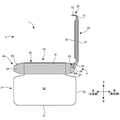
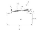
図1及び図2は、本実施形態に係る開閉式容器(以下、単に容器と呼ぶことがある)1の側面図である。これらの図に示すように、容器1は、容器本体2と、容器本体2の上部に形成されている開口S1を開閉するキャップ3とを有する。図1は、開口S1が開いた開状態を示しており、図2は、開口S1が閉じられた閉状態を示している。容器1は、後述するとおり閉状態での密閉性が高く、容器1の用途は特に限定されないが、食品等を保存するのに適している。Hereinafter, the openable / closable container according to the embodiment of the present invention will be described with reference to the drawings.
<1. Overall configuration of retractable container>
1 and 2 are side views of an openable container (hereinafter, may be simply referred to as a container) 1 according to the present embodiment. As shown in these figures, the
<2.各部の構成>
以下、各部の構成について詳細に説明する。なお、特に断らない限り、上、下、前(正面側)及び後(背面側)は、図1及び図2に示すとおり定義され、左右は、正面側から見て左右を意味する。また、後述するとおり、キャップ3のドア蓋30は回動によりその位置を変えるが、特に断らない限り、上、下、前(正面側)及び後(背面側)は、閉状態を基準として説明される。<2. Composition of each part>
Hereinafter, the configuration of each part will be described in detail. Unless otherwise specified, upper, lower, front (front side) and rear (back side) are defined as shown in FIGS. 1 and 2, and left and right mean left and right when viewed from the front side. Further, as will be described later, the position of the
<2−1.容器本体>
図3は、容器本体2単体の側面図である。容器本体2は、食品等の内容物を収容するための内部空間S2を規定する。容器本体2は、底面部21と、底面部21の周縁から起立する筒状の胴部22と、胴部22の上端から径方向内側に延びる肩部23と、肩部23の径方向の内側端から上方に延びるネック部24とを有する。本実施形態では、底面部21は平面視において概ね矩形であり、胴部22は角筒状である。ネック部24は、胴部22よりも径の小さい円筒状である。ネック部24は、容器本体2の開口S1を囲み、開口S1を規定する口部を形成する。従って、以下では、ネック部24を口部24と呼ぶことがある。開口S1は、内部空間S2に連通している。<2-1. Container body>
FIG. 3 is a side view of the
ネック部24の外周面には、周方向に沿って延びるリブ25が形成されている。より具体的には、リブ25は、ネック部24の中心軸に沿って螺旋状に延びており、後述するキャップ3に形成されているリブ45と螺号する。これにより、キャップ3は、容器本体2に対し着脱自在に取り付けられる。口部24は、キャップ3が取り付けられるキャップ3との連結部分となる。
容器本体2の材質は特に限定されないが、軽量性、強度、耐腐食性等の観点から、ゴム弾性を有さない硬質の合成樹脂から構成されることが好ましいが、ガラス製とすることもできる。本実施形態では、容器本体2は、AS(アクリロニトリルスチレン樹脂)製である。また、本実施形態では、上述の部21〜25は、一体的に構成されている。 The material of the
<2−2.キャップ>
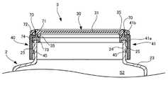
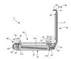
図4は、開状態のキャップ3の斜視図である。図5及び図6は、図4のA―A線に沿ったキャップ3と容器本体2の上部の断面図であり、図5は、開状態を示しており、図6は、閉状態を示している。図7及び図8は、図4のB−B線に沿ったキャップ3単体の断面図であり、図7は、開状態を示しており、図8は、閉状態を示している。以下、これらの図も参考にしつつ、キャップ3の構成について詳細に説明する。<2-2. Cap >
FIG. 4 is a perspective view of the
図4に示すとおり、キャップ3は、概ね円環状のフレーム40と、フレーム40にヒンジ式に連結される概ね円板状のドア蓋30とを有する。ドア蓋30はフレーム40に対し、開口S1が閉じられた閉位置と、開口S1が開いた開位置との間を回動する。図5及び図6に示すとおり、フレーム40は、容器本体2の口部24に対し着脱自在に取り付けられる。フレーム40は、口部24に取り付けられた状態で口部24を外側から囲み、口部24とともに開口S1を囲む周縁部を形成する。 As shown in FIG. 4, the
図4、図7及び図8に示すとおり、ドア蓋30は、概ね円板状の蓋本体31と、蓋本体31の後部からさらに背面側へ延びる板部材32とを有する。板部材32は、蓋本体31から離れるにつれてやや下方に向かうように傾斜している(図2及び図8参照)。板部材32の左右の両端部には、それぞれ図4の状態で径方向内側に延びる(閉状態では、下方に延びる)側壁部33a,33bが起立している。また、側壁部33a,33bの外面からは、それぞれ左右方向に外側に向かって延びる円柱状の突起34,34が突出している。突起34,34は、左右方向に延びる軸線に対し同軸に配置されている。 As shown in FIGS. 4, 7 and 8, the
ドア蓋30の材質は特に限定されないが、軽量性、強度、耐腐食性等の観点から、ゴム弾性を有さない硬質の合成樹脂から構成されることが好ましい。本実施形態では、ドア蓋30は、飽和ポリエステル製である。また、本実施形態では、ドア蓋30は、後述する第1延在部50とともに一体的に構成されている。 The material of the
一方、フレーム40は、概ね円環状のベースフレーム41と、ベースフレーム41の後部からさらに背面側へ延びる左右一対の側壁部42a,42bとを有する。側壁部42a,42bの下部は、同じくベースフレーム41の後部からさらに背面側へ延びる下面部43(図7及び図8参照)を介して接続されている。また、側壁部42a,42bには、それぞれ孔44,44が形成されている。孔44,44は、左右方向に延びる軸線に対し同軸に配置されている。 On the other hand, the
フレーム40の材質は特に限定されないが、軽量性、強度、耐腐食性等の観点から、ゴム弾性を有さない硬質の合成樹脂から構成されることが好ましい。本実施形態では、フレーム40は、ポリプロピレン製である。また、本実施形態では、フレーム40は、後述する第2延在部60とともに一体的に構成されている。 The material of the
ドア蓋30の側壁部33a,33bは、それぞれ側壁部33a,33bの外面がフレーム40の側壁部42a,42bの内面に対向するように、側壁部42a,42bの間に配置されている。また、ドア蓋30の突起34,34は、それぞれ側壁部42a,42bの孔44,44内に挿入されている。このため、突起34,34は、ドア蓋30とフレーム40とを連結するヒンジ機構4の回動軸を形成し、孔44,44は、この回動軸を受け取る軸受を形成する。すなわち、板部材32、側壁部33a,33b、突起34,34、側壁部42a,42b、孔44,44及び下面部43により、ヒンジ機構4が形成されている。これにより、ドア蓋30は、フレーム40に対しヒンジ式に連結され、フレーム40に対し回動可能となる。蓋本体31の周縁部は、閉状態においてベースフレーム41の上端部41bに受け取られ(ただし、図2に示すように、両者の間には若干の隙間が存在する)、このとき、蓋本体31が開口S1を上部から覆う。 The
図4〜図6に示すように、ベースフレーム41は、概ね厚みが一定の周壁部41aを有する。周壁部41aの内周面には、周方向に沿って延びるリブ45が形成されている。より具体的には、リブ45は、周壁部41aの中心軸に沿って螺旋状に延びており、前述した口部24に形成されるリブ25と螺号する。 As shown in FIGS. 4 to 6, the
ベースフレーム41の上端部41bは、周壁部41aの上部に位置し、周壁部41aの内周面よりも内側に突出している。すなわち、ベースフレーム41の上部には、ベースフレーム41の内側から見て、段差が形成されている。そして、この段差に引っ掛けられるようにして、ベースフレーム41には円環状のガスケット70が取り付けられている。 The
図4〜図6に示すように、ガスケット70は、円環状の本体部71と、本体部71の上面の中央付近から上方に延びる円環状の上部72とを有する。本体部71は、縦断面が概ね矩形状である。また、ガスケット70は、本体部71の径方向の内側端から下方に延びる円環状の内側下部73と、本体部71の径方向の外側端から下方に延びる円環状の外側下部74とを有する。図5及び図6に示すように、本体部71と上部72とにより形成される段差(径方向外側に面する段差)は、ベースフレーム41の上端部41bと周壁部41aとにより形成される段差とかみ合うように配置され、噛合面が互いにしっかりと接触する。また、本体部71及び外側下部74の外周面は、周壁部41aの内周面にしっかりと接触する。また、フレーム40が容器本体2に取り付けられた状態で、本体部71の下面は、容器本体2の口部24の上端部にしっかりと接触する。このようにガスケット70は、フレーム40が容器本体2に取り付けられた状態で口部24とベースフレーム41との間に形成される隙間に挟まれ、当該隙間を埋め、当該隙間をシールする。 As shown in FIGS. 4 to 6, the
また、図6に示すように、ガスケット70は、ドア蓋30が閉位置にあるときにベースフレーム41とドア蓋30との隙間に挟まれ、当該隙間をシールする。より具体的には、ドア蓋30は、蓋本体31の下面から垂下する円環状の脚部35を有する。脚部35は、蓋本体31の外周縁のやや内側に位置する。そして、閉状態においては、本体部71と上部72とにより形成される段差(径方向内側に面する段差)は、蓋本体31と脚部35とにより形成される段差(径方向外側に面する段差)とかみ合い、噛合面が互いにしっかりと接触する。 Further, as shown in FIG. 6, the
以上の構成のガスケット70により、ドア蓋30が閉位置にあるときに開口S1が完全に閉じられ、容器本体2の内部空間S2が外部から密閉される。また、本実施形態では、1つのガスケット70が、フレーム40とドア蓋30との隙間に加え、容器本体2とフレーム40との隙間をシールする。従って、部品点数が少なく、シンプルな構造でありながら、密閉性の高い容器1が実現される。 With the
図4、図7及び図8に示すとおり、キャップ3は、ドア蓋30を閉位置に維持するためのロック機構5を有する。ロック機構5は、蓋本体31から延在する第1延在部50と、ベースフレーム41から延在する第2延在部60とから構成される。第1延在部50は、蓋本体31の前部からやや正面側へ突出した突出部51と、突出部51の正面側から下方へ延びる板部材52とを有する。板部材52の正面には、左右方向の中央付近に爪53が形成されている。一方、第2延在部60は、ベースフレーム41の前部からやや正面側へ突出した突出部61と、突出部61から上方へ延びる板部材62とを有する。また、第2延在部60は、板部材62の上端に連続する押しボタン63を有する。押しボタン63の背面には、左右方向の中央付近に爪64が形成されている。また、第2延在部60は、ベースフレーム41の前部に連続し、以上の部61〜64を囲む周壁部65を有する。周壁部65は、これらの部61〜64と干渉しない位置に配置されている。 As shown in FIGS. 4, 7 and 8, the
ドア蓋30が開位置から前方へ倒れ、閉位置に近づくと、板部材52は、板部材62とベースフレーム41との間の空間に挿入される。このとき、爪53が爪64を押し、これにより板部材62が弾性変形しやや前方へ倒れる。そして、この状態から板部材52がさらに深くまで進むと、爪53が爪64を乗越える。このとき、板部材62が弾性力により元の位置に復帰し、両爪64,53が互いにかみ合う。これにより、爪53が爪64に引っ掛かり、ドア蓋30が閉位置に維持されるロック状態が形成される。 When the
ロック状態で使用者が押しボタン63を指で押圧すると、再び板部材62が弾性変形してやや前方へ倒れる。これにより、爪53と爪64とがかみ合みあったロック状態が解除され、解除状態となる。以上のとおり、ロック機構5は、ロック状態と解除状態とを切り替えることができる。 When the user presses the
ロック状態が解除されると、ドア蓋30は回動軸34周りを自動的に回動し、開位置に復帰する。より具体的には、キャップ3は、図4、図7及び図8に示すとおり、上述したヒンジ機構4と協働する付勢部材80をさらに有している。付勢部材80は、ドア蓋30を開位置に向かう方向に付勢する。なお、本実施形態では、ドア蓋30は開位置にあるときに概ね上下方向に起立する。 When the locked state is released, the
付勢部材80は、ガスケット70と同じ材料からなり、ガスケット70と一体的に構成されている。付勢部材80及びガスケット70は、弾性材料からなり、ゴム弾性を有する。付勢部材80及びガスケット70は、典型的にはエラストマー(ゴム又は熱可塑性エラストマー)から構成され、本実施形態では、シリコーンゴム製である。ガスケット70及び付勢部材80は、柔らかく変形が容易であるため、キャップ2のその他の部位から取り外すことができる。 The urging
付勢部材80は、ガスケット70の後部に連続しており、ガスケット70の後部からやや背面側へ突出した突出部81を有する。なお、図4に示すとおり、ベースフレーム41の上端部41b及び周壁部41aの上部は概ね全周に亘って延びているが、後部において一部が切り欠かれている。突出部81は、この切り欠きを通り、ベースフレーム41の径方向内側から外側に達する。 The urging
図7及び図8に示すように、付勢部材80は、突出部81の後部から下方に延びる壁部82と、壁部82の下部から折れ曲がって後方へ延びるシート部83とをさらに有する。壁部82の径方向の内側面は、ベースフレーム41の外周面にしっかりと接触する。一方、シート部83の外面は、ベースフレーム41から後方へ延びる下面部43の上面と、蓋本体31から後方へ延びる板部材32の内面とにしっかりと接触する。板部材32の内面には、突起36が形成されている。一方、シート部83は概ね矩形であるが、その先端部には、突起36を受け取るための切り欠きが形成されている。そして、この切り欠きに突起36が挿入されることにより、シート部83の位置が固定される。この状態で、シート部83は突起36にしっかりと接触する。 As shown in FIGS. 7 and 8, the urging
図8に示すとおり、シート部83は、ドア蓋30が閉位置にあるときに、板部材32と下面部43との間の空間に折り畳まれて収容される。しかしながら、ロック状態が解除されると、折り畳まれていたシート部83は、元のより平らな形状に戻ろうとする弾性力により板部材32を押す。これにより、板部材32に連結されている蓋本体31が開く方向に自動的に回動する。以上のとおり、容器1は、押しボタン63を押すだけでドア蓋30を開くことができるワンプッシュオープン式に構成されており、操作性に優れている。なお、ドア蓋30が所定の角度まで回動すると、ドア蓋30の側壁部33a,33bがフレーム40の下面部43に接触し、それ以上の回転が規制される。 As shown in FIG. 8, the
シート部83は、ガスケット70及び付勢部材80がキャップ3の他の部分から取り外された状態では平板状である。そして、シート部83は、閉状態において折り畳まれているときのみならず、図7に示すとおり開状態においても湾曲している。そのため、付勢部材80は、ドア蓋30に対し開状態においてもドア蓋30をさらに開く方向に力を加えている。従って、例えば、使用時に容器1を傾ける等しても、ドア蓋30が自重により倒れ難い。よって、使用時にドア蓋30が大きくパタパタと揺れることがなく、容器1は使い勝手に優れている。 The
また、図4、図7及び図8に示すとおり、シート部83の内面上には、部分的に肉厚部84が形成されている。この肉厚部84は、シート部83が元の形状に戻ろうとする弾性力を高めることができる。また、この肉厚部84は、シート部83が開状態及び閉状態並びにこれら状態の間の状態において、常に同様の形状に変形することを助長する。従って、常に同じような開状態及び閉状態を実現することができる。 Further, as shown in FIGS. 4, 7 and 8, a
<3.変形例>
以上、本発明の一実施形態について説明したが、本発明は上記実施形態に限定されるものではなく、その趣旨を逸脱しない限りにおいて、種々の変更が可能である。例えば、以下の変更が可能である。また、以下の変形例の要旨は、適宜組み合わせることができる。<3. Modification example>
Although one embodiment of the present invention has been described above, the present invention is not limited to the above embodiment, and various modifications can be made without departing from the spirit of the present invention. For example, the following changes can be made. In addition, the gist of the following modified examples can be combined as appropriate.
<3−1>
上記実施形態では、ガスケット70が、容器本体2とフレーム40との隙間と、フレーム40とドア蓋30との隙間の両方をシールする役割を担っていたが、両隙間を埋めるためのガスケットを別個に設けてもよい。この場合において、フレーム40とドア蓋30との隙間を埋めるガスケットは、ベースフレーム41ではなく、蓋本体31に取り付けてもよい。また、容器本体2とフレーム40との隙間をシールするガスケットは省略することもできる。<3-1>
In the above embodiment, the
<3−2>
容器本体2に対するキャップ2の取り付け構造は、上述したもの(螺号)に限られず、嵌め込み式にする等、任意の構造を採用することができる。また、容器本体2に対しキャップ2を取り付ける構造とせず、ドア蓋30を容器本体2の口部24に直接ヒンジ式に連結するように構成することもできる。<3-2>
The attachment structure of the
<3−3>
上記実施形態では、口部24及びフレーム40が円環状に形成されていたが、口部24及びフレーム40を角環状に形成することもできる。<3-3>
In the above embodiment, the
1 開閉式容器
2 容器本体
3 キャップ
4 ヒンジ機構
5 ロック機構
24 口部
30 ドア蓋
40 フレーム
50 第1延在部
60 第2延在部
70 ガスケット
80 付勢部材
S1 開口1
Claims (11)
Translated fromJapanese前記開口を開閉するキャップと
を備え、
前記キャップは、
前記口部に対し着脱自在に取り付けられる環状のフレームと、
前記フレームにヒンジ式に連結され、前記開口が閉じられた閉位置と、前記開口が開いた開位置との間を回動するドア蓋と、
前記フレーム又は前記ドア蓋に取り付けられ、弾性材料からなり、前記ドア蓋が前記閉位置にあるときに前記フレームと前記ドア蓋との隙間に挟まれ、当該隙間をシールするガスケットと、
前記ガスケットと同じ弾性材料からなり、前記ガスケットと一体的に構成され、前記ドア蓋を前記開位置に向かう方向に付勢する付勢部材と
を含み、
前記付勢部材には、前記付勢部材の他の部分よりも肉厚の肉厚部と、前記ドア蓋に接触しており、前記ドア蓋が前記閉位置にあるときに折り畳まれる部分と、が形成され、
前記肉厚部は、前記折り畳まれる部分と前記ガスケットとの間に形成される、
開閉式容器。A container body with a mouth that defines an opening,
With a cap that opens and closes the opening
The cap
An annular frame that can be detachably attached to the mouth and
A door lid that is hinged to the frame and rotates between a closed position where the opening is closed and an open position where the opening is open.
A gasket that is attached to the frame or the door lid and is made of an elastic material, is sandwiched between the frame and the door lid when the door lid is in the closed position, and seals the gap.
It is made of the same elastic material as the gasket, is integrally formed with the gasket, and includes an urging member that urges the door lid in a direction toward the open position.
The urging member includes a thick portion that is thicker than the other portion of the urging member, a portionthat is in contact with the door lid and is folded when the door lid is in the closed position. Is formed,
The thick portion, Ruis formed between said portion and the gasket are folded,
Openable container.
請求項1に記載の開閉式容器。The gasket is attached to the frame.
The retractable container according to claim 1.
請求項2に記載の開閉式容器。The gasket is sandwiched between the mouth and the frame with the frame attached to the mouth, and seals the gap.
The retractable container according to claim 2.
請求項1から3のいずれかに記載の開閉式容器。The cap further includes a locking mechanism that switches between a locked state in which the door lid is maintained in the closed position and an released state in which the locked state is released.
The retractable container according to any one of claims 1 to 3.
請求項4に記載の開閉式容器。The locking mechanism has a first extending portion extending from the door lid and a second extending portion extending from the frame and engaging with the first extending portion in the locked state.
The retractable container according to claim 4.
前記周縁部にヒンジ式に連結され、前記開口が閉じられた閉位置と、前記開口が開いた開位置との間を回動するドア蓋と、
前記周縁部又は前記ドア蓋に取り付けられ、弾性材料からなり、前記ドア蓋が前記閉位置にあるときに前記周縁部と前記ドア蓋との隙間に挟まれ、当該隙間をシールするガスケットと、
前記ガスケットと同じ弾性材料からなり、前記ガスケットと一体的に構成され、前記ドア蓋を前記開位置に向かう方向に付勢する付勢部材と
を備え、
前記付勢部材には、前記付勢部材の他の部分よりも肉厚の肉厚部と、前記ドア蓋に接触しており、前記ドア蓋が前記閉位置にあるときに折り畳まれる部分と、が形成され、
前記肉厚部は、前記折り畳まれる部分と前記ガスケットとの間に形成される、
開閉式容器。The container body including the peripheral edge surrounding the opening,
A door lid that is hinged to the peripheral edge and rotates between a closed position where the opening is closed and an open position where the opening is open.
A gasket that is attached to the peripheral edge portion or the door lid and is made of an elastic material, is sandwiched between the peripheral edge portion and the door lid when the door lid is in the closed position, and seals the gap.
It is made of the same elastic material as the gasket, is integrally formed with the gasket, and includes an urging member that urges the door lid in a direction toward the open position.
The urging member includes a thick portion that is thicker than the other portion of the urging member, a portionthat is in contact with the door lid and is folded when the door lid is in the closed position. Is formed,
The thick portion, Ruis formed between said portion and the gasket are folded,
Openable container.
をさらに備える、
請求項6に記載の開閉式容器。A locking mechanism for switching between a locked state in which the door lid is maintained in the closed position and an released state in which the locked state is released is further provided.
The retractable container according to claim 6.
請求項7に記載の開閉式容器。The locking mechanism has a first extending portion extending from the door lid and a second extending portion extending from the peripheral edge portion and engaging with the first extending portion in the locked state.
The retractable container according to claim 7.
請求項1から8のいずれかに記載の開閉式容器。Wherein the biasing memberbiases the door cover in a direction toward the open position by the elastic force of returning to its original shape,
The retractable container according to any one of claims 1 to 8.
請求項1から9のいずれかに記載の開閉式容器。The elastic material is an elastomer.
The retractable container according to any one of claims 1 to 9.
請求項10に記載の開閉式容器。
The elastic material is silicone rubber.
The retractable container according to claim 10.
Priority Applications (3)
| Application Number | Priority Date | Filing Date | Title |
|---|---|---|---|
| JP2017029471AJP6935859B2 (en) | 2017-02-20 | 2017-02-20 | Retractable container |
| KR1020170113975AKR20180096471A (en) | 2017-02-20 | 2017-09-06 | Opening and closing type container |
| US15/842,287US20180237190A1 (en) | 2017-02-20 | 2017-12-14 | Closable container |
Applications Claiming Priority (1)
| Application Number | Priority Date | Filing Date | Title |
|---|---|---|---|
| JP2017029471AJP6935859B2 (en) | 2017-02-20 | 2017-02-20 | Retractable container |
Publications (2)
| Publication Number | Publication Date |
|---|---|
| JP2018135107A JP2018135107A (en) | 2018-08-30 |
| JP6935859B2true JP6935859B2 (en) | 2021-09-15 |
Family
ID=63166407
Family Applications (1)
| Application Number | Title | Priority Date | Filing Date |
|---|---|---|---|
| JP2017029471AActiveJP6935859B2 (en) | 2017-02-20 | 2017-02-20 | Retractable container |
Country Status (3)
| Country | Link |
|---|---|
| US (1) | US20180237190A1 (en) |
| JP (1) | JP6935859B2 (en) |
| KR (1) | KR20180096471A (en) |
Families Citing this family (17)
| Publication number | Priority date | Publication date | Assignee | Title |
|---|---|---|---|---|
| AU201713332S (en)* | 2017-06-02 | 2017-06-15 | Pact Group Holdings Nz Ltd | Lid for a container |
| CN111343888B (en)* | 2017-10-06 | 2022-12-02 | 岩崎工业株式会社 | Cover body and drink container with same |
| US11083847B2 (en) | 2018-01-26 | 2021-08-10 | Becton, Dickinson And Company | Flush syringe with flip cap |
| US11273298B2 (en) | 2018-04-10 | 2022-03-15 | Becton, Dickinson And Company | Universal single-use cap for male and female connectors |
| CA3145028A1 (en) | 2019-08-08 | 2021-02-11 | Chang JIANG | Universal cap with pressure seal |
| CA3090501A1 (en)* | 2019-08-20 | 2021-02-20 | Thermos L.L.C. | Lid for food container |
| US11975168B2 (en) | 2019-11-18 | 2024-05-07 | Becton, Dickinson And Company | Disinfectant cap |
| US11890445B2 (en) | 2019-12-23 | 2024-02-06 | Becton, Dickinson And Company | Universal disinfection cap |
| US11857753B2 (en) | 2019-12-23 | 2024-01-02 | Becton, Dickinson And Company | Disinfecting syringe tip |
| US12029828B2 (en) | 2020-03-05 | 2024-07-09 | Becton, Dickinson And Company | Disinfection cap |
| US11890446B2 (en) | 2020-04-17 | 2024-02-06 | Becton, Dickinson And Company | Cap for male and female threaded fittings |
| US11969572B2 (en) | 2020-04-17 | 2024-04-30 | Becton, Dickinson And Company | Disinfection cap |
| US12383719B2 (en) | 2020-04-17 | 2025-08-12 | Becton, Dickinson And Company | Disinfecting cap with re-use prevention |
| US12005223B2 (en) | 2020-04-17 | 2024-06-11 | Becton, Dickinson And Company | Disinfection cap |
| US12280921B2 (en)* | 2020-08-20 | 2025-04-22 | Sidel Participations Sas | Hinged closure |
| CN115402623B (en)* | 2022-07-25 | 2024-06-25 | 深圳市大满包装有限公司 | Can lid, can manufacturing method and can lid, can |
| KR102751235B1 (en)* | 2022-09-02 | 2025-01-09 | 주식회사 올테크코리아 | Tumbler cap |
Family Cites Families (11)
| Publication number | Priority date | Publication date | Assignee | Title |
|---|---|---|---|---|
| JP3308099B2 (en)* | 1993-06-16 | 2002-07-29 | 花王株式会社 | cap |
| JP3669758B2 (en)* | 1995-06-15 | 2005-07-13 | ユニ・チャーム株式会社 | Lid device |
| FR2752820B1 (en)* | 1996-08-29 | 1998-09-25 | Oreal | DISTRIBUTION CAPSULE WITH IMPROVED SEALING |
| FR2752821B1 (en)* | 1996-08-29 | 1998-09-25 | Oreal | DISPENSING CAPSULE WITH IMPROVED GRIPPING MEANS |
| DE19832799B4 (en)* | 1998-07-21 | 2006-03-02 | Kunststoffwerk Kutterer Gmbh & Co. Kg | Hinged cap |
| FR2855815B1 (en)* | 2003-06-06 | 2006-03-17 | Zebra Company | UNLOCKABLE COVER CAP WITH ELASTIC RECALL |
| JP4697740B2 (en)* | 2006-01-31 | 2011-06-08 | 株式会社吉野工業所 | Airtight container with lid |
| JP4925165B2 (en) | 2006-01-31 | 2012-04-25 | 株式会社吉野工業所 | Airtight container with lid |
| JP4775070B2 (en)* | 2006-03-29 | 2011-09-21 | 大日本印刷株式会社 | One-touch container |
| JP4921109B2 (en)* | 2006-10-20 | 2012-04-25 | ユニ・チャーム株式会社 | Moisturizing container |
| EP2548466B1 (en)* | 2010-03-18 | 2016-04-13 | Yong Jun Lee | Sealing ring structure of a cosmetic container |
- 2017
- 2017-02-20JPJP2017029471Apatent/JP6935859B2/enactiveActive
- 2017-09-06KRKR1020170113975Apatent/KR20180096471A/ennot_activeWithdrawn
- 2017-12-14USUS15/842,287patent/US20180237190A1/ennot_activeAbandoned
Also Published As
| Publication number | Publication date |
|---|---|
| KR20180096471A (en) | 2018-08-29 |
| US20180237190A1 (en) | 2018-08-23 |
| JP2018135107A (en) | 2018-08-30 |
Similar Documents
| Publication | Publication Date | Title |
|---|---|---|
| JP6935859B2 (en) | Retractable container | |
| JP6649838B2 (en) | Cap unit and beverage container | |
| JP6681745B2 (en) | Cap unit and beverage container | |
| JP5650284B1 (en) | Beverage container hinge structure | |
| JP6839748B2 (en) | Cap unit and beverage container | |
| US11014707B2 (en) | Resealable container | |
| JP2014218258A (en) | Plug body for beverage container | |
| JP2015013674A (en) | Beverage container | |
| JP7090489B2 (en) | Cap unit and container with cap | |
| JP2021050009A (en) | Lock mechanism for beverage container and beverage container | |
| JP2010089807A (en) | Synthetic resin cap | |
| JP7508059B2 (en) | Compact container | |
| JP2021059369A (en) | Cap unit and container with cap | |
| JP4375610B2 (en) | cap | |
| JP2013173550A (en) | Plug body of beverage container | |
| JP2014076377A (en) | Beverage container plug | |
| JP3201676U (en) | Beverage container | |
| TWI822272B (en) | Lid components and beverage containers | |
| JP7634457B2 (en) | Cap unit and beverage container | |
| JP4993716B2 (en) | Beverage container | |
| KR102731844B1 (en) | Airtight container | |
| JP6434358B2 (en) | Caps and containers with caps | |
| JP6423846B2 (en) | Beverage container | |
| JP2024004083A (en) | Cap unit and container with cap | |
| CN117622700A (en) | Cap unit and beverage container |
Legal Events
| Date | Code | Title | Description |
|---|---|---|---|
| A80 | Written request to apply exceptions to lack of novelty of invention | Free format text:JAPANESE INTERMEDIATE CODE: A80 Effective date:20170317 | |
| A621 | Written request for application examination | Free format text:JAPANESE INTERMEDIATE CODE: A621 Effective date:20191212 | |
| A977 | Report on retrieval | Free format text:JAPANESE INTERMEDIATE CODE: A971007 Effective date:20201014 | |
| A131 | Notification of reasons for refusal | Free format text:JAPANESE INTERMEDIATE CODE: A131 Effective date:20201020 | |
| A521 | Request for written amendment filed | Free format text:JAPANESE INTERMEDIATE CODE: A523 Effective date:20201221 | |
| A131 | Notification of reasons for refusal | Free format text:JAPANESE INTERMEDIATE CODE: A131 Effective date:20210323 | |
| A521 | Request for written amendment filed | Free format text:JAPANESE INTERMEDIATE CODE: A523 Effective date:20210517 | |
| TRDD | Decision of grant or rejection written | ||
| A01 | Written decision to grant a patent or to grant a registration (utility model) | Free format text:JAPANESE INTERMEDIATE CODE: A01 Effective date:20210713 | |
| A61 | First payment of annual fees (during grant procedure) | Free format text:JAPANESE INTERMEDIATE CODE: A61 Effective date:20210810 | |
| R150 | Certificate of patent or registration of utility model | Ref document number:6935859 Country of ref document:JP Free format text:JAPANESE INTERMEDIATE CODE: R150 | |
| R250 | Receipt of annual fees | Free format text:JAPANESE INTERMEDIATE CODE: R250 |