JP6935830B2 - Rapid administration - Google Patents
Rapid administrationDownload PDFInfo
- Publication number
- JP6935830B2 JP6935830B2JP2020108929AJP2020108929AJP6935830B2JP 6935830 B2JP6935830 B2JP 6935830B2JP 2020108929 AJP2020108929 AJP 2020108929AJP 2020108929 AJP2020108929 AJP 2020108929AJP 6935830 B2JP6935830 B2JP 6935830B2
- Authority
- JP
- Japan
- Prior art keywords
- drug solution
- flow path
- rapid administration
- mode
- administration
- Prior art date
- Legal status (The legal status is an assumption and is not a legal conclusion. Google has not performed a legal analysis and makes no representation as to the accuracy of the status listed.)
- Active
Links
- 229940079593drugDrugs0.000claimsdescription134
- 239000003814drugSubstances0.000claimsdescription134
- 239000000126substanceSubstances0.000claimsdescription54
- 230000037452primingEffects0.000claimsdescription25
- 230000007704transitionEffects0.000claimsdescription11
- 239000000243solutionSubstances0.000description154
- 238000003825pressingMethods0.000description11
- 239000007788liquidSubstances0.000description10
- 230000001954sterilising effectEffects0.000description5
- 238000004659sterilization and disinfectionMethods0.000description5
- 230000001276controlling effectEffects0.000description4
- 238000000034methodMethods0.000description4
- 210000004204blood vesselAnatomy0.000description3
- 230000036592analgesiaEffects0.000description2
- 229940035676analgesicsDrugs0.000description2
- 239000000730antalgic agentSubstances0.000description2
- 239000002246antineoplastic agentSubstances0.000description2
- 229940041181antineoplastic drugDrugs0.000description2
- 230000008602contractionEffects0.000description2
- 229920000728polyesterPolymers0.000description2
- -1polyethylenePolymers0.000description2
- 238000001356surgical procedureMethods0.000description2
- 229920003051synthetic elastomerPolymers0.000description2
- 206010002091AnaesthesiaDiseases0.000description1
- IAYPIBMASNFSPL-UHFFFAOYSA-NEthylene oxideChemical compoundC1CO1IAYPIBMASNFSPL-UHFFFAOYSA-N0.000description1
- HTTJABKRGRZYRN-UHFFFAOYSA-NHeparinChemical compoundOC1C(NC(=O)C)C(O)OC(COS(O)(=O)=O)C1OC1C(OS(O)(=O)=O)C(O)C(OC2C(C(OS(O)(=O)=O)C(OC3C(C(O)C(O)C(O3)C(O)=O)OS(O)(=O)=O)C(CO)O2)NS(O)(=O)=O)C(C(O)=O)O1HTTJABKRGRZYRN-UHFFFAOYSA-N0.000description1
- 244000043261Hevea brasiliensisSpecies0.000description1
- 206010028980NeoplasmDiseases0.000description1
- 239000004952PolyamideSubstances0.000description1
- 239000004698PolyethyleneSubstances0.000description1
- 239000004743PolypropyleneSubstances0.000description1
- 230000037005anaesthesiaEffects0.000description1
- 230000000202analgesic effectEffects0.000description1
- 230000005540biological transmissionEffects0.000description1
- 201000011510cancerDiseases0.000description1
- 238000007796conventional methodMethods0.000description1
- 238000001647drug administrationMethods0.000description1
- 239000013013elastic materialSubstances0.000description1
- 229920001971elastomerPolymers0.000description1
- 239000000806elastomerSubstances0.000description1
- 238000010894electron beam technologyMethods0.000description1
- 238000004388gamma ray sterilizationMethods0.000description1
- 229960002897heparinDrugs0.000description1
- 229920000669heparinPolymers0.000description1
- 238000001802infusionMethods0.000description1
- 238000002347injectionMethods0.000description1
- 239000007924injectionSubstances0.000description1
- 239000000463materialSubstances0.000description1
- 229920003052natural elastomerPolymers0.000description1
- 229920001194natural rubberPolymers0.000description1
- 230000036407painEffects0.000description1
- 229920000058polyacrylatePolymers0.000description1
- 229920002647polyamidePolymers0.000description1
- 239000004417polycarbonateSubstances0.000description1
- 229920000515polycarbonatePolymers0.000description1
- 229920000573polyethylenePolymers0.000description1
- 229920001195polyisoprenePolymers0.000description1
- 229920000193polymethacrylatePolymers0.000description1
- 229920001155polypropylenePolymers0.000description1
- 229920002635polyurethanePolymers0.000description1
- 239000004814polyurethaneSubstances0.000description1
- 239000004800polyvinyl chlorideSubstances0.000description1
- 229920000915polyvinyl chloridePolymers0.000description1
- 230000001105regulatory effectEffects0.000description1
- 239000011347resinSubstances0.000description1
- 229920005989resinPolymers0.000description1
- 239000005060rubberSubstances0.000description1
- 229920002379silicone rubberPolymers0.000description1
- 239000004945silicone rubberSubstances0.000description1
- 239000005061synthetic rubberSubstances0.000description1
Images


Classifications
- A—HUMAN NECESSITIES
- A61—MEDICAL OR VETERINARY SCIENCE; HYGIENE
- A61M—DEVICES FOR INTRODUCING MEDIA INTO, OR ONTO, THE BODY; DEVICES FOR TRANSDUCING BODY MEDIA OR FOR TAKING MEDIA FROM THE BODY; DEVICES FOR PRODUCING OR ENDING SLEEP OR STUPOR
- A61M5/00—Devices for bringing media into the body in a subcutaneous, intra-vascular or intramuscular way; Accessories therefor, e.g. filling or cleaning devices, arm-rests
- A61M5/14—Infusion devices, e.g. infusing by gravity; Blood infusion; Accessories therefor
- A61M5/168—Means for controlling media flow to the body or for metering media to the body, e.g. drip meters, counters ; Monitoring media flow to the body
- A61M5/16804—Flow controllers
- A—HUMAN NECESSITIES
- A61—MEDICAL OR VETERINARY SCIENCE; HYGIENE
- A61M—DEVICES FOR INTRODUCING MEDIA INTO, OR ONTO, THE BODY; DEVICES FOR TRANSDUCING BODY MEDIA OR FOR TAKING MEDIA FROM THE BODY; DEVICES FOR PRODUCING OR ENDING SLEEP OR STUPOR
- A61M39/00—Tubes, tube connectors, tube couplings, valves, access sites or the like, specially adapted for medical use
- A61M39/08—Tubes; Storage means specially adapted therefor
- A—HUMAN NECESSITIES
- A61—MEDICAL OR VETERINARY SCIENCE; HYGIENE
- A61M—DEVICES FOR INTRODUCING MEDIA INTO, OR ONTO, THE BODY; DEVICES FOR TRANSDUCING BODY MEDIA OR FOR TAKING MEDIA FROM THE BODY; DEVICES FOR PRODUCING OR ENDING SLEEP OR STUPOR
- A61M39/00—Tubes, tube connectors, tube couplings, valves, access sites or the like, specially adapted for medical use
- A61M39/22—Valves or arrangement of valves
- A61M39/225—Flush valves, i.e. bypass valves for flushing line
- A—HUMAN NECESSITIES
- A61—MEDICAL OR VETERINARY SCIENCE; HYGIENE
- A61M—DEVICES FOR INTRODUCING MEDIA INTO, OR ONTO, THE BODY; DEVICES FOR TRANSDUCING BODY MEDIA OR FOR TAKING MEDIA FROM THE BODY; DEVICES FOR PRODUCING OR ENDING SLEEP OR STUPOR
- A61M39/00—Tubes, tube connectors, tube couplings, valves, access sites or the like, specially adapted for medical use
- A61M39/22—Valves or arrangement of valves
- A61M39/28—Clamping means for squeezing flexible tubes, e.g. roller clamps
- A61M39/281—Automatic tube cut-off devices, e.g. squeezing tube on detection of air
- A—HUMAN NECESSITIES
- A61—MEDICAL OR VETERINARY SCIENCE; HYGIENE
- A61M—DEVICES FOR INTRODUCING MEDIA INTO, OR ONTO, THE BODY; DEVICES FOR TRANSDUCING BODY MEDIA OR FOR TAKING MEDIA FROM THE BODY; DEVICES FOR PRODUCING OR ENDING SLEEP OR STUPOR
- A61M5/00—Devices for bringing media into the body in a subcutaneous, intra-vascular or intramuscular way; Accessories therefor, e.g. filling or cleaning devices, arm-rests
- A61M5/14—Infusion devices, e.g. infusing by gravity; Blood infusion; Accessories therefor
Landscapes
- Health & Medical Sciences (AREA)
- Heart & Thoracic Surgery (AREA)
- Hematology (AREA)
- Anesthesiology (AREA)
- Biomedical Technology (AREA)
- Engineering & Computer Science (AREA)
- Life Sciences & Earth Sciences (AREA)
- Animal Behavior & Ethology (AREA)
- General Health & Medical Sciences (AREA)
- Public Health (AREA)
- Veterinary Medicine (AREA)
- Pulmonology (AREA)
- Vascular Medicine (AREA)
- Infusion, Injection, And Reservoir Apparatuses (AREA)
Description
Translated fromJapanese本開示は、薬液投与装置の急速投与部に関し、特に、患者の制御による薬液の急速投与が可能な急速投与部に関する。 The present disclosure relates to a rapid administration unit of a drug solution administration device, and more particularly to a rapid administration unit capable of rapid administration of a drug solution under patient control.
手術後の患者への鎮痛剤の投与や、がん患者への抗がん剤の投与などの場合に、患者に持続的に薬液を注入する薬液の投与法がある。持続的な投与の場合、通常は0.5mL/h〜10mL/h程度の流速で、半日から数日程度の期間投与が行われる。 There is a method of administering a drug solution that continuously injects a drug solution into a patient in the case of administration of an analgesic to a patient after surgery or administration of an anticancer drug to a cancer patient. In the case of continuous administration, administration is usually carried out at a flow rate of about 0.5 mL / h to 10 mL / h for a period of about half a day to several days.
持続的な投与の場合、薬液の投与量は基本的に一定とするが、薬液の投与量を一時的に増加させる急速投与を行いたい場合がある。例えば、外科手術後の鎮痛剤の投与の場合、患者が感じる痛みの程度に応じて鎮痛剤の投与量を一時的に増加させることがある。このような急速投与の実施は医師の管理の下に行われるが、近年では限られた範囲内において患者自らが行う、自己調節鎮痛法(PCA、Patient Controlled Analgesia)も行われている。 In the case of continuous administration, the dose of the drug solution is basically constant, but there are cases where it is desired to perform rapid administration in which the dose of the drug solution is temporarily increased. For example, in the case of administration of analgesics after surgery, the dose of analgesics may be temporarily increased depending on the degree of pain felt by the patient. Such rapid administration is performed under the supervision of a doctor, but in recent years, self-regulated analgesia (PCA, Patient Controlled Analgesia), which is performed by the patient himself within a limited range, has also been performed.
患者自らが急速投与の操作を行う場合には、操作が簡単で且つ過剰投与を防ぐための十分な安全機構を有する薬液投与装置が必要とされる。急速投与が可能な薬液投与装置として、送出量を制御可能な精密輸液ポンプを用いるものと、バルーンの収縮力を用いたバルーンポンプと、流量調整手段を有する薬液ラインとを組み合わせたものとがある。バルーンポンプを用いた薬液投与装置は、操作が簡単であるという利点がある。また、電源を必要としないため、持ち運びが容易な薬液投与装置を実現できるという利点がある。 When the patient himself performs the operation of rapid administration, a drug solution administration device that is easy to operate and has a sufficient safety mechanism to prevent overdose is required. As a drug solution administration device capable of rapid administration, there are one that uses a precision infusion pump that can control the delivery amount, and one that combines a balloon pump that uses the contractile force of a balloon and a drug solution line that has a flow rate adjusting means. .. The drug solution administration device using a balloon pump has an advantage that it is easy to operate. In addition, since it does not require a power source, there is an advantage that a drug solution administration device that is easy to carry can be realized.
バルーンポンプを用いた薬液投与装置において投与量を一時的に変更する方法として、例えば一定量の薬液を貯留するサブリザーバを有する急速投与部を薬液ラインに接続する方法がある(例えば、特許文献1を参照。)。サブリザーバに貯留した薬液を薬液ラインに送出することにより、一時的に投与量を増大させることができる。薬液を送出したサブリザーバに、薬液ラインを通じて徐々に薬液が再貯留されるようにすれば、薬液の連続注入ができないロックアウトタイムを設けることができ、薬液の過剰投与を防ぐこともできる。 As a method of temporarily changing the dose in a drug solution administration device using a balloon pump, for example, there is a method of connecting a rapid administration section having a sub-reservoir for storing a certain amount of drug solution to a drug solution line (for example, Patent Document 1). reference.). The dose can be temporarily increased by delivering the drug solution stored in the sub-reservoir to the drug solution line. If the drug solution is gradually re-stored in the sub-reservoir to which the drug solution is delivered through the drug solution line, a lockout time during which continuous injection of the drug solution is not possible can be provided, and overdose of the drug solution can be prevented.
しかしながら、従来のサブリザーバを設ける方法は、使用前のプライミングに手間がかかるという問題がある。例えば、バルーンポンプにより、薬液投与ラインをプライミングする。急速投与部は、注射器等を用いて薬液を注入して別途プライミングを行い、急速投与部と薬液投与ラインとを接続する。このように、コネクタの付け外しや、注射器を用いた薬液の注入等の煩雑な操作が求められる。コネクタの付け外しを避けるために逆止弁を有するポートを設けることもできるが、この場合にも注射器による薬液注入が必要である。また、ポートを設けることによりコストも増加する。 However, the conventional method of providing a sub-reservoir has a problem that priming before use takes time and effort. For example, a balloon pump is used to prime the drug solution administration line. The rapid administration unit injects the drug solution using a syringe or the like and performs priming separately to connect the rapid administration unit and the drug solution administration line. In this way, complicated operations such as attaching / detaching the connector and injecting the drug solution using a syringe are required. A port with a check valve can be provided to avoid attaching and detaching the connector, but in this case as well, it is necessary to inject the drug solution with a syringe. In addition, the cost is increased by providing the port.
本開示の課題は、急速投与を禁止するロックアウトタイムの設定が可能で且つプライミングが容易な薬液投与装置を実現できるようにすることである。 An object of the present disclosure is to realize a drug solution administration device in which a lockout time for prohibiting rapid administration can be set and priming is easy.
薬液投与装置の一態様は、薬液の流量を制御する流量制御部を有する主流路から分岐した、薬液の急速投与部を備え、急速投与部は、流量制御部よりも基端側において主流路と接続された流入流路と、流量制御部よりも先端側において主流路と接続された流出流路と、流入流路と流出流路との間に接続され、薬液を貯留する薬液貯留部と、薬液貯留部への薬液の貯留及び薬液貯留部からの薬液の送出を制御する制御部とを有し、流入流路は、第1の流路と、第1の流路よりも流路断面積が小さい第2の流路とを有し、制御部は、第1の流路を閉止する第1の閉止部と、流出流路を開閉可能に閉止する第2の閉止部とを有している。 One aspect of the drug solution administration device includes a rapid administration section of the drug solution branched from the main flow path having a flow rate control unit for controlling the flow rate of the drug solution, and the rapid administration section has a main flow path on the proximal end side of the flow rate control unit. The connected inflow flow path, the outflow flow path connected to the main flow path on the tip side of the flow rate control unit, the chemical solution storage unit connected between the inflow flow path and the outflow flow path, and the chemical solution storage unit for storing the chemical solution. It has a control unit that controls the storage of the drug solution in the drug solution storage section and the delivery of the drug solution from the drug solution storage section, and the inflow flow path has the first flow path and the cross-sectional area of the flow path rather than the first flow path. The control unit has a first closing portion that closes the first flow path and a second closing portion that closes the outflow flow path so as to be openable and closable. There is.
薬液投与装置の一態様において、急速投与部は、第1の閉止部及び第2の閉止部を開放した状態として、急速投与部を薬液で満たすプライミングモードと、第1の閉止部及び第2の閉止部を閉止した状態として、薬液貯留部へ薬液を貯留する薬液貯留モードと、第1の閉止部を閉止した状態を維持し且つ第2の閉止部を開放した状態として、薬液貯留部に貯留された薬液を送出する急速投与モードとを有し、制御部は、プライミングモードから薬液貯留モードへの移行と、薬液貯留モードと急速投与モードとの間の移行とを制御するようにできる。 In one aspect of the drug solution administration device, the rapid administration section has a priming mode in which the rapid administration section is filled with the drug solution with the first closing portion and the second closing portion open, and the first closing portion and the second closing portion. A drug solution storage mode in which the drug solution is stored in the drug solution storage section with the closing portion closed, and a state in which the first closing section is maintained and the second closing section is opened, and the drug solution is stored in the drug solution storage section. It has a rapid administration mode for delivering the prepared drug solution, and the control unit can control the transition from the priming mode to the drug solution storage mode and the transition between the drug solution storage mode and the rapid administration mode.
薬液投与装置の一態様において、制御部は、操作されることによりプライミングモードから薬液貯留モードへの移行を行わせ、一度操作されるとロックされる第1の操作ボタンと、操作されることにより薬液貯留モードから急速投与モードへの移行を行わせる第2の操作ボタンとを有し、第2の操作ボタンは、薬液貯留部に貯留された薬液を送出した後、自動的に復帰して急速投与モードから薬液貯留モードへの移行を行わせるようにできる。 In one aspect of the drug solution administration device, the control unit is operated to perform a transition from the priming mode to the drug solution storage mode, and is operated by a first operation button that is locked once operated. It has a second operation button for shifting from the drug solution storage mode to the rapid administration mode, and the second operation button automatically returns and rapidly returns after sending out the drug solution stored in the drug solution storage unit. The transition from the administration mode to the drug solution storage mode can be performed.
薬液投与装置の一態様において、主流路は、薬液を送出するポンプ部を有し、プライミングモードにおいて、流入流路、薬液貯留部及び流出流路を満たす薬液は、ポンプ部から送出されるようにできる。 In one aspect of the drug solution administration device, the main flow path has a pump section for delivering the drug solution, and in the priming mode, the drug solution filling the inflow flow path, the drug solution storage section, and the outflow flow path is delivered from the pump section. can.
本開示の薬液投与装置によれば、急速投与を禁止するロックアウトタイムの設定が可能で且つプライミングを容易に行うことができる。 According to the drug solution administration device of the present disclosure, it is possible to set a lockout time for prohibiting rapid administration, and priming can be easily performed.
本開示において、器具を使用する際に患者側となる側を先端、その反対側を基端として説明する。 In the present disclosure, the side that becomes the patient side when using the instrument will be described as the tip end, and the opposite side will be referred to as the base end.
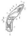
図1及び図2に示すように、本実施形態の薬液投与装置は、薬液を投与する主流路120から分岐して設けられ、薬液の急速投与を行う急速投与部110を備えている。急速投与部110は、主流路120に設けられた流量制御部121よりも基端側において主流路120と接続された流入流路111と、流量制御部121よりも先端側において主流路120と接続された流出流路112と、急速投与部本体115とを有している。 As shown in FIGS. 1 and 2, the drug solution administration device of the present embodiment is provided as a branch from the
急速投与部本体115は流入流路111と流出流路112との間に接続され、薬液を貯留する薬液貯留部113と、薬液貯留部113への薬液の貯留及び薬液貯留部113からの薬液の送出を制御する制御部114とを有している。流入流路111は、第1の流路111Aと、第1の流路111Aよりも流路断面積が小さい第2の流路111Bとを有し、制御部114は、第1の流路111Aを閉止する第1の閉止部141と、流出流路112を開閉可能に閉止する第2の閉止部142とを有している。 The rapid administration section
薬液貯留部113は、押圧により変形させることができ、且つ形状復元力を有する容器とすることができる。例えば、ポリエチレン、ポリプロピレン若しくはポリエステル等の可撓性樹脂、ポリイソプレン若しくはシリコーンゴム等のゴム弾性材料により形成された袋状の容器とすることができる。薬液貯留部113は、1回の急速投与により投与する薬液を貯留できればよく、例えば0.5ml程度〜10ml程度の容量とすることができる。 The
流入流路111及び流出流路112は、可撓性のチューブとすることができ、例えば、ポリ塩化ビニル、ポリエステル、ポリアミド、ポリウレタン、ポリアクリレート、ポリメタクリレート又はポリカーボネート等からなるチューブとすることができる。 The
流入流路111は、第1の流路111Aと第2の流路111Bとに分岐した部分を有している。第1の流路111Aは、通常の可撓性チューブであり、急速投与部110を迅速にプライミングする、バイパス経路としての機能を有する。第2の流路111Bは、流路断面積が第1の流路111Aよりも小さいオリフィスチューブであり、薬液貯留部113に流入する薬液の量を制御する流量制御部として機能する。第1の流路111Aを用いることにより、急速投与部110を迅速にプライミングすることができる。一方、第2の流路111Bにより薬液貯留部113に流入する薬液の流量を調整することができ、薬液貯留部113に薬液が貯留されるまでの時間を調整することができる。これにより、急速投与を禁止するロックアウトタイムを設定することができる。 The
第2の流路111Bは、薬液貯留部113に流入する薬液の流量を調整できるように管路抵抗が設定されている。管路抵抗は、内径及び長さを変化させることにより設定できる。第2の流路111Bの内径及び長さは目的とする流量に応じて決定すればよいが、薬液中の空気が管内壁に付着することによる薬液の流れの停止を抑える観点から、内径は10μm程度以上とすることが好ましく、50μm程度以上とすることがより好ましい。流量の制御性の観点から、内径は500μm程度以下とすることが好ましく、300μm以下とすることがより好ましい。流量の制御性の観点から、長さは1cm以上とすることが好ましい。また、流量の制御性の観点から、第2の流路111Bは変形しにくいことが好ましく、外径が内径の5倍〜500倍程度であるものが好ましい。 In the
上記のような構成の本実施形態の急速投与部110は、第1の閉止部141及び第2の閉止部142を開放した状態として、急速投与部110を薬液で満たすプライミングモードと、第1の閉止部141及び第2の閉止部142を閉止した状態として、薬液貯留部113へ薬液を貯留する薬液貯留モードと、第1の閉止部141を閉止した状態を維持し且つ第2の閉止部142を開放した状態として、薬液貯留部113に貯留された薬液を送出する急速投与モードとを有している。プライミングモードから薬液貯留モードへの移行と、薬液貯留モードと急速投与モードとの間の移行とは、第1の操作ボタン143及び第2の操作ボタン144を有する制御部114により制御することができる。 The
以下に、制御部114を含む急速投与部本体115の具体例を示す。図3〜図5に示すように、本実施形態の急速投与部本体115は、ハウジング116内に収容された、薬液貯留部113と、薬液貯留部113への薬液の流入及び薬液貯留部113からの薬液の送出を制御する制御部114とを有している。制御部114は、ハウジング116の外側から操作できる第1の操作ボタン143及び第2の操作ボタン144と、第1の操作ボタン143及び第2の操作ボタン144により操作される第1の閉止部141及び第2の閉止部142を有している。本実施形態の急速投与部本体115は、どのような向きに配置しても使用することができるが、以下においては、第1の操作ボタン143及び第2の操作ボタン144が設けられた側を上側にしている状態について説明する。 Hereinafter, a specific example of the rapid administration unit
本実施形態において、第1の閉止部141は、第1の操作ボタン143と一体に形成された板状の押圧部である。図5に示すように、第1の操作ボタン143を押圧して押圧部を押し下げると、押圧部が第1の流路111A側に移動して、第1の流路111Aである可撓性チューブを押しつぶして閉止することができる。第1の操作ボタン143は、一旦操作されると第1の閉止部141である押圧部が第1の流路111Aを押しつぶす位置においてロックされる。 In the present embodiment, the
第2の閉止部142は、第2の操作ボタン144と一体に形成され、流出流路112である可撓性チューブを押しつぶして閉止することができる押圧部である。本実施形態において、第2の操作ボタン144は、アーム状部144Bと、アーム状部144Bの第1の端部に設けられたボタン本体144Aとを有し、第2の端部が第2の閉止部142である押圧部となっている。アーム状部144Bの中央部は、ばね147により支持されており、第1の端部に設けられたボタン本体144Aを押し下げると、第2の端部に設けられた第2の閉止部142は、持ち上げられる。また、第1の端部は、薬液貯留部113の上側に配置されており、ボタン本体144Aを押し下げると、薬液貯留部113が押圧される。 The
第2の操作ボタン144は、第2の端部側において第1の操作ボタン143と係合している。具体的には、アーム状部114Bに設けられた開口部144aに、第1の操作ボタン143に設けられた係合突起143aが挿入されている。このため、図5に示すように、第1の操作ボタン143を押し下げてロックすると、第2の端部に設けられた第2の閉止部142である押圧部も、流出流路112側に移動し、流出流路112を閉止する。同時にアーム状部114Bの第1の端部に設けられたボタン本体144Aは、上方に持ち上げられ、操作が可能となる。第1の操作ボタン143がロックされた状態で、ボタン本体144Aを押圧すると、てこの原理により第2の端部に設けられた第2の閉止部142が持ち上がり、流出流路112が開放される。同時に、薬液貯留部113が押圧されるため、薬液貯留部113に貯留された薬液が流出流路112から主流路120へ送出される。流入流路111側はオリフィス管となっているため、流出流路112側と比べて管路抵抗が高く、薬液貯留部113から送出された薬液はほとんどが流出流路112側に流れる。このため、流入流路111側に逆止弁を設けなくてよい。但し、流入流路111側に逆止弁を設けることもできる。 The
本実施形態において、第2の操作ボタン144のアーム状部144Bは、ばね147により支えられている。このため、ボタン本体144Aの押圧を止めると、第2の操作ボタン144は、ばね147の弾発力により自動的に復帰し、薬液貯留部113は押圧されていない状態に戻る。また、第2の閉止部142である押圧部は再び流出流路112側に移動し、流出流路112を閉止する。これにより、薬液貯留部113への薬液の貯留が再開される。 In the present embodiment, the arm-shaped
以上のように、第1のボタン143は、操作されることによりプライミングモードから薬液貯留モードへの移行を行わせ、一度操作されるとロックされる。また、第2の操作ボタン144は、操作されることにより薬液貯留モードから急速投与モードへの移行を行わせる。第2の操作ボタン144は、薬液貯留部113に貯留された薬液を送出した後、自動的に復帰して急速投与モードから薬液貯留モードへの移行を行わせる。 As described above, the
薬液貯留部113に薬液が貯留されていない状態で、第2の操作ボタン144を押圧した場合は、第2の閉止部142が開放されるが、押し出される薬液がないため、急速投与は実施されない。このため、薬液貯留部113に流れ込む薬液の流量を制御し、薬液貯留部113に薬液が貯留されるまでの時間を制御することにより、急速投与の繰り返し使用を禁止するロックアウトタイムを設けることができる。なお、薬液貯留部113が所定の大きさに膨張することにより外れるロック機構等を設け、薬液貯留部113に十分に薬液が貯留されるまで第2の操作ボタン144が操作できないようにすることもできる。 If the
主流路120は、薬液の貯留及び送出を行うポンプ部122と、主流路を流れる薬液の流量を制御する流量制御部121とを有している。ポンプ部122は、バルーンハウジング151内に収容されたバルーン152を有するバルーンポンプである。バルーン152は薬液流入部153から薬液を流入させて加圧状態で貯留することができると共に、薬液流出部155から薬液を流出させることができる。バルーン152の内圧は、必要とする流量等に応じて設定すればよいが、例えば20KPa〜100KPa程度とすることができる。バルーン152は、伸縮性が大きく必要とする内圧を発生させることができればどのような材料により形成してもよく、例えば天然ゴム、合成ゴム又はエラストマー等により形成することができる。 The
流量制御部121は、ポンプ部122から送出され、主流路120内を流れる薬液の流量を制御できる。流量制御部121は、主流路120内を流れる薬液の流量を制御できれば、どのような構成としてもよいが、例えばオリフィスチューブにより形成することができる。オリフィスチューブの内径及び長さは目的とする流量に応じて決定すればよいが、薬液中の空気が管内壁に付着することによる薬液の流れの停止を抑える観点から、内径は10μm程度以上とすることが好ましく、50μm程度以上とすることがより好ましい。流量の制御性の観点から、内径は500μm程度以下とすることが好ましく、300μm以下とすることがより好ましい。流量の制御性の観点から、長さは1cm以上とすることが好ましい。また、流量の制御性の観点から、オリフィスチューブは変形しにくいことが好ましく、外径が内径の5倍〜500倍程度であるものが好ましい。 The flow
流量制御部121の基端側は、チューブ123を介して薬液流出部155と接続されている。流量制御部121の先端側は、チューブ124を介してコネクタ125と接続されている。コネクタ125は、例えば患者の血管内に挿入されたカテーテル等と接続できる。薬液流出部155と流量制御部121の基端側との間には、急速投与部110の流入流路111を分岐させる分岐コネクタ126が設けられている。流量制御部121の先端側とコネクタ125との間には、急速投与部110の流出流路112を合流させる分岐コネクタ127が設けられている。 The base end side of the flow
分岐コネクタ126と薬液流出部155との間にはフィルタ128が設けられている。この位置にフィルタ128を設けることにより、主流路120に設けられた流量制御部121及び急速投与部110に設けられた第2の流路111Bにおいて、異物等による詰まりを発生しにくくすることができる。また、本実施形態においては、急速投与部110に外部から薬液が注入されることがないため、急速投与部110の流出流路112よりも先端側にフィルタを設けなくてよい。これにより部品点数を削減できると共に、流出流路112の流路抵抗の上昇を抑えることができ、急速投与部110の操作性が向上する。但し、流出流路112よりも先端側にフィルタを設けることもできる。 A
以下に、本実施形態の薬液投与装置のプライミング方法を説明する。まず、薬液流入部153から薬液をバルーン152内に注入する。この際に流量制御部121の基端側と、急速投与部110の流入流路111とはクランプにより閉止した状態とすることができる。流量制御部121の基端側のクランプを開放すると、バルーン152の収縮力によりバルーン152内の薬液は薬液流出部155から送出され、主流路120がプライミングされる。 The priming method of the drug solution administration device of the present embodiment will be described below. First, the chemical solution is injected into the
コネクタ125から薬液が流出したことを確認した後、流量制御部121の基端側のクランプを閉じ、流入流路111のクランプを開放する。この状態において、急速投与部110は、第1の閉止部141及び第2の閉止部142が開放されたプライミングモードになっている。従って、管路抵抗が小さい第1の流路111Aを薬液が通ることができ、流量を確保することができる。薬液貯留部113が薬液で満たされると、薬液は流出流路112を通って、先端側のコネクタ125からオーバーフローする。オーバーフローを確認した後、急速投与部110の第1の操作ボタン143を操作し、第1の閉止部141及び第2の閉止部142を閉止する。これにより、主流路120及び急速投与部110のプライミングが完了し、急速投与部110は薬液貯留モードに移行する。このように、本実施形態の急速投与部は、流入流路111にプライミングポートを設けなくても、迅速にプライミングを行うことができる。しかし、緊急用等として、流入流路111にプライミングポートを設けることもできる。 After confirming that the chemical solution has flowed out from the
なお、主流路120を先にプライミングした後、急速投与部110をプライミングする例を示したが、急速投与部110を先にプライミングした後、主流路120をプライミングすることもできる。 Although the example of priming the
プライミングが終了した薬液投与装置のコネクタ125を患者の血管内に挿入されたカテーテル等に接続すれば、バルーン152の収縮力により、バルーン152内の薬液が患者の血管内に持続的に投与される。この場合の投与量は、流量制御部121によって設定された値となる。投与量を一時的に大きくしたい場合には、急速投与部110の第2の操作ボタン144を押し込む。これにより、第2の閉止部142が開放されると共に、薬液貯留部113が押圧され、薬液貯留モードから急速投与モードに移行する。薬液貯留部113内の薬液は、流出流路112を通って主流路120へ送出され、患者に投与される。急速投与を行った後、第2の操作ボタン144から指を離すと、第2の操作ボタン144は自動的に復帰し、急速投与部110は急速投与モードから薬液貯留モードへ移行する。急速投与モードから薬液貯留モードに移行した後、薬液貯留部113に再び薬液が貯留されるまでには所定の時間を要する。この時間は、第2の流路111Bにより設定される流量により決定される。また、第1の操作ボタン143は、一旦操作されるとロックされるため、バイパスである第1の流路111Aを開放できず、急速投与の過剰な使用を防ぐ安全機構として機能する。 When the
薬液投与装置は、体内に薬液を投与するため、流路内を滅菌する。滅菌には一般的にエチレンオキサイトガス(EOG)滅菌、電子線滅菌又はγ線滅菌等が用いられる。EOG滅菌を効率良く行うためには、流路が開放され、流路内をガスが十分に流通することが好ましい。本実施形態の薬液投与装置は、流路内に流路を塞ぐ逆止弁等が設けられていない構成とすることができる。このような構成とすることにより、EOG滅菌が容易にできるという利点が得られる。 The drug solution administration device sterilizes the inside of the flow path in order to administer the drug solution into the body. Ethylene oxide gas (EOG) sterilization, electron beam sterilization, γ-ray sterilization, or the like is generally used for sterilization. In order to efficiently perform EOG sterilization, it is preferable that the flow path is opened and the gas sufficiently flows through the flow path. The chemical solution administration device of the present embodiment may have a configuration in which a check valve or the like that blocks the flow path is not provided in the flow path. With such a configuration, there is an advantage that EOG sterilization can be easily performed.
本実施形態は、ポンプをバルーンの収縮力を用いたバルーンポンプとした例を示した。しかし、所定の圧力で薬液を送出できればどのようなポンプを用いてもよい。例えば、ガス圧を用いるポンプ等を用いることもできる。 In this embodiment, an example is shown in which the pump is a balloon pump using the contraction force of a balloon. However, any pump may be used as long as the chemical solution can be delivered at a predetermined pressure. For example, a pump that uses gas pressure or the like can also be used.
本実施形態において、流量制御部121及び第2の流路111Bには、オリフィスチューブを用いた。しかし、管路抵抗により所定の流量を実現できれば、他の構成とすることもできる。例えば、オリフィスチューブの代わりに逆止弁を設けることもできる。 In this embodiment, an orifice tube is used for the flow
本実施形態において示した急速投与部本体115の構成は一例であり、第1の閉止部141及び第2の閉止部142が所定の動作を行うようにできれば他の構成とすることができる。例えば、図6及び図7に示すようにボタン本体144Aとバルーン113との間にばね148を設けることもできる。これにより、ボタン本体144Aを押圧する指を離した後にボタン144Aが押圧されていない位置に戻りやすくなり、第2の操作ボタン144と一体に形成された第2の閉止部142が、流出流路112である可撓性チューブを押しつぶして閉止する位置に戻りやすくなる。なお、図6及び図7にはバネ148が円錐ばねである例を示したが、ボタン144Aが押圧されていない位置に戻りやすくなればよく、他の構成とすることもできる。 The configuration of the rapid administration unit
本実施形態の薬液投与装置は、PCAに利用することができる。他にも、ヘパリン、化学麻酔、又は抗癌剤の投与等に利用することができる。 The drug solution administration device of the present embodiment can be used for PCA. In addition, it can be used for administration of heparin, chemical anesthesia, anticancer drug, and the like.
本開示の薬液投与装置は、急速投与を禁止するロックアウトタイムの設定が可能で且つプライミングが容易であり、PCA等に用いることができる薬液投与装置として有用である。 The drug solution administration device of the present disclosure is useful as a drug solution administration device that can be used for PCA and the like because a lockout time for prohibiting rapid administration can be set and priming is easy.
110 急速投与部
111 流入流路
111A 第1の流路
111B 第2の流路
112 流出流路
113 薬液貯留部
114 制御部
115 急速投与部本体
116 ハウジング
120 主流路
121 流量制御部
122 ポンプ部
123 チューブ
124 チューブ
125 コネクタ
126 分岐コネクタ
127 分岐コネクタ
128 フィルタ
141 第1の閉止部
142 第2の閉止部
143 第1の操作ボタン
143a 係合突起
144 第2の操作ボタン
144A ボタン本体
144B アーム状部
144a 開口部
147 ばね
148 ばね
151 バルーンハウジング
152 バルーン
153 薬液流入部
155 薬液流出部110
Claims (3)
Translated fromJapanese前記流量制御部の基端側において前記主流路と接続される流入流路と、
前記流量制御部の先端側において前記主流路と接続される流出流路と、
前記流入流路と前記流出流路との間に接続され、薬液を貯留する薬液貯留部と、
前記薬液貯留部への薬液の貯留及び前記薬液貯留部からの薬液の送出を制御する制御部とを備え、
前記流入流路は、第1の流路と前記第1の流路よりも流路断面積が小さい第2の流路とに分岐した部分を有し、
前記制御部は、前記第1の流路を閉止可能な第1の閉止部と、前記第1の閉止部が開放状態から閉止状態となるのに連動して前記流出流路を閉止された状態とし、且つ、前記第1の流路が閉止された状態で、前記流出流路を開閉可能である第2の閉止部とを有する、薬液投与装置の急速投与部。It is a rapid administration unit that performs rapid administration of the drug solution by bypassing the flow rate control unit that controls the flow rate of the main flow path through which the drug solution flows from the proximal end side to the distal end side.
An inlet passage connected tosaid main flow path at the base end side ofthe flow control unit,
An outflow flow path connected to the main flow path on the tip side of the flow rate control unit,
A drug solution storage unit that is connected between the inflow channel and the outflow channel and stores the drug solution,
A control unit for controlling the storage of the drug solution in the drug solution storage unit and the delivery of the drug solution from the drug solution storage unit is provided.
The inflow flow path has a portion branched into a first flow path and a second flow path having a flow path cross-sectional area smaller than that of the first flow path.
The control unit is in a state in which the outflow flow path is closed in conjunction with the first closing portion capable of closing the first flow path and the first closing portion changingfrom the open state to the closed state.and then, and, in a state in which the first flow path is closed, and a second closure can be opened and closed the outlet channel, rapid administration of the drug solution administration device.
前記制御部は、前記プライミングモードから前記薬液貯留モードへの移行と、前記薬液貯留モードと前記急速投与モードとの間の移行とを制御する、請求項1に記載の急速投与部。The rapid administration section has a priming mode in which the rapid administration section is filled with a drug solution, with the first closing section and the second closing section open, and the first closing section and the second closing section. The drug solution storage mode in which the drug solution is stored in the drug solution storage section and the state in which the first closing section is closed and the second closing section is opened are set as the closed state. It has a rapid administration mode that sends out the drug solution stored in the department.
The rapid administration unit according to claim 1, wherein the control unit controls the transition from the priming mode to the drug solution storage mode and the transition between the drug solution storage mode and the rapid administration mode.
操作されることにより前記プライミングモードから前記薬液貯留モードへの移行を行わせ、一度操作されるとロックされる第1の操作ボタンと、
操作されることにより前記薬液貯留モードから前記急速投与モードへの移行を行わせる第2の操作ボタンとを有し、
前記第2の操作ボタンは、前記薬液貯留部に貯留された薬液を送出した後、自動的に復帰して前記急速投与モードから前記薬液貯留モードへの移行を行わせる、請求項2に記載の急速投与部。
The control unit
A first operation button that shifts from the priming mode to the chemical storage mode by being operated and is locked once operated, and
It has a second operation button for shifting from the drug solution storage mode to the rapid administration mode by being operated.
The second operation button according to claim 2, wherein after sending out the drug solution stored in the drug solution storage unit, the second operation button automatically returns to perform the transition from the rapid administration mode to the drug solution storage mode. Rapid administration department.
Applications Claiming Priority (3)
| Application Number | Priority Date | Filing Date | Title |
|---|---|---|---|
| JP2015240691 | 2015-12-10 | ||
| JP2015240691 | 2015-12-10 | ||
| JP2017554774AJP6724929B2 (en) | 2015-12-10 | 2016-10-31 | Chemical dosing device |
Related Parent Applications (1)
| Application Number | Title | Priority Date | Filing Date |
|---|---|---|---|
| JP2017554774ADivisionJP6724929B2 (en) | 2015-12-10 | 2016-10-31 | Chemical dosing device |
Publications (2)
| Publication Number | Publication Date |
|---|---|
| JP2020163204A JP2020163204A (en) | 2020-10-08 |
| JP6935830B2true JP6935830B2 (en) | 2021-09-15 |
Family
ID=59012857
Family Applications (2)
| Application Number | Title | Priority Date | Filing Date |
|---|---|---|---|
| JP2017554774AActiveJP6724929B2 (en) | 2015-12-10 | 2016-10-31 | Chemical dosing device |
| JP2020108929AActiveJP6935830B2 (en) | 2015-12-10 | 2020-06-24 | Rapid administration |
Family Applications Before (1)
| Application Number | Title | Priority Date | Filing Date |
|---|---|---|---|
| JP2017554774AActiveJP6724929B2 (en) | 2015-12-10 | 2016-10-31 | Chemical dosing device |
Country Status (6)
| Country | Link |
|---|---|
| EP (2) | EP3669909B1 (en) |
| JP (2) | JP6724929B2 (en) |
| CN (1) | CN108289999B (en) |
| AU (2) | AU2016365938B2 (en) |
| ES (1) | ES2964749T3 (en) |
| WO (1) | WO2017098685A1 (en) |
Families Citing this family (7)
| Publication number | Priority date | Publication date | Assignee | Title |
|---|---|---|---|---|
| AU2017422386A1 (en)* | 2017-07-06 | 2020-01-23 | Avent, Inc. | Priming system for infusion devices |
| JP7187908B2 (en)* | 2018-09-13 | 2022-12-13 | ニプロ株式会社 | Chemical solution administration device and chemical injection controller used for the chemical solution administration device |
| WO2021015281A1 (en) | 2019-07-22 | 2021-01-28 | ニプロ株式会社 | Drug solution injection controller |
| JP2021020002A (en)* | 2019-07-30 | 2021-02-18 | 大研医器株式会社 | Liquid medicine injection device and liquid medicine injection system |
| KR102373991B1 (en)* | 2019-10-18 | 2022-03-15 | 김용현 | Medicinal liquid injection apparatus and preparing method for medicinal liquid injection |
| JP7427779B2 (en)* | 2019-11-01 | 2024-02-05 | ヨンヒョン キム | Chemical liquid push device and chemical liquid injection device including the same |
| KR102196122B1 (en)* | 2019-12-06 | 2020-12-29 | 주식회사 유니메딕스 | Patient controlled drug administration device |
Family Cites Families (13)
| Publication number | Priority date | Publication date | Assignee | Title |
|---|---|---|---|---|
| AUPM838294A0 (en)* | 1994-09-26 | 1994-10-20 | Belser, G.F. | Auto refill not vented to atmosphere vented burette |
| CA2185346C (en)* | 1995-06-06 | 2005-11-29 | Osamu Tsukada | Portable analgesic system |
| JPH1099432A (en) | 1996-09-26 | 1998-04-21 | Jms Co Ltd | Chemical self-filling unit and device for self-filling chemical |
| US5785681A (en)* | 1997-02-25 | 1998-07-28 | Minimed Inc. | Flow rate controller for a medication infusion pump |
| JPH10295812A (en)* | 1997-05-01 | 1998-11-10 | Terumo Corp | Medical liquid supply tool |
| JP3073979B1 (en)* | 1999-03-15 | 2000-08-07 | 大研医器株式会社 | Chemical injection device |
| JP4010005B2 (en)* | 2000-02-29 | 2007-11-21 | ニプロ株式会社 | Device for adjusting injection speed of chemical injector |
| CN2438457Y (en)* | 2000-07-20 | 2001-07-11 | 珠海福尼亚医疗设备有限公司 | Quantity self-controller for disposable micro-pain-relieving pump |
| CN1496744A (en)* | 2002-10-18 | 2004-05-19 | 尼普洛株式会社 | Soup syringe |
| KR100919651B1 (en)* | 2004-03-12 | 2009-09-30 | 니프로 가부시키가이샤 | Pca device which is capable of persistently infusing and additionally administrating drug |
| AU2005306461B2 (en)* | 2004-11-19 | 2011-01-20 | Curlin Medical Inc. | Controlled-volume infusion device |
| JP6222562B2 (en)* | 2013-12-24 | 2017-11-01 | オーベクス株式会社 | Chemical liquid injection device and chemical liquid injection system including the same |
| CN204637206U (en)* | 2015-04-23 | 2015-09-16 | 周云康 | A kind of assisted breathing system with expectoration function |
- 2016
- 2016-10-31EPEP20157248.4Apatent/EP3669909B1/enactiveActive
- 2016-10-31WOPCT/JP2016/004773patent/WO2017098685A1/ennot_activeCeased
- 2016-10-31AUAU2016365938Apatent/AU2016365938B2/enactiveActive
- 2016-10-31JPJP2017554774Apatent/JP6724929B2/enactiveActive
- 2016-10-31CNCN201680071337.9Apatent/CN108289999B/enactiveActive
- 2016-10-31ESES20157248Tpatent/ES2964749T3/enactiveActive
- 2016-10-31EPEP16872587.7Apatent/EP3372262B1/enactiveActive
- 2020
- 2020-06-24JPJP2020108929Apatent/JP6935830B2/enactiveActive
- 2021
- 2021-05-24AUAU2021203345Apatent/AU2021203345B2/enactiveActive
Also Published As
| Publication number | Publication date |
|---|---|
| AU2016365938B2 (en) | 2021-02-25 |
| CN108289999A (en) | 2018-07-17 |
| EP3372262A4 (en) | 2019-01-23 |
| JP6724929B2 (en) | 2020-07-15 |
| ES2964749T3 (en) | 2024-04-09 |
| JPWO2017098685A1 (en) | 2018-09-27 |
| EP3669909B1 (en) | 2023-08-23 |
| EP3669909A1 (en) | 2020-06-24 |
| AU2016365938A1 (en) | 2018-06-21 |
| EP3372262A1 (en) | 2018-09-12 |
| AU2021203345A1 (en) | 2021-06-24 |
| CN108289999B (en) | 2020-12-01 |
| AU2021203345B2 (en) | 2022-10-27 |
| WO2017098685A1 (en) | 2017-06-15 |
| EP3372262B1 (en) | 2020-03-11 |
| JP2020163204A (en) | 2020-10-08 |
Similar Documents
| Publication | Publication Date | Title |
|---|---|---|
| JP6935830B2 (en) | Rapid administration | |
| US5356379A (en) | Disposable ambulatory infusion pump assembly | |
| EP3151907B1 (en) | Tubing assembly | |
| US5188603A (en) | Fluid infusion delivery system | |
| US8814829B2 (en) | Drug delivery device for fluid restricted patients | |
| US20080004574A1 (en) | Selectable rate intravenous infusion set | |
| US20130123703A1 (en) | Pulse infusion device system and method | |
| US20210369981A1 (en) | Drug delivery device with air and backflow elimination | |
| JP6945661B2 (en) | Priming system for injection equipment | |
| EP3436112B1 (en) | Pulse infusion device system and method | |
| US20230321337A1 (en) | Delivery system and method for the effective, reliable and foolproof delivery of controlled amounts of a medical fluid | |
| US10279129B2 (en) | Pulse infusion device system and method | |
| JP4539382B2 (en) | Patient controlled analgesia (PCA) device with continuous infusion and additional administration | |
| US20170143894A1 (en) | Inline patency check device | |
| WO2023117771A1 (en) | Fluid delivery system | |
| JP4933562B2 (en) | Flow control device including valve and flow control unit | |
| EP3283144B1 (en) | Pulse infusion device | |
| KR102854651B1 (en) | Chemical Liquid Infusion Device Conroled Supply | |
| US11712510B2 (en) | Delivery system and method for the effective, reliable and foolproof delivery of controlled amounts of a medical fluid | |
| JP7213528B2 (en) | pressurized drug injector | |
| WO2025166468A1 (en) | System and method for intraveous administration of fluids and/or medication | |
| JP3185454U (en) | Chemical injection device | |
| HK40061587A (en) | Liquid medicine self-injection system |
Legal Events
| Date | Code | Title | Description |
|---|---|---|---|
| A621 | Written request for application examination | Free format text:JAPANESE INTERMEDIATE CODE: A621 Effective date:20200624 | |
| A131 | Notification of reasons for refusal | Free format text:JAPANESE INTERMEDIATE CODE: A131 Effective date:20210427 | |
| A521 | Request for written amendment filed | Free format text:JAPANESE INTERMEDIATE CODE: A523 Effective date:20210625 | |
| TRDD | Decision of grant or rejection written | ||
| A01 | Written decision to grant a patent or to grant a registration (utility model) | Free format text:JAPANESE INTERMEDIATE CODE: A01 Effective date:20210727 | |
| A61 | First payment of annual fees (during grant procedure) | Free format text:JAPANESE INTERMEDIATE CODE: A61 Effective date:20210809 | |
| R150 | Certificate of patent or registration of utility model | Ref document number:6935830 Country of ref document:JP Free format text:JAPANESE INTERMEDIATE CODE: R150 |