JP6933045B2 - Object detection device, sensing device, mobile device and object detection method - Google Patents
Object detection device, sensing device, mobile device and object detection methodDownload PDFInfo
- Publication number
- JP6933045B2 JP6933045B2JP2017157859AJP2017157859AJP6933045B2JP 6933045 B2JP6933045 B2JP 6933045B2JP 2017157859 AJP2017157859 AJP 2017157859AJP 2017157859 AJP2017157859 AJP 2017157859AJP 6933045 B2JP6933045 B2JP 6933045B2
- Authority
- JP
- Japan
- Prior art keywords
- light
- object detection
- signal
- detection device
- vth
- Prior art date
- Legal status (The legal status is an assumption and is not a legal conclusion. Google has not performed a legal analysis and makes no representation as to the accuracy of the status listed.)
- Active
Links
Images


Classifications
- G—PHYSICS
- G01—MEASURING; TESTING
- G01S—RADIO DIRECTION-FINDING; RADIO NAVIGATION; DETERMINING DISTANCE OR VELOCITY BY USE OF RADIO WAVES; LOCATING OR PRESENCE-DETECTING BY USE OF THE REFLECTION OR RERADIATION OF RADIO WAVES; ANALOGOUS ARRANGEMENTS USING OTHER WAVES
- G01S17/00—Systems using the reflection or reradiation of electromagnetic waves other than radio waves, e.g. lidar systems
- G01S17/02—Systems using the reflection of electromagnetic waves other than radio waves
- G01S17/04—Systems determining the presence of a target
- G—PHYSICS
- G01—MEASURING; TESTING
- G01S—RADIO DIRECTION-FINDING; RADIO NAVIGATION; DETERMINING DISTANCE OR VELOCITY BY USE OF RADIO WAVES; LOCATING OR PRESENCE-DETECTING BY USE OF THE REFLECTION OR RERADIATION OF RADIO WAVES; ANALOGOUS ARRANGEMENTS USING OTHER WAVES
- G01S17/00—Systems using the reflection or reradiation of electromagnetic waves other than radio waves, e.g. lidar systems
- G01S17/02—Systems using the reflection of electromagnetic waves other than radio waves
- G01S17/06—Systems determining position data of a target
- G01S17/42—Simultaneous measurement of distance and other co-ordinates
- G—PHYSICS
- G01—MEASURING; TESTING
- G01S—RADIO DIRECTION-FINDING; RADIO NAVIGATION; DETERMINING DISTANCE OR VELOCITY BY USE OF RADIO WAVES; LOCATING OR PRESENCE-DETECTING BY USE OF THE REFLECTION OR RERADIATION OF RADIO WAVES; ANALOGOUS ARRANGEMENTS USING OTHER WAVES
- G01S7/00—Details of systems according to groups G01S13/00, G01S15/00, G01S17/00
- G01S7/48—Details of systems according to groups G01S13/00, G01S15/00, G01S17/00 of systems according to group G01S17/00
- G01S7/483—Details of pulse systems
- G01S7/484—Transmitters
- G—PHYSICS
- G01—MEASURING; TESTING
- G01S—RADIO DIRECTION-FINDING; RADIO NAVIGATION; DETERMINING DISTANCE OR VELOCITY BY USE OF RADIO WAVES; LOCATING OR PRESENCE-DETECTING BY USE OF THE REFLECTION OR RERADIATION OF RADIO WAVES; ANALOGOUS ARRANGEMENTS USING OTHER WAVES
- G01S7/00—Details of systems according to groups G01S13/00, G01S15/00, G01S17/00
- G01S7/48—Details of systems according to groups G01S13/00, G01S15/00, G01S17/00 of systems according to group G01S17/00
- G01S7/483—Details of pulse systems
- G01S7/486—Receivers
- G01S7/487—Extracting wanted echo signals, e.g. pulse detection
- G—PHYSICS
- G01—MEASURING; TESTING
- G01C—MEASURING DISTANCES, LEVELS OR BEARINGS; SURVEYING; NAVIGATION; GYROSCOPIC INSTRUMENTS; PHOTOGRAMMETRY OR VIDEOGRAMMETRY
- G01C3/00—Measuring distances in line of sight; Optical rangefinders
- G01C3/02—Details
- G01C3/06—Use of electric means to obtain final indication
- G01C3/08—Use of electric radiation detectors
- G—PHYSICS
- G01—MEASURING; TESTING
- G01S—RADIO DIRECTION-FINDING; RADIO NAVIGATION; DETERMINING DISTANCE OR VELOCITY BY USE OF RADIO WAVES; LOCATING OR PRESENCE-DETECTING BY USE OF THE REFLECTION OR RERADIATION OF RADIO WAVES; ANALOGOUS ARRANGEMENTS USING OTHER WAVES
- G01S17/00—Systems using the reflection or reradiation of electromagnetic waves other than radio waves, e.g. lidar systems
- G01S17/02—Systems using the reflection of electromagnetic waves other than radio waves
- G01S17/06—Systems determining position data of a target
- G01S17/08—Systems determining position data of a target for measuring distance only
- G01S17/10—Systems determining position data of a target for measuring distance only using transmission of interrupted, pulse-modulated waves
- G—PHYSICS
- G01—MEASURING; TESTING
- G01S—RADIO DIRECTION-FINDING; RADIO NAVIGATION; DETERMINING DISTANCE OR VELOCITY BY USE OF RADIO WAVES; LOCATING OR PRESENCE-DETECTING BY USE OF THE REFLECTION OR RERADIATION OF RADIO WAVES; ANALOGOUS ARRANGEMENTS USING OTHER WAVES
- G01S17/00—Systems using the reflection or reradiation of electromagnetic waves other than radio waves, e.g. lidar systems
- G01S17/88—Lidar systems specially adapted for specific applications
- G01S17/93—Lidar systems specially adapted for specific applications for anti-collision purposes
- G01S17/931—Lidar systems specially adapted for specific applications for anti-collision purposes of land vehicles
- G—PHYSICS
- G01—MEASURING; TESTING
- G01S—RADIO DIRECTION-FINDING; RADIO NAVIGATION; DETERMINING DISTANCE OR VELOCITY BY USE OF RADIO WAVES; LOCATING OR PRESENCE-DETECTING BY USE OF THE REFLECTION OR RERADIATION OF RADIO WAVES; ANALOGOUS ARRANGEMENTS USING OTHER WAVES
- G01S7/00—Details of systems according to groups G01S13/00, G01S15/00, G01S17/00
- G01S7/48—Details of systems according to groups G01S13/00, G01S15/00, G01S17/00 of systems according to group G01S17/00
- G01S7/483—Details of pulse systems
- G01S7/486—Receivers
- G01S7/4868—Controlling received signal intensity or exposure of sensor
- G—PHYSICS
- G02—OPTICS
- G02B—OPTICAL ELEMENTS, SYSTEMS OR APPARATUS
- G02B26/00—Optical devices or arrangements for the control of light using movable or deformable optical elements
- G02B26/08—Optical devices or arrangements for the control of light using movable or deformable optical elements for controlling the direction of light
- G02B26/10—Scanning systems
- G02B26/105—Scanning systems with one or more pivoting mirrors or galvano-mirrors
- G—PHYSICS
- G02—OPTICS
- G02B—OPTICAL ELEMENTS, SYSTEMS OR APPARATUS
- G02B27/00—Optical systems or apparatus not provided for by any of the groups G02B1/00 - G02B26/00, G02B30/00
- G02B27/0025—Optical systems or apparatus not provided for by any of the groups G02B1/00 - G02B26/00, G02B30/00 for optical correction, e.g. distorsion, aberration
- G02B27/0031—Optical systems or apparatus not provided for by any of the groups G02B1/00 - G02B26/00, G02B30/00 for optical correction, e.g. distorsion, aberration for scanning purposes
Landscapes
- Physics & Mathematics (AREA)
- Engineering & Computer Science (AREA)
- Electromagnetism (AREA)
- Computer Networks & Wireless Communication (AREA)
- General Physics & Mathematics (AREA)
- Radar, Positioning & Navigation (AREA)
- Remote Sensing (AREA)
- Optical Radar Systems And Details Thereof (AREA)
Description
Translated fromJapanese本発明は、物体検出装置、センシング装置、移動体装置及び物体検出方法に関する。 The present invention relates to an object detection device, a sensing device, a moving body device, and an object detection method.
従来、投光し、物体で反射された光を受光して電気信号に変換し、該電気信号を二値化することにより、その物体に関する情報(例えば物体の有無、物体までの距離、物体の形状等)を検出する技術が知られている(例えば特許文献1〜4参照)。 Conventionally, by projecting light, receiving light reflected by an object, converting it into an electric signal, and binarizing the electric signal, information about the object (for example, the presence or absence of the object, the distance to the object, the object's) A technique for detecting a shape (shape, etc.) is known (see, for example,
しかしながら、特許文献1〜4に開示されている技術では、誤検出を抑制することに関して改善の余地があった。 However, in the techniques disclosed in
本発明は、光源からの光を投光し物体で反射された光を受光素子で受光することで物体検出を行う物体検出装置であって、前記受光素子からの信号を閾値Vthで二値化する二値化回路を備え、前記二値化回路で二値化された信号のうちハイレベル信号がM回出力されるまで、同一方向について物体検出動作を行い、Mの値は、前記受光素子におけるピーク強度が閾値Vthを超えるショットノイズの出現確率に基づいて設定されていることを特徴とする物体検出装置である。The present invention is an object detection device that detects an object by projecting light from a light source and receiving the light reflected by the object with a light receiving element, and binarizesa signal from the light receiving element with a threshold value Vth. An object detection operation is performed in the same direction until a high-level signal is output M times among the signals binarized by the binarization circuit, and the value of M is the received light. It is an object detection device characterized in that the peak intensity in the element is set based on the appearance probability of shot noise exceeding thethreshold value Vth.
本発明によれば、誤検出を抑制することができる。 According to the present invention, erroneous detection can be suppressed.
以下に、本発明の一実施形態の物体検出装置100について、図面を参照して説明する。
図1には、物体検出装置100の概略的構成がブロック図にて示されている。Hereinafter, the
FIG. 1 shows a schematic configuration of the
物体検出装置100は、物体(例えば先行車両、停車車両、構造物、歩行者等)の有無や、該物体までの距離等の物体情報を検出するレーザレーダである。レーザレーダは、ライダ(Lidar:Light Detection and Ranging、Laser Imaging Detection and Ranging)とも呼ばれる。物体検出装置100は、一例として、移動体としての車両(例えば自動車)に搭載され、例えば自動車のバッテリ(蓄電池)から電力の供給を受ける。以下では、物体検出装置100として、走査型のレーザレーダについて説明を進めるが、非走査型のレーザレーダとすることも可能である。 The
物体検出装置100は、投光系10、受光光学系30、検出系40、同期系50、時間計測部45、測定制御部46、物体認識部47などを備えている。 The
投光系10は、発光素子としてのLD(レーザダイオード)、LD駆動部12、投光光学系20を含む。 The
LDは、端面発光レーザとも呼ばれ、LD駆動部12(ドライブ回路)により駆動され、レーザ光を射出する。LD駆動部12は、測定制御部46から出力されるLD駆動信号(矩形パルス信号)を用いてLDを点灯(発光)させる。LD駆動部12は、一例として、LDに電流を供給可能に接続されたコンデンサ、該コンデンサとLDとの間の導通/非導通を切り替えるためのトランジスタ、該コンデンサを充電可能な充電手段等を含む。測定制御部46は、自動車のECU(エレクトリックコントロールユニット)からの測定制御信号(測定開始信号や測定停止信号)を受けて測定開始や測定停止を行う。 The LD is also called an end face emitting laser, and is driven by the LD drive unit 12 (drive circuit) to emit laser light. The
図2(A)には、投光光学系20、同期系50が模式的に示されている。図2(B)には、受光光学系30が模式的に示されている。以下では、図2(A)等に示されるZ軸方向を鉛直方向とするXYZ3次元直交座標系を適宜用いて説明する。 FIG. 2A schematically shows the projectile
投光光学系20は、図2(A)に示されるように、LDからの光の光路上に配置されたカップリングレンズ22と、該カップリングレンズ22を介した光の光路上に配置された反射ミラー24と、該反射ミラー24で反射された光の光路上に配置された偏向器としての回転ミラー26と、を含む。ここでは、装置を小型化するために、カップリングレンズ22と回転ミラー26との間の光路上に反射ミラー24を設けて光路を折り返している。 As shown in FIG. 2A, the projection
そこで、LDから出射された光は、カップリングレンズ22により所定のビームプロファイルの光に整形された後、反射ミラー24で反射され、回転ミラー26でZ軸周りに偏向される。 Therefore, the light emitted from the LD is shaped into light having a predetermined beam profile by the
回転ミラー26でZ軸周りの所定の偏向範囲に偏向された光が投光光学系20から投射された光、すなわち物体検出装置100から投光された光である。 The light deflected to a predetermined deflection range around the Z axis by the
回転ミラー26は、回転軸(Z軸)周りに複数の反射面を有し、反射ミラー24からの光を回転軸周りに回転しながら反射(偏向)することで該光により上記偏向範囲に対応する有効走査領域を水平な1軸方向(ここではY軸方向)に1次元走査する。ここでは、偏向範囲、有効走査領域は、物体検出装置100の+X側である。以下では、回転ミラー26の回転方向を「ミラー回転方向」とも呼ぶ。また、本明細書では「有効走査領域」を「投光範囲」や「検出範囲」とも呼ぶ。 The
回転ミラー26は、図2(A)から分かるように、反射面を2面(対向する2つの面)有しているが、これに限らず、1面でも3面以上でも良い。また、少なくとも2つの反射面を設け、回転ミラーの回転軸に対して異なった角度で傾けて配置して、走査・検出する領域をZ軸方向に切り替えることも可能である。 As can be seen from FIG. 2A, the
受光光学系30は、図2(B)に示されるように、投光光学系20から投射され有効走査領域内にある物体で反射(散乱)された光を反射する回転ミラー26と、該回転ミラー26からの光を反射する反射ミラー24と、該反射ミラー24からの光の光路上に配置され、該光を後述する時間計測用PD42に結像させる、少なくとも1つのレンズを含む結像光学系と、を含む。なお、「PD」は、フォトダイオードの略称である。 As shown in FIG. 2B, the light receiving
図2(C)には、LDから反射ミラー24までの光路と、反射ミラー24から時間計測用PD42までの光路が示されている。 FIG. 2C shows an optical path from the LD to the
図2(C)から分かるように、投光光学系20と受光光学系30は、Z軸方向に重なるように配置されており、回転ミラー26と反射ミラー24は、投光光学系20と受光光学系30で共通となっている。これにより、物体上におけるLDの照射範囲と時間計測用PD42の受光可能範囲の相対的な位置ずれを小さくでき、安定した物体検出を実現できる。 As can be seen from FIG. 2C, the light projecting
そこで、投光光学系20から投射され物体で反射(散乱)された光は、回転ミラー26、反射ミラー24を介して結像光学系に導かれ、該結像光学系により時間計測用PD42に集光する(図2(B)参照)。図2(B)では、装置を小型化するために、回転ミラー26と結像光学系との間に反射ミラー24を設けて光路を折り返している。ここでは、結像光学系は2枚のレンズ(結像レンズ)で構成されているが、1枚のレンズとしても良いし、3枚以上のレンズとしても良いし、ミラー光学系を用いても良い。Therefore, the light reflected (scattered) by an object is projected from the light projecting
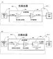
図1に戻り、検出系40は、光検出器43、二値化回路44(コンパレータ)を含む。図3(A)及び図3(B)には、それぞれ光検出器43の構成例である光検出器43−1、43−2が示されている。 Returning to FIG. 1, the
光検出器43は、図3(A)及び図3(B)に示されるように、投光光学系20から投射され有効走査領域内にある物体で反射もしくは散乱された光を、受光光学系30を介して受光する受光素子としての時間計測用PD42(フォトダイオード)と、該時間計測用PD42の出力電流を処理する処理回路と、を含む。 As shown in FIGS. 3 (A) and 3 (B), the
光検出器43の処理回路は、時間計測用PD42からの出力電流(電流値)を電圧信号(電圧値)に変換する電流電圧変換器60a(例えばTIA:トランスインピーダンスアンプ)と、該電流電圧変換器からの電圧信号を増幅する信号増幅器60b(例えばVGA:高リニアリティアナログ可変利得アンプ)とを有する(図3(A)及び図3(B)参照)。処理回路60−2は、信号増幅器60bの後段にハイパスフィルタ(HPF)を有する。 The processing circuit of the
二値化回路44は、光検出器43の処理回路からのアナログの電圧信号(受光信号)を、閾値を基準に二値化し、その二値化信号(デジタル信号)を検出信号として時間計測部45に出力する。 The
同期系50は、図2(A)及び図1に示されるように、LDから出射されカップリングレンズ22を介して反射ミラー24で反射された光であって回転ミラー26で偏向され反射ミラー24で再び反射された光の光路上に配置された結像レンズ52と、該結像レンズ52を介した光の光路上に配置された受光素子としての同期検知用PD54及び該同期検知用PD54の出力電流を処理する処理回路を含む光検出器53と、該光検出器53からの出力電圧を二値化する二値化回路56(コンパレータ)とを含む。 As shown in FIGS. 2A and 1, the
光検出器53の処理回路は、光検出器43の処理回路60−1や処理回路60−2と同様の構成を有している。 The processing circuit of the
反射ミラー24は、上記偏向範囲に対して回転ミラー26の回転方向上流側に配置され、回転ミラー26で上記偏向範囲の上流側に偏向された光が入射される。そして、回転ミラー26で偏向され反射ミラー24で反射された光が結像レンズ52を介して同期検知用PD54に入射される。このとき、光検出器53では、同期検知用PD54からの出力電流が処理回路に送られる。 The
なお、反射ミラー24は、上記偏向範囲に対して回転ミラー26の回転方向下流側に配置されても良い。そして、回転ミラー26で偏向され反射ミラー24で反射された光の光路上に同期系50が配置されても良い。 The
回転ミラー26の回転により、該回転ミラー26の反射面で反射された光が同期検知用PD54で受光される度に同期検知用PD54から電流が出力される。すなわち、同期検知用PD54からは定期的に電流が出力される。 Due to the rotation of the
このように回転ミラー26からの光を同期検知用PD54に照射するための同期点灯を行うことで、同期検知用PD54での受光タイミングから、回転ミラー26の回転タイミングを得ることが可能となる。 By performing synchronous lighting for irradiating the
そこで、LDを同期点灯してから所定時間経過後にLDをパルス点灯することで有効走査領域を光走査することができる。すなわち、同期検知用PD54に光が照射されるタイミングの前後期間にLDをパルス点灯することで有効走査領域を光走査することができる。 Therefore, the effective scanning region can be lightly scanned by lighting the LD in a pulsed manner after a lapse of a predetermined time from the synchronous lighting of the LD. That is, the effective scanning region can be light-scanned by pulse-lighting the LD in the period before and after the timing when the
ここで、時間計測や同期検知に用いる受光素子としては、上述したPD(Photo Diode)の他、APD(Avalanche Photo Diode)、ガイガーモードAPDであるSPAD(Single Photon Avalanche Diode)等を用いることが可能である。APDやSPADは、PDに対して感度が高いため、検出精度や検出距離の点で有利である。 Here, as the light receiving element used for time measurement and synchronization detection, in addition to the PD (Photodiode) described above, an APD (Avalanche Photodiode), a Geiger mode APD SPAD (Single Photodiode Dictionary), or the like can be used. Is. Since APD and SPAD have high sensitivity to PD, they are advantageous in terms of detection accuracy and detection distance.
二値化回路56は、光検出器53の処理回路からのアナログの電圧信号(出力電圧)を、閾値を基準に二値化し、その二値化信号(デジタル信号)を同期信号として測定制御部46に出力する。 The
測定制御部46は、二値化回路56からの同期信号に基づいてLD駆動信号を生成し、該LD駆動信号をLD駆動部12及び時間計測部45に出力する。すなわち、LD駆動信号は、同期信号に対して遅延した発光制御信号(周期的なパルス信号)である。 The
LD駆動信号がLD駆動部12に入力されると、LD駆動部12からLDに駆動電流が印加され、LDから発光パルスが出力される。なお、LDの安全性やLDの耐久性の観点からLDの発光のデューティが制限されるため、発光パルスはパルス幅が狭い方が望ましく、該パルス幅は、一般に10ns〜数10ns程度に設定される。また、パルス間隔は一般に数10μ秒程度である。 When the LD drive signal is input to the
時間計測部45は、測定制御部46からのLD駆動信号と二値化回路44からの検出信号(二値化信号)に基づいて、LDでの発光タイミングと時間計測用PD42での受光タイミングの時間差を求め、該時間差を時間計測結果として測定制御部46に出力する。 The
測定制御部46は、時間計測部45からの時間計測結果を距離に変換することで物体までの往復距離を算出し、該往復距離の1/2を距離データとして物体認識部47に出力する。物体認識部47は、測定制御部46からの1走査もしくは複数の走査で取得した複数の距離データに基づいて、物体の位置や形状や大きさを認識し、その物体認識結果を測定制御部46に出力する。測定制御部46は、該物体認識結果をECUに転送する。 The
ECUは、転送された物体認識結果に基づいて、例えば自動車の操舵制御(例えばオートステアリング)、速度制御(例えばオートブレーキ)等を行う。 The ECU performs, for example, steering control (for example, auto-steering), speed control (for example, auto-brake), or the like of an automobile based on the transferred object recognition result.
以下では、物体検出装置100が走査型である場合のみならず、非走査型である場合も念頭に置いて説明を行う。なお、非走査型の物体検出装置では、例えば発光素子からの光を直接又はレンズを介して投光する。 In the following, the description will be given in consideration of not only the case where the
ところで、閾値を基準に受光信号(光検出器43の出力信号)を検出する方式では、ノイズによる誤検出を防ぐためにノイズに対して閾値Vthを充分高くする必要があるが、高くしすぎると測距可能な最大距離が短くなってしまう。By the way, in the method of detecting the received signal (output signal of the photodetector 43) based on the threshold value,it is necessary to raise the threshold value Vth sufficiently with respect to noise in order to prevent erroneous detection due to noise, but if it is too high, it is necessary. The maximum distance that can be measured becomes shorter.
また、ショットノイズの強度分布は平均=0の正規分布に従うので、Vthをどれだけ高く設定しても、確率論的にピーク強度がVthを超えるショットノイズは存在する。従って、単純にピーク強度がVthを超えた信号を常に物体からの反射光による信号であると判断すると、特にショットノイズの多い環境下では、誤検出を招きやすい。Moreover, since the intensity distribution of shot noise follows a normal distribution with an average of 0, nomatter how high V th is set, there is shot noisewhose peak intensity stochastically exceeds V th. Therefore, if it is simply determined thatthe signal whose peak intensity exceeds Vth is always the signal due to the reflected light from the object, erroneous detection is likely to occur especially in an environment with a lot of shot noise.
そこで、ショットノイズを考慮してVthを設定することが望まれる。ショットノイズの強度を強度分布(図4参照)の標準偏差σsnと定義すると、Vth=σsnのとき、ピーク強度がVthを超えるショットノイズの出現確率は15.87%である。Therefore, it is desirable to setVth in consideration of shot noise. If the intensity of shot noise is defined asthe standard deviation σ sn of the intensity distribution (see FIG. 4), the probability of appearance of shot noise whose peak intensityexceeds V this 15.87% when V th = σsn.
回転ミラー26の任意の角度(任意の投光方向)における測距可能な最大距離を例えば180mとすると、光が物体検出装置100と物体との間を往復する時間は、180×2/(3×108)=1.2μsである。Assuming that the maximum distance that can be measured at an arbitrary angle (arbitrary projection direction) of the
物体検出装置100が二値化回路44から得られる情報は、信号の立ち上がり時刻trと立ち下り時刻tfであるため、物体からの反射光による信号(以下では「物体からの信号」とも呼ぶ)とショットノイズの分離を考える場合、最も難しいのは物体からの信号のパルス幅ωobj=tf−tr(本実施例ではωobj=20ns)と、ショットノイズのパルス幅ωsn=tf−trがほぼ同じとなるケースである。なお、「ωobj」はLD駆動信号のパルス幅と略同一と言って差し支えない。Since the information obtained from the
このような物体からの信号と紛らわしいショットノイズは、180mの中に60(=1.2μs/20ns)個含まれるが、ピーク強度がVthを超えるのは確率論的に60×0.1587=9.5個となる。60 (= 1.2 μs / 20 ns) shot noises that are confusing with the signal from such an object are included in 180 m, but it is probabilistically 60 × 0.1587that the peak intensity exceeds V th. It will be 9.5 pieces.
このことから、回転ミラー26の任意の同一角度で取得された11個の信号を処理回路(60−1や60−2)及び二値化回路44で処理すれば、必ず物体からの信号を検出できる。 From this, if 11 signals acquired at an arbitrary same angle of the
これをもう少し一般化すると、ショットノイズの強度分布は図4に示すような正規分布N(0、σsn)に従っている。この正規分布における横軸(x軸)−∞から任意のx座標までの面積は標準正規累積分布関数F(x、0、σsn)として定義される。従って、x=Vthとすると、ピーク強度がVthを超えるショットノイズの出現確率(図4の網掛け部分)は、1−F(Vth、0、σsn)=F(−Vth、0、σsn)と書ける。先の実施例ではVth=σsnとしたので15.87%であったが、Vth=2σsnならば2.27%、Vth=3σsnならば0.13%である。To generalize this a little more, the intensity distribution of shot noise follows a normal distribution N (0, σsn ) as shown in FIG. The area from the horizontal axis (x-axis) −∞ to any x-coordinate in this normal distribution is defined as thestandard normal cumulative distribution function F (x, 0, σ sn).Therefore, assuming that x = V th, the probability of appearance of shot noise whose peak intensityexceeds V th (shaded portion in FIG. 4) is 1-F (Vth , 0, σsn ) = F (−Vth , It can be written as 0, σsn). In the previous example, since Vth = σsn , it was 15.87%, butif V th = 2σsn, it is 2.27%, and if Vth = 3σsn , it is 0.13%.
ここで、物体検出装置100が測距可能な最大距離をLとしたとき、光が物体検出装置100と物体との間を往復する時間は、光速をcとして、2L/cである。 Here, when the maximum distance that the
また、考慮すべきショットノイズのパルス幅ωsnは物体からの信号のパルス幅ωobj(≒LD駆動信号のパルス幅)と同程度なので、Vthを超えるショットノイズの個数は、
先の例を展開すると、L=180m、ハイパスフィルタのカットオフ周波数fc=25MHzなので、Vth=2σsnならばM=3個、Vth=3σsnならばM=2個である。Expanding the previous example, L = 180 m, since the cutoff frequencyf c = 25 MHz high passfilter, V th =2σsn if M = 3pieces, V th = a 3 [sigma]sn if M = 2 pieces.
なお、Mの値を予め設定し、その設定値に対して上記(1)式を満たすようにVthを設定しても良い。The value of M may be set in advance, and Vth may be set for the set value so as to satisfy the above equation (1).
以下に、物体からの信号を抽出する方法の具体例を簡単に述べる。
ショットノイズは、さまざまなパルス幅を持っているが、時間計測用PD42で受光され、二値化回路44で処理された情報(二値化信号)は、信号がVthを超える立ち上がり時刻trと立下り時刻tfの組み合わせ(tr、tf)である。
この組み合わせから信号のパルス幅ω=tf−trを算出し、ωとωobjとの差異があるレベル以上の信号はすべてショットノイズとして排除する。
残った信号は、物体からの信号か、物体からの信号と紛らわしいショットノイズである。しかし、ショットノイズの出現はランダムであるため、回転ミラー26が1周まわって同じ角度になったときに、同じ位置にショットノイズが発生することは極めて稀である。よって、回転ミラー26の同一角度(同一の投光方向)において光検出器43から出力された複数の受光信号(アナログ信号)に対して平均化処理することで、ショットノイズと物体の信号の分離が可能になる。A specific example of a method for extracting a signal from an object will be briefly described below.
Shot noise, but have different pulse widths, are received by the
This combination is calculated pulse width ω = tf -tr signal from the level or more signals difference is the omega and omegaobj eliminates all as shot noise.
The remaining signal is either a signal from an object or shot noise that is confusing with a signal from an object. However, since the appearance of shot noise is random, it is extremely rare that shot noise is generated at the same position when the
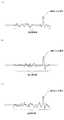
例えば、回転ミラー26の任意の角度における、ある瞬間の信号が図6(a)のように得られたとする。そして、回転ミラー26が1周して同一角度に到達したとき、再び得られた信号が図6(b)のようになった。更に、回転ミラー26が1周して同一角度に到達したとき、得られた信号が図6(c)のようになった。 For example, it is assumed that a signal at a certain moment at an arbitrary angle of the
このとき、ショットノイズは空間的に正規分布に従ってランダムに発生するのに対し、物体からの信号は常に同じ位置に存在するので、図6(a)〜図6(c)の信号を足して3で割るような処理(すなわち平均化処理)を行えば、物体からの信号だけがVthを超える信号として残る。At this time, the shot noise is randomly generated spatially according to the normal distribution, whereas the signal from the object always exists at the same position. Therefore, the signals of FIGS. 6 (a) to 6 (c) are added to 3 If the process of dividing by (that is, the averaging process) is performed, only the signal from the object remains as a signal exceedingVth.
このような平均化処理を行う場合、1回あたりの信号取得において、必ずしも物体の信号が存在する必要はない。平均化により強度が略0となったショットノイズがVthを超えることはなく、信号の誤検出のおそれがないためである。When performing such an averaging process, the signal of the object does not necessarily have to exist in each signal acquisition. This is because the shot noise whose intensity has become substantially 0 due to averagingdoes not exceed Vth, and there is no risk of erroneous signal detection.
具体的には、この平均化処理の回数をNとすると、その回数分だけ相対的にVthを引き下げる効果と同じなので、任意の同一方向への投光時に二値化回路44での二値化処理を二値化回路44からハイレベル信号が、次の(2)式で表されるM回出力されるまで行うことにより、必ず物体からの信号を検出することができる。
L=180m、fc=25MHzのとき、Vth=σsnならばM=11であったが、3回の平均化処理を実施するなら、M=2でよい、ということになる。つまり、投光1回あたりの処理回路、二値化回路44での処理時間の短縮化を図ることが可能になる。なお、Mの値を予め設定し、その設定値に対して上記(2)式を満たすようにVthを設定しても良い。L = 180m, when f c = 25MHz, but aV th =σsn If M = 11, will if performing the averaging processing of the three may be M = 2, that it. That is, it is possible to shorten the processing time in the processing circuit and the
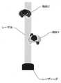
図7には、一実施形態に係る物体検出装置100が搭載された移動体としての車両1(ここでは自動車)の外観が示されている。 FIG. 7 shows the appearance of the vehicle 1 (here, the automobile) as a moving body on which the
物体検出装置100は、一例として、車両1の前方のナンバープレート近傍に取り付けられている。なお、本明細書では、XYZ3次元直交座標系において、路面に直交する方向をZ軸方向、車両1の前進方向を+X方向として説明する。 As an example, the
車両1の車内には、一例として図8に示されるように、物体検出装置100と共に監視装置110を構成する、表示装置200、主制御装置400、メモリ500、及び音声・警報発生装置600などが設けられている。監視装置110の各構成要素は、データの伝送が可能なバス700を介して電気的に接続されている。 As shown in FIG. 8 as an example, the
主制御装置400は、所定のタイミング毎に、メモリ500に格納されている物体情報などに基づいて、車両1の前方に物体があるときにその物体の移動の有無を求めるとともに、該物体が移動しているときにはその移動方向及び移動速度を含む移動情報を求める。そして、物体情報及び移動情報を表示装置200に表示する。 The
また、主制御装置400は、物体情報及び移動情報に基づいて、危険があると判断すると、音声・警報発生装置600にアラーム情報を出力する。 Further, the
音声・警報発生装置600は、一例として図9に示されるように、音声合成装置61、警報信号生成装置62及びスピーカ63などを有している。 As an example, the voice /
音声合成装置61は、複数の音声データを有しており、主制御装置400からアラーム情報を受け取ると、対応する音声データを選択し、スピーカ63に出力する。 The
警報信号生成装置62は、主制御装置400からアラーム情報を受け取ると、対応する警報信号を生成し、スピーカ63に出力する。 When the alarm
以上の説明から明らかなように、主制御装置400とメモリ500と音声・警報発生装置600とによって、本発明のセンシング装置における監視制御装置が構成されている。 As is clear from the above description, the
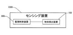
図10には、物体検出装置100を備えるセンシング装置1000が示されている。センシング装置1000は、移動体に搭載され、物体検出装置100に加えて、該物体検出装置100に電気的に接続された監視制御装置300を備えている。物体検出装置100は、車両のバンパー付近やバックミラーの近傍に取り付けられる。監視制御装置300は、物体検出装置100での検出結果に基づいて、物体の形状や大きさの推定、物体の位置情報の算出、移動情報の算出、物体の種類の認識等の処理を行って、危険の有無を判断する。そして、危険有りと判断した場合には、アラーム等の警報を発して移動体の操縦者に注意を促したり、ハンドルを切って危険を回避する指令を移動体の操舵制御部に出したり、制動をかけるための指令を移動体のECUに出す。すなわち、監視制御装置300は、物体認識部47の機能に加えて、危険有無判断機能、危険回避指令機能を有する。なお、センシング装置1000は、例えば車両のバッテリから電力の供給を受ける。 FIG. 10 shows a
なお、監視制御装置300は、物体検出装置100と一体的に設けられても良いし、物体検出装置100とは別体に設けられても良い。また、監視制御装置300は、ECUが行う制御の少なくとも一部を行っても良い。 The
ここで、物体検出装置100の製造時に、ピーク強度が閾値Vthを超えるショットノイズの出現確率(図4参照、以下では単に「出現確率」とも呼ぶ)に基づいて、二値化回路44からパルス信号(ハイレベル信号)を出力する回数(パルス数)Mを設定しても良い。具体的には、任意の同一方向(任意の同一回転角度の回転ミラー26へ入射した光の反射方向)への投光時に二値化回路44からハイレベル信号がM回出力されたときに、信号処理を終了させる。より詳細には、出現確率が例えば4/5のときには、Mを5に設定する。この場合、任意の同一方向への投光において、確率的に、出力された5個のハイレベル信号のうち1個のハイレベル信号が物体からの反射光による信号となり(図5参照)、信号処理の時間を短縮化しつつ物体からの信号を得ることができる。Here, during the manufacture of the
一般化すると、出現確率がnを自然数として(n−1)/nの場合には、ハイレベル信号がn回出力されたときに信号処理を終了させることが好ましい。出現確率が(n−1)/nでない場合には、該出現確率を最も近似する(n−1)/nに置き換えて考えても良い。
なお、信号処理の時間は多少長くなるが、出現確率がnを自然数として(n−1)/nの場合に、ハイレベル信号を出力する回数を(n+1)回以上としても良い。In generalization, when the appearance probability is (n-1) / n with n as a natural number, it is preferable to end the signal processing when the high level signal is output n times. When the appearance probability is not (n-1) / n, the appearance probability may be replaced with (n-1) / n which is the closest approximation.
Although the signal processing time is slightly longer, when the appearance probability is (n-1) / n with n as a natural number, the number of times the high level signal is output may be (n + 1) times or more.
また、物体検出装置100の製造時に、二値化回路44からハイレベル信号を出力する回数Mを設定し、その設定値に基づいて閾値Vthを設定することにより、ピーク強度が閾値Vthを超えるショットノイズの出現確率(図4参照)を設定しても良い。具体的には、Mが例えば5回に設定されているときには、出現確率が例えば4/5となるように閾値Vthを設定する。この場合、任意の投光方向において、確率的に、出力された5個のハイレベル信号のうち1個のハイレベル信号が物体からの反射光による信号となり(図5参照)、信号処理の時間を短縮化しつつ物体からの信号を得ることができる。
目標とする出現確率は、上述のように、概ね、nを自然数として(n−1)/nで表すことができる。
なお、出現確率を例えば4/5から3/5や2/5や1/5へ下げるべくVthをより高く設定しても良いが、Vthを高くするほど物体からの信号(特に弱い信号)のピークがVthを超えなくなる可能性が高まるので、Vthを高くしすぎる(出現確率を下げすぎる)のは得策ではない。Further, at the time of manufacture of the
As described above, the target appearance probability can be generally expressed by (n-1) / n with n as a natural number.
The Vth may be set higher in order to reduce the appearance probability from, for example, 4/5 to 3/5, 2/5, or 1/5,but the higher the Vth , the signal from the object (especially weak signal). ) Is more likely to not exceedVth, so it is not a good idea to make Vth too high (probability of appearance too low).
以下に、物体検出装置100が実施する測距処理1について、図11のフローチャートを参照して説明する。 The
最初のステップS1では、投光処理を行う。具体的には、測定制御部46がLD駆動信号を生成し、有効走査領域における任意の投光方向(走査位置)へ投光を行う。 In the first step S1, the light projection process is performed. Specifically, the
次のステップS2では、受光処理を行う。具体的には、光検出器43が、任意の投光方向への投光時に受光した光を光電変換、電流電圧変換、さらには必要に応じて信号増幅、低周波カットし、得られた電圧信号を二値化回路44へ出力する。 In the next step S2, the light receiving process is performed. Specifically, the
次のステップS3では、二値化処理を行う。具体的には、二値化回路44が、入力された各電圧信号を二値化し、ハイレベル信号を時間計測部45へ出力する。より詳細には、時間計測部45が、二値化回路44から時間計測部45へのハイレベル信号の出力回数(カウント数)が上記(1)式のMになったときに処理回路60−1又は処理回路60−2、及び二値化回路44での信号処理を終了させ、所定時間経過後に次の投光方向への投光に備えてカウント数を0に初期化する。 In the next step S3, the binarization process is performed. Specifically, the
次のステップS4では、信号抽出処理を行う。具体的には、時間計測部45が、入力されたM個のハイレベル信号のパルス幅をLD駆動信号(パルス幅が受光信号と略同一)のパルス幅と比較し、LD駆動信号のパルス幅にパルス幅が最も近似するハイレベル信号を物体からの信号として抽出する。 In the next step S4, signal extraction processing is performed. Specifically, the
次のステップS5では、時間計測処理を行う。具体的には、時間計測部45が、入力されたハイレベル信号に基づいて光検出器43での受光タイミングを算出し、該受光タイミングとLDの発光タイミングとの時間差を測定制御部46へ出力する。 In the next step S5, the time measurement process is performed. Specifically, the
次のステップS6では、距離算出処理を行う。具体的には、測定制御部46が、入力された時間差から、物体までの距離を算出し、その距離データを物体認識部47へ出力する。 In the next step S6, the distance calculation process is performed. Specifically, the
次のステップS7では、測定制御部46が測定を終了するか否かを判断する。具体的には、車両1の電気系統がOFFになったときにここでの判断を肯定してフローを終了させ、それ以外のときはここでの判断を否定してステップS1へ戻り、測定を継続する。なお、ステップS1〜ステップS7の1ループで有効走査領域が1回走査されるものとする。 In the next step S7, the
なお、図11のフローチャートにおいて、走査位置間で(投光方向間で)複数のステップを一部並行して行っても良い。 In the flowchart of FIG. 11, a plurality of steps may be partially performed in parallel between the scanning positions (between the projection directions).
以下に、物体検出装置100が実施する測距処理2について、図12のフローチャートを参照して説明する。図13(A)及び図13(B)には、それぞれ測距処理2に用いられる光検出器43−1を含む検出系の構成例、光検出器43−2を含む検出系の構成例が示されている。図13では、図3と同じ構成については、同じ符号を付している。ここでは、図13に示されるように、処理回路60−1又は処理回路60−2と、二値化回路44との間に平均化回路51が接続されている。また、制御部49は、平均化回路51の制御を行う。 The distance measuring process 2 performed by the
最初のステップS11では、投光処理を行う。具体的には、測定制御部46がLD駆動信号を生成し、有効走査領域における任意の投光方向(走査位置)へ投光を行う。 In the first step S11, the light projection process is performed. Specifically, the
次のステップS12では、受光処理を行う。具体的には、光検出器43が、任意の投光方向への投光時に受光した光を光電変換、電流電圧変換、さらには必要に応じて信号増幅、低周波カットし、電圧信号を得る。 In the next step S12, the light receiving process is performed. Specifically, the
次のステップS13では、信号蓄積処理を行う。具体的には、平均化回路51が、入力された電圧信号を有効走査領域の走査位置毎(投光方向毎)に蓄積する。 In the next step S13, the signal storage process is performed. Specifically, the averaging
次のステップS14では、信号蓄積回数がN(>1)よりも少ないか否かを判断する。具体的には、制御部49が、蓄積された走査位置毎の電圧信号の数がNよりも少ないか否かを判断する。ここでの判断が肯定されるとステップS11に戻り、否定されるとステップS15へ進む。ステップS15へ進む際、制御部49が、平均化回路51へN個の電圧信号を平均化する指示を与える。なお、ステップS11〜ステップS14の1ループで有効走査領域が1回走査されるものとする。 In the next step S14, it is determined whether or not the number of signal accumulations is less than N (> 1). Specifically, the
ステップS15では、平均化処理を行う。具体的には、平均化回路51が、制御部49からの指示により、入力された走査位置毎のN個の電圧信号を平均化し、平均化された電圧信号を二値化回路44へ出力する。 In step S15, the averaging process is performed. Specifically, the averaging
次のステップS16では、二値化処理を行う。具体的には、二値化回路44が、制御部49からの指示により、入力された各電圧信号を二値化し、ハイレベル信号を時間計測部45へ出力する。より詳細には、制御部49が、二値化回路44から時間計測部45へのハイレベル信号の出力回数(カウント数)が上記(2)式のMになったときに処理回路及び二値化回路44での信号処理を終了させ、所定時間経過後に次の投光方向への投光に備えてカウント数を0に初期化する。 In the next step S16, the binarization process is performed. Specifically, the
次のステップS17では、信号抽出処理を行う。具体的には、時間計測部45が、入力されたM個のハイレベル信号のパルス幅をLD駆動信号(パルス幅が受光信号と略同一)のパルス幅と比較し、LD駆動信号パルス幅が最も近似するハイレベル信号を物体からの信号として抽出する。 In the next step S17, the signal extraction process is performed. Specifically, the
次のステップS18では、時間計測処理を行う。具体的には、時間計測部45が、入力されたハイレベル信号に基づいて光検出器43での受光タイミングを求め、該受光タイミングとLDの発光タイミングとの時間差を測定制御部46へ出力する。 In the next step S18, the time measurement process is performed. Specifically, the
次のステップS19では、距離算出処理を行う。具体的には、測定制御部46が、入力された時間差から、物体までの距離を算出し、その距離データを物体認識部47へ出力する。 In the next step S19, the distance calculation process is performed. Specifically, the
次のステップS20では、測定制御部46が測定を終了するか否かを判断する。具体的には、車両1の電気系統がOFFになったときにここでの判断を肯定してフローを終了させ、それ以外のときはここでの判断を否定してステップS11へ戻り、測定を継続する。 In the next step S20, the
なお、図14のフローチャートにおいて、走査位置間で(投光方向間で)複数のステップを一部並行して行っても良い。 In the flowchart of FIG. 14, a plurality of steps may be partially performed in parallel between the scanning positions (between the projection directions).
以上説明した本実施形態の物体検出装置100は、第1の観点からすると、光源(例えばLD)からの光を投光し物体で反射された光を受光素子(例えばPD)で受光することで物体検出を行う物体検出装置であって、受光素子からの信号を閾値Vthで二値化する二値化回路44を備え、二値化回路44で二値化された信号のうちハイレベル信号がM回出力されるまで、同一方向について物体検出動作を行い、Mの値は、受光素子におけるピーク強度が閾値Vthを超えるショットノイズの出現確率に基づいて設定されていることを特徴とする物体検出装置である。
なお、「受光素子におけるピーク強度が閾値Vthを超えるショットノイズの出現確率」は、ショットノイズの強度分布(図4参照)と閾値Vthにより決まるため、「当該出現確率に基づいてMの値が設定されている」ことは、「閾値Vth及びショットノイズの強度分布に基づいてMの値が設定されている」ことと同義である。From the first viewpoint, the
Since the "probability of appearance of shot noise whose peak intensity exceeds the threshold value Vth in the light receiving element" is determined by the intensity distribution of shot noise (see FIG. 4) and the threshold valueVth , "the value of M based on the occurrence probability". Is set, which is synonymous with "the value of M is set based on thethreshold Vth and the intensity distribution of shot noise."
また、本実施形態の物体検出装置100は、第2の観点からすると、光源(例えばLD)からの光を投光し物体で反射された光を受光素子(例えばPD)で受光することで物体検出を行う物体検出装置であって、受光素子からの信号を閾値Vthで二値化する二値化回路44を備え、二値化回路44で二値化された信号のうちハイレベル信号がM回出力されるまで、同一方向について物体検出動作を行い、Mの値に基づいて、閾値Vthが設定されていることを特徴とする物体検出装置である。Further, from the second viewpoint, the
本実施形態の物体検出装置100によれば、ピーク強度が閾値Vthを超えるショットノイズの出現確率によらず、物体からの信号を検出(二値化)できる。この結果、誤検出を抑制することができる。なお、本実施形態の物体検出装置100では、複数の投光方向へ投光する構成を採用しているが、単一の投光方向へ投光する構成を採用しても良い。According to the
また、Mは、ショットノイズの個数よりも多いことが好ましい。この場合、物体からの信号を確実に検出(二値化)できる。 Further, M is preferably larger than the number of shot noises. In this case, the signal from the object can be reliably detected (binarized).
また、Mは、ショットノイズの個数よりも1つだけ多いことが好ましい。この場合、信号処理の回数を極力低減しつつ(処理速度を極力高速化しつつ)、物体からの信号を確実に検出(二値化)できる。 Further, it is preferable that M is one more than the number of shot noises. In this case, the signal from the object can be reliably detected (binarized) while reducing the number of times of signal processing as much as possible (while increasing the processing speed as much as possible).
また、物体検出装置100が検出可能な物体までの最大距離をL、物体で反射された光による信号のパルス幅をωobj、ショットノイズの標準偏差をσsn、光速をc、標準正規累積分布関数をF(Vth、0、σsn)としたとき、M≧F(−Vth、0、σsn)×(2L/c)×(1/ωobj)+1を満足することが好ましい。この場合、物体からの信号を確実に検出できる。Further, the maximum distance to the object that can be detected by the
また、同一方向へN回投光したときに入力される、複数の信号をそれぞれが含むN個の信号群を平均化するための平均化回路51を含んでいても良い。
この場合、物体検出装置100が検出可能な物体までの最大距離をL、物体で反射された光による信号のパルス幅をωobj、ショットノイズの標準偏差をσsn、光速をc、標準正規累積分布関数をF(Vth、0、σsn)としたとき、M≧F(−Vth/N、0、σsn)×(2L/c)×(1/ωobj)+1を満足することが好ましい。この結果、物体からの信号を確実に検出できる。Further, an averaging
In this case, the maximum distance to the object that can be detected by the
また、M個のハイレベル信号のパルス幅に基づいて、M個のハイレベル信号から、物体で反射された光によるハイレベル信号を抽出することが好ましい。 Further, it is preferable to extract the high level signal due to the light reflected by the object from the M high level signals based on the pulse width of the M high level signals.
また、物体で反射された光による二値化信号に基づいて受光素子での受光タイミングを算出し、投光時における光源の発光タイミング及び受光タイミングに基づいて、物体までの距離を算出することが好ましい。 In addition, the light receiving timing at the light receiving element can be calculated based on the binarized signal due to the light reflected by the object, and the distance to the object can be calculated based on the light emitting timing and the light receiving timing of the light source at the time of projection. preferable.
また、光源からの光を投光する方向は、複数の方向であり、該複数の方向における物体までの距離に基づいて、該物体の形状を推定しても良い。 Further, the directions in which the light from the light source is projected are a plurality of directions, and the shape of the object may be estimated based on the distances to the objects in the plurality of directions.
また、本実施形態の物体検出装置100と、該物体検出装置100の出力に基づいて、物体の移動の有無、移動方向及び移動速度の少なくともいずれかを含む移動情報を求める監視制御装置300と、を備えるセンシング装置1000によれば、物体に関する情報を精度良く取得できる。 Further, the
また、本実施形態の物体検出装置100は、物体の位置情報及び移動情報の少なくとも一方を表示する表示装置200を更に備えていても良い。この場合、物体の位置情報及び移動情報の少なくとも一方を精度良く表示できる。 Further, the
また、センシング装置1000は移動体に搭載され、監視制御装置300は物体の位置情報及び移動情報の少なくとも一方に基づいて危険の有無を判断するため、例えば移動体の操縦処理系、速度処理系等に危険回避のための有効な情報を提供することができる。 Further, the
また、移動体(例えば車両1)と、該移動体に搭載されるセンシング装置1000と、を備える移動体装置(例えば車両装置)によれば、衝突安全性に優れる。 Further, according to the mobile device (for example, the vehicle device) including the moving body (for example, the vehicle 1) and the
また、本実施形態の物体検出方法は、第1の観点からすると、複数の投光方向へ投光し物体で反射された光を受光素子(例えばPD)で受光して、物体に関する情報を検出する物体検出方法であって、各投光方向へ投光する工程と、該投光時に受光素子からの信号に対して閾値Vthで二値化する二値化処理を含む処理を行う工程と、を含み、二値化処理で二値化された信号のうちハイレベル信号をM回出力するまで、同一方向について物体に関する情報を検出する動作を行い、Mの値は、受光素子におけるピーク強度が閾値Vthを超えるショットノイズの出現確率に基づいて設定されていることを特徴とする物体検出方法である。Further, from the first viewpoint, the object detection method of the present embodiment detects information about an object by projecting light in a plurality of light projection directions and receiving the light reflected by the object with a light receiving element (for example, PD). A method of detecting an object to be performed, which includes a step of projecting light in each light projecting direction and a step of performing a binarization process of binarizing a signal from a light receiving element at a threshold value Vth at the time of projecting. , And the operation to detect information about the object in the same direction until the high level signal is output M times among the signals binarized by the binarization process, and the value of M is the peak intensity in the light receiving element. Is an object detection method characterized in that is set based on the appearance probability of shot noise exceeding the threshold value Vth.
また、本実施形態の物体検出方法は、第2の観点からすると、複数の投光方向へ投光し物体で反射された光を受光素子(例えばPD)で受光して、物体に関する情報を検出する物体検出方法であって、各投光方向へ投光する工程と、該投光時に受光素子からの信号に対して、閾値Vthで二値化する二値化処理を含む処理を行う工程と、を含み、二値化処理で二値化された信号のうちハイレベル信号をM回出力するまで、同一方向について物体に関する情報を検出する動作を行い、Mの値に基づいて、閾値Vthが設定されていることを特徴とする物体検出方法である。Further, from the second viewpoint, the object detection method of the present embodiment detects information about the object by projecting light in a plurality of light projection directions and receiving the light reflected by the object with a light receiving element (for example, PD). This is an object detection method that includes a step of projecting light in each light projecting direction and a binarization process of binarizing a signal from a light receiving element at the time of projecting light with a threshold valueVth. And, and, among the signals binarized by the binarization process, the operation of detecting the information about the object in the same direction is performed until the high level signal is output M times, and the threshold value V is performed based on the value of M.This is an object detection method characterized in that th is set.
本実施形態の物体検出方法によれば、ピーク強度が閾値Vthを超えるショットノイズの出現確率によらず、物体からの信号を検出(二値化)できる。この結果、誤検出を抑制することができる。According to the object detection method of the present embodiment, the signal from the object can be detected (binarized) regardless of the appearance probability of shot noise whosepeak intensity exceeds the threshold value Vth. As a result, erroneous detection can be suppressed.
また、当該物体検出方法における検出可能な物体までの最大距離をL、前記物体で反射された光による信号のパルス幅をωobj、前記ショットノイズの標準偏差をσsn、光速をc、標準正規累積分布関数をF(Vth、0、σsn)としたとき、M≧F(−Vth、0、σsn)×(2L/c)×(1/ωobj)+1を満足することが好ましい。Further, the maximum distance to a detectable object in the object detection method is L, the pulse width of the signal due to the light reflected by the object is ωobj , the standard deviation of the shot noise is σsn , the light speed is c, and the standard normal. When the cumulative distribution function is F (Vth , 0, σsn ), it is possible to satisfy M ≧ F (−Vth , 0, σsn ) × (2 L / c) × (1 / ωobj) +1. preferable.
また、投光する工程がN回行われ、各回の投光時に受光素子から出力された電流に基づく複数の信号を含む信号群を蓄積する工程と、蓄積されたN個の信号群を平均化する工程と、を更に含むことが好ましい。 In addition, the step of projecting light is performed N times, and the process of accumulating a signal group including a plurality of signals based on the current output from the light receiving element at each time of projecting and the step of accumulating the accumulated N signal groups are averaged. It is preferable to further include the step of performing.
また、当該物体検出方法における検出可能な物体までの最大距離をL、前記物体で反射された光による信号のパルス幅をωobj、前記ショットノイズの標準偏差をσsn、光速をc、標準正規累積分布関数をF(Vth、0、σsn)としたとき、M≧F(−Vth/N、0、σsn)×(2L/c)×(1/ωobj)+1を満足することが好ましい。Further, the maximum distance to a detectable object in the object detection method is L, the pulse width of the signal due to the light reflected by the object is ωobj , the standard deviation of the shot noise is σsn , the speed of light is c, and the standard normal. When the cumulative distribution function is F (Vth , 0, σsn ), M ≧ F (−Vth / N, 0, σsn ) × (2L / c) × (1 / ωobj ) +1 is satisfied. Is preferable.
また、処理を行う工程で得られたM個のハイレベル信号のパルス幅に基づいて、M個のハイレベル信号から、物体で反射された光によるハイレベル信号を抽出する工程を更に含むことが好ましい。 Further, a step of extracting a high-level signal due to light reflected by an object from the M high-level signals based on the pulse width of the M high-level signals obtained in the process of processing may be further included. preferable.
なお、上記実施形態では、回転ミラー26が2つの鏡面を有する場合について説明したが、これに限定されるものではない。 In the above embodiment, the case where the
また、上記実施形態において、物体検出装置100をZ軸まわりに回動させる回動機構を有していても良い。 Further, in the above embodiment, a rotation mechanism for rotating the
また、上記実施形態において、カップリングレンズ22の焦点距離f1と、結像光学系の焦点距離f2とは、等しくても良い。この場合は、カップリングレンズ22と結像光学系とを共通化することができ、コスト低減を図ることができる。In the above embodiment, the focal length f1 of the
また、上記実施形態において、測定制御部46での処理の一部を主制御装置400が行っても良いし、主制御装置400での処理の一部を測定制御部46が行っても良い。 Further, in the above embodiment, the
また、上記実施形態では、監視装置が1つの物体検出装置100を備える場合について説明したが、これに限定されるものではない。車両の大きさ、監視領域などに応じて、複数の物体検出装置100を備えても良い。 Further, in the above embodiment, the case where the monitoring device includes one
また、上記実施形態では、物体検出装置100が車両の進行方向を監視する監視装置に用いられる場合について説明したが、これに限定されるものではない。例えば、車両の後方や側面を監視する装置に用いられても良い。 Further, in the above embodiment, the case where the
さらに、上記実施形態の物体検出装置100は、車載用以外のセンシング装置にも用いることができる。この場合には、主制御装置400は、センシングの目的に応じたアラーム情報を出力する。 Further, the
また、上記実施形態の物体検出装置100は、物体の有無のみを検出する用途にも用いることができる。この場合には、時間計測部45や物体認識部47が不要であり、測定制御部46で物体までの距離を算出する必要もない。 In addition, the
また、上記実施形態の物体検出装置100は、物体までの距離のみを検出する用途にも用いることができる。この場合には、物体認識部47が不要である。 Further, the
また、上記実施形態の物体検出装置100は、監視装置やセンシング装置以外の用途(例えば、距離計測装置や形状測定装置)にも用いることができる。 Further, the
また、上記実施形態の物体検出装置100において、光検出器43の処理回路の構成部品間にスイッチを設けて信号の流れを遮断可能としても良い。 Further, in the
また、上記実施形態では、発光素子として、単一のLDを用いているが、これに限られない。例えば、複数のLDが1次元又は2次元に配列されたLDアレイ、VCSEL(面発光レーザ)、VCSELが1次元又は2次元に配列されたVCSELアレイ、他のレーザ、LED(発光ダイオード)、複数のLEDが1次元又は2次元に配列されたLEDアレイ、有機EL素子、複数の有機EL素子が1次元又は2次元に配列された有機ELアレイなどを用いても良い。複数のLDが1次元配列されたLDアレイとしては、複数のLDが積層されたスタック型のLDアレイや複数のLDが横に並べられたLDアレイが挙げられる。例えば、半導体レーザとして、LDをVCSELに代えれば、アレイ内の発光点の数をより多く設定することができる。 Further, in the above embodiment, a single LD is used as the light emitting element, but the present invention is not limited to this. For example, an LD array in which a plurality of LDs are arranged one-dimensionally or two-dimensionally, a VCSEL (plane emitting laser), a VCSEL array in which VCSELs are arranged one-dimensionally or two-dimensionally, another laser, an LED (light emitting diode), a plurality of An LED array in which the LEDs are arranged one-dimensionally or two-dimensionally, an organic EL element, an organic EL array in which a plurality of organic EL elements are arranged one-dimensionally or two-dimensionally, or the like may be used. Examples of the LD array in which a plurality of LDs are arranged one-dimensionally include a stack type LD array in which a plurality of LDs are stacked and an LD array in which a plurality of LDs are arranged side by side. For example, as a semiconductor laser, if the LD is replaced with a VCSEL, the number of light emitting points in the array can be set to be larger.
また、処理回路は、信号増幅器及びハイパスフィルタ(HPF)の少なくとも一方を有していなくても良い。すなわち、処理回路は、電流電圧変換器で構成されても良いし、電流電圧変換器と信号増幅器とで構成されても良いし、電流電圧変換器とハイパスフィルタとで構成されても良い。 Further, the processing circuit may not have at least one of a signal amplifier and a high-pass filter (HPF). That is, the processing circuit may be composed of a current-voltage converter, a current-voltage converter and a signal amplifier, or a current-voltage converter and a high-pass filter.
また、投光光学系は、カップリングレンズを有していなくても良いし、他のレンズを有していても良い。 Further, the projectile optical system may not have a coupling lens or may have another lens.
また、投光光学系、受光光学系は、反射ミラーを有していなくても良い。すなわち、LDからの光を、光路を折り返さずに回転ミラーに入射させ、物体で反射され回転ミラーに入射した光を、光路を折り返さずにPDへ入射させても良い。 Further, the light projecting optical system and the light receiving optical system do not have to have a reflection mirror. That is, the light from the LD may be incident on the rotating mirror without folding back the optical path, and the light reflected by the object and incident on the rotating mirror may be incident on the PD without folding back the optical path.
また、受光光学系の結像光学系は、レンズに代えて又は加えて、他の光学素子(例えば集光ミラー)を有していても良い。 Further, the imaging optical system of the light receiving optical system may have another optical element (for example, a condensing mirror) in place of or in addition to the lens.
また、偏向器として、回転ミラーに代えて、例えば、ポリゴンミラー(回転多面鏡)、ガルバノミラー、MEMSミラー等の他のミラーを用いても良い。 Further, as the deflector, for example, another mirror such as a polygon mirror (rotating polymorphic mirror), a galvano mirror, or a MEMS mirror may be used instead of the rotating mirror.
また、同期系は、結像レンズに代えて、他の光学素子(例えば集光ミラー)を有していても良い。 Further, the synchronous system may have another optical element (for example, a condensing mirror) instead of the imaging lens.
また、上記実施形態では、物体検出装置100として、走査型レーザレーダが用いられているが、非走査型のレーザレーダを用いても良い。また、レーザレーダに代えて、電波を使用するミリ波レーダを用いても良い。ミリ波レーダは、分解能がレーザレーダよりも劣るものの、天候に関わらず検知可能であり、測定可能な距離範囲も広い。 Further, in the above embodiment, the scanning laser radar is used as the
また、上記実施形態では、物体検出装置が搭載される移動体として自動車を例にとって説明したが、該移動体は、自動車以外の車両、航空機、船舶等であっても良い。 Further, in the above embodiment, an automobile is described as an example of a moving body on which the object detection device is mounted, but the moving body may be a vehicle, an aircraft, a ship, or the like other than the automobile.
また、以上の説明で用いた具体的な数値、形状などは、一例であって、本発明の趣旨を逸脱しない範囲で適宜変更可能なことは言うまでもない。 Further, it goes without saying that the specific numerical values and shapes used in the above description are examples and can be appropriately changed without departing from the spirit of the present invention.
以上の説明から明らかなように、上記実施形態の物体検出装置100、監視装置110、センシング装置1000、移動体装置、物体検出方法は、物体に関する情報を検出する所謂Time of Flight(TOF)法を用いる技術又はTOF法に用いられる技術であり、移動体におけるセンシングの他、モーションキャプチャ技術、測距計、3次元形状計測技術などの産業分野などで幅広く用いることができる。すなわち、本発明の物体検出装置、センシング装置は、必ずしも移動体に搭載されなくても良い。 As is clear from the above description, the
以下に、発明者らが上記実施形態を発案するに至った思考プロセスについて説明する。 The thinking process that led to the invention of the above embodiment by the inventors will be described below.
近年、物体の有無や、その物体までの距離を検出するための物体検出装置の開発が盛んに行われている。その一例として航空機や鉄道、車載など広く使用されているレーザレーダがある。レーザレーダとしては様々なものが知られているが、例えば特許文献1〜4に開示されているように、投光部から射出された光を回転ミラーで走査し、物体で反射もしくは散乱された光を、再度回転ミラーを介して受光部で受光することで、所望の範囲の物体の有無やその物体までの距離を検出できる走査型レーザレーダがある。 In recent years, an object detection device for detecting the presence or absence of an object and the distance to the object has been actively developed. One example is laser radar, which is widely used in aircraft, railways, and vehicles. Various laser radars are known. For example, as disclosed in
このようなレーザレーダでの測距において重要になるのが、ノイズと、物体からの信号との分離である。ノイズの中でもショットノイズは光量計測に伴う白色雑音であり、ショットノイズの大きさは、受光部の感度が高い、もしくは外乱光が強い場合には、物体からの信号と区別が難しくなるため、回路ノイズよりも問題になりやすい。 What is important in distance measurement with such a laser radar is the separation of noise and a signal from an object. Among the noise, shot noise is white noise that accompanies the measurement of the amount of light, and the magnitude of shot noise is difficult to distinguish from the signal from an object when the sensitivity of the light receiving part is high or the ambient light is strong. More problematic than noise.
図14に、任意の画角(投光方向)におけるショットノイズと、物体からの信号とが混在している状況が示されている。
これらの信号(ショットノイズを含む)のうち、閾値Vthを超えた信号が、演算部で処理される信号(距離演算に用いられる信号)の候補となる。図14では、M=8個の信号が演算部で処理される信号の候補となり、物体からの信号は5番目と8番目となっている。FIG. 14 shows a situation in which shot noise at an arbitrary angle of view (projection direction) and a signal from an object are mixed.
Among these signals (including shot noise),the signal exceeding the threshold value Vth is a candidate for the signal processed by the calculation unit (the signal used for the distance calculation). In FIG. 14, M = 8 signals are candidates for signals processed by the calculation unit, and the signals from the object are the 5th and 8th signals.
このような状況は、例えば図15に示されるように、レーザレーダの任意の画角の前後(異なる距離)に2つの物体が存在し、投光されたレーザ光の一部が前方(近距離側)の物体1に照射され、残部が後方(遠距離側)の物体2に照射されるときに起こる。 In such a situation, for example, as shown in FIG. 15, two objects exist before and after (different distances) at an arbitrary angle of view of the laser radar, and a part of the projected laser light is forward (short distance). It occurs when the
距離演算に用いられる情報は、信号がVthを切る立ち上がり時刻trと立下り時刻tfの組み合わせでしかない。この組み合わせから、物体からの信号とショットノイズとを分離するのは容易でない。Information used for distance calculation, the signal is only a combination of the rise time tr and fall time tf to cut Vth. From this combination, it is not easy to separate the signal from the object and the shot noise.
そこで、Vthを高く設定し、できるだけショットノイズが演算部で処理される状況を低減する方法が考えられる。しかし、この方法は次のような2つの問題点を惹起する。
一つ目の問題は、測距可能な最大距離が低減することである。一般に、レーザレーダから物体までの距離が長くなれば、反射もしくは散乱された光のピーク強度は低下し、Vthを超えなくなってくる。
二つ目の問題は、そもそもショットノイズの物理的な性質から、Vthをどれだけ高く設定しても、確率論的にVthを超えるショットノイズは存在することである。
このことから、Vthを徒に高く設定することは好ましくなく、適切な高さに設定し、ピーク強度がVthを超える信号すべてを演算部で処理される信号の候補とし、その候補を物体からの信号とショットノイズとに分離することが望ましい。Therefore,it is conceivable to set Vth high to reduce the situation where shot noise is processed by the calculation unit as much as possible. However, this method raises the following two problems.
The first problem is that the maximum distance that can be measured is reduced. Generally, as the distance from the laser radar to the object increases, the peak intensity of the reflected or scattered light decreases and does not exceedVth.
The second problem is that, due to the physical nature of shot noise, shot noise that stochasticallyexceeds V th exists no matterhow high V th is set.
For this reason, itis not preferable to set Vth unnecessarily high, set it to an appropriate height, and setall signals whose peak intensities exceed Vth as signal candidates to be processed by the arithmetic unit, and set the candidates as object candidates. It is desirable to separate the signal from and the shot noise.
ところで、ピーク強度がVthを超える信号が全部でM個ある場合、その処理時間は、1つの信号を処理する時間τのM倍になる。
Mを多くすれば、物体からの信号を確実にキャッチできるが、処理部における処理時間が増え、フレームレートが遅くなる。一方で、Mを少なくする場合には、ショットノイズの数をMよりも充分に少なくする必要がある。このことは、測距可能な最大距離を低減することに他ならない。By the way,when there are M signals having a peak intensity exceeding Vth in total, the processing time is M times the time τ for processing one signal.
If M is increased, the signal from the object can be reliably caught, but the processing time in the processing unit increases and the frame rate becomes slow. On the other hand, when reducing M, it is necessary to make the number of shot noises sufficiently smaller than M. This is nothing but reducing the maximum distance that can be measured.
よって、測距可能な最大距離とVthの設定値から、Mの数を適切に設定する必要があることが明らかになってきた。もしくは、測距可能な最大距離とMの設定値から、Vthの値を適切に設定する必要があることが明らかになってきた。Therefore, it has become clear that it is necessary to appropriately set the number of M from the maximum distance that can be measured andthe set value of Vth. Alternatively, it has become clear that it is necessary to appropriately set theVth value from the maximum distance that can be measured and the set value of M.
そこで、発明者らは、このような知見に基づき、上記実施形態を発案するに至った。 Therefore, the inventors have come up with the above-mentioned embodiment based on such findings.
1…車両(移動体)、42…時間計測用PD(受光素子)、44…二値化回路、51…平均化回路、100…物体検出装置、300…監視制御装置、1000…センシング装置。 1 ... Vehicle (moving body), 42 ... PD (light receiving element) for time measurement, 44 ... Binarization circuit, 51 ... Average circuit, 100 ... Object detection device, 300 ... Monitoring control device, 1000 ... Sensing device.
Claims (16)
Translated fromJapanese前記受光素子からの信号を閾値Vthで二値化する二値化回路を備え、
前記二値化回路で二値化された信号のうちハイレベル信号がM回出力されるまで、同一方向について物体検出動作を行い、
Mの値は、前記受光素子におけるピーク強度が閾値Vthを超えるショットノイズの出現確率に基づいて設定されていることを特徴とする物体検出装置。It is an object detection device that detects an object by projecting light from a light source and receiving the light reflected by the object with a light receiving element.
A binarizing circuit that binarizes the signal from the light receiving element at the threshold value Vth is provided.
The object detection operation is performed in the same direction until the high level signal of the binarized signals in the binarization circuit is output M times.
An object detection device characterized in that the value of M is set based on the appearance probability of shot noise whose peak intensity in the light receiving element exceeds the threshold value Vth.
M≧F(−Vth、0、σsn)×(2L/c)×(1/ωobj)+1
を満足することを特徴とする請求項1に記載の物体検出装置。The maximum distance to an object that can be detected by the object detection device is L, the pulse width of the signal due to the light reflected by the object is ωobj, the standard deviation of the shot noise is σsn, the speed of light is c, and the standard normal cumulative distribution function is set. When F (Vth, 0, σsn)
M ≧ F (−Vth, 0, σsn) × (2L / c) × (1 / ωobj) +1
The object detection device accordingto claim 1, wherein the object detection device is characterized in that.
M≧F(−Vth/N、0、σsn)×(2L/c)×(1/ωobj)+1
を満足することを特徴とする請求項3に記載の物体検出装置。The maximum distance to an object that can be detected by the object detection device is L, the pulse width of the signal due to the light reflected by the object is ωobj, the standard deviation of the shot noise is σsn, the speed of light is c, and the standard normal cumulative distribution function is set. When F (Vth, 0, σsn)
M ≧ F (−Vth / N, 0, σsn) × (2L / c) × (1 / ωobj) +1
The object detection device according to claim 3 , wherein the object detection device is characterized in that.
投光時における前記光源の発光タイミング及び前記受光タイミングに基づいて、前記物体までの距離を算出することを特徴とする請求項1〜5のいずれか一項に記載の物体検出装置。The light receiving timing at the light receiving element is calculated based on the high level signal due to the light reflected by the object.
The object detection device according to any one ofclaims 1 to 5 , wherein the distance to the object is calculated based on the light emission timing of the light source and the light reception timing at the time of light projection.
前記複数の方向における前記物体までの距離に基づいて、該物体の形状を推定することを特徴とする請求項1〜6のいずれか一項に記載の物体検出装置。The directions in which the light from the light source is projected are a plurality of directions.
The object detection device according to any one ofclaims 1 to 6 , wherein the shape of the object is estimated based on the distances to the object in the plurality of directions.
前記物体検出装置の出力に基づいて、物体の移動の有無、移動方向及び移動速度の少なくとも1つを含む移動情報を求める監視制御装置と、を備えるセンシング装置。The object detection device according to any one of claims 1 to7.
A sensing device including a monitoring control device that obtains movement information including at least one of the presence / absence of movement, a movement direction, and a movement speed of an object based on the output of the object detection device.
前記監視制御装置は、前記物体の位置情報及び移動情報の少なくとも一方に基づいて危険の有無を判断することを特徴とする請求項8又は9に記載のセンシング装置。Mounted on a mobile body,
The sensing device accordingto claim 8 or 9 , wherein the monitoring control device determines the presence or absence of danger based on at least one of the position information and the movement information of the object.
前記センシング装置が搭載される移動体と、を備える移動体装置。The sensing device according to any one of claims8 to 10.
A mobile device including a mobile body on which the sensing device is mounted.
前記投光方向へ投光する工程と、
前記投光時に前記受光素子からの信号に対して閾値Vthで二値化する二値化処理を含む処理を行う工程と、を含み、
前記二値化処理で二値化された信号のうちハイレベル信号をM回出力するまで、同一方向について前記物体に関する情報を検出する動作を行い、
Mの値は、前記受光素子におけるピーク強度が閾値Vthを超えるショットノイズの出現確率に基づいて設定されていることを特徴とする物体検出方法。An object detection method for detecting information about an object by projecting light in at least one projection direction and receiving the light reflected by the object with a light receiving element.
The process of projecting light in the light projecting direction and
A step of performing a process including a binarization process of binarizing a signal from the light receiving element at a threshold value Vth at the time of light projection is included.
The operation of detecting the information about the object in the same direction is performed until the high level signal of the binarized signals in the binarization process is output M times.
A method for detecting an object, wherein the value of M is set based on the appearance probability of shot noise whose peak intensity in the light receiving element exceeds the threshold value Vth.
M≧F(−Vth、0、σsn)×(2L/c)×(1/ωobj)+1
を満足することを特徴とする請求項12に記載の物体検出方法。The maximum distance to a detectable object in the object detection method is L, the pulse width of the signal due to the light reflected by the object is ωobj, the standard deviation of the shot noise is σsn, the speed of light is c, and the standard normal cumulative distribution function is set. When F (Vth, 0, σsn)
M ≧ F (−Vth, 0, σsn) × (2L / c) × (1 / ωobj) +1
The object detection method according to claim12, wherein the object is satisfied.
各回の投光時に前記受光素子から出力された電流に基づく複数の信号を含む信号群を蓄積する工程と、
蓄積されたN個の信号群を平均化する工程と、を更に含むことを特徴とする請求項12に記載の物体検出方法。The step of projecting light is performed N times,
A step of accumulating a signal group including a plurality of signals based on the current output from the light receiving element at each time of light projection, and a step of accumulating a signal group.
The object detection method accordingto claim 12 , further comprising a step of averaging the accumulated N signal groups.
M≧F(−Vth/N、0、σsn)×(2L/c)×(1/ωobj)+1
を満足することを特徴とする請求項14に記載の物体検出方法。The maximum distance to a detectable object in the object detection method is L, the pulse width of the signal due to the light reflected by the object is ωobj, the standard deviation of the shot noise is σsn, the speed of light is c, and the standard normal cumulative distribution function is set. When F (Vth, 0, σsn)
M ≧ F (−Vth / N, 0, σsn) × (2L / c) × (1 / ωobj) +1
The object detection method according to claim14, wherein the object is satisfied.
Priority Applications (2)
| Application Number | Priority Date | Filing Date | Title |
|---|---|---|---|
| JP2017157859AJP6933045B2 (en) | 2017-08-18 | 2017-08-18 | Object detection device, sensing device, mobile device and object detection method |
| US16/053,004US11150345B2 (en) | 2017-08-18 | 2018-08-02 | Object detector, sensing device, and mobile object apparatus |
Applications Claiming Priority (1)
| Application Number | Priority Date | Filing Date | Title |
|---|---|---|---|
| JP2017157859AJP6933045B2 (en) | 2017-08-18 | 2017-08-18 | Object detection device, sensing device, mobile device and object detection method |
Publications (2)
| Publication Number | Publication Date |
|---|---|
| JP2019035690A JP2019035690A (en) | 2019-03-07 |
| JP6933045B2true JP6933045B2 (en) | 2021-09-08 |
Family
ID=65361185
Family Applications (1)
| Application Number | Title | Priority Date | Filing Date |
|---|---|---|---|
| JP2017157859AActiveJP6933045B2 (en) | 2017-08-18 | 2017-08-18 | Object detection device, sensing device, mobile device and object detection method |
Country Status (2)
| Country | Link |
|---|---|
| US (1) | US11150345B2 (en) |
| JP (1) | JP6933045B2 (en) |
Families Citing this family (12)
| Publication number | Priority date | Publication date | Assignee | Title |
|---|---|---|---|---|
| US11011257B2 (en) | 2018-11-21 | 2021-05-18 | Enlitic, Inc. | Multi-label heat map display system |
| US11181621B2 (en) | 2018-12-07 | 2021-11-23 | Beijing Voyager Technology Co., Ltd. | Mirror assembly for light steering |
| US11119195B2 (en) | 2018-12-07 | 2021-09-14 | Beijing Voyager Technology Co., Ltd. | Mirror assembly for light steering |
| US10422881B1 (en)* | 2018-12-07 | 2019-09-24 | Didi Research America, Llc | Mirror assembly for light steering |
| US11105902B2 (en) | 2018-12-07 | 2021-08-31 | Beijing Voyager Technology Co., Ltd. | Mirror assembly for light steering |
| CN113126064B (en)* | 2019-12-28 | 2024-06-11 | 华为技术有限公司 | Signal processing method and related device |
| JP7470299B2 (en)* | 2020-03-17 | 2024-04-18 | 株式会社リコー | Object detection device, sensing device and moving body |
| CN111708040B (en)* | 2020-06-02 | 2023-08-11 | Oppo广东移动通信有限公司 | Distance measuring device, distance measuring method and electronic equipment |
| CN112284282A (en)* | 2020-10-26 | 2021-01-29 | 广西建工集团控股有限公司 | Template support frame deformation monitoring and early warning method |
| US12136484B2 (en) | 2021-11-05 | 2024-11-05 | Altis Labs, Inc. | Method and apparatus utilizing image-based modeling in healthcare |
| JP2023139399A (en) | 2022-03-22 | 2023-10-04 | 株式会社リコー | Photography equipment, photography system, and photography method |
| US20240036175A1 (en)* | 2022-07-27 | 2024-02-01 | Baidu Usa Llc | Single photon detection based light detection and range (lidar) for autonomous driving vehicles |
Family Cites Families (53)
| Publication number | Priority date | Publication date | Assignee | Title |
|---|---|---|---|---|
| JPS63101880A (en) | 1986-10-17 | 1988-05-06 | Mita Ind Co Ltd | Toner replenishing device for copying machine |
| JPH0735858A (en)* | 1993-07-16 | 1995-02-07 | Omron Corp | Distance measuring equipment |
| US5488377A (en)* | 1995-03-28 | 1996-01-30 | Mcdonnell Douglas Corporation | Method and apparatus for controlling the false alarm rate of a receiver |
| JP3669524B2 (en) | 1995-05-12 | 2005-07-06 | 三菱電機株式会社 | Vehicle distance measuring device and distance measuring method |
| JP3755216B2 (en) | 1996-11-26 | 2006-03-15 | 石川島播磨重工業株式会社 | Shape measuring apparatus and method |
| JP3329237B2 (en) | 1997-07-23 | 2002-09-30 | 株式会社デンソー | Distance measuring device |
| JP3940806B2 (en)* | 1998-05-15 | 2007-07-04 | 株式会社ニコン | Lightwave ranging device |
| JP3757937B2 (en) | 2002-12-05 | 2006-03-22 | 株式会社デンソー | Distance measuring device |
| WO2006077588A2 (en)* | 2005-01-20 | 2006-07-27 | Elbit Systems Electro-Optics Elop Ltd. | Laser obstacle detection and display |
| JP6111617B2 (en) | 2012-07-03 | 2017-04-12 | 株式会社リコー | Laser radar equipment |
| JP2014020889A (en) | 2012-07-18 | 2014-02-03 | Ricoh Co Ltd | Object detection device |
| JP2014032149A (en) | 2012-08-06 | 2014-02-20 | Ricoh Co Ltd | Article detecting device |
| JP2014052366A (en) | 2012-08-06 | 2014-03-20 | Ricoh Co Ltd | Optical measurement instrument and vehicle |
| JP2014145744A (en) | 2013-01-30 | 2014-08-14 | Ricoh Co Ltd | Object detection device |
| JP6172448B2 (en) | 2013-05-30 | 2017-08-02 | 株式会社リコー | Optical element, projection optical system, object detection device |
| JP6256673B2 (en) | 2013-06-03 | 2018-01-10 | 株式会社リコー | Projection optical system, object detection device |
| JP2015068748A (en) | 2013-09-30 | 2015-04-13 | 株式会社リコー | Dynamic elevation measuring apparatus, dynamic elevation measuring method, and dynamic elevation measuring program |
| JP2015111090A (en) | 2013-11-05 | 2015-06-18 | 株式会社リコー | Object detection device |
| JP6292533B2 (en) | 2013-12-06 | 2018-03-14 | 株式会社リコー | Object detection device and sensing device |
| JP6292534B2 (en) | 2014-01-23 | 2018-03-14 | 株式会社リコー | Object detection device and sensing device |
| JP6340851B2 (en) | 2014-03-19 | 2018-06-13 | 株式会社リコー | Object detection device and sensing device |
| JP6340852B2 (en) | 2014-03-19 | 2018-06-13 | 株式会社リコー | Distance measuring device, moving body, and distance measuring method |
| JP6362027B2 (en) | 2014-05-13 | 2018-07-25 | 株式会社リコー | Object detection device and sensing device |
| JP2016008875A (en) | 2014-06-24 | 2016-01-18 | 株式会社リコー | Distance measurement device |
| JP2016014577A (en) | 2014-07-02 | 2016-01-28 | 株式会社リコー | Distance measuring device, moving body, and distance measuring method |
| JP6537011B2 (en) | 2014-08-28 | 2019-07-03 | 株式会社リコー | Optical scanning device, object detection device and sensing device |
| JP2016057141A (en) | 2014-09-09 | 2016-04-21 | 株式会社リコー | Distance measuring device, moving body device, and distance measuring method |
| JP6465382B2 (en) | 2014-10-02 | 2019-02-06 | 株式会社リコー | Object detection device and sensing device |
| JP2016075564A (en) | 2014-10-06 | 2016-05-12 | 株式会社リコー | Projection optical system, object detection device |
| JP6651123B2 (en) | 2015-01-08 | 2020-02-19 | 株式会社リコー | Light source driving device, light source device, distance measuring device, moving body device, laser beam machine, and light source driving method |
| JP6547942B2 (en) | 2015-03-05 | 2019-07-24 | 株式会社リコー | Semiconductor laser drive device, light scanning device, object detection device, and moving body device |
| JP6671629B2 (en) | 2015-03-18 | 2020-03-25 | 株式会社リコー | Object detection device, sensing device, and mobile device |
| JP6477083B2 (en)* | 2015-03-19 | 2019-03-06 | 株式会社豊田中央研究所 | Optical distance measuring device |
| JP6531502B2 (en) | 2015-06-11 | 2019-06-19 | 株式会社リコー | Optical scanning device, object detection device and sensing device |
| JP6504450B2 (en) | 2015-06-16 | 2019-04-24 | 株式会社リコー | Light source device, optical scanning device using the light source device, object detection device |
| JP2017009339A (en) | 2015-06-18 | 2017-01-12 | 株式会社リコー | Sensor, sensing apparatus, and distance measurement method |
| US20180172830A1 (en)* | 2015-06-24 | 2018-06-21 | Konica Minolta, Inc. | Distance image processing device, distance image processing method, distance image processing program, and recording medium |
| JP2017015611A (en) | 2015-07-03 | 2017-01-19 | 株式会社リコー | Distance measuring device |
| US10429508B2 (en) | 2015-10-30 | 2019-10-01 | Ricoh Company, Ltd. | Distance measuring device, moving system, and distance measurement method |
| JP6644348B2 (en) | 2015-11-06 | 2020-02-12 | 株式会社リコー | Object detection device, sensing device, and mobile device |
| JP6657897B2 (en) | 2015-12-10 | 2020-03-04 | 株式会社リコー | Mirror member processing method |
| EP3223034B1 (en) | 2016-03-16 | 2022-07-20 | Ricoh Company, Ltd. | Object detection apparatus and moveable apparatus |
| JP6780308B2 (en)* | 2016-06-10 | 2020-11-04 | 株式会社リコー | Object detection device, sensing device and mobile device |
| JP2017224879A (en) | 2016-06-13 | 2017-12-21 | 株式会社リコー | Circuit device, distance measuring device, movable body device, and distance measuring method |
| JP2018004257A (en) | 2016-06-27 | 2018-01-11 | 株式会社リコー | Optical scanner, object detection device, sensing device and traveling body |
| JP2018004256A (en) | 2016-06-27 | 2018-01-11 | 株式会社リコー | Optical scanner, object detection device, sensing device and traveling body |
| JP2018004372A (en) | 2016-06-30 | 2018-01-11 | 株式会社リコー | Optical scanner and distance measurement device |
| JP2018004374A (en) | 2016-06-30 | 2018-01-11 | 株式会社リコー | Optical scanner and distance measurement device |
| JP2018005183A (en) | 2016-07-08 | 2018-01-11 | 株式会社リコー | Optical scanning device, object detection device and distance detection device |
| JP6922187B2 (en) | 2016-11-08 | 2021-08-18 | 株式会社リコー | Distance measuring device, surveillance camera, 3D measuring device, moving object, robot and light source drive condition setting method |
| JP6848364B2 (en) | 2016-11-10 | 2021-03-24 | 株式会社リコー | Distance measuring device, mobile body, robot, 3D measuring device, surveillance camera and distance measuring method |
| JP6988071B2 (en) | 2016-11-16 | 2022-01-05 | 株式会社リコー | Distance measuring device and distance measuring method |
| US11086017B2 (en)* | 2017-06-21 | 2021-08-10 | Analog Value Ltd. | LIDAR system |
- 2017
- 2017-08-18JPJP2017157859Apatent/JP6933045B2/enactiveActive
- 2018
- 2018-08-02USUS16/053,004patent/US11150345B2/enactiveActive
Also Published As
| Publication number | Publication date |
|---|---|
| JP2019035690A (en) | 2019-03-07 |
| US20190056496A1 (en) | 2019-02-21 |
| US11150345B2 (en) | 2021-10-19 |
Similar Documents
| Publication | Publication Date | Title |
|---|---|---|
| JP6933045B2 (en) | Object detection device, sensing device, mobile device and object detection method | |
| US10795019B2 (en) | Object detector, sensing device, and mobile apparatus | |
| US11156498B2 (en) | Object detector, sensing device, and mobile apparatus | |
| US10398006B2 (en) | Object detection apparatus and moveable apparatus | |
| US10082564B2 (en) | Object detection device, sensing device, movable body device, and object detection method | |
| EP3540460B1 (en) | Light receiving apparatus, object detection apparatus, distance measurement apparatus, mobile object apparatus, noise measuring method, object detecting method, and distance measuring method | |
| EP3147690B1 (en) | Circuit device, optical detector, object detector, sensor, and movable device | |
| EP3128346B1 (en) | Pulsed light detector, object detector, sensor, movable device, and pulsed light detecting method | |
| JP6700586B2 (en) | Circuit device, photodetector, object detection device, sensing device, mobile device, signal detection method and object detection method | |
| EP3217189A1 (en) | Object detector and sensing apparatus | |
| JP7208052B2 (en) | optical rangefinder | |
| JP6874592B2 (en) | Time measuring device, distance measuring device, moving object, time measuring method, and distance measuring method | |
| EP3940424A1 (en) | Detection of pulse trains by time-of-flight lidar systems | |
| US20210055406A1 (en) | Object sensing device | |
| JP6930415B2 (en) | Distance measuring device, mobile device and distance measuring method | |
| JP7005994B2 (en) | Distance measuring device and distance measuring method | |
| JP6566198B2 (en) | Object detection device, sensing device, mobile device, and object detection method | |
| US20200292667A1 (en) | Object detector | |
| JP7040042B2 (en) | Time measuring device, distance measuring device, moving body device, time measuring method and distance measuring method |
Legal Events
| Date | Code | Title | Description |
|---|---|---|---|
| A621 | Written request for application examination | Free format text:JAPANESE INTERMEDIATE CODE: A621 Effective date:20200604 | |
| RD04 | Notification of resignation of power of attorney | Free format text:JAPANESE INTERMEDIATE CODE: A7424 Effective date:20200701 | |
| A977 | Report on retrieval | Free format text:JAPANESE INTERMEDIATE CODE: A971007 Effective date:20210329 | |
| A131 | Notification of reasons for refusal | Free format text:JAPANESE INTERMEDIATE CODE: A131 Effective date:20210406 | |
| A521 | Request for written amendment filed | Free format text:JAPANESE INTERMEDIATE CODE: A523 Effective date:20210519 | |
| TRDD | Decision of grant or rejection written | ||
| A01 | Written decision to grant a patent or to grant a registration (utility model) | Free format text:JAPANESE INTERMEDIATE CODE: A01 Effective date:20210720 | |
| A61 | First payment of annual fees (during grant procedure) | Free format text:JAPANESE INTERMEDIATE CODE: A61 Effective date:20210802 | |
| R151 | Written notification of patent or utility model registration | Ref document number:6933045 Country of ref document:JP Free format text:JAPANESE INTERMEDIATE CODE: R151 |