JP6932707B2 - A cartridge for chemical injection having a flexible bag, and a method for manufacturing the cartridge. - Google Patents
A cartridge for chemical injection having a flexible bag, and a method for manufacturing the cartridge.Download PDFInfo
- Publication number
- JP6932707B2 JP6932707B2JP2018541658AJP2018541658AJP6932707B2JP 6932707 B2JP6932707 B2JP 6932707B2JP 2018541658 AJP2018541658 AJP 2018541658AJP 2018541658 AJP2018541658 AJP 2018541658AJP 6932707 B2JP6932707 B2JP 6932707B2
- Authority
- JP
- Japan
- Prior art keywords
- cartridge
- chamber
- small bag
- syringe
- engaging
- Prior art date
- Legal status (The legal status is an assumption and is not a legal conclusion. Google has not performed a legal analysis and makes no representation as to the accuracy of the status listed.)
- Active
Links
- 238000002347injectionMethods0.000titleclaimsdescription13
- 239000007924injectionSubstances0.000titleclaimsdescription13
- 238000004519manufacturing processMethods0.000titleclaimsdescription13
- 238000000034methodMethods0.000titleclaimsdescription7
- 239000000126substanceSubstances0.000titleclaimsdescription6
- 239000012528membraneSubstances0.000claimsdescription17
- 239000000243solutionSubstances0.000claimsdescription17
- 239000003814drugSubstances0.000claimsdescription12
- 238000005192partitionMethods0.000claimsdescription10
- 239000010408filmSubstances0.000claimsdescription9
- 238000005304joiningMethods0.000claimsdescription8
- 239000004698PolyethyleneSubstances0.000claimsdescription5
- 229940079593drugDrugs0.000claimsdescription5
- -1polyethylenePolymers0.000claimsdescription5
- 229920000573polyethylenePolymers0.000claimsdescription5
- 239000010409thin filmSubstances0.000claimsdescription5
- 238000000071blow mouldingMethods0.000claimsdescription4
- 239000010410layerSubstances0.000claimsdescription4
- 238000003856thermoformingMethods0.000claimsdescription4
- 230000000295complement effectEffects0.000claimsdescription3
- 238000003860storageMethods0.000claimsdescription3
- 239000002356single layerSubstances0.000claimsdescription2
- 210000003128headAnatomy0.000description27
- 239000000843powderSubstances0.000description13
- 238000010586diagramMethods0.000description9
- 239000000203mixtureSubstances0.000description8
- 238000003466weldingMethods0.000description8
- 239000007788liquidSubstances0.000description7
- 239000000463materialSubstances0.000description5
- 239000011521glassSubstances0.000description3
- 239000002994raw materialSubstances0.000description3
- 230000014759maintenance of locationEffects0.000description2
- 238000012986modificationMethods0.000description2
- 230000004048modificationEffects0.000description2
- 229920003023plasticPolymers0.000description2
- 239000004033plasticSubstances0.000description2
- 239000002904solventSubstances0.000description2
- 230000001954sterilising effectEffects0.000description2
- 238000004659sterilization and disinfectionMethods0.000description2
- 230000004308accommodationEffects0.000description1
- 238000009825accumulationMethods0.000description1
- 239000004480active ingredientSubstances0.000description1
- 239000011149active materialSubstances0.000description1
- XAGFODPZIPBFFR-UHFFFAOYSA-NaluminiumChemical compound[Al]XAGFODPZIPBFFR-UHFFFAOYSA-N0.000description1
- 229910052782aluminiumInorganic materials0.000description1
- 210000002159anterior chamberAnatomy0.000description1
- 230000015572biosynthetic processEffects0.000description1
- 238000007796conventional methodMethods0.000description1
- 239000012467final productSubstances0.000description1
- 238000004108freeze dryingMethods0.000description1
- 230000002452interceptive effectEffects0.000description1
- 239000000825pharmaceutical preparationSubstances0.000description1
- 229940127557pharmaceutical productDrugs0.000description1
- 230000000717retained effectEffects0.000description1
- 239000002699waste materialSubstances0.000description1
Images


Classifications
- A—HUMAN NECESSITIES
- A61—MEDICAL OR VETERINARY SCIENCE; HYGIENE
- A61M—DEVICES FOR INTRODUCING MEDIA INTO, OR ONTO, THE BODY; DEVICES FOR TRANSDUCING BODY MEDIA OR FOR TAKING MEDIA FROM THE BODY; DEVICES FOR PRODUCING OR ENDING SLEEP OR STUPOR
- A61M5/00—Devices for bringing media into the body in a subcutaneous, intra-vascular or intramuscular way; Accessories therefor, e.g. filling or cleaning devices, arm-rests
- A61M5/178—Syringes
- A61M5/24—Ampoule syringes, i.e. syringes with needle for use in combination with replaceable ampoules or carpules, e.g. automatic
- A61M5/2448—Ampoule syringes, i.e. syringes with needle for use in combination with replaceable ampoules or carpules, e.g. automatic comprising means for injection of two or more media, e.g. by mixing
- A—HUMAN NECESSITIES
- A61—MEDICAL OR VETERINARY SCIENCE; HYGIENE
- A61J—CONTAINERS SPECIALLY ADAPTED FOR MEDICAL OR PHARMACEUTICAL PURPOSES; DEVICES OR METHODS SPECIALLY ADAPTED FOR BRINGING PHARMACEUTICAL PRODUCTS INTO PARTICULAR PHYSICAL OR ADMINISTERING FORMS; DEVICES FOR ADMINISTERING FOOD OR MEDICINES ORALLY; BABY COMFORTERS; DEVICES FOR RECEIVING SPITTLE
- A61J1/00—Containers specially adapted for medical or pharmaceutical purposes
- A61J1/05—Containers specially adapted for medical or pharmaceutical purposes for collecting, storing or administering blood, plasma or medical fluids ; Infusion or perfusion containers
- A61J1/06—Ampoules or carpules
- A61J1/062—Carpules
- A—HUMAN NECESSITIES
- A61—MEDICAL OR VETERINARY SCIENCE; HYGIENE
- A61J—CONTAINERS SPECIALLY ADAPTED FOR MEDICAL OR PHARMACEUTICAL PURPOSES; DEVICES OR METHODS SPECIALLY ADAPTED FOR BRINGING PHARMACEUTICAL PRODUCTS INTO PARTICULAR PHYSICAL OR ADMINISTERING FORMS; DEVICES FOR ADMINISTERING FOOD OR MEDICINES ORALLY; BABY COMFORTERS; DEVICES FOR RECEIVING SPITTLE
- A61J1/00—Containers specially adapted for medical or pharmaceutical purposes
- A61J1/05—Containers specially adapted for medical or pharmaceutical purposes for collecting, storing or administering blood, plasma or medical fluids ; Infusion or perfusion containers
- A61J1/06—Ampoules or carpules
- A61J1/067—Flexible ampoules, the contents of which are expelled by squeezing
- A—HUMAN NECESSITIES
- A61—MEDICAL OR VETERINARY SCIENCE; HYGIENE
- A61J—CONTAINERS SPECIALLY ADAPTED FOR MEDICAL OR PHARMACEUTICAL PURPOSES; DEVICES OR METHODS SPECIALLY ADAPTED FOR BRINGING PHARMACEUTICAL PRODUCTS INTO PARTICULAR PHYSICAL OR ADMINISTERING FORMS; DEVICES FOR ADMINISTERING FOOD OR MEDICINES ORALLY; BABY COMFORTERS; DEVICES FOR RECEIVING SPITTLE
- A61J1/00—Containers specially adapted for medical or pharmaceutical purposes
- A61J1/05—Containers specially adapted for medical or pharmaceutical purposes for collecting, storing or administering blood, plasma or medical fluids ; Infusion or perfusion containers
- A61J1/10—Bag-type containers
- A—HUMAN NECESSITIES
- A61—MEDICAL OR VETERINARY SCIENCE; HYGIENE
- A61J—CONTAINERS SPECIALLY ADAPTED FOR MEDICAL OR PHARMACEUTICAL PURPOSES; DEVICES OR METHODS SPECIALLY ADAPTED FOR BRINGING PHARMACEUTICAL PRODUCTS INTO PARTICULAR PHYSICAL OR ADMINISTERING FORMS; DEVICES FOR ADMINISTERING FOOD OR MEDICINES ORALLY; BABY COMFORTERS; DEVICES FOR RECEIVING SPITTLE
- A61J1/00—Containers specially adapted for medical or pharmaceutical purposes
- A61J1/14—Details; Accessories therefor
- A61J1/1406—Septums, pierceable membranes
- A—HUMAN NECESSITIES
- A61—MEDICAL OR VETERINARY SCIENCE; HYGIENE
- A61J—CONTAINERS SPECIALLY ADAPTED FOR MEDICAL OR PHARMACEUTICAL PURPOSES; DEVICES OR METHODS SPECIALLY ADAPTED FOR BRINGING PHARMACEUTICAL PRODUCTS INTO PARTICULAR PHYSICAL OR ADMINISTERING FORMS; DEVICES FOR ADMINISTERING FOOD OR MEDICINES ORALLY; BABY COMFORTERS; DEVICES FOR RECEIVING SPITTLE
- A61J1/00—Containers specially adapted for medical or pharmaceutical purposes
- A61J1/14—Details; Accessories therefor
- A61J1/20—Arrangements for transferring or mixing fluids, e.g. from vial to syringe
- A61J1/2093—Containers having several compartments for products to be mixed
- A—HUMAN NECESSITIES
- A61—MEDICAL OR VETERINARY SCIENCE; HYGIENE
- A61M—DEVICES FOR INTRODUCING MEDIA INTO, OR ONTO, THE BODY; DEVICES FOR TRANSDUCING BODY MEDIA OR FOR TAKING MEDIA FROM THE BODY; DEVICES FOR PRODUCING OR ENDING SLEEP OR STUPOR
- A61M5/00—Devices for bringing media into the body in a subcutaneous, intra-vascular or intramuscular way; Accessories therefor, e.g. filling or cleaning devices, arm-rests
- A61M5/002—Packages specially adapted therefor, e.g. for syringes or needles, kits for diabetics
- A—HUMAN NECESSITIES
- A61—MEDICAL OR VETERINARY SCIENCE; HYGIENE
- A61M—DEVICES FOR INTRODUCING MEDIA INTO, OR ONTO, THE BODY; DEVICES FOR TRANSDUCING BODY MEDIA OR FOR TAKING MEDIA FROM THE BODY; DEVICES FOR PRODUCING OR ENDING SLEEP OR STUPOR
- A61M5/00—Devices for bringing media into the body in a subcutaneous, intra-vascular or intramuscular way; Accessories therefor, e.g. filling or cleaning devices, arm-rests
- A61M5/178—Syringes
- A61M5/24—Ampoule syringes, i.e. syringes with needle for use in combination with replaceable ampoules or carpules, e.g. automatic
- A61M5/2422—Ampoule syringes, i.e. syringes with needle for use in combination with replaceable ampoules or carpules, e.g. automatic using emptying means to expel or eject media, e.g. pistons, deformation of the ampoule, or telescoping of the ampoule
- A61M5/2425—Ampoule syringes, i.e. syringes with needle for use in combination with replaceable ampoules or carpules, e.g. automatic using emptying means to expel or eject media, e.g. pistons, deformation of the ampoule, or telescoping of the ampoule by compression of deformable ampoule or carpule wall
- B—PERFORMING OPERATIONS; TRANSPORTING
- B32—LAYERED PRODUCTS
- B32B—LAYERED PRODUCTS, i.e. PRODUCTS BUILT-UP OF STRATA OF FLAT OR NON-FLAT, e.g. CELLULAR OR HONEYCOMB, FORM
- B32B1/00—Layered products having a non-planar shape
- B32B1/08—Tubular products
- B—PERFORMING OPERATIONS; TRANSPORTING
- B32—LAYERED PRODUCTS
- B32B—LAYERED PRODUCTS, i.e. PRODUCTS BUILT-UP OF STRATA OF FLAT OR NON-FLAT, e.g. CELLULAR OR HONEYCOMB, FORM
- B32B27/00—Layered products comprising a layer of synthetic resin
- B32B27/06—Layered products comprising a layer of synthetic resin as the main or only constituent of a layer, which is next to another layer of the same or of a different material
- B32B27/08—Layered products comprising a layer of synthetic resin as the main or only constituent of a layer, which is next to another layer of the same or of a different material of synthetic resin
- B—PERFORMING OPERATIONS; TRANSPORTING
- B32—LAYERED PRODUCTS
- B32B—LAYERED PRODUCTS, i.e. PRODUCTS BUILT-UP OF STRATA OF FLAT OR NON-FLAT, e.g. CELLULAR OR HONEYCOMB, FORM
- B32B27/00—Layered products comprising a layer of synthetic resin
- B32B27/32—Layered products comprising a layer of synthetic resin comprising polyolefins
- A—HUMAN NECESSITIES
- A61—MEDICAL OR VETERINARY SCIENCE; HYGIENE
- A61J—CONTAINERS SPECIALLY ADAPTED FOR MEDICAL OR PHARMACEUTICAL PURPOSES; DEVICES OR METHODS SPECIALLY ADAPTED FOR BRINGING PHARMACEUTICAL PRODUCTS INTO PARTICULAR PHYSICAL OR ADMINISTERING FORMS; DEVICES FOR ADMINISTERING FOOD OR MEDICINES ORALLY; BABY COMFORTERS; DEVICES FOR RECEIVING SPITTLE
- A61J1/00—Containers specially adapted for medical or pharmaceutical purposes
- A61J1/14—Details; Accessories therefor
- A61J1/1437—Locking means requiring key or combination to open the container
- A—HUMAN NECESSITIES
- A61—MEDICAL OR VETERINARY SCIENCE; HYGIENE
- A61J—CONTAINERS SPECIALLY ADAPTED FOR MEDICAL OR PHARMACEUTICAL PURPOSES; DEVICES OR METHODS SPECIALLY ADAPTED FOR BRINGING PHARMACEUTICAL PRODUCTS INTO PARTICULAR PHYSICAL OR ADMINISTERING FORMS; DEVICES FOR ADMINISTERING FOOD OR MEDICINES ORALLY; BABY COMFORTERS; DEVICES FOR RECEIVING SPITTLE
- A61J1/00—Containers specially adapted for medical or pharmaceutical purposes
- A61J1/14—Details; Accessories therefor
- A61J1/1475—Inlet or outlet ports
- A61J1/1481—Inlet or outlet ports with connection retaining means, e.g. thread or snap-fit
- A—HUMAN NECESSITIES
- A61—MEDICAL OR VETERINARY SCIENCE; HYGIENE
- A61J—CONTAINERS SPECIALLY ADAPTED FOR MEDICAL OR PHARMACEUTICAL PURPOSES; DEVICES OR METHODS SPECIALLY ADAPTED FOR BRINGING PHARMACEUTICAL PRODUCTS INTO PARTICULAR PHYSICAL OR ADMINISTERING FORMS; DEVICES FOR ADMINISTERING FOOD OR MEDICINES ORALLY; BABY COMFORTERS; DEVICES FOR RECEIVING SPITTLE
- A61J1/00—Containers specially adapted for medical or pharmaceutical purposes
- A61J1/14—Details; Accessories therefor
- A61J1/16—Holders for containers
- A—HUMAN NECESSITIES
- A61—MEDICAL OR VETERINARY SCIENCE; HYGIENE
- A61M—DEVICES FOR INTRODUCING MEDIA INTO, OR ONTO, THE BODY; DEVICES FOR TRANSDUCING BODY MEDIA OR FOR TAKING MEDIA FROM THE BODY; DEVICES FOR PRODUCING OR ENDING SLEEP OR STUPOR
- A61M1/00—Suction or pumping devices for medical purposes; Devices for carrying-off, for treatment of, or for carrying-over, body-liquids; Drainage systems
- A61M1/64—Containers with integrated suction means
- A61M1/67—Containers incorporating a piston-type member to create suction, e.g. syringes
- A—HUMAN NECESSITIES
- A61—MEDICAL OR VETERINARY SCIENCE; HYGIENE
- A61M—DEVICES FOR INTRODUCING MEDIA INTO, OR ONTO, THE BODY; DEVICES FOR TRANSDUCING BODY MEDIA OR FOR TAKING MEDIA FROM THE BODY; DEVICES FOR PRODUCING OR ENDING SLEEP OR STUPOR
- A61M5/00—Devices for bringing media into the body in a subcutaneous, intra-vascular or intramuscular way; Accessories therefor, e.g. filling or cleaning devices, arm-rests
- A61M5/178—Syringes
- A61M5/24—Ampoule syringes, i.e. syringes with needle for use in combination with replaceable ampoules or carpules, e.g. automatic
- A61M5/2448—Ampoule syringes, i.e. syringes with needle for use in combination with replaceable ampoules or carpules, e.g. automatic comprising means for injection of two or more media, e.g. by mixing
- A61M2005/2451—Ampoule syringes, i.e. syringes with needle for use in combination with replaceable ampoules or carpules, e.g. automatic comprising means for injection of two or more media, e.g. by mixing preventing delivery before mixing is completed, e.g. by locking mechanisms
- A—HUMAN NECESSITIES
- A61—MEDICAL OR VETERINARY SCIENCE; HYGIENE
- A61M—DEVICES FOR INTRODUCING MEDIA INTO, OR ONTO, THE BODY; DEVICES FOR TRANSDUCING BODY MEDIA OR FOR TAKING MEDIA FROM THE BODY; DEVICES FOR PRODUCING OR ENDING SLEEP OR STUPOR
- A61M5/00—Devices for bringing media into the body in a subcutaneous, intra-vascular or intramuscular way; Accessories therefor, e.g. filling or cleaning devices, arm-rests
- A61M5/178—Syringes
- A61M5/31—Details
- A61M5/315—Pistons; Piston-rods; Guiding, blocking or restricting the movement of the rod or piston; Appliances on the rod for facilitating dosing ; Dosing mechanisms
- A61M5/31511—Piston or piston-rod constructions, e.g. connection of piston with piston-rod
- A61M2005/31516—Piston or piston-rod constructions, e.g. connection of piston with piston-rod reducing dead-space in the syringe barrel after delivery
- A—HUMAN NECESSITIES
- A61—MEDICAL OR VETERINARY SCIENCE; HYGIENE
- A61M—DEVICES FOR INTRODUCING MEDIA INTO, OR ONTO, THE BODY; DEVICES FOR TRANSDUCING BODY MEDIA OR FOR TAKING MEDIA FROM THE BODY; DEVICES FOR PRODUCING OR ENDING SLEEP OR STUPOR
- A61M2205/00—General characteristics of the apparatus
- A61M2205/02—General characteristics of the apparatus characterised by a particular materials
- A61M2205/0238—General characteristics of the apparatus characterised by a particular materials the material being a coating or protective layer
- A—HUMAN NECESSITIES
- A61—MEDICAL OR VETERINARY SCIENCE; HYGIENE
- A61M—DEVICES FOR INTRODUCING MEDIA INTO, OR ONTO, THE BODY; DEVICES FOR TRANSDUCING BODY MEDIA OR FOR TAKING MEDIA FROM THE BODY; DEVICES FOR PRODUCING OR ENDING SLEEP OR STUPOR
- A61M2205/00—General characteristics of the apparatus
- A61M2205/12—General characteristics of the apparatus with interchangeable cassettes forming partially or totally the fluid circuit
- A61M2205/123—General characteristics of the apparatus with interchangeable cassettes forming partially or totally the fluid circuit with incorporated reservoirs
- A—HUMAN NECESSITIES
- A61—MEDICAL OR VETERINARY SCIENCE; HYGIENE
- A61M—DEVICES FOR INTRODUCING MEDIA INTO, OR ONTO, THE BODY; DEVICES FOR TRANSDUCING BODY MEDIA OR FOR TAKING MEDIA FROM THE BODY; DEVICES FOR PRODUCING OR ENDING SLEEP OR STUPOR
- A61M2207/00—Methods of manufacture, assembly or production
- A61M2207/10—Device therefor
- A—HUMAN NECESSITIES
- A61—MEDICAL OR VETERINARY SCIENCE; HYGIENE
- A61M—DEVICES FOR INTRODUCING MEDIA INTO, OR ONTO, THE BODY; DEVICES FOR TRANSDUCING BODY MEDIA OR FOR TAKING MEDIA FROM THE BODY; DEVICES FOR PRODUCING OR ENDING SLEEP OR STUPOR
- A61M5/00—Devices for bringing media into the body in a subcutaneous, intra-vascular or intramuscular way; Accessories therefor, e.g. filling or cleaning devices, arm-rests
- A61M5/178—Syringes
- A61M5/20—Automatic syringes, e.g. with automatically actuated piston rod, with automatic needle injection, filling automatically
- A61M5/2066—Automatic syringes, e.g. with automatically actuated piston rod, with automatic needle injection, filling automatically comprising means for injection of two or more media, e.g. by mixing
- B—PERFORMING OPERATIONS; TRANSPORTING
- B32—LAYERED PRODUCTS
- B32B—LAYERED PRODUCTS, i.e. PRODUCTS BUILT-UP OF STRATA OF FLAT OR NON-FLAT, e.g. CELLULAR OR HONEYCOMB, FORM
- B32B2250/00—Layers arrangement
- B32B2250/24—All layers being polymeric
- B—PERFORMING OPERATIONS; TRANSPORTING
- B32—LAYERED PRODUCTS
- B32B—LAYERED PRODUCTS, i.e. PRODUCTS BUILT-UP OF STRATA OF FLAT OR NON-FLAT, e.g. CELLULAR OR HONEYCOMB, FORM
- B32B2535/00—Medical equipment, e.g. bandage, prostheses or catheter
Landscapes
- Health & Medical Sciences (AREA)
- Veterinary Medicine (AREA)
- Life Sciences & Earth Sciences (AREA)
- Animal Behavior & Ethology (AREA)
- General Health & Medical Sciences (AREA)
- Public Health (AREA)
- Hematology (AREA)
- Engineering & Computer Science (AREA)
- Pharmacology & Pharmacy (AREA)
- Vascular Medicine (AREA)
- Anesthesiology (AREA)
- Biomedical Technology (AREA)
- Heart & Thoracic Surgery (AREA)
- Diabetes (AREA)
- Mechanical Engineering (AREA)
- Infusion, Injection, And Reservoir Apparatuses (AREA)
- Medical Preparation Storing Or Oral Administration Devices (AREA)
Description
Translated fromJapanese本発明は、医薬品注射用シリンジの技術分野に関する。 The present invention relates to the technical field of a syringe for injecting a drug.
現在、滅菌粉末原材料は、活性物質の製造者によって、主としてアルミニウム容器又はプラスチックバッグ(通常はポリエチレン製)に詰められている。 Currently, sterile powder raw materials are predominantly packed in aluminum containers or plastic bags (usually made of polyethylene) by the manufacturer of the active material.
これらを販売するために製造者により実証されてきたことは、どの原材料も、滅菌性の維持はもちろんのこと、容器内又は使用されるバッグ内で所与の期間にわたり安定していること、すなわち、そのような粉末は、こうした容器又はバッグ内に保存されていれば一定の年数にわたり劣化しないことである。 What has been demonstrated by manufacturers to sell these is that all raw materials are stable for a given period of time in the container or in the bag used, as well as maintaining sterilization. Such powders will not deteriorate for a certain number of years if stored in such containers or bags.
滅菌原材料は、最終的な医薬品の製造者に販売され、そこで従来の技術によって分包され、ボトルに収容された滅菌粉末の形態としての最終製品が市場に出荷される。このボトルには、溶媒の入ったガラス製バイアルがついている。 The sterile raw materials are sold to the final pharmaceutical manufacturer, where the final product in the form of sterile powder, packaged by conventional techniques and contained in bottles, is shipped to the market. The bottle comes with a glass vial containing the solvent.
こうしたシステムは、バイアルに用いる良質の材料(ガラス)、滅菌粉末に用いる適合性材料、及び使い捨てシリンジの使用により、全体として非常に高価なものになる。 The use of good quality materials (glass) for vials, compatible materials for sterile powders, and disposable syringes makes these systems very expensive overall.
適切な破断可能な壁によって使用時まで隔離されている医薬物質の入った可撓性材料でできたカートリッジを収容するスペースが設けられたシリンジの使用は、当業界では公知である。そのような既知のデバイスの一例が、特許文献1で開示されている。 The use of syringes provided with space for accommodating cartridges made of flexible materials containing pharmaceutical substances that are isolated until use by a suitable breakable wall is known in the art. An example of such a known device is disclosed in Patent Document 1.
しかし、このような従来技術のデバイスにはいくつか短所がある。実は、カートリッジの隅に混合物又は医薬物質が蓄積し滞留するため、用量が全部放出されるわけではない。このため、実際に注射される物質の投薬が不正確となり、信頼性はあまり高くないものとなる。 However, such prior art devices have some drawbacks. In fact, not all doses are released because the mixture or pharmaceutical substance accumulates and stays in the corners of the cartridge. This results in inaccurate dosing of the substance that is actually injected and is not very reliable.
本発明の目的は、この分野の要件を考慮しながら、従来技術の問題を解決することである。 An object of the present invention is to solve problems of the prior art while considering the requirements in this field.
具体的には、本発明の目的は、簡易で廉価なシステムによって高精度の用量で医薬物質を放出するシステムを供給することである。 Specifically, an object of the present invention is to provide a system that releases a pharmaceutical substance at a high precision dose by a simple and inexpensive system.
そのような目的は、請求項1に記載のカートリッジ、請求項14に記載の該カートリッジ用シリンジ、請求項19に記載の注射キット、及び請求項20に記載のカートリッジを製造する方法により達成される。 Such an object is achieved by the method of manufacturing the cartridge according to claim 1, the syringe for the cartridge according to
本発明によるカートリッジ、シリンジ、及び方法の特徴及び利点は、非限定例としての添付の図面にしたがい以下の説明から明確となる。 The features and advantages of the cartridges, syringes, and methods according to the invention will become clear from the following description according to the accompanying drawings as non-limiting examples.
添付図によると、カートリッジ10は、少なくとも医薬物質S、P、Lの入った、少なくともチャンバ12、14を含む。 According to the attached figure, the
図11及び図12の変形実施形態によると、カートリッジ10は、注射液Sの入った単一のチャンバ12を含む。 According to the modified embodiments of FIGS. 11 and 12, the
図1の変形実施形態によると、カートリッジ10は、第1のチャンバ12又は前側チャンバと、第2のチャンバ14又は後側チャンバとを含み、これらは破断可能隔壁16により分割されている。 According to the modified embodiment of FIG. 1, the
図1に示すように、各チャンバ12、14には、注射液Sの構成要素のうちの1つが入っており、例えば、第1のチャンバ12には滅菌薬物粉末Pが入っており、第2のチャンバには液体Lが入っており、後者は、典型的には溶媒又は追加の医薬活性成分である。例えば、滅菌薬物粉末Pは、結晶粉末か、又は溶液を凍結乾燥した上で、一括して得られた粉末である。 As shown in FIG. 1, each of the
カートリッジ10は、薄膜壁で構成されている。単層膜又は多層膜は、通常はプラスチック材料、好ましくはポリエチレンでできている。多層膜の場合、ポリエチレン層は、医薬品と接触する層である内層となる。 The
カートリッジ10は少なくとも、チャンバ12、14を囲む、少なくとも小型バッグ18、22を含み、小型バッグ18、22は、膜により形成されている第1の側壁18a、22aと、第1の側壁に対面し反対側にある第2の側壁18b、22bとで構成されている。 The
図1の変更形態によると、カートリッジ10は、第1のチャンバ12を囲む第1の小型バッグ18又は前側小型バッグを含み、第1の小型バッグ18は、膜により形成されている第1の側壁18aと、第1の側壁18aに対面し反対側にある第2の側壁18bとで構成されている。 According to the modification of FIG. 1, the
好ましくは、第1の壁18aは、接合端部を介して第2の側壁18bに接合されており、例えば側端部20’、20’’に沿って、及び前端部20’’’に沿って、例えば溶着又は接着されている。その代わりに、第1の壁と第2の壁との間に追加の側部壁又は膜下部壁が設けられ、溶着又は接着される接合端部を介して側壁に適宜接合されている。 Preferably, the
同様に、カートリッジ10は、第2のチャンバ14を囲む第2の小型バッグ22又は後側小型バッグを含み、第2の小型バッグ22は、膜により形成されている第1の側壁22aと、第1の側壁22aに対面し反対側にある第2の側壁22bとで構成されている。 Similarly, the
好ましくは、第1の壁22aは、接合端部を介して第2の側壁22bに接合されており、例えば側端部22’、22’’に沿って、及び後端部22’’’に沿って、例えば溶着又は接着されている。その代わりとしては、第1の壁と第2の壁の間に追加の側部壁又は膜下部壁が設けられ、溶着又は接着される接合端部を介して側壁に適宜接合されている。 Preferably, the
好ましくは、カートリッジ10は、例えば前端部20’’’から突出するように小型バッグに取り付けられている、注射針30を含む。好ましくは、針30は、針担持構成要素32によって小型バッグに連結される。 Preferably, the
図1の変形形態によると、破断可能隔壁16は、第1のチャンバ12と第2のチャンバ14との間に配置される。例えば、該隔壁は、第1のチャンバ12の側壁18a、18b、又は第2のチャンバの側壁22a、22bの間で追加の溶着により得られ、チャンバ12とチャンバ14とを分離するように実現される。あるいは、該隔壁は、小型バッグ18、22の側壁に適宜接合される追加の膜壁によって実現される。 According to the modified form of FIG. 1, the
好ましくは、カートリッジ10は、針30の反対側に、後で説明するプランジャ110の頭部113と接触するようにされた底部35を有する。 Preferably, the
好ましくは、カートリッジ10が変形していない状態のとき、底部35は、典型的には外方に凹である外方湾曲部35aを有しており、小型バッグを圧搾すること、及び完全に空にすることが容易になる。 Preferably, when the
好ましくは、湾曲部35aは非対称であり、小型バッグの一方の側に向けて狭まり後端部22’’’で潰れる底部35により形成されている。底部35のそのような「ホイッスル」構造により、プランジャ110の摺動が容易になる。 Preferably, the
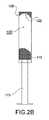
好ましくは、カートリッジ10は、外方に凸となる頭部表面37を有し、そこから針30が突出している。例えば、頭部表面37はドーム型である。そのような頭部37のドーム型構造により、小型バッグを空にすることが容易になる。実際、隅部も凹所もないので、混合物又は医薬物質の蓄積分又は滞留分が小型バッグに残留せず、小型バッグは完全に空になる。 Preferably, the
好ましくは、頭部表面37は主軸線Xに対して非対称であり、小型バッグの一方の側を起点として狭くなる。そのような構造により、カートリッジの一方の側の優先的な圧搾が可能になり、小型バッグを空にすることが容易になる。 Preferably, the
好ましくは、頭部表面37の形状は、プランジャ110の頭部113の形状、及びシリンジ100の遠位端106の底部122の形状と相補的である。そのような構造により、カートリッジの完全圧搾が可能になる。 Preferably, the shape of the
カートリッジ10にはまた、該カートリッジとシリンジ100とを機械的に係合させるようにされている係合手段が設けられている(後で詳述する)。 The
好ましくは、係合手段は、小型バッグから突出している複数の係合要素40.iを含む。 Preferably, the engaging means is a plurality of engaging elements projecting from the
例えば、カートリッジ10には、第1の小型バッグから、例えば側壁18b、18aのそれぞれから、又は前端部20’’’から突出している、該係合手段の一対の上部係合要素40.1、40.2が設けられている。 For example, the
好ましくは、カートリッジ10にはまた、第2の小型バッグから、例えば側壁22b、22aのそれぞれから、又は後端部22’’’から突出している、該係合手段の一対の下部係合要素40.3、40.4が設けられている。 Preferably, the
好ましくは、カートリッジ10にはまた、2つのチャンバ12、14を分離している隔壁16に対応して突出している、該係合手段の一対の中間係合要素40.5、40.6が設けられている。 Preferably, the
本発明はまた、図2に示す実施形態による、カートリッジ10のシリンジ100を提供する。 The present invention also provides a
シリンジ100は、例えば筒形、典型的には円筒形の本体102を含み、本体102は主に主軸線X方向に沿って、近位開口部104のある近位端103と、筒形本体102の基部108が配置されている、例えば取り付けられている、反対側の遠位端106との間に延在している。 The
シリンジ100はまた、頭部113を担持するプランジャ110を含み、プランジャを押すことにより、頭部113を近位開口部104から筒形本体に挿入し、該筒形本体102内を摺動させることができる。 The
筒形本体100は、該筒形本体102の可動壁130を開くことにより利用可能な、シリンジ100の当初の構成ではカートリッジ10を収容するようにされている、内部収容スペース120を有する。 The
シリンジ100には、カートリッジの係合手段と機械的に係合して、カートリッジ10とシリンジ100との相互配置を固定するようにされている、被係合手段が設けられている。 The
例えば、該被係合手段は、複数の貫通孔140.iを含み、カートリッジ10の該係合要素40.iは、該孔140.iに挿入されてそれらに対し固定されるようにされている。 For example, the engaged means has a plurality of through holes 140. The engaging
例えば、被係合手段は、係合要素40.iをシリンジに対し固定するために、典型的には孔140.iに挿入される係合要素40.iと係合するようにされている保持壁を含む。例えば、通常は貫通孔を閉じることができる摺動壁又は回転壁又は埋込壁が設けられており、したがって、孔140.iを閉じることにより係合要素40.iが保持される。 For example, the engaged means is the engaging
代替実施形態によると、カートリッジの外壁に固定スナップ嵌め要素が設けられ、カートリッジの係合要素40.iに設けられた相手方固定要素と共働するようにされている。 According to an alternative embodiment, a fixed snap fitting element is provided on the outer wall of the cartridge and the engaging element of the
例えば、シリンジ100には、該被係合手段の一対の上部係合孔140.1、140.2が設けられており、これらは基部108を貫通して、又は基部108近傍の領域で筒形本体102を貫通して配置され、第1の小型バッグ18の上部係合要素40.1、40.2と係合するようにされている。 For example, the
好ましくは、シリンジ100には更に、該被係合手段の一対の下部係合孔140.3、140.4が設けられており、これらは筒形本体102の近位端103近傍に配置され、第2の小型バッグ22の下部係合要素40.3、40.4と係合するようにされている。 Preferably, the
例えば、該下部貫通孔140.3、140.4のうちの少なくとも1つが可動壁130に配置されている。 For example, at least one of the lower through holes 140.3 and 140.4 is arranged in the
典型的には、シリンジ100には更に、該被係合手段の一対の中間係合孔140.5、140.6が設けられており、これらは上部孔140.1、140.2と下部孔140.3、140.4との間で筒形本体102の軸方向中間域を貫通して配置され、該中間孔140.5、140.6は、カートリッジ10の中間係合要素40.5、40.6と係合するようにされている。 Typically, the
基部108にはまた、軸方向深さを貫通している、針30を挿入するための小窓111が設けられている。 The
あるいは、基部108にはまた、基部108の周縁部から中心部へと基部の厚さを通過して延び、小窓110で終わっている、径方向チャネル112が設けられている。 Alternatively, the
チャネル112は、基部108の周縁部の、可動壁130の隅部延長部に含まれる隅部位置で開口しており、したがって針130がチャネル112内を径方向に移動して小窓110に達する間に、小型バッグ18、22をスペース120に収容することができる。 The
好ましくは、更に、針担持構成要素32を、小窓110内に形状嵌合により又は干渉させて固定することができる。 Preferably, the needle-supporting
好ましい実施形態によると、プランジャ110の頭部113はドーム型であり、スペース120に向けて凸となり好ましくは主軸線Xに対して非対称なので、カートリッジ10の一方の側が優先的に圧搾される。 According to a preferred embodiment, the
好ましくは、更に、シリンジ100は、基部108に対応して、遠位端106に底部122を有しており、底部122はスペース120に向けて凹となり、頭部113に対し相手方形状であるので、頭部113と相補的であり、カートリッジ10の圧搾を容易にする。 Preferably, further, the
本発明によるシステムの通常の働きにおいて、シリンジ100は、最初は当初構成にあり、ここでプランジャ110は退避位置にあるので、収容スペース120が筒形本体102内に画定され、カートリッジ10を収容するようにされる。 In the normal operation of the system according to the invention, the
そのようなシリンジ100の構成では、可動壁130が開いているとき、カートリッジ10が収容スペース120に挿入され、針130がチャネル112内を優先的に移動して小窓110を通って設けられ、カートリッジがカートリッジの係合手段とシリンジの被係合手段との係合によりシリンジに対し固定される。 In such a
具体的には、各係合要素40.iをそれぞれの係合孔140.iに挿入することにより、カートリッジをシリンジに対し固定する。 Specifically, each engaging
可動壁130を閉じると、システムはいつでも使用できる。 When the
プランジャ110を動かすと、頭部113が、下部係合要素40.3、40.4とそれぞれの下部係合孔140.3、140.4との係合により底部に保持されている小型バッグに押し当てられる。 When the
小型バッグの凹型底部35がプランジャ110のドーム型頭部113と共働し、チャンバを確実に完全に空にする。 The
プランジャは、頭部が底部122の近傍にくる前進位置まで進めることができ、カートリッジは頭部113と該底部122との間で完全に圧搾される(図5)。 The plunger can be advanced to a forward position where the head is near the bottom 122 and the cartridge is completely squeezed between the
プランジャの頭部113は、小型バッグのドーム型の頭部表面37を完全に圧搾し、溶液を確実に完全に放出する。 The
注射が完了すると、シリンジを開いて空のカートリッジを取り出し、別にすること、例えば廃棄物処理に投入することができる。一方シリンジは、優先的に再利用することができる。 Once the injection is complete, the syringe can be opened and the empty cartridge removed and placed in a separate, eg, waste disposal. On the other hand, the syringe can be reused preferentially.
図1の変形実施形態によると、第2の小型バッグ22の圧搾により、第2のチャンバ14内の圧力が高まり、ひいては隔壁16が破断する(図4)。 According to the modified embodiment of FIG. 1, the pressure in the
したがって、液体Lが粉末Pの入った第1のチャンバ18に流入し、その結果、注射される混合物が形成される。 Thus, the liquid L flows into the
小型バッグ22の凹型底部35がプランジャ110のドーム型頭部113と共働し、液体Lを確実に完全に排出する。 The
プランジャ110を更に押すと、第1の小型バッグ18が圧搾されて、注射される溶液Sが針30を通って流出するが、この間第2の小型バッグ18は、上部係合孔140.1、140.2に挿入され固定されている上部係合要素40.1、40.2によって、しっかりとシリンジに繋留されている。 When the
プランジャ110の頭部113は、第1の小型バッグ18のドーム型の頭部表面37を完全に圧搾し、溶液を確実に完全に放出する。 The
本発明によるカートリッジを製造するには、機械化され決まった方法の段階をたどるが、それについて次に詳述する。 Manufacture of the cartridge according to the invention follows the steps of a mechanized and fixed method, which will be described in detail below.
滅菌チャンバ200の設けられた機械で、第1の連続膜片202と第2の連続膜片204とを、互いに対向させて、準備する。 A machine provided with a
例えば、機械には、膜202、204の引き出されるロール205が設けられる。 For example, the machine is provided with
機械には、少なくとも2本の管212、214を含む供給デバイス210も設けられ、これらの管はそれぞれ、制御下の所定量の混合物構成要素、例えば所定量の粉末P及び所定量の液体Lを供給するようにされている。 The machine is also provided with a
機械には、2枚の膜を接合し、それらの間に接合端部を形成するための接合デバイス220も設けられている。 The machine is also provided with a joining
例えば、該接合デバイス220は、向い合せに置かれてその間を膜202、204が通過する溶着ヘッド222、224を含む、溶着装置を含む。 For example, the joining
第1の製造する段階では、カートリッジ10の前端部20’’’が実現され、例えば溶着ヘッド222、224を接近させて2枚の膜202、204を一体に留めることで該溶着前端部20’’’(及び場合により小型バッグの側端部20’、20’’)が形成され、開口側のあるチャンバを形成する。 In the first manufacturing stage, the front end portion 20''' of the
次に、(図11及び図12の変形実施形態の場合は)注射される溶液の供給段階を行い、又は(図1の変形実施形態の場合は)溶液の第1の構成要素の供給段階、例えば粉末Pの供給段階を行う。 Next, a feeding step of the solution to be injected (in the case of the modified embodiments of FIGS. 11 and 12) or a feeding step of the first component of the solution (in the case of the modified embodiment of FIG. 1). For example, the powder P supply stage is performed.
このために、図1の変形実施形態の場合は、第1の管212を場合により前進位置まで移動させて、所定量の粉末Pを吐出させる(図7)。 Therefore, in the case of the modified embodiment of FIG. 1, the
次に、膜202、204を順方向に送ってから、接合デバイスを再起動させて、破断可能隔壁16の形成段階を行う。 Next, the
例えば、溶着ヘッド222、224を互いに接近させ、該隔壁16を形成する膜202、204の溶着部を実現させる(図8)。 For example, the welding heads 222 and 224 are brought close to each other to realize the welding portions of the
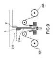
次に、膜202、204を順方向に送ってから、溶液の第2の構成要素の供給段階、例えば液体Lの供給段階を行う。 Next, the
このために、場合により第2の管214を前進位置に移動させて、所定量の液体Lを吐出させる(図9)。 For this purpose, in some cases, the
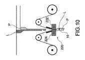
最後に、図1の変更形態でも図11の変更形態でも、場合により第2の管214又は両管212、214を後退させてから、例えば溶着ヘッド222、224を接近させて、小型バッグの後端部22’’’を形成する(図10)。 Finally, in both the modified form of FIG. 1 and the modified form of FIG. 11, the
一実施形態によると、カートリッジの係合要素40.iは、例えば適宜カットされ不要部分が適宜除去されたテープの形態として、カートリッジにより実現される膜と一体化される。 According to one embodiment, the engaging element of the
あるいは、係合要素40.iは、カートリッジの小型バッグ18、22とは別に実現され、後から例えば接着により小型バッグに取り付けられる。 Alternatively, the engaging
凹型の非対称底部35及び頭部表面37は、例えば熱成形により、又はブロー成形により、実現される。 The concave asymmetric bottom 35 and
本発明の別の目的は、シリンジとカートリッジ10とを含む注射キットである。ある変形実施形態では、注射キットは、1つのシリンジ100と、複数のカートリッジ10とを含む。 Another object of the present invention is an injection kit comprising a syringe and a
革新的なことに、本発明によるカートリッジ及びシリンジは、注射される溶液を、用量が変わらないように確実に完全に注射するという点で、従来技術の短所を克服している。 Innovatively, the cartridges and syringes according to the invention overcome the disadvantages of the prior art in that the solution to be injected is completely injected without changing the dose.
有利なことに、カートリッジの外形、基本的には内方に凹となる頭部と、シリンジの外形、基本的にはプランジャのドーム型頭部とにより、カートリッジを完全に空にすることが可能になり、用量の精度も保証される。実際、小型バッグ内に混合物又は医薬物質の蓄積分又は滞留分が残留せず、小型バッグは完全に空になる。 Advantageously, the outer shape of the cartridge, basically the inwardly concave head, and the outer shape of the syringe, basically the dome-shaped head of the plunger, allow the cartridge to be completely emptied. And the accuracy of the dose is also guaranteed. In fact, no buildup or retention of mixture or pharmaceutical substance remains in the small bag and the small bag is completely emptied.
有利なことに、カートリッジの外形、基本的には非対称湾曲部が設けられた後側部分は、プランジャの摺動を容易にし、注射物質の放出を容易にするのに役立つ。 Advantageously, the outer shape of the cartridge, essentially the rear portion provided with the asymmetrical bend, helps facilitate the sliding of the plunger and facilitates the release of the injectable material.
有利なことに、本発明によるカートリッジ、シリンジ、及び方法はまた、医薬混合物の注射システムの製造コストを大幅に低下させることができる。実際、薄膜片によってカートリッジを実装するので、液体構成要素又は混合物構成要素を入れるガラス製バイアルの必要性がなくなる。 Advantageously, the cartridges, syringes, and methods according to the invention can also significantly reduce the cost of manufacturing an injection system for pharmaceutical mixtures. In fact, since the cartridge is mounted by a piece of thin film, there is no need for a glass vial to hold the liquid or mixture components.
有利なことに、更に、定常的製造により製造量を大幅に増加できるので、システムのコストが更に低下する。 Advantageously, the cost of the system is further reduced because the production volume can be significantly increased by routine production.
有利なことに、更に、このシステムではシリンジが再利用できるので、最終ユーザーにとっても低コストとなる。 Advantageously, the system also allows the syringe to be reused, resulting in lower cost for the end user.
別の有利な態様によると、本発明による二重チャンバのカートリッジを有するシステムの使用により、混合物の構成要素の投薬及び混合の手違いの可能性が排除されるので、特に患者にとって特に安全である。 According to another advantageous embodiment, the use of a system with a double chamber cartridge according to the invention is particularly safe, especially for patients, as it eliminates the possibility of erroneous dosing and mixing of the components of the mixture.
更に、このシステムの使用は、カートリッジがシリンジに対して定位置にしっかり保持されているので、特に簡易で安全である。 Moreover, the use of this system is particularly simple and safe as the cartridge is held firmly in place with respect to the syringe.
付随する要件を満たすために、当業者がカートリッジ、シリンジ、及び上述の方法に変形を加え得ることは明らかであり、そうした変形はすべて、以下の特許請求の範囲で定められる保護範囲内とする。 It will be apparent that those skilled in the art may make modifications to the cartridges, syringes, and methods described above to meet the accompanying requirements, all of which are within the scope of the claims set forth below.
Claims (18)
Translated fromJapanese薄膜壁で構成され、
主軸線(X)方向に延在し、
医薬物質(S、P、L)を含むチャンバ(12、14)を囲む可撓性のある小型バッグ(18、22)を少なくとも一つ含み、
外方向に凸となるドーム型の頭部表面(37)を有し、
前記頭部表面(37)は、主軸線(X)に対して非対称であり、前記小型バッグの一方の側を起点として狭くなっている、
薬液注射用のカートリッジ(10)。A cartridge (10) for injecting a drug when contained in a syringe.
It is composedof a thin filmwall,
Extending in the main axis (X) direction,
Containing at least one small flexiblebag (18, 22)surrounding the chamber (12, 14)containing the pharmaceutical substance (S, P, L).
It has a dome-shaped head surface (37) that is convex outward, and has a dome-shaped head surface (37).
The head surface (37) is asymmetric with respect to the main axis (X) and is narrowed starting from one side of the small bag.
Cartridge for chemical injection (10).
ドーム型であって前記スペース(120)に向けて凸で、前記主軸線(X)に対して非対称の頭部(113)が設けられたプランジャ(110)と、
前記本体(102)に設けられて、前記スペース(120)に向けて凹型になっている固定底部(122)と、
を含み、
前記固定底部(122)は、前記プランジャの前記頭部(113)の反対側にあり、前記頭部(113)の凸形状と相補的な凹型の形状になっている、
シリンジ(100)。A main body (102) extending along the main axis (X) direction and provided with a storage space (120) for storing the cartridge (10).
A plunger (110) having adome shape, convex toward the space (120), and provided with a head (113) asymmetric with respect to the main axis (X).
A fixed bottom portion (122) provided on the main body (102) and concave toward the space (120).
Including
The fixed bottom (122) is on the opposite side of the plunger's head (113) and has a concave shape complementary to the convex shape of the head (113).
Syringe(100) .
第1の連続膜片(202)と第2の連続膜片(204)とを対向させて配置し、準備するステップと、
前記2枚の膜(202、204)を接合端部に沿って接合することにより、前記カートリッジ(10)の、上部が開口しているチャンバ(12)を実現するステップと、
所定量の医薬物質(S、P、L)を前記開口チャンバ(12)に供給するステップと、
前記チャンバ(12)を後端部によって閉じるステップと、
熱成形又はブロー成形により、外方に向けてドーム型となる凸型の頭部表面(37)を実現するステップと、
熱成形又はブロー成形により、凹型の非対称な底部(35)を実現するステップと、
を含む方法。A method for manufacturing a cartridge (10) for injection of a chemical solution (S).
A step of arranging and preparing the first continuous film piece (202) and the second continuous film piece (204) so as to face each other,
A step of realizing a chamber (12) in which the upper part of the cartridge (10) is open by joining the two films (202, 204) along the joining end portion.
A step of supplying a predetermined amount of a pharmaceutical substance (S, P, L) to the opening chamber (12), and
The step of closing the chamber (12) by the rear end,
A step of realizing a convex head surface (37) that becomes a dome shape outward by thermoforming or blow molding, and
A step to achieve a concave asymmetric bottom (35) by thermoforming or blow molding,
Howto include.
前記チャンバを閉じるステップは、
前記カートリッジ(10)の、上部が開口している第2のチャンバ(14)を実現することであって、前記2枚の膜(202、204)を更なる接合端部に沿って接合して、前記第1のチャンバ(12)の前記上部を閉じ、前記第1のチャンバ(12)を前記第2のチャンバ(14)から分離する、前記更なる接合端部のうちの1つで構成される破断可能隔壁(16)を形成することによって、実現することと、
溶液(S)の所定量の第2の構成要素(L)を前記第2の開口チャンバ(14)に供給することと、
前記第2のチャンバ(14)を後端部(22’’’)によって閉じることと、
を備えている、請求項17に記載の方法。The step of supplying the pharmaceutical substance (S, P, L) comprises supplying a predetermined amount of the first component (P) of the solution (S) to the first opening chamber (12).
The step of closing the chamber is
A second chamber (14) of the cartridge (10) with an open top is realized by joining the two membranes (202, 204) along a further joint end. Consists of one of the additional junction ends, which closes the top of the first chamber (12) and separates the first chamber (12) from the second chamber (14). What can be achieved by forming a breakable partition wall (16)
Supplying a predetermined amount of the second component (L) of the solution (S) to the second opening chamber (14),
Closing the second chamber (14) by the rear end (22''') and
17. The method of claim 17.
Applications Claiming Priority (3)
| Application Number | Priority Date | Filing Date | Title |
|---|---|---|---|
| IT102016000013599 | 2016-02-10 | ||
| ITUB2016A000615AITUB20160615A1 (en) | 2016-02-10 | 2016-02-10 | Cartridge and syringe for injection of a pharmaceutical solution and method for cartridge production |
| PCT/IB2017/050152WO2017137854A1 (en) | 2016-02-10 | 2017-01-12 | Cartridge with flexible bag for injecting a pharmaceutical solution and method for manufacturing the cartridge |
Publications (2)
| Publication Number | Publication Date |
|---|---|
| JP2019504704A JP2019504704A (en) | 2019-02-21 |
| JP6932707B2true JP6932707B2 (en) | 2021-09-08 |
Family
ID=55969277
Family Applications (1)
| Application Number | Title | Priority Date | Filing Date |
|---|---|---|---|
| JP2018541658AActiveJP6932707B2 (en) | 2016-02-10 | 2017-01-12 | A cartridge for chemical injection having a flexible bag, and a method for manufacturing the cartridge. |
Country Status (17)
| Country | Link |
|---|---|
| US (1) | US11097054B2 (en) |
| EP (1) | EP3413861B1 (en) |
| JP (1) | JP6932707B2 (en) |
| CN (1) | CN108601703A (en) |
| AU (1) | AU2017218694A1 (en) |
| BR (1) | BR112018016385A2 (en) |
| CA (1) | CA3013545A1 (en) |
| EA (1) | EA036241B1 (en) |
| ES (1) | ES2772815T3 (en) |
| HK (1) | HK1256120A1 (en) |
| IT (1) | ITUB20160615A1 (en) |
| LT (1) | LT3413861T (en) |
| PL (1) | PL3413861T3 (en) |
| PT (1) | PT3413861T (en) |
| SM (1) | SMT202000029T1 (en) |
| WO (1) | WO2017137854A1 (en) |
| ZA (1) | ZA201805291B (en) |
Families Citing this family (1)
| Publication number | Priority date | Publication date | Assignee | Title |
|---|---|---|---|---|
| IT201800009131A1 (en) | 2018-10-03 | 2020-04-03 | Orofino Pharmaceuticals Group Srl | Deformable cartridge for injection device |
Family Cites Families (15)
| Publication number | Priority date | Publication date | Assignee | Title |
|---|---|---|---|---|
| GB1583157A (en)* | 1976-05-07 | 1981-01-21 | Kenova Ab | Syringes |
| GB1573514A (en)* | 1977-05-09 | 1980-08-28 | Helinos Ab | Container and device for emptying the container |
| US4312344A (en)* | 1980-04-03 | 1982-01-26 | Kenova Ab | Syringe |
| JP2001299912A (en)* | 2000-02-17 | 2001-10-30 | Koriryo Yugenkoshi | Injection kit and injection apparatus |
| US20010047162A1 (en)* | 2000-02-17 | 2001-11-29 | Yasumi Yugari | Injection kit and injection device |
| US20070191780A1 (en)* | 2006-02-16 | 2007-08-16 | Pankaj Modi | Drug delivery device |
| CN101389550B (en)* | 2006-02-21 | 2011-04-20 | 药物混合系统股份公司 | Device for piercing film |
| FR2933307B1 (en)* | 2008-07-07 | 2012-08-03 | Jean Paul Cahen | DEVICE FOR INJECTING A MEDICAL USE FLUID |
| GB0821492D0 (en)* | 2008-11-25 | 2008-12-31 | Team Holdings Uk Ltd | Integrated auto-injector cartridge system |
| WO2011068130A1 (en)* | 2009-12-02 | 2011-06-09 | テルモ株式会社 | Pre-filled syringe |
| JP2011212184A (en)* | 2010-03-31 | 2011-10-27 | Terumo Corp | Prefilled syringe |
| JP2012029723A (en)* | 2010-07-28 | 2012-02-16 | Terumo Corp | Injection needle assembly and drug injection apparatus |
| US10046106B2 (en)* | 2010-10-25 | 2018-08-14 | Bayer Healthcare Llc | Bladder syringe fluid delivery system |
| US9498570B2 (en)* | 2010-10-25 | 2016-11-22 | Bayer Healthcare Llc | Bladder syringe fluid delivery system |
| US9408972B2 (en)* | 2011-08-02 | 2016-08-09 | Pharmajet, Inc. | Needle-free injection device |
- 2016
- 2016-02-10ITITUB2016A000615Apatent/ITUB20160615A1/enunknown
- 2017
- 2017-01-12SMSM20200029Tpatent/SMT202000029T1/enunknown
- 2017-01-12CACA3013545Apatent/CA3013545A1/ennot_activeAbandoned
- 2017-01-12USUS16/076,908patent/US11097054B2/ennot_activeExpired - Fee Related
- 2017-01-12AUAU2017218694Apatent/AU2017218694A1/ennot_activeAbandoned
- 2017-01-12LTLTEP17706303.9Tpatent/LT3413861T/enunknown
- 2017-01-12JPJP2018541658Apatent/JP6932707B2/enactiveActive
- 2017-01-12CNCN201780010648.9Apatent/CN108601703A/enactivePending
- 2017-01-12EPEP17706303.9Apatent/EP3413861B1/enactiveActive
- 2017-01-12PTPT177063039Tpatent/PT3413861T/enunknown
- 2017-01-12ESES17706303Tpatent/ES2772815T3/enactiveActive
- 2017-01-12BRBR112018016385-6Apatent/BR112018016385A2/ennot_activeApplication Discontinuation
- 2017-01-12HKHK18115198.8Apatent/HK1256120A1/enunknown
- 2017-01-12PLPL17706303Tpatent/PL3413861T3/enunknown
- 2017-01-12EAEA201891574Apatent/EA036241B1/ennot_activeIP Right Cessation
- 2017-01-12WOPCT/IB2017/050152patent/WO2017137854A1/ennot_activeCeased
- 2018
- 2018-08-10ZAZA2018/05291Apatent/ZA201805291B/enunknown
Also Published As
| Publication number | Publication date |
|---|---|
| PL3413861T3 (en) | 2020-05-18 |
| CA3013545A1 (en) | 2017-08-17 |
| SMT202000029T1 (en) | 2020-03-13 |
| ZA201805291B (en) | 2019-05-29 |
| JP2019504704A (en) | 2019-02-21 |
| US11097054B2 (en) | 2021-08-24 |
| US20190046730A1 (en) | 2019-02-14 |
| ES2772815T3 (en) | 2020-07-08 |
| EA201891574A1 (en) | 2019-01-31 |
| EP3413861B1 (en) | 2019-10-16 |
| LT3413861T (en) | 2020-01-27 |
| BR112018016385A2 (en) | 2018-12-18 |
| EA036241B1 (en) | 2020-10-16 |
| HK1256120A1 (en) | 2019-09-13 |
| EP3413861A1 (en) | 2018-12-19 |
| AU2017218694A1 (en) | 2018-09-13 |
| ITUB20160615A1 (en) | 2017-08-10 |
| PT3413861T (en) | 2020-01-21 |
| CN108601703A (en) | 2018-09-28 |
| WO2017137854A1 (en) | 2017-08-17 |
Similar Documents
| Publication | Publication Date | Title |
|---|---|---|
| JP5677846B2 (en) | Cartridge for powder and liquid drugs | |
| US20180072480A1 (en) | Packaged products, inserts and compartments for aseptic mixing of substances, along with methods for use therewith | |
| JP4838304B2 (en) | Container with hollow needle | |
| US20150374440A1 (en) | Shipping Container Integrating A Sharps Disposal Container With A New Product Storage Container | |
| UA66342C2 (en) | Two-chamber container for propellent-free metered aerosols | |
| JP2016527048A (en) | Intermediate product for manufacturing pre-filled dual chamber syringe or pre-filled dual chamber cartridge and manufacturing method for manufacturing this intermediate product | |
| JP6932707B2 (en) | A cartridge for chemical injection having a flexible bag, and a method for manufacturing the cartridge. | |
| JP5594687B2 (en) | Drug discharge tool and multi-chamber container using drug discharge tool | |
| KR20190013829A (en) | Two-part plastic blank set | |
| US2771071A (en) | Ampulla structure | |
| US10940091B2 (en) | Oral medicine dispensing system | |
| KR100973738B1 (en) | A needle unified medicine liquid capsule | |
| JP5542403B2 (en) | Small container | |
| WO2013047029A1 (en) | Medical container | |
| TW201019930A (en) | Receptacle and method for storing and supplying a liquid and a liquid medical preparation | |
| JP6108359B2 (en) | Vials | |
| JP2000060970A (en) | Medicine contained syringe | |
| HK1122489B (en) | Container with a hollow needle | |
| KR20120083948A (en) | Medicine liquid capsule |
Legal Events
| Date | Code | Title | Description |
|---|---|---|---|
| A521 | Request for written amendment filed | Free format text:JAPANESE INTERMEDIATE CODE: A821 Effective date:20180919 Free format text:JAPANESE INTERMEDIATE CODE: A523 Effective date:20180919 | |
| A621 | Written request for application examination | Free format text:JAPANESE INTERMEDIATE CODE: A621 Effective date:20191115 | |
| A977 | Report on retrieval | Free format text:JAPANESE INTERMEDIATE CODE: A971007 Effective date:20201118 | |
| A131 | Notification of reasons for refusal | Free format text:JAPANESE INTERMEDIATE CODE: A131 Effective date:20201201 | |
| A521 | Request for written amendment filed | Free format text:JAPANESE INTERMEDIATE CODE: A523 Effective date:20210301 | |
| TRDD | Decision of grant or rejection written | ||
| A01 | Written decision to grant a patent or to grant a registration (utility model) | Free format text:JAPANESE INTERMEDIATE CODE: A01 Effective date:20210803 | |
| A61 | First payment of annual fees (during grant procedure) | Free format text:JAPANESE INTERMEDIATE CODE: A61 Effective date:20210818 | |
| R150 | Certificate of patent or registration of utility model | Ref document number:6932707 Country of ref document:JP Free format text:JAPANESE INTERMEDIATE CODE: R150 | |
| R250 | Receipt of annual fees | Free format text:JAPANESE INTERMEDIATE CODE: R250 |