JP6932648B2 - Excavator - Google Patents
ExcavatorDownload PDFInfo
- Publication number
- JP6932648B2 JP6932648B2JP2017559233AJP2017559233AJP6932648B2JP 6932648 B2JP6932648 B2JP 6932648B2JP 2017559233 AJP2017559233 AJP 2017559233AJP 2017559233 AJP2017559233 AJP 2017559233AJP 6932648 B2JP6932648 B2JP 6932648B2
- Authority
- JP
- Japan
- Prior art keywords
- work
- excavator
- hydraulic
- flow rate
- hydraulic oil
- Prior art date
- Legal status (The legal status is an assumption and is not a legal conclusion. Google has not performed a legal analysis and makes no representation as to the accuracy of the status listed.)
- Active
Links
- 239000010720hydraulic oilSubstances0.000claimsdescription59
- 230000008859changeEffects0.000claimsdescription5
- 238000003384imaging methodMethods0.000claimsdescription4
- 238000005259measurementMethods0.000claims1
- 230000007423decreaseEffects0.000description12
- 239000000463materialSubstances0.000description11
- 238000000034methodMethods0.000description11
- 239000004575stoneSubstances0.000description11
- 230000008569processEffects0.000description10
- 238000004891communicationMethods0.000description6
- 238000010586diagramMethods0.000description6
- 230000005540biological transmissionEffects0.000description5
- 230000004044responseEffects0.000description4
- 230000001133accelerationEffects0.000description3
- 238000010276constructionMethods0.000description3
- 230000006870functionEffects0.000description3
- 239000003921oilSubstances0.000description3
- 238000009412basement excavationMethods0.000description2
- 230000003247decreasing effectEffects0.000description2
- 238000007599dischargingMethods0.000description2
- 239000000446fuelSubstances0.000description2
- 230000007246mechanismEffects0.000description2
- 239000002184metalSubstances0.000description2
- 239000002699waste materialSubstances0.000description2
- CWYNVVGOOAEACU-UHFFFAOYSA-NFe2+Chemical compound[Fe+2]CWYNVVGOOAEACU-UHFFFAOYSA-N0.000description1
- 240000007594Oryza sativaSpecies0.000description1
- 235000007164Oryza sativaNutrition0.000description1
- 238000003197gene knockdownMethods0.000description1
- 239000004973liquid crystal related substanceSubstances0.000description1
- 239000012528membraneSubstances0.000description1
- 238000012986modificationMethods0.000description1
- 230000004048modificationEffects0.000description1
- 235000009566riceNutrition0.000description1
- 239000004065semiconductorSubstances0.000description1
- 238000001179sorption measurementMethods0.000description1
- 238000006467substitution reactionMethods0.000description1
Images


Classifications
- E—FIXED CONSTRUCTIONS
- E02—HYDRAULIC ENGINEERING; FOUNDATIONS; SOIL SHIFTING
- E02F—DREDGING; SOIL-SHIFTING
- E02F9/00—Component parts of dredgers or soil-shifting machines, not restricted to one of the kinds covered by groups E02F3/00 - E02F7/00
- E02F9/20—Drives; Control devices
- E02F9/22—Hydraulic or pneumatic drives
- E02F9/2264—Arrangements or adaptations of elements for hydraulic drives
- E02F9/2271—Actuators and supports therefor and protection therefor
- E—FIXED CONSTRUCTIONS
- E02—HYDRAULIC ENGINEERING; FOUNDATIONS; SOIL SHIFTING
- E02F—DREDGING; SOIL-SHIFTING
- E02F9/00—Component parts of dredgers or soil-shifting machines, not restricted to one of the kinds covered by groups E02F3/00 - E02F7/00
- E02F9/20—Drives; Control devices
- E02F9/22—Hydraulic or pneumatic drives
- E02F9/2246—Control of prime movers, e.g. depending on the hydraulic load of work tools
- E—FIXED CONSTRUCTIONS
- E02—HYDRAULIC ENGINEERING; FOUNDATIONS; SOIL SHIFTING
- E02F—DREDGING; SOIL-SHIFTING
- E02F9/00—Component parts of dredgers or soil-shifting machines, not restricted to one of the kinds covered by groups E02F3/00 - E02F7/00
- E02F9/20—Drives; Control devices
- E02F9/22—Hydraulic or pneumatic drives
- E02F9/2203—Arrangements for controlling the attitude of actuators, e.g. speed, floating function
- E—FIXED CONSTRUCTIONS
- E02—HYDRAULIC ENGINEERING; FOUNDATIONS; SOIL SHIFTING
- E02F—DREDGING; SOIL-SHIFTING
- E02F9/00—Component parts of dredgers or soil-shifting machines, not restricted to one of the kinds covered by groups E02F3/00 - E02F7/00
- E02F9/20—Drives; Control devices
- E02F9/22—Hydraulic or pneumatic drives
- E02F9/2221—Control of flow rate; Load sensing arrangements
- E02F9/2232—Control of flow rate; Load sensing arrangements using one or more variable displacement pumps
- E02F9/2235—Control of flow rate; Load sensing arrangements using one or more variable displacement pumps including an electronic controller
- E—FIXED CONSTRUCTIONS
- E02—HYDRAULIC ENGINEERING; FOUNDATIONS; SOIL SHIFTING
- E02F—DREDGING; SOIL-SHIFTING
- E02F9/00—Component parts of dredgers or soil-shifting machines, not restricted to one of the kinds covered by groups E02F3/00 - E02F7/00
- E02F9/20—Drives; Control devices
- E02F9/22—Hydraulic or pneumatic drives
- E02F9/2278—Hydraulic circuits
- E02F9/2285—Pilot-operated systems
- E—FIXED CONSTRUCTIONS
- E02—HYDRAULIC ENGINEERING; FOUNDATIONS; SOIL SHIFTING
- E02F—DREDGING; SOIL-SHIFTING
- E02F9/00—Component parts of dredgers or soil-shifting machines, not restricted to one of the kinds covered by groups E02F3/00 - E02F7/00
- E02F9/20—Drives; Control devices
- E02F9/22—Hydraulic or pneumatic drives
- E02F9/2278—Hydraulic circuits
- E02F9/2292—Systems with two or more pumps
- E—FIXED CONSTRUCTIONS
- E02—HYDRAULIC ENGINEERING; FOUNDATIONS; SOIL SHIFTING
- E02F—DREDGING; SOIL-SHIFTING
- E02F9/00—Component parts of dredgers or soil-shifting machines, not restricted to one of the kinds covered by groups E02F3/00 - E02F7/00
- E02F9/20—Drives; Control devices
- E02F9/22—Hydraulic or pneumatic drives
- E02F9/2278—Hydraulic circuits
- E02F9/2296—Systems with a variable displacement pump
- E—FIXED CONSTRUCTIONS
- E02—HYDRAULIC ENGINEERING; FOUNDATIONS; SOIL SHIFTING
- E02F—DREDGING; SOIL-SHIFTING
- E02F9/00—Component parts of dredgers or soil-shifting machines, not restricted to one of the kinds covered by groups E02F3/00 - E02F7/00
- E02F9/26—Indicating devices
- E02F9/261—Surveying the work-site to be treated
- E—FIXED CONSTRUCTIONS
- E02—HYDRAULIC ENGINEERING; FOUNDATIONS; SOIL SHIFTING
- E02F—DREDGING; SOIL-SHIFTING
- E02F9/00—Component parts of dredgers or soil-shifting machines, not restricted to one of the kinds covered by groups E02F3/00 - E02F7/00
- E02F9/26—Indicating devices
- E02F9/264—Sensors and their calibration for indicating the position of the work tool
- E02F9/265—Sensors and their calibration for indicating the position of the work tool with follow-up actions (e.g. control signals sent to actuate the work tool)
- E—FIXED CONSTRUCTIONS
- E02—HYDRAULIC ENGINEERING; FOUNDATIONS; SOIL SHIFTING
- E02F—DREDGING; SOIL-SHIFTING
- E02F9/00—Component parts of dredgers or soil-shifting machines, not restricted to one of the kinds covered by groups E02F3/00 - E02F7/00
- E02F9/20—Drives; Control devices
- E02F9/2025—Particular purposes of control systems not otherwise provided for
- E02F9/2033—Limiting the movement of frames or implements, e.g. to avoid collision between implements and the cabin
Landscapes
- Engineering & Computer Science (AREA)
- Mining & Mineral Resources (AREA)
- Civil Engineering (AREA)
- General Engineering & Computer Science (AREA)
- Structural Engineering (AREA)
- Physics & Mathematics (AREA)
- Fluid Mechanics (AREA)
- Operation Control Of Excavators (AREA)
- Component Parts Of Construction Machinery (AREA)
- Closed-Circuit Television Systems (AREA)
- Image Analysis (AREA)
Description
Translated fromJapanese本発明は、ショベルに関する。 The present invention relates to excavators.
複数の作業モードを備え、選択された作業モードに基づいてエンジンの回転数等を制御する建設機械の制御装置が知られている(例えば、特許文献1参照)。 A control device for a construction machine having a plurality of work modes and controlling an engine speed or the like based on a selected work mode is known (see, for example, Patent Document 1).
建設機械であるショベルの作業負荷は、作業の内容によって異なる。例えば同じような積み込み作業であっても、積み込みを行う対象物によって作業負荷は異なる。操作者が作業に応じて常に最適な作業モードを選択するとは限らない。 The workload of excavators, which are construction machines, varies depending on the content of the work. For example, even in the same loading work, the workload differs depending on the object to be loaded. The operator does not always select the optimum work mode according to the work.
このため、操作者が選択した作業モードに基づくエンジン回転数や油圧ポンプの設定等では、作業の内容によってはミスマッチな設定となり、不必要にエンジン回転数を上げて燃費を悪化させたり、作業に必要な出力馬力を得られなかったりする場合がある。 For this reason, the engine speed and hydraulic pump settings based on the work mode selected by the operator may be mismatched depending on the work content, and the engine speed may be unnecessarily increased to worsen fuel efficiency or work. It may not be possible to obtain the required output horsepower.
本発明は上記に鑑みてなされたものであって、作業現場に応じて油圧アクチュエータの制御を調整することが可能なショベルを提供することを目的とする。
The present invention has been made in view of the above, and an object of the present invention is to provide an excavator capableof adjusting the control of a hydraulic actuator according toa work site.
本発明の一態様に係るショベルによれば、走行動作を行う下部走行体と、前記下部走行体に旋回自在に搭載される上部旋回体と、エンジンによって駆動される油圧ポンプが吐出する作動油によって作動する複数の油圧アクチュエータと、作業現場の種別を認識して作業を判定する判定部と、前記判定部による判定結果に基づいて、前記エンジン、前記油圧ポンプ、及び、前記複数の油圧アクチュエータのうち少なくとも何れか一つを制御する制御部と、を有する。
According to the excavator according to one aspect of the present invention, the lower traveling body that performs the traveling operation, the upper rotating body that is rotatably mounted on the lower traveling body, and the hydraulic oil discharged by the hydraulic pump driven by the engine are used. Of the engine, the hydraulic pump, and the plurality of hydraulic actuators, based on the plurality of operating hydraulic actuators, thedetermination unit that recognizes the type of the work site and determines the work, and the determination result by the determination unit. It has a control unit that controls at least one of them.
本発明の実施形態によれば、作業現場に応じて油圧アクチュエータの制御を調整することが可能なショベルが提供される。
According to the embodiment of the present invention, there is provided an excavator capableof adjusting the control of the hydraulic actuatoraccording to the work site.
以下、図面を参照して発明を実施するための形態について説明する。各図面において、同一構成部分には同一符号を付し、重複した説明を省略する場合がある。 Hereinafter, modes for carrying out the invention will be described with reference to the drawings. In each drawing, the same components may be designated by the same reference numerals and duplicate description may be omitted.
図1は、実施例に係るショベルを例示する側面図である。図2は、実施例に係るショベルを例示する上面図である。図2には、カメラ、マシンガイダンス装置、及び表示装置の接続関係が示されている。 FIG. 1 is a side view illustrating an excavator according to an embodiment. FIG. 2 is a top view illustrating the excavator according to the embodiment. FIG. 2 shows the connection relationship between the camera, the machine guidance device, and the display device.
ショベルの下部走行体1には旋回機構2を介して上部旋回体3が旋回可能に搭載されている。上部旋回体3にはブーム4が取り付けられている。ブーム4の先端にはアーム5が取り付けられ、アーム5の先端にはエンドアタッチメントとしてのバケット6が取り付けられている。 An upper
ブーム4、アーム5、及びバケット6は、アタッチメントの一例として掘削アタッチメントを構成し、ブームシリンダ7、アームシリンダ8、及びバケットシリンダ9によりそれぞれ油圧駆動される。ブーム4にはブーム角度センサS1が取り付けられ、アーム5にはアーム角度センサS2が取り付けられ、バケット6にはバケット角度センサS3が取り付けられている。 The
ブーム角度センサS1は、ブーム4の回動角度を検出する。本実施例では、ブーム角度センサS1は水平面に対する傾斜を検出して上部旋回体3に対するブーム4の回動角度を検出する加速度センサである。 The boom angle sensor S1 detects the rotation angle of the
アーム角度センサS2はアーム5の回動角度を検出する。本実施例では、アーム角度センサS2は水平面に対する傾斜を検出してブーム4に対するアーム5の回動角度を検出する加速度センサである。 The arm angle sensor S2 detects the rotation angle of the
バケット角度センサS3はバケット6の回動角度を検出する。本実施例では、バケット角度センサS3は水平面に対する傾斜を検出してアーム5に対するバケット6の回動角度を検出する加速度センサである。 The bucket angle sensor S3 detects the rotation angle of the
ブーム角度センサS1、アーム角度センサS2、及びバケット角度センサS3は、可変抵抗器を利用したポテンショメータ、対応する油圧シリンダのストローク量を検出するストロークセンサ、連結ピン回りの回動角度を検出するロータリエンコーダ等であってもよい。 The boom angle sensor S1, the arm angle sensor S2, and the bucket angle sensor S3 are a potentiometer using a variable resistor, a stroke sensor that detects the stroke amount of the corresponding hydraulic cylinder, and a rotary encoder that detects the rotation angle around the connecting pin. And so on.
上部旋回体3には、キャビン10が設けられ、エンジン11等の動力源が搭載されている。上部旋回体3には、左側方カメラS4、図1には不図示の右側方カメラS5、及び後方カメラS6が取り付けられている。上部旋回体3には、通信装置S7及び測位装置S8が取り付けられている。上部旋回体3には、水平面に対する傾斜角を検出する機体傾斜センサや、旋回角速度を検出する旋回角速度センサ等が取り付けられてもよい。 The
左側方カメラS4は、運転席に座った操作者から見て上部旋回体3の左側に取り付けられ、ショベルの左側周辺の画像を取得する撮像装置である。右側方カメラS5は、運転席に座った操作者から見て上部旋回体3の右側に取り付けられ、ショベルの右側周辺の画像を取得する撮像装置である。後方カメラS6は、上部旋回体3の後方に取り付けられ、ショベルの後方周辺の画像を取得する撮像装置である。 The left-side camera S4 is an imaging device attached to the left side of the upper
通信装置S7は、ショベルと外部との間の通信を制御する装置である。本実施例では、通信装置S7は、GNSS(Global Navigation Satellite System)測量システムとショベルとの間の無線通信を制御する。具体的には、通信装置S7は、例えば1日1回の頻度で、ショベルの作業を開始する際に作業現場の地形情報を取得する。GNSS測量システムは、例えばネットワーク型RTK−GNSS測位方式を採用する。 The communication device S7 is a device that controls communication between the shovel and the outside. In this embodiment, the communication device S7 controls wireless communication between the GNSS (Global Navigation Satellite System) survey system and the excavator. Specifically, the communication device S7 acquires topographical information on the work site when the excavator work is started, for example, once a day. The GNSS surveying system employs, for example, a network-type RTK-GNSS positioning method.
測位装置S8は、ショベルの位置及び向きを測定する装置である。本実施例では、測位装置S8は、電子コンパスを組み込んだGNSS受信機であり、ショベルの存在位置の緯度、経度、高度を測定し、且つ、ショベルの向きを測定する。測位装置S8は、例えばGPS等によりショベルの現在位置情報を取得してもよい。 The positioning device S8 is a device that measures the position and orientation of the excavator. In this embodiment, the positioning device S8 is a GNSS receiver incorporating an electronic compass, measures the latitude, longitude, and altitude of the position where the excavator exists, and measures the direction of the excavator. The positioning device S8 may acquire the current position information of the excavator by, for example, GPS or the like.
キャビン10内には、入力装置D1、音声出力装置D2、表示装置D3、記憶装置D4、ゲートロックレバーD5、コントローラ30、及びマシンガイダンス装置50が設置されている。 An input device D1, an audio output device D2, a display device D3, a storage device D4, a gate lock lever D5, a
コントローラ30は、ショベルの駆動制御を行う主制御部として機能する。本実施例では、コントローラ30は、CPU及び内部メモリを含む演算処理装置で構成されている。コントローラ30の各種機能は、CPUが内部メモリに格納されたプログラムを実行することで実現される。 The
マシンガイダンス装置50は、ショベルの操作をガイドする。マシンガイダンス装置50は、例えば、操作者が設定した目標施工面とバケット6の先端(爪先)位置との鉛直方向における距離を視覚的に且つ聴覚的に報知することで、操作者にショベルの操作をガイドする。マシンガイダンス装置50は、その距離を視覚的に操作者に知らせるのみであってもよく、聴覚的に操作者に知らせるのみであってもよい。 The
マシンガイダンス装置50は、コントローラ30と同様、CPU及び内部メモリを含む演算処理装置で構成される。マシンガイダンス装置50の各種機能はCPUが内部メモリに格納されたプログラムを実行することで実現される。マシンガイダンス装置50は、コントローラ30とは別個に設けられてもよく、或いは、コントローラ30に組み込まれていてもよい。 Like the
入力装置D1は、ショベルの操作者がマシンガイダンス装置50に各種情報を入力するための装置である。本実施例では、入力装置D1は、表示装置D3の周囲に取り付けられるメンブレンスイッチである。入力装置D1としてタッチパネル等が用いられてもよい。 The input device D1 is a device for the shovel operator to input various information to the
音声出力装置D2は、マシンガイダンス装置50からの音声出力指令に応じて各種音声情報を出力する。本実施例では、音声出力装置D2として、マシンガイダンス装置50に接続されている車載スピーカが利用される。音声出力装置D2として、ブザー等の警報器が利用されてもよい。 The voice output device D2 outputs various voice information in response to a voice output command from the
表示装置D3は、マシンガイダンス装置50からの指令に応じて各種画像情報を出力する。本実施例では、表示装置D3として、マシンガイダンス装置50に接続されている車載液晶ディスプレイが利用される。 The display device D3 outputs various image information in response to a command from the
記憶装置D4は、各種情報を記憶するための装置である。本実施例では、記憶装置D4として、半導体メモリ等の不揮発性記憶媒体が用いられる。記憶装置D4は、マシンガイダンス装置50等が出力する各種情報等を記憶する。 The storage device D4 is a device for storing various types of information. In this embodiment, a non-volatile storage medium such as a semiconductor memory is used as the storage device D4. The storage device D4 stores various information and the like output by the
ゲートロックレバーD5は、ショベルが誤って操作されるのを防止する機構である。本実施例では、ゲートロックレバーD5は、キャビン10のドアと運転席との間に配置される。キャビン10から操作者が退出できないようにゲートロックレバーD5が引き上げられた場合に、各種操作装置は操作可能となる。一方、キャビン10から操作者が退出できるようにゲートロックレバーD5が押し下げられた場合には、各種操作装置は操作不能となる。 The gate lock lever D5 is a mechanism for preventing the excavator from being erroneously operated. In this embodiment, the gate lock lever D5 is arranged between the door of the
図2に示すように、左側方カメラS4、右側方カメラS5、及び後方カメラS6は、伝送媒体CB1を介して、キャビン10内に設置されたマシンガイダンス装置50に接続されている。マシンガイダンス装置50は、伝送媒体CB2を介して、キャビン10内の右斜めピラーに取り付けられている表示装置D3に接続されている。 As shown in FIG. 2, the left side camera S4, the right side camera S5, and the rear camera S6 are connected to the
伝送媒体CB1は、上部旋回体3のハウジングの内壁に沿って配置されている。伝送媒体CB2は、キャビン10の内壁に沿って配置されている。伝送媒体CB1、CB2は、例えば、同軸ケーブル等の任意のケーブルで構成される。 The transmission medium CB1 is arranged along the inner wall of the housing of the
左側方カメラS4、右側方カメラS5、後方カメラS6、マシンガイダンス装置50、及び表示装置D3は、それぞれ電源ケーブルPC1、PC2、PC3、PC4、PC5を介して蓄電池70に接続されている。 The left side camera S4, the right side camera S5, the rear camera S6, the
図3は、実施例に係るショベルに搭載される油圧システムを例示する図である。図3において、機械的動力系は二重線、高圧油圧ラインは実線、パイロットラインは破線、電気駆動・制御系は点線で示されている。 FIG. 3 is a diagram illustrating a hydraulic system mounted on the excavator according to the embodiment. In FIG. 3, the mechanical power system is shown by a double line, the high-pressure hydraulic line is shown by a solid line, the pilot line is shown by a broken line, and the electric drive / control system is shown by a dotted line.
ショベルには、油圧アクチュエータとして、ブームシリンダ7、アームシリンダ8、バケットシリンダ9、走行用油圧モータ20L(左用)、走行用油圧モータ20R(右用)、及び旋回用油圧モータ21が設けられている。油圧システムは、メインポンプ12L,12Rが吐出する作動油を、1又は複数の油圧アクチュエータに選択的に供給する。 The excavator is provided with a
油圧システムは、エンジン11によって駆動される2つのメインポンプ12L,12Rから、センターバイパス管路40L,40Rを経て作動油タンクまで作動油を循環させる。センターバイパス管路40Lは、コントロールバルブ内に配置されている流量制御弁151,153,155,157,159を連通する高圧油圧ラインである。センターバイパス管路40Rは、コントロールバルブ内に配置されている流量制御弁150,152,154,156,158を連通する高圧油圧ラインである。 The hydraulic system circulates hydraulic oil from the two
流量制御弁153,154は、メインポンプ12L,12Rが吐出する作動油をブームシリンダ7へ供給し、且つブームシリンダ7内の作動油を作動油タンクへ排出するために作動油の流れを切り換えるスプール弁である。流量制御弁154は、ブーム操作レバー16Aが操作された場合に作動する。流量制御弁153は、ブーム操作レバー16Aが所定操作量以上で操作された場合にのみ作動する。 The
流量制御弁155,156は、メインポンプ12L,12Rが吐出する作動油をアームシリンダ8へ供給し、且つアームシリンダ内の作動油を作動油タンクへ排出するために作動油の流れを切り換えるスプール弁である。流量制御弁155は、不図示のアーム操作レバーが操作された場合に作動する。流量制御弁156は、アーム操作レバーが所定操作量以上で操作された場合にのみ作動する。 The
流量制御弁157は、メインポンプ12Lが吐出する作動油を旋回用油圧モータ21で循環させるために作動油の流れを切り換えるスプール弁である。 The flow
流量制御弁158は、メインポンプ12Rが吐出する作動油をバケットシリンダ9へ供給し、且つバケットシリンダ9内の作動油を作動油タンクへ排出するためのスプール弁である。 The flow
流量制御弁159は、メインポンプ12Lが吐出する作動油を外部装置へ供給し、且つ外部装置内の作動油を作動油タンクへ排出するためのスプール弁である。外部装置は、例えば、アーム先端部に装着されるハーベスタ等である。 The flow
レギュレータ13L,13Rは、メインポンプ12L,12Rの斜板傾転角を調整することによって、メインポンプ12L,12Rの吐出量を制御する。レギュレータ13L,13Rは、コントローラ30(制御部31)から送信される制御信号に基づいて、斜板傾転角を調整して吐出量を増減させることでメインポンプ12L,12Rの出力馬力を制御する。 The
ブーム操作レバー16Aは、ブーム4を操作するための操作装置であり、コントロールポンプが吐出する作動油を利用して、レバー操作量に応じた制御圧を流量制御弁154の左右何れかのパイロットポートに導入させる。レバー操作量が所定操作量以上の場合には、流量制御弁153の左右何れかのパイロットポートにも作動油を導入させる。 The
圧力センサ17Aは、ブーム操作レバー16Aに対する操作者の操作内容(レバー操作方向及びレバー操作量(レバー操作角度))をパイロット圧として検出し、検出した値をコントローラ30に出力する。 The
本実施例に係るショベルには、ブーム操作レバー16A以外に、操作装置として、左右走行レバー(又はペダル)、アーム操作レバー、バケット操作レバー及び旋回操作レバー等が設けられている。左右走行レバーは、下部走行体1の走行を操作するための操作装置である。アーム操作レバーは、アーム5の開閉を操作するための操作装置である。バケット操作レバーは、バケット6の開閉を操作するための操作装置である。 In addition to the
これらの操作装置は、ブーム操作レバー16Aと同様に、コントロールポンプが吐出する作動油を利用して、レバー操作量(又はペダル操作量)に応じた制御圧を各油圧アクチュエータに対応する流量制御弁の左右何れかのパイロットポートに導入させる。これらの各操作装置に対する操作者の操作内容(レバー操作方向及びレバー操作量)は、圧力センサ17Aと同様に、対応する圧力センサによって圧力として検出され、検出された値がコントローラ30に対して出力される。 Similar to the
コントローラ30は、左側方カメラS4、右側方カメラS5、後方カメラS6、及び測位装置S8に接続されている。コントローラ30は、左側方カメラS4、右側方カメラS5、及び後方カメラS6から、各カメラによって撮影された画像のデータを受信する。コントローラ30は、測位装置S8から、測位装置S8が取得したショベルの現在位置情報を受信する。コントローラ30は、ブームシリンダ圧センサ18a、吐出圧センサ18bの出力を受信する。 The
コントローラ30は、制御部31、判定部32、記憶部33を有する。制御部31及び判定部32は、コントローラ30に設けられているCPUが内部メモリに格納されたプログラムを実行することで実現される。記憶部33は、コントローラ30に設けられているROM等のメモリである。 The
制御部31は、レギュレータ13L,13R、可変絞り弁60に制御信号を送信する。レギュレータ13L,13Rは、制御部31から送信される制御信号に基づいて、斜板傾転角を調整して吐出量を増減させることでメインポンプ12L,12Rの出力馬力を変更する。可変絞り弁60は、制御部31から送信される制御信号に基づいて、開度を変更して旋回用油圧モータ21への作動油の流量を変更する。 The
判定部32は、左側方カメラS4、右側方カメラS5、及び後方カメラS6によって撮影されたショベル周囲のカメラ画像に基づいて、ショベルが実行しようとしている作業を判定する。カメラ画像は、左側方カメラS4、右側方カメラS5、及び後方カメラS6による撮像画像そのものと、その撮像画像に基づいて生成される画像とを含む。 The
判定部32は、例えば公知の画像認識処理によって、カメラ画像内における物体の形状や色といった特徴量を求め、記憶部33に記憶されている特徴量データと照合し、ショベルがどのような作業現場にいるかを認識する。公知の画像認識処理は、例えば、SIFT(Scale-Invariant Feature Transform)アルゴリズム、SURF(Speeded-Up Robust Features)アルゴリズム、ORB(ORiented BRIEF (Binary Robust Independent Elementary Features))アルゴリズム、HOG(Histograms of Oriented Gradients)アルゴリズム等を用いた画像認識処理、パターンマッチングを用いた画像認識処理等を含む。 The
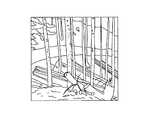
図4は、カメラ画像を例示する図である。 FIG. 4 is a diagram illustrating a camera image.
図4Aは、砕石作業現場におけるカメラ画像の例である。判定部32は、例えば図4Aに示されるカメラ画像から、画像認識処理によりショベルが砕石作業現場にいることを認識し、ショベルによる作業が砕石の積み卸し作業であると判定する。 FIG. 4A is an example of a camera image at a crushed stone work site. From the camera image shown in FIG. 4A, for example, the
図4Bは、スクラップのマテハン作業現場におけるカメラ画像の例である。判定部32は、例えば図4Bに示されるカメラ画像から、画像認識処理によりショベルがスクラップのマテハン作業現場にいることを認識し、ショベルによる作業がスクラップのマテリアルハンドリングであると判定する。ショベルは、スクラップのマテハンを行う場合には、例えばアーム先端部にマグネット(金属吸着用)やグラップル(非鉄金属用)が装着される。 FIG. 4B is an example of a camera image at a material handling work site for scrap. From the camera image shown in FIG. 4B, for example, the
図4Cは、林業における伐採作業現場におけるカメラ画像の例である。判定部32は、例えば図4Cに示されるカメラ画像から、画像認識処理によりショベルが林業における伐採現場にいることを認識し、ショベルによる作業が伐採作業であると判定する。ショベルは、例えば上部旋回体3が旋回して、上部旋回体3と共に旋回するアーム5及びバケット6で木をなぎ倒すように伐採できる。ショベルは、伐採を行う場合には、例えばアーム先端部にハーベスタが装着される。 FIG. 4C is an example of a camera image at a logging work site in the forestry industry. From the camera image shown in FIG. 4C, for example, the
図4Dは、都市土木作業現場におけるカメラ画像の例である。判定部32は、例えば図4Dに示されるカメラ画像から、画像認識処理によりショベルが都市土木作業現場にいることを認識し、ショベルによる作業が掘削等の土木作業であると判定する。 FIG. 4D is an example of a camera image at an urban civil engineering work site. The
判定部32によって判定される作業は、上記にて例示されたものに限られない。判定部32は、例えばカメラ画像からショベルが田圃、堤防、農園等にいることを認識し、それぞれにおける作業を判定してもよい。 The work determined by the
判定部32は、測位装置S8によって取得された現在位置情報と、記憶部33に記憶されている地理情報とに基づいて、ショベルが作業を実行しようとしている作業を判定してもよい。 The
記憶部33には、例えば地図情報、山や川等の地形情報、海岸線、公共施設の境界線、及び行政区画等の位置情報等を含む地理情報が記憶されている。判定部32は、記憶部33からショベルの現在位置における地理情報を取得し、ショベルが山林における伐採現場にいるのか、都市における土木作業現場にいるのか等を地理情報に基づいて判断し、ショベルの作業を判定する。 The
制御部31は、判定部32による判定結果に基づいて、ショベルに設けられている各油圧アクチュエータを制御する。本実施例では、制御部31は、判定部32による判定結果に基づいて、各油圧アクチュエータへの作動油の流量配分を変更する。制御部31は、判定部32による判定結果に基づいて、油圧ポンプとしてのメインポンプ12L,12Rの馬力を変更する。 The
図5は、油圧アクチュエータ制御処理のフローチャートを例示する図である。 FIG. 5 is a diagram illustrating a flowchart of the hydraulic actuator control process.
本実施例では、ショベルにおいてキーオン時に電気系が起動し、図5に示される油圧アクチュエータ制御処理が実行される。油圧アクチュエータ制御処理は、例えば所定時間ごとに実行されてもよく、ショベルの走行停止時に実行されてもよい。 In this embodiment, the electric system is activated at the time of key-on in the excavator, and the hydraulic actuator control process shown in FIG. 5 is executed. The hydraulic actuator control process may be executed, for example, at predetermined time intervals, or may be executed when the excavator is stopped.
油圧アクチュエータ制御処理では、まずステップS101にて、左側方カメラS4、右側方カメラS5、及び後方カメラS6が、それぞれショベルの周囲を撮影する。左側方カメラS4、右側方カメラS5、及び後方カメラS6によって撮影されたカメラ画像は、コントローラ30に送信される。 In the hydraulic actuator control process, first, in step S101, the left side camera S4, the right side camera S5, and the rear camera S6 photograph the surroundings of the excavator, respectively. The camera images taken by the left side camera S4, the right side camera S5, and the rear camera S6 are transmitted to the
次にステップS102にて、判定部32が、左側方カメラS4、右側方カメラS5、及び後方カメラS6によって撮影されたカメラ画像に対して画像認識処理を実行し、各カメラ画像における特徴量を算出する。 Next, in step S102, the
ステップS101にて各カメラがショベルの周囲を撮影し、ステップS102にて判定部32が各カメラ画像の特徴量を算出すると、ステップS103に進む。ステップS103では、判定部32が、算出した特徴量と、記憶部33に記憶されている特徴量データとを照合し、ショベルが作業を行う現場に基づいて作業を判定する。 When each camera photographs the surroundings of the excavator in step S101 and the
必ずしもカメラ画像に基づいて作業を判定しなくてもよく、例えば測位装置S8を用いた現在位置情報に基づいて作業を判定してもよい。測位装置S8によって取得されるショベルの現在位置情報に基づいて作業の判定を行う場合には、ステップS101にて測位装置S8が現在位置情報を取得する。続いてステップS103にて、判定部32が現在位置情報と記憶部33に記憶されている地理情報とに基づいて作業を判定する。カメラ画像及び現在位置情報の両方に基づいて作業を判定してもよい。 It is not always necessary to determine the work based on the camera image, and for example, the work may be determined based on the current position information using the positioning device S8. When the work is determined based on the current position information of the excavator acquired by the positioning device S8, the positioning device S8 acquires the current position information in step S101. Subsequently, in step S103, the
ステップS104では、制御部31が、判定部32による判定結果に基づいて、ショベルに設けられている油圧アクチュエータを制御する。 In step S104, the
図6は、旋回用油圧モータ及びブームシリンダを含む油圧駆動回路55を例示する図である。 FIG. 6 is a diagram illustrating a
図6に示される油圧駆動回路55は、上部旋回体3を旋回駆動させるための旋回用油圧モータ21を駆動させる油圧回路と、ブームシリンダ7を往復駆動させるための油圧回路とを含む。油圧駆動回路55において破線で囲まれた油圧回路部分17は、コントロールバルブに設けられている油圧回路を表している。 The
油圧回路部分17には、パイロット油圧回路からパイロット圧が供給される。より具体的には、ブーム操作レバー16Aで調整されたパイロット圧が、コントロールバルブの流量制御弁153,154に供給される。旋回レバーで調整されたパイロット圧が、コントロールバルブの流量制御弁157に供給される。流量制御弁153,154,157は、パイロット圧に比例してスプールが移動して油路が開くスプール弁である。 Pilot pressure is supplied to the
ブーム操作レバー16Aがブーム4を上昇する方向に操作されると、パイロットポンプから、ブーム操作レバー16Aの操作量に応じて調整されたパイロット圧が流量制御弁153,154に供給される。パイロット圧により流量制御弁153,154のスプールが移動して油路が開き、メインポンプ12L,12Rからの作動油がそれぞれ流量制御弁153,154を介してブームシリンダ7のボトム側に供給され、ブーム4が上昇する。 When the
旋回レバーが上部旋回体3を旋回させる方向に操作されると、パイロットポンプから、旋回レバーの操作量に応じて調整されたパイロット圧が流量制御弁157に供給される。パイロット圧により流量制御弁157のスプールが移動して油路が開き、メインポンプ12L,12Rからの作動油が旋回用油圧モータ21に供給され、上部旋回体3が旋回する。 When the swivel lever is operated in the direction of swiveling the
メインポンプ12Lと流量制御弁157との間には、可変絞り弁60が設けられている。可変絞り弁60は、制御部31から送信される制御信号により、その開度を変更できる弁である。 A
可変絞り弁60が制御信号に応じて開度を小さくすると、メインポンプ12Lから流量制御弁157を介して旋回用油圧モータ21に供給される作動油の流量が低下する。流量制御弁157への作動油の流量が低下することで、流量制御弁153を介してブームシリンダ7に流れる作動油の流量が増加することになる。この状態では、旋回用油圧モータ21は作動油の流量が減ることで出力トルクが低下し、ブームシリンダ7は作動油の流量が増えることでシリンダ出力が上昇する。 When the opening degree of the
可変絞り弁60が制御信号に応じて開度を大きくすると、流量制御弁157を介して旋回用油圧モータ21に流れる作動油の流量が増加する。流量制御弁157への作動油の流量が増加することで、流量制御弁153を介してブームシリンダ7に流れる作動油の流量が低下することになる。この状態では、旋回用油圧モータ21は作動油の流量が増えることで出力トルクが上昇し、ブームシリンダ7は作動油の流量が減ることでシリンダ出力が低下する。 When the
制御部31は、判定部32によるショベルの作業判定結果に基づいて、開度を変更させる制御信号を可変絞り弁60に送信する。例えば、砕石や土木における作業では、上部旋回体3を旋回させるよりも、ブーム4を昇降させることが多くなる。そこで、制御部31は、判定部32によってショベルの作業が砕石や土木と判定された場合には、可変絞り弁60の開度を小さくさせる制御信号を送信する。 The
可変絞り弁60が開度を小さくすると、流量制御弁157への作動油の流量が減って旋回用油圧モータ21の出力トルクが下がり、流量制御弁153への作動油の流量が増えてブームシリンダ7のシリンダ出力が上がる。このように、ショベルの作業が砕石や土木等の場合には、作業における使用頻度が上がるブームシリンダ7への作動油の流量を増やしてシリンダ出力を上げるように、制御部31が作動油の流量を調整する。 When the
例えばマテハンや伐採における作業では、ブーム4を昇降させるよりも、上部旋回体3を旋回させることが多くなる。そこで、制御部31は、判定部32によってショベルの作業がマテハンや伐採と判定された場合には、可変絞り弁60の開度を大きくさせる制御信号を送信する。 For example, in material handling and logging operations, the
可変絞り弁60が開度を大きくすると、流量制御弁157への作動油の流量が増えて旋回用油圧モータ21の出力トルクが上がり、流量制御弁153への作動油の流量が減ってブームシリンダ7のシリンダ出力が下がる。このように、ショベルの作業がマテハンや伐採等の場合には、作業における使用頻度が上がる旋回用油圧モータ21への作動油の流量を増やして出力トルクを上げるように、制御部31が作動油の流量を調整する。 When the
上記したように、ショベルによる作業に応じて可変絞り弁60の開度を変更して油圧アクチュエータとしての旋回用油圧モータ21及びブームシリンダ7への作動油の流量配分を変更することで、作業に必要な出力を無駄なく得ることが可能になる。 As described above, by changing the opening degree of the
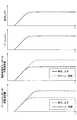
図7は、レバー操作量及び油圧アクチュエータへの作動油流量のタイムチャートを例示する図である。図7に示されている各グラフは、上段から順に、旋回レバーの操作により調整されたパイロット圧、ブーム操作レバーの操作により調整されたパイロット圧、旋回用油圧モータ21への作動油の流量、ブームシリンダ7への作動油の流量を示している。 FIG. 7 is a diagram illustrating a time chart of the lever operation amount and the hydraulic oil flow rate to the hydraulic actuator. In each graph shown in FIG. 7, in order from the top, the pilot pressure adjusted by the operation of the swivel lever, the pilot pressure adjusted by the operation of the boom operating lever, the flow rate of the hydraulic oil to the swivel
本実施例では、ショベルの作業が砕石及び土木の場合には、旋回用油圧モータ21への流量を下げてブームシリンダ7への流量を上げるように可変絞り弁60が制御される。ショベルの作業がマテハン及び伐採の場合には、旋回用油圧モータ21への流量を上げてブームシリンダ7への流量を下げるように可変絞り弁60が制御される。 In this embodiment, when the excavator work is crushed stone or civil engineering, the
このため、旋回用油圧モータ21への作動油流量の最大値は、ショベルの作業がマテハン及び伐採の場合の方が、砕石及び土木の場合よりも大きくなる。逆に、ブームシリンダ7への作動油流量の最大値は、ショベルの作業が砕石及び土木の場合の方が、マテハン及び伐採の場合よりも大きくなる。 Therefore, the maximum value of the hydraulic oil flow rate to the turning
このように、判定部32による判定結果に基づいて制御部31が旋回用油圧モータ21及びブームシリンダ7への作動油の流量を変更することで、ショベルの作業に応じて作動油の流量配分を最適化し、各作業において必要な出力を無駄なく得ることが可能になる。 In this way, the
本実施例では、旋回用油圧モータ21への作動油の流量を調整するように油圧駆動回路が構成されているが、他の油圧アクチュエータへの作動油の流量を調整するように油圧駆動回路が構成されてもよい。例えば、ブームシリンダ7、アームシリンダ8、及びバケットシリンダ9への作動油の流量を調整するように、油圧駆動回路の各部に可変絞り弁を設け、制御部31が各可変絞り弁の開度を制御してもよい。 In this embodiment, the hydraulic drive circuit is configured to adjust the flow rate of hydraulic oil to the swivel
制御部31は、判定部32による判定結果に基づいて、メインポンプ12L,12Rの出力馬力を変更してもよい。 The
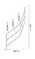
図8は、メインポンプ12L,12Rにおけるポンプ圧力とポンプ流量との関係を例示する図である。本実施例では、スピード・パワー重視の第1作業モード、燃費優先の第2作業モード、微操作に適した第3作業モードがショベルに設けられている。各作業モードは、メインポンプ12L,12Rにおけるポンプ圧力に対するポンプ流量が調整され、出力馬力が第1作業モード>第2作業モード>第3作業モードとなるように設定されている。 FIG. 8 is a diagram illustrating the relationship between the pump pressure and the pump flow rate in the
制御部31は、判定部32によって判定されたショベルの作業に応じて予め定められている作業モードを設定し、メインポンプ12L,12Rの出力馬力を変更する。制御部31は、例えば、ショベルの作業が砕石や土木の場合には第1作業モードに設定し、マテハンや伐採の場合には第2作業モードに設定し、その他の作業の場合には第3作業モードに設定する。このように、制御部31は、作業内容に応じて高い出力馬力が必要な場合には第1作業モードに設定し、低い出力馬力でも作業できる場合には第3作業モードに設定する等、ショベルの作業に応じて予め定められている作業モードを設定する。 The
制御部31は、例えば、作業モードに対応する制御信号をレギュレータ13L,13Rに送信し、斜板傾転角を調整して吐出量を増減させることでメインポンプ12L,12Rの出力馬力を制御する。制御部31は、図3に示すように、作業モードに対応する制御信号をエンジン11に送信し、エンジン回転数を調整することでメインポンプ12L,12Rの出力馬力を制御してもよい。 The
このように、ショベルによる作業に応じて作業モードを設定し、メインポンプ12L,12Rの出力馬力を制御することで、作業において必要以上の馬力を出力することなく、油圧アクチュエータの制御を最適化することが可能になる。 In this way, by setting the work mode according to the work by the excavator and controlling the output horsepower of the
以上、本発明の好ましい実施例について詳説したが、本発明は上記した実施例に制限されることはなく、本発明の範囲を逸脱することなしに上述した実施例に種々の変形及び置換を加えることができる。 Although the preferred examples of the present invention have been described in detail above, the present invention is not limited to the above-mentioned examples, and various modifications and substitutions are added to the above-mentioned examples without departing from the scope of the present invention. be able to.
また、本願は、2015年12月28日に出願した日本国特許出願2015−256682号に基づく優先権を主張するものであり、この日本国特許出願の全内容を本願に参照により援用する。 In addition, this application claims priority based on Japanese Patent Application No. 2015-256682 filed on December 28, 2015, and the entire contents of this Japanese patent application are incorporated herein by reference.
1 下部走行体
3 上部旋回体
4 ブーム
5 アーム
6 バケット
7 ブームシリンダ
8 アームシリンダ
9 バケットシリンダ
11 エンジン
12L,12R メインポンプ
13L,13R レギュレータ
30 コントローラ
31 制御部
32 判定部
33 記憶部
S4 左側方カメラ
S5 右側方カメラ
S6 後方カメラ
S8 測位装置1 Lower traveling
Claims (7)
Translated fromJapanese前記下部走行体に旋回自在に搭載される上部旋回体と、
エンジンによって駆動される油圧ポンプが吐出する作動油によって作動する複数の油圧アクチュエータと、
作業現場の種別を認識して作業を判定する判定部と、前記判定部による判定結果に基づいて、前記エンジン、前記油圧ポンプ、及び、前記複数の油圧アクチュエータのうち少なくとも何れか一つを制御する制御部と、を有することを特徴とするショベル。The lower traveling body that performs the running operation and
An upper swivel body that is freely mounted on the lower traveling body and
Multiple hydraulic actuators operated by hydraulic oil discharged by a hydraulic pump driven by an engine,
A determination unit that recognizes the type of work site and determines work, and controls at least one of the engine, the hydraulic pump, and the plurality of hydraulic actuators based on the determination result by the determination unit. An excavator characterized by having a control unit.
前記判定部は、前記撮像装置によって撮影された画像に基づいて、前記作業を判定することを特徴とする請求項1に記載のショベル。It has an imaging device that captures surrounding images,
The excavator according to claim 1, wherein the determination unit determines the work based on an image taken by the image pickup apparatus.
地理情報を記憶する記憶部と、を有し、
前記判定部は、前記測位装置による測定結果及び前記地理情報に基づいて、前記作業を判定することを特徴とする請求項1に記載のショベル。A positioning device that acquires the current position and
It has a storage unit that stores geographic information,
The excavator according to claim 1, wherein the determination unit determines the work based on the measurement result by the positioning device and the geographic information.
Applications Claiming Priority (3)
| Application Number | Priority Date | Filing Date | Title |
|---|---|---|---|
| JP2015256682 | 2015-12-28 | ||
| JP2015256682 | 2015-12-28 | ||
| PCT/JP2016/089045WO2017115837A1 (en) | 2015-12-28 | 2016-12-28 | Excavator |
Related Child Applications (1)
| Application Number | Title | Priority Date | Filing Date |
|---|---|---|---|
| JP2019123229ADivisionJP6999604B2 (en) | 2015-12-28 | 2019-07-01 | Excavator and image processing system at work site |
Publications (2)
| Publication Number | Publication Date |
|---|---|
| JPWO2017115837A1 JPWO2017115837A1 (en) | 2018-10-25 |
| JP6932648B2true JP6932648B2 (en) | 2021-09-08 |
Family
ID=59225264
Family Applications (3)
| Application Number | Title | Priority Date | Filing Date |
|---|---|---|---|
| JP2017559233AActiveJP6932648B2 (en) | 2015-12-28 | 2016-12-28 | Excavator |
| JP2019123229AActiveJP6999604B2 (en) | 2015-12-28 | 2019-07-01 | Excavator and image processing system at work site |
| JP2021172042APendingJP2022009325A (en) | 2015-12-28 | 2021-10-20 | Discrimination system at work site, and image processing system of work site |
Family Applications After (2)
| Application Number | Title | Priority Date | Filing Date |
|---|---|---|---|
| JP2019123229AActiveJP6999604B2 (en) | 2015-12-28 | 2019-07-01 | Excavator and image processing system at work site |
| JP2021172042APendingJP2022009325A (en) | 2015-12-28 | 2021-10-20 | Discrimination system at work site, and image processing system of work site |
Country Status (6)
| Country | Link |
|---|---|
| US (1) | US10907322B2 (en) |
| EP (1) | EP3399110B1 (en) |
| JP (3) | JP6932648B2 (en) |
| KR (1) | KR102570491B1 (en) |
| CN (1) | CN108431337A (en) |
| WO (1) | WO2017115837A1 (en) |
Families Citing this family (7)
| Publication number | Priority date | Publication date | Assignee | Title |
|---|---|---|---|---|
| JP6903564B2 (en)* | 2017-12-22 | 2021-07-14 | ヤンマーパワーテクノロジー株式会社 | Work vehicle |
| KR20200105651A (en)* | 2018-01-10 | 2020-09-08 | 스미토모 겐키 가부시키가이샤 | Shovel and shovel management system |
| JP7166088B2 (en)* | 2018-06-28 | 2022-11-07 | 株式会社小松製作所 | System, method, and method of manufacturing trained model for determining work by work vehicle |
| EP3868963A4 (en) | 2018-10-19 | 2021-12-22 | Sumitomo Construction Machinery Co., Ltd. | EXCAVATOR |
| CN109469149A (en)* | 2018-11-07 | 2019-03-15 | 马鞍山沐及信息科技有限公司 | A kind of control method of excavator |
| JPWO2023190031A1 (en)* | 2022-03-31 | 2023-10-05 | ||
| JPWO2025100538A1 (en)* | 2023-11-08 | 2025-05-15 |
Family Cites Families (43)
| Publication number | Priority date | Publication date | Assignee | Title |
|---|---|---|---|---|
| JPS5145159B1 (en) | 1964-08-21 | 1976-12-02 | ||
| CA2201626A1 (en)* | 1995-10-09 | 1997-04-09 | Shin Caterpillar Mitsubishi Ltd. | Control apparatus for construction machine |
| JPH09270945A (en)* | 1996-03-29 | 1997-10-14 | Hitachi Constr Mach Co Ltd | Camera visual field angle controller for remote control machine |
| JPH1072851A (en)* | 1996-08-30 | 1998-03-17 | Shin Caterpillar Mitsubishi Ltd | Invading moving body detection device |
| US5944764A (en)* | 1997-06-23 | 1999-08-31 | Caterpillar Inc. | Method for monitoring the work cycle of earth moving machinery during material removal |
| US6061617A (en)* | 1997-10-21 | 2000-05-09 | Case Corporation | Adaptable controller for work vehicle attachments |
| EP0964221A4 (en)* | 1997-12-25 | 2000-08-23 | Yamanashi Hitachi Construction | Land mine exploding apparatus and method |
| US6336067B1 (en)* | 1998-08-12 | 2002-01-01 | Hitachi Construction Machinery Co., Ltd. | Electronic control system and control device for construction machine |
| US6363632B1 (en) | 1998-10-09 | 2002-04-02 | Carnegie Mellon University | System for autonomous excavation and truck loading |
| WO2000037744A1 (en) | 1998-12-22 | 2000-06-29 | Caterpillar Inc. | Tool recognition and control system for a work machine |
| JP2000291076A (en)* | 1999-04-01 | 2000-10-17 | Tokai Rika Co Ltd | Power shovel |
| US6735888B2 (en)* | 2001-05-18 | 2004-05-18 | Witten Technologies Inc. | Virtual camera on the bucket of an excavator displaying 3D images of buried pipes |
| JP2004324511A (en) | 2003-04-24 | 2004-11-18 | Sumitomo (Shi) Construction Machinery Manufacturing Co Ltd | Control device of construction machine |
| US7539570B2 (en)* | 2004-06-22 | 2009-05-26 | Caterpillar S.A.R.L. | Machine operating system and method |
| US7630793B2 (en)* | 2004-12-10 | 2009-12-08 | Caterpillar S.A.R.L. | Method of altering operation of work machine based on work tool performance footprint to maintain desired relationship between operational characteristics of work tool and work machine |
| JP4746384B2 (en)* | 2005-09-01 | 2011-08-10 | 株式会社クボタ | Automatic control system for work equipment |
| JP4575334B2 (en) | 2006-06-28 | 2010-11-04 | 日立建機株式会社 | Construction machinery |
| JP4746000B2 (en) | 2007-03-27 | 2011-08-10 | 株式会社小松製作所 | Fuel saving driving support method and fuel saving driving support system for construction machinery |
| US8244438B2 (en)* | 2008-01-31 | 2012-08-14 | Caterpillar Inc. | Tool control system |
| US8285458B2 (en)* | 2008-04-18 | 2012-10-09 | Caterpillar Inc. | Machine with automatic operating mode determination |
| JP2009281149A (en)* | 2008-05-19 | 2009-12-03 | Kobelco Contstruction Machinery Ltd | Engine control device and working machine equipped with the same |
| WO2009148364A1 (en)* | 2008-06-03 | 2009-12-10 | Volvo Construction Equipment Ab | A method for controlling a power source |
| JP5145159B2 (en) | 2008-08-04 | 2013-02-13 | 東急建設株式会社 | Work machine |
| WO2012053105A1 (en)* | 2010-10-22 | 2012-04-26 | 日立建機株式会社 | Work machine peripheral monitoring device |
| JP5555190B2 (en) | 2011-02-22 | 2014-07-23 | 株式会社小松製作所 | Hydraulic excavator display system and control method thereof |
| JP5059954B2 (en)* | 2011-02-22 | 2012-10-31 | 株式会社小松製作所 | Excavator display system and control method thereof. |
| JP5836362B2 (en)* | 2011-03-08 | 2015-12-24 | 住友建機株式会社 | Excavator and control method of excavator |
| US8800177B2 (en)* | 2011-04-26 | 2014-08-12 | Steve Harrington | Pneumatic excavation system and method of use |
| JP5802476B2 (en)* | 2011-08-09 | 2015-10-28 | 株式会社トプコン | Construction machine control system |
| JP5755578B2 (en) | 2012-02-02 | 2015-07-29 | 住友重機械工業株式会社 | Ambient monitoring device |
| EP2902550A4 (en)* | 2012-09-20 | 2016-07-20 | Volvo Constr Equip Ab | Method for automatically recognizing and setting attachment and device therefor |
| JP6080585B2 (en)* | 2013-02-08 | 2017-02-15 | 日立建機株式会社 | How to create a work content database |
| CN103114617B (en)* | 2013-03-21 | 2015-03-25 | 河北大学 | Vertical milling type land leveler |
| US9376784B2 (en)* | 2013-03-29 | 2016-06-28 | Caterpillar Inc. | Control system for dual boom machine |
| KR102079399B1 (en)* | 2013-05-22 | 2020-02-19 | 두산인프라코어 주식회사 | Method and Apparatus for Controlling Output of Construction Equipment Using Vision System |
| US20150097412A1 (en)* | 2013-10-09 | 2015-04-09 | Caterpillar Inc. | Determing an activity of a mobile machine |
| JP6124302B2 (en)* | 2013-11-05 | 2017-05-10 | キャタピラー エス エー アール エル | Work machine |
| CN203594072U (en)* | 2013-11-15 | 2014-05-14 | 中外合资沃得重工(中国)有限公司 | Excavator safety control system |
| EP3112539B1 (en)* | 2014-02-24 | 2017-11-22 | Sumitomo (S.H.I.) Construction Machinery Co., Ltd. | Shovel and shovel control method |
| WO2015162710A1 (en) | 2014-04-23 | 2015-10-29 | 株式会社日立製作所 | Excavation device |
| WO2015186588A1 (en)* | 2014-06-03 | 2015-12-10 | 住友重機械工業株式会社 | Human detection system for construction machine |
| EP3418455B1 (en)* | 2014-06-20 | 2020-04-08 | Sumitomo Heavy Industries, Ltd. | Shovel and control method thereof |
| CN107251093A (en)* | 2015-03-30 | 2017-10-13 | 沃尔沃建筑设备公司 | The system and method that the material of scraper bowl for determining material mechanically moving loads situation |
- 2016
- 2016-12-28JPJP2017559233Apatent/JP6932648B2/enactiveActive
- 2016-12-28EPEP16881811.0Apatent/EP3399110B1/enactiveActive
- 2016-12-28KRKR1020187019313Apatent/KR102570491B1/enactiveActive
- 2016-12-28WOPCT/JP2016/089045patent/WO2017115837A1/ennot_activeCeased
- 2016-12-28CNCN201680076768.4Apatent/CN108431337A/enactivePending
- 2018
- 2018-06-26USUS16/018,366patent/US10907322B2/enactiveActive
- 2019
- 2019-07-01JPJP2019123229Apatent/JP6999604B2/enactiveActive
- 2021
- 2021-10-20JPJP2021172042Apatent/JP2022009325A/enactivePending
Also Published As
| Publication number | Publication date |
|---|---|
| JP2022009325A (en) | 2022-01-14 |
| JPWO2017115837A1 (en) | 2018-10-25 |
| EP3399110A4 (en) | 2019-01-02 |
| JP2019167821A (en) | 2019-10-03 |
| EP3399110B1 (en) | 2021-02-17 |
| US10907322B2 (en) | 2021-02-02 |
| EP3399110A1 (en) | 2018-11-07 |
| JP6999604B2 (en) | 2022-01-18 |
| KR102570491B1 (en) | 2023-08-23 |
| KR20180097612A (en) | 2018-08-31 |
| CN108431337A (en) | 2018-08-21 |
| WO2017115837A1 (en) | 2017-07-06 |
| US20180298586A1 (en) | 2018-10-18 |
Similar Documents
| Publication | Publication Date | Title |
|---|---|---|
| JP6999604B2 (en) | Excavator and image processing system at work site | |
| JP7402736B2 (en) | Excavator and its control method | |
| JP6915000B2 (en) | Excavator | |
| US11926994B2 (en) | Excavator, display device for excavator, and terminal apparatus | |
| JP7658661B2 (en) | Excavator and excavator management system | |
| JP7605944B2 (en) | Excavator | |
| US20230078047A1 (en) | Excavator and system for excavator | |
| CN114829710B (en) | Shovel, remote operation support device | |
| US20240271392A1 (en) | Excavator | |
| WO2022085556A1 (en) | Work machine | |
| JP2021025198A (en) | Shovel | |
| US20240011247A1 (en) | Excavator and support system of excavator | |
| US20250188704A1 (en) | Excavator and control device for excavator | |
| US20250207369A1 (en) | Control system for excavator and excavator | |
| US20250270787A1 (en) | Excavator | |
| US20250207360A1 (en) | Working machine, and remote-control system for working machine | |
| JP2018145623A (en) | Shovel |
Legal Events
| Date | Code | Title | Description |
|---|---|---|---|
| A625 | Written request for application examination (by other person) | Free format text:JAPANESE INTERMEDIATE CODE: A625 Effective date:20180918 | |
| A131 | Notification of reasons for refusal | Free format text:JAPANESE INTERMEDIATE CODE: A131 Effective date:20190709 | |
| A521 | Request for written amendment filed | Free format text:JAPANESE INTERMEDIATE CODE: A523 Effective date:20190909 | |
| A02 | Decision of refusal | Free format text:JAPANESE INTERMEDIATE CODE: A02 Effective date:20200303 | |
| A521 | Request for written amendment filed | Free format text:JAPANESE INTERMEDIATE CODE: A523 Effective date:20200603 | |
| C60 | Trial request (containing other claim documents, opposition documents) | Free format text:JAPANESE INTERMEDIATE CODE: C60 Effective date:20200603 | |
| A911 | Transfer to examiner for re-examination before appeal (zenchi) | Free format text:JAPANESE INTERMEDIATE CODE: A911 Effective date:20200610 | |
| C21 | Notice of transfer of a case for reconsideration by examiners before appeal proceedings | Free format text:JAPANESE INTERMEDIATE CODE: C21 Effective date:20200616 | |
| A912 | Re-examination (zenchi) completed and case transferred to appeal board | Free format text:JAPANESE INTERMEDIATE CODE: A912 Effective date:20201002 | |
| C211 | Notice of termination of reconsideration by examiners before appeal proceedings | Free format text:JAPANESE INTERMEDIATE CODE: C211 Effective date:20201006 | |
| C22 | Notice of designation (change) of administrative judge | Free format text:JAPANESE INTERMEDIATE CODE: C22 Effective date:20201208 | |
| C22 | Notice of designation (change) of administrative judge | Free format text:JAPANESE INTERMEDIATE CODE: C22 Effective date:20210126 | |
| C13 | Notice of reasons for refusal | Free format text:JAPANESE INTERMEDIATE CODE: C13 Effective date:20210302 | |
| A521 | Request for written amendment filed | Free format text:JAPANESE INTERMEDIATE CODE: A523 Effective date:20210506 | |
| C23 | Notice of termination of proceedings | Free format text:JAPANESE INTERMEDIATE CODE: C23 Effective date:20210706 | |
| C03 | Trial/appeal decision taken | Free format text:JAPANESE INTERMEDIATE CODE: C03 Effective date:20210817 | |
| C30A | Notification sent | Free format text:JAPANESE INTERMEDIATE CODE: C3012 Effective date:20210817 | |
| A61 | First payment of annual fees (during grant procedure) | Free format text:JAPANESE INTERMEDIATE CODE: A61 Effective date:20210818 | |
| R150 | Certificate of patent or registration of utility model | Ref document number:6932648 Country of ref document:JP Free format text:JAPANESE INTERMEDIATE CODE: R150 |