JP6932607B2 - DC power supply system - Google Patents
DC power supply systemDownload PDFInfo
- Publication number
- JP6932607B2 JP6932607B2JP2017197674AJP2017197674AJP6932607B2JP 6932607 B2JP6932607 B2JP 6932607B2JP 2017197674 AJP2017197674 AJP 2017197674AJP 2017197674 AJP2017197674 AJP 2017197674AJP 6932607 B2JP6932607 B2JP 6932607B2
- Authority
- JP
- Japan
- Prior art keywords
- voltage
- bus
- power
- storage battery
- supply system
- Prior art date
- Legal status (The legal status is an assumption and is not a legal conclusion. Google has not performed a legal analysis and makes no representation as to the accuracy of the status listed.)
- Active
Links
Images


Classifications
- H—ELECTRICITY
- H02—GENERATION; CONVERSION OR DISTRIBUTION OF ELECTRIC POWER
- H02J—CIRCUIT ARRANGEMENTS OR SYSTEMS FOR SUPPLYING OR DISTRIBUTING ELECTRIC POWER; SYSTEMS FOR STORING ELECTRIC ENERGY
- H02J1/00—Circuit arrangements for DC mains or DC distribution networks
- H02J1/10—Parallel operation of DC sources
- H—ELECTRICITY
- H02—GENERATION; CONVERSION OR DISTRIBUTION OF ELECTRIC POWER
- H02J—CIRCUIT ARRANGEMENTS OR SYSTEMS FOR SUPPLYING OR DISTRIBUTING ELECTRIC POWER; SYSTEMS FOR STORING ELECTRIC ENERGY
- H02J3/00—Circuit arrangements for AC mains or AC distribution networks
- H02J3/28—Arrangements for balancing of the load in a network by storage of energy
- H02J3/32—Arrangements for balancing of the load in a network by storage of energy using batteries with converting means
- H—ELECTRICITY
- H02—GENERATION; CONVERSION OR DISTRIBUTION OF ELECTRIC POWER
- H02J—CIRCUIT ARRANGEMENTS OR SYSTEMS FOR SUPPLYING OR DISTRIBUTING ELECTRIC POWER; SYSTEMS FOR STORING ELECTRIC ENERGY
- H02J7/00—Circuit arrangements for charging or depolarising batteries or for supplying loads from batteries
- H02J7/34—Parallel operation in networks using both storage and other DC sources, e.g. providing buffering
- H02J7/35—Parallel operation in networks using both storage and other DC sources, e.g. providing buffering with light sensitive cells
- H—ELECTRICITY
- H02—GENERATION; CONVERSION OR DISTRIBUTION OF ELECTRIC POWER
- H02J—CIRCUIT ARRANGEMENTS OR SYSTEMS FOR SUPPLYING OR DISTRIBUTING ELECTRIC POWER; SYSTEMS FOR STORING ELECTRIC ENERGY
- H02J3/00—Circuit arrangements for AC mains or AC distribution networks
- H02J3/38—Arrangements for parallely feeding a single network by two or more generators, converters or transformers
- Y—GENERAL TAGGING OF NEW TECHNOLOGICAL DEVELOPMENTS; GENERAL TAGGING OF CROSS-SECTIONAL TECHNOLOGIES SPANNING OVER SEVERAL SECTIONS OF THE IPC; TECHNICAL SUBJECTS COVERED BY FORMER USPC CROSS-REFERENCE ART COLLECTIONS [XRACs] AND DIGESTS
- Y02—TECHNOLOGIES OR APPLICATIONS FOR MITIGATION OR ADAPTATION AGAINST CLIMATE CHANGE
- Y02E—REDUCTION OF GREENHOUSE GAS [GHG] EMISSIONS, RELATED TO ENERGY GENERATION, TRANSMISSION OR DISTRIBUTION
- Y02E10/00—Energy generation through renewable energy sources
- Y02E10/50—Photovoltaic [PV] energy
- Y02E10/56—Power conversion systems, e.g. maximum power point trackers
- Y—GENERAL TAGGING OF NEW TECHNOLOGICAL DEVELOPMENTS; GENERAL TAGGING OF CROSS-SECTIONAL TECHNOLOGIES SPANNING OVER SEVERAL SECTIONS OF THE IPC; TECHNICAL SUBJECTS COVERED BY FORMER USPC CROSS-REFERENCE ART COLLECTIONS [XRACs] AND DIGESTS
- Y02—TECHNOLOGIES OR APPLICATIONS FOR MITIGATION OR ADAPTATION AGAINST CLIMATE CHANGE
- Y02E—REDUCTION OF GREENHOUSE GAS [GHG] EMISSIONS, RELATED TO ENERGY GENERATION, TRANSMISSION OR DISTRIBUTION
- Y02E10/00—Energy generation through renewable energy sources
- Y02E10/70—Wind energy
- Y02E10/76—Power conversion electric or electronic aspects
- Y—GENERAL TAGGING OF NEW TECHNOLOGICAL DEVELOPMENTS; GENERAL TAGGING OF CROSS-SECTIONAL TECHNOLOGIES SPANNING OVER SEVERAL SECTIONS OF THE IPC; TECHNICAL SUBJECTS COVERED BY FORMER USPC CROSS-REFERENCE ART COLLECTIONS [XRACs] AND DIGESTS
- Y02—TECHNOLOGIES OR APPLICATIONS FOR MITIGATION OR ADAPTATION AGAINST CLIMATE CHANGE
- Y02E—REDUCTION OF GREENHOUSE GAS [GHG] EMISSIONS, RELATED TO ENERGY GENERATION, TRANSMISSION OR DISTRIBUTION
- Y02E70/00—Other energy conversion or management systems reducing GHG emissions
- Y02E70/30—Systems combining energy storage with energy generation of non-fossil origin
Landscapes
- Engineering & Computer Science (AREA)
- Power Engineering (AREA)
- Charge And Discharge Circuits For Batteries Or The Like (AREA)
- Supply And Distribution Of Alternating Current (AREA)
- Direct Current Feeding And Distribution (AREA)
- Secondary Cells (AREA)
Description
Translated fromJapanese本発明は、直流電力を供給する直流給電システムに関する。 The present invention relates to a DC power supply system that supplies DC power.
特許文献1は、複数の分散電源ユニットが直流バスを介して接続された分散電源システムを開示する。この分散電源システムは、直流バスの電圧変動を所定範囲内で許容し、この直流バスの電圧値に基づいて各分散電源ユニットを自律的に協調運転する。この分散電源システムは、風力発電ユニットと、太陽光発電ユニットと、電力貯蔵ユニットと、系統連係ユニットとを含む。なお、系統連係ユニットは分散電源システムの直流バスと外部の交流の電力系統との間で電力を相互に供給し合う。 Patent Document 1 discloses a distributed power supply system in which a plurality of distributed power supply units are connected via a DC bus. This distributed power supply system allows voltage fluctuations of the DC bus within a predetermined range, and autonomously cooperates with each distributed power supply unit based on the voltage value of the DC bus. This distributed generation system includes a wind power generation unit, a photovoltaic power generation unit, a power storage unit, and a grid linkage unit. The grid linkage unit mutually supplies power between the DC bus of the distributed power supply system and the external AC power system.
特許文献1に記載されている電力貯蔵ユニットは、二次電池(蓄電池)を含む。蓄電池は、充電する際に過充電を防止する必要がある。このため、一般に、蓄電池は、印加される電圧が過充電保護電圧を超えると充電を停止する過充電保護回路を有する。 The power storage unit described in Patent Document 1 includes a secondary battery (storage battery). The storage battery needs to prevent overcharging when it is charged. Therefore, in general, the storage battery has an overcharge protection circuit that stops charging when the applied voltage exceeds the overcharge protection voltage.
本発明の目的は、蓄電池における過充電保護回路を不要とすることができる直流給電システムを提供することである。 An object of the present invention is to provide a DC power supply system that can eliminate the need for an overcharge protection circuit in a storage battery.
上記目的を達成するために、本発明の直流給電システムは、
直流バスと、
前記直流バスに接続されかつ充電可能な最大の電圧である所定の充電終止電圧が過充電保護電圧以下である蓄電池を有する蓄電装置と、
前記直流バスに接続されかつ前記直流バスの電圧が前記蓄電池の充電終止電圧よりも低いときにのみ、直流電圧を前記直流バスに出力する1つ以上の発電装置である直流電力源と、
を備えることを特徴とする。In order to achieve the above object, the DC power supply system of the present invention
DC bus and
A power storage device having a storage battery whose predetermined charge termination voltage, which is the maximum voltageconnected to the DC bus and can be charged, is equal to or lower than the overcharge protection voltage.
A DC power sourcethat isone or more power generators that output a DC voltage to the DC bus only when it is connected to the DC bus and the voltage of the DC bus is lower than the charge termination voltage of the storage battery.
It is characterized by having.
好ましくは、本発明の直流給電システムは、
直流バスと、
前記直流バスに接続されかつ充電可能な最大の電圧である所定の充電終止電圧が過充電保護電圧以下である蓄電池を有する蓄電装置と、
前記直流バスに接続されかつ直流電圧を前記直流バスに出力する1つ以上の発電装置である直流電力源と、
前記直流バスに接続されかつ前記直流バスの電圧が前記蓄電池の充電終止電圧以上であるときに、前記直流バスの電力を消費する電力消費装置と、
を備えることを特徴とする直流給電システム。Preferably, the DC power supply system of the present invention
DC bus and
A power storage device having a storage battery whose predetermined charge termination voltage, which is the maximum voltageconnected to the DC bus and can be charged, is equal to or lower than the overcharge protection voltage.
A DC power sourcethat is one or more power generators that areconnected to the DC bus and output a DC voltage to the DC bus.
A power consuming device that consumes the power of the DC bus when it is connected to the DC bus and the voltage of the DC bus is equal to or higher than the charge termination voltage of the storage battery.
A DC power supply system characterized by being equipped with.
好ましくは、本発明の直流給電システムは、
前記直流バスの電圧が所定の出力上限電圧より低いときに、交流の電力系統から供給される交流電圧を直流電圧に変換して前記直流バスに出力する系統連係装置を備え、
前記蓄電装置に含まれる蓄電池における放電可能な最小の電圧である所定の放電終止電圧が、前記系統連係装置の出力上限電圧以上かつ前記蓄電池の過放電保護電圧以上であり、
前記蓄電装置が、前記直流バスの電圧が前記放電終止電圧以上であるときに前記蓄電池を前記直流バスに接続するか、または前記蓄電地の正極端子と負極端子の間の電圧が前記放電終止電圧以上であるときに前記蓄電池を前記直流バスに接続し、前記直流バスの電圧が前記放電終止電圧よりも低いときに前記蓄電池を前記直流バスから切り離すか、または前記蓄電地の正極端子と負極端子の間の電圧が前記放電終止電圧よりも低いときに前記蓄電池を前記直流バスから切り離す接続部を有する、
ことを特徴とするPreferably, the DC power supply system of the present invention
A system linkage device is provided which converts an AC voltage supplied from an AC power system into a DC voltage and outputs the AC voltage to the DC bus when the voltage of the DC bus is lower than a predetermined output upper limit voltage.
A predetermined discharge end voltage, which is the minimum voltage that can be discharged in the storage battery included in the power storage device, is equal to or higher than the output upper limit voltage of the grid linkage device and equal to or higher than the over-discharge protection voltage of the storage battery.
The power storage device connects the storage battery to the DC bus when the voltage of the DC bus is equal to or higher than the discharge end voltage, or the voltage between the positive terminal and the negative terminal of the power storage area is the discharge end voltage. When the above is the case, the storage battery is connected to the DC bus, and when the voltage of the DC bus is lower than the discharge end voltage, the storage battery is disconnected from the DC bus, or the positive and negative terminals of the storage area are used. It has a connection that disconnects the storage battery from the DC bus when the voltage between them is lower than the end-of-discharge voltage.
Characterized by
好ましくは、本発明の直流給電システムは、
前記直流電力源が出力することができる最大の直流電流が、前記蓄電池を充電可能な最大の電流である最大充電電流よりも小さいことを特徴とする。Preferably, the DC power supply system of the present invention
The maximum DC current that can be output by the DC power source is smaller than the maximum charging current that is the maximum current that can charge the storage battery.
好ましくは、本発明の直流給電システムは、
前記直流電力源を2つ以上有しており、当該2つ以上の直流電力源が同時に出力することができる直流電流の総和の最大値が、前記最大充電電流の電流値よりも小さいことを特徴とする。Preferably, the DC power supply system of the present invention
It has two or more DC power sources, and the maximum value of the total DC current that can be output by the two or more DC power sources at the same time is smaller than the current value of the maximum charging current. And.
本発明によれば、蓄電池における過充電保護回路を不要とすることができる。 According to the present invention, the overcharge protection circuit in the storage battery can be eliminated.
以下、本発明の実施形態に係る直流給電システムについて図面を参照しながら詳細に説明する。なお、実施形態を説明する全図において、共通の構成要素には同一の符号を付し、繰り返しの説明を省略する。 Hereinafter, the DC power supply system according to the embodiment of the present invention will be described in detail with reference to the drawings. In all the drawings for explaining the embodiments, the common components are designated by the same reference numerals, and the repeated description will be omitted.
図1は、本発明の第1の実施形態に係る直流給電システム1の構成の一例を示す。
直流給電システム1は、風力発電装置10と、太陽光発電装置20と、蓄電装置30と、系統連係装置40と、複数の負荷90と、直流バス100とを有する。
これらの各装置10,20,30,40と負荷90は、直流バス100に接続される。系統連係装置40は、更に電力系統200に接続される。
風力発電装置10と太陽光発電装置20は本発明の直流電力源の例である。風力発電装置10は、所定の上限電圧以下の直流電圧を直流バス100に出力する。太陽光発電装置20も、同様に所定の上限電圧以下の直流電圧を直流バス100に出力する。
系統連係装置40は、直流バス100の電圧が所定の出力上限電圧より低いときに、交流の電力系統200から供給される交流電圧を直流電圧に変換して直流バス100に出力する。なお、系統連係装置40は、本発明の直流電力源に含まれない。FIG. 1 shows an example of the configuration of the DC power supply system 1 according to the first embodiment of the present invention.
The DC power supply system 1 includes a wind
Each of these
The wind
When the voltage of the DC bus 100 is lower than the predetermined output upper limit voltage, the
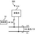
図2に示すように、蓄電装置30は、蓄電池31と、充電電流制限回路32と、制御部33と、スイッチSWとを含む。
風力発電装置10と太陽光発電装置20が出力する最大の電圧は、蓄電装置30の充電終止電圧との関係で定められる。
充電終止電圧は、蓄電池31を充電可能な最大の電圧である。充電終止電圧は、蓄電池31の過充電を防止するための過充電保護電圧以下に定められる。また、放電終止電圧は、蓄電池31が放電可能な最小の電圧である。放電終止電圧は、系統連係装置40の出力上限電圧以上であり、かつ蓄電池31の過放電を防止するための過放電保護電圧以上である所定の電圧に定められる。なお、蓄電池31の過充電保護電圧は(セル毎の過充電保護電圧)×セル数であり、その過放電保護電圧は(セル毎の過放電保護電圧)×セル数である。
充電電流制限回路32は、蓄電池31に入力される電流が充電可能な最大の電流を超えないように蓄電池31の入力電流を制限する。As shown in FIG. 2, the
The maximum voltage output by the wind
The charge termination voltage is the maximum voltage at which the
The charging current limiting
制御部33とスイッチSWとは、本発明の蓄電装置に含まれる接続部の例である。スイッチSWは、例えば、リレーまたは半導体スイッチング素子で実現することができる。制御部33は、直流バス100の電圧が放電終止電圧以上であるときにスイッチSWを閉じて蓄電池31を直流バス100に接続する。または、制御部33は、蓄電池31の正極端子と負極端子の間の電圧が放電終止電圧以上であるときにスイッチSWを閉じて蓄電池31を直流バス100に接続する。また、制御部33は、直流バス100の電圧が放電終止電圧よりも低いときにスイッチSWを開いて蓄電池31を直流バス100から切り離す。または、制御部33は、蓄電池31の正極端子と負極端子の間の電圧が放電終止電圧よりも低いときにスイッチSWを開いて蓄電池31を直流バス100から切り離す。
なお、スイッチSWは、図2(A)に示すように高電位ラインLH側に設けられていてもよいし、図2(B)に示すように低電位ラインLL側に設けられていてもよい。また、高電位ラインLH側と低電位ラインLL側の両方に設けられていてもよい。The
The switch SW may be provided on the high potential line LH side as shown in FIG. 2 (A), or may be provided on the low potential line LL side as shown in FIG. 2 (B). .. Further, it may be provided on both the high potential line LH side and the low potential line LL side.
直流電力源は、直流バス100の電圧が蓄電池31の充電終止電圧よりも低いときにのみ、直流電圧を直流バス100に出力する。
風力発電装置10は、図3に示すように、風力発電機11と、制御部12と、スイッチSWとを含む。制御部12は、直流バス100の電圧が蓄電池31の充電終止電圧よりも低いときにのみ、スイッチSWを閉じて風力発電機11を直流バス100に接続し、直流電流を直流バス100に出力する。なお、風力発電装置10が制御部12とスイッチSWを有する構造は例示に過ぎない。風力発電装置10は、直流バス100の電圧が蓄電池31の充電終止電圧よりも低いときにのみ、直流電流を直流バス100に出力する風力発電装置であれば、他の構造であってもよい。例えば、風力発電装置10は、蓄電池31の充電終止電圧まで電圧を出力することができる風力発電装置であってもよい。
太陽光発電装置20は、図4に示すように、太陽電池21と、制御部22と、スイッチSWとを含む。制御部22は、直流バス100の電圧が蓄電池31の充電終止電圧よりも低いときにのみ、スイッチSWを閉じて太陽電池21を直流バス100に接続し、直流電流を直流バス100に出力する。なお、太陽光発電装置20が制御部22とスイッチSWを有する構造は例示に過ぎない。太陽光発電装置20は、直流バス100の電圧が蓄電池31の充電終止電圧よりも低いときにのみ、直流電流を直流バス100に出力する太陽光発電装置であれば、他の構造であってもよい。例えば、太陽光発電装置20は、蓄電池31の充電終止電圧まで電圧を出力することができる太陽光発電装置であってもよい。The DC power source outputs the DC voltage to the DC bus 100 only when the voltage of the DC bus 100 is lower than the charge termination voltage of the
As shown in FIG. 3, the
As shown in FIG. 4, the photovoltaic
例えば、蓄電池31のセル数が53個、セル毎の過充電保護電圧が2.25V、セル毎の過放電保護電圧が1.9Vのとき、蓄電池31の過充電保護電圧は119.25Vであり、その過放電保護電圧は100.7Vである。従って、蓄電池31の充電終止電圧は119.25V以下に定められ、その放電終止電圧は100.7V以上に定められる。
このとき、風力発電装置10と太陽光発電装置20は、直流バス100の電圧が119.25Vよりも低いときにのみ、直流電圧を直流バス100に出力する。このように、風力発電装置10と太陽光発電装置20は、直流バス100の電圧が蓄電池31の過充電保護電圧よりも低いときにのみ、直流電圧を直流バス100に出力する。従って、第1の実施形態に係る直流給電システム1では、蓄電装置30に過充電保護回路が不要となる。For example, when the number of cells of the
At this time, the wind
なお、仮に、直流バス100の電圧が放電終止電圧(例えば、100.7V)まで低下したときに、電力系統200が直流電圧を出力するならば、蓄電装置30において制御部33とスイッチSWは不要である。しかし、電力系統200は、停電や短絡事故等の異常事態が発生した場合に、その電圧が低下するおそれがある。このような場合に蓄電池31の過放電を防ぐ必要がある。このため、蓄電装置30は制御部33とスイッチSWを備えることが必要である。 If the power system 200 outputs a DC voltage when the voltage of the DC bus 100 drops to the discharge end voltage (for example, 100.7V), the
図5は、本発明の第2の実施形態に係る直流給電システム2の構成の一例を示す。
直流給電システム2は、風力発電装置10Aと、太陽光発電装置20Aと、蓄電装置30と、系統連係装置40と、電力消費装置50と、複数の負荷90と、直流バス100とを有する。
第2の実施形態に係る直流給電システム2は、風力発電装置10Aと太陽光発電装置20Aが第1の実施形態に係る直流給電システム1と異なる。また、第2の実施形態に係る直流給電システム2は、電力消費装置50を有する点が第1の実施形態に係る直流給電システム1と異なる。その他の点では、直流給電システム2と直流給電システム1は同一の構成である。FIG. 5 shows an example of the configuration of the DC
The DC
In the DC
風力発電装置10Aは、通常の一般的な風力発電機である。風力発電装置10Aには出力電圧の上限に特に制限はない。風力発電装置10Aは、この点が第1の実施形態に係る風力発電装置10と異なる。
太陽光発電装置20Aは、太陽電池を含む通常の一般的な太陽光発電装置である。太陽光発電装置20Aには出力電圧の上限に特に制限はない。太陽光発電装置20Aは、この点が第1の実施形態に係る太陽光発電装置20と異なる。
なお、風力発電装置10Aと太陽光発電装置20Aは、本発明の直流電力源の別の例である。The
The photovoltaic
The wind
電力消費装置50は、直流バス100の電圧が蓄電池31を充電可能な最大の電圧である所定の充電終止電圧以上であるときに、直流バス100の電力を消費する。
図6に示すように、電力消費装置50は、抵抗素子51と、制御部52と、スイッチSWとを含む。直流バス100の直流電圧が充電終止電圧以上であるとき、制御部52はスイッチSWを閉じて抵抗素子51を直流バス100に接続する。このとき、抵抗素子51は直流バス100の電力を消費する。このため、直流バス100の電圧は蓄電池31の充電終止電圧を超えることがない。従って、第2の実施形態に係る直流給電システム2でも、第1の実施形態に係る直流給電システム1と同様に、蓄電装置30に過充電保護回路を設ける必要がない。The
As shown in FIG. 6, the
図7は、本発明の第3の実施形態に係る直流給電システム3の構成の一例を示す。
直流給電システム3は、風力発電装置10Bと、太陽光発電装置20Bと、蓄電装置30Aと、系統連係装置40と、複数の負荷90と、直流バス100とを有する。
第3の実施形態に係る直流給電システム3は、風力発電装置10Bと太陽光発電装置20Bと蓄電装置30Aが第1の実施形態に係る直流給電システム1の風力発電装置10と太陽光発電装置20と蓄電装置30と異なる。その他の点では、直流給電システム3と直流給電システム1は同一の構成である。FIG. 7 shows an example of the configuration of the DC
The DC
In the DC
風力発電装置10Bは、所定の最大出力電流以下の直流電流を直流バス100に出力する。同様に、太陽光発電装置20も、所定の最大出力電流以下の直流電流を直流バス100に出力する。なお、風力発電装置10Bと太陽光発電装置20Bの最大出力電流は同一である場合もあるし、異なる場合もある。風力発電装置10Bと太陽光発電装置20Bは本発明の直流電力源の更に別の例である。
また、風力発電装置10Bおよび太陽光発電装置20Bが、直流バス100の電圧が蓄電池31の充電終止電圧よりも低いときにのみ、直流電圧を直流バス100に出力する点は、第1の実施形態に係る風力発電装置10および太陽光発電装置20と同一である。The
Further, the point that the wind
図8に示すように、蓄電装置30Aは、蓄電池31Aと、制御部33と、スイッチSWとを含む。
蓄電池31Aには、充電時に所定の最大充電電流までの電流を流すことができる。風力発電装置10Bの最大出力電流はその最大充電電流よりも小さい。同様に、太陽光発電装置20Bの最大出力電流もその最大充電電流よりも小さい。更に、風力発電装置10Bと太陽光発電装置20Bが同時に出力することができる直流電流の和の最大値(1つ以上の直流電力源が同時に出力することができる直流電流の総和の最大値)は最大充電電流の電流値よりも小さい。As shown in FIG. 8, the
A current up to a predetermined maximum charging current can be passed through the
蓄電池31Aの最大充電電流の電流値は、風力発電装置10Bと太陽光発電装置20Bが同時に出力することができる直流電流の和の最大値よりも大きい。このため、充電の際に最大充電電流を超える電流が蓄電池31Aに流れることはない。
系統連係装置40は、電力系統200から直流バス100に、蓄電池31Aの最大充電電流をはるかに超える大きな電流を流すことができる。しかし、蓄電池31Aは、直流バス100の電圧が放電終止電圧よりも高いときにのみ、直流バス100に接続される。または、蓄電池31Aは、蓄電池31Aの正極端子と負極端子の間の電圧が放電終止電圧よりも高いときにのみ、直流バス100に接続される。そして、系統連係装置40は直流バス100の電圧が放電終止電圧より低いときに直流バス100に直流電圧を出力する。このため、電力系統200から系統連係装置40を通って直流バス100に流れる電流により、蓄電池31Aが充電されることはない。
このため、第3の実施形態に係る直流給電システム3では、蓄電池31Aにおいて充電電流を制限する必要がない。従って、第3の実施形態に係る直流給電システム3では、蓄電装置30Aに充電電流制限回路を設ける必要がなく、リレーまたは半導体スイッチング素子等のスイッチ素子のみを介して蓄電池31Aを直流バス100に接続することができる。
なお、直流給電システム3は風力発電装置10Bと太陽光発電装置20Bを有するが、直流給電システム3は風力発電装置10Bと太陽光発電装置20Bのいずれか一方のみを有していてもよい。この場合、そのいずれか一方が出力することができる最大の直流電流は、蓄電池31Aを充電可能な最大の電流である最大充電電流よりも小さい。The current value of the maximum charging current of the
The
Therefore, in the DC
The DC
図9は、本発明の第4の実施形態に係る直流給電システム4の構成の一例を示す。
直流給電システム4は、風力発電装置10Cと、太陽光発電装置20Cと、蓄電装置30Aと、系統連係装置40と、電力消費装置50と、複数の負荷90と、直流バス100とを有する。
第4の実施形態に係る直流給電システム4は、風力発電装置10Cと太陽光発電装置20Cが第2の実施形態に係る直流給電システム2の風力発電装置10Aと太陽光発電装置20Aと異なる。また、第4の実施形態に係る直流給電システム4は、蓄電装置30Aが第3の実施形態に係る直流給電システム3のものと同一である点が、第2の実施形態に係る直流給電システム2と異なる。その他の点では、直流給電システム4と直流給電システム2は同一の構成である。FIG. 9 shows an example of the configuration of the DC
The DC
In the DC
風力発電装置10Cは、出力電圧の上限に特に制限はない点が第3の実施形態に係る風力発電装置10Bと異なる。この点を除き、風力発電装置10Cは、風力発電装置10Bと同一である。
太陽光発電装置20Cも、出力電圧の上限に特に制限はない点が第3の実施形態に係る太陽光発電装置20Bと異なる。この点を除き、太陽光発電装置20Cは、太陽光発電装置20Bと同一である。
なお、風力発電装置10Cと太陽光発電装置20Cは本発明の直流電力源の更に別の例である。
また、直流給電システム4は風力発電装置10Cと太陽光発電装置20Cを有するが、直流給電システム4は風力発電装置10Cと太陽光発電装置20Cのいずれか一方のみを有していてもよい。この場合、そのいずれか一方が出力することができる最大の直流電流は、蓄電池31Aを充電可能な最大の電流である最大充電電流よりも小さい。The wind
The photovoltaic
The wind
Further, although the DC
図3と図4と図6と図8では、それぞれ風力発電装置10と太陽光発電装置20と電力消費装置50と蓄電装置30Aとについて、スイッチSWが高電位ラインLH側に設けられていている例を示したが、これらの各装置10、20、50、30Aでも図2の蓄電装置30と同様に、スイッチSWは低電位ラインLL側に設けられていてもよいし、高電位ラインLH側と低電位ラインLL側の両方に設けられていてもよい。 In FIGS. 3, 4, 6, and 8, switch SWs are provided on the high potential line LH side for the wind
また、上述した実施形態では、直流電力源が風力発電装置と太陽光発電装置である例を示したが、本発明の直流給電システムは風力発電装置と太陽光発電装置のいずれか一方のみを有していてもよい。また、本発明の直流給電システムは風力発電装置と太陽光発電装置以外の直流電力源を備えてもよいし、直流電力源を1つのみ備えてもよいし、直流電力源を3つ以上備えてもよい。 Further, in the above-described embodiment, an example in which the DC power source is a wind power generation device and a solar power generation device is shown, but the DC power supply system of the present invention has only one of the wind power generation device and the solar power generation device. You may be doing it. Further, the DC power supply system of the present invention may be provided with a DC power source other than the wind power generation device and the solar power generation device, may be provided with only one DC power source, or may be provided with three or more DC power sources. You may.
以上説明したように、本発明によれば、蓄電池における過充電保護回路を不要とすることができる。
また、本発明によれば、蓄電池における充電電流の制限を不要とすることができる。例えば、風力発電機は風速に応じて出力電流が大きく変動する。直流給電システムがこのような直流電流源を含む場合に本発明は特に有効である。As described above, according to the present invention, the overcharge protection circuit in the storage battery can be eliminated.
Further, according to the present invention, it is possible to eliminate the need to limit the charging current in the storage battery. For example, the output current of a wind power generator fluctuates greatly depending on the wind speed. The present invention is particularly effective when the DC power supply system includes such a DC current source.
以上、本発明の実施形態について説明したが、設計または製造上の都合やその他の要因によって必要となる様々な修正や組み合わせは、請求項に記載されている発明や発明の実施形態に記載されている具体例に対応する発明の範囲に含まれる。 Although the embodiments of the present invention have been described above, various modifications and combinations required due to design or manufacturing convenience and other factors are described in the inventions and embodiments of the invention described in the claims. It is included in the scope of the invention corresponding to the specific example.
1,2,3,4…直流給電システム、10,10A、10B,10C…風力発電装置、11…風力発電機、12…風力発電装置の制御部、20,20A、20B,20C…太陽光発電装置、21…太陽電池、22…太陽光発電装置の制御部、30,30A…蓄電装置、31,31A…蓄電池、32…充電電流制限回路、33…蓄電装置の制御部、40…系統連係装置、50…電力消費装置、51…抵抗素子、52…電力消費装置の制御部、90…負荷、100…直流バス、200…交流の電力系統、SW…スイッチ、LH…高電位ライン、LL…低電位ライン1,2,3,4 ... DC power supply system, 10,10A, 10B, 10C ... Wind power generator, 11 ... Wind power generator, 12 ... Wind power generator control unit, 20, 20A, 20B, 20C ... Solar power generation Device, 21 ... Solar cell, 22 ... Solar power generation device control unit, 30, 30A ... Power storage device, 31, 31A ... Storage battery, 32 ... Charging current limiting circuit, 33 ... Power storage device control unit, 40 ... System linkage device , 50 ... Power consumption device, 51 ... Resistance element, 52 ... Power consumption device control unit, 90 ... Load, 100 ... DC bus, 200 ... AC power system, SW ... Switch, LH ... High potential line, LL ... Low Potential line
Claims (5)
Translated fromJapanese前記直流バスに接続されかつ充電可能な最大の電圧である所定の充電終止電圧が過充電保護電圧以下である蓄電池を有する蓄電装置と、
前記直流バスに接続されかつ前記直流バスの電圧が前記蓄電池の充電終止電圧よりも低いときにのみ、直流電圧を前記直流バスに出力する1つ以上の発電装置である直流電力源と、
を備えることを特徴とする直流給電システム。DC bus and
A power storage device having a storage battery whose predetermined charge termination voltage, which is the maximum voltageconnected to the DC bus and can be charged, is equal to or lower than the overcharge protection voltage.
A DC power sourcethat isone or more power generators that output a DC voltage to the DC bus only when it is connected to the DC bus and the voltage of the DC bus is lower than the charge termination voltage of the storage battery.
A DC power supply system characterized by being equipped with.
前記直流バスに接続されかつ充電可能な最大の電圧である所定の充電終止電圧が過充電保護電圧以下である蓄電池を有する蓄電装置と、
前記直流バスに接続されかつ直流電圧を前記直流バスに出力する1つ以上の発電装置である直流電力源と、
前記直流バスに接続されかつ前記直流バスの電圧が前記蓄電池の充電終止電圧以上であるときに、前記直流バスの電力を消費する電力消費装置と、
を備えることを特徴とする直流給電システム。DC bus and
A power storage device having a storage battery whose predetermined charge termination voltage, which is the maximum voltageconnected to the DC bus and can be charged, is equal to or lower than the overcharge protection voltage.
A DC power sourcethat is one or more power generators that areconnected to the DC bus and output a DC voltage to the DC bus.
A power consuming device that consumes the power of the DC bus when it is connected to the DC bus and the voltage of the DC bus is equal to or higher than the charge termination voltage of the storage battery.
A DC power supply system characterized by being equipped with.
前記蓄電装置に含まれる蓄電池における放電可能な最小の電圧である所定の放電終止電圧が、前記系統連係装置の出力上限電圧以上かつ前記蓄電池の過放電保護電圧以上であり、
前記蓄電装置が、前記直流バスの電圧が前記放電終止電圧以上であるときに前記蓄電池を前記直流バスに接続するか、または前記蓄電地の正極端子と負極端子の間の電圧が前記放電終止電圧以上であるときに前記蓄電池を前記直流バスに接続し、前記直流バスの電圧が前記放電終止電圧よりも低いときに前記蓄電池を前記直流バスから切り離すか、または前記蓄電地の正極端子と負極端子の間の電圧が前記放電終止電圧よりも低いときに前記蓄電池を前記直流バスから切り離す接続部を有する、
ことを特徴とする請求項1または2に記載の直流給電システム。A system linkage device is provided which converts an AC voltage supplied from an AC power system into a DC voltage and outputs the AC voltage to the DC bus when the voltage of the DC bus is lower than a predetermined output upper limit voltage.
A predetermined discharge end voltage, which is the minimum voltage that can be discharged in the storage battery included in the power storage device, is equal to or higher than the output upper limit voltage of the grid linkage device and equal to or higher than the over-discharge protection voltage of the storage battery.
The power storage device connects the storage battery to the DC bus when the voltage of the DC bus is equal to or higher than the discharge end voltage, or the voltage between the positive terminal and the negative terminal of the power storage area is the discharge end voltage. When the above is the case, the storage battery is connected to the DC bus, and when the voltage of the DC bus is lower than the discharge end voltage, the storage battery is disconnected from the DC bus, or the positive and negative terminals of the storage area are used. It has a connection that disconnects the storage battery from the DC bus when the voltage between them is lower than the end-of-discharge voltage.
The DC power supply system according to claim 1 or 2.
Priority Applications (2)
| Application Number | Priority Date | Filing Date | Title |
|---|---|---|---|
| JP2017197674AJP6932607B2 (en) | 2017-10-11 | 2017-10-11 | DC power supply system |
| PCT/JP2018/037801WO2019074018A1 (en) | 2017-10-11 | 2018-10-10 | DC POWER SUPPLY SYSTEM |
Applications Claiming Priority (1)
| Application Number | Priority Date | Filing Date | Title |
|---|---|---|---|
| JP2017197674AJP6932607B2 (en) | 2017-10-11 | 2017-10-11 | DC power supply system |
Publications (2)
| Publication Number | Publication Date |
|---|---|
| JP2019071749A JP2019071749A (en) | 2019-05-09 |
| JP6932607B2true JP6932607B2 (en) | 2021-09-08 |
Family
ID=66101425
Family Applications (1)
| Application Number | Title | Priority Date | Filing Date |
|---|---|---|---|
| JP2017197674AActiveJP6932607B2 (en) | 2017-10-11 | 2017-10-11 | DC power supply system |
Country Status (2)
| Country | Link |
|---|---|
| JP (1) | JP6932607B2 (en) |
| WO (1) | WO2019074018A1 (en) |
Families Citing this family (3)
| Publication number | Priority date | Publication date | Assignee | Title |
|---|---|---|---|---|
| JP7272897B2 (en)* | 2019-08-07 | 2023-05-12 | Ntn株式会社 | Charge/discharge control device and battery and DC power supply system equipped with the same |
| JPWO2021039678A1 (en)* | 2019-08-23 | 2021-03-04 | ||
| EP4329131A4 (en)* | 2022-01-26 | 2025-01-08 | Lg Energy Solution, Ltd. | Pv-ess direct connection type energy management system and photovoltaic power generation system interworking device |
Family Cites Families (6)
| Publication number | Priority date | Publication date | Assignee | Title |
|---|---|---|---|---|
| JP2003339118A (en)* | 2002-05-22 | 2003-11-28 | My Way Giken Kk | Distributed power supply system |
| JP5124114B2 (en)* | 2006-08-28 | 2013-01-23 | シャープ株式会社 | Power conditioner with power storage function |
| US9148016B2 (en)* | 2011-05-26 | 2015-09-29 | Pika Energy Inc. | DC microgrid for interconnecting distributed electricity generation, loads, and storage |
| JP5800919B2 (en)* | 2012-02-08 | 2015-10-28 | 三菱電機株式会社 | Power converter |
| JP5744307B2 (en)* | 2012-02-13 | 2015-07-08 | 三菱電機株式会社 | Power converter |
| TWI470893B (en)* | 2013-01-24 | 2015-01-21 | Chung Hsin Electric & Machinery Mfg Corp | Electric energy supply system |
- 2017
- 2017-10-11JPJP2017197674Apatent/JP6932607B2/enactiveActive
- 2018
- 2018-10-10WOPCT/JP2018/037801patent/WO2019074018A1/ennot_activeCeased
Also Published As
| Publication number | Publication date |
|---|---|
| JP2019071749A (en) | 2019-05-09 |
| WO2019074018A1 (en) | 2019-04-18 |
Similar Documents
| Publication | Publication Date | Title |
|---|---|---|
| US10230249B2 (en) | Battery pack, method for charging/discharging same, and power consumption device | |
| US20120169124A1 (en) | Output circuit for power supply system | |
| US20130187466A1 (en) | Power management system | |
| US20130154569A1 (en) | Electric energy storage system and method of maintaining the same | |
| JP2015195674A (en) | Storage battery assembly control system | |
| KR20190085094A (en) | Conversion circuit devices for uninterruptible power supply (UPS) systems | |
| JP6932607B2 (en) | DC power supply system | |
| JP4163221B2 (en) | Power supply system and discharge control method thereof | |
| JP2011188700A (en) | Power supply system, discharge control method, and discharge control program | |
| US20180233929A1 (en) | Battery to battery charger using asymmetric batteries | |
| JP2013183488A (en) | Power control unit and electric power system | |
| JP2018117438A (en) | Power source module with lithium ion capacitor | |
| JP2009148110A (en) | Charger / discharger and power supply using the same | |
| JP4724726B2 (en) | DC power supply system and charging method thereof | |
| EP3772153B1 (en) | Battery protection system | |
| CN211790810U (en) | Charging system, charger, battery pack and movable platform | |
| KR102796089B1 (en) | Battery management system and balancing method | |
| JP2017127173A (en) | Power storage device | |
| JP2015027123A (en) | Power conditioner and power supply system | |
| JP3530519B2 (en) | Voltage equalizing device for power storage device and power storage system provided with the device | |
| WO2017043109A1 (en) | Storage battery device and storage battery system | |
| TWM524000U (en) | Circulation type charging system | |
| US20250087770A1 (en) | Interoperable Micropower Source | |
| TWM566405U (en) | DC synchronous charging balance system | |
| RU2819295C1 (en) | Guaranteed power supply device with controlled structure |
Legal Events
| Date | Code | Title | Description |
|---|---|---|---|
| A621 | Written request for application examination | Free format text:JAPANESE INTERMEDIATE CODE: A621 Effective date:20200928 | |
| A131 | Notification of reasons for refusal | Free format text:JAPANESE INTERMEDIATE CODE: A131 Effective date:20210611 | |
| A521 | Request for written amendment filed | Free format text:JAPANESE INTERMEDIATE CODE: A523 Effective date:20210708 | |
| TRDD | Decision of grant or rejection written | ||
| A01 | Written decision to grant a patent or to grant a registration (utility model) | Free format text:JAPANESE INTERMEDIATE CODE: A01 Effective date:20210802 | |
| A61 | First payment of annual fees (during grant procedure) | Free format text:JAPANESE INTERMEDIATE CODE: A61 Effective date:20210818 | |
| R150 | Certificate of patent or registration of utility model | Ref document number:6932607 Country of ref document:JP Free format text:JAPANESE INTERMEDIATE CODE: R150 | |
| R250 | Receipt of annual fees | Free format text:JAPANESE INTERMEDIATE CODE: R250 | |
| R250 | Receipt of annual fees | Free format text:JAPANESE INTERMEDIATE CODE: R250 |