JP6930743B2 - Ejector and airfoil shape - Google Patents
Ejector and airfoil shapeDownload PDFInfo
- Publication number
- JP6930743B2 JP6930743B2JP2018531293AJP2018531293AJP6930743B2JP 6930743 B2JP6930743 B2JP 6930743B2JP 2018531293 AJP2018531293 AJP 2018531293AJP 2018531293 AJP2018531293 AJP 2018531293AJP 6930743 B2JP6930743 B2JP 6930743B2
- Authority
- JP
- Japan
- Prior art keywords
- airfoil
- primary
- vehicle
- augmented
- coupled
- Prior art date
- Legal status (The legal status is an assumption and is not a legal conclusion. Google has not performed a legal analysis and makes no representation as to the accuracy of the status listed.)
- Active
Links
Images


Classifications
- B—PERFORMING OPERATIONS; TRANSPORTING
- B64—AIRCRAFT; AVIATION; COSMONAUTICS
- B64C—AEROPLANES; HELICOPTERS
- B64C15/00—Attitude, flight direction, or altitude control by jet reaction
- B—PERFORMING OPERATIONS; TRANSPORTING
- B64—AIRCRAFT; AVIATION; COSMONAUTICS
- B64D—EQUIPMENT FOR FITTING IN OR TO AIRCRAFT; FLIGHT SUITS; PARACHUTES; ARRANGEMENT OR MOUNTING OF POWER PLANTS OR PROPULSION TRANSMISSIONS IN AIRCRAFT
- B64D29/00—Power-plant nacelles, fairings or cowlings
- B64D29/02—Power-plant nacelles, fairings or cowlings associated with wings
- B—PERFORMING OPERATIONS; TRANSPORTING
- B64—AIRCRAFT; AVIATION; COSMONAUTICS
- B64C—AEROPLANES; HELICOPTERS
- B64C15/00—Attitude, flight direction, or altitude control by jet reaction
- B64C15/14—Attitude, flight direction, or altitude control by jet reaction the jets being other than main propulsion jets
- B—PERFORMING OPERATIONS; TRANSPORTING
- B64—AIRCRAFT; AVIATION; COSMONAUTICS
- B64C—AEROPLANES; HELICOPTERS
- B64C21/00—Influencing air flow over aircraft surfaces by affecting boundary layer flow
- B—PERFORMING OPERATIONS; TRANSPORTING
- B64—AIRCRAFT; AVIATION; COSMONAUTICS
- B64C—AEROPLANES; HELICOPTERS
- B64C21/00—Influencing air flow over aircraft surfaces by affecting boundary layer flow
- B64C21/02—Influencing air flow over aircraft surfaces by affecting boundary layer flow by use of slot, ducts, porous areas or the like
- B64C21/04—Influencing air flow over aircraft surfaces by affecting boundary layer flow by use of slot, ducts, porous areas or the like for blowing
- B—PERFORMING OPERATIONS; TRANSPORTING
- B64—AIRCRAFT; AVIATION; COSMONAUTICS
- B64C—AEROPLANES; HELICOPTERS
- B64C23/00—Influencing air flow over aircraft surfaces, not otherwise provided for
- B—PERFORMING OPERATIONS; TRANSPORTING
- B64—AIRCRAFT; AVIATION; COSMONAUTICS
- B64C—AEROPLANES; HELICOPTERS
- B64C23/00—Influencing air flow over aircraft surfaces, not otherwise provided for
- B64C23/005—Influencing air flow over aircraft surfaces, not otherwise provided for by other means not covered by groups B64C23/02 - B64C23/08, e.g. by electric charges, magnetic panels, piezoelectric elements, static charges or ultrasounds
- B—PERFORMING OPERATIONS; TRANSPORTING
- B64—AIRCRAFT; AVIATION; COSMONAUTICS
- B64C—AEROPLANES; HELICOPTERS
- B64C39/00—Aircraft not otherwise provided for
- B64C39/02—Aircraft not otherwise provided for characterised by special use
- B64C39/024—Aircraft not otherwise provided for characterised by special use of the remote controlled vehicle type, i.e. RPV
- B—PERFORMING OPERATIONS; TRANSPORTING
- B64—AIRCRAFT; AVIATION; COSMONAUTICS
- B64C—AEROPLANES; HELICOPTERS
- B64C9/00—Adjustable control surfaces or members, e.g. rudders
- B64C9/38—Jet flaps
- B—PERFORMING OPERATIONS; TRANSPORTING
- B64—AIRCRAFT; AVIATION; COSMONAUTICS
- B64D—EQUIPMENT FOR FITTING IN OR TO AIRCRAFT; FLIGHT SUITS; PARACHUTES; ARRANGEMENT OR MOUNTING OF POWER PLANTS OR PROPULSION TRANSMISSIONS IN AIRCRAFT
- B64D27/00—Arrangement or mounting of power plants in aircraft; Aircraft characterised by the type or position of power plants
- B64D27/02—Aircraft characterised by the type or position of power plants
- B64D27/10—Aircraft characterised by the type or position of power plants of gas-turbine type
- B—PERFORMING OPERATIONS; TRANSPORTING
- B64—AIRCRAFT; AVIATION; COSMONAUTICS
- B64D—EQUIPMENT FOR FITTING IN OR TO AIRCRAFT; FLIGHT SUITS; PARACHUTES; ARRANGEMENT OR MOUNTING OF POWER PLANTS OR PROPULSION TRANSMISSIONS IN AIRCRAFT
- B64D27/00—Arrangement or mounting of power plants in aircraft; Aircraft characterised by the type or position of power plants
- B64D27/02—Aircraft characterised by the type or position of power plants
- B64D27/16—Aircraft characterised by the type or position of power plants of jet type
- B64D27/18—Aircraft characterised by the type or position of power plants of jet type within, or attached to, wings
- B—PERFORMING OPERATIONS; TRANSPORTING
- B64—AIRCRAFT; AVIATION; COSMONAUTICS
- B64D—EQUIPMENT FOR FITTING IN OR TO AIRCRAFT; FLIGHT SUITS; PARACHUTES; ARRANGEMENT OR MOUNTING OF POWER PLANTS OR PROPULSION TRANSMISSIONS IN AIRCRAFT
- B64D33/00—Arrangement in aircraft of power plant parts or auxiliaries not otherwise provided for
- B64D33/02—Arrangement in aircraft of power plant parts or auxiliaries not otherwise provided for of combustion air intakes
- B—PERFORMING OPERATIONS; TRANSPORTING
- B64—AIRCRAFT; AVIATION; COSMONAUTICS
- B64D—EQUIPMENT FOR FITTING IN OR TO AIRCRAFT; FLIGHT SUITS; PARACHUTES; ARRANGEMENT OR MOUNTING OF POWER PLANTS OR PROPULSION TRANSMISSIONS IN AIRCRAFT
- B64D33/00—Arrangement in aircraft of power plant parts or auxiliaries not otherwise provided for
- B64D33/04—Arrangement in aircraft of power plant parts or auxiliaries not otherwise provided for of exhaust outlets or jet pipes
- B—PERFORMING OPERATIONS; TRANSPORTING
- B64—AIRCRAFT; AVIATION; COSMONAUTICS
- B64U—UNMANNED AERIAL VEHICLES [UAV]; EQUIPMENT THEREFOR
- B64U30/00—Means for producing lift; Empennages; Arrangements thereof
- B64U30/10—Wings
- B—PERFORMING OPERATIONS; TRANSPORTING
- B64—AIRCRAFT; AVIATION; COSMONAUTICS
- B64U—UNMANNED AERIAL VEHICLES [UAV]; EQUIPMENT THEREFOR
- B64U50/00—Propulsion; Power supply
- B64U50/10—Propulsion
- B64U50/15—Propulsion using combustion exhausts other than turbojets or turbofans, e.g. using rockets, ramjets, scramjets or pulse-reactors
- F—MECHANICAL ENGINEERING; LIGHTING; HEATING; WEAPONS; BLASTING
- F02—COMBUSTION ENGINES; HOT-GAS OR COMBUSTION-PRODUCT ENGINE PLANTS
- F02C—GAS-TURBINE PLANTS; AIR INTAKES FOR JET-PROPULSION PLANTS; CONTROLLING FUEL SUPPLY IN AIR-BREATHING JET-PROPULSION PLANTS
- F02C3/00—Gas-turbine plants characterised by the use of combustion products as the working fluid
- F02C3/04—Gas-turbine plants characterised by the use of combustion products as the working fluid having a turbine driving a compressor
- F—MECHANICAL ENGINEERING; LIGHTING; HEATING; WEAPONS; BLASTING
- F02—COMBUSTION ENGINES; HOT-GAS OR COMBUSTION-PRODUCT ENGINE PLANTS
- F02C—GAS-TURBINE PLANTS; AIR INTAKES FOR JET-PROPULSION PLANTS; CONTROLLING FUEL SUPPLY IN AIR-BREATHING JET-PROPULSION PLANTS
- F02C6/00—Plural gas-turbine plants; Combinations of gas-turbine plants with other apparatus; Adaptations of gas-turbine plants for special use
- F02C6/04—Gas-turbine plants providing heated or pressurised working fluid for other apparatus, e.g. without mechanical power output
- F—MECHANICAL ENGINEERING; LIGHTING; HEATING; WEAPONS; BLASTING
- F02—COMBUSTION ENGINES; HOT-GAS OR COMBUSTION-PRODUCT ENGINE PLANTS
- F02K—JET-PROPULSION PLANTS
- F02K1/00—Plants characterised by the form or arrangement of the jet pipe or nozzle; Jet pipes or nozzles peculiar thereto
- F02K1/002—Plants characterised by the form or arrangement of the jet pipe or nozzle; Jet pipes or nozzles peculiar thereto with means to modify the direction of thrust vector
- F—MECHANICAL ENGINEERING; LIGHTING; HEATING; WEAPONS; BLASTING
- F02—COMBUSTION ENGINES; HOT-GAS OR COMBUSTION-PRODUCT ENGINE PLANTS
- F02K—JET-PROPULSION PLANTS
- F02K1/00—Plants characterised by the form or arrangement of the jet pipe or nozzle; Jet pipes or nozzles peculiar thereto
- F02K1/36—Plants characterised by the form or arrangement of the jet pipe or nozzle; Jet pipes or nozzles peculiar thereto having an ejector
- B—PERFORMING OPERATIONS; TRANSPORTING
- B64—AIRCRAFT; AVIATION; COSMONAUTICS
- B64C—AEROPLANES; HELICOPTERS
- B64C2230/00—Boundary layer controls
- B64C2230/04—Boundary layer controls by actively generating fluid flow
- B—PERFORMING OPERATIONS; TRANSPORTING
- B64—AIRCRAFT; AVIATION; COSMONAUTICS
- B64C—AEROPLANES; HELICOPTERS
- B64C2230/00—Boundary layer controls
- B64C2230/06—Boundary layer controls by explicitly adjusting fluid flow, e.g. by using valves, variable aperture or slot areas, variable pump action or variable fluid pressure
- B—PERFORMING OPERATIONS; TRANSPORTING
- B64—AIRCRAFT; AVIATION; COSMONAUTICS
- B64C—AEROPLANES; HELICOPTERS
- B64C2230/00—Boundary layer controls
- B64C2230/16—Boundary layer controls by blowing other fluids over the surface than air, e.g. He, H, O2 or exhaust gases
- B—PERFORMING OPERATIONS; TRANSPORTING
- B64—AIRCRAFT; AVIATION; COSMONAUTICS
- B64D—EQUIPMENT FOR FITTING IN OR TO AIRCRAFT; FLIGHT SUITS; PARACHUTES; ARRANGEMENT OR MOUNTING OF POWER PLANTS OR PROPULSION TRANSMISSIONS IN AIRCRAFT
- B64D33/00—Arrangement in aircraft of power plant parts or auxiliaries not otherwise provided for
- B64D33/02—Arrangement in aircraft of power plant parts or auxiliaries not otherwise provided for of combustion air intakes
- B64D2033/0266—Arrangement in aircraft of power plant parts or auxiliaries not otherwise provided for of combustion air intakes specially adapted for particular type of power plants
- B64D2033/0273—Arrangement in aircraft of power plant parts or auxiliaries not otherwise provided for of combustion air intakes specially adapted for particular type of power plants for jet engines
- B—PERFORMING OPERATIONS; TRANSPORTING
- B64—AIRCRAFT; AVIATION; COSMONAUTICS
- B64U—UNMANNED AERIAL VEHICLES [UAV]; EQUIPMENT THEREFOR
- B64U10/00—Type of UAV
- B64U10/25—Fixed-wing aircraft
- B—PERFORMING OPERATIONS; TRANSPORTING
- B64—AIRCRAFT; AVIATION; COSMONAUTICS
- B64U—UNMANNED AERIAL VEHICLES [UAV]; EQUIPMENT THEREFOR
- B64U20/00—Constructional aspects of UAVs
- B64U20/60—UAVs characterised by the material
- B64U20/65—Composite materials
- B—PERFORMING OPERATIONS; TRANSPORTING
- B64—AIRCRAFT; AVIATION; COSMONAUTICS
- B64U—UNMANNED AERIAL VEHICLES [UAV]; EQUIPMENT THEREFOR
- B64U30/00—Means for producing lift; Empennages; Arrangements thereof
- F—MECHANICAL ENGINEERING; LIGHTING; HEATING; WEAPONS; BLASTING
- F05—INDEXING SCHEMES RELATING TO ENGINES OR PUMPS IN VARIOUS SUBCLASSES OF CLASSES F01-F04
- F05D—INDEXING SCHEME FOR ASPECTS RELATING TO NON-POSITIVE-DISPLACEMENT MACHINES OR ENGINES, GAS-TURBINES OR JET-PROPULSION PLANTS
- F05D2220/00—Application
- F05D2220/90—Application in vehicles adapted for vertical or short take off and landing (v/stol vehicles)
- Y—GENERAL TAGGING OF NEW TECHNOLOGICAL DEVELOPMENTS; GENERAL TAGGING OF CROSS-SECTIONAL TECHNOLOGIES SPANNING OVER SEVERAL SECTIONS OF THE IPC; TECHNICAL SUBJECTS COVERED BY FORMER USPC CROSS-REFERENCE ART COLLECTIONS [XRACs] AND DIGESTS
- Y02—TECHNOLOGIES OR APPLICATIONS FOR MITIGATION OR ADAPTATION AGAINST CLIMATE CHANGE
- Y02T—CLIMATE CHANGE MITIGATION TECHNOLOGIES RELATED TO TRANSPORTATION
- Y02T50/00—Aeronautics or air transport
- Y02T50/10—Drag reduction
- Y—GENERAL TAGGING OF NEW TECHNOLOGICAL DEVELOPMENTS; GENERAL TAGGING OF CROSS-SECTIONAL TECHNOLOGIES SPANNING OVER SEVERAL SECTIONS OF THE IPC; TECHNICAL SUBJECTS COVERED BY FORMER USPC CROSS-REFERENCE ART COLLECTIONS [XRACs] AND DIGESTS
- Y02—TECHNOLOGIES OR APPLICATIONS FOR MITIGATION OR ADAPTATION AGAINST CLIMATE CHANGE
- Y02T—CLIMATE CHANGE MITIGATION TECHNOLOGIES RELATED TO TRANSPORTATION
- Y02T50/00—Aeronautics or air transport
- Y02T50/30—Wing lift efficiency
- Y—GENERAL TAGGING OF NEW TECHNOLOGICAL DEVELOPMENTS; GENERAL TAGGING OF CROSS-SECTIONAL TECHNOLOGIES SPANNING OVER SEVERAL SECTIONS OF THE IPC; TECHNICAL SUBJECTS COVERED BY FORMER USPC CROSS-REFERENCE ART COLLECTIONS [XRACs] AND DIGESTS
- Y02—TECHNOLOGIES OR APPLICATIONS FOR MITIGATION OR ADAPTATION AGAINST CLIMATE CHANGE
- Y02T—CLIMATE CHANGE MITIGATION TECHNOLOGIES RELATED TO TRANSPORTATION
- Y02T50/00—Aeronautics or air transport
- Y02T50/40—Weight reduction
- Y—GENERAL TAGGING OF NEW TECHNOLOGICAL DEVELOPMENTS; GENERAL TAGGING OF CROSS-SECTIONAL TECHNOLOGIES SPANNING OVER SEVERAL SECTIONS OF THE IPC; TECHNICAL SUBJECTS COVERED BY FORMER USPC CROSS-REFERENCE ART COLLECTIONS [XRACs] AND DIGESTS
- Y02—TECHNOLOGIES OR APPLICATIONS FOR MITIGATION OR ADAPTATION AGAINST CLIMATE CHANGE
- Y02T—CLIMATE CHANGE MITIGATION TECHNOLOGIES RELATED TO TRANSPORTATION
- Y02T50/00—Aeronautics or air transport
- Y02T50/60—Efficient propulsion technologies, e.g. for aircraft
Landscapes
- Engineering & Computer Science (AREA)
- Aviation & Aerospace Engineering (AREA)
- Chemical & Material Sciences (AREA)
- Combustion & Propulsion (AREA)
- Mechanical Engineering (AREA)
- General Engineering & Computer Science (AREA)
- Jet Pumps And Other Pumps (AREA)
- Aerodynamic Tests, Hydrodynamic Tests, Wind Tunnels, And Water Tanks (AREA)
- Structures Of Non-Positive Displacement Pumps (AREA)
- Toys (AREA)
- Pipeline Systems (AREA)
- Other Liquid Machine Or Engine Such As Wave Power Use (AREA)
- Valves And Accessory Devices For Braking Systems (AREA)
Description
Translated fromJapanese 著作権表示
[0001]本開示は、米国著作権法および国際著作権法の下で保護されている。(C)2016 Jetoptera。著作権所有。本特許文献の開示の一部分は、著作権保護を受ける資料を含む。著作権者は、特許文献または特許開示が特許商標庁特許ファイルまたは記録に記載されるので、何者かによる特許文献または特許開示の複写に対する異議を持たないが、他の場合は、いかなる著作権もすべて保有する。Copyright notice
[0001] This disclosure is protected under US and international copyright law. (C) 2016 Jetoptera. Copyrighted. A portion of the disclosure of this patent document includes material subject to copyright protection. The copyright holder has no objection to a copy of the patent document or disclosure by anyone as the patent document or disclosure appears in the Patent and Trademark Office patent file or record, but in other cases any copyright. I own everything.
優先権主張
[0002]本出願は、2015年9月2日に出願された米国仮特許出願第62/213,465号の優先権を主張するものであり、その開示全体は、本明細書に完全に記載されているかのように参照により本明細書に組み込まれる。Priority claim
[0002] This application claims the priority of US Provisional Patent Application No. 62 / 213,465 filed on September 2, 2015, the entire disclosure of which is fully described herein. Incorporated herein by reference as if by reference.
[0003]ホバリングし、垂直に離陸および着陸可能な航空機は、一般に、垂直離着陸(VTOL)航空機と呼ばれる。この分類としては、固定翼航空機、ならびに傾動可能な動力付きロータを有するヘリコプターおよび航空機がある。いくつかのVTOL航空機は、短距離離着陸(STOL)などの他のモードでも動作することができる。VTOLは、V/STOL(垂直および/または短距離離着陸)のサブセットである。 [0003] Aircraft capable of hovering, taking off and landing vertically are commonly referred to as vertical takeoff and landing (VTOL) aircraft. This category includes fixed-wing aircraft, as well as helicopters and aircraft with tiltable powered rotors. Some VTOL aircraft can also operate in other modes such as short-range takeoff and landing (STOL). VTOL is a subset of V / STOL (vertical and / or short-range takeoff and landing).
[0004]説明の目的で、VTOL能力を有する現在の航空機の一例がF−35 Lightningである。垂直揚力気流を特定方向に向ける従来の方法としては、互いに対して90度に配列され、外部ノズルに設置された平坦なフラッパーベーンの2つのセットの使用に加えて、単一の方向に旋回可能なノズルの使用がある。F−35 Lightningの推進系は、同様に、タービンエンジンからの特定方向に向けられた推力と垂直に配向された揚力ファンの組み合わせを使用して、垂直に持ち上げる力を提供する。揚力ファンは、上側クラムシェルドアと下側クラムシェルドアを有するベイ内でコックピットの後ろに設置される。エンジンは、水平から垂直のすぐ前方に推力をそらすことができる3軸受旋回ノズルを通して排気する。ロール制御ダクトは、各翼内に延び、エンジンファンから空気とともに推力が供給される。ピッチ制御は、揚力ファン/エンジン推力分割を介して影響される。ヨー制御は、エンジン旋回ノズルのヨー運動による。ロール制御は、2つのロール制御ダクトの端にある開口を異なって開閉することによって提供される。揚力ファンは、前後方向に推力偏向を提供するために入れ子型「D」字形ノズルを有する。Dノズルは、出口開口に固定ベーンを有する。 [0004] For purposes of explanation, an example of a current aircraft with VTOL capability is the F-35 Lighting. The traditional way to direct vertical lift airflow in a particular direction is to use two sets of flat flapper vanes that are arranged at 90 degrees to each other and installed on an external nozzle, as well as swivel in a single direction. Nozzle is used. The F-35 Lighting propulsion system also uses a combination of directional thrust from the turbine engine and a vertically oriented lift fan to provide the force to lift vertically. The lift fan is installed behind the cockpit in a bay with an upper clamshell door and a lower clamshell door. The engine exhausts through a three-bearing swivel nozzle that can divert thrust just forward from horizontal to vertical. The roll control duct extends into each wing and thrust is supplied from the engine fan together with air. Pitch control is affected via lift fan / engine thrust split. Yaw control is based on the yaw motion of the engine turning nozzle. Roll control is provided by opening and closing the openings at the ends of the two roll control ducts differently. The lift fan has a nested "D" nozzle to provide thrust vectoring in the anteroposterior direction. The D nozzle has a fixed vane at the outlet opening.
[0005]航空機またはドローンの設計は、より一般に、その推進要素と、それらの要素が内蔵される機体からなる。従来、航空機内の推進デバイスは、ターボジェット、ターボファン、ターボプロップ、またはターボシャフト、ピストンエンジン、またはプロペラを装備した電気モータであり得る。小型無人航空機(UAV)内の推進系(プロパルサー(propulsor))は、従来、シャフトを介して1つまたはいくつかのプロペラに動力を提供するピストンエンジンまたは電気モータである。大型航空機用のプロパルサーは、有人であろうと無人であろうと、伝統的に、ジェットエンジンまたはターボプロップである。プロパルサーは、一般に、航空機に力を送り荷重を支持することが可能なパイロンすなわち支柱を介して、航空機の胴体または本体または翼に取り付けられる。出現する空気およびガスの混合噴出物(噴出流出物(jet efflux))は、噴出流出物の流れとは反対方向に航空機を推進するものである。 [0005] Aircraft or drone designs more generally consist of their propulsion elements and the airframe in which they are incorporated. Traditionally, the propulsion device in an aircraft can be a turbojet, turbofan, turboprop, or an electric motor equipped with a turboshaft, piston engine, or propeller. A propulsor system within a small unmanned aerial vehicle (UAV) has traditionally been a piston engine or electric motor that powers one or several propellers via a shaft. Propellers for large aircraft, manned or unmanned, are traditionally jet engines or turboprops. Propulsors are generally attached to the fuselage or body or wings of an aircraft via pylon or stanchions capable of delivering force to the aircraft and supporting loads. The emerging air and gas mixed ejecta (jet efflux) propel the aircraft in the direction opposite to the flow of the ejected effluents.
[0006]従来、大型プロペラの空気流流出物は、水平飛行では揚力目的で使用されず、したがって、航空機が、現在存在する適用例のうちのいくつか(すなわち、Bell Boeing V−22 Osprey)と同様に旋回されない限り、かなりの量の運動エネルギーは、航空機の利点に利用されない。むしろ、大部分の存在する航空機上の揚力は、翼および尾部によって発生される。さらに、Ospreyにおいて見られるそれらの特定のVTOL適用例(たとえば、水平飛行への移行による離陸)においてすら、プロペラ自体によって引き起こされる揚力は、水平飛行中、最小であり、それにもかかわらず、揚力の大部分は翼からのものである。 [0006] Traditionally, airflow effluents from large propellers have not been used for lift purposes in level flight, and therefore aircraft have been associated with some of the currently existing applications (ie, Bell Boeing V-22 Osprey). Unless similarly turned, a significant amount of kinetic energy is not utilized for the advantage of the aircraft. Rather, most of the lift on the aircraft present is generated by the wings and tail. Moreover, even in those particular VTOL applications found in Osprey (eg, takeoff due to transition to level flight), the lift caused by the propeller itself is minimal during level flight and nevertheless of lift. Mostly from the wings.
[0007]航空機上で揚力を発生させるための現在の先端技術は、翼および翼要素の上で高速気流を生成することであり、これらは、全体的にエアフォイルである。エアフォイルは、主に軸方向に、エアフォイルの前縁から後縁に延びる翼弦線によって特徴付けられる。入ってくる気流と翼弦線との間に形成される迎角に基づいて、およびエアフォイル揚力生成の原理に従って、圧力のより低い空気が、吸引(上)側の上を流れており、逆に、ベルヌーイの法則によって、圧力の低い側(圧力側)よりも速いスピードで移動する。航空機の対気速度が低いほど、揚力も低くなり、翼の表面積が大きくなる、または、離陸の場合も含めて、より大きい入射角が必要とされる。 [0007] The current state-of-the-art technology for generating lift on an aircraft is to generate high-speed airflow over the wings and wing elements, which are generally airfoil. The airfoil is characterized primarily by an airfoil that extends axially from the leading edge to the trailing edge of the airfoil. Based on the angle of attack formed between the incoming airflow and the airfoil, and according to the principle of airfoil lift generation, lower pressure air is flowing over the suction (upper) side and vice versa. In addition, according to Bernoulli's principle, it moves faster than the low pressure side (pressure side). The lower the airspeed of the aircraft, the lower the lift, the larger the surface area of the wing, or the larger the angle of incidence is required, even during takeoff.
[0008]大型UAVも、この規則の例外ではない。揚力は、適切な迎角と翼弦と翼幅とキャンバーラインとを有する翼エアフォイルを設計することによって、生成される。フラップ、スロット、および多くの他のデバイスは、翼の揚力係数および表面積の増加を介して揚力を最大にするために使用される他の従来のツールであるが、それは、航空機の対気速度に対応する揚力を生成する(面積(S)および揚力係数(CL)を増加させることによって、式L=1/2ρV2SCLに従って、より低い航空機対気速度(V0)における類似の量の揚力が生成可能になるが、より高い抗力および重量が犠牲になる)。これらの現在の技法も、強い横風の条件下における効率の著しい低下を伴って、不十分に実行する。 [0008] Large UAVs are no exception to this rule. Lift is generated by designing a wing airfoil with an appropriate angle of attack, chord, wingspan and camber line. Flaps, slots, and many other devices are other traditional tools used to maximize lift through increased wing lift coefficient and surface area, but it is to the airspeed of the aircraft. Generate the corresponding lift (By increasing the area (S) and lift coefficient (CL), it is possible to generate a similar amount of lift at lower aircraft airspeed (V0) according to equation L = 1 / 2ρV2SCL. But at the expense of higher drag and weight). These current techniques are also poorly performed, with a significant reduction in efficiency under strong crosswind conditions.
[0009]小型UAVは、おそらく間違いなく、乗物を持ち上げるためにプロペラによって生成された推力を使用するが、現在の技術は、電気モータスピードの制御に厳密に依存し、小型UAVは、推力と揚力とを生成するためにモータを回転させる能力、またはプロペラを傾けることによって水平飛行に移行する能力を持ってもよいし、持たなくてもよい。そのうえ、これらの推進要素を使用する小型UAVは、バッテリ、電力密度、および大型プロペラに関連する非効率さに苦しみ、大型プロペラは、ホバリングでは効率的であるが、水平飛行では非効率であり、高速で動くブレードの先端により、動作時に困難と危険とをもたらし得る。最新のクアッドコプタおよび他の電動式航空機は、非常に短期間の飛行のみが可能であり、電気モータシステムおよびバッテリの重量がすでに飛行の間いつも乗物の重量の70%を優に超える場合があるので、大きなペイロードを効率的に持ち上げるまたは運ぶことはできない。一般的に運搬に使用されるジェット燃料または他の任意の炭化水素燃料を使用する類似の乗物は、少なくとも1桁大きい、より多くの使用可能な燃料を運ぶ。これは、バッテリシステムと比較して、炭化水素燃料のはるかに高いエネルギー密度(少なくとも1桁)、ならびに炭化水素燃料ベースシステムのより低い重量対乗物総重量比によって説明可能である。 [0009] Small UAVs will arguably use the thrust generated by the propellers to lift the vehicle, but current technology depends strictly on the control of electric motor speed, and small UAVs have thrust and lift. It may or may not have the ability to rotate the motor to generate and, or to transition to level flight by tilting the propeller. Moreover, small UAVs using these propulsion elements suffer from inefficiencies associated with batteries, power densities, and large propellers, which are efficient in hovering but inefficient in level flight. The tip of the blade, which moves at high speed, can pose difficulties and dangers during operation. Because modern quadcopters and other electric aircraft can only fly for very short periods of time, the weight of the electric motor system and battery can already be well over 70% of the weight of the vehicle at all times during the flight. , Large payloads cannot be lifted or carried efficiently. Similar vehicles using jet fuel or any other hydrocarbon fuel commonly used for haul carry more available fuel, at least an order of magnitude larger. This can be explained by the much higher energy density (at least an order of magnitude) of hydrocarbon fuels compared to battery systems, and the lower weight-to-vehicle total weight ratio of hydrocarbon fuel-based systems.
[0010]したがって、航空機における、特にUAVおよびいくつかの有人航空機に対する、向上した効率、改善した機能、および他の技術的進歩が必要とされている。 [0010] Therefore, improved efficiency, improved functionality, and other technological advances in aircraft, especially for UAVs and some manned aircraft, are needed.
[0020]本出願は、本発明の1つまたは複数の実施形態について説明することを意図したものである。「〜しなければならない」、「〜であろう」などの絶対的用語ならびに特定の量の使用は、そのような実施形態のうちの1つまたは複数に適用可能であると解釈されるべきであるが、必ずしもすべてのそのような実施形態に適用されるとは限らないことが理解されるべきである。したがって、本発明の実施形態は、そのような絶対的用語の文脈で説明される1つまたは複数の特徴または機能を省略してもよいし、その修正形態を含んでもよい。さらに、本出願における見出しは、参照のみを目的としており、本発明の意味または解釈に決して影響しないものとする。 [0020] The present application is intended to describe one or more embodiments of the present invention. Absolute terms such as "must", "will" and the use of certain amounts should be construed as applicable to one or more of such embodiments. However, it should be understood that it does not necessarily apply to all such embodiments. Accordingly, embodiments of the present invention may omit or include modifications thereof in one or more features or functions described in the context of such absolute terms. Moreover, the headings in this application are for reference purposes only and shall never affect the meaning or interpretation of the invention.
[0021]本発明の一実施形態は、周囲空気の引き込み(entrainment)および加速のために流体を利用し、高圧ガス(ガス発生装置からプロパルサーに供給された)と引き込まれた(entrained)周囲空気との混合物の高速噴出流出物を送達するプロパルサーを含む。本質的には、この目的は、凸状表面(convex surface)に隣接して上記ガスを排出することにより達成される。凸状表面は、1936年9月1日にヘンリ コアンダ(Henri Coanda)氏に対し発行された米国特許番号2,052,869中に記載されているコアンダ(Coanda)効果によりもたらされているいわゆるコアンダ(Coanda)表面である。原理的に、コアンダ効果は、例えもしも壁の湾曲の方向が噴流の軸から遠ざかったとしても、ジェット噴射されたガス又は液体が壁の輪郭に接近して移動する傾向である。1つ又はそれ以上の実施形態に関してここで議論された凸状のコアンダ表面は、特定の材料から構成しなければストリームならないことはない。 [0021] One embodiment of the present invention utilizes a fluid for entrainment and acceleration of ambient air and is entrained with a high pressure gas (supplied from a gas generator to a prober). Includes a prober that delivers a fast eruption effluent of a mixture with air. In essence, this goal is achieved by discharging the gas adjacent to a convex surface. The convex surface is brought about by the so-called Coanda effect described in US Patent No. 2,052,869 issued to Henri Coanda on September 1, 1936. The Coanda surface. In principle, the Coanda effect tends to allow jet-injected gas or liquid to move closer to the contour of the wall, even if the direction of curvature of the wall is away from the axis of the jet. The convex Coanda surface discussed here for one or more embodiments does not have to be streamed unless it is composed of a particular material.
[0022]図1は、限定しない例のために、航空機のようなUAV又は有人の空中乗り物のような、乗り物(示されていない)に対し取り付けられ得るエジェクタ200の上半の断面を図示している。プレナム(plenum)211は、例えば、乗り物により採用されて良い燃焼を基にしている機関からの周囲より熱い空気(即ち、加圧されている原動力となるガスストリーム)が供給されている。矢印600により示されている、この加圧されている原動力となるガスストリームは、一次ノズル203のような少なくとも1つの導管を介し、エジェクタ200の内部へと導入されている。より詳細には、一次ノズル203は、壁ジェット(wall jet)として凸状のコアンダ表面204の上で原動力となるガスストリーム600を変動可能な所定の望まれる速度へと加速するよう構成されている。さらに、一次ノズル203は、流体ストリーム600の調節可能な量を提供する。この壁ジェットは次に、静止している又は矢印1により示されている方向から零でない速度でエジェクタ200に接近し得る、矢印1により指摘されている大気のような、二次流体を吸込み構造を介し引き込むよう機能する。種々の実施形態においては、ノズル203は、整列され、そして湾曲した向きに,渦巻の向きに,及び/又はジグザグの向きに配置され得る。 [0022] FIG. 1 illustrates a cross section of the upper half of the
[0023]ストリーム600及び空気1の混合は、エジェクタ200の喉セクション225において純粋に軸状に移動していて良い。ディフューザ210のような、拡散構造における拡散を通して、混合及び円滑排出工程が続き、エジェクタ200の軸方向における温度(800)及び速度(700)のプロファイルは喉セクション225において存在している高い及び低い値をもはや有さず、しかしディフューザ210の終端101においてより均等になっている。ストリーム600及び空気1の混合が終端101の出口平面に近づくにつれて、温度及び速度のプロファイルが殆ど均等である。特に、混合の温度は、翼又は操縦表面のようなエアフォイルの方に向けられるのに十分なほど低い。 The mixture of stream 600 and air 1 may move purely axially in the
[0024]ある実施形態においては、吸込み構造206及び/又は終端101が形において円であって良い。しかしながら、種々の実施形態においては、そして図2中に最も良く示されているように、吸込み構造206は、終端101と同様に、非円形、そして、実際に、非対称(即ち、少なくとも1つの、又は代わりに何れかに与えられた、吸込み構造の平面分割の両側が同じでない)である。例えば、図2中に示されているように、吸込み構造206は第1及び第2側方対向縁401,402を含むことができ、ここにおいては、第1側方対向縁が第2側方対向縁よりも大きな曲率半径を有する。終端101は同様に形作られ得る。 [0024] In certain embodiments, the
[0025]図3は、前縁302を有していて揚力400を発生させているエアフォイル100のような、操縦表面の前に載置されている、推進機/エジェクタ200を図示している。図示されているように、エアフォイル100は、エジェクタ200からの推進流体がエアフォイル上を流れるよう、エジェクタの、ディフューザ210の終端101のような、出口構造の直後(即ち、下流)に位置されている。実際、1つの実施形態においては、エアフォイル100は、他の大気を除き、エジェクタ200からの推進流体のみがエアフォイル上を流れるよう、終端101に対し十分接近して位置され得る。ここで使用された時、用語「直後(directly behind)」は、前縁302少なくとも一部分が、(a)前縁と平行である終端101の表面により占められており、そして(b)エジェクタ200に対し軸方向に(即ち、以下に述べられる矢印300の方向に)延出している、複数の平面内、又はその1つと直線状にされている、ことを意味する様に解釈され得る。 FIG. 3 illustrates a propulsion /
[0026]エアフォイル100上の局所的な流れは、矢印500により示されている航空機対気速度と比較して、矢印300に示されている、エジェクタ200出口ジェット流出のより高い速度により、航空機の速度よりもより高い速度である。エジェクタ200は、より熱い原動力となるストリーム600(図1)を、高い引き込み(entrainment)率で流入している冷たい周囲の空気のストリームと力強く混合する。さらなる操縦表面が、エレベーター表面150のような、エアフォイル100上に実現され得る。ある実施形態においては、いかなるこのような操縦表面の全体が前縁302に対し平行に向けられている軸の回りを回転可能である。この様な表面100及び/又は150の角度を変化させることにより、航空機の姿勢がジェット流出300のより高い局所速度で与えられた小さな作用力により急速に変化させられることができる。この混合は、エジェクタ温度の熱い動力となるストリーム600を機械的に又は構造的にエアフォイル100又は150に否定的な影響を与えない混合温度プロファイル800へと減少させるのに十分に均質である。推進機を離れる流出ジェットの速度プロファイル700は、より高い局所速度により、エアフォイル100により揚力400が発生されることになることを許容する。 [0026] The local flow on the
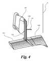
[0027]図4は、推進機/エジェクタ200が、もう1つのエアフォイル1000との組み合わせにおける、そして図3中に図示されている操縦表面の外形状からは異なった外形状である操縦表面1500の前にもまた置かれてよいことを図示している。図示されている実施形態においては、操縦表面1500の前縁1501は、エアフォイル1000の前縁1001に関して略90°角で配置されている。エジェクタ200は非線対称であって良く、そして、操縦表面は前記エジェクタ200の通り跡(wake)中に正に置かれ得る。エジェクタ200は、より熱い動力となるストリーム600(図1)を高い引き込み(entrainment)率で流入している冷たい周囲の空気のストリームと力強く混合する。同様に、この混合はエジェクタ温度の熱い動力となるストリーム600を機械的に又は構造的に操縦表面1500に否定的な影響を与えない混合温度プロファイル800へと減少させるのに十分に均質である。この実施形態においては、ヨーが、操縦表面1500の向きを変更させることにより制御することができる。同様なやり方で、そして、航空機胴体のような、乗り物本体に関する操縦表面1500の向きを変化させることにより、ピッチ及びロールが同様に制御され得る。エジェクタ200の機能は推力を発生させることであり、しかし、それはまた揚力又は高度制御を提供することができる。この実施形態においては、ヨー制御は、方向151において航空機軸10の回りの回転を創出する。 [0027] FIG. 4 shows the
[0028]図5は、推力を創出するために航空機の翼上にジェットエンジンを載置する従来の方法の代わりを提供する一実施形態を図示している。図5においては、ガス発生機501が、一次エアフォイルの後縁からガスストリームを直接的に噴出することによる前方への推進のために、翼503のような、一次エアフォイル中に埋設されている、一連のエジェクタ502を動かすための原動力となる空気の流れを創出する。この実施形態においては、ガス発生機501は、航空機の本体胴体504中に埋設されていて、導管505を介しエジェクタ502へと流体的に結合されていて、そして航空機の推進の唯一の手段である。エジェクタ502は円形又は図2中に図示されていた実施形態のように非円形であって良く、終端101と同様な対応している形状の出口構造を有し、そして、所定の調節可能な速度で、発生機501及び導管505からガスストリームを提供する。さらにエジェクタ502は、フラップ又はエルロンの方法と同様な方法で移動可能であって良く、180°角を通して回転可能であり、そして、所望の推進力を提供することに加え航空機の高度を制御するために動作されることができる。前縁507を有している第2エアフォイル506が、エジェクタ502からのガスストリームが第2エアフォイル506上を流れるよう、翼503と縦一列に並びそしてエジェクタ502の直後に置かれている。第2エアフォイル506が従って、航空機の対気速度よりも遥かに高い速度を受け、そして、対気速度の二乗に比例した高い揚力を創出する。第2エアフォイル506の全体は、前縁507に対し平行に向けられている軸の回りに回転可能であり得る。 [0028] FIG. 5 illustrates an embodiment that provides an alternative to the conventional method of mounting a jet engine on the wing of an aircraft to create thrust. In FIG. 5, the gas generator 501 is embedded in the primary airfoil, such as the
[0029]本発明のこの実施形態においては、第2エアフォイル506は、ガス発生機501により創出された原動力となる流体(また、一次流体として引用されている)及び個々の一次流体パーツ当たり第2流体が5〜25パーツの間の割合で原動力となる流体により引き込まれている第2流体の混合により、適度により高い温度と会う。このようであるので、第2エアフォイル506が会う温度は、周囲温度よりもわずかに高く、しかし、式:Tmix=(Tmotive+ER*Tamb)/(1+ER)に従って、揚力を支持し、そして維持する第2翼の材料を許容している、原動力となる流体よりは非常に低く、ここでTmixはエジェクタ502から噴出されているジェット流出の最終流体混合温度であり、ERは原動力となる空気の1パーツ当たりに引き込まれた大気の複数パーツの引き込み率であり、Tmotiveは原動力となる又は一次流体のより高い温度であり、そしてTambは接近している大気温度である。[0029] In this embodiment of the invention, the second airfoil 506 is the driving fluid (also cited as the primary fluid) created by the gas generator 501 and the first per individual primary fluid part. The mixing of the second fluid, in which the two fluids are drawn by the driving fluid at a ratio between 5 and 25 parts, meets a moderately higher temperature. As such, the temperature at which the second airfoil 506 meets is slightly higher than the ambient temperature, butsupports lift according to the formula: T mix = (Tfluid + ER*Tamb ) / (1 + ER). And much lower than the driving fluid, which allows the material of the second wing to be maintained, where Tmix is the final fluid mixing temperature of the jet outflow ejected from the
[0030]図6は、代わりの実施形態に従う、乗り物700のための推進システムを図示している。第1増強(augmenting)エアフォイル702は、乗り物700に結合されていて、そして、乗り物の一次エアフォイル701上を流れている流体の下流に位置されている。エアフォイル702は、軸707の回りを回転するよう構成されていて、アクチュエータ708により制御されている。図7中に最も良く図示されているように、第1増強エアフォイル702は、対向ノズル表面705,706のような第1出力構造、及び、ノズル表面により規定されている終端703と流体連通している、プレナム(plenum)704のような、少なくとも1つの導管を含む。ノズル表面705,706は、図1を参照して上で議論されていたノズル203と同様なノズルを含んで良いし含まなくとも良い。さらには、ノズル表面705,706の1つ又はそれ以上が、結果として、コアンダ(Coanda)効果を促進させることができ、そして、鋭い又は険しい隅を伴っていない連続して丸められている表面を有し得る凸状表面(convex surface)を含んで良い。プレナム704には、例えば、乗り物700により採用されて良い燃焼を基礎としているエンジンからの周囲より熱い空気(即ち、加圧されている原動力となるガスストリーム)が供給されている。プレナム704は、このガスストリームを終端703へと導くよう形作られており、終端703は一次エアフォイル701に向かう、そして第1増強エアフォイル702の外へのガスストリームのための出口を提供するよう構成されている。 [0030] FIG. 6 illustrates a propulsion system for
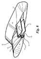
[0031]図8〜9を参照すると、一実施形態がエアフォイル702と同様な第2増強(augmenting)エアフォイル902を含んで良く、夫々は他の後縁から分岐している個々の後縁714,914を伴っている。より詳細には、第2増強エアフォイル902は乗り物700に結合されていて、そして、乗り物の一次エアフォイル701上を流れている流体の下流に位置されている。エアフォイル902は、エアフォイル702を参照して上で議論されていたのと同様な方法で回転するよう構成されている。エアフォイル902は、対向ノズル表面905,906のような第1出力構造及びノズル表面により規定されている終端903と流体連結されているプレナム(plenum)904のような少なくとも1つの導管を含んでいる。ノズル表面905,906は、図1を参照して上で議論されていたノズル203と同様なノズルを含んで良いし、含まなくても良い。さらには、ノズル表面905,906の1つ又はそれ以上が、結果として、コアンダ(Coanda)効果を促進させることが出来る凸状表面を含んで良い。プレナム904には、例えば、乗り物700により採用されて良い燃焼を基にしているエンジンからの周囲より熱い空気(即ち、加圧されている原動力となるガスストリーム)が供給される。プレナム904は、このガスストリームを終端903へと導くよう構成されていて、終端903は、一次エアフォイル701に向かう、そして第2増強エアフォイル902の外へのガスストリームのための出口を提供するよう構成されている。 [0031] With reference to FIGS. 8-9, one embodiment may include a second augmenting airfoil 902 similar to the
[0032]第1及び第2増強エアフォイル702,902は一次エアフォイルに向かい配置されている前縁716,916を有していて、第1増強エアフォイルは第2増強エアフォイルと対向している。動作においては、第1及び第2増強エアフォイル702,902が、それらの間にそしてそれらの長さに沿い、ここにおいて上で議論されていた拡散機210と機能において同様である、拡散領域802を規定している。前縁716,916は、プレナム704,904からのガスストリーム及び一次エアフォイル701上を流れている流体を受け、そして拡散領域802へと導くよう構成されている吸込み領域804を規定している。拡散領域802は、導入されたガスストリーム及び一次エアフォイル701上を流れている流体のための拡散領域からの出口を提供するよう構成されている一次終端806を含む。 [0032] The first and second augmented airfoil 702,902 have leading edges 716,916 located facing the primary airfoil, with the first augmented airfoil facing the second augmented airfoil. There is. In operation, the first and second augmented airfoil 702,902 are similar in function to the
[0033]図10は、縦一列に並んでいる翼を特徴としている、本発明の別の実施形態を描いている。図示されている実施形態においては、二次エアフォイル1010が、増強エアフォイル702,902の下流直後に置かれていて、一次エアフォイル701上を流れている流体及びこれらエアフォイルからのガスストリームが第2エアフォイル上を流れるようにしている。2つの比較的より短い翼701,702の組み合わせは、増強エアフォイル702,902を欠いている遥かにより大きなスパンの翼の揚力及び推力を創出するようにより大きな翼に対し取り付けられているジェットエンジンに依存する揚力よりもより大きな揚力を創出する。 [0033] FIG. 10 depicts another embodiment of the invention, characterized by vertical rows of wings. In the illustrated embodiment, the secondary airfoil 1010 is placed immediately downstream of the augmented airfoil 702,902, with the fluid flowing over the
[0034]前述のテキストは、多数の異なる実施形態の詳細な説明について説明しているが、保護の範囲は後に続く特許請求の範囲の文言によって定義されることが理解されるべきである。詳細な説明は、例示的にすぎないと解釈されるべきであり、あらゆる可能な実施形態について説明することは、実行不可能な場合、非実用的であるので、あらゆる可能な実施形態について説明するものではない。多数の代替実施形態が、現在の技術または本特許の出願日以降に開発される技術のどちらかを使用して実施可能であり、依然として特許請求の範囲に含まれる。 [0034] Although the aforementioned text describes a detailed description of a number of different embodiments, it should be understood that the scope of protection is defined by the wording of the claims that follow. The detailed description should be construed as merely exemplary and all possible embodiments will be described as it is impractical if infeasible to describe all possible embodiments. It's not a thing. A number of alternative embodiments can be implemented using either current technology or technology developed after the filing date of this patent and are still within the scope of the claims.
[0035]したがって、多数の修正および変形が、本特許請求の範囲の趣旨および範囲から逸脱することなく、本明細書において説明および図示される技法および構造においてなされ得る。したがって、本明細書において説明される方法および装置は例示にすぎず、特許請求の範囲を限定するものではないことが理解されるべきである。
以下に、本願出願の当初の特許請求の範囲に記載された発明を付記する。
[1] 外部を所定の調節可能な速度で推進流体が流れる出口構造を備えるエジェクタと、そして、
前縁を有し、そして、上をエジェクタからの推進流体が流れるよう出口構造の下流直後に配置されている第1操縦表面と、
を備える乗り物に結合される推進システム。
[2] 前記システムの動作の間、エジェクタからの推進流体のみが前記操縦表面上を流れる、[1]に記載の推進システム。
[3] 拡散構造と、
拡散構造に結合され、そして、乗り物により創出された一次流体を拡散構造へと導入するよう構成される少なくとも1つの導管と、
拡散構造に結合され、そして、乗り物に対し利用しやすく二次流体を拡散構造へと導入するよう構成される吸込み構造と、
をエジェクタがさらに備え、
ここにおいて、拡散構造が前記出口構造を備え、そして、前記推進流体が前記一次及び二次流体を含む、
[1]に記載の推進システム。
[4] エジェクタが凸状表面をさらに備え、
前記拡散構造が凸状表面に結合され、そして、
少なくとも1つの導管が前記凸状表面に結合されるとともに、前記一次流体を前記凸状表面へと導入するよう構成される、
[3]に記載の推進システム。
[5] 前記操縦表面の全体が前記前縁に対し平行に向く軸の回りに回転可能である、[1]に記載の推進システム。
[6] 前記出口構造が非対称である、[1]に記載の推進システム。
[7] 前記出口構造が第1及び第2側方対向縁を備え、そして、
前記第1側方対向縁が前記第2側方対向縁よりも大きな曲率半径を有する、
[6]に記載の推進システム。
[8] 前縁を有しているとともに乗り物に直接結合される第2操縦表面をさらに備え、
ここにおいて、前記第1操縦表面の前記前縁が前記第2操縦表面の前記前縁に対し非零角度であるよう前記第1操縦表面が前記第2操縦表面に対し結合される、
[1]に記載の推進システム。
[9] 本体と、
前記本体に対し結合される一次エアフォイルと、
前記本体に対し結合され、そして、ガスストリームを創出しているガス発生機と、
前記発生機に対し流体的に結合される導管と、
前記導管に対し流体的に結合され、そして、前記一次エアフォイル中に埋設され、その外を所定の調節可能な速度でガスストリームが流れる出口構造を備える、エジェクタと、そして、
前縁を有するとともに、エジェクタからのガスストリームが前記前縁上を流れるよう前記出口構造の下流直後に配置される二次エアフォイルと、
を備える乗り物。
[10] 前記ガス発生機が前記本体中に配置される、[9]に記載の乗り物。
[11] 前記一次エアフォイルが後縁を備え、そして、少なくとも1つの前記エジェクタが前記一次エアフォイルの後縁から直接的にガスストリームを噴出する、[9]に記載の乗り物。
[12] 前記発生機により創出されたガスストリームが前記乗り物の推進の唯一の手段である、[9]に記載の乗り物。
[13] 前記二次エアフォイルの全体が前記前縁に対し平行に向く軸の回りに回転可能である、[9]に記載の乗り物。
[14] 前記エジェクタが180°角に亘って回転可能である、[9]に記載の乗り物。
[15] 前記出口構造が非円形である、[9]に記載の乗り物。
[16] 乗り物のための推進システムであって、
前記乗り物に対し結合される一次エアフォイルと、
前記乗り物に対し結合されるとともに前記一次エアフォイル上を流れる流体の下流に位置する第1増強エアフォイルと、そして、
第1増強エアフォイルの下流直後に配置される二次エアフォイルと、
を備え、
前記第1増強エアフォイルが、第1出力構造及び第1出力構造に結合される少なくとも1つの第1導管を備え、前記少なくとも1つの第1導管は前記乗り物により創出された一次流体を第1出力構造へと導くよう構成され、前記第1出力構造は、前記一次エアフォイルに向かい、そして前記第1増強エアフォイルの外部へ導入された一次流体のための出口を提供するよう構成される第1終端を備え、
前記二次エアフォイルは前記一次エアフォイル上を流れる流体及び前記第1増強エアフォイルからの前記一次流体が前記二次エアフォイル上を流れる、
推進システム。
[17] 前記乗り物に対し結合され、前記一次エアフォイル上を流れる流体の下流に位置する第2増強エアフォイルをさらに備え、
前記第1及び第2増強エアフォイルの夫々は前記一次エアフォイルに向かって配置される前縁を有し、前記第1増強エアフォイルは前記第2増強エアフォイルに対向し、これにより、
前記第1及び第2増強エアフォイルは拡散領域を規定し、そして、
前記前縁は前記一次流体及び前記一次エアフォイル上を流れる流体を受け、そして前記拡散領域へと導くよう構成される入口領域を規定し、
前記拡散領域は、導入された一次流体及び前記一次エアフォイル上を流れる流体を混合し前記二次エアフォイルへと提供するよう構成される一次終端を備える、
[16]に記載の推進システム。
[18] 前記第2増強エアフォイルが、第2出力構造及び第2出力構造に結合される少なくとも1つの第2導管を備え、前記少なくとも1つの第2導管は前記乗り物により創出された一次流体を第2出力構造へと導くよう構成され、前記第2出力構造は、前記一次エアフォイルに向かい、そして前記第2増強エアフォイルの外への前記導入された一次流体のための出口を提供するよう構成される第2終端を備える、
[17]に記載の推進システム。
[19] 前記乗り物に対し前記第1増強エアフォイルを回転するよう構成される第1アクチュエータをさらに備える、[16]に記載の推進システム。
[20] 前記乗り物に対し前記第2増強エアフォイルを回転するよう構成される第2アクチュエータをさらに備える、[17]に記載の推進システム。[0035] Thus, numerous modifications and modifications can be made in the techniques and structures described and illustrated herein without departing from the spirit and scope of the claims. Therefore, it should be understood that the methods and devices described herein are merely exemplary and do not limit the scope of the claims.
The inventions described in the claims of the original application of the present application are described below.
[1] An ejector having an outlet structure through which a propulsion fluid flows at a predetermined adjustable speed, and an ejector.
With a first maneuvering surface that has a leading edge and is located just downstream of the outlet structure to allow the propulsion fluid from the ejector to flow over it.
A propulsion system that is coupled to a vehicle equipped with.
[2] The propulsion system according to [1], wherein only the propulsion fluid from the ejector flows on the control surface during the operation of the system.
[3] Diffusion structure and
With at least one conduit that is coupled to the diffusion structure and configured to introduce the primary fluid created by the vehicle into the diffusion structure.
A suction structure that is coupled to the diffusion structure and is configured to be accessible to the vehicle and introduce the secondary fluid into the diffusion structure.
Is further prepared by the ejector,
Here, the diffusion structure comprises the outlet structure and the propulsion fluid includes the primary and secondary fluids.
The propulsion system according to [1].
[4] The ejector further has a convex surface,
The diffusion structure is bonded to the convex surface and
At least one conduit is configured to be coupled to the convex surface and to introduce the primary fluid into the convex surface.
The propulsion system according to [3].
[5] The propulsion system according to [1], wherein the entire control surface is rotatable around an axis that faces parallel to the leading edge.
[6] The propulsion system according to [1], wherein the outlet structure is asymmetric.
[7] The outlet structure comprises first and second side facing edges, and
The first laterally opposed edge has a larger radius of curvature than the second laterally opposed edge.
The propulsion system according to [6].
[8] Further provided with a second maneuvering surface that has a leading edge and is directly coupled to the vehicle.
Here, the first maneuvering surface is coupled to the second maneuvering surface so that the leading edge of the first maneuvering surface is at a non-zero angle with respect to the leading edge of the second maneuvering surface.
The propulsion system according to [1].
[9] With the main body
The primary airfoil coupled to the body and
With a gas generator that is coupled to the body and creates a gas stream,
A conduit that is fluidly coupled to the generator
An ejector and an ejector having an outlet structure that is fluidly coupled to the conduit and embedded in the primary airfoil and through which a gas stream flows at a predetermined adjustable rate.
A secondary airfoil that has a leading edge and is arranged immediately downstream of the outlet structure so that the gas stream from the ejector flows over the leading edge.
Vehicles equipped with.
[10] The vehicle according to [9], wherein the gas generator is arranged in the main body.
[11] The vehicle according to [9], wherein the primary airfoil has a trailing edge, and at least one of the ejectors ejects a gas stream directly from the trailing edge of the primary airfoil.
[12] The vehicle according to [9], wherein the gas stream created by the generator is the only means of propelling the vehicle.
[13] The vehicle according to [9], wherein the entire secondary airfoil is rotatable about an axis oriented parallel to the leading edge.
[14] The vehicle according to [9], wherein the ejector is rotatable over a 180 ° angle.
[15] The vehicle according to [9], wherein the exit structure is non-circular.
[16] A propulsion system for vehicles
With the primary airfoil coupled to the vehicle,
A first augmented airfoil that is coupled to the vehicle and located downstream of the fluid flowing over the primary airfoil, and
A secondary airfoil placed immediately downstream of the first augmented airfoil, and
With
The first augmented airfoil comprises a first power structure and at least one first conduit coupled to the first power structure, the at least one first conduit first outputting the primary fluid created by the vehicle. A first configured to lead to a structure, the first output structure directed towards the primary airfoil and providing an outlet for a primary fluid introduced out of the first augmented airfoil. With termination,
In the secondary airfoil, the fluid flowing on the primary airfoil and the primary fluid from the first augmented airfoil flow on the secondary airfoil.
Propulsion system.
[17] Further comprising a second augmented airfoil coupled to the vehicle and located downstream of the fluid flowing over the primary airfoil.
Each of the first and second augmented airfoil has a leading edge that is located towards the primary airfoil, whereby the first augmented airfoil faces the second augmented airfoil, thereby.
The first and second augmented airfoil define a diffusion region and
The leading edge defines an inlet region configured to receive the primary fluid and the fluid flowing over the primary airfoil and guide it to the diffusion region.
The diffusion region comprises a primary termination configured to mix the introduced primary fluid and the fluid flowing over the primary airfoil and provide it to the secondary airfoil.
The propulsion system according to [16].
[18] The second augmented airfoil comprises a second power structure and at least one second conduit coupled to the second power structure, the at least one second conduit containing the primary fluid created by the vehicle. Configured to lead to a second power structure, the second power structure is directed towards the primary airfoil and provides an outlet for the introduced primary fluid out of the second augmented airfoil. With a second termination configured,
The propulsion system according to [17].
[19] The propulsion system according to [16], further comprising a first actuator configured to rotate the first augmented airfoil with respect to the vehicle.
[20] The propulsion system according to [17], further comprising a second actuator configured to rotate the second augmented airfoil with respect to the vehicle.
Claims (18)
Translated fromJapanese所定の調節可能な速度で推進流体が流れ出る出口構造を備えるエジェクタと、前記エジェクタは、拡散構造と、前記拡散構造に結合され、乗り物により創出された一次流体を前記拡散構造へと導入するよう構成される少なくとも1つの導管と、前記拡散構造に結合され、周囲流体を前記拡散構造へと導入するよう構成される吸込み構造と、を備え、ここにおいて、前記拡散構造は前記出口構造を備え、そして、前記推進流体は前記一次及び周囲流体を含む、そして、
上面および下面並びに前記エジェクタに対して軸方向に延出する平面に位置合わせされた前縁を有する第1操縦表面と、前記第1操縦表面は、他の周囲流体を除き、前記エジェクタからの推進流体が前記上面および下面を流れるように前記出口構造の下流直後に配置されている、
を備える
推進システム。A propulsion system coupled to a vehicle,said propulsion system
An ejector having an outlet structure through which a propulsion fluid flows out at a predetermined adjustable rate, and theejector are configured to be coupled to a diffusion structure and the diffusion structure to introduce a primary fluid created by a vehicle into the diffusion structure. A suction structure that is coupled to the diffusion structure and is configured to introduce an ambient fluid into the diffusion structure, wherein the diffusion structure comprises an outlet structure and , The propulsion fluid includes the primary and ambient fluids, and
And upper and lower surfaces and first control surfaceto have a leading edgethat is aligned in a plane extending in the axial direction with respect to the ejector,the first steering surface, except for the other surrounding fluids, from the ejector The propulsion fluid is arranged immediately downstream of the outlet structure so that it flows through the upper and lower surfaces.
Propulsion systemequipped with.
前記拡散構造が前記凸状表面に結合され、そして、
前記少なくとも1つの導管が前記凸状表面に結合されるとともに、前記一次流体を前記凸状表面へと導入するよう構成される、
請求項1に記載の推進システム。The ejector further comprises a convex surface
The diffusion structure is bonded to the convex surface and
The at least one conduit is configured to be coupled to the convex surface and to introduce the primary fluid into the convex surface.
The propulsion system according to claim 1.
前記第1側方対向縁が前記第2側方対向縁よりも大きな曲率半径を有する、
請求項4に記載の推進システム。The outlet structure comprises first and second side facing edges, and
The first laterally opposed edge has a larger radius of curvature than the second laterally opposed edge.
The propulsion system according to claim 4.
ここにおいて、前記第1操縦表面の前記前縁が前記第2操縦表面の前記前縁に対し零でない角度であるよう前記第1操縦表面が前記第2操縦表面に対し結合される、
請求項1に記載の推進システム。Further provided with a second maneuvering surface that has a leading edge and is directly coupled to the vehicle.
Here, the first maneuvering surface is coupled to the second maneuvering surface so that the leading edge of the first maneuvering surface is at a non-zero angle with respect to the leading edge of the second maneuvering surface.
The propulsion system according to claim 1.
前記本体に対し結合される一次エアフォイルと、
前記本体に対し結合され、そして、ガスストリームを創出しているガス発生機と、
前記発生機に対し流体的に結合される導管と、
前記導管に対し流体的に結合され、そして、前記一次エアフォイル中に埋設され、所定の調節可能な速度で前記ガスストリームが流れ出る出口構造を備える、エジェクタと、そして、
前記一次エアフォイルから離れており、そして、前縁を有するとともに、前記エジェクタからの前記ガスストリームが二次エアフォイルの前記前縁上を流れるよう前記出口構造の下流直後に配置される前記二次エアフォイルと、
を備える、乗り物。With the main body
The primary airfoil coupled to the body and
With a gas generator that is coupled to the body and creates a gas stream,
A conduit that is fluidly coupled to the generator
An ejector and an ejector having an outlet structure that is fluidly coupled to the conduit and embedded in the primary airfoil to allow the gas stream to flow out at a predetermined adjustable rate.
The secondary, which is separated from the primary airfoil and has a leading edge and is arranged immediately downstream of the outlet structure so that the gas stream from the ejector flows over the leading edge of the secondary airfoil. With airfoil,
A vehicle equipped with.
前記乗り物に対し結合される一次エアフォイルと、
前記乗り物に対し結合されるとともに前記一次エアフォイル上を流れる流体の下流に位置する第1増強エアフォイルと、そして、
前記第1増強エアフォイルから離れた二次エアフォイルと、
を備え、
前記第1増強エアフォイルは、第1出力構造及び前記第1出力構造に結合される少なくとも1つの第1導管を備え、前記少なくとも1つの第1導管は前記乗り物により創出された一次流体を前記第1出力構造へと導入するよう構成され、前記第1出力構造は、前記一次エアフォイルに向かい、そして前記第1増強エアフォイルから出る前記導入された一次流体のための出口を提供するよう構成される第1終端を備え、
前記二次エアフォイルは前記一次エアフォイル上を流れる前記流体及び前記第1増強エアフォイルからの前記一次流体が前記二次エアフォイル上を流れるように、前記第1増強エアフォイルの下流直後に配置される、
推進システム。A propulsion system for vehicles
With the primary airfoil coupled to the vehicle,
A first augmented airfoil that is coupled to the vehicle and located downstream of the fluid flowing over the primary airfoil, and
With the secondary airfoil away from the first augmented airfoil,
With
The first augmented airfoil comprises a first power structure and at least one first conduit coupled to the first power structure, the at least one first conduit comprising a primary fluid created by the vehicle. Configured to introduce into a one-power structure, the first-power structure is configured to provide an outlet for the introduced primary fluid towards the primary airfoil and out of the first augmented airfoil. With a first termination
The secondary airfoil is arranged immediately downstream of the first augmented airfoil so that the fluid flowing over the primary airfoil and the primary fluid from the first augmented airfoil flow over the secondary airfoil. Be done,
Propulsion system.
前記第1及び第2増強エアフォイルの各々は前記一次エアフォイルに向かって配置される前縁を有し、前記第1増強エアフォイルは前記第2増強エアフォイルに対向し、これにより、
前記第1及び第2増強エアフォイルは拡散領域を規定し、そして、
前記前縁は前記一次流体及び前記一次エアフォイル上を流れる前記流体を受け、そして前記拡散領域へと導入するよう構成される吸込み領域を規定し、
前記拡散領域は、前記導入された一次流体及び前記一次エアフォイル上を流れる流体を混合し前記二次エアフォイルへと提供するよう構成される一次終端を備える、
請求項14に記載の推進システム。Further comprising a second augmented airfoil coupled to the vehicle and located downstream of the fluid flowing over the primary airfoil.
Each of the first and second augmented airfoil has a leading edge disposed towards the primary airfoil, wherein the first augmented airfoil faces the second augmented airfoil, thereby.
The first and second augmented airfoil define a diffusion region and
The leading edge defines a suction region configured to receive the primary fluid and the fluid flowing over the primary airfoil and introduce it into the diffusion region.
The diffusion region comprises a primary termination configured to mix the introduced primary fluid and the fluid flowing over the primary airfoil and provide it to the secondary airfoil.
The propulsion system according to claim 14.
請求項15に記載の推進システム。The second augmented airfoil comprises a second power structure and at least one second conduit coupled to the second power structure, wherein the at least one second conduit is the primary fluid created by the vehicle. It is configured to be introduced into a second output structure, the second output structure being configured to provide an outlet for the introduced primary fluid towards the primary airfoil and out of the second augmented airfoil. With a second termination to be
The propulsion system according to claim 15.
Applications Claiming Priority (3)
| Application Number | Priority Date | Filing Date | Title |
|---|---|---|---|
| US201562213465P | 2015-09-02 | 2015-09-02 | |
| US62/213,465 | 2015-09-02 | ||
| PCT/US2016/044326WO2017065858A2 (en) | 2015-09-02 | 2016-07-27 | Ejector and airfoil configurations |
Publications (2)
| Publication Number | Publication Date |
|---|---|
| JP2018532647A JP2018532647A (en) | 2018-11-08 |
| JP6930743B2true JP6930743B2 (en) | 2021-09-01 |
Family
ID=58097438
Family Applications (3)
| Application Number | Title | Priority Date | Filing Date |
|---|---|---|---|
| JP2018531293AActiveJP6930743B2 (en) | 2015-09-02 | 2016-07-27 | Ejector and airfoil shape |
| JP2018531294AActiveJP6885610B2 (en) | 2015-09-02 | 2016-07-27 | Fluid propulsion system |
| JP2018531300AActiveJP6964886B2 (en) | 2015-09-02 | 2016-09-02 | Fluid propulsion system and thrust and lift generator for aircraft |
Family Applications After (2)
| Application Number | Title | Priority Date | Filing Date |
|---|---|---|---|
| JP2018531294AActiveJP6885610B2 (en) | 2015-09-02 | 2016-07-27 | Fluid propulsion system |
| JP2018531300AActiveJP6964886B2 (en) | 2015-09-02 | 2016-09-02 | Fluid propulsion system and thrust and lift generator for aircraft |
Country Status (11)
| Country | Link |
|---|---|
| US (15) | US10800538B2 (en) |
| EP (7) | EP3344535B1 (en) |
| JP (3) | JP6930743B2 (en) |
| KR (5) | KR102668106B1 (en) |
| CN (3) | CN108137150B (en) |
| AU (5) | AU2016338383A1 (en) |
| CA (4) | CA2996284A1 (en) |
| ES (5) | ES2890927T3 (en) |
| IL (4) | IL257811B (en) |
| PL (1) | PL3363732T3 (en) |
| WO (3) | WO2017065858A2 (en) |
Families Citing this family (67)
| Publication number | Priority date | Publication date | Assignee | Title |
|---|---|---|---|---|
| US10562613B2 (en)* | 2013-12-04 | 2020-02-18 | Tamarack Aerospace Group, Inc. | Adjustable lift modification wingtip |
| US11965456B2 (en)* | 2015-09-02 | 2024-04-23 | Jetoptera, Inc. | Fluidic turbo heater system |
| USD856899S1 (en)* | 2017-11-10 | 2019-08-20 | Jetoptera, Inc. | Airframe for an unmanned aerial vehicle |
| US11001378B2 (en) | 2016-08-08 | 2021-05-11 | Jetoptera, Inc. | Configuration for vertical take-off and landing system for aerial vehicles |
| US10464668B2 (en)* | 2015-09-02 | 2019-11-05 | Jetoptera, Inc. | Configuration for vertical take-off and landing system for aerial vehicles |
| JP6930743B2 (en) | 2015-09-02 | 2021-09-01 | ジェトプテラ、インコーポレイテッド | Ejector and airfoil shape |
| KR101607816B1 (en)* | 2015-10-26 | 2016-03-31 | 이진우 | Drone with air guide part |
| CA3032441A1 (en)* | 2016-08-08 | 2018-02-15 | Jetoptera, Inc. | Internal combustion engine exhaust pipe fluidic purger system |
| CN107150788A (en)* | 2017-04-26 | 2017-09-12 | 朱晓义 | A kind of Fixed Wing AirVehicle for producing greater lift |
| JP7217272B2 (en)* | 2017-06-16 | 2023-02-02 | ジェトップテラ,インコーポレイテッド | Winglet ejector configuration |
| CN109716326A (en)* | 2017-06-21 | 2019-05-03 | 微软技术许可有限责任公司 | Personalized song is provided in automatic chatting |
| CA3068569A1 (en) | 2017-06-27 | 2019-01-03 | Jetoptera, Inc. | Configuration for vertical take-off and landing system for aerial vehicles |
| US20190061905A1 (en)* | 2017-08-30 | 2019-02-28 | David Victor Bosse, JR. | Airfoil |
| US11047874B1 (en)* | 2017-10-18 | 2021-06-29 | Government Of The United States As Represented By The Secretary Of The Air Force | System, apparatus and method for predicting aerodynamic parameters using artifical hair sensor array |
| CN108052118A (en)* | 2017-12-12 | 2018-05-18 | 中国联合网络通信集团有限公司 | A kind of unmanned vehicle control method and device |
| WO2019191237A1 (en)* | 2018-03-29 | 2019-10-03 | Walmart Apollo, Llc | Aerial vehicle turbine system |
| US10802507B2 (en)* | 2018-03-30 | 2020-10-13 | Ansel Misfeldt | Aerial vehicles and control therefor |
| JP7097052B2 (en)* | 2018-04-04 | 2022-07-07 | 国立研究開発法人宇宙航空研究開発機構 | Airplane gust response mitigation system and airplane gust response mitigation method |
| US10336452B1 (en)* | 2018-04-16 | 2019-07-02 | Muye Jia | Drone with no external propeller blades |
| RO133664B1 (en)* | 2018-04-17 | 2024-07-30 | Răzvan Sabie | Aircraft with vertical take-off and landing |
| CA3100545A1 (en)* | 2018-05-17 | 2019-11-21 | Jetoptera, Inc. | Combination compressed-fluid ejector and propeller propulsion system |
| IL319941A (en)* | 2018-05-29 | 2025-05-01 | Jetoptera Inc | Streamline airframe with boundary ingestion fluidic propulsive elements |
| USD894807S1 (en)* | 2018-06-14 | 2020-09-01 | Transportation Ip Holdings, Llc | Exhaust stack |
| PL426033A1 (en) | 2018-06-22 | 2020-01-02 | General Electric Company | Fluid steam jet pumps, as well as systems and methods of entraining fluid using fluid steam jet pumps |
| US10710741B2 (en) | 2018-07-02 | 2020-07-14 | Joby Aero, Inc. | System and method for airspeed determination |
| EP3853736A4 (en) | 2018-09-17 | 2022-11-16 | Joby Aero, Inc. | AIRCRAFT CONTROL SYSTEM |
| JP6609760B1 (en)* | 2018-09-22 | 2019-11-27 | 株式会社エアロネクスト | Flying object |
| CN113226925A (en)* | 2018-11-09 | 2021-08-06 | 杰托普特拉股份有限公司 | Adaptive vertical take-off and landing propulsion system |
| WO2020180373A2 (en) | 2018-12-07 | 2020-09-10 | Joby Aero, Inc. | Aircraft control system and method |
| TWI719373B (en)* | 2018-12-13 | 2021-02-21 | 研能科技股份有限公司 | Power driver of unmanned aerial vehicle |
| US12202604B2 (en)* | 2019-01-18 | 2025-01-21 | Jetoptera, Inc. | Vertical take off and landing aircraft with fluidic propulsion system |
| KR20210118416A (en)* | 2019-01-18 | 2021-09-30 | 제톱테라 잉크. | fluid propulsion system |
| US11440671B2 (en)* | 2019-01-24 | 2022-09-13 | Amazon Technologies, Inc. | Adjustable motor fairings for aerial vehicles |
| DE102019105355B4 (en)* | 2019-03-04 | 2024-04-25 | Ebm-Papst Mulfingen Gmbh & Co. Kg | Fan wheel of an axial fan |
| US12071228B1 (en)* | 2019-03-28 | 2024-08-27 | Snap Inc. | Drone with propeller guard configured as an airfoil |
| CN116646641B (en) | 2019-04-23 | 2024-09-13 | 杰欧比飞行有限公司 | Battery thermal management system and method |
| US11230384B2 (en)* | 2019-04-23 | 2022-01-25 | Joby Aero, Inc. | Vehicle cabin thermal management system and method |
| CN115335609A (en)* | 2019-08-19 | 2022-11-11 | 顶峰推进有限责任公司 | Thrust enhanced lift and propulsion system |
| EP4025496A1 (en)* | 2019-09-03 | 2022-07-13 | BAE SYSTEMS plc | Fluidic control |
| EP4025467A1 (en) | 2019-09-03 | 2022-07-13 | BAE SYSTEMS plc | Vehicle control |
| WO2021076250A2 (en)* | 2019-09-11 | 2021-04-22 | Alexandru Balan | 360° advanced rotation system |
| US11453488B2 (en) | 2019-09-30 | 2022-09-27 | Rolls-Royce Corporation | Lightweight parallel combustion lift system for vertical takeoff aircraft |
| CA3155991A1 (en)* | 2019-11-01 | 2021-05-06 | Andrei Evulet | Fluidic turbo heater system |
| US11299284B2 (en)* | 2019-12-11 | 2022-04-12 | Zhenkun Wang | Airplane providing enhanced aviation and a method to enhance aviation thereof |
| US10837402B2 (en)* | 2020-01-09 | 2020-11-17 | Guanhao Wu | Thrust vector nozzle |
| CN111504129B (en)* | 2020-04-10 | 2022-10-21 | 中国航天空气动力技术研究院 | A kind of airborne laser pneumatic ejection structure and method |
| WO2021242463A2 (en)* | 2020-04-27 | 2021-12-02 | Jetoptera, Inc. | Vertical take off and landing aircraft with fluidic propulsion system |
| US12040730B2 (en)* | 2020-05-21 | 2024-07-16 | The Boeing Company | Active flow control systems and methods for aircraft |
| CN112399786B (en)* | 2020-11-19 | 2022-12-13 | 杭州顾忠科技有限公司 | Electronic information anti-interference device |
| CN112373702B (en)* | 2020-11-24 | 2022-07-05 | 中国航空发动机研究院 | Back-support type wing-body fusion body aircraft propulsion system and control method thereof |
| KR20220092064A (en) | 2020-12-24 | 2022-07-01 | 현대자동차주식회사 | Auxiliary propulsion device for aircraft |
| CN113602478B (en)* | 2021-02-02 | 2023-06-13 | 中国空气动力研究与发展中心高速空气动力研究所 | Fluid control surface based on circulation control and vertical micro-jet flow |
| CA3219575A1 (en)* | 2021-05-19 | 2022-12-01 | Jetoptera, Inc. | Adaptive fluidic propulsive system |
| US11148795B1 (en)* | 2021-07-02 | 2021-10-19 | Choudary Ramakrishna Bobba | Radial airfoil and lift disc |
| CN113291459B (en)* | 2021-07-27 | 2021-11-30 | 中国空气动力研究与发展中心高速空气动力研究所 | Distributed ducted fan high-lift system and application method thereof |
| US12338008B2 (en)* | 2021-09-17 | 2025-06-24 | Singapore University Of Technology And Design | Monocopter |
| US11781441B2 (en)* | 2021-12-30 | 2023-10-10 | Hamilton Sundstrand Corporation | Air cycle machine with separate compressor and turbine and fan and turbine |
| US12024285B1 (en) | 2022-03-10 | 2024-07-02 | Skypad Tech, Inc. | Modular mobility system including thrusters movably connected to a support structure |
| US11808216B1 (en) | 2022-06-10 | 2023-11-07 | Rolls-Royce North American Technologies Inc. | Air-provisioning system with ejectors |
| CN114996851B (en)* | 2022-06-14 | 2024-05-24 | 南京航空航天大学 | Experiment table design method for simulating boundary layer leakage flow and subsonic outflow coupling |
| US12145753B2 (en)* | 2022-08-09 | 2024-11-19 | Pete Bitar | Compact and lightweight drone delivery device called an ArcSpear electric jet drone system having an electric ducted air propulsion system and being relatively difficult to track in flight |
| EP4415006B1 (en)* | 2023-02-13 | 2025-09-10 | Hitachi Energy Ltd | An airflow generator |
| EP4421832A1 (en)* | 2023-02-21 | 2024-08-28 | Hitachi Energy Ltd | A transformer arrangement |
| KR102767406B1 (en)* | 2023-07-11 | 2025-02-14 | (주)창인에이비에이션 | Lift device for Aircraft |
| TWM657368U (en)* | 2023-11-20 | 2024-07-01 | 台灣飛行器股份有限公司 | Unmanned aerial device |
| CN118094958B (en)* | 2024-04-19 | 2024-07-16 | 中南大学 | A Design Method for Simplified Model of Fluidic Oscillator |
| CN119389424B (en)* | 2024-10-25 | 2025-09-09 | 北京航空航天大学 | Airfoil wave water surface environment lift and stability increasing control method based on circulation control technology |
Family Cites Families (758)
| Publication number | Priority date | Publication date | Assignee | Title |
|---|---|---|---|---|
| US3216653A (en) | 1962-07-09 | 1965-11-09 | Bertin & Cie | Ejectors and piping systems operating with a divergent fluid wall |
| US1495185A (en) | 1922-08-18 | 1924-05-27 | Ingersoll Rand Co | Jet augmenter or ejector |
| US1821468A (en) | 1928-04-16 | 1931-09-01 | Hanley John | Mixing device |
| US1891166A (en)* | 1931-05-23 | 1932-12-13 | Leupold Mathias | Tilting-engine wing plane |
| GB431646A (en)* | 1934-01-08 | 1935-07-08 | Henri Coanda | Improvements in or relating to the propulsion of solid bodies in fluid media |
| US2052869A (en) | 1934-10-08 | 1936-09-01 | Coanda Henri | Device for deflecting a stream of elastic fluid projected into an elastic fluid |
| US2593420A (en) | 1946-05-28 | 1952-04-22 | Walter S Diehl | Variable area nozzle |
| US2684817A (en) | 1947-07-21 | 1954-07-27 | Snecma | Aircraft powered by ramjet units |
| US2585676A (en) | 1947-07-31 | 1952-02-12 | Poisson-Quinton Philippe | Aircraft wing and flap with boundary layer control |
| US2946540A (en)* | 1948-09-13 | 1960-07-26 | Sebac Nouvelle Sa | Jet propelled aircraft |
| BE525114A (en) | 1952-12-16 | |||
| US2928238A (en)* | 1953-06-08 | 1960-03-15 | Lockheed Aircraft Corp | Jet deflector and orifice control |
| DE1024364B (en) | 1953-09-07 | 1958-02-13 | Power Jets Res & Dev Ltd | Transverse drive surface, in particular aircraft wings |
| US2870600A (en) | 1954-12-27 | 1959-01-27 | Charles R Brown | Variable ejector for iris nozzles |
| NL110393C (en) | 1955-11-29 | 1965-01-15 | Bertin & Cie | |
| US2885162A (en) | 1956-02-08 | 1959-05-05 | Elizabeth M Griswold | Integrated jet-wing |
| US2988303A (en) | 1956-07-24 | 1961-06-13 | Sebac Nouvelle Sa | Jet sustained aircraft |
| BE560119A (en) | 1956-09-13 | |||
| US2989845A (en) | 1957-12-02 | 1961-06-27 | Curtiss Wright Corp | Converging-diverging nozzle construction |
| US3045947A (en) | 1959-04-24 | 1962-07-24 | Bertin & Cie | Ejectors, particularly for producing lift in aircraft |
| US3028121A (en) | 1959-11-27 | 1962-04-03 | Gen Electric | Thrust augmenting means for aircraft |
| US3051413A (en)* | 1960-03-18 | 1962-08-28 | Pouit Robert | Vtol aircraft |
| NL262125A (en) | 1960-04-01 | |||
| US3055614A (en)* | 1960-05-12 | 1962-09-25 | Wendell J Thompson | Air-ejector aircraft |
| US3085770A (en) | 1960-09-22 | 1963-04-16 | Lockheed Aircraft Corp | Aircraft propulsion system |
| US3116041A (en) | 1961-02-10 | 1963-12-31 | Lockheed Aircraft Corp | Aircraft propulsion distribution system |
| FR1318816A (en) | 1962-01-13 | 1963-02-22 | Aviation Louis Breguet Sa | Vertical or short take-off and landing aircraft |
| US3154267A (en) | 1962-03-13 | 1964-10-27 | Charles H Grant | Controlled temperature flow around airfoils |
| DE1292006B (en)* | 1962-11-09 | 1969-04-03 | Siebelwerke Atg Gmbh | Airplane with jet propulsion and jet control |
| US3337121A (en) | 1964-07-22 | 1967-08-22 | Huyck Corp | Fluid propulsion system |
| US3318097A (en) | 1964-10-12 | 1967-05-09 | Garrett Corp | Air mass flow multiplier for thrust augmentation |
| US3326500A (en) | 1964-11-25 | 1967-06-20 | Edward M Lanier | Aircraft lift-increasing device |
| US3330500A (en)* | 1965-03-22 | 1967-07-11 | Ltv Aerospace Corp | Propulsive wing airplane |
| US3347495A (en) | 1965-05-17 | 1967-10-17 | Boeing Co | Airplane wing flap with augmented jet lift-increasing device |
| US3392529A (en) | 1965-07-23 | 1968-07-16 | Rolls Royce | Aircraft provided with a gas turbine vertical lift engine |
| US3370794A (en) | 1965-11-08 | 1968-02-27 | Navy Usa | Annular plenum nozzle for controlling trajectory of rockets |
| US3396538A (en) | 1966-10-03 | 1968-08-13 | United Aircraft Corp | Water injection for thrust augmentation |
| US3441218A (en) | 1966-11-07 | 1969-04-29 | Paul Bucher | Adjustable nozzle for jet propulsion engine |
| FR94023E (en) | 1967-05-24 | 1969-06-20 | Bertin & Cie | Lift system or propulsion lift for aircraft. |
| US3525474A (en) | 1968-12-09 | 1970-08-25 | Us Air Force | Jet pump or thrust augmentor |
| US3664611A (en) | 1969-12-17 | 1972-05-23 | Flight Dynamics Res | Aerodynamic vehicle |
| US3667680A (en) | 1970-04-24 | 1972-06-06 | Boeing Co | Jet engine exhaust nozzle system |
| FR2087976B1 (en)* | 1970-05-04 | 1973-03-16 | Bertin & Cie | |
| RO53910A2 (en) | 1970-10-26 | 1973-09-20 | ||
| US3722454A (en) | 1970-10-28 | 1973-03-27 | R Silvester | Thrust augmenter |
| US3694107A (en) | 1970-11-19 | 1972-09-26 | Nash Engineering Co | Ejector apparatus and method of utilizing same |
| GB1332026A (en) | 1971-08-07 | 1973-10-03 | British Aircraft Corp Ltd | Aircraft |
| US3887146A (en) | 1971-08-23 | 1975-06-03 | Univ Rutgers | Aircraft with combination stored energy and engine compressor power source for augmentation of lift, stability, control and propulsion |
| US3747874A (en)* | 1971-08-25 | 1973-07-24 | Rohr Corp | Ejector nozzle having primary nozzles communicating with exhaust gases in plenum chamber |
| US3770227A (en) | 1971-09-10 | 1973-11-06 | Us Air Force | Jet wing with multiple thrust augmentors |
| US3747855A (en) | 1972-03-01 | 1973-07-24 | Gen Electric | Propulsion nozzles |
| US3885891A (en) | 1972-11-30 | 1975-05-27 | Rockwell International Corp | Compound ejector |
| CA981918A (en)* | 1972-11-30 | 1976-01-20 | Lester W. Throndson | Compound ejector for high energy flow fluid |
| US3819134A (en) | 1972-11-30 | 1974-06-25 | Rockwell International Corp | Aircraft system lift ejector |
| US3834834A (en) | 1973-03-07 | 1974-09-10 | Us Air Force | Compact high thrust augmentation ejector system |
| US3829044A (en) | 1973-03-23 | 1974-08-13 | Lockheed Aircraft Corp | Engine arrangement for high performance stol aircraft |
| US3795367A (en) | 1973-04-05 | 1974-03-05 | Src Lab | Fluid device using coanda effect |
| US3879939A (en) | 1973-04-18 | 1975-04-29 | United Aircraft Corp | Combustion inlet diffuser employing boundary layer flow straightening vanes |
| US3878400A (en) | 1973-04-30 | 1975-04-15 | Gen Electric | Excitation control arrangement for diesel-electric propulsion systems |
| US3831887A (en) | 1973-06-28 | 1974-08-27 | Rockwell International Corp | Aircraft control methods |
| US3860200A (en)* | 1973-09-05 | 1975-01-14 | Rockwell International Corp | Airfoil |
| US3875745A (en) | 1973-09-10 | 1975-04-08 | Wagner Minning Equipment Inc | Venturi exhaust cooler |
| US4030289A (en) | 1973-10-29 | 1977-06-21 | Chandler Evans Inc. | Thrust augmentation technique and apparatus |
| US4019696A (en) | 1973-12-28 | 1977-04-26 | The Boeing Company | Method of and apparatus for enhancing Coanda flow attachment over a wing and flap surface |
| US3917193A (en)* | 1974-01-21 | 1975-11-04 | Boeing Co | Boundary layer control and anti-icing apparatus for an aircraft wing |
| US3893638A (en)* | 1974-02-14 | 1975-07-08 | Boeing Co | Dual cycle fan jet engine for stol aircraft with augmentor wings |
| US3926373A (en) | 1974-07-26 | 1975-12-16 | Us Air Force | Thrust augmentation system with oscillating jet nozzles |
| US3942463A (en) | 1974-10-01 | 1976-03-09 | The United States Of America As Represented By The Secretary Of The Navy | Movable ramp inlet for water jet propelled ships |
| US3920203A (en)* | 1974-12-23 | 1975-11-18 | Boeing Co | Thrust control apparatus for obtaining maximum thrust reversal in minimum time upon landing of an aircraft |
| GB1465412A (en)* | 1975-02-14 | 1977-02-23 | Coxon J | Aircraft |
| US3941335A (en) | 1975-06-19 | 1976-03-02 | The United States Of America As Represented By The Secretary Of The Air Force | Automatic boundary layer control in an ejector wing aircraft |
| US4332529A (en) | 1975-08-11 | 1982-06-01 | Morton Alperin | Jet diffuser ejector |
| US4030687A (en) | 1976-02-23 | 1977-06-21 | The Boeing Company | Articulated nozzle for upper surface blown aircraft |
| DK140426B (en)* | 1976-11-01 | 1979-08-27 | Arborg O J M | Propulsion nozzle for means of transport in air or water. |
| US4099691A (en)* | 1976-12-13 | 1978-07-11 | The Boeing Company | Boundary layer control system for aircraft |
| IL52613A (en) | 1977-07-28 | 1980-11-30 | Univ Ramot | Method and apparatus for controlling the mixing of two fluids |
| CA1100463A (en)* | 1978-11-22 | 1981-05-05 | Frederick L. Gilbertson | Nozzle structure with notches |
| US4398683A (en) | 1978-12-26 | 1983-08-16 | Schmetzer William M | Aircraft with thrust and lift augmenting airfoil |
| US4709880A (en)* | 1978-12-29 | 1987-12-01 | General Dynamics Corporation | Method and system for improved V/STOL aircraft performance |
| US4285482A (en)* | 1979-08-10 | 1981-08-25 | The Boeing Company | Wing leading edge high lift device |
| DE3014712A1 (en) | 1980-04-17 | 1981-10-22 | Robert Bosch Gmbh, 7000 Stuttgart | CONTROL DEVICE FOR STOPPING A DIESEL INTERNAL COMBUSTION ENGINE |
| GB2469613B (en)* | 1980-11-28 | 2011-03-23 | Rolls Royce Plc | Aircraft |
| US4398687A (en) | 1981-02-25 | 1983-08-16 | The United States Of America As Represented By The Secretary Of The Navy | Thrust deflector and force augmentor |
| US4392621A (en) | 1981-04-07 | 1983-07-12 | Hermann Viets | Directional control of engine exhaust thrust vector in a STOL-type aircraft |
| US4418352A (en) | 1981-05-18 | 1983-11-29 | Ricoh Company, Ltd. | Ink jet printing apparatus |
| DE3274535D1 (en)* | 1981-10-15 | 1987-01-15 | Aeritalia Spa | Aircraft with jet propulsion |
| IT1144840B (en)* | 1981-10-15 | 1986-10-29 | Aeritalia Spa | AIRCRAFT WITH JET PROPULSER USING A SINGLE-SIDED EJECTOR SYSTEM FOR INCREASING THE CARRIER AND THE THRUST |
| US4445338A (en) | 1981-10-23 | 1984-05-01 | The United States Of America As Represented By The Secretary Of The Navy | Swirler assembly for a vorbix augmentor |
| US4477039A (en) | 1982-06-30 | 1984-10-16 | Mcdonnell Douglas Corporation | Vented cowl variable geometry inlet for aircraft |
| US4448354A (en)* | 1982-07-23 | 1984-05-15 | The United States Of America As Represented By The Secretary Of The Air Force | Axisymmetric thrust augmenting ejector with discrete primary air slot nozzles |
| US4442986A (en)* | 1982-08-30 | 1984-04-17 | The United States Of America As Represented By The Secretary Of The Navy | Leading edge augmentor wing-in-ground effect vehicle |
| US4482108A (en)* | 1982-09-29 | 1984-11-13 | The Boeing Company | Tilt wing short takeoff aircraft and method |
| US4815942A (en) | 1982-10-25 | 1989-03-28 | Elayne P. Alperin | Axially-symmetric, jet-diffuser ejector |
| AU2443884A (en) | 1983-02-15 | 1984-08-23 | Commonwealth Of Australia, The | Thrust augmentor |
| US4641800A (en)* | 1983-08-18 | 1987-02-10 | Rutan Elbert L | Tandem or multi-winged high performance aircraft |
| US4645140A (en) | 1983-08-18 | 1987-02-24 | Rockwell International Corporation | Nozzle system |
| US4648571A (en) | 1984-07-19 | 1987-03-10 | Northrop Corporation | Transverse thrust lift augmentation system |
| US5035377A (en) | 1985-02-28 | 1991-07-30 | Technolizenz Establishment | Free standing or aircraft lift generator |
| US4796836A (en) | 1985-02-28 | 1989-01-10 | Dieter Schatzmayr | Lifting engine for VTOL aircrafts |
| USRE35387E (en) | 1985-04-09 | 1996-12-03 | Dynamic Engineering, Inc. | Superfragile tactical fighter aircraft and method of flying it in supernormal flight |
| US4666104A (en) | 1985-07-22 | 1987-05-19 | Kelber Charles C | Combination lift thrust device |
| JPS6257512A (en)* | 1985-08-14 | 1987-03-13 | インバネス・コ−ポレ−シヨン | Nail file, lubricant and filing method |
| JPH0660640B2 (en) | 1985-09-09 | 1994-08-10 | 清之 堀井 | Device for generating a spiral fluid flow in a pipeline |
| US4840329A (en) | 1986-04-08 | 1989-06-20 | Rolls-Royce Inc. | Aircraft with stowable vectorable nozzle and ejector thrust augmentation |
| US4713935A (en)* | 1986-04-08 | 1987-12-22 | Rolls-Royce Inc. | Vectorable nozzles for aircraft |
| US4835961A (en) | 1986-04-30 | 1989-06-06 | United Technologies Corporation | Fluid dynamic pump |
| US4767083A (en)* | 1986-11-24 | 1988-08-30 | The United States Of America As Represented By The Administrator Of The National Aeronautics And Space Administration | High performance forward swept wing aircraft |
| US4848701A (en) | 1987-06-22 | 1989-07-18 | Belloso Gregorio M | Vertical take-off and landing aircraft |
| US5016837A (en) | 1987-06-25 | 1991-05-21 | Venturi Applications, Inc. | Venturi enhanced airfoil |
| US4819876A (en) | 1987-06-25 | 1989-04-11 | United Technologies Corporation | Divergent flap actuation system for a two-dimensional exhaust nozzle |
| JPH01172098A (en) | 1987-12-25 | 1989-07-06 | Fuji Heavy Ind Ltd | Tail unit and thrust force deflecting vane for v/stol plane |
| JPH01301495A (en) | 1988-02-02 | 1989-12-05 | Kobe Steel Ltd | Lift generator, flying body using same and lift generating method |
| US4899954A (en) | 1988-05-11 | 1990-02-13 | Pruszenski Jr Anthony | Ground-air-water craft |
| US5123613A (en) | 1988-06-21 | 1992-06-23 | Piasecki Aircraft Corporation | Rotary wing aircraft shrouded propeller tail assembly and controls |
| US4969614A (en)* | 1988-08-30 | 1990-11-13 | Aeritalia - Societe Aerospaziale Italiana - S.P.A. | Jet-propelled aircraft |
| US5174523A (en) | 1989-01-09 | 1992-12-29 | Westland Helicopters Limited | Compound helicopter with engine shaft power output control |
| US5062588A (en) | 1989-02-08 | 1991-11-05 | Boeing Of Canada Ltd. | Segmented rotatable nozzles |
| DE3909347A1 (en) | 1989-03-22 | 1990-09-27 | Mtu Muenchen Gmbh | DISCHARGE NOZZLE FOR DRIVE VECTOR CONTROL FOR AIRCRAFT EQUIPMENT EQUIPPED WITH JET ENGINES |
| US5246188A (en) | 1989-09-14 | 1993-09-21 | Koutsoupidis Theodore K | Wing turbines in conjuction with propulsion systems for aircraft and helicopters |
| US5129602A (en) | 1989-10-05 | 1992-07-14 | Leonard Byron P | Multistage launch vehicle employing interstage propellant transfer and redundant staging |
| US5098034A (en)* | 1989-11-24 | 1992-03-24 | Lendriet William C | Vertical/short takeoff or landing aircraft having a rotatable wing and tandem supporting surfaces |
| US5071088A (en)* | 1989-11-29 | 1991-12-10 | The United States Of America As Represented By The Secretary Of The Navy | High lift aircraft |
| US5115996A (en) | 1990-01-31 | 1992-05-26 | Moller International, Inc. | Vtol aircraft |
| US5096012A (en) | 1990-03-12 | 1992-03-17 | American Hovercraft & Sports, Inc. | Direction and lift control for hovercraft |
| US5074759A (en) | 1990-03-14 | 1991-12-24 | Cossairt Keith R | Fluid dynamic pump |
| US5201478A (en) | 1990-04-06 | 1993-04-13 | Wooley Don H | Airplane efficiency, safety and utilization |
| US5282357A (en) | 1990-04-19 | 1994-02-01 | Trw Inc. | High-performance dual-mode integral propulsion system |
| US5214914A (en) | 1990-04-30 | 1993-06-01 | The Johns Hopkins University | Translating cowl inlet with retractable propellant injection struts |
| US5209428A (en) | 1990-05-07 | 1993-05-11 | Lockheed Corporation | Propulsion system for a vertical and short takeoff and landing aircraft |
| US5154052A (en) | 1990-05-07 | 1992-10-13 | General Electric Company | Exhaust assembly for a high speed civil transport aircraft engine |
| US5152478A (en) | 1990-05-18 | 1992-10-06 | United Technologies Corporation | Unmanned flight vehicle including counter rotating rotors positioned within a toroidal shroud and operable to provide all required vehicle flight controls |
| US5251846A (en) | 1990-07-23 | 1993-10-12 | Vehicle Research Corporation | Supersonic aircraft shock wave energy recovery system |
| US5676333A (en) | 1990-07-23 | 1997-10-14 | Rethorst; Scott | Supersonic aircraft shock wave energy recovery system |
| US5358156A (en) | 1990-07-23 | 1994-10-25 | Vehicle Research Corporation | Supersonic aircraft shock wave energy recovery system |
| EP0539464A4 (en) | 1990-07-25 | 1994-11-02 | Sadleir Vtol Aircraft Co Pty L | Thrust unit for vtol aircraft |
| US5167383A (en)* | 1990-08-18 | 1992-12-01 | Yoshio Nozaki | STOL aircraft |
| GB2249140B (en) | 1990-08-30 | 1994-12-07 | S & C Thermofluids Ltd | Aircraft engine noise suppression |
| JPH04169397A (en) | 1990-10-31 | 1992-06-17 | Sosuke Omiya | Airship |
| US5158251A (en) | 1990-11-16 | 1992-10-27 | The United State Of America As Represented By The Secretary Of The Navy | Aerodynamic surface tip vortex attenuation system |
| US5161953A (en) | 1991-01-28 | 1992-11-10 | Burtis Wilson A | Aircraft propeller and blade element |
| US5102067A (en) | 1991-04-11 | 1992-04-07 | United Technologies Corporation | Integrated helicopter empennage structure |
| JPH06502707A (en) | 1991-06-01 | 1994-03-24 | キム、ゼ・フヮン | Fluid power and propulsion system |
| US5145129A (en) | 1991-06-06 | 1992-09-08 | Grumman Aerospace Corporation | Unmanned boom/canard propeller v/stol aircraft |
| US5205119A (en) | 1991-06-14 | 1993-04-27 | Aerojet-General Corporation | Ejector ramjet |
| US5244167A (en) | 1991-08-20 | 1993-09-14 | John Turk | Lift augmentation system for aircraft |
| US5267626A (en) | 1991-08-29 | 1993-12-07 | Tanfield Jr Theodore W | Near surface vehicle |
| US5149012A (en) | 1991-09-10 | 1992-09-22 | Valverde Rene L | Turbocraft |
| US5178344A (en) | 1991-09-13 | 1993-01-12 | Vaclav Dlouhy | VTOL aircraft |
| US5170963A (en) | 1991-09-24 | 1992-12-15 | August H. Beck Foundation Company | VTOL aircraft |
| US5340057A (en) | 1991-11-20 | 1994-08-23 | Freewing Aerial Robotics Corporation | Thrust vectoring free wing aircraft |
| US5280863A (en) | 1991-11-20 | 1994-01-25 | Hugh Schmittle | Lockable free wing aircraft |
| US5863013A (en) | 1991-11-20 | 1999-01-26 | Freewing Aerial Robotics Corporation | STOL/VTOL free wing aircraft with improved shock dampening and absorbing means |
| US5395073A (en) | 1992-03-13 | 1995-03-07 | Freewing Aerial Robotics Corporation | STOL/VTOL free wing aircraft with articulated tail boom |
| US5765777A (en) | 1991-11-20 | 1998-06-16 | Freewing Aerial Robotics Corporation | STOL/VTOL free wing aircraft with variable pitch propulsion means |
| GB2264907A (en) | 1992-02-10 | 1993-09-15 | Peter Antony Hulmes | Multi-engined aircraft. |
| US5242132A (en) | 1992-03-31 | 1993-09-07 | Edward Wukowitz | Multi-hulled aircraft/boat |
| US5372337A (en) | 1992-05-01 | 1994-12-13 | Kress; Robert W. | Unmanned aerial aircraft having a single engine with dual jet exhausts |
| US5312069A (en) | 1992-07-15 | 1994-05-17 | Lockheed Corporation | Propulsion system for an aircraft providing V/STOL capability |
| US5253828A (en) | 1992-07-17 | 1993-10-19 | The Board Of Regents Of The University Of Oklahoma | Concealable flap-actuated vortex generator |
| US5277381A (en) | 1992-08-12 | 1994-01-11 | Piasecki Aircraft Corporation | Rotary wing aircraft shrouded propeller sidewall thruster |
| JPH0699899A (en) | 1992-09-21 | 1994-04-12 | Ishikawajima Harima Heavy Ind Co Ltd | Attitude control device for spacecraft |
| US5320306A (en) | 1992-10-14 | 1994-06-14 | Gennaro Mark A | Aircraft construction |
| US5295643A (en) | 1992-12-28 | 1994-03-22 | Hughes Missile Systems Company | Unmanned vertical take-off and landing, horizontal cruise, air vehicle |
| US5351911A (en) | 1993-01-06 | 1994-10-04 | Neumayr George A | Vertical takeoff and landing (VTOL) flying disc |
| RU2065380C1 (en) | 1993-01-20 | 1996-08-20 | Демидов Герман Викторович | Supersonic flying vehicle |
| US5769359A (en) | 1993-01-22 | 1998-06-23 | Freewing Aerial Robotics Corporation | Active feedback loop to control body pitch in STOL/VTOL free wing aircraft |
| JPH06257512A (en)* | 1993-03-04 | 1994-09-13 | Mitsubishi Heavy Ind Ltd | Variable exhaust nozzle |
| GB2323065B (en) | 1993-03-13 | 1998-12-09 | Rolls Royce Plc | Vectorable nozzle for aircraft |
| JPH072188A (en) | 1993-04-13 | 1995-01-06 | Toru Fujii | Non-tall wing inclination jet rocket composite method |
| US6003301A (en) | 1993-04-14 | 1999-12-21 | Adroit Systems, Inc. | Exhaust nozzle for multi-tube detonative engines |
| US5454531A (en) | 1993-04-19 | 1995-10-03 | Melkuti; Attila | Ducted propeller aircraft (V/STOL) |
| US5881970A (en) | 1993-04-29 | 1999-03-16 | Whitesides; Carl Wayne | Levity aircraft design |
| US5454530A (en) | 1993-05-28 | 1995-10-03 | Mcdonnell Douglas Helicopter Company | Canard rotor/wing |
| US5390877A (en) | 1993-06-25 | 1995-02-21 | Rolls Royce Plc | Vectorable nozzle for aircraft |
| US5328098A (en) | 1993-07-09 | 1994-07-12 | United Technologies Corporation | Thrust vectoring ejector nozzle |
| US5402938A (en)* | 1993-09-17 | 1995-04-04 | Exair Corporation | Fluid amplifier with improved operating range using tapered shim |
| US5779188A (en) | 1993-09-21 | 1998-07-14 | Frick; Alexander | Flight device |
| ES2105929B1 (en) | 1993-11-23 | 1998-05-01 | Sener Ing & Sist | ADJUSTABLE AXISIMETRIC NOZZLE OF VARIABLE GEOMETRY FOR GAS TURBINE PROPELLERS. |
| US5435489A (en) | 1994-01-13 | 1995-07-25 | Bell Helicopter Textron Inc. | Engine exhaust gas deflection system |
| DE4405975A1 (en) | 1994-02-24 | 1995-08-31 | Wolff Hans Dietrich | VTOL swept wing, e.g. canard aircraft |
| GB9408394D0 (en) | 1994-04-28 | 1994-06-22 | Burns David J | Thruster engine and aircraft with such an engine |
| US6082478A (en) | 1994-05-02 | 2000-07-04 | Hybricraft, Inc. | Lift augmented ground effect platform |
| US5803199A (en) | 1994-05-02 | 1998-09-08 | Hybricraft, Inc. | Lift augmented ground effect platform |
| RU2123963C1 (en) | 1994-07-11 | 1998-12-27 | Ситдиков Саит Мансурович | Motor delta plane |
| US5713537A (en) | 1995-12-11 | 1998-02-03 | Northrop Grumman Corporation | Blockerless thrust reverser |
| US5904320A (en) | 1994-07-14 | 1999-05-18 | Northrop Gunman Corporation | Blockerless thrust reverser |
| US5503351A (en) | 1994-09-06 | 1996-04-02 | Vass; Gabor I. | Circular wing aircraft |
| RU2130863C1 (en) | 1994-09-30 | 1999-05-27 | Елистратов Вадим Геннадьевич | Vertical take-off and landing aircraft |
| GB2295857B (en) | 1994-12-07 | 1998-09-09 | Michael V Rodrigues | Satellite engine, compressor and motor |
| WO1996020867A1 (en) | 1994-12-30 | 1996-07-11 | Grumman Aerospace Corporation | Fluidic control thrust vectoring nozzle |
| CA2141481A1 (en) | 1995-01-31 | 1996-08-01 | Youri Ouvarov | Aircraft with "s"-rotor/"c" blades folding to the "o"-wing |
| US5810284A (en) | 1995-03-15 | 1998-09-22 | Hibbs; Bart D. | Aircraft |
| US5769317A (en) | 1995-05-04 | 1998-06-23 | Allison Engine Company, Inc. | Aircraft thrust vectoring system |
| GB9511159D0 (en) | 1995-06-02 | 1996-06-19 | British Aerospace | Airbourne apparatus for ground erosion reduction |
| JPH0911991A (en) | 1995-07-03 | 1997-01-14 | Mitsubishi Heavy Ind Ltd | Coanda effect-high dynamic lift generator |
| US5687934A (en) | 1995-08-04 | 1997-11-18 | Owens; Phillip R. | V/STOL aircraft and method |
| US6142425A (en) | 1995-08-22 | 2000-11-07 | Georgia Institute Of Technology | Apparatus and method for aerodynamic blowing control using smart materials |
| US5791601A (en) | 1995-08-22 | 1998-08-11 | Dancila; D. Stefan | Apparatus and method for aerodynamic blowing control using smart materials |
| US5727754A (en) | 1995-08-31 | 1998-03-17 | Cartercopters, L.L.C. | Gyroplane |
| DE69521152T2 (en)* | 1995-09-29 | 2001-11-15 | Verkfraedistofa Kristjans Arnasonar, Reykjavik | AIRPLANE WITH JET DRIVE OF THE FLAP PANELS |
| CN1074373C (en)* | 1995-09-29 | 2001-11-07 | 克里斯蒂安·奥德纳松工程公司 | aircraft with jet flap propulsion system |
| US6000635A (en) | 1995-10-02 | 1999-12-14 | Lockheed Martin Corporation | Exhaust nozzle for a turbojet engine |
| US5823468A (en) | 1995-10-24 | 1998-10-20 | Bothe; Hans-Jurgen | Hybrid aircraft |
| DE19540272A1 (en) | 1995-10-28 | 1997-04-30 | Johannes Schier | Ring wing missile |
| US5799874A (en) | 1995-11-30 | 1998-09-01 | United Technologies Corporation | Aerodynamically controlled ejector |
| WO1997020734A2 (en) | 1995-12-06 | 1997-06-12 | Mc Donnell Douglas Corporation | Flight control system for jet powered tri-mode aircraft |
| US5897078A (en) | 1995-12-15 | 1999-04-27 | The Boeing Company | Multi-service common airframe-based aircraft |
| CN1204288A (en) | 1995-12-15 | 1999-01-06 | 波音公司 | Multi-service common airframe-based aircraft |
| FR2745035B1 (en)* | 1996-02-15 | 1998-04-03 | Hispano Suiza Sa | TURBOREACTOR DRIVE INVERTER WITH DOORS ASSOCIATED WITH A UPSTREAM PANEL |
| US6113028A (en) | 1996-02-22 | 2000-09-05 | Lohse; James R. | Amphibious aircraft |
| GB2312709A (en) | 1996-04-30 | 1997-11-05 | David Johnston Burns | Flying craft with magnetic field/electric arc vertical thrust producing means |
| US5924632A (en) | 1996-05-02 | 1999-07-20 | The United States Of America As Represented By The Administrator Of The National Aeronautics And Space Administration | Jet nozzle having centerbody for enhanced exit area mixing |
| US5758844A (en) | 1996-05-28 | 1998-06-02 | Boeing North American, Inc. | Vertical/short take-off and landing (V/STOL) air vehicle capable of providing high speed horizontal flight |
| US6082635A (en) | 1996-06-12 | 2000-07-04 | The United States Of America As Represented By The Administrator Of The National Aeronautics And Space Administration | Undulated nozzle for enhanced exit area mixing |
| US6105901A (en) | 1996-08-02 | 2000-08-22 | Allison Engine Co., Inc. | Thrust vectoring system |
| US6318668B1 (en) | 1996-08-02 | 2001-11-20 | Allison Advanced Development Company | Thrust vectoring techniques |
| US5791875A (en) | 1996-09-10 | 1998-08-11 | Mcdonnell Douglas Helicopter Co. | Tip vortex reduction system |
| US5765776A (en) | 1996-10-22 | 1998-06-16 | The United States Of America As Represented By The Secretary Of The Navy | Omnidirectional and controllable wing using fluid ejection |
| GB2318558A (en)* | 1996-10-23 | 1998-04-29 | Everitt Ray | Vehicle with lift producing arrangement |
| US5975462A (en) | 1996-10-30 | 1999-11-02 | The United States Of America As Represented By The Secretary Of The Navy | Integrated propulsion/lift/control system for aircraft and ship applications |
| CA2195581A1 (en) | 1997-01-21 | 1998-07-21 | Stanley Ronald Meek | Gyro stabilized triple mode aircraft |
| US6270036B1 (en) | 1997-01-24 | 2001-08-07 | Charles S. Lowe, Jr. | Blown air lift generating rotating airfoil aircraft |
| US5984229A (en) | 1997-06-02 | 1999-11-16 | Boeing North American, Inc. | Extremely short takeoff and landing of aircraft using multi-axis thrust vectoring |
| US5992140A (en) | 1997-06-24 | 1999-11-30 | Sikorsky Aircraft Corporation | Exhaust nozzle for suppressing infrared radiation |
| US5934873A (en) | 1997-06-30 | 1999-08-10 | Safe Flight Instrument Corporation | Helicopter rotor tip jet |
| BA97244A (en) | 1997-08-08 | 1999-08-02 | Safedin Zelic | Flying vehicle with rising generators |
| WO1999007591A1 (en) | 1997-08-08 | 1999-02-18 | Hybricraft, Inc. | Lift augmented ground effect platform |
| US5971320A (en) | 1997-08-26 | 1999-10-26 | Jermyn; Phillip Matthew | Helicopter with a gyroscopic rotor and rotor propellers to provide vectored thrust |
| JPH1182173A (en) | 1997-09-02 | 1999-03-26 | Fuji Heavy Ind Ltd | Ejector rocket |
| US5996936A (en) | 1997-09-29 | 1999-12-07 | General Electric Company | Fluidic throat exhaust nozzle |
| US6135393A (en) | 1997-11-25 | 2000-10-24 | Trw Inc. | Spacecraft attitude and velocity control thruster system |
| RU2123443C1 (en) | 1997-12-24 | 1998-12-20 | Назаров Валентин Васильевич | Method of complex improvement of aerodynamic and transport characteristics, method of control of flight and ground-air amphibian used for realization of these methods |
| US5829714A (en) | 1997-12-29 | 1998-11-03 | Lechtenberg; William Francis | Aerolift mechanism |
| US6113029A (en) | 1998-01-08 | 2000-09-05 | Chilecoptors, Inc. | Aircraft capable of hovering and conventional flight |
| RU2151717C1 (en) | 1998-03-02 | 2000-06-27 | Безруков Юрий Иванович | Flying saucer |
| US6015115A (en) | 1998-03-25 | 2000-01-18 | Lockheed Martin Corporation | Inflatable structures to control aircraft |
| US6171055B1 (en) | 1998-04-03 | 2001-01-09 | Aurora Flight Sciences Corporation | Single lever power controller for manned and unmanned aircraft |
| RU2127202C1 (en) | 1998-04-16 | 1999-03-10 | Назаров Валентин Васильевич | Method of creating system of forces of aircraft of aeroplane configuration and ground-air amphibious vehicle for implementing this method |
| EP0960812A1 (en) | 1998-05-28 | 1999-12-01 | Boeing North American, Inc. | Vertical/short take-off and landing (V/STOL) air vehicle capable of providing high speed horizontal flight |
| CN1240745A (en) | 1998-07-05 | 2000-01-12 | 石小潭 | Method for increasing drive force of aircraft by 29% |
| BR9806466A (en) | 1998-07-06 | 2000-03-21 | Eduardo Bittencourt Sampaio | High aerodynamic support devices by |
| RU2149799C1 (en) | 1998-07-08 | 2000-05-27 | Малышкин Виктор Михайлович | Combination blade of flying vehicle main rotor and method of flight of flying vehicle |
| GB2342079B (en) | 1998-07-27 | 2002-10-23 | S & C Thermofluids Ltd | Rotating coanda surfaces for thrust vector |
| US6073881A (en) | 1998-08-18 | 2000-06-13 | Chen; Chung-Ching | Aerodynamic lift apparatus |
| US6193187B1 (en) | 1998-12-31 | 2001-02-27 | Harry Scott | Payload carry and launch system |
| US6086015A (en) | 1999-05-07 | 2000-07-11 | Aerovironment, Inc. | Aerial transport method and apparatus |
| US6616094B2 (en) | 1999-05-21 | 2003-09-09 | Vortex Holding Company | Lifting platform |
| RU2174484C2 (en) | 1999-06-29 | 2001-10-10 | Безруков Юрий Иванович | Vertical take-off and landing aircraft - disk-type flying vehicle |
| GB9916153D0 (en) | 1999-07-10 | 1999-09-08 | Iles Frank | Improvements in or relating to axial flow fans |
| US6471158B1 (en) | 1999-07-15 | 2002-10-29 | Robert P. Davis | Vertical take-off and landing vehicle configured as a compound autogyro |
| US6382559B1 (en) | 1999-08-13 | 2002-05-07 | Rolls-Royce Corporation | Thrust vectoring mechanism |
| US6382560B1 (en) | 1999-09-24 | 2002-05-07 | Go Aircraft Ltd. | High speed vertical take-off and land aircraft |
| US6259976B1 (en) | 1999-09-25 | 2001-07-10 | Jerome H. Lemelson | Fuzzy logic based emergency flight control with thrust vectoring |
| JP3120113B1 (en) | 1999-11-10 | 2000-12-25 | 科学技術庁航空宇宙技術研究所長 | Jet engine for high-speed aircraft |
| GB9930728D0 (en) | 1999-12-29 | 2000-02-16 | Gkn Westland Helicopters Ltd | Improvements in or relating to aircraft |
| BR0000053A (en) | 2000-01-12 | 2001-10-02 | Eduardo Bittencourt Sampaio | Aerodynamic force generating device through the circulation of the fluid on a surface |
| GB2359534A (en) | 2000-02-23 | 2001-08-29 | Cargolifter Ag | Airship having a device for altitude control and/or pitch angle trim |
| US6367243B1 (en) | 2000-04-10 | 2002-04-09 | The United States Of America As Represented By The Administrator Of The National Aeronautics And Space Administration | Atomic-based combined cycle propulsion system and method |
| US6623154B1 (en) | 2000-04-12 | 2003-09-23 | Premier Wastewater International, Inc. | Differential injector |
| GB2362627B (en) | 2000-05-22 | 2004-09-08 | Cartercopters Llc | Hovering gyro aircraft |
| AU2001266599A1 (en) | 2000-05-24 | 2001-12-03 | Lance A. Liotta | Lightweight remotely controlled aircraft |
| US6336319B1 (en) | 2000-05-26 | 2002-01-08 | General Electric Company | Fluidic nozzle control system |
| GB0014064D0 (en) | 2000-06-10 | 2001-05-02 | Bae Systems Plc | Improvements relating to aircraft |
| US6666406B2 (en) | 2000-06-29 | 2003-12-23 | The Boeing Company | Blended wing and multiple-body airplane configuration |
| US6655631B2 (en) | 2000-07-28 | 2003-12-02 | John Frederick Austen-Brown | Personal hoverplane with four tiltmotors |
| DE10126632A1 (en) | 2000-08-08 | 2002-09-12 | Sandor Nagy | Combination propulsion system pref. for aircraft has thrust vector control, also useable as lifting device, located behind multistage vacuum system or ram jet engines |
| CN1342589A (en) | 2000-09-13 | 2002-04-03 | 赵翼华 | Flying apparatus |
| US6295805B1 (en) | 2000-09-14 | 2001-10-02 | Lockheed Martin Corporation | Exhaust induced ejector nozzle system and method |
| US6848649B2 (en) | 2000-10-03 | 2005-02-01 | Charles Gilpin Churchman | V/STOL biplane aircraft |
| US20020092948A1 (en) | 2001-01-16 | 2002-07-18 | Dugan John J. | Apparatus and method for reducing jet engine noise |
| US6575406B2 (en) | 2001-01-19 | 2003-06-10 | The Boeing Company | Integrated and/or modular high-speed aircraft |
| CA2331944A1 (en) | 2001-01-19 | 2002-07-19 | Ray Richards | Seaplane having main wing mounted beneath fuselage |
| US20020139894A1 (en) | 2001-02-01 | 2002-10-03 | Sorensen Bradford T. | Roadable aircraft boat that flies in a wind of its own making |
| CA2338852A1 (en) | 2001-03-01 | 2002-09-01 | Douglas J. Stevenson | The ladybug |
| US6786450B1 (en) | 2001-03-09 | 2004-09-07 | Harry Einstein | Rapidly-convertible roadable aircraft |
| US6464166B1 (en) | 2001-05-29 | 2002-10-15 | Romeo Yankee Ltd. | Ducted fan vehicles particularly useful as VTOL aircraft |
| US7275712B2 (en) | 2002-05-28 | 2007-10-02 | Urban Aeronautics, Ltd. | Ducted fan vehicles particularly useful as VTOL aircraft |
| US6883748B2 (en) | 2001-06-04 | 2005-04-26 | Rafi Yoeli | Vehicles particularly useful as VTOL vehicles |
| US6695251B2 (en) | 2001-06-19 | 2004-02-24 | Space Systems/Loral, Inc | Method and system for synchronized forward and Aft thrust vector control |
| US6568171B2 (en) | 2001-07-05 | 2003-05-27 | Aerojet-General Corporation | Rocket vehicle thrust augmentation within divergent section of nozzle |
| US6691949B2 (en) | 2001-07-06 | 2004-02-17 | The Charles Stark Draper Laboratory, Inc. | Vertical takeoff and landing aerial vehicle |
| US6918244B2 (en) | 2001-08-17 | 2005-07-19 | John Eugene Dickau | Vertical takeoff and landing aircraft propulsion systems |
| AUPR706701A0 (en) | 2001-08-17 | 2001-09-06 | Arbortech Pty Ltd | Material collection improvement |
| US6568630B2 (en) | 2001-08-21 | 2003-05-27 | Urban Aeronautics Ltd. | Ducted vehicles particularly useful as VTOL aircraft |
| KR20030020731A (en) | 2001-09-04 | 2003-03-10 | (주)에어로다빈치 | Wing of Flying Object Flying by Flapping Motion |
| GB2379483A (en) | 2001-09-08 | 2003-03-12 | Rolls Royce Plc | Augmented gas turbine propulsion system |
| US6474603B1 (en) | 2001-09-25 | 2002-11-05 | Sikorsky Aircraft Corporation | Flight control system for a hybrid aircraft in the pitch axis |
| US6592071B2 (en) | 2001-09-25 | 2003-07-15 | Sikorsky Aircraft Corporation | Flight control system for a hybrid aircraft in the lift axis |
| US20030062443A1 (en) | 2001-10-02 | 2003-04-03 | Joseph Wagner | VTOL personal aircraft |
| US20030062442A1 (en) | 2001-10-02 | 2003-04-03 | Milde Karl F. | VTOL personal aircraft |
| US6886776B2 (en) | 2001-10-02 | 2005-05-03 | Karl F. Milde, Jr. | VTOL personal aircraft |
| US6622472B2 (en) | 2001-10-17 | 2003-09-23 | Gateway Space Transport, Inc. | Apparatus and method for thrust vector control |
| WO2003036063A2 (en) | 2001-10-23 | 2003-05-01 | The Nordam Group, Inc. | Confluent variable exhaust nozzle |
| JP2003137192A (en) | 2001-10-31 | 2003-05-14 | Mitsubishi Heavy Ind Ltd | Vertical taking-off/landing craft |
| US20040104303A1 (en) | 2001-11-29 | 2004-06-03 | Youbin Mao | Vstol vehicle |
| US6824095B2 (en) | 2001-11-29 | 2004-11-30 | Youbin Mao | VSTOL vehicle |
| US6561456B1 (en) | 2001-12-06 | 2003-05-13 | Michael Thomas Devine | Vertical/short take-off and landing aircraft |
| DE10160315A1 (en) | 2001-12-07 | 2003-11-13 | Airbus Gmbh | Device for the approach control of an aircraft |
| US20040094662A1 (en) | 2002-01-07 | 2004-05-20 | Sanders John K. | Vertical tale-off landing hovercraft |
| US7032861B2 (en) | 2002-01-07 | 2006-04-25 | Sanders Jr John K | Quiet vertical takeoff and landing aircraft using ducted, magnetic induction air-impeller rotors |
| US6840478B2 (en) | 2002-01-14 | 2005-01-11 | Robert Jonathan Carr | Aircraft internal wing and design |
| US6808140B2 (en)* | 2002-02-08 | 2004-10-26 | Moller Paul S | Vertical take-off and landing vehicles |
| US6786040B2 (en) | 2002-02-20 | 2004-09-07 | Space Access, Llc | Ejector based engines |
| AU2003213692A1 (en) | 2002-03-04 | 2003-09-22 | George A. Teacherson | Ducted channel wing, high-lift devices and vehicles therefor |
| US20030175120A1 (en) | 2002-03-12 | 2003-09-18 | St. Clair Alexander Sasha | Aqua / atmos propellor jet |
| US6622962B1 (en) | 2002-04-29 | 2003-09-23 | Bruce D. White | Fixed wing aircraft having powered rotor VTOL capability with rotor blades stowable during horizontal flight |
| CN2542561Y (en) | 2002-04-30 | 2003-04-02 | 广州天象地效飞行器股份有限公司 | Ground surface effect aircraft having dynamic augment |
| CN2542560Y (en) | 2002-04-30 | 2003-04-02 | 广州天象地效飞行器股份有限公司 | Ground surface effect aircraft having special pneumatic layout |
| US6877960B1 (en) | 2002-06-05 | 2005-04-12 | Flodesign, Inc. | Lobed convergent/divergent supersonic nozzle ejector system |
| US6751530B2 (en) | 2002-06-10 | 2004-06-15 | Ramot At Tel Aviv University Ltd. | Aerial vehicle controlled and propelled by oscillatory momentum generators and method of flying a vehicle |
| US6863241B2 (en) | 2002-06-12 | 2005-03-08 | Thomas Sash | Control of an aircraft as a thrust-vectored pendulum in vertical, horizontal and all flight transitional modes thereof |
| RU2223891C1 (en) | 2002-06-27 | 2004-02-20 | Авруцкий Гарри Израилевич | Method of forming lifting force, aeroplane and method of takeoff and landing |
| EP1534590A1 (en) | 2002-06-28 | 2005-06-01 | VTOL Technologies Limited | Ducted air power plant |
| GB2390884A (en) | 2002-07-16 | 2004-01-21 | John William Rees | A VSTL aircraft |
| US6860449B1 (en) | 2002-07-16 | 2005-03-01 | Zhuo Chen | Hybrid flying wing |
| ITTO20020667A1 (en) | 2002-07-26 | 2004-01-26 | Fiat Ricerche | MICRO-AIRCRAFT VTOL |
| ITTO20020666A1 (en) | 2002-07-26 | 2004-01-26 | Fiat Ricerche | VTOL AIRCRAFT |
| KR100472560B1 (en) | 2002-08-23 | 2005-03-08 | 한국항공우주연구원 | Thrust Vectoring System of Airship |
| US7654486B2 (en) | 2002-09-11 | 2010-02-02 | Milde Jr Karl F | VTOL personal aircraft |
| US7607606B2 (en) | 2002-09-11 | 2009-10-27 | Milde Jr Karl F | VTOL personal aircraft |
| US7461811B2 (en) | 2002-09-11 | 2008-12-09 | Milde Jr Karl F | VTOL personal aircraft |
| US6892979B2 (en) | 2002-09-11 | 2005-05-17 | Karl F. Milde, Jr. | VTOL personal aircraft |
| US6793174B2 (en) | 2002-09-16 | 2004-09-21 | The Boeing Company | Pulsejet augmentor powered VTOL aircraft |
| US7121503B2 (en) | 2002-09-30 | 2006-10-17 | Cordy Jr Clifford B | Better balanced canard airplane with forward engine |
| US20040061025A1 (en) | 2002-09-30 | 2004-04-01 | Cordy Clifford Bernard | Aerodynamics of small airplanes |
| US9493235B2 (en) | 2002-10-01 | 2016-11-15 | Dylan T X Zhou | Amphibious vertical takeoff and landing unmanned device |
| US9776715B2 (en) | 2002-10-01 | 2017-10-03 | Andrew H B Zhou | Amphibious vertical takeoff and landing unmanned device |
| CA2551027A1 (en) | 2002-10-11 | 2004-04-22 | Stefan Unzicker | Vertical take-off and landing aircraft |
| US6983587B2 (en) | 2002-10-28 | 2006-01-10 | James Shumate | Method and apparatus for thrust augmentation for rocket nozzles |
| RU2205760C1 (en) | 2002-10-29 | 2003-06-10 | Ишков Юрий Григорьевич | Wing-in-ground-effect craft-amphibia on air cushion |
| US6824109B2 (en) | 2002-10-30 | 2004-11-30 | E-Win Corporation | Lift adjusting device for aircraft |
| US6848647B2 (en) | 2002-11-04 | 2005-02-01 | Testing Technologies, Inc. | Methods of buoyant and/or semi-buoyant (basb) vehicles utilizing basb in conjunction with pressurized fluid stream jet (pjet) and variously shaped bodies, wings, outriggers, and propulsion/repulsion configurations |
| US6885917B2 (en) | 2002-11-07 | 2005-04-26 | The Boeing Company | Enhanced flight control systems and methods for a jet powered tri-mode aircraft |
| GB2397809A (en) | 2002-12-21 | 2004-08-04 | Richard Cyril Adkins | V/STOL aircraft with an ejector for providing vertical lift |
| US6843447B2 (en) | 2003-01-06 | 2005-01-18 | Brian H. Morgan | Vertical take-off and landing aircraft |
| GB2398046B (en) | 2003-01-15 | 2006-07-12 | S & C Thermofluids Ltd | The use of porous surfaces with coanda effect |
| US6866503B2 (en) | 2003-01-29 | 2005-03-15 | Air Products And Chemicals, Inc. | Slotted injection nozzle and low NOx burner assembly |
| US20040164203A1 (en) | 2003-02-21 | 2004-08-26 | Charles Billiu | Vertical take-off and landing aircraft |
| CA2516938A1 (en) | 2003-02-24 | 2004-09-02 | Charles Raymond Luffman | Air vehicle |
| US7201346B2 (en) | 2003-04-25 | 2007-04-10 | Brad C Hansen | Circular fixed wing VTOL aircraft |
| WO2005007506A2 (en) | 2003-05-05 | 2005-01-27 | Robert Daniel Hunt | Air glider or sea glider alternately being lighter than air or water to being heavier than air or water, having a gas turbine of hydro-turbine to harness the kinetic energy of motion through the air or water, and method |
| US6880784B1 (en) | 2003-05-08 | 2005-04-19 | Supersonic Aerospace International, Llc | Automatic takeoff thrust management system |
| FR2854962B1 (en) | 2003-05-14 | 2005-08-05 | Airbus France | METHOD AND DEVICE FOR CONTROLLING AN AIRCRAFT |
| US7654489B2 (en) | 2003-06-10 | 2010-02-02 | Aviation Dynamics, Corp | Lifting body aircraft and reentry vehicle with chines |
| US6948682B1 (en) | 2003-06-10 | 2005-09-27 | Jon Stephenson | Lifting body aircraft and reentry vehicle |
| US20050116087A1 (en) | 2003-06-11 | 2005-06-02 | Page John S.Jr. | Aircraft converts drag to lift |
| US7104498B2 (en) | 2003-06-13 | 2006-09-12 | Georgia Tech Research Corp. | Channel-wing system for thrust deflection and force/moment generation |
| CN100354182C (en) | 2003-07-16 | 2007-12-12 | 肖立峰 | Umbrella wings shaped jet aerocraft |
| US6824097B1 (en) | 2003-08-27 | 2004-11-30 | The Boeing Company | Vertical takeoff and landing aircraft |
| US20070187547A1 (en) | 2003-10-23 | 2007-08-16 | Kelly Patrick D | Vertical Lifting of Airplanes to Flying Heights |
| US7857253B2 (en) | 2003-10-27 | 2010-12-28 | Urban Aeronautics Ltd. | Ducted fan VTOL vehicles |
| US7032698B2 (en) | 2003-11-12 | 2006-04-25 | Mattel, Inc. | Hovercraft |
| US7143973B2 (en) | 2003-11-14 | 2006-12-05 | Kenneth Sye Ballew | Avia tilting-rotor convertiplane |
| US6926229B2 (en) | 2003-12-08 | 2005-08-09 | The Boeing Company | Aircraft with thrust vectoring for switchably providing upper surface blowing |
| FR2864029B1 (en) | 2003-12-23 | 2006-04-07 | Eurocopter France | CONVERTIBLE AIRCRAFT COMPRISING TWO "FAN TILT" ON EITHER FUSELAGE AND FIXED "FAN" INSERTED IN FUSELAGE |
| WO2005067413A2 (en) | 2003-12-29 | 2005-07-28 | Malvestuto Frank S Jr | High-lift, low-drag, stall-resistant airfoil |
| GB2409845A (en) | 2004-01-08 | 2005-07-13 | Robert Graham Burrage | Tilt-rotor aircraft changeable between vertical lift and forward flight modes |
| US7147183B1 (en) | 2004-01-22 | 2006-12-12 | Robert Jonathan Carr | Lift system for an aerial crane and propulsion system for a vehicle |
| US7032835B2 (en) | 2004-01-28 | 2006-04-25 | United Technologies Corporation | Convergent/divergent nozzle with modulated cooling |
| US7147182B1 (en) | 2004-02-23 | 2006-12-12 | Kenneth Warren Flanigan | Gas-powered tip-jet-driven tilt-rotor compound VTOL aircraft |
| US7275711B1 (en) | 2004-02-23 | 2007-10-02 | Kenneth Warren Flanigan | Gas-powered tip-jet-driven compound VTOL aircraft |
| KR20050088032A (en) | 2004-02-28 | 2005-09-01 | 박병남 | Disk air plane |
| WO2005085620A1 (en) | 2004-03-02 | 2005-09-15 | Isamu Nemoto | Variable cycle engine for propelling subsonic aircraft |
| JP4441826B2 (en) | 2004-03-29 | 2010-03-31 | ウィリアム・ディー・リーケン | Aircraft with ring-shaped wing structure |
| BRPI0509723A (en) | 2004-04-07 | 2007-09-25 | John R Lee | lift-up system for use in an aircraft, and airplane cell including a lift-up system |
| FR2869588B1 (en) | 2004-04-28 | 2006-07-14 | Airbus France Sas | METHOD FOR AIDING THE TAKE-OFF OF AN AIRCRAFT |
| DE102004024057B3 (en)* | 2004-05-13 | 2005-09-15 | Airbus Deutschland Gmbh | Aircraft, has fluid duct system connected to pumping device that is driven, by cabin exhaust air, for production of low pressure for suction of boundary layer though valve, where device is jet pump whose driving jets are generated by air |
| US7137592B2 (en) | 2004-05-24 | 2006-11-21 | The Boeing Company | High-aspect ratio hybrid airship |
| JP4478509B2 (en) | 2004-06-03 | 2010-06-09 | 富士重工業株式会社 | High lift generator |
| US7134631B2 (en) | 2004-06-10 | 2006-11-14 | Loth John L | Vorticity cancellation at trailing edge for induced drag elimination |
| US7150432B2 (en) | 2004-06-18 | 2006-12-19 | The Boeing Company | Horizontal augmented thrust system and method for creating augmented thrust |
| CA2471887A1 (en) | 2004-06-29 | 2005-12-29 | Andre David Milne | Aero hoverjet mk-1 |
| US7472863B2 (en) | 2004-07-09 | 2009-01-06 | Steve Pak | Sky hopper |
| US7118066B2 (en) | 2004-07-22 | 2006-10-10 | Norman Carter Allen | Tall V/STOL aircraft |
| US20060027679A1 (en) | 2004-08-03 | 2006-02-09 | Mr. Jack Gratteau | Ejector Nozzle |
| US8262031B2 (en) | 2004-08-20 | 2012-09-11 | University Of Miami | Co-flow jet aircraft |
| EP1778539A2 (en) | 2004-08-20 | 2007-05-02 | University of Miami | High performance airfoil with co-flow jet flow control |
| US8485476B2 (en) | 2004-08-20 | 2013-07-16 | University Of Miami | Discrete co-flow jet (DCFJ) airfoil |
| WO2008054518A2 (en) | 2006-04-28 | 2008-05-08 | University Of Miami | Emissionless silent and ultra-efficient airplane using cfj airfoil |
| EP1796962A2 (en) | 2004-09-17 | 2007-06-20 | Aurora Flight Sciences | Inbound transition control for a trail-sitting vertical take off and landing aircraft |
| US7322546B2 (en) | 2004-10-07 | 2008-01-29 | Snow Jr Harry T | Performance airplane wing with tip tank assembly |
| US20070246601A1 (en) | 2004-10-07 | 2007-10-25 | Layton Otis F | Manned/unmanned V.T.O.L. flight vehicle |
| US7290738B1 (en) | 2004-10-28 | 2007-11-06 | The United States Of America As Represented By The Secretary Of The Navy | Dual jet emerging lift augmentation system for airfoils and hydrofoils |
| CN2753673Y (en) | 2004-11-01 | 2006-01-25 | 王忠信 | Tandem dual culvert pipe four-ejector single aircraft |
| US7806362B2 (en) | 2005-01-10 | 2010-10-05 | Urban Aeronautics Ltd. | Ducted fan VTOL vehicles |
| US7621463B2 (en) | 2005-01-12 | 2009-11-24 | Flodesign, Inc. | Fluid nozzle system using self-propelling toroidal vortices for long-range jet impact |
| US7159817B2 (en) | 2005-01-13 | 2007-01-09 | Vandermey Timothy | Vertical take-off and landing (VTOL) aircraft with distributed thrust and control |
| FR2880867A1 (en) | 2005-01-19 | 2006-07-21 | Georges Gazuit | Short take-off and landing aircraft, has spoon shaped fuselage and hyper-hovering tandem wing, where fuselage`s rear base evolves from trapezoidal shape at front to half ring at rear to form channel to circulate air from pusher propeller |
| JP4092728B2 (en) | 2005-01-25 | 2008-05-28 | 独立行政法人 宇宙航空研究開発機構 | Aircraft propulsion system |
| US7219854B2 (en) | 2005-03-04 | 2007-05-22 | Information Systems Laboratories, Inc. | Cycloidal hybrid advanced surface effects vehicle |
| US7568657B2 (en) | 2005-03-14 | 2009-08-04 | Milde Jr Karl F | VTOL personal aircraft |
| US7556218B2 (en) | 2005-03-15 | 2009-07-07 | Entecho Pty Ltd. | Aerodynamic lifting device and airborne craft |
| US8181902B2 (en) | 2005-03-15 | 2012-05-22 | Entecho Pty Ltd. | Aerodynamic lifting device and airborne craft |
| US7520466B2 (en) | 2005-03-17 | 2009-04-21 | Nicolae Bostan | Gyro-stabilized air vehicle |
| GB2424463A (en) | 2005-03-23 | 2006-09-27 | Gfs Projects Ltd | Vehicle steering control |
| GB0505956D0 (en) | 2005-03-23 | 2005-04-27 | Gfs Projects Ltd | Thrust generating apparatus |
| GB2424400A (en) | 2005-03-23 | 2006-09-27 | Gfs Projects Ltd | Craft having aerofoil surface for controlling its spin |
| US7231997B2 (en) | 2005-03-25 | 2007-06-19 | Aerofex Corporation | Hybrid drive powered lift platform |
| US7946528B2 (en) | 2005-04-15 | 2011-05-24 | Urban Aeronautics, Ltd. | Flight control system especially suited for VTOL vehicles |
| JP2006300040A (en) | 2005-04-18 | 2006-11-02 | Keigoro Shigiyama | Wave motion piezoelectric plane/wave motion propeller/wave motion propelling mover |
| FR2885706B1 (en) | 2005-05-10 | 2007-06-15 | Airbus France Sas | METHOD FOR AIDING THE TAKE-OFF OF AN AIRCRAFT |
| JP5110241B2 (en) | 2005-05-16 | 2012-12-26 | 桂五郎 鴫山 | Wave piezoelectric transducer |
| JP4081550B2 (en) | 2005-05-19 | 2008-04-30 | 防衛省技術研究本部長 | Fluidic thrust deflection nozzle with two-stage expansion nozzle |
| US7717368B2 (en) | 2005-06-07 | 2010-05-18 | Urban Aeronautics Ltd. | Apparatus for generating horizontal forces in aerial vehicles and related method |
| BG65742B1 (en) | 2005-06-09 | 2009-09-30 | Добромир АЛЕКСАНДРОВ | Lifting device |
| US20070018034A1 (en) | 2005-07-12 | 2007-01-25 | Dickau John E | Thrust vectoring |
| US7581383B2 (en) | 2005-07-27 | 2009-09-01 | The Boeing Company | Acoustic pulsejet helmet |
| US7427048B2 (en) | 2005-07-27 | 2008-09-23 | The Boeing Company | Linear acoustic pulsejet |
| US7128082B1 (en) | 2005-08-10 | 2006-10-31 | General Electric Company | Method and system for flow control with fluidic oscillators |
| WO2007022315A2 (en) | 2005-08-18 | 2007-02-22 | University Of Cincinnati | Integrated pulse detonation engine in a lifting surface with supercirculation |
| SG130968A1 (en) | 2005-09-23 | 2007-04-26 | Singapore Tech Aerospace Ltd | An aircraft configured for at least a vtol or stol mode and a forward flight mode |
| US7434763B2 (en) | 2005-09-28 | 2008-10-14 | The Boeing Company | Rotor/wing dual mode hub fairing system |
| US7677502B2 (en) | 2005-09-29 | 2010-03-16 | The Boeing Company | Method and apparatus for generating lift |
| US20100120321A1 (en) | 2005-09-30 | 2010-05-13 | Rehco Llc | Vertical take off plane |
| RU2287910C1 (en) | 2005-10-14 | 2006-11-20 | Владимир Миронович Вишневский | Method and overhead telecommunication platform for organizing regional wireless data-transfer networks |
| GB2431626A (en) | 2005-10-26 | 2007-05-02 | Avcen Ltd | Bypass turbofan engine |
| US7581696B2 (en) | 2005-11-09 | 2009-09-01 | Morgan Aircraft, Llc | Aircraft attitude control configuration |
| US7788899B2 (en) | 2005-12-29 | 2010-09-07 | United Technologies Corporation | Fixed nozzle thrust augmentation system |
| US20070158503A1 (en) | 2006-01-12 | 2007-07-12 | Burg Donald E | Fluid dynamic foil with Coanda energizer |
| BRPI0708425A2 (en) | 2006-03-01 | 2011-05-31 | Urban Aeronautics Ltd | ground effect reeds |
| US8181903B2 (en) | 2006-03-03 | 2012-05-22 | David Posva | Aircraft having the ability for hovering flight, fast forward flight, gliding flight, short take-off, short landing, vertical take-off and vertical landing |
| US7766274B1 (en) | 2006-03-13 | 2010-08-03 | Lockheed Martin Corporation | Active maple seed flyer |
| WO2007108794A1 (en) | 2006-03-20 | 2007-09-27 | Nicolae Bostan | Gyro-stabilized air vehicle |
| US7410122B2 (en) | 2006-03-20 | 2008-08-12 | The Boeing Company | VTOL UAV with lift fans in joined wings |
| US7841563B2 (en) | 2006-03-27 | 2010-11-30 | Honeywell International Inc. | Ducted fan air data system |
| US7584924B2 (en) | 2006-04-11 | 2009-09-08 | Go Aircraft Ltd. | High speed vertical take-off and land aircraft with active fan balancing system |
| CA2543912A1 (en) | 2006-04-20 | 2007-10-20 | Jessey Roger | Vertical lift aircraft |
| EP2021240A2 (en) | 2006-05-03 | 2009-02-11 | Urban Aeronautics Ltd. | Ducted fan vtol vehicles |
| US7793504B2 (en) | 2006-05-04 | 2010-09-14 | Rolls-Royce Corporation | Nozzle with an adjustable throat |
| US20080054121A1 (en) | 2006-05-11 | 2008-03-06 | Urban Aeronautics Ltd. | Ducted fan VTOL vehicles |
| GB2438848B (en) | 2006-06-07 | 2011-08-17 | Peter Frost-Gaskin | Static wing for an aircraft |
| US7878798B2 (en) | 2006-06-14 | 2011-02-01 | John Zink Company, Llc | Coanda gas burner apparatus and methods |
| US20070290098A1 (en)* | 2006-06-15 | 2007-12-20 | Novak Charlie | Airfoil having a movable control surface |
| FR2903455B1 (en) | 2006-07-05 | 2013-01-18 | Airbus France | METHOD FOR REVERTING THE THRUST GENERATED BY A PROPELLANT ASSEMBLY OF AN AIRCRAFT, DEVICE FOR IMPLEMENTING IT, NACELLE EQUIPPED WITH SAID DEVICE |
| RU2320518C1 (en) | 2006-07-06 | 2008-03-27 | Владимир Степанович Григорчук | Transport aircraft |
| US8414260B2 (en) | 2006-07-25 | 2013-04-09 | Lockheed Martin Corporation | Control system for controlling propeller aircraft engine during takeoff |
| RU2325307C1 (en) | 2006-08-16 | 2008-05-27 | Открытое акционерное общество "Научно-производственное объединение "Сатурн" (ОАО "НПО "Сатурн") | Method of aircraft take-off |
| US7438259B1 (en) | 2006-08-16 | 2008-10-21 | Piasecki Aircraft Corporation | Compound aircraft control system and method |
| GB2442712B (en) | 2006-10-12 | 2009-02-25 | Tyvik As | Method, system and apparatus for producing a potential over a body |
| EA021041B1 (en) | 2006-10-20 | 2015-03-31 | ЭлТиЭй КОРПОРЕЙШН | Lenticular airship |
| US7937945B2 (en) | 2006-10-27 | 2011-05-10 | Kinde Sr Ronald August | Combining a series of more efficient engines into a unit, or modular units |
| EP2097317A1 (en) | 2006-11-02 | 2009-09-09 | Severino Manuel Oliveira Raposo | System and process of vector propulsion with independent control of three translation and three rotation axis |
| US7604201B2 (en) | 2006-11-17 | 2009-10-20 | Pratt & Whitney Canada Corp. | Nacelle drag reduction device for a turbofan gas turbine engine |
| US7665689B2 (en) | 2006-11-24 | 2010-02-23 | The Boeing Company | Unconventional integrated propulsion systems and methods for blended wing body aircraft |
| WO2008065654A2 (en) | 2006-11-27 | 2008-06-05 | Urban Aeronautics Ltd. | Wall effects on vtol vehicles |
| US20080134685A1 (en)* | 2006-12-07 | 2008-06-12 | Ronald Scott Bunker | Gas turbine guide vanes with tandem airfoils and fuel injection and method of use |
| US20080273961A1 (en) | 2007-03-05 | 2008-11-06 | Rosenkrans William E | Flutter sensing and control system for a gas turbine engine |
| US7726609B2 (en)* | 2007-03-16 | 2010-06-01 | The Boeing Company | High-performance low-noise aircraft exhaust systems and methods |
| US7753309B2 (en) | 2007-03-22 | 2010-07-13 | Oliver Garreau | VTOL/STOL tilt-prop flying wing |
| CN101680422B (en) | 2007-03-23 | 2013-05-15 | 弗洛设计风力涡轮机公司 | Wind turbine with mixer and ejector |
| US20090014596A1 (en) | 2007-03-28 | 2009-01-15 | Jerome Pearson | Long endurance aircraft having morphing wing configured to change shape |
| GB0707512D0 (en) | 2007-04-18 | 2007-05-30 | Go Science Ltd | Annular airborne vehicle |
| WO2008135973A2 (en) | 2007-05-02 | 2008-11-13 | Urban Aeronautics Ltd. | Control flows and forces in vtol vehicles |
| US7891603B2 (en) | 2007-05-16 | 2011-02-22 | Michael Todd Voorhees | Differential thrust control system |
| FR2916418B1 (en) | 2007-05-22 | 2009-08-28 | Eurocopter France | FAST HYBRID HELICOPTER WITH EXTENDABLE HIGH DISTANCE. |
| US7988101B2 (en) | 2007-05-25 | 2011-08-02 | The Boeing Company | Airfoil trailing edge plasma flow control apparatus and method |
| US20080315042A1 (en) | 2007-06-20 | 2008-12-25 | General Electric Company | Thrust generator for a propulsion system |
| US20100019079A1 (en) | 2007-06-20 | 2010-01-28 | General Electric Company | Thrust generator for a rotary wing aircraft |
| US20110215204A1 (en)* | 2007-06-20 | 2011-09-08 | General Electric Company | System and method for generating thrust |
| JP2009029400A (en) | 2007-06-22 | 2009-02-12 | Toyota Motor Corp | Flying object |
| ITTO20070468A1 (en) | 2007-06-29 | 2008-12-30 | Alenia Aeronautica Spa | METHOD TO INCREASE THE PORTFOLIO OF AERODYNAMIC SURFACES AND TO REDUCE THE RESISTANCE TO ADVANCE |
| US8240125B2 (en)* | 2007-07-26 | 2012-08-14 | The Boeing Company | Thrust vectoring system and method |
| US8661983B1 (en) | 2007-07-26 | 2014-03-04 | Kimball Rustin Scarr | Ring airfoil glider with augmented stability |
| US8291691B2 (en) | 2007-08-02 | 2012-10-23 | Aerojet-General Corporation | Multi-functional pulse-divided rocket |
| PL2500261T3 (en) | 2007-08-09 | 2017-09-29 | Lta Corp | Lenticular Airship and Associated Controls |
| JP2009045976A (en) | 2007-08-16 | 2009-03-05 | Mitsubishi Heavy Ind Ltd | Tail boom |
| GB2452255A (en) | 2007-08-28 | 2009-03-04 | Gfs Projects Ltd | Vertical-take-off air vehicle with lift created by a rotary impeller causing air to flow over convex outer surfaces |
| WO2009034805A1 (en) | 2007-09-14 | 2009-03-19 | Global Energy Co., Ltd. | Positive-pressure floating type airplane |
| JP2009083798A (en) | 2007-10-03 | 2009-04-23 | Japan Aerospace Exploration Agency | Control method of electric vertical take-off and landing aircraft |
| DE102007048942A1 (en) | 2007-10-12 | 2009-04-16 | Stefan Szanto | Coanda-effect airfoil wing for short take off and landing aircraft, has ribs with profiles that are provided with space for drain system, where air is blown from system via gaps over wing surface to produce hyper-buoyancy force using effect |
| US8894002B2 (en) | 2010-07-20 | 2014-11-25 | Lta Corporation | System and method for solar-powered airship |
| US7878458B2 (en) | 2007-10-29 | 2011-02-01 | The Boeing Company | Method and apparatus for enhancing engine-powered lift in an aircraft |
| US8087618B1 (en) | 2007-10-29 | 2012-01-03 | The Boeing Company | Propulsion system and method for efficient lift generation |
| US7823840B2 (en) | 2007-10-29 | 2010-11-02 | The Boeing Company | Systems and methods for control of engine exhaust flow |
| FR2923270B1 (en)* | 2007-11-06 | 2014-01-31 | Airbus France | TURBOMOTEUR WITH ADAPTED COLD FLUX TUBE |
| US8046989B2 (en) | 2007-11-14 | 2011-11-01 | Paccar Inc | Cooling device for high temperature exhaust |
| WO2009068835A1 (en) | 2007-11-28 | 2009-06-04 | Peter Frost-Gaskin | Static wing for an aircraft |
| US8061119B2 (en) | 2007-11-29 | 2011-11-22 | United Technologies Corporation | Actuation mechanism for a convertible gas turbine propulsion system |
| US8191820B1 (en)* | 2007-12-11 | 2012-06-05 | Northrop Gurmman Corporation | Flying wing aircraft |
| EP2252796A1 (en) | 2007-12-11 | 2010-11-24 | Nikolaos Papageorgiou | Ring wing-type actinic fluid drive |
| EP2234883B1 (en) | 2007-12-14 | 2017-08-02 | Urban Aeronautics Ltd. | Vtol vehicle and method of operating |
| US8167233B2 (en) | 2007-12-21 | 2012-05-01 | Avx Aircraft Company | Coaxial rotor aircraft |
| US7954329B2 (en) | 2007-12-21 | 2011-06-07 | Grossi Aerospace, Inc. | Statically-operating ejector ramjet |
| US7552722B1 (en) | 2007-12-26 | 2009-06-30 | Toyota Motor Engineering & Manufacturing North America, Inc. | Exhaust gas recirculator devices |
| RU2371354C2 (en) | 2007-12-28 | 2009-10-27 | Зубков Сергей Геннадьевич | Method to control flight in expanded range of speeds with controlled thrust-vector rotors |
| GB2469431B (en) | 2008-02-01 | 2012-07-04 | Ashley Christopher Bryant | Flying-wing aircraft |
| GB0802000D0 (en) | 2008-02-04 | 2008-03-12 | Wingtec Holdings Ltd | Aerofoil control devices |
| US7883051B2 (en) | 2008-03-27 | 2011-02-08 | Johann Q. Sammy | Ducted propulsion vector system |
| USD626056S1 (en) | 2008-04-24 | 2010-10-26 | Oliver Garreau | Aircraft |
| WO2010019299A2 (en) | 2008-05-21 | 2010-02-18 | Raytheon Company | Integral thrust vector and roll control system |
| EP2285676A1 (en) | 2008-06-03 | 2011-02-23 | Urban Aeronautics Ltd. | Vtol vehicle with offset engine |
| GB2461051A (en) | 2008-06-18 | 2009-12-23 | Alexander Stuart Hardy | VTOL aircraft control |
| US8746613B2 (en) | 2008-08-20 | 2014-06-10 | Williams International Co., L.L.C. | Jet engine exhaust nozzle and associated system and method of use |
| WO2010024725A1 (en) | 2008-08-22 | 2010-03-04 | Breyev Nikolay Innokentyevich | Aerostatic transport system with electric propeller assemblies |
| RU2374133C1 (en) | 2008-08-25 | 2009-11-27 | Валерий Адамович Ковальчук | Method to generate thrust (versions) and apparatus to move in fluid medium (versions) |
| US20100051755A1 (en) | 2008-08-26 | 2010-03-04 | DarkStar LLC | Tail-less boxed biplane air vehicle |
| DE102008044856A1 (en) | 2008-08-28 | 2010-03-04 | Heinig, Jürgen, Dr.-Ing. | Turbo fan for fixed wing aircraft, giving thrust by accelerating air at ambient temperatures, uses rotating cylinders fitted with vanes rolling at a tangent against each other |
| CN101353084A (en) | 2008-09-05 | 2009-01-28 | 龙川 | Light aerobat capable of landing or taking-off vertically |
| US8800259B2 (en) | 2008-09-22 | 2014-08-12 | Rolls-Royce North American Technologies, Inc. | Thrust vector system |
| US8336810B2 (en) | 2008-10-29 | 2012-12-25 | Rinaldo Brutoco | System, method and apparatus for widespread commercialization of hydrogen as a carbon-free alternative fuel source |
| US9102391B2 (en) | 2008-10-29 | 2015-08-11 | Rinaldo Brutoco | Hydrogen lighter-than-air craft structure |
| US10308340B2 (en) | 2008-10-29 | 2019-06-04 | Rinaldo Brutoco | System, method and apparatus for widespread commercialization of hydrogen as a carbon-free fuel source |
| RU2401771C2 (en) | 2008-10-30 | 2010-10-20 | Вениамин Михайлович Горобцов | Turbofan method of producing aircraft lift in horizontal flight, aircraft-turbocraft, increased load-lifting capacity aircraft |
| US20100140416A1 (en) | 2008-11-03 | 2010-06-10 | Ohanian Iii Osgar John | Ducted Fans with Flow Control Synthetic Jet Actuators and Methods for Ducted Fan Force and Moment Control |
| JP2010111216A (en) | 2008-11-05 | 2010-05-20 | Toyota Motor Corp | Flying object |
| JP2010120420A (en) | 2008-11-17 | 2010-06-03 | Toyota Motor Corp | Missile |
| US20100140417A1 (en) | 2008-12-05 | 2010-06-10 | Phillip Rush Bose | Modification of a NASA 4412 airfoil's upper surface produces increased lift |
| US8157520B2 (en)* | 2008-12-12 | 2012-04-17 | Kolacny Gordon S | Fan, airfoil and vehicle propulsion systems |
| CN201371937Y (en) | 2008-12-15 | 2009-12-30 | 曹斌 | Non-maneuverable airship |
| US8572947B2 (en) | 2008-12-31 | 2013-11-05 | Rolls-Royce Corporation | Gas turbine engine with ejector |
| US20100162680A1 (en) | 2008-12-31 | 2010-07-01 | Syed Jalaluddin Khalid | Gas turbine engine with ejector |
| DE102009004239A1 (en) | 2009-01-05 | 2010-07-08 | Ivan Novikov-Kopp | Method for the complex increase of aerodynamic and transport properties, ground effect vehicle for carrying out the method (variants) and flight method |
| CN101503114A (en) | 2009-01-14 | 2009-08-12 | 燕高飞 | Annular wing vertical take-off and landing aircraft |
| RU2419557C2 (en) | 2009-03-17 | 2011-05-27 | Вениамин Михайлович Горобцов | "akvalet" water-air craft, mastless sail and sail control device |
| US8292220B1 (en) | 2009-03-19 | 2012-10-23 | Northrop Grumman Corporation | Flying wing aircraft with modular missionized elements |
| US9108711B2 (en) | 2009-03-23 | 2015-08-18 | Southern Methodist University | Generation of a pulsed jet by jet vectoring through a nozzle with multiple outlets |
| US8167249B1 (en) | 2009-03-25 | 2012-05-01 | The Boeing Company | Controllable upper surface blown nozzle |
| ES2377637B1 (en) | 2009-04-07 | 2013-02-28 | Airbus Operations, S.L. | PLANE WITH ALAR CONFIGURATION IN LAMBDA BOX. |
| RU2394723C1 (en) | 2009-04-13 | 2010-07-20 | Дмитрий Сергеевич Дуров | Multi-purpose cryogenic convertiplane |
| WO2010132901A1 (en) | 2009-05-13 | 2010-11-18 | Eric Norman Smith | Aircraft |
| AU2009100459A4 (en) | 2009-05-14 | 2009-07-02 | Darren George Webster | Vectored thrust operating system |
| IL199009A (en) | 2009-05-27 | 2013-11-28 | Israel Aerospace Ind Ltd | Air vehicle |
| GB0909158D0 (en) | 2009-05-29 | 2009-07-08 | Rolls Royce Plc | An aircraft having a lift/propulsion unit |
| WO2010148023A1 (en) | 2009-06-15 | 2010-12-23 | Blue Origin, Llc | Predicting and correcting trajectories |
| US8424808B2 (en) | 2009-06-15 | 2013-04-23 | Blue Origin, Llc | Compensating for wind prior to engaging airborne propulsion devices |
| CN101602404B (en) | 2009-07-03 | 2013-12-25 | 朱晓义 | Aircraft with novel structure |
| GB2471663A (en) | 2009-07-06 | 2011-01-12 | Aesir Ltd | Coanda effect vehicle |
| GB0911667D0 (en) | 2009-07-06 | 2009-08-12 | Aesir Ltd | Improvements to controlling spin of an aircraft |
| WO2014114988A1 (en)* | 2013-01-25 | 2014-07-31 | Peter Ireland | Energy efficiency improvements for turbomachinery |
| GB2472023A (en) | 2009-07-21 | 2011-01-26 | Aesir Ltd | Steering flying vehicle by control of aerofoil |
| GB0914031D0 (en) | 2009-08-11 | 2009-09-16 | Airbus Operations Gmbh | Gas exhaust diverter |
| US8162253B2 (en) | 2009-08-19 | 2012-04-24 | Seiford Sr Donald S | Convertible vehicle for road, air, and water usage |
| US8936212B1 (en) | 2009-08-25 | 2015-01-20 | Qiang Fu | System and method for compact and combinable aerial vehicle capable of vertical/short takeoff and landing |
| US9889928B2 (en) | 2009-08-26 | 2018-02-13 | Manuel Salz | Lift, propulsion and stabilising system for vertical take-off and landing aircraft |
| DE102009039769A1 (en)* | 2009-09-02 | 2011-03-17 | Airbus Operations Gmbh | Flow body, valve or main wing or fin of an aircraft and structural component with such a flow body |
| JP2011057195A (en)* | 2009-09-09 | 2011-03-24 | Hideki Wakabayashi | Wing with high lift |
| US8689538B2 (en) | 2009-09-09 | 2014-04-08 | The Boeing Company | Ultra-efficient propulsor with an augmentor fan circumscribing a turbofan |
| CZ303326B6 (en) | 2009-10-08 | 2012-08-01 | Janda@Zdenek | Blower-powered aircraft |
| FR2953808B1 (en) | 2009-12-11 | 2016-09-09 | li jing Chen | AN AIRCRAFT WHOSE PUSH-WEIGHT RATIO IS LESS THAN 1 ARRIVES TO TAKE OFF AND VERTICALLY LAND |
| FR2954275B1 (en) | 2009-12-22 | 2012-01-13 | Astrium Sas | ULTRA-RAPID AIR VEHICLE AND ASSOCIATED AIR LOCOMOTION METHOD |
| US8408488B2 (en) | 2010-01-04 | 2013-04-02 | Glenn Leaver | Safety flier—a parachute-glider air-vehicle with vertical take-off and landing capability |
| RU2010104373A (en) | 2010-02-08 | 2011-08-20 | Александр Иосифович Филимонов (RU) | AIRPLANE AIRPLANE WITH AEROSTATIC UNLOADING |
| GB201002642D0 (en) | 2010-02-16 | 2010-03-31 | Beachy Head Michael A | Engine for thrust and or shaft output |
| US8566000B2 (en) | 2010-02-23 | 2013-10-22 | Williams International Co., L.L.C. | System and method for controlling a single-spool turboshaft engine |
| DE102010010128A1 (en) | 2010-03-04 | 2011-09-08 | Rolls-Royce Deutschland Ltd & Co Kg | Aircraft engine with optimized oil heat exchanger |
| GB2478570B (en) | 2010-03-11 | 2012-02-15 | Edward Philip Ian Whittaker | Apparatus for modifying fluid flows over an aerodynamic surface |
| US8544797B2 (en) | 2010-03-29 | 2013-10-01 | Dale Clifford Kramer | Cargo carrying air vehicle |
| US20110240804A1 (en) | 2010-04-01 | 2011-10-06 | Nikolaos Kehayas | Integrated aircraft |
| WO2011140551A1 (en) | 2010-05-07 | 2011-11-10 | Ohio University | Multi-modal vehicle |
| US8505846B1 (en) | 2010-05-11 | 2013-08-13 | II Stanley Gordon Sanders | Vertical takeoff and landing aircraft |
| FR2962713A1 (en) | 2010-07-13 | 2012-01-20 | Eurocopter France | METHOD AND AIRCRAFT PROVIDED WITH A BACK-UP ROTOR |
| US8495879B2 (en) | 2010-07-16 | 2013-07-30 | Winston Grace | Compressed air vehicle having enhanced performance through use of magnus effect |
| US8367993B2 (en) | 2010-07-16 | 2013-02-05 | Raytheon Company | Aerodynamic flight termination system and method |
| EP2598737B1 (en) | 2010-07-26 | 2019-02-20 | Rolls-Royce Corporation | Gas turbine engine with ejector |
| US9016616B2 (en) | 2010-07-26 | 2015-04-28 | Hiroshi Kawaguchi | Flying object |
| US8573541B2 (en) | 2010-09-13 | 2013-11-05 | John Sullivan | Wavy airfoil |
| US9702254B2 (en) | 2010-09-14 | 2017-07-11 | Manuel M. Saiz | Lift propulsion and stabilizing system and procedure for vertical take-off and landing aircraft |
| US8561935B2 (en) | 2010-09-17 | 2013-10-22 | Karl F. Milde, Jr. | STOL and/or VTOL aircraft |
| JP6018065B2 (en) | 2010-09-30 | 2016-11-02 | ゼネラル・エレクトリック・カンパニイ | Dual fuel aircraft system and method for operating the same |
| US8876038B2 (en) | 2010-10-05 | 2014-11-04 | Urban Aeronautics Ltd. | Ducted fan for VTOL vehicles with system and method to reduce roll moments |
| RO126028B1 (en) | 2010-10-08 | 2013-11-29 | Octavian Preotu | Aerohydrodynamic body with low head resistance and enhanced coanda effect |
| US9212625B2 (en) | 2010-11-19 | 2015-12-15 | Rudolph Allen SHELLEY | Hybrid gas turbine propulsion system |
| US20120128493A1 (en) | 2010-11-19 | 2012-05-24 | Shelley Rudolph Allen | Hybrid free-air gas turbine engine |
| US9261019B2 (en) | 2010-12-30 | 2016-02-16 | Rolls-Royce North American Technologies, Inc. | Variable cycle gas turbine engine |
| CN201923320U (en) | 2011-01-13 | 2011-08-10 | 杨苡 | Twin-engine vertical take-off and landing fixed-wing unmanned aerial vehicle |
| US8910482B2 (en) | 2011-02-02 | 2014-12-16 | The Boeing Company | Aircraft engine nozzle |
| US9033281B1 (en) | 2011-03-01 | 2015-05-19 | Richard D. Adams | Remote controlled aerial reconnaissance vehicle |
| US9527596B1 (en) | 2011-03-01 | 2016-12-27 | Richard D. Adams | Remote controlled aerial reconnaissance vehicle |
| CN102167163A (en) | 2011-03-25 | 2011-08-31 | 北京航空航天大学 | Synthetic jet circulation control method for increasing wing lifting force |
| US8910464B2 (en) | 2011-04-26 | 2014-12-16 | Lockheed Martin Corporation | Lift fan spherical thrust vectoring nozzle |
| NL2007124C2 (en) | 2011-07-15 | 2013-02-12 | Cor Leep | Economical jet propulsion principle. |
| USD665333S1 (en) | 2011-08-16 | 2012-08-14 | Garreau Oliver | VTOL aircraft |
| RO128283A2 (en) | 2011-09-13 | 2013-04-30 | Octavian Preotu | Method and device with multiple interconnected slots for the control of flow on the upper side wing |
| RO128282A2 (en) | 2011-09-13 | 2013-04-30 | Octavian Preotu | Method and device with multiple independent slots for flow control on the upper side wing |
| US20130068879A1 (en) | 2011-09-15 | 2013-03-21 | Hokan Colting | Wing-in-ground effect vessel |
| DE102011082888B4 (en) | 2011-09-16 | 2016-01-07 | Airbus Defence and Space GmbH | Lifting flap arrangement, wings and aircraft |
| US20130087632A1 (en) | 2011-10-11 | 2013-04-11 | Patrick Germain | Gas turbine engine exhaust ejector nozzle with de-swirl cascade |
| CN103057703A (en) | 2011-10-18 | 2013-04-24 | 顾惠群 | Dual-rotor coaxial helicopter with wing-shaped rotors |
| US8931729B2 (en) | 2011-10-31 | 2015-01-13 | King Abdullah II Design and Development Bureau | Sided performance coaxial vertical takeoff and landing (VTOL) UAV and pitch stability technique using oblique active tilting (OAT) |
| US20130105635A1 (en) | 2011-10-31 | 2013-05-02 | King Abdullah II Design and Development Bureau | Quad tilt rotor vertical take off and landing (vtol) unmanned aerial vehicle (uav) with 45 degree rotors |
| FR2982236B1 (en) | 2011-11-03 | 2014-06-27 | Snecma | HOOK PYLONE FOR TURBOMACHINE |
| GB201120256D0 (en)* | 2011-11-24 | 2012-01-04 | Rolls Royce Plc | An aircraft |
| US20130134264A1 (en) | 2011-11-28 | 2013-05-30 | Carter Aviation Technologies, Llc | Electric Motor Powered Rotor Drive for Slowed Rotor Winged Aircraft |
| FR2983171B1 (en) | 2011-11-30 | 2014-03-21 | Eurocopter France | ANTI-TORQUE DEVICE WITH LONGITUDINAL PUSH FOR A GIRAVION |
| DE102011120855B4 (en) | 2011-12-13 | 2016-01-14 | Airbus Defence and Space GmbH | Thrust vector control |
| DE102011122071B4 (en) | 2011-12-22 | 2013-10-31 | Eads Deutschland Gmbh | Stirling engine with flapping wing for an emission-free aircraft |
| IL217501A (en) | 2012-01-12 | 2017-09-28 | Israel Aerospace Ind Ltd | System and method for maneuvering of an air vehicle |
| CN102444500A (en) | 2012-01-17 | 2012-05-09 | 罗国沛 | Hypersonic accelerator engine and application method |
| CN102556345B (en) | 2012-01-18 | 2016-04-13 | 朱晓义 | Aircraft power plant |
| FR2986275B1 (en)* | 2012-02-01 | 2016-07-01 | Turbomeca | GAS TURBINE EXHAUST GAS EJECTION METHOD AND OPTIMIZED CONFIGURATION EXHAUST ASSEMBLY |
| DE102012002067A1 (en) | 2012-02-03 | 2013-08-08 | Eads Deutschland Gmbh | Air-to-ground monitoring and / or control system and method for airborne inspection and / or control of offshore or offshore objects |
| US20130206921A1 (en) | 2012-02-15 | 2013-08-15 | Aurora Flight Sciences Corporation | System, apparatus and method for long endurance vertical takeoff and landing vehicle |
| FR2987821B1 (en) | 2012-03-09 | 2014-03-28 | Airbus Operations Sas | METHOD AND DEVICE FOR IMPROVING LATERAL CONTROL ON THE GROUND OF AN AIRCRAFT DURING A TAKEOVER. |
| CN202508281U (en) | 2012-03-12 | 2012-10-31 | 北京工业大学 | Flying device using coanda effect to generate horizontal power |
| CN202499129U (en) | 2012-03-23 | 2012-10-24 | 麻瑞 | Air cushion ship for rodeo |
| US9120559B2 (en) | 2012-04-18 | 2015-09-01 | Hamilton Sundstrand Corporation | Propeller blade pitch actuation system |
| CA2776121A1 (en) | 2012-04-30 | 2013-10-30 | Gaonjur Rajesh | Coaxial rotor/wing aircraft |
| US20130298540A1 (en) | 2012-05-08 | 2013-11-14 | Essam Tawfik Marcus | Closed-cycle hydro-jet thruster |
| BG111231A (en) | 2012-06-07 | 2013-12-31 | КРЪСТЕВ ИванKrustev Ivan | Road aircraft |
| US20130327014A1 (en) | 2012-06-12 | 2013-12-12 | Djamal Moulebhar | Devices and Methods to Optimize Aircraft Power Plant and Aircraft Operations |
| US9341075B2 (en) | 2012-06-25 | 2016-05-17 | United Technologies Corporation | Pre-turbine engine case variable area mixing plane |
| RU2500578C1 (en) | 2012-07-02 | 2013-12-10 | Сергей Николаевич ПАВЛОВ | Rotary-wing aircraft |
| EP2690012A1 (en) | 2012-07-27 | 2014-01-29 | Eurocopter Deutschland GmbH | Semi-convertible rotorcraft |
| CN102765481A (en) | 2012-08-08 | 2012-11-07 | 南昌航空大学 | Air-breathing lifting body aircraft |
| US8950383B2 (en) | 2012-08-27 | 2015-02-10 | Cummins Intellectual Property, Inc. | Gaseous fuel mixer for internal combustion engine |
| RU2518143C2 (en) | 2012-09-04 | 2014-06-10 | Юрий Сергеевич Воронков | Vertical take-off and landing aircraft |
| IL222053A (en) | 2012-09-23 | 2016-11-30 | Israel Aerospace Ind Ltd | System, method and computer program product for maneuvering an air vehicle |
| US20140084114A1 (en) | 2012-09-25 | 2014-03-27 | Ingo Valentin | VTOL Aircraft with Propeller tiltable around two Axes and a retractable Rotor |
| RU2507122C1 (en) | 2012-10-08 | 2014-02-20 | Общество с ограниченной ответственностью "Адванс Аэро МАИ" | Aircraft |
| US9694908B2 (en) | 2012-10-16 | 2017-07-04 | Aeroxo Limited | Convertiplane (variants) |
| US20140103159A1 (en) | 2012-10-17 | 2014-04-17 | Wayne Curtis Bert | Tunnel wing system for lift, altitude flight, and ground effect flight |
| US9663239B2 (en) | 2012-11-12 | 2017-05-30 | United Technologies Corporation | Clocked thrust reversers |
| US9567062B2 (en) | 2012-11-12 | 2017-02-14 | United Technologies Corporation | Box wing with angled gas turbine engine cores |
| US9637218B2 (en) | 2012-11-12 | 2017-05-02 | United Technologies Corporation | Aircraft with forward sweeping T-tail |
| GB2508023A (en) | 2012-11-14 | 2014-05-21 | Jon Otegui Van Leeuw | Aerofoil with leading edge cavity for blowing air |
| US9714082B2 (en) | 2012-11-29 | 2017-07-25 | The Boeing Company | Methods and apparatus for robust lift generation |
| US9108725B1 (en) | 2012-11-29 | 2015-08-18 | The Boeing Company | Method and apparatus for robust lift generation |
| EP2738091B1 (en) | 2012-11-30 | 2015-07-22 | AIRBUS HELICOPTERS DEUTSCHLAND GmbH | Vertical take-off and landing (VTOL) aerial vehicle and method of operating such a VTOL aerial vehicle |
| RU2531432C2 (en) | 2012-12-04 | 2014-10-20 | Александр Владимирович Амброжевич | Development of vtol aircraft drive forces and aircraft to this end |
| US9085355B2 (en) | 2012-12-07 | 2015-07-21 | Delorean Aerospace, Llc | Vertical takeoff and landing aircraft |
| CN102991669B (en) | 2012-12-12 | 2014-12-03 | 北京理工大学 | Aircraft fluidic thrust vector control system |
| CN103057694A (en) | 2013-01-04 | 2013-04-24 | 北京航空航天大学 | Open type control surface for Coanda effect aircraft |
| US9156564B2 (en) | 2013-01-22 | 2015-10-13 | Exhaustless, Inc. | Airport capacity from takeoff assist |
| US20170300051A1 (en) | 2013-02-06 | 2017-10-19 | Dylan T X Zhou | Amphibious vertical take off and landing unmanned device with AI data processing apparatus |
| US20170073070A1 (en) | 2013-02-06 | 2017-03-16 | Zhou Tian Xing | Amphibious vertical takeoff and landing unmanned device with artificial intelligence (AI) and method and system for managing a crisis environment and controlling one or more targets |
| US9079663B2 (en) | 2013-02-27 | 2015-07-14 | Northrop Grumman Systems Corporation | Canard-locked oblique wing aircraft |
| US9540113B2 (en) | 2013-03-11 | 2017-01-10 | United Technologies Corporation | De-couple geared turbo-fan engine and aircraft |
| US20140263831A1 (en) | 2013-03-13 | 2014-09-18 | Lawrence C. Mitchell, Jr. | Cross-wing Twin-Fuselage Aircraft |
| US20160061145A1 (en) | 2013-04-03 | 2016-03-03 | Rajan Kumar | Hybrid Flow Control Method |
| CN103192989B (en) | 2013-04-08 | 2016-08-24 | 孙亮 | Land ground effect vehicle |
| US20140312177A1 (en) | 2013-04-18 | 2014-10-23 | Rajesh Gaonjur | Coaxial rotor/wing aircraft |
| US9587585B1 (en) | 2013-04-30 | 2017-03-07 | The United States Of America As Represented By The Secretary Of The Air Force | Augmented propulsion system with boundary layer suction and wake blowing |
| US20150014475A1 (en) | 2013-05-03 | 2015-01-15 | Aerovironment, Inc. | Vertical Takeoff and Landing (VTOL) Air Vehicle |
| TWI504538B (en) | 2013-05-31 | 2015-10-21 | Nat Applied Res Laboratories | Dual-vortical-flow hybrid rocket engine |
| ITTO20130495A1 (en) | 2013-06-14 | 2014-12-15 | Nimbus S R L | AIRCRAFT WITH A COANDA EFFECT PROPULSIVE SYSTEM |
| FR3006992B1 (en) | 2013-06-18 | 2015-07-24 | Eurocopter France | AIRCRAFT HEATING SYSTEM WITH AN AIRCRAFT HAVING AN ANNULAR HEAT EXCHANGER AROUND THE EXHAUST PIPE |
| CN103419933B (en) | 2013-07-24 | 2016-12-28 | 南京航空航天大学 | Based on wing layout vertically taking off and landing flyer before and after high lift device |
| CN103395491B (en) | 2013-08-07 | 2015-12-02 | 龙川 | Shrouded propeller system of can cracking and use the hovercar of this system |
| KR101513661B1 (en) | 2013-08-08 | 2015-04-20 | 한국항공대학교산학협력단 | hybrid thrust vector control system |
| UA94184U (en) | 2013-08-21 | 2014-11-10 | Національний Авіаційний Університет | Unmanned convertiplane |
| US10315758B2 (en) | 2013-08-23 | 2019-06-11 | Martin Leon Adam | Omni-directional thrust vectoring propulsor |
| RU2532009C1 (en) | 2013-08-26 | 2014-10-27 | Андрей Федорович Авраменко | Aircraft |
| US9428257B2 (en) | 2013-09-18 | 2016-08-30 | William Edmund Nelson | Extended endurance air vehicle |
| CN203593159U (en)* | 2013-09-29 | 2014-05-14 | 国网山西省电力公司太原供电公司 | Multi-purpose unmanned aerial vehicle |
| US9776710B2 (en) | 2013-10-02 | 2017-10-03 | John Hincks Duke | Wingtip vortex drag reduction method using backwash convergence |
| US9187175B1 (en) | 2013-10-31 | 2015-11-17 | Franklin Y. K. Chen | Flying-wing and VTOL flying-wing aircraft |
| KR20150055202A (en) | 2013-11-12 | 2015-05-21 | 성균관대학교산학협력단 | Unmanned aerial wehicle |
| US9777698B2 (en) | 2013-11-12 | 2017-10-03 | Daniel Keith Schlak | Multiple motor gas turbine engine system with auxiliary gas utilization |
| CN103612751B (en) | 2013-11-18 | 2015-12-09 | 岑溪市东正新泵业贸易有限公司 | Air amplification type aircraft propulsion device |
| EP3085619A1 (en) | 2013-12-16 | 2016-10-26 | Chepik, Aleksandr Anufrievich | Combination aircraft wing |
| WO2015096841A1 (en)* | 2013-12-23 | 2015-07-02 | Hydro Blaster Impeller Aps | Marine propulsion unit |
| USD724001S1 (en) | 2013-12-27 | 2015-03-10 | Elytron Aircraft LLC | Joined-wing tilt-wing aircraft |
| EP2899118B1 (en) | 2014-01-27 | 2019-01-16 | AIRBUS HELICOPTERS DEUTSCHLAND GmbH | Rotorcraft with a fuselage and at least one main rotor |
| US20150226086A1 (en) | 2014-02-03 | 2015-08-13 | Devin Glenn Samuelson | Rotational ducted fan (rdf) propulsion system |
| RU2563921C1 (en) | 2014-03-03 | 2015-09-27 | Андрей Зелимханович Парастаев | Rotorcraft with vertical takeoff |
| RU2568234C2 (en) | 2014-04-04 | 2015-11-10 | Михаил Николаевич Колеватов | Hybrid airborne vehicle |
| EP3263454B1 (en) | 2014-04-17 | 2018-09-26 | Li Jing Chen | Vtol aircraft with a thrust-to-weight ratio smaller than 0.1 |
| AU2015203190A1 (en) | 2014-06-12 | 2016-01-07 | Prospect Silver Limited | A system for controlled vertical movement of an aircraft |
| US9771151B2 (en) | 2014-06-20 | 2017-09-26 | RJ Helicopter Corporation | Reaction drive helicopter with circulation control |
| US9499266B1 (en) | 2014-06-24 | 2016-11-22 | Elytron Aircraft LLC | Five-wing aircraft to permit smooth transitions between vertical and horizontal flight |
| US9767701B2 (en) | 2014-06-26 | 2017-09-19 | Amazon Technologies, Inc. | Ground effect based surface sensing in automated aerial vehicles |
| CN104129500A (en) | 2014-07-02 | 2014-11-05 | 张力 | Fixed-wing-type vertical rising and landing flight method |
| GB201412188D0 (en) | 2014-07-09 | 2014-08-20 | Rolls Royce Plc | Two-part gas turbine engine |
| US9751597B1 (en) | 2014-07-15 | 2017-09-05 | Lockheed Martin Corporation | Unmanned fluid-propelled aerial vehicle |
| FR3024249B1 (en) | 2014-07-24 | 2021-04-30 | Airbus Operations Sas | METHOD AND SYSTEM FOR CONTROL OF THE FLIGHT OF AN AIRCRAFT. |
| US9845152B2 (en) | 2014-08-11 | 2017-12-19 | Dusan Milivoi Stan | Apparatus and method for providing control and augmenting thrust at reduced speed and ensuring reduced drag at increased speed |
| US9533768B2 (en) | 2014-08-12 | 2017-01-03 | The Boeing Company | Aircraft engine mounting system |
| US20170267338A1 (en) | 2014-10-01 | 2017-09-21 | Sikorsky Aircraft Corporation | Acoustic signature variation of aircraft utilizing a clutch |
| WO2016054209A1 (en) | 2014-10-01 | 2016-04-07 | Sikorsky Aircraft Corporation | Dual rotor, rotary wing aircraft |
| EP3201080A4 (en) | 2014-10-01 | 2018-05-23 | Sikorsky Aircraft Corporation | Sealed hub and shaft fairing for rotary wing aircraft |
| IL235072B (en) | 2014-10-07 | 2019-09-26 | Abramov Danny | Landing method and system for air vehicles |
| US20160101852A1 (en) | 2014-10-09 | 2016-04-14 | Yun Jiang | Annular ducted lift fan VTOL aircraft |
| US20160101853A1 (en) | 2014-10-10 | 2016-04-14 | David Wayne Toppenberg | Vertical take off and landing aircraft |
| EP3009345A1 (en) | 2014-10-14 | 2016-04-20 | Airbus Operations GmbH | An aircraft |
| CN106794899B (en) | 2014-10-14 | 2019-07-05 | 特温技术公司 | Flight equipment |
| US9266609B1 (en) | 2014-10-20 | 2016-02-23 | Insitu, Inc | Dual mode flight vehicle |
| CN104401480A (en) | 2014-11-06 | 2015-03-11 | 南京航空航天大学 | Ducted tilt aircraft |
| WO2016078537A1 (en) | 2014-11-17 | 2016-05-26 | 朱晓义 | Power device and automobile engine |
| EP3224135B1 (en) | 2014-11-25 | 2020-04-01 | Sikorsky Aircraft Corporation | Flight control system for a rotary wing aircraft |
| EP3031720B1 (en) | 2014-12-09 | 2019-07-24 | Sikorsky Aircraft Corporation | Guide vanes for a pusher propeller for rotary wing aircraft |
| US9586683B1 (en) | 2014-12-22 | 2017-03-07 | Amazon Technologies, Inc. | Transitioning an unmanned aerial vehicle to horizontal flight |
| JP5857293B1 (en) | 2015-01-05 | 2016-02-10 | 正裕 井尻 | Supercharger for internal combustion engine |
| US20160208742A1 (en) | 2015-01-17 | 2016-07-21 | John Bradley Pande | DiscThruster, pressure thrust based aircraft engine |
| CN107428416A (en) | 2015-02-02 | 2017-12-01 | 戴文·G·塞穆尔逊 | Rotary Ducted Fan (RDF) Propulsion System |
| FR3032425A1 (en) | 2015-02-06 | 2016-08-12 | Univ Tech De Compiegne - Utc | AERIAL ROBOT AND METHOD FOR CATAPULATING AN AIR ROBOT |
| DE102015001704B4 (en) | 2015-02-13 | 2017-04-13 | Airbus Defence and Space GmbH | Vertical launching aircraft |
| US9751614B1 (en) | 2015-02-20 | 2017-09-05 | The United States Of America As Represented By The Administrator Of Nasa | Aeroelastic wing shaping using distributed propulsion |
| US10077108B2 (en) | 2015-03-02 | 2018-09-18 | Sikorsky Aircraft Corporation | Vertical take-off and landing (VTOL) aircraft with exhaust deflector |
| US10370100B2 (en) | 2015-03-24 | 2019-08-06 | United States Of America As Represented By The Administrator Of Nasa | Aerodynamically actuated thrust vectoring devices |
| JP6506069B2 (en) | 2015-03-27 | 2019-04-24 | 株式会社Subaru | Aircraft thrust deflection device and aircraft thrust deflection method |
| US10414491B2 (en) | 2015-03-29 | 2019-09-17 | KAZEM Milani | VTOL aircraft with tiltable propellers |
| CN104816823A (en) | 2015-04-21 | 2015-08-05 | 南京航空航天大学 | Duct rotary wing aircraft |
| CN204623838U (en) | 2015-04-21 | 2015-09-09 | 南京航空航天大学 | A kind of duct rotor craft |
| FR3036140B1 (en) | 2015-05-11 | 2019-11-15 | Safran Aircraft Engines | AIRCRAFT TURBOMACHINE WITH COANDA EFFECT |
| FR3036144B1 (en) | 2015-05-11 | 2019-03-22 | Safran Aircraft Engines | TURBOMACHINE PROPELLER |
| GB201508138D0 (en) | 2015-05-13 | 2015-06-24 | Rolls Royce Plc | Aircraft |
| DE102015006511A1 (en) | 2015-05-26 | 2016-12-01 | Airbus Defence and Space GmbH | Vertical launching aircraft |
| US9541924B2 (en) | 2015-06-12 | 2017-01-10 | Sunlight Photonics Inc. | Methods and apparatus for distributed airborne transportation system |
| US9714090B2 (en) | 2015-06-12 | 2017-07-25 | Sunlight Photonics Inc. | Aircraft for vertical take-off and landing |
| US20160376003A1 (en) | 2015-06-26 | 2016-12-29 | Yuri Feldman | Aircraft |
| KR101660759B1 (en) | 2015-06-29 | 2016-09-28 | 한국항공대학교산학협력단 | Thrust-vectoring control apparatus using side plate |
| US9789768B1 (en) | 2015-07-06 | 2017-10-17 | Wendel Clifford Meier | Full-segregated thrust hybrid propulsion for airplanes |
| US10059442B2 (en) | 2015-07-10 | 2018-08-28 | Zenon Dragan | Vertical takeoff and landing unmanned aircraft system |
| FR3038882B1 (en) | 2015-07-16 | 2018-03-23 | Airbus Helicopters | COMBINED AIRCRAFT PROVIDED WITH AN ADDITIONAL ANTICOUPLE DEVICE |
| CN105059542B (en) | 2015-08-10 | 2017-09-19 | 成都纵横自动化技术有限公司 | A kind of fixation chord endurance aircraft of VTOL |
| CN108327893A (en) | 2015-08-14 | 2018-07-27 | 乌鲁木齐九品芝麻信息科技有限公司 | Jet-propelled wing flap lift-rising connection wing system and its aircraft |
| US9964960B2 (en) | 2015-08-19 | 2018-05-08 | Sikorsky Aircraft Corporation | Hover attitude trim for vehicle |
| US9889924B2 (en)* | 2015-08-24 | 2018-02-13 | The Boeing Company | Multi-directional control using upper surface blowing systems |
| US10464668B2 (en) | 2015-09-02 | 2019-11-05 | Jetoptera, Inc. | Configuration for vertical take-off and landing system for aerial vehicles |
| US20170283080A1 (en) | 2015-09-02 | 2017-10-05 | Jetoptera, Inc. | Winglet ejector configurations |
| JP6930743B2 (en) | 2015-09-02 | 2021-09-01 | ジェトプテラ、インコーポレイテッド | Ejector and airfoil shape |
| US20170159565A1 (en) | 2015-12-04 | 2017-06-08 | Jetoptera, Inc. | Micro-turbine gas generator and propulsive system |
| WO2017209820A2 (en) | 2016-03-11 | 2017-12-07 | Jetoptera, Inc. | Configuration for vertical take-off and landing system for aerial vehicles |
| US9815552B1 (en) | 2015-09-21 | 2017-11-14 | Amazon Technologies, Inc. | Unmanned aerial vehicle with center mounted fuselage and closed wing |
| US20170089298A1 (en) | 2015-09-28 | 2017-03-30 | Pratt & Whitney Canada Corp. | Deployment mechanism for inflatable surface-increasing features for gas turbine engine |
| US10569857B2 (en) | 2015-10-07 | 2020-02-25 | Carbon Flyer LLC | Aircraft body and method of making the same |
| EP3162701A1 (en) | 2015-10-30 | 2017-05-03 | BAE Systems PLC | Air vehicle and method and apparatus for control thereof |
| KR101784372B1 (en) | 2015-11-26 | 2017-10-11 | 주식회사 네스앤텍 | Multicopter with propelling roter |
| KR101766879B1 (en) | 2015-11-30 | 2017-08-10 | (주)제이비드론코리아 | Auxiliary Flight Unit for Drone, and Drone using thereof |
| RO131966B1 (en) | 2015-12-18 | 2022-11-29 | Răzvan Sabie | Aircraft with vertical takeoff and landing and process for operating the same |
| US10099793B2 (en) | 2016-01-01 | 2018-10-16 | David G. Ullman | Distributed electric ducted fan wing |
| US20170197700A1 (en) | 2016-01-11 | 2017-07-13 | Northrop Grumman Systems Corporation | Electric distributed propulsion and high lift system |
| CN105460215A (en) | 2016-01-13 | 2016-04-06 | 绵阳空天科技有限公司 | Fixed-wing air vehicle achieving vertical or short-distance take-off and landing |
| US10926874B2 (en) | 2016-01-15 | 2021-02-23 | Aurora Flight Sciences Corporation | Hybrid propulsion vertical take-off and landing aircraft |
| KR101646736B1 (en) | 2016-01-25 | 2016-08-08 | 주식회사 케바드론 | Joined wing type unmanned aircraft |
| WO2017132515A2 (en) | 2016-01-27 | 2017-08-03 | Brent Harper | Almost lighter than air vehicle |
| CN106043685B (en) | 2016-01-27 | 2018-09-11 | 北京航空航天大学 | Double-vector propulsion propeller rotor wing/fixed wing combined type vertical take-off and landing aircraft |
| KR20170090936A (en) | 2016-01-29 | 2017-08-08 | 한국과학기술원 | Propellant activative device and flight vehicle having the same |
| US20170233081A1 (en) | 2016-02-13 | 2017-08-17 | Ge Aviation Systems Llc | Method and aircraft for providing bleed air to an environmental control system |
| CN105649775B (en) | 2016-03-04 | 2017-06-23 | 王力丰 | With system and method, aircraft that compressed air is force source |
| CA3056002C (en) | 2016-03-10 | 2021-09-21 | Yoav Netzer | Convertible rotor aircraft |
| RU2629475C1 (en) | 2016-03-15 | 2017-08-29 | Дмитрий Сергеевич Дуров | High-speed turbofan combined helicopter |
| ITUA20161595A1 (en) | 2016-03-15 | 2017-09-15 | Navis S R L | Vertical take-off aircraft with revolving wings and electric motors |
| US9840324B2 (en) | 2016-03-28 | 2017-12-12 | Amazon Technologies, Inc. | Selectively thrusting propulsion units for aerial vehicles |
| US9663236B1 (en) | 2016-03-28 | 2017-05-30 | Amazon Technologies, Inc. | Selectively thrusting propulsion units for aerial vehicles |
| US20170283048A1 (en) | 2016-03-29 | 2017-10-05 | Amazon Technologies, Inc. | Convertable lifting propeller for unmanned aerial vehicle |
| US10669026B2 (en) | 2016-04-01 | 2020-06-02 | Albert Aguilar | Lift cell modules and lift pods |
| CN205633041U (en) | 2016-04-06 | 2016-10-12 | 南京航空航天大学 | Changeable aircraft of overall arrangement between rotor and stationary vane |
| CN105667781A (en) | 2016-04-06 | 2016-06-15 | 南京航空航天大学 | Aircraft capable of changing layout between rotor wing and fixed wing |
| RU2617014C1 (en) | 2016-04-11 | 2017-04-19 | Светослав Владимирович Занегин | Aircraft |
| US9840339B1 (en) | 2016-04-26 | 2017-12-12 | Amazon Technologies, Inc. | Sensors embedded within aerial vehicle control surfaces |
| RU2651947C2 (en) | 2016-05-04 | 2018-04-24 | Борис Никифорович Сушенцев | Jet aircraft with shortened or vertical take-off and landing (options) |
| CA2967221C (en) | 2016-05-13 | 2021-08-24 | Bell Helicopter Textron Inc. | Forward folding rotor blades |
| CA2967228C (en) | 2016-05-13 | 2020-08-25 | Bell Helicopter Textron Inc. | Vertical take off and landing closed wing aircraft |
| CA2967402C (en) | 2016-05-13 | 2021-01-26 | Bell Helicopter Textron Inc. | Distributed propulsion |
| RU2636826C1 (en) | 2016-05-17 | 2017-11-28 | Дмитрий Сергеевич Дуров | High-speed helicopter with crossed screws |
| DK3464064T3 (en) | 2016-06-03 | 2022-12-19 | Aerovironment Inc | Vertical take-off and landing (VTOL) winged aircraft with complementary, angled rotors |
| RU2627965C1 (en) | 2016-06-28 | 2017-08-14 | Дмитрий Сергеевич Дуров | High-speed amphibious rotorcraft |
| CN206265280U (en) | 2016-11-29 | 2017-06-20 | 北京航空航天大学 | A kind of dirigible without rudder face structure |
| RU171505U1 (en) | 2017-02-07 | 2017-06-02 | Юрий Иванович Безруков | VERTICAL TAKEOFF AND LANDING PLANE |
| CN106938701A (en) | 2017-02-20 | 2017-07-11 | 西安爱生技术集团公司 | It is a kind of can VTOL the rotor canard configuration aircraft of tailstock formula four |
| CN106864746A (en) | 2017-02-20 | 2017-06-20 | 西安爱生技术集团公司 | It is a kind of can VTOL the rotor canard configuration aircraft of tailstock formula three |
| RU174731U1 (en) | 2017-03-07 | 2017-10-30 | Борис Яковлевич Тузов | HYBRID SCREEN |
| CN106828915B (en) | 2017-03-15 | 2023-02-28 | 西北工业大学 | A control method for a high-speed aircraft capable of vertical take-off and landing with tilting propellers |
| CN107364571A (en) | 2017-07-26 | 2017-11-21 | 吴其兵 | A kind of helicopter |
| WO2017178899A2 (en) | 2017-07-27 | 2017-10-19 | Wasfi Alshdaifat | Multiple task aerocarrier |
| CN107401956B (en) | 2017-08-09 | 2020-07-07 | 南京航空航天大学 | Amphibious Cruise Missile Based on Throat Offset Aerodynamic Vectoring Nozzle and Its Attitude Control Method |
| US11144070B1 (en)* | 2020-07-28 | 2021-10-12 | Chip West Erwin | Short take off and land aircraft |
- 2016
- 2016-07-27JPJP2018531293Apatent/JP6930743B2/enactiveActive
- 2016-07-27KRKR1020187008414Apatent/KR102668106B1/enactiveActive
- 2016-07-27CNCN201680059195.4Apatent/CN108137150B/enactiveActive
- 2016-07-27KRKR1020257002334Apatent/KR20250016516A/enactivePending
- 2016-07-27AUAU2016338383Apatent/AU2016338383A1/ennot_activeAbandoned
- 2016-07-27USUS15/221,439patent/US10800538B2/enactiveActive
- 2016-07-27ESES18165121Tpatent/ES2890927T3/enactiveActive
- 2016-07-27CNCN201680059194.XApatent/CN108137149B/enactiveActive
- 2016-07-27ILIL257811Apatent/IL257811B/enunknown
- 2016-07-27ESES16855889Tpatent/ES2964957T3/enactiveActive
- 2016-07-27WOPCT/US2016/044326patent/WO2017065858A2/ennot_activeCeased
- 2016-07-27EPEP16855888.0Apatent/EP3344535B1/enactiveActive
- 2016-07-27EPEP18165121.7Apatent/EP3363731B1/enactiveActive
- 2016-07-27KRKR1020237033734Apatent/KR102760585B1/enactiveActive
- 2016-07-27USUS15/221,389patent/US10501197B2/enactiveActive
- 2016-07-27JPJP2018531294Apatent/JP6885610B2/enactiveActive
- 2016-07-27CACA2996284Apatent/CA2996284A1/enactivePending
- 2016-07-27EPEP18165126.6Apatent/EP3363732B1/enactiveActive
- 2016-07-27WOPCT/US2016/044327patent/WO2017065859A2/ennot_activeCeased
- 2016-07-27CACA3216288Apatent/CA3216288A1/enactivePending
- 2016-07-27AUAU2016338382Apatent/AU2016338382B2/enactiveActive
- 2016-07-27ILIL257810Apatent/IL257810B/enunknown
- 2016-07-27PLPL18165126Tpatent/PL3363732T3/enunknown
- 2016-07-27EPEP16855889.8Apatent/EP3344536B1/enactiveActive
- 2016-07-27ESES16855888Tpatent/ES2886364T3/enactiveActive
- 2016-07-27ESES18165126Tpatent/ES2844127T3/enactiveActive
- 2016-07-27EPEP23195562.6Apatent/EP4306789A3/enactivePending
- 2016-07-27CACA2996285Apatent/CA2996285C/enactiveActive
- 2016-07-27KRKR1020187007764Apatent/KR102586347B1/enactiveActive
- 2016-09-02JPJP2018531300Apatent/JP6964886B2/enactiveActive
- 2016-09-02EPEP24160112.9Apatent/EP4403760A3/enactivePending
- 2016-09-02ESES16843124Tpatent/ES2985102T3/enactiveActive
- 2016-09-02AUAU2016315450Apatent/AU2016315450B2/enactiveActive
- 2016-09-02CNCN201680062368.8Apatent/CN108349585B/enactiveActive
- 2016-09-02WOPCT/US2016/050236patent/WO2017041018A1/ennot_activeCeased
- 2016-09-02CACA2996302Apatent/CA2996302A1/enactivePending
- 2016-09-02ILIL287449Apatent/IL287449B2/enunknown
- 2016-09-02KRKR1020187009363Apatent/KR102663574B1/enactiveActive
- 2016-09-02USUS15/256,178patent/US10207812B2/enactiveActive
- 2016-09-02EPEP16843124.5Apatent/EP3344537B1/enactiveActive
- 2018
- 2018-03-01ILIL257812Apatent/IL257812B/enunknown
- 2018-07-10USUS16/031,586patent/US10875658B2/enactiveActive
- 2018-07-10USUS16/031,539patent/US20180312268A1/ennot_activeAbandoned
- 2018-12-14USUS16/221,362patent/US10919636B2/enactiveActive
- 2018-12-14USUS16/221,397patent/US11059600B2/enactiveActive
- 2018-12-14USUS16/221,383patent/US10946976B2/enactiveActive
- 2018-12-14USUS16/221,371patent/US10934011B2/enactiveActive
- 2019
- 2019-12-10USUS16/709,733patent/US20200354071A1/ennot_activeAbandoned
- 2021
- 2021-03-16USUS17/203,644patent/US20220041297A1/ennot_activeAbandoned
- 2021-05-28AUAU2021203495Apatent/AU2021203495B2/enactiveActive
- 2023
- 2023-07-06USUS18/218,999patent/US20240182179A1/enactivePending
- 2023-08-17USUS18/235,311patent/US12252265B2/enactiveActive
- 2023-09-06USUS18/243,049patent/US20240246689A1/enactivePending
- 2024
- 2024-01-19AUAU2024200376Apatent/AU2024200376B2/enactiveActive
- 2025
- 2025-02-17USUS19/055,077patent/US20250276801A1/enactivePending
Also Published As
Similar Documents
| Publication | Publication Date | Title |
|---|---|---|
| JP6930743B2 (en) | Ejector and airfoil shape | |
| US20200339269A1 (en) | Winglet ejector configurations | |
| JP7217272B2 (en) | Winglet ejector configuration | |
| HK1256699B (en) | Ejector and airfoil configurations | |
| HK1256577B (en) | Fluidic propulsive system |
Legal Events
| Date | Code | Title | Description |
|---|---|---|---|
| A621 | Written request for application examination | Free format text:JAPANESE INTERMEDIATE CODE: A621 Effective date:20190726 | |
| A131 | Notification of reasons for refusal | Free format text:JAPANESE INTERMEDIATE CODE: A131 Effective date:20200519 | |
| A601 | Written request for extension of time | Free format text:JAPANESE INTERMEDIATE CODE: A601 Effective date:20200819 | |
| A601 | Written request for extension of time | Free format text:JAPANESE INTERMEDIATE CODE: A601 Effective date:20201019 | |
| A521 | Request for written amendment filed | Free format text:JAPANESE INTERMEDIATE CODE: A523 Effective date:20201109 | |
| A131 | Notification of reasons for refusal | Free format text:JAPANESE INTERMEDIATE CODE: A131 Effective date:20210224 | |
| A521 | Request for written amendment filed | Free format text:JAPANESE INTERMEDIATE CODE: A523 Effective date:20210524 | |
| TRDD | Decision of grant or rejection written | ||
| A01 | Written decision to grant a patent or to grant a registration (utility model) | Free format text:JAPANESE INTERMEDIATE CODE: A01 Effective date:20210706 | |
| A61 | First payment of annual fees (during grant procedure) | Free format text:JAPANESE INTERMEDIATE CODE: A61 Effective date:20210804 | |
| R150 | Certificate of patent or registration of utility model | Ref document number:6930743 Country of ref document:JP Free format text:JAPANESE INTERMEDIATE CODE: R150 | |
| R250 | Receipt of annual fees | Free format text:JAPANESE INTERMEDIATE CODE: R250 | |
| R250 | Receipt of annual fees | Free format text:JAPANESE INTERMEDIATE CODE: R250 |