JP6930687B2 - Aerosol generator - Google Patents
Aerosol generatorDownload PDFInfo
- Publication number
- JP6930687B2 JP6930687B2JP2019555204AJP2019555204AJP6930687B2JP 6930687 B2JP6930687 B2JP 6930687B2JP 2019555204 AJP2019555204 AJP 2019555204AJP 2019555204 AJP2019555204 AJP 2019555204AJP 6930687 B2JP6930687 B2JP 6930687B2
- Authority
- JP
- Japan
- Prior art keywords
- cigarette
- passage
- protrusion
- holder
- heater
- Prior art date
- Legal status (The legal status is an assumption and is not a legal conclusion. Google has not performed a legal analysis and makes no representation as to the accuracy of the status listed.)
- Active
Links
Images


Classifications
- A—HUMAN NECESSITIES
- A24—TOBACCO; CIGARS; CIGARETTES; SIMULATED SMOKING DEVICES; SMOKERS' REQUISITES
- A24F—SMOKERS' REQUISITES; MATCH BOXES; SIMULATED SMOKING DEVICES
- A24F40/00—Electrically operated smoking devices; Component parts thereof; Manufacture thereof; Maintenance or testing thereof; Charging means specially adapted therefor
- A24F40/40—Constructional details, e.g. connection of cartridges and battery parts
- A24F40/48—Fluid transfer means, e.g. pumps
- A24F40/485—Valves; Apertures
- A—HUMAN NECESSITIES
- A24—TOBACCO; CIGARS; CIGARETTES; SIMULATED SMOKING DEVICES; SMOKERS' REQUISITES
- A24F—SMOKERS' REQUISITES; MATCH BOXES; SIMULATED SMOKING DEVICES
- A24F40/00—Electrically operated smoking devices; Component parts thereof; Manufacture thereof; Maintenance or testing thereof; Charging means specially adapted therefor
- A24F40/40—Constructional details, e.g. connection of cartridges and battery parts
- A24F40/46—Shape or structure of electric heating means
- A—HUMAN NECESSITIES
- A24—TOBACCO; CIGARS; CIGARETTES; SIMULATED SMOKING DEVICES; SMOKERS' REQUISITES
- A24B—MANUFACTURE OR PREPARATION OF TOBACCO FOR SMOKING OR CHEWING; TOBACCO; SNUFF
- A24B15/00—Chemical features or treatment of tobacco; Tobacco substitutes, e.g. in liquid form
- A24B15/10—Chemical features of tobacco products or tobacco substitutes
- A24B15/16—Chemical features of tobacco products or tobacco substitutes of tobacco substitutes
- A—HUMAN NECESSITIES
- A24—TOBACCO; CIGARS; CIGARETTES; SIMULATED SMOKING DEVICES; SMOKERS' REQUISITES
- A24F—SMOKERS' REQUISITES; MATCH BOXES; SIMULATED SMOKING DEVICES
- A24F40/00—Electrically operated smoking devices; Component parts thereof; Manufacture thereof; Maintenance or testing thereof; Charging means specially adapted therefor
- A24F40/10—Devices using liquid inhalable precursors
- A—HUMAN NECESSITIES
- A24—TOBACCO; CIGARS; CIGARETTES; SIMULATED SMOKING DEVICES; SMOKERS' REQUISITES
- A24F—SMOKERS' REQUISITES; MATCH BOXES; SIMULATED SMOKING DEVICES
- A24F40/00—Electrically operated smoking devices; Component parts thereof; Manufacture thereof; Maintenance or testing thereof; Charging means specially adapted therefor
- A24F40/40—Constructional details, e.g. connection of cartridges and battery parts
- A—HUMAN NECESSITIES
- A24—TOBACCO; CIGARS; CIGARETTES; SIMULATED SMOKING DEVICES; SMOKERS' REQUISITES
- A24F—SMOKERS' REQUISITES; MATCH BOXES; SIMULATED SMOKING DEVICES
- A24F40/00—Electrically operated smoking devices; Component parts thereof; Manufacture thereof; Maintenance or testing thereof; Charging means specially adapted therefor
- A24F40/50—Control or monitoring
- A24F40/53—Monitoring, e.g. fault detection
- A—HUMAN NECESSITIES
- A24—TOBACCO; CIGARS; CIGARETTES; SIMULATED SMOKING DEVICES; SMOKERS' REQUISITES
- A24F—SMOKERS' REQUISITES; MATCH BOXES; SIMULATED SMOKING DEVICES
- A24F40/00—Electrically operated smoking devices; Component parts thereof; Manufacture thereof; Maintenance or testing thereof; Charging means specially adapted therefor
- A24F40/50—Control or monitoring
- A24F40/57—Temperature control
- A—HUMAN NECESSITIES
- A24—TOBACCO; CIGARS; CIGARETTES; SIMULATED SMOKING DEVICES; SMOKERS' REQUISITES
- A24F—SMOKERS' REQUISITES; MATCH BOXES; SIMULATED SMOKING DEVICES
- A24F40/00—Electrically operated smoking devices; Component parts thereof; Manufacture thereof; Maintenance or testing thereof; Charging means specially adapted therefor
- A24F40/60—Devices with integrated user interfaces
- A—HUMAN NECESSITIES
- A24—TOBACCO; CIGARS; CIGARETTES; SIMULATED SMOKING DEVICES; SMOKERS' REQUISITES
- A24F—SMOKERS' REQUISITES; MATCH BOXES; SIMULATED SMOKING DEVICES
- A24F40/00—Electrically operated smoking devices; Component parts thereof; Manufacture thereof; Maintenance or testing thereof; Charging means specially adapted therefor
- A24F40/65—Devices with integrated communication means, e.g. wireless communication means
- A—HUMAN NECESSITIES
- A61—MEDICAL OR VETERINARY SCIENCE; HYGIENE
- A61M—DEVICES FOR INTRODUCING MEDIA INTO, OR ONTO, THE BODY; DEVICES FOR TRANSDUCING BODY MEDIA OR FOR TAKING MEDIA FROM THE BODY; DEVICES FOR PRODUCING OR ENDING SLEEP OR STUPOR
- A61M15/00—Inhalators
- A61M15/06—Inhaling appliances shaped like cigars, cigarettes or pipes
- A—HUMAN NECESSITIES
- A24—TOBACCO; CIGARS; CIGARETTES; SIMULATED SMOKING DEVICES; SMOKERS' REQUISITES
- A24F—SMOKERS' REQUISITES; MATCH BOXES; SIMULATED SMOKING DEVICES
- A24F40/00—Electrically operated smoking devices; Component parts thereof; Manufacture thereof; Maintenance or testing thereof; Charging means specially adapted therefor
- A24F40/20—Devices using solid inhalable precursors
Landscapes
- Engineering & Computer Science (AREA)
- Health & Medical Sciences (AREA)
- Life Sciences & Earth Sciences (AREA)
- Animal Behavior & Ethology (AREA)
- Bioinformatics & Cheminformatics (AREA)
- Pulmonology (AREA)
- Anesthesiology (AREA)
- Biomedical Technology (AREA)
- Heart & Thoracic Surgery (AREA)
- Hematology (AREA)
- Computer Networks & Wireless Communication (AREA)
- General Chemical & Material Sciences (AREA)
- General Health & Medical Sciences (AREA)
- Public Health (AREA)
- Veterinary Medicine (AREA)
- Chemical & Material Sciences (AREA)
- Chemical Kinetics & Catalysis (AREA)
- Human Computer Interaction (AREA)
- Disinfection, Sterilisation Or Deodorisation Of Air (AREA)
- Containers And Packaging Bodies Having A Special Means To Remove Contents (AREA)
Description
Translated fromJapanese本発明は、エアロゾル生成装置に係り、さらに詳細には、シガレットを収容する通路の突起がシガレットを安定して支持することにより、使用が便利であり、耐久性及び安定性が向上したエアロゾル生成装置に関する。 The present invention relates to an aerosol generator, and more specifically, an aerosol generator which is convenient to use and has improved durability and stability because the protrusion of the passage for accommodating the cigarette stably supports the cigarette. Regarding.
最近、シガレット内のエアロゾル生成物質を加熱し、エアロゾルを生成する方法に対する需要が増大し、加熱式シガレットまたは加熱式エアロゾル生成装置に対する研究が活発に進められている。 Recently, the demand for a method for heating an aerosol-producing substance in a cigarette to generate an aerosol has increased, and research on a heated cigarette or a heated aerosol generator is being actively pursued.
電気を利用してシガレットを加熱するヒータを具備したエアロゾル生成装置を使用するときには、ヒータによって加熱されることによって喫煙用ガスを発生させたシガレットを、エアロゾル生成装置から分離させて廃棄した後、新たなシガレットをエアロゾル生成装置に挿入することができる。 When using an aerosol generator equipped with a heater that uses electricity to heat the cigarette, the cigarette that generated smoking gas by being heated by the heater is separated from the aerosol generator, discarded, and then renewed. Cigarettes can be inserted into the aerosol generator.
韓国登録特許第10−1667124号は、シガレットを加熱して喫煙用ガスを発生させるエアロゾル生成装置に係わるものであり、エアロゾル生成装置にシガレットを挿入する動作や、エアロゾル生成装置からシガレットを分離する動作を補助するホルダ(holder)の構造について説明する。 Korean Registered Patent No. 10-1667124 relates to an aerosol generator that heats a cigarette to generate smoking gas, and is an operation of inserting the cigarette into the aerosol generator and an operation of separating the cigarette from the aerosol generator. The structure of the holder that assists the above will be described.
ユーザがそのような構造のエアロゾル生成装置を使用するときには、喫煙時、エアロゾル生成装置の外部に抽出されるホルダにシガレットを挿入し、ホルダとシガレットとをエアロゾル生成装置に押し込む動作を実施し、喫煙後には、ホルダをエアロゾル生成装置の外部に突出させた後、ホルダからシガレットを除去する作業を実施しなければならないので、エアロゾル生成装置を使用するユーザが不都合を感じてしまう。 When the user uses an aerosol generator having such a structure, when smoking, the cigarette is inserted into the holder extracted to the outside of the aerosol generator, and the holder and the cigarette are pushed into the aerosol generator to perform the operation of smoking. Later, the holder must be projected to the outside of the aerosol generator and then the cigarette must be removed from the holder, which makes the user of the aerosol generator inconvenient.
また従来には、シガレットを収容するケースが、シガレットの外側面と直接接触するので、シガレットで発生した熱がケースに直接伝達され、ケースが過熱される。また、シガレットとケースとの間に余裕空間がないので、シガレットがケースに挿入される間、シガレットにヒータが挿入されるとき、シガレットの外壁が膨脹し、シガレットとケースとの間に摩擦力が増大するので、ケース内部にシガレットを挿入し難い。また、シガレットとケースとが直接接触することにより、ケース内部において、エアロゾル発生に必要な空気の流れが円滑ではない。 Further, conventionally, since the case accommodating the cigarette comes into direct contact with the outer surface of the cigarette, the heat generated by the cigarette is directly transferred to the case, and the case is overheated. Also, since there is no room between the cigarette and the case, when the heater is inserted into the cigarette while the cigarette is being inserted into the case, the outer wall of the cigarette expands and frictional force is created between the cigarette and the case. As it increases, it is difficult to insert a cigarette inside the case. Further, due to the direct contact between the cigarette and the case, the air flow required for aerosol generation is not smooth inside the case.
本発明が解決しようとする課題は、使用が便利なエアロゾル生成装置及びその方法を提供するものである。 The problem to be solved by the present invention is to provide an aerosol generator and a method thereof that are convenient to use.
本発明が解決しようとする課題は、また、耐久性及び安定性が向上し、内部が清潔に維持されるエアロゾル生成装置を提供するものである。 The problem to be solved by the present invention is also to provide an aerosol generator having improved durability and stability and keeping the inside clean.
また、前記方法をコンピュータで実行させるためのプログラムを記録したコンピュータで読み取り可能な記録媒体を提供するものである。 Further, the present invention provides a computer-readable recording medium on which a program for executing the above method on a computer is recorded.
本発明が解決する技術的課題は、前述のような技術的課題に限定されるものではなく、他の技術的課題が存在することができる。 The technical problem to be solved by the present invention is not limited to the above-mentioned technical problem, and other technical problems may exist.
一実施形態に係わるエアロゾル生成装置は、シガレットを収容するための通路、外部からシガレットが挿入されるように、通路の一端において外部に開放された開口、通路の他端に連結された通孔、通路から突出し、シガレットの外側面の一部分に接触する突起を具備する中空状のケースと、一側端部が通路に収容されるシガレットに挿入されるように、一側端部が通孔を通過し、通路の内部に配置され、電気が印加されれば、シガレットを加熱するヒータと、を具備する。 The aerosol generator according to one embodiment includes a passage for accommodating a cigarette, an opening opened to the outside at one end of the passage so that the cigarette can be inserted from the outside, and a through hole connected to the other end of the passage. A hollow case with protrusions protruding from the aisle and contacting a portion of the outer surface of the cigarette, and one end passing through the through hole so that one end is inserted into the cigarette housed in the aisle. It is provided with a heater, which is arranged inside the passage and heats the cigarette when electricity is applied.
該突起は、シガレットの外側面において、シガレットの中心に対して周囲方向に互いに離隔されるように複数個が配置されることにより、隣接した突起間に空気が通過する流路を形成することができる。 By arranging a plurality of the protrusions on the outer surface of the cigarette so as to be separated from each other in the peripheral direction with respect to the center of the cigarette, it is possible to form a flow path through which air passes between the adjacent protrusions. can.
該突起は、シガレットの外側面において、シガレットの長手方向に互いに離隔されるように複数個が配置されることにより、隣接した突起間に空気が通過する流路を形成することができる。 By arranging a plurality of the protrusions on the outer surface of the cigarette so as to be separated from each other in the longitudinal direction of the cigarette, it is possible to form a flow path through which air passes between the adjacent protrusions.
該突起は、シガレットの中心に対して周囲方向に沿ってシガレットの外側面の一部分と接触するように、シガレットの中心に対して周囲方向に延長することにより、空気が通過する流路を形成することができる。 The protrusions extend in the circumferential direction with respect to the center of the cigarette so as to contact a portion of the outer surface of the cigarette along the circumferential direction with respect to the center of the cigarette, thereby forming a flow path through which air passes. be able to.
該突起は、通路の長手方向に沿って延長することができる。 The protrusion can extend along the longitudinal direction of the passage.
シガレットが通路に収容されたとき、突起が通路の他端に位置するシガレットの端部の外側面の一部分に接触するように、突起が通孔の他端において内側に突出することができる。 When the cigarette is housed in the passage, the protrusion can project inward at the other end of the through hole so that the protrusion contacts a portion of the outer surface of the end of the cigarette located at the other end of the passage.
該突起は、シガレットが通路に挿入されるとき、シガレットの端部の動きを案内するように、通路の一端から通路の他端に向かう方向に通路の中心に向けて傾斜をなす傾斜面を具備することができる。 The protrusion comprises an inclined surface that is inclined toward the center of the passage from one end of the passage toward the other end of the passage so as to guide the movement of the end of the cigarette when the cigarette is inserted into the passage. can do.
該ケースは、通路の他端を覆う底壁をさらに具備することができ、該底壁は、通路に収容されたシガレットの端部底面に接触することができ、該通孔は、底壁を貫通するようにも形成される。 The case may further include a bottom wall covering the other end of the passage, the bottom wall being able to contact the bottom surface of the end of a cigarette housed in the passage, and the through hole being a bottom wall. It is also formed to penetrate.
該底壁は、シガレットの外側面と通路との間の空間と連結された連結通路を具備することができる。 The bottom wall may comprise a connecting passage connected to the space between the outer surface of the cigarette and the passage.
該底壁は、シガレットの端部底面を支持するように突出された底突起を具備することができる。 The bottom wall may include a bottom protrusion that projects to support the bottom surface of the end of the cigarette.
該突起は、通路の長手方向に沿って通路の一端から通路の他端まで延長することができ、該突起がシガレットの外側面において、シガレットの中心に対して周囲方向に互いに離隔されるように複数個が配置されることにより、隣接した突起間に空気が通過する流路を形成することができる。 The protrusions can extend from one end of the passage to the other end of the passage along the longitudinal direction of the passage so that the protrusions are separated from each other in the circumferential direction with respect to the center of the cigarette on the outer surface of the cigarette. By arranging a plurality of them, it is possible to form a flow path through which air passes between adjacent protrusions.
該突起は、通路に収容されたシガレットの端部底面に接触するように、通路の中心に向けて突出された底突出部を具備することができる。 The protrusion may include a bottom protrusion that projects toward the center of the passage so as to contact the bottom surface of the end of the cigarette housed in the passage.
該突起は、通路の内壁面で互いに離隔されるように複数個が配置され、エアロゾル生成装置は、シガレットが通路に収容されたとき、通路の他端に位置するシガレットの端部外側面の一部分に接触するように、通路から突出する端部突起をさらに具備することができる。 A plurality of the protrusions are arranged so as to be separated from each other on the inner wall surface of the passage, and the aerosol generator is a part of the outer end surface of the cigarette located at the other end of the passage when the cigarette is housed in the passage. An end projection that protrudes from the passage can be further provided so as to come into contact with the aisle.
該ケースは、通路の他端を覆う底壁をさらに具備することができ、該底壁は、通路に収容されたシガレットの端部底面に接触することができ、該通孔は、底壁を貫通するようにも形成され、該底壁は、シガレットの端部底面を支持するように突出された底突起を具備することができる。 The case may further include a bottom wall covering the other end of the passage, the bottom wall being able to contact the bottom surface of the end of a cigarette housed in the passage, and the through hole being a bottom wall. It is also formed to penetrate, and the bottom wall can be provided with a bottom protrusion that projects to support the bottom surface of the end of the cigarette.
該端部突起と該底突起は、互いに連結される。 The end protrusion and the bottom protrusion are connected to each other.
他の側面によるエアロゾル生成システムは、シガレットを加熱することにより、エアロゾルを生成するホルダと、前記ホルダが挿入される内部空間を含むクレードルと、を含み、前記ホルダが前記クレードルの前記内部空間に挿入された後、チルト(tilt)され、前記エアロゾルを生成する。 The aerosol generation system according to the other aspect includes a holder that generates an aerosol by heating the cigarette and a cradle that includes an internal space into which the holder is inserted, and the holder is inserted into the internal space of the cradle. After that, it is tilted to produce the aerosol.
さらに他の側面によるホルダに挿入されるシガレットは、複数のタバコ筋を含むタバコロッドと、中空を含む第1フィルタセグメントと、前記生成されたエアロゾルを冷却する冷却構造物と、第2フィルタセグメントと、を含む。 Cigarettes inserted into the holder by yet another side include a tobacco rod containing a plurality of tobacco streaks, a first filter segment containing a hollow, a cooling structure for cooling the generated aerosol, and a second filter segment. ,including.
前述のような実施形態に係わるエアロゾル生成装置によれば、ユーザがケースの通路に沿ってシガレットを押し込み、エアロゾル生成装置にシガレットを装着することができ、シガレットを引っ張り、エアロゾル生成装置からシガレットを分離させることができるので、使用が便利である。 According to the aerosol generator according to the embodiment as described above, the user can push the cigarette along the passage of the case to attach the cigarette to the aerosol generator, pull the cigarette and separate the cigarette from the aerosol generator. It is convenient to use because it can be used.
また、シガレットとケース表面との接触面積を減らすことにより、シガレットからケースに熱が伝達する熱伝導面積を減らすことができる。 Further, by reducing the contact area between the cigarette and the case surface, the heat conduction area where heat is transferred from the cigarette to the case can be reduced.
また、シガレットとケース内部空間とが互いに離隔されているので、シガレット内部にヒータが挿入されてシガレットが膨脹しても、シガレットが容易にケース内部に挿入される。もしシガレットとケースとの間に余裕空間がなければ、シガレットにヒータが挿入される過程において、シガレットの外壁が膨脹し、シガレットとケースとの間に摩擦力が増大するので、ケース内部にシガレットを挿入し難くなる。 Further, since the cigarette and the case internal space are separated from each other, the cigarette is easily inserted into the case even if the heater is inserted into the cigarette and the cigarette expands. If there is no room between the cigarette and the case, the outer wall of the cigarette will expand and the frictional force between the cigarette and the case will increase during the process of inserting the heater into the cigarette. It becomes difficult to insert.
外部の空気流を、シガレットの外側面とケースとの間に形成された間隙に流入させることにより、ケース表面を冷却させることができる。 The case surface can be cooled by allowing an external air flow to flow into the gap formed between the outer surface of the cigarette and the case.
通路と突起とを有するケースの構成により、シガレットに流入される空気を予熱することができる。 The configuration of the case with passages and protrusions allows the air flowing into the cigarette to be preheated.
また、エアロゾル生成装置に対して移動することにより、シガレットを収容するホルダの使用を排除することにより、構成要素の個数が減り、エアロゾル生成装置の全体的な構成が簡素化されると共に、ホルダと係わって頻繁に発生した故障などの問題を防止することができる。 Also, by moving relative to the aerosol generator, eliminating the use of a holder to house the cigarette reduces the number of components, simplifies the overall configuration of the aerosol generator, and also with the holder. It is possible to prevent problems such as failures that frequently occur in connection with it.
また、ホルダの使用を排除することにより、エアロゾル生成装置を清潔に維持することができ、維持管理が簡便である。 Further, by eliminating the use of the holder, the aerosol generator can be maintained cleanly, and the maintenance is simple.
また、エアロゾル生成装置に挿入されたシガレットが、通路の突起によって安定して支持されるので、エアロゾル生成装置の安定性が向上する。 Further, since the cigarette inserted into the aerosol generator is stably supported by the protrusions of the passage, the stability of the aerosol generator is improved.
また、通路の突起がシガレットの外側面の一部分と接触することにより、空気が通過することができる流路が形成されるので、エアロゾル発生を補助するための外部の空気がエアロゾル生成装置の内部に十分に円滑に供給される。 In addition, the protrusions of the passage come into contact with a part of the outer surface of the cigarette to form a flow path through which air can pass, so that external air for assisting aerosol generation is inside the aerosol generator. It is supplied smoothly enough.
本実施形態で使用される用語は、本発明での機能を考慮しながら、可能な限り現在汎用される一般的な用語を選択したが、それは、当分野の当業者の意図、判例、または新たな技術の出現などによっても異なる。また、特定の場合、出願人が任意に選定した用語もあり、その場合、当該発明の説明部分で詳細にその意味を記載する。従って、本発明で使用される用語は、単純な用語の名称ではなく、その用語が有する意味と、本発明の全般にわたる内容を基に定義されなければならない。 As the terms used in the present embodiment, the general terms currently commonly used as much as possible have been selected in consideration of the functions in the present invention, but it may be the intentions, precedents, or new terms of those skilled in the art. It also depends on the emergence of various technologies. Further, in a specific case, there is a term arbitrarily selected by the applicant, and in that case, the meaning is described in detail in the explanation part of the invention. Therefore, the terms used in the present invention must be defined based on the meaning of the terms and the general contents of the present invention, not on the simple names of the terms.
明細書全体において、ある部分がある構成要素を「含む」とするとき、それは、特別に反対となる記載がない限り、他の構成要素を除くものではなく、他の構成要素をさらに含んでもよいということを意味する。また、明細書に記載された「…部」、「…モジュール」というような用語は、少なくとも1つの機能や動作を処理する単位を意味し、それは、ハードウェアまたはソフトウェアによっても具現され、ハードウェアとソフトウェアとの結合によっても具現される。 In the entire specification, when a part "contains" a component, it does not exclude other components unless otherwise stated to be the opposite, and may further include other components. It means that. In addition, terms such as "... part" and "... module" described in the specification mean a unit for processing at least one function or operation, which is also embodied by hardware or software, and is hardware. It is also realized by the combination of software and software.
以下では、添付した図面を参照し、本実施形態について詳細に説明する。しかし、本発明は、さまざまに異なる形態にも具現され、ここで説明する実施形態に限定されるものではない。 Hereinafter, the present embodiment will be described in detail with reference to the attached drawings. However, the present invention is also embodied in various different forms and is not limited to the embodiments described herein.
図1は、一実施形態に係わるエアロゾル生成装置の作動状態を例示的に図示した斜視図であり、図2は、図1に示された実施形態に係わるエアロゾル生成装置にシガレットが装着された状態を図示した断面図であり、図3は、図2に示された実施形態に係わるエアロゾル生成装置のIII-IIIの線に沿って切り取った断面図である。 FIG. 1 is a perspective view schematically illustrating an operating state of the aerosol generator according to the embodiment, and FIG. 2 is a state in which a cigarette is attached to the aerosol generator according to the embodiment shown in FIG. 3 is a cross-sectional view showing the above, and FIG. 3 is a cross-sectional view taken along the line III-III of the aerosol generator according to the embodiment shown in FIG.
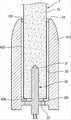
図1ないし図3に示された実施形態に係わるエアロゾル生成装置は、シガレット7を収容することができるケース10と、一側端部31がケース10の内部に挿入され、シガレット7を加熱するヒータ30と、を具備する。 The aerosol generator according to the embodiment shown in FIGS. 1 to 3 has a
ケース10は、エアロゾル生成装置の外観を形成し、内部に形成された空間にさまざまな構成要素を収容して保護する機能を遂行する。ケース10は、全体的に内部が空いている中空の円筒形状を有し、前方端部が外部に開放され、シガレット7が挿入される。 The
ケース10は、電気及び熱を伝達させないプラスチック素材や、表面にプラスチック素材がコーティングされた金属性素材によっても作製される。図示された実施形態において、ケース10が円形の断面を有する円筒形状を有するものの、本実施形態は、そのようなケース10の構成によって限定されるものではない。例えば、ケース10は、四角形のような多角形の断面を有する筒形状を有することができる。 The
図2を参照すれば、ケース10は、シガレット7を収容するための通路20を具備する中空状の内筒11と、内筒11の外側に結合される中空状の中間筒12と、中間筒12の外側に結合される外筒13と、を具備する。 Referring to FIG. 2, the
内筒11は、シガレット7を収容するための通路20と、外部からシガレット7が挿入されるように、通路20の一端20fにおいて外部に開放された開口21と、通路20の他端20rに連結された通孔22と、を具備する。内筒11は、通路20の内壁面から通路20の中心に向けて突出し、シガレット7の外側面7sの一部分に接触する突起25を具備する。 The
内筒11は、ケース10の最も内側に配置され、外部から挿入されるシガレット7が通路20に沿って移動するように、シガレット7の移動経路を提供し、シガレット7を収容する機能を遂行する。内筒11と中間筒12と外筒13とが結合された後、エアロゾル生成装置が使用される間、内筒11は、中間筒12と外筒13とに対し、相対的に移動せずに、位置が固定された状態を維持する。 The
内筒11に形成された通路20は、シガレット7の形状に対応する円筒形状に形成される。本実施形態は、通路20の形状によって制限されるものではなく、例えば、通路20の形状が、四角形のような多角形の断面を有する筒形状にも形成される。 The
通路20の直径は、シガレット7の内径より大きく形成されるので、通路20にシガレット7が収容されれば、通路20とシガレット7とに空間が形成される。従って、通路20とシガレット7との間には、通路20の開口21を介して外部に連結され、空気が通過することができる流路25pが形成される。 Since the diameter of the
ケース10は、通路20の他端20rを覆う底壁29を具備する。図1ないし図3に図示された実施形態において、底壁29は、内筒11の外側に結合された中間筒12によって形成される。底壁29は、通路20に収容されるシガレット7の端部7eの底面7dと接触する。また、底壁29は、通路20と連結される通孔22を有する。 The
エアロゾル生成装置のユーザが、シガレット7を通路20に挿入し、シガレット7が通路20に沿って移動していて、シガレット7の端部7eが底壁29に逹すれば、シガレット7を手にしているユーザの手に、底壁29とシガレット7の端部7eとが接触する感じが伝達される。従って、ユーザは、シガレット7を手にし、通路20の開口21にシガレット7を押し込む簡単な動作を実施することにより、シガレット7をエアロゾル生成装置に簡便に装着することができる。 If the user of the aerosol generator inserts the
ケース10には、シガレット7を加熱する機能を遂行するヒータ30が結合される。ヒータ30の一側端部31は、底壁29の通孔22を介して、通路20の内部に配置され、ケース10にシガレット7が収容される場合、ヒータ30の一側端部31がシガレット7の端部7eの底面7dに挿入される。 A
底壁29に形成された通孔22の大きさは、ヒータ30の一側端部31の厚みに対応する。例えば、ヒータ30の一側端部31が円形の断面を有する場合、通孔22も、円形の断面形状を有し、通孔22の内径は、ヒータ30の一側端部31の外径に対応するように形成される。 The size of the through
本実施形態は、通孔22の内径の大きさによって制限されるものではなく、例えば、通孔22の内径は、ヒータ30の一側端部31の外径より大きく形成され、通孔22の内面がヒータ30の一側端部31の外側面からも離隔される。 The present embodiment is not limited by the size of the inner diameter of the through
ヒータ30の他側端部32は、電気配線71を介して、ケース10の後方に配置された電気供給装置72に電気的に連結される。ケース10の後方には、電気供給装置72を取り囲むベース19が連結される。ヒータ30の一側端部31にシガレット7が挿入された状態で、電気供給装置72の電気がヒータ30に供給されれ、ばヒータ30が加熱されることにより、シガレット7が加熱される。 The
図3を参照すれば、内筒11には、複数個の突起25が配置される。突起25は、シガレット7の外側面7sにおいて、シガレット7の中心に対する周囲方向に沿って互いに離隔されるように配置されることにより、隣接した突起25間に空気が通過することができる流路25pが形成される。 Referring to FIG. 3, a plurality of
図1ないし図3に図示された実施形態において、シガレット7は、円筒形状を有し、内筒11の通路20も、シガレット7の形状に対応する円筒形状を有する。従って、突起25は、シガレット7の外側面7sにおいて、シガレット7の中心に対する円周方向に沿って互いに離隔されるように配置される。また、図面に図示された突起25の個数が4個であるものの、本実施形態は、そのような突起25の個数によって限定されないので、突起25の個数を多様に変形することができる。また、突起25の設置位置も、多様に変形される。 In the embodiment illustrated in FIGS. 1 to 3, the
シガレット7の外側面7sと接触する突起25の端部面は、シガレット7の外側面7sの形状に対応するように、湾曲された円筒面にも形成される。 The end surface of the
図1及び図2を参照すれば、突起25は、通路20の開口21と通孔22とのおよそ中間地点の位置に形成される。従って、通路20は、開口21を介して、外部と連結され、外部の空気が、開口21を介してケース10の通路20に流入される。 With reference to FIGS. 1 and 2, the
シガレット7の端部7eの外側面7rには、いかなる構成要素も接触しないので、シガレット7の端部7eの外側面7rは、空気によって取り囲まれた状態に置かれる。ヒータ30がシガレット7を加熱し、シガレット7からエアロゾル粒子が発生するとき、ユーザがシガレット7を口にして空気を吸い込めば、シガレット7の端部7eの外側面7rの空気がシガレット7を通過することにより、エアロゾル粒子を含む空気の流れがユーザにも伝達される。 Since no component comes into contact with the
図1ないし図3に示された実施形態に係わるエアロゾル生成装置においては、ユーザがシガレット7をケース10の通路20に挿入した後、通路20に沿ってシガレット7を押し込む簡便な操作により、エアロゾル生成装置にシガレット7を容易に装着することができる。また、シガレット7の使用を終えた後には、ユーザがシガレット7の上側端部を手で取り、通路20の外側nにシガレット7を引っ張る簡便な操作により、エアロゾル生成装置からシガレット7を分離させることができる。 In the aerosol generator according to the embodiment shown in FIGS. 1 to 3, the user inserts the
また、エアロゾル生成装置のケース10の通路20にシガレット7が挿入された状態では、通路20の突起25がシガレット7の外側面7sに接触することにより、突起25がシガレット7を安定して支持する。従って、該エアロゾル生成装置を使用している最中、シガレット7がエアロゾル生成装置から分離せず、エアロゾル生成装置の通路20にシガレット7が収容された状態が安定して維持されるので、ユーザは、安全にエアロゾル生成装置を満喫することができる。 Further, when the
また、ケース10の通路20の突起25が、シガレット7の外側面7sの一部分と接触することにより、通路20とシガレット7との間に空気が通過することができる流路25pが形成されるので、エアロゾル発生を補助するための外部空気が、エアロゾル生成装置の内部に十分に円滑に供給される。 Further, when the
図4は、他の実施形態に係わるエアロゾル生成装置の断面図であり、図5は、図4に示された実施形態に係わるエアロゾル生成装置のV-Vの線に沿って切り取った断面図であり、図6、は図4に示された実施形態に係わるエアロゾル生成装置の一部分を拡大して図示した拡大断面図である。 FIG. 4 is a cross-sectional view of the aerosol generator according to another embodiment, and FIG. 5 is a cross-sectional view taken along the VV line of the aerosol generator according to the embodiment shown in FIG. FIG. 6 is an enlarged cross-sectional view showing a part of the aerosol generator according to the embodiment shown in FIG. 4 in an enlarged manner.
図4ないし図6に示された実施形態に係わるエアロゾル生成装置においては、突起125の位置が、図1ないし図3に図示された実施形態の突起25の位置と異なるように変形された。 In the aerosol generator according to the embodiment shown in FIGS. 4 to 6, the position of the
突起125は、通路20の他端20rから通路20の中心に向けて内側に突出するように形成される。図6を参照すれば、シガレット7が、ケース10の内筒11の通路20に収容されたとき、突起125が、通路20の他端20rに位置するシガレット7の端部7eの外側面7rの一部分に接触する。 The
図5を参照すれば、突起125は、シガレット7の外側面7sにおいて、シガレット7の中心に対して円周方向に互いに離隔されるように複数個が配置される。そのような突起125の配置構造により、突起125間に空気が通過する流路が形成される。 Referring to FIG. 5, a plurality of
図6を参照すれば、突起125は、シガレット7の端部7eの外側面7rに接触する接触面125dと、通路20の一端20fから他端20rに向かう方向に、通路20の中心に向けて傾斜をなす傾斜面125tと、を具備する。 Referring to FIG. 6, the
突起125の傾斜面125tは、シガレット7が通路20に挿入され、通路20に沿って移動し、シガレット7の端部7eが通路20の他端20rに達すれば、シガレット7の端部7eが突起125に挿入されるように、シガレット7の動きを案内する機能を遂行する。 The
図4ないし図6に示された実施形態に係わるエアロゾル生成装置においては、通路20の一端20fから他端20rに至るシガレット7の外側面7sのほとんどに、他の構成要素が接触しないが、シガレット7の端部7eが、通路20の他端20rに突出する突起125と、シガレット7に挿入されたヒータ30とによって安定して支持される。 In the aerosol generator according to the embodiment shown in FIGS. 4 to 6, most of the
また、ユーザが、シガレット7をケース10の通路20に挿入した後、通路20に沿ってシガレット7を突起125の位置まで押し込む簡便な操作により、エアロゾル生成装置にシガレット7を容易に装着することができ、また、シガレット7の使用を終えた後には、ユーザが、シガレット7の上側端部を手に取り、通路20の外側にシガレット7を引っ張る簡便な操作により、エアロゾル生成装置からシガレット7を容易に分離させることができる。 Further, the user can easily attach the
また、ケース10の通路20の突起125が、シガレット7の端部7eの外側面7rの一部分と接触することにより、通路20とシガレット7との間に空気が通過することができる流路が形成されるので、エアロゾル発生を補助するための外部の空気が、エアロゾル生成装置の内部に十分に円滑に供給される。 Further, when the
図7は、さらに他の実施形態に係わるエアロゾル生成装置の断面図である。 FIG. 7 is a cross-sectional view of an aerosol generator according to still another embodiment.
図7に示された実施形態に係わるエアロゾル生成装置は、シガレット7を収容することができる通路20と、通路20において突出した突起225を具備したケース210と、一側端部31がケース210の内部に挿入され、シガレット7を加熱するヒータ30と、を具備する。 The aerosol generator according to the embodiment shown in FIG. 7 has a
図7に示された実施形態に係わるエアロゾル生成装置においては、ケース210の構造が、図1ないし図6に示された実施形態のケースの構造から変形されている。 In the aerosol generator according to the embodiment shown in FIG. 7, the structure of the
ケース210は、中空の円筒形状に作製され、シガレット7を収容するための通路20と、外部からシガレット7が挿入されるように、通路20の一端20fにおいて外部に開放された開口21と、通路20の他端20rに連結された通孔22と、通路20の内壁面から通路20の中心に向けて突出し、シガレット7の外側面7sの一部分に接触する突起225と、を具備する。 The
通路20の直径は、シガレット7の外径より大きく形成されるので、通路20にシガレット7が収容されれば、通路20とシガレット7とに空間が形成される。従って、通路20とシガレット7との間には、通路20の開口21を介して外部に連結され、空気が通過することができる流路25pが形成される。 Since the diameter of the
ケース210は、通路20の他端20rを覆う底壁29を具備する。底壁29は、通路20に収容されるシガレット7の端部7eの底面7dと接触する。また、底壁29には、通路20と連結されるように、通孔22が貫通して形成される。 The
底壁29は、シガレット7の外側面7sと、通路20の内壁面との間に形成される空間(流路25p)と連結される連結通路29pを具備する。連結通路29pは、通路20の開口21を介して、外部から通路20に流入された空気を、シガレット7の端部7eの底面7dに供給する機能を遂行する。連結通路29pは、底壁29において、通孔22を中心に円周方向に延長する凹形状の溝によって形成されるか、あるいは通孔22の外側に凹形状に形成される複数個の溝によっても形成される。 The
ケース210には、シガレット7を加熱する機能を遂行するヒータ30が結合される。ヒータ30の一側端部31は、底壁29の通孔22を介して通路20の内部に配置され、ケース210にシガレット7が収容される場合、ヒータ30の一側端部31がシガレット7の端部7eの底面7dに挿入される。 A
ヒータ30の他側端部32は、電気配線71を介して、ケース210の後方に配置された電気供給装置72に電気的に連結される。ケース210の後方には、電気供給装置72を取り囲むベース19が連結される。ヒータ30の一側端部31にシガレット7が挿入された状態で、電気供給装置72の電気がヒータ30に供給されれば、ヒータ30が加熱されることにより、シガレット7が加熱される。 The
ケース210の通路20には、複数個の突起225が配置される。突起225は、シガレット7の外側面7sにおいて、シガレット7の中心に対する円周方向に沿って互いに離隔されるように配置される。複数個の突起225がシガレット7の中心に対する円周方向に沿って互いに離隔されるように配置される構造は、図1ないし図6に示された実施形態に係わる突起の配置構造と同一である。また、図7において、複数個の突起225は、シガレット7の外側面7sにおいて、シガレット7の長手方向に沿って互いに離隔されるように配置される。突起225は、およそ半球形状を有する。 A plurality of
そのように、複数個の突起225の一部は、シガレット7の外側面7sにおいて、シガレット7の中心に対する円周方向に沿って互いに離隔されるように配置され、複数個の突起225の他の一部は、シガレット7の外側面7sにおいて、シガレット7の長手方向に沿って互いに離隔されるように配置されるので、隣接した突起225間に空気が通過する流路25pが形成される。 As such, some of the plurality of
図7に示された実施形態に係わるエアロゾル生成装置においては、また、ケース210の通路20の突起225がシガレット7の外側面7sの一部分と接触することにより、通路20とシガレット7との間に空気が通過することができる流路25pが形成され、流路25pの空気が、底壁29の連結通路29pを介して、シガレット7の端部7eの底面7dに供給されるので、エアロゾル発生を補助するための十分な空気がシガレット7に円滑に供給される。 In the aerosol generator according to the embodiment shown in FIG. 7, the
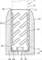
図8は、さらに他の実施形態に係わるエアロゾル生成装置の断面図であり、図9は、図8に示された実施形態に係わるエアロゾル生成装置の構成要素の結合関係を概略的に図示した斜視図である。 FIG. 8 is a cross-sectional view of the aerosol generator according to still another embodiment, and FIG. 9 is a perspective view schematically showing the coupling relationship of the components of the aerosol generator according to the embodiment shown in FIG. It is a figure.
図8及び図9に示された実施形態に係わるエアロゾル生成装置は、シガレット7を収容することができる通路20、通路20において突出した突起225を具備したケース210と、一側端部31が、ケース210の内部に挿入され、シガレット7を加熱するヒータ30と、を具備する。 The aerosol generator according to the embodiment shown in FIGS. 8 and 9 has a
ケース210は、通路20の他端20rを覆う底壁29を具備する。底壁29は、通路20に収容されるシガレット7の端部の底面7dと接触する。また、底壁29には、通路20と連結される通孔22が、底壁29を貫通するように形成される。 The
ケース210の通路20の他端20rを覆う底壁29は、底突起226を具備する。底突起226は、底壁29から通路20の内部空間に向けて突出することにより、シガレット7の端部の底面7dを支持する機能を遂行する。底突起226は、およそ半球状を有する。 The
底突起226は、底壁29において、底壁29に形成された通孔22の中心に対する円周方向に沿って互いに離隔されるように複数個が配置される。従って、隣接した底突起226間の空間を介して空気が通過することができるので、通路20の開口21を介して、外部から通路20に流入された空気は、底突起226間の空間を介して、シガレット7の端部の底面7dに供給される。 A plurality of
ケース210には、シガレット7を加熱する機能を遂行するヒータ30が結合される。ヒータ30の一側端部31は、底壁29の通孔22を介して通路20の内部に配置され、ケース210にシガレット7が収容される場合、ヒータ30の一側端部31が、シガレット7の端部7eの底面7dに挿入される。 A
ヒータ30の他側端部32は、電気配線71を介して、ケース210の後方に配置された電気供給装置72に電気的に連結される。ケース210の後方には、電気供給装置72を取り囲むベース19が連結される。ヒータ30の一側端部31にシガレット7が挿入された状態で、電気供給装置72の電気がヒータ30に供給されれば、ヒータ30が加熱されることにより、シガレット7が加熱される。 The
ケース210の通路20には、複数個の突起225が配置される。突起225は、シガレット7の外側面7sにおいて、シガレット7の中心に対する円周方向に沿って互いに離隔されるように配置される。複数個の突起225がシガレット7の中心に対する円周方向に沿って互いに離隔されるように配置される構造は、図1ないし図6に示された実施形態に係わる突起の配置構造と同一である。また、図8及び図9において、複数個の突起225は、シガレット7の外側面7sにおいて、シガレット7の長手方向に沿って互いに離隔されるように配置される。 A plurality of
図8及び図9に示された実施形態に係わるエアロゾル生成装置においては、また、ケース210の通路20の突起225が、シガレット7の外側面7sの一部分と接触することにより、通路20とシガレット7との間に空気が通過することができる流路25pが形成され、流路25pの空気が、底壁29の底突起226間の空間を介して、シガレット7の端部の底面7dに供給されるので、エアロゾル発生を補助するための十分な空気がシガレット7に円滑に供給される。 In the aerosol generator according to the embodiment shown in FIGS. 8 and 9, the
図10は、さらに他の実施形態に係わるエアロゾル生成装置の断面図であり、図11は、図10に示された実施形態に係わるエアロゾル生成装置の一部分を概略的に図示した斜視図である。 FIG. 10 is a cross-sectional view of the aerosol generator according to still another embodiment, and FIG. 11 is a perspective view schematically showing a part of the aerosol generator according to the embodiment shown in FIG.
図10及び図11に示された実施形態に係わるエアロゾル生成装置は、シガレット7を収容することができる通路20、通路20において突出した突起325を具備したケース310と、一側端部31がケース310の内部に挿入され、シガレット7を加熱するヒータ30と、を具備する。 The aerosol generator according to the embodiment shown in FIGS. 10 and 11 includes a
ケース310は、通路20の他端20rを覆う底壁29を具備する。底壁29は、通路20に収容されるシガレット7の端部の底面7dと接触する。また、底壁29には、通路20と連結される通孔22が底壁29を貫通するように形成される。 The
ケース310の通路20の他端20rを覆う底壁29は、底突起326を具備する。底突起326は、底壁29から通路20の内部空間に向けて突出し、通孔22の中心に向かう放射方向に延長することにより、シガレット7の端部の底面7dを支持する機能を遂行する。底突起326は、およそ直方体状を有する。 The
底突起326は、底壁29において、底壁29に形成された通孔22の中心に対する円周方向に沿って互いに離隔されるように複数個が配置される。従って、隣接した底突起326間の空間を介して、空気が通過することができるので、通路20の開口21を介して、外部から通路20に流入された空気は、底突起326間の空間を介して、シガレット7の端部の底面7dに供給される。 A plurality of
ケース310の通路20には、複数個の突起325が配置される。突起325は、シガレット7の外側面7sにおいて、シガレット7の中心に対する円周方向に沿って互いに離隔されるように配置される。複数個の突起325がシガレット7の中心に対する円周方向に沿って互いに離隔されるように配置される構造は、図1ないし図6に示された実施形態に係わる突起の配置構造と同一である。また、図10及び図11において、複数個の突起325は、シガレット7の長手方向に沿って延長すると共に、シガレット7の外側面7sにおいて、シガレット7の長手方向に沿って互いに離隔されるように配置される。 A plurality of
図10及び図11に示された実施形態に係わるエアロゾル生成装置においては、互いに離隔されるように配置された複数個の突起325間の空間を介して、外部の空気がケース310の通孔22に円滑に導入される。また、突起325がシガレット7の長手方向に延長されるので、突起325が通孔22に沿って挿入されるシガレット7の動きを円滑に案内することができる。また、シガレット7の外側面7sの一部分に接する突起325の表面は、シガレット7の外側面7sに対応するように、湾曲された円筒面に形成されるので、突起325が通孔22に収容されたシガレット7を安定して支持することができる。 In the aerosol generator according to the embodiment shown in FIGS. 10 and 11, external air passes through a
図12は、さらに他の実施形態に係わるエアロゾル生成装置の一部構成要素の結合関係を概略的に図示した斜視図であり、図13は、図12に示された実施形態に係わるエアロゾル生成装置の断面図である。 FIG. 12 is a perspective view schematically showing the coupling relationship of some components of the aerosol generating apparatus according to still another embodiment, and FIG. 13 is a perspective view schematically showing the coupling relationship of the partial components of the aerosol generating apparatus according to the other embodiment, and FIG. 13 is an aerosol generating apparatus according to the embodiment shown in FIG. It is a cross-sectional view of.
図12及び図13に示された実施形態に係わるエアロゾル生成装置は、シガレット7を収容することができる通路20、通路20において突出した突起425を具備したケース410と、一側端部31がケース410の内部に挿入され、シガレット7を加熱するヒータ30と、を具備する。 The aerosol generator according to the embodiment shown in FIGS. 12 and 13 includes a
ケース410の通路20には、複数個の突起425が配置される。突起425は、シガレット7の外側面7sにおいて、シガレット7の中心に対する円周方向に沿って互いに離隔されるように配置されることにより、隣接した突起425の間に空気の通過する流路が形成される。 A plurality of
また、複数個の突起425は、シガレット7の長手方向に沿って、すなわち、通路20の延長方向に沿って、通路20の一端20fから通路20の他端20rに至るまで直線的に延長する。 Further, the plurality of
図12及び図13において、複数個の突起425は、通路20の横方向の断面を垂直するように横切り、直線的に延長するものの、本実施形態は、そのような突起425の構造によって制限されるものではない。例えば、突起425は、通路20の断面に対して傾斜をなすように直線的に延長するか、あるいは曲線的に延長することもできる。 In FIGS. 12 and 13, the plurality of
また、突起425のそれぞれは、通路20に収容されたシガレット7の端部の底面7dに接触するように、通路20の中心に向けて曲折されて突出する底突出部426を具備する。通路20の他端20rにおいては、複数個の突起425のそれぞれの底突出部426の内側面に沿って通路20に連結される通孔22が形成される。 Further, each of the
ヒータ30の一側端部31は、底突出部426によって形成される通孔22を介して、通路20の内部に配置され、ケース410にシガレット7が収容される場合、ヒータ30の一側端部31がシガレット7の端部7eの底面7dに挿入される。 One
図12及び図13に示された実施形態に係わるエアロゾル生成装置においては、互いに離隔されるように配置された複数個の突起425間の空間を介して、外部の空気がケース410の通孔22にも円滑に導入される。また、突起425がシガレット7の長手方向に延長されるので、突起425が通孔22に沿って挿入されるシガレット7の動きを円滑に案内することができる。また、シガレット7の外側面7sの一部分に接する突起425の表面は、シガレット7の外側面7sに対応するように、湾曲された円筒面に形成されるので、突起425が、通孔22に収容されたシガレット7を安定して支持することができる。また、突起425の底突出部426が、通孔22に収容されたシガレット7の端部の底面7dを安定して支持することができる。 In the aerosol generator according to the embodiment shown in FIGS. 12 and 13, external air passes through the
図14は、さらに他の実施形態に係わるエアロゾル生成装置の断面図である。 FIG. 14 is a cross-sectional view of an aerosol generator according to still another embodiment.
図14に示された実施形態に係わるエアロゾル生成装置は、シガレット7を収容することができる通路20、通路20において突出した突起525を具備したケース510と、一側端部31がケース510の内部に挿入され、シガレット7を加熱するヒータ30と、を具備する。 The aerosol generator according to the embodiment shown in FIG. 14 includes a
ケース510は、通路20の他端20rを覆う底壁29を具備する。底壁29は、通路20に収容されるシガレット7の端部7eの底面7dと接触する。また、底壁29には、通路20と連結される通孔22が底壁29を貫通するように形成される。 The
ケース510の通路20の他端20rを覆う底壁29は、底突起526を具備する。底突起526は、底壁29から通路20の内部空間に向けて突出することにより、シガレット7の端部の底面7dを支持する機能を遂行する。底突起526は、およそ半球形状を有する。 The
底突起526は、底壁29において、底壁29に形成された通孔22の中心に対する円周方向に沿って、互いに離隔されるように、複数個が配置される。従って、隣接した底突起526間の空間を介して、空気が通過することができるので、通路20の開口21を介して、外部から通路20に流入された空気は、底突起526間の空間を介して、シガレット7の端部の底面7dに供給される。 A plurality of
ケース510の通路20には、複数個の突起525が配置される。突起525は、シガレット7の外側面7sにおいて、シガレット7の中心に対する円周方向に沿って、互いに離隔されるように配置される。突起525は、およそ半球形状を有する。 A plurality of
ケース510は、通路20の他端20rにおいて突出する端部突起528を具備する。端部突起528は、シガレット7が通路20に収容されたとき、通路20の他端20rに位置するシガレット7の端部7eの外側面7rの一部分に接触するように、通路20において突出する。端部突起528は、およそ半球形状を有する。 The
図14に示された実施形態に係わるエアロゾル生成装置においては、通路20の一端20fと他端20rとの間のおよそ中間地点において、シガレット7の外側面7sの一部分を支持する突起525と、通路20の他端20rにおいて、シガレット7の端部7eの外側面7rの一部分を支持する端部突起528と、通路20の底壁29から突出し、シガレット7の端部7eの底面7dを支持する底突起526と、により、シガレット7が通路20の内部に安定して支持される。 In the aerosol generator according to the embodiment shown in FIG. 14, a
また、互いに離隔されるように配置された複数個の突起525間の空間を介して、外部の空気がケース510の通孔22に円滑に導入された後、通路20の他端20rの端部突起528間の空間と、底突起526間の空間とを介して、シガレット7の端部7eの底面7dに円滑に供給される。 Further, after the external air is smoothly introduced into the through
図15は、さらに他の実施形態に係わるエアロゾル生成装置の一部構成要素を概略的に図示した断面図である。 FIG. 15 is a cross-sectional view schematically showing a part of the components of the aerosol generator according to still another embodiment.
図15に示された実施形態に係わるエアロゾル生成装置のケース610は、シガレット7を収容することができる通路20と、通路20において突出した突起625と、を具備する。 The
ケース610は、通路20の他端20rを覆う底壁29を具備する。底壁29は、通路20に収容されるシガレット7の端部7eの底面7dと接触する。また、底壁29には、通路20と連結される通孔22が底壁29を貫通するように形成される。 The
ケース610の通路20の他端20rを覆う底壁29は、底突起626を具備する。底突起626は、底壁29から通路20の内部空間に向けて突出することにより、シガレット7の端部の底面7dを支持する機能を遂行する。底突起626は、およそ半球形状を有する。 The
底突起626は、底壁29に形成された通孔22の中心に対する円周方向に沿って、互いに離隔されるように、底壁29の表面に複数個が配置される。従って、隣接した底突起626間の空間を介して、空気が通過することができるので、通路20の開口21を介して、外部から通路20に流入された空気は、底突起626間の空間を介して、シガレット7の端部の底面7dに供給される。 A plurality of
ケース610の通路20には、複数個の突起625が配置される。突起625は、シガレット7の外側面7sにおいて、シガレット7の中心に対する円周方向に沿って、互いに離隔されるように配置される。また、複数個の突起625は、シガレット7の外側面7sにおいて、シガレット7の長手方向に沿って、互いに離隔されるように配置される。 A plurality of
また、複数個の突起625のそれぞれのシガレット7の長手方向での断面形状は、シガレット7の長手方向に沿って長く延長する楕円形または流線形にも形成される。突起625の断面形状が、楕円形または流線形に形成されることにより、隣接した突起625間の空間を通過する空気の流れがさらに円滑に形成される。 Further, the cross-sectional shape of each of the plurality of
ケース610は、通路20の他端20rにおいて突出する端部突起628を具備する。端部突起628は、シガレット7が通路20に収容されたとき、通路20の他端20rに位置するシガレット7の端部7eの外側面7rの一部分に接触するように、通路20において突出する。端部突起628のシガレット7の長手方向での断面形状は、シガレット7の長手方向に沿って長く延長する楕円形または流線形にも形成される。 The
図15に示された実施形態に係わるエアロゾル生成装置においては、通路20の一端20fと他端20rとの間において、シガレット7の外側面7sの一部分を支持する複数個の突起625と、通路20の他端20rにおいて、シガレット7の端部7eの外側面7rの一部分を支持する端部突起628と、通路20の底壁29から突出し、シガレット7の端部7eの底面7dを支持する底突起626とにより、通路20の内部において、シガレット7が安定して支持される。 In the aerosol generator according to the embodiment shown in FIG. 15, a plurality of
図16は、さらに他の実施形態に係わるエアロゾル生成装置の一部構成要素を概略的に図示した断面図であり、図17は、図16に示された実施形態に係わるエアロゾル生成装置の斜視図である。 FIG. 16 is a cross-sectional view schematically showing a part of the components of the aerosol generator according to still another embodiment, and FIG. 17 is a perspective view of the aerosol generator according to the embodiment shown in FIG. Is.
図16及び図17に示された実施形態に係わるエアロゾル生成装置のケース710は、シガレット7を収容することができる通路20と、通路20において突出した突起725と、を具備する。 The
ケース710は、通路20の他端20rを覆う底壁29を具備する。底壁29は、通路20に収容されるシガレット7の端部7eの底面7dと接触する。また、底壁29には、通路20と連結される通孔22が底壁29を貫通するように形成される。 The
ケース710の通路20の他端20rを覆う底壁29は、底突起726を具備する。底突起726は、底壁29から通路20の内部空間に向けて突出することにより、シガレット7の端部の底面7dを支持する機能を遂行する。 The
底突起726は、底壁29に形成された通孔22の中心に対する円周方向に沿って、互いに離隔されるように、底壁29の表面の上に複数個が配置される。従って、隣接した底突起726間の空間を介して、空気が通過することができるので、通路20の開口21を介して、外部から通路20に流入された空気は、底突起726間の空間を介して、シガレット7の端部の底面7dに供給される。 A plurality of
ケース710の通路20には、複数個の突起725が配置される。突起725は、シガレット7の外側面7sにおいて、シガレット7の中心に対する円周方向に沿って、互いに離隔されるように配置される。また、複数個の突起725は、シガレット7の外側面7sにおいて、シガレット7の長手方向に沿って、互いに離隔されるように配置される。 A plurality of
また、複数個の突起725のそれぞれは、シガレット7の長手方向に対して傾斜をなすように傾き、シガレット7の中心に対して円周方向に延長する。本実施形態は、複数個の突起725のそれぞれが延長する方向によって制限されるものではなく、例えば、複数個の突起725のそれぞれは、シガレット7の長手方向に対して傾斜をなさず、シガレット7の中心に対して円周方向だけに水平に延長することもできる。 Further, each of the plurality of
ケース710は、通路20の他端20rにおいて突出する端部突起728を具備する。端部突起728は、シガレット7が通路20に収容されたとき、通路20の他端20rに位置するシガレット7の端部7eの外側面7rの一部分に接触するように、通路20において突出する。また、端部突起728と底突起726は、通路20の他端20rのコーナーで互いに連結される。 The
図16及び図17に示された実施形態に係わるエアロゾル生成装置においては、通路20の一端20fと、他端20rとの間において、シガレット7の外側面7sの一部分を支持する複数個の突起725と、通路20の他端20rにおいて、シガレット7の端部7eの外側面7rの一部分を支持する端部突起728と、通路20の底壁29から突出し、シガレット7の端部7eの底面7dを支持する底突起726とにより、通路20の内部において、シガレット7が安定して支持される。 In the aerosol generator according to the embodiment shown in FIGS. 16 and 17, a plurality of
以下の図18ないし図30A〜図30Fに図示された実施形態は、前述の図1ないし図17に図示された実施形態に係わるエアロゾル生成装置に適用される変形されたエアロゾル生成装置と、エアロゾル生成方法とを図示する。 The embodiments shown in FIGS. 18 to 30A to 30F below include a modified aerosol generator applied to the aerosol generator according to the embodiment shown in FIGS. 1 to 17 described above, and an aerosol generation apparatus. The method is illustrated.
図18ないし図30A〜図30Fで構成要素を示す番号は、図1ないし図17で使用された番号と関連性なしに独立して使用されている。従って、図1ないし図17において、構成要素を示した番号と、図18ないし図30A〜図30Fで構成要素を示す番号は、互いに独立して異なる構成要素を示すために使用されたものであると理解されなければならない。 The numbers indicating the components in FIGS. 18 to 30A to 30F are used independently of the numbers used in FIGS. 1 to 17. Therefore, in FIGS. 1 to 17, the numbers indicating the components and the numbers indicating the components in FIGS. 18 to 30A to 30F are used to indicate different components independently of each other. Must be understood.
図18は、エアロゾル生成装置の一例を図示した構成図である。 FIG. 18 is a configuration diagram illustrating an example of an aerosol generator.
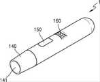
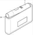
図18を参照すれば、エアロゾル生成装置1(以下、ホルダとする)は、バッテリ110、制御部120及びヒータ130を含む。また、ホルダ1は、ケース140によって形成された内部空間を含む。ホルダ1の内部空間には、シガレットが挿入される。 Referring to FIG. 18, the aerosol generator 1 (hereinafter referred to as a holder) includes a
図18に図示されたホルダ1には、本実施形態と係わる構成要素だけが図示されている。従って、図18に図示された構成要素以外に、他の汎用的な構成要素がホルダ1にさらに含まれてもよいということは、本実施形態と係わる技術分野において当業者であるならば、理解することができるであろう。 In the
シガレットがホルダ1に挿入されれば、ホルダ1は、ヒータ130を加熱する。シガレット内のエアロゾル生成物質は、加熱されたヒータ130によって温度が上昇し、それにより、エアロゾルが生成される。生成されたエアロゾルは、シガレットのフィルタを介してユーザに伝達される。ただし、該シガレットがホルダ1に挿入されていない場合にも、ホルダ1は、ヒータ130を加熱することができる。 If the cigarette is inserted into the
ケース140は、ホルダ1から分離される。例えば、ユーザが、ケース140を、時計回り方向または反時計回り方向に回すことにより、ケース140は、ホルダ1から分離される。 The
また、ケース140の末端141が形成する孔の直径は、ケース140とヒータ130とによって形成された空間の直径に比べ、小さく作製され、その場合、ホルダ1に挿入されるシガレットのガイド役割を行うことができる。 Further, the diameter of the hole formed by the
バッテリ110は、ホルダ1が動作するのに利用される電力を供給する。例えば、バッテリ110は、ヒータ130が加熱されるように電力を供給することができ、制御部120が動作するのに必要な電力を供給することができる。また、バッテリ110は、ホルダ1に設けられたディスプレイ、センサ、モータなどが動作するのに必要な電力を供給することができる。 The
バッテリ110は、リチウムリン酸鉄(LiFePO4)バッテリでもあるが、前述の例に限定されるものではない。例えば、バッテリ110は、酸化リチウムコバルト(LiCoO2)バッテリ、リチウムチタン酸塩バッテリなどが該当する。The
また、バッテリ110は、直径が10mmであり、長さが37mmである円柱状でもあるが、それに限定されるものではない。バッテリ110の容量は、120mAh以上でもあり、充電が可能なバッテリであるか、あるいは1回使用バッテリでもある。例えば、バッテリ110が充電が可能である場合、バッテリ110の充電率(C−rate)は、10C、放電率(C−rate)は、16Cないし20Cでもあるが、それらに限定されるものではない。また、安定した使用のために、バッテリ110は、充放電が8,000回進められた場合にも、全体容量の80%以上が確保されるように作製される。 Further, the
ここで、バッテリ110の満充電及び完全放電のいかんは、バッテリ110に保存された電力が、バッテリ110の全体容量対比で、どれほとのレベルであるかということによっても判断される。例えば、バッテリ110に保存された電力が、全体容量の95%以上である場合、バッテリ110が満充電されたと判断される。また、バッテリ110に保存された電力が、全体容量の10%以下である場合、バッテリ110が完全放電されたと判断される。しかし、バッテリ110の満充電及び完全放電のいかんに係わる判断基準は、前述の例に限定されるものではない。 Here, whether the
ヒータ130は、バッテリ110から供給された電力によって加熱される。シガレットがホルダ1に挿入されれば、ヒータ130は、該シガレットの内部に位置する。従って、加熱されたヒータ130は、シガレット内のエアロゾル生成物質の温度を上昇させる。 The
ヒータ130は、円柱と円錐とが組み合わされた形状でもある。例えば、ヒータ130は、直径が約2mm、長さが約23mmである円柱状を有し、ヒータ130の末端2131は、鋭角に仕上げられるが、それに限定されるものではない。言い換えれば、ヒータ130は、シガレットの内部に挿入される形態であるならば、制限なしに該当する。また、ヒータ130は、一部分だけ加熱されもする。例えば、ヒータ130の長さが23mmであると仮定すれば、ヒータ130の末端131から12mmだけ加熱され、ヒータ130の残り部分は、加熱されない。 The
ヒータ130は、電気抵抗性ヒータでもある。例えば、ヒータ130には、電気伝導性トラック(track)を含み、該電気伝導性トラックに電流が流れることにより、ヒータ130が加熱される。 The
安定した使用のために、ヒータ130には、3.2V、2.4A、8Wの規格による電力が供給されるが、それらに限定されるものではない。例えば、ヒータ130に電力が供給される場合、ヒータ130の表面温度は、400℃以上に上昇する。ヒータ130に電力が供給され始めたときから15秒が超える前、ヒータ130の表面温度は、約350℃まで上昇する。 For stable use, the
ホルダ1には、別途の温度感知センサが具備される。または、ホルダ1に温度感知センサが具備されず、ヒータ130が、温度感知センサの役割を行うこともできる。例えば、ヒータ130には、発熱のための第1電気伝導性トラック以外に、温度感知のための第2電気伝導性トラックがさらに含まれてもよい。 The
例えば、該第2電気伝導性トラックにかかる電圧、及び第2電気伝導性トラックに流れる電流が測定されれば、抵抗(R)が決定される。このとき、下記数式1により、第2電気伝導性トラックの温度(T)が決定される。 For example, the resistance (R) is determined by measuring the voltage applied to the second electrically conductive track and the current flowing through the second electrically conductive track. At this time, the temperature (T) of the second electrically conductive track is determined by the following

数式1で、Rは、第2電気伝導性トラックの現在抵抗値を意味し、R0は、温度T0(例えば、0℃)での抵抗値を意味し、αは、第2電気伝導性トラックの抵抗温度係数を意味する。伝導性物質(例えば、金属)は、固有の抵抗温度係数を有しているが、第2電気伝導性トラックを構成する伝導性物質により、αは、事前に決定されている。従って、第2電気伝導性トラックの抵抗(R)が決定される場合、前記数式1により、第2電気伝導性トラックの温度(T)が演算される。In
ヒータ130は、少なくとも1つの電気伝導性トラック(第1電気伝導性トラック及び第2電気伝導性トラック)によっても構成される。例えば、ヒータ130は、2個の第1電気伝導性トラック、及び1個または2個の第2電気伝導性トラックによっても構成されるが、それらに限定されるものではない。 The
該電気伝導性トラックは、電気抵抗性物質を含む。一例として、該電気伝導性トラックは、金属物質によっても作製される。他の例として、該電気伝導性トラックは、電気伝導性セラミック物質、炭素、金属合金、またはセラミック物質と金属との合成物質によっても作製される。 The electrically conductive track contains an electrically resistant material. As an example, the electrically conductive track is also made of metallic material. As another example, the electrically conductive track is also made of an electrically conductive ceramic material, carbon, a metal alloy, or a synthetic material of a ceramic material and a metal.
また、ホルダ1は、温度感知センサの役割を行う電気伝導性トラック及び温度感知センサをいずれも含んでもよい。 Further, the
制御部120は、ホルダ1の動作を全般的に制御する。具体的には、制御部120は、バッテリ110及びヒータ130だけではなく、ホルダ1に含まれた他の構成の動作を制御する。また、制御部120は、ホルダ1の構成それぞれの状態を確認し、ホルダ1が動作可能な状態であるか否かということを判断することもできる。 The
制御部120は、少なくとも1つのプロセッサを含む。該プロセッサは、多数の論理ゲートのアレイによっても具現され、汎用的なマイクロプロセッサと、該マイクロプロセッサで実行されるプログラムが保存されたメモリとの組み合わせによっても具現される。また、他の形態のハードウェアによっても具現されるということは、本実施形態が属する技術分野において当業者であるならば、理解することができるであろう。 The
例えば、制御部120は、ヒータ130の動作を制御することができる。制御部120は、ヒータ130が所定温度まで加熱されるか、あるいは適切な温度を維持するように、ヒータ130に供給される電力の量、及び電力が供給される時間を制御することができる。また、制御部120は、バッテリ110の状態(例えば、バッテリ110の残量など)を確認し、必要な場合、お知らせ信号を生成することができる。 For example, the
また、制御部120は、ユーザのパフの有無、及びパフの強度を確認することができ、パフの数をカウンティングすることができる。また、制御部120は、ホルダ1が作動している時間を続けて確認することができる。また、制御部120は、後述するクレードル2がホルダ1と結合されたか否かということを確認し、クレードル2とホルダ1との結合または分離により、ホルダ1の動作を制御することができる。 In addition, the
一方、ホルダ1は、バッテリ110、制御部120及びヒータ130以外に、汎用的な構成をさらに含んでもよい。 On the other hand, the
例えば、ホルダ1は、視覚情報の出力が可能なディスプレイ、または触覚情報の出力のためのモータを含んでもよい。一例として、ホルダ1にディスプレイが含まれる場合、制御部120は、ディスプレイを介して、ユーザにホルダ1の状態に係わる情報(例えば、ホルダの使用可能いかんなど)、ヒータ130に係わる情報(例えば、予熱開始、予熱進行、予熱完了など)、バッテリ110と係わる情報(例えば、バッテリ110の残余容量、使用可能いかんなど)、ホルダ1のリセットと係わる情報(例えば、リセット時期、リセット進行、リセット完了など)、ホルダ1の掃除と係わる情報(例えば、掃除時期、掃除必要、掃除進行、掃除完了など)、ホルダ1の充電と係わる情報(例えば、充電必要、充電進行、充電完了など)、パフと係わる情報(例えば、パフ回数、パフ終了予告など)、または安全と係わる情報(例えば、使用時間経過など)などを伝達することができる。他の例として、ホルダ1にモータが含まれる場合、制御部120は、モータを利用し、振動信号を生成することにより、ユーザに前述の情報を伝達することができる。 For example, the
また、ホルダ1は、ユーザがホルダ1の機能を制御することができる少なくとも1つの入力装置(例えば、ボタン)、及び/またはクレードル2と結合される端子を含んでもよい。例えば、ユーザは、ホルダ1の入力装置を利用し、多様な機能を行うことができる。ユーザが入力装置を押す回数(例えば、1回、2回など)、または入力装置を押している時間(例えば、0.1秒、0.2秒など)を調節することにより、ホルダ1の複数機能のうち所望機能を実行することができる。ユーザが入力装置を作動させることにより、ホルダ1は、ヒータ130を予熱する機能、ヒータ130の温度を調節する機能、シガレットが挿入される空間を掃除する機能、ホルダ1が作動可能な状態であるか否かということを点検する機能、バッテリ110の残量(可用電力)を表示する機能、ホルダ1のリセット機能などが遂行される。しかし、ホルダ1の機能は、前述の例に限定されるものではない。 The
また、ホルダ1は、パフ感知センサ、温度感知センサ及び/またはシガレット挿入感知センサを含んでもよい。例えば、該パフ感知センサは、一般的な圧力センサによっても具現され、該シガレット挿入感知センサは、一般的な静電容量型センサまたは抵抗センサによっても具現される。また、ホルダ1は、シガレットが挿入された状態においても、外部空気が流入/流出される構造にも作製される。 The
図19A及び図19Bは、ホルダの一例をさまざまな側面で図示した図面である。 19A and 19B are drawings showing an example of a holder on various sides.
図19Aは、ホルダ1を第1方向から見た例を図示した図面である。図19Aに図示されているように、ホルダ1は、円筒状にも作製されるが、それに限定されるものではない。ホルダ1のケース140は、ユーザの動作によっても分離され、ケース140の末端141にシガレットが挿入される。また、ホルダ1には、ユーザがホルダ1を制御することができるボタン150、及び画面(image)が出力されるディスプレイ2160が含まれもする。 FIG. 19A is a drawing illustrating an example of the
図19Bは、ホルダ1を第2方向から見た例を図示した図面である。ホルダ1は、クレードル2と結合される端子170を含んでもよい。ホルダ1の端子170がクレードル2の端子260と結合することにより、クレードル2のバッテリ210が供給する電力により、ホルダ1のバッテリ110が充電される。また、端子170と端子260とを介して、クレードル2のバッテリ210が供給する電力により、ホルダ1が動作することもでき、ホルダ1とクレードル2との間に通信(信号の送受信)が可能である。例えば、端子170は、4個のマイクロピン(pin)によっても構成されるが、それに限定されるものではない。 FIG. 19B is a drawing illustrating an example of the
図20は、クレードルの一例を図示した構成図である。 FIG. 20 is a configuration diagram illustrating an example of a cradle.
図20を参照すれば、クレードル2は、バッテリ210及び制御部220を含む。また、クレードル2は、ホルダ1が挿入される内部空間230を含む。例えば、内部空間230は、クレードル2の一側面にも形成される。従って、クレードル2が別途のふたを含まないとしても、ホルダ1がクレードル2に挿入されて固定される。 Referring to FIG. 20, the
図20に図示されたクレードル2には、本実施形態と係わる構成要素だけが図示されている。従って、図20に図示された構成要素以外に、他の汎用的な構成要素が、クレードル2にさらに含まれもすることは、本実施形態と係わる技術分野で当業者であるならば、理解することができるであろう。 In the
バッテリ210は、クレードル2が動作するのに利用される電力を供給する。また、バッテリ210は、ホルダ1のバッテリ110を充電する電力を供給することができる。例えば、ホルダ1がクレードル2に挿入され、ホルダ1の端子170と、クレードル2の端子260とが結合する場合、クレードル2のバッテリ210は、ホルダ1のバッテリ110に電力を供給することができる。 The
また、ホルダ1とクレードル2とが結合された場合、バッテリ210は、ホルダ1が動作するのに利用される電力を供給することができる。例えば、ホルダ1の端子170と、クレードル2の端子260とが結合されれば、ホルダ1のバッテリ110が放電したか否かということを問わず、ホルダ1は、クレードル2のバッテリ210が供給する電力を利用し、動作することができる。 Further, when the
バッテリ210種類の例は、図18を参照して説明したバッテリ110の例と同一である。バッテリ210の容量は、3,000mAh以上にもなる。ただし、バッテリ210の容量は、前述の例に限定されるものではない。 An example of 210 types of batteries is the same as the example of the
制御部220は、クレードル2の動作を全般的に制御する。制御部220は、クレードル2の全ての構成の動作を制御することができる。また、制御部220は、ホルダ1とクレードル2とが結合されたか否かということを判断し、クレードル2とホルダ1との結合または分離により、クレードル2の動作を制御することができる。 The
例えば、ホルダ1とクレードル2とが結合されれば、制御部220は、バッテリ210の電力をホルダ1に供給することにより、バッテリ110を充電したり、ヒータ130を加熱させたりすることができる。従って、バッテリ110の残量が少ない場合にも、ユーザは、ホルダ1とクレードル2とを結合し、連続的に吸煙することができる。 For example, if the
制御部120は、少なくとも1つのプロセッサを含む。該プロセッサは、多数の論理ゲートのアレイによっても具現され、汎用的なマイクロプロセッサと、そのマイクロプロセッサで実行されるプログラムが保存されたメモリとの組み合わせによっても具現される。また、他の形態のハードウェアによっても具現されるということは、本実施形態が属する技術分野で当業者であるならば、理解することができるであろう。 The
一方、クレードル2は、バッテリ210及び制御部220以外に、汎用的な構成をさらに含んでもよい。例えば、クレードル2は、視覚情報の出力が可能なディスプレイを含んでもよい。例えば、クレードル2にディスプレイが含まれる場合、制御部220は、ディスプレイに表示される信号を生成することにより、ユーザに、バッテリ210(例えば、バッテリ210の残余容量、使用可能いかんなど)と係わる情報、クレードル2のリセット(例えば、リセット時期、リセット進行、リセット完了など)と係わる情報、ホルダ1の掃除(例えば、掃除時期、掃除必要、掃除進行、掃除完了など)と係わる情報、クレードル2の充電(例えば、充電必要、充電進行、充電完了など)と係わる情報などを伝達することができる。 On the other hand, the
また、クレードル2は、ユーザがクレードル2の機能を制御することができる少なくとも1つの入力装置(例えば、ボタン)、ホルダ1と結合する端子260、及び/またはバッテリ210の充電のためのインターフェース(例えば、USBポートなど)を含んでもよい。 The
例えば、ユーザは、クレードル2の入力装置を利用し、多様な機能を実行することができる。ユーザが入力装置を押す回数、または入力装置を押している時間を調節することにより、クレードル2の複数機能のうち所望する機能を実行することができる。ユーザが入力装置を作動させることにより、クレードル2は、ホルダ1のヒータ130を予熱する機能、ホルダ1のヒータ130の温度を調節する機能、ホルダ1内のシガレットが挿入される空間を掃除する機能、クレードル2が作動可能な状態であるか否かということを点検する機能、クレードル2のバッテリ210の残量(可用電力)を表示する機能、クレードル2のリセット機能などが遂行されもする。しかし、クレードル2の機能は、前述の例に限定されるものではない。 For example, the user can perform various functions by using the input device of the
図21A及び図21Bは、クレードルの一例をさまざまな側面で図示した図面である。 21A and 21B are drawings illustrating an example of a cradle on various sides.
図21Aは、クレードル2を第1方向から見た例を図示した図面である。クレードル2の一側面には、ホルダ1が挿入される空間230がある。また、クレードル2がふたのような別途の固定手段を含まないとしても、ホルダ1がクレードル2に挿入されて固定される。また、クレードル2には、ユーザがクレードル2を制御することができるボタン240、及び画面(image)が出力されるディスプレイ250が含まれもする。 FIG. 21A is a drawing illustrating an example of the
図21Bは、クレードル2を第2方向から見た例を図示した図面である。クレードル2には、挿入されたホルダ1と結合される端子260を含んでもよい。端子260がホルダ1の端子170と結合することにより、クレードル2のバッテリ210が供給する電力により、ホルダ1のバッテリ110が充電される。また、端子170と端子260とを介して、クレードル2のバッテリ210が供給する電力により、ホルダ1が動作することもでき、ホルダ1とクレードル2との信号送受信が可能である。例えば、端子260は、4個のマイクロピン(pin)によっても構成されるが、それに限定されるものではない。 FIG. 21B is a drawing illustrating an example of the
図21A及び図21Bを参照して述べたように、ホルダ1は、クレードル2の内部空間230に挿入される。また、ホルダ1は、クレードル2の内部に完全に挿入され、クレードル2に挿入された状態でもチルトされる。以下、図22及び図24Bを参照し、ホルダ1がクレードル2に挿入される例について説明する。 As described with reference to FIGS. 21A and 21B, the
図22は、ホルダがクレードルに挿入される一例を図示した図面である。 FIG. 22 is a drawing illustrating an example in which the holder is inserted into the cradle.
図22を参照すれば、ホルダ1がクレードル2に挿入された一例が図示されている。ホルダ1が挿入される空間230がクレードル2の一側面に存在するので、挿入されたホルダ1は、クレードル2の他の側面によって外部に露出されない。従って、クレードル2は、ホルダ1を外部に露出させないための他の構成(例えば、ふた)を含まなくともよい。 With reference to FIG. 22, an example in which the
クレードル2には、ホルダ1との結着強度を高めるために、少なくとも1つの結着部材271,272が含まれもする。また、ホルダ1にも、少なくとも1つの結着部材181が含まれもする。ここで、結着部材181,271,272は、磁石にもなるが、それに限定されるものではない。図22には、説明の便宜のために、ホルダ1が1つの結着部材181を含み、クレードル2が2つの結着部材271,272を含むように図示されているが、結着部材181,271,272の数は、それに限定されるものではない。 The
ホルダ1は、第1位置に、結着部材181を含んでもよく、クレードル2は、第2位置及び第3位置に、それぞれ結着部材271,272を含んでもよい。そのとき、第1位置と第3位置は、ホルダ1がクレードル2に挿入される場合、互いに対面する位置でもある。 The
ホルダ1及びクレードル2に結着部材181,271,272が含まれることにより、ホルダ1がクレードル2の一側面に挿入されても、ホルダ1とクレードル2とがさらに強く結着される。言い換えれば、ホルダ1及びクレードル2に、端子170,260以外に、結着部材181,271,272がさらに含まれることにより、ホルダ1とクレードル2とがさらに強く結着される。従って、クレードル2に別途の構成(例えば、ふた)がないとしても、挿入されたホルダ1が、クレードル2から容易に分離されない。 By including the binding
また、端子170,260及び/または結着部材181,271,272により、ホルダ1がクレードル2に完全に挿入されたと判断されれば、制御部220は、バッテリ210の電力を利用し、ホルダ1のバッテリ110を充電することができる。 Further, if it is determined by the
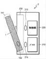
図23は、ホルダがクレードルに挿入された状態でチルトされる一例を図示した図面である。 FIG. 23 is a drawing illustrating an example in which the holder is tilted while being inserted into the cradle.
図23を参照すれば、ホルダ1がクレードル2の内部でチルトされている。ここで、該チルトは、ホルダ1がクレードル2に挿入された状態から一定角度傾けられることを意味する。 Referring to FIG. 23, the
図22に図示されているように、ホルダ1がクレードル2に完全に挿入される場合、ユーザは、喫煙をすることができない。言い換えれば、ホルダ1がクレードル2に完全に挿入されれば、ホルダ1にシガレットが挿入されない。従って、ホルダ1がクレードル2に完全に挿入された状態においては、ユーザが喫煙をすることができない。 As illustrated in FIG. 22, when the
図23に図示されているように、ホルダ1がチルトされれば、ホルダ1の末端141が外部に露出される。従って、ユーザは、末端141にシガレットを挿入し、生成されたエアロゾルを吸入(喫煙)することができる。チルト角θは、シガレットがホルダ1の末端141に挿入されるとき、シガレットが折れたり毀損されたりしないように、十分な角度が確保される。例えば、ホルダ1は、末端141に含まれたシガレット挿入孔全体が外部に露出される最小角度、またはそれより大きい角度にもチルトされる。例えば、チルト角θの範囲は、0゜超過180゜以下にもなり、望ましくは、10゜以上90゜以下にもなる。さらに望ましくは、チルト角θの範囲は、10゜以上20゜以下、10゜以上30゜以下、10゜以上40゜以下、10゜以上50゜以下、または10゜以上60゜以下にもなる。 As shown in FIG. 23, when the
また、ホルダ1がチルトされても、ホルダ1の端子170と、クレードル2の端子260は、互いに結合されている。従って、ホルダ1のヒータ130は、クレードル2のバッテリ210が供給する電力によって加熱されもする。従って、ホルダ1のバッテリ110の残量が少ないか、あるいはない場合にも、ホルダ1は、クレードル2のバッテリ210を利用し、エアロゾルを生成することができる。 Further, even if the
図23には、ホルダ1が1つの結着部材182を含み、クレードル2が2つの結着部材273,274を含む例が図示されている。例えば、結着部材182,273,274それぞれの位置は、図22を参照して説明した通りである。もし結着部材182,273,274が磁石であると仮定するならば、結着部材274の磁石強度が、結着部材273の磁石強度よりも大きくなる。従って、ホルダ1がチルトされても、結着部材182及び結着部材274により、ホルダ1は、クレードル2と完全に分離されない。 FIG. 23 shows an example in which the
また、端子170,260及び/または結着部材182,273,274により、ホルダ1がチルトされたと判断されれば、制御部220は、バッテリ210の電力を利用し、ホルダ1のヒータ130を加熱したり、バッテリ110を充電したりすることができる。 Further, if it is determined by the
図24A及び図24Bは、ホルダがクレードルに挿入された例を図示した図面である。 24A and 24B are drawings illustrating an example in which the holder is inserted into the cradle.
図24Aには、ホルダ1がクレードル2に完全に挿入された例が図示されている。ホルダ1がクレードル2に完全に挿入される場合、ユーザがホルダ1に接触することを最小化させるために、クレードル2の内部空間230が十分に確保されるようにも作製される。ホルダ1がクレードル2に完全に挿入されれば、制御部220は、ホルダ1のバッテリ110が充電されるように、バッテリ210の電力をホルダ1に供給する。 FIG. 24A illustrates an example in which the
図24Bには、ホルダ1がクレードル2に挿入された状態でチルトされた例が図示されている。ホルダ1がチルトされれば、制御部220は、ホルダ1のバッテリ110が充電されるか、あるいはホルダ1のヒータ130が加熱されるように、バッテリ210の電力をホルダ1に供給する。 FIG. 24B shows an example in which the
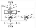
図25は、ホルダ及びクレードルが動作する一例について説明するためのフローチャートである。 FIG. 25 is a flowchart for explaining an example in which the holder and the cradle operate.
図25に図示されたエアロゾルを生成する方法は、図18に図示されたホルダ1、または図20に図示されたクレードル2において、時系列的に処理される段階で構成される。従って、以下で省略された内容であるとしても、図18に図示されたホルダ1、及び図20に図示されたクレードル2について、以上で記述された内容は、図25の方法にも適用されるということが分かる。 The method of producing the aerosol shown in FIG. 25 comprises the steps of being processed in chronological order in the
810段階において、ホルダ1は、クレードル2に挿入されたか否かということを判断する。例えば、制御部120は、ホルダ1及びクレードル2の端子170,260が互いに連結されたか否かということ、及び/または結着部材181,271,272が動作するか否かということにより、ホルダ1がクレードル2に挿入されたか否かということを判断することができる。 At
ホルダ1がクレードル2に挿入された場合には、820段階に進み、ホルダ1がクレードル2から分離された場合には、830段階に進む。 When the
820段階において、クレードル2は、ホルダ1がチルトされたか否かということを判断する。例えば、制御部220は、ホルダ1及びクレードル2の端子170,260が互いに連結されたか否かということ、及び/または結着部材182,273,274が動作するか否かということにより、ホルダ1がチルトされたか否かということを判断することができる。 At the 820 stage, the
820段階においては、クレードル2がホルダ1のチルトいかんを判断すると説明したが、それに限定されるものではない。言い換えれば、ホルダ1のチルトいかんは、ホルダ1の制御部120によっても判断される。 In the 820 stage, it has been explained that the
ホルダ1がチルトされた場合には、840段階に進み、ホルダ1がチルトされていない場合(すなわち、ホルダ1がクレードル2に完全に挿入された場合)には、870段階に進む。 If the
830段階において、ホルダ1は、ホルダ1の使用条件を満足するか否かということを判断する。例えば、制御部120は、バッテリ110の残量、及びホルダ1の他の構成が正常に動作することができるか否かということをチェックすることにより、使用条件が満足されたか否かということを判断することができる。 At the 830 stage, the
ホルダ1の使用条件が満足された場合には、840段階に進み、そうではない場合には、手続きを終了する。 If the conditions for using the
840段階において、ホルダ1は、ユーザに使用可能状態であるということを知らせる。例えば、制御部120は、ホルダ1のディスプレイに使用可能であるということを知らせる画面(image)を出力することもでき、ホルダ1のモータを制御し、振動信号を生成することもできる。 At
850段階において、ヒータ130が加熱される。一例として、ホルダ1がクレードル2から分離された場合、ホルダ1のバッテリ110の電力により、ヒータ130が加熱されもする。他の例として、ホルダ1がチルトされた場合、クレードル2のバッテリ210の電力により、ヒータ130が加熱されもする。 At the 850 stage, the
ホルダ1の制御部120、またはクレードル2の制御部220は、ヒータ130の温度をリアルタイムで確認し、ヒータ130に供給される電力の量、及びヒータ130に電力が供給される時間を調節することができる。例えば、制御部120,220は、ホルダ1に含まれた温度感知センサ、またはヒータ130の電気伝導性トラックを介して、ヒータ130の温度をリアルタイムで確認することができる。 The
860段階において、ホルダ1は、エアロゾル生成メカニズムを遂行する。例えば、制御部120,220は、ユーザがパフを遂行することによって変わるヒータ130の温度を確認し、ヒータ130に供給される電力の量を調節するか、あるいはヒータ130に電力の供給を中断することができる。また、制御部120,220は、ユーザのパフ回数を計数することができ、一定パフ回数(例えば、1,500回)に逹すれば、ホルダの掃除が必要であるということを知らせる情報を出力することができる。 At 860 steps,
870段階において、クレードル2は、ホルダ1の充電を行う。例えば、制御部220は、クレードル2のバッテリ210電力を、ホルダ1のバッテリ110に供給することにより、ホルダ1を充電させることができる。 At the 870 stage, the
一方、制御部120,220は、ユーザのパフ回数、またはホルダ1の動作時間により、ホルダ1の動作を停止させることもできる。以下、図26を参照し、制御部120,220がホルダ1の動作を停止させる一例について説明する。 On the other hand, the
図26は、ホルダが動作する他の例について説明するためのフローチャートである。 FIG. 26 is a flowchart for explaining another example in which the holder operates.
図26に図示されたエアロゾルを生成する方法は、図18に図示されたホルダ1、及び図20に図示されたクレードル2において、時系列的に処理される段階によって構成される。従って、以下で省略された内容であるとしても、図18に図示されたホルダ1、または図20に図示されたクレードル2について、以上で記述された内容は、図26の方法にも適用されるということが分かる。 The method of producing the aerosol shown in FIG. 26 consists of steps being processed in chronological order in the
910段階において、制御部120,220は、ユーザがパフしたか否かということを判断する。例えば、制御部120,220は、ホルダ1に含まれたパフ感知センサを介して、ユーザがパフしたか否かということを判断することができる。 At the 910th stage, the
920段階において、ユーザのパフにより、エアロゾルが生成される。制御部120,220が、ユーザのパフ、及びヒータ130の温度により、ヒータ130に供給される電力を調節することができることは、図25を参照して説明した通りである。また、制御部120,220は、ユーザのパフ回数を計数する。 At 920 steps, the user's puff produces an aerosol. As described with reference to FIG. 25, the
930段階において、制御部120,220は、ユーザのパフ回数が、パフ制限回数以上であるか否かということを判断する。例えば、パフ制限回数が14回に設定されたと仮定すれば、制御部120,220は、計数されたパフ回数が14回以上であるか否かということを判断する。 At the 930th stage, the
一方、ユーザのパフ回数がパフ制限回数に近接した場合(例えば、ユーザのパフ回数が12回である場合)、制御部120,220は、ディスプレイまたは振動モータを介して、警告信号を出力することができる。 On the other hand, when the number of puffs of the user is close to the limit number of puffs (for example, when the number of puffs of the user is 12), the
もしユーザのパフ回数がパフ制限回数以上である場合には、950段階に進み、ユーザのパフ回数がパフ制限回数より少ない場合には、940段階に進む。 If the number of puffs of the user is equal to or greater than the number of puff limits, the process proceeds to 950 steps, and if the number of puffs of the user is less than the number of puff limits, the process proceeds to 940 steps.
940段階において、制御部120,220は、ホルダ1が動作した時間が動作制限時間以上であるか否かということ判断する。ここで、ホルダ1が動作した時間は、ホルダが動作を始めた時点から現在まで累積された時間を意味する。例えば、動作制限時間が10分に設定されたと仮定すれば、制御部120,220は、ホルダ1が10分以上動作しているか否かということを判断する。 At the 940 stage, the
一方、ホルダ1の動作時間が動作制限時間に近接した場合(例えば、ホルダ1が8分間動作している場合)、制御部120,220は、ディスプレイまたは振動モータを介して、警告信号を出力することができる。 On the other hand, when the operation time of the
もしホルダ1が動作制限時間以上動作している場合には、950段階に進み、ホルダ1の動作時間が動作制限時間より少ない場合には、920段階に進む。 If the
950段階において、制御部120,220は、ホルダの動作を強制終了する。言い換えれば、制御部120,220は、ホルダのエアロゾル生成メカニズムを停止させる。例えば、制御部120,220は、ヒータ130に供給される電力を遮断することにより、ホルダの動作を強制終了することができる。 At the 950 stage, the
図27は、クレードルが動作する一例について説明するためのフローチャートである。 FIG. 27 is a flowchart for explaining an example in which the cradle operates.
図27に図示されたフローチャートは、図20に図示されたクレードル2において、時系列的に処理される段階によって構成される。従って、以下で省略された内容であるとしても、図20に図示されたクレードル2について以上で記述された内容は、図27のフローチャートにも適用されるということが分かる。 The flowchart illustrated in FIG. 27 is composed of steps processed in chronological order in the
図27には、図示されていないが、以下で説明するクレードル2の動作は、ホルダ1がクレードル2に挿入されたか否かということを問わずに遂行されもする。 Although not shown in FIG. 27, the operation of the
1010段階において、クレードル2の制御部220は、ボタン240が押されたか否かということを判断する。もしボタン240が押された場合には、1020段階に進み、ボタン240が押されていない場合には、1030段階に進む。 At the 1010 stage, the
1020段階において、クレードル2は、バッテリの状態を表示する。例えば、制御部220は、バッテリ210の現在状態(例えば、残量など)に係わる情報をディスプレイ250に出力することができる。 At the 1020 stage, the
1030段階において、クレードル2の制御部220は、クレードル2にケーブルが連結されたか否かということを判断する。例えば、制御部220は、クレードル2に含まれたインターフェース(例えば、USBポートなど)にケーブルが連結されたか否かということを判断する。もしクレードル2にケーブルが連結された場合には、1040段階に進み、そうではない場合には、手続きを終了する。 At the 1030 stage, the
1040段階において、クレードル2は、充電動作を遂行する。例えば、クレードル2は、連結されたケーブルを介して供給される電力を利用し、バッテリ210を充電する。 At the 1040 stage, the
図18を参照して説明した通り、ホルダ1には、シガレットが挿入される。シガレットは、エアロゾル生成物質を含み、加熱されたヒータ130によってエアロゾルが生成される。 As described with reference to FIG. 18, a cigarette is inserted into the
以下、図28ないし図30Fを参照し、ホルダ1に挿入されるシガレットの例について説明する。 Hereinafter, an example of a cigarette inserted into the
図28は、ホルダにシガレットが挿入された一例を図示した図面である。 FIG. 28 is a drawing illustrating an example in which a cigarette is inserted into the holder.
図28を参照すれば、シガレット3は、ケース140の末端141を介して、ホルダ1に挿入される。シガレット3が挿入されれば、ヒータ130は、シガレット3の内部に位置する。従って、加熱されたヒータ130により、シガレット3のエアロゾル生成物質が加熱され、それによってエアロゾルが生成される。 With reference to FIG. 28, the
シガレット3は、一般的な燃焼型シガレットと類似している。例えば、シガレット3は、エアロゾル生成物質を含む第1部分310と、フィルタなどを含む第2部分320とに区分される。一方、一実施形態によるシガレット3は、第2部分320に、エアロゾル生成物質を含んでもよい。例えば、顆粒またはカプセルの形態に作ったエアロゾル生成物質が、第2部分320にも挿入される。 The
ホルダ1の内部には第1部分310全体が挿入され、第2部分320は、外部にも露出される。または、ホルダ1の内部に、第1部分310の一部だけ挿入され、第1部分310及び第2部分320の一部が挿入されもする。 The entire
ユーザは、第2部分320を口にした状態でエアロゾルを吸入することができる。このとき、該エアロゾルは、外部空気と混合され、ユーザの口に伝達される。図28に図示されているように、外部空気は、シガレット3の表面に形成された少なくとも1つの孔(hole)を介しても流入され(1110)、ホルダ1に形成された少なくとも1つの空気通路を介しても流入される(1120)。例えば、ホルダ1に形成された空気通路は、ユーザによって開閉されるようにも作製される。 The user can inhale the aerosol with the
図29A及び図29Bは、シガレットの一例を図示した構成図である。 29A and 29B are block diagrams illustrating an example of a cigarette.
図29A及び図29Bを参照すれば、シガレット3は、タバコロッド310、第1フィルタセグメント321、冷却構造物322及び第2フィルタセグメント323を含む。図28を参照して説明した第1部分310は、タバコロッド310を含み、第2部分320は、第1フィルタセグメント321、冷却構造物322及び第2フィルタセグメント323を含む。 With reference to FIGS. 29A and 29B, the
一方、図29A及び図29Bを比較すれば、図29Bのシガレット3は、図29Aのシガレット3に比べ、第4ラッパ334をさらに含む。 On the other hand, comparing FIGS. 29A and 29B, the
ただし、図29A及び図29Bに図示されたシガレット3の構造は、一例に過ぎず、一部構成が省略されもする。例えば、シガレット3には、第1フィルタセグメント321、冷却構造物322及び第2フィルタセグメント323のうち1以上が含まれなくともよい。 However, the structure of the
タバコロッド310は、エアロゾル生成物質を含む。例えば、該エアロゾル生成物質は、グリセリン、プロピレングリコール、エチレングリコール、ジプロピレングリコール、ジエチレングリコール、トリエチレングリコール、テトラエチレングリコール及びオレイルアルコールのうち少なくとも一つを含んでもよい。タバコロッド310の長さは、約7mmないし15mmでもあるか、あるいは望ましくは、約12mmにもなる。また、タバコロッド310の直径は、7mmないし9mmでもあるか、あるいは望ましくは、約7.9mmでもある。タバコロッド310の長さ及び直径は、前述の数値範囲に限定されるものではない。 The
また、タバコロッド310は、風味剤、湿潤剤及び/またはアセテート化合物のような他の添加物質を含んでもよい。例えば、該風味剤は、甘草、ショ糖、果糖シロップ、イソ甘味剤(isosweet)、ココア、ラベンダ、シナモン、カルダモン、セロリ、フェヌグリーク、カスカリラ、白檀、ベルガモット、ゼラニウム、蜂蜜エッセンス、ローズオイル、バニラ、レモンオイル、オレンジオイル、ミントオイル、桂皮、キャラウェイ、コニャック、ジャスミン、カモマイル、メントール、桂皮、イランイラン、ザルビア、スペアミント、生姜、コリアンダまたはコーヒーなどを含んでもよい。また、該湿潤剤は、グリセリンまたはプロピレングリコールなどを含んでもよい。 The
一例として、タバコロッド310は、刻みタバコによっても充填される。ここで、該刻みタバコは、タバコシートを細かく粉砕することによっても生成される。 As an example, the
広いタバコシートが狭い空間のタバコロッド310に充填されるためには、タバコシートが容易に折り畳まれるようにする工程が追加して要求される。従って、タバコロッド310をタバコシートで充填することに比べ、タバコロッド310を刻みタバコで充填する方がさらに容易であり、タバコロッド310を生産する工程の生産性及び効率がさらに高くなる。 In order for the wide tobacco sheet to be filled in the
他の例として、タバコロッド310は、タバコシートが細切りされた複数のタバコ筋によっても充填される。例えば、タバコロッド310は、複数のタバコ筋が互いに同じ方向(平行)、または無作為に合わされても形成される。1本のタバコ筋は、横長が1mm、縦長が12mm、厚み(高さ)が0.1mmである直方体状にも製造されるが、それに限定されるものではない。 As another example, the
タバコロッド310がタバコシートによって充填されることに比べ、タバコ筋によって充填されたタバコロッド310は、さらに多量のエアロゾルが発生する。同一空間に充填されることを仮定すれば、タバコシートに比べ、タバコ筋がさらに広い表面積を保証する。広い表面積は、エアロゾル生成物質が外部空気と接触する機会がさらに多いということを意味する。従って、タバコロッド310がタバコ筋によって充填される場合、タバコシートに充填されたことに比べ、さらに多くのエアロゾルが生成される。 Compared to the
また、シガレット3をホルダ1から分離するとき、タバコ筋に充填されたタバコロッド310が、タバコシートに充填されたものに比べ、さらに容易に分離される。タバコシートに比べ、タバコ筋がヒータ130と接触して生成される摩擦力がさらに小さい。従って、タバコロッド310がタバコ筋によって充填される場合、タバコシートによって充填されたものに比べ、ホルダ1からさらに容易に分離される。 Further, when the
該タバコシートは、タバコ原料をスラリー形態に粉砕した後、該スラリーを乾燥させることによっても形成される。例えば、該スラリーには、エアロゾル生成物質が15ないし30%添加される。タバコ原料は、タバコ葉切れ、タバコ茎、タバコ処理中に発生されたタバコ粉じん、及び/またはタバコ葉の主要脇片ストリップでもある。また、タバコシートには、木材セルロース纎維のような他の添加剤が含有されてもよい。 The tobacco sheet is also formed by crushing the tobacco raw material into a slurry form and then drying the slurry. For example, 15 to 30% of aerosol-producing material is added to the slurry. Tobacco raw materials are also tobacco leaf breaks, tobacco stalks, tobacco dust generated during tobacco processing, and / or major flank strips of tobacco leaves. In addition, the tobacco sheet may contain other additives such as wood cellulose fiber.
第1フィルタセグメント321は、セルロースアセテートフィルタでもある。例えば、第1フィルタセグメント321は、内部に空洞を含むチューブ形態でもある。第1フィルタセグメント321の長さは、約7mmないし15mmでもあるか、あるいは望ましくは、約7mmにもなる。第1フィルタセグメント321の長さは、約7mmより短いが、少なくとも1つのシガレット要素(例えば、冷却要素、カプセル、アセテートフィルタなど)の機能が毀損されないほどの長さを有することが望ましい。第1フィルタセグメント321の長さは、前述の数値範囲に限定されるものではない。一方、第1フィルタセグメント321の長さは、拡張可能であり、第1フィルタセグメント321の長さにより、シガレット3全体長が調節される。 The
第2フィルタセグメント323も、セルロースアセテートフィルタでもある。例えば、第2フィルタセグメント323は、空洞を含むリセスフィルタによっても作製されるが、それに限定されるものではない。第2フィルタセグメント323の長さは、約5mmないし15mmでもあるか、あるいは望ましくは、約12mmにもなる。第2フィルタセグメント323の長さは、前述の数値範囲に限定されるものではない。 The
また、第2フィルタセグメント323には、少なくとも1つのカプセル324が含まれてもよい。ここで、カプセル324は、香料を含む内容液を被膜で覆い包んだ構造でもある。例えば、カプセル324は、球形または円筒状の形状を有することができる。カプセル324の直径は、2mm以上でもあるが、あるいは望ましくは、2〜4mmでもある。 In addition, the
カプセル324の被膜を形成する材料は、澱粉及び/またはゲル化剤でもある。例えば、ゲル化剤としては、ゲランガムやゼラチンが使用される。また、カプセル324の被膜を形成する材料として、ゲル化助剤がさらに利用される。ここで、該ゲル化助剤としては、例えば、塩化カルシウムが使用される。また、カプセル324の被膜を形成する材料として、可塑剤がさらに利用される。ここで、該可塑剤としては、グリセリン及び/またはソルビトールが利用される。また、カプセル324の被膜を形成する材料として、着色料がさらに利用される。 The material that forms the coating of the
例えば、カプセルの内容液に含まれる香料としては、メントール、植物の精油などが利用される。また、該内容液に含まれる香料の溶媒としては、例えば、重鎖脂肪酸トリグリセリド(重鎖)が利用される。また、該内容液は、色素、乳化剤、増粘剤のような他の添加剤を含んでもよい。 For example, as the fragrance contained in the content liquid of the capsule, menthol, essential oil of a plant, or the like is used. Further, as the solvent for the fragrance contained in the content liquid, for example, heavy chain fatty acid triglyceride (heavy chain) is used. In addition, the content liquid may contain other additives such as dyes, emulsifiers and thickeners.
冷却構造物322は、ヒータ130が、タバコロッド310を加熱することによって生成されたエアロゾルを冷却させる。従って、ユーザは、適当な温度に冷却されたエアロゾルを吸入することができる。冷却構造物322の長さは、約10mmないし20mmでもあるか、あるいは望ましくは、約14mmにもなる。冷却構造物322の長さは、前述の数値範囲に限定されるものではない。 In the
例えば、冷却構造物322は、ポリ乳酸によっても作製される。冷却構造物322は、単位面積当たり表面積(すなわち、エアロゾルと接触する表面積)を拡大させるために、多様な形態にも作製される。冷却構造物322の多様な例は、図21Aないし図30Fを参照して後述する。 For example, the
タバコロッド310及び第1フィルタセグメント321は、第1ラッパ331によっても包装される。例えば、第1ラッパ331は、耐油性を有する紙類包装材によっても作製される。 The
冷却構造物322及び第2フィルタセグメント323は、第2ラッパ332によっても包装される。また、シガレット3全体は、第3ラッパ333によっても再包装される。例えば、第2ラッパ332及び第3ラッパ333は、一般的な紙類包装材によっても作製される。選択的には、第2ラッパ332は、耐油ハード巻紙またはPLA加香紙でもある。また、第2ラッパ332は、第2フィルタセグメント323部分を包装し、追加して第2フィルタセグメント323及び冷却構造物322をさらに包装することができる。 The
図29Bを参照すれば、シガレット3は、第4ラッパ334を含んでもよい。タバコロッド310と第1フィルタセグメント321とのうち少なくとも一つは、第4ラッパ334によっても包装される。言い換えれば、タバコロッド310だけ第4ラッパ334によっても包装され、タバコロッド310及び第1フィルタセグメント321が第4ラッパ334によっても包装される。例えば、第4ラッパ334は、紙類包装材によっても作製される。 With reference to FIG. 29B, the
第4ラッパ334は、紙類包装材の一表面または両表面に、所定物質が塗布(または、コーティング)されることによって生成される。ここで、所定物質の例としては、シリコンが該当するが、それに限定されるものではない。シリコンは、温度による変化が少ない耐熱性、酸化されない耐酸化性、各種薬品に対する抵抗性、水に対する撥水性、または電気絶縁性などの特性を有する。ただし、シリコンではないとしても、前述の特性を有する物質であるならば、制限なしに第4ラッパ334に塗布(または、コーティング)される。 The
一方、図29Bには、シガレット3が第1ラッパ331及び第4ラッパ334をいずれも含むように図示されているが、それに限定されるものではない。言い換えれば、シガレット3が第1ラッパ331及び第4ラッパ334のうちいずれか一つだけ含んでもよい。 On the other hand, in FIG. 29B, the
第4ラッパ334は、シガレット3が燃焼される現象を防止することができる。例えば、タバコロッド310がヒータ130によって加熱されれば、シガレット3が燃焼される可能性がある。具体的には、タバコロッド310に含まれた物質のうちいずれか1つの発火点以上に温度が上昇する場合、シガレット3が燃焼される。そのような場合にも、第4ラッパ334は、不燃性物質を含むので、シガレット3が燃焼される現象が防止される。 The
また、第4ラッパ334は、シガレット3で生成される物質によってホルダ1が汚染されることを防止することができる。ユーザのパフにより、シガレット3内で液体物質が生成されもする。例えば、シガレット3で生成されたエアロゾルが外部空気によって冷却されることにより、液体物質(例えば、水分など)が生成される。第4ラッパ334が、タバコロッド310及び/または第1フィルタセグメント321を包装することにより、シガレット3内で生成された液体物質が、シガレット3の外部に漏れることが防止される。従って、ホルダ1のケース140などが、シガレット3で生成された液体物質によって汚染される現象が防止される。 Further, the
図30Aないし図30Fは、シガレットの冷却構造物の例を図示した図面である。 30A to 30F are drawings illustrating an example of a cigarette cooling structure.
例えば、図30Aないし図30Fに図示された冷却構造物は、純粋なポリ乳酸(PLA)によって生産された纎維を利用しても作製される。 For example, the cooling structures shown in FIGS. 30A to 30F can also be made using a fiber produced by pure polylactic acid (PLA).
一例として、フィルム(シート)を充填し、冷却構造物のフィルム(シート)を作製する場合、フィルム(シート)が外部の衝撃によって裂けてしまう。その場合、冷却構造物がエアロゾルを冷却する効果が低減される。 As an example, when a film (sheet) is filled to produce a film (sheet) of a cooling structure, the film (sheet) is torn by an external impact. In that case, the effect of the cooling structure on cooling the aerosol is reduced.
他の例として、押出成形などによって冷却構造物を作製する場合、構造物の切断などの工程が追加されることにより、工程の効率が低くなる。また、該冷却構造物を多様な形状で作製することにも限界がある。 As another example, when a cooled structure is produced by extrusion molding or the like, the efficiency of the process is lowered by adding a process such as cutting the structure. In addition, there is a limit to producing the cooling structure in various shapes.
一実施形態による冷却構造物を、ポリ乳酸纎維を利用して作製する(例えば、織造)ことにより、冷却構造物が外部衝撃によって変形されたり、機能を喪失したりするようになる危険性が低くなる。また、纎維を組み合わせる方式を変更することにより、多様な形状を有する冷却構造物を作製することができる。 By producing the cooling structure according to one embodiment using polylactic acid fiber (for example, weaving), there is a risk that the cooling structure will be deformed or lose its function due to an external impact. It gets lower. In addition, by changing the method of combining the fibers, it is possible to produce cooling structures having various shapes.
また、纎維を利用し、冷却構造物を作製することにより、エアロゾルと接触する表面積が拡大される。従って、冷却構造物のエアロゾル冷却効果がさらに向上する。 In addition, the surface area in contact with the aerosol is expanded by producing a cooling structure using the fiber. Therefore, the aerosol cooling effect of the cooling structure is further improved.
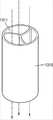
図30Aを参照すれば、冷却構造物1310は、円筒状にも作製され、冷却構造物1310の断面には、少なくとも1つの空気通路1311が形成されるようにも作製される。 With reference to FIG. 30A, the
図30Bを参照すれば、冷却構造物1320は、複数の纎維が互いに編み上げられた構造物にも作製される。このとき、エアロゾルは、纎維間に流れ、冷却構造物1320の形態によって渦流が形成される。形成された渦流は、冷却構造物1320において、エアロゾルが接触する面積を広げ、エアロゾルが冷却構造物1320内に留まる時間を延長させる。従って、加熱されたエアロゾルが、効果的に冷却される。 With reference to FIG. 30B, the
図30Cを参照すれば、冷却構造物1330は、複数個の束1331が集められた形態にも作製される。 With reference to FIG. 30C, the
図30Dを参照すれば、冷却構造物1340は、ポリ乳酸、刻みタバコまたは炭それぞれによって製造された顆粒によっても充填される。また、該顆粒は、ポリ乳酸、刻みタバコ及び炭の混合物によっても製造される。一方、該顆粒は、ポリ乳酸、刻みタバコ及び/または炭以外にも、エアロゾルの冷却効果を向上させることができる要素をさらに含んでもよい。 With reference to FIG. 30D, the
図30Eを参照すれば、冷却構造物1350は、第1断面1351及び第2断面1352を含んでもよい。 With reference to FIG. 30E, the
第1断面1351は、第1フィルタセグメント321と接境し、エアロゾルが流入する空隙を含む。第2断面1352は、第2フィルタセグメント323と接境し、エアロゾルが放出される空隙を含んでもよい。例えば、第1断面1351と第2断面1352は、直径が同一である単一空隙を含んでもよいが、第1断面1351と第2断面1352とに含まれる空隙の直径及び数は、それに制限されるものではない。 The
併せて、冷却構造物1350は、第1断面1351と第2断面1352との間に、複数の空隙が含まれた第3断面1353を含んでもよい。例えば、第3断面1353に含まれた複数の空隙の直径は、第1断面1351及び第2断面1352に含まれた空隙の直径よりも小さい。また、第3断面1353に含まれた空隙の数は、第1断面1351及び第2断面1352に含まれた空隙の数よりも多い。 In addition, the
図30Fを参照すれば、冷却構造物1360は、第1フィルタセグメント321と接境する第1断面1361、及び第2フィルタセグメント323と接境する第2断面1362を含んでもよい。また、冷却構造物1360は、1以上の管形要素1363を含んでもよい。例えば、管形要素1363は、第1断面1361と第2断面1362とを貫通ことができる。また、管形要素1363は、微細多孔質包装材によっても包装され、エアロゾルの冷却効果を向上させることができる充填材(例えば、図30Dを参照して説明した顆粒)によっても充填される。 With reference to FIG. 30F, the
前述のところによれば、ホルダは、シガレットを加熱することにより、エアロゾルを生成させることができる。また、該ホルダが独立して、または該ホルダがクレードルに挿入されてチルトされた状態でも、エアロゾルを生成させることができる。特に、該ホルダがチルトされた場合には、クレードルのバッテリの電力によってヒータが加熱される。 As mentioned above, the holder can generate an aerosol by heating the cigarette. Also, the aerosol can be generated independently or even when the holder is inserted into the cradle and tilted. In particular, when the holder is tilted, the heater is heated by the power of the cradle battery.
なお、前述の方法は、コンピュータで実行されるプログラムに作成可能であり、コンピュータで読み取り可能な記録媒体を利用し、前記プログラムを動作させる汎用デジタルコンピュータでも具現される。また、前述の方法で使用されたデータの構造は、コンピュータで読み取り可能な記録媒体に、さまざまな手段を介しても記録される。前記コンピュータで読み取り可能な記録媒体は、マグネチック保存媒体(例えば、ROM(read-only memory)、RAM(random access memory)、USB、フロッピーディスク、ハードディスクなど)、光学的判読媒体(例えば、CD−ROM(compact disc read only memory)、DVD(digital versatile disc)など)のような記録媒体を含む。 The above method can be created in a program executed by a computer, and is also embodied in a general-purpose digital computer that operates the program by using a recording medium that can be read by the computer. The data structure used in the above method is also recorded on a computer-readable recording medium via various means. The computer-readable recording medium includes a magnetic storage medium (for example, ROM (read-only memory), RAM (random access memory), USB, floppy disk, hard disk, etc.), and an optically readable medium (for example, CD-). Includes recording media such as ROM (compact disc read only memory), DVD (digital versatile disc), etc.
本実施形態と係わる技術分野で当業者であるならば、前述の記載の本質的な特性から外れない範囲で変形された形態に具現されるということを理解することができるであろう。従って、開示された方法は、限定的な観点ではなく、説明的な観点から考慮されなければならない。本発明の範囲は、前述の説明ではなく、特許請求の範囲に示されており、それと同等な範囲内にある全ての差異は、本発明に含まれたものであると解釈されなければならないのである。 Those skilled in the art in the art of this embodiment will appreciate that it will be embodied in a modified form to the extent that it does not deviate from the essential properties described above. Therefore, the disclosed method must be considered from a descriptive point of view, not from a limiting point of view. Since the scope of the present invention is shown in the claims rather than the above description, all differences within the equivalent scope must be construed as included in the present invention. be.
本実施形態は、シガレット内のエアロゾル生成物質を加熱してエアロゾルを生成する加熱式シガレットまたは加熱式エアロゾル生成装置に適用可能である。 The present embodiment is applicable to a heated cigarette or a heated aerosol generator that heats an aerosol-producing substance in a cigarette to generate an aerosol.
Claims (14)
Translated fromJapanese一側端部が前記通路に収容される前記シガレットに挿入されるように、前記一側端部が前記通孔を通過し、前記通路の内部に配置され、電気が印加されれば、前記シガレットを加熱するヒータと、を具備し、
前記突起は、前記通路の内壁面で互いに離隔されるように、複数個が前記通路の前記内壁面に固定されて配置され、隣接した前記突起の間に空気が通過する流路を形成する、エアロゾル生成装置。A passage for accommodating a cigarette, an opening opened to the outside at one end of the passage so that the cigarette can be inserted from the outside, a through hole connected to the other end of the passage, and a protrusion from the passage. , A hollow case comprising a protrusion that contacts a portion of the outer surface of the cigarette.
The cigarette if the one-sided end passes through the through hole, is placed inside the passage, and electricity is applied so that the one-sided end is inserted into the cigarette housed in the passage. Equipped with a heater to heat,
A plurality of the protrusions are fixedly arranged on the inner wall surface of the passage so as to be separated from each other on the inner wall surface of the passage, and form a flow path through which air passes between the adjacent protrusions. Aerosol generator.
一側端部が前記通路に収容される前記シガレットに挿入されるように、前記一側端部が前記通孔を通過し、前記通路の内部に配置され、電気が印加されれば、前記シガレットを加熱するヒータと、を具備し、
前記シガレットが前記通路に収容されたとき、前記突起が前記通路の他端に位置する前記シガレットの端部の外側面の一部分に接触するように、前記突起が前記通孔の前記他端において内側に突出する、エアロゾル生成装置。A passage for accommodating a cigarette, an opening opened to the outside at one end of the passage so that the cigarette can be inserted from the outside, a through hole connected to the other end of the passage, and a protrusion from the passage. , A hollow case comprising a protrusion that contacts a portion of the outer surface of the cigarette.
The cigarette if the one-sided end passes through the through hole, is placed inside the passage, and electricity is applied so that the one-sided end is inserted into the cigarette housed in the passage. Equipped with a heater to heat,
When the cigarette is housed in the passage, the protrusion is inside the other end of the through hole so that the protrusion contacts a portion ofthe outer surface of the end of the cigarette located at the other end of the passage.projecting, the aerosol generating device.
一側端部が前記通路に収容される前記シガレットに挿入されるように、前記一側端部が前記通孔を通過し、前記通路の内部に配置され、電気が印加されれば、前記シガレットを加熱するヒータと、を具備し、
前記ケースは、前記通路の前記他端を覆う底壁をさらに具備し、前記底壁は、前記通路に収容された前記シガレットの端部底面に接触し、前記通孔は、前記底壁を貫通するように形成され、
前記底壁は、前記シガレットの外側面と前記通路との空間と連結された連結通路を具備する、エアロゾル生成装置。A passage for accommodating a cigarette, an opening opened to the outside at one end of the passage so that the cigarette can be inserted from the outside, a through hole connected to the other end of the passage, and a protrusion from the passage. , A hollow case comprising a protrusion that contacts a portion of the outer surface of the cigarette.
If one side end passes through the through hole and is placed inside the passage and electricity is applied, the cigarette is inserted so that the one side end is inserted into the cigarette housed in the passage. Equipped with a heater to heat
The case further comprises a bottom wall covering the other end of the passage, the bottom wall in contact with the bottom surface of the end of the cigarette housed in the passage, and the through hole penetrating the bottom wall. Formed to
The bottom wall comprises a space and linked connection path between the passageway and the outer surface of thecigarette, the aerosol generating device.
一側端部が前記通路に収容される前記シガレットに挿入されるように、前記一側端部が前記通孔を通過し、前記通路の内部に配置され、電気が印加されれば、前記シガレットを加熱するヒータと、を具備し、
前記ケースは、前記通路の前記他端を覆う底壁をさらに具備し、前記底壁は、前記通路に収容された前記シガレットの端部底面に接触し、前記通孔は、前記底壁を貫通するように形成され、
前記底壁は、前記シガレットの前記端部底面を支持するように突出された底突起を具備する、エアロゾル生成装置。A passage for accommodating a cigarette, an opening opened to the outside at one end of the passage so that the cigarette can be inserted from the outside, a through hole connected to the other end of the passage, and a protrusion from the passage. , A hollow case comprising a protrusion that contacts a portion of the outer surface of the cigarette.
The cigarette if the one-sided end passes through the through hole, is placed inside the passage, and electricity is applied so that the one-sided end is inserted into the cigarette housed in the passage. Equipped with a heater to heat,
The case further comprises a bottom wall covering the other end of the passage, the bottom wall in contact with the bottom surface of the end of the cigarette housed in the passage, and the through hole penetrating the bottom wall. Formed to
The bottom wall comprises a protruded bottom protrusion to support theend portion bottom surface of thecigarette, the aerosol generating device.
一側端部が前記通路に収容される前記シガレットに挿入されるように、前記一側端部が前記通孔を通過し、前記通路の内部に配置され、電気が印加されれば、前記シガレットを加熱するヒータと、を具備し、
前記突起は、前記通路の長手方向に沿って、前記通路の一端から前記通路の他端まで延長し、前記突起が前記シガレットの外側面において、前記シガレットの中心に対して周囲方向に互いに離隔されるように、複数個が配置されることにより、隣接した前記突起の間に空気が通過する流路を形成する、エアロゾル生成装置。A passage for accommodating a cigarette, an opening opened to the outside at one end of the passage so that the cigarette can be inserted from the outside, a through hole connected to the other end of the passage, and a protrusion from the passage. , A hollow case comprising a protrusion that contacts a portion of the outer surface of the cigarette.
The cigarette if the one-sided end passes through the through hole, is placed inside the passage, and electricity is applied so that the one-sided end is inserted into the cigarette housed in the passage. Equipped with a heater to heat,
The protrusions extend from one end of the passage to the other end of the passage along the longitudinal direction of the passage, and the protrusions are separated from each other in the circumferential direction with respect to the center of the cigarette on the outer surface of the cigarette. An aerosol generator that forms a flow path through which air passes between the adjacent protrusions by arranging a plurality ofthe aerosols as described above.
一側端部が前記通路に収容される前記シガレットに挿入されるように、前記一側端部が前記通孔を通過し、前記通路の内部に配置され、電気が印加されれば、前記シガレットを加熱するヒータと、を具備し、
前記突起は、前記通路の内壁面で互いに離隔されるように、複数個が配置され、
前記シガレットが前記通路に収容されたとき、前記通路の他端に位置する前記シガレットの端部外側面の一部分に接触するように、前記通路から突出する端部突起をさらに具備する、エアロゾル生成装置。A passage for accommodating a cigarette, an opening opened to the outside at one end of the passage so that the cigarette can be inserted from the outside, a through hole connected to the other end of the passage, and a protrusion from the passage. , A hollow case comprising a protrusion that contacts a portion of the outer surface of the cigarette.
The cigarette if the one-sided end passes through the through hole, is placed inside the passage, and electricity is applied so that the one-sided end is inserted into the cigarette housed in the passage. Equipped with a heater to heat,
A plurality of the protrusions are arranged so as to be separated from each other on the inner wall surface of the passage.
When the cigarette is received in said passage so as to contact a portion of the end outer side of the cigarette located at the other end of said passage, further comprising an end projection projecting from thepassageway, the aerosol generating device ..
Applications Claiming Priority (9)
| Application Number | Priority Date | Filing Date | Title |
|---|---|---|---|
| KR20170046938 | 2017-04-11 | ||
| KR10-2017-0046938 | 2017-04-11 | ||
| KR10-2017-0077586 | 2017-06-19 | ||
| KR1020170077586AKR20180070436A (en) | 2016-12-16 | 2017-06-19 | Method and apparatus for generating generating aerosols |
| KR10-2017-0100888 | 2017-08-09 | ||
| KR1020170100888 | 2017-08-09 | ||
| KR1020170119664AKR102135893B1 (en) | 2016-12-16 | 2017-09-18 | Apparatus for generating aerosols |
| KR10-2017-0119664 | 2017-09-18 | ||
| PCT/KR2018/004179WO2018190606A1 (en) | 2017-04-11 | 2018-04-10 | Aerosol generating device |
Publications (2)
| Publication Number | Publication Date |
|---|---|
| JP2020516268A JP2020516268A (en) | 2020-06-11 |
| JP6930687B2true JP6930687B2 (en) | 2021-09-01 |
Family
ID=70227735
Family Applications (1)
| Application Number | Title | Priority Date | Filing Date |
|---|---|---|---|
| JP2019555204AActiveJP6930687B2 (en) | 2017-04-11 | 2018-04-10 | Aerosol generator |
Country Status (5)
| Country | Link |
|---|---|
| US (1) | US11197497B2 (en) |
| EP (1) | EP3610741A4 (en) |
| JP (1) | JP6930687B2 (en) |
| CN (1) | CN110494053B (en) |
| WO (1) | WO2018190606A1 (en) |
Families Citing this family (112)
| Publication number | Priority date | Publication date | Assignee | Title |
|---|---|---|---|---|
| KR102568030B1 (en)* | 2016-09-15 | 2023-08-18 | 필립모리스 프로덕츠 에스.에이. | aerosol generating device |
| RU2737855C1 (en) | 2017-03-30 | 2020-12-03 | Кей Ти Энд Джи Корпорейшн | Aerosol generation device and holder to accommodate device thereof |
| US12102131B2 (en) | 2017-04-11 | 2024-10-01 | Kt&G Corporation | Aerosol generating device and method for providing adaptive feedback through puff recognition |
| CN115024512B (en)* | 2017-04-11 | 2025-09-19 | 韩国烟草人参公社 | Aerosol generating device |
| JP6930687B2 (en)* | 2017-04-11 | 2021-09-01 | ケーティー・アンド・ジー・コーポレーション | Aerosol generator |
| KR20180124739A (en) | 2017-05-11 | 2018-11-21 | 주식회사 케이티앤지 | An aerosol generating device for controlling the temperature of a heater according to the type of cigarette and method thereof |
| US11178910B2 (en) | 2017-05-11 | 2021-11-23 | Kt&G Corporation | Vaporizer and aerosol generation device including same |
| KR20190049391A (en) | 2017-10-30 | 2019-05-09 | 주식회사 케이티앤지 | Aerosol generating apparatus having heater |
| JP6959429B2 (en) | 2017-09-06 | 2021-11-02 | ケーティー・アンド・ジー・コーポレーション | Aerosol generator |
| KR102138246B1 (en) | 2017-10-30 | 2020-07-28 | 주식회사 케이티앤지 | Vaporizer and aerosol generating apparatus comprising the same |
| KR102057215B1 (en) | 2017-10-30 | 2019-12-18 | 주식회사 케이티앤지 | Method and apparatus for generating aerosols |
| KR102057216B1 (en) | 2017-10-30 | 2019-12-18 | 주식회사 케이티앤지 | An apparatus for generating aerosols and A heater assembly therein |
| KR102138245B1 (en)* | 2017-10-30 | 2020-07-28 | 주식회사 케이티앤지 | Aerosol generating apparatus |
| KR102180421B1 (en) | 2017-10-30 | 2020-11-18 | 주식회사 케이티앤지 | Apparatus for generating aerosols |
| US12317923B2 (en) | 2017-10-30 | 2025-06-03 | Kt&G Corporation | Aerosol generating device |
| DK3750418T3 (en) | 2017-10-30 | 2024-04-02 | Kt & G Corp | AEROSOL GENERATION DEVICE AND METHOD OF CONTROLLING THE SAME |
| CN111182802A (en) | 2017-10-30 | 2020-05-19 | 韩国烟草人参公社 | Optical module and aerosol-generating device comprising the same |
| WO2019088559A2 (en) | 2017-10-30 | 2019-05-09 | 주식회사 케이티앤지 | Aerosol generating device |
| EP3704970B1 (en) | 2017-10-30 | 2025-01-01 | KT&G Corporation | Aerosol generating device |
| US11700884B2 (en) | 2017-10-30 | 2023-07-18 | Kt&G Corporation | Aerosol generation device and heater for aerosol generation device |
| KR102586323B1 (en)* | 2018-04-26 | 2023-10-10 | 니뽄 다바코 산교 가부시키가이샤 | Heater assembly and container |
| WO2019228037A1 (en)* | 2018-05-30 | 2019-12-05 | 深圳御烟实业有限公司 | Aerosol generating apparatus |
| CN119632302A (en) | 2018-07-31 | 2025-03-18 | 尤尔实验室有限公司 | Cartridge-based heat-without-burn vaporizer |
| CA3110469A1 (en) | 2018-08-22 | 2020-02-27 | Respira Technologies, Inc. | Electronic device for producing an aerosol for inhalation by a person |
| CN209376679U (en)* | 2018-09-28 | 2019-09-13 | 深圳市合元科技有限公司 | baking set |
| GB201817548D0 (en)* | 2018-10-29 | 2018-12-12 | Nerudia Ltd | Smoking substitute consumable |
| CN109619692B (en)* | 2019-01-23 | 2023-11-21 | 中国科学技术大学 | Method and device for heating non-combustible tobacco by interpolation type rotary friction |
| WO2020154690A1 (en) | 2019-01-25 | 2020-07-30 | Juul Labs, Inc. | Vaporizer device and cartridge |
| PL3934720T3 (en)* | 2019-03-05 | 2023-08-14 | Philip Morris Products S.A. | HOLDER FOR INHALATOR |
| KR20240091176A (en)* | 2019-03-11 | 2024-06-21 | 니코벤처스 트레이딩 리미티드 | Aerosol provision device |
| USD930897S1 (en)* | 2019-03-22 | 2021-09-14 | Joyetech Europe Holding Gmbh | Electronic cigarette |
| USD946823S1 (en)* | 2019-04-14 | 2022-03-22 | 14Th Round Inc. | Twisted mouthpiece |
| PL3958695T3 (en)* | 2019-04-23 | 2023-10-02 | Philip Morris Products S.A. | Aerosol generating device for use with an aerosol generating device |
| US20220225668A1 (en)* | 2019-04-29 | 2022-07-21 | Philip Morris Products S.A. | Aerosol-generating device with heating zone insulation |
| KR20220017901A (en)* | 2019-06-10 | 2022-02-14 | 필립모리스 프로덕츠 에스.에이. | Stable wrappers for aerosol-generating articles |
| EP3982768A1 (en)* | 2019-06-13 | 2022-04-20 | JT International SA | An aerosol generating system, an aerosol generating device and an aerosol generating article |
| CN110279147A (en) | 2019-06-28 | 2019-09-27 | 广东中烟工业有限责任公司 | A kind of cigarette heating device |
| JP7245331B2 (en)* | 2019-07-01 | 2023-03-23 | 日本たばこ産業株式会社 | Flavor sucker and insertion guide member |
| KR102480482B1 (en)* | 2019-07-05 | 2022-12-23 | 주식회사 케이티앤지 | Aerosol generating device |
| GB201909772D0 (en)* | 2019-07-08 | 2019-08-21 | Nicoventures Trading Ltd | Heating element |
| KR102397449B1 (en)* | 2019-07-23 | 2022-05-12 | 주식회사 케이티앤지 | Aerosol generating device |
| WO2021053165A1 (en)* | 2019-09-18 | 2021-03-25 | Jt International S.A. | Display bar graph and adaptive control |
| KR102343351B1 (en)* | 2019-10-11 | 2021-12-24 | 주식회사 케이티앤지 | Aerosol generating device |
| KR102363396B1 (en)* | 2019-10-16 | 2022-02-15 | 주식회사 케이티앤지 | Aerosol generating device including extractor |
| KR102431330B1 (en) | 2019-11-12 | 2022-08-10 | 주식회사 케이티앤지 | Aerosol generating device and operation method thereof |
| KR20210073373A (en)* | 2019-12-10 | 2021-06-18 | 주식회사 케이티앤지 | Aerosol generating article comprising tobacco sheet and aerosol generating system using the same |
| KR20220113854A (en)* | 2019-12-12 | 2022-08-17 | 퓨처 테크놀로지 가부시키가이샤 | Supporting member for heated tobacco and cartridge for heated tobacco |
| WO2021122705A1 (en)* | 2019-12-17 | 2021-06-24 | Philip Morris Products S.A. | Aerosol-generating device comprising a chamber for receiving an aerosol-generating article |
| WO2021127227A1 (en)* | 2019-12-17 | 2021-06-24 | Juul Labs, Inc. | Heating system for vaporizable material insert |
| EP4076068A1 (en) | 2019-12-20 | 2022-10-26 | JT International SA | Aerosol generation device with optical code detector |
| WO2021141246A1 (en)* | 2020-01-06 | 2021-07-15 | Kt&G Corporation | Aerosol generating device |
| WO2021141259A1 (en) | 2020-01-06 | 2021-07-15 | Kt&G Corporation | Aerosol generating system |
| KR102446416B1 (en)* | 2020-01-06 | 2022-09-23 | 주식회사 케이티앤지 | aerosol generating device |
| WO2021141251A1 (en) | 2020-01-06 | 2021-07-15 | Kt&G Corporation | Aerosol generating device |
| CN111278183B (en)* | 2020-02-26 | 2025-08-05 | 深圳麦时科技有限公司 | Heating element and electromagnetic heating baking device |
| KR102793114B1 (en) | 2020-02-27 | 2025-04-09 | 니뽄 다바코 산교 가부시키가이샤 | Smoking Systems, Devices, and Consumables |
| US20230100677A1 (en)* | 2020-03-11 | 2023-03-30 | Jt International Sa | Aerosol Generating System |
| US20210298353A1 (en)* | 2020-03-30 | 2021-09-30 | Hadek C. F. Ltd. | Smoking device with heat activated vents |
| KR102193315B1 (en)* | 2020-04-02 | 2020-12-22 | 정용채 | Portable health inhaling device with aerosol |
| CN212852497U (en)* | 2020-04-16 | 2021-04-02 | 深圳麦时科技有限公司 | Electrically heated aerosol-forming device |
| CN111420621B (en)* | 2020-04-21 | 2025-06-17 | 深圳麦时科技有限公司 | Aerosol Generating Device |
| CN111436663A (en)* | 2020-05-18 | 2020-07-24 | 南通金源新材料有限公司 | Aerosol generating device with surrounding type airflow |
| JP2023530908A (en)* | 2020-06-30 | 2023-07-20 | ジェイティー インターナショナル エス.エイ. | Aerosol generator for heating smokable material |
| CN111972712B (en)* | 2020-07-07 | 2024-08-27 | 深圳麦时科技有限公司 | Aerosol generating device |
| EP4179885A4 (en)* | 2020-07-09 | 2024-04-10 | Japan Tobacco Inc. | Main body unit of aerosol generation device, aerosol generation device, and non-combustion suction device |
| KR20230042042A (en)* | 2020-07-21 | 2023-03-27 | 제이티 인터내셔널 소시에떼 아노님 | aerosol generating device |
| CN213604392U (en)* | 2020-09-25 | 2021-07-06 | 深圳市合元科技有限公司 | Aerosol generating device |
| JP6890203B1 (en) | 2020-09-30 | 2021-06-18 | 日本たばこ産業株式会社 | Power supply unit of aerosol generator |
| EP4225086A1 (en)* | 2020-10-06 | 2023-08-16 | JT International S.A. | Aerosol generating device with a plurality of identical ring-shaped susceptors |
| JP7637695B2 (en)* | 2020-10-12 | 2025-02-28 | 日本たばこ産業株式会社 | Suction device, control method, and program |
| JP2021010376A (en)* | 2020-10-14 | 2021-02-04 | 株式会社東亜産業 | Support member for electronic compatible cartridge and electronic cigarette compatible cartridge including the same |
| US20220132920A1 (en)* | 2020-11-01 | 2022-05-05 | Respira Technologies, Inc. | Electronic devices and liquids for aerosolizing and inhaling therewith |
| KR102637742B1 (en)* | 2020-11-25 | 2024-02-19 | 주식회사 케이티앤지 | Aerosol generating device |
| CN214629887U (en)* | 2020-11-26 | 2021-11-09 | 深圳麦时科技有限公司 | Heater and heating atomization device |
| KR102574395B1 (en) | 2020-12-03 | 2023-09-04 | 주식회사 케이티앤지 | Aerosol generating device |
| EP4260718A1 (en)* | 2020-12-09 | 2023-10-18 | Japan Tobacco Inc. | Flavor inhaler |
| WO2022123769A1 (en)* | 2020-12-11 | 2022-06-16 | 日本たばこ産業株式会社 | Flavor inhaler |
| KR102589998B1 (en)* | 2021-01-29 | 2023-10-16 | 주식회사 케이티앤지 | Aerosol generating device |
| CN215455416U (en)* | 2021-01-29 | 2022-01-11 | 深圳麦克韦尔科技有限公司 | Aerosol generating device |
| GB202101466D0 (en)* | 2021-02-03 | 2021-03-17 | Nicoventures Trading Ltd | Non-combustible aerosol provision |
| CN112869231A (en)* | 2021-03-10 | 2021-06-01 | 云南中烟工业有限责任公司 | Gas-containing particles, preparation method and application thereof |
| CN117295417A (en)* | 2021-04-28 | 2023-12-26 | 日本烟草产业株式会社 | Smoking system, kit of devices, consumable, composition, and method of obtaining end-to-end feel and end-to-end predictability |
| KR20230172557A (en)* | 2021-04-28 | 2023-12-22 | 니뽄 다바코 산교 가부시키가이샤 | Flavor aspirator and smoking system |
| KR20240006522A (en)* | 2021-05-10 | 2024-01-15 | 제이티 인터내셔널 소시에떼 아노님 | Aerosol generating devices and sets |
| EP4355146A1 (en)* | 2021-06-18 | 2024-04-24 | Nicoventures Trading Limited | Aerosol generating device |
| KR102573818B1 (en)* | 2021-06-23 | 2023-08-31 | 주식회사 케이티앤지 | Device for generating aerosol |
| WO2023275948A1 (en)* | 2021-06-28 | 2023-01-05 | 日本たばこ産業株式会社 | Aerosol generation system |
| JP7518295B2 (en)* | 2021-06-28 | 2024-07-17 | 日本たばこ産業株式会社 | Aerosol Generation System |
| CN115701330A (en)* | 2021-08-02 | 2023-02-10 | 深圳市合元科技有限公司 | Aerosol generating device |
| JP2024537218A (en)* | 2021-10-13 | 2024-10-10 | フィリップ・モーリス・プロダクツ・ソシエテ・アノニム | Aerosol generating device with article retention |
| JP2024536571A (en)* | 2021-10-20 | 2024-10-04 | 深▲せん▼麦克韋爾科技有限公司 | Aerosol fixing device and aerosol generating device |
| CN216723136U (en)* | 2021-11-03 | 2022-06-14 | 深圳麦时科技有限公司 | Heating assembly and aerosol generating device |
| EP4429492A1 (en)* | 2021-11-08 | 2024-09-18 | Nicoventures Trading Limited | Aerosol generating system |
| KR102774416B1 (en)* | 2021-11-11 | 2025-03-04 | 주식회사 케이티앤지 | Aerosol generating device |
| EP4312613A4 (en)* | 2021-11-11 | 2024-10-16 | KT&G Corporation | AEROSOL GENERATING DEVICE WITH SUPPORT FOR PROVIDING AIR FOR AN AEROSOL GENERATING ARTICLE |
| WO2023085816A1 (en)* | 2021-11-11 | 2023-05-19 | Kt&G Corporation | Aerosol generating device |
| EP4312615A4 (en)* | 2021-11-11 | 2024-10-02 | KT&G Corporation | Aerosol generating device |
| EP4437871A4 (en)* | 2021-11-22 | 2025-09-17 | Japan Tobacco Inc | FLAVOR INHALER AND FLAVOR INHALATION SYSTEM |
| KR102688713B1 (en)* | 2021-11-23 | 2024-07-29 | 주식회사 케이티앤지 | Device for generating aerosol |
| EP4449907A1 (en)* | 2021-12-15 | 2024-10-23 | Japan Tobacco Inc. | Flavour inhaler, and smoking system |
| KR102713766B1 (en)* | 2022-01-19 | 2024-10-07 | 주식회사 케이티앤지 | Device for generating aerosol |
| WO2023148910A1 (en)* | 2022-02-04 | 2023-08-10 | 日本たばこ産業株式会社 | Flavor inhaler, and smoking system |
| US20230337735A1 (en) | 2022-04-22 | 2023-10-26 | Qnovia, Inc. | Electronic devices for aerosolizing and inhaling liquid |
| WO2023208963A1 (en)* | 2022-04-29 | 2023-11-02 | Nicoventures Trading Limited | Aerosol provision device |
| EP4525646A1 (en)* | 2022-05-16 | 2025-03-26 | Philip Morris Products S.A. | Heater assembly with heater mounting |
| KR20240044117A (en)* | 2022-09-28 | 2024-04-04 | 주식회사 케이티앤지 | Heating assembly and aerosol generating device comprising the same |
| JPWO2024095387A1 (en)* | 2022-11-02 | 2024-05-10 | ||
| WO2024261959A1 (en)* | 2023-06-22 | 2024-12-26 | 日本たばこ産業株式会社 | Smoking system |
| WO2025046701A1 (en)* | 2023-08-28 | 2025-03-06 | 日本たばこ産業株式会社 | Aerosol generation device |
| WO2025141056A1 (en)* | 2023-12-28 | 2025-07-03 | Nicoventures Trading Limited | Aerosol provision device |
| CN120226790A (en)* | 2023-12-28 | 2025-07-01 | 尼科创业贸易有限公司 | Aerosol supply device |
| EP4602949A1 (en)* | 2024-02-15 | 2025-08-20 | Imperial Tobacco Limited | Aerosol generating apparatus |
Family Cites Families (239)
| Publication number | Priority date | Publication date | Assignee | Title |
|---|---|---|---|---|
| US2638904A (en) | 1950-04-18 | 1953-05-19 | Amos M Mitchell | Cigarette holder |
| CH310239A (en) | 1953-07-24 | 1955-10-15 | Vautier Freres & Cie Sa | Filter, especially for cigarettes, cigarette holders and pipes. |
| US4474191A (en)* | 1982-09-30 | 1984-10-02 | Steiner Pierre G | Tar-free smoking devices |
| DE3302518A1 (en) | 1983-01-26 | 1984-07-26 | T.R.-Plast GmbH & Co Kunststoff-Verarbeitung, 8430 Neumarkt | Apparatus for cleaning and polishing tobacco pipes |
| US4637407A (en) | 1985-02-28 | 1987-01-20 | Cangro Industries, Inc. | Cigarette holder |
| US5144962A (en) | 1989-12-01 | 1992-09-08 | Philip Morris Incorporated | Flavor-delivery article |
| US5388594A (en) | 1991-03-11 | 1995-02-14 | Philip Morris Incorporated | Electrical smoking system for delivering flavors and method for making same |
| US5479948A (en) | 1993-08-10 | 1996-01-02 | Philip Morris Incorporated | Electrical smoking article having continuous tobacco flavor web and flavor cassette therefor |
| US5249586A (en) | 1991-03-11 | 1993-10-05 | Philip Morris Incorporated | Electrical smoking |
| US5591368A (en) | 1991-03-11 | 1997-01-07 | Philip Morris Incorporated | Heater for use in an electrical smoking system |
| US5505214A (en) | 1991-03-11 | 1996-04-09 | Philip Morris Incorporated | Electrical smoking article and method for making same |
| US5240012A (en) | 1991-11-13 | 1993-08-31 | Philip Morris Incorporated | Carbon heat smoking article with reusable body |
| US5465738A (en) | 1992-04-09 | 1995-11-14 | Music City Marketing, Inc. | Smoking system |
| US5498855A (en)* | 1992-09-11 | 1996-03-12 | Philip Morris Incorporated | Electrically powered ceramic composite heater |
| US5666977A (en) | 1993-06-10 | 1997-09-16 | Philip Morris Incorporated | Electrical smoking article using liquid tobacco flavor medium delivery system |
| CR4906A (en) | 1993-09-10 | 1994-09-09 | Philip Morris Prod | ELECTRIC SMOKING SYSTEM TO DISTRIBUTE FLAVORS AND METHOD FOR ITS MANUFACTURE |
| US5878752A (en) | 1996-11-25 | 1999-03-09 | Philip Morris Incorporated | Method and apparatus for using, cleaning, and maintaining electrical heat sources and lighters useful in smoking systems and other apparatuses |
| JP3845921B2 (en) | 1996-11-29 | 2006-11-15 | 株式会社デンソー | Brake hydraulic pressure control device |
| JP3327826B2 (en) | 1997-12-05 | 2002-09-24 | 日本たばこ産業株式会社 | Flavor producing articles and flavor producing instruments |
| RU2130744C1 (en) | 1998-09-09 | 1999-05-27 | Ставрулов Игорь Анатольевич | Tobacco article and method for packaging tobacco articles |
| EP1130982B1 (en) | 1998-11-10 | 2006-11-29 | Philip Morris Products Inc. | Brush cleaning unit for the heater fixture of a smoking device |
| US6053176A (en) | 1999-02-23 | 2000-04-25 | Philip Morris Incorporated | Heater and method for efficiently generating an aerosol from an indexing substrate |
| US6532965B1 (en) | 2001-10-24 | 2003-03-18 | Brown & Williamson Tobacco Corporation | Smoking article using steam as an aerosol-generating source |
| US6615840B1 (en) | 2002-02-15 | 2003-09-09 | Philip Morris Incorporated | Electrical smoking system and method |
| GB0209690D0 (en) | 2002-04-27 | 2002-06-05 | British American Tobacco Co | Improvements relating to smoking articles and smokable filler materials therefor |
| US20050172976A1 (en) | 2002-10-31 | 2005-08-11 | Newman Deborah J. | Electrically heated cigarette including controlled-release flavoring |
| US6810883B2 (en) | 2002-11-08 | 2004-11-02 | Philip Morris Usa Inc. | Electrically heated cigarette smoking system with internal manifolding for puff detection |
| US7293565B2 (en) | 2003-06-30 | 2007-11-13 | Philip Morris Usa Inc. | Electrically heated cigarette smoking system |
| US7392809B2 (en) | 2003-08-28 | 2008-07-01 | Philip Morris Usa Inc. | Electrically heated cigarette smoking system lighter cartridge dryer |
| JP2006320286A (en) | 2005-05-20 | 2006-11-30 | Tokai Corp | Apparatus for heating pseudo-tobacco and pseudo-tobacco |
| KR100636287B1 (en) | 2005-07-29 | 2006-10-19 | 주식회사 케이티앤지 | Electric Cigarette Heaters |
| CA2641167A1 (en) | 2006-02-03 | 2007-08-16 | Master Lock Company Llc | User adjustable storage arrangement |
| CN201067079Y (en) | 2006-05-16 | 2008-06-04 | 韩力 | Simulated aerosol inhaler |
| JP2008035742A (en) | 2006-08-03 | 2008-02-21 | British American Tobacco Pacific Corporation | Evaporating apparatus |
| IES20070633A2 (en) | 2006-09-05 | 2008-09-17 | Oglesby & Butler Res & Dev Ltd | A container comprising vaporisable matter for use in a vaporising device for vaporising a vaporisable constituent thereof |
| US7861726B1 (en) | 2006-11-27 | 2011-01-04 | Lukasavitz Steven J | Filtration device for tobacco products |
| CN1973706A (en)* | 2006-11-29 | 2007-06-06 | 郭德荣 | Cigarette ash pen |
| GB0703152D0 (en)* | 2007-02-17 | 2007-03-28 | Rowley Thomas J | Anti-smoking device |
| CA2963423C (en) | 2007-03-30 | 2020-07-28 | Philip Morris Products S.A. | Device and method for delivery of a medicament |
| EP1989946A1 (en) | 2007-05-11 | 2008-11-12 | Rauchless Inc. | Smoking device, charging means and method of using it |
| JP4728306B2 (en) | 2007-09-18 | 2011-07-20 | トーカロ株式会社 | Electrostatic chuck member and manufacturing method thereof |
| EP2110034A1 (en) | 2008-04-17 | 2009-10-21 | Philip Morris Products S.A. | An electrically heated smoking system |
| EP2113178A1 (en) | 2008-04-30 | 2009-11-04 | Philip Morris Products S.A. | An electrically heated smoking system having a liquid storage portion |
| KR100965099B1 (en) | 2008-07-07 | 2010-06-22 | (주)휴맥스 | Case fasteners |
| EP2201850A1 (en) | 2008-12-24 | 2010-06-30 | Philip Morris Products S.A. | An article including identification information for use in an electrically heated smoking system |
| CN101444335B (en) | 2008-12-31 | 2011-05-25 | 广东中烟工业有限责任公司 | a safe cigarette |
| JP4739433B2 (en)* | 2009-02-07 | 2011-08-03 | 和彦 清水 | Smokeless smoking jig |
| JP2011087569A (en) | 2009-05-15 | 2011-05-06 | Jbs:Kk | Electronic cigarette and charging unit |
| EP2253233A1 (en) | 2009-05-21 | 2010-11-24 | Philip Morris Products S.A. | An electrically heated smoking system |
| US8464726B2 (en) | 2009-08-24 | 2013-06-18 | R.J. Reynolds Tobacco Company | Segmented smoking article with insulation mat |
| EP2316286A1 (en) | 2009-10-29 | 2011-05-04 | Philip Morris Products S.A. | An electrically heated smoking system with improved heater |
| GB201001944D0 (en) | 2010-02-05 | 2010-03-24 | Kind Consumer Ltd | A simulated smoking device |
| CA2789362C (en) | 2010-02-24 | 2014-05-27 | Japan Tobacco Inc. | Flavor inhalation pipe |
| KR20110009632U (en) | 2010-04-05 | 2011-10-12 | 오상택 | Sterilizing and charging apparatus for electronic cigarette |
| US9743691B2 (en) | 2010-05-15 | 2017-08-29 | Rai Strategic Holdings, Inc. | Vaporizer configuration, control, and reporting |
| US20110290248A1 (en) | 2010-05-25 | 2011-12-01 | Steven Michael Schennum | Aerosol Generator |
| GB201016387D0 (en) | 2010-09-29 | 2010-11-10 | Filtrona Int Ltd | Tobacco smoke filter |
| EP2454956A1 (en) | 2010-11-19 | 2012-05-23 | Philip Morris Products S.A. | An electrically heated smoking system comprising at least two units |
| EP2460422A1 (en) | 2010-12-03 | 2012-06-06 | Philip Morris Products S.A. | An aerosol generating system with provention of condensate leakage |
| EP2468118A1 (en) | 2010-12-24 | 2012-06-27 | Philip Morris Products S.A. | An aerosol generating system with means for disabling a consumable |
| EP2468117A1 (en) | 2010-12-24 | 2012-06-27 | Philip Morris Products S.A. | An aerosol generating system having means for determining depletion of a liquid substrate |
| AT510837B1 (en) | 2011-07-27 | 2012-07-15 | Helmut Dr Buchberger | INHALATORKOMPONENTE |
| CN103491815B (en) | 2011-02-11 | 2016-01-20 | 巴特马克有限公司 | Inhalator assembly |
| GB201104475D0 (en) | 2011-03-16 | 2011-04-27 | Filtrona Filter Prod Dev Co | Tobacco smoke filter |
| GB201104788D0 (en) | 2011-03-22 | 2011-05-04 | British American Tobacco Co | Smoking article |
| KR101098112B1 (en) | 2011-03-30 | 2011-12-26 | 한정환 | System to control the electronic cigarette according to the number of smoking and the smoking time |
| KR20120121314A (en) | 2011-04-26 | 2012-11-05 | 하종석 | cartridge of inhalation type anti-smoking preparation and cartridge case for the same |
| US9078473B2 (en) | 2011-08-09 | 2015-07-14 | R.J. Reynolds Tobacco Company | Smoking articles and use thereof for yielding inhalation materials |
| GB201207054D0 (en) | 2011-09-06 | 2012-06-06 | British American Tobacco Co | Heating smokeable material |
| KR20130027909A (en) | 2011-09-08 | 2013-03-18 | 이영인 | Cartridge for electronic cigarette with enhanced inhaling flavor |
| KR102112991B1 (en) | 2011-10-25 | 2020-05-21 | 필립모리스 프로덕츠 에스.에이. | Aerosol generating device with heater assembly |
| SG11201402068YA (en) | 2011-11-07 | 2014-06-27 | Philip Morris Products Sa | Smoking article with colour change segment |
| AU2012342570B2 (en)* | 2011-11-21 | 2016-11-24 | Philip Morris Products S.A. | Ejector for an aerosol-generating device |
| CN202407082U (en) | 2011-12-23 | 2012-09-05 | 刘秋明 | electronic cigarette nozzle |
| EP2625974A1 (en) | 2012-02-13 | 2013-08-14 | Philip Morris Products S.A. | Aerosol-generating article having a flavour-generating component |
| EP2609820A1 (en) | 2011-12-30 | 2013-07-03 | Philip Morris Products S.A. | Detection of aerosol-forming substrate in an aerosol generating device |
| MY170381A (en) | 2011-12-30 | 2019-07-27 | Philip Morris Products Sa | Smoking article with front-plug and aerosol-forming substrate and method |
| AR089602A1 (en) | 2011-12-30 | 2014-09-03 | Philip Morris Products Sa | AEROSOL GENERATOR ARTICLE FOR USE WITH AN AEROSOL GENERATOR DEVICE |
| EP2797445B1 (en) | 2011-12-30 | 2016-05-04 | Philip Morris Products S.a.s. | Aerosol generating device with improved temperature distribution |
| JP6062457B2 (en) | 2011-12-30 | 2017-01-18 | フィリップ・モーリス・プロダクツ・ソシエテ・アノニム | Aerosol generator with airflow detection |
| BR112014012734B1 (en) | 2011-12-30 | 2021-03-02 | Philip Morris Products S.A. | aerosol generation system and method for providing aerosol delivery data to an end user |
| EP2609821A1 (en) | 2011-12-30 | 2013-07-03 | Philip Morris Products S.A. | Method and apparatus for cleaning a heating element of aerosol-generating device |
| EP2625975A1 (en) | 2012-02-13 | 2013-08-14 | Philip Morris Products S.A. | Aerosol-generating article having an aerosol-cooling element |
| PL2797450T3 (en) | 2011-12-30 | 2018-03-30 | Philip Morris Products S.A. | Smoking article with front-plug and method |
| CA2862451C (en) | 2012-01-03 | 2020-02-18 | Philip Morris Products S.A. | An aerosol generating device and system with improved airflow |
| MX352722B (en) | 2012-01-03 | 2017-12-06 | Philip Morris Products Sa | Non-rolling aerosol-generating device. |
| HUE030009T2 (en) | 2012-01-03 | 2017-04-28 | Philip Morris Products Sa | Aerosol-generating device and system |
| AR089607A1 (en) | 2012-01-03 | 2014-09-03 | Philip Morris Products Sa | ENERGY SUPPLY SYSTEM FOR A PORTABLE AEROSOL GENERATOR DEVICE |
| BR112014016425B1 (en) | 2012-01-03 | 2020-12-15 | Philip Morris Products S.A | AEROSOL GENERATION SYSTEM |
| US9289014B2 (en) | 2012-02-22 | 2016-03-22 | Altria Client Services Llc | Electronic smoking article and improved heater element |
| JP2015107056A (en) | 2012-03-16 | 2015-06-11 | 日本たばこ産業株式会社 | Non-heating type flavor sucker |
| US20130340775A1 (en) | 2012-04-25 | 2013-12-26 | Bernard Juster | Application development for a network with an electronic cigarette |
| US20130284192A1 (en) | 2012-04-25 | 2013-10-31 | Eyal Peleg | Electronic cigarette with communication enhancements |
| US11517042B2 (en) | 2012-04-25 | 2022-12-06 | Altria Client Services Llc | Digital marketing applications for electronic cigarette users |
| GB2502054A (en) | 2012-05-14 | 2013-11-20 | Nicoventures Holdings Ltd | Electronic smoking device |
| US9427023B2 (en) | 2012-06-20 | 2016-08-30 | Huizhou Kimree Technology Co., Ltd., Shenzhen Branch | Electronic cigarette and electronic cigarette device |
| AR091509A1 (en) | 2012-06-21 | 2015-02-11 | Philip Morris Products Sa | ARTICLE TO SMOKE TO BE USED WITH AN INTERNAL HEATING ELEMENT |
| KR20140015774A (en) | 2012-07-24 | 2014-02-07 | 삼성전기주식회사 | Hydrodynamic bearing assembly and motor including the same |
| KR101383577B1 (en) | 2012-07-26 | 2014-04-17 | 신종수 | Mobile apparatus for charging electronic cigarette |
| AU2012388105B2 (en) | 2012-08-24 | 2017-01-12 | Huizhou Kimree Technology Co., Ltd. | Electronic cigarette apparatus |
| EP2701268A1 (en) | 2012-08-24 | 2014-02-26 | Philip Morris Products S.A. | Portable electronic system including charging device and method of charging a secondary battery |
| CA2882464C (en) | 2012-08-24 | 2017-07-25 | Kimree Hi-Tech Inc. | Electronic cigarette apparatus |
| EP2732713A4 (en) | 2012-08-31 | 2015-07-22 | Kimree Hi Tech Inc | Electronic cigarette with multiple tastes |
| CN202774134U (en) | 2012-09-21 | 2013-03-13 | 刘秋明 | Electronic cigarette case and electronic cigarette device |
| US9854841B2 (en) | 2012-10-08 | 2018-01-02 | Rai Strategic Holdings, Inc. | Electronic smoking article and associated method |
| KR200466757Y1 (en) | 2012-11-01 | 2013-05-06 | (주)잔티아시아 | Smart electronic cigarette with multifunction control means |
| TWI629007B (en) | 2012-12-21 | 2018-07-11 | Philip Morris Products S. A. | Smoking article comprising an airflow directing element |
| HUE036091T2 (en) | 2012-12-28 | 2018-06-28 | Philip Morris Products Sa | Heating assembly for an aerosol generating system |
| UA118101C2 (en) | 2013-02-22 | 2018-11-26 | Олтріа Клайєнт Сервісиз Ллк | Electronic smoking article |
| US10031183B2 (en) | 2013-03-07 | 2018-07-24 | Rai Strategic Holdings, Inc. | Spent cartridge detection method and system for an electronic smoking article |
| US9560883B2 (en) | 2013-03-15 | 2017-02-07 | Altria Client Services Llc | Electronic smoking articles |
| US20140299137A1 (en) | 2013-04-05 | 2014-10-09 | Johnson Creek Enterprises, LLC | Electronic cigarette and method and apparatus for controlling the same |
| US9629394B2 (en) | 2013-04-09 | 2017-04-25 | Alan Benet Aronie | Portable vaporizer with central pin heater having heat diffuser-mixer blades |
| FR3004368B1 (en) | 2013-04-15 | 2015-09-25 | Aircelle Sa | SOLDERING WITHOUT TOOLS |
| CN104106842B (en) | 2013-04-16 | 2019-02-12 | 惠州市吉瑞科技有限公司 | The method of electronic cigarette and processing electronic cigarette smoking data |
| CN203457802U (en) | 2013-05-07 | 2014-03-05 | 深圳市合元科技有限公司 | Oil-leakage-prevention electronic cigarette atomizer and electronic cigarette |
| ES2670574T3 (en) | 2013-05-20 | 2018-05-31 | Nu Mark Innovations Ltd | Development of applications for a network associated with an electronic cigarette |
| EP2999367B8 (en) | 2013-05-23 | 2020-12-30 | Altria Client Services LLC | Digital marketing application for electronic cigarette users |
| WO2015009903A2 (en) | 2013-07-18 | 2015-01-22 | Quitbit, Inc. | Lighter and method for monitoring smoking behavior |
| GB2518598B (en) | 2013-08-30 | 2016-06-01 | Nicoventures Holdings Ltd | Apparatus with battery power control |
| KR101516304B1 (en) | 2013-09-12 | 2015-05-04 | 김한기 | Electrical Cigarette |
| EP3222159B1 (en) | 2013-09-30 | 2020-06-17 | Japan Tobacco Inc. | Non-burning type flavor inhaler |
| US20150100441A1 (en) | 2013-10-04 | 2015-04-09 | Loec, Inc. | Retail engine for electronic smoking device |
| CN203563687U (en)* | 2013-11-05 | 2014-04-30 | 湖北中烟工业有限责任公司 | Heat conduction type low-temperature cigarette heat preservation sleeve |
| CN203633505U (en) | 2013-11-29 | 2014-06-11 | 深圳市合元科技有限公司 | Atomizer for electronic cigarette and electronic cigarette |
| KR102343546B1 (en) | 2013-12-03 | 2021-12-28 | 필립모리스 프로덕츠 에스.에이. | Aerosol-generating article and electrically operated system incorporating a taggant |
| ES2991810T3 (en) | 2013-12-05 | 2024-12-05 | Philip Morris Products Sa | Aerosol generating article with low resistance airflow path |
| WO2015088744A1 (en) | 2013-12-12 | 2015-06-18 | Meadwestvaco Corporation | Container for a cylindrical object |
| KR101656061B1 (en) | 2013-12-18 | 2016-09-22 | 신종수 | Electronic cigarette |
| SG11201605058YA (en) | 2013-12-20 | 2016-07-28 | Philip Morris Products Sa | Smoking article filter including degradable filter component |
| CN203789137U (en) | 2014-01-26 | 2014-08-27 | 深圳市合元科技有限公司 | Baking type smoke generating device and smoke sucking-in device |
| TWM478798U (en) | 2014-01-28 | 2014-05-21 | Wei-Li Tsai | Smoke blowing device |
| US10015990B2 (en) | 2014-02-10 | 2018-07-10 | Phillip Morris Products S.A. | Aerosol-generating system comprising a device and a cartridge, in which the device ensures electrical contact with the cartridge |
| KR20230167768A (en) | 2014-02-10 | 2023-12-11 | 필립모리스 프로덕츠 에스.에이. | Cartridge with a heater assembly for an aerosol-generating system |
| RU2670047C2 (en) | 2014-02-24 | 2018-10-17 | Филип Моррис Продактс С.А. | Filter with improved hardness and filtration efficiency |
| DE202014001718U1 (en) | 2014-02-27 | 2015-05-28 | Xeo Holding GmbH | smoking device |
| GB201413027D0 (en) | 2014-02-28 | 2014-09-03 | Beyond Twenty Ltd | Beyond 4 |
| US10130119B2 (en) | 2014-02-28 | 2018-11-20 | Beyond Twenty Ltd. | Electronic vaporiser system |
| EP2915443B1 (en) | 2014-03-03 | 2019-08-14 | Fontem Holdings 1 B.V. | Electronic smoking device |
| US11696604B2 (en) | 2014-03-13 | 2023-07-11 | Rai Strategic Holdings, Inc. | Aerosol delivery device and related method and computer program product for controlling an aerosol delivery device based on input characteristics |
| CN103859606A (en) | 2014-03-14 | 2014-06-18 | 川渝中烟工业有限责任公司 | Layered independent heating low-temperature tobacco flake heater |
| US20150272211A1 (en) | 2014-03-25 | 2015-10-01 | Chanseol Chung | Electronic cigarette cover |
| PT3125706T (en) | 2014-03-31 | 2018-10-18 | Philip Morris Products Sa | Electrically heated aerosol-generating system |
| CN203986095U (en) | 2014-04-03 | 2014-12-10 | 惠州市吉瑞科技有限公司 | A kind of atomizer and electronic cigarette |
| WO2015155289A1 (en) | 2014-04-10 | 2015-10-15 | Philip Morris Products S.A. | Aerosol-generating device with helix-shaped heater |
| TWI681691B (en) | 2014-04-30 | 2020-01-01 | 瑞士商菲利浦莫里斯製品股份有限公司 | Electrically heated aerosol-generating system, device and method of controlling the same |
| US11147316B2 (en) | 2014-04-30 | 2021-10-19 | Philip Morris Products S.A. | Aerosol generating device with battery indication |
| KR101837885B1 (en) | 2014-05-02 | 2018-03-12 | 니뽄 다바코 산교 가부시키가이샤 | Non-combustion-type flavor inhaler and computer-readable medium |
| TWI669072B (en) | 2014-05-21 | 2019-08-21 | 瑞士商菲利浦莫里斯製品股份有限公司 | Electrically heated aerosol-generating system and cartridge for use in such a system |
| TWI697289B (en) | 2014-05-21 | 2020-07-01 | 瑞士商菲利浦莫里斯製品股份有限公司 | Aerosol-forming article, electrically heated aerosol-generating device and system and method of operating said system |
| KR102513244B1 (en) | 2014-05-21 | 2023-03-24 | 필립모리스 프로덕츠 에스.에이. | An electrically heated aerosol-generating system with end heater |
| CN103979622A (en) | 2014-06-03 | 2014-08-13 | 江苏羊城净水设备有限公司 | Sewage treatment agent |
| TWI669073B (en) | 2014-06-24 | 2019-08-21 | 瑞士商菲利浦莫里斯製品股份有限公司 | Aerosol-generating system, aerosol-generating article, aerosol-generating device and method of controlling the reaction stoichiometry |
| CN203943078U (en) | 2014-07-04 | 2014-11-19 | 江苏中烟工业有限责任公司 | A kind of electronic cigarette packet with sterilizing function |
| CN104095295A (en) | 2014-07-18 | 2014-10-15 | 云南中烟工业有限责任公司 | Smoking set with function of electromagnetic induction heating |
| KR20160012329A (en) | 2014-07-23 | 2016-02-03 | 신원국 | Electronic cigarette and control method thereof |
| KR20160015144A (en) | 2014-07-30 | 2016-02-12 | 이충언 | Electronic cigarette |
| CN204070570U (en) | 2014-08-15 | 2015-01-07 | 深圳市合元科技有限公司 | Smoke inhalation device and electronic cigarette |
| US10765144B2 (en) | 2014-08-21 | 2020-09-08 | Rai Strategic Holdings, Inc. | Aerosol delivery device including a moveable cartridge and related assembly method |
| US9913493B2 (en) | 2014-08-21 | 2018-03-13 | Rai Strategic Holdings, Inc. | Aerosol delivery device including a moveable cartridge and related assembly method |
| ES3027188T3 (en) | 2014-10-02 | 2025-06-13 | Cue Vapor Ltd | Disposable tank electronic cigarette, method of manufacture and method of use |
| JP6666909B2 (en) | 2014-10-17 | 2020-03-18 | フィリップ・モーリス・プロダクツ・ソシエテ・アノニム | Systems and methods for configuring electrical contacts with electrical devices |
| CN204146338U (en) | 2014-10-19 | 2015-02-11 | 何红红 | Electronic cigarette and electronic smoke atomizer |
| TWI687021B (en) | 2014-10-28 | 2020-03-01 | 瑞士商菲利浦莫里斯製品股份有限公司 | Adaptive battery charging method, charging device, computer program and computer readable storage medium |
| KR20160001476U (en) | 2014-10-28 | 2016-05-10 | 하기성 | Electronic cigarette |
| WO2016075746A1 (en) | 2014-11-10 | 2016-05-19 | 日本たばこ産業株式会社 | Non-combusting flavor inhaler and control method |
| WO2016075028A1 (en) | 2014-11-14 | 2016-05-19 | Jt International Sa | Container for an aerosol generating device |
| CN104382237A (en) | 2014-11-14 | 2015-03-04 | 深圳市麦克韦尔科技有限公司 | Electronic cigarette |
| CN204317494U (en) | 2014-11-15 | 2015-05-13 | 李述彦 | A kind of sliding cover type electronic cigarette |
| CN204317504U (en) | 2014-12-03 | 2015-05-13 | 深圳市合元科技有限公司 | Cure hot type electrical smoking device |
| CN104544559A (en) | 2014-12-19 | 2015-04-29 | 上海烟草集团有限责任公司 | Tobacco heater |
| CN204444239U (en) | 2014-12-25 | 2015-07-08 | 上海绿馨电子科技有限公司 | A kind of electronic smoke absorber |
| GB201423313D0 (en) | 2014-12-29 | 2015-02-11 | British American Tobacco Co | Heatable unit for apparatus for heating smokable material and method of making a heatable unit |
| CN104489933A (en) | 2014-12-30 | 2015-04-08 | 湖南中烟工业有限责任公司 | Low-temperature roasted electric heating cigarette, heating body and electric heating cigarette circuit |
| KR20160088163A (en) | 2015-01-15 | 2016-07-25 | 주식회사다모아캠 | Potable recharging apparatus for electronic cigarette |
| JP6833701B2 (en) | 2015-01-28 | 2021-02-24 | フィリップ・モーリス・プロダクツ・ソシエテ・アノニム | Aerosol generating article with integrated heating element |
| CA2974234C (en) | 2015-02-05 | 2023-09-05 | Philip Morris Products S.A. | Aerosol generating device with anchored heater |
| KR20160096744A (en) | 2015-02-05 | 2016-08-17 | 조우성 | Easy to carry electronic cigarette case |
| KR102370640B1 (en) | 2015-02-06 | 2022-03-04 | 필립모리스 프로덕츠 에스.에이. | Improved extractor for an aerosol-generating device |
| KR101523088B1 (en) | 2015-02-16 | 2015-05-26 | 전병철 | Electronic Cigarette |
| KR20160108855A (en) | 2015-03-09 | 2016-09-21 | 신동욱 | Electronic cigarette with a smartphone |
| CN104770878B (en) | 2015-03-23 | 2017-11-24 | 云南中烟工业有限责任公司 | A kind of electric heating type cigarette smoking device with electronic cigarette pumping function |
| TWI703936B (en) | 2015-03-27 | 2020-09-11 | 瑞士商菲利浦莫里斯製品股份有限公司 | A paper wrapper for an electrically heated aerosol-generating article |
| CN104799434B (en) | 2015-03-30 | 2017-06-23 | 刘团芳 | A kind of cigarette roaster |
| EP2921065A1 (en)* | 2015-03-31 | 2015-09-23 | Philip Morris Products S.a.s. | Extended heating and heating assembly for an aerosol generating system |
| JP6637486B2 (en) | 2015-04-02 | 2020-01-29 | 日本たばこ産業株式会社 | Flavor inhaler |
| CN204763414U (en) | 2015-04-14 | 2015-11-18 | 珠海优德科技有限公司 | Novel electron is atomizer for cigarette |
| EP3533351B1 (en) | 2015-04-15 | 2020-11-18 | Philip Morris Products S.a.s. | Device and method for controlling an electrical heater to limit temperature according to desired temperature profile over time |
| CN107529832B (en) | 2015-05-01 | 2021-07-20 | 日本烟草产业株式会社 | Non-combustible aroma aspirator, aroma suction source unit and atomization unit |
| KR20160133665A (en) | 2015-05-13 | 2016-11-23 | 김한기 | A Case for an Electronic Cigarette |
| KR101609715B1 (en) | 2015-05-26 | 2016-04-20 | 주식회사 승완 | Management system for electronic cigarette |
| EP3098738A1 (en) | 2015-05-29 | 2016-11-30 | PARI Pharma GmbH | Aerosol nebulizer control device |
| PL3313215T3 (en) | 2015-06-29 | 2019-12-31 | Philip Morris Products S.A. | Cartridge and device for an aerosol-generating system |
| KR101908058B1 (en) | 2015-07-07 | 2018-10-15 | 주식회사 케이티앤지 | Electronic cigarette |
| KR20170006253A (en) | 2015-07-07 | 2017-01-17 | 주식회사 케이티앤지 | Electronic cigarette |
| US9888725B2 (en) | 2015-07-28 | 2018-02-13 | Lunatech, Llc | Inhalation puff counter gauge and display system |
| EP3334296B2 (en) | 2015-08-14 | 2023-04-05 | Philip Morris Products S.A. | An electrically operated smoking device including a compact system for identifying smoking articles in the device |
| KR102773883B1 (en) | 2015-08-14 | 2025-02-27 | 필립모리스 프로덕츠 에스.에이. | An electrically operated smoking device including a system for identifying smoking articles in the device |
| US20170055580A1 (en) | 2015-08-31 | 2017-03-02 | British American Tobacco (Investments) Limited | Apparatus for heating smokable material |
| GB2542018B (en) | 2015-09-01 | 2020-05-20 | Ayr Ltd | Electronic vaporiser system |
| CA2997119C (en) | 2015-09-01 | 2023-10-24 | Beyond Twenty Limited | Electronic vaporiser system |
| CN205018293U (en) | 2015-09-02 | 2016-02-10 | 广州铁路职业技术学院 | Electronics atomizing suction nozzle device |
| UA122793C2 (en) | 2015-09-11 | 2021-01-06 | Філіп Морріс Продактс С.А. | Multi-segment component for an aerosol-generating article |
| CN105342011B (en) | 2015-11-06 | 2018-06-26 | 浙江中烟工业有限责任公司 | A kind of heating suction unit of solid smoke grenade cigarette |
| CN105341993B (en) | 2015-11-06 | 2017-03-22 | 浙江中烟工业有限责任公司 | Novel electronic cigarette utilizing solid smoke cartridge |
| CN205180371U (en) | 2015-11-18 | 2016-04-27 | 卓尔悦(常州)电子科技有限公司 | Nebulizer and electronic cigarette with same |
| CN205337598U (en) | 2015-11-28 | 2016-06-29 | 深圳市合元科技有限公司 | Fog generator and electron cigarette |
| CN205197003U (en) | 2015-11-28 | 2016-05-04 | 广东中烟工业有限责任公司 | Detachable cigarette heating device |
| WO2017139963A1 (en) | 2016-02-19 | 2017-08-24 | 深圳麦克韦尔股份有限公司 | Electronic atomizing device |
| CN205512358U (en) | 2016-02-29 | 2016-08-31 | 深圳市瑞莱克斯科技有限公司 | Water filtration formula electron cigarette |
| CN205597118U (en) | 2016-03-14 | 2016-09-28 | 深圳市合元科技有限公司 | Cigarette heating device and electron cigarette |
| CN205648910U (en) | 2016-03-14 | 2016-10-19 | 深圳市合元科技有限公司 | A cigarette heating device and heating element thereof |
| CN105747281B (en) | 2016-05-04 | 2019-04-23 | 深圳市新宜康科技股份有限公司 | Ceramic composite electronic cigarette heating tube and the electronic cigarette atomizing core for using the heating tube |
| CN105831812A (en) | 2016-05-12 | 2016-08-10 | 湖北中烟工业有限责任公司 | Electrical heating cigarette with portable inserting device |
| EP3456213B1 (en) | 2016-05-12 | 2021-02-17 | Hubei China Tobacco Industry Co., Ltd. | Needle-type heater and preparation method thereof, and electrically heated cigarette having same |
| CN205728067U (en) | 2016-05-16 | 2016-11-30 | 阳中华 | A kind of can automated cleaning and there is the electronic smoke atomizer of heater |
| JP3207506U (en) | 2016-06-22 | 2016-11-17 | 佐藤 雅昭 | Portable charger case with heated cigarette storage room |
| CN106037014B (en) | 2016-07-25 | 2019-01-11 | 卓尔悦欧洲控股有限公司 | Electronic cigarette and its control method |
| CN106174699B (en) | 2016-08-30 | 2022-11-04 | 云南中烟工业有限责任公司 | A device for automatically ejecting cigarette butts |
| WO2018050449A1 (en) | 2016-09-15 | 2018-03-22 | Philip Morris Products S.A. | Electronic aerosol-generating smoking device |
| CN206043448U (en)* | 2016-09-18 | 2017-03-29 | 上海烟草集团有限责任公司 | aerosol generating device |
| US10130124B2 (en)* | 2016-12-06 | 2018-11-20 | Shanghai Green Vaper Technology Co., Ltd. | Low temperature heat not burn electronic cigarette |
| RU2750465C2 (en)* | 2016-12-16 | 2021-06-28 | Кей Ти Энд Джи Корпорейшн | Aerosol-generating apparatus |
| CN106473233A (en) | 2016-12-29 | 2017-03-08 | 上海烟草集团有限责任公司 | Electronic smoking set and its excessively suction indicating means |
| JP6930687B2 (en)* | 2017-04-11 | 2021-09-01 | ケーティー・アンド・ジー・コーポレーション | Aerosol generator |
| GB201705888D0 (en) | 2017-04-12 | 2017-05-24 | British American Tobacco Investments Ltd | Apparatus for volatilising smokable material and a smoking article |
| CN106901404A (en) | 2017-04-24 | 2017-06-30 | 云南中烟工业有限责任公司 | A kind of slip lid starts formula Bidirectional heating low-temperature bake smoking set |
| CN206852034U (en)* | 2017-05-24 | 2018-01-09 | 惠州市新泓威科技有限公司 | Electronic smoking set for assisting smoking |
| TWI780186B (en) | 2017-07-28 | 2022-10-11 | 瑞士商菲利浦莫里斯製品股份有限公司 | Heater assembly, aerosol-generating device, aerosol-generating system, method of generating an aeroslo, and method of assembling a heater assembly for such a device |
| RU2737441C1 (en) | 2017-08-09 | 2020-11-30 | Филип Моррис Продактс С.А. | Aerosol-generating device with induction heater and movable components |
| CN207220159U (en)* | 2017-08-16 | 2018-04-13 | 湖南中烟工业有限责任公司 | Fume extraction system and its atomizing component and mixed type electronic cigarette |
| WO2019095268A1 (en) | 2017-11-17 | 2019-05-23 | 惠州市吉瑞科技有限公司深圳分公司 | Atomizing assembly and electronic cigarette |
| GB201719579D0 (en)* | 2017-11-24 | 2018-01-10 | British American Tobacco Investments Ltd | Removable member for an aerosol provision device |
| JP7680121B2 (en) | 2017-12-22 | 2025-05-20 | フィリップ・モーリス・プロダクツ・ソシエテ・アノニム | Aerosol generator with an easy-to-clean heated chamber |
| WO2019197316A1 (en)* | 2018-04-09 | 2019-10-17 | Philip Morris Products S.A. | Aerosol-generating article having meltable element |
| CN208338885U (en)* | 2018-05-30 | 2019-01-08 | 深圳市锐谷科技有限公司 | A kind of flue-cured tobacco cup being easy to eliminate tobacco tar and the heating device based on the flue-cured tobacco cup |
| CN208957006U (en)* | 2018-07-23 | 2019-06-11 | 纳智源科技(唐山)有限责任公司 | Tobacco heating device and electronic cigarette |
| EA202190953A1 (en)* | 2018-10-12 | 2021-07-22 | ДжейТи ИНТЕРНЭШНЛ С.А. | AEROSOL GENERATING DEVICE AND HEATING CHAMBER FOR IT |
| CN209995374U (en)* | 2019-04-15 | 2020-01-31 | 湖南中烟工业有限责任公司 | Low-temperature baking cigarettes with air intake from the side of the cigarette |
- 2018
- 2018-04-10JPJP2019555204Apatent/JP6930687B2/enactiveActive
- 2018-04-10CNCN201880024276.XApatent/CN110494053B/ennot_activeCeased
- 2018-04-10USUS16/604,450patent/US11197497B2/enactiveActive
- 2018-04-10WOPCT/KR2018/004179patent/WO2018190606A1/ennot_activeCeased
- 2018-04-10EPEP18784164.8Apatent/EP3610741A4/enactivePending
Also Published As
| Publication number | Publication date |
|---|---|
| EP3610741A1 (en) | 2020-02-19 |
| CN110494053A (en) | 2019-11-22 |
| WO2018190606A1 (en) | 2018-10-18 |
| CN110494053B (en) | 2022-05-31 |
| JP2020516268A (en) | 2020-06-11 |
| US11197497B2 (en) | 2021-12-14 |
| EP3610741A4 (en) | 2021-04-21 |
| US20200154765A1 (en) | 2020-05-21 |
Similar Documents
| Publication | Publication Date | Title |
|---|---|---|
| JP6930687B2 (en) | Aerosol generator | |
| JP7004391B6 (en) | Aerosol generator with rotating heater | |
| JP6923257B2 (en) | Aerosol generator with mobile heater | |
| KR102135893B1 (en) | Apparatus for generating aerosols | |
| JP6799190B2 (en) | Aerosol generation system | |
| KR102487080B1 (en) | Aerosols generating apparatus | |
| CN110494051B (en) | Aerosol generation device | |
| JP6930802B2 (en) | Aerosol generator | |
| CN110494050A (en) | Apparatus for aerosol creation with rotary heater | |
| KR102074931B1 (en) | Aerosol generating apparatus | |
| CN115024512A (en) | Aerosol generating device | |
| KR102033036B1 (en) | Aerosol generating apparatus |
Legal Events
| Date | Code | Title | Description |
|---|---|---|---|
| A621 | Written request for application examination | Free format text:JAPANESE INTERMEDIATE CODE: A621 Effective date:20200108 | |
| A131 | Notification of reasons for refusal | Free format text:JAPANESE INTERMEDIATE CODE: A131 Effective date:20210224 | |
| A521 | Request for written amendment filed | Free format text:JAPANESE INTERMEDIATE CODE: A523 Effective date:20210519 | |
| TRDD | Decision of grant or rejection written | ||
| A01 | Written decision to grant a patent or to grant a registration (utility model) | Free format text:JAPANESE INTERMEDIATE CODE: A01 Effective date:20210713 | |
| A61 | First payment of annual fees (during grant procedure) | Free format text:JAPANESE INTERMEDIATE CODE: A61 Effective date:20210727 | |
| R150 | Certificate of patent or registration of utility model | Ref document number:6930687 Country of ref document:JP Free format text:JAPANESE INTERMEDIATE CODE: R150 | |
| R250 | Receipt of annual fees | Free format text:JAPANESE INTERMEDIATE CODE: R250 | |
| R250 | Receipt of annual fees | Free format text:JAPANESE INTERMEDIATE CODE: R250 |