JP6930104B2 - Printing fluid cartridges and systems - Google Patents
Printing fluid cartridges and systemsDownload PDFInfo
- Publication number
- JP6930104B2 JP6930104B2JP2016255351AJP2016255351AJP6930104B2JP 6930104 B2JP6930104 B2JP 6930104B2JP 2016255351 AJP2016255351 AJP 2016255351AJP 2016255351 AJP2016255351 AJP 2016255351AJP 6930104 B2JP6930104 B2JP 6930104B2
- Authority
- JP
- Japan
- Prior art keywords
- printing fluid
- contact
- lock
- ink
- fluid cartridge
- Prior art date
- Legal status (The legal status is an assumption and is not a legal conclusion. Google has not performed a legal analysis and makes no representation as to the accuracy of the status listed.)
- Active
Links
- 239000012530fluidSubstances0.000titleclaimsdescription120
- 238000003860storageMethods0.000claimsdescription37
- 239000000758substrateSubstances0.000description37
- 238000004891communicationMethods0.000description28
- 238000012856packingMethods0.000description17
- 238000000034methodMethods0.000description14
- 230000003287optical effectEffects0.000description14
- 230000008569processEffects0.000description12
- 238000005192partitionMethods0.000description10
- 230000007246mechanismEffects0.000description6
- 230000002093peripheral effectEffects0.000description6
- 239000011347resinSubstances0.000description4
- 229920005989resinPolymers0.000description4
- 238000007789sealingMethods0.000description4
- 230000008859changeEffects0.000description3
- 239000007788liquidSubstances0.000description3
- 229920001971elastomerPolymers0.000description2
- 230000005484gravityEffects0.000description2
- 239000000463materialSubstances0.000description2
- 230000009471actionEffects0.000description1
- 229910052782aluminiumInorganic materials0.000description1
- XAGFODPZIPBFFR-UHFFFAOYSA-NaluminiumChemical compound[Al]XAGFODPZIPBFFR-UHFFFAOYSA-N0.000description1
- 238000013459approachMethods0.000description1
- 238000004140cleaningMethods0.000description1
- 238000001514detection methodMethods0.000description1
- 230000000694effectsEffects0.000description1
- 230000005489elastic deformationEffects0.000description1
- 239000013013elastic materialSubstances0.000description1
- 239000000806elastomerSubstances0.000description1
- 239000011888foilSubstances0.000description1
- 238000003780insertionMethods0.000description1
- 230000037431insertionEffects0.000description1
- 238000004519manufacturing processMethods0.000description1
- 229910052751metalInorganic materials0.000description1
- 239000002184metalSubstances0.000description1
- 230000004048modificationEffects0.000description1
- 238000012986modificationMethods0.000description1
- 230000000149penetrating effectEffects0.000description1
- 239000000049pigmentSubstances0.000description1
- 239000000843powderSubstances0.000description1
- 238000003825pressingMethods0.000description1
- 239000004065semiconductorSubstances0.000description1
- 229910052710siliconInorganic materials0.000description1
- 239000010703siliconSubstances0.000description1
- XLYOFNOQVPJJNP-UHFFFAOYSA-NwaterSubstancesOXLYOFNOQVPJJNP-UHFFFAOYSA-N0.000description1
Images


Classifications
- B—PERFORMING OPERATIONS; TRANSPORTING
- B41—PRINTING; LINING MACHINES; TYPEWRITERS; STAMPS
- B41J—TYPEWRITERS; SELECTIVE PRINTING MECHANISMS, i.e. MECHANISMS PRINTING OTHERWISE THAN FROM A FORME; CORRECTION OF TYPOGRAPHICAL ERRORS
- B41J2/00—Typewriters or selective printing mechanisms characterised by the printing or marking process for which they are designed
- B41J2/005—Typewriters or selective printing mechanisms characterised by the printing or marking process for which they are designed characterised by bringing liquid or particles selectively into contact with a printing material
- B41J2/01—Ink jet
- B41J2/17—Ink jet characterised by ink handling
- B41J2/175—Ink supply systems ; Circuit parts therefor
- B41J2/17503—Ink cartridges
- B41J2/17526—Electrical contacts to the cartridge
- B—PERFORMING OPERATIONS; TRANSPORTING
- B41—PRINTING; LINING MACHINES; TYPEWRITERS; STAMPS
- B41J—TYPEWRITERS; SELECTIVE PRINTING MECHANISMS, i.e. MECHANISMS PRINTING OTHERWISE THAN FROM A FORME; CORRECTION OF TYPOGRAPHICAL ERRORS
- B41J2/00—Typewriters or selective printing mechanisms characterised by the printing or marking process for which they are designed
- B41J2/005—Typewriters or selective printing mechanisms characterised by the printing or marking process for which they are designed characterised by bringing liquid or particles selectively into contact with a printing material
- B41J2/01—Ink jet
- B41J2/17—Ink jet characterised by ink handling
- B41J2/175—Ink supply systems ; Circuit parts therefor
- B41J2/17503—Ink cartridges
- B41J2/1752—Mounting within the printer
- B—PERFORMING OPERATIONS; TRANSPORTING
- B41—PRINTING; LINING MACHINES; TYPEWRITERS; STAMPS
- B41J—TYPEWRITERS; SELECTIVE PRINTING MECHANISMS, i.e. MECHANISMS PRINTING OTHERWISE THAN FROM A FORME; CORRECTION OF TYPOGRAPHICAL ERRORS
- B41J2/00—Typewriters or selective printing mechanisms characterised by the printing or marking process for which they are designed
- B41J2/005—Typewriters or selective printing mechanisms characterised by the printing or marking process for which they are designed characterised by bringing liquid or particles selectively into contact with a printing material
- B41J2/01—Ink jet
- B41J2/17—Ink jet characterised by ink handling
- B41J2/175—Ink supply systems ; Circuit parts therefor
- B41J2/17503—Ink cartridges
- B41J2/17513—Inner structure
- B—PERFORMING OPERATIONS; TRANSPORTING
- B41—PRINTING; LINING MACHINES; TYPEWRITERS; STAMPS
- B41J—TYPEWRITERS; SELECTIVE PRINTING MECHANISMS, i.e. MECHANISMS PRINTING OTHERWISE THAN FROM A FORME; CORRECTION OF TYPOGRAPHICAL ERRORS
- B41J2/00—Typewriters or selective printing mechanisms characterised by the printing or marking process for which they are designed
- B41J2/005—Typewriters or selective printing mechanisms characterised by the printing or marking process for which they are designed characterised by bringing liquid or particles selectively into contact with a printing material
- B41J2/01—Ink jet
- B41J2/17—Ink jet characterised by ink handling
- B41J2/175—Ink supply systems ; Circuit parts therefor
- B41J2/17503—Ink cartridges
- B41J2/1752—Mounting within the printer
- B41J2/17523—Ink connection
- B—PERFORMING OPERATIONS; TRANSPORTING
- B41—PRINTING; LINING MACHINES; TYPEWRITERS; STAMPS
- B41J—TYPEWRITERS; SELECTIVE PRINTING MECHANISMS, i.e. MECHANISMS PRINTING OTHERWISE THAN FROM A FORME; CORRECTION OF TYPOGRAPHICAL ERRORS
- B41J2/00—Typewriters or selective printing mechanisms characterised by the printing or marking process for which they are designed
- B41J2/005—Typewriters or selective printing mechanisms characterised by the printing or marking process for which they are designed characterised by bringing liquid or particles selectively into contact with a printing material
- B41J2/01—Ink jet
- B41J2/17—Ink jet characterised by ink handling
- B41J2/175—Ink supply systems ; Circuit parts therefor
- B41J2/17503—Ink cartridges
- B41J2/17526—Electrical contacts to the cartridge
- B41J2/1753—Details of contacts on the cartridge, e.g. protection of contacts
- B—PERFORMING OPERATIONS; TRANSPORTING
- B41—PRINTING; LINING MACHINES; TYPEWRITERS; STAMPS
- B41J—TYPEWRITERS; SELECTIVE PRINTING MECHANISMS, i.e. MECHANISMS PRINTING OTHERWISE THAN FROM A FORME; CORRECTION OF TYPOGRAPHICAL ERRORS
- B41J2/00—Typewriters or selective printing mechanisms characterised by the printing or marking process for which they are designed
- B41J2/005—Typewriters or selective printing mechanisms characterised by the printing or marking process for which they are designed characterised by bringing liquid or particles selectively into contact with a printing material
- B41J2/01—Ink jet
- B41J2/17—Ink jet characterised by ink handling
- B41J2/175—Ink supply systems ; Circuit parts therefor
- B41J2/17503—Ink cartridges
- B41J2/17553—Outer structure
Landscapes
- Ink Jet (AREA)
Description
Translated fromJapanese本発明は、印刷流体カートリッジ、及び当該印刷流体カートリッジが挿入される印刷流体消費装置に関する。 The present invention relates to a printing fluid cartridge and a printing fluid consuming device into which the printing fluid cartridge is inserted.
従来より、インク容器に貯留されたインクをノズルから吐出することによって、記録媒体に画像を記録するインクジェット記録装置が知られている。インクジェット記録装置において、インクが消費される毎に新たなインクカートリッジを装着可能に構成されたものがある。 Conventionally, an inkjet recording device that records an image on a recording medium by ejecting ink stored in an ink container from a nozzle has been known. Some inkjet recording devices are configured so that a new ink cartridge can be attached each time the ink is consumed.
例えば、特許文献1には、印字装置86に着脱可能なインク容器12が開示されている。具体的には、インク容器12は、嵌合機構62を備えている。インク容器12が印字装置86に挿入された状態において、インク容器12の嵌合機構62が印字装置86の嵌合機構76と嵌合することにより、バネ98,108の付勢力に抗して、インク容器12が印字装置86内に正確に位置決めされる。 For example, Patent Document 1 discloses an ink container 12 that can be attached to and detached from the printing device 86. Specifically, the ink container 12 includes a fitting mechanism 62. In a state where the ink container 12 is inserted into the printing device 86, the fitting mechanism 62 of the ink container 12 is fitted with the
インク容器12が印字装置86に挿抜されるときに情報記憶装置34にインクが付着することを防止する観点から、情報記憶装置34がインク供給部が向く方向と交差する方向を向いて上面に配置された構成では、情報記憶装置34が印字装置86に対して精度よく位置決めされることが望まれる。このとき、特許文献1のように、バネ98,108の付勢力が嵌合機構76のみに付与される構成では、嵌合機構76がクリープ変形するおそれがある。また、嵌合機構76が複数の部材から構成されると、複数の部材の公差が情報記憶装置34の位置決め精度に影響することとなる。 From the viewpoint of preventing ink from adhering to the
本発明は、前述された事情に鑑みてなされたものであり、その目的は、簡易な構成により、印刷流体カートリッジ及び電気的インターフェースの位置決め精度を向上できる手段を提供することにある。 The present invention has been made in view of the above-mentioned circumstances, and an object of the present invention is to provide a means capable of improving the positioning accuracy of a printing fluid cartridge and an electrical interface by a simple configuration.
(1) 本発明は、水平方向に沿った第1方向へ向かって、当該第1方向とは反対の第2方向へ向かう付勢力に抗して印刷流体消費装置に挿入されることにより、当該印刷流体消費装置に装着される印刷流体カートリッジに関する。当該印刷流体カートリッジは、当該印刷流体カートリッジが上記印刷流体消費装置に挿入される状態において上記第1方向を向く前面と、上記前面に配置されており、上記印刷流体消費装置に設けられた供給管が挿入され得る供給部と、当該印刷流体カートリッジが上記印刷流体消費装置に挿入される状態において上方向を向く上面と、上記上面に配置されており、上記印刷流体消費装置に設けられた接点に接触可能な電気的インターフェースと、上記上面において上記第2方向へ向けて配置されており、上記印刷流体消費装置に挿入される状態において上記印刷流体消費装置に設けられたロック部に接触するロック面と、上記上面において上記電気的インターフェースと上記ロック面との間で上方向を向いて配置されており、上記印刷流体消費装置に挿入される状態において上記印刷流体消費装置に設けられた位置決め部に当接する当接面と、を具備する。当該印刷流体カートリッジは、上記印刷流体消費装置に挿入された状態において、上記ロック面が上記第2方向へ向かって上記ロック部に当接し、且つ上記当接面が上記位置決め部に当接した第1姿勢と、上記ロック面が上記ロック部よりも下方に位置し、且つ上記当接面が上記位置決め部から離間した第2姿勢との間で姿勢変化可能である。 (1) The present invention is said to be inserted into the printing fluid consuming device in the first direction along the horizontal direction against the urging force in the second direction opposite to the first direction. The present invention relates to a printing fluid cartridge mounted on a printing fluid consuming device. The printing fluid cartridge is arranged on the front surface facing the first direction and the front surface in a state where the printing fluid cartridge is inserted into the printing fluid consuming device, and the supply pipe provided in the printing fluid consuming device. On the supply unit into which the printing fluid can be inserted, the upper surface facing upward when the printing fluid cartridge is inserted into the printing fluid consuming device, and the contacts provided on the upper surface of the printing fluid consuming device. A contactable electrical interface and a lock surface that is arranged on the upper surface in the second direction and that contacts a lock portion provided on the printing fluid consuming device while being inserted into the printing fluid consuming device. And, on the upper surface, the electrical interface and the lock surface are arranged so as to face upward, and in a state of being inserted into the printing fluid consuming device, the positioning portion provided in the printing fluid consuming device is provided. It is provided with a contact surface for contact. When the printing fluid cartridge is inserted into the printing fluid consuming device, the lock surface is in contact with the lock portion in the second direction, and the contact surface is in contact with the positioning portion. The posture can be changed between one posture and a second posture in which the lock surface is located below the lock portion and the contact surface is separated from the positioning portion.
第1姿勢の印刷流体カートリッジにおいて、ロック面がロック部と当接することによって第2方向に対する位置決めが実現され、且つ、当接面が位置決め部と当接することにより上方向に対する位置決めが実現される。これにより、ロック部及び位置決め部に過度の負荷が生じることがなく、その結果、ロック部及び位置決め部の変形が抑制されて、印刷流体カートリッジの位置決めが安定する。また、ロック面より電気的インターフェースに近い当接面により上方向に対する位置決めが実現されるので、電気的インターフェースと接点との位置決め精度が高まる。 In the printing fluid cartridge in the first posture, positioning in the second direction is realized when the lock surface is in contact with the lock portion, and positioning in the upward direction is realized when the contact surface is in contact with the positioning portion. As a result, an excessive load is not generated on the lock portion and the positioning portion, and as a result, deformation of the lock portion and the positioning portion is suppressed, and the positioning of the printing fluid cartridge is stabilized. Further, since the contact surface closer to the electrical interface than the lock surface realizes the positioning in the upward direction, the positioning accuracy between the electrical interface and the contact is improved.
(2) 好ましくは、当該印刷流体カートリッジは、上記第1姿勢と上記第2姿勢との間で、上記供給管が挿入された上記供給部の中心を回動中心として回動可能である。
(2) Preferably, the printing fluid cartridge is rotatable between the first posture and the second posture with the center of thesupply portion into which the supply pipe is inserted as the rotation center.
(3) 好ましくは、上記電気的インターフェースと上記当接面とは、上記第1方向に沿って並んでいる。 (3) Preferably, the electrical interface and the contact surface are aligned along the first direction.
上記構成によれば、電気的インターフェースと接点との位置決め精度が安定する。 According to the above configuration, the positioning accuracy between the electrical interface and the contact is stable.
(4) 好ましくは、上記印刷流体カートリッジは、上記上面から上方へ突出する第1凸部を更に具備しており、上記ロック面は、上記第1凸部における上記第1方向の後端に位置しており、上記第1凸部における上記第1方向の前方に、上記第1方向且つ上方を向いたガイド面が配置されており、上記ガイド面は、上記電気的インターフェースと上記ロック面との間に位置する。 (4) Preferably, the printing fluid cartridge further includes a first convex portion that projects upward from the upper surface, and the lock surface is located at the rear end of the first convex portion in the first direction. A guide surface facing in the first direction and upward is arranged in front of the first convex portion in the first convex portion, and the guide surface is a combination of the electrical interface and the lock surface. Located in between.
印刷流体カートリッジが印刷流体消費装置に挿入される過程において、ガイド面とロック部とが当接して、印刷流体カートリッジが下方へ移動するので、電気的インターフェースと位置決め部とが干渉し難い。 In the process of inserting the printing fluid cartridge into the printing fluid consuming device, the guide surface and the lock portion come into contact with each other, and the printing fluid cartridge moves downward, so that the electrical interface and the positioning portion are less likely to interfere with each other.
(5) 好ましくは、上記電気的インターフェース、上記当接面、及び上記ガイド面は、上記第1方向に沿って並んでおり、上記電気的インターフェース及び上記ガイド面の間において、上記ガイド面の上端が最も上方に位置する部分である。 (5) Preferably, the electrical interface, the contact surface, and the guide surface are aligned along the first direction, and the upper end of the guide surface is between the electrical interface and the guide surface. Is the uppermost part.
上記構成によれば、印刷流体カートリッジが印刷流体消費装置に挿入される過程において、印刷流体カートリッジの上面に配置された部材と位置決め部とが干渉し難い。 According to the above configuration, in the process of inserting the printing fluid cartridge into the printing fluid consuming device, the member arranged on the upper surface of the printing fluid cartridge and the positioning portion are unlikely to interfere with each other.
(6) 好ましくは、上記当接面は、上記電気的インターフェースより上方、且つ上記ガイド面の上端より下方に位置する。 (6) Preferably, the contact surface is located above the electrical interface and below the upper end of the guide surface.
上記構成によれば、印刷流体カートリッジが印刷流体消費装置に挿入される過程において、当接面とロック部とが干渉し難い。 According to the above configuration, the contact surface and the lock portion are unlikely to interfere with each other in the process of inserting the printing fluid cartridge into the printing fluid consuming device.
(7) 好ましくは、上記当接面は、上記上面から上方へ突出する第2凸部の上端面である。 (7) Preferably, the contact surface is the upper end surface of the second convex portion that protrudes upward from the upper surface.
(8) 好ましくは、上記印刷流体カートリッジが上記第1姿勢である状態において、上記ロック面の上端は、上記回動中心を中心とし、かつ上記ロック部を通過する仮想円弧より外方に位置しており、上記ロック面の下端は、当該仮想円弧の内方に位置する。 (8) Preferably, in the state where the printing fluid cartridge is in the first posture, the upper end of the lock surface is located about the center of rotation and outside the virtual arc passing through the lock portion. The lower end of the lock surface is located inside the virtual arc.
(9) 好ましくは、上記ロック面は、上記第2方向且つ下方を向いている。 (9) Preferably, the lock surface faces in the second direction and downward.
上記構成によれば、第2方向の付勢力がロック面に作用することによって、第1姿勢の印刷流体カートリッジが上方へ付勢される。 According to the above configuration, the printing fluid cartridge in the first posture is urged upward by the urging force in the second direction acting on the lock surface.
(10) 好ましくは、上記電気的インターフェースは、上記第1方向において上記供給部より後方に位置する。 (10) Preferably, the electrical interface is located behind the supply in the first direction.
上記構成によれば、印刷流体カートリッジの回動によって電気的インターフェースの上下方向の位置が変動しやすいが、当接面と位置決め部との当接によって、電気的インターフェースの上方に対する位置決めが精度よく実現される。その結果、電気的インターフェースの配置の自由度が高まる。 According to the above configuration, the vertical position of the electrical interface tends to fluctuate due to the rotation of the printing fluid cartridge, but the contact between the contact surface and the positioning portion realizes accurate positioning of the electrical interface upward. Will be done. As a result, the degree of freedom in arranging the electrical interface is increased.
(11) 好ましくは、当該印刷流体カートリッジは、上記第1姿勢と上記第2姿勢との間で、上記供給管が挿入された上記供給部の中心を回動中心として回動可能であって、電気的インターフェースが上記回動中心よりも後方且つロック面よりも前方に配置されている。 (11) Preferably, the printing fluid cartridge is rotatable between the first posture and the second posture with the center of the supply portion into which the supply pipe is inserted as the rotation center. The electrical interface is located behind the center of rotation and in front of the locking surface.
上記構成によれば、電気的インターフェースと接点とが接触する方向と前後方向とが交差する。これにより、電気的インターフェースと接点と接触しながら前後方向へ相対移動することが抑制され、電気的インターフェースの削りカスなどの異物の発生が抑制される。 According to the above configuration, the direction in which the electrical interface and the contact point come into contact intersect with each other in the front-rear direction. As a result, relative movement in the front-rear direction while contacting the electrical interface and the contact point is suppressed, and the generation of foreign matter such as shavings of the electrical interface is suppressed.
(12) 好ましくは、上記供給部は、上記供給管が挿入される供給口と、当該供給口を開閉するバルブと、当該バルブを上記第1方向へ付勢する第1付勢部材と、を有しており、上記第1付勢部材が、上記第2方向へ向かう付勢力を当該印刷流体カートリッジに付与する。 (12) Preferably, the supply unit includes a supply port into which the supply pipe is inserted, a valve that opens and closes the supply port, and a first urging member that urges the valve in the first direction. The first urging member imparts an urging force toward the second direction to the printing fluid cartridge.
上記構成によれば、印刷流体カートリッジは、付勢部材の反力を受けて第2方向へ付勢されるが、ロック面が第2方向への付勢力を受けることにより、装着位置において安定的に保持される。 According to the above configuration, the printing fluid cartridge is urged in the second direction by receiving the reaction force of the urging member, but the lock surface is stable in the mounting position by receiving the urging force in the second direction. Is held in.
(13) 好ましくは、上記印刷流体カートリッジは、当該印刷流体カートリッジが上記印刷流体消費装置に挿入される状態における上記第1方向と交差する上下方向の寸法の中心よりも上方の位置において、上記印刷流体消費装置から上記第2方向へ延びる延出部材と当接する当接部材と、上記当接部材を上記第1方向へ付勢する第2付勢部材と、を更に有しており、上記第2付勢部材の第1方向への付勢力は、上記第1付勢部材の第1方向への付勢力より小さい。 (13) Preferably, the printing fluid cartridge is printed at a position above the center of the vertical dimension intersecting the first direction when the printing fluid cartridge is inserted into the printing fluid consuming device. It further has an abutting member that comes into contact with the extending member extending from the fluid consuming device in the second direction, and a second urging member that urges the abutting member in the first direction. 2. The urging force of the urging member in the first direction is smaller than the urging force of the first urging member in the first direction.
上記構成によれば、第1付勢部材の反力に第2付勢部材の反力が加わることにより、印刷流体カートリッジが印刷流体消費装置から脱抜されるときの第2方向への付勢力が大きくなる。第2付勢部材は、印刷流体カートリッジの上下方向の寸法の中心よりも上方に配置されており、その付勢力が第1付勢部材の付勢力よりも小さいので、装着状態の印刷流体カートリッジにおける供給口を回動中心としたロックのための第1付勢部材による回転モーメントが、第2付勢部材による逆向きの回転モーメントより大きくなり、装着状態の印刷流体カートリッジがロックされた状態に維持される。また、第1付勢部材と第2付勢部材との上下方向の間の空間が、貯留室として有効活用できる。 According to the above configuration, the reaction force of the second urging member is added to the reaction force of the first urging member, so that the urging force in the second direction when the printing fluid cartridge is removed from the printing fluid consuming device. Becomes larger. Since the second urging member is arranged above the center of the vertical dimension of the printing fluid cartridge and its urging force is smaller than the urging force of the first urging member, the printed fluid cartridge in the mounted state The rotational moment by the first urging member for locking around the supply port is larger than the reverse rotational moment by the second urging member, and the printed fluid cartridge in the mounted state is maintained in the locked state. Will be done. Further, the space between the first urging member and the second urging member in the vertical direction can be effectively utilized as a storage chamber.
(14) 本発明は、上記印刷流体カートリッジと、上記印刷流体カートリッジを挿入可能な印刷流体消費装置と、を有するシステムであって、上記印刷流体消費装置は、印刷流体消費部と、上記印刷流体カートリッジから上記印刷流体消費部に供給される印刷流体が流通する上記供給管と、上記第1方向において上記供給管より後方に位置する上記接点と、上記第1方向において上記接点より後方に位置する上記ロック部と、上記第1方向において上記接点と上記ロック部との間に位置する上記位置決め部と、を具備する。 (14) The present invention is a system including the printing fluid cartridge and a printing fluid consuming device into which the printing fluid cartridge can be inserted. The printing fluid consuming device includes a printing fluid consuming unit and the printing fluid. The supply pipe through which the printing fluid supplied from the cartridge to the printing fluid consumption unit flows, the contact located behind the supply pipe in the first direction, and the contact located behind the contact in the first direction. It includes the lock portion and the positioning portion located between the contact and the lock portion in the first direction.
(15) 本発明に係る印刷流体カートリッジは、前面と、上記前面と反対の後面と、上記前面と上記後面との間に設けられた貯留室と、上記前面と上記後面との間に設けられた上面と、上記貯留室を挟んで上記上面の反対に設けられた下面と、上記前面に設けられており、供給口、当該供給口を開閉するバルブ、及び当該バルブを上記供給口へ付勢する付勢部材を有する供給部と、上記供給部の供給口が外部へ向く第1方向と反対の第2方向を向いており、上記上面に設けられたロック面と、上方向を向いており、上記上面に設けられた当接面と、上方向を向いており、上記上面に設けられた電気的インターフェースと、を具備しており、上記供給口と上記ロック面との間の上記第1方向における距離D1は、上記ロック面と上記後面との間の上記第1方向における距離D2より長く、上記供給口と上記ロック面の上端との間の上方向における距離D3は、上記供給口と上記当接面との間の上方向における距離D4より長く、上記電気的インターフェースと上記ロック面との間の上記第1方向における距離D5は、上記電気的インターフェースと上記当接面との間の上記第1方向における距離D6より長い。 (15) The printing fluid cartridge according to the present invention is provided between the front surface, the rear surface opposite to the front surface, the storage chamber provided between the front surface and the rear surface, and the front surface and the rear surface. The upper surface, the lower surface provided opposite to the upper surface with the storage chamber in between, and the front surface thereof, the supply port, the valve for opening and closing the supply port, and the valve urging the supply port. The supply unit having the urging member and the supply port of the supply unit face the second direction opposite to the first direction facing the outside, and face upward with the lock surface provided on the upper surface. A contact surface provided on the upper surface thereof and an electrical interface facing upward and provided on the upper surface thereof are provided, and the first unit between the supply port and the lock surface is provided. The distance D1 in the direction is longer than the distance D2 in the first direction between the lock surface and the rear surface, and the distance D3 in the upward direction between the supply port and the upper end of the lock surface is the same as the supply port. The distance D5 in the upward direction between the electrical interface and the lock surface is longer than the distance D4 in the upward direction between the contact surface and the contact surface, and the distance D5 in the first direction between the electrical interface and the lock surface is between the electrical interface and the contact surface. It is longer than the distance D6 in the first direction.
(16) 好ましくは、上記電気的インターフェースと上記当接面とは、上記第1方向及び上方向を含む仮想平面と交差しつつ並んでいる。 (16) Preferably, the electrical interface and the contact surface are arranged so as to intersect the virtual plane including the first direction and the upward direction.
(17) 好ましくは、上記上面から上方向へ突出する第1凸部を更に具備しており、上記第1凸部は、上記電気的インターフェースと上記ロック面との間に位置する傾斜面を有する。 (17) Preferably, the first convex portion is further provided so as to project upward from the upper surface, and the first convex portion has an inclined surface located between the electrical interface and the lock surface. ..
(18) 好ましくは、上記電気的インターフェース、上記当接面、及び上記傾斜面は、上記第1方向及び上方向を含む仮想平面と交差しつつ並んでおり、上記電気的インターフェースと上記傾斜面との間において、上記傾斜面の上端が最も上方に位置する部分である。 (18) Preferably, the electrical interface, the contact surface, and the inclined surface are arranged so as to intersect the virtual plane including the first direction and the upward direction, and the electrical interface and the inclined surface are aligned with each other. The upper end of the inclined surface is located at the uppermost position between the two.
(19) 好ましくは、上記距離D4は、上記傾斜面の上端と上記供給口との間の上方向における距離D7よりも短い。 (19) Preferably, the distance D4 is shorter than the distance D7 in the upward direction between the upper end of the inclined surface and the supply port.
(20) 好ましくは、上記当接面は、上記上面から上方向へ突出する第2凸部の上端面である。 (20) Preferably, the contact surface is the upper end surface of the second convex portion protruding upward from the upper surface.
(21) 好ましくは、上記電気的インターフェースは、上記第2方向へ向かって上記供給部より距離D8離れた位置に配置されている。 (21) Preferably, the electrical interface is arranged at a distance D8 away from the supply unit in the second direction.
本発明によれば、簡易な構成により、印刷流体カートリッジ及び電気的インターフェースの位置決め精度が向上できる。 According to the present invention, the positioning accuracy of the printing fluid cartridge and the electrical interface can be improved by a simple configuration.
以下、適宜図面を参照して本発明の実施形態について説明する。なお、以下に説明される実施形態は本発明が具体化された一例にすぎず、本発明の要旨を変更しない範囲で実施形態を適宜変更できることは言うまでもない。 Hereinafter, embodiments of the present invention will be described with reference to the drawings as appropriate. It goes without saying that the embodiments described below are merely examples in which the present invention is embodied, and the embodiments can be appropriately changed without changing the gist of the present invention.
また、以下の説明では、インクカートリッジ30がカートリッジ装着部110に挿入される方向が前方向51と定義される。また、前方向51と反対方向であって、インクカートリッジ30がカートリッジ装着部110から脱抜される方向が後方向52と定義される。本実施形態において、前方向51及び後方向52は水平方向であるが、前方向51及び後方向52は水平方向でなくてもよい。また、重力方向が下方向53と定義され、重力方向と反対方向が上方向54と定義される。また、前方向51及び下方向53と直交する方向が、右方向55及び左方向56と定義される。より具体的には、インクカートリッジ30がカートリッジ装着部110の装着位置まで挿入された状態、つまりインクカートリッジ30が装着姿勢にある状態(装着状態)において、インクカートリッジ30を前方から後方に視た場合において、右に延びる方向が右方向55と定義され、左に延びる方向が左方向56と定義される。 Further, in the following description, the direction in which the
また、前方向51及び後方向52は、前後方向と定義される。また、上方向54及び下方向53は、上下方向と定義される。また、右方向55及び左方向56は、左右方向と定義される。 Further, the
また、本明細書等において、「前方を向く」とは、前方の成分を含む方向を向くことを含み、「後方を向く」とは、後方の成分を含む方向を向くことを含み、「下方を向く」とは、下方の成分を含む方向を向くことを含み、「上方を向く」とは、上方の成分を含む方向を向くことを含む。例えば、「前面が前方を向く」とは、前面が前方を向いていてもよいし、前面が前方に対して傾斜した方向を向いていてもよい。 Further, in the present specification and the like, "facing forward" includes facing a direction including a front component, and "facing backward" includes facing a direction including a rear component, and "downward". "Toward" includes to face the direction including the lower component, and "toward upward" includes to face the direction including the upper component. For example, "front facing forward" may mean that the front facing forward or that the front faces in an inclined direction with respect to the front.
[プリンタ10の概要]
図1に示されるように、プリンタ10(印刷流体消費装置の一例)は、インクジェット記録方式に基づいて、用紙に対してインク滴を選択的に吐出することにより画像を記録するものである。プリンタ10は、記録ヘッド21と、インク供給装置100と、記録ヘッド21及びインク供給装置100を接続するインクチューブ20とを備えている。インク供給装置100には、カートリッジ装着部110が設けられている。カートリッジ装着部110には、インクカートリッジ30(印刷流体カートリッジの一例)が装着され得る。カートリッジ装着部110には、その一面に開口112が設けられている。インクカートリッジ30は、開口112を通じてカートリッジ装着部110に前方へ挿入され、或いはカートリッジ装着部110から後方へ抜き出される。[Overview of Printer 10]
As shown in FIG. 1, the printer 10 (an example of a printing fluid consuming device) records an image by selectively ejecting ink droplets onto paper based on an inkjet recording method. The
インクカートリッジ30には、プリンタ10で使用可能なインク(液体の一例)が貯留されている。カートリッジ装着部110へのインクカートリッジ30の装着が完了した状態において、インクカートリッジ30と記録ヘッド21とは、インクチューブ20で接続されている。記録ヘッド21にはサブタンク28が設けられている。サブタンク28は、インクチューブ20を通じて供給されるインクを一時的に貯留する。記録ヘッド21は、インクジェット記録方式によって、サブタンク28から供給されたインクをノズル29から選択的に吐出する。具体的には、記録ヘッド21に設けられたヘッド制御基板から各ノズル29に対応して設けられたピエゾ素子29Aに選択的に駆動電圧が印加される。これにより、ノズル29から選択的にインクが吐出される。つまり、記録ヘッド21は、カートリッジ装着部110に装着されたインクカートリッジ30に貯留されたインクを消費する。 The
プリンタ10は、給紙トレイ15と、給紙ローラ23と、搬送ローラ対25と、プラテン26と、排出ローラ対27と、排紙トレイ16と、を備えている。給紙トレイ15から給紙ローラ23によって搬送路24へ給送された用紙は、搬送ローラ対25によってプラテン26上へ搬送される。記録ヘッド21は、プラテン26上を通過する用紙に対してインクを選択的に吐出する。これにより、用紙に画像が記録される。プラテン26を通過した用紙は、排出ローラ対27によって、搬送路24の最下流側に設けられた排紙トレイ16に排出される。 The
[インク供給装置100]
図1に示されるように、インク供給装置100は、プリンタ10に設けられている。インク供給装置100は、プリンタ10が備える記録ヘッド21(印刷流体消費部の一例)にインクを供給するものである。インク供給装置100は、インクカートリッジ30を装着可能なカートリッジ装着部110を備えている。なお、図1においては、カートリッジ装着部110へのインクカートリッジ30の装着が完了した状態が示されている。つまり、図1において、インクカートリッジ30は装着状態である。[Ink supply device 100]
As shown in FIG. 1, the
[カートリッジ装着部110]
図1から図3に示されるように、カートリッジ装着部110は、カートリッジケース101と、インクニードル102と、タンク103と、光センサ113と、接点106と、を備えている。カートリッジ装着部110には、シアン、マゼンタ、イエロー、ブラックの各色に対応する4つのインクカートリッジ30が収容可能である。また、インクニードル102、タンク103、光センサ113、及び接点106は、4つのインクカートリッジ30それぞれに対応して、4つずつ設けられている。[Cartridge mounting part 110]
As shown in FIGS. 1 to 3, the
[カートリッジケース101]
図2に示されるように、カートリッジケース101は、カートリッジ装着部110の筐体を形成する。カートリッジケース101は、天面と、底面と、終面と、開口112と、を有する箱形状である。天面は、カートリッジケース101の内部空間の天部を確定する。底面は、カートリッジケース101の底部を画定する。終面は、カートリッジケース101の内部空間の天部と底部とを繋いでいる。開口112は、終面と前後方向に対向する位置において、カートリッジケース101に形成されている。開口112は、ユーザがプリンタ10を使用するときに対面する面であるプリンタ10のユーザインタフェース面に露出し得る。[Cartridge case 101]
As shown in FIG. 2, the
インクカートリッジ30は、開口112を通じてカートリッジケース101へ挿入され、開口112を通じてカートリッジケース112から抜き出される。カートリッジケース101の底部には、ガイド溝109が形成されている。インクカートリッジ30は、底面に設けられたガイド溝109に、インクカートリッジ30の下端部が挿入されることによって、図2において前方向51及び後方向52に沿って案内される。カートリッジケース101には、内部空間を上下方向に長い4つの空間に仕切り分ける3つのプレート104が設けられている。プレート104によって仕切り分けられた各空間それぞれにインクカートリッジ30が収容される。 The
[インクニードル102]
図2に示されるように、インクニードル102(供給管の一例)は、管状の樹脂からなり、カートリッジケース101の終面の下部に位置している。インクニードル102は、カートリッジケース101の終面において、カートリッジ装着部110に装着されたインクカートリッジ30のインク供給部34に対応する位置に配置されている。インクニードル102は、カートリッジケース101の終面から後方へ突出している。[Ink Needle 102]
As shown in FIG. 2, the ink needle 102 (an example of a supply tube) is made of a tubular resin and is located at the lower part of the final surface of the
インクニードル102の周囲には、円筒形状のガイド部105が配置されている。ガイド部105は、カートリッジケース101の終面から後方へ突出し、その突出端が開口している。インクニードル102は、ガイド部105の中心に配置されている。ガイド部105は、インクカートリッジのインク供給部34が内方に進入する形状である。 A
インクカートリッジ30がカートリッジ装着部110に前方へ挿入される過程において、つまりインクカートリッジ30が装着位置へ移動する過程において、インクカートリッジ30のインク供給部34がガイド部105に進入する(図3参照)。さらにインクカートリッジ30がカートリッジ装着部110に前方へ挿入されると、インクニードル102が、インク供給部34に形成されたインク供給口71に挿入される。これにより、インクニードル102とインク供給部34とは連結される。そして、インクカートリッジ30の内部に形成された第2貯留室33に貯留されたインクは、インク供給部34の内部に形成されたインクバルブ室35及びインクニードル102の内部空間を通じてタンク103に流出される。なお、インクニードル102の先端は、平坦であってもよく、尖っていてもよい。また、ガイド部105の形状は、インクカートリッジ30が装着位置に装着可能であれば、如何なる形状であってもよいし、ガイド部105がカートリッジ装着部110に設けられなくてもよい。 In the process of inserting the
[接点106]
図3に示されるように、カートリッジケース101の天面における終面付近には4つの接点106が設けられている。各接点106は、インクニードル102より後方に位置する。4つの接点106は、天面からカートリッジケース101の内部空間へ向けて下方に突出している。各図には詳細に示されていないが、4つの接点106は、左右方向に離れて配置されている。4つの接点106の配置は、後述されるインクカートリッジ30の4つの電極65の配置に対応している。各接点106は、導電性及び弾性を有する部材で構成されており、上方へ弾性的に変形可能である。4つの接点106は、カートリッジケース101に収容可能な4つのインクカートリッジ30に対応して、4組が設けられている。なお、接点106の個数及び電極65の個数は任意である。[Contact 106]
As shown in FIG. 3, four
各接点106は、電気回路を介して演算装置に電気的に接続されている。演算装置は、例えばCPU,ROM,RAMなどからなるものであり、プリンタ10の制御部として構成されていてもよい。接点106と対応する電極65とが係合して電気的に導通されることによって、電圧Vcが電極65に印加されたり、電極65がアースされたり、電極65に電力が供給されたりする。接点106と対応する電極65との電気的に導通により、インクカートリッジ30のICに格納されたデータにアクセス可能となる。電気回路からの出力は演算装置に入力される。 Each
[ロッド125]
図3に示されるように、カートリッジケース101の終面におけるインクニードル102より上方に、ロッド125が形成されている。ロッド125は、カートリッジケース101の終面から後方へ突出している。ロッド125は、円筒形状である。ロッド125は、インクカートリッジ30がカートリッジ装着部110に装着された状態において、つまりインクカートリッジ30が装着位置に位置する状態において、後述する大気連通口96へ挿入される。[Rod 125]
As shown in FIG. 3, a
[光センサ113]
図3に示されるように、カートリッジケース101の天面には、光センサ113が配置されている。光センサ113は、ロッド125よりも後方且つ接点106よりも前方に位置している。光センサ113は、発光部及び受光部を備える。発光部は、受光部よりも右方または左方に、受光部と間隔を空けて設けられている。カートリッジ装着部110への装着が完了したインクカートリッジ30の後述する遮光板67の切欠き66は、発光部及び受光部の間に配置される。換言すれば、発光部及び受光部は、カートリッジ装着部110への装着が完了したインクカートリッジ30の遮光板67の切欠き66を挟んで対向配置されている。[Optical sensor 113]
As shown in FIG. 3, an
光センサ113は、発光部から左右方向に沿って照射された光が受光部で受光されたか否かに応じて異なる検知信号を出力する。例えば、光センサ113は、発光部から出力された光が受光部で受光できない(すなわち、受光強度が所定の強度未満である)ことを条件として、ローレベル信号を出力する。一方、光センサ113は、発光部から出力された光が受光部で受光できた(すなわち、受光強度が所定の強度以上である)ことを条件として、ハイレベル信号を出力する。 The
[ロックシャフト145]
図3に示されるように、ロックシャフト145が、カートリッジケース101の天面付近且つ開口112付近において、カートリッジケース101の左右方向に延出されている。ロックシャフト145は、接点106より後方に位置する。ロックシャフト145は、左右方向に沿って延びる棒状の部材である。ロックシャフト145は、例えば、金属の円柱である。ロックシャフト145の左右方向の両端は、カートリッジケース101の左右方向の両端を確定している壁に固定されている。したがって、ロックシャフト145は、カートリッジケース101に対して回動等の相対移動をしない。ロックシャフト145は、4つのインクカートリッジ30が収納可能な4つの空間に渡って左右方向に延びている。インクカートリッジ30が収容される各空間において、ロックシャフト145の周囲には空間が存在する。したがって、ロックシャフト145に対して、上方へ向かって、また、後方へ向かってアクセスすることができる。[Rock Shaft 145]
As shown in FIG. 3, the
ロックシャフト145は、カートリッジ装着部110に装着されたインクカートリッジ30を装着位置に保持するためのものである。インクカートリッジ30は、カートリッジ装着部110に挿入されて、装着姿勢に回動されることにより、ロックシャフト145に係合され、また、ロックシャフト145は、インクカートリッジ30のコイルバネ78,98がインクカートリッジ30を後方へ押す力に抗してインクカートリッジ30をカートリッジ装着部110内に保持する。 The
[位置決め部107]
図3に示されるように、位置決め部107が、カートリッジケース101の天面付近、且つ前後方向において、接点106とロックシャフト145との間に設けられている。位置決め部107は、カートリッジケース101の天面から下方へ突出する凸形状である。位置決め部107は、カートリッジケース101と一体に形成されている。位置決め部107の下端面がインクカートリッジ30の当接面84と当接し得る。位置決め部107の下端面は、接点106の下端より若干上方に位置する。[Positioning unit 107]
As shown in FIG. 3, a
[タンク103]
図1に示されるように、カートリッジケース101の前方にはタンク103が設けられている。タンク103は、内部にインクを貯留可能な箱形状である。タンク103の上部は、大気連通ポート124によって外部へ開口している。これにより、タンク103の内部空間は、大気開放されている。タンク103の内部空間は、前方においてインクニードル102の内部空間と連通している。これにより、インクニードル102を通じてインクカートリッジ30か流出したインクがタンク103に貯留される。タンク103には、インクチューブ20が接続されている。これにより、タンク103の内部空間に貯留されたインクがインクチューブ20を通じて記録ヘッド21へ供給される。[Tank 103]
As shown in FIG. 1, a
[インクカートリッジ30]
図4〜図6に示されるインクカートリッジ30はインクが貯留される容器である。図4〜図6に示されているインクカートリッジ30の姿勢は、インクカートリッジ30が装着姿勢にあるときの姿勢、すなわち使用姿勢である。インクカートリッジ30は、後述されるように、前面40と、後面41と、上面39と、下面42とを備えるが、使用姿勢においては、後面41から前面40に向かう方向が前方向51に一致し、前面40から後面41に向かう方向が後方向52に一致し、上面39から下面42に向かう方向が下方向53に一致し、下面42から上面39に向かう方向が上方向54に一致する姿勢である。また、インクカートリッジ30がカートリッジ装着部110に装着されるときに、前面40は前方を向き、後面41は後方を向き、下面42は下方を向き、上面39は、上方を向く。[Ink cartridge 30]
The
図4〜図6に示されるように、インクカートリッジ30は、略直方体形状の筐体31を有する。本実施形態においては、筐体31は、その内部に第1貯留室32及び第2貯留室33が形成されている下ケース31Lと、下ケース31Lに嵌合される上カバー31Uとを有する。筐体31は、全体として、左右方向に沿った寸法が細く、上下方向及び前後方向それぞれに沿った寸法が、左右方向に沿った寸法よりも大きい扁平形状である。インクカートリッジ30がカートリッジ装着部110へ挿入されるときに、すなわち使用姿勢において前方を向く筐体31の面が前面40であり、後方を向く筐体31の面が後面41である。側面37,38は、前面40及び後面41とそれぞれ交差して延びることにより前面40及び後面41を繋いでおり、使用姿勢において、それぞれ右方又は左方を向いている。筐体31において、下ケース31Lにおける少なくとも後面41が、第1貯留室32及び第2貯留室33に貯留されたインクの液面を外部から視認可能な透光性を有するものである。 As shown in FIGS. 4 to 6, the
なお、本実施形態では、筐体31は、下ケース31L及び上カバー31Uによって外面を構成するが、1個の箱形のケースによって筐体31が構成されてもよい。また、筐体31は、貯留室を区画する内ケースと、外壁を構成する外ケースとに分かれており、外ケース内に内ケースが収容される入れ子構造であってもよい。 In the present embodiment, the outer surface of the
図5に示されるように、後面41は、上部分41Uと下部分41Lとを有する。上部分41Uは、下部分41Lよりも上方に位置する。下部分41Lは、上部分41Uよりも前方に位置する。上部分41U及び下部分41Lは、いずれも平面であり、相互に直交せずに交差している。下部分41Lは、下面42に近づくほど前面40に近くなるように上下方向に対して傾斜している。 As shown in FIG. 5, the
図6に示されるように、下面42は、前端が後端よりも下方に位置するように、前後方向に対して傾斜した傾斜面である。下面42(傾斜面)の前端は、後述するロック面151よりも前方に位置している。下面42(傾斜面)の後端は、後面41の下部分41Lの下端と繋がっている。下面42の傾斜角は、水平方向に対して2°〜4°が好ましい。 As shown in FIG. 6, the
図6に示されるように、筐体31は、下面42より上方に位置しており、前面40の下端と連続して後方へ延びるサブ下面48を有する。本実施形態において、サブ下面48の前端はインク供給部34の前端よりも前方に位置し、サブ下面48の後端は、インク供給部34の前端より後方に位置する。下面42とサブ下面48とは段差面49によって連続している。インク供給部34は、サブ下面48の下方、且つ下面42の上方において、段差面49から前方へ延びている。なお、サブ下面48の前端の位置は任意であり、例えば、インク供給部34の前端よりも後方に位置していてもよい。 As shown in FIG. 6, the
図4〜図6に示されるように、筐体31の上面39には、凸部43(第1凸部の一例)が設けられている。凸部43は、上面39における左右方向の中央からオフセットした位置において前後方向に沿って延びている。凸部43において後方且つ下方を向く面がロック面151である。ロック面151は、筐体31の上面39よりも上方に位置している。ロック面151は、上下方向に沿って延びている。ロック面151は、カートリッジ装着部110にインクカートリッジ30が装着された状態において、ロックシャフト145と後方へ向かって接触し得る面である。ロック面151がロックシャフト145と後方へ向かって接触することにより、インクカートリッジ30がコイルバネ78(第1付勢部材の一例)の付勢力に抗してカートリッジ装着部110に保持される。 As shown in FIGS. 4 to 6, a convex portion 43 (an example of the first convex portion) is provided on the
凸部43においてロック面151より前方には、水平面154がロック面151と連続して設けられている。水平面154は、左右方向と前後方向に沿って拡がる面である。水平面154より前方には、傾斜面155(ガイド面の一例)が水平面154と連続して設けられている。傾斜面155は、上方且つ前方を向いている。傾斜面155の水平方向に対する傾斜角は、15°〜25°が好ましい。水平面154を介してロック面151と傾斜面155とが連続しているので、ロック面151と傾斜面155との境界が尖った山形状とならない。傾斜面155は、前後方向において、後述されるIC基板64とロック面151との間に位置する。傾斜面155及び水平面154により、インクカートリッジ30がカートリッジ装着部110に挿入される過程において、ロックシャフト145が傾斜面155及び水平面154に当接しながらロック面151より後方まで円滑に案内される。 A
筐体31の上面39において、ロック面151より後方には、操作部90が設けられている。筐体31の上面39の前端及び後端には、上面39の前後方向の中央部分より下方に位置するサブ上面91が形成されている。サブ上面91の上方において空間を隔てて操作部90が配置されている。操作部90は、上面39のその他の部分とサブ上面91との境界付近から上方へ向けて凸部43と同程度まで上方へ突出し、さらに後方且つ下方へ斜め下方向に折れ曲がった平板形状である。操作部90とサブ上面91との間には、操作部90及びサブ上面91に連続しており、且つ後方へ延びるリブ94が設けられている。左右方向に沿ったリブ94の寸法は、左右方向に沿った操作部90の寸法及びサブ上面91の寸法のそれぞれより小さい。 On the
操作部90において、上方且つ後方を向く面が操作面92である。操作面92とサブ上面91とは、前後方向に沿った方向における位置が重複している。換言すれば、インクカートリッジ30を下方に視たとき、操作面92とサブ上面91とは重複した位置にある。操作面92には、複数の突起、例えば、左右方向に沿って延出する複数の突条93が、前後方向に間隔を隔てて形成されている。複数の突起としての突条93により、ユーザが操作面92を認識しやすくなり、また、ユーザが操作面92を指で操作するときに、指が操作面92に対して滑りにくくなる。 In the
操作面92は、インクカートリッジ30を下方に視たときに視認可能であり、且つ、インクカートリッジ30を前方に視たときに視認可能である。操作面92は、インクカートリッジ30がカートリッジ装着部110に装着された状態からインクカートリッジ30を取り出すために、ユーザが操作するための面である。なお、操作部90は、筐体31と一体に成型されるなどして、筐体31に対して固定されており、筐体31に対して回動などの相対移動をしないように構成されている。したがって、操作面92にユーザから加えられる力は、方向を変えずに筐体31にそのまま伝達される。 The
図4〜図6に示されるように、筐体31の上面39において、凸部43の前方には、凸部83(第2凸部の一例)が設けられている。凸部83の左右方向の位置は凸部43と同じである。凸部83は、凸部43の前端と連続して前方へ延びている。凸部83の後部における上端面が当接面84である。当接面84は、傾斜面155の下端と連続しており、上方を向いている。当接面84は、前後方向において、後述されるIC基板64とロック面151との間に位置する。当接面84は、図3に示されるように、インクカートリッジ30がカートリッジ装着部110に挿入された状態において位置決め部107と当接し、インクカートリッジ30の上下方向における位置決めの基準となる。当接面84は、IC基板64に対して相対移動しない面であり、本実施形態では、IC基板64を支持する部材、すなわち上カバー31Uと同一の部材に形成されている。なお、傾斜面155は任意の構成であり、当接面84とロック面151との間が連続した面で構成されていないくてもよい。例えば、当接面84を構成する凸部83と、ロック面151を構成する凸部43とが、連続せずに独立して各々が上方に突出していてもよい。 As shown in FIGS. 4 to 6, on the
なお、インクカートリッジ30の前面40、後面41、上面39、下面42、及び側面37,38は、必ずしも1つの平面をなしている必要はない。すなわち、装着姿勢のインクカートリッジ30を後方に視たときに視認し得る面であり、且つ、装着姿勢のインクカートリッジ30の前後方向の中心よりも前方に位置する面が前面40である。本実施形態においては、下面42とサブ下面48とをつなぐ段差面49は、サブ下面48とサブ上面91とをつなぐ前面40とともに、前面40の一部をなしているといえる。一方、インクカートリッジ30は、サブ下面48、サブ上面91を有しなくてもよい。換言すると、インクカートリッジ30の前面40は、上面39と下面42とを連続的につなぐ一つの面であってもよい。装着姿勢のインクカートリッジ30を前方に視たときに視認し得る面であり、且つ、装着姿勢のインクカートリッジ30の前後方向の中心よりも後方に位置する面が後面41である。装着姿勢のインクカートリッジ30を下方に視たときに視認し得る面であり、且つ、装着姿勢のインクカートリッジ30の上下方向の中心よりも上方に位置する面が上面39である。装着姿勢のインクカートリッジ30を上方に視たときに視認し得る面であり、且つ、装着姿勢のインクカートリッジ30の上下方向の中心よりも下方に位置する面が下面42である。側面37,38の各外面に関しても同様である。 The
図4〜図6に示されるように、上面39には、上方に突出する遮光板67が形成されている。遮光板67は、前後方向に延びている。遮光板67は、凸部83よりも前方に位置している。遮光板67は、後述する電気的インターフェース60よりも前方かつ下方に位置している。本実施形態において、遮光板67は、例えば光を吸収可能な色材料(黒色顔料)を含む樹脂製の板である。その他の形態としては、遮光板67は、光を透過可能な板の側面にアルミ箔などの光が透過不能な材料が貼り付けられたものであってもよい。 As shown in FIGS. 4 to 6, a light-shielding
遮光板67は、例えば左から右に進行する光センサ113の光を遮断する。より詳細には、光センサ113の発光部から出力された光が受光部に到達するまでの間に遮光板67に当たることによって、受光部に到達する光の強度が所定の強度未満、例えば、ゼロとなる。遮光板67は、光が発光部から受光部に進むのを完全に遮断してもよいし、光を部分的に減衰させてもよいし、光の進行方向を曲げてもよいし、光を全反射させてもよい。本実施形態では、遮光板67には切欠き66が形成されている。切欠き66は、遮光板67の上端から下方へ凹む空間であり、前後方向に拡がっている。切欠き66が光センサ113に位置することにより、光センサ113の発光部から出力された光は、受光部に到達するまでに遮断されない。このような切欠き66の有無によって、インクカートリッジ30の種別、すなわちインクカートリッジ30が貯留するインクの種類や初期量などが判別可能となる。 The
図4〜図6に示されるように、凸部83の上端であって、遮光板67と凸部43との間には、IC基板64が設けられている。IC基板64は、当接面84より前方に位置して下方へ凹む凹空間において、凸部83に下方から支持されている。各図には詳細に現れていないが、凸部83の凹空間には光硬化性樹脂が充填されて凸部83にIC基板64を接着している。IC基板64は、インクカートリッジ30がカートリッジ装着部110に装着される途中において接点106と導通し、かつインクカートリッジ30がカートリッジ装着部110に装着された状態においても接点106と導通する。 As shown in FIGS. 4 to 6, an
IC基板64は、シリコンなどで形成された基板に、IC(各図には現れていない)と、4つの電極65が搭載されたものである。4つの電極65は、左右方向に沿って並んでいる。ICは、半導体集積回路であり、インクカートリッジ30に関する情報、例えば、ロット番号や製造年月日、インク色などの情報を示すデータが読み出し可能に格納されている。また、IC基板4は、可橈性を有するフレキシブル基板にIC及び電極が設けられて構成されてもよい。 The
各電極65はICと電気的に接続されている。各電極65は、それぞれが前後方向に沿って延出されており、4つの電極65は、左右方向に離間されて配置されている。各電極65は、IC基板64の上面に電気的にアクセス可能に露出されている。 Each
上面39の外面のうち前端にあるサブ上面91の後端から、段差面95が上方へ延びている。段差面95は前方を向く面である。段差面95には、大気連通口96が形成されている。つまり、大気連通口96は、筐体31の上下方向の寸法の中心より上方に配置されている。大気連通口96は、段差面95に形成された略円形の開口であって、カートリッジ装着部110のロッド125の外径より大きな内径を有している。インクカートリッジ30がカートリッジ装着部110に装着される過程において、ロッド125が大気連通口96に進入する。大気連通口96に進入したロッド125は、大気連通口96を封止するバルブ97をコイルバネ98(第2付勢部材の一例)の付勢力に抗して後方へ移動させる。バルブ97が後方へ移動して大気連通口96から離れることにより、第1貯留室32が大気開放される。なお、大気連通口96を封止する部材は、バルブ97に限定されない。例えば、段差面95から剥離可能なシールによって大気連通口96が封止されてもよい。 A stepped
[筐体31の内部構造]
図7に示されるように、筐体31の内部には、第1貯留室32、第2貯留室33、インクバルブ室35、及び大気バルブ室36が形成されている。筐体31の内部には、第1貯留室32と大気バルブ室36とを隔てる隔壁44と、第1貯留室32と第2貯留室33とを隔てる下壁45とが設けられている。隔壁44及び下壁45は、それぞれが前後方向及び左右方向に拡がる壁である。隔壁44と下壁45とは、上下方向に対向して配置されている。[Internal structure of housing 31]
As shown in FIG. 7, a
第1貯留室32は、隔壁44の下面により上端が画定され、下壁45の上面により下端が画定され、前面40、後面41及び側面37,38それぞれの反対の面である各内面により前端、後端、両側端がそれぞれ画定された空間である。隔壁44には貫通孔46が形成されている。貫通孔46によって、第1貯留室32と大気バルブ室36とが連通されている。 The upper end of the
第2貯留室33は、筐体31の内部空間において、使用姿勢における第1貯留室32の下方に位置してインクを貯留する。第2貯留室33がインクを貯留可能な容積は、第1貯留室32がインクを貯留可能な容積より小さい。 The
第2貯留室33は、下壁45の下面により上端が画定され、下面42の上面により下端が画定され、後面41及び側面37,38の反対の面である各内面により後端及び両側端がそれぞれ画定された空間である。第2貯留室33とインクバルブ室35との間には隔壁50が形成されている。隔壁50によって第2貯留室33の前端が画定されている。第2貯留室33は、下壁45に形成された連通口47によって第1貯留室32と連通されている。また、第2貯留室33は、隔壁50に形成された貫通孔99によって、インクバルブ室35と連通されている。 The upper end of the
大気バルブ室36には、バルブ97及びコイルバネ98が収容されている。大気バルブ室36は、段差面95に形成された大気連通口96によって外部と連通している。バルブ97は、大気連通口96を封止する閉位置と、大気連通口96から離れた開位置に移動可能である。コイルバネ98は、前後方向に沿って伸縮可能に配置されており、バルブ97を大気連通口96へ当接する方向、すなわち前方向51へ付勢している。コイルバネ98のバネ定数は、インク供給部34のコイルバネ78のバネ定数よりも小さい。 A
インク供給部34(供給部の一例)は、円筒形状の外形をなしている。より詳細には、インク供給部34は、前端が開口する筒75と、パッキング76と、を備えている。筒75は、段差面49から前方へ突出している。筒75の内部空間が、インクバルブ室35である。筒75の前端は、インクカートリッジ30の外部に開口している。筒75の前端には、パッキング76が設けられている。 The ink supply unit 34 (an example of the supply unit) has a cylindrical outer shape. More specifically, the
インクバルブ室35には、バルブ77及びコイルバネ78(付勢部材の一例)が収容されている。バルブ77は、前後方向に沿って移動することにより、パッキング76の中央に貫通されたインク供給口71(供給口の一例)を開閉する。コイルバネ78はバルブ77を前方向51へ付勢している。したがって、外力が付与されていない状態において、バルブ77は、パッキング76のインク供給口71を閉じている。 A
パッキング76は、中央に貫通孔が形成された円盤形状の部材である。パッキング76は、例えば、ゴムやエラストマのような弾性材料から形成されている。パッキング76の中央が前後方向に貫通されて筒状の内周面が形成されている。パッキング76は、当該筒状の内周面によりインク供給口71を形成している。インク供給口71の内径は、インクニードル102の外径より若干小さい。 The packing 76 is a disk-shaped member having a through hole formed in the center. The packing 76 is made of an elastic material such as rubber or elastomer. The center of the packing 76 is penetrated in the front-rear direction to form a tubular inner peripheral surface. The packing 76 forms an
バルブ77がインク供給口71を閉じている状態において、インクカートリッジ30がカートリッジ装着部110に挿入されると、インク供給口71にインクニードル102が進入する。インクニードル102には、パッキング76を弾性変形しつつ、その外周面がインク供給口71を画定する内周面に液密に接触する。インクニードル102の先端がパッキング76に形成されたインク供給口71を通過してインクバルブ室35へ進入すると、バルブ77に当接する。さらにインクカートリッジ30がカートリッジ装着部110へ挿入されることにより、インクニードル102がバルブ77をコイルバネ78の付勢力に抗して後方へ移動させる。これにより、インクバルブ室35に貯留されているインクがインクニードル102の内部空間へ流通することが可能となる。 When the
また、インク供給口71は、バルブ77に代えてフィルムによって封止されていてもよい。その場合、インク供給口71は、パッキング76ではなく筒75の前端であってもよい。また、インク供給口71は、貫通孔を有しない弾性樹脂などのシール部材において、ニードルなどが穿刺されることによって形成され、ニードルがシール部材から抜き出されると、シール部材の弾性によって封止されるように構成されてもよい。また、インク供給部34は、円筒形状の部材として実現される必要はない。例えば,筐体31の前壁40に、その前後方向に貫通孔を形成する。この場合、インク供給部34は、その一部が、この貫通孔が形成された前壁40によって構成されてもよい。 Further, the
[インクカートリッジ30における各部分の配置]
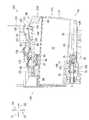
図6(A)に示されるように、IC基板64は、前後方向において、インク供給部34のインク供給口71より後方に位置する。IC基板64、当接面84、及び傾斜面155は、前後方向及び上下方向に沿った仮想平面57(図6(B)参照)と交差しつつ前後方向に沿って並んでいる。IC基板64と傾斜面155との前後方向の間において、傾斜面155の上端が最も上方に位置する。当接面84は、IC基板64の電極65より僅かに上方、且つ傾斜面155の下端と同等、或いは僅かに下方に位置する。[Arrangement of each part in the ink cartridge 30]
As shown in FIG. 6A, the
図6(A)に示されるように、インク供給口71とロック面151との間の前後方向における距離D1は、ロック面151と後面41の上部分41Uとの間の前後方向における距離D2より長い(距離D1>距離D2)。インク供給口71とロック面151の上端との間の上下方向における距離D3は、インク供給口71と当接面84との間の上下方向における距離D4より長い(距離D3>距離D4)。IC基板64の電極65とロック面151との間の前後方向における距離D5は、IC基板64の電極65と当接面84との間の前後方向における距離D6より長い(距離D5>距離D6)。距離D4は、傾斜面155の上端とインク供給口71との間の上下方向における距離D7よりも短い(距離D4<距離D7)。IC基板64の電極65は、前後方向において、インク供給口71より距離D8だけ離れている。 As shown in FIG. 6A, the distance D1 in the front-rear direction between the
[インクカートリッジ30がカートリッジ装着部110へ装着される動作]
以下、インクカートリッジ30がカートリッジ装着部110に装着される過程が説明される。[Operation in which the
Hereinafter, the process of mounting the
図7に示されるように、カートリッジ装着部110に装着される前のインクカートリッジ30において、バルブ77は、パッキング76のインク供給口71を閉じている。これにより、インクバルブ室35からインクカートリッジ30の外部へのインクの流通は遮断されている。また、バルブ97は、大気連通口96を閉じている。これにより、第1貯留室32は、大気開放されていない。 As shown in FIG. 7, in the
インクカートリッジ30は、筐体31の前面40を前方向51を向いており、且つ上面39を上方向54を向いた姿勢、すなわち装着姿勢で、カートリッジ装着部110の開口112を通じてカートリッジケース101へ挿入される。筐体31の後面41の上部分41Uは下部分41Lよりも後方に位置している、すなわち、ユーザの近くに位置しているので、ユーザは、上部分41Uを押しつつインクカートリッジ30をカートリッジ装着部110に対して前方へ挿入する。インクカートリッジ30の下部、カートリッジケース101の下方のガイド溝109に進入した状態となる。 The
図8に示されるように、インクカートリッジ30がカートリッジケース101へ挿入されると、インク供給部34がガイド部105に進入する。また、ロッド125が大気連通口96に進入する。また、光センサ113の発光部と受光部との間に、遮光板67が位置する。 As shown in FIG. 8, when the
インクカートリッジ30の前面40がカートリッジケース101の終面付近まで挿入されると、インクニードル102がインク供給口71へ進入して、バルブ77をコイルバネ78の付勢力に抗してパッキング76から離間させる。これにより、インク供給部34が位置決めされる。インクカートリッジ30には、コイルバネ78の付勢力が後方へ付与される。また、大気連通口96に進入したロッド125は、バルブ97と当接して、コイルバネ98の付勢力に抗してバルブ97を大気連通口96から離間させる。これにより、第1貯留室32が貫通孔46、大気バルブ室36及び大気連通口96を介して大気開放される。 When the
インクカートリッジ30には、圧縮されたコイルバネ78,98により生ずる後方向52への付勢力が作用する。各コイルバネ78,98によりそれぞれ生ずる付勢力の大きさは、バネ定数と自然長から圧縮された距離とにより決まる。コイルバネ98のバネ定数は、コイルバネ78のバネ定数より小さく、また、コイルバネ78が圧縮された距離(バルブ77がインク供給口71から離れた距離)は、コイルバネ98が圧縮された距離(バルブ97が大気連通口96から離れた距離)よりも長い。その結果、インクカートリッジ30がカートリッジ装着部110に装着された状態において、コイルバネ78により生ずる付勢力の大きさは、コイルバネ98により生ずる付勢力の大きさより大きい。 A urging force in the
また、凸部43がロックシャフト145へ到達し、傾斜面155がロックシャフト145に対して摺動する。インクカートリッジ30には、後面41の上部分41Uをユーザが前方へ押すことにより、図7における反時計回りに回転モーメントが加わっている。しかし、傾斜面155とロックシャフト145との当接により、この回転モーメントに反して、インクカートリッジ30は、インクニードル102が挿入されたパッキング76のインク供給口71の中心Cを回動中心として回動する。インクカートリッジ30における中心Cの位置は、インクニードル102の形状とインク供給口71の形状によるが、インクニードル102と筒状のインク供給口34の内面とが接触する部分の中心が仮想的な回動中心である。本実施形態では、インクニードル102における、インク供給口71を画定するパッキング76の内周面が接触している部分の中心を仮想的な回動中心として時計回りに回動する。このときのインクカートリッジ30の姿勢が第2姿勢と称される。 Further, the
なお、筐体31の下面42が前後方向に対して傾斜した傾斜面であることにより、下面42とカートリッジケース101のガイド溝109の底面との間には、前述した回動(時計回りの回動)のためのスペースがある。また、ロッド125の外径よりも大気連通口96の内径が大きいので、ロッド125と大気連通口96との間には、回動(時計回りの回動)のためのスペースが有り、装着状態のインクカートリッジ30において、ロッド125と大気連通口96とは当接しない。すなわち、ロッド125と大気連通口96との間においては、上下方向の位置決めがなされていない。 Since the
インクカートリッジ30がカートリッジケース101に挿入されることにより、接点106の下方にIC基板64が到達する。前述した回動によって、第2姿勢のインクカートリッジ30において、IC基板64の電極65と接点106との間には上下方向において空間が存在する。つまり、電極65と接点106とは離間している。また、位置決め部107の下方に当接面84が到達するが、第2姿勢のインクカートリッジ30において、位置決め部107と当接面84との間には上下方向において空間が存在する。つまり、位置決め部107と当接面84とは離間している。 When the
コイルバネ78の付勢力に抗して、インクカートリッジ30が前方へ挿入されると、凸部43の傾斜面155及び水平面154がロックシャフト145よりカートリッジケース101の終面に近い位置となる。第2姿勢のインクカートリッジ30において、ロック面151は、ロックシャフト145より下方に位置する。 When the
インクカートリッジ30には、後面41の上部分41Uをユーザが前方へ押すことにより、図8における反時計回りに回転モーメントが加わっている。一方、大気バルブ室36に設けられたコイルバネ98の付勢力によって、インクカートリッジ30には時計回りの回転モーメントが生じる。傾斜面155及び水平面154がロックシャフト145と当接しなくなることにより、ユーザの力によって、コイルバネ98の付勢力に抗して、インクカートリッジ30は、インクニードル102が挿入されたパッキング76のインク供給口71の中心Cを回動中心として図8における反時計回りに回動する。そして、当接面84が下方から位置決め部107と当接する。 A rotational moment is applied to the
インクカートリッジ30が図3に示される姿勢にあるときに、ロック面151は、後方へ向かってロックシャフト145と向かい合う。ユーザがインクカートリッジ30を前方へ押し込むことを止めると、インクカートリッジ30は、コイルバネ78の付勢力によって後方へ移動する。ロック面151は後方へ向かってロックシャフト145と向かい合っているので、インクカートリッジ30が後方へ移動すると、ロック面151がロックシャフト145と当接する。これにより、インクカートリッジ30が後方へ移動することが規制される。また、当接面84が下方から位置決め部107と当接することにより、インクカートリッジ30が上方へ移動すること、すなわち中心Cを回動中心として反時計回りに回動することが規制される。その結果、インクカートリッジ30はカートリッジ装着部110内に位置決めされて装着が完了した状態となる。このときのインクカートリッジ30の姿勢が第1姿勢と称される。すなわち、インクカートリッジ30は、中心Cを回動中心として回動することによって、第1姿勢と第2姿勢とに姿勢変化可能である。 When the
なお、第1姿勢において、インクカートリッジ30には、後述される力が作用する。インクカートリッジ30は、自重、IC基板64が接点106から受ける付勢力、及び大気バルブ室36に設けられたコイルバネ98による時計回りの回転モーメント、によって、第1姿勢から第2姿勢へ姿勢変化する方向、すなわち中心Cを回動中心として下方に移動しようとする力が作用する。一方、インクバルブ室35のコイルバネ78によって生じる後方向52への付勢力がロック面151に働くことによって、インクカートリッジ30には、反時計回りの回転モーメントが生じ、中心Cを回動中心として上方に移動しようとする力が生じる。また、当接面84と位置決め部107とが当接しており、当接面84がインクカートリッジ30に働く上方向54の力の成分をうけることにより、インクカートリッジ30が上下方向に対して位置決めされている。 In the first posture, a force described later acts on the
第1姿勢において、ロックシャフト145は、ロック面151の下端から前後方向に延びる面156とは上下方向に離間しているので、ロックシャフト145はインクカートリッジ30の上下方向に位置決めに関与していない。したがって、インクカートリッジ30は、カートリッジ装着部110においてカートリッジケース101とは別体に設けられたロックシャフト145ではなく、カートリッジケース101と一体に設けられ、ロックシャフト145よりも接点106に近い位置に配置された位置決め部107において上下方向の位置決めがなされている。 In the first posture, the
図3に示されるように、第1姿勢のインクカートリッジ30において、ロック面151の上端は、中心Cを中心とし、かつロックシャフト145を通過する仮想円弧58より外方に位置する。また、ロック面151の下端は、仮想円弧58の内方に位置する。第1姿勢のインクカートリッジ30は、インク供給口71とインクニードル102との接触位置、及びロック面151とロックシャフト145との当接位置において位置決めされた状態で、コイルバネ78の後方向52への付勢力を受ける。これにより、インクカートリッジ30には、前方且つ上方へ向かうモーメントが生じる。このモーメントは、インクカートリッジ30を中心Cを回動中心として反時計回りに回動させる力の大きさでもある。 As shown in FIG. 3, in the
第1姿勢のインクカートリッジ30において、IC基板64の各電極65は、接点106を上方へ弾性変形させつつ電気的に接触する。このとき、IC基板64は接点106の弾性変形によって下方へ付勢されるが、前述されたモーメントによって、インクカートリッジ30は、IC基板64が接点106を弾性変形させている状態に保持される。また、インクカートリッジ30は、図8における反時計回りに回動する過程において、中心Cよりも後方且つロック面151よりも前方にあるIC基板64の電極65が下方から上方へ向かって接点106と当接して電気的に導通される。挿抜のときのインクカートリッジ30の移動方向である前後方向と、IC基板64の電極65と接点106とが接離する上下方向とが交差しているので、IC基板64の電極65と接点106とが接触しながら前後方向へ相対移動することが抑制され、電極65の削りカスなどの異物の発生が抑制される。 In the
インクカートリッジ30がカートリッジ装着部110から脱抜されるときには、ユーザは、操作面92を下方へ押す。インクカートリッジ30が第1姿勢である状態において、操作面92は、上方かつ後方を向いているので、インクカートリッジ30がカートリッジ装着部110に対して位置決めされた状態から解除する際に、ユーザが操作面92を操作すると、インクカートリッジ30には下方及び前方へ力が作用する。前方へ作用する力によって、ロック面151がロックシャフト145から離れる。下方へ作用する力によって、インクカートリッジ30が図3における時計回りに回動する。これにより、図8に示されるように、当接面84が位置決め部107から離間し、また、IC基板64の電極65が接点106から離間する。また、ロック面151がロックシャフト145よりも下方に位置する。すなわち、インクカートリッジ30が第1姿勢から第2姿勢へ姿勢変化する。そうすると、コイルバネ78の付勢力によって、インクカートリッジ30はカートリッジ装着部110に対して後方へ移動する。これにより、ユーザは筐体31を挟み持ってインクカートリッジ30をカートリッジ装着部110から取り出すことができる。 When the
[本実施形態の作用効果]
本実施形態によれば、第1姿勢のインクカートリッジ30において、ロック面151がロックシャフト145と当接することによって後方向52に対する位置決めが実現され、且つ、当接面84が位置決め部107と当接することにより上方向54に対する位置決めが実現される。これにより、ロックシャフト145及び位置決め部107に過度の負荷が生じることがなく、その結果、ロックシャフト145及び位置決め部107の変形が抑制されて、インクカートリッジ30の位置決めが安定する。また、ロック面151よりIC基板64に近い当接面84により上方向54に対する位置決めが実現されるので、IC基板64の電極65と接点106との位置決め精度が高まる。[Action and effect of this embodiment]
According to the present embodiment, in the
また、IC基板64と当接面84とは、仮想平面57と交差して前後方向に並んでいるので、IC基板64の電極65と接点106との位置決め精度が安定する。 Further, since the
また、インクカートリッジ30がカートリッジ装着部110に挿入される過程において、凸部43の傾斜面155とロックシャフト145とが当接して、インクカートリッジ30が下方へ移動するので、IC基板64と位置決め部107とが干渉し難い。 Further, in the process of inserting the
また、IC基板64と傾斜面155との前後方向の間において、傾斜面155の上端が最も上方に位置するので、インクカートリッジ30がカートリッジ装着部110に挿入される過程において、インクカートリッジ30の上面39に配置された部材と位置決め部107とが干渉し難い。 Further, since the upper end of the
また、当接面84は、IC基板64の電極65より上方、且つ傾斜面155の上端より下方に位置するので、インクカートリッジ30がカートリッジ装着部110に挿入される過程において、当接面84とロックシャフト145とが干渉し難い。 Further, since the
また、IC基板64は、前後方向において、インク供給口71より後方に位置する。インクカートリッジ30が中心Cを回動中心として回動することによって、IC基板64の電極65の上下方向の位置が変動するが、当接面84と位置決め部107との当接によって、IC基板64の電極65の上方に対する位置決めが精度よく実現される。その結果、IC基板64の配置の自由度が高まる。 Further, the
また、本実施形態においては、IC基板64は、中心Cよりも後方且つロック面151よりも前方にあるので、IC基板64の電極65と接点106とが接触する上下方向と前後方向とが交差する。これにより、IC基板64の電極65と接点106とが接触しながら前後方向へ相対移動することが抑制され、電極65の削りカスなどの異物の発生が抑制される。 Further, in the present embodiment, since the
また、インクバルブ室35のコイルバネ78が、装着状態のインクカートリッジ30を後方向52へ付勢し、ロック面151が、この後方向への付勢力を受けることにより、装着位置においてインクカートリッジ30が安定的に保持される。 Further, the
また、装着状態のインクカートリッジ30に対して、インクバルブ室35のコイルバネ78の付勢力が加わり、更に大気バルブ室36のコイルバネ98の付勢力が加わることにより、インクカートリッジ30がカートリッジから脱抜されるときの後方向52への付勢力が大きくなる。また、コイルバネ98は、インクカートリッジ30の上下方向の寸法の中心よりも上方に配置されており、コイルバネ98による付勢力がコイルバネ78による付勢力よりも小さいので、装着状態のインクカートリッジ30における中心Cを回動中心としたコイルバネ78による回転モーメントが、コイルバネ98による逆向きの回転モーメントより大きくなり、装着状態のインクカートリッジ30がロックされた状態に維持される。また、コイルバネ78とコイルバネ98との上下方向の間の空間が、第1貯留室32として有効活用できる。 Further, the
[変形例]
前述された実施形態では、カートリッジ装着部110において、インクカートリッジ30が中心Cを回動中心として回動することによって、インクカートリッジ30が第1姿勢と第2姿勢とに姿勢変化するが、回動ではなく、インクカートリッジ30が上下方向にスライドすることによって、インクカートリッジ30が第1姿勢と第2姿勢とに姿勢変化するように構成されてもよい。[Modification example]
In the above-described embodiment, when the
また、前述された実施形態では、インクカートリッジ30のインク供給部34に配置されたコイルバネ78によって、カートリッジ装着部110に装着されたインクカートリッジ30が後方向52へ付勢されるが、付勢部材はコイルバネ78に限定されず、コイルバネ78に代えて、例えばインクカートリッジ30の筐体31の前面40から前方へ延びるバネなどの付勢部材が設けられたり、カートリッジケース101の終面から後方へ延びるバネが設けられることによって、カートリッジ装着部110に装着されたインクカートリッジ30が後方向52へ付勢されてもよい。 Further, in the above-described embodiment, the
また、前述された実施形態では、第2付勢部材として大気バルブ室36のコイルバネ98が用いられているが、大気連通口96を開閉するバルブ97の移動のためのコイルバネ98とは独立して、インクカートリッジ30を後方向52へ付勢するためにのみ機能する別のコイルバネなどの付勢部材が設けられてもよい。例えば、インクカートリッジ30において、大気連通口96は段差面95や前面40以外の外面に設けられており、段差面95や上カバー31Uの内部空間において、第1貯留室32の大気開放として機能しない態様でコイルバネが設けられてもよい。 Further, in the above-described embodiment, the
また、前述された実施形態では、インクが印刷流体の一例として説明されているが、例えば、インクに代えて、印刷時にインクに先立って用紙などに吐出される前処理液が印刷流体カートリッジに貯留されていてもよい。また、記録ヘッド21を洗浄するための水が印刷流体カートリッジに貯留されていてもよい。また、トナーなどの流動性を有する粉体が印刷流体であってもよい。 Further, in the above-described embodiment, the ink is described as an example of the printing fluid. For example, instead of the ink, a pretreatment liquid discharged on paper or the like prior to the ink at the time of printing is stored in the printing fluid cartridge. It may have been done. Further, water for cleaning the
10・・・プリンタ(印刷流体消費装置)
21・・・記録ヘッド(印刷流体消費部)
30・・・インクカートリッジ(印刷流体カートリッジ)
34・・・インク供給部(供給部)
39・・・上面
40・・・前面
41・・・後面
42・・・下面
43・・・凸部(第1凸部)
64・・・IC基板(電気的インターフェース)
71・・・インク供給口(供給口)
77・・・バルブ
78・・・コイルバネ(付勢部材)
83・・・凸部(第2凸部)
84・・・当接面
102・・・インクニードル(供給管)
106・・・接点
107・・・位置決め部
145・・・ロック部
151・・・ロック面
155・・・傾斜面(ガイド面)
10 ... Printer (printing fluid consuming device)
21 ... Recording head (printing fluid consumption unit)
30 ... Ink cartridge (printing fluid cartridge)
34 ... Ink supply unit (supply unit)
39 ...
64 ... IC board (electrical interface)
71 ... Ink supply port (supply port)
77 ...
83 ... Convex part (second convex part)
84 ...
106 ・ ・ ・ Contact 107 ・ ・ ・ Positioning
Claims (21)
Translated fromJapanese当該印刷流体カートリッジが上記印刷流体消費装置に挿入される状態において上記第1方向を向く前面と、
上記前面に配置されており、上記印刷流体消費装置に設けられた供給管が挿入され得る供給部と、
当該印刷流体カートリッジが上記印刷流体消費装置に挿入される状態において上方向を向く上面と、
上記上面に配置されており、上記印刷流体消費装置に設けられた接点に接触可能な電気的インターフェースと、
上記上面において上記第2方向へ向けて配置されており、上記印刷流体消費装置に挿入される状態において上記印刷流体消費装置に設けられたロック部に接触するロック面と、
上記上面において上記電気的インターフェースと上記ロック面との間で上方向を向いて配置されており、上記印刷流体消費装置に挿入される状態において上記印刷流体消費装置に設けられた位置決め部に当接する当接面と、を具備しており、
少なくとも上記上面、上記ロック面及び上記当接面は、筐体を構成する同一部材に形成されており、
当該印刷流体カートリッジは、上記印刷流体消費装置に挿入された状態において、上記ロック面が上記第2方向へ向かって上記ロック部に当接し、且つ上記当接面が上記位置決め部に当接した第1姿勢と、上記ロック面が上記ロック部よりも下方に位置し、且つ上記当接面が上記位置決め部から離間した第2姿勢との間で姿勢変化可能である印刷流体カートリッジ。It is attached to the printing fluid consuming device by being inserted into the printing fluid consuming device in the first direction along the horizontal direction against the urging force in the second direction opposite to the first direction. Printing fluid cartridge
When the printing fluid cartridge is inserted into the printing fluid consuming device, the front surface facing the first direction and the front surface facing the first direction,
A supply unit that is arranged on the front surface and into which a supply pipe provided in the printing fluid consuming device can be inserted.
The upper surface facing upward when the printing fluid cartridge is inserted into the printing fluid consuming device, and
An electrical interface that is located on the upper surface and can contact the contacts provided in the printing fluid consuming device,
A lock surface which is arranged on the upper surface in the second direction and comes into contact with a lock portion provided in the printing fluid consuming device in a state of being inserted into the printing fluid consuming device.
It is arranged so as to face upward between the electrical interface and the lock surface on the upper surface, and abuts on the positioning portion provided in the printing fluid consuming device in a state of being inserted into the printing fluid consuming device. It has a contact surface and
At least the upper surface, the lock surface, and the contact surface are formed on the same member constituting the housing.
When the printing fluid cartridge is inserted into the printing fluid consuming device, the lock surface is in contact with the lock portion in the second direction, and the contact surface is in contact with the positioning portion. A printing fluid cartridge whose posture can be changed between one posture and a second posture in which the lock surface is located below the lock portion and the contact surface is separated from the positioning portion.
上記ロック面は、上記第1凸部における上記第1方向の後端に位置しており、
上記第1凸部における上記第1方向の前方に、上記第1方向且つ上方を向いたガイド面が配置されており、
上記ガイド面は、上記電気的インターフェースと上記ロック面との間に位置する請求項1から3のいずれかに記載の印刷流体カートリッジ。It further includes a first convex portion that protrudes upward from the upper surface.
The lock surface is located at the rear end of the first convex portion in the first direction.
A guide surface facing in the first direction and upward is arranged in front of the first convex portion in the first direction.
The printing fluid cartridge according to any one of claims 1 to 3, wherein the guide surface is located between the electrical interface and the lock surface.
上記電気的インターフェース及び上記ガイド面の間において、上記ガイド面の上端が最も上方に位置する部分である請求項4に記載の印刷流体カートリッジ。The electrical interface, the contact surface, and the guide surface are aligned along the first direction.
The printing fluid cartridge according to claim 4, wherein the upper end of the guide surface is located at the uppermost position between the electrical interface and the guide surface.
上記第1付勢部材が、上記第2方向へ向かう付勢力を当該印刷流体カートリッジに付与する請求項1から11のいずれかに記載の印刷流体カートリッジ。The supply unit has a supply port into which the supply pipe is inserted, a valve for opening and closing the supply port, and a first urging member for urging the valve in the first direction.
The printing fluid cartridge according to any one of claims 1 to 11, wherein the first urging member applies an urging force toward the second direction to the printing fluid cartridge.
上記当接部材を上記第1方向へ付勢する第2付勢部材と、を更に有しており、
上記第2付勢部材の第1方向への付勢力は、上記第1付勢部材の第1方向への付勢力より小さい請求項12に記載の印刷流体カートリッジ。An extension extending in the second direction from the printing fluid consuming device at a position above the center of the vertical dimension intersecting the first direction when the printing fluid cartridge is inserted into the printing fluid consuming device. The contact member that comes into contact with the member,
It further has a second urging member that urges the abutting member in the first direction.
The printing fluid cartridge according to claim 12, wherein the urging force of the second urging member in the first direction is smaller than the urging force of the first urging member in the first direction.
上記印刷流体カートリッジを挿入可能な印刷流体消費装置と、を有するシステムであって、
上記印刷流体消費装置は、
印刷流体消費部と、
上記印刷流体カートリッジから上記印刷流体消費部に供給される印刷流体が流通する上記供給管と、
上記第1方向において上記供給管より後方に位置する上記接点と、
上記第1方向において上記接点より後方に位置する上記ロック部と、
上記第1方向において上記接点と上記ロック部との間に位置する上記位置決め部と、を具備するシステム。The printing fluid cartridge according to any one of claims 1 to 13.
A system having a printing fluid consuming device into which the printing fluid cartridge can be inserted.
The above printing fluid consuming device is
Printing fluid consumption department and
The supply pipe through which the printing fluid supplied from the printing fluid cartridge to the printing fluid consumption unit flows,
With the contact located behind the supply pipe in the first direction,
With the lock portion located behind the contact in the first direction,
A system including the positioning portion located between the contact and the lock portion in the first direction.
上記前面と反対の後面と、
上記前面と上記後面との間に設けられた貯留室と、
上記前面と上記後面との間に設けられた上面と、
上記貯留室を挟んで上記上面の反対に設けられた下面と、
上記前面に設けられており、供給口、当該供給口を開閉するバルブ、及び当該バルブを上記供給口へ付勢する付勢部材を有する供給部と、
上記供給部の供給口が外部へ向く第1方向と反対の第2方向を向いており、上記上面に設けられたロック面と、
上方向を向いており、上記上面に設けられた当接面と、
上方向を向いており、上記上面に設けられた電気的インターフェースと、を具備しており、
少なくとも上記上面、上記ロック面及び上記当接面は、筐体を構成する同一部材に形成されており、
上記供給口と上記ロック面との間の上記第1方向における距離D1は、上記ロック面と上記後面との間の上記第1方向における距離D2より長く、
上記供給口と上記ロック面の上端との間の上方向における距離D3は、上記供給口と上記当接面との間の上方向における距離D4より長く、
上記電気的インターフェースと上記ロック面との間の上記第1方向における距離D5は、上記電気的インターフェースと上記当接面との間の上記第1方向における距離D6より長い印刷流体カートリッジ。On the front and
The rear surface opposite to the above front surface,
A storage chamber provided between the front surface and the rear surface,
An upper surface provided between the front surface and the rear surface,
With the lower surface provided opposite to the upper surface across the storage chamber,
A supply port provided on the front surface, a supply port, a valve for opening and closing the supply port, and a supply unit having an urging member for urging the valve to the supply port.
The supply port of the supply unit faces the second direction opposite to the first direction facing the outside, and the lock surface provided on the upper surface thereof
With the contact surface facing upward and provided on the upper surface,
It faces upward and is equipped with an electrical interface provided on the upper surface.
At least the upper surface, the lock surface, and the contact surface are formed on the same member constituting the housing.
The distance D1 in the first direction between the supply port and the lock surface is longer than the distance D2 in the first direction between the lock surface and the rear surface.
The upward distance D3 between the supply port and the upper end of the lock surface is longer than the upward distance D4 between the supply port and the contact surface.
A printing fluid cartridge in which the distance D5 in the first direction between the electrical interface and the lock surface is longer than the distance D6 in the first direction between the electrical interface and the contact surface.
上記第1凸部は、上記電気的インターフェースと上記ロック面との間に位置する傾斜面を有する請求項15又は16に記載の印刷流体カートリッジ。It further includes a first convex portion that protrudes upward from the upper surface.
The printing fluid cartridge according to claim 15 or 16, wherein the first convex portion has an inclined surface located between the electrical interface and the lock surface.
上記電気的インターフェースと上記傾斜面との間において、上記傾斜面の上端が最も上方に位置する部分である請求項17に記載の印刷流体カートリッジ。The electrical interface, the contact surface, and the inclined surface are arranged so as to intersect the virtual plane including the first direction and the upward direction.
The printing fluid cartridge according to claim 17, wherein the upper end of the inclined surface is located at the uppermost position between the electrical interface and the inclined surface.
The printing fluid cartridge according to any one of claims 15 to 20, wherein the electrical interface is arranged at a position separated from the supply unit by a distance D8 in the second direction.
Priority Applications (5)
| Application Number | Priority Date | Filing Date | Title |
|---|---|---|---|
| JP2016255351AJP6930104B2 (en) | 2016-12-28 | 2016-12-28 | Printing fluid cartridges and systems |
| US15/664,348US10328706B2 (en) | 2016-12-28 | 2017-07-31 | Printing-fluid cartridge including contact surface for providing positioning of the printing-fluid cartridge |
| US16/410,507US10668735B2 (en) | 2016-12-28 | 2019-05-13 | Printing-fluid cartridge including contact surface for providing positioning of the printing-fluid cartridge |
| US16/865,553US11529812B2 (en) | 2016-12-28 | 2020-05-04 | Printing-fluid cartridge including contact surface for providing positioning of the printing-fluid cartridge |
| US18/061,654US11884077B2 (en) | 2016-12-28 | 2022-12-05 | Printing-fluid cartridge including contact surface for providing positioning of the printing-fluid cartridge |
Applications Claiming Priority (1)
| Application Number | Priority Date | Filing Date | Title |
|---|---|---|---|
| JP2016255351AJP6930104B2 (en) | 2016-12-28 | 2016-12-28 | Printing fluid cartridges and systems |
Publications (2)
| Publication Number | Publication Date |
|---|---|
| JP2018103565A JP2018103565A (en) | 2018-07-05 |
| JP6930104B2true JP6930104B2 (en) | 2021-09-01 |
Family
ID=62624939
Family Applications (1)
| Application Number | Title | Priority Date | Filing Date |
|---|---|---|---|
| JP2016255351AActiveJP6930104B2 (en) | 2016-12-28 | 2016-12-28 | Printing fluid cartridges and systems |
Country Status (2)
| Country | Link |
|---|---|
| US (4) | US10328706B2 (en) |
| JP (1) | JP6930104B2 (en) |
Families Citing this family (10)
| Publication number | Priority date | Publication date | Assignee | Title |
|---|---|---|---|---|
| JP6930104B2 (en) | 2016-12-28 | 2021-09-01 | ブラザー工業株式会社 | Printing fluid cartridges and systems |
| JP6897098B2 (en) | 2016-12-28 | 2021-06-30 | ブラザー工業株式会社 | Printing fluid cartridges, printing fluid cartridge sets, and systems |
| JP6922219B2 (en) | 2016-12-28 | 2021-08-18 | ブラザー工業株式会社 | Printing fluid cartridges and systems |
| JP7019948B2 (en)* | 2016-12-28 | 2022-02-16 | ブラザー工業株式会社 | Printing fluid cartridges and systems |
| JP7400479B2 (en)* | 2020-01-10 | 2023-12-19 | セイコーエプソン株式会社 | Printing device and carriage |
| SG11202009653SA (en) | 2020-03-31 | 2021-11-29 | Brother Ind Ltd | Liquid cartridge |
| EP3960473B1 (en)* | 2020-08-31 | 2023-08-02 | Brother Kogyo Kabushiki Kaisha | Liquid cartridge |
| JP2024025078A (en)* | 2022-08-10 | 2024-02-26 | キヤノン株式会社 | liquid supply device |
| WO2025028513A1 (en)* | 2023-07-31 | 2025-02-06 | Brother Kogyo Kabushiki Kaisha | Ink container and system |
| EP4556239A1 (en) | 2023-11-14 | 2025-05-21 | Brother Kogyo Kabushiki Kaisha | Ink container and ink supply device |
Family Cites Families (66)
| Publication number | Priority date | Publication date | Assignee | Title |
|---|---|---|---|---|
| US5788388A (en) | 1997-01-21 | 1998-08-04 | Hewlett-Packard Company | Ink jet cartridge with ink level detection |
| US5949459A (en) | 1997-06-04 | 1999-09-07 | Hewlett-Packard Company | Method and apparatus for securing an ink container |
| EP1176020B1 (en) | 2000-07-10 | 2006-09-13 | Canon Kabushiki Kaisha | Liquid discharge recording head cartridge |
| CA2469450C (en) | 2000-10-20 | 2010-02-23 | Seiko Epson Corporation | Ink cartridge for ink jet recording device |
| JP3666491B2 (en) | 2002-03-29 | 2005-06-29 | セイコーエプソン株式会社 | Ink cartridge and recording apparatus |
| JP2007261286A (en) | 2002-03-29 | 2007-10-11 | Seiko Epson Corp | Ink cartridge and recording apparatus |
| JP3919734B2 (en) | 2002-12-06 | 2007-05-30 | 株式会社リコー | Ink cartridge, casing thereof, and image forming apparatus |
| US7021751B2 (en) | 2003-12-30 | 2006-04-04 | Fuji Xerox Co., Ltd. | Robust gasket seal for an inkjet printhead |
| JP4552526B2 (en) | 2004-06-16 | 2010-09-29 | セイコーエプソン株式会社 | Liquid container |
| KR100656513B1 (en) | 2004-07-12 | 2006-12-13 | 삼성전자주식회사 | Inkjet Cartridge Nozzle Tape |
| JP2006159578A (en) | 2004-12-06 | 2006-06-22 | Canon Inc | Ink tank, ink jet recording apparatus, and ink jet recording head recovery processing method |
| JP4539517B2 (en) | 2005-09-29 | 2010-09-08 | ブラザー工業株式会社 | ink cartridge |
| UA91582C2 (en) | 2005-12-26 | 2010-08-10 | Сейко Эпсон Корпорейшн | printing material container and board installed in printing material container |
| JP4144637B2 (en) | 2005-12-26 | 2008-09-03 | セイコーエプソン株式会社 | Printing material container, substrate, printing apparatus, and method for preparing printing material container |
| JP4341688B2 (en) | 2006-04-12 | 2009-10-07 | セイコーエプソン株式会社 | Liquid container |
| JP4125329B2 (en) | 2006-05-19 | 2008-07-30 | キヤノン株式会社 | Liquid storage container and liquid supply system including the container |
| JP2008221803A (en) | 2007-03-15 | 2008-09-25 | Seiko Epson Corp | Liquid container |
| CN101885272B (en) | 2007-03-28 | 2012-01-04 | 兄弟工业株式会社 | Ink cartridge |
| US9067425B2 (en) | 2007-10-12 | 2015-06-30 | Videojet Technologies Inc. | Fluid cartridge for an inkjet printer |
| JP2009132118A (en)* | 2007-11-30 | 2009-06-18 | Brother Ind Ltd | Ink supply device |
| US8534801B2 (en) | 2010-02-19 | 2013-09-17 | Seiko Epson Corporation | Liquid ejecting system and liquid accommodating container |
| JP2011167966A (en) | 2010-02-19 | 2011-09-01 | Seiko Epson Corp | Liquid ejection system, liquid container and liquid ejector |
| EP2397333B1 (en) | 2010-06-17 | 2013-09-25 | Brother Kogyo Kabushiki Kaisha | Ink cartridge and recording apparatus |
| JP5736902B2 (en)* | 2011-03-30 | 2015-06-17 | ブラザー工業株式会社 | Liquid supply system and liquid cartridge |
| JP2013049166A (en) | 2011-08-30 | 2013-03-14 | Brother Industries Ltd | Printing fluid cartridge and recording apparatus |
| JP2013049168A (en) | 2011-08-30 | 2013-03-14 | Brother Industries Ltd | Printing fluid cartridge and recording apparatus |
| JP5974439B2 (en) | 2011-08-30 | 2016-08-23 | ブラザー工業株式会社 | Printing fluid cartridge and recording apparatus |
| US8678553B2 (en) | 2011-09-09 | 2014-03-25 | Brother Kogyo Kabushiki Kaisha | Recording apparatus and printing fluid cartridge set |
| CN103171293B (en) | 2011-12-22 | 2015-07-22 | 兄弟工业株式会社 | Printing fluid cartridge, printing device and utilization of printing fluid cartridge |
| EP2607083B1 (en) | 2011-12-22 | 2014-11-05 | Brother Kogyo Kabushiki Kaisha | Printing fluid cartridge, printing apparatus, and use of printing fluid cartridge |
| EP2607084B1 (en) | 2011-12-22 | 2014-09-24 | Brother Kogyo Kabushiki Kaisha | Printing fluid cartridge and printing apparatus |
| US8678573B2 (en)* | 2011-12-22 | 2014-03-25 | Brother Kogyo Kabushiki Kaisha | Printing fluid cartridge |
| CN105034605B (en) | 2011-12-22 | 2017-08-04 | 兄弟工业株式会社 | Printing Fluid Cartridges, Printing Devices, and Printing Fluid Cartridge Use |
| JP5929169B2 (en) | 2011-12-22 | 2016-06-01 | ブラザー工業株式会社 | Printing fluid cartridge |
| JP2013129178A (en) | 2011-12-22 | 2013-07-04 | Brother Industries Ltd | Printing fluid cartridge |
| JP5929166B2 (en) | 2011-12-22 | 2016-06-01 | ブラザー工業株式会社 | Printing fluid cartridge and regulating member |
| JP6019697B2 (en) | 2012-04-19 | 2016-11-02 | ブラザー工業株式会社 | Printing fluid storage device and printing fluid supply device |
| JP5990995B2 (en) | 2012-04-19 | 2016-09-14 | ブラザー工業株式会社 | Printing fluid cartridge |
| JP6083151B2 (en) | 2012-08-24 | 2017-02-22 | ブラザー工業株式会社 | Printing fluid supply apparatus and printing fluid cartridge |
| JP6142519B2 (en) | 2012-12-14 | 2017-06-07 | ブラザー工業株式会社 | Printing fluid supply apparatus and printing fluid cartridge |
| WO2014111327A1 (en)* | 2013-01-16 | 2014-07-24 | Bayer Material Science Ag | Method for producing a multilayer electromechanical transducer |
| EP2783862B1 (en) | 2013-03-28 | 2019-05-08 | Brother Kogyo Kabushiki Kaisha | Liquid cartridge |
| JP6277641B2 (en) | 2013-09-17 | 2018-02-14 | セイコーエプソン株式会社 | Liquid container |
| CN203567363U (en) | 2013-11-15 | 2014-04-30 | 珠海纳思达企业管理有限公司 | Ink cartridge for inkjet printer |
| CN203666132U (en)* | 2013-12-23 | 2014-06-25 | 珠海纳思达企业管理有限公司 | Ink cartridge |
| JP6330331B2 (en) | 2014-01-14 | 2018-05-30 | セイコーエプソン株式会社 | Liquid container, liquid ejecting system, liquid ejecting apparatus |
| CN204172493U (en) | 2014-08-05 | 2015-02-25 | 珠海纳思达企业管理有限公司 | A kind of inkjet-printing device print cartridge and comprise the inkjet-printing device of this print cartridge |
| JP6398832B2 (en) | 2015-03-27 | 2018-10-03 | ブラザー工業株式会社 | System and consumable cartridge |
| JP6447299B2 (en) | 2015-03-27 | 2019-01-09 | ブラザー工業株式会社 | Liquid cartridge |
| JP6435957B2 (en)* | 2015-03-27 | 2018-12-12 | ブラザー工業株式会社 | Liquid cartridge |
| JP6428433B2 (en) | 2015-03-27 | 2018-11-28 | ブラザー工業株式会社 | Liquid cartridge |
| JP6447300B2 (en) | 2015-03-27 | 2019-01-09 | ブラザー工業株式会社 | Liquid cartridge |
| JP6413881B2 (en)* | 2015-03-27 | 2018-10-31 | ブラザー工業株式会社 | Liquid cartridge |
| US9878552B2 (en) | 2015-06-18 | 2018-01-30 | Brother Kogyo Kabushiki Kaisha | Liquid cartridge provided with connecting channel providing communication between liquid supply chamber and liquid storage chamber |
| EP3112167B1 (en) | 2015-07-01 | 2019-10-23 | Brother Kogyo Kabushiki Kaisha | System in which consumable cartridge is mountable to mounting portion |
| ES2755927T3 (en) | 2015-07-01 | 2020-04-24 | Brother Ind Ltd | Liquid consuming apparatus including a liquid cartridge |
| WO2017006365A1 (en) | 2015-07-07 | 2017-01-12 | Brother Kogyo Kabushiki Kaisha | Liquid cartridge, liquid consuming apparatus, method of inserting liquid cartridge into cartridge mounting portion of liquid consuming apparatus, and use of liquid cartridge |
| CA2990350C (en) | 2015-07-07 | 2020-07-14 | Brother Kogyo Kabushiki Kaisha | Liquid cartridge, liquid consuming apparatus, method of inserting liquid cartridge into cartridge mounting portion of liquid consuming apparatus, and use of liquid cartridge |
| JP6627345B2 (en) | 2015-09-07 | 2020-01-08 | ブラザー工業株式会社 | Liquid cartridge |
| JP6665452B2 (en) | 2015-09-07 | 2020-03-13 | ブラザー工業株式会社 | Liquid cartridge and liquid cartridge manufacturing method |
| JP6708392B2 (en) | 2015-10-28 | 2020-06-10 | キヤノン株式会社 | Recording head |
| CN205439589U (en) | 2015-12-23 | 2016-08-10 | 珠海纳思达企业管理有限公司 | Ink box for ink jet printing equipment |
| JP7019948B2 (en) | 2016-12-28 | 2022-02-16 | ブラザー工業株式会社 | Printing fluid cartridges and systems |
| JP6897098B2 (en) | 2016-12-28 | 2021-06-30 | ブラザー工業株式会社 | Printing fluid cartridges, printing fluid cartridge sets, and systems |
| JP6922219B2 (en)* | 2016-12-28 | 2021-08-18 | ブラザー工業株式会社 | Printing fluid cartridges and systems |
| JP6930104B2 (en)* | 2016-12-28 | 2021-09-01 | ブラザー工業株式会社 | Printing fluid cartridges and systems |
- 2016
- 2016-12-28JPJP2016255351Apatent/JP6930104B2/enactiveActive
- 2017
- 2017-07-31USUS15/664,348patent/US10328706B2/enactiveActive
- 2019
- 2019-05-13USUS16/410,507patent/US10668735B2/enactiveActive
- 2020
- 2020-05-04USUS16/865,553patent/US11529812B2/enactiveActive
- 2022
- 2022-12-05USUS18/061,654patent/US11884077B2/enactiveActive
Also Published As
| Publication number | Publication date |
|---|---|
| US10328706B2 (en) | 2019-06-25 |
| US10668735B2 (en) | 2020-06-02 |
| US20230166517A1 (en) | 2023-06-01 |
| JP2018103565A (en) | 2018-07-05 |
| US11884077B2 (en) | 2024-01-30 |
| US20180178535A1 (en) | 2018-06-28 |
| US20190263129A1 (en) | 2019-08-29 |
| US20200331275A1 (en) | 2020-10-22 |
| US11529812B2 (en) | 2022-12-20 |
Similar Documents
| Publication | Publication Date | Title |
|---|---|---|
| JP6930104B2 (en) | Printing fluid cartridges and systems | |
| JP6922219B2 (en) | Printing fluid cartridges and systems | |
| JP6897098B2 (en) | Printing fluid cartridges, printing fluid cartridge sets, and systems | |
| JP7019948B2 (en) | Printing fluid cartridges and systems | |
| JP6424704B2 (en) | Liquid cartridge | |
| JP6874313B2 (en) | Printing fluid containment device, printing fluid supply device, and adapter | |
| JP6597146B2 (en) | Liquid supply device | |
| JP6870265B2 (en) | Liquid cartridge and liquid consuming device | |
| JP2019064046A (en) | Liquid cartridge and system | |
| JP2013220649A (en) | Printing fluid cartridge | |
| CN207241173U (en) | Fluid cartridge and liquid consuming device | |
| JP6878810B2 (en) | Printing fluid cartridge | |
| JP7000729B2 (en) | Liquid consuming device | |
| JP6961919B2 (en) | Liquid cartridge and liquid consuming device | |
| JP6878812B2 (en) | Liquid cartridge and liquid consuming device | |
| CN111971182B (en) | Liquid cartridge including movable member and system using the same | |
| JP6962114B2 (en) | Liquid cartridges and systems | |
| JP2019064042A (en) | Liquid cartridge and system | |
| JP6962113B2 (en) | Liquid cartridges and systems | |
| JP6961918B2 (en) | Printing fluid containment device, printing fluid supply device, and adapter | |
| JP6380193B2 (en) | Liquid supply device | |
| JP7035417B2 (en) | Liquid cartridges and systems | |
| JP7327538B2 (en) | Printing fluid cartridge and system | |
| JP2019064044A (en) | Liquid cartridge and system | |
| JP2018103564A (en) | Liquid cartridge and image recording apparatus |
Legal Events
| Date | Code | Title | Description |
|---|---|---|---|
| A621 | Written request for application examination | Free format text:JAPANESE INTERMEDIATE CODE: A621 Effective date:20191226 | |
| A977 | Report on retrieval | Free format text:JAPANESE INTERMEDIATE CODE: A971007 Effective date:20201109 | |
| A131 | Notification of reasons for refusal | Free format text:JAPANESE INTERMEDIATE CODE: A131 Effective date:20201215 | |
| A521 | Request for written amendment filed | Free format text:JAPANESE INTERMEDIATE CODE: A523 Effective date:20210210 | |
| TRDD | Decision of grant or rejection written | ||
| A01 | Written decision to grant a patent or to grant a registration (utility model) | Free format text:JAPANESE INTERMEDIATE CODE: A01 Effective date:20210713 | |
| A61 | First payment of annual fees (during grant procedure) | Free format text:JAPANESE INTERMEDIATE CODE: A61 Effective date:20210726 | |
| R150 | Certificate of patent or registration of utility model | Ref document number:6930104 Country of ref document:JP Free format text:JAPANESE INTERMEDIATE CODE: R150 |