JP6927987B2 - Machine for manufacturing substantially cylindrical articles - Google Patents
Machine for manufacturing substantially cylindrical articlesDownload PDFInfo
- Publication number
- JP6927987B2 JP6927987B2JP2018538964AJP2018538964AJP6927987B2JP 6927987 B2JP6927987 B2JP 6927987B2JP 2018538964 AJP2018538964 AJP 2018538964AJP 2018538964 AJP2018538964 AJP 2018538964AJP 6927987 B2JP6927987 B2JP 6927987B2
- Authority
- JP
- Japan
- Prior art keywords
- substantially rigid
- rigid element
- semifield
- machine
- container
- Prior art date
- Legal status (The legal status is an assumption and is not a legal conclusion. Google has not performed a legal analysis and makes no representation as to the accuracy of the status listed.)
- Active
Links
Images


Classifications
- B—PERFORMING OPERATIONS; TRANSPORTING
- B65—CONVEYING; PACKING; STORING; HANDLING THIN OR FILAMENTARY MATERIAL
- B65B—MACHINES, APPARATUS OR DEVICES FOR, OR METHODS OF, PACKAGING ARTICLES OR MATERIALS; UNPACKING
- B65B43/00—Forming, feeding, opening or setting-up containers or receptacles in association with packaging
- B65B43/42—Feeding or positioning bags, boxes, or cartons in the distended, opened, or set-up state; Feeding preformed rigid containers, e.g. tins, capsules, glass tubes, glasses, to the packaging position; Locating containers or receptacles at the filling position; Supporting containers or receptacles during the filling operation
- B65B43/44—Feeding or positioning bags, boxes, or cartons in the distended, opened, or set-up state; Feeding preformed rigid containers, e.g. tins, capsules, glass tubes, glasses, to the packaging position; Locating containers or receptacles at the filling position; Supporting containers or receptacles during the filling operation from supply magazines
- A—HUMAN NECESSITIES
- A24—TOBACCO; CIGARS; CIGARETTES; SIMULATED SMOKING DEVICES; SMOKERS' REQUISITES
- A24F—SMOKERS' REQUISITES; MATCH BOXES; SIMULATED SMOKING DEVICES
- A24F40/00—Electrically operated smoking devices; Component parts thereof; Manufacture thereof; Maintenance or testing thereof; Charging means specially adapted therefor
- A24F40/70—Manufacture
- A—HUMAN NECESSITIES
- A24—TOBACCO; CIGARS; CIGARETTES; SIMULATED SMOKING DEVICES; SMOKERS' REQUISITES
- A24C—MACHINES FOR MAKING CIGARS OR CIGARETTES
- A24C5/00—Making cigarettes; Making tipping materials for, or attaching filters or mouthpieces to, cigars or cigarettes
- A—HUMAN NECESSITIES
- A24—TOBACCO; CIGARS; CIGARETTES; SIMULATED SMOKING DEVICES; SMOKERS' REQUISITES
- A24C—MACHINES FOR MAKING CIGARS OR CIGARETTES
- A24C5/00—Making cigarettes; Making tipping materials for, or attaching filters or mouthpieces to, cigars or cigarettes
- A24C5/02—Cigarette-filling machines
- A24C5/06—Cigarette-filling machines with pressing-chamber
- A—HUMAN NECESSITIES
- A24—TOBACCO; CIGARS; CIGARETTES; SIMULATED SMOKING DEVICES; SMOKERS' REQUISITES
- A24D—CIGARS; CIGARETTES; TOBACCO SMOKE FILTERS; MOUTHPIECES FOR CIGARS OR CIGARETTES; MANUFACTURE OF TOBACCO SMOKE FILTERS OR MOUTHPIECES
- A24D1/00—Cigars; Cigarettes
- A24D1/22—Cigarettes with integrated combustible heat sources, e.g. with carbonaceous heat sources
- A—HUMAN NECESSITIES
- A24—TOBACCO; CIGARS; CIGARETTES; SIMULATED SMOKING DEVICES; SMOKERS' REQUISITES
- A24F—SMOKERS' REQUISITES; MATCH BOXES; SIMULATED SMOKING DEVICES
- A24F40/00—Electrically operated smoking devices; Component parts thereof; Manufacture thereof; Maintenance or testing thereof; Charging means specially adapted therefor
- A24F40/40—Constructional details, e.g. connection of cartridges and battery parts
- B—PERFORMING OPERATIONS; TRANSPORTING
- B65—CONVEYING; PACKING; STORING; HANDLING THIN OR FILAMENTARY MATERIAL
- B65B—MACHINES, APPARATUS OR DEVICES FOR, OR METHODS OF, PACKAGING ARTICLES OR MATERIALS; UNPACKING
- B65B1/00—Packaging fluent solid material, e.g. powders, granular or loose fibrous material, loose masses of small articles, in individual containers or receptacles, e.g. bags, sacks, boxes, cartons, cans, or jars
- B65B1/04—Methods of, or means for, filling the material into the containers or receptacles
- B65B1/10—Methods of, or means for, filling the material into the containers or receptacles by rotary feeders
- B—PERFORMING OPERATIONS; TRANSPORTING
- B65—CONVEYING; PACKING; STORING; HANDLING THIN OR FILAMENTARY MATERIAL
- B65B—MACHINES, APPARATUS OR DEVICES FOR, OR METHODS OF, PACKAGING ARTICLES OR MATERIALS; UNPACKING
- B65B1/00—Packaging fluent solid material, e.g. powders, granular or loose fibrous material, loose masses of small articles, in individual containers or receptacles, e.g. bags, sacks, boxes, cartons, cans, or jars
- B65B1/20—Reducing volume of filled material
- B65B1/24—Reducing volume of filled material by mechanical compression
- B—PERFORMING OPERATIONS; TRANSPORTING
- B65—CONVEYING; PACKING; STORING; HANDLING THIN OR FILAMENTARY MATERIAL
- B65B—MACHINES, APPARATUS OR DEVICES FOR, OR METHODS OF, PACKAGING ARTICLES OR MATERIALS; UNPACKING
- B65B1/00—Packaging fluent solid material, e.g. powders, granular or loose fibrous material, loose masses of small articles, in individual containers or receptacles, e.g. bags, sacks, boxes, cartons, cans, or jars
- B65B1/30—Devices or methods for controlling or determining the quantity or quality or the material fed or filled
- B65B1/36—Devices or methods for controlling or determining the quantity or quality or the material fed or filled by volumetric devices or methods
- B65B1/38—Devices or methods for controlling or determining the quantity or quality or the material fed or filled by volumetric devices or methods by pistons co-operating with measuring chambers
- B65B1/385—Devices or methods for controlling or determining the quantity or quality or the material fed or filled by volumetric devices or methods by pistons co-operating with measuring chambers moving in an endless path
- B—PERFORMING OPERATIONS; TRANSPORTING
- B65—CONVEYING; PACKING; STORING; HANDLING THIN OR FILAMENTARY MATERIAL
- B65B—MACHINES, APPARATUS OR DEVICES FOR, OR METHODS OF, PACKAGING ARTICLES OR MATERIALS; UNPACKING
- B65B43/00—Forming, feeding, opening or setting-up containers or receptacles in association with packaging
- B65B43/42—Feeding or positioning bags, boxes, or cartons in the distended, opened, or set-up state; Feeding preformed rigid containers, e.g. tins, capsules, glass tubes, glasses, to the packaging position; Locating containers or receptacles at the filling position; Supporting containers or receptacles during the filling operation
- B65B43/46—Feeding or positioning bags, boxes, or cartons in the distended, opened, or set-up state; Feeding preformed rigid containers, e.g. tins, capsules, glass tubes, glasses, to the packaging position; Locating containers or receptacles at the filling position; Supporting containers or receptacles during the filling operation using grippers
- B—PERFORMING OPERATIONS; TRANSPORTING
- B65—CONVEYING; PACKING; STORING; HANDLING THIN OR FILAMENTARY MATERIAL
- B65B—MACHINES, APPARATUS OR DEVICES FOR, OR METHODS OF, PACKAGING ARTICLES OR MATERIALS; UNPACKING
- B65B43/00—Forming, feeding, opening or setting-up containers or receptacles in association with packaging
- B65B43/42—Feeding or positioning bags, boxes, or cartons in the distended, opened, or set-up state; Feeding preformed rigid containers, e.g. tins, capsules, glass tubes, glasses, to the packaging position; Locating containers or receptacles at the filling position; Supporting containers or receptacles during the filling operation
- B65B43/50—Feeding or positioning bags, boxes, or cartons in the distended, opened, or set-up state; Feeding preformed rigid containers, e.g. tins, capsules, glass tubes, glasses, to the packaging position; Locating containers or receptacles at the filling position; Supporting containers or receptacles during the filling operation using rotary tables or turrets
- B—PERFORMING OPERATIONS; TRANSPORTING
- B65—CONVEYING; PACKING; STORING; HANDLING THIN OR FILAMENTARY MATERIAL
- B65B—MACHINES, APPARATUS OR DEVICES FOR, OR METHODS OF, PACKAGING ARTICLES OR MATERIALS; UNPACKING
- B65B43/00—Forming, feeding, opening or setting-up containers or receptacles in association with packaging
- B65B43/42—Feeding or positioning bags, boxes, or cartons in the distended, opened, or set-up state; Feeding preformed rigid containers, e.g. tins, capsules, glass tubes, glasses, to the packaging position; Locating containers or receptacles at the filling position; Supporting containers or receptacles during the filling operation
- B65B43/52—Feeding or positioning bags, boxes, or cartons in the distended, opened, or set-up state; Feeding preformed rigid containers, e.g. tins, capsules, glass tubes, glasses, to the packaging position; Locating containers or receptacles at the filling position; Supporting containers or receptacles during the filling operation using roller-ways or endless conveyors
- B—PERFORMING OPERATIONS; TRANSPORTING
- B65—CONVEYING; PACKING; STORING; HANDLING THIN OR FILAMENTARY MATERIAL
- B65B—MACHINES, APPARATUS OR DEVICES FOR, OR METHODS OF, PACKAGING ARTICLES OR MATERIALS; UNPACKING
- B65B43/00—Forming, feeding, opening or setting-up containers or receptacles in association with packaging
- B65B43/42—Feeding or positioning bags, boxes, or cartons in the distended, opened, or set-up state; Feeding preformed rigid containers, e.g. tins, capsules, glass tubes, glasses, to the packaging position; Locating containers or receptacles at the filling position; Supporting containers or receptacles during the filling operation
- B65B43/54—Means for supporting containers or receptacles during the filling operation
- B65B43/56—Means for supporting containers or receptacles during the filling operation movable stepwise to position container or receptacle for the reception of successive increments of contents
- B—PERFORMING OPERATIONS; TRANSPORTING
- B65—CONVEYING; PACKING; STORING; HANDLING THIN OR FILAMENTARY MATERIAL
- B65B—MACHINES, APPARATUS OR DEVICES FOR, OR METHODS OF, PACKAGING ARTICLES OR MATERIALS; UNPACKING
- B65B57/00—Automatic control, checking, warning, or safety devices
- B—PERFORMING OPERATIONS; TRANSPORTING
- B65—CONVEYING; PACKING; STORING; HANDLING THIN OR FILAMENTARY MATERIAL
- B65B—MACHINES, APPARATUS OR DEVICES FOR, OR METHODS OF, PACKAGING ARTICLES OR MATERIALS; UNPACKING
- B65B57/00—Automatic control, checking, warning, or safety devices
- B65B57/10—Automatic control, checking, warning, or safety devices responsive to absence, presence, abnormal feed, or misplacement of articles or materials to be packaged
- B65B57/16—Automatic control, checking, warning, or safety devices responsive to absence, presence, abnormal feed, or misplacement of articles or materials to be packaged and operating to stop, or to control the speed of, the machine as a whole
- B—PERFORMING OPERATIONS; TRANSPORTING
- B65—CONVEYING; PACKING; STORING; HANDLING THIN OR FILAMENTARY MATERIAL
- B65B—MACHINES, APPARATUS OR DEVICES FOR, OR METHODS OF, PACKAGING ARTICLES OR MATERIALS; UNPACKING
- B65B7/00—Closing containers or receptacles after filling
- B65B7/16—Closing semi-rigid or rigid containers or receptacles not deformed by, or not taking-up shape of, contents, e.g. boxes or cartons
- B65B7/28—Closing semi-rigid or rigid containers or receptacles not deformed by, or not taking-up shape of, contents, e.g. boxes or cartons by applying separate preformed closures, e.g. lids, covers
- B65B7/2807—Feeding closures
- B—PERFORMING OPERATIONS; TRANSPORTING
- B65—CONVEYING; PACKING; STORING; HANDLING THIN OR FILAMENTARY MATERIAL
- B65B—MACHINES, APPARATUS OR DEVICES FOR, OR METHODS OF, PACKAGING ARTICLES OR MATERIALS; UNPACKING
- B65B7/00—Closing containers or receptacles after filling
- B65B7/16—Closing semi-rigid or rigid containers or receptacles not deformed by, or not taking-up shape of, contents, e.g. boxes or cartons
- B65B7/28—Closing semi-rigid or rigid containers or receptacles not deformed by, or not taking-up shape of, contents, e.g. boxes or cartons by applying separate preformed closures, e.g. lids, covers
- B65B7/2821—Closing semi-rigid or rigid containers or receptacles not deformed by, or not taking-up shape of, contents, e.g. boxes or cartons by applying separate preformed closures, e.g. lids, covers applying plugs or threadless stoppers
Landscapes
- Engineering & Computer Science (AREA)
- Mechanical Engineering (AREA)
- Microelectronics & Electronic Packaging (AREA)
- Quality & Reliability (AREA)
- Manufacturing Of Cigar And Cigarette Tobacco (AREA)
- Lining Or Joining Of Plastics Or The Like (AREA)
Description
Translated fromJapanese本発明は、タバコ加工産業の略円筒状物品を製造する機械及び方法に関する。 The present invention relates to machines and methods for producing substantially cylindrical articles in the tobacco processing industry.
近年、従来の紙巻タバコとは異なる新たな喫煙物品がいくつか提案されている。この新たな喫煙物品は、紙巻タバコとできるだけ同じ感触を喫煙者に提供するように作成される。 In recent years, some new smoking items have been proposed that are different from conventional cigarettes. This new smoking article is created to provide smokers with the same feel as possible with cigarettes.
特に、発熱要素と風味発生材とを備える喫煙物品が提案されている。使用に際して、発熱要素は風味発生材を加熱し、その結果、吸入中にユーザが吸入する風味物質を放出する。 In particular, smoking articles having a heat generating element and a flavor generating material have been proposed. Upon use, the exothermic element heats the flavor generator and, as a result, releases the flavor material inhaled by the user during inhalation.
このタイプの喫煙物品の一例を特許文献1(米国特許出願公開第2015/0013703号明細書)に記載する。 An example of this type of smoking article is described in Patent Document 1 (US Patent Application Publication No. 2015/0013703).
現在、上記のタイプの物品をはじめとする物品の製造は、ほとんど手動で実施されるか、人力を継続して必要とする旧式の機械によって実施される。その結果、製造には時間がかかり(即ち、生産性が低く)、得られる物品の品質のばらつきが大きい(その上、概ね品質が低い)。 Currently, the manufacture of goods, including those of the above types, is carried out mostly manually or by older machines that require continuous manpower. As a result, the production is time consuming (ie, low productivity) and the quality of the resulting goods varies widely (and generally low quality).
特許文献2(欧州特許出願公開第1228709号明細書)には、多重フィルタを製造する装置が記載される。特に、管状要素が作業ステーションに送られ、このステーションでは、ろ過材が管状要素内に送り込まれることが記載される。回転ユニットが管状要素を回転させる。 Patent Document 2 (European Patent Application Publication No. 1228709) describes an apparatus for manufacturing a multiplex filter. In particular, it is stated that the tubular element is delivered to a work station, where the filter media is delivered into the tubular element. The rotating unit rotates the tubular element.
本発明の目的は、先行技術の欠点を少なくとも部分的に解消することを可能にし、同時に安価で実施が容易な機械及び方法を提供することにある。 An object of the present invention is to provide a machine and method that can at least partially eliminate the shortcomings of the prior art, while at the same time being inexpensive and easy to implement.
本発明によれば、以下に引用する独立請求項と、独立請求項に直接又は間接に従属する請求項のいずれか1項に記載のような機械を提供する。 According to the present invention, there is provided a machine as described in any one of the independent claims cited below and the claims that are directly or indirectly dependent on the independent claims.
ここで本発明を、非限定的な実施形態の例を図示する添付図面を参照して説明する。
図1では、1は、タバコ加工産業の略円筒状物品2(図4及び図5を参照)を製造する機械を全体的に示す。各物品2は、管状体3と、管状体3の一端部5の領域に配置される容器要素4であって、外側を向く端部開口6と、少なくとも1つの側壁7と、端部開口5に対向する底壁8とを有する容器要素4と、一部が容器要素4内にあり、端部開口6を通って容器要素4の外部(特に、端部5を通って管状体3の外部)に突出する端部分10を有する略硬質要素9と、を備える。 In FIG. 1, reference numeral 1 denotes an overall machine for manufacturing a substantially cylindrical article 2 (see FIGS. 4 and 5) in the tobacco processing industry. Each article 2 is a
いくつかの実施形態によれば、容器要素4は、紙材などによって作成される(このため、変形しやすい)。 According to some embodiments, the
特に、底壁8は少なくとも部分的に気体に対して透過性がある。特定の実施形態によれば、底壁8は複数の孔を備える。 In particular, the
有利なことには、容器要素(特に図4及び図5を参照)は、端部開口6周りに延びるカラー11を有する。さらに正確には、カラー11は、側壁7の末端縁をこの側壁自体の上に折り畳むことによって形成される。 Advantageously, the container element (see in particular FIGS. 4 and 5) has a collar 11 extending around the end opening 6. More precisely, the collar 11 is formed by folding the end edge of the
場合によっては、略硬質要素9は、発熱要素(炭素質材、例えば、カーボン)を含む(さらに正確には、発熱要素そのものである)。 In some cases, the substantially
特に、略硬質要素9と容器要素4とは、実質的に一体である。略硬質要素9は、容器要素4と連結した形状に形作られる。 In particular, the substantially
図5は、実施形態の有利な例を図示する。この例では、側壁7は、(別の)変形部12(さらに正確には、容器要素4の内部に向かう折り曲げ部)を有し、略硬質要素9は、変形部12と連結する個別の変形部13(凹部)を有する。変形部12及び13は、略硬質要素9の容器要素4内での位置決めを安定化させるために互いに協働する。 FIG. 5 illustrates an advantageous example of the embodiment. In this example, the
これに加えて、あるいはこれとは別に、略硬質要素9を容器要素4に結び付けるのに接着剤を付加してもよい。 In addition to this, or separately, an adhesive may be added to bond the substantially
各物品2はこのほか、略硬質要素9と底壁8との間の容器要素4内に配置される脆性材料14(さらに正確には、風味発生材)を備える。 Each article 2 also comprises a brittle material 14 (more precisely, a flavor generating material) arranged in a
脆性材料14は典型的には、粉末材料又は粒状材料(特に、粉末)である。例えば、脆性材料14は、タバコ(の粒子、あるいはさらに正確には粉末)を含む(さらに具体的には、同粉末からなる)。 The
代替実施形態によれば、物品2は、(脆性材料14の代わりに)非脆性物質(一体の固体)を含む。 According to an alternative embodiment, article 2 comprises a non-brittle material (instead of the brittle material 14) (integral solid).
特定の非限定例によれば、物品2はこのほか、管状体3の端部5に対向する端部16の領域に配置されるフィルタ15を備える。 According to certain non-limiting examples, the article 2 also includes a
いくつかの非限定的実施形態(図1)によれば、機械1は、容器要素4のための送りアセンブリ17を備える。この送りアセンブリは、容器要素4を垂直に(端部開口を上向きにして)配向させるように構成された、それ自体公知で概略的に示されたタイプの送り格納部18を備える。特に、送りアセンブリは、カラー11と相互作用するガイドの助けを借りて容器要素4を選択して持ち上げる内側コンベヤを備える。この非限定的実施形態によればさらに、機械1は、容器要素を格納部18から作業コンベヤ20(特にドラム)に移送するコンベヤ19を備える。 According to some non-limiting embodiments (FIG. 1), the machine 1 comprises a feed assembly 17 for the
非限定的実施形態によれば、コンベヤ20は、断続的な運動、即ち、コンベヤ20が移動している運動ステップと、コンベヤ20が停止する停止ステップとが周期的に交互に切り替わるようにする非連続的な運動を伴う循環をするように設定される。コンベヤ20は、コンベヤ20自体の周囲に形成され、いくつかのグループに分けられる多数の座部21を備える。特に、各グループは、(コンベヤ20の表面上に多角形を平面に形成するように)直線に沿って配列される多数の座部21を有する。図6に示されるように、各グループは、直線状に配置される14個の座部21を有する。 According to a non-limiting embodiment, the
同一のグループの座部21に含まれる物品2の製造工程の次のステップ(例えば、脆性材料14の装填、略硬質要素9の挿入など)は、並行して実施され、即ち、同一のグループの座部21に含まれた全容器要素4に対して同時に実施される。 The next step in the manufacturing process of the article 2 contained in the
図6に示されるように、格納部18から運ばれコンベヤ19上に整列された空の容器要素4の連続する集合体は、取り出しステーションPSの領域に給送される。この領域では、アーム22が各グループの座部21の数と同数の複数の吸着部材23(例えば、14個の吸着部材23)を有して、コンベヤ20の上方に配置される。 As shown in FIG. 6, a contiguous assembly of
アーム22は、静止上昇位置と下降位置との間で垂直方向に移動可能である。使用に際して、アーム22はコンベヤ19の領域の下降位置に導入され、部材23は容器要素4に入り、容器要素4を(吸引によって)取り出す。この時点で、アーム22は、上昇して座部21上に移動し、次いで、各容器要素4をそれぞれの座部21内に収めるように下降する。続いて、部材23は動作を停止し、上昇してコンベヤ19に戻される。 The
なお、有利なことには、アーム22は、移動手段(それ自体は公知のタイプであって、図示されていない)を備える。この移動手段は、コンテナ要素4をコンベヤ要素19から取り出すのに求められる(図6に示されるような)閉鎖構成から、(互いから離間した)座部21に容器要素4自体を挿入できるようにするのに必要な開放構成に部材23を移動させることによって、部材23同士を互いから離間させるように構成される。 It should be noted that, advantageously, the
この時点で、コンベヤ20は、充填ユニット24の下を移動する積み込みステーションCSを通って取り出しステーションPSから容器要素4を送る。この充填ユニットは、各充填要素4の内部に脆性材料14を挿入するように構成される。 At this point, the
図7に示されているものを参照すると、充填ユニット14は、タバコ粉末を搬送するためのスクリューコンベヤによって作成される固定上部ホッパー25を備える。スクリューコンベヤは、次に下部ホッパー27内に排出されるタバコ粉末のための積み込み口の上端部の領域に設けられて垂直軸を有する外側管状スリーブ26を備える。 With reference to what is shown in FIG. 7, the filling
下部ホッパー27では、円筒状側壁28によって境界を定められた粉末タバコ収集用環状チャンバCが得られる。上部ホッパー25の排出口を、収集チャンバCの領域に配置する。この収集チャンバCの領域は、収集チャンバCの別の領域であって、29及び30を付与され順々に配置される一対のスクレーパ要素が収容される領域と正反対の位置にある領域である。特に、スクレーパ要素29は、粉末材料を粗く削り取るために設けられている。スクレーパ要素29は、円筒状側壁28に接続され、収集チャンバCの幅と等しい寸法の隔壁として作成される。スクレーパ要素29の下流には、粉末材料を微細に削り取るために、さらにスクレーパ要素30が設けられる。スクレーパ要素30は円筒状側壁28に固定され、収集チャンバCの幅より小さい寸法の隔壁として作成される。 The
充填ユニット24は、下部ホッパー27の下に配置され、空の容器要素4に脆性材料14を充填するように作成される複数のディスクを備える。この複数のディスクは共通の垂直回転軸回りに所定の周期で回転する。 The filling
特に、ディスク31は、収集チャンバCの底壁を形成し、円筒状側壁28に接続され、ディスク31自体の周囲に設けられた多数の貫通孔32を備える。この多数の貫通孔は、グループに分けられ、各グループは、一列に配置される多数の孔32であって、各グループの座部21の数に等しい数の孔(即ち、14個の孔32であるが、図示されているのは10個のみである)を有する。 In particular, the
図8及び図9にさらに明瞭に示されているように、ディスク31の下には、さらにディスク33が設けられ、ディスク33自体の周囲に複数のグループに分割された多数の貫通孔34が設けられる。各グループは、一列に配置される多数の孔34であって、各グループの座部21の数に等しい数の孔(即ち、14個の孔34であるが、図示されているのは10個のみである)を有する。 As more clearly shown in FIGS. 8 and 9, a
ディスク33の孔34は、ディスク31の孔32に直接対面しており、その結果、それぞれが一対の伸縮式ガイド35、36によって、一定量の粉末タバコを収容する複数の区画Sを形成する。特に、上部ガイド要素35が、孔32に挿入され、対応する孔34内に収容される下部ガイドの要素36と協働して、粉末タバコを収集する区画Sを形成する。 The
2つのディスク31及び33は、垂直方向に相互に移動可能であり、その結果、相互間の距離が変化し、単一の区画Sの体積が、上部ガイド要素35の肩部38が下部ガイド要素36の上縁39に当接する(2つのディスク31及び33ができるだけ互いに近く配置される)最小体積と、2つのディスク31及び33ができるだけ互いから遠く配置される最大体積との間で変化する。 The two
好適な実施形態によれば、ディスク31は、区画Sの最小体積及び最大体積にそれぞれ対応する両端位置の間で垂直方向に往復移動可能であるのに対し、ディスク33は固定される。 According to a preferred embodiment, the
単一の区画Sの体積(即ち、2つのディスク31及び33の間の相対的な距離)は、容器要素4内に挿入される粉末タバコの重さ(即ち、量)の関数として、物品2を製造する工程の予備工程にて決定される。これとは別に、あるいはこれに加えて、区画Sの体積は、脆性材料14の可能な限り精確な充填が可能となるように(後に説明するように)その後に実施される測定に基づくフィードバックとして変更される。 The volume of a single compartment S (ie, the relative distance between the two
区画Sは、上部ホッパー25から注ぎ込まれたタバコ粉末で充填され、収集チャンバC内に連続して配置された2つのスクレーパ要素29及び30の作用によって、各区画S内に含まれる粉末タバコの量を均一に調整することができる。 The compartment S is filled with tobacco powder poured from the
図8、図9及び図11に示されるように、各区画Sは、ディスク33の下に配置される追加のディスク40によって底部が閉鎖され、微細孔付きプラスチック材から作成され、互いに独立した複数のセクター40*に分割される環状要素として設計される。各セクター40*は、セクター40*自体の内縁近傍に形成された多数の貫通孔41を備える。この多数の貫通孔41は、一列に配置され、各グループの座部21の数に等しい数(即ち、14個の孔41)である。 As shown in FIGS. 8, 9 and 11, each compartment S is made of microperforated plastic material with the bottom closed by an
各セクター40*は、両端位置の間、(図8aに示される)前方位置と(図8bに示される)後方位置との間で往復移動可能である。前方位置では、セクター40*は、それぞれの区画Sの底壁を形成し、外縁を円筒状側壁28及び2つのディスク31及び33の外面と重なるように配置する。 Each
セクター40*は、前方位置から、後退し、充填ユニット24の外部に向かって、後方位置に配置されるまで突出するように制御される。後方位置では、各孔41はそれぞれの孔34に向かい合う位置に配置される。言い換えれば、各孔41は、それぞれの区画Sの領域に正確に配置される。 The
最終的に、図10に示されるように、充填ユニット24は、ディスク40の下に配置されて多数の貫通開口43を備える追加のディスク42を具備する。この多数の貫通孔は、ディスク42自体の外縁近傍に形成され、複数のグループに分割される。各グループは、一列に並べられる多数の開口43であって、各グループの座部21の数に等しい数の開口(即ち、14個の開口43)を有する。 Finally, as shown in FIG. 10, the filling
特に、開口43は、セクター40*を介在させて、それぞれの区画Sの領域に正確に配置される。開口43は、下向きの案内空洞44を形成するU字状環状縁によって境界を定められる。案内空洞44は、容器要素4の上縁のためのガイドとして作用して、脆性材料14(特に、粉末タバコ)の溢れ及び堆積を大幅に減少させる。 In particular, the openings 43 are precisely located in the regions of the respective compartments S with the
図7に示されるように、収集チャンバC内のスクレーパ要素30に隣接して、複数の押し込み要素46を備えるアーム45が収容されている。特に、アーム45は、一列に並んで配置される多数の押し込み要素であって、各グループの座部21の数に等しい数の押し込み要素(即ち、14個の押し込み要素46)を有する。アーム45は、上方位置と下方操作位置との間で垂直方向に往復移動可能であり、下方操作位置では、各押し込み要素46は、少なくとも部分的にそれぞれの区画S内に挿入され、同区画から取り出される。 As shown in FIG. 7, an
積み込みステーションCSの領域ではこのほか、ディスク42の下に配置され、複数の支持要素48を備える(図10に部分的に図示される)アーム47を設ける。特に、アーム47は、一列に配置される多数の支持要素48であって、各グループの座部21の数に等しい数の支持要素(即ち、14個の支持要素48)を有する。 In addition, in the area of the loading station CS, an arm 47 (partially illustrated in FIG. 10), which is arranged below the
積み込みステーションCSでは、ディスク31及び32、40及び42は、各区画Sをそれぞれの押し込み要素46及びそれぞれの支持要素48の領域に配置することができる位置に停止する。アーム47は、休止位置と上方操作位置との間で垂直方向に往復移動可能である。 In the loading station CS, the
タバコ粉末の充填された容器要素5の積み込みステーションCSの領域では、以下のステップが連続して実施される。
‐コンベヤ20は、ディスク42の下、アーム47の上にある積み込みステーションCSの領域にて空の容器要素4を搬送する。
‐座部21の顎部は、それぞれがそれぞれの支持要素48によって支持される容器要素4を解放する。
‐アーム47は、休止位置から上方操作位置に移動するように作動し、このようにして、各支持要素48がそれぞれの容器要素4を、上縁が関連する案内空洞44に挿入されるまで持ち上げる。
‐セクター40*は、各孔41がそれぞれの孔34及びそれぞれの区画Sの領域に配置されるように、前方位置から後方位置に移動して、その結果、区画Sに包含される粉末タバコが容器要素4に向かって下方に移動することができる。
‐アーム45は、各押し込み要素46がそれぞれの区画S内に挿入されるように上方位置から下方操作位置に降下する。アーム45の下方操作位置への移動は、容器要素4内のタバコ粉末の下方への移動に押し込み要素46が付随する第1のステップと、容器要素4が充填された時点で、案内空洞44から外れた容器要素4の下方への移動にアーム45が付随する第2のステップとに分割される。
‐アーム45は、下方操作位置に到達した時点で、再度逆戻りし、空間Sから出て上方位置に戻るまで移動する。
‐アーム45の移動と同時に、アーム47はこのほか、上方操作位置から休止位置に移動するように作動する。休止位置では、アーム47は、タバコ粉末を包含する容器要素4を、容器要素を保持する顎部を備えるそれぞれの座部21に搬送する。
‐セクター40*は、区画Sと開口43との間の連通を防止するために、後方位置から前方に、前方位置に再度配置されるまで移動する。
‐充填ユニット24のディスク31及び33、40及び42は最終的に、タバコを包含する容器要素4をコンベヤ20が前方に搬送する間、回転するようになる。In the area of the loading station CS of the container element 5 filled with tobacco powder, the following steps are carried out in succession.
-
-The jaws of the
-The
-
-The
-When the
-At the same time as the movement of the
The-
-The
なお、タバコ粉末を包含する容器要素5の下方への移動に付随するアーム45の移動によってこのほか、タバコ粉末の集合体を所望の濃度が得られるまでわずかに圧縮することができる。 In addition, the movement of the
ここまで機械1に関して記載されたことは、特定の非限定的実施形態に関するものと考えるべきである。 What has been described with respect to Machine 1 so far should be considered as relating to a particular non-limiting embodiment.
本発明の第1の態様によれば、タバコ加工産業の略円筒状物品2(図4及び図5を参照)を製造するための機械1(特に、図1〜図3)が設けられる。各物品2は上記の通りである。 According to the first aspect of the present invention, a machine 1 (particularly, FIGS. 1 to 3) for manufacturing a substantially cylindrical article 2 (see FIGS. 4 and 5) of the tobacco processing industry is provided. Each article 2 is as described above.
機械1は、コンベヤ20と、挿入アセンブリ49と、コントラスト手段51とを備える。コンベヤ20は、挿入ステーションIS(例えば、図12を参照)を介して所与の経路P1に沿って脆性材料14を包含する少なくとも1つの容器要素4を移動させるように構成され、容器要素4を収容するための少なくとも1つの座部21を備える。挿入アセンブリ49は、それぞれの略硬質要素9を容器要素4内に挿入するように構成され、挿入ステーションISの領域内に配置され、端部開口6を介して略硬質要素9を下方に押し込んで容器要素4内に部分的に挿入するための押し込みユニット50を備える。コントラスト手段51は、押し込みユニット50の押圧の反対側の底壁に抵抗を加える。このようにして、略硬質要素の挿入を、再現可能に、迅速かつ精確な方法で、容器要素4を損傷するリスクが低い状態で得ることができる。 The machine 1 includes a
特に、座部21は、側壁7と接触するように構成された少なくとも1つの内側側面を備える。なお、このようにして、(好適な実施形態によれば、軽量かつ比較的壊れやすい材料で作成される)側壁7が安定化されるため、容器要素4を損傷するリスクをさらに大幅に低減する。 In particular, the
有利には、コントラスト手段51は、底壁8と接触するために上方に移動するように構成される少なくとも1つの移動ヘッド52を備える。 Advantageously, the contrast means 51 includes at least one moving
この配置はこのほか、容器要素4を損傷するリスクを低減することを可能にする(この場合、特に、底壁8は、運搬中及びシート21への挿入中に低い応力を受ける)。 This arrangement also makes it possible to reduce the risk of damaging the container element 4 (in this case, in particular, the
有利には、コンベヤ20は、少なくとも2つの顎部53を備え、そのうちの少なくとも一方が他方に対して可動であり、その結果、顎部53は、開いた構成(例えば、図6)から、座部21を形成する閉じた構成(例えば、図12)に移動可能である。特に、2つの顎部53の少なくとも一方は、他方に対して回転可能(さらに正確には旋回可能)である。さらに正確には、両方の顎部53は移動可能(旋回可能)である。 Advantageously, the
さらに詳細には、座部21は容器要素4を収容するように設計される。この容器要素のカラーは、カラーがカラー自体の表面(上部)と接触するように、座部21の外側に(直接に)配置される。 More specifically, the
なお、上記のような顎部53は、(単独か、移動ヘッドと組み合わせて)容器要素4に対してとりわけ柔らかく接触することができる。 It should be noted that the
いくつかの実施形態によれば、機械1は、顎部53を移動させる(既知のタイプのものであり、図示されていない)アクチュエータ(例えば、電動モーター又は中央運動源に接続される運動学的機構)を含む。 According to some embodiments, the machine 1 is a kinematics connected to an actuator (eg, an electric motor or central kinematic source) that moves the jaw 53 (of a known type and not shown). Mechanism) is included.
有利なことには、座部21は(移動ヘッド52の通過を可能にするように)開いて下方に移動する。有利なことには、座部21は(押し込みユニット50の押し込み具50*が通過できるように)開いて上方に移動する。 Advantageously, the
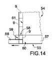
実施形態のいくつかの例によれば、機械1はこのほか、略硬質要素9を挿入ステーションISに給送するように構成される送りアセンブリ54(例えば、図12及び図13)を備える。この送りアセンブリは、押し込みユニット50が略硬質要素9を端部開口6を通して押す方向に対して横方向に、略硬質要素9を移動させる移送装置55を備える(特に、図13〜図15を参照)。 According to some examples of embodiments, the machine 1 also includes a feed assembly 54 (eg, FIGS. 12 and 13) configured to feed a substantially
有利なことには、移送装置55は、2つの半体シェル56及び57を備える。この2つの半体シェルは、互いの間に略硬質要素9を収容するために、互いに結合されるように構成される。特に、(既知のタイプのものであり、図示されていない)作動手段(例えば、電動モータ、あるいは中央運動源に接続された運動機構)を、第1及び第2の半体シェルを(個別にも組み合わせても)動かすために設ける。 Advantageously, the
さらに正確には、作動手段は、(半体シェル57とは独立して、さらに詳細には、半体シェル57を実質的に静止状態に保持することによって)半体シェル56を挿入ステーションISを通して移動させ、収集ステーションRSから半体シェル56及び57を共に移動させるように構成される。収集ステーションの領域では、略硬質要素9が半体シェル57に提供され、挿入ステーションISに提供される。 More precisely, the actuating means inserts the
有利なことには、結合構成の半体シェル56及び57は、(少なくとも部分的に)上方を向く通路開口58を有する。押し込みユニット50の押し込み具50*は、通路開口58を通過して略硬質要素9と接触し、この略硬質要素を容器要素4に向けて押すように構成される。 Advantageously, the
特に、通路開口58は、半体シェル57(のみ)に形成される。さらに具体的には、半体シェル57は、略硬質要素9の第1の(上側の)部分を取り囲むように構成される上部59であって、略硬質要素9の通過を可能にするように構成されて上方を向いた開口58を備える上部と、半体シェル56と協働して略硬質要素9の第2の(下側の)部分を包囲するようにするように構成される下部60と、を備える。 In particular, the
いくつかの実施形態によれば、送りアセンブリ54は、略硬質要素9を移送装置55、特に、収集ステーションRSに搬送する少なくとも1つの送りチャネル61を備える。 According to some embodiments, the
特に、チャネル61は、硬質要素9を長手方向及び下方向(特に、実質的に垂直方向)に送るように構成される。 In particular, the
さらに正確には、送りチャネル61は、略硬質要素9が重力の利点を利用して送りチャネル61自体の内部を移動するように、下方に向けられている(上から下に延びている)。 More precisely, the
特定の実施形態によれば、送りチャネル61は、一方が他方の上に配置された略硬質要素9の列を収容するように構成される。 According to certain embodiments, the
特に、送りチャネル61は、通路開口58を通して略硬質要素を運ぶように構成される。 In particular, the
いくつかの実施形態によれば、送りアセンブリ54は、順次配置された複数の送りチャネル61と、分配装置62とを備える。特に、分配装置62は、略硬質要素9をさまざまなチャネル61に運ぶように構成される。 According to some embodiments, the
有利なことには、分配装置62は、移送装置55と反対側の送りチャネル61の(上側の)端部64に略硬質要素9を送るように構成される変形可能なダクト63を備える。 Advantageously, the
特に、機械1(さらに具体的には、送りアセンブリ54)は、(既知のタイプであり、図示されていない)作動手段(例えば、電動モータ、あるいは中央運動源に接続された運動機構)をさらに備える。この作動手段は、変形可能なダクト63の一方の排出端部65を、連続する送りチャネル61に平行な方向に移動させる。このようにして、排出端部65は、略硬質要素9を実際に必要とするチャネル61の領域内に持ち込むことができ、このチャネル61はこうして補充される。 In particular, the machine 1 (more specifically, the feed assembly 54) further provides actuating means (eg, an electric motor, or a motion mechanism connected to a central motion source) (a known type, not shown). Be prepared. This actuating means moves one
有利なことには、追加の作動手段は、排出端部65をこのほか、連続する送りチャネル61に平行な方向を横断する方向に移動させるように構成される。このように、(実際的に、端部64の前方及び/又は後方に移動させることによって)略硬質要素を必要としないチャネル61を送ることを避けることができる。 Advantageously, the additional actuating means is configured to move the
有利なことには、連続する送りチャネル61に対してオフセットして(さらに平行に)支持面が設けられる。この支持面の上では排出端部65が摺動して、略硬質要素9が支持面から出るのを回避することができる。 Advantageously, the support surface is provided offset (more parallel) with respect to the
いくつかの実施形態では、機械1(さらに具体的には、送りアセンブリ54)は、送りチャネル61内の略硬質要素9の存在を検出する(既知のタイプであり、図示されていない)センサと、このようなセンサによって検出されたものの関数として別の作動手段を作動させるように設計される(既知のタイプであり、図示されていない)制御部と、を備える。例えば、センサは、チャンネル61に包含される略硬質要素9の列が最小レベルを下回るか、最大レベルを上回るときに信号を出力してもよい。 In some embodiments, the machine 1 (more specifically, the feed assembly 54) is with a sensor (a known type, not shown) that detects the presence of a substantially
略硬質要素9の給送は、上記のように、とりわけ効率的かつ精確である。 The feeding of the substantially
いくつかの実施形態によれば、送りアセンブリ54は、略硬質要素を分配装置62に運ぶ(それ自体が既知のタイプの)少なくとも1つの格納部54*及びコンベヤ62*を備える。有利なことには、格納部54*には、必要に応じて方向づけられた硬質要素9を選択して取り出すことができる選択・収集システムが設けられる。 According to some embodiments, the
本発明の第2の態様によれば、タバコ加工産業の略円筒状物品2(図4及び図5を参照)を製造する機械1が設けられる(特に図1〜図3)。各物品2は上記の通りである。 According to the second aspect of the present invention, a machine 1 for manufacturing a substantially cylindrical article 2 (see FIGS. 4 and 5) in the tobacco processing industry is provided (particularly FIGS. 1 to 3). Each article 2 is as described above.
機械1はコンベヤ66と挿入アセンブリ70とを備える。コンベヤ66は、略硬質要素9と容器要素4とを備える(特に、両要素から構成される)少なくとも1つの複合要素67を、挿入ステーションIS2を通って所与の経路P2に沿って移動させるように構成される。このコンベヤは、複合要素67を収容するように構成される少なくとも1つの座部68であって、略硬質要素9をブロックして挿入ステーションIS2の領域にて容器要素4を少なくとも部分的に自由にするように構成されるブロッキング装置69を備える少なくとも1つの座部を備える。挿入アセンブリ70は、複合要素67を少なくとも部分的に、対応する管状体3に挿入するように構成される。この挿入アセンブリは、挿入ステーションIS2の領域に配置され、(特に、容器要素4の少なくとも一部が管状体3に挿入されるように)複合要素67と管状体3のうちの一方を他方に向けて押すための押し込みユニット71を備える。 Machine 1 includes a
さらに正確には、押し込みユニット71は、管状体3を複合要素67の方に押すように構成される。 More precisely, the
(図示のものなどの)いくつかの実施形態によれば、コンベヤは、複合要素67の一群を挿入ステーションIS2に断続的に(即ち、運動ステップの周期的な交代を提供する非連続的な動きで)送るように構成され、その結果、静止ステップ中、押し込みユニット71は、複数の複合要素67をそれぞれの管状体3に挿入する。 According to some embodiments (such as those shown), the conveyor intermittently (ie, provides periodic alternation of motion steps) a group of
場合によっては、押し込みユニット71は、それぞれが1つの管状体3を同時に押し込むように構成される複数の押し込み具を備える。 In some cases, the push-in
特に、コンベヤ66は、複合要素67を(複合要素67の長手方向の延伸に対して)横方向に移動させるように構成される。さらに正確には、コンベヤ66は、複合要素67を水平方向に移動させるように構成される。 In particular, the
特に、コンベヤ66は、溝72を横方向に移動させるように構成される。 In particular, the
図面に示される例によれば、座部68は、座部68自体に配置される容器要素4の(略硬質要素9が係合する)端部開口6が横方向に(特に実質的に水平方向に)方向付けられるように構成される。 According to the example shown in the drawing, the
(図示の例のように)場合によっては、コンベヤ66は、管状体3を収容するように設計される少なくとも1つの溝72を備える。座部68は、溝72の開放端に(溝が長手方向に延伸する方向にて)向き合うように配置される。特に、座部68は、(複合要素67が座部68に配置されたときに)複合要素67が横切るように構成される開口73であって、溝72の方を向いて同溝に面している開口73を備える。換言すると、複合要素67は、(コンベヤ66によって搬送されるとき)座部72の開口73を通って延び、その開口は溝72の方を向いている。 In some cases (as in the illustrated example), the
有利なことには、挿入アセンブリ70は、管状体3を収容するように設計される第2の溝74を備える平板73(図18〜図20)と、(既知のタイプであり、図示されていない)作動手段(例えば、中央運動源に接続される電気モータ又は運動機構)とを備える。この作動手段は、平板73自体がコンベヤ66から分離している休止位置(図18)と、溝74が溝72と対向する(溝72の上面上に載置される)ように平板73がコンベヤ66に連結されて、管状チャネルを共に形成し、この管状チャネルは管状体3が管状チャネル内部を(長手方向に)摺動できるような形状に形作られる操作位置(図19及び図20)との間で、平板73を移動させる。 Advantageously, the
平板73は、管状体3を適切に配向させた状態に保持し、それにより管状体3自体の中に複合要素67をさらに正確に挿入するのに役立つ。 The
有利なことには、ブロッキング装置69は、略硬質要素9の少なくとも一部をブロックするように構成されるブロッキング要素75と、容器要素4を少なくとも部分的に取り囲むブロッキング要素76と、(既知のタイプであり、図示されていない)作動手段(例えば、中央運動源に接続される電気モータ又は運動機構)とを備える。この作動手段は、容器要素4の少なくとも一部が突出部から自由になり、管状体3に挿入されるように、ブロッキング要素76をブロッキング要素75とは独立に(さらに正確には、ブロッキング要素75に対して)移動させる。 Advantageously, the blocking
有利なことには、座部68は、カラー11がブロッキング要素75の外面と接触して配置されるように構成される。 Advantageously, the
いくつかの実施形態によれば、機械1は送りアセンブリ77を備える。この送りアセンブリは、コンベヤ66、特にそれぞれの溝72に管状体3を送るように構成され、特に、管状体3をそれぞれの溝72に長手方向(及び水平方向)に押すための押し込みアセンブリ78を備える。 According to some embodiments, the machine 1 comprises a feed assembly 77. This feed assembly is configured to feed the
場合によっては、送りアセンブリ77は、管状体3の集合体が実質的に水平方向に保持される格納部79を備える。特に、押し込みアセンブリ78は、管状体3を格納部79(さらに正確には格納部79の下部出口)から移動させるように構成される。 In some cases, the feed assembly 77 includes a
有利なことには、コンベヤ66は、挿入ステーションIS2の領域内で実質的に同時に複合要素67の一群を運ぶように、断続的な動きで動くように構成される。挿入アセンブリ70は、複数の複合要素67それぞれを少なくとも部分的に、それぞれの管状体3に挿入するように構成される。 Advantageously, the
場合によっては、図示されているように、機械1はこのほか、コンベヤ66から物品2のグループを取り出し、このようなグループを別の出力コンベヤに送るように構成される排出アーム66*を備える。 In some cases, as shown, the machine 1 also includes a
有利なことには、本発明の第1の態様の機械1のために示されたものは、本発明の第2の態様の機械1に対して示されているものと組み合わされる。 Advantageously, what is shown for the machine 1 of the first aspect of the invention is combined with what is shown for the machine 1 of the second aspect of the invention.
本発明の第3の態様によれば、タバコ加工産業の略円筒状物品2(図4及び図5を参照)を製造する方法が提供される。各物品2は上記の通りである。 According to a third aspect of the present invention, there is provided a method for producing a substantially cylindrical article 2 (see FIGS. 4 and 5) in the tobacco processing industry. Each article 2 is as described above.
この方法は、積み込みステーションCS及び積み込みステーションCSの下流に配置される第1の挿入ステーションISを介して、所与の経路P1に沿って、上方を向いた端部開口6を有する容器要素4を搬送する搬送ステップと、積み込みステップであって、このステップ中に積み込みステーションCSの領域にて、脆性材料14が容器要素4内に挿入される積み込みステップと、積み込みステップの後に実施され、略硬質要素9が下方に移動することによって(少なくとも)部分的に容器要素4内に挿入されて複合要素67を得る第1の挿入ステップと、第1の挿入ステップの後に実施される第2の挿入ステップであって、このステップ中に(タバコ加工産業の略円筒状物品2を得るために)複合要素67が管状体3内に少なくとも部分的に挿入されるステップと、を含む。 This method provides a
いくつかの実施形態によれば、この方法は、第1の挿入ステップの後に実施される回転ステップであって、このステップ中に、複合要素67が(略硬質要素が係合する)端部開口6が本質的に横方向(具体的には水平方向)に面するように回転させられるステップを含む。第2の挿入ステップ中に、複合要素67と管状体3のうち少なくとも一方が、複合要素67を少なくとも部分的に管状体3に挿入するように実質的に水平方向に移動する。 According to some embodiments, the method is a rotation step performed after the first insertion step, during which the
有利なことには、この方法は、第1の挿入ステップの後であって回転ステップの前に実施される移送ステップを含む。この移送ステップ中に、複合要素67は、その上端部及び下端部にて、2つのブロッキング要素80及び81が(互いに向かって)反対方向に(トングのような動きで)移動して前記略硬質要素9に接触し、(複合要素67を取り出すことによって)それぞれが前記容器要素4に接触して、これにより、前記略硬質要素9が係合する前記端部開口6を上方を向いた状態に保持することによって固定され、取り出しユニット82*によって横方向に取り出される。この取り出しユニットは、それ自体を中心に(実質的に水平軸回りに)回転させられる。 Advantageously, the method comprises a transfer step performed after the first insertion step and before the rotation step. During this transfer step, the
特に、移送ステップは、経路P1と経路P2との間に配置された移送ステーションTSの領域で実施され、複合要素67が経路P1から経路P2に運ばれる。さらに正確には、移送は、(取り出しユニット82*を備える)移送装置82によって達成される。 In particular, the transfer step is carried out in the region of the transfer station TS located between the route P1 and the route P2, and the
いくつかの実施形態によれば、移送ステップの間に、取り出しユニット82*は、(それ自体回り、具体的には実質的に水平軸回りに回転した後に)実質的に水平なコンベヤ66上に複合要素67を載置する。 According to some embodiments, during the transfer step, the
いくつかの実施形態によれば、この方法は、結合要素67が所与の経路P2に沿って挿入ステーションIS2を通って移動する運搬ステップを含む。この挿入ステーションの領域では、第2の挿入ステップが実施される。具体的には、運搬ステップの間に、複合要素67は、横方向(具体的には水平方向)に配向された(略硬質要素9が係合する)端部開口6を有する。 According to some embodiments, the method comprises a transport step in which the
有利なことには、搬送ステップ(と、特に移送ステップと運搬ステップ)の間に、容器要素4(と、それぞれの複合要素67)の一群が、断続的な運動(即ち、運動ステップと静止ステップとの周期的な交代を提供する非連続的な動き)によってまとまって搬送され、その結果、静止ステップの間には、(複数の)略硬質要素9それぞれが、この一群のそれぞれの容器要素4に実質的に同時に挿入される。 Advantageously, during the transfer step (and especially the transfer step and the transfer step), a group of container elements 4 (and their respective composite elements 67) are moved in an intermittent motion (ie, motion step and stationary step). Discontinuous movements that provide a periodic alternation with) are transported together so that during the stationary step, each of the (plurality) substantially
これに加えて、あるいはこれとは別に、移送ステップと運搬ステップの間に、一群の複合要素67が断続的な運動(即ち、運動ステップと静止ステップとの周期的な交代を提供する非連続的な動き)で共に搬送され、その結果、静止ステップでは、この一群の複合要素67はそれぞれ、(実質的に同時に)それぞれの管状体3に挿入される。 In addition to or separately from this, between the transfer step and the transport step, a group of
有利なことには、この方法は、積み込みステップの後であって第1の挿入ステップの前に実施される第1の制御ステップを含む。この制御ステップの間には、容器要素4内の脆性材料14の量が推定(検出)される。特に、搬送ステップの間には、容器要素4は、積み込みステーションCSと挿入ステーションISとの間に(経路P1に沿って)配置される制御ステーションVSを通って搬送される。この制御ステーションの領域では、第1の制御が実施される。具体的には、第1の制御ステップの間には、容器要素4内の脆性材料14のレベルが(レーザプローブ83(図7)によって)検出される。 Advantageously, the method comprises a first control step performed after the loading step and before the first insertion step. During this control step, the amount of
有利なことには、この方法は、第1の挿入ステップの後であって(特に、第1の制御ステップにて)第2の挿入ステップの前に実施される除去ステップを含む。この除去ステップの間、複合要素67は所与の経路P1から除去される。具体的には、除去ステップは、挿入ステーションISの下流(さらに正確には移送ステーションTSの上流)に経路P1に沿って配置される除去ステーションWSで実施される。 Advantageously, the method comprises a removal step performed after the first insertion step (particularly in the first control step) and before the second insertion step. During this removal step, the
このようにして、第1の制御ステップの後に欠陥があるとわかった複合要素67を排除することが可能である。これとは別に、あるいはこれに加えて、(さらに精確な)サンプル制御をさらに実施するために、除去された複合要素67(又は除去された複数の複合要素67)を計量することが可能である。このような場合には、除去された複合要素67(又は除去された複数の複合要素67)を計量することができる。 In this way, it is possible to eliminate the
有利なことには、この方法は、略硬質要素9を容器要素4に挿入するために加えられる力が検出される第2の制御ステップを含む。このようにして、複合要素67が適正な特徴を有することが確認される。 Advantageously, the method includes a second control step in which the force applied to insert the substantially
この点に関して、検出された力が過剰である場合、このことは、略硬質要素9が誤って側壁7と接触している(この側壁を変形させていると推定される)という事実によると考えられる。測定された強度が低い場合、このことは、容器要素4の断面が略硬質要素9に対して柔らかすぎることによるものと思われる。 In this regard, if the detected force is excessive, this is believed to be due to the fact that the substantially
これに加えて、あるいはこれとは別に、この方法は、第3の制御ステップを含む。この制御ステップでは、(略円筒状物品2が適正な特徴を有することを確認するために)複合要素67を管状体3に挿入するために加えられる力が検出される。 In addition to or separately from this, the method comprises a third control step. In this control step, the force applied to insert the
いくつかの実施形態によれば、この方法は、接着剤を側壁7の内側に塗布する塗布ステップを含む。この塗布ステップは、第1の挿入ステップの前であり、好ましくは積み込みステップの後に実施される。この塗布ステップは、積み込みステーションCSと挿入ステーションISとの間の経路P1に沿って配置される塗布ステーションの領域で有利に実施される。特に、接着剤は噴霧器によって(滴にして)塗布される。 According to some embodiments, the method comprises a coating step of applying the adhesive to the inside of the
特に、この方法は、本発明の第1及び/又は第2の態様による機械1によって実施される。 In particular, this method is carried out by the machine 1 according to the first and / or second aspect of the present invention.
Claims (13)
Translated fromJapanese各物品(2)は、
管状体(3)と、
前記管状体(3)の第1の端部(5)の領域に配置される容器要素(4)であって、外方を向いた端部開口(6)と、少なくとも1つの側壁(7)と、前記端部開口(6)に対向する底壁(8)と、を有する容器要素(4)と、
前記容器要素(4)内に部分的に収容される略硬質要素(9)であって、前記端部開口(6)を通って前記容器要素(4)の外部に突出する端部分(10)を有する略硬質要素(9)と、
前記容器要素(4)内の前記略硬質要素(9)と前記底壁(8)との間に配置される脆性材料(14)と、を具備し、
前記機械(1)は、
前記脆性材料(14)を包含する少なくとも1つの容器要素(4)を、所与の経路(P1)に沿って、挿入ステーション(IS)を通って移動させるように構成されるコンベヤ(20)であって、前記容器要素(4)を収容し、前記側壁(7)に接触するように構成される少なくとも1つの内側側面を備える少なくとも1つの座部(21)を具備するコンベヤ(20)と、
前記略硬質要素(9)それぞれを前記容器要素(4)に挿入するように構成され、前記挿入ステーション(IS)の領域に配置される挿入アセンブリ(49)であって、前記略硬質要素(9)を、前記端部開口(6)を通して下方に押し込み、部分的に前記容器要素(4)内に挿入する押し込みユニット(50)を具備する挿入アセンブリ(49)と、
前記押し込みユニット(50)によって加えられる押圧に対向する前記底壁(8)に抵抗を加えるコントラスト手段(51)と、
前記略硬質要素(9)を前記挿入ステーション(IS)に送るように構成される送りアセンブリ(54)であって、前記押し込みユニット(50)が前記略硬質要素(9)を前記端部開口(6)を通して押し込む方向に対して横方向に前記略硬質要素(9)を移動させる移送装置(55)を具備する、送りアセンブリ(54)と、を具備し、
前記移送装置(55)は、
第1及び第2の半体シェル(56、57)であって、第1の半体シェルと第2の半体シェルとの間に前記略硬質要素(9)を収容するために互いに連結するように構成される第1及び第2の半体シェル(56、57)と、
前記第1及び第2の半体シェル(56、57)を移動させる作動手段と、
を具備する、
機械。A machine that manufactures substantially cylindrical articles (2) in the tobacco processing industry.
Each article (2) is
Tubular body (3) and
A container element (4) disposed in the region of the first end (5) of the tubular body (3), with an outward facing end opening (6) and at least one side wall (7). And a container element (4) having a bottom wall (8) facing the end opening (6).
An end portion (10) that is a substantially rigid element (9) partially housed in the container element (4) and projects to the outside of the container element (4) through the end opening (6). With a substantially hard element (9) having
A brittle material (14) arranged between the substantially hard element (9) in the container element (4) and the bottom wall (8) is provided.
The machine (1)
On a conveyor (20) configured to move at least one container element (4) containing the brittle material (14) through an insertion station (IS) along a given path (P1). A conveyor (20) comprising at least one seat (21) accommodating the container element (4) and having at least one inner side surface configured to contact the side wall (7).
An insertion assembly (49) configured to insert each of the substantially rigid elements (9) into the container element (4) and located in the region of the insertion station (IS), the substantially rigid element (9). ) Is pushed downward through the end opening (6) and partially inserted into the container element (4) with an insertion assembly (49) comprising a pushing unit (50).
Contrast means (51) that applies resistance to the bottom wall (8) facing the pressure applied by the pushing unit (50).
A feed assembly (54) configured to feed the substantially rigid element (9) to the insertion station (IS), wherein the push-in unit (50) opens the substantially rigid element (9) to the end opening ( A feed assembly (54) comprising a transfer device (55) for moving the substantially rigid element (9) laterally with respect to a direction of pushing through 6).
The transfer device (55) is
First and second semifield shells (56, 57) that are connected to each other to accommodate the substantially rigid element (9) between the first and second semifield shells. The first and second semifield shells (56, 57) configured as
Activating means for moving the first and second semifield shells (56, 57) and
Equipped with
machine.
前記押し込みユニット(50)は、前記通路開口(58)を通過して前記略硬質要素(9)に接触し、該略硬質要素(9)を前記容器要素(4)の方に押すように構成される少なくとも1つの押し込み具(50*)を具備する、
請求項1〜4のいずれか1項に記載の機械。The first and second semifield shells (56, 57) have aisle openings (58) that, when in an articulated configuration, are at least partially upward facing.
The pushing unit (50) is configured to pass through the passage opening (58), come into contact with the substantially hard element (9), and push the substantially hard element (9) toward the container element (4). Equipped with at least one pusher (50 *) to be
The machine according to any one of claims 1 to 4.
前記第1の半体シェル(56)を前記挿入ステーション(IS)を通して移動させるとともに、
収集ステーション(RS)であって、該収集ステーション(RS)の領域では前記略硬質要素(9)が前記第2の半体シェル(57)に送られる収集ステーション(RS)から前記挿入ステーション(IS)に、前記第1及び第2の半体シェル(56、57)を共に移動させるように構成される、請求項1〜5のいずれか1項に記載の機械。The operating means
While moving the first semifield shell (56) through the insertion station (IS),
The collection station (RS), in the region of the collection station (RS), the insertion station (IS) from the collection station (RS) where the substantially rigid element (9) is sent to the second semifield shell (57). ), The machine according to any one of claims 1 to 5, wherein the first and second semifield shells (56, 57) are configured to move together.
前記略硬質要素(9)の第1の部分を取り囲むように構成される上側部分(59)であって、上方を向いて前記略硬質要素(9)が通過できるように構成される通路開口(58)を備える、上側部分(59)と、
前記第1の半体シェル(56)と協働して前記略硬質要素(9)の第2の部分を取り囲むように構成される下側部分(60)と、
を具備する、請求項1〜6のいずれか1項に記載の機械。The second semifield shell (57)
A passage opening (59) that is an upper portion (59) configured to surround the first portion of the substantially rigid element (9) and is configured to allow the substantially rigid element (9) to pass upward. 58) with an upper portion (59) and
A lower portion (60) configured to surround a second portion of the substantially rigid element (9) in cooperation with the first semifield shell (56).
The machine according to any one of claims 1 to 6, wherein the machine comprises.
前記略硬質要素(9)を前記移送装置(55)に、搬送するように構成される少なくとも1つの送りチャネル(61)を具備する、
請求項1〜7のいずれか1項に記載の機械。The feed assembly (54)
The substantially rigid element (9) to said transfer device (55)comprises at least one feed channel (61) configured to carry,
The machine according to any one of claims 1 to 7.
前記略硬質要素(9)の第1の部分を取り囲むように構成される上側部分(59)であって、上方を向いて前記略硬質要素(9)が通過できるように構成される通路開口(58)を備える、上側部分(59)を具備し、
前記送りチャネル(61)は前記略硬質要素(9)を前記通路開口(58)を通して運ぶように構成される、請求項8又は9に記載の機械。The second semifield shell (57)
A passage opening (59) that is an upper portion (59) configured to surround the first portion of the substantially rigid element (9) and is configured to allow the substantially rigid element (9) to pass upward. 58), including an upper portion (59),
The machine according to claim 8 or 9, wherein the feed channel (61) isconfigured to carry the substantially rigid element (9) through the passage opening (58).
順々に配置される複数の送りチャネル(61)と、
前記略硬質要素(9)を、前記移送装置(55)に対向する前記送りチャネル(61)の端部(64)に送るように構成される変形可能なダクト(63)を具備する、分配装置(62)と、
を具備する、請求項8〜10のいずれか1項に記載の機械。The feed assembly (54)
A plurality of feed channels (61) arranged in order, and
Distributor comprising a deformable duct (63) configured to feed the substantially rigid element (9) to the end (64) of the feed channel (61) facing the transfer device (55). (62) and
The machine according to any one of claims 8 to 10.
前記別の作動手段を、前記センサによって検出されたものの関数として作動させるように設計される制御部と、
を具備する、請求項12に記載の機械。A sensor configured to detect the presence of a substantially rigid element (9) in the feed channel (61).
A control unit designed to operate the other operating means as a function of what is detected by the sensor.
12. The machine according to claim 12.
Applications Claiming Priority (3)
| Application Number | Priority Date | Filing Date | Title |
|---|---|---|---|
| IT102015000062991 | 2015-10-19 | ||
| ITUB2015A004735AITUB20154735A1 (en) | 2015-10-19 | 2015-10-19 | Welder device and method for its realization. |
| PCT/IB2016/056276WO2017068506A1 (en) | 2015-10-19 | 2016-10-19 | Machine for producing substantially cylindrical articles |
Publications (2)
| Publication Number | Publication Date |
|---|---|
| JP2018537121A JP2018537121A (en) | 2018-12-20 |
| JP6927987B2true JP6927987B2 (en) | 2021-09-01 |
Family
ID=55273373
Family Applications (1)
| Application Number | Title | Priority Date | Filing Date |
|---|---|---|---|
| JP2018538964AActiveJP6927987B2 (en) | 2015-10-19 | 2016-10-19 | Machine for manufacturing substantially cylindrical articles |
Country Status (8)
| Country | Link |
|---|---|
| US (1) | US10856574B2 (en) |
| EP (1) | EP3364799B1 (en) |
| JP (1) | JP6927987B2 (en) |
| KR (1) | KR102680630B1 (en) |
| CN (1) | CN108135279B (en) |
| IT (1) | ITUB20154735A1 (en) |
| PL (1) | PL3364799T3 (en) |
| WO (1) | WO2017068506A1 (en) |
Families Citing this family (13)
| Publication number | Priority date | Publication date | Assignee | Title |
|---|---|---|---|---|
| ITUB20154987A1 (en)* | 2015-10-19 | 2017-04-19 | Gd Spa | Welder device and method for its realization. |
| USD861751S1 (en)* | 2018-05-15 | 2019-10-01 | Mb2 Cup Development Llc | Cartridge maker |
| EP3300848B1 (en) | 2016-09-28 | 2019-10-23 | Braun GmbH | Electric shaver |
| EP3784576B1 (en) | 2018-04-26 | 2024-08-21 | Mpi, Llc | Folded package |
| US11918032B2 (en) | 2018-04-26 | 2024-03-05 | Mpi, Llc | Packer station of a packaging apparatus and system |
| AU2019301719A1 (en)* | 2018-07-11 | 2021-02-18 | Flat Planet Limited | Flower cartridge for herb delivery |
| CN113498320B (en)* | 2019-01-21 | 2024-12-27 | 吉第联合股份公司 | Machine and method for producing electronic cigarette cartridges |
| PL3975760T3 (en)* | 2019-05-31 | 2023-06-19 | G.D S.P.A. | Machine and method for making a sub-unit of a smoking article |
| IT201900007680A1 (en)* | 2019-05-31 | 2020-12-01 | Gd Spa | MACHINE AND METHOD FOR MAKING A SUB-UNIT OF A SMOKING ARTICLE |
| IT201900007689A1 (en)* | 2019-05-31 | 2020-12-01 | Gd Spa | MACHINE AND METHOD FOR MAKING A SUB-UNIT OF A SMOKING ARTICLE |
| EP4070672A4 (en)* | 2019-10-11 | 2024-07-24 | Ccobato (Shenzhen) Technology Co., Ltd | Heat-not-burn vapor generating body and preparation method therefor, tobacco product and vapor generating body |
| US11794438B2 (en) | 2020-12-07 | 2023-10-24 | Mark W. Holderman | Packaging apparatus, system, and method for forming filled cones |
| US12004557B2 (en) | 2020-12-07 | 2024-06-11 | Mpi, Llc | Packaging apparatus, system, and method for forming filled cones |
Family Cites Families (15)
| Publication number | Priority date | Publication date | Assignee | Title |
|---|---|---|---|---|
| DE3626734A1 (en)* | 1986-08-07 | 1988-02-11 | Bosch Gmbh Robert | MACHINE FOR SORTING, FILLING AND SEALING HOLLOW BODIES |
| DE69120970T2 (en)* | 1991-03-28 | 1997-02-20 | Leiras Oy, Turku | DEVICE FOR PRODUCING SUBCUTANEOUS CAPSULES |
| US6336896B1 (en) | 1999-11-12 | 2002-01-08 | Chieh-Hsueh Hsu | Automatic filter tip attaching machine |
| DE10105010A1 (en)* | 2001-01-29 | 2002-09-12 | Hauni Maschinenbau Ag | Method and device for producing multiple filters |
| ITBO20040238A1 (en) | 2004-04-22 | 2004-07-22 | Gd Spa | CIGARETTE FILTER AND RELATED METHOD OF REALIZATION |
| WO2006048767A1 (en) | 2004-11-05 | 2006-05-11 | Philip Morris Products S.A. | Vertical filter filling machine and process |
| EP2338360B1 (en) | 2008-09-17 | 2018-04-18 | Yonglin Liang | Alexipharmic cigarette filter material and its preparation |
| DE102009041318A1 (en)* | 2009-09-15 | 2011-03-31 | Hauni Maschinenbau Ag | Inserting filter segments in filter strands |
| WO2013146951A2 (en) | 2012-03-30 | 2013-10-03 | 日本たばこ産業株式会社 | Carbon heat source and flavour inhalation tool |
| PL2844090T3 (en)* | 2012-04-30 | 2018-01-31 | Philip Morris Products Sa | Two-part multi-component combiner |
| ITBO20120584A1 (en)* | 2012-10-26 | 2014-04-27 | Gd Spa | MACHINE FOR REALIZING CIGARETTES WITH ADJUSTABLE VENTILATION. |
| WO2014136719A1 (en) | 2013-03-05 | 2014-09-12 | 日本たばこ産業株式会社 | Combustion heat source, flavor inhaler, and method for producing combustion heat source |
| WO2014142079A1 (en)* | 2013-03-11 | 2014-09-18 | 日本たばこ産業株式会社 | Combustion heat source and flavour inhaler |
| TWI663923B (en) | 2013-05-21 | 2019-07-01 | 菲利浦莫里斯製品股份有限公司 | Method for combining segments of a smoking article, combiner for combining such segments and use of such method and combiner in the manufacture of smoking articles |
| PL3119678T3 (en)* | 2014-03-21 | 2019-03-29 | G.D Societa' Per Azioni | Machine and method for producing electronic-cigarette cartridges |
- 2015
- 2015-10-19ITITUB2015A004735Apatent/ITUB20154735A1/enunknown
- 2016
- 2016-10-19WOPCT/IB2016/056276patent/WO2017068506A1/ennot_activeCeased
- 2016-10-19PLPL16812824Tpatent/PL3364799T3/enunknown
- 2016-10-19EPEP16812824.7Apatent/EP3364799B1/enactiveActive
- 2016-10-19USUS15/767,678patent/US10856574B2/enactiveActive
- 2016-10-19CNCN201680061033.4Apatent/CN108135279B/enactiveActive
- 2016-10-19JPJP2018538964Apatent/JP6927987B2/enactiveActive
- 2016-10-19KRKR1020187014293Apatent/KR102680630B1/enactiveActive
Also Published As
| Publication number | Publication date |
|---|---|
| KR102680630B1 (en) | 2024-07-03 |
| EP3364799A1 (en) | 2018-08-29 |
| EP3364799B1 (en) | 2021-10-13 |
| CN108135279A (en) | 2018-06-08 |
| KR20180069897A (en) | 2018-06-25 |
| ITUB20154735A1 (en) | 2017-04-19 |
| CN108135279B (en) | 2021-01-22 |
| JP2018537121A (en) | 2018-12-20 |
| US20180303159A1 (en) | 2018-10-25 |
| WO2017068506A1 (en) | 2017-04-27 |
| US10856574B2 (en) | 2020-12-08 |
| PL3364799T3 (en) | 2021-12-20 |
Similar Documents
| Publication | Publication Date | Title |
|---|---|---|
| JP6927987B2 (en) | Machine for manufacturing substantially cylindrical articles | |
| JP7021090B2 (en) | Machines that manufacture substantially cylindrical articles | |
| JP6823059B2 (en) | Machines for manufacturing substantially cylindrical articles | |
| JP6845229B2 (en) | E-cigarette cartridge manufacturing machine and equipment for manufacturing packages containing e-cigarette cartridges | |
| KR102602581B1 (en) | Machine for manufacturing cartridges for electronic cigarettes | |
| JP7200227B2 (en) | Filling unit for manufacturing machines for the production of disposable cartridges for e-cigarettes | |
| JP2020532472A (en) | Manufacturing machine for the production of disposable cartridges for e-cigarettes | |
| JP7157145B2 (en) | Manufacturing machine for the production of disposable cartridges for electronic cigarettes | |
| JP7189205B2 (en) | Manufacturing machine for the production of disposable cartridges for electronic cigarettes | |
| WO2017187502A1 (en) | Rod product production device | |
| IT201600072773A1 (en) | Machine for manufacturing industry articles |
Legal Events
| Date | Code | Title | Description |
|---|---|---|---|
| A621 | Written request for application examination | Free format text:JAPANESE INTERMEDIATE CODE: A621 Effective date:20190717 | |
| A977 | Report on retrieval | Free format text:JAPANESE INTERMEDIATE CODE: A971007 Effective date:20200828 | |
| A131 | Notification of reasons for refusal | Free format text:JAPANESE INTERMEDIATE CODE: A131 Effective date:20200915 | |
| A601 | Written request for extension of time | Free format text:JAPANESE INTERMEDIATE CODE: A601 Effective date:20201214 | |
| A521 | Request for written amendment filed | Free format text:JAPANESE INTERMEDIATE CODE: A523 Effective date:20210108 | |
| A131 | Notification of reasons for refusal | Free format text:JAPANESE INTERMEDIATE CODE: A131 Effective date:20210302 | |
| A601 | Written request for extension of time | Free format text:JAPANESE INTERMEDIATE CODE: A601 Effective date:20210602 | |
| A521 | Request for written amendment filed | Free format text:JAPANESE INTERMEDIATE CODE: A523 Effective date:20210611 | |
| TRDD | Decision of grant or rejection written | ||
| A01 | Written decision to grant a patent or to grant a registration (utility model) | Free format text:JAPANESE INTERMEDIATE CODE: A01 Effective date:20210706 | |
| A61 | First payment of annual fees (during grant procedure) | Free format text:JAPANESE INTERMEDIATE CODE: A61 Effective date:20210805 | |
| R150 | Certificate of patent or registration of utility model | Ref document number:6927987 Country of ref document:JP Free format text:JAPANESE INTERMEDIATE CODE: R150 | |
| R250 | Receipt of annual fees | Free format text:JAPANESE INTERMEDIATE CODE: R250 | |
| R250 | Receipt of annual fees | Free format text:JAPANESE INTERMEDIATE CODE: R250 |