JP6927986B2 - OCT imaging catheter with delay compensation - Google Patents
OCT imaging catheter with delay compensationDownload PDFInfo
- Publication number
- JP6927986B2 JP6927986B2JP2018538773AJP2018538773AJP6927986B2JP 6927986 B2JP6927986 B2JP 6927986B2JP 2018538773 AJP2018538773 AJP 2018538773AJP 2018538773 AJP2018538773 AJP 2018538773AJP 6927986 B2JP6927986 B2JP 6927986B2
- Authority
- JP
- Japan
- Prior art keywords
- catheter
- sensor
- current
- imaging sensor
- image
- Prior art date
- Legal status (The legal status is an assumption and is not a legal conclusion. Google has not performed a legal analysis and makes no representation as to the accuracy of the status listed.)
- Active
Links
- 238000003384imaging methodMethods0.000titleclaimsdescription60
- 238000012014optical coherence tomographyMethods0.000claimsdescription28
- 230000003111delayed effectEffects0.000claimsdescription5
- 238000010586diagramMethods0.000claimsdescription4
- 238000001514detection methodMethods0.000claimsdescription3
- 238000000034methodMethods0.000description34
- 238000012937correctionMethods0.000description18
- 210000004204blood vesselAnatomy0.000description7
- 238000005259measurementMethods0.000description7
- 239000013307optical fiberSubstances0.000description6
- 238000000429assemblyMethods0.000description5
- 230000000712assemblyEffects0.000description5
- 230000008859changeEffects0.000description5
- 230000008901benefitEffects0.000description4
- 230000001934delayEffects0.000description4
- 230000003902lesionEffects0.000description4
- 238000012986modificationMethods0.000description4
- 230000004048modificationEffects0.000description4
- 238000003702image correctionMethods0.000description3
- 230000006378damageEffects0.000description2
- 238000012544monitoring processMethods0.000description2
- 230000004044responseEffects0.000description2
- 208000037803restenosisDiseases0.000description2
- 201000001320AtherosclerosisDiseases0.000description1
- 208000027418Wounds and injuryDiseases0.000description1
- 230000006978adaptationEffects0.000description1
- 238000002399angioplastyMethods0.000description1
- 238000013459approachMethods0.000description1
- 238000005452bendingMethods0.000description1
- 230000008602contractionEffects0.000description1
- 201000010099diseaseDiseases0.000description1
- 208000037265diseases, disorders, signs and symptomsDiseases0.000description1
- 238000006073displacement reactionMethods0.000description1
- 230000000694effectsEffects0.000description1
- 230000007717exclusionEffects0.000description1
- 239000000835fiberSubstances0.000description1
- 230000035876healingEffects0.000description1
- 208000014674injuryDiseases0.000description1
- 238000002608intravascular ultrasoundMethods0.000description1
- 230000009191jumpingEffects0.000description1
- 230000007246mechanismEffects0.000description1
- 239000000203mixtureSubstances0.000description1
- 238000012907on board imagingMethods0.000description1
- 230000008569processEffects0.000description1
- 238000012545processingMethods0.000description1
- 238000006467substitution reactionMethods0.000description1
- 238000012360testing methodMethods0.000description1
- 238000012546transferMethods0.000description1
- 238000012800visualizationMethods0.000description1
Images


Classifications
- A—HUMAN NECESSITIES
- A61—MEDICAL OR VETERINARY SCIENCE; HYGIENE
- A61B—DIAGNOSIS; SURGERY; IDENTIFICATION
- A61B5/00—Measuring for diagnostic purposes; Identification of persons
- A61B5/74—Details of notification to user or communication with user or patient; User input means
- A61B5/742—Details of notification to user or communication with user or patient; User input means using visual displays
- A61B5/7445—Display arrangements, e.g. multiple display units
- A—HUMAN NECESSITIES
- A61—MEDICAL OR VETERINARY SCIENCE; HYGIENE
- A61B—DIAGNOSIS; SURGERY; IDENTIFICATION
- A61B17/00—Surgical instruments, devices or methods
- A61B17/32—Surgical cutting instruments
- A61B17/3205—Excision instruments
- A61B17/3207—Atherectomy devices working by cutting or abrading; Similar devices specially adapted for non-vascular obstructions
- A61B17/320758—Atherectomy devices working by cutting or abrading; Similar devices specially adapted for non-vascular obstructions with a rotating cutting instrument, e.g. motor driven
- A—HUMAN NECESSITIES
- A61—MEDICAL OR VETERINARY SCIENCE; HYGIENE
- A61B—DIAGNOSIS; SURGERY; IDENTIFICATION
- A61B17/00—Surgical instruments, devices or methods
- A—HUMAN NECESSITIES
- A61—MEDICAL OR VETERINARY SCIENCE; HYGIENE
- A61B—DIAGNOSIS; SURGERY; IDENTIFICATION
- A61B17/00—Surgical instruments, devices or methods
- A61B17/22—Implements for squeezing-off ulcers or the like on inner organs of the body; Implements for scraping-out cavities of body organs, e.g. bones; for invasive removal or destruction of calculus using mechanical vibrations; for removing obstructions in blood vessels, not otherwise provided for
- A—HUMAN NECESSITIES
- A61—MEDICAL OR VETERINARY SCIENCE; HYGIENE
- A61B—DIAGNOSIS; SURGERY; IDENTIFICATION
- A61B17/00—Surgical instruments, devices or methods
- A61B17/32—Surgical cutting instruments
- A61B17/3205—Excision instruments
- A61B17/3207—Atherectomy devices working by cutting or abrading; Similar devices specially adapted for non-vascular obstructions
- A61B17/320783—Atherectomy devices working by cutting or abrading; Similar devices specially adapted for non-vascular obstructions through side-hole, e.g. sliding or rotating cutter inside catheter
- A—HUMAN NECESSITIES
- A61—MEDICAL OR VETERINARY SCIENCE; HYGIENE
- A61B—DIAGNOSIS; SURGERY; IDENTIFICATION
- A61B5/00—Measuring for diagnostic purposes; Identification of persons
- A61B5/0033—Features or image-related aspects of imaging apparatus, e.g. for MRI, optical tomography or impedance tomography apparatus; Arrangements of imaging apparatus in a room
- A61B5/0036—Features or image-related aspects of imaging apparatus, e.g. for MRI, optical tomography or impedance tomography apparatus; Arrangements of imaging apparatus in a room including treatment, e.g., using an implantable medical device, ablating, ventilating
- A—HUMAN NECESSITIES
- A61—MEDICAL OR VETERINARY SCIENCE; HYGIENE
- A61B—DIAGNOSIS; SURGERY; IDENTIFICATION
- A61B5/00—Measuring for diagnostic purposes; Identification of persons
- A61B5/0033—Features or image-related aspects of imaging apparatus, e.g. for MRI, optical tomography or impedance tomography apparatus; Arrangements of imaging apparatus in a room
- A61B5/004—Features or image-related aspects of imaging apparatus, e.g. for MRI, optical tomography or impedance tomography apparatus; Arrangements of imaging apparatus in a room adapted for image acquisition of a particular organ or body part
- A61B5/0044—Features or image-related aspects of imaging apparatus, e.g. for MRI, optical tomography or impedance tomography apparatus; Arrangements of imaging apparatus in a room adapted for image acquisition of a particular organ or body part for the heart
- A—HUMAN NECESSITIES
- A61—MEDICAL OR VETERINARY SCIENCE; HYGIENE
- A61B—DIAGNOSIS; SURGERY; IDENTIFICATION
- A61B5/00—Measuring for diagnostic purposes; Identification of persons
- A61B5/0059—Measuring for diagnostic purposes; Identification of persons using light, e.g. diagnosis by transillumination, diascopy, fluorescence
- A61B5/0062—Arrangements for scanning
- A61B5/0066—Optical coherence imaging
- A—HUMAN NECESSITIES
- A61—MEDICAL OR VETERINARY SCIENCE; HYGIENE
- A61B—DIAGNOSIS; SURGERY; IDENTIFICATION
- A61B5/00—Measuring for diagnostic purposes; Identification of persons
- A61B5/0059—Measuring for diagnostic purposes; Identification of persons using light, e.g. diagnosis by transillumination, diascopy, fluorescence
- A61B5/0082—Measuring for diagnostic purposes; Identification of persons using light, e.g. diagnosis by transillumination, diascopy, fluorescence adapted for particular medical purposes
- A61B5/0084—Measuring for diagnostic purposes; Identification of persons using light, e.g. diagnosis by transillumination, diascopy, fluorescence adapted for particular medical purposes for introduction into the body, e.g. by catheters
- A—HUMAN NECESSITIES
- A61—MEDICAL OR VETERINARY SCIENCE; HYGIENE
- A61B—DIAGNOSIS; SURGERY; IDENTIFICATION
- A61B5/00—Measuring for diagnostic purposes; Identification of persons
- A61B5/02—Detecting, measuring or recording for evaluating the cardiovascular system, e.g. pulse, heart rate, blood pressure or blood flow
- A61B5/02007—Evaluating blood vessel condition, e.g. elasticity, compliance
- A—HUMAN NECESSITIES
- A61—MEDICAL OR VETERINARY SCIENCE; HYGIENE
- A61B—DIAGNOSIS; SURGERY; IDENTIFICATION
- A61B5/00—Measuring for diagnostic purposes; Identification of persons
- A61B5/68—Arrangements of detecting, measuring or recording means, e.g. sensors, in relation to patient
- A61B5/6846—Arrangements of detecting, measuring or recording means, e.g. sensors, in relation to patient specially adapted to be brought in contact with an internal body part, i.e. invasive
- A61B5/6847—Arrangements of detecting, measuring or recording means, e.g. sensors, in relation to patient specially adapted to be brought in contact with an internal body part, i.e. invasive mounted on an invasive device
- A61B5/6852—Catheters
- A—HUMAN NECESSITIES
- A61—MEDICAL OR VETERINARY SCIENCE; HYGIENE
- A61B—DIAGNOSIS; SURGERY; IDENTIFICATION
- A61B17/00—Surgical instruments, devices or methods
- A61B2017/00017—Electrical control of surgical instruments
- A61B2017/00022—Sensing or detecting at the treatment site
- A61B2017/00039—Electric or electromagnetic phenomena other than conductivity, e.g. capacity, inductivity, Hall effect
- A—HUMAN NECESSITIES
- A61—MEDICAL OR VETERINARY SCIENCE; HYGIENE
- A61B—DIAGNOSIS; SURGERY; IDENTIFICATION
- A61B17/00—Surgical instruments, devices or methods
- A61B2017/00017—Electrical control of surgical instruments
- A61B2017/00022—Sensing or detecting at the treatment site
- A61B2017/00057—Light
- A61B2017/00061—Light spectrum
- A—HUMAN NECESSITIES
- A61—MEDICAL OR VETERINARY SCIENCE; HYGIENE
- A61B—DIAGNOSIS; SURGERY; IDENTIFICATION
- A61B17/00—Surgical instruments, devices or methods
- A61B2017/00367—Details of actuation of instruments, e.g. relations between pushing buttons, or the like, and activation of the tool, working tip, or the like
- A61B2017/00398—Details of actuation of instruments, e.g. relations between pushing buttons, or the like, and activation of the tool, working tip, or the like using powered actuators, e.g. stepper motors, solenoids
- A—HUMAN NECESSITIES
- A61—MEDICAL OR VETERINARY SCIENCE; HYGIENE
- A61B—DIAGNOSIS; SURGERY; IDENTIFICATION
- A61B17/00—Surgical instruments, devices or methods
- A61B17/32—Surgical cutting instruments
- A61B2017/320004—Surgical cutting instruments abrasive
- A61B2017/320008—Scrapers
- A—HUMAN NECESSITIES
- A61—MEDICAL OR VETERINARY SCIENCE; HYGIENE
- A61B—DIAGNOSIS; SURGERY; IDENTIFICATION
- A61B17/00—Surgical instruments, devices or methods
- A61B17/32—Surgical cutting instruments
- A61B17/3205—Excision instruments
- A61B17/3207—Atherectomy devices working by cutting or abrading; Similar devices specially adapted for non-vascular obstructions
- A61B17/320783—Atherectomy devices working by cutting or abrading; Similar devices specially adapted for non-vascular obstructions through side-hole, e.g. sliding or rotating cutter inside catheter
- A61B2017/320791—Atherectomy devices working by cutting or abrading; Similar devices specially adapted for non-vascular obstructions through side-hole, e.g. sliding or rotating cutter inside catheter with cutter extending outside the cutting window
- A—HUMAN NECESSITIES
- A61—MEDICAL OR VETERINARY SCIENCE; HYGIENE
- A61B—DIAGNOSIS; SURGERY; IDENTIFICATION
- A61B90/00—Instruments, implements or accessories specially adapted for surgery or diagnosis and not covered by any of the groups A61B1/00 - A61B50/00, e.g. for luxation treatment or for protecting wound edges
- A61B90/36—Image-producing devices or illumination devices not otherwise provided for
- A61B90/37—Surgical systems with images on a monitor during operation
- A61B2090/373—Surgical systems with images on a monitor during operation using light, e.g. by using optical scanners
- A61B2090/3735—Optical coherence tomography [OCT]
- A—HUMAN NECESSITIES
- A61—MEDICAL OR VETERINARY SCIENCE; HYGIENE
- A61B—DIAGNOSIS; SURGERY; IDENTIFICATION
- A61B2505/00—Evaluating, monitoring or diagnosing in the context of a particular type of medical care
- A61B2505/05—Surgical care
- A—HUMAN NECESSITIES
- A61—MEDICAL OR VETERINARY SCIENCE; HYGIENE
- A61B—DIAGNOSIS; SURGERY; IDENTIFICATION
- A61B2560/00—Constructional details of operational features of apparatus; Accessories for medical measuring apparatus
- A61B2560/02—Operational features
- A61B2560/0223—Operational features of calibration, e.g. protocols for calibrating sensors
- A—HUMAN NECESSITIES
- A61—MEDICAL OR VETERINARY SCIENCE; HYGIENE
- A61B—DIAGNOSIS; SURGERY; IDENTIFICATION
- A61B2576/00—Medical imaging apparatus involving image processing or analysis
- A—HUMAN NECESSITIES
- A61—MEDICAL OR VETERINARY SCIENCE; HYGIENE
- A61B—DIAGNOSIS; SURGERY; IDENTIFICATION
- A61B2576/00—Medical imaging apparatus involving image processing or analysis
- A61B2576/02—Medical imaging apparatus involving image processing or analysis specially adapted for a particular organ or body part
- A61B2576/023—Medical imaging apparatus involving image processing or analysis specially adapted for a particular organ or body part for the heart
- G—PHYSICS
- G16—INFORMATION AND COMMUNICATION TECHNOLOGY [ICT] SPECIALLY ADAPTED FOR SPECIFIC APPLICATION FIELDS
- G16H—HEALTHCARE INFORMATICS, i.e. INFORMATION AND COMMUNICATION TECHNOLOGY [ICT] SPECIALLY ADAPTED FOR THE HANDLING OR PROCESSING OF MEDICAL OR HEALTHCARE DATA
- G16H30/00—ICT specially adapted for the handling or processing of medical images
- G16H30/40—ICT specially adapted for the handling or processing of medical images for processing medical images, e.g. editing
Landscapes
- Health & Medical Sciences (AREA)
- Life Sciences & Earth Sciences (AREA)
- Surgery (AREA)
- Engineering & Computer Science (AREA)
- General Health & Medical Sciences (AREA)
- Veterinary Medicine (AREA)
- Biomedical Technology (AREA)
- Heart & Thoracic Surgery (AREA)
- Medical Informatics (AREA)
- Molecular Biology (AREA)
- Public Health (AREA)
- Animal Behavior & Ethology (AREA)
- Nuclear Medicine, Radiotherapy & Molecular Imaging (AREA)
- Pathology (AREA)
- Biophysics (AREA)
- Physics & Mathematics (AREA)
- Vascular Medicine (AREA)
- Radiology & Medical Imaging (AREA)
- Cardiology (AREA)
- Physiology (AREA)
- Orthopedic Medicine & Surgery (AREA)
- Endoscopes (AREA)
- Surgical Instruments (AREA)
Description
Translated fromJapanese(関連出願の相互参照)
本出願は、米国仮特許出願第62/286918号(2016年1月25日出願、名称「OCT IMAGING CATHETER WITH LAG CORRECTION」)に対して優先権の利益を主張するものであり、その内容は参照により全体としてここに組み込まれる。(Cross-reference of related applications)
This application claims the benefit of priority to US Provisional Patent Application No. 62/286918 (filed January 25, 2016, named "OCT IMAGING CATHETER WITH LAG CORRECTION"), the contents of which are referred to. Is incorporated here as a whole.
本出願は、PCT特許出願第PCT/US2015/014613号(2015年2月5日出願、名称「ATHERECTOMY CATHETERS AND OCCLUSION CROSSING DEVICES」、公開番号第WO2015/120146A1号)に関連することがあり、その内容は参照により全体としてここに組み込まれる。 This application may be related to PCT Patent Application No. PCT / US2015 / 014613 (filed on February 5, 2015, named "ATHERECTOMY CATHETERS AND OCCLUSION CROSSING DEVICES", Publication No. WO2015 / 120146A1). Is incorporated here as a whole by reference.
(参照による組込み)
本明細書で言及されるすべての刊行物および特許出願は、各個々の刊行物または特許出願が参照により組み込まれるために具体的かつ個別的に示されたのと同じ程度に、参照によりその全体としてここに組み込まれる。(Built-in by reference)
All publications and patent applications referred to herein are in their entirety by reference to the same extent that each individual publication or patent application has been specifically and individually indicated for inclusion by reference. Is incorporated here as.
(分野)
ここでは、イメージングカテーテルに接続可能な画像補正システムが記載される。詳細には、イメージングカテーテルが受ける回転歪みを補正する画像補正システムおよび関連した方法が記載される。(Field)
Here, an image correction system that can be connected to an imaging catheter is described. In detail, an image correction system and related methods for correcting the rotational distortion received by the imaging catheter are described.
アテローム切除術(atherectomy)は、アテローム性動脈硬化(血管内に蓄積されたプラーク)を除去する最小限に侵襲的な血管内手術法である。プラーク塊の大部分を除去することによって(デバルキング(debulking))、アテローム切除術は、より大きな内部管腔を生成し、動脈壁のコンプライアンス(compliance)を著しく増加させる。その結果、ステント留置が大きく改善される。 Atherosctomy is a minimally invasive endovascular procedure that removes atherosclerosis (plaque that accumulates in blood vessels). By removing most of the plaque mass (debulking), atherectomy creates a larger internal lumen and significantly increases the compliance of the arterial wall. As a result, stent placement is greatly improved.
さらに、アテローム切除術は、動脈治癒反応に関連した幾つかの利点を提供する。円周半径方向力が血管に印加された場合、血管形成術またはステント留置術の場合のように、プラーク塊が変位して、血管壁を著しく伸展させる。この伸展損傷は、細胞の内部成長について既知の刺激であり、再狭窄をもたらす。アテローム切除術を用いて、血管に印加される最小の力で疾患を除去することによって、減少した血管壁損傷および制限された弾性収縮とともに、管腔サイズの大きな利得が生成できる。これらの効果は、より良く鋭い結果およびより低い再狭窄率を発生するように示される。 In addition, atherectomy offers several benefits associated with the arterial healing response. When a circumferential radial force is applied to the vessel, the plaque mass displaces and significantly stretches the vessel wall, as in angioplasty or stent placement. This stretch injury is a known stimulus for cell internal growth and results in restenosis. By removing the disease with minimal force applied to the vessel using atherectomy, a large gain in lumen size can be produced, along with reduced vessel wall damage and limited elastic contraction. These effects are shown to produce better sharp results and lower restenosis rates.
アテローム切除術装置は、画像ガイダンス、例えば、光コヒーレンストモグラフィー(OCT)により同伴できる。撮像能力を有することは、より安全でより的を絞った治療を提供する。画像ガイダンスは、オペレータに、どこにプラーク塊が位置するかを示し、プラークが視覚化された場所でデバルキングを集中させて、アテローム切除術に関連したリスクを大きく減少させる点で特に有用である。付随する視覚化システムを有する1つの追加の利益は、実際、見つかる病変およびプラークの大部分が偏心している場合、カテーテルオペレータは、本来は全て同心的なものとして、病変またはプラークを治療する必要がないことである。病変およびプラークを除去するこの円周近似手法は、1つの領域からプラークを完全に除去することはなく、潜在的に健康な血管を切断または伸展させる。こうして血管内のプラークまたは病変を視覚化する能力により、オペレータは、要求されたエリアだけでデバルキングを行いつつ、健康な組織に接触しないようにできる。 The atherectomy device can be accompanied by imaging guidance, such as optical coherence tomography (OCT). Having imaging capability provides safer and more targeted treatment. Image guidance is particularly useful in showing the operator where the plaque mass is located and focusing devalking where the plaque is visualized, greatly reducing the risk associated with atherectomy. One additional benefit of having an accompanying visualization system is that, in fact, if most of the lesions and plaques found are eccentric, the catheter operator will need to treat the lesions or plaques as if they were all concentric in nature. There is no such thing. This circumferential approximation technique for removing lesions and plaques does not completely remove plaque from a single area, but cuts or stretches potentially healthy blood vessels. The ability to visualize plaques or lesions within blood vessels thus allows the operator to debulk only in the requested area while avoiding contact with healthy tissue.
アテローム切除カテーテルに接続された撮像システムを有することは、無い場合より安全な処置を可能にするが、内蔵式イメージングは不正確さを有することがある。例えば、撮像センサの配置は、精度に影響することがある。即ち、アテローム切除カテーテルの遠位端またはこれに接近して位置決めされた撮像素子が、近位端で受けるものより大きい曲げまたはトルクを受けることがある。さらに、もし撮像素子が、切断エレメントにまたはこれに接近して位置決めされた場合、切断部分が血管内に蓄積されたプラークから、または血管自体の曲率から抵抗を受けると、画像内に偏差が生じることがある。同様に、本体空洞または管腔を通って移動するカテーテルが、本体管腔および該本体管腔内の環境に依存してトルクを受けることがあり、画像内に歪みを生じさせることがある。 Having an imaging system connected to an atherectomy catheter allows for safer procedures without it, but built-in imaging can have inaccuracies. For example, the placement of the imaging sensor can affect accuracy. That is, the distal end of the atherectomy catheter or an image sensor positioned close to it may experience greater bending or torque than that received at the proximal end. In addition, if the image sensor is positioned close to or close to the cutting element, deviations will occur in the image if the cut is resisted by the plaque accumulated in the vessel or from the curvature of the vessel itself. Sometimes. Similarly, a catheter moving through a body cavity or lumen may be torqued depending on the body lumen and the environment within the body lumen, which can cause distortion in the image.
さらに、カッタが近位端でのモータよりゆっくりと回転し、異なる特性の組織に遭遇した場合にカッタが振動し、またはカッタがジャンプする結果として、回転歪みが生じることがある。画像内のこれらの種々の偏差は、「回転遅延(ラグ lag)」と称されるもの、即ち、ユーザが意図的にカテーテルに印加したり印加しなかったりする回転と、カテーテルの遠位端での撮像センサの潜在的に意図的でない回転との間の遅延によって生じることがある。こうした回転遅延は、幾つかのカテーテルで増強されることがあり、表示される画像の回転位置が、カテーテルの遠位端というより、カテーテルモータに対するインデックス(割り出し)位置に従って、幾つかのカテーテルで固定されることがあるためである。従って、回転遅延を明らかにしまたは調整するイメージングアテローム切除カテーテルについてニーズがある。 In addition, rotational distortion can occur as a result of the cutter rotating slower than the motor at the proximal end and the cutter vibrating or jumping when encountering tissue of different characteristics. These various deviations in the image are referred to as "rotational delay (lag lag)", that is, at the distal end of the catheter with the rotation that the user intentionally applies or does not apply to the catheter. It can be caused by a delay between the potentially unintentional rotation of the imaging sensor. These rotation delays can be enhanced by some catheters, where the rotation position of the displayed image is fixed by several catheters according to the index position with respect to the catheter motor rather than the distal end of the catheter. This is because it may be done. Therefore, there is a need for imaging atherosctomy catheters that reveal or adjust for rotational delay.
回転遅延によって歪んだ画像を調整するために以前に開示された1つの方法は、カテーテルを手動で回転し、近位端においてユーザによって印加される回転とカテーテルの遠位端の実際の回転との間の遅延を補償することであった。しかしながら、この方法は、カテーテルの手動調整が、ユーザ間で、そして異なる本体管腔で受ける独自に異なる抵抗に応答して相違する傾向があるため、受ける回転遅延を補償する一貫した手法を提供していない。回転遅延に取り組むために以前に開示された他の方法は、画像を、深さ対時間画像(ウォーターフォール画像と称される)および、角度回転情報を含む方位角(azimuthal)画像の両方に分離することであった。この方法は、ユーザが両方のタイプの画像を見ることが可能になるが(方位角および時間対深さ情報の両方を示す)、血管の内部を観察するには、直感的な手法ではない。 One method previously disclosed for adjusting images distorted by rotation delay is to manually rotate the catheter, with the rotation applied by the user at the proximal end and the actual rotation of the distal end of the catheter. It was to compensate for the delay between. However, this method provides a consistent approach to compensate for the rotational delay received, as manual adjustment of the catheter tends to differ between users and in response to uniquely different resistances received in different body lumens. Not. Another method previously disclosed to address rotation delays separates the image into both a depth-to-time image (called a waterfall image) and an azimuthal image that contains angular rotation information. It was to do. Although this method allows the user to see both types of images (showing both azimuth and time vs. depth information), it is not an intuitive method for observing the interior of blood vessels.
こうして回転遅延を瞬時に動的に調整することが可能なイメージングを備えたアテローム切除カテーテルシステムを有することが好都合であろう。さらに、補正が必要であるかを判断するために、既存の条件の簡単な測定を利用する、回転遅延を補正するためのシステムを実装することも、費用対効果がより高く、正確であろう。撮像前に回転遅延と相関させる簡単な測定を有することは、出力エンドで画像を計算し調整するアプリケーションおよびプログラムを有する必要性を除去するであろう。 It would be convenient to have an atherectomy catheter system with imaging that allows the rotation delay to be adjusted instantaneously and dynamically in this way. In addition, implementing a system for correcting rotational delay, utilizing a simple measurement of existing conditions to determine if correction is needed, would also be more cost effective and accurate. .. Having a simple measurement that correlates with rotation delay before imaging would eliminate the need to have applications and programs that calculate and adjust the image at the output end.
一般に、一実施形態において、カテーテルシステムは、カテーテル本体と、撮像センサと、駆動モータと、電流センサと、ディスプレイと、コントローラとを含む。カテーテル本体は、駆動シャフトを含む。撮像センサは、駆動シャフトの遠位端に対して固定され、それとともに回転するように構成される。駆動モータは、駆動シャフトを回転するように構成される。電流センサは、駆動シャフトが回転すると、駆動モータによって引き込まれる電流量を測定するように構成される。ディスプレイは、撮像センサが回転すると、撮像センサによって得られる1つ以上の画像を表示するように構成される。コントローラは、測定した電流に基づいて、ディスプレイによって表示される1つ以上の画像の回転方位を調整するように構成される。 Generally, in one embodiment, the catheter system includes a catheter body, an imaging sensor, a drive motor, a current sensor, a display, and a controller. The catheter body includes a drive shaft. The imaging sensor is configured to be fixed and rotate with respect to the distal end of the drive shaft. The drive motor is configured to rotate the drive shaft. The current sensor is configured to measure the amount of current drawn by the drive motor as the drive shaft rotates. The display is configured to display one or more images obtained by the imaging sensor as the imaging sensor rotates. The controller is configured to adjust the rotational orientation of one or more images displayed by the display based on the measured current.
本および他の実施形態は、下記の特徴の1つ以上を含むことができる。撮像センサは、光コヒーレンストモグラフィー(OCT)撮像センサでもよい。カテーテル本体はさらに、駆動シャフトとともに回転するように構成されたカッタを含む。撮像センサは、カッタに装着できる。カテーテルシステムはさらに、カテーテル本体の遠位端に装着され、これに対して旋回するように構成されたノーズコーン(nosecone)を含むことができる。センサは、電流検知抵抗でもよい。1つ以上の画像は、ディスプレイにセクター(扇形 sector)図として表示できる。コントローラは、測定した電流に基づいて、ディスプレイ上の1つ以上の画像の投影を遅延させることによって、1つ以上の画像の回転方位を調整するように構成できる。コントローラはさらに、予め定めた基準電流値および利得値に基づいて、1つ以上の画像の回転方位を調整するように構成できる。コントローラ、駆動モータおよびセンサは、カテーテルを駆動するように構成された駆動アセンブリの一部でもよい。 The book and other embodiments can include one or more of the following features: The imaging sensor may be an optical coherence tomography (OCT) imaging sensor. The catheter body further includes a cutter configured to rotate with the drive shaft. The image sensor can be attached to the cutter. The catheter system can further include a nose cone mounted at the distal end of the catheter body and configured to swivel relative to it. The sensor may be a current detection resistor. One or more images can be displayed on the display as a sector diagram. The controller can be configured to adjust the orientation of one or more images by delaying the projection of one or more images on the display based on the measured current. The controller can also be configured to adjust the rotation orientation of one or more images based on predetermined reference current and gain values. The controller, drive motor and sensor may be part of a drive assembly configured to drive the catheter.
一般に、一実施形態において、カテーテル駆動アセンブリは、駆動モータと、センサと、コントローラとを含む。駆動モータは、第1インデックス(割り出し)パルスで、カテーテルの駆動シャフトおよび撮像センサを回転するように構成される。センサは、駆動シャフトが第1インデックスパルスで回転すると、駆動モータによって引き込まれる電流量を測定するように構成される。コントローラは、測定した電流および第1インデックスパルスに基づいて、第2インデックスパルスを決定し、第2インデックスパルスをディスプレイに送信し、回転遅延について調整された撮像センサによって収集された画像の表示を可能にする。 Generally, in one embodiment, the catheter drive assembly includes a drive motor, a sensor, and a controller. The drive motor is configured to rotate the drive shaft of the catheter and the imaging sensor with a first index pulse. The sensor is configured to measure the amount of current drawn by the drive motor as the drive shaft rotates with the first index pulse. The controller determines the second index pulse based on the measured current and the first index pulse, sends the second index pulse to the display, and is capable of displaying the image collected by the imaging sensor adjusted for rotation delay. To.
本および他の実施形態は、下記の特徴の1つ以上を含むことができる。センサは、電流検知抵抗でもよい。コントローラは、予め定めた基準電流値および利得値にさらに基づいて、第2インデックスパルスを決定するように構成できる。撮像センサは、光コヒーレンストモグラフィー(OCT)撮像センサでもよい。 The book and other embodiments can include one or more of the following features: The sensor may be a current detection resistor. The controller can be configured to determine the second index pulse based further on a predetermined reference current value and gain value. The imaging sensor may be an optical coherence tomography (OCT) imaging sensor.
一般に、一実施形態において、回転遅延を補正する方法は、
カテーテルの駆動シャフトにトルクが存在しない場合、イメージングカテーテルについての基準電流値を取得するステップと、
処置の際、駆動シャフトを回転するために駆動モータに供給される電流量を測定するステップと、
測定した電流量が、所定の量だけ基準電流値より高いことを判断することによって、駆動シャフトの回転遅延が存在したかを判断するステップと、
所定の量に基づいて、回転遅延について表示される画像を補正するステップと、を含む。Generally, in one embodiment, the method of correcting the rotation delay is
If there is no torque on the drive shaft of the catheter, the step of getting the reference current value for the imaging catheter,
During the procedure, the step of measuring the amount of current supplied to the drive motor to rotate the drive shaft, and
A step of determining whether or not there is a rotation delay of the drive shaft by determining that the measured current amount is higher than the reference current value by a predetermined amount.
Includes a step of correcting the displayed image for rotation delay based on a predetermined amount.
本および他の実施形態は、下記の特徴の1つ以上を含むことができる。測定ステップ、判断ステップ、および補正ステップは、アテローム切除処置においてカテーテルの使用時に実施できる。所定の量に基づいて、回転遅延について表示される画像を補正することは、表示される画像に対してインデックスパルスを遅延させて、画像の投影を遅延させることを含む。イメージングカテーテルは、光コヒーレンストモグラフィー(OCT)イメージングカテーテルでもよく、表示される画像は、OCT画像でもよい。 The book and other embodiments can include one or more of the following features: Measurement, judgment, and correction steps can be performed when the catheter is used in the atherectomy procedure. Correcting the displayed image for rotation delay based on a predetermined amount includes delaying the index pulse with respect to the displayed image to delay the projection of the image. The imaging catheter may be an optical coherence tomography (OCT) imaging catheter, and the displayed image may be an OCT image.
一般に、一実施形態において、回転遅延を補正する方法は、
画像内の回転歪み量と、イメージングカテーテルの駆動モータによって引き込まれる電流量との間の相関関係を取得するステップと、
駆動モータを用いてイメージングカテーテルの駆動シャフトを回転するために、駆動モータに供給される電流量を測定するステップと、
測定した電流量が予め定めた値より高い場合、該相関関係を使用して、回転調整値を決定するステップと、
回転調整値に基づいて、画像の方位を調整するステップと、を含む。Generally, in one embodiment, the method of correcting the rotation delay is
The step of acquiring the correlation between the amount of rotational strain in the image and the amount of current drawn by the drive motor of the imaging catheter,
The step of measuring the amount of current supplied to the drive motor to rotate the drive shaft of the imaging catheter using the drive motor,
When the measured amount of current is higher than the predetermined value, the step of determining the rotation adjustment value using the correlation and the step of determining the rotation adjustment value.
Includes a step of adjusting the orientation of the image based on the rotation adjustment value.
本および他の実施形態は、下記の特徴の1つ以上を含むことができる。測定ステップ、使用ステップおよび調整ステップは、アテローム切除処置においてカテーテルの使用時に実施できる。画像の方位を調整することは、ディスプレイに対してインデックスパルスを遅延させて、ディスプレイ上の画像の投影を遅延させることを含む。イメージングカテーテルは、光コヒーレンストモグラフィー(OCT)イメージングカテーテルでもよく、表示される画像は、OCT画像でもよい。 The book and other embodiments can include one or more of the following features: Measurement, use and adjustment steps can be performed when the catheter is used in the atherectomy procedure. Adjusting the orientation of an image involves delaying the index pulse with respect to the display, delaying the projection of the image on the display. The imaging catheter may be an optical coherence tomography (OCT) imaging catheter, and the displayed image may be an OCT image.
本発明の新規な特徴は、下記の請求項に詳細に記載されている。本発明の特徴および利点のより良い理解は、本発明の原理が利用される例示的な実施形態を記載する下記の詳細な説明および添付図面への参照により得られるであろう。 The novel features of the present invention are described in detail in the following claims. A better understanding of the features and advantages of the invention will be obtained by reference to the following detailed description and accompanying drawings that describe exemplary embodiments in which the principles of the invention are utilized.
ここで説明するのは、簡単かつ費用対効果が高く、動的な手法で、イメージングカテーテル(例えば、アテローム切除カテーテル)の回転遅延を対処するための方法およびアセンブリである。ここで説明する方法およびアセンブリは、撮像素子での回転遅延の存在を決定し、画像が記録され表示される前に遅延を動的に補償するように構成される。 Described here are methods and assemblies for dealing with rotational delays in imaging catheters (eg, atherectomy catheters) in a simple, cost-effective, and dynamic manner. The methods and assemblies described herein are configured to determine the presence of rotational delay in the image sensor and dynamically compensate for the delay before the image is recorded and displayed.
ここで説明するカテーテルは、細長い可撓性のカテーテル本体と、切断エレメントとを含むことができる。幾つかの実施形態において、切断エレメントは、血管壁から組織を切り取る(shear)ように回転するように構成された環状の回転可能なカッタでもよい。他の実施形態において、切断エレメントは、血管壁から組織を掻き取る(scrape)ように構成された近位向き切断エッジを有する遠位先端を含むことができる。ここで説明するカテーテルはさらに、内蔵式(on-board)イメージング、例えば、光コヒーレンストモグラフィー(OCT)イメージングを含むことができる。OCTイメージング用の光ファイバは、例えば、カテーテル本体の長手方向軸にほぼ沿って延びる。幾つかの実施形態において、光ファイバは、回転可能なカッタに装着でき、それとともに回転するように構成できる。他の実施形態において、光ファイバは、別個のイメージングシャフトに装着できる。 The catheter described herein can include an elongated flexible catheter body and a cutting element. In some embodiments, the cutting element may be an annular rotatable cutter configured to rotate to sheer tissue from the vessel wall. In other embodiments, the cutting element can include a distal tip with a proximally oriented cutting edge configured to scrape tissue from the vessel wall. The catheters described herein can further include on-board imaging, such as optical coherence tomography (OCT) imaging. The optical fiber for OCT imaging extends substantially along the longitudinal axis of the catheter body, for example. In some embodiments, the optical fiber can be mounted on a rotatable cutter and configured to rotate with it. In other embodiments, the optical fiber can be mounted on a separate imaging shaft.
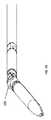
図1A〜図1Cは、例示のアテローム切除カテーテルを示す。図1Aを参照して、アテローム切除カテーテル100は、カテーテル本体101と、駆動シャフト113に装着され、カテーテル本体101の遠位端にあるカッタ103と、カテーテル本体101の遠位端にあるノーズコーン105とを含むことができる。ノーズコーン105はさらに、カッタ103の切断エッジ112が露出できる切断窓を含むことができる。ノーズコーン105は、カテーテル本体の長手方向軸からある角度で偏向するように構成できる。使用の際、この偏向は、カッタ103を切断窓を介して露出でき、及び/又は、カッタ103を、アテローム切除カテーテルが挿入される血管の壁の中に半径方向に押すことができる。図1Dに示すように、カテーテル100はさらに、内蔵式イメージングシステム、例えば、光コヒーレンストモグラフィー(OCT)を含むことができる。OCT撮像素子のための光ファイバ111は、駆動シャフト113の中心を通ることができる。さらに、光ファイバ111は、カッタ103に装着でき、それとともに回転するように構成できる。 1A-1C show exemplary atherectomy catheters. With reference to FIG. 1A, the
さらに、カテーテル100は、イメージングシステムの変位、回転及び/又は撮像能力のための制御を含むハンドル115及び/又は駆動システムを含んでもよい。カテーテル100は、内蔵式イメージングシステムを用いて収集される画像を表示するための制御システム及び/又はイメージングコンソールに装着されるように構成できる。 In addition,
さらに、カテーテル100は、画像歪みを補正する、例えば、回転遅延を補正するように構成された制御システムとともに作動するように構成できる。カテーテルが理想的なトルク伝達物体でないため、カテーテルの近位端が回転した場合にカテーテルの遠位端が回転しないある位相遅延(Θ)が存在するようになる。この位相遅延は、カテーテルがトルクを受け、及び/又は回転の方向が変化した場合、画像の正しくない方位を生じさせることがあり、回転遅延と称される。多くの要因が潜在的な回転遅延に関与することがある。これらは、血管の湾曲部に起因したカテーテルのトルク発生、またはオペレータによって作用される力、カッタ位置、切除されるプラークのタイプ、及び/又は、カテーテルに捩り負荷を付与できる他の要因を含む。 In addition, the
図2は、回転遅延を補正するように構成されたアテローム切除システム200の図を示す。システムは、駆動アセンブリ222を含み、これは、例えば、米国特許出願第14/400151号(2014年11月10日出願、名称「ATHERECTOMY CATHETER DRIVE ASSEMBLIES」、米国特許第9345398号)、およびPCT特許出願PCT/US2016/041193(2016年7月6日出願、名称「SELF-ALIGNMENT MECHANISM FOR IMAGING CATHETER AND DRIVE ASSEMBLY」、国際公開第2017/007853号)に記載されたような駆動アセンブリとすることができ、上記出願の全体は参照によりここに組み込まれる。駆動アセンブリ222は、カテーテルの駆動シャフト213(およびその遠位端にある撮像センサ216)を回転するように構成された駆動シャフトモータ114を含む。駆動シャフトモータ114が回転すると、それは、インデックスパルスを提供し、これは、モータ駆動シャフトが設定された基準ポイント(例えば、上死点位置)を通過する毎に、コントローラ224によって(例えば、151で)読み取り可能である。駆動アセンブリはさらに、駆動シャフトモータを通電する駆動電圧源111を含む。 FIG. 2 shows a diagram of an
使用の際、モータ114は、駆動シャフト213および撮像センサ216を回転して、円周エリア232(例えば、血管などの身体管腔)から画像データを収集できる。画像データは、コントローラ224を通じて返送できる。同時に、コントローラ224は、モータ114のインデックスパルス151を決定できる。そして撮像データは、インデックスに基づいて設定されたタイムスタンプとともにディスプレイに送信でき、例えば、表示されるOCT画像の上部が駆動シャフトでの上死点位置に対応するようにする。しかしながら、トルクが駆動シャフト213に印加されると、もし遅延がインデックスパルスに追加されなければ、表示される画像がセンサ216の実際の位置に対して回転的に不整列(または遅延)するようになる。 During use, the motor 114 can rotate the
こうして電流センサ112が、駆動シャフトモータ114によって引き込まれる電流の連続監視のために、駆動電圧源111と駆動シャフトモータ114との間に配置できる。幾つかの変形例において、電流センサはモータ114と一体化できる。他の変形例において、電流センサ112は、駆動シャフトモータ114と直列に配置された電流センサ抵抗とすることができる。モータ114の瞬間電流は、捩り負荷の関数として変化するようになり、引き込まれる電流は、カテーテルが受ける捩り歪みの関数として変化することを意味する。モータ114の瞬間電流を測定することによって、モータ114での捩り負荷が推測できる。 Thus, the current sensor 112 can be arranged between the
コントローラ224は、115において、カテーテルの遠位端で(即ち、撮像センサ216で)受ける捩り負荷の量と、駆動モータ114から引き込まれる電流の変化との相関関係を得る(即ち、回転遅延を計算する)ように構成できる。回転遅延に基づいて、コントローラ224は、インデックスパルスでの遅延117を実装できる。遅延117は、新しい処理されたインデックスをもたらすことができる。この処理されたインデックス118は、ディスプレイに、OCT画像内のデータの提示を設定時間だけ遅延させるように指示し、画像を元の基準方位と回転的に整列させる(例えば、画像を上死点位置に戻す)。 At 115,
幾つかの実施形態において、回転遅延を補正する方法は、2つの別個のステップ、即ち、(1)システムを較正し、捩り負荷に対して追加のモータ電流引き込みを決定するステップと、(2)続いて使用時のシステムの瞬間モータ電流を決定し、得られる画像での補正を行うステップと、を含むことができる。 In some embodiments, the method of compensating for rotational delay consists of two separate steps: (1) calibrating the system and determining additional motor current draw for the torsional load, and (2). It can then include a step of determining the instantaneous motor current of the system during use and making corrections in the resulting image.
幾つかの実施形態において、第1ステップは、大部分は実験的に実施でき、即ち、1つ以上の異なるモデルのカテーテルを繰り返し試験して、電流の変化と該特定モデルのカテーテルが受ける回転歪み量との間の相関関係を得ることができる。幾つかの実施形態において、2つの重要なパラメータ、オフセット値および利得値がいずれか所定のカテーテルモデルについて計算でき、そして電流と回転歪み量との間の正しい相関関係を決定するために使用される。オフセット値は、遅延がない場合に駆動モータが引き込む電流量に対応する。こうしてオフセット値は、カテーテルが、カッタが閉じている緩和位置にある場合に駆動モータが引き込む電流と等価である。利得値は、測定した電流とオフセット値との間の差に基づいて回転画像の補正を可能にする数値である。 In some embodiments, the first step can be performed mostly experimentally, i.e., by repeatedly testing one or more different model catheters, changes in current and rotational strain that the particular model catheter undergoes. A correlation with the quantity can be obtained. In some embodiments, two important parameters, offset and gain values, can be calculated for any given catheter model and used to determine the correct correlation between current and rotational strain. .. The offset value corresponds to the amount of current drawn by the drive motor when there is no delay. The offset value is thus equivalent to the current drawn by the drive motor when the catheter is in the relaxed position with the cutter closed. The gain value is a numerical value that enables correction of the rotated image based on the difference between the measured current and the offset value.
幾つかの実施形態において、第2ステップは、コントローラによって動的に実施できる。即ち、いったん特定モデルのカテーテルが、回転歪みの関数として捩り抵抗について第1ステップで較正されると(即ち、いったんオフセット値および利得値が該モデルについて決定されると)、該特定のカテーテル/カテーテルモデルについて瞬間回転歪みを推測して、得られた画像に対して適切な量の補正を適用することが可能である。図2を再び参照して、そうすることは、センサ112を用いて瞬間電流を測定することを含むことができる。回転遅延の調整は、カテーテルの使用時に動的に、即ち、ユーザからの指示または入力なしで実施できる。その結果、ユーザは、カテーテルの遠位端または切断領域において光ファイバが検出したものに真に対応する画像を、画像の不要な回転歪みなしで好都合に閲覧できる。 In some embodiments, the second step can be dynamically performed by the controller. That is, once a particular model of catheter has been calibrated for torsional resistance as a function of rotational strain in the first step (ie, once the offset and gain values have been determined for the model), the particular catheter / catheter. It is possible to infer instantaneous rotational distortion for the model and apply an appropriate amount of correction to the resulting image. With reference to FIG. 2 again, doing so can include measuring the instantaneous current with the sensor 112. Adjustment of the rotation delay can be performed dynamically when using the catheter, i.e. without user instruction or input. As a result, the user can conveniently view an image that truly corresponds to what the optical fiber has detected at the distal end or cut region of the catheter, without the unnecessary rotational distortion of the image.
(カテーテルを較正するためのステップ)
図3は、特定モデルのカテーテル、例えば、カテーテル100を較正し、モータによって引き込まれる追加のモータ電流と捩り負荷との間の相関関係を決定するための例示のステップを詳述するフローチャートである。異なるモデルであると考えられるカテーテルは、例えば、駆動シャフトが異なる特性(例えば、寸法、弾性(spring)など)を有するものものでもよく、そのため捩りと電流引き込みとの間の得られる関係は異なるようになる。ステップ121において、基準電流値(オフセット値と称される)が決定される。オフセット値は、カテーテルが本体空洞の外部にあり、カッタが閉じている緩和したアイドル状態にある場合に得られる電流測定値である。ステップ123において、撮像センサを用いて画像が得られるとともに、カテーテルは緩和したアイドル状態にある。このアイドル画像は、特定の設定された方位または回転位置(例えば、画像内のマーカーに基づいて決定できる)を有することができる。(Steps for calibrating the catheter)
FIG. 3 is a flow chart detailing an exemplary step for calibrating a particular model catheter, eg,
ステップ125において、例えば、ノーズコーンを開いてカッタを露出させることによって、あるトルク量が駆動シャフトに印加できる。増加したトルクに起因して、モータによって引き込まれる電流は、オフセットをある量だけ超えるようになる。オフセット値を超えるこの電流変化は、測定され記録できる。そして利得値は、下記(式1)に基づいて決定できる。
R=C(M−O)G (式1)
ここで、Rは半径(radial)調整値(単位は度)(即ち、得られた画像を正しい回転方位に戻すのに要する調整量)、Cは定数(単位は度/A(アンペア))、Oはオフセット値(単位はA)、Mは測定した電流(単位はA)、Gは利得値である。即ち、このステップにおいて、該カテーテルモデルについての適切な利得値は、画像を回転してその元のアイドル位置に戻すように決定できる。(表1)(オフセット、利得およびRの実験的に収集した値を示す)に示すように、利得値は、Rの値に関わらず、特定のカテーテルモデルについて同じにすべきである。このステップは、例えば、実験的に実施できる。In
R = C (MO) G (Equation 1)
Here, R is a radius adjustment value (unit is degree) (that is, the adjustment amount required to return the obtained image to the correct rotation direction), C is a constant (unit is degree / A (ampere)), O is an offset value (unit is A), M is a measured current (unit is A), and G is a gain value. That is, in this step, the appropriate gain value for the catheter model can be determined to rotate the image back to its original idle position. As shown in (Table 1) (showing experimentally collected values for offset, gain and R), the gain values should be the same for a particular catheter model, regardless of the value of R. This step can be performed experimentally, for example.

幾つかの実施形態において、(式1)は、Oより大きいか、これと等しいMについて有効であると考えられる。もしMがOより小さい場合、R(または半径調整)はゼロと考えられる。 In some embodiments, (Equation 1) is considered valid for M greater than or equal to O. If M is less than O, then R (or radius adjustment) is considered zero.
こうして較正ステップにおいて、オフセット値および利得値は、画像を回転してその元の位置に戻すように決定できる(即ち、既知または実測したRを用いて)。そしてステップ129において、特定のカテーテルについての補正が決定できる(即ち、C,G,Oが式1に入力でき、測定した電流(M)に応じて、これから行う回転調整が決定できる)。 Thus, in the calibration step, the offset and gain values can be determined to rotate the image back to its original position (ie, using known or measured R). Then, in
(回転遅延が較正されたカテーテルの使用)
図4は、較正されたカテーテルを用いて回転遅延を動的に補正するためのステップを示すフローチャートである。ステップ131において、オペレータは、特定のカテーテルを選択する。ステップ133において、オペレータは、回転遅延を動的に瞬間的に補正するプログラムを開始する。プログラムは、図3のステップ129から該カテーテルモデルについて決定した補正に基づくことができる。こうして適切な補正が、ステップ135において選択できる(例えば、特定のカテーテルモデル識別番号をコントローラに入力することによって)。ステップ137において、ユーザは、カテーテルを操作できる(例えば、アテローム切除処置の一部として)とともに、プログラムは、オフセット電流値に対して駆動モータに供給される電流を監視する。ステップ139において、もし測定した電流がオフセット値を超えた場合、値Rが得られる(式1および測定した電流に基づいて)。値Rに基づいて、調整または回転の量が画像に適用でき、画像が正しい方位を維持することを確保できる。いったん調整されると、画像は捕獲されて、ユーザのために表示される(ステップ140)。(Use of catheter with calibrated rotation delay)
FIG. 4 is a flow chart showing steps for dynamically compensating for rotation delay using a calibrated catheter. In
決定した半径調整値(R)を使用するために回転遅延が補償/調整される多数の手法がある。一例において、表示される画像は遅延できる。これは、カテーテルの操作時に、イメージングシステム(例えば、OCT)が連続的な流れの撮像データを提供するという実測に基づく。撮像素子が駆動モータとともに掃引する際、画像が半径方向に掃引される。表示される画像は、該画像について得られるデータであり、それは基準(例えば、上死点)に関係するためである。回転遅延が存在して光学素子を捩る場合、駆動アセンブリとして定義されたような上死点と撮像素子の端部で撮影された画像との間で不整列(misalignment)が存在する。撮像素子の端部で真の画像を検出する際に遅延が存在するため、設定時間の間に画像データとともに送信される上死点パルスを意図的に遅延させることによって(式1に基づいて)、表示される画像は、検出された画像と整列できる。こうした実施形態において、時間遅延は、(式2)に従って半径調整値(R)と同等とみなすことができる。
T=(R×60)/(RPM×360) (式2)
ここで、Tは時間(単位は秒)、Rは半径調整値、RPMは駆動モータの速度(単位は回転/分)である。従って、インデックスパルスは、遅延でき、画像の方位(即ち、上死点位置)を維持するように遅延したパルスで駆動アセンブリからディスプレイへ送信できる。幾つかの実施形態において、画像は、駆動アセンブリ内のコントローラを用いて駆動シャフトの回転当り1回(即ち、入力パルス当り1回)調整できる。There are a number of techniques in which the rotation delay is compensated / adjusted to use the determined radius adjustment value (R). In one example, the displayed image can be delayed. This is based on measurements that the imaging system (eg, OCT) provides continuous flow imaging data when manipulating the catheter. When the image sensor sweeps with the drive motor, the image is swept in the radial direction. The displayed image is the data obtained for that image because it relates to a reference (eg, top dead center). When there is a rotation delay and the optics are twisted, there is a misalignment between the top dead center as defined as the drive assembly and the image taken at the end of the image sensor. Since there is a delay in detecting the true image at the end of the image sensor, by intentionally delaying the top dead center pulse transmitted with the image data during the set time (based on Equation 1). , The displayed image can be aligned with the detected image. In such an embodiment, the time delay can be regarded as equivalent to the radius adjustment value (R) according to (Equation 2).
T = (R × 60) / (RPM × 360) (Equation 2)
Here, T is time (unit is seconds), R is radius adjustment value, and RPMM is the speed of the drive motor (unit is rotation / minute). Therefore, the index pulse can be delayed and can be transmitted from the drive assembly to the display with the pulse delayed to maintain the orientation of the image (ie, top dead center position). In some embodiments, the image can be adjusted once per rotation of the drive shaft (ie, once per input pulse) using the controller in the drive assembly.
回転遅延を動的に補正するための方法およびシステムはまた、関連したソフトウェアプログラムと、駆動モータからの電流変化量または他の電気的特性、および回転遅延量の相関関係を得ることができるアプリケーションとを含んでもよい。 Methods and systems for dynamically compensating for rotational delay are also associated with software programs and applications that can obtain correlations of current changes or other electrical characteristics from the drive motor, and rotational delay. May include.
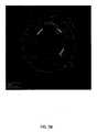
図5A〜図5Cは、動的回転歪み補正を示す。図5Aは、カテーテルカッタが露出しているときの血管のOCT画像を示す。カッタは、12時の位置に示される(反転した馬蹄形状の明るいラインは、カッタを包囲するハウジングに対応するとともに、開口は、カッタおよび撮像した血管のエリアに対応する)。図5Bと図5Cは、カッタが完全に開いた場合に撮像素子によって撮影された画像を示す(補正あり(図5C)と補正なし(図5B))。補正なしでは、図5Bに示すように、画像は、約130度反時計回りに回転しており、露出したカッタは8時の位置にある。血管内のカッタの実際の方位が変化していないと仮定すると、この回転した方位(回転遅延によって生じた)は、ユーザを混乱させることがある。これに対して補正ありでは、図5Cに示すように、カッタは、図5Aでのその位置に対して回転しておらず、依然として約12時の位置に位置決めされる。最終的には、真の方位を備えた身体管腔の画像を見ることができることは、撮像または切除処置のいずれかのための直観的でより効率的な手法をユーザに提供することになる。 5A-5C show dynamic rotational distortion correction. FIG. 5A shows an OCT image of a blood vessel when the catheter cutter is exposed. The cutter is shown at 12 o'clock (the inverted horseshoe-shaped bright line corresponds to the housing surrounding the cutter, and the opening corresponds to the area of the cutter and the imaged vessel). 5B and 5C show images taken by the image sensor when the cutter is fully open (with correction (FIG. 5C) and without correction (FIG. 5B)). Without correction, as shown in FIG. 5B, the image is rotated about 130 degrees counterclockwise and the exposed cutter is at 8 o'clock. This rotated orientation (caused by the rotation delay) can be confusing to the user, assuming that the actual orientation of the cutter in the vessel has not changed. On the other hand, with correction, as shown in FIG. 5C, the cutter does not rotate with respect to that position in FIG. 5A and is still positioned at about 12 o'clock. Ultimately, being able to see an image of the body lumen with a true orientation will provide the user with an intuitive and more efficient method for either imaging or excision procedures.
回転歪みを補正するように構成されたコントローラを駆動アセンブリ内に設置されものとしてここでは説明したが、それは別の場所に位置決めできることは理解すべきである。例えば、一実施形態において、ディスプレイ上のコントローラが電流を連続的に監視でき、従ってセクター図を更新できる。即ち、全ての回転が一定の回転で生じることを想定するよりはむしろ、コントローラは、各回転に渡って電流引き込みをマッピングでき、電流引き込みに従ってパルス間隙を調整できる。 Although a controller configured to compensate for rotational distortion has been described here as being installed within the drive assembly, it should be understood that it can be positioned elsewhere. For example, in one embodiment, the controller on the display can continuously monitor the current and thus update the sector diagram. That is, rather than assuming that all rotations occur at a constant rotation, the controller can map the current draw over each rotation and adjust the pulse gap according to the current draw.
ここで説明する方法およびシステムは、アテローム切除カテーテルまたはイメージングシステムを含む任意のカテーテル内の回転遅延を補正するための簡単な手法を提供する。ここで提供される回転遅延補正は、画像が表示される前に信号を好都合に補正する。この段階での補正は、必要とするステップが少なく、画像を補正するためのソフトウェアプログラムが複雑でない。さらに、ここで説明する方法およびシステムは、受ける回転遅延の連続的な監視および補正を提供するものであり、そのため見える画像は、オペレータの介入の必要なしでイメージングファイバが見るものに常に対応する。 The methods and systems described herein provide a simple method for compensating for rotational delay within any catheter, including an atherectomy catheter or imaging system. The rotation delay correction provided here conveniently corrects the signal before the image is displayed. The correction at this stage requires few steps and the software program for correcting the image is not complicated. In addition, the methods and systems described herein provide continuous monitoring and correction of the rotational delay received so that the visible image always corresponds to what the imaging fiber sees without the need for operator intervention.
幾つかの例において、アナログデジタル変換器が、受信した情報を処理し、信号情報をプロセッサまたはマイクロプロセッサに送信するために使用できる。さらに、信号処理はまた、必要に応じて必須のローパスフィルタを含んでもよい。電流変化は、インデックス化(割り出し)され、処理されて、電流変化と、受けた回転歪み量との間の関係を決定する。最後に本システムは、電流変化を利用して、受けた回転遅延量との相関関係を得るとともに、類似の測定を達成するために、システムの他の電気的特性、例えば、電圧変化、抵抗、インピーダンスなどを使用することも想定できる。 In some examples, an analog-to-digital converter can be used to process the received information and send the signal information to a processor or microprocessor. In addition, signal processing may also include the required low-pass filter, if desired. The current change is indexed (indexed) and processed to determine the relationship between the current change and the amount of rotational strain received. Finally, the system utilizes current changes to obtain correlations with the amount of rotation delay received and to achieve similar measurements with other electrical characteristics of the system, such as voltage changes, resistors, etc. It can be assumed that impedance or the like is used.
回転遅延を補正するための方法およびアセンブリは、種々のカテーテル及び/又はモータアセンブリを用いて使用できる。例えば、方法およびアセンブリは、米国特許出願第15/072272号(2016年3月16日出願、名称「ATHERECTOMY CATHETERS DEVICES HAVING MULTI-CHANNEL BUSHINGS」、公開番号第2016−0192962−A1号)、および米国特許出願第15/076568号(2016年3月31日出願、名称「ATHERECTOMY CATHETERS AND OCCLUSION CROSSING DEVICES」、特許番号第9498247号)に記載されたアテローム切除カテーテルを用いて使用でき、その全体内容は参照によりここに組み込まれる。 Methods and assemblies for compensating for rotational delay can be used with a variety of catheters and / or motor assemblies. For example, methods and assemblies are described in US Patent Application No. 15/072272 (filed March 16, 2016, named "ATHERECTOMY CATHETERS DEVICES HAVING MULTI-CHANNEL BUSHINGS", Publication No. 2016-0192962-A1), and US Patent. It can be used with the atherectomy catheter described in Application No. 15/076568 (filed March 31, 2016, name "ATHERECTOMY CATHETERS AND OCCLUSION CROSSING DEVICES", Patent No. 949824), the entire contents of which can be referred to. It is incorporated here.
ここではOCTシステムを用いて使用されるものとして説明したが、回転遅延を補正するシステムおよび方法は、他のタイプの回転イメージング、例えば、血管内超音波法(IVUS)を用いて使用できる。 Although described herein as being used with an OCT system, systems and methods for correcting rotational delay can be used using other types of rotational imaging, such as intravascular ultrasound (IVUS).
説明したシステムおよび方法において、検知された電流に基づいて、回転遅延を連続的に動的に瞬間的に補正できるプログラムが存在できる。いくつかの実施形態において、プログラムは、ディスプレイアセンブリ及び/又は駆動アセンブリの一部である。他の実施形態において、プログラムは、例えば、ラップトップ、デスクトップ、モバイル装置、タブレットなど、種々の電気通信装置を介して制御できる。 In the systems and methods described, there can be programs that can continuously, dynamically and instantaneously correct the rotation delay based on the detected current. In some embodiments, the program is part of a display assembly and / or drive assembly. In other embodiments, the program can be controlled via various telecommunications devices such as laptops, desktops, mobile devices, tablets and the like.
特徴または要素が、他の特徴または要素の上(on)にあるものとして称している場合、それは他の特徴または要素の上に直接にあってもよく、あるいは、介在する特徴及び/又は要素が存在してもよい。これに対して特徴または要素が、他の特徴または要素の直接に上(directly on)にあると称している場合、介在する特徴及び/又は要素が存在していない。特徴または要素が、他の特徴または要素と接続(connected)、装着(attached)または結合(coupled)していると称している場合、それは他の特徴または要素と直接に接続、装着または結合してもよく、あるいは、介在する特徴及び/又は要素が存在してもよい。これに対して特徴または要素が、他の特徴または要素と直接に接続(directly connected)、直接に装着(directly attached)または直接に結合(directly coupled)していると称している場合、介在する特徴及び/又は要素が存在していない。一実施形態に関して記載または図示しているが、そのように記載または図示された特徴および要素は、他の実施形態に適用できる。他の特徴に「隣接して」配置される構造または特徴への言及は、隣接する特徴の上に重なるか、または下に位置する部分を有してもよいことは当業者によって理解されよう。 When a feature or element is referred to as being on top of another feature or element, it may be directly on top of the other feature or element, or an intervening feature and / or element May exist. On the other hand, if a feature or element is said to be directly on, there are no intervening features and / or elements. When a feature or element is said to be connected, attached or coupled to another feature or element, it is directly connected, attached or coupled to the other feature or element. Alternatively, there may be intervening features and / or elements. In contrast, if a feature or element is referred to as being directly connected, directly attached, or directly coupled to another feature or element, then the intervening feature. And / or the element is absent. Although described or illustrated with respect to one embodiment, the features and elements so described or illustrated are applicable to other embodiments. It will be appreciated by those skilled in the art that references to structures or features that are placed "adjacent" to other features may have portions that are above or below the adjacent features.
ここで使用する用語は、特定の実施形態だけを説明する目的のためであり、本発明を限定することを意図していない。例えば、ここで使用するように、単数形「a」、「an」および「the」は、文脈がそれ以外を明確に示していない限り、複数形も含むことを意図している。用語「備える、含む(comprises)」及び/又は「備える、含む(comprising)」は、本明細書で使用する場合、記述された特徴、ステップ、動作、要素及び/又は構成要素の存在を特定するが、1つ以上の他の特徴、ステップ、動作、要素、構成要素及び/又はそれらのグループの存在または追加を排除しないことはさらに理解されよう。ここで使用するように、用語「及び/又は」は、関連して列挙された項目の1つ以上の任意および全ての組合せを含み、「/」と省略することがある。 The terms used herein are for the purpose of describing only certain embodiments and are not intended to limit the invention. For example, as used here, the singular forms "a", "an" and "the" are intended to include the plural unless the context explicitly indicates otherwise. The terms "comprises" and / or "comprising" as used herein identify the presence of the described features, steps, actions, elements and / or components. It will be further understood that does not preclude the existence or addition of one or more other features, steps, actions, elements, components and / or groups thereof. As used herein, the term "and / or" includes any and all combinations of one or more of the items listed in association and may be abbreviated as "/".
空間的に相対的な用語、例えば、「下(under)」、「下(below)」、「下(lower)」、「上(over)」、「上(upper)」などは、図に示すように、1つの要素または特徴についての他の要素または特徴との関係を説明する説明の容易のためにここでは使用することがある。空間的に相対的な用語は、図面に描かれている向きに加えて、使用中または動作中の装置の異なる向きを包含することを意図していることは理解されよう。例えば、図の中の装置が反転している場合、他の要素または特徴の「下(under)」または「下(beneath)」にあるものと記載された要素は、他の要素または特徴の「上(over)」に配向される。こうして例示的な用語「下(under)」は、上(over)および下(under)の向きの両方を包含できる。装置は、他の方向に向いていてもよく(90度または他の向きに回転してもよく)、ここで使用する空間的に相対的な記述語は相応に解釈される。同様に、用語「上向き(upwardly)」、「下向き(downwardly)」、「垂直(vertical)」、「水平(horizontal)」などは、特にそれ以外に示していない限り、説明の目的のためだけに使用される。 Spatial relative terms such as "under", "below", "lower", "over", "upper", etc. are shown in the figure. As such, it may be used herein for ease of explanation to illustrate the relationship of one element or feature with another element or feature. It will be appreciated that spatially relative terms are intended to include different orientations of the device in use or in operation, in addition to the orientations depicted in the drawings. For example, if the device in the figure is inverted, an element described as being "under" or "beneath" of another element or feature is a "under" or "beneath" of another element or feature. Oriented to "over". Thus, the exemplary term "under" can include both over and under orientations. The device may be oriented in the other direction (rotated 90 degrees or in any other direction), and the spatially relative descriptive terms used herein are interpreted accordingly. Similarly, the terms "upwardly," "downwardly," "vertical," "horizontal," etc. are for explanatory purposes only, unless otherwise indicated. used.
用語「第1」および「第2」は、種々の特徴/要素(ステップを含む)を記載するためにここでは使用することがあるが、これらの特徴/要素は、文脈がそれ以外を示していない限り、これらの用語によって限定されるべきはない。これらの用語は、1つの特徴/要素を他の特徴/要素と区別するために使用することがある。こうして後述する第1の特徴/要素は、第2の特徴/要素と称することができ、同様に、本発明の教示から逸脱することなく、後述する第2の特徴/要素は、第1の特徴/要素と称することができる。 The terms "first" and "second" may be used herein to describe various features / elements (including steps), but these features / elements indicate otherwise in context. Unless it is, it should not be limited by these terms. These terms may be used to distinguish one feature / element from another. Thus, the first feature / element described below can be referred to as the second feature / element, and similarly, without departing from the teachings of the present invention, the second feature / element described below is the first feature. Can be called / element.
本明細書および下記請求項を通じて、文脈がそれ以外を要求しない限り、用語「備える(comprise)」および「備える(comprises), (comprising)」などの変形は、種々の構成要素が方法および物品(例えば、組成物、デバイスを含む装置、方法)で共同で採用できることを意味する。例えば、用語「備える(comprising)」は、任意の記述した要素またはステップの包含を意味し、任意の他の要素またはステップの排除を意味しないことは理解されよう。 Throughout this specification and the following claims, variations such as the terms "comprise" and "comprises, (comprising)" are various components of the method and article, unless the context otherwise requires. For example, it means that the composition, the device including the device, the method) can be jointly adopted. For example, it will be understood that the term "comprising" means the inclusion of any described element or step and not the exclusion of any other element or step.
明細書および請求項で使用したように、例において使用されるものを含み、別に明白に特定していない限り、全ての数値は、用語、約(about, approximately)によって前置きされているように、たとえこの用語が明白に現れていなくても読み取られる。用語、約(about, approximately)は、大きさ及び/又は位置を記述する場合、記述した値及び/又は位置が、値及び/又は位置の合理的な予想される範囲内にあることを示すために使用することがある。例えば、ある数値が、記述した値(または値の範囲)の±0.1%、記述した値(または値の範囲)の±1%、記述した値(または値の範囲)の±2%、記述した値(または値の範囲)の±5%、記述した値(または値の範囲)の±10%などである値を有してもよい。ここで記載した任意の数値範囲は、ここに包含される全ての部分範囲を含むことを意図している。 As used in the specification and claims, all numbers, including those used in the examples, are prefaced by the term, about, approximately, unless otherwise explicitly specified. It is read even if the term does not appear explicitly. When describing the size and / or position, the term about, approximately indicates that the value and / or position described is within a reasonable and expected range of the value and / or position. May be used for. For example, a number is ± 0.1% of the described value (or range of values), ± 1% of the described value (or range of values), ± 2% of the described value (or range of values), It may have a value such as ± 5% of the described value (or range of values), ± 10% of the described value (or range of values), and the like. Any numerical range described herein is intended to include all subranges contained herein.
種々の例示の実施形態を上述したが、請求項に記載された本発明の範囲から逸脱することなく、種々実施形態に対して多くの変更を行うことができる。例えば、説明された種々の方法ステップが実行される順序は、代替の実施形態ではしばしば変更してもよく、他の代替の実施形態では、1つ以上の方法ステップを完全にスキップすることがある。種々の装置およびシステムの実施形態の任意の特徴は、幾つかの実施形態に含まれてもよく、他の実施形態に含まれなくてもよい。従って、上記の説明は、主として例示的な目的のために提供され、請求項に記載されるような本発明の範囲を限定するものと解釈されるべきではない。 Although various exemplary embodiments have been described above, many modifications can be made to the various embodiments without departing from the scope of the invention described in the claims. For example, the order in which the various method steps described are performed may often change in alternative embodiments, and in other alternative embodiments, one or more method steps may be skipped altogether. .. Any feature of the various device and system embodiments may or may not be included in some embodiments. Therefore, the above description is provided primarily for exemplary purposes and should not be construed as limiting the scope of the invention as set forth in the claims.
ここに含まれる例および図解は、説明の一例として、限定することなく、主題を実施できる特定の実施形態を示す。上述したように、他の実施形態を利用し、そこから導出してもよく、本開示の範囲から逸脱することなく構造的および論理的な置換および変更を行うことができる。発明主題のこうした実施形態は、もし2つ以上の発明が実際に開示されていても、単に便宜上で、本願の範囲を任意の単一の発明または発明の概念に自発的に限定することを意図することなく、用語「発明」によって個々にまたは集合的に言及することがある。従って、特定の実施形態をここでは図示し説明したが、同じ目的を達成するために計算された任意の構成を、図示した特定の実施形態に置換してもよい。本開示は、種々の実施形態の任意および全ての適合または変形をカバーすることを意図している。上記実施形態の組合せ、およびここに具体的に記載されていない他の実施形態は、上記説明を検討する際に当業者にとって明らかになるであろう。 The examples and illustrations contained herein, as an example of the description, show a particular embodiment in which the subject can be practiced without limitation. As mentioned above, other embodiments may be utilized and derived from them, and structural and logical substitutions and modifications can be made without departing from the scope of the present disclosure. Such embodiments of the subject matter are intended to voluntarily limit the scope of the present application to any single invention or concept of invention, even if two or more inventions are actually disclosed, for convenience only. It may be referred to individually or collectively by the term "invention" without doing so. Therefore, although specific embodiments have been illustrated and described herein, any configuration calculated to achieve the same objective may be replaced with the specific embodiments shown. The present disclosure is intended to cover any and all adaptations or variations of various embodiments. Combinations of the above embodiments, and other embodiments not specifically described herein, will be apparent to those skilled in the art when considering the above description.
Claims (14)
Translated fromJapanese駆動シャフトの遠位端に対して固定され、それとともに回転するように構成された撮像センサと、
駆動シャフトを回転するように構成された駆動モータと、
駆動シャフトが回転すると、駆動モータによって引き込まれる電流量を測定するように構成されたセンサと、
撮像センサが回転すると、撮像センサによって得られる1つ以上の画像を表示するように構成されたディスプレイと、
測定した電流に基づいて、ディスプレイによって表示される1つ以上の画像の回転方位を調整するように構成されたコントローラと、を備えるカテーテルシステム。A catheter body with a drive shaft and
An imaging sensor that is fixed to the distal end of the drive shaft and configured to rotate with it.
With a drive motor configured to rotate the drive shaft,
A sensor configured to measure the amount of current drawn by the drive motor as the drive shaft rotates,
A display configured to display one or more images obtained by the imaging sensor as the imaging sensor rotates, and
A catheter system comprising a controller configured to adjust the orientation of one or more images displayed by a display based on the measured current.
駆動シャフトが第1インデックスパルスで回転すると、駆動モータによって引き込まれる電流量を測定するように構成されたセンサと、
測定した電流および第1インデックスパルスに基づいて、第2インデックスパルスを決定し、第2インデックスパルスは、第1インデックスパルスに対して遅延しており、そして、第2インデックスパルスをディスプレイに送信し、回転遅延について調整された撮像センサによって収集された画像の表示を可能にするコントローラと、を備えるカテーテル駆動アセンブリ。A drive motor configured to rotate the catheter drive shaft and imaging sensor with a first index pulse,
A sensor configured to measure the amount of current drawn by the drive motor as the drive shaft rotates with the first index pulse.
Based on the measured current and the first index pulse, the second index pulse is determined, the second index pulse is delayed relative to the first index pulse, and the second index pulse is transmitted to the display. A catheter-driven assembly with a controller that allows the display of images collected by an imaging sensor tuned for rotation delay.
Applications Claiming Priority (3)
| Application Number | Priority Date | Filing Date | Title |
|---|---|---|---|
| US201662286918P | 2016-01-25 | 2016-01-25 | |
| US62/286,918 | 2016-01-25 | ||
| PCT/US2017/014921WO2017132247A1 (en) | 2016-01-25 | 2017-01-25 | Oct imaging catheter with lag correction |
Publications (2)
| Publication Number | Publication Date |
|---|---|
| JP2019508101A JP2019508101A (en) | 2019-03-28 |
| JP6927986B2true JP6927986B2 (en) | 2021-09-01 |
Family
ID=59398805
Family Applications (1)
| Application Number | Title | Priority Date | Filing Date |
|---|---|---|---|
| JP2018538773AActiveJP6927986B2 (en) | 2016-01-25 | 2017-01-25 | OCT imaging catheter with delay compensation |
Country Status (7)
| Country | Link |
|---|---|
| US (1) | US11278248B2 (en) |
| EP (1) | EP3407777B1 (en) |
| JP (1) | JP6927986B2 (en) |
| CN (1) | CN108882857A (en) |
| AU (1) | AU2017212407A1 (en) |
| CA (1) | CA3012186A1 (en) |
| WO (1) | WO2017132247A1 (en) |
Families Citing this family (27)
| Publication number | Priority date | Publication date | Assignee | Title |
|---|---|---|---|---|
| US9125562B2 (en) | 2009-07-01 | 2015-09-08 | Avinger, Inc. | Catheter-based off-axis optical coherence tomography imaging system |
| US9788790B2 (en) | 2009-05-28 | 2017-10-17 | Avinger, Inc. | Optical coherence tomography for biological imaging |
| US8696695B2 (en) | 2009-04-28 | 2014-04-15 | Avinger, Inc. | Guidewire positioning catheter |
| WO2011003006A2 (en) | 2009-07-01 | 2011-01-06 | Avinger, Inc. | Atherectomy catheter with laterally-displaceable tip |
| US10548478B2 (en) | 2010-07-01 | 2020-02-04 | Avinger, Inc. | Balloon atherectomy catheters with imaging |
| US11382653B2 (en) | 2010-07-01 | 2022-07-12 | Avinger, Inc. | Atherectomy catheter |
| EP2691038B1 (en) | 2011-03-28 | 2016-07-20 | Avinger, Inc. | Occlusion-crossing devices, imaging, and atherectomy devices |
| US9949754B2 (en) | 2011-03-28 | 2018-04-24 | Avinger, Inc. | Occlusion-crossing devices |
| US9345406B2 (en) | 2011-11-11 | 2016-05-24 | Avinger, Inc. | Occlusion-crossing devices, atherectomy devices, and imaging |
| EP2849660B1 (en) | 2012-05-14 | 2021-08-25 | Avinger, Inc. | Atherectomy catheter drive assemblies |
| US9557156B2 (en) | 2012-05-14 | 2017-01-31 | Avinger, Inc. | Optical coherence tomography with graded index fiber for biological imaging |
| US11284916B2 (en) | 2012-09-06 | 2022-03-29 | Avinger, Inc. | Atherectomy catheters and occlusion crossing devices |
| US9498247B2 (en) | 2014-02-06 | 2016-11-22 | Avinger, Inc. | Atherectomy catheters and occlusion crossing devices |
| CN105228514B (en) | 2013-03-15 | 2019-01-22 | 阿维格公司 | Optical Pressure Sensor Assembly |
| WO2014143064A1 (en) | 2013-03-15 | 2014-09-18 | Avinger, Inc. | Chronic total occlusion crossing devices with imaging |
| US11096717B2 (en) | 2013-03-15 | 2021-08-24 | Avinger, Inc. | Tissue collection device for catheter |
| EP3019096B1 (en) | 2013-07-08 | 2023-07-05 | Avinger, Inc. | System for identification of elastic lamina to guide interventional therapy |
| MX2016010141A (en) | 2014-02-06 | 2017-04-06 | Avinger Inc | Atherectomy catheters and occlusion crossing devices. |
| US10357277B2 (en) | 2014-07-08 | 2019-07-23 | Avinger, Inc. | High speed chronic total occlusion crossing devices |
| US10568520B2 (en) | 2015-07-13 | 2020-02-25 | Avinger, Inc. | Micro-molded anamorphic reflector lens for image guided therapeutic/diagnostic catheters |
| JP6927986B2 (en) | 2016-01-25 | 2021-09-01 | アビンガー・インコーポレイテッドAvinger, Inc. | OCT imaging catheter with delay compensation |
| EP3435892B1 (en) | 2016-04-01 | 2024-04-03 | Avinger, Inc. | Atherectomy catheter with serrated cutter |
| US11344327B2 (en) | 2016-06-03 | 2022-05-31 | Avinger, Inc. | Catheter device with detachable distal end |
| WO2018006041A1 (en) | 2016-06-30 | 2018-01-04 | Avinger, Inc. | Atherectomy catheter with shapeable distal tip |
| US12167867B2 (en) | 2018-04-19 | 2024-12-17 | Avinger, Inc. | Occlusion-crossing devices |
| CN114746033B (en) | 2019-10-18 | 2025-01-10 | 阿维格公司 | Blocking crossing device |
| JP7727586B2 (en)* | 2022-03-30 | 2025-08-21 | テルモ株式会社 | Information processing method, program, and information processing device |
Family Cites Families (568)
| Publication number | Priority date | Publication date | Assignee | Title |
|---|---|---|---|---|
| US3367727A (en) | 1965-10-22 | 1968-02-06 | Abraham W. Ward | Oral surgery tool with interchangeable blades |
| US3908637A (en) | 1974-04-22 | 1975-09-30 | Louis W Doroshow | Rigid urethral instrument |
| GB1531659A (en) | 1977-07-21 | 1978-11-08 | Gekhman B | Apparatus for disintegration of urinary concretions |
| US4527553A (en) | 1980-04-28 | 1985-07-09 | Upsher Michael S | Laryngoscope with improved light source |
| US4578061A (en) | 1980-10-28 | 1986-03-25 | Lemelson Jerome H | Injection catheter and method |
| US5435805A (en) | 1992-08-12 | 1995-07-25 | Vidamed, Inc. | Medical probe device with optical viewing capability |
| US4621353A (en) | 1982-09-09 | 1986-11-04 | Burroughs Corporation | Optical memory system providing improved focusing control and improved beam combining and separating apparatus |
| US4487206A (en) | 1982-10-13 | 1984-12-11 | Honeywell Inc. | Fiber optic pressure sensor with temperature compensation and reference |
| FR2541784B1 (en) | 1983-02-25 | 1986-05-16 | Thomson Csf | DEVICE FOR STATIC DEFLECTION OF AN INFRARED BEAM |
| US4611600A (en) | 1983-11-21 | 1986-09-16 | Cordis Corporation | Optical fiber pressure transducer |
| US5178153A (en) | 1984-03-08 | 1993-01-12 | Einzig Robert E | Fluid flow sensing apparatus for in vivo and industrial applications employing novel differential optical fiber pressure sensors |
| US5041082A (en) | 1986-06-16 | 1991-08-20 | Samuel Shiber | Mechanical atherectomy system and method |
| US4781186A (en) | 1984-05-30 | 1988-11-01 | Devices For Vascular Intervention, Inc. | Atherectomy device having a flexible housing |
| US4926858A (en) | 1984-05-30 | 1990-05-22 | Devices For Vascular Intervention, Inc. | Atherectomy device for severe occlusions |
| US4552554A (en) | 1984-06-25 | 1985-11-12 | Medi-Tech Incorporated | Introducing catheter |
| US4651753A (en) | 1984-10-12 | 1987-03-24 | Jayco Pharmaceuticals | Endoscopic multiple biopsy instrument |
| US4686982A (en) | 1985-06-19 | 1987-08-18 | John Nash | Spiral wire bearing for rotating wire drive catheter |
| US4681106A (en) | 1985-08-12 | 1987-07-21 | Intravascular Surgical Instruments, Inc. | Catheter based surgical methods and apparatus therefor |
| US4654024A (en) | 1985-09-04 | 1987-03-31 | C.R. Bard, Inc. | Thermorecanalization catheter and method for use |
| US5182291A (en) | 1986-02-14 | 1993-01-26 | Sanofi | Pyrozala-pyridyl aminoabkoxyphenol compounds |
| US5000185A (en) | 1986-02-28 | 1991-03-19 | Cardiovascular Imaging Systems, Inc. | Method for intravascular two-dimensional ultrasonography and recanalization |
| US4771774A (en) | 1986-02-28 | 1988-09-20 | Devices For Vascular Intervention, Inc. | Motor drive unit |
| US4691708A (en) | 1986-03-10 | 1987-09-08 | Cordis Corporation | Optical pressure sensor for measuring blood pressure |
| JPH0732758B2 (en) | 1986-05-21 | 1995-04-12 | オリンパス光学工業株式会社 | Endoscope |
| US4729763A (en) | 1986-06-06 | 1988-03-08 | Henrie Rodney A | Catheter for removing occlusive material |
| SE453561B (en) | 1986-06-25 | 1988-02-15 | Radisensor Ab | MINIATURIZED SENSOR FOR PHYSIOLOGICAL PRESSURE SEATS |
| US4841977A (en) | 1987-05-26 | 1989-06-27 | Inter Therapy, Inc. | Ultra-thin acoustic transducer and balloon catheter using same in imaging array subassembly |
| US4857046A (en) | 1987-10-21 | 1989-08-15 | Cordis Corporation | Drive catheter having helical pump drive shaft |
| US5047040A (en) | 1987-11-05 | 1991-09-10 | Devices For Vascular Intervention, Inc. | Atherectomy device and method |
| US4920961A (en) | 1988-06-02 | 1990-05-01 | Circon Corporation | System for disconnetably mounting an endoscope sheath with an endoscope tool |
| EP0347098B1 (en) | 1988-06-13 | 1996-02-28 | Samuel Shiber | Atherectomy system with a guide-wire |
| SE460396B (en) | 1988-07-29 | 1989-10-09 | Radisensor Ab | MINIATURIZED SENSOR DEVICE FOR SEATING PHYSIOLOGICAL PRESSURE IN VIVO |
| US5099850A (en) | 1989-01-17 | 1992-03-31 | Olympus Optical Co., Ltd. | Ultrasonic diagnostic apparatus |
| US5431673A (en) | 1989-02-17 | 1995-07-11 | American Biomed, Inc. | Distal atherectomy catheter |
| US5226909A (en) | 1989-09-12 | 1993-07-13 | Devices For Vascular Intervention, Inc. | Atherectomy device having helical blade and blade guide |
| US5085662A (en) | 1989-11-13 | 1992-02-04 | Scimed Life Systems, Inc. | Atherectomy catheter and related components |
| US5054501A (en) | 1990-05-16 | 1991-10-08 | Brigham & Women's Hospital | Steerable guide wire for cannulation of tubular or vascular organs |
| US5674232A (en) | 1990-06-05 | 1997-10-07 | Halliburton; Alexander George | Catheter and method of use thereof |
| BE1003189A5 (en) | 1990-07-27 | 1992-01-07 | B A Cosurvey Optics S P R L B | PRESSURE SENSOR. |
| WO1992002276A1 (en) | 1990-08-06 | 1992-02-20 | Acculase, Inc. | Fiber optic laser catheter and method of use |
| US5142155A (en) | 1991-03-11 | 1992-08-25 | Hewlett-Packard Company | Catheter tip fluorescence-quenching fiber optic pressure sensor |
| US5465147A (en) | 1991-04-29 | 1995-11-07 | Massachusetts Institute Of Technology | Method and apparatus for acquiring images using a ccd detector array and no transverse scanner |
| JP3479069B2 (en) | 1991-04-29 | 2003-12-15 | マサチューセッツ・インステチュート・オブ・テクノロジー | Method and apparatus for optical imaging and measurement |
| US5956355A (en) | 1991-04-29 | 1999-09-21 | Massachusetts Institute Of Technology | Method and apparatus for performing optical measurements using a rapidly frequency-tuned laser |
| US6501551B1 (en) | 1991-04-29 | 2002-12-31 | Massachusetts Institute Of Technology | Fiber optic imaging endoscope interferometer with at least one faraday rotator |
| US6134003A (en) | 1991-04-29 | 2000-10-17 | Massachusetts Institute Of Technology | Method and apparatus for performing optical measurements using a fiber optic imaging guidewire, catheter or endoscope |
| US6485413B1 (en) | 1991-04-29 | 2002-11-26 | The General Hospital Corporation | Methods and apparatus for forward-directed optical scanning instruments |
| US6564087B1 (en) | 1991-04-29 | 2003-05-13 | Massachusetts Institute Of Technology | Fiber optic needle probes for optical coherence tomography imaging |
| US7074231B2 (en) | 1991-06-13 | 2006-07-11 | Advanced Cardiovascular Systems, Inc. | Convertible mode vascular catheter system |
| US5190050A (en) | 1991-11-08 | 1993-03-02 | Electro-Catheter Corporation | Tip deflectable steerable catheter |
| WO1993013716A1 (en) | 1992-01-13 | 1993-07-22 | Schneider (Usa) Inc. | Surgical cutting tool |
| US5192291A (en) | 1992-01-13 | 1993-03-09 | Interventional Technologies, Inc. | Rotationally expandable atherectomy cutter assembly |
| GB9207532D0 (en) | 1992-04-07 | 1992-05-20 | Innovata Biomed Ltd | Medical connection system |
| JPH0627343A (en) | 1992-07-06 | 1994-02-04 | Nippon Telegr & Teleph Corp <Ntt> | Optical fiber juncture for optical fiber amplifier |
| US5312415A (en) | 1992-09-22 | 1994-05-17 | Target Therapeutics, Inc. | Assembly for placement of embolic coils using frictional placement |
| US5383460A (en) | 1992-10-05 | 1995-01-24 | Cardiovascular Imaging Systems, Inc. | Method and apparatus for ultrasound imaging and atherectomy |
| US5333142A (en) | 1992-10-26 | 1994-07-26 | The United States Of America As Represented By The Secretary Of The Navy | Technique for intracavity sum frequency generation |
| US5643297A (en) | 1992-11-09 | 1997-07-01 | Endovascular Instruments, Inc. | Intra-artery obstruction clearing apparatus and methods |
| US5383467A (en) | 1992-11-18 | 1995-01-24 | Spectrascience, Inc. | Guidewire catheter and apparatus for diagnostic imaging |
| US5460168A (en) | 1992-12-25 | 1995-10-24 | Olympus Optical Co., Ltd. | Endoscope cover assembly and cover-system endoscope |
| US5372601A (en) | 1993-03-30 | 1994-12-13 | Lary; Banning G. | Longitudinal reciprocating incisor |
| US5429136A (en) | 1993-04-21 | 1995-07-04 | Devices For Vascular Intervention, Inc. | Imaging atherectomy apparatus |
| WO1994024962A1 (en) | 1993-04-28 | 1994-11-10 | Focal, Inc. | Apparatus and methods for intraluminal photothermoforming |
| US5868778A (en) | 1995-10-27 | 1999-02-09 | Vascular Solutions, Inc. | Vascular sealing apparatus and method |
| US6017359A (en) | 1993-05-25 | 2000-01-25 | Vascular Solutions, Inc. | Vascular sealing apparatus |
| US5951583A (en) | 1993-05-25 | 1999-09-14 | Vascular Solutions, Inc. | Thrombin and collagen procoagulant and process for making the same |
| US5383896A (en) | 1993-05-25 | 1995-01-24 | Gershony; Gary | Vascular sealing device |
| US5579767A (en) | 1993-06-07 | 1996-12-03 | Prince; Martin R. | Method for imaging abdominal aorta and aortic aneurysms |
| US5366464A (en) | 1993-07-22 | 1994-11-22 | Belknap John C | Atherectomy catheter device |
| CH687228A5 (en) | 1993-09-15 | 1996-10-31 | Synthes Ag | Drill head. |
| CA2173482A1 (en) | 1993-10-07 | 1995-04-13 | Erik Andersen | Dilatation catheter |
| US5507760A (en) | 1993-11-09 | 1996-04-16 | Devices For Vascular Intervention, Inc. | Cutter device |
| JPH07184888A (en)* | 1993-12-27 | 1995-07-25 | Toshiba Corp | Ultrasonic diagnostic equipment |
| US5437284A (en) | 1993-12-30 | 1995-08-01 | Camino Laboratories, Inc. | System and method for in vivo calibration of a sensor |
| US5517998A (en) | 1994-01-24 | 1996-05-21 | Medamicus, Inc. | Closed loop pressure determination system and method for fiber optic pressure transducer system |
| JP2869020B2 (en) | 1994-03-23 | 1999-03-10 | 康男 橋本 | Cancer treatment device |
| DE69514262T2 (en) | 1994-03-23 | 2001-10-11 | Hamamatsu Photonics K.K., Hamamatsu | Optical fiber catheter |
| US5507795A (en) | 1994-04-29 | 1996-04-16 | Devices For Vascular Intervention, Inc. | Catheter with perfusion system |
| US6032673A (en) | 1994-10-13 | 2000-03-07 | Femrx, Inc. | Methods and devices for tissue removal |
| US5836957A (en) | 1994-12-22 | 1998-11-17 | Devices For Vascular Intervention, Inc. | Large volume atherectomy device |
| US5632754A (en) | 1994-12-23 | 1997-05-27 | Devices For Vascular Intervention | Universal catheter with interchangeable work element |
| DE19504261A1 (en) | 1995-02-09 | 1996-09-12 | Krieg Gunther | Angioplasty catheter for dilating and / or opening blood vessels |
| US5681336A (en) | 1995-09-07 | 1997-10-28 | Boston Scientific Corporation | Therapeutic device for treating vien graft lesions |
| WO1997010748A1 (en) | 1995-09-20 | 1997-03-27 | Texas Heart Institute | Detecting thermal discrepancies in vessel walls |
| US6615071B1 (en) | 1995-09-20 | 2003-09-02 | Board Of Regents, The University Of Texas System | Method and apparatus for detecting vulnerable atherosclerotic plaque |
| US5556405A (en) | 1995-10-13 | 1996-09-17 | Interventional Technologies Inc. | Universal dilator with reciprocal incisor |
| US6375615B1 (en) | 1995-10-13 | 2002-04-23 | Transvascular, Inc. | Tissue penetrating catheters having integral imaging transducers and their methods of use |
| RU2185859C2 (en) | 1995-10-20 | 2002-07-27 | Надим М. Закка | Device for removing stenoses and supporting vascular walls |
| US5907425A (en) | 1995-12-19 | 1999-05-25 | The Board Of Trustees Of The Leland Stanford Junior University | Miniature scanning confocal microscope |
| SE9601541D0 (en) | 1995-11-08 | 1996-04-23 | Pacesetter Ab | Guidewire assembly |
| US5843050A (en) | 1995-11-13 | 1998-12-01 | Micro Therapeutics, Inc. | Microcatheter |
| SE9504334D0 (en) | 1995-12-04 | 1995-12-04 | Pacesetter Ab | Guidewire assembly |
| US5733296A (en) | 1996-02-06 | 1998-03-31 | Devices For Vascular Intervention | Composite atherectomy cutter |
| NL1003172C2 (en) | 1996-05-20 | 1997-11-21 | Cordis Europ | Catheter insertion sheath with occlusion balloon. |
| ATE279883T1 (en) | 1996-06-11 | 2004-11-15 | Roke Manor Research | CATHETER TRACKING SYSTEM |
| US5795295A (en) | 1996-06-25 | 1998-08-18 | Carl Zeiss, Inc. | OCT-assisted surgical microscope with multi-coordinate manipulator |
| US6830577B2 (en) | 1996-07-26 | 2004-12-14 | Kensey Nash Corporation | System and method of use for treating occluded vessels and diseased tissue |
| US5779721A (en) | 1996-07-26 | 1998-07-14 | Kensey Nash Corporation | System and method of use for revascularizing stenotic bypass grafts and other blood vessels |
| US6080170A (en) | 1996-07-26 | 2000-06-27 | Kensey Nash Corporation | System and method of use for revascularizing stenotic bypass grafts and other occluded blood vessels |
| US6929481B1 (en) | 1996-09-04 | 2005-08-16 | Immersion Medical, Inc. | Interface device and method for interfacing instruments to medical procedure simulation systems |
| US5830145A (en) | 1996-09-20 | 1998-11-03 | Cardiovascular Imaging Systems, Inc. | Enhanced accuracy of three-dimensional intraluminal ultrasound (ILUS) image reconstruction |
| US5722403A (en) | 1996-10-28 | 1998-03-03 | Ep Technologies, Inc. | Systems and methods using a porous electrode for ablating and visualizing interior tissue regions |
| US5904651A (en) | 1996-10-28 | 1999-05-18 | Ep Technologies, Inc. | Systems and methods for visualizing tissue during diagnostic or therapeutic procedures |
| US5872879A (en) | 1996-11-25 | 1999-02-16 | Boston Scientific Corporation | Rotatable connecting optical fibers |
| JPH10161018A (en) | 1996-11-27 | 1998-06-19 | Olympus Optical Co Ltd | Optical system |
| US5899915A (en) | 1996-12-02 | 1999-05-04 | Angiotrax, Inc. | Apparatus and method for intraoperatively performing surgery |
| US6120516A (en) | 1997-02-28 | 2000-09-19 | Lumend, Inc. | Method for treating vascular occlusion |
| US6508825B1 (en) | 1997-02-28 | 2003-01-21 | Lumend, Inc. | Apparatus for treating vascular occlusions |
| US6010449A (en) | 1997-02-28 | 2000-01-04 | Lumend, Inc. | Intravascular catheter system for treating a vascular occlusion |
| US6183487B1 (en) | 1997-03-06 | 2001-02-06 | Scimed Life Systems, Inc. | Ablation device for reducing damage to vessels and/or in-vivo stents |
| US5843103A (en) | 1997-03-06 | 1998-12-01 | Scimed Life Systems, Inc. | Shaped wire rotational atherectomy device |
| US6758854B1 (en) | 1997-05-09 | 2004-07-06 | St. Jude Medical | Splittable occlusion balloon sheath and process of use |
| US5851212A (en) | 1997-06-11 | 1998-12-22 | Endius Incorporated | Surgical instrument |
| US6048349A (en) | 1997-07-09 | 2000-04-11 | Intraluminal Therapeutics, Inc. | Systems and methods for guiding a medical instrument through a body |
| US6013072A (en) | 1997-07-09 | 2000-01-11 | Intraluminal Therapeutics, Inc. | Systems and methods for steering a catheter through body tissue |
| US5987995A (en) | 1997-07-17 | 1999-11-23 | Sentec Corporation | Fiber optic pressure catheter |
| WO1999004700A1 (en) | 1997-07-24 | 1999-02-04 | Mcguckin James F Jr | Urinary catheter |
| GB9717580D0 (en) | 1997-08-19 | 1997-10-22 | Curry Paul | Device for opening blocked tubes |
| US6402719B1 (en) | 1997-09-05 | 2002-06-11 | Cordis Webster, Inc. | Steerable DMR catheter with infusion tube |
| JPH11221229A (en) | 1997-09-24 | 1999-08-17 | Eclipse Surgical Technol Inc | Catheter |
| US6193676B1 (en) | 1997-10-03 | 2001-02-27 | Intraluminal Therapeutics, Inc. | Guide wire assembly |
| US5951482A (en) | 1997-10-03 | 1999-09-14 | Intraluminal Therapeutics, Inc. | Assemblies and methods for advancing a guide wire through body tissue |
| CA2309428A1 (en) | 1997-11-07 | 1999-05-20 | Prolifix Medical, Inc. | Methods and systems for treating obstructions in a body lumen |
| US6183432B1 (en) | 1997-11-13 | 2001-02-06 | Lumend, Inc. | Guidewire and catheter with rotating and reciprocating symmetrical or asymmetrical distal tip |
| US5938671A (en) | 1997-11-14 | 1999-08-17 | Reflow, Inc. | Recanalization apparatus and devices for use therein and method |
| US6110164A (en) | 1997-12-05 | 2000-08-29 | Intratherapeutics, Inc. | Guideless catheter segment |
| US6027514A (en) | 1997-12-17 | 2000-02-22 | Fox Hollow Technologies, Inc. | Apparatus and method for removing occluding material from body lumens |
| US6231546B1 (en) | 1998-01-13 | 2001-05-15 | Lumend, Inc. | Methods and apparatus for crossing total occlusions in blood vessels |
| US20050171478A1 (en) | 1998-01-13 | 2005-08-04 | Selmon Matthew R. | Catheter system for crossing total occlusions in vasculature |
| US6416527B1 (en) | 1998-01-28 | 2002-07-09 | St. Jude Medical Cardiovascular Group, Inc. | Vessel cutting device |
| US6824550B1 (en) | 2000-04-06 | 2004-11-30 | Norbon Medical, Inc. | Guidewire for crossing occlusions or stenosis |
| US6175669B1 (en) | 1998-03-30 | 2001-01-16 | The Regents Of The Universtiy Of California | Optical coherence domain reflectometry guidewire |
| AU762604B2 (en) | 1998-03-31 | 2003-06-26 | Transvascular, Inc. | Catheters, systems and methods for percutaneous in situ arterio-venous bypass |
| US6001112A (en) | 1998-04-10 | 1999-12-14 | Endicor Medical, Inc. | Rotational atherectomy device |
| US6482217B1 (en) | 1998-04-10 | 2002-11-19 | Endicor Medical, Inc. | Neuro thrombectomy catheter |
| US6666874B2 (en) | 1998-04-10 | 2003-12-23 | Endicor Medical, Inc. | Rotational atherectomy system with serrated cutting tip |
| US6290668B1 (en) | 1998-04-30 | 2001-09-18 | Kenton W. Gregory | Light delivery catheter and methods for the use thereof |
| US6285903B1 (en) | 1998-06-30 | 2001-09-04 | Eclipse Surgical Technologies, Inc. | Intracorporeal device with radiopaque marker |
| US6307985B1 (en) | 1998-07-10 | 2001-10-23 | Micro Therapeutics, Inc. | Optical transmission system |
| US6290689B1 (en) | 1999-10-22 | 2001-09-18 | Corazón Technologies, Inc. | Catheter devices and methods for their use in the treatment of calcified vascular occlusions |
| US6440124B1 (en) | 1998-07-22 | 2002-08-27 | Endovasix, Inc. | Flexible flow apparatus and method for the disruption of occlusions |
| US6319227B1 (en) | 1998-08-05 | 2001-11-20 | Scimed Life Systems, Inc. | Automatic/manual longitudinal position translator and rotary drive system for catheters |
| US6106515A (en) | 1998-08-13 | 2000-08-22 | Intraluminal Therapeutics, Inc. | Expandable laser catheter |
| US6241744B1 (en) | 1998-08-14 | 2001-06-05 | Fox Hollow Technologies, Inc. | Apparatus for deploying a guidewire across a complex lesion |
| EP1125095B1 (en) | 1998-09-11 | 2008-02-27 | Joseph A. Izatt | Interferometers for optical coherence domain reflectometry and optical coherence tomography using nonreciprocal optical elements |
| US6398755B1 (en) | 1998-10-06 | 2002-06-04 | Scimed Life Systems, Inc. | Driveable catheter system |
| US6228076B1 (en) | 1999-01-09 | 2001-05-08 | Intraluminal Therapeutics, Inc. | System and method for controlling tissue ablation |
| US6134002A (en) | 1999-01-14 | 2000-10-17 | Duke University | Apparatus and method for the rapid spectral resolution of confocal images |
| US6445944B1 (en) | 1999-02-01 | 2002-09-03 | Scimed Life Systems | Medical scanning system and related method of scanning |
| US6855123B2 (en) | 2002-08-02 | 2005-02-15 | Flow Cardia, Inc. | Therapeutic ultrasound system |
| AU3741400A (en) | 1999-03-15 | 2000-10-04 | Prolifix Medical, Inc. | Shielded atherectomy device |
| US6911026B1 (en) | 1999-07-12 | 2005-06-28 | Stereotaxis, Inc. | Magnetically guided atherectomy |
| US20040044350A1 (en) | 1999-04-09 | 2004-03-04 | Evalve, Inc. | Steerable access sheath and methods of use |
| US6645217B1 (en) | 1999-05-15 | 2003-11-11 | Advanced Cardiovascular Systems, Inc. | Over-the-wire atherectomy catheter |
| US6719769B2 (en) | 1999-11-15 | 2004-04-13 | Cardica, Inc. | Integrated anastomosis tool with graft vessel attachment device and cutting device |
| US6563105B2 (en) | 1999-06-08 | 2003-05-13 | University Of Washington | Image acquisition with depth enhancement |
| US6294775B1 (en) | 1999-06-08 | 2001-09-25 | University Of Washington | Miniature image acquistion system using a scanning resonant waveguide |
| US6890329B2 (en) | 1999-06-15 | 2005-05-10 | Cryocath Technologies Inc. | Defined deflection structure |
| US6546272B1 (en) | 1999-06-24 | 2003-04-08 | Mackinnon Nicholas B. | Apparatus for in vivo imaging of the respiratory tract and other internal organs |
| US6445939B1 (en) | 1999-08-09 | 2002-09-03 | Lightlab Imaging, Llc | Ultra-small optical probes, imaging optics, and methods for using same |
| US6299622B1 (en) | 1999-08-19 | 2001-10-09 | Fox Hollow Technologies, Inc. | Atherectomy catheter with aligned imager |
| US8328829B2 (en) | 1999-08-19 | 2012-12-11 | Covidien Lp | High capacity debulking catheter with razor edge cutting window |
| US7713279B2 (en) | 2000-12-20 | 2010-05-11 | Fox Hollow Technologies, Inc. | Method and devices for cutting tissue |
| US20030125757A1 (en) | 2000-12-20 | 2003-07-03 | Fox Hollow Technologies, Inc. | Debulking catheters and methods |
| US6447525B2 (en) | 1999-08-19 | 2002-09-10 | Fox Hollow Technologies, Inc. | Apparatus and methods for removing material from a body lumen |
| US20030120295A1 (en) | 2000-12-20 | 2003-06-26 | Fox Hollow Technologies, Inc. | Debulking catheters and methods |
| US6638233B2 (en) | 1999-08-19 | 2003-10-28 | Fox Hollow Technologies, Inc. | Apparatus and methods for material capture and removal |
| US7887556B2 (en) | 2000-12-20 | 2011-02-15 | Fox Hollow Technologies, Inc. | Debulking catheters and methods |
| US7708749B2 (en) | 2000-12-20 | 2010-05-04 | Fox Hollow Technologies, Inc. | Debulking catheters and methods |
| WO2001015609A1 (en) | 1999-08-31 | 2001-03-08 | Fox Hollow Technologies | Atherectomy catheter with a rotating and telescoping cutter |
| US6687010B1 (en) | 1999-09-09 | 2004-02-03 | Olympus Corporation | Rapid depth scanning optical imaging device |
| DK176336B1 (en) | 1999-12-22 | 2007-08-20 | Asahi Optical Co Ltd | Endoscopic tissue collection instrument |
| US6929633B2 (en) | 2000-01-25 | 2005-08-16 | Bacchus Vascular, Inc. | Apparatus and methods for clot dissolution |
| WO2001055706A1 (en) | 2000-01-28 | 2001-08-02 | Asahi Kasei Kabushiki Kaisha | Photothermic transducing spectroscopic analyzer |
| US6629953B1 (en) | 2000-02-18 | 2003-10-07 | Fox Hollow Technologies, Inc. | Methods and devices for removing material from a vascular site |
| US6579298B1 (en) | 2000-02-29 | 2003-06-17 | Scimed Life Systems, Inc. | Method and apparatus for treating vein graft lesions |
| US10092313B2 (en) | 2000-04-05 | 2018-10-09 | Boston Scientific Limited | Medical sealed tubular structures |
| US20040243162A1 (en) | 2000-04-05 | 2004-12-02 | Pathway Medical Technologies, Inc. | Interventional catheter assemblies and control systems |
| US8475484B2 (en) | 2000-04-05 | 2013-07-02 | Medrad, Inc. | Liquid seal assembly for a rotating torque tube |
| AU5317301A (en) | 2000-04-05 | 2001-10-23 | Stx Medical Inc | Intralumenal material removal systems and methods |
| US7344546B2 (en) | 2000-04-05 | 2008-03-18 | Pathway Medical Technologies | Intralumenal material removal using a cutting device for differential cutting |
| US6565588B1 (en) | 2000-04-05 | 2003-05-20 | Pathway Medical Technologies, Inc. | Intralumenal material removal using an expandable cutting device |
| US6454717B1 (en)* | 2000-04-13 | 2002-09-24 | Scimed Life Systems, Inc. | Concentric catheter drive shaft clutch |
| US6517528B1 (en) | 2000-04-13 | 2003-02-11 | Scimed Life Systems, Inc. | Magnetic catheter drive shaft clutch |
| US6975898B2 (en) | 2000-06-19 | 2005-12-13 | University Of Washington | Medical imaging, diagnosis, and therapy using a scanning single optical fiber system |
| US7555333B2 (en) | 2000-06-19 | 2009-06-30 | University Of Washington | Integrated optical scanning image acquisition and display |
| US6511474B1 (en) | 2000-07-12 | 2003-01-28 | Corpak, Inc. | Bolus for non-occluding high flow enteral feeding tube |
| US6575995B1 (en) | 2000-07-14 | 2003-06-10 | Advanced Cardiovascular Systems, Inc. | Expandable cage embolic material filter system and method |
| US6572643B1 (en) | 2000-07-19 | 2003-06-03 | Vascular Architects, Inc. | Endoprosthesis delivery catheter assembly and method |
| AU8571801A (en) | 2000-09-04 | 2002-03-22 | Forskningsct Riso | Optical amplification in coherence reflectometry |
| US6856712B2 (en) | 2000-11-27 | 2005-02-15 | University Of Washington | Micro-fabricated optical waveguide for use in scanning fiber displays and scanned fiber image acquisition |
| US6845190B1 (en) | 2000-11-27 | 2005-01-18 | University Of Washington | Control of an optical fiber scanner |
| US20020072706A1 (en) | 2000-12-11 | 2002-06-13 | Thomas Hiblar | Transluminal drug delivery catheter |
| JP4080874B2 (en) | 2000-12-20 | 2008-04-23 | フォックス ハロウ テクノロジーズ,インコーポレイティド | Bulking catheter |
| US20050222519A1 (en) | 2000-12-20 | 2005-10-06 | Fox Hollow Technologies, Inc. | Debulking catheters and methods |
| US20050154407A1 (en) | 2000-12-20 | 2005-07-14 | Fox Hollow Technologies, Inc. | Method of evaluating drug efficacy for treating atherosclerosis |
| US7927784B2 (en) | 2000-12-20 | 2011-04-19 | Ev3 | Vascular lumen debulking catheters and methods |
| US20040167554A1 (en) | 2000-12-20 | 2004-08-26 | Fox Hollow Technologies, Inc. | Methods and devices for reentering a true lumen from a subintimal space |
| US20060235366A1 (en) | 2000-12-20 | 2006-10-19 | Fox Hollow Technologies, Inc. | Method of evaluating a treatment for vascular disease |
| US7699790B2 (en) | 2000-12-20 | 2010-04-20 | Ev3, Inc. | Debulking catheters and methods |
| US20060032508A1 (en) | 2000-12-20 | 2006-02-16 | Fox Hollow Technologies, Inc. | Method of evaluating a treatment for vascular disease |
| US20100121360A9 (en) | 2000-12-20 | 2010-05-13 | Fox Hollow Technologies, Inc | Testing a patient population having a cardiovascular condition for drug efficacy |
| IL140780A0 (en) | 2001-01-08 | 2002-02-10 | Gaber Benny | Deflectable guiding apparatus |
| US6503261B1 (en) | 2001-01-17 | 2003-01-07 | Scimed Life Systems, Inc. | Bi-directional atherectomy burr |
| US6497649B2 (en) | 2001-01-21 | 2002-12-24 | University Of Washington | Alleviating motion, simulator, and virtual environmental sickness by presenting visual scene components matched to inner ear vestibular sensations |
| US6760112B2 (en) | 2001-02-17 | 2004-07-06 | Lucent Technologies Inc. | Grin-fiber lens based optical endoscopes |
| US6542665B2 (en) | 2001-02-17 | 2003-04-01 | Lucent Technologies Inc. | GRIN fiber lenses |
| US20020115931A1 (en) | 2001-02-21 | 2002-08-22 | Strauss H. William | Localizing intravascular lesions on anatomic images |
| US6616676B2 (en) | 2001-04-10 | 2003-09-09 | Scimed Life Systems, Inc. | Devices and methods for removing occlusions in vessels |
| US8046057B2 (en) | 2001-04-11 | 2011-10-25 | Clarke Dana S | Tissue structure identification in advance of instrument |
| US6522452B2 (en) | 2001-04-26 | 2003-02-18 | Jds Uniphase Corporation | Latchable microelectromechanical structures using non-newtonian fluids, and methods of operating same |
| AT503309B1 (en) | 2001-05-01 | 2011-08-15 | Gen Hospital Corp | DEVICE FOR DETERMINING ATHEROSCLEROTIC BEARING BY MEASURING OPTICAL TISSUE PROPERTIES |
| US7616986B2 (en) | 2001-05-07 | 2009-11-10 | University Of Washington | Optical fiber scanner for performing multimodal optical imaging |
| US7329223B1 (en) | 2001-05-31 | 2008-02-12 | Abbott Cardiovascular Systems Inc. | Catheter with optical fiber sensor |
| US6879851B2 (en) | 2001-06-07 | 2005-04-12 | Lightlab Imaging, Llc | Fiber optic endoscopic gastrointestinal probe |
| AU2002322085A1 (en) | 2001-06-13 | 2002-12-23 | Cardiovascular Innovations, Inc. | Apparatus and method for ultrasonically identifying vulnerable plaque |
| US6702744B2 (en) | 2001-06-20 | 2004-03-09 | Advanced Cardiovascular Systems, Inc. | Agents that stimulate therapeutic angiogenesis and techniques and devices that enable their delivery |
| US6728571B1 (en) | 2001-07-16 | 2004-04-27 | Scimed Life Systems, Inc. | Electronically scanned optical coherence tomography with frequency modulated signals |
| EP1441777A4 (en) | 2001-07-17 | 2007-05-30 | Kerberos Proximal Solutions | Fluid exchange system for controlled and localized irrigation and aspiration |
| US6599296B1 (en) | 2001-07-27 | 2003-07-29 | Advanced Cardiovascular Systems, Inc. | Ratcheting handle for intraluminal catheter systems |
| US20030045835A1 (en) | 2001-08-30 | 2003-03-06 | Vascular Solutions, Inc. | Method and apparatus for coagulation and closure of pseudoaneurysms |
| US6961123B1 (en) | 2001-09-28 | 2005-11-01 | The Texas A&M University System | Method and apparatus for obtaining information from polarization-sensitive optical coherence tomography |
| US7507245B2 (en) | 2001-10-19 | 2009-03-24 | Cardiovascular Systems, Inc. | Rotational angioplasty device with abrasive crown |
| US6749344B2 (en) | 2001-10-24 | 2004-06-15 | Scimed Life Systems, Inc. | Connection apparatus for optical coherence tomography catheters |
| FR2832505B1 (en) | 2001-11-16 | 2008-07-04 | Inst Francais Du Petrole | OPTICAL FIBER REFRACTOMETER |
| FR2832516B1 (en) | 2001-11-19 | 2004-01-23 | Tokendo Sarl | ROTARY ENDOSCOPES WITH A DEVIED DISTAL VIEW |
| US7557929B2 (en) | 2001-12-18 | 2009-07-07 | Massachusetts Institute Of Technology | Systems and methods for phase measurements |
| US7729742B2 (en) | 2001-12-21 | 2010-06-01 | Biosense, Inc. | Wireless position sensor |
| US6947787B2 (en) | 2001-12-21 | 2005-09-20 | Advanced Cardiovascular Systems, Inc. | System and methods for imaging within a body lumen |
| US7493156B2 (en) | 2002-01-07 | 2009-02-17 | Cardiac Pacemakers, Inc. | Steerable guide catheter with pre-shaped rotatable shaft |
| WO2003079272A1 (en) | 2002-03-15 | 2003-09-25 | University Of Washington | Materials and methods for simulating focal shifts in viewers using large depth of focus displays |
| US6869414B2 (en) | 2002-03-22 | 2005-03-22 | Cardiac Pacemakers, Inc. | Pre-shaped catheter with proximal articulation and pre-formed distal end |
| RU2218191C2 (en) | 2002-04-11 | 2003-12-10 | Научно-исследовательский институт радиоэлектроники и лазерной техники Московского государственного технического университета им. Н.Э.Баумана | Endovasal mini robot |
| US20050085708A1 (en) | 2002-04-19 | 2005-04-21 | University Of Washington | System and method for preparation of cells for 3D image acquisition |
| US7811825B2 (en) | 2002-04-19 | 2010-10-12 | University Of Washington | System and method for processing specimens and images for optical tomography |
| US7738945B2 (en) | 2002-04-19 | 2010-06-15 | University Of Washington | Method and apparatus for pseudo-projection formation for optical tomography |
| US20110201924A1 (en) | 2002-04-30 | 2011-08-18 | The General Hospital Corporation | Method and Apparatus for Improving Image Clarity and Sensitivity in Optical Tomography Using Dynamic Feedback to Control Focal Properties and Coherence Gating |
| US6852109B2 (en) | 2002-06-11 | 2005-02-08 | Intraluminal Therapeutics, Inc. | Radio frequency guide wire assembly with optical coherence reflectometry guidance |
| US6891984B2 (en) | 2002-07-25 | 2005-05-10 | Lightlab Imaging, Llc | Scanning miniature optical probes with optical distortion correction and rotational control |
| US20040039371A1 (en) | 2002-08-23 | 2004-02-26 | Bruce Tockman | Coronary vein navigator |
| US7076135B2 (en) | 2002-09-20 | 2006-07-11 | Nippon Telegraph And Telephone Corporation | Optical module and manufacturing method therefor |
| US7087064B1 (en) | 2002-10-15 | 2006-08-08 | Advanced Cardiovascular Systems, Inc. | Apparatuses and methods for heart valve repair |
| EP1551273A4 (en) | 2002-10-18 | 2011-04-06 | Arieh Sher | Atherectomy system with imaging guidewire |
| US20040147934A1 (en) | 2002-10-18 | 2004-07-29 | Kiester P. Douglas | Oscillating, steerable, surgical burring tool and method of using the same |
| US7493154B2 (en) | 2002-10-23 | 2009-02-17 | Medtronic, Inc. | Methods and apparatus for locating body vessels and occlusions in body vessels |
| US6849064B2 (en) | 2002-10-25 | 2005-02-01 | James S. Hamada | Minimal access lumbar diskectomy instrumentation and method |
| US6867753B2 (en) | 2002-10-28 | 2005-03-15 | University Of Washington | Virtual image registration in augmented display field |
| WO2004068218A2 (en) | 2003-01-24 | 2004-08-12 | University Of Washington | Optical beam scanning system for compact image display or image acquisition |
| US7474407B2 (en) | 2003-02-20 | 2009-01-06 | Applied Science Innovations | Optical coherence tomography with 3d coherence scanning |
| WO2004113962A2 (en) | 2003-03-03 | 2004-12-29 | Montana State University-Bozeman | Miniature confocal optical device, system, and method |
| US7715896B2 (en) | 2003-03-21 | 2010-05-11 | Boston Scientific Scimed, Inc. | Systems and methods for internal tissue penetration |
| US20040254599A1 (en) | 2003-03-25 | 2004-12-16 | Lipoma Michael V. | Method and apparatus for pre-lancing stimulation of puncture site |
| US7001369B2 (en) | 2003-03-27 | 2006-02-21 | Scimed Life Systems, Inc. | Medical device |
| US6934444B2 (en) | 2003-04-10 | 2005-08-23 | Sioptical, Inc. | Beam shaping and practical methods of reducing loss associated with mating external sources and optics to thin silicon waveguides |
| US8246640B2 (en) | 2003-04-22 | 2012-08-21 | Tyco Healthcare Group Lp | Methods and devices for cutting tissue at a vascular location |
| DE10323217A1 (en) | 2003-05-22 | 2004-12-16 | Siemens Ag | Optical coherent tomography system of examination of tissues or organs, has position sensor at tip of catheter and reconstructs volume image based on sectional images and associated position data |
| US7488340B2 (en) | 2003-06-02 | 2009-02-10 | Vascular Solutions, Inc. | Vascular access closure system |
| USD489973S1 (en) | 2003-06-02 | 2004-05-18 | Vascular Solutions, Inc. | Medical device package |
| US6943881B2 (en) | 2003-06-04 | 2005-09-13 | Tomophase Corporation | Measurements of optical inhomogeneity and other properties in substances using propagation modes of light |
| US7150749B2 (en) | 2003-06-13 | 2006-12-19 | Sherwood Services Ag | Vessel sealer and divider having elongated knife stroke and safety cutting mechanism |
| US7311723B2 (en) | 2003-07-11 | 2007-12-25 | University Of Washington | Scanning laser device and methods of use |
| CN1929781A (en) | 2003-08-21 | 2007-03-14 | 依斯克姆公司 | Automated methods and systems for vascular plaque detection and analysis |
| US7608048B2 (en) | 2003-08-28 | 2009-10-27 | Goldenberg Alec S | Rotating soft tissue biopsy needle |
| DE202004021953U1 (en) | 2003-09-12 | 2013-06-19 | Vessix Vascular, Inc. | Selectable eccentric remodeling and / or ablation of atherosclerotic material |
| US7758625B2 (en) | 2003-09-12 | 2010-07-20 | Abbott Vascular Solutions Inc. | Delivery system for medical devices |
| ATE475448T1 (en) | 2003-10-03 | 2010-08-15 | Medtronic Inc | EXPANDABLE GUIDE LOCK AND DEVICE |
| US7713187B2 (en) | 2003-10-03 | 2010-05-11 | Boston Scientific Scimed, Inc. | Systems and methods for delivering a medical implant to an anatomical location in a patient |
| JP2005114473A (en) | 2003-10-06 | 2005-04-28 | Hitachi Medical Corp | Light detection method and biological light-measuring instrument |
| WO2005034776A1 (en) | 2003-10-07 | 2005-04-21 | Henry Ford Health System | Embolectomy catheter |
| EP2280256B1 (en) | 2003-10-27 | 2016-11-16 | The General Hospital Corporation | Method and apparatus for performing optical imaging using frequency-domain interferometry |
| US7901348B2 (en) | 2003-12-12 | 2011-03-08 | University Of Washington | Catheterscope 3D guidance and interface system |
| US20050141843A1 (en) | 2003-12-31 | 2005-06-30 | Invitrogen Corporation | Waveguide comprising scattered light detectable particles |
| DE102004001498B4 (en) | 2004-01-09 | 2008-01-10 | Siemens Ag | Catheter for insertion into a vessel |
| US20050159731A1 (en) | 2004-01-16 | 2005-07-21 | Lee Don W. | Intravascular catheter |
| US7706863B2 (en) | 2004-01-21 | 2010-04-27 | University Of Washington | Methods for assessing a physiological state of a mammalian retina |
| US20050197623A1 (en) | 2004-02-17 | 2005-09-08 | Leeflang Stephen A. | Variable steerable catheters and methods for using them |
| DE102004008370B4 (en) | 2004-02-20 | 2006-06-01 | Siemens Ag | Catheter for performing and monitoring rotablation |
| DE102004008371B4 (en) | 2004-02-20 | 2006-05-24 | Siemens Ag | atherectomy |
| US7905896B2 (en) | 2004-03-04 | 2011-03-15 | Straub Medical Ag | Catheter for aspirating, fragmenting and removing material |
| JP2005249704A (en) | 2004-03-08 | 2005-09-15 | Fujinon Corp | Tomographic apparatus |
| US20050203425A1 (en) | 2004-03-10 | 2005-09-15 | Phil Langston | Coaxial dual lumen pigtail catheter |
| ATE556644T1 (en) | 2004-03-23 | 2012-05-15 | California Inst Of Techn | FORWARD SCANING IMAGING LIGHT FIBER PROBE |
| US7126693B2 (en) | 2004-03-29 | 2006-10-24 | Carl Zeiss Meditec, Inc. | Simple high efficiency optical coherence domain reflectometer design |
| DE102004015640B4 (en) | 2004-03-31 | 2007-05-03 | Siemens Ag | Apparatus for performing a cutting-balloon intervention with OCT monitoring |
| US20050228428A1 (en) | 2004-04-07 | 2005-10-13 | Afsar Ali | Balloon catheters and methods for manufacturing balloons for balloon catheters |
| US20050251116A1 (en) | 2004-05-05 | 2005-11-10 | Minnow Medical, Llc | Imaging and eccentric atherosclerotic material laser remodeling and/or ablation catheter |
| US7242480B2 (en) | 2004-05-14 | 2007-07-10 | Medeikon Corporation | Low coherence interferometry for detecting and characterizing plaques |
| US7196318B2 (en) | 2004-07-16 | 2007-03-27 | Kin-Man Yip | Fiber-optic sensing system |
| US20060049587A1 (en) | 2004-09-09 | 2006-03-09 | Cornwell Webster R | Tool connector |
| US20060064009A1 (en) | 2004-09-21 | 2006-03-23 | Webler William E | Vessel imaging devices and methods |
| KR101257100B1 (en) | 2004-09-29 | 2013-04-22 | 더 제너럴 하스피탈 코포레이션 | System and Method for Optical Coherence Imaging |
| WO2006050453A1 (en) | 2004-11-02 | 2006-05-11 | The General Hospital Corporation | Fiber-optic rotational device, optical system and method for imaging a sample |
| US8409191B2 (en) | 2004-11-04 | 2013-04-02 | Boston Scientific Scimed, Inc. | Preshaped ablation catheter for ablating pulmonary vein ostia within the heart |
| DE102005045071A1 (en) | 2005-09-21 | 2007-04-12 | Siemens Ag | Catheter device with a position sensor system for the treatment of a partial and / or complete vascular occlusion under image monitoring |
| WO2006058049A1 (en) | 2004-11-24 | 2006-06-01 | The General Hospital Corporation | Common-path interferometer for endoscopic oct |
| JP5219518B2 (en) | 2004-12-09 | 2013-06-26 | ザ ファウンドリー, エルエルシー | Aortic valve repair |
| US7402151B2 (en) | 2004-12-17 | 2008-07-22 | Biocardia, Inc. | Steerable guide catheters and methods for their use |
| US8983582B2 (en) | 2004-12-20 | 2015-03-17 | Advanced Cardiovascular Systems, Inc. | Methods and apparatuses for positioning within an internal channel |
| US7455649B2 (en) | 2005-01-05 | 2008-11-25 | Vascular Solutions, Inc. | Abdominal tissue support for femoral puncture procedures |
| WO2006076731A1 (en) | 2005-01-12 | 2006-07-20 | University Of Florida Research Foundation, Inc. | Full circumferential scanning oct intravascular imaging probe based on scanning mems miror |
| US7854755B2 (en) | 2005-02-01 | 2010-12-21 | Boston Scientific Scimed, Inc. | Vascular catheter, system, and method |
| AU2006210494B2 (en) | 2005-02-04 | 2011-01-06 | Ams Research Corporation | Needle design for male transobturator sling |
| WO2006086700A2 (en) | 2005-02-10 | 2006-08-17 | Lightlab Imaging, Inc. | Optical coherence tomography apparatus and methods |
| US20060190024A1 (en) | 2005-02-24 | 2006-08-24 | Bei Nianjiong | Recovery catheter apparatus and method |
| US7530948B2 (en) | 2005-02-28 | 2009-05-12 | University Of Washington | Tethered capsule endoscope for Barrett's Esophagus screening |
| US20060252993A1 (en) | 2005-03-23 | 2006-11-09 | Freed David I | Medical devices and systems |
| JP2006288775A (en) | 2005-04-12 | 2006-10-26 | Hitachi Medical Corp | System for supporting endoscopic surgery |
| US20060229646A1 (en) | 2005-04-12 | 2006-10-12 | Sparks Kurt D | Forward-directed atherectomy catheter |
| US7794413B2 (en) | 2005-04-19 | 2010-09-14 | Ev3, Inc. | Libraries and data structures of materials removed by debulking catheters |
| US20060264907A1 (en) | 2005-05-02 | 2006-11-23 | Pulsar Vascular, Inc. | Catheters having stiffening mechanisms |
| DE102005021061B4 (en) | 2005-05-06 | 2011-12-15 | Siemens Ag | Method for tomographic imaging of a cavity by optical coherence tomography (OCT) and an OCT device for carrying out the method |
| JP4643361B2 (en) | 2005-05-30 | 2011-03-02 | オリンパス株式会社 | Endoscope treatment tool and endoscope treatment tool system |
| CA2509590A1 (en) | 2005-06-06 | 2006-12-06 | Solar International Products Inc. | Portable imaging apparatus |
| CN101247753A (en)* | 2005-06-06 | 2008-08-20 | 德州系统大学董事会 | Optical coherence tomography (OCT) using spectrally resolved bandwidth |
| WO2007002685A2 (en) | 2005-06-24 | 2007-01-04 | Volcano Corporation | Co-registration of graphical image data representing three-dimensional vascular features |
| DE102005029897A1 (en) | 2005-06-27 | 2007-01-04 | Siemens Ag | Picture giving procedure with optical coherence tomography catheter for visualizing molecular functional processes in vulnerable plaques of a blood vessel of a patient, comprises producing tomography picture of contrast agent-marked plaque |
| WO2007002969A1 (en) | 2005-07-04 | 2007-01-11 | Medizinische Universität Wien | Optical coherence tomography probe device |
| US7426036B2 (en) | 2005-07-08 | 2008-09-16 | Imalux Corporation | Common path frequency domain optical coherence reflectometer and common path frequency domain optical coherence tomography device |
| US7428053B2 (en) | 2005-07-08 | 2008-09-23 | Imalux Corporation | Common path frequency domain optical coherence reflectometry/tomography device |
| DE102005032961A1 (en) | 2005-07-14 | 2007-01-18 | Siemens Ag | Method and device for generating an image by means of optical coherence tomography |
| US20080132929A1 (en) | 2005-07-19 | 2008-06-05 | O'sullivan Denis F | Surgical bur with anti-chatter flute geometry |
| US20070038173A1 (en) | 2005-07-27 | 2007-02-15 | Fox Hollow Technologies, Inc. | Methods affecting markers in patients having vascular disease |
| US7844348B2 (en) | 2005-08-09 | 2010-11-30 | Greatbatch Ltd. | Fiber optic assisted medical lead |
| US20070088230A1 (en) | 2005-09-06 | 2007-04-19 | Fmd Co., Ltd | Medical instrument and medical equipment for treatment, and rotational handle device |
| DE102005045088B4 (en) | 2005-09-21 | 2007-05-16 | Siemens Ag | Optical coherence tomography system |
| DE102005045373A1 (en) | 2005-09-22 | 2007-04-05 | Siemens Ag | catheter device |
| US8064989B2 (en) | 2005-09-29 | 2011-11-22 | Bioptigen, Inc. | Portable optical coherence tomography (OCT) devices and related systems |
| JP5129749B2 (en) | 2005-09-30 | 2013-01-30 | コルノヴァ インク | System for probe inspection and treatment of body cavities |
| JP2007101249A (en) | 2005-09-30 | 2007-04-19 | Fujifilm Corp | Optical tomographic imaging method and apparatus |
| JP4545696B2 (en) | 2005-09-30 | 2010-09-15 | 富士フイルム株式会社 | Optical probe |
| US7545504B2 (en) | 2005-10-07 | 2009-06-09 | Biotigen, Inc. | Imaging systems using unpolarized light and related methods and controllers |
| JP4850495B2 (en) | 2005-10-12 | 2012-01-11 | 株式会社トプコン | Fundus observation apparatus and fundus observation program |
| JP2010504762A (en)* | 2005-10-20 | 2010-02-18 | ボード オブ リージェンツ, ザ ユニバーシティ オブ テキサス システム | Rotating optical catheter tip for optical coherence tomography |
| US8047996B2 (en) | 2005-10-31 | 2011-11-01 | Volcano Corporation | System and method for reducing angular geometric distortion in an imaging device |
| US20070106147A1 (en) | 2005-11-01 | 2007-05-10 | Altmann Andres C | Controlling direction of ultrasound imaging catheter |
| US7728985B2 (en) | 2005-11-14 | 2010-06-01 | Imalux Corporation | Polarization-sensitive common path optical coherence reflectometry/tomography device |
| JP2007135947A (en) | 2005-11-21 | 2007-06-07 | Fujifilm Corp | Optical probe and optical tomographic imaging apparatus |
| WO2007067163A1 (en) | 2005-11-23 | 2007-06-14 | University Of Washington | Scanning beam with variable sequential framing using interrupted scanning resonance |
| US7801343B2 (en) | 2005-11-29 | 2010-09-21 | Siemens Medical Solutions Usa, Inc. | Method and apparatus for inner wall extraction and stent strut detection using intravascular optical coherence tomography imaging |
| DE102005059262B4 (en) | 2005-12-12 | 2008-02-07 | Siemens Ag | catheter device |
| US20070213618A1 (en)* | 2006-01-17 | 2007-09-13 | University Of Washington | Scanning fiber-optic nonlinear optical imaging and spectroscopy endoscope |
| JP5680829B2 (en) | 2006-02-01 | 2015-03-04 | ザ ジェネラル ホスピタル コーポレイション | A device that irradiates a sample with multiple electromagnetic radiations |
| US7989207B2 (en) | 2006-02-17 | 2011-08-02 | Tyco Healthcare Group Lp | Testing lumenectomy samples for markers of non-vascular diseases |
| JP4454030B2 (en) | 2006-02-21 | 2010-04-21 | 国立大学法人 筑波大学 | Image processing method for three-dimensional optical tomographic image |
| US9561078B2 (en) | 2006-03-03 | 2017-02-07 | University Of Washington | Multi-cladding optical fiber scanner |
| US7785286B2 (en) | 2006-03-30 | 2010-08-31 | Volcano Corporation | Method and system for imaging, diagnosing, and/or treating an area of interest in a patient's body |
| US7846175B2 (en) | 2006-04-03 | 2010-12-07 | Medrad, Inc. | Guidewire and collapsable filter system |
| DE102006016957B4 (en) | 2006-04-11 | 2010-04-22 | Vimecon Gmbh | laser applicator |
| MY144980A (en) | 2006-04-17 | 2011-12-15 | Univ Sains Malaysia | Method for rapid detection of lymphatic filariasis |
| US8808310B2 (en) | 2006-04-20 | 2014-08-19 | Integrated Vascular Systems, Inc. | Resettable clip applier and reset tools |
| EP2019619A4 (en) | 2006-05-04 | 2010-07-21 | Centocor Ortho Biotech Inc | METHODS, DEVICES FOR EVOLVING TRACKING, DIAGNOSIS AND TREATMENT OF INFLAMMATORY CONDITION, AND USES |
| US20070270647A1 (en) | 2006-05-19 | 2007-11-22 | Ams Research Corporation | Handle for Multifunction Endoscope |
| US20070276419A1 (en) | 2006-05-26 | 2007-11-29 | Fox Hollow Technologies, Inc. | Methods and devices for rotating an active element and an energy emitter on a catheter |
| US20070288036A1 (en) | 2006-06-09 | 2007-12-13 | Niranjan Seshadri | Assembly for crossing a chronic total occlusion and method therefor |
| US8007506B2 (en) | 2006-06-30 | 2011-08-30 | Atheromed, Inc. | Atherectomy devices and methods |
| AU2007269274A1 (en) | 2006-06-30 | 2008-01-10 | Atheromed, Inc. | Atherectomy devices and methods |
| US20080045986A1 (en) | 2006-06-30 | 2008-02-21 | Atheromed, Inc. | Atherectomy devices and methods |
| US9314263B2 (en) | 2006-06-30 | 2016-04-19 | Atheromed, Inc. | Atherectomy devices, systems, and methods |
| US9492192B2 (en) | 2006-06-30 | 2016-11-15 | Atheromed, Inc. | Atherectomy devices, systems, and methods |
| US7981128B2 (en) | 2006-06-30 | 2011-07-19 | Atheromed, Inc. | Atherectomy devices and methods |
| US20090018566A1 (en) | 2006-06-30 | 2009-01-15 | Artheromed, Inc. | Atherectomy devices, systems, and methods |
| US8628549B2 (en) | 2006-06-30 | 2014-01-14 | Atheromed, Inc. | Atherectomy devices, systems, and methods |
| IL176889A0 (en) | 2006-07-16 | 2006-10-31 | Medigus Ltd | Devices and methods for treating morbid obesity |
| JP4984706B2 (en) | 2006-07-19 | 2012-07-25 | 株式会社デンソー | Manufacturing method of microstructure |
| US20080033396A1 (en) | 2006-08-01 | 2008-02-07 | Percutaneous Systems, Inc. | Vascular sheaths and methods for their deployment |
| US7674253B2 (en) | 2006-08-18 | 2010-03-09 | Kensey Nash Corporation | Catheter for conducting a procedure within a lumen, duct or organ of a living being |
| US20080058629A1 (en) | 2006-08-21 | 2008-03-06 | University Of Washington | Optical fiber scope with both non-resonant illumination and resonant collection/imaging for multiple modes of operation |
| US7538886B2 (en) | 2006-08-22 | 2009-05-26 | Imalux Corporation | Common path time domain optical coherence reflectometry/tomography device |
| EP1892501A3 (en) | 2006-08-23 | 2009-10-07 | Heliotis AG | Colorimetric three-dimensional microscopy |
| WO2008023741A1 (en) | 2006-08-24 | 2008-02-28 | Terumo Kabushiki Kaisha | Coupling device, auxiliary device and adaptor fixing member |
| WO2008029506A1 (en) | 2006-09-04 | 2008-03-13 | School Juridical Person Kitasato Gakuen | Optical coherence tomography apparatus |
| US7821643B2 (en) | 2006-09-06 | 2010-10-26 | Imalux Corporation | Common path systems and methods for frequency domain and time domain optical coherence tomography using non-specular reference reflection and a delivering device for optical radiation with a partially optically transparent non-specular reference reflector |
| US20080065205A1 (en) | 2006-09-11 | 2008-03-13 | Duy Nguyen | Retrievable implant and method for treatment of mitral regurgitation |
| US7840283B1 (en) | 2006-09-21 | 2010-11-23 | Pacesetter, Inc. | Bipolar screw-in lead |
| US8068921B2 (en) | 2006-09-29 | 2011-11-29 | Vivant Medical, Inc. | Microwave antenna assembly and method of using the same |
| US7824089B2 (en) | 2006-10-03 | 2010-11-02 | Alcon, Inc. | Gradient index surgical illuminator |
| EP2462882B1 (en) | 2006-10-04 | 2016-12-28 | Boston Scientific Limited | Interventional catheters |
| US8394078B2 (en) | 2006-10-04 | 2013-03-12 | Medrad, Inc. | Interventional catheters incorporating an active aspiration system |
| US8126239B2 (en) | 2006-10-20 | 2012-02-28 | Siemens Aktiengesellschaft | Registering 2D and 3D data using 3D ultrasound data |
| ATE509581T1 (en) | 2006-10-26 | 2011-06-15 | Wilson Cook Medical Inc | BIOPSY COLLECTION DEVICE |
| JP4869877B2 (en) | 2006-11-17 | 2012-02-08 | 富士フイルム株式会社 | Optical tomographic imaging system |
| EP2104919A2 (en) | 2006-11-27 | 2009-09-30 | Koninklijke Philips Electronics N.V. | System and method for fusing real-time ultrasound images with pre-acquired medical images |
| US20080146942A1 (en) | 2006-12-13 | 2008-06-19 | Ep Medsystems, Inc. | Catheter Position Tracking Methods Using Fluoroscopy and Rotational Sensors |
| JP2008145376A (en) | 2006-12-13 | 2008-06-26 | Fujifilm Corp | Optical tomographic imaging system |
| US7879004B2 (en) | 2006-12-13 | 2011-02-01 | University Of Washington | Catheter tip displacement mechanism |
| US9028520B2 (en) | 2006-12-22 | 2015-05-12 | The Spectranetics Corporation | Tissue separating systems and methods |
| US8961551B2 (en) | 2006-12-22 | 2015-02-24 | The Spectranetics Corporation | Retractable separating systems and methods |
| JP4389032B2 (en) | 2007-01-18 | 2009-12-24 | 国立大学法人 筑波大学 | Optical coherence tomography image processing device |
| CN107126182B (en) | 2007-01-19 | 2020-06-16 | 桑尼布鲁克健康科学中心 | Scanning mechanism for imaging probe |
| WO2008087613A2 (en) | 2007-01-20 | 2008-07-24 | Ecole Polytechnique Federale De Lausanne (Epfl) | Dual beam heterodyne fourier domain optical coherence tomography |
| JP2008183208A (en) | 2007-01-30 | 2008-08-14 | Hoya Corp | OCT probe and OCT system. |
| US7946997B2 (en) | 2007-02-16 | 2011-05-24 | Radi Medical Systems Ab | Measurement system to measure a physiological condition in a body |
| US20080221388A1 (en) | 2007-03-09 | 2008-09-11 | University Of Washington | Side viewing optical fiber endoscope |
| US20080243030A1 (en) | 2007-04-02 | 2008-10-02 | University Of Washington | Multifunction cannula tools |
| US8840566B2 (en) | 2007-04-02 | 2014-09-23 | University Of Washington | Catheter with imaging capability acts as guidewire for cannula tools |
| JP2008253492A (en) | 2007-04-04 | 2008-10-23 | Fujifilm Corp | Tomographic image processing method, apparatus and program |
| US7583872B2 (en) | 2007-04-05 | 2009-09-01 | University Of Washington | Compact scanning fiber device |
| JP5038764B2 (en)* | 2007-04-05 | 2012-10-03 | 株式会社東芝 | Ultrasonic diagnostic equipment |
| US7813538B2 (en) | 2007-04-17 | 2010-10-12 | University Of Washington | Shadowing pipe mosaicing algorithms with application to esophageal endoscopy |
| EP2667412A1 (en) | 2007-04-18 | 2013-11-27 | Invisage Technologies, INC. | Materials, systems and methods for optoelectronic devices |
| US7706646B2 (en)* | 2007-04-24 | 2010-04-27 | Tomophase Corporation | Delivering light via optical waveguide and multi-view optical probe head |
| US7952718B2 (en) | 2007-05-03 | 2011-05-31 | University Of Washington | High resolution optical coherence tomography based imaging for intraluminal and interstitial use implemented with a reduced form factor |
| EP2164407A4 (en) | 2007-06-28 | 2012-07-11 | Gore Enterprise Holdings Inc | Improved catheter |
| US8852112B2 (en) | 2007-06-28 | 2014-10-07 | W. L. Gore & Associates, Inc. | Catheter with deflectable imaging device and bendable electrical conductor |
| AU2008271034A1 (en) | 2007-06-29 | 2009-01-08 | Atheromed, Inc. | Atherectomy devices, systems, and methods |
| JP5291304B2 (en) | 2007-06-29 | 2013-09-18 | テルモ株式会社 | Optical cable and optical interference diagnostic imaging apparatus using the same |
| WO2009009474A1 (en) | 2007-07-09 | 2009-01-15 | Wilson-Cook Medical Inc. | Balloon catheter with deflation mechanism |
| WO2009009802A1 (en) | 2007-07-12 | 2009-01-15 | Volcano Corporation | Oct-ivus catheter for concurrent luminal imaging |
| EP2178442B1 (en)* | 2007-07-12 | 2017-09-06 | Volcano Corporation | Catheter for in vivo imaging |
| US20090024084A1 (en) | 2007-07-16 | 2009-01-22 | Peritec Biosciences Ltd. | Multi-lumen catheter assembly and method of providing relative motion thereto |
| US20090028507A1 (en) | 2007-07-27 | 2009-01-29 | Ashley Wesley Jones | Fiber optic adapter with integrated shutter |
| WO2009023635A1 (en) | 2007-08-10 | 2009-02-19 | Board Of Regents, The University Of Texas System | Forward-imaging optical coherence tomography (oct) systems and probe |
| DE102007039556B3 (en) | 2007-08-22 | 2009-01-22 | Carl Mahr Holding Gmbh | Optical microprobe |
| JP5022841B2 (en) | 2007-09-14 | 2012-09-12 | Hoya株式会社 | Endoscopic high-frequency treatment instrument |
| US20090076447A1 (en) | 2007-09-19 | 2009-03-19 | Jack Casas | Method and apparatus for conducting peripheral vascular disease procedures using a novel anchor balloon catheter |
| US8489190B2 (en) | 2007-10-08 | 2013-07-16 | Ais Gmbh Aachen Innovative Solutions | Catheter device |
| US8236016B2 (en) | 2007-10-22 | 2012-08-07 | Atheromed, Inc. | Atherectomy devices and methods |
| US8070762B2 (en) | 2007-10-22 | 2011-12-06 | Atheromed Inc. | Atherectomy devices and methods |
| WO2009062105A2 (en) | 2007-11-08 | 2009-05-14 | Angiodynamics, Inc. | Device and method for providing power to lighting elements for use as a visual indicator in a medical probe |
| US8582934B2 (en) | 2007-11-12 | 2013-11-12 | Lightlab Imaging, Inc. | Miniature optical elements for fiber-optic beam shaping |
| US7813609B2 (en) | 2007-11-12 | 2010-10-12 | Lightlab Imaging, Inc. | Imaging catheter with integrated reference reflector |
| US8613721B2 (en) | 2007-11-14 | 2013-12-24 | Medrad, Inc. | Delivery and administration of compositions using interventional catheters |
| US7791009B2 (en) | 2007-11-27 | 2010-09-07 | University Of Washington | Eliminating illumination crosstalk while using multiple imaging devices with plural scanning devices, each coupled to an optical fiber |
| US20090137893A1 (en) | 2007-11-27 | 2009-05-28 | University Of Washington | Adding imaging capability to distal tips of medical tools, catheters, and conduits |
| US8059274B2 (en) | 2007-12-07 | 2011-11-15 | The Spectranetics Corporation | Low-loss polarized light diversion |
| JP5129562B2 (en) | 2007-12-27 | 2013-01-30 | 富士フイルム株式会社 | Optical tomographic imaging method and system |
| US8983580B2 (en) | 2008-01-18 | 2015-03-17 | The Board Of Trustees Of The University Of Illinois | Low-coherence interferometry and optical coherence tomography for image-guided surgical treatment of solid tumors |
| US20110009741A1 (en) | 2008-01-21 | 2011-01-13 | The Regents Of The University Of California | Endovascular Optical Coherence Tomography Device |
| WO2009094214A1 (en) | 2008-01-22 | 2009-07-30 | Volk Donald A | Real image forming eye examination lens utilizing two reflecting surfaces |
| JP2009201969A (en) | 2008-02-01 | 2009-09-10 | Fujifilm Corp | Oct optical probe and optical tomography imaging apparatus |
| US20090206131A1 (en) | 2008-02-15 | 2009-08-20 | Ethicon Endo-Surgery, Inc. | End effector coupling arrangements for a surgical cutting and stapling instrument |
| US20090208143A1 (en) | 2008-02-19 | 2009-08-20 | University Of Washington | Efficient automated urothelial imaging using an endoscope with tip bending |
| US8784440B2 (en) | 2008-02-25 | 2014-07-22 | Covidien Lp | Methods and devices for cutting tissue |
| US8348429B2 (en) | 2008-03-27 | 2013-01-08 | Doheny Eye Institute | Optical coherence tomography device, method, and system |
| US8125645B2 (en) | 2008-03-31 | 2012-02-28 | Fujifilm Corporation | Optical tomographic imaging system, tomographic image acquiring method, and optical tomographic image forming method |
| US8374680B2 (en) | 2008-04-21 | 2013-02-12 | Medtronic Vascular, Inc. | Needleless catheters and methods for true lumen re-entry in treatment of chronic total occlusions and other disorders |
| US9788790B2 (en) | 2009-05-28 | 2017-10-17 | Avinger, Inc. | Optical coherence tomography for biological imaging |
| US8696695B2 (en) | 2009-04-28 | 2014-04-15 | Avinger, Inc. | Guidewire positioning catheter |
| US9125562B2 (en) | 2009-07-01 | 2015-09-08 | Avinger, Inc. | Catheter-based off-axis optical coherence tomography imaging system |
| US8062316B2 (en) | 2008-04-23 | 2011-11-22 | Avinger, Inc. | Catheter system and method for boring through blocked vascular passages |
| US20100125253A1 (en) | 2008-11-17 | 2010-05-20 | Avinger | Dual-tip Catheter System for Boring through Blocked Vascular Passages |
| US20090270838A1 (en) | 2008-04-24 | 2009-10-29 | Medtronic Vascular, Inc. | Catheter Flushing Mandrel |
| EP2278908B1 (en) | 2008-04-27 | 2021-06-02 | Loma Vista Medical, Inc. | Biological navigation device |
| JP5538368B2 (en) | 2008-05-15 | 2014-07-02 | アクサン・テクノロジーズ・インコーポレーテッド | OCT coupling probe and integrated system |
| US8757812B2 (en) | 2008-05-19 | 2014-06-24 | University of Washington UW TechTransfer—Invention Licensing | Scanning laser projection display devices and methods for projecting one or more images onto a surface with a light-scanning optical fiber |
| CN102046071B (en) | 2008-06-02 | 2013-11-06 | 光学实验室成像公司 | Quantitative methods for obtaining tissue characteristics from optical coherence tomography images |
| WO2009148317A1 (en) | 2008-06-05 | 2009-12-10 | Technische Universiteit Delft | Automatic catheter positioning system |
| JP5340648B2 (en) | 2008-06-12 | 2013-11-13 | オリンパスメディカルシステムズ株式会社 | Subject information calculation apparatus and subject information calculation method |
| WO2009154103A1 (en) | 2008-06-20 | 2009-12-23 | テルモ株式会社 | Connection device and optical imaging device |
| JP2010011958A (en) | 2008-07-02 | 2010-01-21 | Fujifilm Corp | Optical tomographic imaging probe and optical tomographic imaging apparatus using the same |
| US8313493B2 (en) | 2008-07-10 | 2012-11-20 | Cook Medical Technologies Llc | Hydraulic guidewire advancement system |
| US20100023033A1 (en) | 2008-07-25 | 2010-01-28 | Medtronic Vescular, Inc. | Hydrodynamic Thrombectomy Catheter |
| JP2010042182A (en) | 2008-08-18 | 2010-02-25 | Fujifilm Corp | Laser treatment device |
| US8711471B2 (en) | 2008-08-21 | 2014-04-29 | Nlight Photonics Corporation | High power fiber amplifier with stable output |
| JP2010081957A (en) | 2008-09-29 | 2010-04-15 | Olympus Corp | Light source device |
| US20100082000A1 (en) | 2008-09-30 | 2010-04-01 | Medtronic, Inc. | Catheter system with reinforced member |
| US20100081873A1 (en) | 2008-09-30 | 2010-04-01 | AiHeart Medical Technologies, Inc. | Systems and methods for optical viewing and therapeutic intervention in blood vessels |
| US8414604B2 (en) | 2008-10-13 | 2013-04-09 | Covidien Lp | Devices and methods for manipulating a catheter shaft |
| US8295902B2 (en) | 2008-11-11 | 2012-10-23 | Shifamed Holdings, Llc | Low profile electrode assembly |
| US8864654B2 (en) | 2010-04-20 | 2014-10-21 | Jeffrey B. Kleiner | Method and apparatus for performing retro peritoneal dissection |
| FR2939281B1 (en) | 2008-12-10 | 2014-07-04 | Affflex Europ | DEVICE FOR SAMPLING AN ANIMAL TISSUE SAMPLE |
| US8403916B2 (en) | 2009-02-26 | 2013-03-26 | Enteroptyx | Surgical instrument having a magnetically driven detachable tool assembly |
| DE102009014489B4 (en) | 2009-03-23 | 2011-03-10 | Siemens Aktiengesellschaft | Catheter and medical device |
| CN102625673B (en) | 2009-04-29 | 2014-12-24 | 泰科保健集团有限合伙公司 | Methods and devices for cutting and abrading tissue |
| US8632557B2 (en) | 2009-05-12 | 2014-01-21 | Cardiovascular Systems, Inc. | Rotational atherectomy device and method to improve abrading efficiency |
| WO2010132748A1 (en) | 2009-05-14 | 2010-11-18 | Fox Hollow Technologies, Inc. | Easily cleaned atherectomy catheters and methods of use |
| DE102009021580B3 (en) | 2009-05-15 | 2010-11-25 | Medizinisches Laserzentrum Lübeck GmbH | Forward scanning OCT endoscope |
| US8226566B2 (en) | 2009-06-12 | 2012-07-24 | Flowcardia, Inc. | Device and method for vascular re-entry |
| US8920369B2 (en) | 2009-06-24 | 2014-12-30 | Shifamed Holdings, Llc | Steerable delivery sheaths |
| CA2767017C (en)* | 2009-07-01 | 2018-11-27 | Avinger, Inc. | Catheter-based off-axis optical coherence tomography imaging system |
| WO2011003006A2 (en) | 2009-07-01 | 2011-01-06 | Avinger, Inc. | Atherectomy catheter with laterally-displaceable tip |
| JP5819823B2 (en) | 2009-07-14 | 2015-11-24 | ザ ジェネラル ホスピタル コーポレイション | Device for measuring the flow and pressure inside a blood vessel and method of operating the device |
| US8523867B2 (en) | 2009-07-31 | 2013-09-03 | Zimmer Gmbh | Orthopaedic reamer |
| US8151648B2 (en) | 2009-08-03 | 2012-04-10 | University Of Maryland | Ultra-miniature fiber-optic pressure sensor system and method of fabrication |
| US8435228B2 (en) | 2009-08-12 | 2013-05-07 | Medrad, Inc. | Interventional catheter assemblies incorporating guide wire brake and management systems |
| US8388582B2 (en) | 2009-08-12 | 2013-03-05 | Medrad, Inc. | Systems and methods for operating interventional catheters using a common operating console and adaptive interface components |
| US20110071401A1 (en)* | 2009-09-24 | 2011-03-24 | Boston Scientific Scimed, Inc. | Systems and methods for making and using a stepper motor for an intravascular ultrasound imaging system |
| US20110092955A1 (en) | 2009-10-07 | 2011-04-21 | Purdy Phillip D | Pressure-Sensing Medical Devices, Systems and Methods, and Methods of Forming Medical Devices |
| US20130070255A1 (en) | 2009-11-17 | 2013-03-21 | Fumio Nagai | Probe for optical tomograpic image measurement device and method for adjusting probe |
| WO2011068932A1 (en) | 2009-12-02 | 2011-06-09 | Fox Hollow Technologies, Inc. | Methods and devices for cutting tissue |
| WO2011072068A2 (en) | 2009-12-08 | 2011-06-16 | Avinger, Inc. | Devices and methods for predicting and preventing restenosis |
| CN102695463B (en) | 2009-12-11 | 2015-01-14 | 泰科保健集团有限合伙公司 | Material removal device having improved material capture efficiency and methods of use |
| US8478384B2 (en) | 2010-01-19 | 2013-07-02 | Lightlab Imaging, Inc. | Intravascular optical coherence tomography system with pressure monitoring interface and accessories |
| US20110208222A1 (en) | 2010-02-25 | 2011-08-25 | Boris Ljahnicky | System and Method for the Treatment of Occluded Vessels |
| EP4183441A1 (en) | 2010-02-26 | 2023-05-24 | The Board of Trustees of the Leland Stanford Junior University | Systems for endoluminal valve creation |
| US8738151B2 (en) | 2010-04-28 | 2014-05-27 | Medtronic, Inc. | Body portal anchors and systems |
| US8764779B2 (en) | 2010-05-13 | 2014-07-01 | Rex Medical, L.P. | Rotational thrombectomy wire |
| JP6066901B2 (en) | 2010-06-03 | 2017-01-25 | ザ ジェネラル ホスピタル コーポレイション | Method for apparatus and device for imaging structures in or in one or more luminal organs |
| RU2538174C2 (en) | 2010-06-14 | 2015-01-10 | Ковидиен Лп | Device for material removal |
| US20110319905A1 (en) | 2010-06-23 | 2011-12-29 | Palme Robert A | Multiple function vascular device |
| WO2014039096A1 (en) | 2012-09-06 | 2014-03-13 | Avinger, Inc. | Re-entry stylet for catheter |
| US10548478B2 (en) | 2010-07-01 | 2020-02-04 | Avinger, Inc. | Balloon atherectomy catheters with imaging |
| US9345510B2 (en) | 2010-07-01 | 2016-05-24 | Avinger, Inc. | Atherectomy catheters with longitudinally displaceable drive shafts |
| US10092303B2 (en) | 2010-10-06 | 2018-10-09 | Smith & Nephew, Inc. | System for use in tissue repair |
| US9084610B2 (en) | 2010-10-21 | 2015-07-21 | Medtronic Ardian Luxembourg S.A.R.L. | Catheter apparatuses, systems, and methods for renal neuromodulation |
| JP5944913B2 (en)* | 2010-10-28 | 2016-07-05 | ボストン サイエンティフィック サイムド,インコーポレイテッドBoston Scientific Scimed,Inc. | Computer readable medium for reducing non-uniform rotational distortion in ultrasound images and system including the same |
| CN103328033B (en) | 2010-11-09 | 2016-05-18 | 奥普森斯公司 | There is the seal wire of internal pressure sensor |
| KR20150020240A (en) | 2010-11-11 | 2015-02-25 | 코비디엔 엘피 | Flexible debulking catheters with imaging and methods of use and manufacture |
| GB2518340A (en) | 2011-03-15 | 2015-03-25 | Barts & London Nhs Trust | Steerable element for use in surgery |
| US9949754B2 (en) | 2011-03-28 | 2018-04-24 | Avinger, Inc. | Occlusion-crossing devices |
| EP2691038B1 (en) | 2011-03-28 | 2016-07-20 | Avinger, Inc. | Occlusion-crossing devices, imaging, and atherectomy devices |
| US8801713B2 (en) | 2011-04-07 | 2014-08-12 | DePuy Synthes Products, LLC | Surgical drill instrument with motor and locking mechanism to receive an attachment and a cutting burr |
| JP2012229976A (en) | 2011-04-26 | 2012-11-22 | Hoya Corp | Optical scanning probe |
| US20120289971A1 (en) | 2011-05-11 | 2012-11-15 | Merit Medical Systems, Inc. | Multiple lumen retrieval device and method of using |
| US20140094697A1 (en) | 2011-05-27 | 2014-04-03 | Lightlab Imaging, Inc. | Optical coherence tomography and pressure based systems and methods |
| WO2013003757A2 (en) | 2011-06-30 | 2013-01-03 | The Spectranetics Corporation | Reentry catheter and method thereof |
| JP5989312B2 (en) | 2011-08-18 | 2016-09-07 | 東芝メディカルシステムズ株式会社 | Image processing display device and image processing display program |
| WO2013033490A1 (en) | 2011-08-31 | 2013-03-07 | Volcano Corporation | Rotational imaging systems with stabilizers |
| US9360630B2 (en) | 2011-08-31 | 2016-06-07 | Volcano Corporation | Optical-electrical rotary joint and methods of use |
| EP2755591B1 (en) | 2011-09-16 | 2020-11-18 | Auris Health, Inc. | System for displaying an image of a patient anatomy on a movable display |
| US20130085514A1 (en) | 2011-09-30 | 2013-04-04 | Tyco Healthcare Group Lp | Rotating occlusion treatment system |
| WO2013056262A1 (en) | 2011-10-13 | 2013-04-18 | Atheromed, Inc. | Atherectomy apparatus, systems and methods |
| EP3653151A1 (en) | 2011-10-17 | 2020-05-20 | Avinger, Inc. | Atherectomy catheters and non-contact actuation mechanism for catheters |
| US9345406B2 (en) | 2011-11-11 | 2016-05-24 | Avinger, Inc. | Occlusion-crossing devices, atherectomy devices, and imaging |
| US9351757B2 (en) | 2012-01-17 | 2016-05-31 | Covidien Lp | Material removal device and method of use |
| US20130211221A1 (en) | 2012-02-08 | 2013-08-15 | Imricor Medical Systems, Inc. | System and method for identifying and communicating with an interventional medical device |
| US8967885B2 (en) | 2012-02-23 | 2015-03-03 | Corning Incorporated | Stub lens assemblies for use in optical coherence tomography systems |
| GB201203994D0 (en) | 2012-03-07 | 2012-04-18 | Everingham John S | medical applicator |
| JP5579218B2 (en) | 2012-03-28 | 2014-08-27 | 株式会社東芝 | Manufacturing method of pressure sensing element |
| US9036966B2 (en) | 2012-03-28 | 2015-05-19 | Corning Incorporated | Monolithic beam-shaping optical systems and methods for an OCT probe |
| WO2013172970A1 (en) | 2012-05-14 | 2013-11-21 | Avinger, Inc. | Atherectomy catheters with imaging |
| EP2849660B1 (en) | 2012-05-14 | 2021-08-25 | Avinger, Inc. | Atherectomy catheter drive assemblies |
| US9557156B2 (en) | 2012-05-14 | 2017-01-31 | Avinger, Inc. | Optical coherence tomography with graded index fiber for biological imaging |
| US20130317519A1 (en) | 2012-05-25 | 2013-11-28 | Hansen Medical, Inc. | Low friction instrument driver interface for robotic systems |
| US9381062B2 (en) | 2012-05-31 | 2016-07-05 | Covidien Lp | Electro-mechanical intravascular device |
| EP2866723A4 (en)* | 2012-06-27 | 2016-12-14 | Monteris Medical Corp | GUIDED THERAPY BY IMAGE OF A FABRIC |
| JP6470173B2 (en)* | 2012-07-12 | 2019-02-13 | デューン メディカル デヴァイシズ リミテッドDune Medical Devices Ltd. | Medical device used for tissue characterization and treatment |
| US9498247B2 (en) | 2014-02-06 | 2016-11-22 | Avinger, Inc. | Atherectomy catheters and occlusion crossing devices |
| US9532844B2 (en) | 2012-09-13 | 2017-01-03 | Covidien Lp | Cleaning device for medical instrument and method of use |
| WO2014059315A1 (en)* | 2012-10-12 | 2014-04-17 | Muffin Incorporated | Reciprocating internal ultrasound transducer assembly |
| AU2013331627B2 (en)* | 2012-10-16 | 2018-01-18 | Muffin Incorporated | Internal transducer assembly with slip ring |
| CA2891061C (en)* | 2012-11-08 | 2018-05-01 | Covidien Lp | Tissue-removing catheter including operational control mechanism |
| US9943329B2 (en) | 2012-11-08 | 2018-04-17 | Covidien Lp | Tissue-removing catheter with rotatable cutter |
| EP2919658B1 (en) | 2012-11-19 | 2024-03-20 | Lightlab Imaging, Inc. | Interface devices, systems and methods for multimodal probes |
| WO2014093148A2 (en) | 2012-12-12 | 2014-06-19 | Covidien Lp | Tissue-removing catheter for body lumen |
| EP2931151B1 (en) | 2012-12-12 | 2019-11-27 | Covidien LP | Tissue-removing catheter including urging mechanism |
| WO2014099942A1 (en) | 2012-12-21 | 2014-06-26 | Volcano Corporation | Display control for a multi-sensor medical device |
| US10588597B2 (en) | 2012-12-31 | 2020-03-17 | Intuitive Surgical Operations, Inc. | Systems and methods for interventional procedure planning |
| DK2941209T3 (en) | 2013-01-07 | 2020-01-06 | Taryag Medical Ltd | Expandable atherectomy device |
| US20140275996A1 (en) | 2013-03-12 | 2014-09-18 | Volcano Corporation | Systems and methods for constructing an image of a body structure |
| WO2014143064A1 (en) | 2013-03-15 | 2014-09-18 | Avinger, Inc. | Chronic total occlusion crossing devices with imaging |
| US11096717B2 (en) | 2013-03-15 | 2021-08-24 | Avinger, Inc. | Tissue collection device for catheter |
| CN105228514B (en) | 2013-03-15 | 2019-01-22 | 阿维格公司 | Optical Pressure Sensor Assembly |
| US9649484B2 (en) | 2013-03-28 | 2017-05-16 | Covidien Lp | Snap connection for two tubes |
| US10092189B2 (en) | 2013-05-17 | 2018-10-09 | Ninepoint Medical, Inc. | Determining angular orientation for imaging |
| WO2015002997A2 (en) | 2013-07-01 | 2015-01-08 | Avinger, Inc. | Occlusion sheath for imaging catheter |
| EP3019096B1 (en) | 2013-07-08 | 2023-07-05 | Avinger, Inc. | System for identification of elastic lamina to guide interventional therapy |
| US9605942B2 (en) | 2013-07-31 | 2017-03-28 | Corning Incorporated | OCT probes and OCT optical probe component for use therein |
| EP3071103A1 (en) | 2013-11-18 | 2016-09-28 | Volcano Corporation | Tracking an intraluminal catheter |
| US20150146211A1 (en) | 2013-11-27 | 2015-05-28 | Corning Incorporated | Optical coherence tomography probe |
| FR3015883B1 (en) | 2013-12-31 | 2021-01-15 | Inria Inst Nat Rech Informatique & Automatique | SYSTEM AND METHOD FOR MONITORING THE MOVEMENT OF A MEDICAL INSTRUMENT IN THE BODY OF A SUBJECT |
| MX2016010141A (en) | 2014-02-06 | 2017-04-06 | Avinger Inc | Atherectomy catheters and occlusion crossing devices. |
| EP3113701B1 (en) | 2014-03-03 | 2020-07-22 | The Spectranetics Corporation | Multiple configuration surgical cutting device |
| WO2015165736A1 (en) | 2014-04-29 | 2015-11-05 | Koninklijke Philips N.V. | Device for determining a specific position of a catheter |
| US10175127B2 (en) | 2014-05-05 | 2019-01-08 | Covidien Lp | End-effector force measurement drive circuit |
| WO2015200702A1 (en) | 2014-06-27 | 2015-12-30 | Covidien Lp | Cleaning device for catheter and catheter including the same |
| US10357277B2 (en) | 2014-07-08 | 2019-07-23 | Avinger, Inc. | High speed chronic total occlusion crossing devices |
| US10314667B2 (en) | 2015-03-25 | 2019-06-11 | Covidien Lp | Cleaning device for cleaning medical instrument |
| US9937322B2 (en) | 2015-04-23 | 2018-04-10 | Medtronic, Inc. | Assemblies and methods for deflectable shaft catheters |
| US10905458B2 (en) | 2015-06-08 | 2021-02-02 | Covidien Lp | Tissue-removing catheter, tissue-removing element, and method of making same |
| US10905459B2 (en) | 2015-06-08 | 2021-02-02 | Covidien Lp | Tissue-removing catheter, tissue-removing element, and method of making same |
| WO2016205576A1 (en) | 2015-06-17 | 2016-12-22 | Corning Incorporated | Beam-shaping elements for optical coherence tomography probes |
| US20180207417A1 (en) | 2015-07-06 | 2018-07-26 | Avinger, Inc. | Self-alignment mechanism for imaging catheter and drive assembly |
| US10568520B2 (en) | 2015-07-13 | 2020-02-25 | Avinger, Inc. | Micro-molded anamorphic reflector lens for image guided therapeutic/diagnostic catheters |
| US10231789B2 (en) | 2015-12-18 | 2019-03-19 | Biosense Webster (Israel) Ltd. | Using force sensor to give angle of ultrasound beam |
| JP6927986B2 (en) | 2016-01-25 | 2021-09-01 | アビンガー・インコーポレイテッドAvinger, Inc. | OCT imaging catheter with delay compensation |
| US20190313941A1 (en) | 2016-11-16 | 2019-10-17 | Avinger, Inc. | Methods, systems and apparatuses for displaying real-time catheter position |
| US11207504B2 (en) | 2017-01-17 | 2021-12-28 | Medtronic, Inc. | Shuttle apparatus and associated systems and methods |
- 2017
- 2017-01-25JPJP2018538773Apatent/JP6927986B2/enactiveActive
- 2017-01-25EPEP17744828.9Apatent/EP3407777B1/enactiveActive
- 2017-01-25AUAU2017212407Apatent/AU2017212407A1/ennot_activeAbandoned
- 2017-01-25WOPCT/US2017/014921patent/WO2017132247A1/ennot_activeCeased
- 2017-01-25CNCN201780019352.3Apatent/CN108882857A/enactivePending
- 2017-01-25USUS16/069,545patent/US11278248B2/enactiveActive
- 2017-01-25CACA3012186Apatent/CA3012186A1/ennot_activeAbandoned
Also Published As
| Publication number | Publication date |
|---|---|
| EP3407777A4 (en) | 2019-09-11 |
| WO2017132247A1 (en) | 2017-08-03 |
| CA3012186A1 (en) | 2017-08-03 |
| EP3407777B1 (en) | 2020-12-30 |
| AU2017212407A1 (en) | 2018-08-02 |
| EP3407777A1 (en) | 2018-12-05 |
| JP2019508101A (en) | 2019-03-28 |
| CN108882857A (en) | 2018-11-23 |
| US20190021679A1 (en) | 2019-01-24 |
| US11278248B2 (en) | 2022-03-22 |
Similar Documents
| Publication | Publication Date | Title |
|---|---|---|
| JP6927986B2 (en) | OCT imaging catheter with delay compensation | |
| US6785572B2 (en) | Tactile feedback and display in a CT image guided robotic system for interventional procedures | |
| TWI613996B (en) | Guiding and positioning system in surgery | |
| EP2785268B1 (en) | Robotic-assisted device for positioning a surgical instrument relative to the body of a patient | |
| JP6218634B2 (en) | ENDOSCOPE SYSTEM AND ENDOSCOPE OPERATING METHOD | |
| JP5103658B2 (en) | Controlled operation of flexible needle | |
| US8755864B2 (en) | Robotic surgical system and method for diagnostic data mapping | |
| JP7049325B2 (en) | Visualization of image objects related to instruments in in-vitro images | |
| CN102573626A (en) | Patient table comprising a positioning system and method of using such a patent table | |
| FR2985167A1 (en) | ROBOTISE MEDICAL METHOD FOR MONITORING PATIENT BREATHING AND CORRECTION OF ROBOTIC TRAJECTORY. | |
| US20190015127A1 (en) | Blade positioning system | |
| JP2022531309A (en) | Surgical kit for minimally invasive spinal surgery | |
| US9241623B2 (en) | Ocular axial length measurement apparatus | |
| US12279834B2 (en) | Detection of unintentional movement of a reference marker and automatic re-registration | |
| JP7520836B2 (en) | Cannula system including a camera mounted proximally on the cannula and an image generating and control system for rotating the image, and method of using the cannula system - Patents.com | |
| AU2019204909B2 (en) | Assistive manual zeroing visualization | |
| US20190231591A1 (en) | Image-guided delivery of ophthalmic therapeutics | |
| EP3892192B1 (en) | Enhanced catheter navigation apparatus | |
| CN111789686B (en) | Medical device identification | |
| JP2013502253A (en) | Measuring device for measuring knee instability | |
| JP7644754B2 (en) | Automatic medical equipment identification |
Legal Events
| Date | Code | Title | Description |
|---|---|---|---|
| A621 | Written request for application examination | Free format text:JAPANESE INTERMEDIATE CODE: A621 Effective date:20200108 | |
| A977 | Report on retrieval | Free format text:JAPANESE INTERMEDIATE CODE: A971007 Effective date:20201030 | |
| A131 | Notification of reasons for refusal | Free format text:JAPANESE INTERMEDIATE CODE: A131 Effective date:20201117 | |
| A601 | Written request for extension of time | Free format text:JAPANESE INTERMEDIATE CODE: A601 Effective date:20210216 | |
| A521 | Request for written amendment filed | Free format text:JAPANESE INTERMEDIATE CODE: A523 Effective date:20210406 | |
| TRDD | Decision of grant or rejection written | ||
| A01 | Written decision to grant a patent or to grant a registration (utility model) | Free format text:JAPANESE INTERMEDIATE CODE: A01 Effective date:20210713 | |
| A61 | First payment of annual fees (during grant procedure) | Free format text:JAPANESE INTERMEDIATE CODE: A61 Effective date:20210805 | |
| R150 | Certificate of patent or registration of utility model | Ref document number:6927986 Country of ref document:JP Free format text:JAPANESE INTERMEDIATE CODE: R150 | |
| R250 | Receipt of annual fees | Free format text:JAPANESE INTERMEDIATE CODE: R250 |