JP6927951B2 - Manufacturing equipment data collection equipment - Google Patents
Manufacturing equipment data collection equipmentDownload PDFInfo
- Publication number
- JP6927951B2 JP6927951B2JP2018231063AJP2018231063AJP6927951B2JP 6927951 B2JP6927951 B2JP 6927951B2JP 2018231063 AJP2018231063 AJP 2018231063AJP 2018231063 AJP2018231063 AJP 2018231063AJP 6927951 B2JP6927951 B2JP 6927951B2
- Authority
- JP
- Japan
- Prior art keywords
- data
- time
- unit
- series
- time stamp
- Prior art date
- Legal status (The legal status is an assumption and is not a legal conclusion. Google has not performed a legal analysis and makes no representation as to the accuracy of the status listed.)
- Active
Links
- 238000013480data collectionMethods0.000titleclaimsdescription73
- 238000004519manufacturing processMethods0.000titleclaimsdescription49
- 238000004220aggregationMethods0.000claimsdescription21
- 230000002776aggregationEffects0.000claimsdescription21
- 238000013500data storageMethods0.000claimsdescription13
- 230000005540biological transmissionEffects0.000claimsdescription11
- 230000000737periodic effectEffects0.000description28
- 238000012806monitoring deviceMethods0.000description11
- 238000000034methodMethods0.000description8
- 238000010586diagramMethods0.000description6
- 238000012546transferMethods0.000description6
- 238000003860storageMethods0.000description5
- 239000002826coolantSubstances0.000description4
- 238000004891communicationMethods0.000description3
- 230000006870functionEffects0.000description3
- 238000003754machiningMethods0.000description3
- 230000001133accelerationEffects0.000description2
- 238000009529body temperature measurementMethods0.000description2
- 238000005520cutting processMethods0.000description2
- 238000005259measurementMethods0.000description2
- 238000012544monitoring processMethods0.000description2
- 230000004931aggregating effectEffects0.000description1
- 238000004458analytical methodMethods0.000description1
- 238000001816coolingMethods0.000description1
- 239000000498cooling waterSubstances0.000description1
- 230000006866deteriorationEffects0.000description1
- 238000006073displacement reactionMethods0.000description1
- 230000000694effectsEffects0.000description1
- 238000005516engineering processMethods0.000description1
- 238000000227grindingMethods0.000description1
- 238000009413insulationMethods0.000description1
- 238000012423maintenanceMethods0.000description1
- 238000003801millingMethods0.000description1
- 230000003287optical effectEffects0.000description1
- 239000013307optical fiberSubstances0.000description1
- 238000012545processingMethods0.000description1
- 238000003672processing methodMethods0.000description1
- 239000004065semiconductorSubstances0.000description1
Images


Classifications
- G—PHYSICS
- G05—CONTROLLING; REGULATING
- G05B—CONTROL OR REGULATING SYSTEMS IN GENERAL; FUNCTIONAL ELEMENTS OF SUCH SYSTEMS; MONITORING OR TESTING ARRANGEMENTS FOR SUCH SYSTEMS OR ELEMENTS
- G05B19/00—Programme-control systems
- G05B19/02—Programme-control systems electric
- G05B19/18—Numerical control [NC], i.e. automatically operating machines, in particular machine tools, e.g. in a manufacturing environment, so as to execute positioning, movement or co-ordinated operations by means of programme data in numerical form
- G05B19/401—Numerical control [NC], i.e. automatically operating machines, in particular machine tools, e.g. in a manufacturing environment, so as to execute positioning, movement or co-ordinated operations by means of programme data in numerical form characterised by control arrangements for measuring, e.g. calibration and initialisation, measuring workpiece for machining purposes
- G—PHYSICS
- G05—CONTROLLING; REGULATING
- G05B—CONTROL OR REGULATING SYSTEMS IN GENERAL; FUNCTIONAL ELEMENTS OF SUCH SYSTEMS; MONITORING OR TESTING ARRANGEMENTS FOR SUCH SYSTEMS OR ELEMENTS
- G05B23/00—Testing or monitoring of control systems or parts thereof
- G05B23/02—Electric testing or monitoring
- G05B23/0205—Electric testing or monitoring by means of a monitoring system capable of detecting and responding to faults
- G05B23/0259—Electric testing or monitoring by means of a monitoring system capable of detecting and responding to faults characterized by the response to fault detection
- G05B23/0264—Control of logging system, e.g. decision on which data to store; time-stamping measurements
- G—PHYSICS
- G05—CONTROLLING; REGULATING
- G05B—CONTROL OR REGULATING SYSTEMS IN GENERAL; FUNCTIONAL ELEMENTS OF SUCH SYSTEMS; MONITORING OR TESTING ARRANGEMENTS FOR SUCH SYSTEMS OR ELEMENTS
- G05B19/00—Programme-control systems
- G05B19/02—Programme-control systems electric
- G05B19/18—Numerical control [NC], i.e. automatically operating machines, in particular machine tools, e.g. in a manufacturing environment, so as to execute positioning, movement or co-ordinated operations by means of programme data in numerical form
- G05B19/406—Numerical control [NC], i.e. automatically operating machines, in particular machine tools, e.g. in a manufacturing environment, so as to execute positioning, movement or co-ordinated operations by means of programme data in numerical form characterised by monitoring or safety
- G05B19/4065—Monitoring tool breakage, life or condition
- G—PHYSICS
- G05—CONTROLLING; REGULATING
- G05B—CONTROL OR REGULATING SYSTEMS IN GENERAL; FUNCTIONAL ELEMENTS OF SUCH SYSTEMS; MONITORING OR TESTING ARRANGEMENTS FOR SUCH SYSTEMS OR ELEMENTS
- G05B23/00—Testing or monitoring of control systems or parts thereof
- G05B23/02—Electric testing or monitoring
- G05B23/0205—Electric testing or monitoring by means of a monitoring system capable of detecting and responding to faults
- G05B23/0218—Electric testing or monitoring by means of a monitoring system capable of detecting and responding to faults characterised by the fault detection method dealing with either existing or incipient faults
- G05B23/0224—Process history based detection method, e.g. whereby history implies the availability of large amounts of data
- G05B23/0227—Qualitative history assessment, whereby the type of data acted upon, e.g. waveforms, images or patterns, is not relevant, e.g. rule based assessment; if-then decisions
Landscapes
- Engineering & Computer Science (AREA)
- Physics & Mathematics (AREA)
- General Physics & Mathematics (AREA)
- Automation & Control Theory (AREA)
- Human Computer Interaction (AREA)
- Manufacturing & Machinery (AREA)
- Testing And Monitoring For Control Systems (AREA)
- General Factory Administration (AREA)
- Arrangements For Transmission Of Measured Signals (AREA)
Description
Translated fromJapanese本発明は、製造装置のデータ収集装置に関する。 The present invention relates to a data collection device for a manufacturing device.
従来、工作機械、産業機械、ロボット等の産業用機械、及び当該産業用機械の数値制御装置等を含む製造装置の動作状況を解析するために、製造装置から特定の周期でデータを収集するデータ収集装置が存在する。 Conventionally, data is collected from a manufacturing device at a specific cycle in order to analyze the operating status of an industrial machine such as a machine tool, an industrial machine, a robot, and a manufacturing device including a numerical control device of the industrial machine. There is a collector.
具体的には、例えば、複数の工作機械それぞれに数値制御装置を対応付け、自身に対応する工作機械の状態データを取得する技術が知られている。 Specifically, for example, a technique is known in which a numerical control device is associated with each of a plurality of machine tools and the state data of the machine tool corresponding to the numerical control device is acquired.
例えば、工作機械の動作状況を把握するため、工作機械における主軸のトルク指令、主軸の回転数、主軸の回転のON/OFFの信号、振動(加速度)、クーラントのON/OFFの信号等に係る時系列データを短い周期で取得する数値制御装置が、一時記憶装置(バッファ)に記憶した上で、一時記憶装置に記憶した時系列データをデータ収集装置に対して送信する。
他方、時系列データが、温度センサ、電圧センサ、照度センサ、画像センサ、振動センサ等の様々なセンサから、分刻み、秒刻み等の周期で取得される場合には、その都度、データ収集装置に送信している。For example, in order to grasp the operating status of the machine tool, it is related to the torque command of the spindle in the machine tool, the number of rotations of the spindle, the ON / OFF signal of the rotation of the spindle, the vibration (acceleration), the ON / OFF signal of the coolant, and the like. A numerical control device that acquires time-series data in a short cycle stores it in a temporary storage device (buffer), and then transmits the time-series data stored in the temporary storage device to the data collection device.
On the other hand, when time-series data is acquired from various sensors such as a temperature sensor, a voltage sensor, an illuminance sensor, an image sensor, and a vibration sensor in a cycle of minutes, seconds, etc., the data collection device is used each time. Is sending to.
この点に関し、例えば特許文献1は、工作機械において部品センサからの状態データをメモリに記憶しておき、ある程度の状態データが蓄積されたところで、蓄積された状態データをまとめてホストコンピュータへ送信する技術が開示されている。 Regarding this point, for example, in
製造装置の動作状況を把握するためには、色々な種類のデータを取得する必要があるが、データの種類により、製造装置側でのデータの取得時期、例えば数値制御装置が取得した各種制御量及び状態量に係るデータや工作機械に設置された各種センサ及び各種監視装置で取得したデータの取得周期は異なる。 In order to grasp the operating status of the manufacturing equipment, it is necessary to acquire various types of data, but depending on the type of data, the data acquisition time on the manufacturing equipment side, for example, the various control amounts acquired by the numerical control device. And the acquisition cycle of the data related to the state quantity and the data acquired by various sensors and various monitoring devices installed in the machine tool is different.
このような場合、製造装置側で取得された周期的なデータがひとまとめに送信されるバルクデータと、製造装置側で取得された散発的なデータが都度送信されるストリーミングデータとを、データ収集装置の側で受信し、双方のデータを発生した時刻に従って集約することは、これまで困難であった。 In such a case, the data collection device collects the bulk data in which the periodic data acquired on the manufacturing apparatus side is collectively transmitted and the streaming data in which the sporadic data acquired on the manufacturing apparatus side is transmitted each time. Until now, it has been difficult to receive data on the side of the user and aggregate both data according to the time of occurrence.
本発明は、製造装置において周期的に発生するデータをひとまとめにして送信するバルク転送のデータと、散発的に発生するデータをその都度送信するストリーミング転送のデータとを収集し、複数の種類のデータを発生した時刻に従って集約することが可能なデータ収集装置を提供することを目的とする。 The present invention collects bulk transfer data in which data periodically generated in a manufacturing apparatus is collectively transmitted and streaming transfer data in which sporadic data is transmitted each time, and a plurality of types of data are collected. It is an object of the present invention to provide a data collecting device capable of aggregating according to the time when the above is generated.
(1) 本発明に係るデータ収集装置は、製造装置によって周期的に取得された第1データが複数個ひとまとめにされてバルク転送される、バルクデータを受信する第1データ収集部と、前記製造装置によって散発的に取得された第2データがその都度ストリーミング転送される、ストリーミングデータを受信する第2データ収集部と、まとめて受信されたバルクデータに含まれる複数の第1データを個別のデータに分解して、前記第1データの各々にタイムスタンプを付与すると共に、前記第2データの各々にタイムスタンプを付与するデータ集約部と、前記第1データ及び前記第2データを、前記タイムスタンプに基づいて整列させることにより、時系列データに変換する時系列データ整列部と、を備える。 (1) The data collecting device according to the present invention includes a first data collecting unit that receives bulk data, in which a plurality of first data periodically acquired by the manufacturing device are collectively transferred in bulk, and the manufacturing. The second data that is sporadically acquired by the device is stream-transferred each time, and the second data collection unit that receives the streaming data and the plurality of first data included in the bulk data that are collectively received are individual data. A data aggregation unit that is decomposed into the above and assigns a time stamp to each of the first data and also assigns a time stamp to each of the second data, and the first data and the second data are subjected to the time stamp. It is provided with a time-series data alignment unit that converts the data into time-series data by arranging the data based on the above.
(2) (1)に記載のデータ収集装置において、前記第1データのタイムスタンプは、前記製造装置において当該第1データが取得された時刻のタイムスタンプであってもよい。 (2) In the data collecting apparatus according to (1), the time stamp of the first data may be the time stamp of the time when the first data was acquired in the manufacturing apparatus.
(3) (1)又は(2)に記載のデータ収集装置において、前記第2データのタイムスタンプは、前記製造装置において当該第2データが取得された時刻のタイムスタンプであってもよい。 (3) In the data collecting apparatus according to (1) or (2), the time stamp of the second data may be the time stamp of the time when the second data was acquired in the manufacturing apparatus.
(4) (1)又は(2)に記載のデータ収集装置において、前記第2データのタイムスタンプは、当該データ収集装置において当該第2データが受信された時刻のタイムスタンプであってもよい。 (4) In the data collection device according to (1) or (2), the time stamp of the second data may be the time stamp of the time when the second data is received in the data collection device.
(5) (1)〜(4)に記載のデータ収集装置は、前記時系列データを表示する表示装置に、前記時系列データを送信する時系列データ送信部を更に備えてもよい。 (5) The data collection device according to (1) to (4) may further include a time-series data transmission unit for transmitting the time-series data in the display device for displaying the time-series data.
(6) (1)〜(5)に記載のデータ収集装置は、前記時系列データを保存する時系列データ保存部を更に備えてもよい。 (6) The data collection device according to (1) to (5) may further include a time-series data storage unit for storing the time-series data.
本発明によれば、製造装置において周期的に発生するデータをひとまとめにして送信するバルク転送のデータと、散発的に発生するデータをその都度送信するストリーミング転送のデータとを収集し、複数の種類のデータを集約することが可能となる。 According to the present invention, a plurality of types of bulk transfer data in which data periodically generated in a manufacturing apparatus are collectively transmitted and streaming transfer data in which sporadic data are transmitted each time are collected. Data can be aggregated.
以下、本発明の実施形態について図1〜図5Bを参照することにより説明する。
〔1 全体構成〕
図1は、本実施形態に係るデータ収集システム1の全体構成図である。データ収集システム1は、データ収集装置10と製造装置20とを備える。ここで、製造装置20は、数値制御装置21と工作機械22とを備え、工作機械22には、センサ23、及び状態監視機器24が設置される。なお、製造装置20は、これには限られない。例えば製造装置20は、産業機械を制御するPLC(Program Logic Control)装置と産業機械や、ロボットを制御するRC(Robot Control)装置とロボットを、備えるものとしてもよい。
なお、図1においては、1台のデータ収集装置10が、1台の製造装置20に接続する態様、より詳細には、1台のデータ収集装置10が、製造装置20に含まれる1台の数値制御装置21と、1台の工作機械22に設置された1台のセンサ23及び1台の状態監視機器24とに接続する態様が示されるが、これは一例であって、これには限られない。データ収集装置10は、任意台数の製造装置20、すなわち、任意台数の数値制御装置21と、任意台数の工作機械22に設置された任意台数のセンサ23及び任意台数の状態監視機器24とに接続することが可能である。
また、データ収集装置10と、数値制御装置21、センサ23、及び状態監視機器24とは互いに通信可能に、直接接続されてもよく、ネットワークを介して接続されてもよい。
さらにまた、数値制御装置21に、データ装置10を構成している制御部11と時系列データ保存部15をそなえるものとしてもよい。Hereinafter, embodiments of the present invention will be described with reference to FIGS. 1 to 5B.
[1 Overall configuration]
FIG. 1 is an overall configuration diagram of the
In FIG. 1, one data collecting
Further, the
Furthermore, the
なお、以下ではデータ収集装置10が、製造装置20に含まれる数値制御装置21の制御量及び状態量に係るデータと、工作機械22の状態量に係るデータとを収集する例について説明するが、これには限られない。 In the following, an example in which the
データ収集装置10は、数値制御装置21から、当該数値制御装置21によって取得された状態量に係るデータや、当該数値制御装置21による制御量に係るデータを収集すると共に、工作機械22の動作状況を把握するため、当該工作機械22に設置されたセンサ23及び状態監視機器24から、状態量に係るデータを収集する装置である。なお、データ収集装置10の構成については、図2を参照することにより後述する。 The
数値制御装置21は、各工作機械22の駆動部(モータ)の駆動を制御することにより、加工プログラムに基づいた所定の加工を実現するNC(Numerical Control)装置である。数値制御装置21は、フィードバック制御により、各工作機械22の駆動部を制御する。 The
また、数値制御装置21は、この制御と並行して、稼動状態情報を取得する。取得する稼動状態情報は、例えば、時系列に沿った主軸や送り軸のモータ制御データ、具体的には、モータ電流の指令値、モータ電流の実測値、モータ回転速度の指令値、モータ回転速度の実測値、及びモータのトルクの実測値等である。 Further, the
なお、これらのデータは例示に過ぎず、他にも、工作機械に対して出力した動作指令に含まれる位置指令や、フィードバック制御に関する情報を稼動状態情報としてもよい。例えば、位置フィードバックや、位置指令から位置フィードバックを減算した位置偏差等を稼動状態情報としてもよい。また、外部機器から数値制御装置21に入出力される信号を稼動状態情報としてもよい。例えば、工作機械22に対してシーケンス制御を行うために、ラダー言語と呼ばれる言語によって記述された信号(以下、「PMC信号」と呼ぶ。)を稼動状態情報としてもよい。 It should be noted that these data are merely examples, and in addition, the position command included in the operation command output to the machine tool and the information related to the feedback control may be used as the operation state information. For example, the position feedback, the position deviation obtained by subtracting the position feedback from the position command, and the like may be used as the operating state information. Further, the signal input / output from the external device to the
工作機械22は、数値制御装置21が出力する動作指令に基づいて、ワークに対して切削加工等の所定の加工を行う工作機械である。工作機械22は、演算処理装置や記憶装置や、オペレータによる入出力装置等を備え、ソフトウェアにより制御することができる。なお、図1中では、1つの機能ブロックで工作機械22を表しているが、工作機械22は工作機械とこれを制御する数値制御装置との組み合わせといった複数の装置の組み合わせであってもよい。なお、工作機械22としては、例えば、旋盤、フライス盤、放電加工機、研削盤、マシニングセンタ、レーザ加工機等が挙げられる。 The
センサ23は、工作機械22に直接設置されるか、又はその近傍に設置され、工作機械22の各種の状態量を測定する機器である。このセンサ23の測定値を稼動状態情報とすることが可能である。なお、センサ23としては、例えば、工作機械22自体の特定の箇所、又は工作機械22の近傍における振動量を検知するCCLD型振動センサや電荷型振動センサ、温度を検知する温度センサ、工作機械22の主軸やモータ軸受の近傍に設けられ、主軸又はモータの近傍の音を測定して出力する集音マイク、工作機械22のモータやレーザダイオードに供給される駆動電流の電流量を検知する電流センサ、供給電圧を検知する電圧センサのほか、照度センサ、画像センサ等が挙げられる。これらのセンサは、工作機械22の種類や形状及び仕様等に応じて、最適な位置に設置される。 The
状態監視機器24は、1台又は複数台のセンサを備え、これらのセンサを用いて工作機械22の運転状態を常時監視することにより、例えば工作機械22の故障を予兆したり、メンテナンス時期を通知したりする機器である。状態監視機器24は、例えば、トルクセンサによって検出される外乱トルクや、センサの出力データの振動の振幅が、予め定められた閾値を超えたときに、故障が発生したと判定する。また、状態監視機器24は、工作機械22に格納された制御ソフトウェアの内部データに基づいて、工作機械22の故障が発生したと判定してもよい。具体的には、状態監視機器24は、例えば、工作機械22の工具チッピングを検出したり、送風機・ブロワのモニタリングやトレンド管理をしたり、主軸や砥石軸の振動を3方向同時に監視したり、プレス金型の割れを検出したりする。 The
製造装置20からは、各種のデータがデータ収集装置10に転送される。 Various data are transferred from the
より詳細には、製造装置20によって、例えば数msec間隔の比較的短い間隔で取得される周期的なデータは、複数のデータがひとまとめにされて、データ収集装置10にバルク転送される。 More specifically, the periodic data acquired by the
バルク転送されるバルクデータとしては、例えば、主軸のトルク指令、主軸の回転数、主軸の回転のON/OFF信号、製造装置20の特定箇所又は近傍における振動値(加速度値)、クーラントのON/OFF信号、レーザの出力指令値、レーザの実際の出力値等が挙げられる。 The bulk data to be bulk-transferred includes, for example, the torque command of the spindle, the rotation speed of the spindle, the ON / OFF signal of the rotation of the spindle, the vibration value (acceleration value) at a specific location or in the vicinity of the
一方、製造装置20によって、例えば数百msec〜数sec間隔の比較的長い間隔で取得される散発的なデータは、取得の都度、データ収集装置10にストリーミング転送される。 On the other hand, sporadic data acquired by the
ストリーミング転送されるストリーミングデータとしては、例えば、温度の測定値、温度の測定値の閾値越えの警告、電流の測定値、電流の測定値の閾値越えの警告、主軸や送り軸の位置(変位)、実行中のプログラム情報、加工した部品数、切削時間等の加工情報、自動操作中・手動動作中・停止中等の動作状態、絶縁劣化・バッテリ電圧低下等の警告情報、冷却ファンの回転速度・状態、冷却水の温度の測定値等が挙げられる。 Streaming data to be transferred includes, for example, temperature measurement value, warning of temperature measurement value exceeding threshold value, current measurement value, warning of current measurement value exceeding threshold value, position (displacement) of spindle or feed shaft. , Running program information, number of machined parts, machining information such as cutting time, operating status during automatic operation / manual operation / stop, warning information such as insulation deterioration / battery voltage drop, cooling fan rotation speed / Examples include the state, the measured value of the temperature of the cooling water, and the like.
〔2 データ収集装置の構成〕
図2は、データ収集装置10の機能ブロック図である。データ収集装置10は、制御部11と時系列データ保存部15とを備える。[2 Configuration of data collection device]
FIG. 2 is a functional block diagram of the
制御部11は、データ収集装置10の全体を制御する部分であり、各種プログラムを、ROM、RAM、フラッシュメモリ又はハードディスク(HDD)等の記憶領域から適宜読み出して実行することにより、本実施形態における各種機能を実現している。制御部11は、CPUであってよい。制御部11は、第1データ収集部111a、第2データ収集部111b・・・第nデータ収集部111n、データ集約部112、時系列データ整列部113、及び時系列データ送信部114を備える。これらの機能の詳細については、後述する。
また、制御部11は、それ以外にも、データ収集装置10の全体を制御するための機能ブロック、通信を行うための機能ブロックといった一般的な機能ブロックを備える。ただし、これらの一般的な機能ブロックについては当業者によく知られているので図示及び説明を省略する。The
In addition, the
第1データ収集部111a、第2データ収集部111b・・・第nデータ収集部111nは、製造装置20によって送信されたデータを受信する。これら、第1データ収集部111a、第2データ収集部111b・・・第nデータ収集部111nの各々は、製造装置20によって送信されるデータの各種別に対応して、制御部11に備えるようにしてもよい。 The first
データ集約部112は、バルクデータに含まれる複数の周期的なデータを個別のデータに分解し、これら個別のデータにタイムスタンプを付与する。より詳細には、これら周期的なデータは、製造装置20において取得された際に、取得された時刻に対応するタイムスタンプが付与されるが、データ集約部112は、製造装置20によって付与されたタイムスタンプに基づいて、製造装置20によって周期的なデータの各々に付与されたタイムスタンプが、先頭のデータの取得時刻からの相対時刻を示すタイムスタンプであった場合には、データ集約部112は、相対時刻を示すタイムスタンプを用いて、周期的なデータの各々の取得時刻を算出し、取得時刻自体を示すタイムスタンプを周期的なデータの各々に付与してもよい。 The
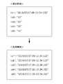
図3は、相対時刻を示すタイムスタンプに基づいて付与される、データの取得時刻を示すタイムスタンプの例を示す。 FIG. 3 shows an example of a time stamp indicating a data acquisition time, which is given based on a time stamp indicating a relative time.
製造装置20によって付与されたタイムスタンプに関し、先頭のデータ(d1)については、タイムスタンプが、データ(d1)の取得時刻、例えば“2019/07/17 09:12:34.123”となっており、データ(d2)〜(d5)については、タイムスタンプが、データ(d1)の取得時刻からの相対時刻である、“10”、“20”、“30”、“40”となっている。なお、これらの数字の単位はミリ秒である。 Regarding the time stamp given by the
そこで、データ集約部112は、データの取得時刻を示すタイムスタンプとして、データ(d1’)については、データ(d1)のタイムスタンプをそのまま用いる一方、データ(d2’)〜(d5’)については、データ(d1)の取得時刻を示すタイムスタンプに、各々、10ミリ秒、20ミリ秒、30ミリ秒、40ミリ秒を加算する。その結果、データ(d2’)に付与されるタイムスタンプは、“2019/07/17 09:12:34.133”となり、データ(d3’)に付与されるタイムスタンプは、“2019/07/17 09:12:34.143”となり、データ(d4’)に付与されるタイムスタンプは、“2019/07/17 09:12:34.153”となり、データ(d5’)に付与されるタイムスタンプは、“2019/07/17 09:12:34.163”となる。 Therefore, the
また、データ集約部112は、ストリーミングデータである散発的なデータの各々にタイムスタンプを付与する。このタイムスタンプは、散発的なデータの各々が、製造装置20において取得された時刻を示すタイムスタンプであってもよく、データ収集装置10によって受信された時刻を示すタイムスタンプであってもよい。 In addition, the
なお、データ集約部112は、タイムスタンプを付与した後の、個別の周期的なデータ及び散発的なデータを、後述の時系列データ保存部15に格納してもよい。 The
時系列データ整列部113は、周期的なデータに付与されたタイムスタンプと散発的なデータに付与されたタイムスタンプに基づいて、周期的なデータと散発的なデータとをまとめて整列させることにより、時系列データに変換する。 The time-series
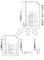
図4は、データ集約部112と時系列データ整列部113の機能を示す模式図である。図3の(a1)に示すように、複数の周期的なデータがひとまとめにされてバルク転送されるとする。なお、図3においては、例として、1つのバルクデータ(a1)に、3つの周期的なデータ(a1−1)〜(a1−3)が含まれるとする。
また、図4においては、散発的なデータとして、第1の散発的なデータ(b1)〜(b2)と、第2の散発的なデータ(c1)〜(c2)とがストリーミング転送されるとする。FIG. 4 is a schematic diagram showing the functions of the
Further, in FIG. 4, when the first sporadic data (b1) to (b2) and the second sporadic data (c1) to (c2) are stream-transferred as sporadic data. do.
データ集約部112は、バルクデータ(a1)を、個別の周期的なデータ(a1−1)〜(a1−3)に分解し、それぞれにタイムスタンプを付与する。また、データ集約部112は、第1の散発的なデータ(b1)〜(b2)の各々、及び第2の散発的なデータ(c1)〜(c2)の各々にタイムスタンプを付与する。 The
時系列データ整列部113は、周期的なデータ(a1−1)〜(a1−3)、第1の散発的なデータ(b1)〜(b2)、第2の散発的なデータ(c1)〜(c2)を、各々に付与されたタイムスタンプに基づいて、まとめて整列させることにより、時系列データに変換する。図4に示す例においては、時系列データ整列部113は、(a1−1)、(c1)、(b1)、(a1−2)、(c2)、(b2)、(a1−3)の順に整列させることで、時系列データに変換する。 The time-series
以下同様に、データ集約部112は、バルクデータ(a2)を、個別の周期的なデータ(a2−1)〜(a2−3)に分解し、それぞれにタイムスタンプを付与する。また、データ集約部112は、第1の散発的なデータ(b3)〜(b4)の各々、及び第2の散発的なデータ(c3)〜(c4)の各々にタイムスタンプを付与する。
時系列データ整列部113は、周期的なデータ(a2−1)〜(a2−3)、第1の散発的なデータ(b3)〜(b4)、第2の散発的なデータ(c3)〜(c4)を、各々に付与されたタイムスタンプに基づいて、まとめて整列させることにより、時系列データに変換する。すなわち、時系列データ整列部113は、図4に示す例においては、(a2−1)、(c3)、(b3)、(a2−2)、(c4)、(b4)、(a2−3)の順に整列させることで、時系列データに変換する。Similarly, the
The time-series
時系列データ送信部114は、時系列データをデータ収集装置10の外部に送信する。例えば、時系列データ送信部114は、縦軸又は横軸を時刻として時系列データを一覧表示する表示装置に、時系列データを送信することが可能である。 The time-series
時系列データ保存部15は、時系列データを保存する。なお、データ収集装置10は、時系列データ保存部15を必須の構成要素としなくてもよい。 The time-series
〔3 データ収集装置の動作〕
図5は、データ収集装置10の動作を示すフローチャートである。なお、ここではデータ収集装置10が第1データ収集部111aと第2データ収集部111bの2つのデータ収集部のみを備えているものとするが、これには限られない。
ステップS11において、第1データ収集部111aは、バルク転送されてきたバルクデータを収集する。[3 Operation of data collection device]
FIG. 5 is a flowchart showing the operation of the
In step S11, the first
ステップS12において、データ集約部112は、バルクデータを個別の周期的なデータに分解する。 In step S12, the
ステップS13において、データ集約部112は、個別の周期的なデータに対してタイムスタンプを付与する。 In step S13, the
ステップS21において、第2データ収集部111bは、ストリーミング転送されてきたストリーミングデータを収集する。 In step S21, the second
ステップS22において、データ集約部112は、ストリーミングデータである散発的なデータの各々にタイムスタンプを付与する。 In step S22, the
ステップS31において、時系列データ整列部113は、個別の周期的なデータと散発的なデータとを、各々に付与されたタイムスタンプに基づいて、時系列に従ってまとめて整列させることにより、時系列データに変換する。 In step S31, the time-series
ステップS32において、時系列データ保存部15は、時系列データを保存する。 In step S32, the time series
ステップS33において、時系列データ送信部114は、時系列データ保存部15に保存された時系列データを、データ収集装置10の外部装置、例えば表示装置に送信する。 In step S33, the time-series
なお、図5のフローチャートにおいて、ステップS11〜S13までの処理と、ステップS21〜S22までの処理はパラレルに実行されることが示されているが、これには限られない。例えば、ステップS11〜S13までの処理と、ステップS21〜S22までの処理をリニアに実行することが可能である。 In the flowchart of FIG. 5, it is shown that the processes of steps S11 to S13 and the processes of steps S21 to S22 are executed in parallel, but the present invention is not limited to this. For example, it is possible to linearly execute the processes of steps S11 to S13 and the processes of steps S21 to S22.
また、図5のフローチャートには、ステップS32として、時系列データを時系列データ保存部15に保存する処理が示されているが、これには限られない。例えば、ステップS32を省略し、時系列データ整列部113によって、個別の周期的なデータと散発的なデータとを時系列データに変換し、変換した時系列データを時系列データ保存部15に保存することがないまま、時系列データ送信部114が時系列データを、データ収集装置10の外部装置に送信してもよい。 Further, in the flowchart of FIG. 5, a process of storing the time series data in the time series
〔4 具体例〕
図6A及び図6Bは、データ収集装置10の動作の具体例を示す図である。
データ(A)は、第1データ収集部111aによって収集されるバルクデータに含まれる周期的なデータの例である。図6Aに示す例においては、データ(A)は、主軸の振動を示す位置データ、クーラントのON/OFFを示すデータ、主軸の回転のON/OFFを示すデータを含み、各々に付与された、初回のデータ取得時刻からの相対時刻を示すタイムスタンプと共に、製造装置20から第1データ収集部111aにバルク転送される。[4 Specific example]
6A and 6B are diagrams showing specific examples of the operation of the
The data (A) is an example of periodic data included in the bulk data collected by the first
データ(B)は、第2データ収集部111bによって収集される、第1の散発的なデータの例である。図6Aに示す例においては、データ(B)は、主軸温度の変化分を示すデータであり、タイムスタンプが付与されることなく、製造装置20から第2データ収集部111bにストリーミング転送される。 The data (B) is an example of the first sporadic data collected by the second
データ(C)は、第3データ収集部111cによって収集される、第2の散発的なデータの例である。図6Aに示す例においては、データ(C)は、主軸温度が所定範囲を超えたこと、又は下回ったことを報知する警告を示すデータであり、タイムスタンプが付与されることなく、製造装置20から第3データ収集部111cにストリーミング転送される。 Data (C) is an example of second sporadic data collected by the third data collection unit 111c. In the example shown in FIG. 6A, the data (C) is data indicating a warning that the spindle temperature has exceeded or has fallen below a predetermined range, and the
データ集約部112は、データ(A)を個別の周期的なデータに分解すると共に、個別のデータに対し、製造装置20において各々のデータに付与された相対時刻を示すタイムスタンプを用いて、製造装置20において各々のデータが取得された取得時刻自体を示すタイムスタンプを付与する。 The
更に、データ集約部112は、データ(B)及びデータ(C)に対し、データ収集装置10における受信時刻を示すタイムスタンプを付与する。 Further, the
時系列データ整列部113は、個別の周期的なデータ及び散発的なデータを、タイムスタンプに基づいてまとめて整列することにより、時系列データであるデータ(D)に変換する。図6Aに示す例においては、散発的なデータ(B)及びデータ(C)は、それらの収集時刻が、データ(A)に含まれていた個別の周期的なデータの取得時刻と一致する箇所に挿入されるが、これには限られない。例えば、散発的なデータ(B)及びデータ(C)の収集時刻が、連続する2つの周期的なデータの取得時刻の中間にある場合には、散発的なデータ(B)及びデータ(C)は、これら連続する2つの周期的なデータの間に挿入してもよい。 The time-series
時系列データ送信部114は、時系列データであるデータ(D)を、データ収集装置10の外部装置に送信する。図6Bに示す例においては、時系列データ送信部114がデータ(D)を、データ収集装置10の外部に存在する表示装置に送信する。その結果、図6Bに示すように、当該表示装置において、時刻を横軸とした上で、周期的なデータである、振動を示す位置データ、クーラントのON/OFFを示すデータ、及び主軸の回転のON/OFFを示すデータと、散発的なデータである、主軸温度を示すデータ、及び温度警告を示すデータとが一覧表示される。 The time-series
〔5 実施形態が奏する効果〕
本実施形態に係るデータ収集装置10は、周期的に取得されたデータが複数個ひとまとめにされてバルク転送されたバルクデータを受信する第1データ収集部111aと、散発的に取得されたデータがその都度ストリーミング転送されたストリーミングデータを受信する第2データ収集部111bと、まとめて受信されたバルクデータに含まれる複数のデータを個別のデータに分解して、周期的な個別のデータの各々にタイムスタンプを付与すると共に、ストリーミングデータである散発的なデータの各々にタイムスタンプを付与するデータ集約部112と、周期的な個別のデータ及び散発的なデータを、タイムスタンプに基づいてまとめて整列させることにより、時系列データに変換する時系列データ整列部113と、を備える。[5 Effects of the embodiment]
In the
これにより、製造装置において周期的に発生するデータをひとまとめにして送信するバルク転送のデータと、散発的に発生するデータをその都度送信するストリーミング転送のデータとを有する複数の種類のデータを集約することが可能となる。
更に、製造装置から収集したバルクデータとストリーミングデータとがタイムスタンプに基づいて整列された時系列データとなることにより、縦軸又は横軸を時刻としてリアルタイムにセンサデータを描き出して監視用途に使用したり、あるいは、一定時間内の各種センサ値の相関を調べるような分析をしたりすることが容易になる。As a result, a plurality of types of data including bulk transfer data in which data generated periodically in the manufacturing apparatus are collectively transmitted and data in streaming transfer in which data generated sporadically are transmitted each time are aggregated. It becomes possible.
Furthermore, the bulk data and streaming data collected from the manufacturing equipment become time-series data arranged based on the time stamp, so that the sensor data can be drawn out in real time with the vertical or horizontal axis as the time and used for monitoring purposes. Alternatively, it becomes easy to perform an analysis such as examining the correlation between various sensor values within a certain period of time.
また、データ収集装置10において、バルクデータに含まれる周期的に取得されたデータに付与されるタイムスタンプは、製造装置において取得された時刻のタイムスタンプである。 Further, in the
これにより、データの収集元である製造装置における動作状況を把握する上で、有用なタイムスタンプに基づいてデータを集約することが可能となる。 This makes it possible to aggregate data based on a time stamp that is useful for grasping the operating status of the manufacturing apparatus that is the data collection source.
また、データ収集装置10において、ストリーミングデータとしての散発的に取得されたデータに付与されるタイムスタンプは、製造装置において取得された時刻のタイムスタンプである。 Further, in the
これにより、データの収集元である製造装置における動作状況を把握する上で、有用なタイムスタンプに基づいてデータを集約することが可能となる。 This makes it possible to aggregate data based on a time stamp that is useful for grasping the operating status of the manufacturing apparatus that is the data collection source.
また、データ収集装置10において、ストリーミングデータとしての散発的に取得されたデータに付与されるタイムスタンプは、データ収集装置10において受信された時刻のタイムスタンプである。 Further, the time stamp given to the data sporadically acquired as streaming data in the
これにより、製造装置の側で散発的なデータにタイムスタンプが付与されなかった場合にも、バルクデータとストリーミングデータとを時系列に従って整列させ、集約することが可能となる。 As a result, even if the sporadic data is not time-stamped on the manufacturing apparatus side, the bulk data and the streaming data can be aligned and aggregated in chronological order.
また、データ収集装置10は、時系列データを表示する表示装置に、時系列データを送信する時系列データ送信部114を更に備える。 Further, the
これにより、時系列データとして集約されたバルクデータとストリーミングデータとを、一覧表示することが可能となる。 This makes it possible to display a list of bulk data and streaming data aggregated as time series data.
また、データ収集装置10は、時系列データを保存する時系列データ保存部115を更に備える。 In addition, the
これにより、データ収集装置10は、バルクデータとストリーミングデータとを時系列データに変換した直後に、外部装置に送信する必要がない場合に、時系列データを一時保存しておくことが可能となる。 As a result, the
上記のデータ収集装置10及びデータ収集システム1に含まれる各構成部は、ハードウェア、ソフトウェア又はこれらの組み合わせにより実現することができる。また、上記のデータ収集装置10及びデータ収集システム1に含まれる各構成部のそれぞれの協働により行なわれるデータ収集方法も、ハードウェア、ソフトウェア又はこれらの組み合わせにより実現することができる。ここで、ソフトウェアによって実現されるとは、コンピュータがプログラムを読み込んで実行することにより実現されることを意味する。 Each component included in the
プログラムは、様々なタイプの非一時的なコンピュータ可読媒体(non-transitory computer readable medium)を用いて格納され、コンピュータに供給することができる。非一時的なコンピュータ可読媒体は、様々なタイプの実体のある記録媒体(tangible storage medium)を含む。非一時的なコンピュータ可読媒体の例は、磁気記録媒体(例えば、フレキシブルディスク、磁気テープ、ハードディスクドライブ)、光磁気記録媒体(例えば、光磁気ディスク)、CD−ROM(Read Only Memory)、CD−R、CD−R/W、半導体メモリ(例えば、マスクROM、PROM(Programmable ROM)、EPROM(Erasable PROM)、フラッシュROM、RAM(random access memory))を含む。また、プログラムは、様々なタイプの一時的なコンピュータ可読媒体(transitory computer readable medium)によってコンピュータに供給されてもよい。一時的なコンピュータ可読媒体の例は、電気信号、光信号、及び電磁波を含む。一時的なコンピュータ可読媒体は、電線及び光ファイバ等の有線通信路、又は無線通信路を介して、プログラムをコンピュータに供給できる。 Programs can be stored and supplied to a computer using various types of non-transitory computer readable medium. Non-temporary computer-readable media include various types of tangible storage media. Examples of non-temporary computer-readable media include magnetic recording media (eg, flexible disks, magnetic tapes, hard disk drives), magneto-optical recording media (eg, magneto-optical disks), CD-ROMs (Read Only Memory), CD- R, CD-R / W, semiconductor memory (for example, mask ROM, PROM (Programmable ROM), EPROM (Erasable PROM), flash ROM, RAM (random access memory)) are included. The program may also be supplied to the computer by various types of transitory computer readable medium. Examples of temporary computer-readable media include electrical, optical, and electromagnetic waves. The temporary computer-readable medium can supply the program to the computer via a wired communication path such as an electric wire and an optical fiber, or a wireless communication path.
1 データ収集システム
10 データ収集装置
11 制御部
15 時系列データ保存部
20 製造装置
21 数値制御装置
22 工作機械
23 センサ
24 状態監視機器
111a 第1データ収集部
111b 第2データ収集部
111n 第nデータ収集部
112 データ集約部
113 時系列データ整列部
114 時系列データ送信部
1
Claims (6)
Translated fromJapanese前記製造装置によって散発的に取得された第2データがその都度ストリーミング転送される、ストリーミングデータを受信する第2データ収集部と、
前記第1データ収集部により受信された前記バルクデータに含まれる、それぞれ周期的に取得された複数個の第1データを周期毎に取得された第1データに分解して、前記周期毎の第1データの各々にタイムスタンプを付与すると共に、前記第2データの各々にタイムスタンプを付与するデータ集約部と、
前記第1データ及び前記第2データを、前記タイムスタンプに基づいて整列させることにより、時系列データに変換する時系列データ整列部と、
を備えるデータ収集装置。Periodicallythe firstdata generatedis obtained by the manufacturingapparatus, the first data obtainedaretransmitted with a plurality collectively has beenbulk data, the first data acquisition unit for receivingthe bulk data When,
A second data collection unit that receives streaming data, in which the second data sporadically acquired by the manufacturing apparatus is stream-transferred each time,
The firstsaid receivedby the data acquisition unit included in the bulkdata, the first data of a pluralitypieceswhich are periodically acquired each decomposed intofirst data obtained in each cycle, firstof each of theperiods A data aggregation unit that assigns a time stamp to each of the 1 data and also assigns a time stamp to each of the second data.
A time-series data aligning unit that converts the first data and the second data into time-series data by aligning them based on the time stamp.
A data acquisition device equipped with.
Priority Applications (4)
| Application Number | Priority Date | Filing Date | Title |
|---|---|---|---|
| JP2018231063AJP6927951B2 (en) | 2018-12-10 | 2018-12-10 | Manufacturing equipment data collection equipment |
| DE102019218146.5ADE102019218146A1 (en) | 2018-12-10 | 2019-11-25 | DATA COLLECTING DEVICE FOR MANUFACTURING DEVICE |
| US16/701,617US20200183375A1 (en) | 2018-12-10 | 2019-12-03 | Data collection device for manufacturing device |
| CN201911241886.8ACN111290333B (en) | 2018-12-10 | 2019-12-06 | Data collection device for manufacturing device |
Applications Claiming Priority (1)
| Application Number | Priority Date | Filing Date | Title |
|---|---|---|---|
| JP2018231063AJP6927951B2 (en) | 2018-12-10 | 2018-12-10 | Manufacturing equipment data collection equipment |
Publications (2)
| Publication Number | Publication Date |
|---|---|
| JP2020095343A JP2020095343A (en) | 2020-06-18 |
| JP6927951B2true JP6927951B2 (en) | 2021-09-01 |
Family
ID=70776517
Family Applications (1)
| Application Number | Title | Priority Date | Filing Date |
|---|---|---|---|
| JP2018231063AActiveJP6927951B2 (en) | 2018-12-10 | 2018-12-10 | Manufacturing equipment data collection equipment |
Country Status (4)
| Country | Link |
|---|---|
| US (1) | US20200183375A1 (en) |
| JP (1) | JP6927951B2 (en) |
| CN (1) | CN111290333B (en) |
| DE (1) | DE102019218146A1 (en) |
Families Citing this family (4)
| Publication number | Priority date | Publication date | Assignee | Title |
|---|---|---|---|---|
| EP4068023A4 (en)* | 2019-11-27 | 2023-08-09 | Kabushiki Kaisha Yaskawa Denki | DEVICE AND METHOD FOR COLLECTING PRODUCTION SYSTEM INFORMATION, AND ASSOCIATED PROGRAM |
| DE102019135483A1 (en)* | 2019-12-20 | 2021-06-24 | Trumpf Werkzeugmaschinen Gmbh + Co. Kg | Early detection and reaction to errors in a machine |
| JP7579152B2 (en) | 2021-01-13 | 2024-11-07 | 株式会社荏原製作所 | Data management method for semiconductor manufacturing equipment and control device equipped with ring buffer |
| CN114140993A (en)* | 2021-10-19 | 2022-03-04 | 安徽中科昊音智能科技有限公司 | Steel mill mould voiceprint monitoring system |
Family Cites Families (9)
| Publication number | Priority date | Publication date | Assignee | Title |
|---|---|---|---|---|
| US7047142B2 (en) | 2001-02-23 | 2006-05-16 | Arkray, Inc. | Monitoring apparatus and monitoring object apparatus |
| US9565275B2 (en)* | 2012-02-09 | 2017-02-07 | Rockwell Automation Technologies, Inc. | Transformation of industrial data into useful cloud information |
| US7328130B2 (en)* | 2005-08-17 | 2008-02-05 | Xtek, Inc. | Data acquisition system for system monitoring |
| JP2008204166A (en)* | 2007-02-20 | 2008-09-04 | Mitsubishi Electric Corp | Plant monitoring and control system |
| US8688622B2 (en)* | 2008-06-02 | 2014-04-01 | The Boeing Company | Methods and systems for loading data into a temporal data warehouse |
| US10909137B2 (en)* | 2014-10-06 | 2021-02-02 | Fisher-Rosemount Systems, Inc. | Streaming data for analytics in process control systems |
| US10649419B2 (en)* | 2016-06-14 | 2020-05-12 | Johnson Controls Technology Company | Building management system with virtual points and optimized data integration |
| CN108803502B (en)* | 2017-04-27 | 2022-07-26 | 横河电机株式会社 | Data collection device and system, data server, data collection method, and computer-readable non-volatile recording medium |
| US10553044B2 (en)* | 2018-01-31 | 2020-02-04 | Mentor Graphics Development (Deutschland) Gmbh | Self-diagnosis of faults with a secondary system in an autonomous driving system |
- 2018
- 2018-12-10JPJP2018231063Apatent/JP6927951B2/enactiveActive
- 2019
- 2019-11-25DEDE102019218146.5Apatent/DE102019218146A1/enactivePending
- 2019-12-03USUS16/701,617patent/US20200183375A1/ennot_activeAbandoned
- 2019-12-06CNCN201911241886.8Apatent/CN111290333B/enactiveActive
Also Published As
| Publication number | Publication date |
|---|---|
| US20200183375A1 (en) | 2020-06-11 |
| CN111290333A (en) | 2020-06-16 |
| JP2020095343A (en) | 2020-06-18 |
| CN111290333B (en) | 2024-02-23 |
| DE102019218146A1 (en) | 2020-06-10 |
Similar Documents
| Publication | Publication Date | Title |
|---|---|---|
| JP6927951B2 (en) | Manufacturing equipment data collection equipment | |
| CN108255131B (en) | The method in the service life of lathe, production management system and prediction and/or detection instrument | |
| KR102334965B1 (en) | Predictive maintenance system for efficient management of factory automation equipment and productivity improvement | |
| JP6404893B2 (en) | Tool life estimation device | |
| TWI618018B (en) | Production mangement method and system of utilizing power consumption feature | |
| CN105631577B (en) | Data transmission method, analysis and prediction report method and system for robot | |
| CN112262017B (en) | Machining dimension prediction device, system, and method for machine tool, device abnormality determination device for machine tool, and recording medium | |
| CN101334656B (en) | A CNC machine tool processing performance monitoring system | |
| KR20190137783A (en) | Data interface device for use on numerically controlled machine tools | |
| CN103823409A (en) | Numerical machine tool machining state multi-parameter online active monitoring system and implement method thereof | |
| CN108459568B (en) | Data collection device and computer readable medium | |
| JP6730441B2 (en) | Data storage device and system | |
| CN106056263A (en) | Machine tool management system | |
| JP6966166B2 (en) | Machine tool feed shaft operating status display device and operating status display method | |
| KR101855679B1 (en) | Remote real monitoring and prediction system of auto-machine tool | |
| US20060089742A1 (en) | System and method for monitoring machine health | |
| US7409261B2 (en) | Data management and networking system and method | |
| Denkena et al. | Augmenting milling process data for shape error prediction | |
| KR102523198B1 (en) | processing system and method for cutter damage sensing and change time using external device | |
| KR102045617B1 (en) | Monitoring apparatus and method for abnormal of equipments | |
| JP4958936B2 (en) | Air conditioning system diagnostic device | |
| JP2020163493A (en) | Tool replacement timing management system | |
| KR20230059950A (en) | Integrated estimation model for cutting force and tool wear | |
| CN109507958B (en) | Data collection device, data transmission device, data collection system, and computer-readable medium | |
| US20220317664A1 (en) | Early detection of and response to faults in a machine |
Legal Events
| Date | Code | Title | Description |
|---|---|---|---|
| A621 | Written request for application examination | Free format text:JAPANESE INTERMEDIATE CODE: A621 Effective date:20200513 | |
| A131 | Notification of reasons for refusal | Free format text:JAPANESE INTERMEDIATE CODE: A131 Effective date:20210323 | |
| A521 | Request for written amendment filed | Free format text:JAPANESE INTERMEDIATE CODE: A523 Effective date:20210414 | |
| TRDD | Decision of grant or rejection written | ||
| A01 | Written decision to grant a patent or to grant a registration (utility model) | Free format text:JAPANESE INTERMEDIATE CODE: A01 Effective date:20210706 | |
| A61 | First payment of annual fees (during grant procedure) | Free format text:JAPANESE INTERMEDIATE CODE: A61 Effective date:20210805 | |
| R150 | Certificate of patent or registration of utility model | Ref document number:6927951 Country of ref document:JP Free format text:JAPANESE INTERMEDIATE CODE: R150 |