JP6927650B2 - Compact robot wrist - Google Patents
Compact robot wristDownload PDFInfo
- Publication number
- JP6927650B2 JP6927650B2JP2020008040AJP2020008040AJP6927650B2JP 6927650 B2JP6927650 B2JP 6927650B2JP 2020008040 AJP2020008040 AJP 2020008040AJP 2020008040 AJP2020008040 AJP 2020008040AJP 6927650 B2JP6927650 B2JP 6927650B2
- Authority
- JP
- Japan
- Prior art keywords
- pulleys
- cable
- tool
- pulley
- cables
- Prior art date
- Legal status (The legal status is an assumption and is not a legal conclusion. Google has not performed a legal analysis and makes no representation as to the accuracy of the status listed.)
- Active
Links
Images


Classifications
- A—HUMAN NECESSITIES
- A61—MEDICAL OR VETERINARY SCIENCE; HYGIENE
- A61B—DIAGNOSIS; SURGERY; IDENTIFICATION
- A61B34/00—Computer-aided surgery; Manipulators or robots specially adapted for use in surgery
- A61B34/70—Manipulators specially adapted for use in surgery
- A61B34/71—Manipulators operated by drive cable mechanisms
- B—PERFORMING OPERATIONS; TRANSPORTING
- B25—HAND TOOLS; PORTABLE POWER-DRIVEN TOOLS; MANIPULATORS
- B25J—MANIPULATORS; CHAMBERS PROVIDED WITH MANIPULATION DEVICES
- B25J17/00—Joints
- B25J17/02—Wrist joints
- A—HUMAN NECESSITIES
- A61—MEDICAL OR VETERINARY SCIENCE; HYGIENE
- A61B—DIAGNOSIS; SURGERY; IDENTIFICATION
- A61B17/00—Surgical instruments, devices or methods
- A61B17/28—Surgical forceps
- A61B17/29—Forceps for use in minimally invasive surgery
- A—HUMAN NECESSITIES
- A61—MEDICAL OR VETERINARY SCIENCE; HYGIENE
- A61B—DIAGNOSIS; SURGERY; IDENTIFICATION
- A61B34/00—Computer-aided surgery; Manipulators or robots specially adapted for use in surgery
- A61B34/30—Surgical robots
- B—PERFORMING OPERATIONS; TRANSPORTING
- B25—HAND TOOLS; PORTABLE POWER-DRIVEN TOOLS; MANIPULATORS
- B25J—MANIPULATORS; CHAMBERS PROVIDED WITH MANIPULATION DEVICES
- B25J15/00—Gripping heads and other end effectors
- B25J15/0028—Gripping heads and other end effectors with movable, e.g. pivoting gripping jaw surfaces
- B—PERFORMING OPERATIONS; TRANSPORTING
- B25—HAND TOOLS; PORTABLE POWER-DRIVEN TOOLS; MANIPULATORS
- B25J—MANIPULATORS; CHAMBERS PROVIDED WITH MANIPULATION DEVICES
- B25J15/00—Gripping heads and other end effectors
- B25J15/02—Gripping heads and other end effectors servo-actuated
- B25J15/0253—Gripping heads and other end effectors servo-actuated comprising parallel grippers
- B25J15/0286—Gripping heads and other end effectors servo-actuated comprising parallel grippers actuated by chains, cables or ribbons
- A—HUMAN NECESSITIES
- A61—MEDICAL OR VETERINARY SCIENCE; HYGIENE
- A61B—DIAGNOSIS; SURGERY; IDENTIFICATION
- A61B17/00—Surgical instruments, devices or methods
- A61B17/28—Surgical forceps
- A61B17/29—Forceps for use in minimally invasive surgery
- A61B2017/2926—Details of heads or jaws
- A61B2017/2932—Transmission of forces to jaw members
- A61B2017/2938—Independently actuatable jaw members, e.g. two actuating rods
- A—HUMAN NECESSITIES
- A61—MEDICAL OR VETERINARY SCIENCE; HYGIENE
- A61B—DIAGNOSIS; SURGERY; IDENTIFICATION
- A61B34/00—Computer-aided surgery; Manipulators or robots specially adapted for use in surgery
- A61B34/30—Surgical robots
- A61B2034/305—Details of wrist mechanisms at distal ends of robotic arms
- A61B2034/306—Wrists with multiple vertebrae
- A—HUMAN NECESSITIES
- A61—MEDICAL OR VETERINARY SCIENCE; HYGIENE
- A61B—DIAGNOSIS; SURGERY; IDENTIFICATION
- A61B34/00—Computer-aided surgery; Manipulators or robots specially adapted for use in surgery
- A61B34/70—Manipulators specially adapted for use in surgery
- A61B34/71—Manipulators operated by drive cable mechanisms
- A61B2034/715—Cable tensioning mechanisms for removing slack
- Y—GENERAL TAGGING OF NEW TECHNOLOGICAL DEVELOPMENTS; GENERAL TAGGING OF CROSS-SECTIONAL TECHNOLOGIES SPANNING OVER SEVERAL SECTIONS OF THE IPC; TECHNICAL SUBJECTS COVERED BY FORMER USPC CROSS-REFERENCE ART COLLECTIONS [XRACs] AND DIGESTS
- Y10—TECHNICAL SUBJECTS COVERED BY FORMER USPC
- Y10S—TECHNICAL SUBJECTS COVERED BY FORMER USPC CROSS-REFERENCE ART COLLECTIONS [XRACs] AND DIGESTS
- Y10S901/00—Robots
- Y10S901/27—Arm part
- Y10S901/28—Joint
- Y10S901/29—Wrist
- Y—GENERAL TAGGING OF NEW TECHNOLOGICAL DEVELOPMENTS; GENERAL TAGGING OF CROSS-SECTIONAL TECHNOLOGIES SPANNING OVER SEVERAL SECTIONS OF THE IPC; TECHNICAL SUBJECTS COVERED BY FORMER USPC CROSS-REFERENCE ART COLLECTIONS [XRACs] AND DIGESTS
- Y10—TECHNICAL SUBJECTS COVERED BY FORMER USPC
- Y10S—TECHNICAL SUBJECTS COVERED BY FORMER USPC CROSS-REFERENCE ART COLLECTIONS [XRACs] AND DIGESTS
- Y10S901/00—Robots
- Y10S901/30—End effector
- Y10S901/31—Gripping jaw
- Y10S901/36—Actuating means
- Y10S901/38—Electric motor
Landscapes
- Health & Medical Sciences (AREA)
- Engineering & Computer Science (AREA)
- Life Sciences & Earth Sciences (AREA)
- Surgery (AREA)
- Robotics (AREA)
- Medical Informatics (AREA)
- Biomedical Technology (AREA)
- Heart & Thoracic Surgery (AREA)
- Nuclear Medicine, Radiotherapy & Molecular Imaging (AREA)
- Molecular Biology (AREA)
- Animal Behavior & Ethology (AREA)
- General Health & Medical Sciences (AREA)
- Public Health (AREA)
- Veterinary Medicine (AREA)
- Mechanical Engineering (AREA)
- Ophthalmology & Optometry (AREA)
- Manipulator (AREA)
- Surgical Instruments (AREA)
Description
Translated fromJapanese [関連出願の相互参照]
本出願は、合衆国法典第35巻第119条(e)項の下で、2013年3月14日に出願された米国仮特許出願第61/781092号、および2013年3月15日に出願された米国仮特許出願第61/791248号の優先権利益を主張し、これらの仮出願は、参照することによりその全体が本出願に組み込まれ、本明細書の一部と見なすものとする。[Cross-reference of related applications]
This application is filed under US Code, Vol. 35, Section 119 (e), US Provisional Patent Application No. 61/781092, filed March 14, 2013, and March 15, 2013. Claiming the priority interests of US Provisional Patent Application No. 61/791248, these provisional applications shall be incorporated herein by reference in their entirety and shall be deemed part of this specification.
[背景]
[分野]
ロボットのエンドエフェクタは、ロボットが対象体を操作することを可能にする。本出願は、ロボットツール、該ツールのエンドエフェクタ、およびそれらを動作させる方法に関する。[background]
[Field]
The robot's end effector allows the robot to manipulate the object. The present application relates to robot tools, end effectors of the tools, and methods of operating them.
[関連出願の説明]
ロボットは、工業、研究、医療、および医療外用途を含め、様々な用途に使われる。それぞれの異なる種類のロボットは、ほとんどのロボットの間に共通な特徴および特性に加え、それ自体の独自の特徴および特性のセットを有し得る。ほとんどのロボットに共通な1つの特性は、ツールの使用である。ロボットに制御されるツールは、様々なタスクを実施するために使われる。ロボットに制御される各ツールは、実施対象のタスクのために特別に設計され得る。通常、ロボットのツールは、細長い形状で、エンドエフェクタ(例えば、捕捉具(grasper))を有する。[Explanation of related applications]
Robots are used in a variety of applications, including industrial, research, medical, and non-medical applications. Each different type of robot may have its own unique set of features and characteristics, in addition to the characteristics and characteristics common to most robots. One characteristic common to most robots is the use of tools. Tools controlled by robots are used to perform various tasks. Each robot-controlled tool can be specially designed for the task to be performed. Robot tools are typically elongated in shape and have end effectors (eg, graspers).
手術システムに関しては、典型的な市販のロボットシステムは、ケーブルまたは他のメカニズムで制御される真っすぐな剛体のツールまたは柔軟性のツール(例えば、湾曲ツール)を用いている。真っすぐな剛体ツールは、一部の手術状況では、例えば、切開点または進入口(例えば、ツールが身体に入る箇所)と手術対象の組織との間に臓器または解剖構造体がある場合には、真っすぐなシャフトが当該組織にアクセスするためにその臓器または解剖構造体に迂回して到達することができないので、不適当である。真っすぐな剛性ツールの別の欠点は、患者に対する外傷を制限するため場合によって望まれる、単一の手術切開部または進入口を通して複数のツールが導入される単孔式手術と言われる手術への使用には適さないことである。かかる単孔式手術において、縫合などのタスクのためには、複数のツールの間での協働的相互作用が必要となる。協働的に相互作用するには、これらのツールは、相異なる角度から手術野に集中する必要があり、真っすぐな剛性ツールは、これにうまく適さない。 With respect to surgical systems, typical off-the-shelf robotic systems use straight rigid or flexible tools (eg, curved tools) controlled by cables or other mechanisms. Straight rigid tools are available in some surgical situations, for example, if there is an organ or anatomical structure between the incision or entrance (eg, where the tool enters the body) and the tissue to be operated on. It is inappropriate because a straight shaft cannot bypass and reach the organ or anatomical structure to access the tissue. Another drawback of straight stiffness tools is their use in so-called monotreme surgery, where multiple tools are introduced through a single surgical incision or entrance, which is sometimes desired to limit trauma to the patient. It is not suitable for. In such single-hole surgery, tasks such as suturing require collaborative interactions between multiple tools. To interact collaboratively, these tools need to focus on the surgical field from different angles, and straight rigid tools are not well suited for this.
湾曲性または屈曲性ツールなどの柔軟性ツールについては、これらのツールは、前述の真っすぐな剛性ツールのアクセス性および操作性上の問題の一部は克服するが、これらにも欠点がある。柔軟性ツールの短所の1つは、通常、これらには外科手術の間における曲げ負荷に耐えるのに十分な剛性がないことである。一般に、剛性を向上するため、これらツールの湾曲または屈曲プロフィールは、製造者もしくは屈曲ツールを使用するユーザによって人体の外部で事前形成され、したがって体内の現位置で手術体形状に合わせて曲げられることができない。セグメント分けされたまたは柔軟なシャフトを有する他の柔軟性ツールが利用可能であり、これらは、例えばケーブルによって制御されることができる。これらの柔軟性ツールも、外科手術の間にいったん曲げられると、曲げ負荷に耐えるのに十分な剛性を達成することができないなどといった短所を有する。 For flexible tools such as curving or flexing tools, these tools overcome some of the accessibility and maneuverability issues of the straight stiff tools described above, but they also have drawbacks. One of the disadvantages of flexibility tools is that they are usually not rigid enough to withstand bending loads during surgery. Generally, to improve stiffness, the curvature or flexion profile of these tools should be preformed outside the human body by the manufacturer or the user using the flexion tool, and thus bent to fit the surgical body shape at its current location within the body. I can't. Other flexibility tools with segmented or flexible shafts are available, which can be controlled, for example, by cables. These flexible tools also have the disadvantage that once bent during surgery, they cannot achieve sufficient rigidity to withstand the bending load.
また、真っすぐな剛性ツールおよび湾曲性または屈曲性ツールは、非医療応用にも使われており、前記非医療応用に使われるとき前述したのと同様な欠点を有する。 Straight rigid tools and curving or flexing tools are also used in non-medical applications and have the same drawbacks as described above when used in said non-medical applications.
上記から、市販のツールについて前述した欠点に対処した改良ロボットツールおよびエンドエフェクタが必要とされている。現在市販されているものに比べ、作業箇所のよりわずかな閉塞、複雑な手術を遂行するための向上された能力、およびアクセスが制限される領域で作業するための向上された能力を備えた、改良されたロボットツールおよびエンドエフェクタが必要とされている。 From the above, there is a need for improved robot tools and end effectors that address the above-mentioned drawbacks of commercially available tools. With less obstruction of the work area, improved ability to perform complex surgery, and improved ability to work in areas with restricted access, compared to those currently on the market. Improved robot tools and end effectors are needed.
本発明の一態様によれば、エンドエフェクタに連結された手首部(wrist)を備えたツールが提供される。この手首部は、4つの独立したケーブル端を含むことができる。これら4つの独立したケーブル端は、各々の独立したケーブル端が別々に駆動されてもよいように配置(arrange)されることができる。一実施形態において、これら4つの独立したケーブル端は、4本の独立したケーブルによって定義される。別の実施形態において、この4つの独立したケーブル端は、2つのケーブルによって定義され、各ケーブルの各端は、独立したケーブル端を定義する。 According to one aspect of the invention, a tool with a wrist connected to an end effector is provided. This wrist can include four independent cable ends. These four independent cable ends can be arranged so that each independent cable end may be driven separately. In one embodiment, these four independent cable ends are defined by four independent cables. In another embodiment, the four independent cable ends are defined by two cables, and each end of each cable defines an independent cable end.
一実施形態において、本ツールは、各ケーブル端を別々に制御するための4つのモータを含むようにアレンジされることができる。 In one embodiment, the tool can be arranged to include four motors for controlling each cable end separately.
本発明の一態様によれば、エンドエフェクタに連結された手首部を有するツールは、ケーブルの代わりに1本以上の撚り紐を有することができる。単一の紐は、撚り紐のように機能するようアレンジされてもよい。本ツールは、エンドエフェクタを駆動する1本以上の撚り紐を有することができる。 According to one aspect of the invention, a tool with a wrist attached to an end effector can have one or more twisted cords instead of a cable. A single string may be arranged to act like a twisted string. The tool can have one or more strands that drive the end effector.
手首部およびエンドエフェクタを備える本ツールは、プーリの3つ以上のセットを有するようにアレンジされることができる。各ケーブルは、各ケーブルが2つの直交する方向でプーリの3つ以上のセットに巻き付くように配置されることができる。各ケーブルは、各ケーブルの2つの側の間の相対的な張力がヨー運動をもたらすことができるように配置されることができる。各ケーブルは、2つのケーブルの間の相対的な張力がピッチ運動をもたらすことができるように配置されることができる。 The tool, which includes a wrist and end effector, can be arranged to have three or more sets of pulleys. Each cable can be arranged such that each cable wraps around three or more sets of pulleys in two orthogonal directions. Each cable can be arranged so that the relative tension between the two sides of each cable can result in yaw motion. Each cable can be arranged so that the relative tension between the two cables can result in pitch motion.
手首部およびエンドエフェクタを備える本ツールは、プーリの3つのセットとプーリの2つの追加セットとを有するようにアレンジされることができる。各ケーブルは、各ケーブルが2つの直交する方向で該プーリの3つのセットに巻き付くように配置されることができる。プーリの2つの追加セットは、プーリの3つのセットに対して角度を付けることができる。プーリの2つの追加セットは、プーリの3つのセットの間に配置されることができる。 The tool, which includes a wrist and end effector, can be arranged to have three sets of pulleys and two additional sets of pulleys. Each cable can be arranged such that each cable wraps around three sets of said pulleys in two orthogonal directions. The two additional sets of pulleys can be angled with respect to the three sets of pulleys. Two additional sets of pulleys can be placed between the three sets of pulleys.
本発明の一態様によれば、プーリの3つのセットが設けられ、プーリの3つの追加セットが設けられる。各ケーブルは、各ケーブルが2つの直交する方向でプーリの3つのセットに巻き付くように配置されることができる。プーリの該3つの追加セットは、プーリの3つのセットの間に配置されることができる。プーリの2つのセットおよびプーリの2つの追加セットは、第1の方向に配置することができ、プーリの1つのセットおよびプーリの1つの追加セットは、第1の方向と直行する方向に配置されることができる。 According to one aspect of the invention, three sets of pulleys are provided and three additional sets of pulleys are provided. Each cable can be arranged such that each cable wraps around three sets of pulleys in two orthogonal directions. The three additional sets of pulleys can be placed between the three sets of pulleys. Two sets of pulleys and two additional sets of pulleys can be placed in the first direction, one set of pulleys and one additional set of pulleys are placed in a direction orthogonal to the first direction. Can be done.
本発明の一態様によれば、プーリの3つのセットが設けられ、プーリの2つの追加セットが設けられる。各ケーブルは、各ケーブルが2つの直交する方向でプーリの3つ以上のセットに巻き付くように配置されることができる。プーリの2つの追加セットは、プーリの3つのセットの間に配置されることができる。プーリの2つのセットおよびプーリの2つの追加セットは、第1の方向に配置されることができ、プーリの1つのセットは、第1の方向に直交する方向に配置されることができる。 According to one aspect of the invention, three sets of pulleys are provided and two additional sets of pulleys are provided. Each cable can be arranged such that each cable wraps around three or more sets of pulleys in two orthogonal directions. Two additional sets of pulleys can be placed between the three sets of pulleys. Two sets of pulleys and two additional sets of pulleys can be arranged in a first direction and one set of pulleys can be arranged in a direction orthogonal to the first direction.
本ツールは、2つのケーブルループが3つのモータで制御されるように配置されることができる。第3モータは、メカニズムを制御するように配置されることができる。このメカニズムは、該メカニズムが同じケーブルの両側に張力を加えるように配置されることができる。このメカニズムは、該メカニズムがピッチ運動を可能にするように配置されることができる。 The tool can be arranged so that two cable loops are controlled by three motors. The third motor can be arranged to control the mechanism. This mechanism can be arranged such that the mechanism applies tension to both sides of the same cable. This mechanism can be arranged such that the mechanism allows pitch motion.
本ツールは、該メカニズムが1つのケーブルへの張力を別のケーブルへの張力に比べて増大するロッカー部材であるようにアレンジされることができる。このロッカーメカニズムは、該ロッカーメカニズムが、軸の周りを回転(例えば、行き来揺動)して1つのプーリを遠位に1つのプーリを近位に動かし、これにより2つのケーブルの1つへの張力を増大し、該2つのケーブルの他方への張力を緩めるように配置されることができる。 The tool can be arranged such that the mechanism is a rocker member that increases tension on one cable relative to tension on another cable. The rocker mechanism is such that the rocker mechanism rotates around an axis (eg, swings back and forth) to move one pulley distally and one pulley proximally, thereby to one of two cables. It can be arranged to increase tension and loosen tension on the other of the two cables.
本ツールは、該メカニズムが1つのケーブルへの張力を別のケーブルへの張力に比べ増大するシャトルメカニズムであるようにアレンジされることができる。このシャトルメカニズムは、ツールのシャフトの軸沿いに直線的に平行移動してシャトルプーリの定位(orientation)を移動し、これにより1つのケーブルが進まねばならない距離を他のケーブルが進まねばならない距離に比べて増加するように配置されることができる。このシャトルメカニズムは、該シャトルメカニズムの運動が2つのケーブルの1つに張力を加え、該2つのケーブルの他方の張力を緩めるように配置されることができる。 The tool can be arranged such that the mechanism is a shuttle mechanism that increases the tension on one cable compared to the tension on another cable. This shuttle mechanism translates linearly along the axis of the tool's shaft to move the orientation of the shuttle pulley, which reduces the distance one cable must travel to the distance the other cable must travel. It can be arranged to increase in comparison. The shuttle mechanism can be arranged such that the movement of the shuttle mechanism tensions one of the two cables and relaxes the other of the two cables.
本発明の別の態様によれば、或るツールは、エンドエフェクタに連結された手首部を有する。この手首部は、1つ以上の椎骨部(vertebra)を含み、各椎骨部は、1つ以上の独立したケーブルを使って制御可能である。この1つ以上のケーブルは、ヨーおよびピッチへの屈曲に作用するよう配置されることができる。本ツールは、各椎骨部が2つ以上のケーブルを使って制御可能であるように配置されることができ、該2つ以上のケーブルは、ヨーおよびピッチにおける屈曲に作用するよう配置されることができる。 According to another aspect of the invention, some tools have a wrist attached to an end effector. The wrist includes one or more vertebrae, each of which can be controlled using one or more independent cables. The one or more cables can be arranged to act on yaw and pitch bends. The tool can be arranged so that each vertebrae can be controlled using two or more cables, the two or more cables being arranged to act on flexion in yaw and pitch. Can be done.
本発明の別の態様によれば、或るツールは、1つ以上の剛性セクションおよび1つ以上の柔軟性セクションを含むように設けられる。1つ以上の柔軟性セクションは、制御可能であり、例えば或る屈曲形態で選択的にロック(一時固定)しまたはロック解除することができる。 According to another aspect of the invention, a tool is provided to include one or more rigid sections and one or more flexible sections. One or more flexibility sections are controllable and can be selectively locked (temporarily fixed) or unlocked, for example in certain bending forms.
1つ以上の剛性セクションおよび1つ以上の柔軟性セクションを有する本ツールは、該1つ以上の柔軟性セクションが受動的に制御されるように配置されることができる。この1つ以上の柔軟性セクションは、1つ以上の椎骨部によって受動的に制御することができる。一実施形態において、1つ以上の椎骨部によって1つ以上の柔軟性セクションを制御して本ツールのシースを固くし、例えば、本ツールの手首部の近位側にジョイントを設けることができる。このジョイントと手首部とによって、本ツールの遠位端部(例えば、ツールのエンドエフェクタ)の運動をもたらす冗長メカニズムを設けることが可能である。一実施形態において、このジョイントの設定(例えば、位置、角度)は、該ジョイントの遠位側の手首部の作動を制御するのと同一のメカニズムによって制御することができる。一実施形態において、このメカニズムは、低融点固体を用いるメカニズムなどのロックメカニズムとすることができる。別の実施形態において、このメカニズムは、手首部および手首部の近位側のジョイントの動作をもたらすために作動されるケーブルのセットとすることが可能である。 The tool, which has one or more stiffness sections and one or more flexibility sections, can be arranged such that the one or more flexibility sections are passively controlled. This one or more flexibility sections can be passively controlled by one or more vertebrae. In one embodiment, one or more vertebrae can control one or more flexible sections to stiffen the sheath of the tool, eg, provide a joint on the proximal side of the wrist of the tool. The joint and wrist can provide a redundant mechanism that provides movement of the distal end of the tool (eg, the end effector of the tool). In one embodiment, the setting of this joint (eg, position, angle) can be controlled by the same mechanism that controls the operation of the wrist on the distal side of the joint. In one embodiment, this mechanism can be a locking mechanism, such as a mechanism using a low melting point solid. In another embodiment, the mechanism can be a set of cables that are actuated to bring about the movement of the wrist and the proximal joint of the wrist.
1つ以上の剛性セクションおよび1つ以上の柔軟性セクションを備えるツールは、1つ以上の柔軟性セクションが能動的に制御されるように配置されることができる。この1つ以上の柔軟性セクションは、1つ以上のケーブルによって能動的に制御することができる。一実施形態において、該1つ以上の柔軟性セクションは、2つ以上のケーブルによって能動的に制御することができる。 Tools with one or more stiffness sections and one or more flexibility sections can be arranged so that one or more flexibility sections are actively controlled. This one or more flexibility sections can be actively controlled by one or more cables. In one embodiment, the one or more flexibility sections can be actively controlled by two or more cables.
1つ以上の剛性セクションおよび1つ以上の柔軟性セクションを備えるツールは、1つ以上の柔軟性セクションがロックメカニズムによって選択的にロックされるように配置されることができる。このロックシステムは、低融点固体を含むようにアレンジされることができる。一実施形態では、この融点固体は、ポリマーとすればよい。該1つ以上の柔軟性セクションは、シースを含むようにアレンジされることができる。このシースは、固体から液体に状態を変化できる前記低融点固体の母材で含浸された繊維を有する導電材料の組み紐を含むことができる。このロックメカニズムには、低融点固体がしなやかになって、これにより1つ以上の柔軟性セクションの屈曲が可能になるように作動可能な、活性化素子を含めることができる。該ロックメカニズムは、活性化素子がヒーターおよび/またはヒーター線を含むようにアレンジされることができる。他の実施形態において、低融点固体の使用の代わりにまたはこれに加えて、静電気効果または磁気効果に基づく固化メカニズムを用いることもできる。 Tools with one or more rigid sections and one or more flexible sections can be arranged such that the one or more flexible sections are selectively locked by a locking mechanism. This locking system can be arranged to include low melting point solids. In one embodiment, the melting point solid may be a polymer. The one or more flexibility sections can be arranged to include a sheath. The sheath can include a braid of a conductive material having fibers impregnated with a base material of the low melting point solid that can change state from a solid to a liquid. The locking mechanism can include an activating element that can be actuated so that the low melting point solid becomes supple, which allows bending of one or more flexible sections. The locking mechanism can be arranged such that the activating element includes a heater and / or a heater wire. In other embodiments, instead of or in addition to the use of low melting point solids, a solidification mechanism based on electrostatic or magnetic effects can also be used.
1つ以上の剛性セクションおよび1つ以上の柔軟性セクションを備えるツールは、該1つ以上の柔軟性セクションが1つ以上のセンサを含むことができるようにアレンジされることができる。この1つ以上のセンサは、1つ以上の歪みセンサ、1つ以上の位置センサおよび/または1つ以上の圧力センサであってよい。 Tools with one or more stiffness sections and one or more flexibility sections can be arranged such that the one or more flexibility sections can include one or more sensors. The one or more sensors may be one or more strain sensors, one or more position sensors and / or one or more pressure sensors.
1つ以上の剛性セクションおよび1つ以上の柔軟性セクションを備えるツールは、該1つ以上の柔軟性セクションをモニタすることが可能なようにアレンジされることができる。一実施形態において、1つ以上の柔軟性セクションは、定期的ベースでモニタすることができる。別の実施形態において、1つ以上の柔軟性セクションは、連続ベースでモニタすることができる。該1つ以上の柔軟性セクションは、1つ以上のカメラによってモニタすることができる。これらのカメラは、内視鏡カメラとすればよい。これら1つ以上のカメラは、画像を生成することができ、これらの画像を処理してツールおよび/または手首部の屈曲パラメータを得ることができる。これらの屈曲パラメータは、システムのユーザおよび/または制御システムに対し、ツールの制御に関する情報を追加して提供することができ、そして屈曲の配置が判明したならば、その情報を制御システムの制御ループ中に供給してツールを制御することができる。 A tool with one or more stiffness sections and one or more flexibility sections can be arranged to be able to monitor the one or more flexibility sections. In one embodiment, one or more flexibility sections can be monitored on a regular basis. In another embodiment, one or more flexibility sections can be monitored on a continuous basis. The one or more flexibility sections can be monitored by one or more cameras. These cameras may be endoscopic cameras. These one or more cameras can generate images and process these images to obtain tools and / or wrist flexion parameters. These flexion parameters can provide additional information about the control of the tool to the system user and / or the control system, and if the flexion placement is known, that information is given to the control system control loop. You can supply inside to control the tool.
本発明の別の態様によれば、ツールは、エンドエフェクタに連結された手首部を有し、1つ以上のケーブルが該手首とエンドエフェクタとを制御する。エンドエフェクタは、エンドエフェクタを制御する1つ以上のケーブルが手首部を制御する1つ以上のケーブルから独立しているように配置される。 According to another aspect of the invention, the tool has a wrist connected to an end effector, and one or more cables control the wrist and the end effector. The end effector is arranged such that the one or more cables that control the end effector are independent of the one or more cables that control the wrist.
手首部はプーリの3つのセットを含むことができる。プーリの第1セットは、4つのプーリを含むことができる。この4つのプーリは、2つのプーリの2つのセット中に配置されることができる。一実施形態において、この4つのプーリは、2つのプーリの第1セットが、2つのプーリの第2セットに平行になるように配置されることができる。プーリの第2セットは、プーリの該第2セットがプーリの第1セットに対し角度が付くように配置される。プーリの第3セットは、プーリの該第3セットがプーリの第1セットに対し直交するように配置される。プーリの第3セットはエンドエフェクタに連結することができる。 The wrist can include three sets of pulleys. The first set of pulleys can include four pulleys. The four pulleys can be arranged in two sets of two pulleys. In one embodiment, the four pulleys can be arranged such that the first set of two pulleys is parallel to the second set of two pulleys. The second set of pulleys is arranged such that the second set of pulleys is angled with respect to the first set of pulleys. The third set of pulleys is arranged such that the third set of pulleys is orthogonal to the first set of pulleys. A third set of pulleys can be connected to the end effector.
手首部はプーリの3つのセットを含むことができる。プーリの第1セットは4つのプーリを含むことができる。この4つのプーリは、2つのプーリの2つのセット中に配置されることができる。この4つのプーリは、2つのプーリの2つのセット中に平行に配置されることができる。プーリの第2セットは、プーリの該第2セットがプーリの第1セットに対し角度が付かないように配置される。プーリの第3セットは、プーリの該第3セットがプーリの第1セットに対し直交しないように配置される。プーリの第3セットは、プーリの該第3セットがプーリの第2セットに対し直交しないように配置される。プーリの第3セットは、プーリの第2セットからのケーブルがプーリの第3セットへ真っすぐな経路をたどり、これによりケーブルとプーリとの間の摩擦を最小にするように配置される。 The wrist can include three sets of pulleys. The first set of pulleys can include four pulleys. The four pulleys can be arranged in two sets of two pulleys. The four pulleys can be arranged in parallel in two sets of two pulleys. The second set of pulleys is arranged so that the second set of pulleys is not angled with respect to the first set of pulleys. The third set of pulleys is arranged so that the third set of pulleys is not orthogonal to the first set of pulleys. The third set of pulleys is arranged so that the third set of pulleys is not orthogonal to the second set of pulleys. The third set of pulleys is arranged so that the cable from the second set of pulleys follows a straight path to the third set of pulleys, thereby minimizing friction between the cable and the pulley.
手首部およびエンドエフェクタを備えるツールは、プーリの3つのセットとプーリの2つの追加セットとを有するようにアレンジされることができる。プーリの2つのセットおよびプーリの2つの追加セットは、第1の方向に配置されることができ、プーリのその1つのセットは、第1の方向と角度を付けた別の方向に配置されることができる。プーリの2つの追加セットは、プーリの3つのセットの間に配置されることができる。プーリの第3セットは、プーリの2つの追加セットからのケーブルがプーリの第3セットへ真っすぐな経路をたどり、これによりケーブルとプーリとの間の摩擦を最小にするように配置される。 Tools with wrist and end effectors can be arranged to have three sets of pulleys and two additional sets of pulleys. Two sets of pulleys and two additional sets of pulleys can be placed in the first direction, and that one set of pulleys is placed in another direction at an angle to the first direction. be able to. Two additional sets of pulleys can be placed between the three sets of pulleys. The third set of pulleys is arranged so that the cables from the two additional sets of pulleys follow a straight path to the third set of pulleys, thereby minimizing friction between the cables and the pulleys.
手首部およびエンドエフェクタを備えるツールは、プーリの3つのセットとプーリの3つの追加セットとを有するようにアレンジされることができる。プーリのその2つのセットおよびプーリのその2つの追加セットは、第1の方向に配置されることができ、プーリのその1つのセットおよびプーリのその1つの追加セットは、第1の方向と直交する方向に配置されることができる。プーリの3つの追加セットは、プーリの3つのセットの間に配置されることができる。第1の方向に配置されたプーリの2つの追加セットは、オフセットされた回転中心を持つプーリを有することができる。該第1の方向に配置されたプーリの2つの追加セットは、相異なる直径のプーリを有することができる。 Tools with wrist and end effectors can be arranged to have three sets of pulleys and three additional sets of pulleys. The two sets of pulleys and the two additional sets of pulleys can be placed in the first direction, and that one set of pulleys and that one additional set of pulleys are orthogonal to the first direction. Can be arranged in the direction of Three additional sets of pulleys can be placed between the three sets of pulleys. Two additional sets of pulleys arranged in the first direction can have pulleys with offset center of rotation. Two additional sets of pulleys arranged in the first direction can have pulleys of different diameters.
手首部およびエンドエフェクタを備えるツールは、プーリの3つのセットとプーリの4つの追加セットとを有するようにアレンジされることができる。プーリのその2つのセットおよびプーリの4つの追加セットは、第1の方向に配置されることができ、プーリのその1つのセットは、第1の方向と直交する方向に配置されることができる。プーリの4つの追加セットは、プーリの3つのセットの間に配置されることができる。プーリの第1追加セットの回転中心は、プーリの第2追加セットの回転中心からオフセットされる。プーリの第3追加セットの回転中心は、プーリの第4追加セットの回転中心に整列される。 Tools with wrist and end effectors can be arranged to have three sets of pulleys and four additional sets of pulleys. The two sets of pulleys and the four additional sets of pulleys can be arranged in a first direction and the one set of pulleys can be arranged in a direction orthogonal to the first direction. .. The four additional sets of pulleys can be placed between the three sets of pulleys. The center of rotation of the first additional set of pulleys is offset from the center of rotation of the second additional set of pulleys. The center of rotation of the third additional set of pulleys is aligned with the center of rotation of the fourth additional set of pulleys.
一態様によれば、或る最小侵襲性の手術ツールが提供される。本ツールは、ツールシャフト、エンドエフェクタ、およびツールシャフトとエンドエフェクタとの間に配された多軸型の手首部を含み、手首部は、2つの相直交する方向に配置された、プーリの3つ以上のセットを含む。本ツールは、手首部およびエンドエフェクタの1つまたはその両方の動作をもたらすように構成された4つの電気モータを含む駆動メカニズムをさらに含む。4つの電気モータの各々は、プーリの3つ以上のセットの1つ以上に少なくとも部分的に巻き付いている4つの独立したケーブルの1つを個別に制御するように構成される。これらのモータは、ヨーまたはピッチ運動をもたらすため、該4つの独立したケーブルの間の相対的な張力を変化させるように構成される。 According to one aspect, some minimally invasive surgical tool is provided. The tool includes a tool shaft, an end effector, and a multi-axis wrist located between the tool shaft and the end effector, the wrist being two phase orthogonal directions of the pulley 3 Contains one or more sets. The tool further includes a drive mechanism that includes four electric motors configured to provide the operation of one or both of the wrist and end effectors. Each of the four electric motors is configured to individually control one of four independent cables that are at least partially wrapped around one or more of three or more sets of pulleys. These motors are configured to vary the relative tension between the four independent cables to provide yaw or pitch motion.
別の態様によれば、或る最小侵襲性の手術ツールが提供される。本ツールは、ツールシャフト、エンドエフェクタ、およびツールシャフトとエンドエフェクタとの間に配置された多軸型の手首部を含み、手首部は、2つの相直交する方向に配された、プーリの3つ以上のセットを含む。本ツールは、手首部およびエンドエフェクタの1つまたはその両方の動作をもたらすように構成された駆動メカニズムをさらに含む。この駆動メカニズムは、ヨーまたはピッチ運動をもたらすように4つの独立したケーブルの間の相対的な張力を変化させるため、プーリの3つ以上のセットの1つ以上に少なくとも部分的に巻き付く4つの独立したケーブルを個別に制御するように構成される。 According to another aspect, some minimally invasive surgical tool is provided. The tool includes a tool shaft, an end effector, and a multi-axis wrist located between the tool shaft and the end effector, the wrist being arranged in two phase orthogonal directions, three of the pulleys. Contains one or more sets. The tool further includes a drive mechanism configured to provide the movement of one or both of the wrist and end effectors. This drive mechanism changes the relative tension between the four independent cables to provide yaw or pitch motion, so that the four are at least partially wrapped around one or more of the three or more sets of pulleys. It is configured to control independent cables individually.
別の態様によれば、或る侵襲性が最小限の手術ツールが提供される。本ツールは、ツールシャフト、エンドエフェクタ、およびツールシャフトとエンドエフェクタとの間に配された多軸型の手首部を含み、手首部は、2つの相直交する方向に配置された、プーリの3つ以上のセットを含む。本ツールは、手首部およびエンドエフェクタの1つまたはその両方の動作をもたらすように構成された3つの電気モータを含む駆動メカニズムをさらに含む。この駆動メカニズムは、ヨーまたはピッチ運動をもたらすように2つのケーブルループの間および各ケーブルループの両端の間の相対的な張力を変化させるため、プーリの3つ以上のセットの1つ以上に少なくとも部分的に巻き付いている2つのケーブルループを個別に制御するように構成される。3つの電気モータの1つは、ピッチ運動をもたらすため同じケーブルループの両側に張力をかけるように構成されたメカニズムに連結される。 According to another aspect, some minimally invasive surgical tools are provided. The tool includes a tool shaft, an end effector, and a multi-axis wrist located between the tool shaft and the end effector, the wrist being two phase orthogonal directions of the pulley 3 Contains one or more sets. The tool further includes a drive mechanism that includes three electric motors configured to provide the operation of one or both of the wrist and end effectors. This drive mechanism changes the relative tension between the two cable loops and between both ends of each cable loop to result in yaw or pitch motion, so at least one or more of three or more sets of pulleys. It is configured to individually control two partially wound cable loops. One of the three electric motors is coupled to a mechanism configured to tension both sides of the same cable loop to provide pitch motion.
別の態様によれば、或る侵襲性が最小限の手術ツールが提供される。本ツールは、ツールシャフト、エンドエフェクタ、およびツールシャフトとエンドエフェクタとの間に配された多軸型の手首部を含み、手首部は、2つの相直交する方向に配された、プーリの3つ以上のセットを含む。本ツールは、ヨーまたはピッチ運動をもたらすように4つの独立したケーブルの間の相対的な張力を変化させるため、プーリの3つ以上のセットの1つ以上に少なくとも部分的に巻き付いている4つの独立したケーブルの個別の制御を介して、手首部およびエンドエフェクタの1つまたはその両方の動作を生じさせるための手段、をさらに含む。 According to another aspect, some minimally invasive surgical tools are provided. The tool includes a tool shaft, an end effector, and a multi-axis wrist located between the tool shaft and the end effector, with the wrist being arranged in two phase-orthogonal directions, three of the pulleys. Contains one or more sets. The tool changes the relative tension between the four independent cables to provide yaw or pitch motion, so the four are at least partially wrapped around one or more of the three or more sets of pulleys. Further included are means for producing the movement of one or both of the wrist and end effector via the individual control of a separate cable.
以下に説明するのは、手術用ツールなどのツールの諸実施形態であり、これらは、市販のツールに勝る様々な利点を有する。本明細書で説明するツールの諸実施形態の少なくとも一部は、作業箇所のよりわずかな閉塞を有利に提供し、これにより操作者に対する作業箇所の可視性の改良を可能にする。本明細書で説明するツールの諸実施形態の少なくとも一部は、(例えば、本ツールの操作者、ツールを操作する手術医に)例えば本ツールの手首部の直径を低減することによって、複雑な手術を遂行するための向上された能力を提供する。本明細書で説明するツールの少なくとも一部の諸実施形態は、アクセスが制限された領域(例えばより小さな作業箇所)中で作業するための向上された能力を提供し、これは、少なくとも部分的には、本ツールの手首部の直径の低減によって得ることができる。 Described below are embodiments of tools such as surgical tools, which have various advantages over commercially available tools. At least some of the embodiments of the tools described herein advantageously provide a slighter blockage of the work area, thereby allowing improved visibility of the work area to the operator. At least some of the tool embodiments described herein are complex (eg, to the operator of the tool, the surgeon operating the tool), for example by reducing the diameter of the wrist of the tool. Provides improved ability to perform surgery. At least some embodiments of the tools described herein provide improved capacity for working in restricted areas (eg, smaller work areas), which is at least partial. Can be obtained by reducing the diameter of the wrist of this tool.
後述するいくつかの実施形態において、ツールは、手首部を介してツールシャフトに連結されたエンドエフェクタを含むことができ、この手首部は、多軸型の運動(例えばピッチおよびヨー方向の動作)が可能である。該手首部のサイズは、ツールのエンドエフェクタの制御に作用させるための低減された数のケーブルを使って有利に最適化することができる。このように最適化されたツールは、該手首部のかかる特徴によって、例えば、最小侵襲性の外科手術に用いることが可能である。但し、当然のことながら、以下に説明する一般的な手首部は、多数の手術外、および非医療応用にも使用可能である。 In some embodiments described below, the tool may include an end effector connected to the tool shaft via a wrist, which wrist is a multiaxial motion (eg, pitch and yaw direction motion). Is possible. The wrist size can be advantageously optimized with a reduced number of cables to affect the control of the tool's end effectors. Such optimized tools can be used, for example, in minimally invasive surgery due to such features of the wrist. However, of course, the general wrists described below can also be used for a number of non-surgical and non-medical applications.
以降に説明する諸実施形態のいくつかにおいて、本ツールの手首部および/またはエンドエフェクタの運動は、4つのケーブル端を制御することによって制御され、これは、いくつかの利点を提供する。1つの利点は、ツールの手首部に張られたケーブルの数の低減であり、これは、手首部の機械的組み立てのサイズおよび複雑さを最小にすることを可能にする。別の利点は、この4つのケーブルの配置が、これらケーブルに事前張力をかける必要性およびそれによるツール手首部のジョイントへの摩擦なしに、手首部の各ケーブルの張力の個別の制御を可能にすることである。また、各ケーブルの張力の個別の制御は、手首部のジョイントにおける可変な適合性および外部負荷への感受性の増加も可能にする。これらケーブルの張力の個別の制御は、張力が再調整可能なので、本ツールの摩耗に対する強度の増大をさらに可能にする。さらに、各ケーブルの張力の個別の制御は、各ケーブルが相異なる長さ量を変更できるので、撚り紐などの非リニアな伝動媒体の使用が可能になる。各ケーブルの個別の制御は、固定されたケーブルループを用いる場合に必要なように、手首部の運動の範囲に亘って全てのケーブルの長さの和が一定であることを必要としない手首部設計をさらに可能にする。以下に提示する詳細な説明に基づき、本明細書で説明するツールの他の利点が当業者にとって明らかになろう。 In some of the embodiments described below, the movement of the wrist and / or end effector of the tool is controlled by controlling the four cable ends, which offers several advantages. One advantage is the reduction in the number of cables stretched around the wrist of the tool, which makes it possible to minimize the size and complexity of the mechanical assembly of the wrist. Another advantage is that the placement of these four cables allows individual control of the tension of each cable on the wrist without the need to pre-tension these cables and thereby friction on the tool wrist joints. It is to be. Individual control of the tension of each cable also allows for variable compatibility at the wrist joint and increased sensitivity to external loads. The individual control of the tension of these cables allows the tension to be readjusted, further allowing the tool to increase its strength against wear. In addition, the individual control of the tension of each cable allows the use of non-linear transmission media such as twisted cords, as each cable can vary in different lengths. Individual control of each cable does not require the sum of all cable lengths to be constant over the range of wrist movement, as is required when using a fixed cable loop. Make the design even more possible. Based on the detailed description presented below, other benefits of the tools described herein will become apparent to those skilled in the art.
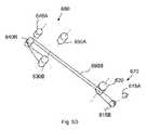
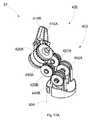
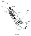
図1A〜図1Bは、近位端部(図示せず)および遠位端部31を有するツール30の一実施形態を示し、以降で説明するように、本ツールの手首部および本ツール30のケーブルルーティングの構成は、本ツールの手首部のサイズの低減を有利に可能にする。いくつかの実施形態において、この手首部のサイズの低減は、より単純なケーブルのルーティングによって可能になり、このルーティングは、本ツールの手首部アセンブリの複雑さの低減を可能にし、手首部の短縮された曲率半径を可能にする。いくつかの実施形態において、ツール30の手首部のサイズの低減には、手首部の直径の低減を含めることができる。 1A-1B show an embodiment of a
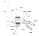
図1Aに示されるように、ツール30の遠位端部31は、ツール30のシャフト30Aに連結されたヨーク360を有することができる。ヨーク360は、(図2に示されるように)軸380に沿って延びる延長軸棒332を介して第2ヨーク330に動き可能に連結されている。一実施形態において、延長軸棒332は、第2ヨーク330に対して着脱可能にでき、または一体化して形成することもできる。他の実施形態において、延長軸棒332は、軸棒332の部分がヨーク360のアームに取り付けられて、ヨーク330が軸棒332の前記部分の間にはめ込めるように、ヨーク360に対して着脱可能にまたは一体化して形成することが可能である。一実施形態において、ツール30は、手術用ツールとすることができる。別の実施形態において、ツール30は、非手術用ツールとすることができる。 As shown in FIG. 1A, the
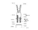
図1Bに示されるように、第2ヨーク330の延長軸棒332は、プーリ340A、340B、350A、350Bが延長軸棒332の軸380に沿って配置されるように、プーリ340A、340B、350A、350Bに連結される。プーリ340A、340B、350A、350Bは、プーリ340B、350Bの第1セット、およびプーリ340A、350Aの第2セットの中に配置される。プーリ340B、350Bの第1セットは、ヨーク330の一方側にあり、プーリ340A、350Aの第2セットは、ヨーク330の他方側にある。プーリ340A、340Bは、外側のプーリであり、350A、350Bは、内側のプーリである。 As shown in FIG. 1B, the
この用語「内側」および「外側」は、これらの図に示されたプーリの方位を示す。本明細書で用いる、プーリの「セット」は、任意の数のプーリを含み得る。或るプーリのセットは、1つのプーリを含んでよい。或るプーリのセットは、複数のプーリ(例えば、2つ、3つ、4つ、5つ、6つのプーリなど)を含んでよい。 The terms "inside" and "outside" refer to the orientation of the pulleys shown in these figures. As used herein, a "set" of pulleys may include any number of pulleys. A set of pulleys may include one pulley. A set of pulleys may include a plurality of pulleys (eg, two, three, four, five, six pulleys, etc.).
引き続き図1A〜図1Bを参照すると、第2ヨーク330は、プーリ320A、320Bの第3セットに連結される。プーリ320A、320Bの第3セットは、軸380から(例えば、遠位に)或る距離だけ離される。プーリ320A、320Bの第3セットは、第2ヨーク330のアーム330A、330Bに連結されて、アーム330A,330Bを貫いて定義される軸370に沿って配置されている。一実施形態において、第2ヨーク330には、軸370に沿って延びる延長軸棒を含めることができる。一実施形態において、延長軸棒は、第2ヨーク330に着脱可能に連結することが可能である。別の実施形態において、延長軸棒は、軸棒の部分が第2ヨーク330のアームに取り付けられ、プーリ320A、320Bが軸棒の前記部分の間にはめ込めるように、第2ヨーク330に一体化して形成することが可能である。一実施形態において、軸370は、軸380に対して角度を付けることができる。別の実施形態において、軸370は、軸380と直交させることが可能である。プーリ340B、350Bの第1セットは、プーリ320A、320Bの第3セットに対して直交させることができる。また、プーリ340A、350Aの第2セットも、プーリ320A、320Bの第3セットに対して直交させることが可能である。 With reference to FIGS. 1A to 1B, the
補捉具310の顎310A、310Bのペアは、顎310A、310Bが軸370の周りを回転可能なように、プーリ320A、320Bの第3セットを介して第2ヨーク330に連結することができる。一実施形態において、顎310Aは、プーリ320Aに連結される。別の実施形態では、顎310Aは、プーリ320Aに一体化して形成することが可能である。同様に、一実施形態において、顎310Bは、プーリ320Bに連結される。別の実施形態では、顎310Bは、プーリ320Bに一体化して形成することが可能である。顎310Aおよびプーリ320Aは、軸370の周りを回転することができる。同様に、顎310Bおよびプーリ320Bも、軸370の周りを回転することができる。この図示の実施形態において、捕捉具310は、ツール30のエンドエフェクタである。但し、他の実施形態では、エンドエフェクタは、外科手術(例えば、経皮外科手術)において用いられる諸メカニズムなど、他の適切なメカニズムとすることも可能である。 The pair of
ツール30は、顎310A、310Bの一方または両方が軸370の周りを様々な仕方で動くように、作動させることができる。例えば、顎310A、310Bは、相互に対して開いたり閉じたりすることが可能である。また、顎310A、310Bは、捕捉具310にヨー運動を与えるために、ペアとして一緒に回転するように作動させることもできる。さらに、ツール30は、軸380の周りに顎310A、310Bの様々な種類の運動を生じさせるように作動させることができる。例えば、第2ヨーク330、プーリ320A、320B、および顎310A、310Bは、捕捉具310にピッチ運動を与えるために軸380の周りを回転することが可能である。 The
図3A〜図3Bは、ツール30のケーブルの定位の実施形態を示す。有利には、以降に説明するように、ケーブルのこのルーティングによって、捕捉具310の運動を、4つの独立したケーブル端または2つのケーブルループの作動を介して制御することが可能になり、これは、捕捉具310を制御するために使われるケーブルの数を、市販のツール(これらは、通常、6つのケーブル端を有する3つのケーブルループを使用する)に比べて減らすことを可能にし、これにより、前述のように、ツール30の手首部のサイズおよび複雑さを有利に低減できる。本開示の実施形態で説明されるツールには、有益な特徴(例えば、4つの独立したケーブル端または2つのケーブルループだけの作動を介してエンドエフェクタの動作を制御する能力)が存在する。 3A-3B show embodiments of cable localization for the
図3A〜図3Bを参照すると、プーリ320A、320Bの第3セットは、各々ポケットまたは凹部を含むことができる。一実施形態において、このポケットは、ビード315A、315Bを少なくとも部分的に保持するサイズである。図3A〜図3Bには、ビード315Bが示されていないが、これらの図に示されたビード315Aと同様にすればよい。ビード315Aは、第1ケーブル390Aに固定することができ、ビード315Bは、第2ケーブル390Bに固定することが可能で、ケーブル390A、390Bの各々は、2つの独立したケーブル端を有する。ビード315A、315Bは、ケーブル390A、390Bがプーリ320A、320Bに対してスリップ(滑り)またはスライド(空進)するのを抑止(例えば防止)するようにケーブル390A、390Bに固定される。ケーブル390A、390Bは、ビード315A、315Bに固定的に連結される。一実施形態において、ビード315A、315Bは、ケーブル390A、390Bに一体化して形成することができる。別の実施形態では、ビード315A、315Bは、ケーブル390A、390B上に圧着することができる。 With reference to FIGS. 3A-3B, the third set of
図3Aは、第1ケーブル390Aのケーブルルーティングを示し、このルーティングは、図3中に点線で示される。第1ケーブル390Aは、ツール30の近位端部に始まりツールシャフト30Aを通って延びる。第1ケーブル390Aは、ヨーク360中の穴または開口30C(図1A参照)を通って延びる。第1ケーブル390Aは、プーリ340B、350Bの第1セット中の1つのプーリに少なくとも部分的に巻き付いている。第1ケーブル390Aは、プーリ320A、320Bの第3セット中の1つのプーリに少なくとも部分的に巻き付いている。第1ケーブル390Aは、プーリ340A、350Bの第2セット中の1つのプーリに少なくとも部分的に巻き付いている。いくつかの実施形態において、第1ケーブル390Aは、図3Aに示されるように、少なくとも部分的に、プーリ340B、プーリ320A、およびプーリ340Aに巻き付いている。その後、第1ケーブル390Aは、ヨーク360中の別の穴または開口30B(図1A参照)を通過し、ツールシャフト30Aを介してツール30の近位端部に帰る。 FIG. 3A shows the cable routing of the
いくつかの実施形態において、第1ケーブル390Aは、2つのケーブル390A’および390A”(図示せず)によって代替が可能であり、これらは、プーリ320Aに連結することができる(例えば、ケーブル390Aは、2つの別個のケーブル部分390A’、390A”で置き換えられる)。ケーブル390A’は、プーリ340B、350Bの第1セット中の1つのプーリに少なくとも部分的に巻き付き、ケーブル390A”は、プーリ340A、350Aの第2セット中の1つのプーリに少なくとも部分的に巻き付く。この実施形態において、ケーブル390A’、390A”は、プーリ320A、320Bの第3セット中の1つのプーリの一方側だけに進む。一実施形態において、ケーブル390A’、390A”の各々は、プーリ320Aの一方側だけに進む。いくつかの実施形態において、ケーブル390A’、390A”は、プーリ320Aに(例えば、ビード315Aを使って)固定的に連結される。例えば、ビード315Aは、ケーブル390A’、390A”の各々の端部上に圧着することができ、前述したように、ビード315Aをプーリ320Aのポケット中に保持し、これによりケーブル390A’、390A”をプーリ320Aに固定的に連結することができる。プーリ320Aに固定された2つの独立したケーブル390A’、390A”を有すること、またはプーリ320Aに固定された1つのケーブル390Aを有すること、の効果は、同じである。 In some embodiments, the
図3Bは、点線で第2ケーブル390Bを示す。第2ケーブル390Bは、ツール30の近位端部に始まりツールシャフト30Aを通って延びる。第2ケーブル390Bは、ヨーク360中の穴または開口30C(図1A参照)を通って延びる。第2ケーブル390Bは、プーリ340B、350Bの第1セット中の1つのプーリに少なくとも部分的に巻き付いている。第2ケーブル390Bは、プーリ320A、320Bの第3セット中の1つのプーリに少なくとも部分的に巻き付いている。第2ケーブル390Bは、プーリ340A、350Aの第2セット中の1つのプーリに少なくとも部分的に巻き付いている。いくつかの実施形態において、第2ケーブル390Bは、図3Bに示されるように、少なくとも部分的に、プーリ350B、プーリ320B、およびプーリ350Aに巻き付いている。その後、第2ケーブル390Bは、ヨーク360中の穴または開口30B(図1A参照)を通過し、ツールシャフト30Aを介してツール30の近位端部に帰る。 FIG. 3B shows the
いくつかの実施形態において、第2ケーブル390Bは、2つのケーブル390B’および390B”(図示せず)によって代替が可能であり、これらはケーブル390A’、390A”について前述したのと同様な方法で、プーリ320Bに連結することができる。上記から、いくつかの実施形態において、4つの独立したケーブル390A’、390A”、390B’、および390B”を用いることが可能である。例えば、一実施形態において、ケーブル390B’は、プーリ340B、350Bの第1セット中の1つのプーリに巻き付き、ケーブル390B”は、プーリ340A、350Aの第2セット中の1つのプーリに巻き付く。この実施形態において、ケーブル390B’、390B”は、プーリ320A、320Bの第3セット中の1つのプーリの一方側だけに進む。一実施形態において、ケーブル390A’、390A”は、プーリ320Bの一方側だけに進む。いくつかの実施形態において、ケーブル390B’、390B”は、プーリ320Bに(例えば、ビード315Bを使って、図示せず)固定的に連結される。例えば、ビード315Bは、ケーブル390B’、390B”の各々の端部上に圧着することができ、前述したように、ビード315Bをプーリ320Bのポケット中に保持し、これによりケーブル390B’、390B”をプーリ320Bに固定的に連結することができる。プーリ320Bに固定された2つの独立したケーブル390B’、390B”を有すること、またはプーリ320Bに固定された1つのケーブル390Bを有すること、の効果は、同じである。 In some embodiments, the
ツール30は、顎310A、310Bを、プーリ340A、340B、350A、350B、320A、320Bの1つ以上に運動を伝達し、これによりヨーク330、および/または顎310A、310Bの運動を与えることによって、(例えば、両顎を軸370周りに別々に回転させて)捕捉させる、(例えば、両顎を軸370周りに一緒に回転させて)ヨーイングさせる、および(例えば、両顎を軸380周りに回転させて)ピッチさせるなど、様々な仕方で動かすように作動させることができる。一実施形態において、ツール30が、捕捉具310の動作をもたらす2つのケーブル390A、390Bを有する場合、各ケーブル390A、390Bは、別々に制御可能な、またはプーリ320A、320Bの第3セットおよび顎310A、310Bに運動を与えるために張力をかけることが可能な2つの独立したケーブル端を有する。例えば、プーリ320Aと顎310Aとの運動は、ケーブル390Aの2つのケーブル端を使って制御が可能である。同様に、プーリ320Bと顎310Bとの運動は、ケーブル390Bの2つのケーブル端を使って制御することができる。図1A〜図3Bのシステムは、4つのケーブル端を有する。この4つのケーブル端は、プーリ340A、340B、350A、350B、320A、320Bの1つ以上に運動を与えるために制御することができる。この4つのケーブル端(各ケーブル390A、390Bに対するペア)は、以降にさらに説明するように、ツール30の近位端部32(図示せず)近くのモータに連結することが可能である。他の実施形態において、4つのケーブル端(各ケーブル390A、390Bに対するペア)は、ツールシャフト30A沿いの任意の距離に配置されたモータに連結することも可能である。 The
別の実施形態において、ツール30が、捕捉具310に動作をもたらす4つのケーブル390A’、390A”、390B’、390B”を有する場合、各々のケーブル390A’、390A”、390B’、390B”は、1つの独立したケーブル端を有し、これは、ヨーク330および/またはプーリ320A、320Bの第3セットの1つまたは両方に運動を与えるために、別々に制御または張力をかけることができる。独立したケーブル端は、自由ケーブル端(例えば、ビード315A、315Bに連結されていない端部)と見なし得る。プーリ320Aの運動は、ケーブル390A’、390A”の独立したケーブル端によって制御することができる。プーリ320Bの運動は、ケーブル390B’、390B”の独立したケーブル端によって制御することができる。図1A〜図3Bのシステムは、4つの独立したケーブル端を有する。この4つのケーブル端は、プーリ340A、340B、350A、350B、320A、320Bの1つ以上に運動を与えて、これによりヨーク330および/または顎310A、310Bの1つまたは両方に運動を与えるために制御することができる。4つのケーブル端(各ケーブル390A’、390A”、390B’、390B”の端部)は、ツール30の近位端部の近く(図示せず)またはツールシャフト30Aの任意の距離に配置されることができる。 In another embodiment, if the
いくつかの実施形態において、軸380周りのヨーク330および顎310A、310Bのピッチ運動は、1つのケーブル(例えば390A)の両端に張力をかけて、他方のケーブル(例えば390B)の両端を緩めることによって実現される。例えば、図3A〜図3Bを参照すると、顎310A、310Bを紙面平面の外側にピッチするためには、ケーブル390Aの両端に張力がかけられて、ケーブル390Bの両端は緩められる。顎を紙面平面の中にピッチするためには、ケーブル390Aの両端は緩められて、ケーブル390Bの両端に張力がかけられる。 In some embodiments, the pitch movement of the
いくつかの実施形態において、捕捉具310の顎310A、310Bの軸370周りのヨー運動は、プーリ320A、320Bを同じ方向に動かして実現される。例えば、図3Aを参照すると、顎310A、310Bを上側にヨーイングするには、両方のプーリ320A、320Bが反時計回り方向に動く必要がある。プーリ340B、350Bの第1セット中の1つのプーリに連結されたケーブル390Aの端部に張力がかけられて、プーリ340B、350Bの第1セット中の1つのプーリに連結されたケーブル390Bの端部に張力がかけられる。図3Aにおいて、340Bに連結されたケーブル390Aの端部、および350Bに連結されたケーブル390Bの端部に張力がかけられる。ケーブル390A、390Bの他方の端部は、緩められる。これにより、顎310A、310Bは、軸370の周りを上方に回転する。顎310A、310Bを下方にヨーイングさせるためには、プーリ320A、320Bの両方が時計回り方向に動かなければならない。プーリ340A、350Aの第2セットの1つのプーリに連結されたケーブル390Aの端部、およびプーリ340A、350Aの第2セットの1つのプーリに連結されたケーブル390Bの端部には、張力がかけられる。図3A〜図3Bにおいて、340Aに連結されたケーブル390Aの端部、および350Aに連結されたケーブル390Bの端部に張力がかけられる。390A、390Bの他方の端部は、緩められる。ケーブル390A、390Bの緊張および弛緩のかかる組み合わせが、顎310A、310Bを軸370周りに下方へ回転させることになる。 In some embodiments, the yaw motion around the
顎310A、310Bは、例えば、捕捉アクション、解放アクション、またははさみ切り運動をもたらすために、相互に対して動かすことが可能である。顎310A、310Bを相互に向けて動かすために、プーリ320Aは、反時計周り方向に動くことができて、プーリ320Bは、時計周り方向に動くことができる。かかる運動を実現するために、プーリ340B、350Bの第1セットの1つのプーリに連結されたケーブル390Aの端部、およびプーリ340A、350Aの第2セットの1つのプーリに連結されたケーブル390Bの端部に張力がかけられる。図3A〜3Bにおいて、340Bに連結されたケーブル390Aの端部、および350Aに連結されたケーブル390Bの端部に張力がかけられる。390A、390Bの他方の端部は、緩められる。ケーブル390A、390Bの緊張および弛緩のかかる組み合わせが、顎310A、310Bを相互に向けて軸370周りに回転させることになる。 The
顎310A、310Bを離すために、プーリ320Aは、時計回り方向に動き、プーリ320Bは、反時計回り方向に動くことができる。プーリ340A、350Aの第2セット中の1つのプーリに連結されたケーブル390Aの端部、およびプーリ340B、350Bの第1セット中の1つのプーリに連結されたケーブル390Bの端部に張力がかけられる。図3A〜3Bにおいて、340Aに連結されたケーブル390Aの端部、および350Bに連結されたケーブル390Bの端部に張力がかけられる。390A、390Bの他方の端部は、緩められる。ケーブル390A、390Bの緊張および弛緩のかかる組み合わせが、顎310A、310Bを相互から離れるように軸370周りに回転させることになる。 In order to separate the
顎310A、310Bは、各ケーブルの端部に相異なる張力の量をかけることによって、相互に向かいまたは離れるように動かすことができる。変化する張力量をかけることによって、顎310A、310Bは、いろいろなヨーイングをして、捕捉または開放アクションを効果的に模擬することになる。全3つの動作モード(ピッチ、ヨー、および捕捉アクション)は、張力をかけたり緩めたりするケーブル端を変えることによって、および/または各ケーブル端に適用する張力および緩和の量を変えることによって得ることができる。図1A〜図3Bには、特定のルーティング構成が描かれているが、他のルーティング構成も可能である。例えば、ケーブル390Aは、前述の外側プーリ340Bに巻き付ける代わりに、内側のプーリ350Bに巻き付けてもよい。 The
いくつかの実施形態において、ツールの手首部および/またはエンドエフェクタの運動は、1本以上の撚り紐を使ってもたらすことができる。撚り紐のペアは、撚られた紐のペアが短縮され得て、これにより撚られた紐のペアに沿って張力を生成するという、相互周りに2本の構成紐を撚ることの原理によって働く。同様に、撚り紐ペアの元紐がほどけるにつれて、その撚り紐ペアの長さは、各元紐の自然の長さに近づくことがある。図4A〜図4Dは、撚り紐およびケーブルを使って、ツール30などのツールを制御する駆動メカニズムおよび方法の実施形態を示す。図4Aは、ツールのケーブルを制御するための駆動メカニズム500Aを概略的に示す。このシステムは、2つのケーブル521,522を含む。各ケーブル521,522は、プーリ510A、510Bに関連付けられる。プーリ510A、510Bは、駆動される対象である。1つのプーリ510Bが示されているが、ケーブル521は、複数のプーリに関連付けることができる。同様に、1つのプーリ510Aが示されているが、ケーブル522は、複数のプーリに関連付けることができる。各ケーブル521、522は、2つのケーブル端を有する。各ケーブル端は、移行ブロック530A、530B、530C、530Dに連結されている。各移行ブロック530A、530B、530C、530Dは、撚り紐ペア520A、520B、520C、520Dに連結されている。各撚り紐ペア520A、520B、520C、520Dは、モータ515A、515B、515C、515Dに連結されている。 In some embodiments, the movement of the wrist and / or end effector of the tool can be brought about using one or more twisted cords. Twist pairs are based on the principle of twisting two constituent strings around each other, where the twisted string pair can be shortened, thereby creating tension along the twisted string pair. work. Similarly, as the original cord of the twisted cord pair is unwound, the length of the twisted cord pair may approach the natural length of each original cord. 4A-4D show embodiments of drive mechanisms and methods for controlling tools such as the
引き続き図4Aを参照すると、各撚り紐ペア520A、520B、520C、520Dは、軸型モータ515A、515B、515C、515Dによって駆動される。例えば、撚り紐ペア520Aは、軸型モータ515Aによって駆動され、撚り紐ペア520Bは、軸型モータ515Bによって駆動される。 Continuing with reference to FIG. 4A, each
移行ブロック530A、530B、530C、530Dは、撚り紐ペア520A、520B、520C、520Dとケーブル521,522との間での移行を提供する。図4Aに示されるように、ケーブル521は、移行ブロック530Bと530Cとの間に延びる。ケーブル522は、移行ブロック530Aと530Dとの間に延びる。撚り紐ペア520A、520B、520C、520Dは、該撚り紐ペアがその上に屈曲する必要のある表面(例えば、プーリ510A、510Bの曲面)に接触するときに、予測不能な挙動を示すことがあるので、このため、ケーブル521,522だけがプーリ510A、510Bの曲面に接触するように、移行ブロック530A、530B、530C、530Dは、撚り紐ペア520A、520B、520C、520Dとケーブル521,522との間での移行を提供する。 The transition blocks 530A, 530B, 530C, 530D provide a transition between the twisted string pairs 520A, 520B, 520C, 520D and the cables 521,522. As shown in FIG. 4A,
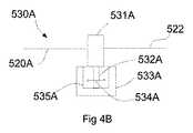
図4Bは、移行ブロック530Aを示す。一実施形態において、全4つの移行ブロック530A、530B、530C、および530Dは、移行ブロック530Aと同様の特徴を有する。撚り紐ペア520Aは、終端ブロック531Aに連結されている。また、ケーブル522も、終端ブロック531Aに連結されている。終端ブロック531Aは、ペグ532Aに固定的に連結されている。一実施形態において、終端ブロック531Aは、ペグ532Aと一体化して形成することが可能である。 FIG. 4B shows the
ペグ532Aは、撚り紐ペア520Aが長さを短縮または延長できるように、矢印線534A沿いに、ベースブロック533A中のスロット535A内でスライドすることができる。この図示の実施形態において、ペグ532Aおよびスロット535Aの両方は、ベースブロック533Aの内部構造体であって、点線の形状で示されている。ペグ532Aおよびスロット535Aは、終端ブロック531Aが、撚り紐ペア520Aの影響によって回転またはスピンするのを有利に防止する。撚り紐ペア520Aの長さが減少したとき、終端ブロック531Aに連結されたペグ532Aは、ベースブロック533A中のスロット535A内でスライドし、これにより、終端ブロック531Aは、ケーブル522を引き寄せる。ケーブル522は、この張力をプーリ510Aに伝えて、プーリ510Aを回転させる。 The
引き続き図4Aを参照すると、撚り紐ペア520Aは、撚り紐ペア520Cに対して移動される。モータ515Aは、モータ515Aに固定された撚り紐ペア520Aを巻き取って、これにより撚り紐ペア520Aの長さを短縮することができる。モータ515Cは、モータ515Cに固定された撚り紐ペア520Cの巻きを解き、これにより撚り紐ペア520Cの長さを延長することができる。これらの2つのアクションは、ケーブル522をモータ515Aの方へ引き寄せて、プーリ510Aを反時計回り方向に回転させる。プーリ510Aを時計回りの方向に動かすには、モータ515Aが撚り紐ペア520Aの巻きを解き、モータ515Cが撚り紐ペア520Cを巻き取ることになろう。モータ515B、515Dも、同様の仕方でケーブル521とプーリ510Bとを動かすことが可能である。ケーブル521,522は、ビード315A、315Bと同じようなビードに連結することができ、そのビードをプーリ510A、510Bに連結する(例えば、前述した方法でプーリ510A、510Bのポケット中に保持する)ことができる。さらに、他の実施形態において、ケーブル521、522の各々を、各2つの独立したケーブルで代替して、移行ブロック530A、530B、530C、530Dと、プーリ510A、510B上のビードとの間に4つのケーブルを延ばすことが可能である。 Continuing with reference to FIG. 4A, the
プーリ510A、510Bを駆動する別のモードにおいて、両方の撚り紐ペアは、等しく巻き取ることができる。例えば、モータ515A、515Cの両方が撚り紐ペア520Aおよび520Cを巻き取り、この間、モータ515B、515Dは、作動されない。この場合、プーリ510Aは、回転はされないがモータ515A、515Cの方向への引っ張り力を受けて、矢印523沿いにこの面(page)の中の方へのヨー運動をもたらすことになる。上記に換えて、モータ515B、515Dが撚り紐ペア520B、530Dを巻き取るように作動されて、一方、モータ512A、515Cが作動されない場合、プーリ510Bは、回転はされないがモータ515B、515Dの方向への引っ張り力を受けて、矢印523と反対の方向にこの面の外の方へのヨー運動をもたらすことになる。前述に加えて、ヨー運動の量は、撚り紐ペアが巻かれる量によって制御することが可能である。 In another mode driving the
図4Cは、ツール30などのツールを制御するための別の駆動メカニズム500Bを概略的に示す。このシステムは、プーリ580に関連付けられたケーブル570を含む。この図示の実施形態において、ケーブル570は、以降でさらに説明するように、1本以上の撚り紐ペアを定義する。1つだけのプーリ580が示されているが、前述のように、該ケーブルは、複数のプーリに関連付けることができる。さらに、本システムは、第2プーリ(図示せず)に関連付けられた第2ケーブル(図示せず)を含むことが可能である。この図示の実施形態において、プーリ580は、駆動される対象である。前述の諸実施形態で説明したように、ケーブル570は、2つの移行ブロック565A、565Bに連結される。 FIG. 4C schematically shows another
各移行ブロック565A、565Bは、撚り紐ペア560A、560Bに連結される。各撚り紐ペア560A、560Bは、ループ555A、555Bを形成する。各ループ555A、555Bは、モータ550A、550Bに連結される。撚り紐ペア560Aは、二重重ねのケーブル570によって定義される。すなわち、ケーブル570は、移行ブロック565Aに連結して(例えば、移行ブロック530Aと同様に、ペグが移行ブロック565Aのベースブロック上を回転せずにスライドでき、移行ブロック565Aのペグに連結する)、移行ブロック565Aを通過して延び、撚り紐ペア560Aおよびループ555Aを定義して、移行ブロック565Aに戻って連結する。同様に、撚り紐ペア560Bも、二重重ねのケーブル570によって定義される。すなわち、ケーブル570は、移行ブロック565Bに連結して、移行ブロック565Bを通過して延び、撚り紐ペア560Bおよびループ555Bを定義して、移行ブロック565Bに戻って連結する。 Each
モータ550Aおよび550Bは、ループ555A、555Bを巻き取りまたは巻き解き、その結果として撚り紐ペア560A、560Bを巻き取りまたは巻き解くことができる。したがって、ケーブル570は、移行ブロック565A、565Bの終端ブロックの両方の側から延びている。ケーブル570は、ビード575に取り付けることができ、これは、図3A中のビード315Aへのケーブルの取り付けと同様に行うことができる。駆動メカニズム500Bは、図4A中の駆動メカニズム500Aに比べて少ない部品(例えば1つのケーブル)を有利に有する。
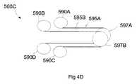
図4Dは、ツール30などのツールのケーブルを制御するための別の駆動メカニズム500Cを概略的に示す。このシステムは、2つのケーブル595A,595Bを含む。各ケーブル595A,595Bは、プーリ597A、597Bに関連付けられる。プーリ597A、597Bは、駆動される対象である。各ケーブル595A,595Bは、2つのケーブル端を有する。各ケーブル端は、モータ590A、590B、590C、590Dによって駆動される。これらのモータは、扁平な高トルクモータ(電気モータ)とすることができる。他の実施形態において、他の種類のモータを用いることは、可能である。ケーブル595A、595Bを巻き取り、巻き解くスプールは、図示されていない。 FIG. 4D schematically shows another
図5A〜図6Dは、前述した駆動メカニズムを含めて、本明細書で説明するツールに組み込みが可能なメカニズムの実施形態を示す。図5Aは、ツールの別の実施形態を示す。このツール600は、遠位端部670および近位端部680を含む。遠位端部670は、図1A〜図3B中に示されたツール30の遠位端部31と実質的に同様とすればよい。明瞭化のため、図5Aでは、遠位端部670を駆動するケーブルは示されていない。前述した諸実施形態と同様に、ツール600の手首部および/またはエンドエフェクタの運動をもたらすために、4つのケーブル端を有する2つのケーブルループが制御される。この図示の実施形態において、ツール600は、4つのモータ660A、660B、660C、660Dを含むことができる。但し、これらのケーブルを駆動して4つのケーブル端を制御するため、必要なモータは、3つだけである。一実施形態において、第4のモータは、ツール600の遠位端部670にツール軸周りの転がりまたは回転を与えることができる。いくつかの実施形態において、ツール600は、3つだけのモータを含む。 5A-6D show embodiments of mechanisms that can be incorporated into the tools described herein, including the drive mechanisms described above. FIG. 5A shows another embodiment of the tool. The
ツール600は、4つのプーリ630A、630B、640A、640Bを含むことができる。プーリ630A、630Bは、プーリ640A、640Bに対して遠位に配置されることができる。プーリ630A、630Bは、前部プーリと見なすことができ、プーリ640A、640Bは、後部プーリと見なすことができる。前部プーリ630A、630Bの各々は、それぞれ、モータ660A、660Bにより駆動される。後部プーリ640A、640Bは、ロッカーメカニズム650に連結されている。 The
図5Bは、ロッカーメカニズム650を示す。図5Bでは、ロッカーメカニズム650をより明瞭に表すため、モータ660A、660Bは図示されていない。ロッカーメカニズム650は、軸668周りを行き来して(時計方向および反時計方向に)揺動することができる。図示のように、プーリ640A、640Bの軸は、ロッカーメカニズム650の端部に連結されている。一実施形態において、プーリ640A、640Bの軸で定義される面(例えば、ツールの長手軸と直交する面)は、軸668が前記面上に横たわらないように(例えば、ロッカーメカニズム650とプーリ640A、640Bとの軸によって定義される面が三角形を区画するように)、軸668から軸方向にオフセットすることができる。別の実施形態では、プーリ640A、640Bの軸および軸668は、ツール600の長手軸と直交する同一の面上に置くことも可能である。 FIG. 5B shows the
ロッカーメカニズム650が反時計方向に回転すると、プーリ640Bは、ツール600の遠位端部670の方へ移動し、プーリ640Aは、ツール600の近位端部680の方へ移動する。ロッカーメカニズム650が時計方向に回転すると、プーリ640Bは、ツール600の近位端部680の方へ移動し、プーリ640Aは、ツール600の遠位端部670の方へ移動する。ロッカーメカニズム650の位置は、モータ(例えばモータ660D)によって決められる。モータ660Dは、リードスクリューに連結してもよい。リードスクリューは、スクリューナットと結び付けてもよく、該ナットは、リードスクリューの長手に沿って平行移動する。このリードスクリューナットは、プッシュロッドに連結してもよい。このプッシュロッドは、ロッカーメカニズム650に連結してもよい。モータ660Dが回ると、プッシュロッドがリードスクリュー上を平行移動し、ロッカーメカニズム150の位置を変化させる。前述のように、ロッカーメカニズム150は、プーリ640A、640Bの位置を調整し、これにより、これらプーリは、プーリ640A、640Bに連結されたケーブルに加えられる張力を調整する。 As the
図5Cは、ツール600の第1ケーブル690Aのルーティングを示す。遠位セクション670中のケーブルのルーティングは、図3A〜図3B中に示されたケーブルルーティングと実質的に同様とすればよい。プーリ615A、615Bは、プーリ320A、320Bと実質的に同様とすればよい。図5A中に示されるように、プーリ615A、615Bは、顎610A、610Bに連結することが可能である。プーリ620は、プーリ340A、340B、350A、350Bと類似である。図5Cに示されるように、ケーブル690Aの両側は、プーリ620に対して近位側から同じ方向でプーリ620の周りに巻き付いており、ケーブル690Aの2つの側は、ツールシャフト605(図5A参照)を通って進み、プーリ640Aの周りに少なくとも部分的に巻き付いている。ケーブル690Aの両自由端は、プーリ640Aを抜け出た後、スプール630Aの各反対側に固定されている。ケーブル690Aの両自由端は、各反対方向でスプール630Aに少なくとも部分的に巻き付いている。スプール630Aは、モータ(例えばモータ660A)によって作動される。スプール630Aが回転する速度は、モータ660Aに連結されたギアボックスを介して制御することができる。モータ660Aが回ると、スプール630Aが回り、ケーブル690Aの一方の端に張力を加え、同一のケーブル690Aの他方の端の張力を緩める。ケーブル690Aは、図3A中のケーブル390Aがビード315Aに連結している仕方と同じ仕方で、プーリ615Aのポケットまたは凹部中に保持されるビードに連結することができる。 FIG. 5C shows the routing of the
スプール630Aが回転すると、第1ケーブル端は、巻き解かれて、第2ケーブル端は、スプール630A周りに巻き取られる。この型の運動の効果は、プーリ620は回転しないがプーリ615Aは回転することになり、これがプーリ615Aに取り付けられた顎610Aを動かすことになる、ということである。例えば、顎610Aを上方にヨー運動させるには、プーリ615Aは、反時計回り方向に動く必要がある。顎610を上方にヨーイングさせるには、上側ケーブル端をスプール630Aの周りに巻き付けることによって、該ケーブル端に張力を加える必要があろう。顎を下方にヨーイングさせるには、下側ケーブル端に張力を加えることが必要であろう。ロッカーメカニズム650は、中立位置にすることができる(例えば、プーリ640A、640Bがツール600の長手軸に直交する面に沿って整列される)。 When the
ツール600は、顎610A、610Bを、(例えば、プーリ615A、615Bを介して別々に回転させて)捕捉させる、(例えば、プーリ615A、615Bを介して、両顎を一緒に回転させて)ヨーイングさせる、および(例えば、プーリ620の周りに両顎を回転させて)ピッチさせるなど、様々な仕方で動くよう作動させることができる。図5Dは、ツール600中の第2ケーブルのルーティングを示す。このルーティングは、図5Cで説明したものと類似である。ケーブル690Bは、プーリ620周り、プーリ640Bの周りに巻き付き、スプール630で終端している。スプール630Bは、モータ(例えばモータ660B)によって駆動される。スプール630Bが回転すると、ケーブル690Bの一方の側には張力がかかり、ケーブル690Bの他方の側の張力は緩められる。この回転の効果は、プーリ615Bに取り付けられた顎610Bを動かすことである。
顎610A、610Bの両方を同時に上方に動かすために、スプール630A、630Bは、プーリ615A、615Bを反時計回りに動かすようにモータで駆動される。この運動は、顎610A、610Bをヨーイングさせることになる。両顎610A、610Bを同時に下方に動かすために、スプール630A、630Bは、プーリ615A、615Bを時計回りに動かすようにモータで駆動される。 In order to move both
ピッチをもたらすには、ロッカーメカニズム650を操作して、ツール600の長手軸に対してプーリ640A、640Bの位置を変化させる。図5Eは、ロッカーメカニズム650が時計方向に回転されて、プーリ640Aをツール600の遠位端部670の方へ移動させ、プーリ640Bをツール600の近位端部680の方へ移動させるのを示す。この実施形態において、ロッカーメカニズム650のこの位置は、ケーブル690Bの両側の張力を増大する。この張力は、プーリ620を時計方向に回転させ、それは、矢印線695で示すように、ツール600の手首部および顎610A、610Bを時計回り方向にピッチさせる。プーリ620を反対方向に回転させるために、ロッカーメカニズム650は、反時計回り方向に回転されて、プーリ640Aをツール600の近位端部680の方へ移動させ、プーリ640Bをツール600の遠位端部670の方へ移動させる。これは、ケーブル690Aの張力を増大し、それは、プーリ620を反時計回りに回転させ、次にそれは、ツール600の手首部および顎610A、610Bを反時計回り方向(矢印線695で示されたのと反対方向)にピッチさせる。本明細書で説明するリードスクリューおよびプッシュロッドの実装は、+/−90°までまたはそれより大きいピッチ(例えば、合計で180°以上)を可能にすることができる。ロッカーメカニズム650の使用は、一方のケーブルの張力の増大(例えば、1つのケーブルがプーリ615A、615Bに達するために進む必要のある距離を長くする)と、もう一方のケーブルの張力の低減または緩和(例えば、1つのケーブルがプーリ615A、615Bに達するために進む必要のある距離を短くする)とをもたらす。 To provide pitch, the
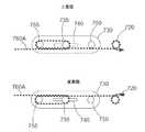
図6Aは、ツールの別の実施形態を示す。このツール700は、遠位端部770および近位端部780を含む。遠位端部770は、図1A〜図3B中に示されたツール30の遠位端部31と実質的に同様とすればよい。ツール700は、顎710A、710Bを、(例えば、プーリ715A、715Bを介して、両顎を別々に回転させて)捕捉させる、(例えば、プーリ715A、715Bを介して、両顎を一緒に回転させて)ヨーイングさせる、および(例えば、両顎をプーリ720の周りに回転させて)ピッチさせるなど、様々な仕方で動くよう作動させることができる。ツール700は、図5Bで説明したロッカーメカニズム650に換えて、顎のピッチ運動をもたらすシャトルメカニズム730を含む。明瞭化のため、図6Aではツール700に対するケーブルルーティングは示されていない。また、一実施形態において、ツール700は、ツール700の(プーリ640A、640Bと類似の)後部プーリを保持して、近位端部でケーブルのルーティングを(例えば、プーリ640A、640Bがプーリ630A、630Bに向けてケーブルルーティングを反転させた仕方と同様な仕方で)反転させるための、ロッカーメカニズム650も含むことができる。すなわち、一実施形態において、ツール700の近位端部は、ツール600の近位端部と同じ構造を有することが可能である。 FIG. 6A shows another embodiment of the tool. The
ここで図6Bを参照すると、第1ケーブル760Aに対するケーブルルーティングを備えるシャトルメカニズム730の上面図および底面図が示されている。この図示の実施形態において、シャトルメカニズム730の中央プーリ735の軸棒は、ツールシャフト705の胴体に固定的に連結される。シャトルメカニズム730は、ツールシャフト705の長手軸に沿って前後に直線的にスライドすることが可能である。 Here, with reference to FIG. 6B, a top view and a bottom view of the
図6Bの上面図を見ると、ケーブル760Aは、近位端部780からツールシャフトの胴体に入っている。ケーブル760Aは、中央プーリ735の周りに少なくとも部分的に巻き付いている。ケーブル760Aは、近位端部780の方へ戻って延び、シャトルプーリ755の周りに少なくとも部分的に巻き付いている。ケーブル760Aは、次いで遠位端部770の方へ延び、プーリ720の周りに少なくとも部分的に巻き付いている。プーリ720は、前述したプーリ620と実質的に類似にすることができ、ツール700の手首部として機能することが可能である。プーリ720は、ヨーク790に連結されて、図6Aに示されるように、該ヨークは、顎710A、710Bに連結されている。図6Bの底面図を見ると、ケーブル760Aは、プーリ720に巻き付いた後、遠位端部770側からツールシャフトの胴体に入っている。ケーブル760Aは、近位端部780の方へ戻って延び、シャトルプーリ755の周りに少なくとも部分的に巻き付いている。ケーブル760Aは、次いで遠位端部770の方へ延びて、中央プーリ735の周りに少なくとも部分的に巻き付き、その後、ケーブル760Aは、近位端部780の方へ延びる。 Looking at the top view of FIG. 6B, the
図6Cは、第2ケーブル760Bに対するケーブルルーティングを含むシャトル730の上面図および底面図を示す。図6Cの上面図を見ると、ケーブル760Bは、近位端部780からツールシャフトの胴体705に入っている。ケーブル760Bは、シャトルプーリ750の周りに少なくとも部分的に巻き付いている。ケーブル760Aは、近位端部780の方へ戻って延び、中央プーリ735の周りに少なくとも部分的に巻き付いている。ケーブル760Aは、遠位端部770の方へ延び、プーリ720の周りに少なくとも部分的に巻き付いている。プーリ720は、ヨーク790に連結されて、図6Aに示されるように、該ヨークは、顎710A、710Bに連結されている。図6Cの底面図を見ると、ケーブル760Bは、プーリ720に巻き付いた後、遠位端部770側からツールシャフトの胴体705に入っている。ケーブル760Bは、近位端部780の方へ戻って延びて、中央プーリ735の周りに少なくとも部分的に巻き付いている。ケーブル760Bは、次いで遠位端部770の方へ延びて、シャトルプーリ750の周りに少なくとも部分的に巻き付き、その後、ケーブル760Bは、近位端部780の方へ延びる。 FIG. 6C shows a top view and a bottom view of the
ツール700の手首部および顎710A、710Bにピッチをもたらすために、シャトルメカニズム730は、ツール700の長手軸沿いにシャトルメカニズム730の位置を変えるように調整される。図6Dは、ツール700の遠位端部770の方へシフトされるシャトルメカニズム730を示す。シャトルメカニズム730の位置は、モータ(例えば、図5Aに示されたモータ660D)に取り付けられたメカニズム(例えば、プッシュロッド、リードスクリュー、ケーブル伝動装置)によって調整される。図6Dは、シャトルメカニズム730を遠位端部770の方へ直線的に平行移動する効果を示す。図6Dの上の方の2つの図は、ケーブル760Bに対するケーブルルーティングを示し、下の方の2つの図は、ケーブル760Aに対するケーブルルーティングを示す。シャトルメカニズム730のこの位置は、ケーブル760Bの両側の張力を増大する。ケーブル760Bがプーリ720に達するために進まねばならない距離は、増加しており(例えば、シャトルプーリ750と中央プーリ735と間の距離は、増加しており)、一方、ケーブル760Aがプーリ720に達するために進まねばならない距離は、減少している(例えば、中央プーリ735とシャトルプーリ755と間の距離は、減少している)。その結果、ケーブル760Bによってプーリ720上に加えられる張力は、増加し、ケーブル760Aによってプーリ720に加えられる張力は、減少する。この張力は、プーリ720を矢印線765方向の反時計回り方向に回転させる。前述したケーブルルーティングには、他の実施形態ではここに記載されたものとは別のプーリのセットを用いることが可能であるが、そうであっても、シャトルメカニズム730の使用は、一方のケーブルの張力の増大(例えば、1つのケーブルがプーリ715A、715Bに達するために進まなければならない距離の伸長)と、もう一方のケーブルの張力の低減または緩和(例えば、1つのケーブルがプーリ715A、715Bに達するために進まなければならない距離の減少)とをもたらす。 To provide pitch to the wrist and
プーリ720(例えば手首部のプーリ)を反対方向に回転させるために、シャトルメカニズム730は、ツール700の近位端部780の方へ平行移動される。この張力は、プーリ720を時計回り方向に回転させる。シャトルの位置が近位端部780に向かうとともに、ケーブル760A上の張力は、増大し、手首部(例えばプーリ720)は、矢印線765のように反対方向にピッチすることになる。本明細書で説明するシャトルメカニズム730の実装は、+/−90°までまたはそれより大きいピッチ(例えば、合計で180°以上)を可能にすることができる。 To rotate the pulley 720 (eg, the wrist pulley) in opposite directions, the
前述のように、ロッカーメカニズム650およびシャトルメカニズム730は、第1ケーブルの張力を増大し、第2ケーブルの張力を緩める。このロッカーメカニズム650およびシャトルメカニズム730を用いて、プーリ620、720または任意のプーリの組み合わせ(例えば、図1Aに示されたプーリ群)の動作をもたらすことができる。 As mentioned above, the
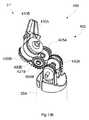
図7Aは、ツールの別の実施形態を示す。このツール1000は、10個のプーリ、1010A、1010B、1020A、1020B、1030A、1030B、1040A、1040B、1050A、1050Bを有する。プーリ1010A、1020Aは、第1セットに配置される。プーリ1010B、1020Bは、第2セットに配置される。プーリ1050A、1050Bは、第3セットに配置される。プーリの第3セットは、プーリの第1セットおよび/またはプーリの第2セットに対して角度を付けることができる。 FIG. 7A shows another embodiment of the tool. The
プーリ1030A、1040Aは、第4セットに配置される。プーリ1030B、1040Bは、第5セットに配置される。プーリの第3セットは、プーリの第4セットおよび/またはプーリの第5セットに対して角度を付けることができる。この図示の実施形態において、プーリ1010A、1020Aの第1セットは、プーリ1030A、1040Aの第4セットと直列にすることが可能である。プーリ1010B、1020Bの第2セットは、プーリ1030B、1040Bの第5セットと直列にすることが可能である。プーリ1010A、1020Aの第1セットは、プーリ1010B、1020Bの第2セットとともに或る回転軸に沿って配置されることができる。プーリ1030A、1040Aの第4セットは、プーリ1030B、1040Bの第5セットとともに或る回転軸に沿って配置されることができる。プーリ1010A、1010B、1020A、1020B、1030A、1030B、1040A、1040Bの他の配置も可能である。 The
図7Bを参照すると、プーリ1050A、1050Bの第3セットは、回転軸1060に沿って配置されることができる。プーリ1030A、1040Aの第4セットおよびプーリ1030B、1040Bの第5セットは、回転軸1070に沿って配置されることができる。プーリ1050A、1050Bの第3セットの回転軸1060は、プーリ1030A、1040Aの第4セットおよびプーリ1030B、1040Bの第5セットの回転軸1070に対して角度を付けて、プーリ1030Bおよび1040A上の溝は、それぞれ、プーリ1050Aおよび1050B上の溝と整列し、これにより、ケーブルは、プーリ1030Bおよび1040Aとプーリ1050A、1050Bとの間で真っすぐな経路をたどり、ケーブルの湾曲およびケーブルとプーリとの間の摩擦が低減されるようにすることが可能である。 With reference to FIG. 7B, a third set of
プーリ1010A、1020Aの第1セットおよびプーリ1010B、1020Bの第2セットは、図7Aに示されるように、回転軸1070’に沿って配置されることができる。プーリ1050A、1050Bの第3セットの回転軸1060は、プーリ1010A、1020Aの第1セットおよびプーリ1010B、1020Bの第2セットの回転軸1070’に対して角度を付けることができる。 The first set of pulleys 1010A, 1020A and the second set of pulleys 1010B, 1020B can be arranged along the axis of rotation 1070'as shown in FIG. 7A. The
第1ケーブルおよび第2ケーブルのルーティングが図7Aに示されている。プーリ1050A、1050Bは、ヨーク1055に連結される。ヨーク1055は、ヨーク1055の表面から延びる2つの取り付け具1055A、1055Bを有することができる。一実施形態において、ツール1000の顎は、取り付け具1055A、1055Bを介してプーリ1050A、1050Bに連結することが可能である。このケーブルルーティングは、図1A〜図3Bに関連して説明したルーティングと同様にすればよい。各ケーブルは、プーリ1030A、1040Aの第4セット中の1つのプーリおよびプーリ1030B、1040Bの第5セット中の1つのプーリの周りに少なくとも部分的に巻き付く。いくつかの実施形態において、プーリ1050A、1050Bの第3セットの角度は、プーリ1030A、1040Aの第4セットおよびプーリ1030B、1040Bの第5セットに行き来するケーブルが、プーリ1050A、1050Bの第3セットに真っすぐな経路をたどるように、配置される。ツール1000は、顎(図示しない)を、(例えば、プーリ1050A、1050Bを介して、両顎を別々に回転させて)捕捉させる、(例えば、プーリ1050A、1050Bを介して、両顎を一緒に回転させて)ヨーイングさせる、および(例えば、両顎を軸1030A、1040A、1030B、1040Bの周りに回転させて)ピッチさせるなど、様々な仕方で動かすように作動させることができる。 The routing of the first and second cables is shown in FIG. 7A. The
他の実施形態において、ツールは、剛性部分と柔軟性部分とを含むことができ、柔軟性部分を選択的に硬化しおよび/または所定位置にロックし、これにより該ツールの少なくとも一部に屈曲形状をもたらすことが可能である。いくつかの実施形態において、選択的に硬化可能な前記柔軟性部分は、ツールの手首部の近位側に配することができ、ツールの手首部は、本明細書の実施形態中で開示した任意の構成を有することができる。上記から、いくつかの実施形態において、ツールは、手首部と、ツールのエンドエフェクタをいろいろな幾何的配置に位置付けるよう作動することができる別のジョイントを提供する、手首部から近位の柔軟性部分と、を有し、これによりツールの遠位端部の運動の範囲を有益に拡大することが可能である。 In other embodiments, the tool can include a rigid portion and a flexible portion, which selectively cures and / or locks in place, thereby flexing into at least a portion of the tool. It is possible to bring shape. In some embodiments, the selectively curable flexible portion can be located proximal to the wrist of the tool, the wrist of the tool being disclosed in embodiments herein. It can have any configuration. From the above, in some embodiments, the tool provides wrist-to-proximal flexibility that provides a wrist and another joint that can act to position the tool's end effectors in various geometric arrangements. It has a portion, which can beneficially extend the range of motion of the distal end of the tool.
図8A〜図9Cは、本明細書に記載のツール中に組み込みが可能な柔軟性セクションの諸実施形態を示す。図8Aは、ツールの別の実施形態を示す。このツール1300は、ツールシャフト1302の一部に沿った屈曲部または肘部を含むことができる。ツール1300は、1つ以上の剛性セクション1310を含むことが可能である。ツール1300は、1つ以上の柔軟性セクション1305を含むことが可能である。柔軟性セクション1305は、シース1320を含み、シースは、平行線模様で図示されている。ツール1300は、エンドエフェクタ1340(例えば捕捉具)を含むことができる。ツール1300は、例えば、障害物を迂回して所望の位置または対象物に到達するため、非直線の形状を実現するように、屈曲するまたは別途に操作することが可能である。さらに、ツール1300は、柔軟性セクション1305を選択的に硬化および/または所定位置にロック(例えば、前記屈曲形状を維持するために)できるようにアレンジされることができる。 8A-9C show embodiments of flexibility sections that can be incorporated into the tools described herein. FIG. 8A shows another embodiment of the tool. The
いくつかの実施形態において、手術用途に使われる場合、ツール1300は、トロカールを通して挿入することが可能である。トロカールは、一般に直線形状を有するので、ツール1300は、トロカールを通して挿入するために長手軸に沿って(例えば、直線的、剛性に)延びるようにアレンジされることができる。ツール1300は、(例えば、該ツールが経皮的手術に使われる場合)トロカールを抜けて体内に入った後、直線以外の形状をとるために、屈曲または操作することが可能である。所望の形状が得られたならば、ツール1300は、屈曲形状を堅固に維持するためにその姿勢にロックすることができる。ツール1300をロックすることによって、ユーザがツール1300のその姿勢の制御を失うのを防止することができる。 In some embodiments, the
図8Bは、柔軟性セクション1305をさらに詳細に示す。一実施形態において、柔軟性セクション1305は、柔軟性コア(例えば組み紐)1370を含むことができる。柔軟性セクション1305は、柔軟化できる保持器1360を含むことが可能である。保持器1360は、固体状態および液体状態の両方を有する、低融点材料(例えば、ワックス、ポリマー)を含有することができる。一実施形態において、この柔軟性コア(例えば組み紐)1370には、低融点材料の母材で含浸された繊維の導体材料を含めることが可能である。この固体状態と液体状態との間の転移は、低温(例えば、150°Fより低い、140°Fより低い、130°Fより低い、120°Fより低い、110°Fより低い、100°Fより低い、90°Fより低いなど)で生じる。保持器1360をシース1320で取り囲むとよい。矢印線1380は、例えばツール1300の近位端部の方に向かう、柔軟性シース1320を作動するための電気ワイヤなど、エンドエフェクタを作動するケーブルを表す。 FIG. 8B shows the
引き続き図8A〜図8Bを参照すると、低融点材料は、活性化メカニズムによって活性化されたとき流体になることが可能である。この低融点材料は、活性化されないときは固体になることができる。活性化メカニズムには、低融点材料に熱をかける加熱素子1330を含めることが可能である。一実施形態において、加熱素子1330は、電流が加熱素子を通電しているとき加熱することができる。(例えば、この加熱素子は、抵抗性ヒーターとすることが可能である)。他の実施形態において、低融点固体の代わりにまたはこれに加えて、静電気効果または磁気効果に基づく他の硬化メカニズムを用いることも可能である。 Continuing with reference to FIGS. 8A-8B, the low melting point material is capable of becoming a fluid when activated by an activation mechanism. This low melting point material can be solid when not activated. The activation mechanism can include a
加熱素子1330がオンにされると、低融点材料は、流体状態に転移して柔らかくなる。ツール1300は、屈曲または操作することができる。加熱素子1330がオフにされると、低融点材料は、固体状態に転移して硬くなる。ツール1300は、その屈曲姿勢を維持することができる。 When the
図8Cは、ツール1300’の柔軟性セクション1305の或る実施形態を示す。この構成は、能動的肘構成と考えればよい。ツール1300’は、ケーブル1380を含むことができる。ケーブル1380は、ハウジング1382に封入することが可能である。ハウジング1382は、柔軟性セクション1305とともに曲がるように柔軟性にすることができる。ツール1300’は、1つ以上のケーブルを含むことが可能である。ツール1300’は、2つ以上のケーブルを含むことも可能である。ケーブル1380は、1つ以上の剛性セクション1310に、1つ以上の柔軟性セクション1305に、および/またはエンドエフェクタ1340に取り付けることができる。ケーブル1380は、柔軟性セクション1305の遠位端部(例えば、遠位位置1385)に連結することが可能である。いくつかの実施形態において、加熱素子1330が活性にされて、柔軟性セクション1305は、しなやかになる。ケーブル1380が柔軟性セクション1305の遠位位置1385を引っ張ることによって屈曲を形成するために、ケーブル1380に張力がかけられて柔軟性セクション1305に張力がかかり、これにより能動性肘がもたらされる。柔軟性セクション1305の適切なまたは所望の屈曲が得られたならば、活性化素子を非活性にすればよい。柔軟性セクション1305は、硬くなり、屈曲は、その姿勢でロックされることになろう。低融点材料は、硬化し、柔軟性セクション1305の姿勢が維持されることになろう。 FIG. 8C shows an embodiment of the
図8Dは、ツール1300”の柔軟性セクション1305の或る実施形態を示す。この構成は、受動的肘構成と考えればよい。柔軟性セクション1305は、1つ以上の椎骨部1391(例えば、1つ、2つ、3つ、4つ、5つ、6つの椎骨部など)を含むことができる。椎骨部1391は、任意の断面形状(例えば円形、円盤系)とすることが可能である。椎骨部1391は、シース1320内に保持されるかまたはシースによって覆われている。柔軟性セクション1305は、柔軟性コア(例えば、図8B中の組み紐1370などの組み紐)を含むことができる。図8B中のツール1300と同様に、柔軟性セクション1305は、柔軟であることが可能であり、固体状態および液体状態の両方を有し、前述した温度のような低温において固体状態と液体状態との間の転移が可能な、低融点材料(例えば、ワックス、ポリマー)を含むことが可能な保持器1360、を含むことができる。 FIG. 8D shows an embodiment of the
ツール1300”は、ケーブル1392を含むことができる。ケーブル1392は、ハウジング(図示せず)に封入することが可能である。ツール1300”は、1つ以上のケーブル1392を含むことが可能である。ツール1300”は、2つ以上のケーブル1392を含むことも可能である。ケーブル1392は、1つ以上の剛性セクション1310に、1つ以上の柔軟性セクション1305に、1つ以上の椎骨部1391に、および/またはエンドエフェクタ1340に取り付けることができる。ケーブル1392は、図8Dに示すように、ツール1300”内に延びることができる。
いくつかの実施形態において、加熱素子1330が活性にされて、柔軟性セクション1305は、しなやかになる。ケーブル1392に張力がかけられ、これが1つ以上の椎骨部1391の方位を変化させて、柔軟性セクション1305中に屈曲を形成する。この柔軟性セクション1305の屈曲は、柔軟性セクション1305の部分を形成する1つ以上の椎骨部1391により生じる。柔軟性セクション1305および/または柔軟性シース1320は、単に、1つ以上の椎骨部1391の屈曲に追従してこれにより受動的肘をもたらす。柔軟性セクション1305の適切なまたは所望の屈曲が得られたならば、活性化素子1330を非活性にすればよい。柔軟性セクション1305は、硬くなり、屈曲は、その姿勢でロックされることになろう。低融点材料は硬化し、柔軟性セクション1305の姿勢を維持することになろう。 In some embodiments, the
図9Aは、ツールの別の実施形態を示す。このツール1600は、シース1610を含む。シース1610は、柔軟性材料(例えば、注型シリコンゴム)で形成することができる。ツール1600は、1つ以上の制御ケーブル1620A、1620B、1620Cを含むことができる。図9Aには、3つの制御ケーブルが示されているが、任意の数の制御ケーブル(例えば、1つ、2つ、3つ、4つ、5つ、6つのケーブルなど)を用いることが可能である。制御ケーブル1620A、1620B、1620Cは、柔軟性セクション1605の湾曲を操作するためのメカニズム(図示せず)に連結される。3つの制御ケーブル1620A、1620B、1620Cは、柔軟性セクション1605を通って延び、該柔軟性セクション1605の近位端部から抜け出ることができる。ツール1600には、器具用チャネル1630を含めることができる。器具用チャネル1630は、ツール1600の長手軸沿いに延ばすことができる。器具用チャネル1630は、このとき、ツール1600の全体に沿って、またはツール1600の長さの一部沿いに延ばすことが可能である。器具用チャネル1630には、エンドエフェクタおよび/または他の部品を操作するための制御メカニズム(図示せず)(例えば、電気ワイヤ、安全ワイヤ)を含めることができる。 FIG. 9A shows another embodiment of the tool. The
一実施形態において、シース1610は、ツール1600の手首部の近位側に配することが可能で、手首部は、本明細書に開示された諸構成(例えば、図1A〜図3B中のプーリシステム)の1つを有することができる。シース1610は、したがって、ツール1600の遠位端部の運動の範囲を増大するための追加のジョイントを提供することが可能である。また、いくつかの実施形態において、シース1610の柔軟性セクション1605の湾曲を操作する制御ケーブルは、ツールの手首部(例えば、図1A〜図3B中のツール30の遠位端部31)の動作をもたらすこともできる。 In one embodiment, the
図9Bは、シース1610を取り除いたツール1600を示す。ツール1600は、1つ以上の椎骨部1635(例えば、1つ、2つ、3つ、4つ、5つ、6つの椎骨部など)を含むことができる。1つ以上の制御ケーブル1620A、1620B、1620Cは、1つ以上の椎骨部1635を通って延びることができる。各椎骨部1635の方位は、制御ケーブル1620A、1620B、1620Cによって制御が可能である。 FIG. 9B shows the
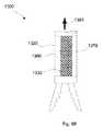
図9Cは、椎骨部1635の分解部品配列図を示す。椎骨部1635は、1つ以上の印刷回路基板1640A、1640Bを含むことができる。椎骨部1635は、椎骨部1635の両側に配された2つの印刷回路基板1640A、1640Bを含むことができる。2つの印刷回路基板1640A、1640Bは、同じものであってよい。2つの印刷回路基板1640A、1640Bは、印刷回路基板1640B上に示されるように、当該印刷回路基板の一方の側に加熱素子1641を含むことができる。2つの印刷回路基板1640A、1640Bは、印刷回路基板1640A上に示されるように、当該印刷回路基板の他方の側には諸部品を含むことができる。これらの部品には、スイッチ1655(例えば、アドレス可能マイクロスイッチ)を含めることが可能である。スイッチ1655は、どの椎骨部をオンするかを選択する。これらの部品は、加熱素子1641をオン、オフするためのリレーまたはFET1660を含み得る。FETのリレー1660は、加熱素子1641に対する電源を提供する。他の諸実施形態において、低融点固体の代わりにまたはこれに加えて、静電気効果または磁気効果に基づく他の硬化メカニズムを用いることも可能である。1つ以上の電気ワイヤ(図示せず)は、この2つの印刷回路基板1640A、1640Bを、様々な他の機能のため(例えば、電力、データ伝送)他の部品に接続する。スイッチ1655およびリレー1660は、1つの部品に組み合わせることができる。スイッチ1655および/またはリレーまたはFET1660は、既存技術で知られた、素子を活性化/非活性化するための他のメカニズムで代替することが可能である。 FIG. 9C shows an array of disassembled parts of the
椎骨部1635は、球体スペーサボール1646を含むことができる。球体スペーサボール1646は、ボールシート1645A、1645B中に保持することが可能である。ボールシート1645A、1645Bは、印刷回路基板1640A、1640Bに結び付けることができる。ボールシート1645A、1645Bは、各ボールを挟んで所定の距離を維持することが可能である。椎骨部1635は、スペーサ1650を含むことができる。スペーサ1650は、固体状態および液体状態の両方を有する低融点材料(例えば金属)で形成することが可能である。固体状態と液体状態との間の転移は、低温(例えば、150°Fより低い、140°Fより低い、130°Fより低い、120°Fより低い、110°Fより低い、100°Fより低い、90°Fより低いなど)で生じる。スペーサ1650は、室温で固体とすることができる。この低融点材料は、保持器によってカプセル化することが可能である(例えば、低融点材料の周りに注型されたシリコン)。スペーサ1650は、2つの印刷回路基板1640A、1640Bの間に配置されることができる。球体スペーサボール1646は、スペーサ1650内に保持される。 The
ツール1600を位置付けるために、データ信号は、選択された椎骨部の2つの印刷回路基板1640A、1640Bに送信される。このデータ信号は、1つの選択された椎骨部1635または複数の選択された椎骨部1635に送信することができる。このデータ信号は、選択された椎骨部1635の加熱素子1641のペアを活性化させる。選択された椎骨部1635中の2つの印刷回路基板1640A、1640Bの間に屈曲を生成するために、および/または任意の角度方位が得られるように、制御ケーブル1620A、1620B、1620Cに張力を加えることができる。 To position the
データ信号によって、選択された椎骨部1635の加熱素子1641のペアを非活性にすることが可能である。これにより加熱素子1641は、オフにされ、低融点材料が制御ケーブル1620A、1620B、1620Cによって設定された方位(例えば、位置および/または角度)で凝固することを可能にする。一実施形態において、制御ケーブル1620A、1620B、1620Cは、低融点材料が凝固するまで選択された椎骨部1635の位置および/または角度を維持することができる。いくつかの実施形態において、低融点材料の凝固および/または冷却を加速するために、器具用チャネル1630を通して冷却材を送ることも可能である。選択された椎骨部1635および選択された椎骨部1635のグループの角度を動かして設定することによって、図9Bに示されるように、複合湾曲を実現することが可能である。 The data signal allows the pair of
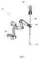
ここでは、手術システムのために有益ないくつかの概念を説明しているが、これらの概念は、手術外および非医療応用においても利点を提供することができる。図10は、外科手術(例えば、経皮的最小侵襲性の外科手術)を実施するのに用いることが可能な高操作性手術システム(hyperdexterous surgical system)5を示す。この高操作性手術システム5は、1つ以上の高操作性手術アーム10を含むことができる。いくつかの実施形態において、外科手術は、ツール(例えば本明細書に記載されたツールのいずれか)を操作して、例えば、高操作性手術アーム10に保持されたツールを操作して実施される。 Although some concepts that are useful for surgical systems are described here, these concepts can also provide benefits in non-surgical and non-medical applications. FIG. 10 shows a hyperdexterous
図11は、高操作性手術アーム10の或る実施形態を示す。高操作性手術アーム10は、高操作性手術ツール30’に連結することができる。このツールは、「高操作性手術ツール」または代わりに単に「ツール」と呼ぶことにする。高操作性手術ツール30’は、遠位端部31’および近位端部32’を含む。一実施形態において、高操作性手術ツール30’および遠位端部31’は、図1A〜図3B中のツール30および遠位端部31と同様であり得る。使用において、遠位端部31’は、(例えば、経皮的最小侵襲性の外科手術において)切開点を通して患者の体内に配置されることができる。ツール30’の遠位端部31’は、エンドエフェクタ(例えば、図1A中の捕捉具310などの捕捉具)を含むことが可能である。エンドエフェクタは、実施対象の外科手術またはタスクに基づいて選択することができる。ツール30’の遠位端部31’は、手首部を含むことが可能であり、その詳細については本明細書でさらに説明する。図1A中のツール310などのツールの手首部の改良された設計についてのいくつかの概念を上記で説明した。ここでは、手術システムのために有益ないくつかの概念を説明するが、これらは、手術システム以外にも同様に適用することができよう。 FIG. 11 shows an embodiment of the highly manipulable
高操作性手術システム5および高操作性手術アーム10は、共同所有、同時係属の、2014年3月13日出願の国際特許出願第PCT/US2014/26115号、2013年3月15日出願の米国仮特許出願第61/791248号、2013年11月20日出願の米国仮特許出願第61/906802号、2013年11月26日出願の米国仮特許出願第61/908888号、2013年12月12日出願の米国仮特許出願第61/915403号、および2014年2月5日出願の米国仮特許出願第61/935966号にさらに記載されており、これらの全ては、ここで参照することにより本明細書に組み込まれ、本明細書の一部と見なすものとする。 The High
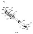
図12Aは、ツールの別の実施形態を示す。このツール400は、図1A〜図3B中に示されたツール30と実質的に同様とすればよい。ツール400は、ツール400の遠位端部31’の手首部402を有することが可能で、手首部402は、エンドエフェクタ410をツール400のシャフト30Aに連結している。この図示の実施形態において、手首部402は、プーリ440A、440B、450A、450B、425A、425B、427A、427B、420A、および420Bを含むことができる。プーリ440A、450Aは、第1セットに配置される。プーリ440B、450Bは、第2セットに配置される。プーリ420A、420Bは、第3セットに配置される。プーリ425A、427Aは、第4セットに配置される。プーリ425B、427Bは、第5セットに配置される。プーリ420A、420Bの第3セットは、図3Aに関連して前述したプーリ320A、320Bの第3セットと実質的に同様であり、それぞれ、エンドエフェクタ410の顎410A、410Bに連結する。同じように、プーリ440A、450Aの第1セット、およびプーリ440B、450Bの第2セットは、図3Aに関連して前述したプーリ340B、350Bの第1セット、およびプーリ340A、340Bの第2セットと実質的に同様である。ツール400は、該ツールがプーリの2つの追加セット、プーリ425A、427Aの第4セットおよびプーリ425B、427Bの第5セットを含むという点で、図3Aのツール30とは異なる。 FIG. 12A shows another embodiment of the tool. The
図12Bに示されるように、プーリ425A、427Aの第4セット、およびプーリ425B、427Bの第5セットは、プーリ440A、450Aの第1セット、およびプーリ440B、450Bの第2セットに対し角度が付けられる。プーリ425Aの回転軸は、プーリ440Aの回転軸に対して角度が付けられる。プーリ427Aの回転軸は、プーリ450Aの回転軸に対して角度が付けられる。プーリ425Bの回転軸は、プーリ440Bの回転軸に対して角度が付けられる。プーリ427Bの回転軸は、プーリ450Bの回転軸に対して角度が付けられる。 As shown in FIG. 12B, the fourth set of
図12Cを参照すると、プーリ425A、427Aの第4セットは、角度付きくさび具426Aによって維持されており、該くさび具は、相互に角度付けされた(例えば、15°、30°、45°など)2つの軸棒452A、452Bを含むことができる。角度付き軸棒452A、452Bは、プーリ425A、427Aが軸棒452A、452Bの周りを回転できるように、該軸棒上にプーリ425A、427Aの第4セットを支えている。図12Bに最良に示されているように、同様な仕方で、角度付きくさび具426Bによって或る角度でプーリ425B、427Bの第5セットを維持することができる。角度付きくさび具426Bは、角度付きくさび具426Aと実質的に同様である。図12A〜図12Cに示され、そして前に説明したように、手首部402のこの設計は、手首部402の諸プーリの周りにルートされるケーブル間の交差および摩擦を減少させて、したがって、ケーブルのルーティングをさらに有利にする。手首部402のケーブルのルーティングについては、以下でさらに説明する。 Referring to FIG. 12C, a fourth set of
ツール400は、顎410A、410Bを、(例えば、プーリ420A、420Bを介して、両顎を別々に回転させて)捕捉させる、(例えば、プーリ420A、420Bを介して、両顎を一緒に回転させて)ヨーイングさせる、および(例えば、両顎をプーリ440A、450A、440B、450Bの周りに回転させて)ピッチさせるなど、様々な仕方で動くよう作動させることができる。図13Aは、ツール400の手首部402中の第1ケーブル490Aのルーティングを示す。第1ケーブル490Aは、ツール400の近位端部(図示せず)から始まり、図3A中に示されたツール30に関連して前述したのと同様な仕方で、ツールシャフト30Aを通って、(例えば、開口または穴を通るなど、シャフト30Aの端部に取り付けられたヨークを通って、)ツールシャフト30Aの外に延びる。この図示の実施形態において、第1ケーブル490Aは、プーリ440A、450Aの第1セット中の1つのプーリの周りに少なくとも部分的に巻き付く。第1ケーブル490Aは、次いで、プーリ425A、427Aの第4セット中の1つのプーリの周りに少なくとも部分的に巻き付く。第1ケーブル490Aは、その後、プーリ420A、420Bの第3セット中の1つのプーリの周りに少なくとも部分的に巻き付く。前の諸実施形態で説明したように、第1ケーブル490Aは、プーリ420A、420Bの第3セット中の1つのプーリ内に保持されたビードに連結することができる(例えば、図3A中のビード315Aのようなビードに固定的に連結される)。第1ケーブル490Aは、次いで、プーリ425B、427Bの第5セット中の1つのプーリの周りに少なくとも部分的に巻き付き、その後、第1ケーブル490Aは、プーリ440B、450Bの第2セット中の1つのプーリの周りに少なくとも部分的に巻き付く。第1ケーブル490Aは、その後、ツール400の近位端部の方へツールシャフトを通って延びる。いくつかの実施形態において、第1ケーブル490Aは、図13Aに示されるように、プーリ450A、427A、420A、425B、および440Bの周りに少なくとも部分的に巻き付く。
この図示の実施形態において、プーリ440A、440B、425A、425Bは、外側プーリと見なされ、プーリ450A、450B、427A、427Bは、内側プーリと見なされる。いくつかの実施形態において、第1ケーブル490Aは、2つの外側プーリ(例えば、440B、425B)および2つの内側プーリ(例えば、450A、427A)の周りに巻き付いている。第1ケーブル490Aのルーティングをより明瞭に表すために、図13Aでは、第1ケーブル490Aは、プーリから僅かにずらして示されている。 In this illustrated embodiment, the
図13Bは、ツール400の手首部402中の第2ケーブル490Bのルーティングを示す。第2ケーブル490Bは、プーリ440A、450Aの第1セット中の1つのプーリの周りに少なくとも部分的に巻き付く。第2ケーブル490Bは、次いで、プーリ425A、427Aの第4セット中の1つのプーリの周りに少なくとも部分的に巻き付く。第2ケーブル490Bは、その後、プーリ420A、420Bの第3セット中の1つのプーリの周りに少なくとも部分的に巻き付く。前の諸実施形態で説明したように、第2ケーブル490Bは、プーリ420A、420Bの第3セット中の1つのプーリ内に保持されたビードに連結することができる(例えば、ビード315Aのようなビードに固定的に連結される)。第2ケーブル490Bは、次いで、プーリ425B、427Bの第5セット中の1つのプーリの周りに少なくとも部分的に巻き付き、その後、第2ケーブル490Bは、プーリ440B、450Bの第2セット中の1つのプーリの周りに少なくとも部分的に巻き付く。第2ケーブル490Bは、その後、ツール400の近位端部の方へツールシャフト30Aを通って延びる。いくつかの実施形態において、第2ケーブル490Bは、図13Bに示されるように、プーリ450B、427B、420B、425A、および440Aの周りに少なくとも部分的に巻き付く。 FIG. 13B shows the routing of the
いくつかの実施形態において、第2ケーブル490Bは、2つの外側プーリ(例えば、440A、425A)および2つの内側プーリ(例えば、450B、427B)の周りに少なくとも部分的に巻き付く。第2ケーブル490Bのルーティングをより明瞭に表すために、図13Bでは、第2ケーブル490Bは、プーリから僅かにずらして示されている。 In some embodiments, the
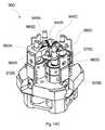
図14Aは、本明細書で説明した諸ツールに組み込みが可能な、ツールの近位端部の或る実施形態を示す。この近位端部は、モータパック800を含む。この図示の実施形態において、モータパック800は、前に説明したような、4つの別個のケーブルを駆動する4つのモータ(例えば電気モータ)を含む。 FIG. 14A shows an embodiment of the proximal end of a tool that can be incorporated into the tools described herein. This proximal end includes the
いくつかの実施形態において、該4つのケーブルの各々は、モータパック800の1つのモータによって別々に制御される。有利には、4つのケーブルの各々は、モータパック800の1つのモータによって別々に制御される、モータパック800を備えるツールは、モータがケーブル中の一切のたるみを除去するので、事前引張を必要としない。事前引張は、ケーブル−プーリシステムにおいてケーブルがプーリと相互作用をする際にスリップを生じさせ得るケーブルの弾力特性に起因して必要となる。したがって、市販のツールは、当該設計または他のやり方によって事前引張を補っている。図5A〜図6Dで説明したケーブル駆動の方法では、ケーブルを駆動するのに必要なモータは3つだけであるが、これらのシステムは、事前引張を必要とし得るケーブルループを用いている。 In some embodiments, each of the four cables is separately controlled by one motor in the
引き続き図14Aを参照すると、モータパック800は、モータハウジング840を含むことができる。モータパック800は、モータハウジング840内に4つのモータを保持することが可能であり、図14Aでは、モータ810A、810Bの2つだけが見えている。これら4つのモータ810A、810B、810C(図示せず)、810D(図示せず)は、それぞれ、ギアボックス815A、815B、815C(図示せず)、815D(図示せず)に関連付けることができる。各モータ810A、810B、810C、810Dは、スピンドル820などのスピンドルと関連付けることができて、各スピンドル820は、はめ合いインターフェース830(例えば、正方形開口部、六角形開口部、スロット)を持つことが可能である。モータ810A、810B、810C、810Dは、ソフトウェアの制御の下に駆動ユニット(図示せず)によって駆動される。モータパック840は、図11中に示されたツール30のまたは本明細書で説明した任意の他のツールの近位端部32などのツールの近位端部に取り付けることができる。 Continuing with reference to FIG. 14A, the
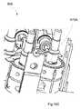
図14Bは、モータパック800に着脱可能に連結可能な結合ユニット900の一実施形態を示す。結合ユニット900は、近位端部906および遠位端部905を含み得る。図14A中に示されたモータパック800の各スピンドル820のはめ合いインターフェース830は、スピンドル910Aなど、結合ユニット900中の対応するスピンドルと、連結しおよび/またははめ合うことができる。図14Bでは、1つのスピンドル910だけが見えるが、結合ユニット900は、モータパック800のはめ合いインターフェース830の各々に対する対応スピンドル(例えば、図14Cに示されるような4つのスピンドル910A、910B、910C、910D)を有することができる。一実施形態において、結合ユニット900は、使い捨てとすることが可能である。別の実施形態において、結合ユニット900、ツールシャフト、手首部、およびエンドエフェクタを含めて、モータパック800から遠位の一切の部品を使い捨てにすることができる。したがって、モータパック800は、通常、ツールの比較的高価な部分であり、これは、再使用可能とすることができる。というのは、結合ユニット900は、ツールの近位部分に組み込むことが可能で、容易に取り外して、新しい結合ユニット900および関連するツールシャフト、手首部、およびエンドエフェクタに置き換えることが可能だからである。この設計は、無菌バリヤを有利に提供する。すなわち、結合ユニット900を含めて、モータハウジング840より遠位のあらゆるものを無菌にすることが可能であり、結合ユニット900は、無菌バリヤを少なくとも部分的に提供することができる。モータハウジング840、モータ810A、810B、810C、810D、および/またはモータパック800内に配置された一切の部品は、非殺菌としておくことが可能である。 FIG. 14B shows an embodiment of a
図14B〜図14Dは、結合ユニット900をさらに示す。一実施形態において、スピンドル910A、910B、910C、910Dは、近位端部906から結合ユニット900を通ってその遠位端部905に延びる。結合ユニット900は、4つのプーリ940A、940B、940C、940Dを含むことができる。結合ユニット900は、図14Cに示されるように、スピンドル910A、910B、910C、910D上に搭載された4つのスプール945A、945B、945C、945Dを含むことが可能である。プーリ940A、940B、940C、940Dは、スプール945A、945B、945C、945Dにケーブルを供給することができる。スプール945A、945B、945C、945Dは、図12A中の手首部402および顎410A、410Bなど、ツールの手首部および/または顎を駆動する他の部品にケーブルを供給することが可能である。また、スプール945A、945B、945C、945Dは、ケーブル中のたるみを取り去ることができる。プーリ940A、940B、940C、940Dは、図14Dに最良に示されているように、ヨーク950A、950B(図示せず)、950C(図示せず)、950D(図示せず)上に搭載することができる。 14B-14D further show the
ここで図14Dを参照すると、ヨーク950Aだけが示されているが、前述のように、プーリ940A、940B、940C、940Dの各々をヨーク950Aと類似のヨークに搭載することが可能である。ヨーク950Aは、プーリ940Aに連結することができる。ヨーク950B、950C、および950Dは、プーリ940B、940C、および940Dに連結することが可能である。ヨーク940A、940B、940C、940Dは、ロードセル960A、960B、960C、960Dに連結することができて、ロードセル960A、960B、960C、960Dは、結合ユニット900に連結することができる。 Although only the
各ケーブル端は、プーリ940A、940B、940C、940Dの1つの周りにルートされ、スプール945A、945B、945C、945Dの周りに少なくとも部分的に巻き付く。スプール945A、945B、945C、945Dの周りに巻き付いた後、ケーブル端は、スプール945A、945B、945C、945Dに固定される。一実施形態において、スプール945A、945B、945C、945Dの各々は、図14E中に最良に示されている終端治具975Aなどの終端治具(例えばノッチ)を含むことができる。図14Eには、1つの終端治具975Aだけが示されているが、スプール945A、945B、945C、945Dの各々は、終端治具を有することが可能である(例えば、スプール945B、945C、945Dは、図示されていないが、終端治具975Aと同様な終端治具975B、975C、975Dを有することが可能である)。各ケーブル端は、該ケーブル端が対応するスプール945A、945B、945C、945Dから外れるのを防止するために、終端治具975A、975B、975C、975D内に保持することができる。一実施形態において、ケーブル端は、終端治具の形状に対応する形状を有することが可能である。 Each cable end is routed around one of the
図14Dを参照すると、ロードセル960A、960B、960C、960Dは、1つ以上のセンサを含むことができる。例えば、一実施形態において、各ロードセル960A、960B、960C、960Dは、力センサ970A、970B、970C、970Dを含むことが可能である。力センサ970A、970B、970C、970Dは、ケーブルの張力を測定することができる。ケーブルに張力がかかると、プーリ940A、940B、940C、および940Dは、力をロードセル960A、960B、960C、960Dに転移する。この力は、ロードセル960A、960B、960C、960Dを曲げることができ、前記曲げを測定して、張力の測定値に変換することが可能である。力センサ970A、970B、970C、970Dによる測定値の出力は、ツールの操作者に触覚供給バックを提供することができる。例えば、力センサによる測定値の出力を手術医に対する触覚供給バックに変換し、ツールの顎(例えば、ツール400の顎410A、410B)の把持力の感覚を与えることが可能である With reference to FIG. 14D, the
図15は、ツールの別の実施形態を示す。このツール1200には、プーリの代わりに椎骨部を用いる、手首部1202を含めることができる。椎骨部を用いる市販のツールは、ツールの手首部の屈曲を制御するためにケーブルループを利用する。これに対して、ツール1200は、手首部1202の姿勢を制御するために、ケーブルループの代わりに独立したケーブル群を用いることができる。ツール1200のこの配置の利点には、ケーブルの事前引張、および長さの精密な制御が不要なことが含まれる。 FIG. 15 shows another embodiment of the tool. The
ツール1200の手首部1202は、1つ以上の椎骨部1220A、1220B、1220Cを含むことができる。3つの椎骨部1220A、1220B、1220Cが図示されているが、ツール1200は、もっと多くのまたはもっと少ない椎骨部(例えば、1つ、2つ、3つ、4つ、5つ、6つの椎骨部など)を含むことが可能である。椎骨部1220Aは、ツールシャフト1210に連結することができる。椎骨部1220A、1220B、1220Cは、1つ以上のジョイント1240(例えば、ボールとソケットとのジョイント)を介して、他の椎骨部および/またはツール1200の他の部品と連結することが可能である。この図示の実施形態において、図15中に示されるように、椎骨部1220A、1220B、1220Cは、ツール1200の遠位端部に連結することができる。但し、他の実施形態において、1つ以上の椎骨部1220A、1220B、1220Cをツール1200の長手方向長沿いの任意の位置に配置することも可能である。 The
引き続き図15を参照すると、ツール1200は、1つ以上の独立したケーブル1230A、1230B、1230Cを含むことができ、これらは、ツールシャフト1210を通って延びる。3つのケーブル1230A、1230B、1230Cが示されているが、ツール1200は、もっと多くのまたはもっと少ないケーブル(例えば、1つ、2つ、3つ、4つ、5つ、6つのケーブルなど)を含むことが可能である。一実施形態において、エンドエフェクタ1250を駆動するために追加のケーブルを使用することができる。各ケーブル1230A、1230B、1230Cは、モータ1260A、1260B、1260Cによって別々に駆動される。ツール1200ではケーブルループは使われないので、この設計は、前述した利点(例えば、ケーブルの事前引張が必要ない)を有する。 Continuing with reference to FIG. 15, the
ケーブル1230A、1230B、1230Cは、1つ以上の椎骨部1220A、1220B、1220Cを通って延びることができる。この図示の実施形態において、ケーブル1230A、1230B、1230Cは、1つ以上の係合メカニズム1270(例えば、ケーブルに圧着され、椎骨部中のポケットの内部に配置された、図3A中のビード315Aと類似のビード)を介して椎骨部1220A、1220B、1220Cに連結することができる。ケーブル1230A、1230B、1230Cに張力がかかると、その張力は、係合メカニズム1270を介して椎骨部1220A、1220B、1220C(1220C)に転移される。ツールの部品(例えば、椎骨部1220A、1220B、1220C)は、シース(図示せず)で覆うことができる。様々な他の椎骨部とケーブルとの設計が可能である。各ケーブル端の別々の制御を使って、ピッチおよびヨーを任意に組み合わせてエンドエフェクタ1250を操作することができる。
図16は、ツールの別の実施形態を示す。このツール1700は、図1A〜図3B中に示されたツール30と類似である。いくつかの実施形態において、ツールの手首部から顎の作動を切り離すことは、利点であり得る。例えば、ツールの手首部の作動からエンドエフェクタの作動を切り離すことによって、エンドエフェクタから手首部への(例えば、捕捉具の顎からツールの手首部のプーリへの)負荷の転移を阻止することができる。エンドエフェクタによるかかる手首部への負荷は、手首部の制御を格段に難しくさせ、および/または手首部の思わぬ動作をもたらすことがある。 FIG. 16 shows another embodiment of the tool. This
ツール1700は、手首部1702を有し、1つ以上のプーリ1740および1つ以上のプーリ1750を含む。プーリ1740は、図3A中に示されたプーリ340A、340B、350A、350Bと実質的に同様とすればよい。プーリ1750は、図3A中に示されたプーリ320A、320Bと実質的に同様とすればよい。明瞭化のため、プーリ1740、1750に対するケーブルルーティングは示されていない。
プーリ1740、1750の周りに少なくとも部分的に巻き付いているケーブル(図示せず)に加え、ツール1700は、エンドエフェクタ1760(例えば捕捉具)の顎1760A、1760Bを制御するための1つ以上の追加ケーブル1730を含むことができる。1つのケーブル1730が示されているが、ツール1700は、任意の数のケーブル(例えば、1つ、2つ、3つ、4つ、5つ、6つのケーブルなど)を含むことが可能である。ケーブル1730は、シース1720内に保持することができ、一実施形態において、このシースは、柔軟性のシースとすることができる。この図示の実施形態において、エンドエフェクタ1760(例えば、顎、捕捉具)は、プーリ1750に連結される。ケーブル1730は、プーリ1750の周りに少なくとも部分的に巻き付くことができ、プーリ1750の運動を介して、エンドエフェクタ1760を制御することができる。ケーブル1730は、プーリ1750を介して、エンドエフェクタ1760を制御するための作動メカニズムに連結することが可能である。ケーブル1730を作動する作動メカニズムは、1つ以上のプーリ(例えば、エンドエフェクタ1760のベース近くに配置されたプーリ)とすればよい。この図示の実施形態において、顎1760A、1760Bを含めて、エンドエフェクタ1760は、プーリ1740から切り離され、したがって、有利に、エンドエフェクタ1760は、負荷をプーリ1740に転移しない。すなわち、エンドエフェクタ1760の運動は、プーリ1740の周りに巻き付いたケーブルによってプーリ1740に与えられる運動から独立している。 In addition to cables (not shown) that are at least partially wrapped around pulleys 1740, 1750,
本明細書の諸実施形態で説明したように、本ツールは、肘部または屈曲部を有することができる。本ツールの制御を維持するために、ユーザ(例えば操作者、手術医)がツールの形状を知ることは、重要であり得る。本明細書に記載したツールの柔軟性セクション(例えば、柔軟性セクション1305)は、1つ以上のセンサ(例えば、複数センサ群)に連結することができ、これらセンサは、ツールの形状に基づいてデータを送信することが可能である。一実施形態において、このデータは、リアルタイムとすることができる。このデータは、有線または無線接続を介して送信することが可能である。 As described in embodiments herein, the tool can have elbows or bends. In order to maintain control of the tool, it may be important for the user (eg operator, surgeon) to know the shape of the tool. The flexibility section of the tool described herein (eg, flexibility section 1305) can be coupled to one or more sensors (eg, multiple sensor groups), which sensors are based on the shape of the tool. It is possible to send data. In one embodiment, this data can be in real time. This data can be transmitted over a wired or wireless connection.
これら1つ以上のセンサは、様々な種類のセンサ(例えば、歪みセンサ、ポジションセンサ)を含み得る。この1つ以上のセンサは、ツールおよび/または柔軟性セクション上またはその内部の任意の箇所に配置されることができる(例えば、ツールの長さ沿いに連結する、柔軟性コアに連結する、椎骨部に連結するなど)。これらのセンサは、様々な技法(例えば、生体適合性の膠または接着剤)を用いてツールに連結することが可能である。 These one or more sensors may include various types of sensors (eg, strain sensors, position sensors). The one or more sensors can be placed anywhere on or within the tool and / or flexibility section (eg, connecting along the length of the tool, connecting to the flexibility core, vertebrae). Connect to the part, etc.). These sensors can be attached to the tool using a variety of techniques (eg, biocompatible glue or glue).
いくつかの実施形態において、柔軟性セクションの形状を計算する間接的方法を用いることが可能である。例えば、屈曲をもたらすケーブルの張力をモニタすることができる。屈曲を生じさせる役割をするケーブルの各々の相対的な張力が分かれば、屈曲を推定することができる。柔軟性セクションが屈曲されている間、当該柔軟性セクションを押圧する外部の力が存在しなければ、屈曲を生じさせるケーブル上の張力のこのようなモニタリングによって該屈曲の形状の推定を提供することが可能である。この推定をセンサからのデータと組み合わせて、ツールの形状(例えば屈曲)の推定を向上することができる。 In some embodiments, it is possible to use an indirect method of calculating the shape of the flexibility section. For example, the tension of the cable that results in bending can be monitored. Bending can be estimated if the relative tension of each of the cables responsible for causing bending is known. Such monitoring of the tension on the cable that causes the flexion should provide an estimate of the shape of the flexion if there is no external force pressing against the flexible section while the flexible section is flexed. Is possible. This estimation can be combined with data from the sensor to improve the estimation of the shape (eg, bending) of the tool.
いくつかの実施形態において、ツールの形状をカメラでモニタすることが可能である。このカメラは、患者の体腔の中に挿入されたカメラとすればよい。このカメラは、ユーザを助力するため任意の場所に位置させることが可能である。カメラは、ツールに関するデータ(例えば画像)を処理ユニット(例えば、高操作性手術システム5の処理ユニット)に送信することができる。該処理ユニットは、画像をさらに処理し、ツールの柔軟性セクションを認識するためパターン認識技法を用いることが可能である。柔軟性セクションが認識されたならば、画像に基づいて屈曲のパラメータを計算することができる。これらのパラメータは、ツールの制御を維持する役割をする主処理ユニットに送信することが可能である。 In some embodiments, it is possible to monitor the shape of the tool with a camera. This camera may be a camera inserted into the patient's body cavity. The camera can be positioned anywhere to assist the user. The camera can transmit data (eg, images) about the tool to a processing unit (eg, the processing unit of the highly manipulable surgical system 5). The processing unit can further process the image and use pattern recognition techniques to recognize the flexibility section of the tool. Once the flexibility section is recognized, the flexion parameters can be calculated based on the image. These parameters can be sent to the main processing unit, which is responsible for maintaining control of the tool.
図17Aは、ツールの別の実施形態を示す。このツール1800は、手首部1802を有することができ、ハウジング1811を含むことができる。図17B〜図17Cは、ハウジング1811を取り除いたツール1800を示す。ツール1800は、顎1810A、1810Bのペアを備えたエンドエフェクタ1810を含むことができる。エンドエフェクタの他の実施形態を使うことも可能である。ツール1800は、図17B中に示されるように、様々なプーリを含むことができる。 FIG. 17A shows another embodiment of the tool. The
プーリ1845A、1845Bは、プーリの第1セットとして配置される。プーリ1850A、1850Bは、プーリの第2セットとして配置される。プーリ1845A、1845Bの第1セット、およびプーリ1850A、1850Bの第2セットは、ヨーク1812に連結することができ、該ヨークは、ツールシャフト(図示せず)に連結することができる。また、このツールは、プーリの第3セットとして配置されたプーリ1820A、1820B、1815A、1815Bを含むことが可能である。顎1810A、1810Bは、プーリ1815A、1815B、1820A、1820Bの第3セットに連結することができる。この図示の実施形態において、顎1810Aは、プーリ1815A、1815Bに連結され、顎1810Bは、プーリ1820A、1820Bに連結される。 The
また、ツール1800は、プーリの第4セットとして配置されたプーリ1835A、1835Bを含むことができる。プーリ1835Aの回転中心を、プーリ1835Bの回転中心からオフセットすることが可能である。一実施形態において、プーリ1835Aは、プーリ1835Bよりも小さな直径を有することができる。また、ツール1800は、プーリの第5セットとして配置されたプーリ1840A、1840Bを含むことができる。プーリ1840Aの回転中心を、プーリ1840Bの回転中心からオフセットすることが可能である。プーリ1840Aは、プーリ1840Bよりも小さな直径を有することができる。プーリ1835A、1840Bは、同一の回転軸に配置されることができる。プーリ1835B、1840Aも、同一の回転軸に配置されることができる。プーリ1835A、1840Bの回転中心は、プーリ1845A、1845Bの第1セットおよびプーリ1850A、1850Bの第2セットの回転中心からオフセットすることができる。プーリ1835B、1840Aの回転中心は、プーリ1845A、1845Bの第1セットおよびプーリ1850A、1850Bの第2セットの回転中心からオフセットすることができる。
図17Cを参照すると、プーリ1825A、1825Bは、プーリの第6セットとして配置される。プーリ1830A、1830Bは、プーリの第7セットとして配置される。この図示の実施形態において、プーリ1825A、1830Aは、外側プーリであり、プーリ1825B、1830Bは、内側プーリである。外側プーリ1825A、1830Aの直径は、内側プーリ1825B、1830Bよりも小さくできる。 With reference to FIG. 17C, the pulleys 1825A, 1825B are arranged as a sixth set of pulleys. The
プーリ1825A、1825Bの第6セットおよびプーリ1830A、1830Bの第7セットは、顎1810A、1810Bのペアおよび/またはプーリ1820A、1820B、1815A、1815Bの第3セットに整列させることができる。いくつかの実施形態において、プーリ1820A、1820B、1815A、1815Bは、それぞれ、プーリ1825A、1825B、1830B、1830Aと整列し、これにより、プーリ1820A、1820B、1815A、1815Bとプーリ1825A、1825B、1830B、1830Aとの間で、それぞれ、ケーブルが真っすぐな経路に沿って延びることを可能にし、したがって、ケーブル中の曲がりおよびケーブルとプーリとの間の摩擦を有利に低減する。この配置の他の利点は、以降で説明する。 A sixth set of pulleys 1825A, 1825B and a seventh set of pulleys 1830A, 1830B can be aligned with a pair of
プーリ1815A、1815B、1820A、1820Bの第3セットは、(例えば、ツール1800中の他のプーリに比べて)大きな直径を有することができる。一実施形態において、プーリ1815A、1815B、1820A、1820Bの第3セットは、ツールシャフト(図示せず)の直径ほどの大きさの(例えば、ほぼ等しい)直径を有することが可能である。プーリ1815A、1815B、1820A、1820Bの第3セットは、相互に近接しておよび/または図1A中に示されたツール30のプーリ320A、320Bよりもツールシャフトの中心軸に近接して、配置されることができる。プーリ1815A、1815B、1820A、1820Bの第3セットのこれらの配列および直径のサイズは、ケーブルの信頼性および耐用寿命(例えば、より少ない摩耗および裂傷)を有利に増大する。より大きなプーリは、より大きな直径を有するので、より大きなプーリを行き来するケーブルは、湾曲が少なく、したがって、ポジティブな方向で信頼性に影響する。プーリ1815A、1815B、1820A、1820Bの第3セットのこの配列は、プーリの他のセットの配列とともに、ツール1800の1つ以上のケーブルがより少ない、より低度の急カーブを通ることを確実にし、同様に、ポジティブな方向で、ケーブルの信頼性および耐用寿命に影響する。プーリ1815A、1815B、1820A、1820Bの第3セットのこれらの配列および直径のサイズは、ケーブルがより少なくより低度の急カーブを通り、これによってより大きな力を顎にかけることができるので、図1A中に示されたプーリ320A、320Bよりも大きな力を顎に加えるようにアレンジされる。 A third set of pulleys 1815A, 1815B, 1820A, 1820B can have a larger diameter (eg, compared to other pulleys in the tool 1800). In one embodiment, the third set of pulleys 1815A, 1815B, 1820A, 1820B can have a diameter as large as (eg, approximately equal) the diameter of the tool shaft (not shown). A third set of pulleys 1815A, 1815B, 1820A, 1820B is located closer to each other and / or closer to the central axis of the tool shaft than the
ツール1800は、顎1810A、1810Bを、(例えば、プーリ1815A、1815B、1820A、1820Bを介して、両顎を別々に回転させて)捕捉させる、(例えば、プーリ1815A、1815B、1820A、1820Bを介して、両顎を一緒に回転させて)ヨーイングさせる、および(例えば、ヨーク1812を介して軸1813の周りに回転させて)ピッチさせるなど、様々な仕方で動くよう作動させることができる。図17D〜図17Eは、ツール1800の第1ケーブル1855Aのケーブルルーティングを示す。他の諸実施形態で前に説明したように、ヨーク1812および/または顎1810A、1810Bの1つまたは両方の運動をもたらすために、4つのケーブルを別々に制御することができる。各ケーブル端のこの別々の制御によって、手首部1802(図17A参照)およびエンドエフェクタ1810のより正確な動作を提供することができる。図17D〜図17Eのケーブルルーティングは、顎1810Aを制御する。ツール1800は、(本明細書に記載した390A’、390A”、390B’、390B”と同様に)4つのケーブル端を有する4つのケーブルを用いる。
図17Dを参照すると、第1ケーブル1855Aは、ツールシャフト(図示せず)から始まる。第1ケーブル1855Aは、プーリ1845A、1845Bの第1セット中の1つのプーリの周りに少なくとも部分的に巻き付く。第1ケーブル1855Aは、次いで、プーリ1835A、1835Bの第4セット中の1つのプーリの周りに少なくとも部分的に巻き付く。第1ケーブル1855Aは、その後、プーリ1825A、1825Bの第6セット中の1つのプーリの周りに少なくとも部分的に巻き付く。第1ケーブル1855Aは、次に、プーリ1815A、1815B、1820A、1820Bの第3セット中の1つのプーリの周りに少なくとも部分的に巻き付く。いくつかの実施形態において、第1ケーブル1855Aは、図17D中に示されるように、プーリ1845A、1835A、1825B、1820Bの周りに少なくとも部分的に巻き付く。ケーブル1855Aは、プーリ1820Bに(図3A中のビード315Aなど、プーリのポケット中に保持されたビードへの圧着によって)固定的に連結することができる。いくつかの実施形態において、第1ケーブル1855Aは、内側プーリ1820B、1825Bおよび外側プーリ1835A、1845Aの周りに少なくとも部分的に巻き付く。 With reference to FIG. 17D, the
図17Eを参照すると、第2ケーブル1855Bは、ツールシャフト(図示せず)から始まる。第2ケーブル1855Bは、プーリ1850A、1850Bの第2セット中の1つのプーリの周りに少なくとも部分的に巻き付く。第2ケーブル1855Bは、次いで、プーリ1840A、1840Bの第5セット中の1つのプーリの周りに少なくとも部分的に巻き付く。第2ケーブル1855Bは、その後、プーリ1825A、1825Bの第6セット中の1つのプーリの周りに少なくとも部分的に巻き付く。第2ケーブル1855Bは、次に、プーリ1815A、1815B、1820A、1820Bの第3セット中の1つのプーリの周りに少なくとも部分的に巻き付く。いくつかの実施形態において、第2ケーブル1855Bは、図17E中に示されるように、プーリ1850B、1840B、1825A、1820Aの周りに少なくとも部分的に巻き付く。いくつかの実施形態において、第2ケーブル1855Bは、外側プーリ1820A、1825Aおよび内側プーリ1840B、1850Bの周りに少なくとも部分的に巻き付く。 With reference to FIG. 17E, the second cable 1855B begins at the tool shaft (not shown). The second cable 1855B wraps at least partially around one pulley in the second set of pulleys 1850A, 1850B. The second cable 1855B then wraps at least partially around one pulley in the fifth set of pulleys 1840A, 1840B. The second cable 1855B then wraps at least partially around one pulley in the sixth set of pulleys 1825A, 1825B. The second cable 1855B then wraps at least partially around one pulley in the third set of pulleys 1815A, 1815B, 1820A, 1820B. In some embodiments, the second cable 1855B wraps at least partially around the
図17D〜図17Eを参照すると、1つのケーブルだけが作動または張力付加されると、顎は、一方向に回転し、他方のケーブルが作動または張力付加されると、顎は、反対方向に回転することになる。さらに、ケーブル上に加える張力の量によって、顎1810A、1810Bの位置を制御することができる。例えば、図17D中に示されたケーブル1855Aには、矢印線1860の方向に張力がかかり、ケーブル1855Bは、緩められる。顎1810Aは、したがって、矢印線1862の方向に動くことになる。上記の代わりに、ケーブル1855Bに矢印線1865の方向に張力がかかると、顎1810Aは、矢印線1867の方向に動くことになる。両方のケーブルに同時に張力がかかると、プーリ1815A、1815B、1820A、1820Bの第3セットは、回転しない。代わりに、プーリ1815A、1815B、1820A、1820Bの第3セットは、矢印線1870にように、紙面平面の中側への(すなわち、図17A中に示されたヨーク1812の軸1813の周りの)運動で動く。 Referring to FIGS. 17D-17E, when only one cable is actuated or tensioned, the jaw rotates in one direction, and when the other cable is actuated or tensioned, the jaw rotates in the opposite direction. Will be done. Further, the positions of the
ケーブルの別のペアを、ケーブル1855A、1855Bが顎1810Aに連結されているのと同様な仕方で、顎1810Bに連結することができる。顎1810Bに取り付けられた前記他のケーブルのセットを引っ張るアクションについては、ケーブル1855A、1855Bについて上記で説明したのと同様なので説明しない。上記の説明から、一実施形態における、顎1810A、1810Bの運動は、4つの独立したケーブルを使ってどのように制御できるかが分かる。 Another pair of cables can be connected to
図18Aは、ツールの別の実施形態を示す。このツール1900は、手首部1902、および2つの顎1901A、1901Bを含む、エンドエフェクタ1901を有することができる。ツール1900には、ツールシャフト1915に連結されたヨーク1910を含めることが可能である。図18Bは、取り外されたヨーク1910を示す。ツール1900は、プーリ1930A、1930Bの第1セットを含むことができる。また、ツール1900は、プーリ1935A、1935Bの第2セットを含むことができる。プーリ1930A、1930Bの第1セットの回転軸は、プーリ1935A、1935Bの第2セットの回転軸と整列させることが可能である。ツール1900は、プーリ1905A、1905Bの第3セットを含むことができる。顎1901A、1901Bは、プーリ1905A、1905Bの第3セットに連結することが可能である。 FIG. 18A shows another embodiment of the tool. The
ツール1900は、プーリ1920A、1920Bの第4セット、およびプーリ1925A、1925Bの第5セットを含むことができる。プーリ1920A、1920Bの第4セットは、ツール1900の一方側に配置されることができ、プーリ1925A、1925Bの第5セットは、ツール1900の他方側に配置されることができる。プーリ1920A、1920Bの第4セットの回転軸は、プーリ1925A、1925Bの第5セットの回転軸と整列させることが可能である。
ツール1900は、プーリ1910A、1910Bの第6セット、およびプーリ1915A、1915Bの第7セットをさらに含むことができる。プーリ1910A、1910Bの第6セットは、ツール1900の一方側に配置されることができ、プーリ1915A、1915Bの第7セットは、ツール1900の他方側に配置されることができる。プーリの第6セットと第7セットとは、プーリ1910A、1910Bの第6セットの回転中心がプーリ1915A、1915Bの第7セットの回転中心からオフセットされているので、相オフセットされたプーリである。
ツール1900は、顎1905A、1905Bを、(例えば、プーリ1905A、1905Bを介して、両顎を別々に回転させて)捕捉させる、(例えば、プーリ1905A、1905Bを介して、両顎を一緒に回転させて)ヨーイングさせる、および(例えば、両顎を図18A中の紙面平面の中側に示された、ヨーク1910の軸1913の周りに回転させて)ピッチさせるなど、様々な仕方で動くよう作動させることができる。図18Dは、第1ケーブル1950Aおよび第2ケーブル1950Bのルーティングを示す。明瞭化のため、第1ケーブル1950Aは、点線で示され、第2ケーブル1950Bは、実線で示されている。第1ケーブル1950Aは、ツールシャフト1915から始まる。第1ケーブル1950Aは、プーリ1930A、1930Bの第1セット中の1つのプーリの周りに少なくとも部分的に巻き付く。第1ケーブル1950Aは、次いで、プーリ1920A、1920Bの第4セット中の1つのプーリの周りに少なくとも部分的に巻き付く。第1ケーブル1950Aは、その後、プーリ1910A、1910Bの第6セット中の1つのプーリの周りに少なくとも部分的に巻き付く。第1ケーブル1950Aは、次に、プーリ1905A、1905Bの第3セット中の1つのプーリの周りに少なくとも部分的に巻き付く。いくつかの実施形態において、第1ケーブル1950Aは、プーリ1905A、外側プーリ1910A、外側プーリ1920A、および外側プーリ1930Aの周りに少なくとも部分的に巻き付く。ケーブル1950Aは、プーリ1905Aに(図3A中のビード315Aなど、プーリのポケット中に保持されたビードへの圧着によって)固定的に連結することができる。
また、第2ケーブル1950Bも、ツールシャフト1915から始まる。第2ケーブル1950Bは、プーリ1930A、1930Bの第1セット中の1つのプーリの周りに少なくとも部分的に巻き付く。第2ケーブル1950Bは、次いで、プーリ1920A、1920Bの第4セット中の1つのプーリの周りに少なくとも部分的に巻き付く。第2ケーブル1950Bは、その後、プーリ1905A、1905Bの第3セット中の1つのプーリの周りに少なくとも部分的に巻き付く。いくつかの実施形態において、第2ケーブル1950Bは、プーリ1905B、外側プーリ1910A、内側プーリ1920B、および内側プーリ1930Bの周りに少なくとも部分的に巻き付く。第2ケーブル1950Bは、プーリ1910A、1910Bの第6セット中の1つのプーリの周りには巻き付かない。ケーブル1950Bは、プーリ1905Bに(図3A中のビード315Aなど、プーリのポケット中に保持されたビードへの圧着によって)固定的に連結することができる。ケーブル1950A、1950Bは、ツール1900の近位端部の方へ延びる。 The
顎1910Aは、プーリ1905Aに連結され、顎1901Bは、プーリ1905Bに連結される。第1ケーブル1905Aは、プーリ1905Aに連結して、顎1901Aを制御することができる。第2ケーブルは、プーリ1905Bに連結して、顎1901Bを制御することができる。ケーブルの別のペア(1905C、1905D)は、プーリ群の反対側に沿って延びて、プーリ1905Aおよび1905Bに連結することができ、それらのケーブルルーティングは、該ケーブルがプーリ1915A、1915Bの周りに少なくとも部分的に巻き付くようになっていることを除けば、図18D〜図18E中に示されたのと同じ構成を有することになろう。いくつかの実施形態において、ケーブル1905Aと1905Cとは一体であり、単一のケーブルを形成する。いくつかの実施形態において、ケーブル1905Bと1905Dとは一体であり、単一のケーブルを形成する。ケーブルの前記他方のセット(例えば、1905C、1905D)を引っ張るアクションについては、ケーブル1950A、1950Bについて上記で説明したのと同様なので説明しない。 The
上記の説明から、顎1901A、1901Bの運動は、4つの独立したケーブル(例えば、4つの独立したケーブル端)を使ってどのように制御できるかが今や分かる。係合メカニズムを使って(例えば、図3A中のビード315Aなど、プーリのポケット中に保持されたビードへの圧着によって)、ケーブル1950A、1950B、1950C、1950Dをプーリ1905A、1905Bに連結することができる。 From the above description, it is now clear how the movements of
例えば、ケーブル1950Aに張力がかけられ、他のケーブルは緩められる。顎1901Aは、プーリ1905A、1905Bの第3セットによってかけられる張力にしたがって動くことになる。プーリ1905Aの両側に張力がかかると(例えば、2つの独立したケーブルがある場合、両方のケーブルに同時に張力がかかると)、手首部は、図18E中に示された矢印線1960の方向に動く。プーリ1905Bの両側に張力がかかると(例えば、2つの独立したケーブルがある場合、両方のケーブルに同時に張力がかかると)、手首部は、図18D中に示された矢印線1965の方向に動く。上記の説明から、顎1901A、1901Bの運動は、4つのケーブル(例えば、4つの独立したケーブル端を有する4つの独立したケーブル、または4つの独立したケーブル端を有する2つのケーブル)を使ってどのように制御できるかが今や分かる。 For example, the
本明細書では特定の実施形態を説明してきたが、これらの実施形態は、例示のためだけに提示されたものであり、本開示の範囲を限定することは意図されていない。実際上は、本明細書で説明した新規な方法およびシステムは、様々な他の形態で具現化することができる。さらに、本明細書に記載したシステムおよび方法に対し、本開示の精神から逸脱することなく、様々な省略、代替、および変更を加えることが可能である。添付の特許請求の範囲およびこれらと同等の事項は、本開示の範囲および精神内に含まれるような前述の形態および修改を網羅するよう意図されている。それ故、本発明の範囲は、添付の特許請求の範囲への参照だけによって定義される。 Although specific embodiments have been described herein, these embodiments are presented for illustration purposes only and are not intended to limit the scope of this disclosure. In practice, the novel methods and systems described herein can be embodied in a variety of other forms. In addition, various omissions, alternatives, and changes may be made to the systems and methods described herein without departing from the spirit of the present disclosure. The appended claims and equivalents are intended to cover the aforementioned forms and modifications as contained within the scope and spirit of the present disclosure. Therefore, the scope of the present invention is defined solely by reference to the appended claims.
特定の態様、実施形態または例に関連させて説明した特徴、材料、特性、または編成は、これらと両立しないものを除き、本セクションまたは本明細書の他の箇所に記載された一切の他の態様、実施形態または例に適用されると理解すべきである。本明細書(一切の添付の請求項、要約、および図面を含む)中に開示された特徴の全て、および/または開示された一切の方法またはプロセスのステップの全ては、かかる特徴および/またはステップの少なくとも一部が相互に排他的である組み合わせを除き、任意の組み合わせに結合することが可能である。前述のどの実施形態の細部に対する保護も制限はされない。この保護は、本明細書(一切の添付の請求項、要約、および図面を含む)に開示された特徴の一切の新規な事項または一切の新規な組み合わせ、もしくは開示された一切の方法またはプロセスの一切の新規な事項または一切の新規な組み合わせに対しても及ぶ。 Features, materials, properties, or knitting described in connection with a particular aspect, embodiment, or example, except those that are incompatible with these, are all other described in this section or elsewhere herein. It should be understood that it applies to aspects, embodiments or examples. All of the features disclosed herein (including all accompanying claims, abstracts, and drawings) and / or all of the steps of any disclosed method or process are such features and / or steps. It is possible to combine any combination, except for combinations in which at least some of them are mutually exclusive. The protection against the details of any of the aforementioned embodiments is not limited. This protection is for any new matter or any new combination of features disclosed herein (including any accompanying claims, abstracts, and drawings), or any method or process disclosed. It extends to all new matters or all new combinations.
さらに、本開示中に別々の実装に関連させて説明された特定の諸特徴は、単一の実装に組み合わせて実装することもできる。逆に、単一の実装の文脈で記載された様々な特徴は、別個に複数の実装でまたは任意の適切なサブ組み合わせで実装することも可能である。さらに、諸特徴が特定の組み合わせで作用するとして上記で説明されていることがあるが、場合によっては、主張された組み合わせからの1つ以上の特徴をその組み合わせから削除し、その組み合わせをサブ組み合わせまたはサブ組み合わせの変形として請求することができる。 In addition, certain features described in this disclosure in relation to different implementations can also be implemented in combination in a single implementation. Conversely, the various features described in the context of a single implementation can also be implemented separately in multiple implementations or in any suitable subcombination. In addition, although features may be described above as acting in a particular combination, in some cases one or more features from the claimed combination may be removed from the combination and the combination subcombined. Alternatively, it can be claimed as a variant of the sub-combination.
さらに、オペレーションが特定の順序で図面に描かれ、明細書に記載されていることがあるが、かかるオペレーションは、所望の結果を達成するために、示された特定の順序または逐次順序で実施する必要はなく、あるいはそのオペレーションの全てを実施する必要はない。描かれていないまたは記載されていない他のオペレーションを、例示の方法またはプロセスに組み込むことも可能である。例えば、1つ以上の追加のオペレーションを、記載のオペレーションの任意のものの、前、後、それと同時に、あるいはそのオペレーションの間に実施することができる。さらに、他の実装において、これらオペレーションを再配置または再順序付けすることも可能である。当業者は、一部の実施形態において、提示および/または開示されたプロセス中で取られる実際のステップが、図面中に示されたものと異なり得ることをよく理解していよう。実施形態によっては、前述したステップのあるものは削除可能で、他のものを加えることが可能である。さらに、上記で開示した特定の実施形態の特徴および属性を異なる仕方で組み合わせさらなる実施形態を形成することができ、それらの全ては、本開示の範囲内に含まれる。また、上記で説明された実装中の様々なシステム構成部分の区別は、全ての実装においてかかる区別が必要であるとして理解されるべきではなく、記載された構成部分およびシステム群は、一般に単一の製品に一緒に組み込む、あるいは複数の製品にパッケージすることが可能であると理解されるべきである。 In addition, the operations may be drawn in the drawings and described in the specification in a particular order, but such operations are performed in the particular order or sequential order indicated to achieve the desired result. It is not necessary, or it is not necessary to carry out all of its operations. Other operations not depicted or described can also be incorporated into the exemplary methods or processes. For example, one or more additional operations can be performed before, after, at the same time, or during any of the described operations. In addition, it is possible to rearrange or rearrange these operations in other implementations. Those skilled in the art will appreciate that in some embodiments, the actual steps taken in the presented and / or disclosed process may differ from those shown in the drawings. In some embodiments, some of the steps described above can be deleted and others can be added. In addition, the features and attributes of the particular embodiments disclosed above can be combined in different ways to form further embodiments, all of which are within the scope of the present disclosure. Also, the distinction between the various system components in the implementation described above should not be understood as requiring such a distinction in all implementations, and the components and systems described are generally single. It should be understood that it is possible to incorporate it into one's product or package it into multiple products.
本開示の目的のため、本明細書で特定の態様、利点、および新規な特徴を説明している。必ずしも、かかる利点の全てがいずれか特定の実施形態によって達成できるものではない。しかして、例えば、当業者は、必ずしも本明細書で教示または提案され得る他の利点を達成することなく、本明細書で教示された1つの利点または利点の群を達成するような仕方で、本開示を具現化または遂行できることを認識していよう。 For the purposes of this disclosure, certain aspects, advantages, and novel features are described herein. Not all of these benefits can be achieved by any particular embodiment. Thus, for example, one of ordinary skill in the art will achieve one benefit or group of benefits taught herein, without necessarily achieving other benefits that may be taught or suggested herein. Recognize that this disclosure can be embodied or carried out.
「できる(can)」、「できるだろう(could)」、「かもしれない(might)」または「可能である(may)」などの条件付き言語は、別段のことわりがある場合または使用の文脈内で理解される場合を除き、特定の特徴、要素、および/またはステップを特定の実施形態が含み、他の実施形態が含まないことを伝えるように一般に意図されている。したがって、かかる条件付き言語は、1つ以上の実施形態に対して特徴、要素、および/またはステップが何らか求められていること、あるいは、いずれか特定の実施形態中にこれらの特徴、要素、および/またはステップが含まれているかどうかを、もしくは該実施形態中でこれらが遂行されることになるかどうかを、ユーザの入力またはプロンプトの有無にかかわらず、判定するためのロジックを1つ以上の実施形態が必ず含むこと、を示唆するようには一般に意図されていない。 Conditional languages such as "can", "could", "may" or "may" have special context or context of use. Unless as understood within, it is generally intended to convey that a particular feature, element, and / or step is included in a particular embodiment and not in another. Thus, such conditional languages are required to have some features, elements, and / or steps for one or more embodiments, or any of these features, elements, during any particular embodiment. One or more logics for determining whether and / or whether steps are included, or whether they will be performed in the embodiment, with or without user input or prompting. It is not generally intended to imply that the embodiments of.
語句「X、Y、およびZの少なくとも1つ」などの接続言語は、別段のことわりがある場合を除き、一般に、或る項目、用語などがX、Y、またはZのいずれかであり得ることを伝えるために使われる文脈によって、個別に理解される。したがって、かかる接続言語は、特定の実施形態がXの少なくとも1つ、Yの少なくとも1つ、かつZの少なくとも1つの存在を必要とすること、を示唆するようには一般には意図されていない。 A connecting language, such as the phrase "at least one of X, Y, and Z," is generally that an item, term, etc. can be any of X, Y, or Z, unless otherwise noted. It is understood individually by the context used to convey. Therefore, such connection languages are not generally intended to suggest that a particular embodiment requires the presence of at least one of X, at least one of Y, and at least one of Z.
本明細書で使われる用語「おおよそ(approximately)」、「約(about)」、「一般に(generally)」および「実質的に(substantially)」など、本明細書で使われる、程度の言語は、今後所望の機能を遂行するまたは所望の結果を達成するため定められた値、量または特性に近い、値、量、または特性を表す。例えば、用語「おおよそ」、「約」、「一般に」および「実質的に」は、定められた量から、10%未満内、5%未満内、1%未満内、0.1%未満内、および0.01%未満内の量を言うことができる。別の例として、特定の諸実施形態において、用語「一般に平行」および「実質的に平行」は、正確な平行から、15度、10度、5度、3度、1度、0.1度または別角度以下だけ離れている値、量、または特性を言う。 The degree languages used herein, such as the terms "approximately," "about," "generally," and "substantially," as used herein, are: Represents a value, quantity, or characteristic that is close to a value, quantity, or characteristic defined in the future to perform the desired function or achieve the desired result. For example, the terms "approximately", "about", "generally" and "substantially" are used in less than 10%, less than 5%, less than 1%, less than 0.1%, from defined amounts. And the amount within 0.01% can be said. As another example, in certain embodiments, the terms "generally parallel" and "substantially parallel" are from exact parallel to 15 degrees, 10 degrees, 5 degrees, 3 degrees, 1 degree, 0.1 degrees. Or a value, quantity, or characteristic that is separated by a different angle or less.
本開示の範囲は、本セクション中または本明細書中の他の箇所の好適な実施形態の特定の開示によって限定されることは意図されておらず、本セクションまたは本明細書の他の箇所に提示された、または今後提示される特許請求の範囲によって定義することができる。特許請求の範囲の言語は、当該請求項の中で用いられている言語に基づいて広義に解釈されるべきであり、本明細書にまたは出願の手続きの過程で記載された例に限定されず、これらの例は包括的な例として理解すべきである。 The scope of this disclosure is not intended to be limited by the particular disclosure of a preferred embodiment in this section or elsewhere in this specification, but in this section or elsewhere in this specification. It can be defined by the claims presented or will be presented. The language of the claims should be broadly construed based on the language used in the claims and is not limited to the examples described herein or in the course of the filing process. , These examples should be understood as comprehensive examples.
Claims (14)
Translated fromJapaneseツールシャフトと、
エンドエフェクタと、
前記ツールシャフトと前記エンドエフェクタとの間に配された多軸型手首部であって、前記手首部は、プーリの3つ以上のセットを含み、プーリの前記3つ以上のセットは、回転軸に沿って配置されるプーリの第1セットおよびプーリの第2セット、および異なる回転軸に沿って配置されるプーリの第3セットを含み、プーリの前記第3セットは前記エンドエフェクタに連結される、手首部と、
前記多軸型手首部および前記エンドエフェクタの1つまたは両方の動作をもたらすように構成された複数のモータを含む駆動メカニズムであって、前記駆動メカニズムは、複数のケーブルの4つのケーブル端を制御するように構成され、前記複数のケーブルは、プーリの前記第1セットの1つのプーリの周りに少なくとも部分的に、プーリの前記第2セットの1つのプーリの周りに少なくとも部分的に、およびプーリの前記第3セットの1つのプーリの周りに少なくとも部分的に巻き付く第1のケーブルと、プーリの前記第1セットの別のプーリの周りに少なくとも部分的に、プーリの前記第2セットの別のプーリの周りに少なくとも部分的に、およびプーリの前記第3セットの別のプーリの周りに少なくとも部分的に巻き付く第2のケーブルとを含み、ヨーまたはピッチ運動をもたらすために前記4つのケーブル端の間の相対的な張力を変化させるように、プーリの1セットは1つ以上のプーリを含み、前記複数のモータのうちの3つのモータだけが必要とされることを特徴とする、駆動メカニズムと、を含み、
プーリの前記第1セットおよびプーリの前記第2セットに対して角度を付けられるプーリの第4セットおよびプーリの第5セットをさらに含み、プーリの前記第4セットおよびプーリの前記第5セットの各々は、角度付きくさび具(426A)によって維持される、
手術ツール。A minimally invasive surgical tool
Tool shaft and
With the end effector,
A multi-axis wrist portion arranged between the tool shaft and the end effector, wherein the wrist portion includes three or more sets of pulleys, and the three or more sets of pulleys are rotating shafts. The third set of pulleys is coupled to the end effector, including a first set of pulleys arranged along and a second set of pulleys, and a third set of pulleys arranged along different axes of rotation. , Wrist and
A drive mechanism that includes a plurality of motors configured to provide the operation of one or both of the multiaxial wrist and the end effector, wherein the drive mechanism controls four cable ends of the plurality of cables. The plurality of cables are configured to at least partially around one pulley in the first set of pulleys, at least partially around one pulley in the second set of pulleys, and pulleys. A first cable that wraps at least partially around one pulley in the third set of pulleys and at least partially around another pulley in the first set of pulleys. A second cable that wraps at least partially around the pulley of the pulley and at least partially around another pulley of said third set of pulleys, said four cables to provide yaw or pitch motion. A drive, characterized in that a set of pulleys comprises one or more pulleys and only three of the plurality of motors are required so as to vary the relative tension between the ends. and mechanisms,only including,
Each of the fourth set of pulleys and the fifth set of pulleys further includes a fourth set of pulleys and a fifth set of pulleys that are angled with respect to the first set of pulleys and the second set of pulleys. Is maintained by an angled wedge (426A),
Surgical tool.
Applications Claiming Priority (5)
| Application Number | Priority Date | Filing Date | Title |
|---|---|---|---|
| US201361781092P | 2013-03-14 | 2013-03-14 | |
| US61/781,092 | 2013-03-14 | ||
| US201361791248P | 2013-03-15 | 2013-03-15 | |
| US61/791,248 | 2013-03-15 | ||
| JP2018109960AJP6664435B2 (en) | 2013-03-14 | 2018-06-08 | Compact robot wrist |
Related Parent Applications (1)
| Application Number | Title | Priority Date | Filing Date |
|---|---|---|---|
| JP2018109960ADivisionJP6664435B2 (en) | 2013-03-14 | 2018-06-08 | Compact robot wrist |
Publications (2)
| Publication Number | Publication Date |
|---|---|
| JP2020072976A JP2020072976A (en) | 2020-05-14 |
| JP6927650B2true JP6927650B2 (en) | 2021-09-01 |
Family
ID=51581078
Family Applications (3)
| Application Number | Title | Priority Date | Filing Date |
|---|---|---|---|
| JP2016502224AActiveJP6616281B2 (en) | 2013-03-14 | 2014-03-13 | Compact robot wrist |
| JP2018109960AActiveJP6664435B2 (en) | 2013-03-14 | 2018-06-08 | Compact robot wrist |
| JP2020008040AActiveJP6927650B2 (en) | 2013-03-14 | 2020-01-22 | Compact robot wrist |
Family Applications Before (2)
| Application Number | Title | Priority Date | Filing Date |
|---|---|---|---|
| JP2016502224AActiveJP6616281B2 (en) | 2013-03-14 | 2014-03-13 | Compact robot wrist |
| JP2018109960AActiveJP6664435B2 (en) | 2013-03-14 | 2018-06-08 | Compact robot wrist |
Country Status (9)
| Country | Link |
|---|---|
| US (2) | US9889568B2 (en) |
| EP (2) | EP2967623B1 (en) |
| JP (3) | JP6616281B2 (en) |
| KR (1) | KR20160008169A (en) |
| CN (1) | CN105163679B (en) |
| AU (1) | AU2014236718B2 (en) |
| BR (1) | BR112015022187A2 (en) |
| CA (1) | CA2905048A1 (en) |
| WO (1) | WO2014151952A1 (en) |
Families Citing this family (291)
| Publication number | Priority date | Publication date | Assignee | Title |
|---|---|---|---|---|
| US8496647B2 (en) | 2007-12-18 | 2013-07-30 | Intuitive Surgical Operations, Inc. | Ribbed force sensor |
| US8628518B2 (en) | 2005-12-30 | 2014-01-14 | Intuitive Surgical Operations, Inc. | Wireless force sensor on a distal portion of a surgical instrument and method |
| US8561473B2 (en) | 2007-12-18 | 2013-10-22 | Intuitive Surgical Operations, Inc. | Force sensor temperature compensation |
| US9204923B2 (en) | 2008-07-16 | 2015-12-08 | Intuitive Surgical Operations, Inc. | Medical instrument electronically energized using drive cables |
| US9259274B2 (en) | 2008-09-30 | 2016-02-16 | Intuitive Surgical Operations, Inc. | Passive preload and capstan drive for surgical instruments |
| US9339342B2 (en) | 2008-09-30 | 2016-05-17 | Intuitive Surgical Operations, Inc. | Instrument interface |
| US9339341B2 (en) | 2010-02-08 | 2016-05-17 | Intuitive Surgical Operations, Inc. | Direct pull surgical gripper |
| JP6092183B2 (en) | 2011-03-21 | 2017-03-08 | エスアールアイ インターナショナルSRI International | Mobile robot manipulator system |
| EP2807989B1 (en) | 2011-11-23 | 2020-09-30 | Livsmed Inc. | Surgical instrument |
| US20130317519A1 (en) | 2012-05-25 | 2013-11-28 | Hansen Medical, Inc. | Low friction instrument driver interface for robotic systems |
| US20140277334A1 (en) | 2013-03-14 | 2014-09-18 | Hansen Medical, Inc. | Active drives for robotic catheter manipulators |
| EP2967623B1 (en) | 2013-03-14 | 2021-07-21 | SRI International | Compact robotic wrist |
| US9173713B2 (en) | 2013-03-14 | 2015-11-03 | Hansen Medical, Inc. | Torque-based catheter articulation |
| US9326822B2 (en) | 2013-03-14 | 2016-05-03 | Hansen Medical, Inc. | Active drives for robotic catheter manipulators |
| US11213363B2 (en) | 2013-03-14 | 2022-01-04 | Auris Health, Inc. | Catheter tension sensing |
| US9408669B2 (en) | 2013-03-15 | 2016-08-09 | Hansen Medical, Inc. | Active drive mechanism with finite range of motion |
| US20140276936A1 (en) | 2013-03-15 | 2014-09-18 | Hansen Medical, Inc. | Active drive mechanism for simultaneous rotation and translation |
| US20140276647A1 (en) | 2013-03-15 | 2014-09-18 | Hansen Medical, Inc. | Vascular remote catheter manipulator |
| JP6396987B2 (en) | 2013-03-15 | 2018-09-26 | エスアールアイ インターナショナルSRI International | Super elaborate surgical system |
| CN109602495B (en) | 2013-08-15 | 2021-05-11 | 直观外科手术操作公司 | Instrument sterile adapter drive features |
| US10076348B2 (en) | 2013-08-15 | 2018-09-18 | Intuitive Surgical Operations, Inc. | Rotary input for lever actuation |
| CN108784838B (en) | 2013-08-15 | 2021-06-08 | 直观外科手术操作公司 | Instrument sterile adapter drive interface |
| US10932867B2 (en) | 2013-08-15 | 2021-03-02 | Intuitive Surgical Operations, Inc. | Reusable surgical instrument with single-use tip and integrated tip cover |
| US10016244B2 (en) | 2013-08-15 | 2018-07-10 | Intuitive Surgical Operations, Inc. | Robotic instrument driven element |
| US10550918B2 (en) | 2013-08-15 | 2020-02-04 | Intuitive Surgical Operations, Inc. | Lever actuated gimbal plate |
| EP3597135B1 (en) | 2013-08-15 | 2021-12-15 | Intuitive Surgical Operations, Inc. | Variable instrument preload mechanism controller |
| EP3708105B1 (en) | 2013-08-15 | 2022-02-09 | Intuitive Surgical Operations, Inc. | Preloaded surgical instrument interface |
| US9817019B2 (en) | 2013-11-13 | 2017-11-14 | Intuitive Surgical Operations, Inc. | Integrated fiber bragg grating accelerometer in a surgical instrument |
| CN105813582B (en) | 2013-12-11 | 2019-05-28 | 柯惠Lp公司 | Wrist and jaw assemblies for robotic surgical systems |
| US10219869B2 (en)* | 2014-02-12 | 2019-03-05 | Covidien Lp | Surgical end effectors and pulley assemblies thereof |
| EP3243476B1 (en) | 2014-03-24 | 2019-11-06 | Auris Health, Inc. | Systems and devices for catheter driving instinctiveness |
| US9549750B2 (en)* | 2014-03-31 | 2017-01-24 | Ethicon Endo-Surgery, Llc | Surgical devices with articulating end effectors and methods of using surgical devices with articulating end effectors |
| DE102014206653A1 (en)* | 2014-04-07 | 2015-10-08 | Richard Wolf Gmbh | Endoscopic instrument |
| US10046140B2 (en) | 2014-04-21 | 2018-08-14 | Hansen Medical, Inc. | Devices, systems, and methods for controlling active drive systems |
| KR101584766B1 (en)* | 2014-04-24 | 2016-01-12 | 주식회사 리브스메드 | Surgical instrument |
| WO2015167740A1 (en)* | 2014-04-28 | 2015-11-05 | Covidien Lp | Surgical assemblies for housing force transmitting members |
| US10569052B2 (en) | 2014-05-15 | 2020-02-25 | Auris Health, Inc. | Anti-buckling mechanisms for catheters |
| US9561083B2 (en) | 2014-07-01 | 2017-02-07 | Auris Surgical Robotics, Inc. | Articulating flexible endoscopic tool with roll capabilities |
| EP3179952B1 (en) | 2014-08-13 | 2019-03-20 | Covidien LP | Robotically controlled mechanical advantage gripper |
| WO2016025544A1 (en) | 2014-08-15 | 2016-02-18 | Intuitive Surgical Operations, Inc. | A surgical system with variable entry guide configurations |
| EP3200718A4 (en) | 2014-09-30 | 2018-04-25 | Auris Surgical Robotics, Inc | Configurable robotic surgical system with virtual rail and flexible endoscope |
| US10709467B2 (en) | 2014-10-02 | 2020-07-14 | Livsmed Inc. | Surgical instrument |
| US10314463B2 (en) | 2014-10-24 | 2019-06-11 | Auris Health, Inc. | Automated endoscope calibration |
| EP3653145B1 (en) | 2014-12-19 | 2024-01-24 | DistalMotion SA | Reusable surgical instrument for minimally invasive procedures |
| WO2016097861A1 (en) | 2014-12-19 | 2016-06-23 | Distalmotion Sa | Sterile interface for articulated surgical instruments |
| US10159536B2 (en) | 2015-01-09 | 2018-12-25 | Titan Medical Inc. | Alignment difference safety in a master-slave robotic system |
| US11896336B2 (en) | 2015-02-17 | 2024-02-13 | Livsmed Inc. | Instrument for surgery |
| KR102153407B1 (en) | 2015-02-17 | 2020-09-08 | 주식회사 리브스메드 | Surgical instrument |
| US11344381B2 (en) | 2015-02-17 | 2022-05-31 | Livsmed Inc. | Instrument for surgery |
| US20160287279A1 (en)* | 2015-04-01 | 2016-10-06 | Auris Surgical Robotics, Inc. | Microsurgical tool for robotic applications |
| CN107949338B (en)* | 2015-06-23 | 2021-02-05 | 柯惠Lp公司 | Surgical end effector with mechanical advantage |
| US20170014135A1 (en)* | 2015-07-14 | 2017-01-19 | Keith Edward Martin | Surgical tool |
| CN108025445A (en) | 2015-07-23 | 2018-05-11 | 斯里国际 | Robots arm and robotic surgical system |
| US10136949B2 (en) | 2015-08-17 | 2018-11-27 | Ethicon Llc | Gathering and analyzing data for robotic surgical systems |
| WO2017037532A1 (en) | 2015-08-28 | 2017-03-09 | Distalmotion Sa | Surgical instrument with increased actuation force |
| CN108348133B (en) | 2015-09-09 | 2020-11-13 | 奥瑞斯健康公司 | Instrument Manipulators for Surgical Robotic Systems |
| US10258419B2 (en) | 2015-09-25 | 2019-04-16 | Ethicon Llc | Methods for hybrid robotic laparoscopic surgery |
| US10111721B2 (en) | 2015-09-25 | 2018-10-30 | Ethicon Llc | Hybrid robotic surgery with mirrored and mimicked motion |
| US10194906B2 (en) | 2015-09-25 | 2019-02-05 | Ethicon Llc | Hybrid robotic surgery with manual and robotic modes |
| US10485616B2 (en) | 2015-09-25 | 2019-11-26 | Ethicon Llc | Hybrid robotic surgery with power assisted motion |
| US10130432B2 (en) | 2015-09-25 | 2018-11-20 | Ethicon Llc | Hybrid robotic surgery with locking mode |
| ITUB20155057A1 (en) | 2015-10-16 | 2017-04-16 | Medical Microinstruments S R L | Robotic surgery set |
| ITUB20154977A1 (en) | 2015-10-16 | 2017-04-16 | Medical Microinstruments S R L | Medical instrument and method of manufacture of said medical instrument |
| US12390287B2 (en) | 2015-10-16 | 2025-08-19 | Medical Microinstruments, Inc. | Surgical tool for robotic surgery and robotic surgical assembly |
| US10231793B2 (en) | 2015-10-30 | 2019-03-19 | Auris Health, Inc. | Object removal through a percutaneous suction tube |
| US9955986B2 (en) | 2015-10-30 | 2018-05-01 | Auris Surgical Robotics, Inc. | Basket apparatus |
| US9949749B2 (en) | 2015-10-30 | 2018-04-24 | Auris Surgical Robotics, Inc. | Object capture with a basket |
| US10500739B2 (en) | 2015-11-13 | 2019-12-10 | Ethicon Llc | Robotic surgical system |
| US9888975B2 (en) | 2015-12-04 | 2018-02-13 | Ethicon Endo-Surgery, Llc | Methods, systems, and devices for control of surgical tools in a robotic surgical system |
| GB201521810D0 (en) | 2015-12-10 | 2016-01-27 | Cambridge Medical Robotics Ltd | Supporting body of a surgical instrument articulation |
| GB2595985B (en)* | 2015-12-10 | 2022-03-30 | Cmr Surgical Ltd | Surgical instrument articulation |
| GB201521804D0 (en)* | 2015-12-10 | 2016-01-27 | Cambridge Medical Robotics Ltd | Pulley arrangement for articulating a surgical instrument |
| GB201521812D0 (en)* | 2015-12-10 | 2016-01-27 | Cambridge Medical Robotics Ltd | Driving a surgical instrument articulation |
| GB201521807D0 (en)* | 2015-12-10 | 2016-01-27 | Cambridge Medical Robotics Ltd | Surgical instrument shaft spokes |
| US9931170B2 (en) | 2016-01-06 | 2018-04-03 | Ethicon Endo-Surgery, Llc | Methods, systems, and devices for moving a surgical instrument coupled to a robotic surgical system |
| US10154886B2 (en) | 2016-01-06 | 2018-12-18 | Ethicon Llc | Methods, systems, and devices for controlling movement of a robotic surgical system |
| US10130429B1 (en) | 2016-01-06 | 2018-11-20 | Ethicon Llc | Methods, systems, and devices for controlling movement of a robotic surgical system |
| US9872738B2 (en) | 2016-01-06 | 2018-01-23 | Ethicon Endo-Surgery, Llc | Methods, systems, and devices for control of surgical tools in a robotic surgical system |
| US10219868B2 (en) | 2016-01-06 | 2019-03-05 | Ethicon Llc | Methods, systems, and devices for controlling movement of a robotic surgical system |
| US9949798B2 (en) | 2016-01-06 | 2018-04-24 | Ethicon Endo-Surgery, Llc | Methods, systems, and devices for controlling movement of a robotic surgical system |
| EP3426176B1 (en) | 2016-03-07 | 2020-10-07 | Ethicon LLC | Robotic bi-polar instruments |
| WO2017156070A1 (en)* | 2016-03-09 | 2017-09-14 | Intuitive Surgical Operations, Inc. | Force transmission mechanism for surgical instrument, and related devices, systems, and methods |
| US10631858B2 (en)* | 2016-03-17 | 2020-04-28 | Intuitive Surgical Operations, Inc. | Stapler with cable-driven advanceable clamping element and distal pulley |
| US10454347B2 (en) | 2016-04-29 | 2019-10-22 | Auris Health, Inc. | Compact height torque sensing articulation axis assembly |
| US10799239B2 (en)* | 2016-05-09 | 2020-10-13 | Covidien Lp | Adapter assembly with pulley system and worm gear drive for interconnecting electromechanical surgical devices and surgical end effectors |
| US20200038121A1 (en)* | 2016-05-23 | 2020-02-06 | Imperial Innovations Limited | Surgical instrument, robotic arm and control system for a robotic arm |
| GB2578513B (en)* | 2016-05-23 | 2020-11-18 | Imperial Innovations Ltd | Surgical instrument |
| EP3463143A4 (en)* | 2016-05-26 | 2020-01-22 | Covidien LP | ROBOTIC SURGICAL ARRANGEMENTS |
| US10149726B2 (en) | 2016-07-01 | 2018-12-11 | Ethicon Endo-Surgery, Llc | Methods, systems, and devices for initializing a surgical tool |
| CN109414300B (en) | 2016-07-14 | 2021-11-09 | 直观外科手术操作公司 | Instrument flushing system |
| EP3484397B1 (en) | 2016-07-14 | 2024-07-24 | Intuitive Surgical Operations, Inc. | Multi-cable medical instrument |
| WO2018013298A1 (en) | 2016-07-14 | 2018-01-18 | Intuitive Surgical Operations, Inc. | Geared grip actuation for medical instruments |
| US11890070B2 (en) | 2016-07-14 | 2024-02-06 | Intuitive Surgical Operations, Inc. | Instrument release |
| WO2018013316A1 (en) | 2016-07-14 | 2018-01-18 | Intuitive Surgical Operations, Inc. | Geared roll drive for medical instrument |
| US11241559B2 (en) | 2016-08-29 | 2022-02-08 | Auris Health, Inc. | Active drive for guidewire manipulation |
| CN106308933B (en)* | 2016-08-31 | 2018-10-16 | 微创(上海)医疗机器人有限公司 | Transmission mechanism and surgical instrument |
| KR20230096148A (en)* | 2016-08-31 | 2023-06-29 | 아우리스 헬스, 인코포레이티드 | Length conservative surgical instrument |
| US11020138B2 (en)* | 2016-09-09 | 2021-06-01 | Intuitive Surgical Operations, Inc. | Push-pull surgical instrument end effector actuation using flexible tension member |
| US11234700B2 (en) | 2016-09-09 | 2022-02-01 | Intuitive Surgical Operations, Inc. | Wrist architecture |
| WO2018053281A1 (en)* | 2016-09-16 | 2018-03-22 | Verb Surgical Inc. | Table adapters for mounting robotic arms to a surgical table |
| US11389360B2 (en)* | 2016-09-16 | 2022-07-19 | Verb Surgical Inc. | Linkage mechanisms for mounting robotic arms to a surgical table |
| US9931025B1 (en)* | 2016-09-30 | 2018-04-03 | Auris Surgical Robotics, Inc. | Automated calibration of endoscopes with pull wires |
| CA3039100A1 (en)* | 2016-10-04 | 2018-04-12 | Imperial Innovations Limited | Coupling for a robotic surgical instrument |
| EP4501265A3 (en)* | 2016-10-14 | 2025-04-30 | Intuitive Surgical Operations, Inc. | Systems for applying preload to surgical instruments and related procedures |
| GB2554915B (en)* | 2016-10-14 | 2022-03-02 | Cmr Surgical Ltd | Driving arrangement for articulating a surgical instrument |
| JP6611356B2 (en)* | 2016-10-17 | 2019-11-27 | 国立大学法人山形大学 | Wire-driven 3-DOF joint mechanism |
| DE112016007016T5 (en)* | 2016-10-20 | 2019-03-21 | Olympus Corporation | Oscillating mechanism and gripping tool |
| CN109567943B (en)* | 2016-11-01 | 2023-01-10 | 香港生物医学工程有限公司 | Surgical system for performing intracorporeal surgical procedures |
| WO2018094191A1 (en)* | 2016-11-21 | 2018-05-24 | Intuitive Surgical Operations, Inc. | Cable length conserving medical instrument |
| US10743948B2 (en) | 2016-12-07 | 2020-08-18 | Ethicon Llc | Surgical tool wrists |
| US10149732B2 (en) | 2016-12-09 | 2018-12-11 | Ethicon Llc | Surgical tool and robotic surgical system interfaces |
| US10433920B2 (en) | 2016-12-09 | 2019-10-08 | Ethicon Llc | Surgical tool and robotic surgical system interfaces |
| US10149727B2 (en) | 2016-12-09 | 2018-12-11 | Ethicon Llc | Surgical tool and robotic surgical system interfaces |
| US10588704B2 (en) | 2016-12-09 | 2020-03-17 | Ethicon Llc | Surgical tool and robotic surgical system interfaces |
| US10143524B2 (en) | 2016-12-16 | 2018-12-04 | Ethicon Llc | Methods and systems for coupling a surgical tool to a tool driver of a robotic surgical system |
| US10813713B2 (en) | 2016-12-16 | 2020-10-27 | Ethicon Llc | Methods and systems for coupling a surgical tool to a tool driver of a robotic surgical system |
| US10251716B2 (en) | 2016-12-19 | 2019-04-09 | Ethicon Llc | Robotic surgical system with selective motion control decoupling |
| US10244926B2 (en) | 2016-12-28 | 2019-04-02 | Auris Health, Inc. | Detecting endolumenal buckling of flexible instruments |
| US10758298B2 (en) | 2017-01-20 | 2020-09-01 | Ethicon Llc | Articulating electrosurgical tools |
| US10327854B2 (en) | 2017-02-02 | 2019-06-25 | Ethicon Llc | Robotic surgical system and methods for articulation calibration |
| US10357270B2 (en) | 2017-02-02 | 2019-07-23 | Ethicon Llc | Resisting torque in articulating surgical tools |
| US10307215B2 (en) | 2017-02-02 | 2019-06-04 | Ethicon Llc | Locking articulating robotic surgical tools |
| US10357321B2 (en) | 2017-02-24 | 2019-07-23 | Intuitive Surgical Operations, Inc. | Splayed cable guide for a medical instrument |
| US11202669B2 (en) | 2017-04-05 | 2021-12-21 | Cilag Gmbh International | Surgical instruments with position-dependent actuator cooperation and impedance |
| IT201700042116A1 (en) | 2017-04-14 | 2018-10-14 | Medical Microinstruments Spa | ROBOTIC ASSEMBLY FOR SURGERY |
| IT201700041991A1 (en) | 2017-04-14 | 2018-10-14 | Medical Microinstruments Spa | ROBOTIC ASSEMBLY FOR MICROSURGERY |
| IT201700041980A1 (en) | 2017-04-14 | 2018-10-14 | Medical Microinstruments Spa | ROBOTIC ASSEMBLY FOR MICROSURGERY |
| US10765442B2 (en) | 2017-04-14 | 2020-09-08 | Ethicon Llc | Surgical devices and methods for biasing an end effector to a closed configuration |
| JP6894752B2 (en) | 2017-05-01 | 2021-06-30 | 株式会社メディカロイド | Medical treatment tools and surgical systems |
| JP6975273B2 (en)* | 2017-05-01 | 2021-12-01 | 株式会社メディカロイド | Surgical systems and medical treatment tools |
| JP2018187744A (en)* | 2017-05-11 | 2018-11-29 | リバーフィールド株式会社 | Wire operating device and method for restraining the wire |
| US11058503B2 (en) | 2017-05-11 | 2021-07-13 | Distalmotion Sa | Translational instrument interface for surgical robot and surgical robot systems comprising the same |
| KR102643758B1 (en) | 2017-05-12 | 2024-03-08 | 아우리스 헬스, 인코포레이티드 | Biopsy devices and systems |
| GB2563233B (en)* | 2017-06-06 | 2022-09-14 | Cmr Surgical Ltd | Pulley arrangement and pulley guard for articulating a surgical instrument |
| GB2563234B (en)* | 2017-06-06 | 2021-12-08 | Cmr Surgical Ltd | Securing an interface element rail of a robotic surgical instrument interface |
| US11660150B2 (en) | 2017-06-26 | 2023-05-30 | The Hospital For Sick Children | Dexterous 4-DOF surgical tool for compact articulation |
| US10299870B2 (en) | 2017-06-28 | 2019-05-28 | Auris Health, Inc. | Instrument insertion compensation |
| US11026758B2 (en) | 2017-06-28 | 2021-06-08 | Auris Health, Inc. | Medical robotics systems implementing axis constraints during actuation of one or more motorized joints |
| US10426559B2 (en) | 2017-06-30 | 2019-10-01 | Auris Health, Inc. | Systems and methods for medical instrument compression compensation |
| US10363088B2 (en) | 2017-07-05 | 2019-07-30 | Ethicon Llc | Electrosurgical tool including a non-linear resistance material |
| US10925630B2 (en) | 2018-06-19 | 2021-02-23 | Ethicon Llc | Surgical devices and systems with rotating end effector assemblies having an ultrasonic blade |
| US10582945B2 (en) | 2018-03-20 | 2020-03-10 | Ethicon Llc | Surgical devices and systems with rotating end effector assemblies having an ultrasonic blade |
| KR102645918B1 (en) | 2017-07-19 | 2024-03-13 | 에티컨, 엘엘씨 | Surgical devices and systems having rotating end effector assemblies with ultrasonic blades |
| US11033293B2 (en) | 2017-07-19 | 2021-06-15 | Cilag Gmbh International | Ultrasonic transducer to blade acoustic coupling, connections, and configurations |
| US10932808B2 (en) | 2017-08-29 | 2021-03-02 | Ethicon Llc | Methods, systems, and devices for controlling electrosurgical tools |
| WO2019043522A2 (en) | 2017-08-29 | 2019-03-07 | Ethicon Llc | METHODS, SYSTEMS AND DEVICES FOR CONTROLLING ELECTROSURGERY INSTRUMENTS |
| US10881403B2 (en) | 2017-08-29 | 2021-01-05 | Ethicon Llc | Endocutter control system |
| US10912581B2 (en) | 2017-08-29 | 2021-02-09 | Ethicon Llc | Electrically-powered surgical systems with articulation-compensated ultrasonic energy delivery |
| US10470758B2 (en) | 2017-08-29 | 2019-11-12 | Ethicon Llc | Suturing device |
| US10856928B2 (en) | 2017-08-29 | 2020-12-08 | Ethicon Llc | Electrically-powered surgical systems |
| US11504126B2 (en) | 2017-08-29 | 2022-11-22 | Cilag Gmbh International | Control system for clip applier |
| US10485527B2 (en) | 2017-08-29 | 2019-11-26 | Ethicon Llc | Control system for clip applier |
| US10905493B2 (en) | 2017-08-29 | 2021-02-02 | Ethicon Llc | Methods, systems, and devices for controlling electrosurgical tools |
| US10888370B2 (en) | 2017-08-29 | 2021-01-12 | Ethicon Llc | Methods, systems, and devices for controlling electrosurgical tools |
| US10925682B2 (en) | 2017-08-29 | 2021-02-23 | Ethicon Llc | Electrically-powered surgical systems employing variable compression during treatment |
| US10905417B2 (en) | 2017-08-29 | 2021-02-02 | Ethicon Llc | Circular stapler |
| US10548601B2 (en) | 2017-08-29 | 2020-02-04 | Ethicon Llc | Control system for clip applier |
| US10905421B2 (en) | 2017-08-29 | 2021-02-02 | Ethicon Llc | Electrically-powered surgical box staplers |
| US10675082B2 (en) | 2017-08-29 | 2020-06-09 | Ethicon Llc | Control of surgical field irrigation by electrosurgical tool |
| US10925602B2 (en) | 2017-08-29 | 2021-02-23 | Ethicon Llc | Endocutter control system |
| US11160602B2 (en) | 2017-08-29 | 2021-11-02 | Cilag Gmbh International | Control of surgical field irrigation |
| US10898219B2 (en) | 2017-08-29 | 2021-01-26 | Ethicon Llc | Electrically-powered surgical systems for cutting and welding solid organs |
| US10772677B2 (en) | 2017-08-29 | 2020-09-15 | Ethicon Llc | Electrically-powered surgical systems |
| US10912567B2 (en) | 2017-08-29 | 2021-02-09 | Ethicon Llc | Circular stapler |
| US11013528B2 (en) | 2017-08-29 | 2021-05-25 | Ethicon Llc | Electrically-powered surgical systems providing fine clamping control during energy delivery |
| US10973600B2 (en) | 2017-09-29 | 2021-04-13 | Ethicon Llc | Power axle wrist for robotic surgical tool |
| US10820898B2 (en) | 2017-10-05 | 2020-11-03 | Ethicon Llc | Surgical tools with occluded blade |
| US11364067B2 (en) | 2017-10-06 | 2022-06-21 | Cilag Gmbh International | Electrical isolation of electrosurgical instruments |
| US10145747B1 (en) | 2017-10-10 | 2018-12-04 | Auris Health, Inc. | Detection of undesirable forces on a surgical robotic arm |
| US10639116B2 (en) | 2017-10-23 | 2020-05-05 | Ethicon Llc | Distally replaceable cable systems in surgical tools |
| US10624708B2 (en) | 2017-10-26 | 2020-04-21 | Ethicon Llc | Auto cable tensioning system |
| US10881476B2 (en) | 2017-10-26 | 2021-01-05 | Ethicon Llc | Drive cable capstans for robotic surgical tools |
| US10704624B2 (en) | 2017-10-26 | 2020-07-07 | Ethicon Llc | Drive cable brake assembly for robotic surgical tool |
| US10786320B2 (en) | 2017-10-26 | 2020-09-29 | Ethicon Llc | Cable driven motion systems for robotic surgical tools |
| US10624709B2 (en) | 2017-10-26 | 2020-04-21 | Ethicon Llc | Robotic surgical tool with manual release lever |
| US11446104B2 (en) | 2017-10-26 | 2022-09-20 | Cilag Gmbh International | Manual release assembly for robotic surgical tool |
| US10828117B2 (en) | 2017-10-26 | 2020-11-10 | Ethicon Llc | Constant force spring assemblies for robotic surgical tools |
| EP3709908B1 (en) | 2017-11-13 | 2025-06-25 | Vicarious Surgical Inc. | Virtual reality wrist assembly |
| KR102191482B1 (en) | 2017-11-14 | 2020-12-15 | 주식회사 리브스메드 | Roll Joint Member for Surgical instrument |
| US10675107B2 (en) | 2017-11-15 | 2020-06-09 | Intuitive Surgical Operations, Inc. | Surgical instrument end effector with integral FBG |
| US10786316B2 (en) | 2017-11-28 | 2020-09-29 | Ethicon Llc | Robotic surgical tools with latching mechanism |
| EP3684282B1 (en) | 2017-12-06 | 2024-02-21 | Auris Health, Inc. | Systems to correct for uncommanded instrument roll |
| CN111770736A (en) | 2017-12-11 | 2020-10-13 | 奥瑞斯健康公司 | Systems and methods for instrument-based insertion architectures |
| WO2019118336A1 (en) | 2017-12-14 | 2019-06-20 | Intuitive Surgical Operations, Inc. | Medical tools having tension bands |
| US11510736B2 (en) | 2017-12-14 | 2022-11-29 | Auris Health, Inc. | System and method for estimating instrument location |
| EP3740150A4 (en) | 2018-01-17 | 2021-11-03 | Auris Health, Inc. | SURGICAL ROBOTIC SYSTEMS WITH IMPROVED ROBOTIC ARMS |
| CN118662240A (en) | 2018-01-26 | 2024-09-20 | 马科外科公司 | End effector, system, and method for impacting a prosthesis guided by a surgical robot |
| US11497567B2 (en) | 2018-02-08 | 2022-11-15 | Intuitive Surgical Operations, Inc. | Jointed control platform |
| CN108393922B (en)* | 2018-02-10 | 2021-06-18 | 合肥工业大学 | A robot instrument finger with multiple degrees of freedom and its use |
| US11118661B2 (en) | 2018-02-12 | 2021-09-14 | Intuitive Surgical Operations, Inc. | Instrument transmission converting roll to linear actuation |
| KR20240118200A (en) | 2018-02-13 | 2024-08-02 | 아우리스 헬스, 인코포레이티드 | System and method for driving medical instrument |
| US10695140B2 (en) | 2018-02-15 | 2020-06-30 | Ethicon Llc | Near field communication between a surgical instrument and a robotic surgical system |
| US10702349B2 (en)* | 2018-02-20 | 2020-07-07 | Ethicon Llc | Robotic surgical instrument communication |
| CN108145730B (en)* | 2018-02-28 | 2024-03-12 | 浙江机电职业技术学院 | Multi-angle grabbing mechanical claw and its grabbing method |
| US10856942B2 (en) | 2018-03-02 | 2020-12-08 | Ethicon Llc | System and method for closed-loop surgical tool homing |
| US12082900B2 (en) | 2018-03-07 | 2024-09-10 | Intuitive Surgical Operations, Inc. | Low-friction, small profile medical tools having easy-to-assemble components |
| US11992286B2 (en) | 2018-03-07 | 2024-05-28 | Intuitive Surgical Operations, Inc. | Low-friction medical tools having roller-assisted tension members |
| EP3761897A4 (en) | 2018-03-07 | 2021-11-24 | Intuitive Surgical Operations, Inc. | LOW-FRICTION MEDICAL TOOLS WITH SMALL PROFILE AND ASSEMBLY-FRIENDLY COMPONENTS |
| US11160601B2 (en) | 2018-03-13 | 2021-11-02 | Cilag Gmbh International | Supplying electrical energy to electrosurgical instruments |
| CN110353807B (en)* | 2018-04-10 | 2022-03-01 | 苏州迈澜医疗科技有限公司 | Traction device and operating device with same |
| US20190314107A1 (en) | 2018-04-17 | 2019-10-17 | Ethicon Llc | Protection Measures for Robotic Electrosurgical Instruments |
| US20190314108A1 (en) | 2018-04-17 | 2019-10-17 | Ethicon Llc | Protection Measures for Robotic Electrosurgical Instruments |
| US11317962B2 (en) | 2018-05-04 | 2022-05-03 | Ethicon Llc | Dual axle robotic end effector |
| US10166082B1 (en) | 2018-05-18 | 2019-01-01 | Verb Surgical Inc. | System and method for controlling a robotic wrist |
| KR102456225B1 (en)* | 2018-05-18 | 2022-10-20 | 버브 서지컬 인크. | Systems and methods for robotic wrist control |
| WO2019227032A1 (en) | 2018-05-25 | 2019-11-28 | Intuitive Surgical Operations, Inc. | Fiber bragg grating end effector force sensor |
| WO2019235905A1 (en) | 2018-06-08 | 2019-12-12 | 주식회사 리브스메드 | Surgical instrument |
| DE102018114659A1 (en) | 2018-06-19 | 2019-12-19 | Logic Endeavor Group GmbH | workcell |
| KR102712920B1 (en) | 2018-06-27 | 2024-10-07 | 아우리스 헬스, 인코포레이티드 | Alignment and attachment systems for medical devices |
| JP7391886B2 (en)* | 2018-06-28 | 2023-12-05 | オーリス ヘルス インコーポレイテッド | Medical system incorporating pulley sharing |
| US11259798B2 (en) | 2018-07-16 | 2022-03-01 | Intuitive Surgical Operations, Inc. | Medical devices having tissue grasping surfaces and features for manipulating surgical needles |
| US11612447B2 (en)* | 2018-07-19 | 2023-03-28 | Intuitive Surgical Operations, Inc. | Medical devices having three tool members |
| CN108969034A (en)* | 2018-08-01 | 2018-12-11 | 锐志微创医疗科技(常州)有限公司 | A kind of multiple degrees of freedom Minimally Invasive Surgery instrument |
| WO2020036685A1 (en) | 2018-08-15 | 2020-02-20 | Auris Health, Inc. | Medical instruments for tissue cauterization |
| JP6741731B2 (en)* | 2018-08-28 | 2020-08-19 | 株式会社メディカロイド | Robot surgical instrument and assembling method thereof |
| CN112804959B (en) | 2018-09-28 | 2025-01-28 | 奥瑞斯健康公司 | Robotic systems and methods for accompanying endoscopic and percutaneous medical procedures |
| KR102852843B1 (en) | 2018-09-28 | 2025-09-03 | 아우리스 헬스, 인코포레이티드 | System and method for docking medical devices |
| WO2020069080A1 (en) | 2018-09-28 | 2020-04-02 | Auris Health, Inc. | Devices, systems, and methods for manually and robotically driving medical instruments |
| US12048504B2 (en) | 2018-11-15 | 2024-07-30 | Intuitive Surgical Operations, Inc. | Cable drive limited slip capstan and shaft |
| US11291514B2 (en) | 2018-11-15 | 2022-04-05 | Intuitive Surgical Operations, Inc. | Medical devices having multiple blades and methods of use |
| US12419713B2 (en) | 2018-11-15 | 2025-09-23 | Intuitive Surgical Operations, Inc. | Surgical instrument with sensor aligned cable guide |
| WO2020102778A1 (en) | 2018-11-15 | 2020-05-22 | Intuitive Surgical Operations, Inc. | Strain sensor with contoured deflection surface |
| WO2020102776A1 (en) | 2018-11-15 | 2020-05-22 | Intuitive Surgical Operations, Inc. | Surgical instrument with sensor aligned cable guide |
| US11213287B2 (en) | 2018-11-15 | 2022-01-04 | Intuitive Surgical Operations, Inc. | Support apparatus for a medical retractor device |
| US20220071726A1 (en)* | 2018-12-06 | 2022-03-10 | Covidien Lp | Method of controlling cable driven end effectors |
| CN109452970B (en)* | 2018-12-29 | 2024-03-22 | 黄振宇 | Initial angle adjustable three-dimensional accuse bent mechanical arm |
| KR102557017B1 (en)* | 2018-12-31 | 2023-07-20 | 한양디지텍 주식회사 | Surgical robot apparatus |
| US11628028B2 (en) | 2018-12-31 | 2023-04-18 | Asensus Surgical Us, Inc. | Articulating surgical instrument |
| EP3923849A4 (en)* | 2019-02-15 | 2022-11-23 | Covidien LP | ROBOTIC SURGICAL INSTRUMENT WITH HIGH-ARTICULATION WRIST ASSEMBLY |
| CN113473932B (en) | 2019-02-20 | 2024-10-08 | 西拉格国际有限公司 | Scissor sleeve assembly protection |
| WO2020197671A1 (en) | 2019-03-22 | 2020-10-01 | Auris Health, Inc. | Systems and methods for aligning inputs on medical instruments |
| CN113811257B (en) | 2019-06-13 | 2025-09-30 | 直观外科手术操作公司 | Medical tool with length conservation mechanism for actuating a tension band |
| CN114126529A (en) | 2019-06-25 | 2022-03-01 | 奥瑞斯健康公司 | Medical instrument including a wrist with hybrid redirecting surfaces |
| WO2020263629A1 (en) | 2019-06-27 | 2020-12-30 | Auris Health, Inc. | Systems and methods for a medical clip applier |
| WO2020263949A1 (en)* | 2019-06-28 | 2020-12-30 | Auris Health, Inc. | Medical instruments including wrists with hybrid redirect surfaces |
| US11896330B2 (en) | 2019-08-15 | 2024-02-13 | Auris Health, Inc. | Robotic medical system having multiple medical instruments |
| US11317976B2 (en)* | 2019-08-23 | 2022-05-03 | Ethicon Llc | Articulable wrist with flexible member and roller supports |
| JP2021041038A (en)* | 2019-09-13 | 2021-03-18 | ソニー株式会社 | Surgical tools, surgical support system, and surgical operation unit |
| CN114423373B (en) | 2019-09-17 | 2025-03-14 | 直观外科手术操作公司 | Compact Differential Coaxial Inductive Force Sensor |
| WO2021059100A1 (en) | 2019-09-26 | 2021-04-01 | Auris Health, Inc. | Systems and methods for collision avoidance using object models |
| US10959792B1 (en) | 2019-09-26 | 2021-03-30 | Auris Health, Inc. | Systems and methods for collision detection and avoidance |
| US11737845B2 (en) | 2019-09-30 | 2023-08-29 | Auris Inc. | Medical instrument with a capstan |
| US11396034B2 (en) | 2019-09-30 | 2022-07-26 | Milwaukee Electric Tool Corporation | Motor control of a drain cleaning machine |
| EP4037872A4 (en)* | 2019-10-03 | 2023-12-13 | Milwaukee Electric Tool Corporation | Drain cleaner cable decoupler tool |
| WO2021076765A1 (en) | 2019-10-17 | 2021-04-22 | Intuitive Surgical Operations, Inc. | Surgical tool with nested shaft tubes |
| JP7068254B2 (en)* | 2019-10-23 | 2022-05-16 | 株式会社メディカロイド | Surgical instruments |
| US11737835B2 (en) | 2019-10-29 | 2023-08-29 | Auris Health, Inc. | Braid-reinforced insulation sheath |
| CN119014920A (en)* | 2019-10-31 | 2024-11-26 | 利思梅德株式会社 | End tool of surgical machine and surgical machine including the same |
| CN114727850A (en) | 2019-11-21 | 2022-07-08 | 奥瑞斯健康公司 | Systems and methods for draping surgical systems |
| KR102565430B1 (en) | 2019-12-09 | 2023-08-11 | 주식회사 리브스메드 | Surgical instrument |
| EP4066756B1 (en) | 2019-12-25 | 2023-10-11 | RIVERFIELD Inc. | Surgical device |
| JP6788931B1 (en)* | 2019-12-25 | 2020-11-25 | リバーフィールド株式会社 | Surgical tool |
| CN114901188A (en) | 2019-12-31 | 2022-08-12 | 奥瑞斯健康公司 | Dynamic pulley system |
| WO2021137108A1 (en) | 2019-12-31 | 2021-07-08 | Auris Health, Inc. | Alignment interfaces for percutaneous access |
| WO2021137109A1 (en) | 2019-12-31 | 2021-07-08 | Auris Health, Inc. | Alignment techniques for percutaneous access |
| EP4084721B1 (en) | 2019-12-31 | 2025-10-01 | Auris Health, Inc. | Anatomical feature identification and targeting |
| EP4084724A4 (en) | 2019-12-31 | 2023-12-27 | Auris Health, Inc. | ADVANCED BASKET DRIVE MODE |
| JP2020062541A (en)* | 2020-01-30 | 2020-04-23 | 株式会社メディカロイド | Medical treatment device and surgical system |
| CN218555047U (en) | 2020-02-12 | 2023-03-03 | 米沃奇电动工具公司 | Drain pipe cleaning machine |
| CN115426966A (en)* | 2020-02-13 | 2022-12-02 | 直观外科手术操作公司 | Apparatus and method for coupling a cable to a medical device |
| JP2021153858A (en)* | 2020-03-27 | 2021-10-07 | 株式会社メディカロイド | Surgical instrument |
| US11737663B2 (en) | 2020-03-30 | 2023-08-29 | Auris Health, Inc. | Target anatomical feature localization |
| US12370002B2 (en) | 2020-03-30 | 2025-07-29 | Auris Health, Inc. | Workspace optimization for robotic surgery |
| CN111604876A (en)* | 2020-05-07 | 2020-09-01 | 南京航创特种机器人有限公司 | Special hydraulic wrist of industrial robot |
| US12239393B2 (en) | 2020-05-18 | 2025-03-04 | Intuitive Surgical Operations, Inc. | Hard stop that produces a reactive moment upon engagement for cantilever-based force sensing |
| CN115802975A (en) | 2020-06-29 | 2023-03-14 | 奥瑞斯健康公司 | System and method for detecting contact between a connecting rod and an external object |
| US11357586B2 (en) | 2020-06-30 | 2022-06-14 | Auris Health, Inc. | Systems and methods for saturated robotic movement |
| CN115734765A (en) | 2020-06-30 | 2023-03-03 | 奥瑞斯健康公司 | Robotic medical system with crash proximity indicator |
| WO2022009756A1 (en)* | 2020-07-09 | 2022-01-13 | ソニーグループ株式会社 | Medical arm device |
| US12023124B2 (en)* | 2020-08-11 | 2024-07-02 | Verb Surgical Inc. | Detection of disengagement in cable driven tool |
| US20220079660A1 (en)* | 2020-09-11 | 2022-03-17 | Covidien Lp | Surgical instruments having an articulating section such as for use in robotic surgical systems |
| US12349997B2 (en)* | 2020-09-30 | 2025-07-08 | Shenzhen Edge Medical Co., Ltd. | Surgical instrument, slave operating device, and surgical robot |
| KR102308205B1 (en)* | 2020-10-27 | 2021-10-05 | 주식회사 리브스메드 | Surgical instrument for electrocautery |
| KR102308214B1 (en)* | 2020-12-09 | 2021-10-05 | 주식회사 리브스메드 | End tool for Surgical instrument and manufacturing method thereof |
| CA3203061A1 (en) | 2020-12-22 | 2022-06-30 | Peter Francis | A tip for a surgical instrument and related methods |
| EP4267033A1 (en) | 2020-12-22 | 2023-11-01 | Medical Microinstruments, Inc. | Surgical tool for robotic surgery and robotic surgical assembly |
| US12029515B2 (en)* | 2021-01-20 | 2024-07-09 | Cilag Gmbh International | Surgical tools with proximally mounted, cable based actuation systems |
| CN112914683B (en)* | 2021-03-10 | 2022-09-27 | 山东威高手术机器人有限公司 | Multi-degree-of-freedom surgical instrument with independently moving forceps leaves and end effector |
| KR102754144B1 (en)* | 2021-04-28 | 2025-01-15 | 주식회사 리브스메드 | multi-joint type surgical device |
| CN120168120A (en)* | 2021-04-30 | 2025-06-20 | 深圳康诺思腾科技有限公司 | Back-end transmission, medical devices and surgical robots |
| US12257014B2 (en) | 2021-06-22 | 2025-03-25 | Intuitive Surgical Operations, Inc. | Devices and methods for crimp interface for cable tension sensor |
| EP4316401A4 (en)* | 2021-06-30 | 2024-07-31 | RIVERFIELD Inc. | SURGICAL INSTRUMENT |
| CN117915851A (en)* | 2021-07-15 | 2024-04-19 | 恩多机器人技术有限公司 | Mobile devices |
| US12133707B2 (en) | 2021-08-09 | 2024-11-05 | Verb Surgical Inc. | Evaluation of calibration for surgical tool |
| WO2023037273A1 (en) | 2021-09-13 | 2023-03-16 | Distalmotion Sa | Instruments for surgical robotic system and interfaces for the same |
| JP7681367B2 (en)* | 2021-09-17 | 2025-05-22 | リブスメド インコーポレーテッド | Surgical Instruments End Tools |
| US20230087621A1 (en) | 2021-09-22 | 2023-03-23 | Cilag Gmbh International | Separable surgical instrument joints |
| KR102853019B1 (en) | 2021-11-12 | 2025-09-01 | 엘지디스플레이 주식회사 | Large-area display device and large-area display device driving system |
| KR102726839B1 (en)* | 2021-11-29 | 2024-11-07 | 한국과학기술원 | Double-pulley Mechanism with Variable Radius in String Actuator |
| US20240293138A1 (en)* | 2023-03-01 | 2024-09-05 | Cilag Gmbh International | Jaw mechanism for end effectors |
| US20250152263A1 (en)* | 2023-11-09 | 2025-05-15 | Cilag Gmbh International | Pulley supports for end effector wrists |
Family Cites Families (137)
| Publication number | Priority date | Publication date | Assignee | Title |
|---|---|---|---|---|
| US4843921A (en) | 1988-04-18 | 1989-07-04 | Kremer Stephen R | Twisted cord actuator |
| US5339723A (en) | 1993-09-30 | 1994-08-23 | Ethicon, Inc. | Pressurized fluid actuation system for amplifying operator input force in a surgical instrument |
| US5720742A (en) | 1994-10-11 | 1998-02-24 | Zacharias; Jaime | Controller and actuating system for surgical instrument |
| US5855583A (en) | 1996-02-20 | 1999-01-05 | Computer Motion, Inc. | Method and apparatus for performing minimally invasive cardiac procedures |
| US5792135A (en)* | 1996-05-20 | 1998-08-11 | Intuitive Surgical, Inc. | Articulated surgical instrument for performing minimally invasive surgery with enhanced dexterity and sensitivity |
| US5807377A (en)* | 1996-05-20 | 1998-09-15 | Intuitive Surgical, Inc. | Force-reflecting surgical instrument and positioning mechanism for performing minimally invasive surgery with enhanced dexterity and sensitivity |
| US6084587A (en) | 1996-08-02 | 2000-07-04 | Sensable Technologies, Inc. | Method and apparatus for generating and interfacing with a haptic virtual reality environment |
| US6331181B1 (en) | 1998-12-08 | 2001-12-18 | Intuitive Surgical, Inc. | Surgical robotic tools, data architecture, and use |
| US8206406B2 (en) | 1996-12-12 | 2012-06-26 | Intuitive Surgical Operations, Inc. | Disposable sterile surgical adaptor |
| US9050119B2 (en) | 2005-12-20 | 2015-06-09 | Intuitive Surgical Operations, Inc. | Cable tensioning in a robotic surgical system |
| US7789875B2 (en) | 1998-02-24 | 2010-09-07 | Hansen Medical, Inc. | Surgical instruments |
| ATE272365T1 (en) | 1998-05-28 | 2004-08-15 | Orthosoft Inc | INTERACTIVE AND COMPUTER-ASSISTED SURGICAL SYSTEM |
| US6270508B1 (en) | 1998-10-26 | 2001-08-07 | Charles H. Klieman | End effector and instrument for endoscopic and general surgery needle control |
| US6608628B1 (en) | 1998-11-06 | 2003-08-19 | The United States Of America As Represented By The Administrator Of The National Aeronautics And Space Administration (Nasa) | Method and apparatus for virtual interactive medical imaging by multiple remotely-located users |
| US6490490B1 (en) | 1998-11-09 | 2002-12-03 | Olympus Optical Co., Ltd. | Remote operation support system and method |
| JP4101951B2 (en) | 1998-11-10 | 2008-06-18 | オリンパス株式会社 | Surgical microscope |
| US6659939B2 (en) | 1998-11-20 | 2003-12-09 | Intuitive Surgical, Inc. | Cooperative minimally invasive telesurgical system |
| US8600551B2 (en) | 1998-11-20 | 2013-12-03 | Intuitive Surgical Operations, Inc. | Medical robotic system with operatively couplable simulator unit for surgeon training |
| US6459926B1 (en) | 1998-11-20 | 2002-10-01 | Intuitive Surgical, Inc. | Repositioning and reorientation of master/slave relationship in minimally invasive telesurgery |
| US8527094B2 (en) | 1998-11-20 | 2013-09-03 | Intuitive Surgical Operations, Inc. | Multi-user medical robotic system for collaboration or training in minimally invasive surgical procedures |
| US6951535B2 (en) | 2002-01-16 | 2005-10-04 | Intuitive Surgical, Inc. | Tele-medicine system that transmits an entire state of a subsystem |
| US6799065B1 (en) | 1998-12-08 | 2004-09-28 | Intuitive Surgical, Inc. | Image shifting apparatus and method for a telerobotic system |
| US6720988B1 (en) | 1998-12-08 | 2004-04-13 | Intuitive Surgical, Inc. | Stereo imaging system and method for use in telerobotic systems |
| US6522906B1 (en) | 1998-12-08 | 2003-02-18 | Intuitive Surgical, Inc. | Devices and methods for presenting and regulating auxiliary information on an image display of a telesurgical system to assist an operator in performing a surgical procedure |
| US6451027B1 (en) | 1998-12-16 | 2002-09-17 | Intuitive Surgical, Inc. | Devices and methods for moving an image capture device in telesurgical systems |
| US7683926B2 (en) | 1999-02-25 | 2010-03-23 | Visionsense Ltd. | Optical device |
| US8944070B2 (en) | 1999-04-07 | 2015-02-03 | Intuitive Surgical Operations, Inc. | Non-force reflecting method for providing tool force information to a user of a telesurgical system |
| US6594552B1 (en) | 1999-04-07 | 2003-07-15 | Intuitive Surgical, Inc. | Grip strength with tactile feedback for robotic surgery |
| US8004229B2 (en) | 2005-05-19 | 2011-08-23 | Intuitive Surgical Operations, Inc. | Software center and highly configurable robotic systems for surgery and other uses |
| US7594912B2 (en) | 2004-09-30 | 2009-09-29 | Intuitive Surgical, Inc. | Offset remote center manipulator for robotic surgery |
| JP2001108916A (en) | 1999-10-08 | 2001-04-20 | Olympus Optical Co Ltd | Solid mirror optical system |
| US6379302B1 (en) | 1999-10-28 | 2002-04-30 | Surgical Navigation Technologies Inc. | Navigation information overlay onto ultrasound imagery |
| US6535756B1 (en) | 2000-04-07 | 2003-03-18 | Surgical Navigation Technologies, Inc. | Trajectory storage apparatus and method for surgical navigation system |
| US6582358B2 (en) | 2000-09-12 | 2003-06-24 | Olympus Optical Co., Ltd. | Stereoscopic endoscope system |
| US6995744B1 (en) | 2000-09-28 | 2006-02-07 | Immersion Corporation | Device and assembly for providing linear tactile sensations |
| US7106479B2 (en) | 2000-10-10 | 2006-09-12 | Stryker Corporation | Systems and methods for enhancing the viewing of medical images |
| US6793625B2 (en) | 2000-11-13 | 2004-09-21 | Draeger Medical Systems, Inc. | Method and apparatus for concurrently displaying respective images representing real-time data and non real-time data |
| US6682478B2 (en) | 2001-02-08 | 2004-01-27 | Olympus Optical Co., Ltd. | Endoscope apparatus with an insertion part having a small outer diameter which includes and object optical system |
| JP4610799B2 (en) | 2001-06-25 | 2011-01-12 | オリンパス株式会社 | Stereoscopic observation system and endoscope apparatus |
| US20040243147A1 (en) | 2001-07-03 | 2004-12-02 | Lipow Kenneth I. | Surgical robot and robotic controller |
| US7012203B2 (en) | 2001-09-07 | 2006-03-14 | Carl Zeiss Surgical Gmbh | Foot switch pedal controller for a surgical instrument |
| US6587750B2 (en) | 2001-09-25 | 2003-07-01 | Intuitive Surgical, Inc. | Removable infinite roll master grip handle and touch sensor for robotic surgery |
| US7101334B2 (en) | 2001-10-31 | 2006-09-05 | Olympus Corporation | Optical observation device and 3-D image input optical system therefor |
| TW200304608A (en) | 2002-03-06 | 2003-10-01 | Z Kat Inc | System and method for using a haptic device in combination with a computer-assisted surgery system |
| US7831292B2 (en) | 2002-03-06 | 2010-11-09 | Mako Surgical Corp. | Guidance system and method for surgical procedures with improved feedback |
| US6969385B2 (en)* | 2002-05-01 | 2005-11-29 | Manuel Ricardo Moreyra | Wrist with decoupled motion transmission |
| US6892090B2 (en) | 2002-08-19 | 2005-05-10 | Surgical Navigation Technologies, Inc. | Method and apparatus for virtual endoscopy |
| US7331967B2 (en) | 2002-09-09 | 2008-02-19 | Hansen Medical, Inc. | Surgical instrument coupling mechanism |
| JP3912251B2 (en)* | 2002-10-02 | 2007-05-09 | 株式会社日立製作所 | manipulator |
| US6962581B2 (en) | 2002-12-03 | 2005-11-08 | Alcon, Inc. | Foot controller for microsurgical system |
| GB2397234A (en) | 2003-01-20 | 2004-07-21 | Armstrong Healthcare Ltd | A tool holder arrangement |
| JP2004341361A (en) | 2003-05-16 | 2004-12-02 | Olympus Corp | Stereoscopic observation apparatus |
| FR2855292B1 (en) | 2003-05-22 | 2005-12-09 | Inst Nat Rech Inf Automat | DEVICE AND METHOD FOR REAL TIME REASONING OF PATTERNS ON IMAGES, IN PARTICULAR FOR LOCALIZATION GUIDANCE |
| US7883458B2 (en) | 2003-06-27 | 2011-02-08 | Stryker Corporation | System for remotely controlling two or more medical devices |
| US9002518B2 (en)* | 2003-06-30 | 2015-04-07 | Intuitive Surgical Operations, Inc. | Maximum torque driving of robotic surgical tools in robotic surgical systems |
| JP4179946B2 (en) | 2003-08-08 | 2008-11-12 | オリンパス株式会社 | Stereoscopic endoscope device |
| CA2543124C (en) | 2003-10-23 | 2013-08-27 | Beckmer Products, Inc. | Foot-operated key pad |
| CA2543613A1 (en) | 2003-10-28 | 2005-05-12 | Uab Research Foundation | Electrosurgical control system |
| DE10351199B3 (en) | 2003-11-03 | 2005-06-30 | Erbe Elektromedizin Gmbh | Control device for controlling electromedical devices |
| US7317955B2 (en) | 2003-12-12 | 2008-01-08 | Conmed Corporation | Virtual operating room integration |
| US7379790B2 (en) | 2004-05-04 | 2008-05-27 | Intuitive Surgical, Inc. | Tool memory-based software upgrades for robotic surgery |
| CA2513202C (en) | 2004-07-23 | 2015-03-31 | Mehran Anvari | Multi-purpose robotic operating system and method |
| CA2803828C (en) | 2005-03-31 | 2015-11-24 | Alcon, Inc. | Footswitch operable to control a surgical system |
| US8712115B2 (en) | 2005-04-19 | 2014-04-29 | Siemens Medical Solutions Usa, Inc. | Real-time virtual endoscopy |
| US7789874B2 (en) | 2005-05-03 | 2010-09-07 | Hansen Medical, Inc. | Support assembly for robotic catheter system |
| US8147503B2 (en) | 2007-09-30 | 2012-04-03 | Intuitive Surgical Operations Inc. | Methods of locating and tracking robotic instruments in robotic surgical systems |
| US8398541B2 (en) | 2006-06-06 | 2013-03-19 | Intuitive Surgical Operations, Inc. | Interactive user interfaces for robotic minimally invasive surgical systems |
| US20070005002A1 (en) | 2005-06-30 | 2007-01-04 | Intuitive Surgical Inc. | Robotic surgical instruments for irrigation, aspiration, and blowing |
| EP1901884B1 (en) | 2005-06-30 | 2019-02-13 | Intuitive Surgical Operations Inc. | Indicator for tool state communication in multi-arm telesurgery |
| JP4125311B2 (en)* | 2005-08-30 | 2008-07-30 | 株式会社東芝 | Robots and manipulators |
| DE602006017940D1 (en) | 2005-09-09 | 2010-12-16 | Olympus Medical Systems Corp | Medical stereo observation system |
| US8079950B2 (en) | 2005-09-29 | 2011-12-20 | Intuitive Surgical Operations, Inc. | Autofocus and/or autoscaling in telesurgery |
| US8190238B2 (en) | 2005-12-09 | 2012-05-29 | Hansen Medical, Inc. | Robotic catheter system and methods |
| US8672922B2 (en) | 2005-12-20 | 2014-03-18 | Intuitive Surgical Operations, Inc. | Wireless communication in a robotic surgical system |
| US8628518B2 (en) | 2005-12-30 | 2014-01-14 | Intuitive Surgical Operations, Inc. | Wireless force sensor on a distal portion of a surgical instrument and method |
| US7907166B2 (en) | 2005-12-30 | 2011-03-15 | Intuitive Surgical Operations, Inc. | Stereo telestration for robotic surgery |
| US7813591B2 (en) | 2006-01-20 | 2010-10-12 | 3M Innovative Properties Company | Visual feedback of 3D scan parameters |
| EP1815950A1 (en) | 2006-02-03 | 2007-08-08 | The European Atomic Energy Community (EURATOM), represented by the European Commission | Robotic surgical system for performing minimally invasive medical procedures |
| US7747960B2 (en) | 2006-09-06 | 2010-06-29 | Stereotaxis, Inc. | Control for, and method of, operating at least two medical systems |
| JP2008079371A (en)* | 2006-09-19 | 2008-04-03 | Nippon Densan Corp | Twisted string type actuator |
| US8131031B2 (en) | 2006-11-15 | 2012-03-06 | General Electric Company | Systems and methods for inferred patient annotation |
| US7783133B2 (en) | 2006-12-28 | 2010-08-24 | Microvision, Inc. | Rotation compensation and image stabilization system |
| WO2009059330A2 (en) | 2007-11-01 | 2009-05-07 | University Of Utah Research Foundation | Integrated surgical cutting system |
| US8473031B2 (en) | 2007-12-26 | 2013-06-25 | Intuitive Surgical Operations, Inc. | Medical robotic system with functionality to determine and display a distance indicated by movement of a tool robotically manipulated by an operator |
| JP5154961B2 (en) | 2008-01-29 | 2013-02-27 | テルモ株式会社 | Surgery system |
| US9241768B2 (en) | 2008-03-27 | 2016-01-26 | St. Jude Medical, Atrial Fibrillation Division, Inc. | Intelligent input device controller for a robotic catheter system |
| US8155479B2 (en) | 2008-03-28 | 2012-04-10 | Intuitive Surgical Operations Inc. | Automated panning and digital zooming for robotic surgical systems |
| US7843158B2 (en) | 2008-03-31 | 2010-11-30 | Intuitive Surgical Operations, Inc. | Medical robotic system adapted to inhibit motions resulting in excessive end effector forces |
| US8540748B2 (en) | 2008-07-07 | 2013-09-24 | Intuitive Surgical Operations, Inc. | Surgical instrument wrist |
| US9204923B2 (en) | 2008-07-16 | 2015-12-08 | Intuitive Surgical Operations, Inc. | Medical instrument electronically energized using drive cables |
| US8771270B2 (en) | 2008-07-16 | 2014-07-08 | Intuitive Surgical Operations, Inc. | Bipolar cautery instrument |
| EP2145575A1 (en) | 2008-07-17 | 2010-01-20 | Nederlandse Organisatie voor toegepast-natuurwetenschappelijk Onderzoek TNO | A system, a method and a computer program for inspection of a three-dimensional environment by a user |
| US8332072B1 (en) | 2008-08-22 | 2012-12-11 | Titan Medical Inc. | Robotic hand controller |
| US8126114B2 (en) | 2008-09-12 | 2012-02-28 | Accuray Incorporated | Seven or more degrees of freedom robotic manipulator having at least one redundant joint |
| US9259274B2 (en)* | 2008-09-30 | 2016-02-16 | Intuitive Surgical Operations, Inc. | Passive preload and capstan drive for surgical instruments |
| JP4750175B2 (en) | 2008-11-28 | 2011-08-17 | オリンパスメディカルシステムズ株式会社 | Stereo optical system, and stereo measurement optical apparatus, stereo measurement apparatus, and stereo observation apparatus using the same |
| US8594841B2 (en) | 2008-12-31 | 2013-11-26 | Intuitive Surgical Operations, Inc. | Visual force feedback in a minimally invasive surgical procedure |
| US8602031B2 (en)* | 2009-01-12 | 2013-12-10 | Hansen Medical, Inc. | Modular interfaces and drive actuation through barrier |
| US8523900B2 (en)* | 2009-02-03 | 2013-09-03 | Terumo Kabushiki Kaisha | Medical manipulator |
| JP5320121B2 (en)* | 2009-03-27 | 2013-10-23 | テルモ株式会社 | Medical manipulator |
| US8747288B2 (en) | 2009-02-04 | 2014-06-10 | Ati Industrial Automation, Inc. | Power control of a robotic tool changer |
| US9254572B2 (en) | 2009-02-04 | 2016-02-09 | Ati Industrial Automation, Inc. | Power control of a robotic tool changer |
| US8120301B2 (en) | 2009-03-09 | 2012-02-21 | Intuitive Surgical Operations, Inc. | Ergonomic surgeon control console in robotic surgical systems |
| US8284234B2 (en) | 2009-03-20 | 2012-10-09 | Absolute Imaging LLC | Endoscopic imaging using reflection holographic optical element for autostereoscopic 3-D viewing |
| JP2010220786A (en)* | 2009-03-24 | 2010-10-07 | Waseda Univ | Surgical manipulator, and surgical manipulator system |
| DE112010003417A5 (en) | 2009-08-27 | 2012-08-16 | Naviswiss AB | ENDOSCOPE AND METHOD FOR THE USE THEREOF |
| US8504136B1 (en) | 2009-10-06 | 2013-08-06 | University Of South Florida | See-through abdomen display for minimally invasive surgery |
| US8706184B2 (en) | 2009-10-07 | 2014-04-22 | Intuitive Surgical Operations, Inc. | Methods and apparatus for displaying enhanced imaging data on a clinical image |
| US8935003B2 (en) | 2010-09-21 | 2015-01-13 | Intuitive Surgical Operations | Method and system for hand presence detection in a minimally invasive surgical system |
| US8682489B2 (en) | 2009-11-13 | 2014-03-25 | Intuitive Sugical Operations, Inc. | Method and system for hand control of a teleoperated minimally invasive slave surgical instrument |
| US8996173B2 (en) | 2010-09-21 | 2015-03-31 | Intuitive Surgical Operations, Inc. | Method and apparatus for hand gesture control in a minimally invasive surgical system |
| US8521331B2 (en) | 2009-11-13 | 2013-08-27 | Intuitive Surgical Operations, Inc. | Patient-side surgeon interface for a minimally invasive, teleoperated surgical instrument |
| DE102010009065B4 (en) | 2010-02-23 | 2018-05-24 | Deutsches Zentrum für Luft- und Raumfahrt e.V. | Input device for medical minimally invasive robots or medical simulators and medical device with input device |
| WO2011113062A1 (en) | 2010-03-12 | 2011-09-15 | Viking Systems, Inc. | Stereoscopic visualization system |
| WO2011115311A1 (en)* | 2010-03-15 | 2011-09-22 | 주식회사 아덴 | Surgical tool |
| JP5704833B2 (en) | 2010-05-10 | 2015-04-22 | オリンパス株式会社 | Operation input device and manipulator system |
| IT1401438B1 (en)* | 2010-08-04 | 2013-07-26 | Surgica Robotica S P A | ROBOTIC SURGICAL TOOL. |
| DE102010043584A1 (en) | 2010-11-08 | 2012-05-10 | Kuka Laboratories Gmbh | Medical workstation |
| US9314148B2 (en) | 2010-12-06 | 2016-04-19 | Lensvector, Inc. | Motionless adaptive stereoscopic scene capture with tuneable liquid crystal lenses and stereoscopic auto-focusing methods |
| US8918214B2 (en) | 2011-01-19 | 2014-12-23 | Harris Corporation | Telematic interface with directional translation |
| WO2012112251A1 (en) | 2011-02-15 | 2012-08-23 | Intuitive Surgical Operations, Inc. | Systems for indicating a clamping prediction |
| KR101181613B1 (en) | 2011-02-21 | 2012-09-10 | 윤상진 | Surgical robot system for performing surgery based on displacement information determined by user designation and control method therefor |
| US9026247B2 (en) | 2011-03-30 | 2015-05-05 | University of Washington through its Center for Communication | Motion and video capture for tracking and evaluating robotic surgery and associated systems and methods |
| US8672838B2 (en) | 2011-08-12 | 2014-03-18 | Intuitive Surgical Operations, Inc. | Image capture unit in a surgical instrument |
| CN106484115B (en) | 2011-10-28 | 2019-04-19 | 奇跃公司 | Systems and methods for augmented and virtual reality |
| US8693730B2 (en) | 2011-11-15 | 2014-04-08 | Macdonald Dettwiler & Associates Inc. | Method of real-time tracking of moving/flexible surfaces |
| WO2013122889A1 (en) | 2012-02-15 | 2013-08-22 | Intuitive Surgical Operations, Inc. | Switching control of an instrument to an input device upon the instrument entering a display area viewable by an operator of the input device |
| EP2854687B1 (en) | 2012-06-01 | 2022-08-24 | Intuitive Surgical Operations, Inc. | Systems for avoiding collisions between manipulator arms using a null-space |
| WO2014043702A1 (en) | 2012-09-17 | 2014-03-20 | Rethink Robotics, Inc. | Constraining robotic manipulators with redundant degrees of freedom |
| CN104661612B (en) | 2012-11-30 | 2017-04-05 | 奥林巴斯株式会社 | Operation support system and control method of operation support system |
| CN105188590B (en) | 2012-12-10 | 2019-04-26 | 直观外科手术操作公司 | Collision avoidance during controlled movement of an image capture device and an actuatable device movable arm |
| EP2757528B1 (en) | 2013-01-22 | 2015-06-24 | Pie Medical Imaging BV | Method and apparatus for tracking objects in a target area of a moving organ |
| US9129422B2 (en) | 2013-02-25 | 2015-09-08 | Siemens Aktiengesellschaft | Combined surface reconstruction and registration for laparoscopic surgery |
| EP2967623B1 (en) | 2013-03-14 | 2021-07-21 | SRI International | Compact robotic wrist |
| JP6396987B2 (en) | 2013-03-15 | 2018-09-26 | エスアールアイ インターナショナルSRI International | Super elaborate surgical system |
| US8939500B2 (en) | 2013-03-15 | 2015-01-27 | Sv Tool Corporation | Ergonomic productivity workstation having coordinated and harmonized movement of head rest, backrest, seat, leg rest, arm rests, monitor support, and work trays through sitting, standing, and reclining configurations |
| GB2523831B (en) | 2014-03-07 | 2020-09-30 | Cmr Surgical Ltd | Surgical arm |
- 2014
- 2014-03-13EPEP14767688.6Apatent/EP2967623B1/enactiveActive
- 2014-03-13USUS14/388,208patent/US9889568B2/enactiveActive
- 2014-03-13AUAU2014236718Apatent/AU2014236718B2/ennot_activeCeased
- 2014-03-13CACA2905048Apatent/CA2905048A1/ennot_activeAbandoned
- 2014-03-13BRBR112015022187Apatent/BR112015022187A2/ennot_activeIP Right Cessation
- 2014-03-13JPJP2016502224Apatent/JP6616281B2/enactiveActive
- 2014-03-13EPEP21173792.9Apatent/EP3900641A1/ennot_activeWithdrawn
- 2014-03-13WOPCT/US2014/026721patent/WO2014151952A1/enactiveApplication Filing
- 2014-03-13KRKR1020157029314Apatent/KR20160008169A/ennot_activeAbandoned
- 2014-03-13CNCN201480015459.7Apatent/CN105163679B/ennot_activeExpired - Fee Related
- 2015
- 2015-04-02USUS14/677,509patent/US9884427B2/enactiveActive
- 2018
- 2018-06-08JPJP2018109960Apatent/JP6664435B2/enactiveActive
- 2020
- 2020-01-22JPJP2020008040Apatent/JP6927650B2/enactiveActive
Also Published As
| Publication number | Publication date |
|---|---|
| JP2018167045A (en) | 2018-11-01 |
| US9884427B2 (en) | 2018-02-06 |
| CA2905048A1 (en) | 2014-09-25 |
| CN105163679A (en) | 2015-12-16 |
| EP2967623A4 (en) | 2016-04-06 |
| WO2014151952A1 (en) | 2014-09-25 |
| AU2014236718B2 (en) | 2018-07-05 |
| EP3900641A1 (en) | 2021-10-27 |
| EP2967623A1 (en) | 2016-01-20 |
| CN105163679B (en) | 2018-04-06 |
| US20150209965A1 (en) | 2015-07-30 |
| US20150150635A1 (en) | 2015-06-04 |
| BR112015022187A2 (en) | 2017-07-18 |
| AU2014236718A1 (en) | 2015-09-17 |
| JP6616281B2 (en) | 2019-12-04 |
| EP2967623B1 (en) | 2021-07-21 |
| JP2020072976A (en) | 2020-05-14 |
| KR20160008169A (en) | 2016-01-21 |
| JP6664435B2 (en) | 2020-03-13 |
| US9889568B2 (en) | 2018-02-13 |
| JP2016518160A (en) | 2016-06-23 |
Similar Documents
| Publication | Publication Date | Title |
|---|---|---|
| JP6927650B2 (en) | Compact robot wrist | |
| US12256911B2 (en) | Operating self-antagonistic drives of medical instruments | |
| KR101730455B1 (en) | Passive preload and capstan drive for surgical instruments | |
| EP3952778B1 (en) | Slack cable eliminating capstan | |
| CN115697236A (en) | Medical devices with a single input for driving multiple cables | |
| CN115426966A (en) | Apparatus and method for coupling a cable to a medical device |
Legal Events
| Date | Code | Title | Description |
|---|---|---|---|
| A521 | Request for written amendment filed | Free format text:JAPANESE INTERMEDIATE CODE: A523 Effective date:20200220 | |
| A621 | Written request for application examination | Free format text:JAPANESE INTERMEDIATE CODE: A621 Effective date:20200220 | |
| A977 | Report on retrieval | Free format text:JAPANESE INTERMEDIATE CODE: A971007 Effective date:20210302 | |
| A131 | Notification of reasons for refusal | Free format text:JAPANESE INTERMEDIATE CODE: A131 Effective date:20210309 | |
| A521 | Request for written amendment filed | Free format text:JAPANESE INTERMEDIATE CODE: A523 Effective date:20210602 | |
| TRDD | Decision of grant or rejection written | ||
| A01 | Written decision to grant a patent or to grant a registration (utility model) | Free format text:JAPANESE INTERMEDIATE CODE: A01 Effective date:20210706 | |
| A61 | First payment of annual fees (during grant procedure) | Free format text:JAPANESE INTERMEDIATE CODE: A61 Effective date:20210803 | |
| R150 | Certificate of patent or registration of utility model | Ref document number:6927650 Country of ref document:JP Free format text:JAPANESE INTERMEDIATE CODE: R150 | |
| R250 | Receipt of annual fees | Free format text:JAPANESE INTERMEDIATE CODE: R250 | |
| R250 | Receipt of annual fees | Free format text:JAPANESE INTERMEDIATE CODE: R250 |