JP6927136B2 - Management equipment, management methods and programs - Google Patents
Management equipment, management methods and programsDownload PDFInfo
- Publication number
- JP6927136B2 JP6927136B2JP2018087175AJP2018087175AJP6927136B2JP 6927136 B2JP6927136 B2JP 6927136B2JP 2018087175 AJP2018087175 AJP 2018087175AJP 2018087175 AJP2018087175 AJP 2018087175AJP 6927136 B2JP6927136 B2JP 6927136B2
- Authority
- JP
- Japan
- Prior art keywords
- identification information
- sensor
- sensor device
- sense data
- unit
- Prior art date
- Legal status (The legal status is an assumption and is not a legal conclusion. Google has not performed a legal analysis and makes no representation as to the accuracy of the status listed.)
- Active
Links
Images


Classifications
- H—ELECTRICITY
- H04—ELECTRIC COMMUNICATION TECHNIQUE
- H04L—TRANSMISSION OF DIGITAL INFORMATION, e.g. TELEGRAPHIC COMMUNICATION
- H04L67/00—Network arrangements or protocols for supporting network services or applications
- H04L67/01—Protocols
- H04L67/12—Protocols specially adapted for proprietary or special-purpose networking environments, e.g. medical networks, sensor networks, networks in vehicles or remote metering networks
- G—PHYSICS
- G06—COMPUTING OR CALCULATING; COUNTING
- G06K—GRAPHICAL DATA READING; PRESENTATION OF DATA; RECORD CARRIERS; HANDLING RECORD CARRIERS
- G06K7/00—Methods or arrangements for sensing record carriers, e.g. for reading patterns
- G06K7/10—Methods or arrangements for sensing record carriers, e.g. for reading patterns by electromagnetic radiation, e.g. optical sensing; by corpuscular radiation
- G06K7/14—Methods or arrangements for sensing record carriers, e.g. for reading patterns by electromagnetic radiation, e.g. optical sensing; by corpuscular radiation using light without selection of wavelength, e.g. sensing reflected white light
- G06K7/1404—Methods for optical code recognition
- G06K7/1408—Methods for optical code recognition the method being specifically adapted for the type of code
- G06K7/1434—Barcodes with supplemental or add-on codes
- G—PHYSICS
- G06—COMPUTING OR CALCULATING; COUNTING
- G06F—ELECTRIC DIGITAL DATA PROCESSING
- G06F16/00—Information retrieval; Database structures therefor; File system structures therefor
- G06F16/20—Information retrieval; Database structures therefor; File system structures therefor of structured data, e.g. relational data
- G06F16/21—Design, administration or maintenance of databases
- G06F16/215—Improving data quality; Data cleansing, e.g. de-duplication, removing invalid entries or correcting typographical errors
- G—PHYSICS
- G16—INFORMATION AND COMMUNICATION TECHNOLOGY [ICT] SPECIALLY ADAPTED FOR SPECIFIC APPLICATION FIELDS
- G16Y—INFORMATION AND COMMUNICATION TECHNOLOGY SPECIALLY ADAPTED FOR THE INTERNET OF THINGS [IoT]
- G16Y20/00—Information sensed or collected by the things
- G16Y20/10—Information sensed or collected by the things relating to the environment, e.g. temperature; relating to location
- G—PHYSICS
- G16—INFORMATION AND COMMUNICATION TECHNOLOGY [ICT] SPECIALLY ADAPTED FOR SPECIFIC APPLICATION FIELDS
- G16Y—INFORMATION AND COMMUNICATION TECHNOLOGY SPECIALLY ADAPTED FOR THE INTERNET OF THINGS [IoT]
- G16Y30/00—IoT infrastructure
- G—PHYSICS
- G16—INFORMATION AND COMMUNICATION TECHNOLOGY [ICT] SPECIALLY ADAPTED FOR SPECIFIC APPLICATION FIELDS
- G16Y—INFORMATION AND COMMUNICATION TECHNOLOGY SPECIALLY ADAPTED FOR THE INTERNET OF THINGS [IoT]
- G16Y40/00—IoT characterised by the purpose of the information processing
- G16Y40/30—Control
- G16Y40/35—Management of things, i.e. controlling in accordance with a policy or in order to achieve specified objectives
- H—ELECTRICITY
- H04—ELECTRIC COMMUNICATION TECHNIQUE
- H04L—TRANSMISSION OF DIGITAL INFORMATION, e.g. TELEGRAPHIC COMMUNICATION
- H04L67/00—Network arrangements or protocols for supporting network services or applications
- H04L67/50—Network services
- H04L67/56—Provisioning of proxy services
- H—ELECTRICITY
- H04—ELECTRIC COMMUNICATION TECHNIQUE
- H04L—TRANSMISSION OF DIGITAL INFORMATION, e.g. TELEGRAPHIC COMMUNICATION
- H04L67/00—Network arrangements or protocols for supporting network services or applications
- H04L67/50—Network services
- H04L67/56—Provisioning of proxy services
- H04L67/565—Conversion or adaptation of application format or content
Landscapes
- Engineering & Computer Science (AREA)
- Computing Systems (AREA)
- Health & Medical Sciences (AREA)
- General Health & Medical Sciences (AREA)
- Signal Processing (AREA)
- Computer Networks & Wireless Communication (AREA)
- Physics & Mathematics (AREA)
- Theoretical Computer Science (AREA)
- Toxicology (AREA)
- Medical Informatics (AREA)
- General Physics & Mathematics (AREA)
- Databases & Information Systems (AREA)
- Electromagnetism (AREA)
- Artificial Intelligence (AREA)
- Business, Economics & Management (AREA)
- General Business, Economics & Management (AREA)
- Environmental & Geological Engineering (AREA)
- Computer Vision & Pattern Recognition (AREA)
- Quality & Reliability (AREA)
- Data Mining & Analysis (AREA)
- General Engineering & Computer Science (AREA)
- Computer And Data Communications (AREA)
- Management, Administration, Business Operations System, And Electronic Commerce (AREA)
- Recording Measured Values (AREA)
- Selective Calling Equipment (AREA)
Description
Translated fromJapanese本発明は、管理装置、管理方法およびプログラムに関する。 The present invention relates to management devices, management methods and programs.
従来、プラント等は、プラントの各部に設置したセンサ装置およびアクチュエータ等のフィールド機器と、これらを制御する制御装置とを備える分散制御システム(DCS:Distributed Control System)により制御されている。また、工業分野以外の様々な分野においても、多数のセンサ等を分散配置して測定・監視等を行うシステムが用いられている。近年、モノのインターネット(IoT)および産業用IoT(IIoT)が注目されており、上記のようなシステムのクラウド化が進められている。 Conventionally, a plant or the like is controlled by a distributed control system (DCS: Distributed Control System) including field devices such as sensor devices and actuators installed in each part of the plant and a control device for controlling them. Further, in various fields other than the industrial field, a system in which a large number of sensors and the like are distributed and measured and monitored is used. In recent years, the Internet of Things (IoT) and the Industrial IoT (IIoT) have been attracting attention, and cloud computing of the above systems is being promoted.
特許文献1は、工業アプリケーションにおけるクラウドコンピューティングの使用に関連するシステムおよび方法を開示する。
特許文献1 特表2012−523038号公報Patent Document 1 discloses systems and methods related to the use of cloud computing in industrial applications.
Patent Document 1 Japanese Patent Application Laid-Open No. 2012-523038
従来のシステムではセンスデータがセンサ装置の機器識別情報に対応付けられるため、センサ装置を交換する場合にセンスデータの連続性を確保できない。 In the conventional system, the sense data is associated with the device identification information of the sensor device, so that the continuity of the sense data cannot be ensured when the sensor device is replaced.
上記課題を解決するために、本発明の第1の態様においては、管理装置が提供される。管理装置は、ネットワークを介して通信する複数のセンサ装置のそれぞれに対応付けて、各センサ装置が出力するセンスデータを識別するセンスデータ識別情報を記憶するデバイス情報記憶部を備えてよい。管理装置は、複数のセンサ装置のそれぞれから受信されるセンスデータを、デバイス情報記憶部において各センサ装置に対応付けられたセンスデータ識別情報に対応付けて記憶するデータ記憶部を備えてよい。管理装置は、複数のセンサ装置のうち第1センサ装置が第2センサ装置に交換されることに応じて、デバイス情報記憶部において第1センサ装置に対応付けられた第1センスデータ識別情報を第2センサ装置に対応付ける第2センスデータ識別情報とする交換処理部を備えてよい。 In order to solve the above problems, a management device is provided in the first aspect of the present invention. The management device may include a device information storage unit that stores sense data identification information that identifies the sense data output by each sensor device in association with each of the plurality of sensor devices that communicate via the network. The management device may include a data storage unit that stores sense data received from each of the plurality of sensor devices in association with the sense data identification information associated with each sensor device in the device information storage unit. The management device receives the first sense data identification information associated with the first sensor device in the device information storage unit in response to the replacement of the first sensor device with the second sensor device among the plurality of sensor devices. 2 An exchange processing unit for the second sense data identification information associated with the sensor device may be provided.
デバイス情報記憶部は、複数のセンサ装置のそれぞれを識別するデバイス識別情報を記憶してよい。交換処理部は、交換元の第1センサ装置の第1デバイス識別情報に対応付けられた第1センスデータ識別情報を、交換先の第2センサ装置の第2デバイス識別情報に対応付けてデバイス情報記憶部に格納してよい。 The device information storage unit may store device identification information that identifies each of the plurality of sensor devices. The exchange processing unit associates the first sense data identification information associated with the first device identification information of the exchange source first sensor device with the second device identification information of the exchange destination second sensor device, and associates the device information with the second device identification information of the exchange destination second sensor device. It may be stored in the storage unit.
データ記憶部は、交換前の第1センサ装置からのセンスデータおよび交換後の第2センサ装置からのセンスデータに、同一のセンスデータ識別情報および異なる系列識別情報を対応付けて記憶してよい。 The data storage unit may store the same sense data identification information and different series identification information in association with the sense data from the first sensor device before the exchange and the sense data from the second sensor device after the exchange.
交換処理部は、端末によって第1センサ装置の本体または付属品から取得された第1デバイス識別情報と、端末によって第2センサ装置の本体または付属品から取得された第2デバイス識別情報との組を取得するデバイス識別情報取得部を有してよい。 The exchange processing unit is a set of the first device identification information acquired from the main body or accessory of the first sensor device by the terminal and the second device identification information acquired from the main body or accessory of the second sensor device by the terminal. It may have a device identification information acquisition unit for acquiring.
デバイス識別情報取得部は、端末が第1センサ装置の本体または付属品に貼付、印刷、および刻印の少なくとも1つで設けられた第1コードを撮像して取得した第1デバイス識別情報と、端末が第2センサ装置の本体または付属品に貼付、印刷、および刻印の少なくとも1つで設けられた第2コードを撮像して取得した第2デバイス識別情報とを、端末から受信してよい。 The device identification information acquisition unit is the first device identification information acquired by the terminal by imaging the first code provided by at least one of attachment, printing, and engraving on the main body or accessory of the first sensor device, and the terminal. The second device identification information obtained by imaging the second code provided by at least one of attachment, printing, and engraving on the main body or accessory of the second sensor device may be received from the terminal.
デバイス識別情報取得部は、端末が複数のコードを撮像して取得した複数のデバイス識別情報を受信してよい。交換処理部は、複数のデバイス識別情報のそれぞれに対応するセンサ装置の状態をデバイス情報記憶部から取得する状態取得部を有してよい。交換処理部は、複数のデバイス識別情報のうち、アクティブなセンサ装置に対応付けられたデバイス識別情報を、交換元の第1センサ装置の第1デバイス識別情報として特定し、アクティブでないセンサ装置に対応付けられたデバイス識別情報を、交換先の第2センサ装置の第2デバイス識別情報として特定するデバイス特定部を有してよい。 The device identification information acquisition unit may receive a plurality of device identification information acquired by the terminal capturing a plurality of codes. The exchange processing unit may have a state acquisition unit that acquires the state of the sensor device corresponding to each of the plurality of device identification information from the device information storage unit. The exchange processing unit identifies the device identification information associated with the active sensor device among the plurality of device identification information as the first device identification information of the exchange source first sensor device, and corresponds to the inactive sensor device. It may have a device identification unit that identifies the attached device identification information as the second device identification information of the exchanged second sensor device.
交換処理部は、端末による第1コードの撮像により取得される第1デバイス識別情報に代えて、端末に入力された第1デバイス識別情報を端末から受信可能でよい。 The exchange processing unit may be able to receive the first device identification information input to the terminal from the terminal instead of the first device identification information acquired by the imaging of the first code by the terminal.
管理装置は、複数のセンサ装置のうち少なくとも1つのセンサ装置と当該管理装置との間の通信を中継するゲートウェイに対して、第2センサ装置からのセンスデータを当該管理装置に転送することを許可する設定を行うゲートウェイ設定部を更に備えてよい。 The management device permits the gateway that relays the communication between at least one sensor device among the plurality of sensor devices and the management device to transfer the sense data from the second sensor device to the management device. A gateway setting unit for making settings may be further provided.
本発明の第2の態様においては、管理方法が提供される。管理方法は、ネットワークを介して通信する複数のセンサ装置のそれぞれに対応付けて、各センサ装置が出力するセンスデータを識別するセンスデータ識別情報をデバイス情報記憶領域に記憶させる段階を備えてよい。管理方法は、複数のセンサ装置のそれぞれから受信されるセンスデータを、デバイス情報記憶領域において各センサ装置に対応付けられたセンスデータ識別情報に対応付けてデータ記憶領域に記憶させる段階を備えてよい。管理方法は、複数のセンサ装置のうち第1センサ装置が第2センサ装置に交換されることに応じて、デバイス情報記憶領域において第1センサ装置に対応付けられた第1センスデータ識別情報と同一のセンスデータ識別情報を第2センサ装置に対応付ける第2センスデータ識別情報とする段階を備えてよい。 In the second aspect of the present invention, a management method is provided. The management method may include a step of storing the sense data identification information for identifying the sense data output by each sensor device in the device information storage area in association with each of the plurality of sensor devices communicating via the network. The management method may include a step of storing the sense data received from each of the plurality of sensor devices in the data storage area in association with the sense data identification information associated with each sensor device in the device information storage area. .. The management method is the same as the first sense data identification information associated with the first sensor device in the device information storage area according to the replacement of the first sensor device with the second sensor device among the plurality of sensor devices. The sense data identification information of the above may be provided as a second sense data identification information associated with the second sensor device.
本発明の第3の態様においては、プログラムが提供される。プログラムは、コンピュータを、ネットワークを介して通信する複数のセンサ装置のそれぞれに対応付けて、各センサ装置が出力するセンスデータを識別するセンスデータ識別情報を記憶するデバイス情報記憶部として機能させてよい。プログラムは、コンピュータを、複数のセンサ装置のそれぞれから受信されるセンスデータを、デバイス情報記憶部において各センサ装置に対応付けられたセンスデータ識別情報に対応付けて記憶するデータ記憶部として機能させてよい。プログラムは、コンピュータを、複数のセンサ装置のうち第1センサ装置が第2センサ装置に交換されることに応じて、デバイス情報記憶部において第1センサ装置に対応付けられた第1センスデータ識別情報を第2センサ装置に対応付ける第2センスデータ識別情報とする交換処理部として機能させてよい。 In a third aspect of the invention, a program is provided. The program may function as a device information storage unit that stores the sense data identification information that identifies the sense data output by each sensor device by associating the computer with each of the plurality of sensor devices that communicate via the network. .. The program causes the computer to function as a data storage unit that stores sense data received from each of a plurality of sensor devices in association with the sense data identification information associated with each sensor device in the device information storage unit. good. The program sets the computer as first sense data identification information associated with the first sensor device in the device information storage unit in response to the replacement of the first sensor device among the plurality of sensor devices with the second sensor device. May function as an exchange processing unit that serves as the second sense data identification information associated with the second sensor device.
なお、上記の発明の概要は、本発明の必要な特徴の全てを列挙したものではない。また、これらの特徴群のサブコンビネーションもまた、発明となりうる。 The outline of the above invention does not list all the necessary features of the present invention. Sub-combinations of these feature groups can also be inventions.
以下、発明の実施の形態を通じて本発明を説明するが、以下の実施形態は特許請求の範囲にかかる発明を限定するものではない。また、実施形態の中で説明されている特徴の組み合わせの全てが発明の解決手段に必須であるとは限らない。 Hereinafter, the present invention will be described through embodiments of the invention, but the following embodiments do not limit the inventions that fall within the scope of the claims. Also, not all combinations of features described in the embodiments are essential to the means of solving the invention.
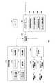
図1は、本実施形態に係るデバイスプロビジョニング環境10を示す。本実施形態において、デバイスプロビジョニング環境10は、ネットワークデバイス100に対して出荷前の設定をするプロビジョニングシステム120と、ネットワークデバイス100に対して設置時の設定をするプロビジョニングシステム140とを備え、クラウドコンピュータまたはフォグコンピュータ等(以下「クラウドコンピュータ等」と示す。)である基盤システム160にネットワークデバイス100を簡単かつセキュアに接続可能とする。 FIG. 1 shows a
デバイスプロビジョニング環境10は、ネットワークデバイス100に対して出荷前の設定・準備をするためのプロビジョニングシステム120、ネットワーク125、端末130、およびプリンタ135と、ユーザへと届けられたネットワークデバイス100に対して設置時の設定をするためのプロビジョニングシステム140および端末150と、1または複数のネットワークデバイス100の監視・制御等を行うクラウドコンピューティングシステムまたはフォグコンピューティングシステム(以下「クラウドコンピューティングシステム等」と示す。)を構築するための基盤システム160および端末165とを備える。 The
ネットワークデバイス100は、インターネット、ワイドエリアネットワーク、ローカルエリアネットワーク及び携帯回線網等のいずれかのネットワーク145に接続可能なフィールド機器若しくはセンサ等、または、このような機器とネットワーク145との間に設けられるゲートウェイ若しくはハブ等である。ネットワークデバイス100は、ネットワーク145に接続可能なインターフェイスモジュールと、当該インターフェイスモジュールに交換可能に接続されるアプリケーションモジュールとを含んで構成されてもよい。アプリケーションモジュールは、例えばセンサモジュール、アクチュエータモジュール、入出力を行う中継モジュールなどでよい。ネットワークデバイス100は、プロビジョニングシステム120により提供される、納入対象ネットワークデバイス100に固有のデバイス識別情報を含むコードを印刷したコードラベル102と、デバイス識別情報を記憶するための識別情報記憶領域104と、プロビジョニングシステム120により提供される、納入先でネットワーク145に接続された納入対象ネットワークデバイス100を認証するためのデバイス認証情報を記憶するための認証情報記憶領域106と、納入対象ネットワークデバイス100が基盤システム160に接続するための暗号鍵を記憶するための暗号鍵記憶領域108とを備える。 The
プロビジョニングシステム120は、納入先でネットワーク125に接続される納入対象ネットワークデバイス100の納入前に、納入対象ネットワークデバイス100を予め設定しておくことにより、納入対象ネットワークデバイス100を簡単かつセキュアに基盤システム160に接続可能とするプロビジョニングサービスを提供するためのコンピュータシステムである。プロビジョニングシステム120は、このプロビジョニングサービスを提供するサービス業者によって運用される。プロビジョニングシステム120は、クラウドコンピューティングシステム等であってよく、1または複数のサーバコンピュータ等によって実現されてよい。本実施形態において、このサービス業者は、ネットワークデバイス100の製造者または販売者等のプロバイダ(またはベンダ)とは別である。これに代えて、このサービス業者は、ネットワークデバイス100のプロバイダと同一であってもよい。また、このサービス業者は、基盤システム160によるサービスを提供するサービス業者と同一であってもよく、異なっていてもよい。なお、本実施形態に係る基盤システム160は、複数のプロバイダが各々製造・販売するネットワークデバイス100についてプロビジョニングサービスを提供するべく、各々のプロバイダに対して固有のアカウントを設ける。 The
プロビジョニングシステム120は、納入先でネットワーク145に接続される納入対象のネットワークデバイス100のプロバイダの端末130からの要求に応じて、納入対象ネットワークデバイス100の納入前に、基盤システム160が納入対象ネットワークデバイス100を識別可能な固有のデバイス識別情報、納入先でネットワークに接続された納入対象ネットワークデバイス100を認証するためのデバイス認証情報、およびその他の必要な情報を納入対象ネットワークデバイス100に設定するサービスを提供する。 In the
ネットワーク125は、プロビジョニングシステム120および端末130の間を有線または無線により接続する。ネットワーク125は、インターネット、ワイドエリアネットワーク、またはローカルエリアネットワーク等であってよく、携帯回線網を含んでもよい。 The
端末130は、納入対象ネットワークデバイス100のプロバイダが使用する端末であり、納入対象ネットワークデバイス100の設定装置として機能する。端末130は、PC(パーソナルコンピュータ)、タブレット型コンピュータ、スマートフォン、ワークステーション、サーバコンピュータ、または汎用コンピュータ等のコンピュータであってよく、複数のコンピュータが接続されたコンピュータシステムであってもよい。端末130は、プロビジョニングシステム120が提供するプロビジョニングサービスを利用するために用いられ、プロビジョニングシステム120により提供されるデバイス識別情報およびデバイス認証情報を納入対象ネットワークデバイス100の識別情報記憶領域104および認証情報記憶領域106に設定する。 The terminal 130 is a terminal used by the provider of the delivery
プリンタ135は、有線または無線により端末130に接続され、端末130からの指示に応じてデバイス識別情報を含むコードを例えばシール等に印刷する。本実施形態において、印刷されたコードを含むコードラベル102は、納入対象ネットワークデバイス100に貼付される。 The
プロビジョニングシステム140は、ネットワークデバイス100を簡単かつセキュアに基盤システム160に接続するプロビジョニングサービスを提供するサービス業者が有するコンピュータシステムである。プロビジョニングシステム140は、クラウドコンピューティングシステム等であってよく、1または複数のサーバコンピュータ等によって実現されてよい。本実施形態において、プロビジョニングシステム120によるサービスを提供するサービス業者(出荷プロビジョニングサービスのサービス業者)と、プロビジョニングシステム140によるサービスを提供するサービス業者(設置プロビジョニングサービスのサービス業者)とは、同一であり、ネットワークデバイス100のプロバイダとは異なる。これに代えて、これらのサービス業者とネットワークデバイス100のプロバイダとは同一であってよく、出荷プロビジョニングサービスのサービス業者と設置プロビジョニングサービスのサービス業者とが異なってもよい。なお、本実施形態に係るプロビジョニングシステム140は、各々ネットワークデバイス100を購入して使用する複数のテナント(企業、企業内の部署、その他のグループ)のそれぞれに対して、固有のアカウントを設ける。 The
プロビジョニングシステム140は、納入対象ネットワークデバイス100を納入先で設定する設定者のアクティベーション要求を端末150から受けて、納入先でネットワーク145に接続された納入対象ネットワークデバイス100を、デバイス認証情報を用いて認証する。そして、プロビジョニングシステム140は、正しく認証できたことを条件として、基盤システム160が提供するサービスにネットワークデバイス100を登録し、基盤システム160に接続するための暗号鍵を納入対象ネットワークデバイス100に提供する。プロビジョニングシステム140が提供した暗号鍵は、ネットワークデバイス100内の暗号鍵記憶領域108に格納される。 The
ネットワーク145は、ネットワークデバイス100、プロビジョニングシステム140、端末150、基盤システム160、および端末165の間を無線または有線により接続する。ネットワーク145は、インターネット、ワイドエリアネットワーク、またはローカルエリアネットワーク等であってよく、携帯回線網を含んでもよい。本図においてネットワーク125およびネットワーク145は、別のネットワークとしているが、これに代えて、ネットワーク125およびネットワーク145は同一のネットワークであってよい。 The
端末150は、納入対象ネットワークデバイス100の納入先で納入対象ネットワークデバイス100を設定する設定者が使用する端末である。この設定者は、一例としてネットワークデバイス100を使用するテナントまたは設置業者等の構成員である。本実施形態において端末150は一例としてスマートフォン、タブレット型コンピュータ、またはPC等である。端末150は、プロビジョニングシステム140が提供するプロビジョニングサービスを利用するために用いられ、納入対象ネットワークデバイス100のコードラベル102からデバイス識別情報等を取得して、納入対象ネットワークデバイス100のアクティベーションをプロビジョニングシステム140に要求する。 The terminal 150 is a terminal used by a setter who sets the delivery
基盤システム160(ファンデーションシステム160)は、納入対象ネットワークデバイス100を含む複数のネットワークデバイス100を接続したネットワークシステムを管理する。本実施形態では一例として、基盤システム160は、ネットワークシステムの構築サービスを提供するサービス提供システムとして機能するコンピューティングシステムである。基盤システム160は、クラウドコンピューティングシステム等であってよく、1または複数のサーバコンピュータ等によって実現されてよい。基盤システム160を用いて構築されるネットワークシステムは、例えばIoTまたはIIoTシステム等のデバイスネットワークである。基盤システム160は、ネットワークシステムにおいて複数のネットワークデバイス100を制御するクラウドコンピュータ等として機能する。基盤システム160は、センサ等を搭載した1または複数のネットワークデバイス100からセンスデータを取得して、端末165を介してユーザまたは監視者等に情報を提示するインターフェイスを提供し、これに加えて、または、これに代えて、センスデータに応じて制御演算を行って、アクチュエータ等を搭載したネットワークデバイス100を制御する等の情報処理を行う。なお、本実施形態に係る基盤システム160は、各々ネットワークデバイス100を購入して使用する複数のテナント(のそれぞれ)に対して、固有のアカウントを設ける。 The infrastructure system 160 (foundation system 160) manages a network system in which a plurality of
端末165は、複数のネットワークデバイス100を接続したネットワークシステムのユーザが使用する端末である。端末165は、PC(パーソナルコンピュータ)、タブレット型コンピュータ、スマートフォン、ワークステーション、サーバコンピュータ、または汎用コンピュータ等のコンピュータであってよく、複数のコンピュータが接続されたコンピュータシステムであってもよい。端末165は、ネットワーク145を介して基盤システム160に接続され、基盤システム160が提供するネットワークシステム構築サービスを利用するために用いられる。 The terminal 165 is a terminal used by a user of a network system to which a plurality of
以上に示したデバイスプロビジョニング環境10によれば、プロビジョニングシステム120が提供するプロビジョニングサービスを利用して、出荷前に納入対象ネットワークデバイス100を基盤システム160に接続するためのデバイス識別情報等の設定を行い、プロビジョニングシステム140が提供するプロビジョニングサービスを利用して、設定者が端末150によって簡単に納入対象ネットワークデバイス100を設定できるようにする。これにより、デバイスプロビジョニング環境10は、ネットワークデバイス100のプラグ・アンド・プレイまたはこれに近い利便性を提供することができる。また、出荷前にプロビジョニングシステム120がデバイス認証情報をネットワークデバイス100に格納し、納入後にプロビジョニングシステム140がデバイス認証情報を用いてネットワークデバイス100を認証することにより、納入対象ネットワークデバイス100とは異なるネットワークデバイスが不正に基盤システム160に接続されてネットワークシステムのセキュリティが脅かされるのを防止することができる。 According to the
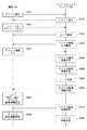
図2は、本実施形態に係るネットワークデバイス100の一例であるセンサ装置200を示す。センサ装置200は、コードラベル102と、設定記憶部210と、センサ220と、センスデータ取得部230と、センスデータ記憶部240と、アクセス制御部250と、ネットワークインターフェイス260とを備える。コードラベル102は、ネットワークデバイス100の本体または付属品上に貼付された、デバイス識別情報等をコーディングしたコードを示すラベルであり、センサ装置200のデバイス識別情報を端末150が取得可能に提供するデバイス識別情報提供部として機能する。このコードは、バーコードまたは2次元コード(QRコード(登録商標))等であってよく、文字列等の端末150によって画像から読み取り可能な任意のコードであってもよい。これに代えて、センサ装置200は、端末150が近距離無線通信等により取得可能な形態、すなわち例えば非接触ICカード等の形態でデバイス識別情報等を保持してもよい。 FIG. 2 shows a
設定記憶部210は、センサ装置200内の設定情報を記憶する。センサ装置200は、識別情報記憶領域104と、パスコード記憶領域212と、宛先情報記憶領域214と、認証情報記憶領域106と、暗号鍵記憶領域108と、宛先情報記憶領域216とを有する。識別情報記憶領域104は、プロビジョニングシステム120によって決定されるセンサ装置200のデバイス識別情報をセンサ装置200の納入前に格納するための領域であり、デバイス識別情報記憶部として機能する。 The setting
パスコード記憶領域212は、端末150がプロビジョニングシステム140に対してセンサ装置200のアクティベーション処理を要求するときに用いるパスコードをセンサ装置200の納入前に格納するための領域であり、パスコード記憶部として機能する。なお、本実施形態に係るセンサ装置200等のネットワークデバイス100は、デバイス識別情報に加えてパスコードを用いてアクティベーションされるが、これに代えて、センサ装置200等は、パスコード記憶領域212を有さずパスコードを用いずにアクティベーションされるようにしてもよい。宛先情報記憶領域214は、プロビジョニングシステム140の宛先情報、すなわち例えばプロビジョニングシステム140のURL等をセンサ装置200の納入前に格納するための領域であり、プロビジョニングシステム140用の宛先情報記憶部として機能する。 The
認証情報記憶領域106は、プロビジョニングシステム140によりセンサ装置200を認証させるために用いるデバイス認証情報をセンサ装置200の納入前に格納するための領域であり、デバイス認証情報記憶部として機能する。暗号鍵記憶領域108は、センサ装置200を基盤システム160に接続するための暗号鍵を格納するための領域であり、暗号鍵記憶部として機能する。宛先情報記憶領域216は、基盤システム160の宛先情報を格納するための領域であり、基盤システム160用の宛先情報記憶部として機能する。設定記憶部210の記憶領域のうち、少なくとも認証情報記憶領域106および暗号鍵記憶領域108は、不正読出ができないセキュアな記憶領域であってよい。 The authentication
センサ220は、例えば温度センサ、湿度センサ、流速センサ、圧力センサ、電圧センサ、電流センサ等の物理量を測定するセンサである。センサ装置200は、2以上のセンサ220を備えてもよい。 The
センスデータ取得部230は、センサ220からの信号をセンスデータに変換する。例えば、センスデータ取得部230は、センサ220から入力されるアナログ信号をデジタル信号に変換してセンスデータを得る。センスデータ記憶部240は、センスデータを記憶する。センスデータ記憶部240に記憶されるセンスデータには、当該センスデータの測定された時刻が含まれてよく、この場合、センサ装置200には計時を行う計時部(図示せず)が具備されてよい。アクセス制御部250は、ネットワークインターフェイス260からの要求に応じて設定記憶部210およびセンスデータ記憶部240内のデータをアクセスし、ネットワークインターフェイス260へと提供する。また、アクセス制御部250は、ネットワークインターフェイス260からの要求に応じて、設定記憶部210に各種の設定データを書き込む。 The sense
ネットワークインターフェイス260は、ネットワーク125およびネットワーク145等のネットワークに接続され、ネットワークを介して受信する要求等に応じて設定記憶部210またはセンスデータ記憶部240をアクセスすることをアクセス制御部250に指示する。ネットワークインターフェイス260は、イーサネット(登録商標)等の通信回線、3G回線、4G回線、若しくはLTE回線等の携帯回線、またはLoRa等のIoT向け通信回線等に接続可能であってよい。 The
ネットワークインターフェイス260は、設定格納処理部262と、デバイス認証処理部264と、暗号鍵受信部266と、サービス接続処理部268とを有する。設定格納処理部262は、センサ装置200の納入前にセンサ装置200が端末130に接続された状態において、端末130からデバイス識別情報、パスコード、プロビジョニングシステム140の宛先情報、およびデバイス認証情報等の出荷前にセンサ装置200に設定すべき情報を受信して識別情報記憶領域104、パスコード記憶領域212、宛先情報記憶領域214、および認証情報記憶領域106等に格納する。デバイス認証処理部264は、センサ装置200がネットワーク145に接続されたことに応じて、認証情報記憶領域106に記憶されたデバイス認証情報を用いて、センサ装置200をプロビジョニングシステム140により認証させる。暗号鍵受信部266は、センサ装置200を認証したプロビジョニングシステム140から、基盤システム160が提供するネットワークシステム構築サービスにアクセスするための暗号鍵を受信して、暗号鍵記憶領域108に格納する。サービス接続処理部268は、暗号鍵記憶領域108に格納された暗号鍵を用いて、ネットワークシステム構築サービスを提供する基盤システム160に接続する。 The
以上に示したセンサ装置200によれば、センサ装置200の出荷前にプロビジョニングシステム120から提供されるデバイス認証情報をセンサ装置200内の認証情報記憶領域106に格納し、格納したデバイス認証情報を用いてセンサ装置200の設置時にセンサ装置200を基盤システム160に認証させることができる。したがって、センサ装置200は、ユーザが発注してプロバイダにより設定された正規品である場合に限ってプロビジョニングシステム140および基盤システム160に接続可能となり、センサ装置200に付されたデバイス識別情報を盗んで別のネットワークデバイスに設定する等した不正品はプロビジョニングシステム140および基盤システム160に接続できなくなる。 According to the
図3は、本実施形態に係るネットワークデバイス100の一例であるセンサゲートウェイ装置300を示す。センサゲートウェイ装置300は、コードラベル102と、設定記憶部210と、有線センサ接続部320と、無線センサ接続部330と、センスデータ記憶部340と、アクセス制御部250と、ネットワークインターフェイス260とを備える。本図に示した各部材のうち、図2と同じ符号を付した部材は図2と同様の機能・構成をとるので、以下相違点を除き説明を省略する。 FIG. 3 shows a
有線センサ接続部320は、ローカルエリアネットワーク、およびUSB等を用いる有線接続により1または複数のセンサ装置に接続され、センサ装置との間で通信を行う。無線センサ接続部330は、LoRa、携帯回線、無線LAN、またはBluetooth(登録商標)等の無線接続によりセンサ装置等と接続され、1または複数のセンサ装置との間で通信を行う。 The wired
センスデータ記憶部340は、有線センサ接続部320および無線センサ接続部330に接続される1または複数のセンサからのセンスデータを記憶する。アクセス制御部250は、ネットワークインターフェイス260からの要求に応じて設定記憶部210およびセンスデータ記憶部340内のデータをアクセスし、ネットワークインターフェイス260へと提供する。また、アクセス制御部250は、ネットワークインターフェイス260からの要求に応じて、設定記憶部210に各種の設定データを書き込む。 The sense
なお、ネットワークデバイス100は、アクチュエータ等の制御対象を有するフィールド機器を接続可能であってもよい。このようなネットワークデバイス100は、ネットワークインターフェイス260が制御対象を制御するための制御データを受信し、アクセス制御部250が制御データをメモリ等の制御データ記憶部に格納し、有線センサ接続部320または無線センサ接続部330が制御データをフィールド機器へと送信する構成をとりうる。 The
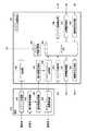
図4は、本実施形態に係るプロビジョニングシステム120および端末130の構成を示す。プロビジョニングシステム120は、設定者ログイン処理部410と、識別情報決定部415と、デバイスDB420と、認証情報生成部425と、コード生成部430と、識別情報送信部435と、認証情報送信部440と、デバイス登録送信部445とを備える。 FIG. 4 shows the configuration of the
設定者ログイン処理部410は、納入対象ネットワークデバイス100の納入前に、納入対象ネットワークデバイス100を設定する設定者のログインを端末130から受け付ける。この設定者は、納入対象ネットワークデバイス100のプロバイダの社員等の納入対象ネットワークデバイス100を設定する者であってよく、設定者ログイン処理部410は、そのプロバイダのアカウントに対するログインを端末130から受け付ける。 The setter
識別情報決定部415は、納入対象ネットワークデバイス100の納入前に、設定者の指示に応じて端末130が取得した、納入対象ネットワークデバイス100に関するデバイス情報を受信して、デバイス識別情報を決定する。識別情報決定部415は、納入対象ネットワークデバイス100のデバイス情報にデバイス識別情報を追加してデバイスDB420に書き込むことにより、納入対象ネットワークデバイス100をデバイスDB420に登録する。ここで識別情報決定部415は、納入対象ネットワークデバイス100に設定するパスコードを乱数等により決定し、デバイス情報に追加してデバイスDB420に書き込む。 The identification
デバイスDB420は、プロビジョニングサービスの対象となる複数のネットワークデバイス100に関するデバイス情報を記憶する。デバイスDB420が記憶するデバイス情報は、デバイス識別情報および認証情報生成部425により設定されるデバイス認証情報を含む。デバイス情報は、プロバイダ識別情報、シリアル番号、機種名等の機種識別情報、およびテナント識別情報等の端末130から受信するデバイス情報に含まれる各情報を任意で含んでもよく、納入対象ネットワークデバイス100に設定されるべきパスコード、プロビジョニングシステム140の宛先情報、および基盤システム160の宛先情報を含んでもよい。また、デバイス情報は、プロビジョニングシステム140に対する納入対象ネットワークデバイス100のPKI(Public−Key Infrastructure)認証、および納入対象ネットワークデバイス100と他の機器との間の暗号化通信に用いる納入対象ネットワークデバイス100の公開鍵等を含んでもよい。 The
認証情報生成部425は、納入対象ネットワークデバイス100のデバイス情報がデバイスDB420に登録されたことに応じて、納入先で納入対象ネットワークデバイス100を認証するためのデバイス認証情報を生成する。認証情報生成部425は、生成したデバイス認証情報をデバイスDB420に書き込んで、納入対象ネットワークデバイス100のデバイス情報に追加する。 The authentication information generation unit 425 generates device authentication information for authenticating the delivery
コード生成部430は、デバイス識別情報をコーディングした、納入対象ネットワークデバイス100の本体または付属品上に貼付、印刷、および刻印の少なくとも1つで設けられるべきコードを生成する。本実施形態において、コード生成部430は、デバイス識別情報に加えて、パスコードおよびプロビジョニングシステム140の宛先情報を更にコーディングしたコードを生成する。 The code generation unit 430 generates a code to be provided by at least one of sticking, printing, and engraving on the main body or accessory of the delivery
識別情報送信部435は、デバイス識別情報を納入対象端末130へと送信して、納入先で納入対象ネットワークデバイス100の本体または付属品からデバイス識別情報を取得可能に設定させる。本実施形態においては、識別情報送信部435は、コード生成部430が生成したコードを端末130へと送信して端末130によりプリンタ135へと印刷させて、設定者により納入対象ネットワークデバイス100の本体または付属品に貼付させる。なお、コードは納入対象ネットワークデバイス100の本体または付属品に対し、貼付、印刷、および刻印の少なくとも一つで設けられればよく、一例として、一部が印刷により設けられ、残りの部分が刻印により設けられてもよい。また、識別情報送信部435は、納入対象ネットワークデバイス100のデバイス識別情報、パスコード、およびプロビジョニングシステム140の宛先情報を端末130へと送信し、納入対象ネットワークデバイス100内の識別情報記憶領域104、パスコード記憶領域212、および宛先情報記憶領域214へと書き込ませる。 The identification
認証情報送信部440は、デバイス認証情報を端末130へと送信して、納入対象ネットワークデバイス100の認証情報記憶領域106に記憶させる。また、認証情報送信部440は、基盤システム160の宛先情報を端末130へと送信して、納入対象ネットワークデバイス100の宛先情報記憶領域216に記憶させる。 The authentication
デバイス登録送信部445は、デバイスDB420に登録されたデバイス情報をプロビジョニングシステム140へと送信する。 The device
端末130は、ログイン処理部450と、デバイス情報取得部455と、デバイス情報送信部460と、識別情報受信部465と、識別情報設定部470と、認証情報受信部475と、認証情報設定部480とを備える。これらの機能は、端末130がプロビジョニングシステム120のプロビジョニングサービスに関するWebページの処理を行うことによって実現されてよい。 The terminal 130 includes a
ログイン処理部450は、端末130を操作する設定者の指示に応じて、プロビジョニングシステム120へのログイン処理を行う。デバイス情報取得部455は、設定者のログイン中に、納入対象ネットワークデバイス100のデバイス情報を取得する。デバイス情報送信部460は、取得されたデバイス情報をプロビジョニングシステム120内の識別情報決定部415へと送信する。 The
識別情報受信部465は、プロビジョニングシステム120の識別情報送信部435からデバイス識別情報を受信する。本実施形態に係る識別情報受信部465は、プロビジョニングシステム120内のコード生成部430が生成したコードと、デバイス識別情報、パスコード、およびプロビジョニングシステム140の識別情報とを受信する。 The identification
識別情報設定部470は、納入先で納入対象ネットワークデバイス100の本体または付属品からデバイス識別情報を取得可能となるように、納入対象ネットワークデバイス100にデバイス識別情報を設定する。本実施形態において、識別情報設定部470は、識別情報受信部465が受信したコードを、プリンタ135によりラベル上に印刷させ、設定者によりコードラベル102を納入対象ネットワークデバイス100の本体に貼付させる。また、識別情報設定部470は、デバイス識別情報、パスコード、およびプロビジョニングシステム140の識別情報をプロビジョニングシステム120から受信して、納入対象ネットワークデバイス100内の識別情報記憶領域104、パスコード記憶領域212、および宛先情報記憶領域214に書き込む。 The identification
認証情報受信部475は、プロビジョニングシステム120からデバイス認証情報を受信する。認証情報設定部480は、受信したデバイス認証情報を、納入対象ネットワークデバイス100の認証情報記憶領域106に記憶させる。 The authentication
図5は、本実施形態に係るプロビジョニングシステム120および端末130の処理フローを示す。S510(ステップS510)において、端末130内のログイン処理部450は、設定者の指示に応じて、プロビジョニングシステム120へのアクセスを発行する。S515において、プロビジョニングシステム120内の設定者ログイン処理部410は、プロビジョニングシステム120からのアクセスに応じてログイン画面を端末130へと送信し、ログインを要求する。 FIG. 5 shows a processing flow of the
S520において、端末130内のログイン処理部450は、設定者からログインIDおよびパスワードの入力を受けて、ログインIDおよびパスワードをプロビジョニングシステム120へと送信する。S525において、プロビジョニングシステム120内の設定者ログイン処理部410は、ログインIDおよびパスワードに基づくユーザ認証を行い、正しく認証されたことに応じてそのログインIDに対応するアカウントへのログインを行わせる。以後、S530からS580までの処理は、設定者のログイン中に行われる。 In S520, the
S530において、プロビジョニングシステム120は、納入対象ネットワークデバイス100のデバイス情報を入力するための画面を端末130へと送信して、デバイス情報の入力を要求する。これを受けて、端末130内のデバイス情報取得部455は、S535において、デバイス情報を入力するための画面に対する入力を受け付けて、納入対象ネットワークデバイス100のデバイス情報を取得する。デバイス情報取得部455は、納入対象ネットワークデバイス100との間で通信を行って納入対象ネットワークデバイス100からデバイス情報を取得してもよい。デバイス情報送信部460は、取得されたデバイス情報をプロビジョニングシステム120へと送信する。 In S530, the
S540において、プロビジョニングシステム120内の識別情報決定部415は、デバイス情報を受信して、デバイス識別情報を決定する。また、識別情報決定部415は、納入対象ネットワークデバイス100のパスコードを更に決定してもよい。識別情報決定部415は、決定したデバイス識別情報等をデバイス情報送信部460から受信したデバイス情報に追加して、デバイスDB420に登録する。ネットワーク上でユニークに納入対象ネットワークデバイス100を識別可能とするために、識別情報決定部415は、納入対象ネットワークデバイス100のプロバイダに固有のプロバイダ識別情報および納入対象ネットワークデバイス100のシリアル番号等のデバイス情報に含まれる情報、および必要に応じてその他の納入対象ネットワークデバイス100を特定するのに十分な情報を組み合わせる等により、デバイス識別情報を決定してよい。 In S540, the identification
S545において、プロビジョニングシステム120内の認証情報生成部425は、納入対象ネットワークデバイス100のデバイス認証情報を生成して、デバイスDB420内のデバイス情報に追加する。一例として、認証情報生成部425は、デバイス認証情報として、納入対象ネットワークデバイス100のデバイス情報の少なくとも一部に対してプロビジョニングシステム120が電子署名をしたデジタル証明書を生成してもよい。一例として、認証情報生成部425は、納入対象ネットワークデバイス100をPKI認証によりプロビジョニングシステム140に認証させるためのデジタル証明書を生成してよい。S550において、コード生成部430は、デバイス識別情報、パスコード、およびプロビジョニングシステム140の宛先情報を含む情報をコーディングしたコードを生成する。 In S545, the authentication information generation unit 425 in the
S555において、プロビジョニングシステム120内の識別情報送信部435は、デバイス識別情報を端末130へと送信する。ここで、識別情報送信部435は、S550において生成されたコードと、納入対象ネットワークデバイス100のデバイス識別情報、パスコード、およびプロビジョニングシステム140の宛先情報とを、端末130へ送信する。 In S555, the identification
S560において、端末130内の識別情報受信部465は、S555において送信されたデバイス識別情報等を受信する。識別情報設定部470は、S550において生成されたコードをプリンタ135を用いて印刷し、設定者によりネットワークデバイス100の本体等に貼付させる。また、識別情報設定部470は、納入対象ネットワークデバイス100のデバイス識別情報、パスコード、およびプロビジョニングシステム140の宛先情報を、納入対象ネットワークデバイス100に設定する。 In S560, the identification
S570において、プロビジョニングシステム120内の認証情報送信部440は、納入対象ネットワークデバイス100のデバイス認証情報を送信する。ここで、認証情報送信部440は、デバイス認証情報を含むファイルを端末130へと送信してもよい。S580において、認証情報受信部475はデバイス認証情報を受信し、認証情報設定部480はデバイス認証情報を納入対象ネットワークデバイス100に設定する。S585において、デバイス登録送信部445は、デバイスDB420に登録されたネットワークデバイス100のデバイス情報をプロビジョニングシステム140へと送信する。 In S570, the authentication
以上に示したプロビジョニングシステム120および端末130によれば、端末130からプロビジョニングサービスへのログインおよびインタラクティブな作業を通じて、納入先で納入対象ネットワークデバイス100の本体または付属品から取得可能なデバイス識別情報と、納入先でネットワークに接続された納入対象ネットワークデバイス100を認証するためのデバイス認証情報とを設定することができる。これにより、納入対象ネットワークデバイス100は、納入後の設定処理において、簡単かつセキュアにプロビジョニングシステム140に接続することができる。 According to the
以上においては、プロビジョニングシステム120および端末130は、ログインおよびその後のインタラクティブな処理を通じて納入対象ネットワークデバイス100を設定する。これに代えて、端末130は、インタラクティブな処理無しに自動的にプロバイダ情報およびデバイス情報をプロビジョニングシステム120へと送信し、プロビジョニングシステム120から受信されるコードを印刷し、プロビジョニングシステム120から受信される納入対象ネットワークデバイス100のデバイス識別情報、パスコード、およびプロビジョニングシステム140の宛先情報を納入対象ネットワークデバイス100へと書き込んでもよい。 In the above, the
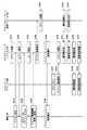
図6は、本実施形態に係るプロビジョニングシステム140および端末150の構成を示す。プロビジョニングシステム140は、デバイス登録受信部610と、デバイスDB615と、デバイス認証部620と、テナントログイン処理部625と、識別情報受信部630と、アクティベーション処理部635と、デバイス登録要求部640と、暗号鍵取得部645と、基盤宛先取得部650と、暗号鍵送信部655と、基盤宛先送信部660とを備える。 FIG. 6 shows the configuration of the
デバイス登録受信部610は、プロビジョニングシステム120内のデバイス登録送信部445によって送信されたデバイス情報を受信して、デバイスDB615に登録する。デバイスDB615は、プロビジョニングサービスの対象となる複数のネットワークデバイス100に関するデバイス情報を記憶する。デバイスDB615が記憶するデバイス情報は、デバイスDB420が記憶するデバイス情報に加え、納入対象ネットワークデバイス100が基盤システム160に接続するための暗号鍵、および納入対象ネットワークデバイス100が接続すべき基盤システム160の宛先情報を含んでよい。ネットワークデバイス100がセンサ装置200である場合には、デバイスDB615に記憶されるデバイス情報は、センサ装置200が出力するセンスデータを識別するためのセンスデータ識別情報をさらに含んでよい。センスデータ識別情報は、センサ装置200の設置位置および測定物理量に固有の識別情報でよく、例えば測定物理量と、その識別番号との組み合わせで示されてよい。一例としてセンスデータが第1の処理工程を行う設備内の2番目のベルトコンベアの温度に関するものである場合には、センスデータ識別情報は「Temp1」のように示されてよい。これに代えて、センスデータ識別情報は、設置位置および測定物理量との組み合わせで階層的に示されてもよく、一例として「製造工程(1)−ベルトコンベア(2)−温度」のように示されてもよい。 The device
デバイス認証部620は、納入先でネットワーク125に接続された納入対象ネットワークデバイス100を、納入対象ネットワークデバイス100に記憶されたデバイス認証情報を用いて認証する。デバイス認証部620は、納入対象ネットワークデバイス100が正しく認証されたことに応じて、納入対象ネットワークデバイス100が認証済みであることを示す認証済情報をデバイスDB615内のデバイス情報に追加する。 The
テナントログイン処理部625は、納入対象ネットワークデバイス100の納入先で、納入先のテナントのユーザである設置者によって使用される端末150から、テナントのログインを受け付ける。識別情報受信部630は、納入先で使用される端末150が納入対象ネットワークデバイス100の本体または付属品から取得したデバイス識別情報およびパスコードを受信する。アクティベーション処理部635は、納入対象ネットワークデバイス100のデバイス識別情報が受信されたことに応じて、受信されたデバイス識別情報が割り当てられた納入対象ネットワークデバイス100をアクティベーションする処理を行う。 The tenant
デバイス登録要求部640は、アクティベーション処理中である納入対象ネットワークデバイス100のデバイス情報を基盤システム160へと送信し、基盤システム160が提供するネットワークシステム構築サービスに納入対象ネットワークデバイス100を登録することを基盤システム160に要求する。暗号鍵取得部645は、ネットワークシステム構築サービスに接続するために納入対象ネットワークデバイス100が使用すべき暗号鍵を基盤システム160から取得して、デバイスDB615内における納入対象ネットワークデバイス100のデバイス情報に追加する。基盤宛先取得部650は、納入対象ネットワークデバイス100が基盤システム160に接続するために用いる基盤システム160の宛先情報を基盤システム160から取得して、デバイスDB615内における納入対象ネットワークデバイス100のデバイス情報に追加する。 The device
暗号鍵送信部655は、納入対象ネットワークデバイス100が正しく認証されたことに応じて、暗号鍵取得部645が取得した暗号鍵を、納入対象ネットワークデバイス100に対して送信し、暗号鍵記憶領域108へと記憶させる。基盤宛先送信部660は、納入対象ネットワークデバイス100が正しく認証されたことに応じて、基盤宛先取得部650が取得した宛先情報を、納入対象ネットワークデバイス100に対して送信し、宛先情報記憶領域216へと記憶させる。 The encryption
端末150は、ログイン処理部670と、識別情報取得部675と、識別情報送信部680と、アクティベーション結果通知部685とを備える。ログイン処理部670は、納入対象ネットワークデバイス100の納入後に納入対象ネットワークデバイス100を設置する設置者の指示に応じて、プロビジョニングシステム140へのログイン処理を行う。 The terminal 150 includes a
識別情報取得部675は、テナントの設置者のログイン中に、納入対象ネットワークデバイス100の本体または付属品から、納入対象ネットワークデバイス100のデバイス識別情報を取得する。本実施形態において、識別情報取得部675は、設置者の操作を受けて、納入対象ネットワークデバイス100の本体に貼付されたコードラベル102を撮像し、撮像画像に含まれるコードを認識してコーディングされたデバイス識別情報、パスコード、およびプロビジョニングシステム140の宛先情報を復元する。 The identification
識別情報送信部680は、識別情報取得部675が取得したデバイス識別情報およびパスコードを、識別情報取得部675が取得した宛先情報によって指定されるプロビジョニングシステム140へと送信して、納入対象ネットワークデバイス100のアクティベーションを要求する。アクティベーション結果通知部685は、納入対象ネットワークデバイス100のアクティベーション結果をプロビジョニングシステム140から受信して、端末150を使用する設置者に通知する。 The identification
なお、本実施形態においては、プロビジョニングシステム120およびプロビジョニングシステム140が異なるコンピュータシステムである場合を例として示したが、プロビジョニングシステム120およびプロビジョニングシステム140は同一のコンピュータシステムで実現され、出荷プロビジョニングサービスおよび設置プロビジョニングサービスが同一のサービス業者によって提供されてもよい。このような構成においては、基本的には、図4のプロビジョニングシステム120および図6のプロビジョニングシステム140の各構成要素がプロビジョニングシステムに含まれてよい。この場合、プロビジョニングシステム120内のデバイスDB420とプロビジョニングシステム140内のデバイスDB615とが共通化されてよく、デバイス登録送信部445およびデバイス登録受信部610は設けられなくてもよい。 In the present embodiment, the case where the
図7は、本実施形態に係る端末150、ネットワークデバイス100、プロビジョニングシステム140、および基盤システム160の処理フローを示す。S705において、プロビジョニングシステム140内のデバイス登録受信部610は、プロビジョニングシステム120内のデバイス登録送信部445からデバイス情報を受信して、デバイスDB615に登録する。 FIG. 7 shows the processing flow of the terminal 150, the
S715において、プロビジョニングシステム140のテナントログイン処理部625は、テナントのユーザである設置者の指示に応じて、プロビジョニングシステム140へのアクセスを発行する。S720において、端末150内のログイン処理部670は、端末150からのアクセスに応じてログイン画面を端末150へと送信し、ログインを要求する。 In S715, the tenant
S725において、端末150は、設置者からログインIDおよびパスワードの入力を受けて、ログインIDおよびパスワードをプロビジョニングシステム140へと送信する。S730において、基盤システム160内のテナントログイン処理部625は、ログインIDおよびパスワードに基づくユーザ認証を行い、正しく認証されたことに応じてそのログインIDに対応するテナントのアカウントへのログインを行わせる。以後、S735からS775までの処理は、テナントの設置者のログイン中に行われる。 In S725, the terminal 150 receives the login ID and password input from the installer and transmits the login ID and password to the
S735において、端末150内の識別情報取得部675は、納入対象ネットワークデバイス100のデバイス識別情報を取得する。本実施形態において、識別情報取得部675は、コードラベル102を撮像し、撮像画像に含まれるコードを認識してコーディングされたデバイス識別情報、パスコード、およびプロビジョニングシステム140の宛先情報を復元する。端末150内の識別情報送信部680は、識別情報取得部675が取得したデバイス識別情報およびパスコードを、識別情報取得部675が取得した宛先情報によって指定されるプロビジョニングシステム140へと送信して、納入対象ネットワークデバイス100のアクティベーションを要求する。なお、納入対象ネットワークデバイス100がセンサ装置200である場合には、識別情報取得部675はセンサ装置200の設置者の操作に基づいてセンサ装置200の設置位置および測定物理量を取得してセンスデータ識別情報を生成してよく、識別情報送信部680は当該センスデータ識別情報もプロビジョニングシステム140に送信してよい。 In S735, the identification
S740において、プロビジョニングシステム140内の識別情報受信部630は、端末150から送信されたデバイス識別情報等を含むアクティベーション要求を受信する。プロビジョニングシステム140内のアクティベーション処理部635は、受信されたデバイス識別情報が割り当てられた納入対象ネットワークデバイス100をテナントのネットワークデバイス100としてアクティベーションする処理を行う。本実施形態に係るアクティベーション処理部635は、当該デバイス識別情報に対応するデバイスDB615内のデバイス情報に、納入対象ネットワークデバイス100がアクティベーション処理中であることを示すステータス情報を追加して、プロビジョニングシステム140内でアクティベーション処理が進むようにする。納入対象ネットワークデバイス100がセンサ装置200である場合には、アクティベーション処理部635は、当該センサ装置200が出力するセンスデータを識別するためのセンスデータ識別情報を、デバイスDB615内のデバイス情報に追加してよい。アクティベーション処理部635は、端末150から受信したデバイス識別情報およびパスコードがデバイスDB615内のデバイス情報に含まれるデバイス識別情報およびパスコードと一致したことを条件として、納入対象ネットワークデバイス100のアクティベーションを開始してよい。デバイス登録要求部640は、アクティベーション処理中で基盤システム160から暗号鍵および基盤システム160の宛先情報を未取得である納入対象ネットワークデバイス100のデバイス情報をデバイスDB615から取得する。デバイス登録要求部640は、取得したデバイス情報等を基盤システム160へと送信し、基盤システム160が提供するネットワークシステム構築サービスに納入対象ネットワークデバイス100を登録することを基盤システム160に要求する。 In S740, the identification
S742において、プロビジョニングシステム140から納入対象ネットワークデバイス100のデバイス登録要求を受けた基盤システム160は、納入対象ネットワークデバイス100のデバイス情報を登録する。一例として、納入対象ネットワークデバイス100がセンサ装置200である場合には、基盤システム160は、当該センサ装置200について取得したセンスデータ識別情報と、当該センサ装置200のデバイス識別情報とを対応付けて記憶する。また、基盤システム160は、センサ装置200により出力されるセンスデータの格納領域に対応付けてセンスデータ識別情報を記憶する。基盤システム160はデバイス情報が正常に登録されたことをプロビジョニングシステム140に通知してよい。 In S742, the
S744において、プロビジョニングシステム140内のアクティベーション処理部635は、S740(または、S740およびS742)の処理が正常終了したことに応じて、納入対象ネットワークデバイス100が正しくアクティベーションできたことを示すアクティベーション結果を端末150へと通知する。S790において、端末150内のアクティベーション結果通知部685は、納入対象ネットワークデバイス100のアクティベーション結果をプロビジョニングシステム140から受信して、端末150を使用する設置者に通知する。 In S744, the
S747において、納入対象ネットワークデバイス100は、ネットワーク145に接続されてパワーオンされ、初期化処理を行う。S748において、納入対象ネットワークデバイス100は、プロビジョニングシステム140に対して、納入対象ネットワークデバイス100のデバイス認証を要求する。具体的には、納入対象ネットワークデバイス100内のネットワークインターフェイス260は、アクセス制御部250を介して設定記憶部210をアクセスして、宛先情報記憶領域214に記憶されたプロビジョニングシステム140の宛先情報、識別情報記憶領域104に記憶されたデバイス識別情報、パスコード記憶領域212に記憶されたパスコード、および認証情報記憶領域106に記憶されたデバイス認証情報を読み出す。ネットワークインターフェイス260は、読み出したデバイス識別情報、パスコード、およびデバイス認証情報を含むデバイス認証要求を、宛先情報記憶領域214から読み出された宛先情報で指定されるプロビジョニングシステム140へと送信する。 In S747, the delivery
S750において、プロビジョニングシステム140内のデバイス認証部620は、納入対象ネットワークデバイス100からのデバイス認証要求を受信して、納入対象ネットワークデバイス100に記憶されたデバイス認証情報を用いて認証する。本実施形態に係るプロビジョニングシステム140は、デバイス認証情報を用いたPKI認証によって納入対象ネットワークデバイス100がプロビジョニングシステム120によって正しく出荷処理がされた正規品であるか否かをチェックする。納入対象ネットワークデバイス100が正しく認証されたことに応じて、デバイス認証部620は、認証済情報を、デバイスDB615内における納入対象ネットワークデバイス100のデバイス情報に追加する。プロビジョニングシステム140は、認証済み情報がデバイスDB615に追加されたデバイス情報を基盤システム160に通知してよい。 In S750, the
S754において、基盤システム160は、基盤システム160にデバイス情報が登録され、かつ、プロビジョニングシステム140により認証された納入対象ネットワークデバイス100に対し、基盤システム160が提供するネットワークシステム構築サービスに当該納入対象ネットワークデバイス100を接続するための暗号鍵を発行する。S757において、基盤システム160は、納入対象ネットワークデバイス100が基盤システム160に接続するために用いる基盤システム160の宛先情報を発行する。なお、基盤システム160の構成および具体的な動作は、図8〜9を用いて後述する。 In S754, the
S755において、プロビジョニングシステム140内の暗号鍵取得部645は、基盤システム160により発行された暗号鍵を取得して、デバイスDB615内のデバイス情報に追加する。S760において、プロビジョニングシステム140内の基盤宛先取得部650は、基盤システム160の宛先情報を基盤システム160から取得して、デバイスDB615内のデバイス情報に追加する。 In S755, the encryption
S765において、プロビジョニングシステム140内の暗号鍵送信部655は、暗号鍵取得部645が取得した暗号鍵を、納入対象ネットワークデバイス100に対して送信する。暗号鍵送信部655は、暗号鍵が納入対象ネットワークデバイス100以外の機器によって不正に取得されないように、納入対象ネットワークデバイス100の公開鍵によって暗号鍵を暗号化してから送信してよい。S770において、納入対象ネットワークデバイス100の暗号鍵受信部266は、プロビジョニングシステム140から送信された暗号鍵を受信し、アクセス制御部250によって設定記憶部210内の暗号鍵記憶領域108へと登録する。 In S765, the encryption
S775において、プロビジョニングシステム140内の基盤宛先送信部660は、基盤宛先取得部650が取得した宛先情報を、納入対象ネットワークデバイス100に対して送信する。S780において、納入対象ネットワークデバイス100のサービス接続処理部268は、プロビジョニングシステム140から送信された宛先情報を受信し、アクセス制御部250によって設定記憶部210内の宛先情報記憶領域216へと登録する。 In S775, the board
以上に示したプロビジョニングシステム140および端末150によれば、納入前に納入対象ネットワークデバイス100に格納されたデバイス認証情報を用いて納入対象ネットワークデバイス100を認証し、出荷プロビジョニングサービスによって設定されたネットワークデバイス100に対してセキュアに設置プロビジョニングサービスを提供することができる。また、プロビジョニングシステム140および端末150によれば、端末150が納入対象ネットワークデバイス100の本体または付属品からデバイス識別情報等を取得してプロビジョニングシステム140へと提供することにより、簡単に納入対象ネットワークデバイス100のアクティベーションを進めることができる。 According to the
なお、上記の動作は他の処理順で行われてもよい。例えば、S715〜S746によるネットワークデバイス100のアクティベーションの後に、S757〜S750によるネットワークデバイス100の認証を行うことで暗号鍵が発行されることとして説明したが、S757〜S750によるネットワークデバイス100の認証の後に、S715〜S746によるネットワークデバイス100のアクティベーションを行うことで暗号鍵が発行されることとしてもよい。 The above operations may be performed in another processing order. For example, it has been described that the encryption key is issued by authenticating the
図8は、本実施形態に係る基盤システム160の構成を示す。基盤システム160は、デバイスネットワーク管理部800と、デバイス管理DB820と、デバイスルータ830と、1または複数のデータ変換器840と、データ記憶部850と、ユーザログイン処理部860と、アプリケーション処理部870と、交換処理部880と、ゲートウェイ設定部890とを備える。 FIG. 8 shows the configuration of the
デバイスネットワーク管理部800は、ネットワーク145を介してプロビジョニングシステム140および1または複数のネットワークデバイス100(一例としてセンサ装置200およびセンサゲートウェイ装置300)に接続され、1または複数のネットワークデバイス100を管理する。デバイスネットワーク管理部800は、基盤システム160からのデバイス登録要求を受けて、納入対象ネットワークデバイス100のデバイス情報をデバイス管理DB820に格納する。デバイスネットワーク管理部800は、暗号鍵発行部805と、基盤宛先発行部810とを有する。暗号鍵発行部805は、デバイス登録要求に応じて、新たに登録する納入対象ネットワークデバイス100が基盤システム160のネットワークシステム構築サービスに接続するための暗号鍵を発行し、プロビジョニングシステム140へと送信する。基盤宛先発行部810は、デバイス登録要求に応じて、新たに登録する納入対象ネットワークデバイス100が基盤システム160に接続するために用いる基盤システム160の宛先情報を発行し、プロビジョニングシステム140へと送信する。また、デバイスネットワーク管理部800は、登録が完了している1または複数のネットワークデバイス100のそれぞれからセンスデータ等のネットワークシステムで使用するデータを受信し、デバイスルータ830へと供給する。 The device
デバイス管理DB820は、各ネットワークデバイス100のデバイス情報を記憶するデータベースであり、デバイス情報記憶部(デバイス情報記憶領域)として機能する。デバイス管理DB820は、複数のセンサ装置200のそれぞれに対応付けて、各センサ装置200が出力するセンスデータを識別するためのセンスデータ識別情報を記憶する。デバイス管理DB820は、各センサ装置200について、当該センサ装置200のデバイス識別情報と、当該センサ装置200の状態を示す状態情報とをさらに記憶してもよい。一例として、センサ装置200の状態情報は、センサ装置200がアクティブおよび非アクティブのいずれであるかを示してよい。デバイス管理DB820は、デバイスネットワーク管理部800に接続され、プロビジョニングシステム140からデバイス登録要求を受けたネットワークデバイス100それぞれについて、デバイス情報を記憶してよい。 The
デバイスルータ830は、基盤宛先発行部810に接続され、1または複数のネットワークデバイス100のそれぞれから受信されたデータを、テナントのネットワークシステムで使用するデータ形式に変換すべく、1または複数のデータ変換器840のうち目的とするデータ変換を行うデータ変換器840へとルーティングする。1または複数のデータ変換器840のそれぞれは、デバイスルータ830に接続され、デバイスルータ830から受け取ったデータを目的とするデータ形式に変換して出力する。一例として、データ変換器840は、同じ物理量のセンスデータ間で単位や桁数を揃えて各センスデータを正規化してよい。 The
データ記憶部850は、データ記憶領域の一例であり、複数のセンサ装置200のそれぞれから受信されるセンスデータを、デバイス管理DB820内で各センサ装置200に対応付けられたセンスデータ識別情報に対応付けて記憶する。本実施形態では一例として、データ記憶部850は、1または複数のデータ変換器840に接続され、1または複数のデータ変換器840が出力する変換後のデータを格納する。 The
ユーザログイン処理部860は、ネットワーク145を介してテナントのユーザ等が使用する端末165に接続され、テナントのユーザ等からのログインを受け付ける。アプリケーション処理部870は、端末165およびデバイス管理DB820に接続され、ログインしたユーザ等が属するテナントの1または複数のネットワークデバイス100からのデータを処理するアプリケーションの開発環境を提供する。また、アプリケーション処理部870は、開発されたアプリケーションを実行して、実行結果を端末165を介してテナントのユーザ等に提供する。 The user
交換処理部880は、センサ装置200が交換された場合に、交換前後のセンサ装置200に関する設定処理を行う。例えば、交換処理部880は、複数のセンサ装置200のうち一のセンサ装置(第1センサ装置とも称する)200が他のセンサ装置(第2センサ装置とも称する)200に交換されることに応じ、デバイス管理DB820内で第1センサ装置200に対応付けられたセンスデータ識別情報(第1センスデータ識別情報とも称する)を第2センサ装置200に対応付けるセンスデータ識別情報とする。一例として、交換処理部880は、交換元の第1センサ装置200の第1デバイス識別情報に対応付けられた第1センスデータ識別情報を、交換先の第2センサ装置200の第2デバイス識別情報に対応付けてデバイス管理DB820に格納する。 When the
交換処理部880は、デバイス識別情報取得部881、状態取得部882およびデバイス特定部883を有する。 The
デバイス識別情報取得部881は、第1センサ装置200および第2センサ装置200のデバイス識別情報の組を取得する。デバイス識別情報取得部881は、第1デバイス識別情報および第2デバイス識別情報をそれぞれプロビジョニングシステム140、端末150および端末165の何れから取得してもよい。一例として、デバイス識別情報取得部881は、端末150が第1センサ装置200および第2センサ装置200それぞれのコードラベル102を撮像して取得した第1デバイス識別情報および第2デバイス識別情報を、端末150から受信してよい。 The device identification
状態取得部882は、デバイス識別情報取得部881により取得された複数のデバイス識別情報のそれぞれに対応するセンサ装置200の状態情報(一例としてアクティブおよび非アクティブのいずれであるかを示す情報)をデバイス管理DB820から取得する。デバイス特定部883は、デバイス識別情報取得部881によって交換元および交換先の区別なく複数のデバイス識別情報が取得された場合に、交換元のセンサ装置200のデバイス識別情報と、交換先のセンサ装置200のデバイス識別情報とを特定する。例えば、デバイス特定部883は、デバイス識別情報取得部881により取得された複数のデバイス識別情報のうち、アクティブなセンサ装置200に対応付けられたデバイス識別情報を交換元の第1センサ装置200の第1デバイス識別情報として特定し、アクティブでないセンサ装置200に対応付けられたデバイス識別情報を交換先の第2センサ装置200の第2デバイス識別情報として特定する。 The
ゲートウェイ設定部890は、複数のセンサ装置200のうち少なくとも1つのセンサ装置200と基盤システム160との間の通信を中継するセンサゲートウェイ装置300に対する設定を行う。例えば、センサゲートウェイ設定部890は、第1センサ装置200が第2センサ装置200に交換された場合に、いずれかのセンサゲートウェイ装置300に対し第2センサ装置200からのセンスデータを基盤システム160に転送することを許可する設定を行う。一例として、ゲートウェイ設定部890は、転送の許可を設定するセンサゲートウェイ装置300の有線センサ接続部320または無線センサ接続部330に対し、交換先の第2センサ装置200への接続設定を行ってよい。ゲートウェイ設定部890は、第1センサ装置200と基盤システム160との間を中継していたセンサゲートウェイ装置300に対して、第2センサ装置200と基盤システム160との間を中継するよう設定を行ってもよいし、他のセンサゲートウェイ装置300に対して設定を行ってもよい。 The
以上の基盤システム160によれば、センスデータを識別する複数のセンスデータ識別情報のうち第1センスデータ識別情報に対応付けられた第1センサ装置200が第2センサ装置200に交換されることに応じて、第1センスデータ識別情報が第2センサ装置200に対応付けられる。従って、第1センサ装置200により出力されていたセンスデータを識別するための第1センスデータ識別情報を、第2センサ装置200により出力されるセンスデータを識別するためのセンサデータ識別情報として自動的に引き継ぎ、センスデータの連続性を確保することができる。よって、センスデータの連続性を確保するべく基盤システム160に対して手動で設定を行う場合と比較して、センサ装置200の交換を容易化することができる。 According to the above-mentioned
また、交換先の第2センサ装置200からのセンスデータを基盤システム160に転送することがセンサゲートウェイ装置300に対して許可されるので、交換先の第2センサ装置200と基盤システム160との間をセンサゲートウェイ装置300で中継する必要がある場合に、第2センサ装置200からのセンスデータを確実に基盤システム160に供給してデータの連続性を確保することができる。また、センサゲートウェイ装置300に対して手動で設定する手間を省くことができる。 Further, since the
また、デバイス識別情報取得部881によって複数のデバイス識別情報が取得された場合に、各デバイス識別情報に対応するセンサ装置200の状態が取得され、アクティブなセンサ装置200に対応付けられたデバイス識別情報が交換元の第1デバイス識別情報として特定され、アクティブでないセンサ装置200に対応付けられたデバイス識別情報交換先の第2デバイス識別情報として特定される。従って、第1センスデータ識別情報を対応付けるデバイス識別情報を、確実に第1センサ装置200のデバイス識別情報から第2センサ装置200のデバイス識別情報に変更することができる。 Further, when a plurality of device identification information is acquired by the device identification
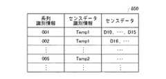
図9は、本実施形態に係るデータ記憶部850を示す。データ記憶部850は、センスデータの系列ごとに、当該系列を識別するための系列識別情報と、当該系列に含まれる1または複数のセンスデータと、センスデータを識別するためのセンスデータ識別情報とを対応付けて記憶する。 FIG. 9 shows a
ここで、本実施形態では一例として、センスデータの系列とは、一のセンサ装置200により経時的に測定されたセンスデータの集まりであり、系列識別情報とは、系列を識別するための情報である。そのため、センサ装置200が交換された場合には、交換前のセンサ装置200からのセンスデータと、交換後のセンサ装置からのセンスデータとに対し、別々の系列識別情報が対応付けられる。これに対し、センスデータ識別情報は、センサ装置200の設置位置および測定物理量に固有の識別情報である。そのため、センサ装置200が交換された場合には、交換前のセンサ装置200からのセンスデータと、交換後のセンサ装置200からのセンスデータとに対し同一のセンスデータ識別情報が対応づけられる。一例として、図9では、1行目および2行目の系列のセンスデータが、交換前後の別個のセンサ装置200により測定されているため、異なる系列識別情報「001」,「002」に対応付けられ、かつ、同一のセンスデータ識別情報「Temp1」に対応付けられている。なお、本実施形態では一例としてセンスデータは一定周期での測定期間ごとの測定結果を含むデータであるが、測定期間全体での測定結果を含むデータでもよい。 Here, as an example in the present embodiment, the sense data sequence is a collection of sense data measured over time by one
以上のデータ記憶部850によれば、交換前のセンサ装置200からのセンスデータと、交換後のセンサ装置200からのセンスデータとに異なる系列識別情報が対応付けられて記憶されるので、別々のセンサ装置200からのセンスデータであることを容易に把握することができる。 According to the above
図10は、本実施形態に係るデバイス管理DB820を示す。デバイス管理DB820は、センスデータの系列識別情報と、センスデータ識別情報と、センスデータのメタデータとを対応付けて記憶する。メタデータは、センサ装置200のデバイス識別情報と、センサ装置200の状態情報とを含む。これにより、デバイス管理DB820では、基盤システム160に登録された各センサ装置200に対応付けてセンスデータ識別情報が記憶される。なお、図10では、1行目および2行目の系列に対応するセンスデータが、交換前後のセンサ装置200により測定されているため、別々のデバイス識別情報「S01」,「S02」が同一のセンスデータ識別情報「Temp1」に対応付けられている。また、交換前のセンサ装置200の状態情報は、当該センサ装置200が非アクティブであることを示し、交換後のセンサ装置200の状態情報は、当該センサ装置200がアクティブであることを示している。 FIG. 10 shows the
図11は、本実施形態に係る基盤システム160の処理フローを示す。S900において、ユーザログイン処理部860は、テナントのユーザ等が使用する端末165からのログインを受け付ける。ユーザログイン処理部860は、端末165から受け取ったログインIDおよびパスワードに基づくユーザ認証を行い、正しく認証されたことに応じてそのログインIDに対応するテナントのアカウントへのログインを行わせる。 FIG. 11 shows a processing flow of the
S910において、アプリケーション処理部870は、基盤システム160を介してアプリケーションの開発環境を提供し、テナントのユーザがネットワークシステム用のアプリケーションを開発するのを支援する。例えば、アプリケーション処理部870は、アプリケーションで使用する各ネットワークデバイス100の選択、各ネットワークデバイス100からのデータを変換するために用いるデータ変換器840の選択、各ネットワークデバイス100からのデータに対する処理・制御演算を行うロジックの作成・記述、アプリケーションの処理結果を端末165に表示するためのウィジェット等の作成・選択、端末165の表示レイアウトの作成、および各種のテンプレートの選択等を行うことができる開発環境を提供する。 In S910, the
S920において、アプリケーション処理部870は、端末165を介してユーザからアプリケーションの実行指示を入力する。S930において、デバイスネットワーク管理部800は、複数のネットワークデバイス100のそれぞれからデータを取得する。例えば、デバイスネットワーク管理部800は、各ネットワークデバイス100に対してデータの読出要求を予め指定された周期で送信して、各ネットワークデバイス100からデータを収集してよい。これに代えて、各ネットワークデバイス100は、予め定められた周期で宛先情報記憶領域216に登録された基盤システム160の宛先へとデータを送信し、デバイスネットワーク管理部800は、各ネットワークデバイス100から送信されたデータを受信してもよい。ここで、各ネットワークデバイス100は、各ネットワークデバイス100が有する秘密鍵でデータを暗号化して基盤システム160へと送信し、デバイスネットワーク管理部800は、各ネットワークデバイス100からのデータを各ネットワークデバイス100の公開鍵で復号化して取得してよい。これにより、各ネットワークデバイス100が送信するセンスデータが傍受されるのを防ぐことができる。 In S920, the
S940において、デバイスルータ830は、各ネットワークデバイス100から受信したデータを、各ネットワークデバイス100に割り当てられたデータ変換器840へとルーティングする。S950において、ネットワークデバイス100からのデータを受け取ったデータ変換器840は、そのデータ変換器840に対応するデータ変換を行う。このようなデータ変換は、例えば、温度センサから取得された温度データ値を摂氏温度を表すデータ形式に変換することであってもよいし、センサから取得されたセンスデータの平滑化、積分および微分等の何れかを行うこと等のような、ネットワークデバイス100からのデータをアプリケーション処理部870が実行するアプリケーションで要求される任意のデータ形式に変換するものであってよい。 In S940, the
S960において、データ変換器840によって変換されたデータをデータ記憶部850に記憶する。データ記憶部850は、変換されたデータを、センスデータの系列ごとにセンスデータ識別情報に対応付けて記憶してよい。S970において、アプリケーション処理部870は、実行中のアプリケーションに実装されたアルゴリズム等にしたがって、データ記憶部850に記憶されたデータを用いたアプリケーション処理を行う。 In S960, the data converted by the
S980において、アプリケーション処理部870は、アプリケーションの処理結果を表示する表示画面を端末165へと出力し、端末165により処理結果を端末165のユーザへと表示させる。アプリケーションの内容によっては、アプリケーション処理部870は、時間の経過に応じて変化していく各ネットワークデバイス100からのデータに応じて、継続的に端末165への表示画面を更新していく。 In S980, the
以上に示した基盤システム160によれば、プロビジョニングシステム120およびプロビジョニングシステム140によるプロビジョニングサービスを用いてセキュアに設置された納入対象ネットワークデバイス100に対してネットワークシステム構築サービスに接続するための暗号鍵を配布する。これにより、基盤システム160は、不正なネットワークデバイス100がネットワークシステム構築サービスに接続するのを防ぐことができ、セキュアなアプリケーション開発・実行環境を提供することができる。 According to the
図12は、第1センサ装置200が第2センサ装置200に交換された場合の端末150、プロビジョニングシステム140および基盤システム160の処理フローを示す。この処理フローは、テナントのユーザによって第1センサ装置200が第2センサ装置200に交換された場合に実行される。一例として、この処理フローは、交換元の第1センサ装置200がネットワーク145から切り離され、交換先の第2センサ装置200がネットワーク145に接続されてパワーオンした後に実行されてよい。 FIG. 12 shows a processing flow of the terminal 150, the
S735'において端末150内の識別情報取得部675は、交換前後の第1センサ装置200および第2センサ装置200のそれぞれの本体または付属品からデバイス識別情報を取得する。例えば、識別情報取得部675は、第1センサ装置200および第2センサ装置200のコードラベル102を撮像し、撮像画像に含まれるコードを認識してコーディングされたデバイス識別情報、パスコード、およびプロビジョニングシステム140の宛先情報を復元する。 In S735', the identification
識別情報取得部675は、第1センサ装置200および第2センサ装置200のデバイス識別情報等を交換元および交換先として区別せずに取得してもよいし、区別して取得してもよい。また、識別情報取得部675は、第1センサ装置200のコードラベル102、および第2センサ装置200のコードラベル102を同時に撮像してもよいし、いずれか一方を先に、他方を後に撮像してもよい。一例として、識別情報取得部675は、複数のコードラベル102をまとめて撮像して第1センサ装置200および第2センサ装置200のデバイス識別情報をいっぺんに取得してよい。これに代えて、端末150の表示画面には、交換元の第1センサ装置200のコードラベル102の撮像を促すメッセージ、および、交換先の第2センサ装置200のコードラベル102の撮像を促すメッセージが順に表示されてよく、識別情報取得部675は、前者のメッセージの表示中に撮像されたコードラベル102から取得されるデバイス識別情報を交換元の第1センサ装置200のデバイス識別情報とし、後者のメッセージの表示中に撮像されたコードラベル102から取得されるデバイス識別情報を交換先の第2センサ装置200のデバイス識別情報としてよい。識別情報取得部675は、第1センサ装置200のコードラベル102からはデバイス識別情報のみを取得し、パスコードなどを取得しなくてもよい。識別情報取得部675は、端末150に対する入力操作によって第1センサ装置200のデバイス識別情報を取得してもよい。一例として、端末150とプロビジョニングシステム140または基盤システム160とが通信を行うことにより、端末150の表示画面にはデバイス管理DB820に登録済みのアクティブなセンサ装置200のリストが表示されてよく、識別情報取得部675は、交換元の第1センサ装置200としてユーザに選択されたセンサ装置200のデバイス識別情報をデバイスDB615またはデバイス管理DB820から取得してよい。これにより、交換元の第1センサ装置200のコードラベル102が破損して、撮像によりデバイス識別情報が取得できない場合であっても、ユーザによる入力操作によって第1センサ装置200のデバイス識別情報を取得することができる。 The identification
端末150内の識別情報送信部680は、識別情報取得部675が取得したデバイス識別情報等を、識別情報取得部675が取得した宛先情報によって指定されるプロビジョニングシステム140へと送信する。識別情報取得部675が第1センサ装置200および第2センサ装置200を交換元および交換先として区別してデバイス識別情報などを取得した場合には、識別情報送信部680は、これらを区別してプロビジョニングシステム140に送信してよい。なお、S735'の処理では、上述のS735の処理とは異なり、識別情報取得部675がセンスデータ識別情報を生成して識別情報送信部680が当該センスデータ識別情報をプロビジョニングシステム140に送信する処理を行わなくてよい。端末150は、S735'の処理が完了したら上述のS746(図7参照)に処理を移行してよい。 The identification
S740'において、プロビジョニングシステム140内の識別情報受信部630は、端末150からデバイス識別情報等を受信する。プロビジョニングシステム140内のアクティベーション処理部635は、受信されたデバイス識別情報に対応する第1センサ装置200,第2センサ装置200のディアクティベーション,アクティベーションを基盤システム160に要求する。一例として、アクティベーション処理部635は、第1センサ装置200および第2センサ装置200の一方をディアクティベーションの対象、他方をアクティベーションの対象として区別してディアクティベーションおよびアクティベーションを行うよう基盤システム160に要求してよい。これに代えて、アクティベーション処理部635は、識別情報受信部630が受信したデバイス識別情報のうち、既にデバイスDB615に記憶されている一方のデバイス識別情報を交換元の第1センサ装置200のデバイス識別情報として特定するよう要求し、第1センサ装置200をディアクティベートするよう要求してよい。また、アクティベーション処理部635は、他方のデバイス識別情報を交換先の第2センサ装置200のデバイス識別情報として特定するよう要求し、上述のS740と同様にして第2センサ装置200をアクティベートするよう要求してよい。プロビジョニングシステム140は、S740'の処理が完了したら上述のS744(図7参照)に処理を移行してよい。 In S740', the identification
S742'においてプロビジョニングシステム140から要求を受けた基盤システム160は、第1センサ装置200,第2センサ装置200のディアクティベーション,アクティベーションを行う。例えば、基盤システム160のデバイス識別情報取得部881は、第1センサ装置200および第2センサ装置200から端末150が取得したデバイス識別情報等の組を受信する。基盤システム160の状態取得部882は、2つのデバイス識別情報のそれぞれに対応するセンサ装置200の状態情報(一例としてアクティブおよび非アクティブのいずれであるかを示す情報)をデバイス管理DB820から取得する。基盤システム160のデバイス特定部883は、デバイス識別情報取得部881により取得された2つのデバイス識別情報のうち、アクティブなセンサ装置200に対応付けられたデバイス識別情報を交換元の第1センサ装置200の第1デバイス識別情報として特定し、アクティブでない(一例として状態情報が登録されていない)センサ装置200に対応付けられたデバイス識別情報を交換先の第2センサ装置200の第2デバイス識別情報として特定する。そして、基盤システム160の交換処理部880は、デバイス管理DB820において第1デバイス識別情報に対応づけられた交換元の第1センサ装置200の状態情報を非アクティブにし、第1センサ装置200をディアクティベートする。交換処理部880は、デバイス管理DB820において第1デバイス識別情報に対応する交換元の第1センサ装置200のレコードを削除することで第1センサ装置200をディアクティベートしてもよい。また、交換処理部880は、第2センサ装置200の第2デバイス識別情報等と、第1センサ装置200に対応付けられていたセンスデータ識別情報とを対応付けてデバイス管理DB820に格納する。また、交換処理部880は、デバイス管理DB820において第2デバイス識別情報に対応づけられた交換先の第2センサ装置200の状態情報をアクティブにする。また、交換処理部880は、第2センサ装置200により出力されるセンスデータの格納領域に対応付けて第1センスデータ識別情報を記憶する。 The
基盤システム160は第2センサ装置200のデバイス情報が正常に登録されたことをプロビジョニングシステム140に通知して、上述のS754(図7参照)に処理を移行してよい。なお、プロビジョニングシステム140が第1センサ装置200および第2センサ装置200を区別してディアクティベーションおよびアクティベーションを要求した場合には、交換処理部880は、第1センサ装置200をディアクティベーションの対象、第2センサ装置200をアクティベーションの対象としてよい。この場合、交換処理部880には状態取得部882およびデバイス特定部883が具備されなくてもよい。 The
以上の動作によれば、端末150によって第1センサ装置200,第2センサ装置200から取得された第1デバイス識別情報,第2デバイス識別情報の組が基盤システム160に取得されるので、交換前後のセンサ装置200のセンサ装置識別情報を確実に取得することができる。また、撮像して取得された第1デバイス識別情報および第2デバイス識別情報が端末150から受信されるので、第1デバイス識別情報および第2デバイス識別情報の組を容易に取得することができる。 According to the above operation, since the set of the first device identification information and the second device identification information acquired from the
なお、上記の実施形態では、端末150がセンスデータ識別情報を生成することとして説明したが、プロビジョニングシステム140が生成してもよいし、基盤システム160が生成してもよい。 Although the terminal 150 has been described as generating the sense data identification information in the above embodiment, the
また、基盤システム160のデバイス識別情報取得部881は、端末150の識別情報取得部675によってコードラベル102の撮像画像から認識されたデバイス識別情報等を取得することとして説明したが、コードラベル102の撮像画像を取得してデバイス識別情報等を認識してもよい。 Further, although the device identification
本発明の様々な実施形態は、フローチャートおよびブロック図を参照して記載されてよく、ここにおいてブロックは、(1)操作が実行されるプロセスの段階または(2)操作を実行する役割を持つ装置のセクションを表わしてよい。特定の段階およびセクションが、専用回路、コンピュータ可読媒体上に格納されるコンピュータ可読命令と共に供給されるプログラマブル回路、およびコンピュータ可読媒体上に格納されるコンピュータ可読命令と共に供給されるプロセッサのいずれかによって実装されてよい。専用回路は、デジタルおよびアナログのいずれかのハードウェア回路を含んでよく、集積回路(IC)およびはディスクリート回路の何れかを含んでよい。プログラマブル回路は、論理AND、論理OR、論理XOR、論理NAND、論理NOR、および他の論理操作、フリップフロップ、レジスタ、フィールドプログラマブルゲートアレイ(FPGA)、プログラマブルロジックアレイ(PLA)等のようなメモリ要素等を含む、再構成可能なハードウェア回路を含んでよい。 Various embodiments of the present invention may be described with reference to flowcharts and block diagrams, wherein the block is (1) a stage of the process in which the operation is performed or (2) a device responsible for performing the operation. May represent a section of. Specific stages and sections are implemented by either a dedicated circuit, a programmable circuit supplied with computer-readable instructions stored on a computer-readable medium, or a processor supplied with computer-readable instructions stored on a computer-readable medium. May be done. Dedicated circuits may include either digital or analog hardware circuits, and may include either integrated circuits (ICs) and discrete circuits. Programmable circuits are memory elements such as logical AND, logical OR, logical XOR, logical NAND, logical NOR, and other logical operations, flip-flops, registers, field programmable gate arrays (FPGA), programmable logic arrays (PLA), etc. May include reconfigurable hardware circuits, including, etc.
コンピュータ可読媒体は、適切なデバイスによって実行される命令を格納可能な任意の有形なデバイスを含んでよく、その結果、そこに格納される命令を有するコンピュータ可読媒体は、フローチャートまたはブロック図で指定された操作を実行するための手段を作成すべく実行され得る命令を含む、製品を備えることになる。コンピュータ可読媒体の例としては、電子記憶媒体、磁気記憶媒体、光記憶媒体、電磁記憶媒体、半導体記憶媒体等が含まれてよい。コンピュータ可読媒体のより具体的な例としては、フロッピー(登録商標)ディスク、ディスケット、ハードディスク、ランダムアクセスメモリ(RAM)、リードオンリメモリ(ROM)、消去可能プログラマブルリードオンリメモリ(EPROMまたはフラッシュメモリ)、電気的消去可能プログラマブルリードオンリメモリ(EEPROM)、静的ランダムアクセスメモリ(SRAM)、コンパクトディスクリードオンリメモリ(CD-ROM)、デジタル多用途ディスク(DVD)、ブルーレイ(RTM)ディスク、メモリスティック、集積回路カード等が含まれてよい。 The computer readable medium may include any tangible device capable of storing instructions executed by the appropriate device, so that the computer readable medium having the instructions stored therein is specified in a flowchart or block diagram. It will be equipped with a product that contains instructions that can be executed to create means for performing the operation. Examples of computer-readable media may include electronic storage media, magnetic storage media, optical storage media, electromagnetic storage media, semiconductor storage media, and the like. More specific examples of computer-readable media include floppy (registered trademark) disks, diskettes, hard disks, random access memory (RAM), read-only memory (ROM), erasable programmable read-only memory (EPROM or flash memory), Electrically erasable programmable read-only memory (EEPROM), static random access memory (SRAM), compact disc read-only memory (CD-ROM), digital versatile disc (DVD), Blu-ray (RTM) disc, memory stick, integrated A circuit card or the like may be included.
コンピュータ可読命令は、アセンブラ命令、命令セットアーキテクチャ(ISA)命令、マシン命令、マシン依存命令、マイクロコード、ファームウェア命令、状態設定データ、またはSmalltalk、JAVA(登録商標)、C++等のようなオブジェクト指向プログラミング言語、および「C」プログラミング言語または同様のプログラミング言語のような従来の手続型プログラミング言語を含む、1または複数のプログラミング言語の任意の組み合わせで記述されたソースコードまたはオブジェクトコードのいずれかを含んでよい。 Computer-readable instructions are assembler instructions, instruction set architecture (ISA) instructions, machine instructions, machine-dependent instructions, microcode, firmware instructions, state-setting data, or object-oriented programming such as Smalltalk, JAVA®, C ++, etc. Contains either source code or object code written in any combination of one or more programming languages, including languages and traditional procedural programming languages such as the "C" programming language or similar programming languages. good.
コンピュータ可読命令は、汎用コンピュータ、特殊目的のコンピュータ、若しくは他のプログラム可能なデータ処理装置のプロセッサまたはプログラマブル回路に対し、ローカルにまたはローカルエリアネットワーク(LAN)、インターネット等のようなワイドエリアネットワーク(WAN)を介して提供され、フローチャートまたはブロック図で指定された操作を実行するための手段を作成すべく、コンピュータ可読命令を実行してよい。プロセッサの例としては、コンピュータプロセッサ、処理ユニット、マイクロプロセッサ、デジタル信号プロセッサ、コントローラ、マイクロコントローラ等を含む。 Computer-readable instructions are applied locally to a general purpose computer, a special purpose computer, or the processor or programmable circuit of another programmable data processing unit, or to a wide area network (WAN) such as the local area network (LAN), the Internet, etc. ) May be executed to create a means for performing the operation specified in the flowchart or block diagram. Examples of processors include computer processors, processing units, microprocessors, digital signal processors, controllers, microcontrollers and the like.
図13は、本発明の複数の態様が全体的または部分的に具現化されてよいコンピュータ2200の例を示す。コンピュータ2200にインストールされたプログラムは、コンピュータ2200に、本発明の実施形態に係る装置に関連付けられる操作または当該装置の1または複数のセクションとして機能させることができてもよいし、または当該操作または当該1または複数のセクションを実行させることができてもよいし、コンピュータ2200に、本発明の実施形態に係るプロセスまたは当該プロセスの段階を実行させることができてもよい。そのようなプログラムは、コンピュータ2200に、本明細書に記載のフローチャートおよびブロック図のブロックのうちのいくつかまたはすべてに関連付けられた特定の操作を実行させるべく、CPU2212によって実行されてよい。 FIG. 13 shows an example of a
本実施形態によるコンピュータ2200は、CPU2212、RAM2214、グラフィックコントローラ2216、およびディスプレイデバイス2218を含み、それらはホストコントローラ2210によって相互に接続されている。コンピュータ2200はまた、通信インターフェイス2222、ハードディスクドライブ2224、DVD−ROMドライブ2226、およびICカードドライブのような入出力ユニットを含み、それらは入出力コントローラ2220を介してホストコントローラ2210に接続されている。コンピュータはまた、ROM2230およびキーボード2242のようなレガシの入出力ユニットを含み、それらは入出力チップ2240を介して入出力コントローラ2220に接続されている。 The
CPU2212は、ROM2230およびRAM2214内に格納されたプログラムに従い動作し、それにより各ユニットを制御する。グラフィックコントローラ2216は、RAM2214内に提供されるフレームバッファ等またはそれ自体の中にCPU2212によって生成されたイメージデータを取得し、イメージデータがディスプレイデバイス2218上に表示されるようにする。 The
通信インターフェイス2222は、ネットワークを介して他の電子デバイスと通信する。ハードディスクドライブ2224は、コンピュータ2200内のCPU2212によって使用されるプログラムおよびデータを格納する。DVD−ROMドライブ2226は、プログラムまたはデータをDVD−ROM2201から読み取り、ハードディスクドライブ2224にRAM2214を介してプログラムまたはデータを提供する。ICカードドライブは、プログラムおよびデータをICカードから読み取り、プログラムおよびデータをICカードに書き込む。 The
ROM2230はその中に、アクティブ化時にコンピュータ2200によって実行されるブートプログラム等、およびコンピュータ2200のハードウェアに依存するプログラムのいずれかを格納する。入出力チップ2240はまた、様々な入出力ユニットをパラレルポート、シリアルポート、キーボードポート、マウスポート等を介して、入出力コントローラ2220に接続してよい。 The
プログラムが、DVD−ROM2201またはICカードのようなコンピュータ可読媒体によって提供される。プログラムは、コンピュータ可読媒体から読み取られ、コンピュータ可読媒体の例でもあるハードディスクドライブ2224、RAM2214、またはROM2230にインストールされ、CPU2212によって実行される。これらのプログラム内に記述される情報処理は、コンピュータ2200に読み取られ、プログラムと、上記様々なタイプのハードウェアリソースとの間の連携をもたらす。装置または方法が、コンピュータ2200の使用に従い情報の操作または処理を実現することによって構成されてよい。 The program is provided by a computer-readable medium such as a DVD-
例えば、通信がコンピュータ2200および外部デバイス間で実行される場合、CPU2212は、RAM2214にロードされた通信プログラムを実行し、通信プログラムに記述された処理に基づいて、通信インターフェイス2222に対し、通信処理を命令してよい。通信インターフェイス2222は、CPU2212の制御下、RAM2214、ハードディスクドライブ2224、DVD−ROM2201、またはICカードのような記録媒体内に提供される送信バッファ処理領域に格納された送信データを読み取り、読み取られた送信データをネットワークに送信し、またはネットワークから受信された受信データを記録媒体上に提供される受信バッファ処理領域等に書き込む。 For example, when communication is executed between the
また、CPU2212は、ハードディスクドライブ2224、DVD−ROMドライブ2226(DVD−ROM2201)、ICカード等のような外部記録媒体に格納されたファイルまたはデータベースの全部または必要な部分がRAM2214に読み取られるようにし、RAM2214上のデータに対し様々なタイプの処理を実行してよい。CPU2212は次に、処理されたデータを外部記録媒体にライトバックする。 Further, the
様々なタイプのプログラム、データ、テーブル、およびデータベースのような様々なタイプの情報が記録媒体に格納され、情報処理を受けてよい。CPU2212は、RAM2214から読み取られたデータに対し、本開示の随所に記載され、プログラムの命令シーケンスによって指定される様々なタイプの操作、情報処理、条件判断、条件分岐、無条件分岐、情報の検索および置換等のいずれかを含む、様々なタイプの処理を実行してよく、結果をRAM2214に対しライトバックする。また、CPU2212は、記録媒体内のファイル、データベース等における情報を検索してよい。例えば、各々が第2の属性の属性値に関連付けられた第1の属性の属性値を有する複数のエントリが記録媒体内に格納される場合、CPU2212は、第1の属性の属性値が指定される、条件に一致するエントリを当該複数のエントリの中から検索し、当該エントリ内に格納された第2の属性の属性値を読み取り、それにより予め定められた条件を満たす第1の属性に関連付けられた第2の属性の属性値を取得してよい。 Various types of information, such as various types of programs, data, tables, and databases, may be stored on the recording medium and processed. The
上で説明したプログラムまたはソフトウェアモジュールは、コンピュータ2200上またはコンピュータ2200近傍のコンピュータ可読媒体に格納されてよい。また、専用通信ネットワークまたはインターネットに接続されたサーバーシステム内に提供されるハードディスクまたはRAMのような記録媒体が、コンピュータ可読媒体として使用可能であり、それによりプログラムを、ネットワークを介してコンピュータ2200に提供する。 The program or software module described above may be stored on or near a
以上、本発明を実施の形態を用いて説明したが、本発明の技術的範囲は上記実施の形態に記載の範囲には限定されない。上記実施の形態に、多様な変更または改良を加えることが可能であることが当業者に明らかである。その様な変更または改良を加えた形態も本発明の技術的範囲に含まれ得ることが、特許請求の範囲の記載から明らかである。 Although the present invention has been described above using the embodiments, the technical scope of the present invention is not limited to the scope described in the above embodiments. It will be apparent to those skilled in the art that various changes or improvements can be made to the above embodiments. It is clear from the description of the claims that such modified or improved forms may also be included in the technical scope of the present invention.
特許請求の範囲、明細書、および図面中において示した装置、システム、プログラム、および方法における動作、手順、ステップ、および段階等の各処理の実行順序は、特段「より前に」、「先立って」等と明示しておらず、また、前の処理の出力を後の処理で用いるのでない限り、任意の順序で実現しうることに留意すべきである。特許請求の範囲、明細書、および図面中の動作フローに関して、便宜上「まず、」、「次に、」等を用いて説明したとしても、この順で実施することが必須であることを意味するものではない。 The order of execution of operations, procedures, steps, steps, etc. in the devices, systems, programs, and methods shown in the claims, specification, and drawings is particularly "before" and "prior to". It should be noted that it can be realized in any order unless the output of the previous process is used in the subsequent process. Even if the scope of claims, the specification, and the operation flow in the drawings are explained using "first", "next", etc. for convenience, it means that it is essential to carry out in this order. It's not a thing.
10 デバイスプロビジョニング環境、100 ネットワークデバイス、102 コードラベル、104 識別情報記憶領域、106 認証情報記憶領域、108 暗号鍵記憶領域、120 プロビジョニングシステム、125 ネットワーク、130 端末、135 プリンタ、140 プロビジョニングシステム、145 ネットワーク、150 端末、160 基盤システム、165 端末、200 センサ装置、210 設定記憶部、212 パスコード記憶領域、214 宛先情報記憶領域、216 宛先情報記憶領域、220 センサ、230 センスデータ取得部、240 センスデータ記憶部、250 アクセス制御部、260 ネットワークインターフェイス、262 設定格納処理部、264 デバイス認証処理部、266 暗号鍵受信部、268 サービス接続処理部、300 センサゲートウェイ装置、320 有線センサ接続部、330 無線センサ接続部、340 センスデータ記憶部、410 設定者ログイン処理部、415 識別情報決定部、420 デバイスDB、425 認証情報生成部、430 コード生成部、435 識別情報送信部、440 認証情報送信部、445 デバイス登録送信部、450 ログイン処理部、455 デバイス情報取得部、460 デバイス情報送信部、465 識別情報受信部、470 識別情報設定部、475 認証情報受信部、480 認証情報設定部、610 デバイス登録受信部、615 デバイスDB、620 デバイス認証部、625 テナントログイン処理部、630 識別情報受信部、635 アクティベーション処理部、640 デバイス登録要求部、645 暗号鍵取得部、650 基盤宛先取得部、655 暗号鍵送信部、660 基盤宛先送信部、670 ログイン処理部、675 識別情報取得部、680 識別情報送信部、685 アクティベーション結果通知部、800 デバイスネットワーク管理部、805 暗号鍵発行部、810 基盤宛先発行部、820 デバイス管理DB、830 デバイスルータ、840 データ変換器、850 データ記憶部、860 ユーザログイン処理部、870 アプリケーション処理部、880 交換処理部、881 デバイス識別情報取得部、882 状態取得部、883 デバイス特定部、2200 コンピュータ、2201 DVD−ROM、2210 ホストコントローラ、2212 CPU、2214 RAM、2216 グラフィックコントローラ、2218 ディスプレイデバイス、2220 入出力コントローラ、2222 通信インターフェイス、2224 ハードディスクドライブ、2226 DVD−ROMドライブ、2230 ROM、2240 入出力チップ、2242 キーボード10 device provisioning environment, 100 network devices, 102 code labels, 104 identification information storage, 106 authentication information storage, 108 encryption key storage, 120 provisioning system, 125 networks, 130 terminals, 135 printers, 140 provisioning systems, 145 networks , 150 terminal, 160 infrastructure system, 165 terminal, 200 sensor device, 210 setting storage unit, 212 passcode storage area, 214 destination information storage area, 216 destination information storage area, 220 sensor, 230 sense data acquisition unit, 240 sense data Storage unit, 250 access control unit, 260 network interface, 262 setting storage processing unit, 264 device authentication processing unit, 266 encryption key receiving unit, 268 service connection processing unit, 300 sensor gateway device, 320 wired sensor connection unit, 330 wireless sensor Connection unit, 340 sense data storage unit, 410 configurator login processing unit, 415 identification information determination unit, 420 device DB, 425 authentication information generation unit, 430 code generation unit, 435 identification information transmission unit, 440 authentication information transmission unit, 445 Device registration transmission unit, 450 login processing unit, 455 device information acquisition unit, 460 device information transmission unit, 465 identification information reception unit, 470 identification information setting unit, 475 authentication information reception unit, 480 authentication information setting unit, 610 device registration reception unit. Unit, 615 device DB, 620 device authentication unit, 625 tenant login processing unit, 630 identification information receiving unit, 635 activation processing unit, 640 device registration request unit, 645 encryption key acquisition unit, 650 infrastructure destination acquisition unit, 655 encryption key Transmission unit, 660 infrastructure destination transmission unit, 670 login processing unit, 675 identification information acquisition unit, 680 identification information transmission unit, 685 activation result notification unit, 800 device network management unit, 805 encryption key issuing unit, 810 infrastructure destination issuing unit , 820 device management DB, 830 device router, 840 data converter, 850 data storage unit, 860 user login processing unit, 870 application processing unit, 880 exchange processing unit, 8 81 Device identification information acquisition unit, 882 status acquisition unit, 883 device identification unit, 2200 computer, 2201 DVD-ROM, 2210 host controller, 2212 CPU, 2214 RAM, 2216 graphic controller, 2218 display device, 2220 input / output controller, 2222 communication Interface, 2224 hard disk drive, 2226 DVD-ROM drive, 2230 ROM, 2240 I / O chip, 2242 controller
Claims (12)
Translated fromJapanese前記複数のセンサ装置のそれぞれから受信されるセンスデータを、前記デバイス情報記憶部において各センサ装置に対応付けられたセンスデータ識別情報に対応付けて記憶するデータ記憶部と、
前記複数のセンサ装置のうち第1センサ装置が第2センサ装置に交換されることに応じて、前記デバイス情報記憶部において前記第1センサ装置に対応付けられた第1センスデータ識別情報を第2センサ装置に対応付ける第2センスデータ識別情報とする交換処理部と
を備え、
前記データ記憶部は、交換前の前記第1センサ装置からのセンスデータおよび交換後の前記第2センサ装置からのセンスデータに、同一のセンスデータ識別情報および異なる系列識別情報を対応付けて記憶する管理装置。A device information storage unit that stores sense data identification information that identifies sense data output by each sensor device in association with each of a plurality of sensor devices that communicate via a network.
A data storage unit that stores sense data received from each of the plurality of sensor devices in association with the sense data identification information associated with each sensor device in the device information storage unit.
In response to the replacement of the first sensor device with the second sensor device among the plurality of sensor devices, the device information storage unit secondly obtains the first sense data identification information associated with the first sensor device. Equipped with an exchange processing unit that serves as the second sense data identification information associated with the sensor device.
The data storage unit stores the same sense data identification information and different series identification information in association with the sense data from the first sensor device before the exchange and the sense data from the second sensor device after the exchange. Management device.
前記交換処理部は、交換元の前記第1センサ装置の第1デバイス識別情報に対応付けられた前記第1センスデータ識別情報を、交換先の前記第2センサ装置の第2デバイス識別情報に対応付けて前記デバイス情報記憶部に格納する
請求項1に記載の管理装置。The device information storage unit stores device identification information that identifies each of the plurality of sensor devices, and stores the device identification information.
The exchange processing unit corresponds the first sense data identification information associated with the first device identification information of the first sensor device of the exchange source to the second device identification information of the second sensor device of the exchange destination. The management device according to claim 1, which is attached and stored in the device information storage unit.
前記複数のセンサ装置のそれぞれから受信されるセンスデータを、前記デバイス情報記憶部において各センサ装置に対応付けられたセンスデータ識別情報に対応付けて記憶するデータ記憶部と、
前記複数のセンサ装置のうち第1センサ装置が第2センサ装置に交換されることに応じて、前記デバイス情報記憶部において前記第1センサ装置に対応付けられた第1センスデータ識別情報を第2センサ装置に対応付ける第2センスデータ識別情報とする交換処理部と
を備え、
前記デバイス情報記憶部は、前記複数のセンサ装置のそれぞれを識別するデバイス識別情報を記憶し、
前記交換処理部は、
端末によって前記第1センサ装置の本体または付属品から取得された第1デバイス識別情報と、前記端末によって前記第2センサ装置の本体または付属品から取得された第2デバイス識別情報との複数のデバイス識別情報を取得するデバイス識別情報取得部と、
前記複数のデバイス識別情報のそれぞれに対応するセンサ装置の状態を前記デバイス情報記憶部から取得する状態取得部と、
前記複数のデバイス識別情報のうち、アクティブなセンサ装置に対応付けられたデバイス識別情報を、交換元の前記第1センサ装置の前記第1デバイス識別情報として特定し、アクティブでないセンサ装置に対応付けられたデバイス識別情報を、交換先の前記第2センサ装置の前記第2デバイス識別情報として特定するデバイス特定部と
を有する管理装置。A device information storage unit that stores sense data identification information that identifies sense data output by each sensor device in association with each of a plurality of sensor devices that communicate via a network.
A data storage unit that stores sense data received from each of the plurality of sensor devices in association with the sense data identification information associated with each sensor device in the device information storage unit.
In response to the replacement of the first sensor device with the second sensor device among the plurality of sensor devices, the device information storage unit secondly obtains the first sense data identification information associated with the first sensor device. Equipped with an exchange processing unit that serves as the second sense data identification information associated with the sensor device.
The device information storage unit stores device identification information that identifies each of the plurality of sensor devices, and stores the device identification information.
The exchange processing unit
A plurality of devices of the first device identification information acquired from the main body or accessory of the first sensor device by the terminal and the second device identification information acquired from the main body or accessory of the second sensor device by the terminal. The device identification information acquisition unit that acquires identification information, and
A state acquisition unit that acquires the state of the sensor device corresponding to each of the plurality of device identification information from the device information storage unit, and a state acquisition unit.
Among the plurality of device identification information, the device identification information associated with the active sensor device is specified as the first device identification information of the exchange source first sensor device, and is associated with the inactive sensor device. With the device identification unit that specifies the device identification information as the second device identification information of the exchange destination second sensor device.
Management devicehaving a.
請求項3に記載の管理装置。Before SL exchange processing unit, the first sense data identification information associated withthe first device identification information of the replacement source of the first sensor device,the second device identification of the exchange destination of the second sensor unit The management device accordingto claim 3 , which is stored in the device information storage unit in association with information.
ネットワークを介して通信する複数のセンサ装置のそれぞれに対応付けて、各センサ装置が出力するセンスデータを識別するセンスデータ識別情報をデバイス情報記憶領域に記憶させる段階と、
前記複数のセンサ装置のそれぞれから受信されるセンスデータを、前記デバイス情報記憶領域において各センサ装置に対応付けられたセンスデータ識別情報に対応付けてデータ記憶領域に記憶させる段階と、
前記複数のセンサ装置のうち第1センサ装置が第2センサ装置に交換されることに応じて、前記デバイス情報記憶領域において前記第1センサ装置に対応付けられた第1センスデータ識別情報と同一のセンスデータ識別情報を第2センサ装置に対応付ける第2センスデータ識別情報とする段階と
を備え、
前記データ記憶領域に記憶させる段階では、交換前の前記第1センサ装置からのセンスデータおよび交換後の前記第2センサ装置からのセンスデータに、同一のセンスデータ識別情報および異なる系列識別情報を対応付けて前記データ記憶領域に記憶させる管理方法。It ’s a management method,
A step of storing the sense data identification information for identifying the sense data output by each sensor device in the device information storage area in association with each of the plurality of sensor devices communicating via the network.
A step of storing sense data received from each of the plurality of sensor devices in the data storage area in association with the sense data identification information associated with each sensor device in the device information storage area.
When the first sensor device is replaced with the second sensor device among the plurality of sensor devices, it is the same as the first sense data identification information associated with the first sensor device in the device information storage area. It is provided with a step of converting the sense data identification information into the second sense data identification information associated with the second sensor device.
At the stage of storing in the data storage area, the same sense data identification information and different series identification information correspond to the sense data from the first sensor device before the exchange and the sense data from the second sensor device after the exchange. wherein the data storage area management method Ruis stored in wearing.
ネットワークを介して通信する複数のセンサ装置のそれぞれに対応付けて、各センサ装置が出力するセンスデータを識別するセンスデータ識別情報をデバイス情報記憶領域に記憶させる段階と、
前記複数のセンサ装置のそれぞれから受信されるセンスデータを、前記デバイス情報記憶領域において各センサ装置に対応付けられたセンスデータ識別情報に対応付けてデータ記憶領域に記憶させる段階と、
前記複数のセンサ装置のうち第1センサ装置が第2センサ装置に交換されることに応じて、前記デバイス情報記憶領域において前記第1センサ装置に対応付けられた第1センスデータ識別情報と同一のセンスデータ識別情報を第2センサ装置に対応付ける第2センスデータ識別情報とする交換処理段階と
を備え、
デバイス情報記憶領域に記憶させる段階では、前記複数のセンサ装置のそれぞれを識別するデバイス識別情報を記憶させ、
前記交換処理段階は、
端末によって前記第1センサ装置の本体または付属品から取得された第1デバイス識別情報と、前記端末によって前記第2センサ装置の本体または付属品から取得された第2デバイス識別情報との複数のデバイス識別情報を取得する段階と、
前記複数のデバイス識別情報のそれぞれに対応するセンサ装置の状態を前記デバイス情報記憶領域から取得する段階と、
前記複数のデバイス識別情報のうち、アクティブなセンサ装置に対応付けられたデバイス識別情報を、交換元の前記第1センサ装置の前記第1デバイス識別情報として特定し、アクティブでないセンサ装置に対応付けられたデバイス識別情報を、交換先の前記第2センサ装置の前記第2デバイス識別情報として特定する段階と
を有する管理方法。It ’s a management method,
A step of storing the sense data identification information for identifying the sense data output by each sensor device in the device information storage area in association with each of the plurality of sensor devices communicating via the network.
A step of storing sense data received from each of the plurality of sensor devices in the data storage area in association with the sense data identification information associated with each sensor device in the device information storage area.
When the first sensor device is replaced with the second sensor device among the plurality of sensor devices, it is the same as the first sense data identification information associated with the first sensor device in the device information storage area.It is provided with an exchange processing stage in which the sense data identification information is used as the second sense data identification information associated with the second sensor device.
At the stage of storing in the device information storage area, device identification information for identifying each of the plurality of sensor devices is stored.
The exchange processing step is
A plurality of devices of the first device identification information acquired from the main body or accessory of the first sensor device by the terminal and the second device identification information acquired from the main body or accessory of the second sensor device by the terminal. The stage of acquiring identification information and
The stage of acquiring the state of the sensor device corresponding to each of the plurality of device identification information from the device information storage area, and
Among the plurality of device identification information, the device identification information associated with the active sensor device is specified as the first device identification information of the exchange source first sensor device, and is associated with the inactive sensor device. The step of identifying the device identification information as the second device identification information of the second sensor device to be exchanged.
Management howhaving a.
ネットワークを介して通信する複数のセンサ装置のそれぞれに対応付けて、各センサ装置が出力するセンスデータを識別するセンスデータ識別情報を記憶するデバイス情報記憶部と、
前記複数のセンサ装置のそれぞれから受信されるセンスデータを、前記デバイス情報記憶部において各センサ装置に対応付けられたセンスデータ識別情報に対応付けて記憶するデータ記憶部と、
前記複数のセンサ装置のうち第1センサ装置が第2センサ装置に交換されることに応じて、前記デバイス情報記憶部において前記第1センサ装置に対応付けられた第1センスデータ識別情報を第2センサ装置に対応付ける第2センスデータ識別情報とする交換処理部、
として機能させ、
前記データ記憶部は、交換前の前記第1センサ装置からのセンスデータおよび交換後の前記第2センサ装置からのセンスデータに、同一のセンスデータ識別情報および異なる系列識別情報を対応付けて記憶するプログラム。Computer,
A device information storage unit that stores sense data identification information that identifies sense data output by each sensor device in association with each of a plurality of sensor devices that communicate via a network.
A data storage unit that stores sense data received from each of the plurality of sensor devices in association with the sense data identification information associated with each sensor device in the device information storage unit.
In response to the replacement of the first sensor device with the second sensor device among the plurality of sensor devices, the device information storage unit secondly obtains the first sense data identification information associated with the first sensor device. Exchange processing unit that serves as the second sense data identification information associated with the sensor device,
To functionas,
The data storage unit stores the same sense data identification information and different series identification information in association with the sense data from the first sensor device before the exchange and the sense data from the second sensor device after the exchange. Program.
ネットワークを介して通信する複数のセンサ装置のそれぞれに対応付けて、各センサ装置が出力するセンスデータを識別するセンスデータ識別情報を記憶するデバイス情報記憶部と、
前記複数のセンサ装置のそれぞれから受信されるセンスデータを、前記デバイス情報記憶部において各センサ装置に対応付けられたセンスデータ識別情報に対応付けて記憶するデータ記憶部と、
前記複数のセンサ装置のうち第1センサ装置が第2センサ装置に交換されることに応じて、前記デバイス情報記憶部において前記第1センサ装置に対応付けられた第1センスデータ識別情報を第2センサ装置に対応付ける第2センスデータ識別情報とする交換処理部、
として機能させ、
前記デバイス情報記憶部は、前記複数のセンサ装置のそれぞれを識別するデバイス識別情報を記憶し、
前記交換処理部は、
端末によって前記第1センサ装置の本体または付属品から取得された第1デバイス識別情報と、前記端末によって前記第2センサ装置の本体または付属品から取得された第2デバイス識別情報との複数のデバイス識別情報を取得するデバイス識別情報取得部と、
前記複数のデバイス識別情報のそれぞれに対応するセンサ装置の状態を前記デバイス情報記憶部から取得する状態取得部と、
前記複数のデバイス識別情報のうち、アクティブなセンサ装置に対応付けられたデバイス識別情報を、交換元の前記第1センサ装置の前記第1デバイス識別情報として特定し、アクティブでないセンサ装置に対応付けられたデバイス識別情報を、交換先の前記第2センサ装置の前記第2デバイス識別情報として特定するデバイス特定部と
を有するプログラム。Computer,
A device information storage unit that stores sense data identification information that identifies sense data output by each sensor device in association with each of a plurality of sensor devices that communicate via a network.
A data storage unit that stores sense data received from each of the plurality of sensor devices in association with the sense data identification information associated with each sensor device in the device information storage unit.
In response to the replacement of the first sensor device with the second sensor device among the plurality of sensor devices, the device information storage unit secondly obtains the first sense data identification information associated with the first sensor device. Exchange processing unit that serves as the second sense data identification information associated with the sensor device,
To functionas,
The device information storage unit stores device identification information that identifies each of the plurality of sensor devices, and stores the device identification information.
The exchange processing unit
A plurality of devices of the first device identification information acquired from the main body or accessory of the first sensor device by the terminal and the second device identification information acquired from the main body or accessory of the second sensor device by the terminal. The device identification information acquisition unit that acquires identification information, and
A state acquisition unit that acquires the state of the sensor device corresponding to each of the plurality of device identification information from the device information storage unit, and a state acquisition unit.
Among the plurality of device identification information, the device identification information associated with the active sensor device is specified as the first device identification information of the exchange source first sensor device, and is associated with the inactive sensor device. With the device identification unit that specifies the device identification information as the second device identification information of the exchange destination second sensor device.
A program thatYusuke.
Priority Applications (5)
| Application Number | Priority Date | Filing Date | Title |
|---|---|---|---|
| JP2018087175AJP6927136B2 (en) | 2018-04-27 | 2018-04-27 | Management equipment, management methods and programs |
| CN201980019331.0ACN111869188A (en) | 2018-04-27 | 2019-04-24 | Management equipment, management methods and procedures |
| PCT/JP2019/017425WO2019208630A1 (en) | 2018-04-27 | 2019-04-24 | Management device, management method, and program |
| EP19725424.6AEP3769496A1 (en) | 2018-04-27 | 2019-04-24 | Management device, management method, and program |
| US17/023,422US20210005331A1 (en) | 2018-04-27 | 2020-09-17 | Management device, management method, and program |
Applications Claiming Priority (1)
| Application Number | Priority Date | Filing Date | Title |
|---|---|---|---|
| JP2018087175AJP6927136B2 (en) | 2018-04-27 | 2018-04-27 | Management equipment, management methods and programs |
Publications (2)
| Publication Number | Publication Date |
|---|---|
| JP2021057624A JP2021057624A (en) | 2021-04-08 |
| JP6927136B2true JP6927136B2 (en) | 2021-08-25 |
Family
ID=66625228
Family Applications (1)
| Application Number | Title | Priority Date | Filing Date |
|---|---|---|---|
| JP2018087175AActiveJP6927136B2 (en) | 2018-04-27 | 2018-04-27 | Management equipment, management methods and programs |
Country Status (5)
| Country | Link |
|---|---|
| US (1) | US20210005331A1 (en) |
| EP (1) | EP3769496A1 (en) |
| JP (1) | JP6927136B2 (en) |
| CN (1) | CN111869188A (en) |
| WO (1) | WO2019208630A1 (en) |
Families Citing this family (9)
| Publication number | Priority date | Publication date | Assignee | Title |
|---|---|---|---|---|
| CN111581187B (en)* | 2020-05-14 | 2023-06-30 | 海南电网有限责任公司信息通信分公司 | Data management method, device, computer equipment and storage medium of smart park |
| CN111866728B (en)* | 2020-09-23 | 2021-02-05 | 深圳市速腾聚创科技有限公司 | Multi-site roadbed network sensing method, device, terminal and system |
| JP7631811B2 (en)* | 2021-01-08 | 2025-02-19 | オムロンヘルスケア株式会社 | Sensing data management system, sensing data transmission method, sensing device, information communication terminal, and program |
| US11652625B2 (en)* | 2021-06-11 | 2023-05-16 | Motorola Solutions, Inc. | Touchless key provisioning operation for communication devices |
| JP7528876B2 (en)* | 2021-06-25 | 2024-08-06 | 横河電機株式会社 | DATA PROCESSING APPARATUS, DATA PROCESSING METHOD, AND DATA PROCESSING PROGRAM |
| US11985228B2 (en)* | 2021-07-30 | 2024-05-14 | Cisco Technology, Inc. | Configuration payload separation policies |
| CN114268650B (en)* | 2021-12-20 | 2024-07-02 | 中国电信股份有限公司 | Configuration method and system for establishing communication connection |
| EP4227797B1 (en)* | 2022-02-14 | 2024-10-02 | VEGA Grieshaber KG | Method for generating a twin sensor using parameter inheritance and a sensor, a mobile device and a system for the same |
| CN119293042B (en)* | 2024-10-18 | 2025-08-08 | 南京威翔科技有限公司 | Method and device for processing sensor information of inertial navigation system |
Family Cites Families (6)
| Publication number | Priority date | Publication date | Assignee | Title |
|---|---|---|---|---|
| JP3518374B2 (en)* | 1998-11-12 | 2004-04-12 | トヨタ自動車株式会社 | Tire pressure monitoring device |
| US7970830B2 (en) | 2009-04-01 | 2011-06-28 | Honeywell International Inc. | Cloud computing for an industrial automation and manufacturing system |
| CN104354545B (en)* | 2014-10-17 | 2017-01-11 | 同致电子科技(厦门)有限公司 | Automatic learning method and system for tire pressure monitoring system |
| US11116397B2 (en)* | 2015-07-14 | 2021-09-14 | Welch Allyn, Inc. | Method and apparatus for managing sensors |
| US10078655B2 (en)* | 2015-09-28 | 2018-09-18 | International Business Machines Corporation | Reconciling sensor data in a database |
| US10037632B2 (en)* | 2016-09-01 | 2018-07-31 | Ford Global Technologies, Llc | Surrogate vehicle sensors |
- 2018
- 2018-04-27JPJP2018087175Apatent/JP6927136B2/enactiveActive
- 2019
- 2019-04-24EPEP19725424.6Apatent/EP3769496A1/ennot_activeWithdrawn
- 2019-04-24CNCN201980019331.0Apatent/CN111869188A/enactivePending
- 2019-04-24WOPCT/JP2019/017425patent/WO2019208630A1/ennot_activeCeased
- 2020
- 2020-09-17USUS17/023,422patent/US20210005331A1/ennot_activeAbandoned
Also Published As
| Publication number | Publication date |
|---|---|
| US20210005331A1 (en) | 2021-01-07 |
| EP3769496A1 (en) | 2021-01-27 |
| CN111869188A (en) | 2020-10-30 |
| WO2019208630A1 (en) | 2019-10-31 |
| JP2021057624A (en) | 2021-04-08 |
Similar Documents
| Publication | Publication Date | Title |
|---|---|---|
| JP6927136B2 (en) | Management equipment, management methods and programs | |
| CN208580402U (en) | Storage devices and stations for storage devices | |
| JP6702347B2 (en) | Provisioning system, provisioning method, provisioning program, and network device | |
| US20150253761A1 (en) | System and method for controlling manufacturing of an item | |
| JP2014095969A (en) | Network printing system and network printing program | |
| JP6991773B2 (en) | Systems, device management systems, and methods | |
| JP6387704B2 (en) | Information processing system, information processing method, terminal device, and program | |
| US10033905B2 (en) | Information processing system, management device, and information output method | |
| JP2015172824A (en) | Information processing system and authentication information providing method | |
| JP2008181178A (en) | Network output system, authentication information registration method, and authentication information registration program | |
| JP6349783B2 (en) | Terminal device, server device, device driver program, and external peripheral device control method | |
| JP5668805B2 (en) | Information processing apparatus, information processing method, and program | |
| JP7013962B2 (en) | Equipment system, job processing method, information processing device, program | |
| JP6716899B2 (en) | Information processing system, information processing apparatus, and program | |
| JP6624251B1 (en) | Interface modules, network devices, and network systems | |
| CN109426464A (en) | A kind of safe mainboard of printer | |
| CN115176442A (en) | Data recording device, data recording method, data recording program, system, method, and program | |
| JP2015179359A (en) | Settlement terminal device and program | |
| CN107111303B (en) | Industrial equipment production system, industrial equipment production method, program, and information storage medium | |
| JP6100145B2 (en) | Payment terminal device, update program | |
| Nhevera | Fingerprint and NFC authentication Brick | |
| JP2016072747A (en) | Data provision device, data introduction receiving device, data transmission/reception system, portable recording medium, data provision method, data introduction receiving method, data transmission/reception method, data provision program, and data introduction receiving program |
Legal Events
| Date | Code | Title | Description |
|---|---|---|---|
| A621 | Written request for application examination | Free format text:JAPANESE INTERMEDIATE CODE: A621 Effective date:20190510 | |
| A131 | Notification of reasons for refusal | Free format text:JAPANESE INTERMEDIATE CODE: A131 Effective date:20210420 | |
| A521 | Request for written amendment filed | Free format text:JAPANESE INTERMEDIATE CODE: A523 Effective date:20210518 | |
| TRDD | Decision of grant or rejection written | ||
| A01 | Written decision to grant a patent or to grant a registration (utility model) | Free format text:JAPANESE INTERMEDIATE CODE: A01 Effective date:20210706 | |
| A61 | First payment of annual fees (during grant procedure) | Free format text:JAPANESE INTERMEDIATE CODE: A61 Effective date:20210719 | |
| R150 | Certificate of patent or registration of utility model | Ref document number:6927136 Country of ref document:JP Free format text:JAPANESE INTERMEDIATE CODE: R150 |