JP6926643B2 - In-vehicle camera - Google Patents
In-vehicle cameraDownload PDFInfo
- Publication number
- JP6926643B2 JP6926643B2JP2017091227AJP2017091227AJP6926643B2JP 6926643 B2JP6926643 B2JP 6926643B2JP 2017091227 AJP2017091227 AJP 2017091227AJP 2017091227 AJP2017091227 AJP 2017091227AJP 6926643 B2JP6926643 B2JP 6926643B2
- Authority
- JP
- Japan
- Prior art keywords
- substrate
- casing
- vehicle
- cable
- covered
- Prior art date
- Legal status (The legal status is an assumption and is not a legal conclusion. Google has not performed a legal analysis and makes no representation as to the accuracy of the status listed.)
- Active
Links
Images


Classifications
- H—ELECTRICITY
- H01—ELECTRIC ELEMENTS
- H01R—ELECTRICALLY-CONDUCTIVE CONNECTIONS; STRUCTURAL ASSOCIATIONS OF A PLURALITY OF MUTUALLY-INSULATED ELECTRICAL CONNECTING ELEMENTS; COUPLING DEVICES; CURRENT COLLECTORS
- H01R12/00—Structural associations of a plurality of mutually-insulated electrical connecting elements, specially adapted for printed circuits, e.g. printed circuit boards [PCB], flat or ribbon cables, or like generally planar structures, e.g. terminal strips, terminal blocks; Coupling devices specially adapted for printed circuits, flat or ribbon cables, or like generally planar structures; Terminals specially adapted for contact with, or insertion into, printed circuits, flat or ribbon cables, or like generally planar structures
- H01R12/70—Coupling devices
- H01R12/77—Coupling devices for flexible printed circuits, flat or ribbon cables or like structures
- H01R12/79—Coupling devices for flexible printed circuits, flat or ribbon cables or like structures connecting to rigid printed circuits or like structures
- B—PERFORMING OPERATIONS; TRANSPORTING
- B60—VEHICLES IN GENERAL
- B60R—VEHICLES, VEHICLE FITTINGS, OR VEHICLE PARTS, NOT OTHERWISE PROVIDED FOR
- B60R11/00—Arrangements for holding or mounting articles, not otherwise provided for
- B60R11/04—Mounting of cameras operative during drive; Arrangement of controls thereof relative to the vehicle
- H—ELECTRICITY
- H04—ELECTRIC COMMUNICATION TECHNIQUE
- H04N—PICTORIAL COMMUNICATION, e.g. TELEVISION
- H04N23/00—Cameras or camera modules comprising electronic image sensors; Control thereof
- H04N23/50—Constructional details
- H04N23/51—Housings
- H—ELECTRICITY
- H04—ELECTRIC COMMUNICATION TECHNIQUE
- H04N—PICTORIAL COMMUNICATION, e.g. TELEVISION
- H04N23/00—Cameras or camera modules comprising electronic image sensors; Control thereof
- H04N23/50—Constructional details
- H04N23/54—Mounting of pick-up tubes, electronic image sensors, deviation or focusing coils
- B—PERFORMING OPERATIONS; TRANSPORTING
- B60—VEHICLES IN GENERAL
- B60R—VEHICLES, VEHICLE FITTINGS, OR VEHICLE PARTS, NOT OTHERWISE PROVIDED FOR
- B60R11/00—Arrangements for holding or mounting articles, not otherwise provided for
- B60R2011/0001—Arrangements for holding or mounting articles, not otherwise provided for characterised by position
- B60R2011/0003—Arrangements for holding or mounting articles, not otherwise provided for characterised by position inside the vehicle
- B60R2011/0026—Windows, e.g. windscreen
- H—ELECTRICITY
- H01—ELECTRIC ELEMENTS
- H01R—ELECTRICALLY-CONDUCTIVE CONNECTIONS; STRUCTURAL ASSOCIATIONS OF A PLURALITY OF MUTUALLY-INSULATED ELECTRICAL CONNECTING ELEMENTS; COUPLING DEVICES; CURRENT COLLECTORS
- H01R12/00—Structural associations of a plurality of mutually-insulated electrical connecting elements, specially adapted for printed circuits, e.g. printed circuit boards [PCB], flat or ribbon cables, or like generally planar structures, e.g. terminal strips, terminal blocks; Coupling devices specially adapted for printed circuits, flat or ribbon cables, or like generally planar structures; Terminals specially adapted for contact with, or insertion into, printed circuits, flat or ribbon cables, or like generally planar structures
- H01R12/70—Coupling devices
- H01R12/71—Coupling devices for rigid printing circuits or like structures
- H01R12/75—Coupling devices for rigid printing circuits or like structures connecting to cables except for flat or ribbon cables
Landscapes
- Engineering & Computer Science (AREA)
- Multimedia (AREA)
- Signal Processing (AREA)
- Mechanical Engineering (AREA)
- Fittings On The Vehicle Exterior For Carrying Loads, And Devices For Holding Or Mounting Articles (AREA)
- Studio Devices (AREA)
- Camera Bodies And Camera Details Or Accessories (AREA)
Description
Translated fromJapanese本開示は、車載カメラに関する。 The present disclosure relates to an in-vehicle camera.
特許文献1には、車載用電子ユニットを構成する電子回路基板と車両側のワイヤーハーネスとを電気的に接続するための技術が開示されている。車載用電子ユニットは複数の電子回路基板を備える。これら複数の電子回路基板は、ケーブルを介して電気的に接続されている。 Patent Document 1 discloses a technique for electrically connecting an electronic circuit board constituting an in-vehicle electronic unit and a wire harness on the vehicle side. The in-vehicle electronic unit includes a plurality of electronic circuit boards. These plurality of electronic circuit boards are electrically connected via a cable.
上述したような複数の基板を接続する技術は、車両のウインドシールドの内側に設置され、車両の前方を撮像する車載カメラにおいても用いられる。具体的には、この種の車載カメラは、レンズを介して得られる光学的な像を画像信号に変換するためのイメージャを有する基板と、画像信号を処理する制御回路を有する基板と、を備える。イメージャを有する基板は、車両の前方を撮像するレンズとの関係で、水平面に対して垂直又は垂直に近い向きに配置される。一方、制御回路を有する基板は、運転者の視野を妨げにくくするため、水平又は水平に近い向きに配置される。これらの各基板は、一方の面が車載カメラの筐体の上部を構成する上ケーシングに覆われる状態で、当該上ケーシングに組み付けられている。これらの基板は、各基板における上ケーシングに覆われない側の面においてケーブルにより電気的に接続されている。また、これらの各基板におけるケーブルが固定された面は、筐体の下部を構成する下ケーシングにより覆われている。 The technique of connecting a plurality of substrates as described above is also used in an in-vehicle camera which is installed inside a windshield of a vehicle and images the front of the vehicle. Specifically, this type of vehicle-mounted camera includes a substrate having an imager for converting an optical image obtained through a lens into an image signal, and a substrate having a control circuit for processing the image signal. .. The substrate having the imager is arranged in a direction perpendicular to or nearly perpendicular to the horizontal plane in relation to the lens that images the front of the vehicle. On the other hand, the substrate having the control circuit is arranged horizontally or in a direction close to horizontal in order to make it difficult for the driver's field of vision to be obstructed. Each of these substrates is assembled to the upper casing in a state where one surface is covered with the upper casing constituting the upper portion of the housing of the vehicle-mounted camera. These substrates are electrically connected by cables on the side of each substrate that is not covered by the upper casing. Further, the surface to which the cable is fixed in each of these substrates is covered with a lower casing constituting the lower part of the housing.
ところで、この種の車載カメラでは、イメージャを有する基板から制御回路を有する基板への画像信号の送信が高速通信により行われるため、ケーブルからノイズが発生しやすい。下ケーシングは各基板に近接しているため、ケーブルと下ケーシングとが近接し、ノイズが筐体の外部に漏れやすいという問題がある。特に、近年では、車載カメラが設置される付近にラジオ等に用いられるアンテナが設置されることが多く、車載カメラから発せられるノイズの抑制が更に求められている。 By the way, in this type of in-vehicle camera, since the image signal is transmitted from the substrate having the imager to the substrate having the control circuit by high-speed communication, noise is likely to be generated from the cable. Since the lower casing is close to each substrate, there is a problem that the cable and the lower casing are close to each other and noise easily leaks to the outside of the housing. In particular, in recent years, antennas used for radios and the like are often installed in the vicinity of the vehicle-mounted camera, and there is a further demand for suppression of noise emitted from the vehicle-mounted camera.
本開示の一局面は、車載カメラから発せられるノイズを抑制することができる構成の車載カメラを提供することを目的としている。 One aspect of the present disclosure is to provide an in-vehicle camera having a configuration capable of suppressing noise emitted from the in-vehicle camera.
本開示の一態様は、車両のウインドシールドの内側に設置され、車両の前方を撮像する車載カメラ(1)であって、第1基板(5)と、第2基板(6)と、ケーブル(13)と、筐体(2)と、を備える。第1基板は、レンズ(3)を介して得られる光学的な像を画像信号に変換するためのイメージャ(4)を有する。第2基板は、画像信号を処理する制御回路を有する。ケーブルは、第1基板と第2基板とを電気的に接続する。筐体は、第1基板、第2基板及びケーブルを収容する。筐体は、第1ケーシング(10)及び第2ケーシング(11)を有する。第1基板及び第2基板のそれぞれは、一方の面が第1ケーシングに覆われる状態で、第1ケーシングに組み付けられている。第1基板及び第2基板における第1ケーシングに覆われない側の面は、第2ケーシングにより覆われている。ケーブルは、第1基板及び第2基板のそれぞれにおける第1ケーシングに覆われる側の面に固定されている。なお、「第1ケーシングに組み付けられている」とは、第1ケーシングに直接組み付けられていることに限らず、第1ケーシングに他の部品等を介して間接的に組み付けられていることを含む。 One aspect of the present disclosure is an in-vehicle camera (1) that is installed inside a windshield of a vehicle and images the front of the vehicle, and is a first substrate (5), a second substrate (6), and a cable ( 13) and a housing (2) are provided. The first substrate has an imager (4) for converting an optical image obtained through the lens (3) into an image signal. The second substrate has a control circuit for processing an image signal. The cable electrically connects the first board and the second board. The housing houses the first board, the second board, and the cable. The housing has a first casing (10) and a second casing (11). Each of the first substrate and the second substrate is assembled to the first casing with one surface covered by the first casing. The surfaces of the first substrate and the second substrate that are not covered by the first casing are covered by the second casing. The cable is fixed to the surface of each of the first substrate and the second substrate on the side covered by the first casing. The term "assembled to the first casing" is not limited to being directly assembled to the first casing, but also includes indirectly assembling to the first casing via other parts or the like. ..
このような構成によれば、第1ケーシング、第1基板及び第2基板によって形成される内部空間にケーブルが収納されやすくなる。このため、第1基板及び第2基板のそれぞれにおける第1ケーシングに覆われない側の面にケーブルが固定される構成と比較して、ケーブルが筐体に近接しにくくなる。したがって、車載カメラから発せられるノイズを抑制することができる。 According to such a configuration, the cable can be easily stored in the internal space formed by the first casing, the first substrate, and the second substrate. Therefore, the cable is less likely to come close to the housing as compared with the configuration in which the cable is fixed to the surface of each of the first substrate and the second substrate that is not covered by the first casing. Therefore, it is possible to suppress the noise emitted from the in-vehicle camera.
以下、本開示の例示的な実施形態について図面を参照しながら説明する。
[1.構成]
図1に示すように、車載カメラ1は、車両のウインドシールド7の内側に設置され、車両の前方を撮像する。車載カメラ1が取り付けられる位置は、ウインドシールド7の上部であって、ルームミラーの近傍である。なお、以下の説明においては、車載カメラ1及びその構成部品についての方向の表現、例えば前後方向、左右方向及び上下方向などの表現は、車載カメラ1がウインドシールド7の内側に設置された状態を基準とする。車載カメラ1及びその構成部品の前後方向、左右方向及び上下方向は、車両の前後方向、左右方向及び上下方向と同義である。Hereinafter, exemplary embodiments of the present disclosure will be described with reference to the drawings.
[1. composition]
As shown in FIG. 1, the vehicle-mounted camera 1 is installed inside the windshield 7 of the vehicle and images the front of the vehicle. The position where the vehicle-mounted camera 1 is attached is the upper part of the windshield 7 and is near the rear-view mirror. In the following description, the direction representation of the vehicle-mounted camera 1 and its components, for example, the front-back direction, the left-right direction, and the vertical direction, refers to the state in which the vehicle-mounted camera 1 is installed inside the windshield 7. Use as a reference. The front-rear direction, left-right direction, and up-down direction of the vehicle-mounted camera 1 and its components are synonymous with the front-rear direction, left-right direction, and up-down direction of the vehicle.
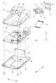
図2〜図4に示すように、車載カメラ1は、筐体2と、光学ユニット12と、第1基板5と、第2基板6と、ケーブル13と、を備える。光学ユニット12、第1基板5、第2基板6及びケーブル13は、筐体2に収容されている。 As shown in FIGS. 2 to 4, the vehicle-mounted camera 1 includes a
図2に示すように、筐体2は、前方側になるほど厚みが小さくなるような形状を有する箱状の部品である。筐体2は、左側壁81、右側壁82、前側壁83、後側壁84、上壁85及び底壁86を備えている。左側壁81及び右側壁82は、左右方向に間隔を隔てて対向配置される。前側壁83及び後側壁84は、左側壁81及び右側壁82の間を連結し、前後に配置される。上壁85及び底壁86は、左側壁81及び右側壁82の間を連結し、上下に配置される。また、筐体2は、左側面61、右側面62、前側面63、後側面64、上面65及び下面66を有する。左側面61は、左側壁81の外表面である。右側面62は、右側壁82の外表面である。前側面63は、前側壁83の外表面である。後側面64は、後側壁84の外表面である。上面65は、上壁85の外表面である。下面66は、底壁86の外表面である。ウインドシールド7の内側に車載カメラ1が設置された状態において、筐体2の上面65はウインドシールド7に対向する。つまり、上壁85はウインドシールド7に対向する筐体2の部分であり、底壁86は上壁85とは反対側に位置する筐体2の部分である。 As shown in FIG. 2, the
図3に示すように、筐体2は、第1ケーシング10及び第2ケーシング11を備える。筐体2は、第1ケーシング10及び第2ケーシング11が互いに対向して接合され一体となっている。第1ケーシング10は、筐体2の上壁85及び側壁81〜84の一部を構成する。第2ケーシング11は、筐体2の底壁86及び側壁81〜84の一部を構成する。つまり、筐体2の上面65は、第1ケーシング10の上面65と一致し、筐体2の下面66は、第2ケーシング11の下面66と一致する。 As shown in FIG. 3, the
第1ケーシング10は、アルミニウムの材料を用いて構成されている。
第1ケーシング10は、上壁85と、左側壁81の一部と、右側壁82の一部と、前側壁83の一部と、後側壁84の一部と、を有する。上壁85は、光学ユニット12及び第1基板5を収納するために、上壁85の後方に、上方に隆起した隆起部20を備える。隆起部20は前方に向けて開口するレンズ孔21を有する。The
The
第1ケーシング10は、光学ユニット12と、第1基板5と、第2基板6と、第2ケーシング11と、が接合される構成である。
第2ケーシング11はアルミニウムの材料を用いて構成されている。The
The
第2ケーシング11は、底壁86と、後側壁84の一部と、前側壁83の一部と、左側壁81の一部と、右側壁82の一部と、を有する。底壁86は、第2ケーシング11の下面66を有する板状部分である。後側壁84は、筐体2がウインドシールド7の内側に設置された状態において、筐体2における車両の後方側に、底壁86から立設して設けられている。 The
光学ユニット12は、鏡筒部8と、ベース部9と、レンズ3と、を備える。鏡筒部8及びベース部9は、樹脂で一体成形されている。
鏡筒部8は、筒状の形状を有し、内部にレンズ3を保持する。レンズ3は、車両の前方からの光を受け入れることが可能なように、レンズ孔21に露出し、光軸が鏡筒部8の中心軸と一致するように、光軸方向に並べられている。The
The
ベース部9は、レンズ3の光軸と垂直な方向に広がり、後方が開放した直方体状の形状を有する。ベース部9は、光学ユニット12を第1ケーシング10に固定するために、左方向及び右方向に延びた取付け部を有する。 The
第1基板5は、イメージャ4と、第1コネクタ14と、が実装された板状部品である。イメージャ4は、矩形板状であり、表面が単一表面をなす受光面で構成されている。また、イメージャ4は、レンズ3を介して得られる光学的な受光面に結像された被写体像を電気的な画像信号に変換する。具体的には、イメージャ4は、CMOSイメージセンサ等の半導体イメージセンサ素子である。第1コネクタ14は、左右方向に長い長方形状であり、イメージャ4が実装される面、つまり第1ケーシング10に覆われる側の面と同一の面における下端に配置されている。また、第1コネクタ14は、後述するケーブル13の端部を差し込んで固定できるように構成されている。 The
第1基板5は、イメージャ4において変換された画像信号をケーブル13を介して電気的に接続される第2基板6に出力する。第1基板5は、イメージャ4及び第1コネクタ14が搭載された面を前方に向けて、ベース部9の後方の開放端部に組み付けられる。第1基板5は光学ユニット12とともに隆起部20に収納される。つまり、第1基板5は、水平面に対して垂直又は垂直に近い向きに、一方の面が第1ケーシング10に覆われる状態で、第1ケーシング10に組み付けられている。また、第1基板5は、第1ケーシング10に覆われない側の面は、第2ケーシング11により覆われている。 The
第2基板6は、イメージャ4によって得られた画像信号や後述する画像処理LSIによって処理された画像信号を記録、あるいは他の装置に伝送する板状部品である。第1ケーシング10及び第2ケーシング11が接合された際に、第2基板6の一方の面が上壁85に対向し、第2基板6の他方の面が底壁86に対向するように配置される。つまり、第2基板6は、水平又は水平に近い向きに、一方の面が第1ケーシング10に覆われる状態で、第1ケーシング10に組み付けられている。また、第2基板6は、第1ケーシング10に覆われない側の面は、第2ケーシング11により覆われている。 The
第2基板6には、画像処理LSI、第2コネクタ15及び第3コネクタ71等が搭載されている。なお、LSIは、Large Scale Integrationの略語である。画像処理LSIは、イメージャ4によって変換された画像信号を処理する。画像処理LSIは、第2基板6の底壁86に対向する面に搭載されている。第2コネクタ15は、長方形状であり、第2基板6の上壁85に対向する面、つまり第1ケーシング10に覆われる側の面の後端における右側に配置されている。また、第2コネクタ15は、第1コネクタ14と同様にケーブル13の端部を差し込んで固定できるように構成されている。第3コネクタ71は、電源の供給及び通信を行うためのものであり、筐体2の後端における左側に配置されている。第3コネクタ71は、車両からの電源を供給するとともに、第2基板6で算出された演算結果を外部へ出力する。なお、画像処理LSIは制御回路に相当する。 An image processing LSI, a
第1基板5と第2基板6とは筐体2内で角度をもって配置されており、第1ケーシング10と第1基板5と第2基板6とにより空間が形成される。ここで、「角度をもって」とは、第1基板5と第2基板6とが互いに異なる角度で配置されることをいう。本実施形態では、第1基板5と第2基板6とは垂直又は垂直に近い角度で配置される。 The
ケーブル13は、第1基板5と第2基板6とを電気的に接続する複数本の導体が幅方向に配列されたフィルム状の部品である。ケーブル13は、図4に示すように、第1基板5及び第2基板6のそれぞれにおける第1ケーシング10に覆われる側の面に固定されるように、一端が第1コネクタ14に装着され、他端が第2コネクタ15に装着される。なお、第1基板5と第2基板6とは、ケーブル13が装着された後に第1ケーシング10に組み付けられる。 The
[2.効果]
以上詳述した実施形態によれば、以下の効果が得られる。
(2a)本実施形態では、第1基板5及び第2基板6のそれぞれは、一方の面が第1ケーシング10に覆われる状態で、第1ケーシング10に組み付けられている。また、第1基板5及び第2基板6における第1ケーシング10に覆われない側の面は、第2ケーシング11により覆われている。そして、ケーブル13は、第1基板5及び第2基板6のそれぞれにおける第1ケーシング10に覆われる側の面に固定されている。換言すれば、ケーブル13は、一定の角度をなすように配置された第1基板5及び第2基板6に対してそれぞれの内側となる面に固定されている。このため、図5に例示するように、第1基板50及び第2基板60に対してそれぞれの外側となる面にケーブル103が固定される構成と比較して、ケーブル13が第2ケーシング11に近接しにくくなる。また、本実施形態では、ケーブル13は、一定の角度をなすように配置された第1基板5及び第2基板6と、第1ケーシング10と、の間に形成される内部空間に収納されやすくなる。このため、ケーブル13は、第1ケーシング10にも近接しにくい。つまり、本実施形態によれば、ケーブル13が筐体2に近接しにくくなる。したがって、車載カメラ1から発せられるノイズを抑制することができる。[2. effect]
According to the embodiment described in detail above, the following effects can be obtained.
(2a) In the present embodiment, each of the
(2b)本実施形態では、ケーブル13は、一定の角度をなすように配置された第1基板5及び第2基板6に対してそれぞれの内側となる面に固定されている。このため、図5に例示するように、第1基板50及び第2基板60に対してそれぞれの外側となる面にケーブル103が固定される構成と比較して、ケーブル13の長さを短くすることができる。これにより、材料費を削減することができる。なお、第1基板及び第2基板を第1ケーシングに組み付けた後に、第1基板及び第2基板にケーブルを固定しようとすると、第1基板及び第2基板における第1ケーシングに覆われない側の面、つまり、それぞれの外側となる面にケーブルを固定する必要があった。これに対し、本実施形態では、第1基板5及び第2基板6にケーブル13が固定された後に、第1基板5及び第2基板6が第1ケーシング10に組み付けられる。このため、本実施形態によれば、第1基板5及び第2基板6における第1ケーシング10に覆われる側の面、つまり、それぞれの内側となる面にケーブル13が固定される構成が実現できる。 (2b) In the present embodiment, the
(2c)本実施形態では、車載カメラ1は、ルームミラーの近傍に取り付けられている。このため、例えばルームミラーの近傍にラジオ等のアンテナが設けられている場合、車載カメラ1から発せられるノイズを抑制することで、アンテナへの悪影響を生じにくくすることができる。 (2c) In the present embodiment, the vehicle-mounted camera 1 is mounted in the vicinity of the rear-view mirror. Therefore, for example, when an antenna such as a radio is provided in the vicinity of the rear-view mirror, it is possible to suppress adverse effects on the antenna by suppressing noise emitted from the vehicle-mounted camera 1.
[3.他の実施形態]
以上、本開示の実施形態について説明したが、本開示は、上記実施形態に限定されることなく、種々変形して実施することができる。[3. Other embodiments]
Although the embodiments of the present disclosure have been described above, the present disclosure is not limited to the above-described embodiments, and can be implemented in various modifications.
(3a)筐体2は、第1ケーシング10及び第2ケーシング11以外の他の構成部品を更に有していてもよい。
(3b)ケーブル13の形状は、フィルム状以外の他の形状であってもよい。(3a) The
(3b) The shape of the
(3c)上記実施形態における1つの構成要素が有する機能を、複数の構成要素によって実現したり、1つの構成要素が有する1つの機能を、複数の構成要素によって実現したりしてもよい。また、複数の構成要素が有する複数の機能を、1つの構成要素によって実現したり、複数の構成要素によって実現される1つの機能を、1つの構成要素によって実現したりしてもよい。また、上記実施形態の構成の一部を省略してもよい。なお、特許請求の範囲に記載した文言のみによって特定される技術思想に含まれるあらゆる態様が本開示の実施形態である。 (3c) The function of one component in the above embodiment may be realized by a plurality of components, or one function of one component may be realized by a plurality of components. Further, a plurality of functions possessed by the plurality of components may be realized by one component, or one function realized by the plurality of components may be realized by one component. Further, a part of the configuration of the above embodiment may be omitted. It should be noted that all aspects included in the technical idea specified only by the wording described in the claims are embodiments of the present disclosure.
1…車載カメラ、2…筐体、3…レンズ、4…イメージャ、5…第1基板、6…第2基板、7…ウインドシールド、10…第1ケーシング、11…第2ケーシング、13…ケーブル。 1 ... In-vehicle camera, 2 ... Housing, 3 ... Lens, 4 ... Imager, 5 ... 1st board, 6 ... 2nd board, 7 ... Windshield, 10 ... 1st casing, 11 ... 2nd casing, 13 ... Cable ..
Claims (1)
Translated fromJapaneseレンズ(3)を介して得られる光学的な像を画像信号に変換するためのイメージャ(4)を有する第1基板(5)と、
前記画像信号を処理する制御回路を有する第2基板(6)と、
前記第1基板と前記第2基板とを電気的に接続するケーブル(13)と、
前記第1基板、前記第2基板及び前記ケーブルを収容する筐体(2)と、
を備え、
前記筐体は、第1ケーシング(10)及び第2ケーシング(11)を有し、
前記第1基板及び前記第2基板のそれぞれは、一方の面が前記第1ケーシングに覆われる状態で、前記第1ケーシングに組み付けられており、
前記第1基板及び前記第2基板における前記第1ケーシングに覆われない側の面は、前記第2ケーシングにより覆われており、
前記ケーブルは、前記第1基板及び前記第2基板のそれぞれにおける前記第1ケーシングに覆われる側の面に固定されており、
前記第1基板は、当該第1基板の前記第1ケーシングに覆われる側の面であって、前記イメージャが実装される面に第1コネクタ(14)を有し、
前記第2基板は、当該第2基板の前記第1ケーシングに覆われる側の面に第2コネクタ(15)を有し、
前記第1基板と前記第2基板とは、前記第1基板の前記第1コネクタを有する面と前記第2基板の前記第2コネクタを有する面とが近接するように、前記筐体内で角度をもって配置され、
前記ケーブルは、一端が前記第1コネクタに装着され、他端が前記第2コネクタに装着される、車載カメラ。An in-vehicle camera (1) installed inside the windshield (7) of the vehicle and capturing the front of the vehicle.
A first substrate (5) having an imager (4) for converting an optical image obtained through a lens (3) into an image signal, and
A second substrate (6) having a control circuit for processing the image signal, and
A cable (13) that electrically connects the first board and the second board,
A housing (2) for accommodating the first substrate, the second substrate, and the cable,
With
The housing has a first casing (10) and a second casing (11).
Each of the first substrate and the second substrate is assembled to the first casing with one surface covered by the first casing.
The surfaces of the first substrate and the second substrate on the side not covered by the first casing are covered by the second casing.
The cable isfixed to the surface of the side to be covered with the first casing in each of the first substrate and the second substrate,
The first substrate is a surface of the first substrate that is covered with the first casing, and has a first connector (14) on the surface on which the imager is mounted.
The second substrate has a second connector (15) on the surface of the second substrate on the side covered by the first casing.
The first substrate and the second substrate are angled in the housing so that the surface of the first substrate having the first connector and the surface of the second substrate having the second connector are close to each other. Placed,
The cable has one end attached to the first connector and the other end Ruis mounted on the second connector, the vehicle-mounted camera.
Priority Applications (4)
| Application Number | Priority Date | Filing Date | Title |
|---|---|---|---|
| JP2017091227AJP6926643B2 (en) | 2017-05-01 | 2017-05-01 | In-vehicle camera |
| US15/960,984US10511752B2 (en) | 2017-05-01 | 2018-04-24 | In-vehicle camera |
| CN201810379333.8ACN108808295B (en) | 2017-05-01 | 2018-04-25 | Vehicle-mounted camera |
| DE102018206678.7ADE102018206678A1 (en) | 2017-05-01 | 2018-04-30 | The in-vehicle camera |
Applications Claiming Priority (1)
| Application Number | Priority Date | Filing Date | Title |
|---|---|---|---|
| JP2017091227AJP6926643B2 (en) | 2017-05-01 | 2017-05-01 | In-vehicle camera |
Publications (2)
| Publication Number | Publication Date |
|---|---|
| JP2018189773A JP2018189773A (en) | 2018-11-29 |
| JP6926643B2true JP6926643B2 (en) | 2021-08-25 |
Family
ID=63895679
Family Applications (1)
| Application Number | Title | Priority Date | Filing Date |
|---|---|---|---|
| JP2017091227AActiveJP6926643B2 (en) | 2017-05-01 | 2017-05-01 | In-vehicle camera |
Country Status (4)
| Country | Link |
|---|---|
| US (1) | US10511752B2 (en) |
| JP (1) | JP6926643B2 (en) |
| CN (1) | CN108808295B (en) |
| DE (1) | DE102018206678A1 (en) |
Families Citing this family (6)
| Publication number | Priority date | Publication date | Assignee | Title |
|---|---|---|---|---|
| US11767012B2 (en)* | 2017-01-19 | 2023-09-26 | Hl Klemove Corp. | Camera system for intelligent driver assistance system, and driver assistance system and method |
| US11433827B2 (en)* | 2019-06-07 | 2022-09-06 | Volvo Car Corporation | Bracket assembly for securing a safety equipment module to a windowpane of a vehicle |
| WO2021028009A1 (en)* | 2019-08-09 | 2021-02-18 | Ficomirrors S.A.U | Camera module for vehicles |
| JP7334675B2 (en)* | 2020-05-25 | 2023-08-29 | 株式会社デンソー | In-vehicle camera and vehicle control system |
| US11851008B2 (en) | 2021-03-15 | 2023-12-26 | Illinois Tool Works Inc. | Camera bracket assembly |
| WO2022197539A1 (en)* | 2021-03-15 | 2022-09-22 | Illinois Tool Works Inc. | Camera bracket assembly |
Family Cites Families (17)
| Publication number | Priority date | Publication date | Assignee | Title |
|---|---|---|---|---|
| JP2003051350A (en) | 2001-08-08 | 2003-02-21 | Auto Network Gijutsu Kenkyusho:Kk | Automotive electronic unit |
| US8339453B2 (en)* | 2010-07-14 | 2012-12-25 | Trw Automotive U.S. Llc | Apparatus for use in association with a vehicle |
| DE102011103302A1 (en)* | 2011-06-03 | 2012-12-06 | Conti Temic Microelectronic Gmbh | Camera system for a vehicle |
| CN103858425B (en)* | 2011-08-02 | 2018-03-30 | 马格纳电子系统公司 | Vehicle camera system |
| US9871971B2 (en)* | 2011-08-02 | 2018-01-16 | Magma Electronics Inc. | Vehicle vision system with light baffling system |
| DE102012200200B4 (en)* | 2012-01-09 | 2020-09-17 | Robert Bosch Gmbh | Camera system, in particular for a vehicle, and a vehicle |
| KR20130109311A (en)* | 2012-03-27 | 2013-10-08 | 주식회사 만도 | Camera module for vehicle |
| US20140192188A1 (en)* | 2012-11-21 | 2014-07-10 | Technology Advancement Group, Inc. | Device and method for enhancing covert operations in hostile environments by reducing bandwidth and power requirements |
| US20150042798A1 (en)* | 2013-08-08 | 2015-02-12 | Honda Elesys Co., Ltd. | In-vehicle camera |
| JP6220754B2 (en)* | 2014-08-26 | 2017-10-25 | 日立オートモティブシステムズ株式会社 | In-vehicle camera |
| CN107409172B (en)* | 2015-04-24 | 2020-05-19 | 日立汽车系统株式会社 | Image pickup apparatus |
| JP6421691B2 (en)* | 2015-04-28 | 2018-11-14 | 株式会社デンソー | Camera device |
| JP6369386B2 (en)* | 2015-04-28 | 2018-08-08 | 株式会社デンソー | Camera device |
| JP6390512B2 (en)* | 2015-05-21 | 2018-09-19 | 株式会社デンソー | In-vehicle camera device |
| JP6519355B2 (en)* | 2015-06-30 | 2019-05-29 | 株式会社デンソー | Camera apparatus and in-vehicle system |
| JP6599470B2 (en)* | 2015-09-14 | 2019-10-30 | 株式会社ヨコオ | In-vehicle antenna device |
| JP2017118445A (en)* | 2015-12-25 | 2017-06-29 | 日本電産エレシス株式会社 | On-vehicle camera |
- 2017
- 2017-05-01JPJP2017091227Apatent/JP6926643B2/enactiveActive
- 2018
- 2018-04-24USUS15/960,984patent/US10511752B2/enactiveActive
- 2018-04-25CNCN201810379333.8Apatent/CN108808295B/enactiveActive
- 2018-04-30DEDE102018206678.7Apatent/DE102018206678A1/enactivePending
Also Published As
| Publication number | Publication date |
|---|---|
| JP2018189773A (en) | 2018-11-29 |
| US10511752B2 (en) | 2019-12-17 |
| CN108808295A (en) | 2018-11-13 |
| CN108808295B (en) | 2021-02-26 |
| DE102018206678A1 (en) | 2018-11-08 |
| US20180316833A1 (en) | 2018-11-01 |
Similar Documents
| Publication | Publication Date | Title |
|---|---|---|
| JP6926643B2 (en) | In-vehicle camera | |
| US11678038B2 (en) | Parts for imaging apparatus and imaging apparatus | |
| KR101724300B1 (en) | Stereo camera | |
| US10506145B2 (en) | Camera apparatus and camera module | |
| JP2007022364A (en) | Car camera | |
| US10848649B2 (en) | Imaging device having heat radiation structure | |
| CN108116331B (en) | imaging device | |
| KR102566959B1 (en) | Radar apparatus | |
| JP6415649B1 (en) | Car camera | |
| CN104954641A (en) | Camera module | |
| JP2015170516A (en) | connector | |
| CN105467391A (en) | Radar apparatus | |
| WO2018116599A1 (en) | Electronic device | |
| JP7050463B2 (en) | Electronic control device | |
| US10609261B2 (en) | Optical camera to be mounted on vehicles | |
| JP2022123744A (en) | imaging unit | |
| JP2018069878A (en) | On-vehicle camera device | |
| JP2017173772A (en) | Electronic component mounting member, image pickup device, and on-vehicle image pickup device | |
| KR102620516B1 (en) | Camera module for vehicle | |
| JP2008263340A (en) | Imaging system |
Legal Events
| Date | Code | Title | Description |
|---|---|---|---|
| A621 | Written request for application examination | Free format text:JAPANESE INTERMEDIATE CODE: A621 Effective date:20200415 | |
| A977 | Report on retrieval | Free format text:JAPANESE INTERMEDIATE CODE: A971007 Effective date:20210127 | |
| A131 | Notification of reasons for refusal | Free format text:JAPANESE INTERMEDIATE CODE: A131 Effective date:20210302 | |
| A521 | Request for written amendment filed | Free format text:JAPANESE INTERMEDIATE CODE: A523 Effective date:20210426 | |
| TRDD | Decision of grant or rejection written | ||
| A01 | Written decision to grant a patent or to grant a registration (utility model) | Free format text:JAPANESE INTERMEDIATE CODE: A01 Effective date:20210706 | |
| A61 | First payment of annual fees (during grant procedure) | Free format text:JAPANESE INTERMEDIATE CODE: A61 Effective date:20210719 | |
| R151 | Written notification of patent or utility model registration | Ref document number:6926643 Country of ref document:JP Free format text:JAPANESE INTERMEDIATE CODE: R151 | |
| R250 | Receipt of annual fees | Free format text:JAPANESE INTERMEDIATE CODE: R250 | |
| R250 | Receipt of annual fees | Free format text:JAPANESE INTERMEDIATE CODE: R250 |