JP6926076B2 - Multi-layer surgical stapler buttress assembly - Google Patents
Multi-layer surgical stapler buttress assemblyDownload PDFInfo
- Publication number
- JP6926076B2 JP6926076B2JP2018522073AJP2018522073AJP6926076B2JP 6926076 B2JP6926076 B2JP 6926076B2JP 2018522073 AJP2018522073 AJP 2018522073AJP 2018522073 AJP2018522073 AJP 2018522073AJP 6926076 B2JP6926076 B2JP 6926076B2
- Authority
- JP
- Japan
- Prior art keywords
- adhesive layer
- end effector
- buttress
- anvil
- adhesive
- Prior art date
- Legal status (The legal status is an assumption and is not a legal conclusion. Google has not performed a legal analysis and makes no representation as to the accuracy of the status listed.)
- Active
Links
Images


Classifications
- A—HUMAN NECESSITIES
- A61—MEDICAL OR VETERINARY SCIENCE; HYGIENE
- A61B—DIAGNOSIS; SURGERY; IDENTIFICATION
- A61B17/00—Surgical instruments, devices or methods
- A61B17/10—Surgical instruments, devices or methods for applying or removing wound clamps, e.g. containing only one clamp or staple; Wound clamp magazines
- A61B17/105—Wound clamp magazines
- A—HUMAN NECESSITIES
- A61—MEDICAL OR VETERINARY SCIENCE; HYGIENE
- A61B—DIAGNOSIS; SURGERY; IDENTIFICATION
- A61B17/00—Surgical instruments, devices or methods
- A61B17/068—Surgical staplers, e.g. containing multiple staples or clamps
- A61B17/072—Surgical staplers, e.g. containing multiple staples or clamps for applying a row of staples in a single action, e.g. the staples being applied simultaneously
- A61B17/07292—Reinforcements for staple line, e.g. pledgets
- A—HUMAN NECESSITIES
- A61—MEDICAL OR VETERINARY SCIENCE; HYGIENE
- A61B—DIAGNOSIS; SURGERY; IDENTIFICATION
- A61B17/00—Surgical instruments, devices or methods
- A61B17/068—Surgical staplers, e.g. containing multiple staples or clamps
- A—HUMAN NECESSITIES
- A61—MEDICAL OR VETERINARY SCIENCE; HYGIENE
- A61B—DIAGNOSIS; SURGERY; IDENTIFICATION
- A61B17/00—Surgical instruments, devices or methods
- A61B17/068—Surgical staplers, e.g. containing multiple staples or clamps
- A61B17/072—Surgical staplers, e.g. containing multiple staples or clamps for applying a row of staples in a single action, e.g. the staples being applied simultaneously
- A61B17/07207—Surgical staplers, e.g. containing multiple staples or clamps for applying a row of staples in a single action, e.g. the staples being applied simultaneously the staples being applied sequentially
- A—HUMAN NECESSITIES
- A61—MEDICAL OR VETERINARY SCIENCE; HYGIENE
- A61B—DIAGNOSIS; SURGERY; IDENTIFICATION
- A61B17/00—Surgical instruments, devices or methods
- A61B2017/00004—(bio)absorbable, (bio)resorbable or resorptive
- A—HUMAN NECESSITIES
- A61—MEDICAL OR VETERINARY SCIENCE; HYGIENE
- A61B—DIAGNOSIS; SURGERY; IDENTIFICATION
- A61B17/00—Surgical instruments, devices or methods
- A61B2017/00367—Details of actuation of instruments, e.g. relations between pushing buttons, or the like, and activation of the tool, working tip, or the like
- A61B2017/00398—Details of actuation of instruments, e.g. relations between pushing buttons, or the like, and activation of the tool, working tip, or the like using powered actuators, e.g. stepper motors, solenoids
- A—HUMAN NECESSITIES
- A61—MEDICAL OR VETERINARY SCIENCE; HYGIENE
- A61B—DIAGNOSIS; SURGERY; IDENTIFICATION
- A61B17/00—Surgical instruments, devices or methods
- A61B2017/00526—Methods of manufacturing
- A—HUMAN NECESSITIES
- A61—MEDICAL OR VETERINARY SCIENCE; HYGIENE
- A61B—DIAGNOSIS; SURGERY; IDENTIFICATION
- A61B17/00—Surgical instruments, devices or methods
- A61B2017/00831—Material properties
- A61B2017/00951—Material properties adhesive
Landscapes
- Health & Medical Sciences (AREA)
- Life Sciences & Earth Sciences (AREA)
- Surgery (AREA)
- Heart & Thoracic Surgery (AREA)
- Engineering & Computer Science (AREA)
- Biomedical Technology (AREA)
- Nuclear Medicine, Radiotherapy & Molecular Imaging (AREA)
- Medical Informatics (AREA)
- Molecular Biology (AREA)
- Animal Behavior & Ethology (AREA)
- General Health & Medical Sciences (AREA)
- Public Health (AREA)
- Veterinary Medicine (AREA)
- Surgical Instruments (AREA)
- Materials For Medical Uses (AREA)
Description
Translated fromJapanese切開創をより小さくすることで、術後の回復時間及び合併症を低減させ得ることから、一部の状況では、従来の開腹外科用装置よりも内視鏡外科用器具が好ましい場合がある。このため、内視鏡外科用器具の中には、トロカールのカニューレを通して所望の手術部位に遠位エンドエフェクタを配置するのに好適なものがある。これらの遠位エンドエフェクタは、様々な形で組織と係合して診断又は治療効果を得ることができる(例えば、エンドカッター、把持具、カッター、ステープラ、クリップアプライヤ、アクセス装置、薬物/遺伝子治療送達装置、及び、超音波振動、RF、レーザなどを使用するエネルギー送達装置など)。内視鏡外科用器具は、エンドエフェクタとハンドル部分との間に、臨床医によって操作されるシャフトを含むことがある。かかるシャフトは、所望の深さへの挿入及びシャフトの長手方向軸を中心とした回転を可能にし、それにより患者の体内でエンドエフェクタの位置決めを行うことを容易とする。エンドエフェクタの位置決めは、エンドエフェクタをシャフトの長手方向軸に対して選択的に関節動作させるか又は別の形で撓ませることを可能にする、1つ又は2つ以上の関節ジョイント又は機構を含めることによって更に容易に行うことができる。 In some situations, endoscopic surgical instruments may be preferred over conventional open surgical devices, as smaller incisions can reduce postoperative recovery time and complications. For this reason, some endoscopic surgical instruments are suitable for placing the distal end effector at the desired surgical site through the trocar cannula. These distal end effectors can engage with tissue in various ways to obtain diagnostic or therapeutic effects (eg, end cutters, grippers, cutters, staplers, clip appliers, access devices, drugs / genes). Treatment delivery equipment and energy delivery equipment using ultrasonic vibration, RF, laser, etc.). Endoscopic surgical instruments may include a shaft operated by a clinician between the end effector and the handle portion. Such a shaft allows insertion to a desired depth and rotation about the longitudinal axis of the shaft, thereby facilitating positioning of the end effector within the patient's body. Positioning of the end effector includes one or more joint joints or mechanisms that allow the end effector to selectively joint or otherwise flex with respect to the longitudinal axis of the shaft. This can be done more easily.
内視鏡外科用器具の例として、外科用ステープラが挙げられる。かかるステープラのいくつかは、組織層をクランプし、クランプされた組織層を切断し、組織層を通してステープルを打ち込むことによって、組織層の切断された端部の近くで、切断された組織層同士を互いに実質的にシールするように動作可能である。あくまで例示の外科用ステープラが、1989年2月21日に発行された米国特許第4,805,823号、名称「Pocket Configuration for Internal Organ Staplers」、1995年5月16日に発行された米国特許第5,415,334号、名称「Surgical Stapler and Staple Cartridge」、1995年11月14日に発行された米国特許第5,465,895号、名称「Surgical Stapler Instrument」、1997年1月28日に発行された米国特許第5,597,107号、名称「Surgical Stapler Instrument」、1997年5月27日に発行された米国特許第5,632,432号、名称「Surgical Instrument」、1997年10月7日に発行された米国特許第5,673,840号、名称「Surgical Instrument」、1998年1月6日に発行された米国特許第5,704,534号、名称「Articulation Assembly for Surgical Instruments」、1998年9月29日に発行された米国特許第5,814,055号、名称「Surgical Clamping Mechanism」、2005年12月27日に発行された米国特許第6,978,921号、名称「Surgical Stapling Instrument Incorporating an E−Beam Firing Mechanism」、2006年2月21日に発行された米国特許第7,000,818号、名称「Surgical Stapling Instrument Having Separate Distinct Closing and Firing Systems」、2006年12月5日に発行された米国特許第7,143,923号、名称「Surgical Stapling Instrument Having a Firing Lockout for an Unclosed Anvil」、2007年12月4日に発行された米国特許第7,303,108号、名称「Surgical Stapling Instrument Incorporating a Multi−Stroke Firing Mechanism with a Flexible Rack」、2008年5月6日に発行された米国特許第7,367,485号、名称「Surgical Stapling Instrument Incorporating a Multistroke Firing Mechanism Having a Rotary Transmission」、2008年6月3日に発行された米国特許第7,380,695号、名称「Surgical Stapling Instrument Having a Single Lockout Mechanism for Prevention of Firing」、2008年6月3日に発行された米国特許第7,380,696号、名称「Articulating Surgical Stapling Instrument Incorporating a Two−Piece E−Beam Firing Mechanism」、2008年7月29日に発行された米国特許第7,404,508号、名称「Surgical Stapling and Cutting Device」、2008年10月14日に発行された米国特許第7,434,715号、名称「Surgical Stapling Instrument Having Multistroke Firing with Opening Lockout」、2010年5月25日に発行された米国特許第7,721,930号、名称「Disposable Cartridge with Adhesive for Use with a Stapling Device」、2013年4月2日に発行された米国特許第8,408,439号、名称「Surgical Stapling Instrument with An Articulatable End Effector」、及び2013年6月4日に発行された米国特許第8,453,914号、名称「Motor−Driven Surgical Cutting Instrument with Electric Actuator Directional Control Assembly」に開示されている。上に引用した米国特許のそれぞれの開示内容は、参照により本明細書に組み込まれる。 An example of an endoscopic surgical instrument is a surgical stapler. Some of these staplers clamp the cut tissue layers, cut the clamped tissue layers, and drive staples through the tissue layers so that the cut tissue layers are brought together near the cut ends of the tissue layer. It can operate to substantially seal each other. An exemplary surgical stapler is US Patent No. 4,805,823 issued on February 21, 1989, named "Pocket Configuration for International Orange Staples", US Patent issued on May 16, 1995. No. 5,415,334, name "Surgical Staple and Staple Cartridge", US Pat. No. 5,465,895 issued on November 14, 1995, name "Surgical Stapler Instrument", January 28, 1997. US Pat. No. 5,597,107 issued to US Pat. No. 5,597,107, name "Surgical Standard Instrument", US Pat. US Pat. No. 5,673,840, issued on March 7, 1998, entitled "Surgical Instrument", US Pat. No. 5,704,534, issued on January 6, 1998, named "Artification Assessment for Surgical Instruments". , US Pat. No. 5,814,055 issued on September 29, 1998, name "Surgical Clamping Mechanism", US Pat. No. 6,978,921 issued on December 27, 2005, name. "Surgical Stapling Instrument Incorporating an E-Beam Filling Mechanism", US Patent No. 7,000,818 issued on February 21, 2006, named "Surgical Stapling InstrumentStorment US Pat. No. 7,143,923 issued on May 5, 2007, named "Surgical Stapping Instrument Having a Filling Lockout for an Unclosed Anvil," US Pat. No. 7,303,108 issued on December 4, 2007. Issue, name "Surgical Patenting" Instrument Incorporating a Multi-Stroke Firing Mechanism with a Flexible Rack ", US Patent No. 7,367,485, issued May 6, 2008, entitled" Surgical Stapling Instrument Incorporating a Multistroke Firing Mechanism Having a Rotary Transmission ", U.S. Patent No. 7,380,695 issued on June 3, 2008, named "Surgical Stapleing Instrument Having a Single Lockout Mechanism for Presentation of Firing", U.S. Patent No. 7 issued on June 3, 2008. , 380, 696, name "Artificating Surgical Stapleing Instrument Incorporating a Two-Piece E-Bear Firing Technology", US Pat. No. 7,404,508 issued on July 29, 2008. "Device", US Patent No. 7,434,715 issued on October 14, 2008, name "Surgical Standing Instrument Having Multistroke With Opening Lockout", US Patent No. 7 issued on May 25, 2010. , 721, 930, name "Disposable Cartridge with Advanced for Use with a Stamping Device", US Pat. No. 8,408,439 issued on April 2, 2013, name "Surgical Automatic Art" , And US Pat. No. 8,453,914 issued on June 4, 2013, entitled "Motor-Driven Surgical Cutting Instrument". It is disclosed in "t with Electrical Actuator Directional Control Assembly". The disclosures of each of the US patents cited above are incorporated herein by reference.
上述した外科用ステープラは、内視鏡手術において使用されるものとして記載されているが、このような外科用ステープラは、開口処置及び/又は他の非内視鏡手術でも使用することができることを理解されたい。ほんの一例として、トロカールをステープラの導管として使用しない胸部外科手術では、外科用ステープラを開胸術によって患者の肋骨の間に挿入し、1つ又は2つ以上の臓器に到達させることもできる。かかる手術では、肺につながる血管を切断及び閉鎖するためにステープラが使用される場合もある。例えば、臓器につながる血管を、胸腔から臓器を切除するのに先立ってステープラによって切断して閉鎖することができる。当然のことながら、外科用ステープラを他の様々な状況及び手術で使用することができる。 Although the surgical staplers described above are described as being used in endoscopic surgery, such surgical staplers can also be used in open procedures and / or other non-endoscopic surgery. I want to be understood. As just one example, in chest surgery where the trocar is not used as a conduit for the stapler, a surgical stapler can also be inserted between the patient's ribs by thoracotomy to reach one or more organs. In such surgery, staplers may be used to cut and close the blood vessels that connect to the lungs. For example, blood vessels leading to an organ can be cut and closed with a stapler prior to excision of the organ from the thoracic cavity. Not surprisingly, surgical staplers can be used in a variety of other situations and in surgery.
開胸術を通した使用に特に好適となり得る外科用ステープラの例が、2014年8月28日に公開された米国特許公開第2014/0243801号、名称「Surgical Instrument End Effector Articulation Drive with Pinion and Opposing Racks」、2014年8月28日に公開された米国特許公開第2014/0239041号、名称「Lockout Feature for Movable Cutting Member of Surgical Instrument」、2014年8月28日に公開された米国特許公開第2014/0239042号、名称「Integrated Tissue Positioning and Jaw Alignment Features for Surgical Stapler」、2014年8月28日に公開された米国特許公開第2014/0239036号、名称「Jaw Closure Feature for End Effector of Surgical Instrument」、2014年8月28日に公開された米国特許公開第2014/0239040号、名称「Surgical Instrument with Articulation Lock having a Detenting Binary Spring」、2014年8月28日に公開された米国特許公開第2014/0239043号、名称「Distal Tip Features for End Effector of Surgical Instrument」、2014年8月28日に公開された米国特許公開第2014/0239037号、名称「Staple Forming Features for Surgical Stapling Instrument」、2014年8月28日に公開された米国特許公開第2014/0239038号、名称「Surgical Instrument with Multi−Diameter Shaft」、及び2014年8月28日に公開された米国特許公開第2014/0239044号、名称「Installation Features for Surgical Instrument End Effector Cartridge」に開示されている。上に引用した米国特許公開のそれぞれの開示内容は、参照により本明細書に組み込まれる。 An example of a surgical stapler that may be particularly suitable for use through thoracic surgery is US Patent Publication No. 2014/0243801, published August 28, 2014, entitled "Surgical Instrument End Effect Artist Artification Drive with Pinion and Opposing". Racks ”, US Patent Publication No. 2014/0239041 published on August 28, 2014, name“ Lockout Feature for Mobile Cutting Member of Surgical Instrument ”, US Patent Publication No. 2014 published on August 28, 2014 / 0239042, named "Integrated Tissue Positioning and Jaw Element Features for Surgical Stapler", US Patent Publication No. 2014/0239036 published on August 28, 2014, named "Jow Color US Patent Publication No. 2014/0239040 published on August 28, 2014, named "Surgical Instrument with Articulation Lock having a Detenting Binary Spring", US Patent Publication No. 2014/023403 published on August 28, 2014. No., name "Distal Tip Features for End Effector of Surgical Instrument", US Patent Publication No. 2014/0239037 published on August 28, 2014, name "Standard Forming Features for 14 Year, 2014" US Patent Publication No. 2014/0239038 published on Sunday, named "Surgical Instrument with Multi-Diameter Shaft", and US Patent Publication No. 2014/0239044 published on August 28, 2014, named "Installatio". n Features for Surgical Instrument End Effector Cartridge ”. The respective disclosures of the US patent publications cited above are incorporated herein by reference.
更なる外科用ステープル留め器具が、2014年8月12日に発行された米国特許第8,801,735号、名称「Surgical Circular Stapler with Tissue Retention Arrangements」、2012年3月27日に発行された米国特許第8,141,762号、名称「Surgical Stapler Comprising a Staple Pocket」、2013年2月12日に発行された米国特許第8,371,491号、名称「Surgical End Effector Having Buttress Retention Features」、2014年9月18日に公開された米国特許公開第2014/0263563号、名称「Method and Apparatus for Sealing End−to−End Anastomosis」、2014年9月4日に公開された米国特許公開第2014/0246473号、名称「Rotary Powered Surgical Instruments with Multiple Degrees of Freedom」、2013年8月15日に公開された米国特許公開第2013/0206813号、名称「Linear Stapler」、2008年7月17日に公開された米国特許公開第2008/0169328号、名称「Buttress Material for Use with a Surgical Stapler」、2014年6月10日に出願された米国特許出願第14/300,804号、名称「Woven and Fibrous Materials for Reinforcing a Staple Line」、米国特許出願第14/300,811号、名称「Devices and Methods for Sealing Staples in Tissue」、及び、2014年9月26日に出願された米国特許出願第14/498,070号、名称「Radically Expandable Staple Line」に開示されている。上に引用した米国特許、米国特許公開、米国特許出願のそれぞれの開示内容は、参照により本明細書に組み込まれる。 An additional surgical staple fastening device was issued on March 27, 2012, US Pat. No. 8,801,735, issued August 12, 2014, entitled "Surgical Circular Staple with Tissue Retension Arrangements". U.S. Pat. , US Patent Publication No. 2014/0263563 published on September 18, 2014, name "Method and Apparatus for Sealing End-to-End Anastomosis", US Patent Publication No. 2014 published on September 4, 2014. / 0246473, name "Rotary Powered Surgical Instruments with Multiple Degrees of Freedom", US Patent Publication No. 2013/0286813 published on August 15, 2013, name "Linear Standard" published on August 15, 2013, 2008 US Patent Publication No. 2008/0169328, named "Buttress Material for Use with a Surgical Stapler", US Patent Application No. 14 / 300,804 filed on June 10, 2014, named "Woven and Fibers "For Reinforcing a Standard Line", US Patent Application No. 14 / 300,811, named "Devices and Methods for Sealing Staples in Tissue", and US Patent Application No. 14/498 filed on September 26, 2014. No. 070, the name "Radically Expandable Standard Line" is disclosed. The disclosures of US patents, US patent publications, and US patent applications cited above are incorporated herein by reference.
場合によっては、ステープルによってもたらされる組織の機械的締結を補強するため、外科用ステープル留め器具に支持材料を備えることが望ましい場合がある。かかるバットレスは、適用したステープルが組織から引き抜かれるのを防ぐことができ、ステープルの適用部位又はその付近の組織が裂けるリスクを別の方法で低減することができる。 In some cases, it may be desirable to provide a supporting material in the surgical staple fastening device to reinforce the mechanical fastening of the tissue provided by the staples. Such a buttress can prevent the applied staple from being pulled out of the tissue and can otherwise reduce the risk of tearing of the tissue at or near the application site of the staple.
様々な種類の外科用ステープル留め器具及び関連構成要素が作製され使用されてきたが、本発明者(ら)以前には、添付の請求項に記載されている発明を誰も作製又は使用したことがないものと考えられる。 Various types of surgical staple fasteners and related components have been made and used, but prior to the present inventors, no one has made or used the invention described in the appended claims. It is considered that there is no such thing.
本明細書に組み込まれると共にその一部をなす添付の図面は、本発明の実施形態を示すものであり、上記の本発明の一般的説明、及び以下の実施形態の詳細な説明と共に、本発明の原理を説明する役割を果たすものである。
図面は、いかなる方式でも限定することを意図しておらず、本発明の種々の実施形態は、図面に必ずしも描写されていないものを含め、他の様々な方式で実施し得ることが考えられる。本明細書に組み込まれ、その一部をなす添付図面は、本発明のいくつかの態様を図示したものであり、本説明文と共に本発明の原理を説明する役割を果たすものである。しかしながら、本発明が示される正確な配置に限定されない点が理解される。 The drawings are not intended to be limited in any manner, and it is conceivable that various embodiments of the invention may be implemented in a variety of other ways, including those not necessarily depicted in the drawings. The accompanying drawings, incorporated herein by reference and in part thereof, illustrate some aspects of the invention and serve to explain the principles of the invention along with this description. However, it is understood that the present invention is not limited to the exact arrangement shown.
本発明の特定の例の以下の説明文は、本発明の範囲を限定する目的で用いられるべきではない。本発明の他の例、特徴、態様、実施形態、及び利点は、本発明を実施するために想到される最良の形態の1つを実例として示す以下の説明文より当業者には明らかとなろう。理解されるように、本発明には、いずれも本発明から逸脱することなく、他の異なる、かつ明白な態様が可能である。したがって、図面及び説明は、限定的な性質のものではなく、例示的な性質のものとみなされるべきである。 The following description of a particular example of the invention should not be used to limit the scope of the invention. Other examples, features, embodiments, embodiments, and advantages of the present invention will be apparent to those skilled in the art from the following description exemplifying one of the best embodiments conceivable for carrying out the present invention. Let's do it. As will be appreciated, any other different and obvious aspect of the present invention is possible without departing from the present invention. Therefore, drawings and descriptions should be considered of exemplary nature, not of limited nature.
I.例示的な外科用ステープラ
図1は、例示的な外科用ステープル留め及び切断器具(10)を表し、この器具は、ハンドル組立体(20)と、シャフト組立体(30)と、エンドエフェクタ(40)と、を含む。エンドエフェクタ(40)及びシャフト組立体(30)の遠位部分は、外科的処置を行うために、図1に描写されるような非関節動作状態で、トロカールカニューレを通って患者内の手術部位まで挿入するように寸法決めされている。単なる例示として、患者の腹部内に、患者の2本の肋骨の間に、又はその他の部位に、かかるトロカールを挿入してもよい。一部の状況では、器具(10)は、トロカールなしで使用される。例えば、エンドエフェクタ(40)及びシャフト組立体の遠位部分(30)を、開胸術又は他の種類の切開によって直接挿入することができる。本明細書では、「近位」及び「遠位」といった用語は、器具(10)のハンドル組立体(20)を握っている臨床医を基準として使用されていることを理解されたい。したがって、エンドエフェクタ(40)は、より近位にあるハンドル組立体(20)に対して遠位にある。便宜上、また説明を明確にするため、本明細書では「垂直」及び「水平」といった空間的用語が、図面に対して使用されている点も更に認識されるであろう。しかしながら、外科器具は、多くの配向及び位置で使用されるものであり、これらの用語は、限定的かつ絶対的なものであることを意図するものではない。I. An exemplary surgical stapler FIG. 1 represents an exemplary surgical stapler and cutting instrument (10), which includes a handle assembly (20), a shaft assembly (30), and an end effector (40). ) And, including. The distal portion of the end effector (40) and shaft assembly (30) passes through the trocar cannula to the surgical site within the patient in a non-joint motion state as depicted in FIG. 1 for surgical procedures. It is sized to be inserted up to. As a mere illustration, such a trocar may be inserted within the patient's abdomen, between the patient's two ribs, or elsewhere. In some situations, instrument (10) is used without a trocar. For example, the end effector (40) and the distal portion (30) of the shaft assembly can be inserted directly by thoracotomy or other type of incision. It should be understood that the terms "proximal" and "distal" are used herein with reference to the clinician holding the handle assembly (20) of the instrument (10). Therefore, the end effector (40) is distal to the more proximal handle assembly (20). It will also be appreciated that spatial terms such as "vertical" and "horizontal" are used in the drawings for convenience and for clarity. However, surgical instruments are used in many orientations and positions, and these terms are not intended to be limited and absolute.
A.例示的なハンドル組立体及びシャフト組立体
図1に示すように、本例のハンドル組立体(20)は、ピストルグリップ(22)と、閉鎖トリガー(24と)、発射トリガー(26)とを含む。各トリガー(24、26)は、以下により詳細に記載されるように、ピストル把持部(22)に向かって、かつそれから離れるように選択的に枢動可能である。ハンドル組立体(20)は、取り外し式バッテリーパック(28)を更に含む。これらの構成要素についても、以下でより詳細に説明する。勿論、ハンドル組立体(20)は、上記したもののいずれかに加えて又はその代わりに様々な他の構成要素、特徴、及び動作性を有することができる。ハンドル組立体(20)の他の好適な構成は、本明細書の教示を考慮することで当業者には明らかであろう。A. Illustrative Handle Assembly and Shaft Assembly As shown in FIG. 1, the handle assembly (20) of this example includes a pistol grip (22), a closing trigger (24), and a firing trigger (26). .. Each trigger (24, 26) is selectively pivotable towards and away from the pistol grip (22), as described in more detail below. The handle assembly (20) further includes a removable battery pack (28). These components will also be described in more detail below. Of course, the handle assembly (20) can have various other components, features, and operability in addition to or in place of any of the above. Other suitable configurations of the handle assembly (20) will be apparent to those skilled in the art by considering the teachings herein.
図1〜2に示すように、本例のシャフト組立体(30)は、外側閉鎖管(32)と、関節運動部(34と)、閉鎖用リング(36)とを含み、閉鎖用リングは更にエンドエフェクタ(40)に結合される。閉鎖チューブ(32)はシャフト組立体(30)の長さに沿って延在する。閉鎖リング(36)は、関節運動部(34)の遠位に位置付けられている。閉鎖管(32)及び閉鎖用リング(36)は、ハンドル組立体(20)に対して長手方向に並進するように構成されている。閉鎖チューブ(32)の長手方向並進運動は、関節運動部(34)を介して閉鎖リング(36)に伝達される。閉鎖管(32)及び閉鎖用リング(36)を長手方向に並進するのに使用できる例示の機構は、以下により詳細に記載される。 As shown in FIGS. 1 and 2, the shaft assembly (30) of this example includes an outer closing tube (32), a range of motion (34), and a closing ring (36). It is further coupled to the end effector (40). The closing tube (32) extends along the length of the shaft assembly (30). The closure ring (36) is located distal to the range of motion (34). The closing tube (32) and closing ring (36) are configured to translate longitudinally with respect to the handle assembly (20). The longitudinal translational motion of the closure tube (32) is transmitted to the closure ring (36) via the range of motion (34). Illustrative mechanisms that can be used to translate the closure tube (32) and closure ring (36) longitudinally are described in more detail below.
関節運動部(34)は、シャフト組立体(30)の長手方向軸(LA)から所望の角度(α)で横方向へ離れるように、閉鎖リング(36)とエンドエフェクタ(40)を横方向に偏向させるよう動作可能である。本例では、関節運動は、シャフト組立体(30)の近位端に位置する関節運動制御ノブ(35)によって制御される。閉鎖用リング(36)及びエンドエフェクタ(40)は、ノブ(35)の回転に反応してシャフト組立体(30)の長手方向軸(LA)に垂直な軸の周りを枢動する。関節運動部(34)は、関節運動部(34)が真っ直ぐな構成であるか、又は関節運動構成であるかにかかわらず、閉鎖管(32)が閉鎖用リング(36)まで長手方向に並進するのを伝達するように構成されている。単なる例として、関節運動部(34)及び/又は関節運動制御ノブ(35)が、2014年8月28日に公開された米国特許公開第2014/0243801号、名称「Surgical Instrument End Effector Articulation Drive with Pinion and Opposing Racks」(その開示内容は参照によって本明細書に組み込まれる)、及び/若しくは、2014年6月25日に出願された米国特許出願第14/314,125号、名称「Articulation Drive Features for Surgical Stapler」(その開示内容は参照によって本明細書に組み込まれる)のうちの少なくとも一部に従って、かつ/又は、以下の様々な教示に従って構成され動作可能となり得る。関節運動部(34)及び関節動作ノブ(35)が採り得る他の好適な形態は、本明細書の教示を鑑みれば当業者には明らかになるであろう。 The range of motion (34) laterally displaces the closure ring (36) and end effector (40) so that it laterally separates from the longitudinal axis (LA) of the shaft assembly (30) at a desired angle (α). It can be operated to deflect to. In this example, the joint movement is controlled by a joint movement control knob (35) located at the proximal end of the shaft assembly (30). The closing ring (36) and end effector (40) pivot around an axis perpendicular to the longitudinal axis (LA) of the shaft assembly (30) in response to rotation of the knob (35). The range of motion (34) is such that the closing tube (32) translates longitudinally to the closing ring (36) regardless of whether the range of motion (34) is straight or has a range of motion. It is configured to convey what to do. As a mere example, the joint movement part (34) and / or the joint movement control knob (35) is published in US Patent Publication No. 2014/0243801, entitled "Surgical Instrument End Effector Articulation Drive with", published on August 28, 2014. "Pinion and Opposing Racks" (whose disclosure is incorporated herein by reference) and / or US Patent Application No. 14 / 314,125, filed June 25, 2014, entitled "Artification Drive Joints". It may be configured and operational according to at least a portion of the "for Surgical Stapler" (whose disclosure is incorporated herein by reference) and / or according to the various teachings below. Other suitable forms that the range of motion (34) and the joint motion knob (35) can take will be apparent to those skilled in the art in light of the teachings herein.
図1に示すように、本例のシャフト組立体(30)は、回転ノブ(31)を更に含む。回転ノブ(31)は、シャフト組立体(30)の長手方向軸(LA)の周りを、ハンドル組立体(20)に対して、全シャフト組立体(30)及びエンドエフェクタ(40)を回転するように動作可能である。当然のことながら、シャフト組立体(30)は、上記したもののいずれかに加えて又はその代わりに様々な他の構成要素、特徴、及び動作性を有することができる。単に例として、シャフト組立体(30)の少なくとも部分は、2014年8月28日に公開された米国特許公開第2014/0239038号、名称「Surgical Instrument with Multi−Diameter Shaft」の教示のうちの少なくともいくつかに従って構成されてもよい。シャフト組立体(30)の他の好適な構成は、本明細書の教示を鑑みれば当業者には明らかになるであろう。 As shown in FIG. 1, the shaft assembly (30) of this example further includes a rotary knob (31). The rotary knob (31) rotates the entire shaft assembly (30) and end effector (40) around the longitudinal axis (LA) of the shaft assembly (30) with respect to the handle assembly (20). It is possible to operate like this. Of course, the shaft assembly (30) can have various other components, features, and operability in addition to or in place of any of the above. By way of example only, at least a portion of the shaft assembly (30) is at least in the teaching of US Patent Publication No. 2014/0239038, entitled "Surgical Instrument with Multi-Diameter Shaft", published August 28, 2014. It may be configured according to some. Other suitable configurations of the shaft assembly (30) will be apparent to those skilled in the art in light of the teachings herein.
B.例示的なエンドエフェクタ
図1〜3にも示されているように、本例のエンドエフェクタ(40)は、下側ジョー(50)及び枢動可能なアンビル(60)を含む。アンビル(60)は、下側ジョー(50)の対応する湾曲スロット(54)に配置されている一対の一体的な、外側に延在するピン(66)を含む。アンビル(60)は、開放位置(図2に示す)と閉鎖位置(図1に示す)との間で、下側ジョー(50)に向かって、また下側ジョー(50)から離れるように枢動可能である。「枢動可能」という用語(及び「枢動」を基体とした類義語)の使用は、必ずしも固定軸を中心とした枢動運動を必要とすると理解されるべきではない。例えば、本例において、アンビル(60)は、ピン(66)により画定される軸を中心に枢動し、このピンは、アンビル(60)が下側ジョー(50)に向かって動くと、下側ジョー(50)の湾曲スロット(54)に沿って摺動する。かかる形態では、枢動軸がスロット(54)によって画定された経路に沿って並進する一方で、アンビル(60)はその軸を中心として同時に枢動する。追加的に又は代替的に、まず枢動軸がスロット(54)に沿って摺動し、次いで枢動軸がスロット(54)に沿ってある一定の距離を摺動した後に、アンビル(60)が枢動軸を中心として枢動してもよい。そのような摺動/並進枢動運動は、「枢動」、「枢動する」「枢動の」、「枢動可能な」、「枢動している」などの用語内に包含されることを理解されたい。当然のことながら、一部の形態は、固定されたままである、かつスロット又はチャネルなどの内側を並進しない、軸を中心としたアンビル(60)の枢動運動を提供してもよい。B. Illustrative End Effectors As also shown in FIGS. 1-3, the end effectors (40) of this example include a lower jaw (50) and a pivotable anvil (60). The anvil (60) includes a pair of integral, outwardly extending pins (66) located in the corresponding curved slots (54) of the lower jaw (50). The anvil (60) is pivoted between the open position (shown in FIG. 2) and the closed position (shown in FIG. 1) toward the lower jaw (50) and away from the lower jaw (50). It is movable. The use of the term "portable" (and a synonym based on "psycho") should not necessarily be understood to require pivotal movement around a fixed axis. For example, in this example, the anvil (60) is pivoted about an axis defined by a pin (66), which pin is down when the anvil (60) moves towards the lower jaw (50). It slides along the curved slot (54) of the side jaw (50). In such a form, the pivot axis translates along the path defined by the slot (54), while the anvil (60) simultaneously pivots about that axis. Additional or alternative, the pivot axis first slides along the slot (54), then the pivot axis slides a certain distance along the slot (54), and then the anvil (60). May be pivoted around the pivot axis. Such sliding / translational kinematic movements are included within terms such as "pivot", "pivot", "pivot", "pivotable", "pivot". Please understand that. Of course, some forms may provide pivotal motion of the anvil (60) around the axis, which remains fixed and does not translate inside such as slots or channels.
図3に最良に示されるように、本例の下側ジョー(50)は、ステープルカートリッジ(70)を受容するように構成されたチャネル(52)を画定している。ステープルカートリッジ(70)はチャネル(52)に挿入することができ、エンドエフェクタ(40)を作動し、その後、ステープルカートリッジ(70)を取り外し、別のステープルカートリッジ(70)と交換することができる。したがって、下側ジョー(50)は、エンドエフェクタ(40)を作動するためのアンビル(60)と位置合わせされてステープルカートリッジ(70)を解放可能に保持する。一部の変形例では、下側ジョー(50)は、その開示内容が参照により本明細書に組み込まれる、2014年8月28日に公開された米国特許公開第2014/0239044号、名称「Installation Features for Surgical Instrument End Effector Cartridge」の教示内容の少なくとも一部分に従って構成される。下側ジョー(50)が採り得る他の好適な形態は、本明細書の教示を鑑みれば当業者には明らかとなるであろう。 As best shown in FIG. 3, the lower jaw (50) of this example defines a channel (52) configured to receive the staple cartridge (70). The staple cartridge (70) can be inserted into the channel (52) to activate the end effector (40), after which the staple cartridge (70) can be removed and replaced with another staple cartridge (70). Therefore, the lower jaw (50) aligns with the anvil (60) for operating the end effector (40) and holds the staple cartridge (70) releasably. In some variations, Lower Joe (50), published on August 28, 2014, U.S. Patent Publication No. 2014/0239044, entitled "Institutionation," whose disclosure is incorporated herein by reference. It is constructed according to at least a part of the teaching content of "Fatures for Surgical Instrument End Effect Patent". Other suitable forms that the lower jaw (50) may take will be apparent to those skilled in the art in light of the teachings herein.
図2〜3に最良に示されるように、本例のステープルカートリッジ(70)はカートリッジ本体(71)と、カートリッジ本体(71)の下面に固着されたトレー(76)とを備える。カートリッジ本体(71)の上面は、アンビル(60)が閉鎖位置にあるとき、組織を圧縮できるデッキ(73)を提示する。カートリッジ本体(71)は、長手方向に延在するチャネル(72)及び複数のステープルポケット(74)を更に画定する。ステープル(90)が各ステープルポケット(74)内に配置される。またステープルドライバ(75)が、各ステープルポケット(74)内で、対応するステープル(90)の下に、かつトレー(76)の上配置されている。以下でより詳細に説明されるように、ステープルドライバ(75)はステープルポケット(74)内で上向きに並進運動するよう動作可能であり、これにより、ステープル(90)を、ステープルポケット(74)を通って上向きに駆動させ、アンビル(60)と係合させる。ステープルドライバ(75)は、楔形スレッド(78)により上向きに駆動され、この楔形スレッドはカートリッジ本体(71)とトレー(76)との間に捕捉されており、これがカートリッジ本体(71)を通って長手方向に並進運動する。 As best shown in FIGS. 2-3, the staple cartridge (70) of this example includes a cartridge body (71) and a tray (76) fixed to the underside of the cartridge body (71). The top surface of the cartridge body (71) presents a deck (73) capable of compressing tissue when the anvil (60) is in the closed position. The cartridge body (71) further defines a longitudinally extending channel (72) and a plurality of staple pockets (74). Staples (90) are arranged in each staple pocket (74). Further, a staple driver (75) is arranged in each staple pocket (74), below the corresponding staple (90) and above the tray (76). As described in more detail below, the staple driver (75) can operate to translate upward within the staple pocket (74), thereby causing the staple (90) to move upwards into the staple pocket (74). Drive upward through and engage with the anvil (60). The staple driver (75) is driven upward by a wedge-shaped thread (78), which is trapped between the cartridge body (71) and the tray (76), which passes through the cartridge body (71). Translates in the longitudinal direction.
楔形スレッド(78)は、一対の傾斜した角度のカム表面(79)を含み、それらは、ステープルドライバ(75)と係合し、それによって、楔形スレッド(78)がカートリッジ(70)を通って長手方向に並進するにつれてステープルドライバ(75)を上方に駆動するように構成されている。例えば、楔形スレッド(78)が近位位置にあるとき、ステープルドライバ(75)は下方位置にあり、ステープル(90)はステープルポケット(74)内に位置する。ナイフ部材(80)の並進運動によって楔型スレッド(78)が遠位位置に駆動されると、楔形スレッド(78)がステープルドライバ(75)を上向きに駆動し、これによりステープルを(90)ステープルポケット(74)から排出させ、アンビル(60)の下面(65)に形成されたステープル成形ポケット(64)内へと駆動する。よって、楔形スレッド(78)が水平寸法に沿って並進すると、ステープルドライバ(75)は垂直寸法に沿って並進する。 The wedge thread (78) includes a pair of tilted angle cam surfaces (79) that engage the staple driver (75), thereby allowing the wedge thread (78) to pass through the cartridge (70). It is configured to drive the staple driver (75) upward as it translates in the longitudinal direction. For example, when the wedge thread (78) is in the proximal position, the staple driver (75) is in the lower position and the staple (90) is in the staple pocket (74). When the translational motion of the knife member (80) drives the wedge-shaped thread (78) to the distal position, the wedge-shaped thread (78) drives the staple driver (75) upwards, thereby driving the staple (90) staple. It is discharged from the pocket (74) and driven into the staple-molded pocket (64) formed on the lower surface (65) of the anvil (60). Thus, when the cuneiform thread (78) translates along the horizontal dimension, the staple driver (75) translates along the vertical dimension.
一部の変形例では、ステープルカートリッジ(70)は、その開示が参照により本明細書に組み込まれる、2014年8月28日に公開された米国特許公開第2014/0239042号、名称「Integrated Tissue Positioning and Jaw Alignment Features for Surgical Stapler」の教示の少なくとも一部に従って構成され、動作可能である。追加的に又は代替的に、ステープルカートリッジ(70)は、その開示内容が参照により本明細書に組み込まれる、2014年8月28日に公開された米国特許公開第2014/0239044号、名称「Installation Features for Surgical Instrument End Effector Cartridge」の教示内容の少なくとも一部分に従って構成される。ステープルカートリッジ(70)が採り得る他の好適な形態は、本明細書の教示を鑑みれば当業者には明らかとなるであろう。 In some variations, the staple cartridge (70) is published in US Patent Publication No. 2014/0239042, entitled "Integrated Title Positioning," published August 28, 2014, the disclosure of which is incorporated herein by reference. It is configured and operational according to at least a portion of the teachings of "and Jaw Algorithm Features for Surgical Staples". Additionally or optionally, the Staple Cartridge (70) is described in US Patent Publication No. 2014/0239044, published August 28, 2014, entitled "Instration", the disclosure of which is incorporated herein by reference. It is constructed according to at least a part of the teaching content of "Fatures for Surgical Instrument End Effect Patent". Other suitable forms that the staple cartridge (70) can take will be apparent to those skilled in the art in light of the teachings herein.
図2に最良に示されるように、本例のアンビル(60)は、長手方向に延在するチャネル(62)と、複数のステープル成形ポケット(64)とを備える。チャネル(62)は、アンビル(60)が閉鎖位置にあるとき、ステープルカートリッジ(70)のチャネル(72)と整列するように構成されている。ステープル成形ポケット(64)はそれぞれ、アンビル(60)が閉鎖位置にあるとき、ステープルカートリッジ(70)の対応するステープルポケット(74)の上に置かれるように位置付けられている。ステープル成形ポケット(64)は、ステープル(90)が組織を通してアンビル(60)の中に駆動されるとき、ステープル(90)の脚部を変形させるように構成されている。具体的には、ステープル形成ポケット(64)は、形成されたステープル(90)を組織内で固定するためにステープル(90)の脚部を屈曲させるように構成されている。アンビル(60)は、2014年8月28日に公開された米国特許公開第2014/0239042号、名称「Integrated Tissue Positioning and Jaw Alignment Features for Surgical Stapler」の教示の少なくとも一部、2014年8月28日に公開された米国特許公開第2014/0239036号、名称「Jaw Closure Feature for End Effector of Surgical Instrument」の教示の少なくとも一部、及び/又は、2014年8月28日に公開された米国特許公開第2014/0239037号、名称「Staple Forming Features for Surgical Stapling Instrument」の教示の少なくとも一部に従って構成されてもよい。アンビル(60)が採り得る他の好適な形態は、本明細書の教示を鑑みれば当業者には明らかとなるであろう。 As best shown in FIG. 2, the anvil (60) of this example comprises a longitudinally extending channel (62) and a plurality of stapled pockets (64). The channel (62) is configured to align with the channel (72) of the staple cartridge (70) when the anvil (60) is in the closed position. Each staple molded pocket (64) is positioned so that it rests on the corresponding staple pocket (74) of the staple cartridge (70) when the anvil (60) is in the closed position. The staple molding pocket (64) is configured to deform the legs of the staple (90) as the staple (90) is driven into the anvil (60) through the tissue. Specifically, the staple forming pocket (64) is configured to bend the legs of the staple (90) in order to secure the formed staple (90) in the tissue. Anvil (60) is at least part of the teaching of US Patent Publication No. 2014/0239042, entitled "Integrated Titles Positioning and Jaw Alignment Features for Surgical Standard", published August 28, 2014, August 28, 2014. US Patent Publication No. 2014/0239036 published on Sunday, at least part of the teaching of the name "Jaw Color Feature for End Effector of Surgical Instrument", and / or the US Patent Publication published on August 28, 2014. It may be constructed according to at least a part of the teaching of No. 2014/0239037, the name "Standard Forming Patents for Surgical Stapleing Instrument". Other suitable forms that anvil (60) can take will be apparent to those skilled in the art in light of the teachings herein.
本例では、ナイフ部材(80)は、エンドエフェクタ(40)を通って並進するように構成されている。図3に最良に示されるように、ナイフ部材(80)は発射ビーム(82)の遠位端に固定されており、この発射ビームは、シャフト組立体(30)の一部分を通して延びる。図2に最良に示されるように、ナイフ部材(80)は、アンビル(60)及びステープルカートリッジ(70)のチャネル(62、72)内に配置される。ナイフ部材(80)は、ナイフ部材(80)がエンドエフェクタ(40)を通して遠位方向に並進するにつれて、アンビル(60)とステープルカートリッジ(70)のデッキ(73)との間で圧縮されている組織を切断するように構成されている、遠位側に示された切断縁部(84)を含む。上記のように、ナイフ部材(80)はまた、ナイフ部材(80)がエンドエフェクタ(40)を通して遠位に並進するときに楔形スレッド(78)を遠位に駆動し、それによってステープル(90)が組織を通してアンビル(60)に対して駆動されて成形される。 In this example, the knife member (80) is configured to translate through the end effector (40). As best shown in FIG. 3, the knife member (80) is fixed at the distal end of the firing beam (82), which firing beam extends through a portion of the shaft assembly (30). As best shown in FIG. 2, the knife member (80) is located within channels (62, 72) of the anvil (60) and staple cartridge (70). The knife member (80) is compressed between the anvil (60) and the deck (73) of the staple cartridge (70) as the knife member (80) translates distally through the end effector (40). Includes a distally shown staple (84) that is configured to cut the tissue. As mentioned above, the knife member (80) also drives the wedge thread (78) distally as the knife member (80) translates distally through the end effector (40), thereby the staple (90). Is driven against the anvil (60) through the tissue to form.
C.エンドエフェクタの例示的な作動
本例において、アンビル(60)は、閉鎖用リング(36)をエンドエフェクタ(40)に対して遠位側に前進させることによって、下側ジョー(50)に向かって駆動される。閉鎖用リング(36)は、カム作用を介してアンビル(60)と協働し、エンドエフェクタ(40)に対する閉鎖用リング(36)の遠位への並進に反応してアンビル(60)を下側ジョー(50)に向かって駆動する。同様に、閉鎖用リング(36)は、アンビル(60)と協働し、エンドエフェクタ(40)に対する閉鎖用リング(36)の近位側への並進に反応してアンビル(60)を下側ジョー(50)から離れて開放することができる。単に例として、閉鎖リング(36)とアンビル(60)とは、参照によりその開示内容が本明細書に組み込まれる、2014年8月28日に公開された米国特許公開第2014/0239036号、名称「Jaw Closure Feature for End Effector of Surgical Instrument」の教示の少なくとも一部、及び/又は、参照によりその開示内容が本明細書に組み込まれる、2014年6月25日に出願された米国特許出願第14/314,108号の教示の少なくとも一部に従って相互作用し得る。C. Illustrative Operation of End Effector In this example, the anvil (60) is directed towards the lower jaw (50) by advancing the closing ring (36) distal to the end effector (40). Driven. The closing ring (36) works with the anvil (60) via cam action to move down the anvil (60) in response to the distal translation of the closing ring (36) with respect to the end effector (40). Drive towards the side jaw (50). Similarly, the closing ring (36) works with the anvil (60) to lower the anvil (60) in response to a proximal translation of the closing ring (36) to the end effector (40). It can be released away from Joe (50). By way of example only, Closing Ring (36) and Anvil (60) are the names of U.S. Patent Publication No. 2014/0239036, published August 28, 2014, the disclosure of which is incorporated herein by reference. U.S. Patent Application No. 14, filed June 25, 2014, filed June 25, 2014, in which at least part of the teaching of "Jaw Closure Feature for End Effector of Surgical Instrument" and / or its disclosure is incorporated herein by reference. You can interact according to at least some of the teachings of / 314,108.
上記したように、ハンドル組立体(20)は、ピストル把持部(22)と、閉鎖トリガー(24)とを含む。また、上記したように、アンビル(60)は、閉鎖用リング(36)の遠位前進に反応して下側ジョー(50)に向かって閉鎖される。本例において、閉鎖トリガー(24)は、閉鎖管(32)及び閉鎖用リング(36)を遠位側に駆動させるように、ピストル把持部(22)に向かって枢動可能である。本明細書の教示を考慮することで、ピストル把持部(22)に向かう閉鎖トリガー(24)の枢軸運動を、ハンドル組立体(20)に対する閉鎖管(32)及び閉鎖用リング(36)の遠位への並進に変換するのに使用され得る様々な好適な構成要素が、当業者には明らかであろう。 As mentioned above, the handle assembly (20) includes a pistol grip (22) and a closing trigger (24). Also, as described above, the anvil (60) is closed towards the lower jaw (50) in response to the distal advance of the closing ring (36). In this example, the closure trigger (24) is pivotable towards the pistol grip (22) to drive the closure tube (32) and closure ring (36) distally. By taking into account the teachings herein, the pivotal movement of the closure trigger (24) towards the pistol grip (22) is distant from the closure tube (32) and closure ring (36) relative to the handle assembly (20). Various suitable components that can be used to translate into a place will be apparent to those skilled in the art.
本例では、器具(10)はまた、発射ビーム(82)の電動制御を提供する。特に、器具(10)は、発射トリガー(26)のピストル把持部(22)に向かう枢動に応答して発射ビーム(82)を遠位に駆動するように構成された、電動構成要素を備える。一部の形態では、モーター(図示せず)がピストル把持部(22)内に含まれ、電池パック(28)から電力を受信する。このモーターは、モーターの駆動シャフトの回転運動を、発射ビーム(82)の線形移動に変換する伝送組立体(図示せず)に連結される。あくまで一例として、発射ビーム(82)の電動化作動をもたらすように動作可能な機構は、参照によりその開示内容が本明細書に組み込まれる、2012年7月3日に発行された米国特許第8,210,411号、名称「Motor−Driven Surgical Instrument」、参照によりその開示内容が本明細書に組み込まれる、2013年6月4日に発行された米国特許第8,453,914号、名称「Motor−Driven Surgical Cutting Instrument with Electric Actuator Directional Control Assembly」、及び/又は、参照によりその開示内容が本明細書に組み込まれる、2014年3月26日に出願された米国特許出願第14/226,142号、名称「Surgical Instrument Comprising a Sensor System」の教示の少なくとも一部に従って構成されかつ動作可能となり得る。 In this example, the appliance (10) also provides electric control of the firing beam (82). In particular, the instrument (10) comprises an electric component configured to drive the launch beam (82) distally in response to a pivot of the launch trigger (26) towards the pistol grip (22). .. In some embodiments, a motor (not shown) is included within the pistol grip (22) to receive power from the battery pack (28). The motor is coupled to a transmission assembly (not shown) that transforms the rotational motion of the motor's drive shaft into a linear movement of the firing beam (82). As an example only, a mechanism capable of operating to provide electrification of the firing beam (82) is incorporated herein by reference in US Pat. No. 8, 2012, issued on July 3, 2012. , 210, 411, name "Motor-Driven Surgical Instrument", the disclosure of which is incorporated herein by reference, US Pat. No. 8,453,914, issued June 4, 2013, name " US Patent Application No. 142/22/2014, filed March 26, 2014, US Pat. It may be constructed and operational according to at least a portion of the teachings of the issue, name "Surgical Patent Comprising a Sensor System".
器具(10)の任意の他の構成要素又は機構は、本明細書に引用される様々な参照文献のうちいずれかに従って構成され、動作可能であることも理解されたい。器具(10)に行うことができる更なる例示的な改変例について以下により詳細に記載する。以下の教示を器具(10)に組み込むことができる様々な適当な方法が当業者には明らかであろう。同様に、以下の教示を本明細書で引用された参考文献の様々な教示と組み合わせることができる様々な好適な方法が当業者には明らかであろう。したがって、以下の教示が、本明細書に引用される様々な参考文献で教示されている様々な器具に容易に組み入れることができることが理解されよう。また、以下の教示は、本明細書に引用される参考文献に教示される器具(10)又は装置に限定されない点も理解されたい。以下の教示は、外科用ステープラとして分類されない器具を含む他の様々な種類の器具に容易に応用することができる。以下の教示を適用することができる他の様々な適当な装置及び状況は、本明細書の教示を鑑みれば当業者には明らかとなるであろう。 It should also be appreciated that any other component or mechanism of instrument (10) is constructed and operational according to any of the various references cited herein. Further exemplary modifications that can be made to instrument (10) are described in more detail below. Various suitable methods will be apparent to those skilled in the art in which the following teachings can be incorporated into instrument (10). Similarly, various suitable methods will be apparent to those skilled in the art in which the following teachings can be combined with the various teachings of the references cited herein. Therefore, it will be appreciated that the following teachings can be easily incorporated into the various instruments taught in the various references cited herein. It should also be understood that the following teachings are not limited to the instrument (10) or device taught in the references cited herein. The following teachings can be readily applied to various other types of instruments, including instruments that are not classified as surgical staplers. Various other suitable devices and situations to which the following teachings can be applied will be apparent to those skilled in the art in light of the teachings herein.
II.外科用ステープラ用の例示的なバットレス組立体
場合によっては、ステープル(90)によって提供される組織の機械的締結を補強するために、エンドエフェクタ(40)にバットレス材料を備え付けることが望ましくなり得る。かかるバットレスは、適用されたステープル(90)が組織から引き抜かれるのを防止し得、またステープル(90)の適用部位又はその付近の組織が裂けるリスクを別の方法で低減し得る。ステープル(90)のラインに構造的支持及び一体性もたらすことに加え、又はそれに代わるものとして、バットレスは、空隙又は間隙の充填、治療薬の投与などのその他様々な種類の効果、及び/又は別の効果をもたらし得る。場合によっては、バットレスは、ステープルカートリッジ(70)のデッキ(73)上に提供され得る。いくつかの別の場合では、バットレスは、ステープルカートリッジ(70)に面するアンビル(60)の表面上に提供され得る。第1のバットレスがステープルカートリッジ(70)のデッキ(73)上に提供され得る一方で、第2のバットレスが同じエンドエフェクタ(40)のアンビル(60)上に提供され得ることも理解されよう。バットレスが採り得る様々な形態の例を、以下により詳細に記載する。バットレスがステープルカートリッジ(70)又はアンビル(60)に固定され得る様々な方法も、以下により詳細に記載される。II. An exemplary buttress assembly for a surgical stapler In some cases, it may be desirable to equip the end effector (40) with a buttress material to reinforce the mechanical fastening of the tissue provided by the staples (90). Such a buttress can prevent the applied staple (90) from being pulled out of the tissue and can otherwise reduce the risk of tissue tearing at or near the application site of the staple (90). In addition to, or as an alternative to, providing structural support and integrity to the staple (90) line, buttresses have various other types of effects, such as filling voids or gaps, administration of therapeutic agents, and / or another. Can bring about the effect of. In some cases, buttresses may be provided on the deck (73) of the staple cartridge (70). In some other cases, the buttress may be provided on the surface of the anvil (60) facing the staple cartridge (70). It will also be appreciated that the first buttress can be provided on the deck (73) of the staple cartridge (70), while the second buttress can be provided on the anvil (60) of the same end effector (40). Examples of the various forms that buttresses can take are described in more detail below. Various methods by which the buttress can be secured to the staple cartridge (70) or anvil (60) are also described in more detail below.
A.外科用ステープラ用のバットレス組立体の例示的な構成
図4は、基本的構成の例示的なバットレス組立体(100、110)を示す。本例のバットレス組立体(100)は、バットレス本体(102)と、上部接着層(104)とを備える。同様に、バットレス組立体(110)は、バットレス本体(112)と、下部接着層(114)とを備える。本例において、各バットレス本体(102、112)は、ステープル(90)のラインを構造的に支持するように構成された、強固でありながらも軟質の材料を含む。単に例として、各バットレス本体(102、112)は、ニュージャージー州サマビル(Somerville)のエシコン社(Ethicon,Inc.)によるポリグラクチン910の織物メッシュを含み得る。代替的に、各バットレス本体(102、112)を形成するために、任意の他の好適な材料又は材料の組み合わせがポリグラクチン910材料に加えて若しくはそれに代わって使用されてもよい。各バットレス本体(102、112)は、任意の他の適切な形態をなしてよく、また任意の他の適切な材料から構成されてよい。単に更なる例として、各バットレス本体(102、112)は、ネオベール(NEOVEIL)吸収性PGAフェルト(日本国東京都のグンゼ社(Gunze Limited))、SEAMGUARDポリグリコール酸、トリメチレンカーボネート(PGA:TMC)補強材(アリゾナ州フラッグスタッフ(Flagstaff)のゴア&アソシエイツ社(W.L.Gore & Associates,Inc.))、PERI−STRIPS DRY with VERITAS Collagen Matrix(PSDV)補強材(イリノイ州ディアフィールド(Deerfield)のバクスターヘルスケア社(Baxter Healthcare Corporation))、BIODESIGN生物学的移植片材料(インディアナ州ブルーミントン(Bloomington)のクックメディカル社(Cook Medical))、及び/又は、SURGICEL NU−KNIT止血材料(ニュージャージー州サマビル(Somerville)の、エシコン社(Ethicon))のうちの1つ又は2つ以上を含み得る。各バットレス本体(102、112)を形成するために使用され得る更に他の適切な材料が、本明細書の教示を鑑みれば当業者には明らかとなろう。A. Illustrative Configuration of Buttress Assemblies for Surgical Staplers FIG. 4 shows exemplary buttress assemblies (100, 110) with basic configurations. The buttress assembly (100) of this example includes a buttress body (102) and an upper adhesive layer (104). Similarly, the buttress assembly (110) comprises a buttress body (112) and a lower adhesive layer (114). In this example, each buttress body (102, 112) contains a strong yet soft material configured to structurally support the line of staples (90). As merely an example, each buttress body (102, 112) may include a woven mesh of Polygractin 910 by Ethicon, Inc. in Somerville, NJ. Alternatively, any other suitable material or combination of materials may be used in addition to or in place of the Polygrantin 910 material to form each buttress body (102, 112). Each buttress body (102, 112) may be in any other suitable form and may be composed of any other suitable material. Simply as a further example, each batless body (102, 112) is NEOVEIL-absorbable PGA felt (Gunze Limited, Tokyo, Japan), SEAMGUARD polyglycolic acid, trimethylene carbonate (PGA: TMC). ) Reinforcement (Flagstaff, Arizona, Gore & Associates, Inc.), PERI-STRIPS DRY with VERITAS Collagen Matrix (PSDV) Reinforcement (Deerfield, Illinois) ), Baxter Healthcare Corporation, BIODESIGN Biological Transplant Material (Cook Medical, Bloomington, Indiana), and / or SURGICEL NU-KNIT Hemostatic Material (New Jersey). It may include one or more of the Ethicons in Somerville, NJ. Yet other suitable materials that can be used to form each buttress body (102, 112) will be apparent to those skilled in the art in light of the teachings herein.
追加的に又は代替的に、各バットレス本体(102、112)は、例えば、血液を凝固させるのを支援し、かつ組織(90)に沿って切断及び/又はステープル留めされた手術部位における出血を低減するために、フィブリンなどの止血剤を含む材料を含み得る。別の単なる説明のための例として、各バットレス本体(102、112)は、血液を凝固させ、かつ手術部位における出血量を低減させるのを各バットレス本体(102、112)が支援し得るように、他の添加剤又はトロンビンなどの止血剤を含んでもよい。各バットレス本体(102、112)に組み入れられ得る他の添加剤又は試薬としては、薬液又はマトリックス成分を更に挙げることができるが、これらに限定されない。各バットレス本体(102、112)を形成するために使用され得る材料、並びに各バットレス本体(102、112)の中に別様に組み入れられ得る材料の単なる説明のための例が、その開示内容が参照により本明細書に組み込まれる、2015年3月25日に出願された米国特許出願第14/667,842号、名称「Method of Applying a Buttress to a Surgical Stapler」の教示の少なくとも一部に従って更に構成され動作可能となり得る。代替的に、任意の他の好適な材料が使用され得る。 Additional or alternative, each buttress body (102, 112) assists, for example, in coagulating blood and bleeding at the surgical site cut and / or stapled along the tissue (90). To reduce, materials containing hemostatic agents such as fibrin may be included. As another mere illustration example, each buttress body (102, 112) may help each buttress body (102, 112) to coagulate blood and reduce bleeding at the surgical site. , Other additives or hemostatic agents such as thrombin may be included. Other additives or reagents that can be incorporated into each buttress body (102, 112) may further include, but are not limited to, chemicals or matrix components. An example for the mere description of a material that can be used to form each buttress body (102, 112), as well as a material that can be otherwise incorporated into each buttress body (102, 112), is disclosed. Further in accordance with at least some of the teachings of U.S. Patent Application No. 14 / 667,842, entitled "Method of Applying a Buttress to a Surgical Stapler," filed March 25, 2015, which is incorporated herein by reference. Can be configured and operational. Alternatively, any other suitable material may be used.
単に更なる例として、各バットレス本体(102、112)は、その開示内容が参照により本明細書に組み込まれる、2012年9月27日に公開された米国特許公開第2012/0241493号、名称「Tissue Thickness Compensator Comprising Controlled Release and Expansion」、その開示内容が参照により本明細書に組み込まれる、2013年3月21日に公開された米国特許公開第2013/0068816号、名称「Surgical Instrument and Buttress Material」、その開示内容が参照により本明細書に組み込まれる、2013年3月14日に公開された米国特許公開第2013/0062391号、名称「Surgical Instrument with Fluid Fillable Buttress」、その開示内容が参照により本明細書に組み込まれる、2013年3月21日に公開された米国特許公開第2013/0068820号、名称「Fibrin Pad Matrix with Suspended Heat Activated Beads of Adhesive」、その開示内容が参照により本明細書に組み込まれる、2013年4月4日に公開された米国特許公開第2013/0082086号、名称「Attachment of Surgical Staple Buttress to Cartridge」、その開示内容が参照により本明細書に組み込まれる、2013年2月14日に公開された米国特許公開第2013/0037596号、名称「Device for Applying Adjunct in Endoscopic Procedure」、その開示内容が参照により本明細書に組み込まれる、2013年3月14日に公開された米国特許公開第2013/0062393号、名称「Resistive Heated Surgical Staple Cartridge with Phase Change Sealant」、その開示内容が参照により本明細書に組み込まれる、2013年3月28日に公開された米国特許公開第2013/0075446号、名称「Surgical Staple Assembly with Hemostatic Feature」、その開示内容が参照により本明細書に組み込まれる、2013年3月14日に公開された米国特許公開第2013/0062394号、「Surgical Staple Cartridge with Self−Dispensing Staple Buttress」、その開示内容が参照により本明細書に組み込まれる、2013年3月28日に公開された米国特許公開第2013/0075445号、名称「Anvil Cartridge for Surgical Fastening Device」、その開示内容が参照により本明細書に組み込まれる、2013年3月28日に公開された米国特許公開第2013/0075447号、名称「Adjunct Therapy for Applying Hemostatic Agent」、その開示内容が参照により本明細書に組み込まれる、2013年10月3日に公開された米国特許公開第2013/0256367号、名称「Tissue Thickness Compensator Comprising a Plurality of Medicaments」、その開示内容が参照により本明細書に組み込まれる、2014年6月10日に出願された米国特許出願第14/300,954号、名称「Adjunct Materials and Methods of Using Same in Surgical Methods for Tissue Sealing」、2015年8月17日に出願された米国特許出願第14/827,856号、名称「Implantable Layers for a Surgical Instrument」、その開示内容が参照により本明細書に組み込まれる、2015年8月31日に出願された米国特許出願第14/840,613号、名称「Drug Eluting Adjuncts and Methods of Using Drug Eluting Adjuncts」、2015年9月30日に出願された米国特許出願第14/871,071号、名称「Compressible Adjunct with Crossing Spacer Fibers」、及び/又は、その開示内容が参照により本明細書に組み込まれる、2015年9月30日に出願された米国特許出願第14/871,131号、名称「Method for Applying an Implantable Layer to a Fastener Cartridge」の教示の少なくとも一部に従って構成され得る。 As a mere further example, each batless body (102, 112) will be referred to in US Patent Publication No. 2012/0241493, published September 27, 2012, for which the disclosure is incorporated herein by reference. Tissue Tickness Compensator Comprising Control Control and Release ”, the disclosure of which is incorporated herein by reference, US Patent Publication No. 2013/0068816, published March 21, 2013, entitled“ Surgical Instrument ”. , US Patent Publication No. 2013/0062391 published on March 14, 2013, entitled "Surgical Instrument with Fluid Fill Buttress", the disclosure of which is incorporated herein by reference. US Pat. Published on April 4, 2013, US Patent Publication No. 2013/0082086, entitled "Attitude of Surgical Standard Buttress to Cartridge", the disclosure of which is incorporated herein by reference, February 14, 2013. U.S. Patent Publication No. 2013/0037596, published on March 14, 2013, entitled "Device for Applying Adjunct in Endoscopic Procedure", the disclosure of which is incorporated herein by reference. Publication No. 2013/0062393, name "Resistive Heated Surgical Standard Standard with Phase Change Sealant", the disclosure of which is incorporated herein by reference, US Patent Publication No. 2013/007546, published March 28, 2013. Issue, name "Surgi "cal Standard Assembly with Hemostatic Feature", US Patent Publication No. 2013/0062394, published March 14, 2013, "Surgical Standard Cartridge Separate , US Pat. US Pat. US Pat. US Patent Application No. 14 / 300,954 filed, name "Adjunct Materials and Methods of Using Same in Surgical Methods for Tissue Designing", filed August 17, 2015, US Patent Application No. 14 / 300,954. No., name "Implantable Layers for a Surgical Instrument", US Patent Application No. 14 / 840,613 filed on August 31, 2015, name "Drug Eluting", the disclosure of which is incorporated herein by reference. Adjuncts and Methods of Using Drag Eluting Adjuncts, US Patent Application No. 14 / 871,071 filed on September 30, 2015, named "Compressible Adjunct wi". The Crossing Spacer Fibers, and / or US Pat. No. 14, 871,131, filed September 30, 2015, entitled "Method for Applying an," the disclosure of which is incorporated herein by reference. It can be constructed according to at least a part of the teachings of "Implantable Layer to a Fastener Category".
本例では、バットレス本体(102)をアンビル(60)の下面(65)に接着するために、接着層(104、106)がバットレス本体(102)上に設けられる。同様に、バットレス本体(112)をステープルカートリッジ(70)のデッキ(73)にバットレス本体(112)を接着するために、接着層(114)がバットレス本体(112)上に設けられる。アンビル(60)の下面(65)又はステープルカートリッジ(70)のデッキ(73)へのバットレス本体(102)の接着は、限定するものではないが感圧性接着剤を含めた多様な機構を通して生じ得る。いくつかの変形例では、各接着層(104、114)が感圧性接着剤材料を含む。接着層(104、114)を形成するために使用され得る様々な適切な材料の例が、その開示内容が参照により本明細書に組み込まれる、2015年3月25日に出願された米国特許出願第14/667,842号、名称「Method of Applying a Buttress to a Surgical Stapler」の教示の少なくとも一部に従って更に構成され動作可能となり得る。代替的に、任意の他の好適な材料が使用され得る。本明細書で用いられる「接着剤」という用語は、粘着性の材料、更には、柔軟又は蝋様であり、変形及び適合によって複雑な幾何学的形状にも接着する材料を包含し得る(ただし、それらに限定はされない)ことが理解されよう。いくつかの適切な接着剤は、不可避的に高度な初期粘着性を与えることなく、変形及び適合によって複雑な幾何学的形状にも接着するように、そのような柔軟性を与え得る。いくつかの事例では、粘着性の低い接着剤は、表面からよりきれいに除去され得る。本明細書の教示を考慮することで、接着層(104、114)を形成するために使用され得る様々な適切な材料が当業者には明らかとなろう。 In this example, an adhesive layer (104, 106) is provided on the buttress body (102) in order to bond the buttress body (102) to the lower surface (65) of the anvil (60). Similarly, an adhesive layer (114) is provided on the buttress body (112) to bond the buttress body (112) to the deck (73) of the staple cartridge (70). Adhesion of the buttress body (102) to the underside (65) of the anvil (60) or to the deck (73) of the staple cartridge (70) can occur through a variety of mechanisms, including but not limited to pressure sensitive adhesives. .. In some variations, each adhesive layer (104, 114) contains a pressure sensitive adhesive material. A US patent application filed on March 25, 2015, wherein examples of various suitable materials that can be used to form the adhesive layer (104, 114) are incorporated herein by reference. It may be further configured and operational according to at least some of the teachings of No. 14 / 667,842, named "Method of Applying a Buttress to a Surgical Stapler". Alternatively, any other suitable material may be used. As used herein, the term "adhesive" may include sticky materials as well as materials that are flexible or waxy and that adhere to complex geometric shapes by deformation and fit (although). , Not limited to them). Some suitable adhesives can provide such flexibility so that they also adhere to complex geometries by deformation and fit, without inevitably providing a high degree of initial tackiness. In some cases, less sticky adhesives can be removed more cleanly from the surface. By considering the teachings herein, various suitable materials that can be used to form the adhesive layers (104, 114) will be apparent to those of skill in the art.
B.外科用ステープラにバットレスを接着するための例示的な材料及び技法
上記のように、バットレス組立体(100、110)は、バットレス本体(102、112)をアンビル(60)の下面(65)又はステープルカートリッジ(70)のデッキ(73)のいずれかに接着する接着材料の層(104、114)(又は別の形態の接着材料)を備えてよい。そのような接着材料は、エンドエフェクタ(40)の作動前及び作動中におけるバットレス本体(102、112)の適切な位置決めをもたらし、次いで、バットレス本体(102、112)の後の適切な機能を損なうのに実質的に十分である損傷をバットレス本体(102、112)に引き起こすことなく、エンドエフェクタ(40)が作動された後にバットレス本体(102、112)をエンドエフェクタ(40)から分離させ得る。B. Illustrative Materials and Techniques for Adhering Buttresses to Surgical Staples As described above, the buttress assembly (100, 110) attaches the buttress body (102, 112) to the underside (65) or staples of the anvil (60). A layer of adhesive material (104, 114) (or another form of adhesive material) that adheres to any of the decks (73) of the cartridge (70) may be provided. Such an adhesive material provides proper positioning of the buttress body (102, 112) before and during operation of the end effector (40) and then impairs proper functioning after the buttress body (102, 112). The buttress body (102, 112) can be separated from the end effector (40) after the end effector (40) has been activated, without causing any damage to the buttress body (102, 112) that is substantially sufficient for the.
図5A〜5Cは、バットレス組立体(100、110)を装填されたエンドエフェクタ(40)が作動されて、2つの並列する組織層(T1、T2)を通してステープル(90)を駆動し、バットレス組立体(100、110)がステープル(90)によって同じ組織層(T1、T2)に固定されるシーケンスを示す。具体的に言えば、図5Aは、アンビル(60)とステープルカートリッジ(70)との間に配置された組織層(T1、T2)を示し、アンビル(60)は開放位置にある。バットレス組立体(100)は、接着層(104)を介してアンビル(60)の下面(65)に接着されており、バットレス組立体(110)は、接着層(114)を介してステープルカートリッジ(70)のデッキ(73)に接着されている。組織層(T1、T2)はこのようにして、バットレス組立体(100、110)の間に介在する。次に、閉鎖管(32)及び閉鎖用リング(36)を遠位側に駆動させるように、閉鎖トリガー(24)がピストル把持部(22)に向かって枢動される。これにより、図5Bに示すように、アンビル(60)が閉鎖位置へと駆動される。この段階において、組織層(T1、T2)がアンビル(60)とステープルカートリッジ(70)との間で圧迫され、バットレス組立体(100、110)が組織層(T1、T2)の対向表面と係合する。次いで、上述のようにエンドエフェクタ(40)が作動され、バットレス組立体(100、110)及び組織(90)を通してステープル(90)を駆動する。図5Cに示されるように、駆動されたステープル(90)のクラウン部(92)は、組織層(T2)に対してバットレス組立体(110)を捕捉及び支持する。変形したステープル(90)の脚部(94)は、組織層(T1)に対してバットレス組立体(100)を捕捉及び支持する。In FIGS. 5A-5C, an end effector (40) loaded with buttress assemblies (100, 110) is actuated to drive a staple (90) throughtwoparallel tissue layers (T 1 , T 2). The sequence in which the buttress assembly (100, 110) isfixed to the same tissue layer (T 1 , T2) by the staple (90) is shown.Specifically, FIG. 5A shows the tissue layers (T 1 , T2 ) arranged between the anvil (60) and the staple cartridge (70), with the anvil (60) in the open position. The buttress assembly (100) is adhered to the lower surface (65) of the anvil (60) via the adhesive layer (104), and the buttress assembly (110) is bonded to the staple cartridge (114) via the adhesive layer (114). It is adhered to the deck (73) of 70). The tissue layers (T1 , T2 ) thus intervene between the buttress assemblies (100, 110). The closure trigger (24) is then pivoted towards the pistol grip (22) to drive the closure tube (32) and closure ring (36) distally. This drives the anvil (60) to the closed position, as shown in FIG. 5B. At this stage, the tissue layer (T1 , T2 ) is squeezed between the anvil (60) and the staple cartridge (70), and the buttress assembly (100, 110) is of the tissue layer (T1 , T2 ). Engage with the facing surface. The end effector (40) is then actuated as described above to drive the staple (90) through the buttress assembly (100, 110) and tissue (90). As shown in FIG. 5C, the crown portion (92) of the driven staple (90) captures and supports the buttress assembly (110) against the tissue layer (T2). The legs (94) of the deformed staple (90) capture and support the buttress assembly (100) against the tissue layer (T1).
一連のステープル(90)が、図6に示されるように、組織(T1、T2)の層に対してバットレス組立体(100、110)を同様に捕捉及び保持し、それにより、バットレス組立体(100、110)を組織(T1、T2)に固定することを理解されたい。ステープル(90)及びバットレス組立体(100、110)を配備した後に、エンドエフェクタ(40)が組織(90)から引き離されるとき、バットレス組立体(100、110)は、エンドエフェクタから係合解除し、そのため、バットレス組立体(100、110)は、ステープル(90)によって組織(T1、T2)に固定されたままになる。バットレス組織(T1、T2)はこのようにして、ステープル(90)のラインを構造的に補強する。更に図6から分かるように、ナイフ部材(80)がまた、バットレス組織組立体(100、110)の中央線に沿って切断し、各バットレス組立体(100、110)を対応する1対の区分に分離し、そのため、各区分は、組織(T1、T2)のそれぞれの切断領域に固定されたままになる。A series of staples (90) also capture and hold the buttress assembly (100, 110) against the layers oftissue (T 1 , T2), as shown in FIG. It should be understood that the solid (100, 110) isfixed to the tissue (T 1 , T2). After deploying the staples (90) and the buttress assembly (100, 110), when the end effector (40) is pulled away from the tissue (90), the buttress assembly (100, 110) disengages from the end effector. Therefore, the buttress assembly (100, 110) remains secured to thetissue (T 1 , T2) by the staples (90). The buttress structure (T1 , T2 ) thus structurally reinforces the line of staples (90). Further, as can be seen from FIG. 6, the knife member (80) is also cut along the center line of the buttress tissue assembly (100, 110), and each buttress assembly (100, 110) is divided into a corresponding pair of compartments. So that each compartment remains fixed to the respective cut area ofthe tissue (T 1 , T2).
先の例では、バットレス組立体(100)は、下面(65)の全幅にわたって広がるように寸法を定められ、そのため、バットレス組立体(100)はチャネル(62)全体に広がるようになる。したがって、ナイフ部材(80)は、上述のようにエンドエフェクタ(40)の作動中にバットレス組立体(100)を通して切断する。以下で説明する例など、いくつかの他の例では、バットレス組立体(100)は、2つの別々の横方向に離間した部分として提供され、一方の部分はチャネル(62)の一方の側の下面(65)に配設され、もう一方の部分はチャネル(62)のもう一方の側の下面(65)に配設される。そのような変形例では、バットレス組立体(100)はチャネル(62)全体に広がることはなく、そのため、ナイフ部材(80)はエンドエフェクタ(40)の作動中にバットレス組立体(100)を通して切断することはない。 In the previous example, the buttress assembly (100) is sized to extend over the entire width of the bottom surface (65) so that the buttress assembly (100) extends across the channel (62). Therefore, the knife member (80) is cut through the buttress assembly (100) during operation of the end effector (40) as described above. In some other examples, such as the examples described below, the buttress assembly (100) is provided as two separate laterally spaced portions, one portion of which is one side of the channel (62). It is disposed on the lower surface (65) and the other portion is disposed on the lower surface (65) on the other side of the channel (62). In such a variant, the buttress assembly (100) does not extend across the channel (62), so the knife member (80) is cut through the buttress assembly (100) during operation of the end effector (40). There is nothing to do.
同様に、バットレス組立体(110)は、デッキ(73)の全幅にわたって延びるように寸法を定められてもよく、それにより、バットレス組立体(110)はチャネル(72)全体にわたって広がるようになり、またナイフ部材(80)は上述のようにエンドエフェクタ(40)の作動中にバットレス組立体(110)を通して切断するようになる。代替的に、バットレス組立体(110)は、2つの別々の横方向に離間した部分として提供されてもよく、一方の部分はチャネル(72)の一方の側でデッキ(73)上に配設され、もう一方の部分はチャネル(72)のもう一方の側でデッキ(73)上に配設され、それにより、バットレス組立体(110)はチャネル(72)全体に広がることはなく、またそれにより、ナイフ部材(80)はエンドエフェクタ(40)の作動中にバットレス組立体(110)を通して切断しないようになる。 Similarly, the buttress assembly (110) may be sized to extend over the full width of the deck (73), whereby the buttress assembly (110) will extend over the entire channel (72). Further, the knife member (80) will be cut through the buttress assembly (110) during the operation of the end effector (40) as described above. Alternatively, the buttress assembly (110) may be provided as two separate laterally spaced portions, one portion disposed on the deck (73) on one side of the channel (72). And the other part is disposed on the deck (73) on the other side of the channel (72) so that the buttress assembly (110) does not spread over the entire channel (72) and also it. This prevents the knife member (80) from cutting through the buttress assembly (110) during operation of the end effector (40).
III.バットレス組立体のための例示的な多層接着剤構成
場合によっては、接着層(104、114)が異なる特性を有する異なる種類の接着剤材料の2つ又は3つ以上の層を含む、バットレス組立体(100、110)の型を提供することが望ましくあり得る。例えば、図7、8は、バットレス本体(202)と、バットレス本体(202)の上方に置かれた第1の接着層(204)と、第1の接着層(204)の上方に置かれた第2の接着層(206)と、を備える、例示的なバットレス組立体(200)を示す。バットレス組立体(200)の底部にバットレス本体(202)があり、バットレス組立体(200)が、上記のバットレス組立体(100)と類似しており、アンビル(60)の下面(65)に同様に固定され得ることを理解されたい。代替的に、バットレス組立体(200)は、バットレス組立体(200)がステープルカートリッジ(70)のデッキ(73)に固定される構成のために、逆さまにひっくり返されてもよい。そのような型において、第2の接着層(206)は、底部にあり、第1の接着層(204)は、第2の接着層(206)の上方に置かれ、バットレス本体(202)は、第1の接着層(204)の上方に置かれている。III. An exemplary multi-layer adhesive configuration for a buttress assembly A buttress assembly, in which the adhesive layers (104, 114) optionally include two or more layers of different types of adhesive material with different properties. It may be desirable to provide the type (100, 110). For example, FIGS. 7 and 8 show the buttress body (202), the first adhesive layer (204) placed above the buttress body (202), and the first adhesive layer (204). An exemplary buttress assembly (200) comprising a second adhesive layer (206) is shown. There is a buttress body (202) at the bottom of the buttress assembly (200), the buttress assembly (200) is similar to the buttress assembly (100) above, as is the underside (65) of the anvil (60). Please understand that it can be fixed to. Alternatively, the buttress assembly (200) may be turned upside down due to the configuration in which the buttress assembly (200) is secured to the deck (73) of the staple cartridge (70). In such a mold, the second adhesive layer (206) is at the bottom, the first adhesive layer (204) is placed above the second adhesive layer (206), and the buttress body (202) is , Placed above the first adhesive layer (204).
バットレス本体(202)は、ちょうど上記のバットレス本体(102、112)と同様に構成され、動作可能であってもよい。更に、バットレス本体(202)は、その開示内容が参照により本明細書に組み込まれる、2015年3月25日に出願された米国特許出願第14/667,842号、名称「Method of Applying a Buttress to a Surgical Stapler」の教示の少なくとも一部に従って更に構成され動作可能となり得る。バットレス本体(202)が採り得る他の好適な形態は、本明細書の教示を考慮することで当業者には明らかとなるであろう。 The buttress body (202) may be configured and operable just like the buttress body (102, 112) described above. In addition, the buttress body (202) is described in U.S. Patent Application No. 14 / 667,842, filed March 25, 2015, entitled "Method of Applying a Buttress," the disclosure of which is incorporated herein by reference. It may be further configured and operational according to at least some of the teachings of "to a Surgical Buttress". Other suitable forms that the buttress body (202) can take will become apparent to those skilled in the art by considering the teachings herein.
第1の接着層(204)は、第2の接着層(206)を形成する接着剤材料とは異なる接着剤材料から形成される。いくつかの型において、第1の接着層(204)は、第2の接着層(206)を形成する材料よりも大きい柔軟性及び粘着性を有する材料から形成される。いくつかのそのような型において、第2の接着層(206)は、第1の接着層(204)のための保護剤としての機能を果たす。例えば、第2の接着層(206)は、バットレス組立体(200)の輸送及び/又は保管中に起こり得る湿度、温度変動、及び/又は他の環境条件から第1の接着層(204)を保護し得る。換言すれば、第2の接着層(206)は、第1の接着層(206)よりも大きい耐湿性及び/又は耐温度性を有してもよい。いくつかの他の型において、第2の接着層(206)は、非接着保護層で置き換えられる。ほんの一例として、第2の接着層(206)は、生体適合性である、溶解可能である、又は別様に第1の接着層(204)を形成する材料を一時的に制限することが可能である、フィルム又は他の構造で置き換えられてもよい(例えば、保管、輸送、手術前の取り扱いなどの間に、第1の接着層がバットレス組立体(200)から染み出る、移る、又は別様に流出することを防止する)。アンビル(60)がバットレス組立体(200)に対して押されたとき、それにもかかわらず、接着層(204、206)の両方が協働して、バットレス組立体(200)をアンビル(60)の下面(65)に接着し得る。 The first adhesive layer (204) is formed from an adhesive material different from the adhesive material forming the second adhesive layer (206). In some molds, the first adhesive layer (204) is formed from a material that has greater flexibility and stickiness than the material that forms the second adhesive layer (206). In some such molds, the second adhesive layer (206) serves as a protective agent for the first adhesive layer (204). For example, the second adhesive layer (206) provides the first adhesive layer (204) due to humidity, temperature fluctuations, and / or other environmental conditions that may occur during the transport and / or storage of the buttress assembly (200). Can be protected. In other words, the second adhesive layer (206) may have greater moisture resistance and / or temperature resistance than the first adhesive layer (206). In some other types, the second adhesive layer (206) is replaced by a non-adhesive protective layer. As just one example, the second adhesive layer (206) is biocompatible, soluble, or otherwise capable of temporarily limiting the material forming the first adhesive layer (204). May be replaced with a film or other structure (eg, during storage, transportation, preoperative handling, etc., the first adhesive layer exudes, transfers, or separates from the buttress assembly (200). To prevent it from leaking out). When the anvil (60) is pushed against the buttress assembly (200), nonetheless, both adhesive layers (204, 206) work together to anvil (60) the buttress assembly (200). Can be adhered to the lower surface (65) of.
いくつかの型において、第2の接着層(206)が第1の接着層(204)上に噴霧される一方で、第1の接着層は、第1の接着層(204)を固体で保持する温度及び湿度レベルで維持される。異なる接着層(204、206)の組み合わせが、ただの単一の接着層(204)よりもアンビル(60)に対して可溶性であり、かつ/又はアンビル(60)に対してあまり粘着性ではない可能性があることを理解されたい。これは、一連のバットレス組立体(200)が、外科手術中の一連のエンドエフェクタ(40)の作動のために下面(65)に適用されるとき、アンビル(60)の下面(65)上の接着剤材料の望ましくない蓄積を防止し得る。また、接着層(204、206)が、異なる層(204、206)内で2つの分子量ブレンドの異なる比率を提供してもよいことを理解されたい。加えて、接着層(204、206)は、架橋の差を有してもよく、かつ/又は接着剤の異なる族からもたらされてもよい。更なるほんの一例として、高分子量ポロキサマーによって形成された接着層(204、206)は、より剛性であり、温度によって流動する傾向がより少なくなり得る。したがって、接着層(206)を形成するために高分子量を有するポロキサマーブレンドを使用することは、接着層(204)が温度によって流体になる場合でさえ、接着層(204)を形成する低分子量材料を含有してもよい。より高い架橋の程度を有する材料は、より高い遷移温度を有し、したがって、極高低温においてあまり流動しなくなり得る。異なる族の例は、接着層(206)を形成するために接着層(204)上に噴霧されたPCL/PGAコポリマーの薄層を有する、接着層(204)内のポロキサマーブレンドであってもよい。 In some molds, the second adhesive layer (206) is sprayed onto the first adhesive layer (204), while the first adhesive layer holds the first adhesive layer (204) in solid form. Maintained at the temperature and humidity level. The combination of different adhesive layers (204, 206) is more soluble to anvil (60) than just a single adhesive layer (204) and / or less adhesive to anvil (60). Please understand that there is a possibility. This is on the underside (65) of the anvil (60) when a series of buttress assemblies (200) are applied to the underside (65) for the operation of a series of end effectors (40) during surgery. It can prevent unwanted accumulation of adhesive material. It should also be understood that the adhesive layer (204, 206) may provide different proportions of the two molecular weight blends within the different layers (204, 206). In addition, the adhesive layers (204, 206) may have crosslink differences and / or may come from different groups of adhesives. As a further example, the adhesive layer (204, 206) formed by the high molecular weight poloxamer is more rigid and may be less prone to flow with temperature. Therefore, using a high molecular weight poroxamar blend to form the adhesive layer (206) is low to form the adhesive layer (204) even when the adhesive layer (204) becomes fluid due to temperature. It may contain a molecular weight material. Materials with higher degrees of cross-linking may have higher transition temperatures and therefore less fluid at very high temperatures. An example of a different group is a poroxamar blend within an adhesive layer (204) with a thin layer of PCL / PGA copolymer sprayed onto the adhesive layer (204) to form an adhesive layer (206). May be good.
第2の接着層(206)を形成するために使用され得る様々な好適な材料、及び第2の接着層のための非接着代替物が、本明細書の教示を考慮することで当業者に明らかとなるであろう。ほんの一例として、第1の接着層(204)は、その開示が参照により本明細書に組み込まれている、その同日に出願された米国特許出願第[代理人整理番号END7809USNP.0630312]、名称「Surgical Stapler Buttress Assembly with Humidity Tolerant Adhesive」、その開示が参照により本明細書に組み込まれている、その同日に出願された米国特許出願第[代理人整理番号END7810USNP.0630307]、名称「Surgical Stapler Buttress Assembly with Adhesion to Wet End Effector」、及び/又は本明細書に列挙される任意の他の参考文献の教示の少なくとも一部に従って更に構成され動作可能となり得る。 Various suitable materials that can be used to form the second adhesive layer (206), as well as non-adhesive alternatives for the second adhesive layer, are available to those skilled in the art by considering the teachings herein. It will be clear. As just one example, the first adhesive layer (204) is a US patent application filed on the same day, the disclosure of which is incorporated herein by reference. 0630312], the name "Surgical Stapler Buttress Assembly with Humidity Solarant Adhesive", the disclosure of which is incorporated herein by reference, the same day-filed U.S. Patent Application No. END7810USNP. 0630307], the name "Surgical Stapler Buttress Assembly with Attachment to Wet End Effector", and / or may be further configured and operational according to at least some of the teachings of any other reference listed herein.
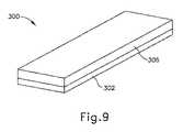
バットレス組立体(200)において、第1の接着層(204)の外縁は、第2の接着層(206)によって露出されたままである。図9、10は、第1の接着層(304)の外縁が第2の接着層(306)の下向きに突出する領域(308)によって被覆されている、例示的な代替のバットレス組立体(300)を示す。下向きに突出する領域(308)は、この例において、第1の接着層(304)の全幅及び全長に沿って延在する。下向きに突出する領域(308)はまた、バットレス本体(302)の上面と接触して下向きに延在する。したがって、バットレス本体(302)及び第2の接着層(306)は協働して、第1の接着層(304)を完全に封入する。バットレス本体(302)、第1の接着層(304)、及び第2の接着層(306)は、その他の点では、上記のバットレス本体(202)、第1の接着層(204)、及び第2の接着層(206)と同一であってもよい。接着層(304、306)がバットレス本体(302)と関連して構成及び配置され得る他の好適な方法は、本明細書の教示を考慮することで当業者には明らかになるであろう。 In the buttress assembly (200), the outer edge of the first adhesive layer (204) remains exposed by the second adhesive layer (206). 9 and 10 show an exemplary alternative buttress assembly (300) in which the outer edge of the first adhesive layer (304) is covered by a downwardly projecting region (308) of the second adhesive layer (306). ) Is shown. The downwardly projecting region (308) extends along the full width and overall length of the first adhesive layer (304) in this example. The downwardly projecting region (308) also extends downward in contact with the top surface of the buttress body (302). Therefore, the buttress body (302) and the second adhesive layer (306) work together to completely enclose the first adhesive layer (304). The buttress body (302), the first adhesive layer (304), and the second adhesive layer (306) are otherwise the buttress body (202), the first adhesive layer (204), and the first It may be the same as the adhesive layer (206) of 2. Other suitable methods in which the adhesive layer (304, 306) can be configured and arranged in connection with the buttress body (302) will become apparent to those skilled in the art by considering the teachings herein.
上記に加えて、本明細書で説明した様々なバットレス組立体のいずれもが、その開示内容が参照により本明細書に組み込まれる、2015年3月25日に出願された米国特許出願第14/667,842号、名称「Method of Applying a Buttress to a Surgical Stapler」の教示の少なくとも一部に従って更に構成され動作可能となり得ることが理解されよう。 In addition to the above, any of the various buttress assemblies described herein will be incorporated herein by reference in US Patent Application No. 14 /, filed March 25, 2015. It will be appreciated that it may be further configured and operational according to at least some of the teachings of No. 667,842, the name "Method of Applying a Buttress to a Surgical Stapler".
IV.例示的な組み合わせ
以下の実施例は、本明細書の教示を組み合わせるか又は適用することができる様々な非網羅的な方法に関する。以下の実施例は、本出願における又は本出願の後の出願におけるどの時点でも提示され得るいずれの請求項の適用範囲をも限定することを目的としたものではない点は理解されるべきである。一切の放棄を意図するものではない。以下の実施例は単なる例示の目的で与えられるものにすぎない。本明細書の様々な教示は、他の多くの方法で構成及び適用が可能であると企図される。また、いくつかの変形形態では、以下の実施例において言及される特定の特徴を省略してもよいことも企図される。したがって、本発明者によって、又は本発明者の利益となる継承者によって、後日、そうである旨が明示的に示されない限り、以下に言及される態様又は特徴のいずれも重要なものとしてみなされるべきではない。以下に言及される特徴以外の更なる特徴を含む請求項が本出願において、又は本出願に関連する後の出願において示される場合、これらの更なる特徴は、特許性に関連するいずれの理由によって追加されたものとしても仮定されるべきではない。IV. Illustrative Combinations The following examples relate to various non-exhaustive methods to which the teachings herein can be combined or applied. It should be understood that the following examples are not intended to limit the scope of any claim that may be presented at any time in this application or in subsequent applications. .. It is not intended to be abandoned at all. The following examples are provided for illustrative purposes only. It is contemplated that the various teachings herein can be constructed and applied in many other ways. It is also contemplated that in some variants, certain features referred to in the examples below may be omitted. Accordingly, any of the aspects or features referred to below will be deemed important unless expressly indicated at a later date by the inventor or by a successor in the interest of the inventor. Should not be. If a claim containing additional features other than those mentioned below is presented in this application or in a later application related to this application, these additional features may be for any reason relating to patentability. It should not be assumed as an addition.
(実施例1)
外科用ステープラエンドエフェクタ組立体であって、エンドエフェクタ組立体は、(a)ステープルカートリッジであって、ステープルカートリッジが、(i)複数のステープルと、(ii)デッキであって、ステープルカートリッジが、デッキを通してステープルを駆動させるように動作可能である、デッキと、を備える、ステープルカートリッジと、(b)アンビルであって、アンビルが、開放位置からステープルカートリッジに向かって、閉鎖位置に到達するように移動可能であり、アンビルが、デッキを通して駆動させられたステープルを受容するように構成されているステープル形成表面を有する下面を含む、アンビルと、(c)バットレス組立体であって、バットレス組立体が、ステープルカートリッジのデッキ又はアンビルの下面と連結されるように寸法決め及び構成されており、バットレス組立体が、(i)バットレス本体と、(ii)バットレス本体の上方に置かれた第1の接着層であって、第1の接着層が、第1の接着剤材料から形成されている、第1の接着層と、(iii)第1の接着層が第2の接着層とバットレス本体との間に挿入されるように、第1の接着層の上方に置かれた第2の接着層であって、第2の接着層が、第2の接着剤材料から形成され、第2の接着剤材料が第1の接着剤材料とは異なる、第2の接着層と、を備える、バットレス組立体と、を備える、エンドエフェクタ組立体。(Example 1)
Surgical stapler end effector assembly, the end effector assembly is (a) staple cartridges and staple cartridges are (i) multiple staples and (ii) decks and staple cartridges. A staple cartridge comprising a deck that is capable of driving the staples through the deck, and (b) an anvil so that the anvil reaches the closed position from the open position towards the staple cartridge. Anvil and (c) a batless assembly, the batless assembly comprising a lower surface that is movable and has a staple-forming surface that is configured for the anvil to receive staples driven through the deck. The staple assembly is sized and configured to be connected to the deck of the staple cartridge or the underside of the anvil, and the batless assembly is (i) a buttless body and (ii) a first bond placed above the buttless body. A first adhesive layer, wherein the first adhesive layer is formed of a first adhesive material, and (iii) the first adhesive layer is a second adhesive layer and a staple body. A second adhesive layer that is placed above the first adhesive layer so that it is inserted in between, the second adhesive layer being formed from the second adhesive material and the second adhesive. An end effector assembly comprising a batless assembly, comprising a second adhesive layer, the material of which is different from the first adhesive material.
(実施例2)
第2の接着層が、アンビルの下面に面するように位置付けられている、実施例1に記載のエンドエフェクタ組立体。(Example 2)
The end effector assembly according to the first embodiment, wherein the second adhesive layer is positioned so as to face the lower surface of the anvil.
(実施例3)
第2の接着層が、ステープルカートリッジのデッキに面するように位置付けられている、実施例1又は2のいずれか1つ又は2つ以上に記載のエンドエフェクタ組立体。(Example 3)
The end effector assembly according to any one or more of Examples 1 or 2, wherein the second adhesive layer is positioned to face the deck of the staple cartridge.
(実施例4)
第1の接着剤材料が、第2の接着剤材料よりも大きい柔軟性を有する、実施例1〜3のいずれか1つ又は2つ以上に記載のエンドエフェクタ組立体。(Example 4)
The end effector assembly according to any one or more of Examples 1 to 3, wherein the first adhesive material has greater flexibility than the second adhesive material.
(実施例5)
第1の接着剤材料が、第2の接着剤材料よりも大きい粘着性を有する、実施例1〜4のいずれか1つ又は2つ以上に記載のエンドエフェクタ組立体。(Example 5)
The end effector assembly according to any one or more of Examples 1 to 4, wherein the first adhesive material has greater adhesiveness than the second adhesive material.
(実施例6)
第2の接着剤材料が、第1の接着剤材料よりも大きい耐湿性を有する、実施例1〜5のいずれか1つ又は2つ以上に記載のエンドエフェクタ組立体。(Example 6)
The end effector assembly according to any one or more of Examples 1 to 5, wherein the second adhesive material has greater moisture resistance than the first adhesive material.
(実施例7)
第2の接着剤材料は、第1の接着剤材料よりも大きい耐温度性を有する、実施例1〜6のいずれか1つ又は2つ以上に記載のエンドエフェクタ組立体。(Example 7)
The end effector assembly according to any one or more of Examples 1 to 6, wherein the second adhesive material has a higher temperature resistance than the first adhesive material.
(実施例8)
第1及び第2の接着層が協働して、バットレス本体を、ステープルカートリッジのデッキ又はアンビルの下面のいずれかに接着するように構成されている、実施例1〜7のいずれか1つ又は2つ以上に記載のエンドエフェクタ組立体。(Example 8)
Any one of Examples 1-7 or one of Examples 1-7, wherein the first and second adhesive layers work together to bond the buttress body to either the deck of the staple cartridge or the underside of the anvil. The end effector assembly described in two or more.
(実施例9)
第1及び第2の接着剤材料が、異なる分子量ブレンドを有する、実施例1〜8のいずれか1つ又は2つ以上に記載のエンドエフェクタ組立体。(Example 9)
The end effector assembly according to any one or more of Examples 1 to 8, wherein the first and second adhesive materials have different molecular weight blends.
(実施例10)
第1及び第2の接着剤材料が、異なる架橋特性を有する、実施例1〜9のいずれか1つ又は2つ以上に記載のエンドエフェクタ組立体。(Example 10)
The end effector assembly according to any one or more of Examples 1 to 9, wherein the first and second adhesive materials have different cross-linking properties.
(実施例11)
第1及び第2の接着剤材料が、異なる族の接着剤材料から選択される、実施例1〜10のいずれか1つ又は2つ以上に記載のエンドエフェクタ組立体。(Example 11)
The end effector assembly according to any one or more of Examples 1 to 10, wherein the first and second adhesive materials are selected from different groups of adhesive materials.
(実施例12)
第2の接着剤材料が、バットレス本体と接触する領域を含む、実施例1〜11のいずれか1つ又は2つ以上に記載のエンドエフェクタ組立体。(Example 12)
The end effector assembly according to any one or more of Examples 1 to 11, wherein the second adhesive material comprises an area in contact with the buttress body.
(実施例13)
バットレス本体及びバットレス本体と接触する第2の接着剤材料の領域が協働して、第1の接着剤材料を封入する、実施例12に記載のエンドエフェクタ組立体。(Example 13)
The end effector assembly according to Example 12, wherein the buttress body and the region of the second adhesive material in contact with the buttress body work together to encapsulate the first adhesive material.
(実施例14)
第1の接着層が、長さを有し、バットレス本体と接触する第2の接着剤材料の領域が、第1の接着層の全長に沿って延在する、実施例12又は13のいずれか1つ又は2つ以上に記載のエンドエフェクタ組立体。(Example 14)
Either of Examples 12 or 13, the first adhesive layer has a length and the area of the second adhesive material in contact with the buttress body extends along the entire length of the first adhesive layer. The end effector assembly according to one or more.
(実施例15)
第1の接着層が、幅を有し、バットレス本体と接触する第2の接着剤材料の領域が、第1の接着層の全幅に沿って延在する、実施例12〜14のいずれか1つ又は2つ以上に記載のエンドエフェクタ組立体。(Example 15)
Any one of Examples 12-14, wherein the first adhesive layer has a width and the area of the second adhesive material in contact with the buttress body extends along the entire width of the first adhesive layer. One or two or more end effector assemblies.
(実施例16)
バットレス組立体が、アンビルの下面に接着され、ステープルが、バットレス組立体を通して駆動されるように位置付けられている、実施例1〜15のいずれか1つ又は2つ以上に記載のエンドエフェクタ組立体。(Example 16)
The end effector assembly according to any one or more of Examples 1-15, wherein the buttress assembly is glued to the underside of the anvil and the staples are positioned to be driven through the buttress assembly. ..
(実施例17)
外科用ステープラエンドエフェクタ組立体であって、エンドエフェクタ組立体は、(a)下側ジョーと、(b)アンビルであって、アンビルが、開放位置から下側ジョーに向かって、閉鎖位置に到達するように移動可能であり、アンビルが、ステープル形成表面を有する下面を含む、アンビルと、(c)アンビルの下面に固定されたバットレス組立体であって、バットレス組立体が、(i)バットレス本体と、(ii)バットレス本体の上方に置かれた第1の接着層であって、第1の接着層が、第1の接着剤材料から形成されている、第1の接着層と、(iii)第1の接着層が第2の接着層とバットレス本体との間に挿入されるように、第1の接着層の上方に置かれた第2の接着層であって、第2の接着層が、第2の接着剤材料から形成され、第2の接着剤材料が第1の接着剤材料とは異なる、第2の接着層と、を備える、バットレス組立体と、を備える、エンドエフェクタ組立体。(Example 17)
Surgical stayer End effector assembly, the end effector assembly is (a) lower jaw and (b) anvil, where the anvil reaches the closed position from the open position towards the lower jaw. The anvil is an anvil, including a lower surface having a staple-forming surface, and (c) a batless assembly fixed to the lower surface of the anvil, wherein the batless assembly is (i) a batless body. And (iii) a first adhesive layer, which is a first adhesive layer placed above the buttless body, wherein the first adhesive layer is formed from a first adhesive material, and (iii). A second adhesive layer that is placed above the first adhesive layer so that the first adhesive layer is inserted between the second adhesive layer and the buttless body. However, an end effector set comprising a buttless assembly, comprising a second adhesive layer, which is formed from a second adhesive material and the second adhesive material is different from the first adhesive material. Solid.
(実施例19)
外科用ステープラエンドエフェクタと使用するためのバットレス組立体を作製する方法であって、エンドエフェクタが、ステープルカートリッジと、アンビルと、を備え、ステープルカートリッジが、複数のステープルと、デッキと、を備え、ステープルカートリッジが、デッキを通してステープルを駆動させるように動作可能であり、アンビルが、開放位置からステープルカートリッジに向かって、閉鎖位置に到達するように移動可能であり、アンビルが、デッキを通して駆動させられたステープルを受容するように構成されたステープル形成表面を有する下面を含み、方法が、(a)第1の接着層をバットレス本体に適用することであって、バットレス本体が、ステープルカートリッジのデッキ又はアンビルの下面にはまるように寸法決め及び構成されており、第1の接着層が、第1の接着剤材料を含む、適用することと、(b)第1の接着層が第2の接着層とバットレス本体との間に挿入されるように、第2の接着層を第1の接着層に適用することであって、第2の接着層が、第2の接着剤材料から形成され、第2の接着剤材料が第1の接着剤材料とは異なる、適用することと、を含む、方法。(Example 19)
A method of making a buttless assembly for use with a surgical stapler end effector, wherein the end effector comprises a staple cartridge and an anvil, and the staple cartridge comprises a plurality of staples and a deck. The staple cartridge can be operated to drive the staples through the deck, the anvil can be moved from the open position towards the staple cartridge to reach the closed position, and the anvil is driven through the deck. Including a lower surface having a staple-forming surface configured to receive staples, the method is (a) applying a first adhesive layer to the staple body, where the staple cartridge deck or anvil. The first adhesive layer contains the first adhesive material and is applied, and (b) the first adhesive layer is the second adhesive layer. Applying the second adhesive layer to the first adhesive layer so that it is inserted between the staples and the body, the second adhesive layer is formed from the second adhesive material and the second. The method of applying the adhesive material is different from that of the first adhesive material.
(実施例19)
第2の接着層を第1の接着層に適用する行為が、第1の接着層上に第2の接着層を噴霧することを含む、実施例18に記載の方法。(Example 19)
The method of Example 18, wherein the act of applying the second adhesive layer to the first adhesive layer comprises spraying the second adhesive layer onto the first adhesive layer.
(実施例20)
アンビルの下面に対してバットレス組立体を押すことを更に含み、第1又は第2の接着剤材料のうちの一方又は両方が、アンビルの下面に対してバットレス組立体を押すことに応答して、バットレス組立体をアンビルの下面に固定する、実施例18又は19のいずれか1つ又は2つ以上に記載の方法。(Example 20)
Further comprising pushing the buttress assembly against the underside of the anvil, one or both of the first or second adhesive materials in response to pushing the buttress assembly against the underside of the anvil. The method of any one or more of Examples 18 or 19, wherein the buttress assembly is secured to the underside of the anvil.
V.その他
本明細書に記載の教示、表現要素、実施形態、実施例などのうちのいずれか1つ又は2つ以上を、本明細書に記載の他の教示、表現要素、実施形態、実施例などのうちのいずれか1つ又は2つ以上と組み合わせることができる点が理解されるべきである。したがって、上記の教示、表現要素、実施形態、実施例などは、互いに対して独立して考慮されるべきではない。本明細書の教示に照らして、本明細書の教示を組み合わせることができる様々な適当な方法が、当業者には直ちに明らかとなろう。かかる改変例及び変形例は、「特許請求の範囲」内に含まれるものとする。V. Others One or more of any one or more of the teachings, expression elements, embodiments, examples, etc. described in the present specification, other teachings, expression elements, embodiments, examples, etc. described in the present specification. It should be understood that it can be combined with any one or more of the two. Therefore, the above teachings, expression elements, embodiments, examples, etc. should not be considered independently of each other. Various suitable methods of combining the teachings herein will be immediately apparent to those skilled in the art in the light of the teachings herein. Such modifications and modifications shall be included in the "claims".
上記に加えて、本明細書で説明した様々なバットレス組立体のいずれもが、その開示内容が参照により本明細書に組み込まれる、2015年3月25日に出願された米国特許出願第14/667,842号、名称「Method of Applying a Buttress to a Surgical Stapler」、2015年8月17日に出願された米国特許出願第14/827,856号、名称「Implantable Layers for a Surgical Instrument」、その開示内容が参照により本明細書に組み込まれる、2015年9月30日に出願された米国特許出願第14/871,071号、名称「Compressible Adjunct with Crossing Spacer Fibers」、及び、その開示内容が参照により本明細書に組み込まれる、2015年9月30日に出願された米国特許出願第14/871,131号、名称「Method for Applying an Implantable Layer to a Fastener Cartridge」の教示の少なくとも一部に従って更に構成され得ることが理解されよう。更に、本明細書で説明した方法に加えて、本明細書で説明した様々なバットレス組立体のいずれもが、その開示内容が参照により本明細書に組み込まれる、2015年8月24日に出願された米国仮特許出願第62/209,041号、名称「Method and Apparatus for Applying a Buttress to End Effector of a Surgical Stapler」、及び/又は、その開示内容が参照により本明細書に組み込まれる、2015年9月30日に出願された米国特許出願第14/871,131号、名称「Method for Applying an Implantable Layer to a Fastener Cartridge」の教示の少なくとも一部に従ってエンドエフェクタ(40)に適用され得る。本明細書の教示が上記の引用文献の様々な教示と組み合わされ得る様々な適切な方法が、当業者には明らかとなろう。 In addition to the above, all of the various batless assemblies described herein are incorporated herein by reference in US Patent Application No. 14 /, filed March 25, 2015. 667,842, name "Method of Applying a Buttress to a Surgical Standard", US Patent Application No. 14 / 827,856 filed on August 17, 2015, name "Implantable Layers Forer US Patent Application No. 14 / 871,071 filed September 30, 2015, entitled "Compressible Adjunct with Crossing Spacer Fibers," and its disclosures, which are incorporated herein by reference. Further in accordance with at least some of the teachings of U.S. Patent Application No. 14 / 871,131, entitled "Method for Applying an Implantable Layer to a Fastener Cartridge," filed September 30, 2015, incorporated herein by. It will be understood that it can be configured. Further, in addition to the methods described herein, any of the various buttress assemblies described herein are filed on August 24, 2015, the disclosure of which is incorporated herein by reference. U.S. Provisional Patent Application No. 62 / 209,041, named "Method and Apparatus for Applying a Buttress to End Effector of a Surgical Stapler", and / or its disclosure is incorporated herein by reference. It can be applied to the end effector (40) in accordance with at least part of the teachings of US Patent Application No. 14 / 871,131, named "Method for Applying an Implantable Layer to a Buttress Cartridge," filed September 30, 2014. Various suitable methods will be apparent to those skilled in the art in which the teachings herein can be combined with the various teachings of the references cited above.
参照により本明細書に援用されると言及されたいかなる特許、刊行物、又は他の開示内容も、全体的に又は部分的に、援用された内容が現行の定義、見解、又は本開示に記載された他の開示内容とあくまで矛盾しない範囲でのみ本明細書に援用されることを認識されたい。それ自体、また必要な範囲で、本明細書に明瞭に記載される開示内容は、参照により本明細書に援用されるあらゆる矛盾する記載に優先するものとする。参照により本明細書に援用されるものとするが、既存の定義、記載、又は本明細書に記載される他の開示文献と矛盾する任意の文献、又はそれらの部分は、援用文献と既存の開示内容との間に矛盾が生じない範囲においてのみ援用されるものとする。 Any patents, publications, or other disclosures referred to herein by reference, in whole or in part, are described in the current definition, opinion, or disclosure. Please be aware that this is incorporated herein only to the extent that it is consistent with the other disclosures made. As such, and to the extent necessary, the disclosures expressly set forth herein shall supersede any contradictory statements incorporated herein by reference. Any document, or portion thereof, that is incorporated herein by reference but is inconsistent with existing definitions, descriptions, or other disclosed documents described herein is in reference and existing. It shall be incorporated only to the extent that there is no contradiction with the disclosed content.
上述の装置の変形形態は、医療専門家によって行われる従来の治療及び処置での用途だけでなく、ロボット支援された治療及び処置での用途も有することができる。あくまでも一例として、本明細書の様々な教示は、ロボット外科システム、例えばIntuitive Surgical,Inc.(Sunnyvale,California)によるDAVINCI(商標)システムに容易に組み込まれ得る。同様に、当業者であれば、本明細書における様々な教示が、以下の特許文献などのうちの任意のものの様々な教示と容易に組み合わされ得ることを認識するであろう:その開示が参照により本明細書に組み込まれている1998年8月11日に発行された米国特許第5,792,135号、名称「Articulated Surgical Instrument For Performing Minimally Invasive Surgery With Enhanced Dexterity and Sensitivity」、その開示内容が参照により本明細書に組み込まれる、1998年10月6日に発行された米国特許第5,817,084号、名称「Remote Center Positioning Device with Flexible Drive」、その開示内容が参照により本明細書に組み込まれる、1999年3月2日に発行された米国特許第5,878,193号、名称「Automated Endoscope System for Optimal Positioning」、その開示内容が参照により本明細書に組み込まれる、2001年5月15日に発行された米国特許第6,231,565号、名称「Robotic Arm DLUS for Performing Surgical Tasks」、その開示内容が参照により本明細書に組み込まれる、2004年8月31日に発行された米国特許第6,783,524号、名称「Robotic Surgical Tool with Ultrasound Cauterizing and Cutting Instrument」、その開示内容が参照により本明細書に組み込まれる、2002年4月2日に発行された米国特許第6,364,888号、名称「Alignment of Master and Slave in a Minimally Invasive Surgical Apparatus」、その開示内容が参照により本明細書に組み込まれる、2009年4月28日に発行された米国特許第7,524,320号、名称「Mechanical Actuator Interface System for Robotic Surgical Tools」、その開示内容が参照により本明細書に組み込まれる、2010年4月6日に発行された米国特許第7,691,098号、名称「Platform Link Wrist Mechanism」、その開示内容が参照により本明細書に組み込まれる、2010年10月5日に発行された米国特許第7,806,891号、名称「Repositioning and Reorientation of Master/Slave Relationship in Minimally Invasive Telesurgery」、その開示が参照により本明細書に組み込まれる、2013年1月10日に公開された米国特許公開第2013/0012957号、名称「Automated End Effector Component Reloading System for Use with a Robotic System」、その開示が参照により本明細書に組み込まれる、2012年8月9日に公開された米国特許公開第2012/0199630号、名称「Robotically−Controlled Surgical Instrument with Force−Feedback Capabilities」、その開示が参照により本明細書に組み込まれる、2012年5月31日に公開された米国特許公開第2012/0132450号、名称「Shiftable Drive Interface for Robotically−Controlled Surgical Tool」、その開示が参照により本明細書に組み込まれる、2012年8月9日に公開された米国特許公開第2012/0199633号、名称「Surgical Stapling Instruments with Cam−Driven Staple Deployment Arrangements」、その開示が参照により本明細書に組み込まれる、2012年8月9日に公開された米国特許公開第2012/0199631号、名称「Robotically−Controlled Motorized Surgical End Effector System with Rotary Actuated Closure Systems Having Variable Actuation Speeds」、その開示が参照により本明細書に組み込まれる、2012年8月9日に公開された米国特許公開第2012/0199632号、名称「Robotically−Controlled Surgical Instrument with Selectively Articulatable End Effector」、その開示が参照により本明細書に組み込まれる、2012年8月9日に公開された米国特許公開第2012/0203247号、名称「Robotically−Controlled Surgical End Effector System」、2012年8月23日に公開された米国特許公開第2012/0211546号、名称「Drive Interface for Operably Coupling a Manipulatable Surgical Tool to a Robot」、その開示が参照により本明細書に組み込まれる、2012年6月7日に公開された米国特許公開第2012/0138660号、名称「Robotically−Controlled Cable−Based Surgical End Effectors」、及び/又は、その開示が参照により本明細書に組み込まれている2012年8月16日に公開された米国特許公開第2012/0205421号、名称「Robotically−Controlled Surgical End Effector System with Rotary Actuated Closure Systems」。 The variants of the device described above can have applications in robot-assisted therapies and procedures as well as in conventional therapies and procedures performed by medical professionals. As an example only, the various teachings herein are described in robotic surgical systems such as Intuitive Surgical, Inc. It can be easily incorporated into the DAVINCI ™ system by (Sunnyvale, California). Similarly, those skilled in the art will recognize that the various teachings herein can be easily combined with the various teachings of any of the following patent documents and the like: the disclosure thereof is referenced. US Pat. No. 5,792,135 issued on August 11, 1998, entitled "Artificated Surgical Instrument For Performance For Performance Minimally Invasive Surgical With Disclosed Content", incorporated herein by. US Pat. No. 5,817,084, issued October 6, 1998, entitled "Remote Center Positioning Device with Flexible Drive," which is incorporated herein by reference, the disclosure of which is incorporated herein by reference. Incorporated, US Pat. No. 5,878,193 issued March 2, 1999, entitled "Automated Endoscop System for Optimal Positioning", the disclosure of which is incorporated herein by reference, May 2001. US Pat. No. 6,231,565 issued on 15th, named "Robotic Arm DLUS for Performance Surgical Tasks", issued August 31, 2004, the disclosure of which is incorporated herein by reference. US Pat. No. 6,783,524, entitled "Robotic Surgical Tool with Ultrasond Cauting and Cutting Instrument," US Pat. No. 6, issued April 2, 2002, the disclosure of which is incorporated herein by reference. , 364,888, name "Asignment of Master and Slave in a Minimally Invasive Surgical Apparatus," US Pat. No. 7,524, issued April 28, 2009, the disclosure of which is incorporated herein by reference. , No. 320, name "Mechanical Actuator Interface System for Robot" "ic Surgical Tools", US Pat. No. 7,691,098 issued on April 6, 2010, the disclosure of which is incorporated herein by reference, the name "Platform Link Wrist Mechanism", the disclosure of which is US Pat. No. 7,806,891, issued October 5, 2010, incorporated herein by reference, entitled "Repositioning and Reorientation of Master / Slave Relationship in Minimally Invasive Telesurry". US Pat. Incorporated in, U.S. Patent Publication No. 2012/0199630, published August 9, 2012, entitled "Robotically-Controlled Surgical Instrument", the disclosure of which is incorporated herein by reference. US Pat. Published US Pat. Published No. 2012/0199631, named "Locally-Control Motorized Surgical End Effector System with Rotary A" Ctuated Closure Systems Haveing Variable Action Speeds, the disclosure of which is incorporated herein by reference, U.S. Patent Publication No. 2012/0199632, published August 9, 2012, entitled "Robotically-ControlicalSulbul. "End Effector", the disclosure of which is incorporated herein by reference, US Patent Publication No. 2012/0203247, published August 9, 2012, named "Robotically-Control Surgical End Effector System", August 2012. US Patent Publication No. 2012/0211546, published on the 23rd, entitled "Drive Interface for Opera Coupling a Manipulable Surgical Tool to a Robot", the disclosure of which is incorporated herein by reference, June 2012. Published US Patent Publication No. 2012/01386660, entitled "Robotically-Control Cable-Based Surgical End Effects", and / or published on August 16, 2012, the disclosure of which is incorporated herein by reference. Published in US Patent Publication No. 2012/0205421, named "Robotically-Controlled Surgical End Effect System with Rotary Actuated Color Systems".
上述の装置の変形例は、1回の使用後に処分するように設計されることができ、又はそれらは、複数回使用するように設計することができる。いずれか又は両方の場合において、変形形態は、少なくとも1回の使用後に再利用のために再調整され得る。再調整は、デバイスの分解工程、それに続く特定の部品の洗浄又は交換工程、及びその後の再組立工程の任意の組み合わせを含み得る。特に、装置のいくつかの変形形態は分解することができ、また、装置の任意の数の特定の部材又は部品を、任意の組み合わせで選択的に交換するか又は取り外してもよい。特定の部品の洗浄及び/又は交換に際して、装置の特定の変形形態を、再調整用の施設において、又は手術の直前に使用者により再組み立てして、その後の使用に供することができる。当業者であれば、デバイスの再調整において、分解、洗浄/交換、及び再組立のための様々な技術を使用できる点を認識するであろう。かかる技術の使用、及び結果として得られる再調整された装置は、すべて本出願の範囲内にある。 Modifications of the devices described above can be designed to be disposed of after a single use, or they can be designed to be used multiple times. In either or both cases, the modified form may be readjusted for reuse after at least one use. The readjustment may include any combination of a device disassembly step, followed by a cleaning or replacement step of a particular part, and a subsequent reassembly step. In particular, some variants of the device can be disassembled and any number of specific members or parts of the device may be selectively replaced or removed in any combination. Upon cleaning and / or replacement of certain parts, certain variants of the device may be reassembled by the user in a readjustment facility or shortly before surgery for subsequent use. Those skilled in the art will recognize that various techniques for disassembly, cleaning / replacement, and reassembly can be used in readjustment of the device. The use of such techniques and the resulting readjustment device are all within the scope of this application.
あくまで一例として、本明細書に記載される変形形態は、手術の前及び/又は後に滅菌されてもよい。1つの滅菌法では、装置をプラスチック製又はTYVEK製のバックなどの閉鎖及び密封された容器に入れる。次いで、容器及び装置を、γ線、X線、又は高エネルギー電子線などの、容器を透過し得る放射線場に置くことができる。放射線は、装置の表面及び容器内の細菌を死滅させることができる。この後、滅菌された装置を、後の使用のために、滅菌容器中で保管することができる。デバイスはまた、β線若しくはγ線、エチレンオキシド、又は水蒸気が挙げられるがこれらに限定されない、当該技術分野で既知の任意の別の技術を用いて滅菌され得る。 As an example, the variants described herein may be sterilized before and / or after surgery. In one sterilization method, the device is placed in a closed and sealed container such as a plastic or TYVEK bag. The vessel and device can then be placed in a radiation field that can penetrate the vessel, such as gamma rays, X-rays, or high energy electron beams. Radiation can kill bacteria on the surface of the device and in the container. After this, the sterilized device can be stored in a sterilized container for later use. The device can also be sterilized using any other technique known in the art, including but not limited to beta or gamma rays, ethylene oxide, or water vapor.
以上、本発明の様々な実施形態を図示及び説明したが、本発明の範囲から逸脱することなく、当業者による適切な改変により、本明細書に記載される方法及びシステムの更なる適合化を実現することができる。そのような可能な改変のうちのいくつかについて述べたが、他の改変も当業者には明らかであろう。例えば、上記で論じた実施例、実施形態、形状、材料、寸法、比率、工程などは例示的なものであって、必須のものではない。したがって、本発明の範囲は、以下の特許請求の範囲の観点から考慮されるべきものであり、本明細書及び図面において図示され、説明された構造及び動作の細部に限定されないものとして理解されたい。 Although various embodiments of the present invention have been illustrated and described above, further adaptation of the methods and systems described herein can be made by appropriate modification by those skilled in the art without departing from the scope of the present invention. It can be realized. Some of such possible modifications have been mentioned, but other modifications will be apparent to those skilled in the art. For example, the examples, embodiments, shapes, materials, dimensions, ratios, processes, etc. discussed above are exemplary and not essential. Therefore, the scope of the present invention should be considered in terms of the following claims and should be understood as not limited to the structural and operational details illustrated and described herein and in the drawings. ..
〔実施の態様〕
(1) 外科用ステープラエンドエフェクタ組立体であって、前記エンドエフェクタ組立体は、
(a)ステープルカートリッジであって、前記ステープルカートリッジは、
(i)複数のステープルと、
(ii)デッキであって、前記ステープルカートリッジが、前記デッキを通して前記ステープルを駆動させるように動作可能である、デッキと、を備える、ステープルカートリッジと、
(b)アンビルであって、前記アンビルが、開放位置から前記ステープルカートリッジに向かって、閉鎖位置に到達するように移動可能であり、前記アンビルが、前記デッキを通して駆動させられたステープルを受容するように構成されているステープル形成表面を有する下面を含む、アンビルと、
(c)バットレス組立体であって、前記バットレス組立体が、前記ステープルカートリッジの前記デッキ又は前記アンビルの前記下面と連結されるように寸法決め及び構成されており、前記バットレス組立体が、
(i)バットレス本体と、
(ii)前記バットレス本体の上方に置かれた第1の接着層であって、前記第1の接着層が、第1の接着剤材料から形成されている、第1の接着層と、
(iii)前記第1の接着層が第2の接着層と前記バットレス本体との間に挿入されるように、前記第1の接着層の上方に置かれた前記第2の接着層であって、前記第2の接着層が、第2の接着剤材料から形成され、前記第2の接着剤材料が前記第1の接着剤材料とは異なる、第2の接着層と、を備える、バットレス組立体と、を備える、エンドエフェクタ組立体。
(2) 前記第2の接着層が、前記アンビルの前記下面に面するように位置付けられている、実施態様1に記載のエンドエフェクタ組立体。
(3) 前記第2の接着層が、前記ステープルカートリッジの前記デッキに面するように位置付けられている、実施態様1に記載のエンドエフェクタ組立体。
(4) 前記第1の接着剤材料が、前記第2の接着剤材料よりも大きい柔軟性を有する、実施態様1に記載のエンドエフェクタ組立体。
(5) 前記第1の接着剤材料が、前記第2の接着剤材料よりも大きい粘着性を有する、実施態様1に記載のエンドエフェクタ組立体。[Implementation mode]
(1) A surgical stapler end effector assembly, wherein the end effector assembly is
(A) A staple cartridge, the staple cartridge is
(I) Multiple staples and
(Ii) A staple cartridge comprising a deck, wherein the staple cartridge is capable of operating to drive the staple through the deck.
(B) Anvil so that the anvil can move from the open position towards the staple cartridge to reach the closed position and the anvil receives the staples driven through the deck. Anvil, including a lower surface with a staple-forming surface configured in
(C) A buttress assembly that is dimensioned and configured such that the buttress assembly is connected to the deck of the staple cartridge or the underside of the anvil.
(I) Buttress body and
(Ii) A first adhesive layer, which is a first adhesive layer placed above the buttress body, wherein the first adhesive layer is formed of a first adhesive material.
(Iii) The second adhesive layer placed above the first adhesive layer so that the first adhesive layer is inserted between the second adhesive layer and the buttless body. , A batless assembly comprising a second adhesive layer, wherein the second adhesive layer is formed from a second adhesive material and the second adhesive material is different from the first adhesive material. An end effector assembly with a solid.
(2) The end effector assembly according to the first embodiment, wherein the second adhesive layer is positioned so as to face the lower surface of the anvil.
(3) The end effector assembly according to the first embodiment, wherein the second adhesive layer is positioned so as to face the deck of the staple cartridge.
(4) The end effector assembly according to the first embodiment, wherein the first adhesive material has greater flexibility than the second adhesive material.
(5) The end effector assembly according to the first embodiment, wherein the first adhesive material has a greater adhesiveness than the second adhesive material.
(6) 前記第2の接着剤材料が、前記第1の接着剤材料よりも大きい耐湿性を有する、実施態様1に記載のエンドエフェクタ組立体。
(7) 前記第2の接着剤材料が、前記第1の接着剤材料よりも大きい耐温度性を有する、実施態様1に記載のエンドエフェクタ組立体。
(8) 前記第1及び第2の接着層が協働して、前記バットレス本体を、前記ステープルカートリッジの前記デッキ又は前記アンビルの前記下面のいずれかに接着するように構成されている、実施態様1に記載のエンドエフェクタ組立体。
(9) 前記第1及び第2の接着剤材料が、異なる分子量ブレンドを有する、実施態様1に記載のエンドエフェクタ組立体。
(10) 前記第1及び第2の接着剤材料が、異なる架橋特性を有する、実施態様1に記載のエンドエフェクタ組立体。(6) The end effector assembly according to the first embodiment, wherein the second adhesive material has greater moisture resistance than the first adhesive material.
(7) The end effector assembly according to the first embodiment, wherein the second adhesive material has a higher temperature resistance than the first adhesive material.
(8) An embodiment in which the first and second adhesive layers cooperate to bond the buttress body to either the deck of the staple cartridge or the lower surface of the anvil. The end effector assembly according to 1.
(9) The end effector assembly according to
(10) The end effector assembly according to the first embodiment, wherein the first and second adhesive materials have different cross-linking properties.
(11) 前記第1及び第2の接着剤材料が、異なる族の接着剤材料から選択される、実施態様1に記載のエンドエフェクタ組立体。
(12) 前記第2の接着剤材料が、前記バットレス本体と接触する領域を含む、実施態様1に記載のエンドエフェクタ組立体。
(13) 前記バットレス本体及び前記バットレス本体と接触する前記第2の接着剤材料の前記領域が、協働して、前記第1の接着剤材料を封入する、実施態様12に記載のエンドエフェクタ組立体。
(14) 前記第1の接着層が、長さを有し、前記バットレス本体と接触する前記第2の接着剤材料の前記領域が、前記第1の接着層の前記全長に沿って延在する、実施態様12に記載のエンドエフェクタ組立体。
(15) 前記第1の接着層が、幅を有し、前記バットレス本体と接触する前記第2の接着剤材料の前記領域が、前記第1の接着層の前記全幅に沿って延在する、実施態様12に記載のエンドエフェクタ組立体。(11) The end effector assembly according to the first embodiment, wherein the first and second adhesive materials are selected from different groups of adhesive materials.
(12) The end effector assembly according to the first embodiment, wherein the second adhesive material includes a region in contact with the buttress body.
(13) The end effector assembly according to the twelfth embodiment, wherein the buttress main body and the region of the second adhesive material in contact with the buttress main body cooperate to enclose the first adhesive material. Three-dimensional.
(14) The first adhesive layer has a length, and the region of the second adhesive material in contact with the buttress body extends along the entire length of the first adhesive layer. , The end effector assembly according to the twelfth embodiment.
(15) The first adhesive layer has a width, and the region of the second adhesive material in contact with the buttress body extends along the entire width of the first adhesive layer. The end effector assembly according to embodiment 12.
(16) 前記バットレス組立体が、前記アンビルの前記下面に接着され、前記ステープルが、前記バットレス組立体を通して駆動されるように位置付けられている、実施態様1に記載のエンドエフェクタ組立体。
(17) 外科用ステープラエンドエフェクタ組立体であって、前記エンドエフェクタ組立体は、
(a)下側ジョーと、
(b)アンビルであって、前記アンビルが、開放位置から前記下側ジョーに向かって、閉鎖位置に到達するように移動可能であり、前記アンビルが、ステープル形成表面を有する下面を含む、アンビルと、
(c)前記アンビルの前記下面に固定されたバットレス組立体であって、前記バットレス組立体が、
(i)バットレス本体と、
(ii)前記バットレス本体の上方に置かれた第1の接着層であって、前記第1の接着層が、第1の接着剤材料から形成されている、第1の接着層と、
(iii)前記第1の接着層が第2の接着層と前記バットレス本体との間に挿入されるように、前記第1の接着層の上方に置かれた前記第2の接着層であって、前記第2の接着層が、第2の接着剤材料から形成され、前記第2の接着剤材料が前記第1の接着剤材料とは異なる、第2の接着層と、を備える、バットレス組立体と、を備える、エンドエフェクタ組立体。
(18) 外科用ステープラエンドエフェクタと使用するためのバットレス組立体を作製する方法であって、前記エンドエフェクタが、ステープルカートリッジと、アンビルと、を備え、前記ステープルカートリッジが、複数のステープルと、デッキと、を備え、前記ステープルカートリッジが、前記デッキを通して前記ステープルを駆動させるように動作可能であり、前記アンビルが、開放位置から前記ステープルカートリッジに向かって、閉鎖位置に到達するように移動可能であり、前記アンビルが、前記デッキを通して駆動させられたステープルを受容するように構成されたステープル形成表面を有する下面を含み、前記方法が、
(a)第1の接着層をバットレス本体に適用することであって、前記バットレス本体が、前記ステープルカートリッジの前記デッキ又は前記アンビルの前記下面にはまるように寸法決め及び構成されており、前記第1の接着層が、第1の接着剤材料を含む、適用することと、
(b)前記第1の接着層が第2の接着層と前記バットレス本体との間に挿入されるように、前記第2の接着層を前記第1の接着層に適用することであって、前記第2の接着層が、第2の接着剤材料から形成され、前記第2の接着剤材料が前記第1の接着剤材料とは異なる、適用することと、を含む、方法。
(19) 前記第2の接着層を前記第1の接着層に適用する行為が、前記第1の接着層上に前記第2の接着層を噴霧することを含む、実施態様18に記載の方法。
(20) 前記アンビルの前記下面に対して前記バットレス組立体を押すことを更に含み、前記第1又は第2の接着剤材料のうちの一方又は両方が、前記アンビルの前記下面に対して前記バットレス組立体を押すことに応答して、前記バットレス組立体を前記アンビルの前記下面に固定する、実施態様18に記載の方法。(16) The end effector assembly according to
(17) A surgical stapler end effector assembly, wherein the end effector assembly is
(A) With the lower jaw
(B) An anvil, wherein the anvil is movable from an open position toward the lower jaw so as to reach a closed position, and the anvil includes a lower surface having a staple-forming surface. ,
(C) A buttress assembly fixed to the lower surface of the anvil, wherein the buttress assembly is
(I) Buttress body and
(Ii) A first adhesive layer, which is a first adhesive layer placed above the buttress body, wherein the first adhesive layer is formed of a first adhesive material.
(Iii) The second adhesive layer placed above the first adhesive layer so that the first adhesive layer is inserted between the second adhesive layer and the buttless body. , A batless assembly comprising a second adhesive layer, wherein the second adhesive layer is formed from a second adhesive material and the second adhesive material is different from the first adhesive material. An end effector assembly with a solid.
(18) A method of making a buttless assembly for use with a surgical stapler end effector, wherein the end effector comprises a staple cartridge and an anvil, and the staple cartridge includes a plurality of staples and a deck. The staple cartridge can be operated to drive the staple through the deck, and the anvil can be moved from the open position toward the staple cartridge so as to reach the closed position. The method comprises a lower surface having a staple-forming surface configured such that the anvil receives staples driven through the deck.
(A) The first adhesive layer is applied to the buttress body, and the buttress body is dimensioned and configured so as to fit into the deck of the staple cartridge or the lower surface of the anvil. Applying, where one adhesive layer contains a first adhesive material,
(B) Applying the second adhesive layer to the first adhesive layer so that the first adhesive layer is inserted between the second adhesive layer and the buttless body. A method comprising applying that the second adhesive layer is formed from a second adhesive material and the second adhesive material is different from the first adhesive material.
(19) The method according to embodiment 18, wherein the act of applying the second adhesive layer to the first adhesive layer comprises spraying the second adhesive layer onto the first adhesive layer. ..
(20) Further comprising pushing the buttress assembly against the lower surface of the anvil, one or both of the first or second adhesive material being the buttress against the lower surface of the anvil. 18. The method of embodiment 18, wherein the buttress assembly is secured to the underside of the anvil in response to pushing the assembly.
Claims (15)
Translated fromJapanese(a)ステープルカートリッジであって、前記ステープルカートリッジは、
(i)複数のステープルと、
(ii)デッキであって、前記ステープルカートリッジが、前記デッキを通して前記ステープルを駆動させるように動作可能である、デッキと、を備える、ステープルカートリッジと、
(b)アンビルであって、前記アンビルが、開放位置から前記ステープルカートリッジに向かって、閉鎖位置に到達するように移動可能であり、前記アンビルが、前記デッキを通して駆動させられたステープルを受容するように構成されているステープル形成表面を有する下面を含む、アンビルと、
(c)バットレス組立体であって、前記バットレス組立体が、前記ステープルカートリッジの前記デッキ又は前記アンビルの前記下面と連結されるように寸法決め及び構成されており、前記バットレス組立体が、
(i)バットレス本体と、
(ii)前記バットレス本体の上方に置かれた第1の接着層であって、前記第1の接着層が、第1の接着剤材料から形成されている、第1の接着層と、
(iii)前記第1の接着層が第2の接着層と前記バットレス本体との間に挿入されるように、前記第1の接着層の上方に置かれた前記第2の接着層であって、前記第2の接着層が、第2の接着剤材料から形成され、前記第2の接着剤材料が前記第1の接着剤材料とは異なる、第2の接着層と、を備え、
前記第1の接着剤材料が前記第2の接着剤材料よりも大きい柔軟性または粘着性を有する、バットレス組立体と、を備える、外科用ステープラエンドエフェクタ組立体。A surgical stapler end effector assembly, wherein thesurgical stapler end effector assembly is
(A) A staple cartridge, the staple cartridge is
(I) Multiple staples and
(Ii) A staple cartridge comprising a deck, wherein the staple cartridge is capable of operating to drive the staple through the deck.
(B) Anvil so that the anvil can move from the open position towards the staple cartridge to reach the closed position and the anvil receives the staples driven through the deck. Anvil, including a lower surface with a staple-forming surface configured in
(C) A buttress assembly that is dimensioned and configured such that the buttress assembly is connected to the deck of the staple cartridge or the underside of the anvil.
(I) Buttress body and
(Ii) A first adhesive layer, which is a first adhesive layer placed above the buttress body, wherein the first adhesive layer is formed of a first adhesive material.
(Iii) The second adhesive layer placed above the first adhesive layer so that the first adhesive layer is inserted between the second adhesive layer and the buttless body. the second adhesive layer is formed from a second adhesive material, said different from the second adhesive material is the first adhesive material,e Bei a second adhesive layer,and
A surgical stapler end effector assembly comprising a buttress assembly inwhich the first adhesive material has greater flexibility or stickiness than the second adhesive material.
(a)下側ジョーと、
(b)アンビルであって、前記アンビルが、開放位置から前記下側ジョーに向かって、閉鎖位置に到達するように移動可能であり、前記アンビルが、ステープル形成表面を有する下面を含む、アンビルと、
(c)前記アンビルの前記下面に固定されたバットレス組立体であって、前記バットレス組立体が、
(i)バットレス本体と、
(ii)前記バットレス本体の上方に置かれた第1の接着層であって、前記第1の接着層が、第1の接着剤材料から形成されている、第1の接着層と、
(iii)前記第1の接着層が第2の接着層と前記バットレス本体との間に挿入されるように、前記第1の接着層の上方に置かれた前記第2の接着層であって、前記第2の接着層が、第2の接着剤材料から形成され、前記第2の接着剤材料が前記第1の接着剤材料とは異なる、第2の接着層と、を備え、
前記第1の接着剤材料が前記第2の接着剤材料よりも大きい柔軟性または粘着性を有する、バットレス組立体と、を備える、外科用ステープラエンドエフェクタ組立体。A surgical stapler end effector assembly, wherein thesurgical stapler end effector assembly is
(A) With the lower jaw
(B) An anvil, wherein the anvil is movable from an open position toward the lower jaw so as to reach a closed position, and the anvil includes a lower surface having a staple-forming surface. ,
(C) A buttress assembly fixed to the lower surface of the anvil, wherein the buttress assembly is
(I) Buttress body and
(Ii) A first adhesive layer, which is a first adhesive layer placed above the buttress body, wherein the first adhesive layer is formed of a first adhesive material.
(Iii) The second adhesive layer placed above the first adhesive layer so that the first adhesive layer is inserted between the second adhesive layer and the buttless body. the second adhesive layer is formed from a second adhesive material, said different from the second adhesive material is the first adhesive material,e Bei a second adhesive layer,and
A surgical stapler end effector assembly comprising a buttress assembly inwhich the first adhesive material has greater flexibility or stickiness than the second adhesive material.
Applications Claiming Priority (3)
| Application Number | Priority Date | Filing Date | Title |
|---|---|---|---|
| US14/926,160US10441286B2 (en) | 2015-10-29 | 2015-10-29 | Multi-layer surgical stapler buttress assembly |
| US14/926,160 | 2015-10-29 | ||
| PCT/US2016/058398WO2017074844A1 (en) | 2015-10-29 | 2016-10-24 | Surgical stapler buttress assembly with multi-layer adhesive |
Publications (2)
| Publication Number | Publication Date |
|---|---|
| JP2018536467A JP2018536467A (en) | 2018-12-13 |
| JP6926076B2true JP6926076B2 (en) | 2021-08-25 |
Family
ID=57211396
Family Applications (1)
| Application Number | Title | Priority Date | Filing Date |
|---|---|---|---|
| JP2018522073AActiveJP6926076B2 (en) | 2015-10-29 | 2016-10-24 | Multi-layer surgical stapler buttress assembly |
Country Status (6)
| Country | Link |
|---|---|
| US (1) | US10441286B2 (en) |
| EP (2) | EP3162302B1 (en) |
| JP (1) | JP6926076B2 (en) |
| CN (1) | CN108348253B (en) |
| BR (1) | BR112018008559B1 (en) |
| WO (1) | WO2017074844A1 (en) |
Families Citing this family (423)
| Publication number | Priority date | Publication date | Assignee | Title |
|---|---|---|---|---|
| US20070084897A1 (en) | 2003-05-20 | 2007-04-19 | Shelton Frederick E Iv | Articulating surgical stapling instrument incorporating a two-piece e-beam firing mechanism |
| US9060770B2 (en) | 2003-05-20 | 2015-06-23 | Ethicon Endo-Surgery, Inc. | Robotically-driven surgical instrument with E-beam driver |
| US8215531B2 (en) | 2004-07-28 | 2012-07-10 | Ethicon Endo-Surgery, Inc. | Surgical stapling instrument having a medical substance dispenser |
| US11890012B2 (en) | 2004-07-28 | 2024-02-06 | Cilag Gmbh International | Staple cartridge comprising cartridge body and attached support |
| US11998198B2 (en) | 2004-07-28 | 2024-06-04 | Cilag Gmbh International | Surgical stapling instrument incorporating a two-piece E-beam firing mechanism |
| US9072535B2 (en) | 2011-05-27 | 2015-07-07 | Ethicon Endo-Surgery, Inc. | Surgical stapling instruments with rotatable staple deployment arrangements |
| US9237891B2 (en) | 2005-08-31 | 2016-01-19 | Ethicon Endo-Surgery, Inc. | Robotically-controlled surgical stapling devices that produce formed staples having different lengths |
| US11484312B2 (en) | 2005-08-31 | 2022-11-01 | Cilag Gmbh International | Staple cartridge comprising a staple driver arrangement |
| US7934630B2 (en) | 2005-08-31 | 2011-05-03 | Ethicon Endo-Surgery, Inc. | Staple cartridges for forming staples having differing formed staple heights |
| US11246590B2 (en) | 2005-08-31 | 2022-02-15 | Cilag Gmbh International | Staple cartridge including staple drivers having different unfired heights |
| US10159482B2 (en) | 2005-08-31 | 2018-12-25 | Ethicon Llc | Fastener cartridge assembly comprising a fixed anvil and different staple heights |
| US7669746B2 (en) | 2005-08-31 | 2010-03-02 | Ethicon Endo-Surgery, Inc. | Staple cartridges for forming staples having differing formed staple heights |
| US20070106317A1 (en) | 2005-11-09 | 2007-05-10 | Shelton Frederick E Iv | Hydraulically and electrically actuated articulation joints for surgical instruments |
| US11278279B2 (en) | 2006-01-31 | 2022-03-22 | Cilag Gmbh International | Surgical instrument assembly |
| US7753904B2 (en) | 2006-01-31 | 2010-07-13 | Ethicon Endo-Surgery, Inc. | Endoscopic surgical instrument with a handle that can articulate with respect to the shaft |
| US7845537B2 (en) | 2006-01-31 | 2010-12-07 | Ethicon Endo-Surgery, Inc. | Surgical instrument having recording capabilities |
| US11224427B2 (en) | 2006-01-31 | 2022-01-18 | Cilag Gmbh International | Surgical stapling system including a console and retraction assembly |
| US8186555B2 (en) | 2006-01-31 | 2012-05-29 | Ethicon Endo-Surgery, Inc. | Motor-driven surgical cutting and fastening instrument with mechanical closure system |
| US20120292367A1 (en) | 2006-01-31 | 2012-11-22 | Ethicon Endo-Surgery, Inc. | Robotically-controlled end effector |
| US11793518B2 (en) | 2006-01-31 | 2023-10-24 | Cilag Gmbh International | Powered surgical instruments with firing system lockout arrangements |
| US8708213B2 (en) | 2006-01-31 | 2014-04-29 | Ethicon Endo-Surgery, Inc. | Surgical instrument having a feedback system |
| US20110024477A1 (en) | 2009-02-06 | 2011-02-03 | Hall Steven G | Driven Surgical Stapler Improvements |
| US20110295295A1 (en) | 2006-01-31 | 2011-12-01 | Ethicon Endo-Surgery, Inc. | Robotically-controlled surgical instrument having recording capabilities |
| US8820603B2 (en) | 2006-01-31 | 2014-09-02 | Ethicon Endo-Surgery, Inc. | Accessing data stored in a memory of a surgical instrument |
| US8992422B2 (en) | 2006-03-23 | 2015-03-31 | Ethicon Endo-Surgery, Inc. | Robotically-controlled endoscopic accessory channel |
| US8322455B2 (en) | 2006-06-27 | 2012-12-04 | Ethicon Endo-Surgery, Inc. | Manually driven surgical cutting and fastening instrument |
| US10568652B2 (en) | 2006-09-29 | 2020-02-25 | Ethicon Llc | Surgical staples having attached drivers of different heights and stapling instruments for deploying the same |
| US7506791B2 (en) | 2006-09-29 | 2009-03-24 | Ethicon Endo-Surgery, Inc. | Surgical stapling instrument with mechanical mechanism for limiting maximum tissue compression |
| US11980366B2 (en) | 2006-10-03 | 2024-05-14 | Cilag Gmbh International | Surgical instrument |
| US8684253B2 (en) | 2007-01-10 | 2014-04-01 | Ethicon Endo-Surgery, Inc. | Surgical instrument with wireless communication between a control unit of a robotic system and remote sensor |
| US11291441B2 (en) | 2007-01-10 | 2022-04-05 | Cilag Gmbh International | Surgical instrument with wireless communication between control unit and remote sensor |
| US8652120B2 (en) | 2007-01-10 | 2014-02-18 | Ethicon Endo-Surgery, Inc. | Surgical instrument with wireless communication between control unit and sensor transponders |
| US8632535B2 (en) | 2007-01-10 | 2014-01-21 | Ethicon Endo-Surgery, Inc. | Interlock and surgical instrument including same |
| US11039836B2 (en) | 2007-01-11 | 2021-06-22 | Cilag Gmbh International | Staple cartridge for use with a surgical stapling instrument |
| US20080169333A1 (en) | 2007-01-11 | 2008-07-17 | Shelton Frederick E | Surgical stapler end effector with tapered distal end |
| US7673782B2 (en) | 2007-03-15 | 2010-03-09 | Ethicon Endo-Surgery, Inc. | Surgical stapling instrument having a releasable buttress material |
| US8893946B2 (en) | 2007-03-28 | 2014-11-25 | Ethicon Endo-Surgery, Inc. | Laparoscopic tissue thickness and clamp load measuring devices |
| US8931682B2 (en) | 2007-06-04 | 2015-01-13 | Ethicon Endo-Surgery, Inc. | Robotically-controlled shaft based rotary drive systems for surgical instruments |
| US11564682B2 (en) | 2007-06-04 | 2023-01-31 | Cilag Gmbh International | Surgical stapler device |
| US7753245B2 (en) | 2007-06-22 | 2010-07-13 | Ethicon Endo-Surgery, Inc. | Surgical stapling instruments |
| US11849941B2 (en) | 2007-06-29 | 2023-12-26 | Cilag Gmbh International | Staple cartridge having staple cavities extending at a transverse angle relative to a longitudinal cartridge axis |
| JP5410110B2 (en) | 2008-02-14 | 2014-02-05 | エシコン・エンド−サージェリィ・インコーポレイテッド | Surgical cutting / fixing instrument with RF electrode |
| US8758391B2 (en) | 2008-02-14 | 2014-06-24 | Ethicon Endo-Surgery, Inc. | Interchangeable tools for surgical instruments |
| US11986183B2 (en) | 2008-02-14 | 2024-05-21 | Cilag Gmbh International | Surgical cutting and fastening instrument comprising a plurality of sensors to measure an electrical parameter |
| US8636736B2 (en) | 2008-02-14 | 2014-01-28 | Ethicon Endo-Surgery, Inc. | Motorized surgical cutting and fastening instrument |
| US8573465B2 (en) | 2008-02-14 | 2013-11-05 | Ethicon Endo-Surgery, Inc. | Robotically-controlled surgical end effector system with rotary actuated closure systems |
| US7866527B2 (en) | 2008-02-14 | 2011-01-11 | Ethicon Endo-Surgery, Inc. | Surgical stapling apparatus with interlockable firing system |
| US9179912B2 (en) | 2008-02-14 | 2015-11-10 | Ethicon Endo-Surgery, Inc. | Robotically-controlled motorized surgical cutting and fastening instrument |
| US7819298B2 (en) | 2008-02-14 | 2010-10-26 | Ethicon Endo-Surgery, Inc. | Surgical stapling apparatus with control features operable with one hand |
| US9585657B2 (en) | 2008-02-15 | 2017-03-07 | Ethicon Endo-Surgery, Llc | Actuator for releasing a layer of material from a surgical end effector |
| US11648005B2 (en) | 2008-09-23 | 2023-05-16 | Cilag Gmbh International | Robotically-controlled motorized surgical instrument with an end effector |
| US9386983B2 (en) | 2008-09-23 | 2016-07-12 | Ethicon Endo-Surgery, Llc | Robotically-controlled motorized surgical instrument |
| US9005230B2 (en) | 2008-09-23 | 2015-04-14 | Ethicon Endo-Surgery, Inc. | Motorized surgical instrument |
| US8210411B2 (en) | 2008-09-23 | 2012-07-03 | Ethicon Endo-Surgery, Inc. | Motor-driven surgical cutting instrument |
| US8608045B2 (en) | 2008-10-10 | 2013-12-17 | Ethicon Endo-Sugery, Inc. | Powered surgical cutting and stapling apparatus with manually retractable firing system |
| US8517239B2 (en) | 2009-02-05 | 2013-08-27 | Ethicon Endo-Surgery, Inc. | Surgical stapling instrument comprising a magnetic element driver |
| US8444036B2 (en) | 2009-02-06 | 2013-05-21 | Ethicon Endo-Surgery, Inc. | Motor driven surgical fastener device with mechanisms for adjusting a tissue gap within the end effector |
| RU2525225C2 (en) | 2009-02-06 | 2014-08-10 | Этикон Эндо-Серджери, Инк. | Improvement of drive surgical suturing instrument |
| US8851354B2 (en) | 2009-12-24 | 2014-10-07 | Ethicon Endo-Surgery, Inc. | Surgical cutting instrument that analyzes tissue thickness |
| US8220688B2 (en) | 2009-12-24 | 2012-07-17 | Ethicon Endo-Surgery, Inc. | Motor-driven surgical cutting instrument with electric actuator directional control assembly |
| US8783543B2 (en) | 2010-07-30 | 2014-07-22 | Ethicon Endo-Surgery, Inc. | Tissue acquisition arrangements and methods for surgical stapling devices |
| US8360296B2 (en) | 2010-09-09 | 2013-01-29 | Ethicon Endo-Surgery, Inc. | Surgical stapling head assembly with firing lockout for a surgical stapler |
| US9016542B2 (en) | 2010-09-30 | 2015-04-28 | Ethicon Endo-Surgery, Inc. | Staple cartridge comprising compressible distortion resistant components |
| US10945731B2 (en) | 2010-09-30 | 2021-03-16 | Ethicon Llc | Tissue thickness compensator comprising controlled release and expansion |
| US9386988B2 (en) | 2010-09-30 | 2016-07-12 | Ethicon End-Surgery, LLC | Retainer assembly including a tissue thickness compensator |
| US9788834B2 (en) | 2010-09-30 | 2017-10-17 | Ethicon Llc | Layer comprising deployable attachment members |
| US11298125B2 (en) | 2010-09-30 | 2022-04-12 | Cilag Gmbh International | Tissue stapler having a thickness compensator |
| US9351730B2 (en) | 2011-04-29 | 2016-05-31 | Ethicon Endo-Surgery, Llc | Tissue thickness compensator comprising channels |
| US11812965B2 (en) | 2010-09-30 | 2023-11-14 | Cilag Gmbh International | Layer of material for a surgical end effector |
| US9629814B2 (en) | 2010-09-30 | 2017-04-25 | Ethicon Endo-Surgery, Llc | Tissue thickness compensator configured to redistribute compressive forces |
| US9364233B2 (en) | 2010-09-30 | 2016-06-14 | Ethicon Endo-Surgery, Llc | Tissue thickness compensators for circular surgical staplers |
| US12213666B2 (en) | 2010-09-30 | 2025-02-04 | Cilag Gmbh International | Tissue thickness compensator comprising layers |
| US11925354B2 (en) | 2010-09-30 | 2024-03-12 | Cilag Gmbh International | Staple cartridge comprising staples positioned within a compressible portion thereof |
| US8695866B2 (en) | 2010-10-01 | 2014-04-15 | Ethicon Endo-Surgery, Inc. | Surgical instrument having a power control circuit |
| US9211122B2 (en) | 2011-03-14 | 2015-12-15 | Ethicon Endo-Surgery, Inc. | Surgical access devices with anvil introduction and specimen retrieval structures |
| AU2012250197B2 (en) | 2011-04-29 | 2017-08-10 | Ethicon Endo-Surgery, Inc. | Staple cartridge comprising staples positioned within a compressible portion thereof |
| US11207064B2 (en) | 2011-05-27 | 2021-12-28 | Cilag Gmbh International | Automated end effector component reloading system for use with a robotic system |
| US9044230B2 (en) | 2012-02-13 | 2015-06-02 | Ethicon Endo-Surgery, Inc. | Surgical cutting and fastening instrument with apparatus for determining cartridge and firing motion status |
| MX358135B (en) | 2012-03-28 | 2018-08-06 | Ethicon Endo Surgery Inc | Tissue thickness compensator comprising a plurality of layers. |
| BR112014024098B1 (en) | 2012-03-28 | 2021-05-25 | Ethicon Endo-Surgery, Inc. | staple cartridge |
| JP6224070B2 (en) | 2012-03-28 | 2017-11-01 | エシコン・エンド−サージェリィ・インコーポレイテッドEthicon Endo−Surgery,Inc. | Retainer assembly including tissue thickness compensator |
| US9101358B2 (en) | 2012-06-15 | 2015-08-11 | Ethicon Endo-Surgery, Inc. | Articulatable surgical instrument comprising a firing drive |
| US9282974B2 (en) | 2012-06-28 | 2016-03-15 | Ethicon Endo-Surgery, Llc | Empty clip cartridge lockout |
| US11278284B2 (en) | 2012-06-28 | 2022-03-22 | Cilag Gmbh International | Rotary drive arrangements for surgical instruments |
| BR112014032776B1 (en) | 2012-06-28 | 2021-09-08 | Ethicon Endo-Surgery, Inc | SURGICAL INSTRUMENT SYSTEM AND SURGICAL KIT FOR USE WITH A SURGICAL INSTRUMENT SYSTEM |
| US9289256B2 (en) | 2012-06-28 | 2016-03-22 | Ethicon Endo-Surgery, Llc | Surgical end effectors having angled tissue-contacting surfaces |
| JP6290201B2 (en) | 2012-06-28 | 2018-03-07 | エシコン・エンド−サージェリィ・インコーポレイテッドEthicon Endo−Surgery,Inc. | Lockout for empty clip cartridge |
| US20140001231A1 (en) | 2012-06-28 | 2014-01-02 | Ethicon Endo-Surgery, Inc. | Firing system lockout arrangements for surgical instruments |
| US20140005718A1 (en) | 2012-06-28 | 2014-01-02 | Ethicon Endo-Surgery, Inc. | Multi-functional powered surgical device with external dissection features |
| US9408606B2 (en) | 2012-06-28 | 2016-08-09 | Ethicon Endo-Surgery, Llc | Robotically powered surgical device with manually-actuatable reversing system |
| US12383267B2 (en) | 2012-06-28 | 2025-08-12 | Cilag Gmbh International | Robotically powered surgical device with manually-actuatable reversing system |
| RU2672520C2 (en) | 2013-03-01 | 2018-11-15 | Этикон Эндо-Серджери, Инк. | Hingedly turnable surgical instruments with conducting ways for signal transfer |
| BR112015021082B1 (en) | 2013-03-01 | 2022-05-10 | Ethicon Endo-Surgery, Inc | surgical instrument |
| US9808244B2 (en) | 2013-03-14 | 2017-11-07 | Ethicon Llc | Sensor arrangements for absolute positioning system for surgical instruments |
| US9629629B2 (en) | 2013-03-14 | 2017-04-25 | Ethicon Endo-Surgey, LLC | Control systems for surgical instruments |
| BR112015026109B1 (en) | 2013-04-16 | 2022-02-22 | Ethicon Endo-Surgery, Inc | surgical instrument |
| US9826976B2 (en) | 2013-04-16 | 2017-11-28 | Ethicon Llc | Motor driven surgical instruments with lockable dual drive shafts |
| US9775609B2 (en) | 2013-08-23 | 2017-10-03 | Ethicon Llc | Tamper proof circuit for surgical instrument battery pack |
| MX369362B (en) | 2013-08-23 | 2019-11-06 | Ethicon Endo Surgery Llc | Firing member retraction devices for powered surgical instruments. |
| US9962161B2 (en) | 2014-02-12 | 2018-05-08 | Ethicon Llc | Deliverable surgical instrument |
| US10004497B2 (en) | 2014-03-26 | 2018-06-26 | Ethicon Llc | Interface systems for use with surgical instruments |
| US10013049B2 (en) | 2014-03-26 | 2018-07-03 | Ethicon Llc | Power management through sleep options of segmented circuit and wake up control |
| US20150272580A1 (en) | 2014-03-26 | 2015-10-01 | Ethicon Endo-Surgery, Inc. | Verification of number of battery exchanges/procedure count |
| BR112016021943B1 (en) | 2014-03-26 | 2022-06-14 | Ethicon Endo-Surgery, Llc | SURGICAL INSTRUMENT FOR USE BY AN OPERATOR IN A SURGICAL PROCEDURE |
| US12232723B2 (en) | 2014-03-26 | 2025-02-25 | Cilag Gmbh International | Systems and methods for controlling a segmented circuit |
| US10327764B2 (en) | 2014-09-26 | 2019-06-25 | Ethicon Llc | Method for creating a flexible staple line |
| US10470768B2 (en) | 2014-04-16 | 2019-11-12 | Ethicon Llc | Fastener cartridge including a layer attached thereto |
| CN106456159B (en) | 2014-04-16 | 2019-03-08 | 伊西康内外科有限责任公司 | Fastener Cartridge Assembly and Nail Retainer Cover Arrangement |
| US20150297225A1 (en) | 2014-04-16 | 2015-10-22 | Ethicon Endo-Surgery, Inc. | Fastener cartridges including extensions having different configurations |
| CN106456176B (en) | 2014-04-16 | 2019-06-28 | 伊西康内外科有限责任公司 | Fastener Cartridge Including Extensions With Different Configurations |
| BR112016023825B1 (en) | 2014-04-16 | 2022-08-02 | Ethicon Endo-Surgery, Llc | STAPLE CARTRIDGE FOR USE WITH A SURGICAL STAPLER AND STAPLE CARTRIDGE FOR USE WITH A SURGICAL INSTRUMENT |
| US10135242B2 (en) | 2014-09-05 | 2018-11-20 | Ethicon Llc | Smart cartridge wake up operation and data retention |
| US11311294B2 (en) | 2014-09-05 | 2022-04-26 | Cilag Gmbh International | Powered medical device including measurement of closure state of jaws |
| BR112017004361B1 (en) | 2014-09-05 | 2023-04-11 | Ethicon Llc | ELECTRONIC SYSTEM FOR A SURGICAL INSTRUMENT |
| US10105142B2 (en) | 2014-09-18 | 2018-10-23 | Ethicon Llc | Surgical stapler with plurality of cutting elements |
| US11523821B2 (en) | 2014-09-26 | 2022-12-13 | Cilag Gmbh International | Method for creating a flexible staple line |
| CN107427300B (en) | 2014-09-26 | 2020-12-04 | 伊西康有限责任公司 | Surgical suture buttresses and auxiliary materials |
| US10076325B2 (en) | 2014-10-13 | 2018-09-18 | Ethicon Llc | Surgical stapling apparatus comprising a tissue stop |
| US9924944B2 (en) | 2014-10-16 | 2018-03-27 | Ethicon Llc | Staple cartridge comprising an adjunct material |
| US11141153B2 (en) | 2014-10-29 | 2021-10-12 | Cilag Gmbh International | Staple cartridges comprising driver arrangements |
| US10517594B2 (en) | 2014-10-29 | 2019-12-31 | Ethicon Llc | Cartridge assemblies for surgical staplers |
| US9844376B2 (en) | 2014-11-06 | 2017-12-19 | Ethicon Llc | Staple cartridge comprising a releasable adjunct material |
| US10736636B2 (en) | 2014-12-10 | 2020-08-11 | Ethicon Llc | Articulatable surgical instrument system |
| US9844375B2 (en) | 2014-12-18 | 2017-12-19 | Ethicon Llc | Drive arrangements for articulatable surgical instruments |
| US9943309B2 (en) | 2014-12-18 | 2018-04-17 | Ethicon Llc | Surgical instruments with articulatable end effectors and movable firing beam support arrangements |
| MX389118B (en) | 2014-12-18 | 2025-03-20 | Ethicon Llc | SURGICAL INSTRUMENT WITH AN ANVIL THAT CAN BE SELECTIVELY MOVED ON A DISCRETE, NON-MOBILE AXIS RELATIVE TO A STAPLE CARTRIDGE. |
| US10085748B2 (en) | 2014-12-18 | 2018-10-02 | Ethicon Llc | Locking arrangements for detachable shaft assemblies with articulatable surgical end effectors |
| US9987000B2 (en) | 2014-12-18 | 2018-06-05 | Ethicon Llc | Surgical instrument assembly comprising a flexible articulation system |
| US9844374B2 (en) | 2014-12-18 | 2017-12-19 | Ethicon Llc | Surgical instrument systems comprising an articulatable end effector and means for adjusting the firing stroke of a firing member |
| US11154301B2 (en) | 2015-02-27 | 2021-10-26 | Cilag Gmbh International | Modular stapling assembly |
| US9924961B2 (en) | 2015-03-06 | 2018-03-27 | Ethicon Endo-Surgery, Llc | Interactive feedback system for powered surgical instruments |
| US10245033B2 (en) | 2015-03-06 | 2019-04-02 | Ethicon Llc | Surgical instrument comprising a lockable battery housing |
| US9901342B2 (en) | 2015-03-06 | 2018-02-27 | Ethicon Endo-Surgery, Llc | Signal and power communication system positioned on a rotatable shaft |
| US10441279B2 (en) | 2015-03-06 | 2019-10-15 | Ethicon Llc | Multiple level thresholds to modify operation of powered surgical instruments |
| US9993248B2 (en) | 2015-03-06 | 2018-06-12 | Ethicon Endo-Surgery, Llc | Smart sensors with local signal processing |
| US10687806B2 (en) | 2015-03-06 | 2020-06-23 | Ethicon Llc | Adaptive tissue compression techniques to adjust closure rates for multiple tissue types |
| US10617412B2 (en) | 2015-03-06 | 2020-04-14 | Ethicon Llc | System for detecting the mis-insertion of a staple cartridge into a surgical stapler |
| US9808246B2 (en) | 2015-03-06 | 2017-11-07 | Ethicon Endo-Surgery, Llc | Method of operating a powered surgical instrument |
| JP2020121162A (en) | 2015-03-06 | 2020-08-13 | エシコン エルエルシーEthicon LLC | Time dependent evaluation of sensor data to determine stability element, creep element and viscoelastic element of measurement |
| US10548504B2 (en) | 2015-03-06 | 2020-02-04 | Ethicon Llc | Overlaid multi sensor radio frequency (RF) electrode system to measure tissue compression |
| US10433844B2 (en) | 2015-03-31 | 2019-10-08 | Ethicon Llc | Surgical instrument with selectively disengageable threaded drive systems |
| US10835249B2 (en) | 2015-08-17 | 2020-11-17 | Ethicon Llc | Implantable layers for a surgical instrument |
| US10166023B2 (en) | 2015-08-24 | 2019-01-01 | Ethicon Llc | Method of applying a buttress to a surgical stapler end effector |
| US10105139B2 (en) | 2015-09-23 | 2018-10-23 | Ethicon Llc | Surgical stapler having downstream current-based motor control |
| US10327769B2 (en) | 2015-09-23 | 2019-06-25 | Ethicon Llc | Surgical stapler having motor control based on a drive system component |
| US10238386B2 (en) | 2015-09-23 | 2019-03-26 | Ethicon Llc | Surgical stapler having motor control based on an electrical parameter related to a motor current |
| US10299878B2 (en) | 2015-09-25 | 2019-05-28 | Ethicon Llc | Implantable adjunct systems for determining adjunct skew |
| US10478188B2 (en) | 2015-09-30 | 2019-11-19 | Ethicon Llc | Implantable layer comprising a constricted configuration |
| US10433846B2 (en) | 2015-09-30 | 2019-10-08 | Ethicon Llc | Compressible adjunct with crossing spacer fibers |
| US10980539B2 (en) | 2015-09-30 | 2021-04-20 | Ethicon Llc | Implantable adjunct comprising bonded layers |
| US11890015B2 (en) | 2015-09-30 | 2024-02-06 | Cilag Gmbh International | Compressible adjunct with crossing spacer fibers |
| US10368865B2 (en) | 2015-12-30 | 2019-08-06 | Ethicon Llc | Mechanisms for compensating for drivetrain failure in powered surgical instruments |
| US10292704B2 (en) | 2015-12-30 | 2019-05-21 | Ethicon Llc | Mechanisms for compensating for battery pack failure in powered surgical instruments |
| US10265068B2 (en) | 2015-12-30 | 2019-04-23 | Ethicon Llc | Surgical instruments with separable motors and motor control circuits |
| US10413291B2 (en) | 2016-02-09 | 2019-09-17 | Ethicon Llc | Surgical instrument articulation mechanism with slotted secondary constraint |
| BR112018016098B1 (en) | 2016-02-09 | 2023-02-23 | Ethicon Llc | SURGICAL INSTRUMENT |
| US11213293B2 (en) | 2016-02-09 | 2022-01-04 | Cilag Gmbh International | Articulatable surgical instruments with single articulation link arrangements |
| US11224426B2 (en) | 2016-02-12 | 2022-01-18 | Cilag Gmbh International | Mechanisms for compensating for drivetrain failure in powered surgical instruments |
| US10448948B2 (en) | 2016-02-12 | 2019-10-22 | Ethicon Llc | Mechanisms for compensating for drivetrain failure in powered surgical instruments |
| US11284890B2 (en) | 2016-04-01 | 2022-03-29 | Cilag Gmbh International | Circular stapling system comprising an incisable tissue support |
| US10531874B2 (en) | 2016-04-01 | 2020-01-14 | Ethicon Llc | Surgical cutting and stapling end effector with anvil concentric drive member |
| JP7010838B2 (en) | 2016-04-01 | 2022-01-26 | エシコン エルエルシー | Surgical staple fasteners |
| US10413297B2 (en) | 2016-04-01 | 2019-09-17 | Ethicon Llc | Surgical stapling system configured to apply annular rows of staples having different heights |
| US10617413B2 (en) | 2016-04-01 | 2020-04-14 | Ethicon Llc | Closure system arrangements for surgical cutting and stapling devices with separate and distinct firing shafts |
| US10420552B2 (en) | 2016-04-01 | 2019-09-24 | Ethicon Llc | Surgical stapling system configured to provide selective cutting of tissue |
| US11179150B2 (en) | 2016-04-15 | 2021-11-23 | Cilag Gmbh International | Systems and methods for controlling a surgical stapling and cutting instrument |
| US10456137B2 (en) | 2016-04-15 | 2019-10-29 | Ethicon Llc | Staple formation detection mechanisms |
| US10426467B2 (en) | 2016-04-15 | 2019-10-01 | Ethicon Llc | Surgical instrument with detection sensors |
| US10492783B2 (en) | 2016-04-15 | 2019-12-03 | Ethicon, Llc | Surgical instrument with improved stop/start control during a firing motion |
| US10405859B2 (en) | 2016-04-15 | 2019-09-10 | Ethicon Llc | Surgical instrument with adjustable stop/start control during a firing motion |
| US10335145B2 (en) | 2016-04-15 | 2019-07-02 | Ethicon Llc | Modular surgical instrument with configurable operating mode |
| US10828028B2 (en) | 2016-04-15 | 2020-11-10 | Ethicon Llc | Surgical instrument with multiple program responses during a firing motion |
| US11607239B2 (en) | 2016-04-15 | 2023-03-21 | Cilag Gmbh International | Systems and methods for controlling a surgical stapling and cutting instrument |
| US10357247B2 (en) | 2016-04-15 | 2019-07-23 | Ethicon Llc | Surgical instrument with multiple program responses during a firing motion |
| US20170296173A1 (en) | 2016-04-18 | 2017-10-19 | Ethicon Endo-Surgery, Llc | Method for operating a surgical instrument |
| US11317917B2 (en) | 2016-04-18 | 2022-05-03 | Cilag Gmbh International | Surgical stapling system comprising a lockable firing assembly |
| US10363037B2 (en) | 2016-04-18 | 2019-07-30 | Ethicon Llc | Surgical instrument system comprising a magnetic lockout |
| US10500000B2 (en) | 2016-08-16 | 2019-12-10 | Ethicon Llc | Surgical tool with manual control of end effector jaws |
| JP6983893B2 (en) | 2016-12-21 | 2021-12-17 | エシコン エルエルシーEthicon LLC | Lockout configuration for surgical end effectors and replaceable tool assemblies |
| US20180168625A1 (en) | 2016-12-21 | 2018-06-21 | Ethicon Endo-Surgery, Llc | Surgical stapling instruments with smart staple cartridges |
| JP7010956B2 (en) | 2016-12-21 | 2022-01-26 | エシコン エルエルシー | How to staple tissue |
| US10426471B2 (en) | 2016-12-21 | 2019-10-01 | Ethicon Llc | Surgical instrument with multiple failure response modes |
| CN110087565A (en) | 2016-12-21 | 2019-08-02 | 爱惜康有限责任公司 | Surgical stapling system |
| US11134942B2 (en) | 2016-12-21 | 2021-10-05 | Cilag Gmbh International | Surgical stapling instruments and staple-forming anvils |
| US10898186B2 (en) | 2016-12-21 | 2021-01-26 | Ethicon Llc | Staple forming pocket arrangements comprising primary sidewalls and pocket sidewalls |
| US10758229B2 (en) | 2016-12-21 | 2020-09-01 | Ethicon Llc | Surgical instrument comprising improved jaw control |
| US11419606B2 (en) | 2016-12-21 | 2022-08-23 | Cilag Gmbh International | Shaft assembly comprising a clutch configured to adapt the output of a rotary firing member to two different systems |
| US10973516B2 (en) | 2016-12-21 | 2021-04-13 | Ethicon Llc | Surgical end effectors and adaptable firing members therefor |
| MX2019007295A (en) | 2016-12-21 | 2019-10-15 | Ethicon Llc | Surgical instrument system comprising an end effector lockout and a firing assembly lockout. |
| US10980536B2 (en) | 2016-12-21 | 2021-04-20 | Ethicon Llc | No-cartridge and spent cartridge lockout arrangements for surgical staplers |
| JP7010957B2 (en) | 2016-12-21 | 2022-01-26 | エシコン エルエルシー | Shaft assembly with lockout |
| JP2020501815A (en) | 2016-12-21 | 2020-01-23 | エシコン エルエルシーEthicon LLC | Surgical stapling system |
| US20180168615A1 (en) | 2016-12-21 | 2018-06-21 | Ethicon Endo-Surgery, Llc | Method of deforming staples from two different types of staple cartridges with the same surgical stapling instrument |
| US10813638B2 (en) | 2016-12-21 | 2020-10-27 | Ethicon Llc | Surgical end effectors with expandable tissue stop arrangements |
| US11090048B2 (en) | 2016-12-21 | 2021-08-17 | Cilag Gmbh International | Method for resetting a fuse of a surgical instrument shaft |
| US10485543B2 (en) | 2016-12-21 | 2019-11-26 | Ethicon Llc | Anvil having a knife slot width |
| US10568625B2 (en) | 2016-12-21 | 2020-02-25 | Ethicon Llc | Staple cartridges and arrangements of staples and staple cavities therein |
| US10695055B2 (en) | 2016-12-21 | 2020-06-30 | Ethicon Llc | Firing assembly comprising a lockout |
| US10542982B2 (en) | 2016-12-21 | 2020-01-28 | Ethicon Llc | Shaft assembly comprising first and second articulation lockouts |
| US10582928B2 (en) | 2016-12-21 | 2020-03-10 | Ethicon Llc | Articulation lock arrangements for locking an end effector in an articulated position in response to actuation of a jaw closure system |
| USD890784S1 (en) | 2017-06-20 | 2020-07-21 | Ethicon Llc | Display panel with changeable graphical user interface |
| US10779820B2 (en) | 2017-06-20 | 2020-09-22 | Ethicon Llc | Systems and methods for controlling motor speed according to user input for a surgical instrument |
| US11090046B2 (en) | 2017-06-20 | 2021-08-17 | Cilag Gmbh International | Systems and methods for controlling displacement member motion of a surgical stapling and cutting instrument |
| USD879809S1 (en) | 2017-06-20 | 2020-03-31 | Ethicon Llc | Display panel with changeable graphical user interface |
| US11071554B2 (en) | 2017-06-20 | 2021-07-27 | Cilag Gmbh International | Closed loop feedback control of motor velocity of a surgical stapling and cutting instrument based on magnitude of velocity error measurements |
| US10368864B2 (en) | 2017-06-20 | 2019-08-06 | Ethicon Llc | Systems and methods for controlling displaying motor velocity for a surgical instrument |
| US10881399B2 (en) | 2017-06-20 | 2021-01-05 | Ethicon Llc | Techniques for adaptive control of motor velocity of a surgical stapling and cutting instrument |
| USD879808S1 (en) | 2017-06-20 | 2020-03-31 | Ethicon Llc | Display panel with graphical user interface |
| US10307170B2 (en) | 2017-06-20 | 2019-06-04 | Ethicon Llc | Method for closed loop control of motor velocity of a surgical stapling and cutting instrument |
| US11653914B2 (en) | 2017-06-20 | 2023-05-23 | Cilag Gmbh International | Systems and methods for controlling motor velocity of a surgical stapling and cutting instrument according to articulation angle of end effector |
| US10327767B2 (en) | 2017-06-20 | 2019-06-25 | Ethicon Llc | Control of motor velocity of a surgical stapling and cutting instrument based on angle of articulation |
| US10881396B2 (en) | 2017-06-20 | 2021-01-05 | Ethicon Llc | Surgical instrument with variable duration trigger arrangement |
| US10813639B2 (en) | 2017-06-20 | 2020-10-27 | Ethicon Llc | Closed loop feedback control of motor velocity of a surgical stapling and cutting instrument based on system conditions |
| US11517325B2 (en) | 2017-06-20 | 2022-12-06 | Cilag Gmbh International | Closed loop feedback control of motor velocity of a surgical stapling and cutting instrument based on measured displacement distance traveled over a specified time interval |
| US10980537B2 (en) | 2017-06-20 | 2021-04-20 | Ethicon Llc | Closed loop feedback control of motor velocity of a surgical stapling and cutting instrument based on measured time over a specified number of shaft rotations |
| US11382638B2 (en) | 2017-06-20 | 2022-07-12 | Cilag Gmbh International | Closed loop feedback control of motor velocity of a surgical stapling and cutting instrument based on measured time over a specified displacement distance |
| US10624633B2 (en) | 2017-06-20 | 2020-04-21 | Ethicon Llc | Systems and methods for controlling motor velocity of a surgical stapling and cutting instrument |
| US10888321B2 (en) | 2017-06-20 | 2021-01-12 | Ethicon Llc | Systems and methods for controlling velocity of a displacement member of a surgical stapling and cutting instrument |
| US10646220B2 (en) | 2017-06-20 | 2020-05-12 | Ethicon Llc | Systems and methods for controlling displacement member velocity for a surgical instrument |
| US10993716B2 (en) | 2017-06-27 | 2021-05-04 | Ethicon Llc | Surgical anvil arrangements |
| US10856869B2 (en) | 2017-06-27 | 2020-12-08 | Ethicon Llc | Surgical anvil arrangements |
| US11266405B2 (en) | 2017-06-27 | 2022-03-08 | Cilag Gmbh International | Surgical anvil manufacturing methods |
| US11090049B2 (en) | 2017-06-27 | 2021-08-17 | Cilag Gmbh International | Staple forming pocket arrangements |
| US11324503B2 (en) | 2017-06-27 | 2022-05-10 | Cilag Gmbh International | Surgical firing member arrangements |
| US10772629B2 (en) | 2017-06-27 | 2020-09-15 | Ethicon Llc | Surgical anvil arrangements |
| USD854151S1 (en) | 2017-06-28 | 2019-07-16 | Ethicon Llc | Surgical instrument shaft |
| USD869655S1 (en) | 2017-06-28 | 2019-12-10 | Ethicon Llc | Surgical fastener cartridge |
| USD906355S1 (en) | 2017-06-28 | 2020-12-29 | Ethicon Llc | Display screen or portion thereof with a graphical user interface for a surgical instrument |
| US11259805B2 (en) | 2017-06-28 | 2022-03-01 | Cilag Gmbh International | Surgical instrument comprising firing member supports |
| US11564686B2 (en) | 2017-06-28 | 2023-01-31 | Cilag Gmbh International | Surgical shaft assemblies with flexible interfaces |
| US10765427B2 (en) | 2017-06-28 | 2020-09-08 | Ethicon Llc | Method for articulating a surgical instrument |
| US10758232B2 (en) | 2017-06-28 | 2020-09-01 | Ethicon Llc | Surgical instrument with positive jaw opening features |
| US11484310B2 (en) | 2017-06-28 | 2022-11-01 | Cilag Gmbh International | Surgical instrument comprising a shaft including a closure tube profile |
| US10903685B2 (en) | 2017-06-28 | 2021-01-26 | Ethicon Llc | Surgical shaft assemblies with slip ring assemblies forming capacitive channels |
| EP3420947B1 (en) | 2017-06-28 | 2022-05-25 | Cilag GmbH International | Surgical instrument comprising selectively actuatable rotatable couplers |
| US11246592B2 (en) | 2017-06-28 | 2022-02-15 | Cilag Gmbh International | Surgical instrument comprising an articulation system lockable to a frame |
| US10716614B2 (en) | 2017-06-28 | 2020-07-21 | Ethicon Llc | Surgical shaft assemblies with slip ring assemblies with increased contact pressure |
| US10398434B2 (en) | 2017-06-29 | 2019-09-03 | Ethicon Llc | Closed loop velocity control of closure member for robotic surgical instrument |
| US10898183B2 (en) | 2017-06-29 | 2021-01-26 | Ethicon Llc | Robotic surgical instrument with closed loop feedback techniques for advancement of closure member during firing |
| US10932772B2 (en) | 2017-06-29 | 2021-03-02 | Ethicon Llc | Methods for closed loop velocity control for robotic surgical instrument |
| US11007022B2 (en) | 2017-06-29 | 2021-05-18 | Ethicon Llc | Closed loop velocity control techniques based on sensed tissue parameters for robotic surgical instrument |
| US11304695B2 (en) | 2017-08-03 | 2022-04-19 | Cilag Gmbh International | Surgical system shaft interconnection |
| US11471155B2 (en) | 2017-08-03 | 2022-10-18 | Cilag Gmbh International | Surgical system bailout |
| US11974742B2 (en) | 2017-08-03 | 2024-05-07 | Cilag Gmbh International | Surgical system comprising an articulation bailout |
| US11944300B2 (en) | 2017-08-03 | 2024-04-02 | Cilag Gmbh International | Method for operating a surgical system bailout |
| USD907647S1 (en) | 2017-09-29 | 2021-01-12 | Ethicon Llc | Display screen or portion thereof with animated graphical user interface |
| USD907648S1 (en) | 2017-09-29 | 2021-01-12 | Ethicon Llc | Display screen or portion thereof with animated graphical user interface |
| US10743872B2 (en) | 2017-09-29 | 2020-08-18 | Ethicon Llc | System and methods for controlling a display of a surgical instrument |
| US10796471B2 (en) | 2017-09-29 | 2020-10-06 | Ethicon Llc | Systems and methods of displaying a knife position for a surgical instrument |
| US11399829B2 (en) | 2017-09-29 | 2022-08-02 | Cilag Gmbh International | Systems and methods of initiating a power shutdown mode for a surgical instrument |
| US10729501B2 (en) | 2017-09-29 | 2020-08-04 | Ethicon Llc | Systems and methods for language selection of a surgical instrument |
| USD917500S1 (en) | 2017-09-29 | 2021-04-27 | Ethicon Llc | Display screen or portion thereof with graphical user interface |
| US10765429B2 (en) | 2017-09-29 | 2020-09-08 | Ethicon Llc | Systems and methods for providing alerts according to the operational state of a surgical instrument |
| US11090075B2 (en) | 2017-10-30 | 2021-08-17 | Cilag Gmbh International | Articulation features for surgical end effector |
| US11134944B2 (en) | 2017-10-30 | 2021-10-05 | Cilag Gmbh International | Surgical stapler knife motion controls |
| US10779903B2 (en) | 2017-10-31 | 2020-09-22 | Ethicon Llc | Positive shaft rotation lock activated by jaw closure |
| US10842490B2 (en) | 2017-10-31 | 2020-11-24 | Ethicon Llc | Cartridge body design with force reduction based on firing completion |
| US11006955B2 (en) | 2017-12-15 | 2021-05-18 | Ethicon Llc | End effectors with positive jaw opening features for use with adapters for electromechanical surgical instruments |
| US10687813B2 (en) | 2017-12-15 | 2020-06-23 | Ethicon Llc | Adapters with firing stroke sensing arrangements for use in connection with electromechanical surgical instruments |
| US10828033B2 (en) | 2017-12-15 | 2020-11-10 | Ethicon Llc | Handheld electromechanical surgical instruments with improved motor control arrangements for positioning components of an adapter coupled thereto |
| US10966718B2 (en) | 2017-12-15 | 2021-04-06 | Ethicon Llc | Dynamic clamping assemblies with improved wear characteristics for use in connection with electromechanical surgical instruments |
| US10743875B2 (en) | 2017-12-15 | 2020-08-18 | Ethicon Llc | Surgical end effectors with jaw stiffener arrangements configured to permit monitoring of firing member |
| US10743874B2 (en) | 2017-12-15 | 2020-08-18 | Ethicon Llc | Sealed adapters for use with electromechanical surgical instruments |
| US11197670B2 (en) | 2017-12-15 | 2021-12-14 | Cilag Gmbh International | Surgical end effectors with pivotal jaws configured to touch at their respective distal ends when fully closed |
| US10779826B2 (en) | 2017-12-15 | 2020-09-22 | Ethicon Llc | Methods of operating surgical end effectors |
| US11033267B2 (en) | 2017-12-15 | 2021-06-15 | Ethicon Llc | Systems and methods of controlling a clamping member firing rate of a surgical instrument |
| US10869666B2 (en) | 2017-12-15 | 2020-12-22 | Ethicon Llc | Adapters with control systems for controlling multiple motors of an electromechanical surgical instrument |
| US11071543B2 (en) | 2017-12-15 | 2021-07-27 | Cilag Gmbh International | Surgical end effectors with clamping assemblies configured to increase jaw aperture ranges |
| US10779825B2 (en) | 2017-12-15 | 2020-09-22 | Ethicon Llc | Adapters with end effector position sensing and control arrangements for use in connection with electromechanical surgical instruments |
| US11020112B2 (en) | 2017-12-19 | 2021-06-01 | Ethicon Llc | Surgical tools configured for interchangeable use with different controller interfaces |
| US10835330B2 (en) | 2017-12-19 | 2020-11-17 | Ethicon Llc | Method for determining the position of a rotatable jaw of a surgical instrument attachment assembly |
| USD910847S1 (en) | 2017-12-19 | 2021-02-16 | Ethicon Llc | Surgical instrument assembly |
| US10729509B2 (en) | 2017-12-19 | 2020-08-04 | Ethicon Llc | Surgical instrument comprising closure and firing locking mechanism |
| US11045270B2 (en) | 2017-12-19 | 2021-06-29 | Cilag Gmbh International | Robotic attachment comprising exterior drive actuator |
| US10716565B2 (en) | 2017-12-19 | 2020-07-21 | Ethicon Llc | Surgical instruments with dual articulation drivers |
| US11129680B2 (en) | 2017-12-21 | 2021-09-28 | Cilag Gmbh International | Surgical instrument comprising a projector |
| US11076853B2 (en) | 2017-12-21 | 2021-08-03 | Cilag Gmbh International | Systems and methods of displaying a knife position during transection for a surgical instrument |
| US12336705B2 (en) | 2017-12-21 | 2025-06-24 | Cilag Gmbh International | Continuous use self-propelled stapling instrument |
| US11311290B2 (en) | 2017-12-21 | 2022-04-26 | Cilag Gmbh International | Surgical instrument comprising an end effector dampener |
| US11179151B2 (en) | 2017-12-21 | 2021-11-23 | Cilag Gmbh International | Surgical instrument comprising a display |
| US11291440B2 (en) | 2018-08-20 | 2022-04-05 | Cilag Gmbh International | Method for operating a powered articulatable surgical instrument |
| US10912559B2 (en) | 2018-08-20 | 2021-02-09 | Ethicon Llc | Reinforced deformable anvil tip for surgical stapler anvil |
| US11039834B2 (en) | 2018-08-20 | 2021-06-22 | Cilag Gmbh International | Surgical stapler anvils with staple directing protrusions and tissue stability features |
| US11083458B2 (en) | 2018-08-20 | 2021-08-10 | Cilag Gmbh International | Powered surgical instruments with clutching arrangements to convert linear drive motions to rotary drive motions |
| US10779821B2 (en) | 2018-08-20 | 2020-09-22 | Ethicon Llc | Surgical stapler anvils with tissue stop features configured to avoid tissue pinch |
| US20200054321A1 (en) | 2018-08-20 | 2020-02-20 | Ethicon Llc | Surgical instruments with progressive jaw closure arrangements |
| US10856870B2 (en) | 2018-08-20 | 2020-12-08 | Ethicon Llc | Switching arrangements for motor powered articulatable surgical instruments |
| USD914878S1 (en) | 2018-08-20 | 2021-03-30 | Ethicon Llc | Surgical instrument anvil |
| US11207065B2 (en) | 2018-08-20 | 2021-12-28 | Cilag Gmbh International | Method for fabricating surgical stapler anvils |
| US11253256B2 (en) | 2018-08-20 | 2022-02-22 | Cilag Gmbh International | Articulatable motor powered surgical instruments with dedicated articulation motor arrangements |
| US11324501B2 (en) | 2018-08-20 | 2022-05-10 | Cilag Gmbh International | Surgical stapling devices with improved closure members |
| US10842492B2 (en) | 2018-08-20 | 2020-11-24 | Ethicon Llc | Powered articulatable surgical instruments with clutching and locking arrangements for linking an articulation drive system to a firing drive system |
| US11045192B2 (en) | 2018-08-20 | 2021-06-29 | Cilag Gmbh International | Fabricating techniques for surgical stapler anvils |
| US11166725B2 (en)* | 2018-12-28 | 2021-11-09 | Cilag Gmbh International | Configuration of buttress for surgical stapler |
| US11166724B2 (en)* | 2018-12-28 | 2021-11-09 | Cilag Gmbh International | Adhesive distribution on buttress for surgical stapler |
| US11272935B2 (en)* | 2018-12-28 | 2022-03-15 | Cilag Gmbh International | Curved tip surgical stapler buttress assembly applicator with opening feature for curved tip alignment |
| US11172929B2 (en) | 2019-03-25 | 2021-11-16 | Cilag Gmbh International | Articulation drive arrangements for surgical systems |
| US11696761B2 (en) | 2019-03-25 | 2023-07-11 | Cilag Gmbh International | Firing drive arrangements for surgical systems |
| US11147553B2 (en) | 2019-03-25 | 2021-10-19 | Cilag Gmbh International | Firing drive arrangements for surgical systems |
| US11147551B2 (en) | 2019-03-25 | 2021-10-19 | Cilag Gmbh International | Firing drive arrangements for surgical systems |
| US11253254B2 (en) | 2019-04-30 | 2022-02-22 | Cilag Gmbh International | Shaft rotation actuator on a surgical instrument |
| US11452528B2 (en) | 2019-04-30 | 2022-09-27 | Cilag Gmbh International | Articulation actuators for a surgical instrument |
| US11471157B2 (en) | 2019-04-30 | 2022-10-18 | Cilag Gmbh International | Articulation control mapping for a surgical instrument |
| US11648009B2 (en) | 2019-04-30 | 2023-05-16 | Cilag Gmbh International | Rotatable jaw tip for a surgical instrument |
| US11432816B2 (en) | 2019-04-30 | 2022-09-06 | Cilag Gmbh International | Articulation pin for a surgical instrument |
| US11426251B2 (en) | 2019-04-30 | 2022-08-30 | Cilag Gmbh International | Articulation directional lights on a surgical instrument |
| US11903581B2 (en) | 2019-04-30 | 2024-02-20 | Cilag Gmbh International | Methods for stapling tissue using a surgical instrument |
| US11553971B2 (en) | 2019-06-28 | 2023-01-17 | Cilag Gmbh International | Surgical RFID assemblies for display and communication |
| US11051807B2 (en) | 2019-06-28 | 2021-07-06 | Cilag Gmbh International | Packaging assembly including a particulate trap |
| US11298132B2 (en) | 2019-06-28 | 2022-04-12 | Cilag GmbH Inlernational | Staple cartridge including a honeycomb extension |
| US11627959B2 (en) | 2019-06-28 | 2023-04-18 | Cilag Gmbh International | Surgical instruments including manual and powered system lockouts |
| US12004740B2 (en) | 2019-06-28 | 2024-06-11 | Cilag Gmbh International | Surgical stapling system having an information decryption protocol |
| US11298127B2 (en) | 2019-06-28 | 2022-04-12 | Cilag GmbH Interational | Surgical stapling system having a lockout mechanism for an incompatible cartridge |
| US11426167B2 (en) | 2019-06-28 | 2022-08-30 | Cilag Gmbh International | Mechanisms for proper anvil attachment surgical stapling head assembly |
| US11291451B2 (en) | 2019-06-28 | 2022-04-05 | Cilag Gmbh International | Surgical instrument with battery compatibility verification functionality |
| US11464601B2 (en) | 2019-06-28 | 2022-10-11 | Cilag Gmbh International | Surgical instrument comprising an RFID system for tracking a movable component |
| US11219455B2 (en) | 2019-06-28 | 2022-01-11 | Cilag Gmbh International | Surgical instrument including a lockout key |
| US11684434B2 (en) | 2019-06-28 | 2023-06-27 | Cilag Gmbh International | Surgical RFID assemblies for instrument operational setting control |
| US11224497B2 (en) | 2019-06-28 | 2022-01-18 | Cilag Gmbh International | Surgical systems with multiple RFID tags |
| US11376098B2 (en) | 2019-06-28 | 2022-07-05 | Cilag Gmbh International | Surgical instrument system comprising an RFID system |
| US11241235B2 (en) | 2019-06-28 | 2022-02-08 | Cilag Gmbh International | Method of using multiple RFID chips with a surgical assembly |
| US11771419B2 (en) | 2019-06-28 | 2023-10-03 | Cilag Gmbh International | Packaging for a replaceable component of a surgical stapling system |
| US11638587B2 (en) | 2019-06-28 | 2023-05-02 | Cilag Gmbh International | RFID identification systems for surgical instruments |
| US11246678B2 (en) | 2019-06-28 | 2022-02-15 | Cilag Gmbh International | Surgical stapling system having a frangible RFID tag |
| US11497492B2 (en) | 2019-06-28 | 2022-11-15 | Cilag Gmbh International | Surgical instrument including an articulation lock |
| US11399837B2 (en) | 2019-06-28 | 2022-08-02 | Cilag Gmbh International | Mechanisms for motor control adjustments of a motorized surgical instrument |
| US11660163B2 (en) | 2019-06-28 | 2023-05-30 | Cilag Gmbh International | Surgical system with RFID tags for updating motor assembly parameters |
| US11259803B2 (en) | 2019-06-28 | 2022-03-01 | Cilag Gmbh International | Surgical stapling system having an information encryption protocol |
| US11478241B2 (en) | 2019-06-28 | 2022-10-25 | Cilag Gmbh International | Staple cartridge including projections |
| US11523822B2 (en) | 2019-06-28 | 2022-12-13 | Cilag Gmbh International | Battery pack including a circuit interrupter |
| US12035913B2 (en) | 2019-12-19 | 2024-07-16 | Cilag Gmbh International | Staple cartridge comprising a deployable knife |
| US11234698B2 (en) | 2019-12-19 | 2022-02-01 | Cilag Gmbh International | Stapling system comprising a clamp lockout and a firing lockout |
| US11446029B2 (en) | 2019-12-19 | 2022-09-20 | Cilag Gmbh International | Staple cartridge comprising projections extending from a curved deck surface |
| US11911032B2 (en) | 2019-12-19 | 2024-02-27 | Cilag Gmbh International | Staple cartridge comprising a seating cam |
| US11607219B2 (en) | 2019-12-19 | 2023-03-21 | Cilag Gmbh International | Staple cartridge comprising a detachable tissue cutting knife |
| US11291447B2 (en) | 2019-12-19 | 2022-04-05 | Cilag Gmbh International | Stapling instrument comprising independent jaw closing and staple firing systems |
| US11701111B2 (en) | 2019-12-19 | 2023-07-18 | Cilag Gmbh International | Method for operating a surgical stapling instrument |
| US11576672B2 (en) | 2019-12-19 | 2023-02-14 | Cilag Gmbh International | Surgical instrument comprising a closure system including a closure member and an opening member driven by a drive screw |
| US11464512B2 (en) | 2019-12-19 | 2022-10-11 | Cilag Gmbh International | Staple cartridge comprising a curved deck surface |
| US11529139B2 (en) | 2019-12-19 | 2022-12-20 | Cilag Gmbh International | Motor driven surgical instrument |
| US11844520B2 (en) | 2019-12-19 | 2023-12-19 | Cilag Gmbh International | Staple cartridge comprising driver retention members |
| US11529137B2 (en) | 2019-12-19 | 2022-12-20 | Cilag Gmbh International | Staple cartridge comprising driver retention members |
| US11931033B2 (en) | 2019-12-19 | 2024-03-19 | Cilag Gmbh International | Staple cartridge comprising a latch lockout |
| US11559304B2 (en) | 2019-12-19 | 2023-01-24 | Cilag Gmbh International | Surgical instrument comprising a rapid closure mechanism |
| US11504122B2 (en) | 2019-12-19 | 2022-11-22 | Cilag Gmbh International | Surgical instrument comprising a nested firing member |
| US11304696B2 (en) | 2019-12-19 | 2022-04-19 | Cilag Gmbh International | Surgical instrument comprising a powered articulation system |
| USD975850S1 (en) | 2020-06-02 | 2023-01-17 | Cilag Gmbh International | Staple cartridge |
| USD966512S1 (en) | 2020-06-02 | 2022-10-11 | Cilag Gmbh International | Staple cartridge |
| USD975278S1 (en) | 2020-06-02 | 2023-01-10 | Cilag Gmbh International | Staple cartridge |
| USD974560S1 (en) | 2020-06-02 | 2023-01-03 | Cilag Gmbh International | Staple cartridge |
| USD976401S1 (en) | 2020-06-02 | 2023-01-24 | Cilag Gmbh International | Staple cartridge |
| USD967421S1 (en) | 2020-06-02 | 2022-10-18 | Cilag Gmbh International | Staple cartridge |
| USD975851S1 (en) | 2020-06-02 | 2023-01-17 | Cilag Gmbh International | Staple cartridge |
| US11871925B2 (en) | 2020-07-28 | 2024-01-16 | Cilag Gmbh International | Surgical instruments with dual spherical articulation joint arrangements |
| US11717289B2 (en) | 2020-10-29 | 2023-08-08 | Cilag Gmbh International | Surgical instrument comprising an indicator which indicates that an articulation drive is actuatable |
| US12053175B2 (en) | 2020-10-29 | 2024-08-06 | Cilag Gmbh International | Surgical instrument comprising a stowed closure actuator stop |
| US11844518B2 (en) | 2020-10-29 | 2023-12-19 | Cilag Gmbh International | Method for operating a surgical instrument |
| US11779330B2 (en) | 2020-10-29 | 2023-10-10 | Cilag Gmbh International | Surgical instrument comprising a jaw alignment system |
| USD980425S1 (en) | 2020-10-29 | 2023-03-07 | Cilag Gmbh International | Surgical instrument assembly |
| USD1013170S1 (en) | 2020-10-29 | 2024-01-30 | Cilag Gmbh International | Surgical instrument assembly |
| US11896217B2 (en) | 2020-10-29 | 2024-02-13 | Cilag Gmbh International | Surgical instrument comprising an articulation lock |
| US11517390B2 (en) | 2020-10-29 | 2022-12-06 | Cilag Gmbh International | Surgical instrument comprising a limited travel switch |
| US11534259B2 (en) | 2020-10-29 | 2022-12-27 | Cilag Gmbh International | Surgical instrument comprising an articulation indicator |
| US11452526B2 (en) | 2020-10-29 | 2022-09-27 | Cilag Gmbh International | Surgical instrument comprising a staged voltage regulation start-up system |
| US11931025B2 (en) | 2020-10-29 | 2024-03-19 | Cilag Gmbh International | Surgical instrument comprising a releasable closure drive lock |
| US11617577B2 (en) | 2020-10-29 | 2023-04-04 | Cilag Gmbh International | Surgical instrument comprising a sensor configured to sense whether an articulation drive of the surgical instrument is actuatable |
| US11890010B2 (en) | 2020-12-02 | 2024-02-06 | Cllag GmbH International | Dual-sided reinforced reload for surgical instruments |
| US11653915B2 (en) | 2020-12-02 | 2023-05-23 | Cilag Gmbh International | Surgical instruments with sled location detection and adjustment features |
| US11653920B2 (en) | 2020-12-02 | 2023-05-23 | Cilag Gmbh International | Powered surgical instruments with communication interfaces through sterile barrier |
| US11627960B2 (en) | 2020-12-02 | 2023-04-18 | Cilag Gmbh International | Powered surgical instruments with smart reload with separately attachable exteriorly mounted wiring connections |
| US11737751B2 (en) | 2020-12-02 | 2023-08-29 | Cilag Gmbh International | Devices and methods of managing energy dissipated within sterile barriers of surgical instrument housings |
| US11678882B2 (en) | 2020-12-02 | 2023-06-20 | Cilag Gmbh International | Surgical instruments with interactive features to remedy incidental sled movements |
| US11944296B2 (en) | 2020-12-02 | 2024-04-02 | Cilag Gmbh International | Powered surgical instruments with external connectors |
| US11849943B2 (en) | 2020-12-02 | 2023-12-26 | Cilag Gmbh International | Surgical instrument with cartridge release mechanisms |
| US11744581B2 (en) | 2020-12-02 | 2023-09-05 | Cilag Gmbh International | Powered surgical instruments with multi-phase tissue treatment |
| US11925349B2 (en) | 2021-02-26 | 2024-03-12 | Cilag Gmbh International | Adjustment to transfer parameters to improve available power |
| US11950777B2 (en) | 2021-02-26 | 2024-04-09 | Cilag Gmbh International | Staple cartridge comprising an information access control system |
| US11696757B2 (en) | 2021-02-26 | 2023-07-11 | Cilag Gmbh International | Monitoring of internal systems to detect and track cartridge motion status |
| US11744583B2 (en) | 2021-02-26 | 2023-09-05 | Cilag Gmbh International | Distal communication array to tune frequency of RF systems |
| US11701113B2 (en) | 2021-02-26 | 2023-07-18 | Cilag Gmbh International | Stapling instrument comprising a separate power antenna and a data transfer antenna |
| US11723657B2 (en) | 2021-02-26 | 2023-08-15 | Cilag Gmbh International | Adjustable communication based on available bandwidth and power capacity |
| US11812964B2 (en) | 2021-02-26 | 2023-11-14 | Cilag Gmbh International | Staple cartridge comprising a power management circuit |
| US11730473B2 (en) | 2021-02-26 | 2023-08-22 | Cilag Gmbh International | Monitoring of manufacturing life-cycle |
| US11950779B2 (en) | 2021-02-26 | 2024-04-09 | Cilag Gmbh International | Method of powering and communicating with a staple cartridge |
| US12108951B2 (en) | 2021-02-26 | 2024-10-08 | Cilag Gmbh International | Staple cartridge comprising a sensing array and a temperature control system |
| US11980362B2 (en) | 2021-02-26 | 2024-05-14 | Cilag Gmbh International | Surgical instrument system comprising a power transfer coil |
| US12324580B2 (en) | 2021-02-26 | 2025-06-10 | Cilag Gmbh International | Method of powering and communicating with a staple cartridge |
| US11749877B2 (en) | 2021-02-26 | 2023-09-05 | Cilag Gmbh International | Stapling instrument comprising a signal antenna |
| US11751869B2 (en) | 2021-02-26 | 2023-09-12 | Cilag Gmbh International | Monitoring of multiple sensors over time to detect moving characteristics of tissue |
| US11793514B2 (en) | 2021-02-26 | 2023-10-24 | Cilag Gmbh International | Staple cartridge comprising sensor array which may be embedded in cartridge body |
| US11723658B2 (en) | 2021-03-22 | 2023-08-15 | Cilag Gmbh International | Staple cartridge comprising a firing lockout |
| US11806011B2 (en) | 2021-03-22 | 2023-11-07 | Cilag Gmbh International | Stapling instrument comprising tissue compression systems |
| US11826042B2 (en) | 2021-03-22 | 2023-11-28 | Cilag Gmbh International | Surgical instrument comprising a firing drive including a selectable leverage mechanism |
| US11717291B2 (en) | 2021-03-22 | 2023-08-08 | Cilag Gmbh International | Staple cartridge comprising staples configured to apply different tissue compression |
| US11759202B2 (en) | 2021-03-22 | 2023-09-19 | Cilag Gmbh International | Staple cartridge comprising an implantable layer |
| US11737749B2 (en) | 2021-03-22 | 2023-08-29 | Cilag Gmbh International | Surgical stapling instrument comprising a retraction system |
| US11826012B2 (en) | 2021-03-22 | 2023-11-28 | Cilag Gmbh International | Stapling instrument comprising a pulsed motor-driven firing rack |
| US11944336B2 (en) | 2021-03-24 | 2024-04-02 | Cilag Gmbh International | Joint arrangements for multi-planar alignment and support of operational drive shafts in articulatable surgical instruments |
| US11903582B2 (en) | 2021-03-24 | 2024-02-20 | Cilag Gmbh International | Leveraging surfaces for cartridge installation |
| US11786243B2 (en) | 2021-03-24 | 2023-10-17 | Cilag Gmbh International | Firing members having flexible portions for adapting to a load during a surgical firing stroke |
| US11849944B2 (en) | 2021-03-24 | 2023-12-26 | Cilag Gmbh International | Drivers for fastener cartridge assemblies having rotary drive screws |
| US11857183B2 (en) | 2021-03-24 | 2024-01-02 | Cilag Gmbh International | Stapling assembly components having metal substrates and plastic bodies |
| US11896218B2 (en) | 2021-03-24 | 2024-02-13 | Cilag Gmbh International | Method of using a powered stapling device |
| US11786239B2 (en) | 2021-03-24 | 2023-10-17 | Cilag Gmbh International | Surgical instrument articulation joint arrangements comprising multiple moving linkage features |
| US11832816B2 (en) | 2021-03-24 | 2023-12-05 | Cilag Gmbh International | Surgical stapling assembly comprising nonplanar staples and planar staples |
| US11793516B2 (en) | 2021-03-24 | 2023-10-24 | Cilag Gmbh International | Surgical staple cartridge comprising longitudinal support beam |
| US11896219B2 (en) | 2021-03-24 | 2024-02-13 | Cilag Gmbh International | Mating features between drivers and underside of a cartridge deck |
| US11849945B2 (en) | 2021-03-24 | 2023-12-26 | Cilag Gmbh International | Rotary-driven surgical stapling assembly comprising eccentrically driven firing member |
| US12102323B2 (en) | 2021-03-24 | 2024-10-01 | Cilag Gmbh International | Rotary-driven surgical stapling assembly comprising a floatable component |
| US11744603B2 (en) | 2021-03-24 | 2023-09-05 | Cilag Gmbh International | Multi-axis pivot joints for surgical instruments and methods for manufacturing same |
| US11826047B2 (en) | 2021-05-28 | 2023-11-28 | Cilag Gmbh International | Stapling instrument comprising jaw mounts |
| US11877745B2 (en) | 2021-10-18 | 2024-01-23 | Cilag Gmbh International | Surgical stapling assembly having longitudinally-repeating staple leg clusters |
| US11980363B2 (en) | 2021-10-18 | 2024-05-14 | Cilag Gmbh International | Row-to-row staple array variations |
| US12239317B2 (en) | 2021-10-18 | 2025-03-04 | Cilag Gmbh International | Anvil comprising an arrangement of forming pockets proximal to tissue stop |
| US11957337B2 (en) | 2021-10-18 | 2024-04-16 | Cilag Gmbh International | Surgical stapling assembly with offset ramped drive surfaces |
| US11937816B2 (en) | 2021-10-28 | 2024-03-26 | Cilag Gmbh International | Electrical lead arrangements for surgical instruments |
| US12432790B2 (en) | 2021-10-28 | 2025-09-30 | Cilag Gmbh International | Method and device for transmitting UART communications over a security short range wireless communication |
| US12089841B2 (en) | 2021-10-28 | 2024-09-17 | Cilag CmbH International | Staple cartridge identification systems |
| US12082834B2 (en) | 2022-03-25 | 2024-09-10 | Cilag Gmbh International | Tissue cushion adjunct with staple leg support features for surgical stapler end effector |
| US12161331B2 (en) | 2022-03-25 | 2024-12-10 | Cilag Gmbh International | Thermally formed tissue cushion adjunct for surgical stapler end effector |
| US12114882B2 (en) | 2022-03-25 | 2024-10-15 | Cilag Gmbh International | Surgical stapler features for stapling variable thickness tissue |
| US12295577B2 (en)* | 2022-03-25 | 2025-05-13 | Cilag Gmbh International | Tissue cushion adjuncts for surgical stapler end effector |
| US12349933B2 (en) | 2022-03-25 | 2025-07-08 | Cilag Gmbh International | Tissue cushion adjunct for surgical stapler end effector |
Family Cites Families (104)
| Publication number | Priority date | Publication date | Assignee | Title |
|---|---|---|---|---|
| US3993072A (en)* | 1974-08-28 | 1976-11-23 | Alza Corporation | Microporous drug delivery device |
| US4805823A (en) | 1988-03-18 | 1989-02-21 | Ethicon, Inc. | Pocket configuration for internal organ staplers |
| US5263629A (en)* | 1992-06-29 | 1993-11-23 | Ethicon, Inc. | Method and apparatus for achieving hemostasis along a staple line |
| US5657429A (en) | 1992-08-10 | 1997-08-12 | Computer Motion, Inc. | Automated endoscope system optimal positioning |
| CA2114282A1 (en)* | 1993-01-28 | 1994-07-29 | Lothar Schilder | Multi-layered implant |
| US5415334A (en) | 1993-05-05 | 1995-05-16 | Ethicon Endo-Surgery | Surgical stapler and staple cartridge |
| EP0699053B1 (en) | 1993-05-14 | 1999-03-17 | Sri International | Surgical apparatus |
| US5597107A (en) | 1994-02-03 | 1997-01-28 | Ethicon Endo-Surgery, Inc. | Surgical stapler instrument |
| US5465895A (en) | 1994-02-03 | 1995-11-14 | Ethicon Endo-Surgery, Inc. | Surgical stapler instrument |
| US5632432A (en) | 1994-12-19 | 1997-05-27 | Ethicon Endo-Surgery, Inc. | Surgical instrument |
| US5704534A (en) | 1994-12-19 | 1998-01-06 | Ethicon Endo-Surgery, Inc. | Articulation assembly for surgical instruments |
| US5814055A (en) | 1995-09-19 | 1998-09-29 | Ethicon Endo-Surgery, Inc. | Surgical clamping mechanism |
| US5792135A (en) | 1996-05-20 | 1998-08-11 | Intuitive Surgical, Inc. | Articulated surgical instrument for performing minimally invasive surgery with enhanced dexterity and sensitivity |
| US6364888B1 (en) | 1996-09-09 | 2002-04-02 | Intuitive Surgical, Inc. | Alignment of master and slave in a minimally invasive surgical apparatus |
| US5752965A (en)* | 1996-10-21 | 1998-05-19 | Bio-Vascular, Inc. | Apparatus and method for producing a reinforced surgical fastener suture line |
| US6331181B1 (en) | 1998-12-08 | 2001-12-18 | Intuitive Surgical, Inc. | Surgical robotic tools, data architecture, and use |
| US6231565B1 (en) | 1997-06-18 | 2001-05-15 | United States Surgical Corporation | Robotic arm DLUs for performing surgical tasks |
| US6459926B1 (en) | 1998-11-20 | 2002-10-01 | Intuitive Surgical, Inc. | Repositioning and reorientation of master/slave relationship in minimally invasive telesurgery |
| US6325810B1 (en)* | 1999-06-30 | 2001-12-04 | Ethicon, Inc. | Foam buttress for stapling apparatus |
| US6783524B2 (en) | 2001-04-19 | 2004-08-31 | Intuitive Surgical, Inc. | Robotic surgical tool with ultrasound cauterizing and cutting instrument |
| US6503257B2 (en)* | 2001-05-07 | 2003-01-07 | Ethicon Endo-Surgery, Inc. | Method for releasing buttress material attached to a surgical fastening device |
| AU2002322374B2 (en) | 2001-06-29 | 2006-10-26 | Intuitive Surgical, Inc. | Platform link wrist mechanism |
| US7380695B2 (en) | 2003-05-20 | 2008-06-03 | Ethicon Endo-Surgery, Inc. | Surgical stapling instrument having a single lockout mechanism for prevention of firing |
| US9060770B2 (en) | 2003-05-20 | 2015-06-23 | Ethicon Endo-Surgery, Inc. | Robotically-driven surgical instrument with E-beam driver |
| US7143923B2 (en) | 2003-05-20 | 2006-12-05 | Ethicon Endo-Surgery, Inc. | Surgical stapling instrument having a firing lockout for an unclosed anvil |
| US6978921B2 (en) | 2003-05-20 | 2005-12-27 | Ethicon Endo-Surgery, Inc. | Surgical stapling instrument incorporating an E-beam firing mechanism |
| US7380696B2 (en) | 2003-05-20 | 2008-06-03 | Ethicon Endo-Surgery, Inc. | Articulating surgical stapling instrument incorporating a two-piece E-beam firing mechanism |
| US7905902B2 (en)* | 2003-06-16 | 2011-03-15 | Ethicon Endo-Surgery, Inc. | Surgical implant with preferential corrosion zone |
| US7303108B2 (en) | 2003-09-29 | 2007-12-04 | Ethicon Endo-Surgery, Inc. | Surgical stapling instrument incorporating a multi-stroke firing mechanism with a flexible rack |
| US7434715B2 (en) | 2003-09-29 | 2008-10-14 | Ethicon Endo-Surgery, Inc. | Surgical stapling instrument having multistroke firing with opening lockout |
| US20050070929A1 (en)* | 2003-09-30 | 2005-03-31 | Dalessandro David A. | Apparatus and method for attaching a surgical buttress to a stapling apparatus |
| US7367485B2 (en) | 2004-06-30 | 2008-05-06 | Ethicon Endo-Surgery, Inc. | Surgical stapling instrument incorporating a multistroke firing mechanism having a rotary transmission |
| US7845536B2 (en)* | 2004-10-18 | 2010-12-07 | Tyco Healthcare Group Lp | Annular adhesive structure |
| US7823592B2 (en)* | 2004-10-18 | 2010-11-02 | Tyco Healthcare Group Lp | Annular adhesive structure |
| US20060173470A1 (en)* | 2005-01-31 | 2006-08-03 | Oray B N | Surgical fastener buttress material |
| US8579176B2 (en) | 2005-07-26 | 2013-11-12 | Ethicon Endo-Surgery, Inc. | Surgical stapling and cutting device and method for using the device |
| US8800838B2 (en) | 2005-08-31 | 2014-08-12 | Ethicon Endo-Surgery, Inc. | Robotically-controlled cable-based surgical end effectors |
| US20110295295A1 (en) | 2006-01-31 | 2011-12-01 | Ethicon Endo-Surgery, Inc. | Robotically-controlled surgical instrument having recording capabilities |
| US7845537B2 (en) | 2006-01-31 | 2010-12-07 | Ethicon Endo-Surgery, Inc. | Surgical instrument having recording capabilities |
| US9629626B2 (en)* | 2006-02-02 | 2017-04-25 | Covidien Lp | Mechanically tuned buttress material to assist with proper formation of surgical element in diseased tissue |
| US8992422B2 (en) | 2006-03-23 | 2015-03-31 | Ethicon Endo-Surgery, Inc. | Robotically-controlled endoscopic accessory channel |
| US20110087276A1 (en) | 2009-10-09 | 2011-04-14 | Ethicon Endo-Surgery, Inc. | Method for forming a staple |
| US7721930B2 (en)* | 2006-11-10 | 2010-05-25 | Thicon Endo-Surgery, Inc. | Disposable cartridge with adhesive for use with a stapling device |
| US8684253B2 (en) | 2007-01-10 | 2014-04-01 | Ethicon Endo-Surgery, Inc. | Surgical instrument with wireless communication between a control unit of a robotic system and remote sensor |
| US20080169328A1 (en) | 2007-01-11 | 2008-07-17 | Shelton Frederick E | Buttress material for use with a surgical stapler |
| US8931682B2 (en) | 2007-06-04 | 2015-01-13 | Ethicon Endo-Surgery, Inc. | Robotically-controlled shaft based rotary drive systems for surgical instruments |
| US8408439B2 (en) | 2007-06-22 | 2013-04-02 | Ethicon Endo-Surgery, Inc. | Surgical stapling instrument with an articulatable end effector |
| US8062330B2 (en) | 2007-06-27 | 2011-11-22 | Tyco Healthcare Group Lp | Buttress and surgical stapling apparatus |
| US10500309B2 (en)* | 2007-10-05 | 2019-12-10 | Cook Biotech Incorporated | Absorbable adhesives and their formulation for use in medical applications |
| US9179912B2 (en) | 2008-02-14 | 2015-11-10 | Ethicon Endo-Surgery, Inc. | Robotically-controlled motorized surgical cutting and fastening instrument |
| US8573465B2 (en) | 2008-02-14 | 2013-11-05 | Ethicon Endo-Surgery, Inc. | Robotically-controlled surgical end effector system with rotary actuated closure systems |
| US20090206141A1 (en)* | 2008-02-15 | 2009-08-20 | Ethicon Endo-Surgery, Inc. | Buttress material having an activatable adhesive |
| US9585657B2 (en)* | 2008-02-15 | 2017-03-07 | Ethicon Endo-Surgery, Llc | Actuator for releasing a layer of material from a surgical end effector |
| US8210411B2 (en) | 2008-09-23 | 2012-07-03 | Ethicon Endo-Surgery, Inc. | Motor-driven surgical cutting instrument |
| US9386983B2 (en) | 2008-09-23 | 2016-07-12 | Ethicon Endo-Surgery, Llc | Robotically-controlled motorized surgical instrument |
| US8220688B2 (en) | 2009-12-24 | 2012-07-17 | Ethicon Endo-Surgery, Inc. | Motor-driven surgical cutting instrument with electric actuator directional control assembly |
| US8464925B2 (en)* | 2010-05-11 | 2013-06-18 | Ethicon Endo-Surgery, Inc. | Methods and apparatus for delivering tissue treatment compositions to stapled tissue |
| US8486155B2 (en)* | 2010-05-13 | 2013-07-16 | Ethicon Endo-Surgery, Inc. | Fistula repair plug having multiple layers |
| US8801734B2 (en) | 2010-07-30 | 2014-08-12 | Ethicon Endo-Surgery, Inc. | Circular stapling instruments with secondary cutting arrangements and methods of using same |
| US9386988B2 (en)* | 2010-09-30 | 2016-07-12 | Ethicon End-Surgery, LLC | Retainer assembly including a tissue thickness compensator |
| US9351730B2 (en)* | 2011-04-29 | 2016-05-31 | Ethicon Endo-Surgery, Llc | Tissue thickness compensator comprising channels |
| US9113862B2 (en)* | 2010-09-30 | 2015-08-25 | Ethicon Endo-Surgery, Inc. | Surgical stapling instrument with a variable staple forming system |
| US9016542B2 (en)* | 2010-09-30 | 2015-04-28 | Ethicon Endo-Surgery, Inc. | Staple cartridge comprising compressible distortion resistant components |
| US9788834B2 (en)* | 2010-09-30 | 2017-10-17 | Ethicon Llc | Layer comprising deployable attachment members |
| US9301753B2 (en)* | 2010-09-30 | 2016-04-05 | Ethicon Endo-Surgery, Llc | Expandable tissue thickness compensator |
| US9277919B2 (en) | 2010-09-30 | 2016-03-08 | Ethicon Endo-Surgery, Llc | Tissue thickness compensator comprising fibers to produce a resilient load |
| US9084602B2 (en)* | 2011-01-26 | 2015-07-21 | Covidien Lp | Buttress film with hemostatic action for surgical stapling apparatus |
| US9492170B2 (en) | 2011-08-10 | 2016-11-15 | Ethicon Endo-Surgery, Inc. | Device for applying adjunct in endoscopic procedure |
| US8998060B2 (en) | 2011-09-13 | 2015-04-07 | Ethicon Endo-Surgery, Inc. | Resistive heated surgical staple cartridge with phase change sealant |
| US9101359B2 (en) | 2011-09-13 | 2015-08-11 | Ethicon Endo-Surgery, Inc. | Surgical staple cartridge with self-dispensing staple buttress |
| US9999408B2 (en)* | 2011-09-14 | 2018-06-19 | Ethicon Endo-Surgery, Inc. | Surgical instrument with fluid fillable buttress |
| US8814025B2 (en) | 2011-09-15 | 2014-08-26 | Ethicon Endo-Surgery, Inc. | Fibrin pad matrix with suspended heat activated beads of adhesive |
| US20130068816A1 (en) | 2011-09-15 | 2013-03-21 | Venkataramanan Mandakolathur Vasudevan | Surgical instrument and buttress material |
| US9198644B2 (en) | 2011-09-22 | 2015-12-01 | Ethicon Endo-Surgery, Inc. | Anvil cartridge for surgical fastening device |
| US20130075447A1 (en) | 2011-09-22 | 2013-03-28 | II William B. Weisenburgh | Adjunct therapy device for applying hemostatic agent |
| US9393018B2 (en) | 2011-09-22 | 2016-07-19 | Ethicon Endo-Surgery, Inc. | Surgical staple assembly with hemostatic feature |
| US8899464B2 (en) | 2011-10-03 | 2014-12-02 | Ethicon Endo-Surgery, Inc. | Attachment of surgical staple buttress to cartridge |
| US20130206813A1 (en) | 2012-02-14 | 2013-08-15 | Ethicon Endo-Surgery, Inc. | Linear stapler |
| US20140209658A1 (en)* | 2013-01-25 | 2014-07-31 | Covidien Lp | Foam application to stapling device |
| US9386984B2 (en)* | 2013-02-08 | 2016-07-12 | Ethicon Endo-Surgery, Llc | Staple cartridge comprising a releasable cover |
| US9717497B2 (en) | 2013-02-28 | 2017-08-01 | Ethicon Llc | Lockout feature for movable cutting member of surgical instrument |
| US9186142B2 (en) | 2013-02-28 | 2015-11-17 | Ethicon Endo-Surgery, Inc. | Surgical instrument end effector articulation drive with pinion and opposing racks |
| US9867615B2 (en) | 2013-02-28 | 2018-01-16 | Ethicon Llc | Surgical instrument with articulation lock having a detenting binary spring |
| US9808248B2 (en) | 2013-02-28 | 2017-11-07 | Ethicon Llc | Installation features for surgical instrument end effector cartridge |
| US9795379B2 (en) | 2013-02-28 | 2017-10-24 | Ethicon Llc | Surgical instrument with multi-diameter shaft |
| US10092292B2 (en) | 2013-02-28 | 2018-10-09 | Ethicon Llc | Staple forming features for surgical stapling instrument |
| US9622746B2 (en) | 2013-02-28 | 2017-04-18 | Ethicon Endo-Surgery, Llc | Distal tip features for end effector of surgical instrument |
| US9839421B2 (en) | 2013-02-28 | 2017-12-12 | Ethicon Llc | Jaw closure feature for end effector of surgical instrument |
| US9517065B2 (en) | 2013-02-28 | 2016-12-13 | Ethicon Endo-Surgery, Llc | Integrated tissue positioning and jaw alignment features for surgical stapler |
| US9468438B2 (en) | 2013-03-01 | 2016-10-18 | Eticon Endo-Surgery, LLC | Sensor straightened end effector during removal through trocar |
| US9597082B2 (en) | 2013-03-14 | 2017-03-21 | Ethicon Endo-Surgery, Llc | Method and apparatus for sealing end-to-end anastomosis |
| US9913642B2 (en) | 2014-03-26 | 2018-03-13 | Ethicon Llc | Surgical instrument comprising a sensor system |
| US10327764B2 (en) | 2014-09-26 | 2019-06-25 | Ethicon Llc | Method for creating a flexible staple line |
| US9848871B2 (en) | 2014-06-10 | 2017-12-26 | Ethicon Llc | Woven and fibrous materials for reinforcing a staple line |
| US9936954B2 (en) | 2014-06-10 | 2018-04-10 | Ethicon Llc | Devices and methods for sealing staples in tissue |
| US10172611B2 (en) | 2014-06-10 | 2019-01-08 | Ethicon Llc | Adjunct materials and methods of using same in surgical methods for tissue sealing |
| US10314577B2 (en) | 2014-06-25 | 2019-06-11 | Ethicon Llc | Lockout engagement features for surgical stapler |
| US10335147B2 (en) | 2014-06-25 | 2019-07-02 | Ethicon Llc | Method of using lockout features for surgical stapler cartridge |
| US10349939B2 (en)* | 2015-03-25 | 2019-07-16 | Ethicon Llc | Method of applying a buttress to a surgical stapler |
| US10136891B2 (en) | 2015-03-25 | 2018-11-27 | Ethicon Llc | Naturally derived bioabsorbable polymer gel adhesive for releasably attaching a staple buttress to a surgical stapler |
| US10548593B2 (en) | 2015-03-25 | 2020-02-04 | Ethicon Llc | Flowable bioabsorbable polymer adhesive for releasably attaching a staple buttress to a surgical stapler |
| US10166023B2 (en)* | 2015-08-24 | 2019-01-01 | Ethicon Llc | Method of applying a buttress to a surgical stapler end effector |
| US10314588B2 (en)* | 2015-10-29 | 2019-06-11 | Ethicon Llc | Fluid penetrable buttress assembly for a surgical stapler |
| US10912562B2 (en)* | 2017-08-14 | 2021-02-09 | Standard Bariatrics, Inc. | End effectors, surgical stapling devices, and methods of using same |
- 2015
- 2015-10-29USUS14/926,160patent/US10441286B2/enactiveActive
- 2016
- 2016-10-24BRBR112018008559-6Apatent/BR112018008559B1/enactiveIP Right Grant
- 2016-10-24CNCN201680063847.1Apatent/CN108348253B/enactiveActive
- 2016-10-24WOPCT/US2016/058398patent/WO2017074844A1/ennot_activeCeased
- 2016-10-24JPJP2018522073Apatent/JP6926076B2/enactiveActive
- 2016-10-28EPEP16196410.1Apatent/EP3162302B1/enactiveActive
- 2016-10-28EPEP19195235.7Apatent/EP3616627B1/enactiveActive
Also Published As
| Publication number | Publication date |
|---|---|
| EP3616627B1 (en) | 2024-06-26 |
| CN108348253B (en) | 2021-06-11 |
| BR112018008559A2 (en) | 2018-11-21 |
| US10441286B2 (en) | 2019-10-15 |
| CN108348253A (en) | 2018-07-31 |
| EP3162302A1 (en) | 2017-05-03 |
| US20170119392A1 (en) | 2017-05-04 |
| EP3616627A1 (en) | 2020-03-04 |
| EP3162302B1 (en) | 2019-09-04 |
| EP3616627C0 (en) | 2024-06-26 |
| JP2018536467A (en) | 2018-12-13 |
| WO2017074844A1 (en) | 2017-05-04 |
| BR112018008559B1 (en) | 2022-10-11 |
Similar Documents
| Publication | Publication Date | Title |
|---|---|---|
| JP6926076B2 (en) | Multi-layer surgical stapler buttress assembly | |
| JP6797898B2 (en) | Surgical stapler buttress applicator with lockout of used staple cartridge | |
| JP6862439B2 (en) | Surgical stapler buttress assembly with gel adhesive cage | |
| JP6812416B2 (en) | Surgical stapler buttress applicator with multi-point actuating release mechanism | |
| JP6869958B2 (en) | Surgical stapler buttress applicator with end effector actuated release mechanism | |
| JP6824979B2 (en) | Fluid permeable buttress assembly for surgical staplers | |
| US20220167978A1 (en) | Surgical stapler buttress assembly with adhesion to wet end effector | |
| CN113271871B (en) | Curved tip surgical stapler buttress assembly applicator with proximal alignment features | |
| EP3143947B1 (en) | Surgical stapler buttress applicator with multi-zone platform for pressure focused release | |
| JP2018525139A (en) | Surgical stapler buttress applicator with status indicator |
Legal Events
| Date | Code | Title | Description |
|---|---|---|---|
| A621 | Written request for application examination | Free format text:JAPANESE INTERMEDIATE CODE: A621 Effective date:20190905 | |
| A977 | Report on retrieval | Free format text:JAPANESE INTERMEDIATE CODE: A971007 Effective date:20200918 | |
| A131 | Notification of reasons for refusal | Free format text:JAPANESE INTERMEDIATE CODE: A131 Effective date:20200929 | |
| A601 | Written request for extension of time | Free format text:JAPANESE INTERMEDIATE CODE: A601 Effective date:20201228 | |
| A521 | Request for written amendment filed | Free format text:JAPANESE INTERMEDIATE CODE: A523 Effective date:20210226 | |
| TRDD | Decision of grant or rejection written | ||
| A01 | Written decision to grant a patent or to grant a registration (utility model) | Free format text:JAPANESE INTERMEDIATE CODE: A01 Effective date:20210706 | |
| A61 | First payment of annual fees (during grant procedure) | Free format text:JAPANESE INTERMEDIATE CODE: A61 Effective date:20210804 | |
| R150 | Certificate of patent or registration of utility model | Ref document number:6926076 Country of ref document:JP Free format text:JAPANESE INTERMEDIATE CODE: R150 | |
| R250 | Receipt of annual fees | Free format text:JAPANESE INTERMEDIATE CODE: R250 | |
| R250 | Receipt of annual fees | Free format text:JAPANESE INTERMEDIATE CODE: R250 |