JP6925744B2 - Refill container - Google Patents
Refill containerDownload PDFInfo
- Publication number
- JP6925744B2 JP6925744B2JP2017230174AJP2017230174AJP6925744B2JP 6925744 B2JP6925744 B2JP 6925744B2JP 2017230174 AJP2017230174 AJP 2017230174AJP 2017230174 AJP2017230174 AJP 2017230174AJP 6925744 B2JP6925744 B2JP 6925744B2
- Authority
- JP
- Japan
- Prior art keywords
- container
- peripheral wall
- wall
- convex portions
- outer peripheral
- Prior art date
- Legal status (The legal status is an assumption and is not a legal conclusion. Google has not performed a legal analysis and makes no representation as to the accuracy of the status listed.)
- Active
Links
- 230000002093peripheral effectEffects0.000claimsdescription66
- 238000012856packingMethods0.000description5
- 238000003825pressingMethods0.000description4
- 229920003002synthetic resinPolymers0.000description4
- 239000000057synthetic resinSubstances0.000description4
- 239000000463materialSubstances0.000description3
- 238000013459approachMethods0.000description2
- 239000006071creamSubstances0.000description2
- 239000011521glassSubstances0.000description2
- 238000001746injection mouldingMethods0.000description2
- 239000002184metalSubstances0.000description2
- 239000002537cosmeticSubstances0.000description1
- 230000007423decreaseEffects0.000description1
- 239000007788liquidSubstances0.000description1
- 238000004519manufacturing processMethods0.000description1
- 238000000034methodMethods0.000description1
- 239000000843powderSubstances0.000description1
- 230000001105regulatory effectEffects0.000description1
- 239000007787solidSubstances0.000description1
Images


Landscapes
- Packages (AREA)
Description
Translated fromJapanese本開示は、レフィル容器に関する。 The present disclosure relates to a refill container.
従来、クリーム状等の内容物のレフィル(付け替え)等の目的で用いられる内容器と、内容器を収容する外容器とを有するレフィル容器が知られている。このようなレフィル容器は、内容器を外容器に着脱可能とするための構成を有している。例えば特許文献1では、レフィル容器は、外容器に回動可能に取り付けられる肩カバーを有しており、当該肩カバーを外容器に対して回動させることによって内容器を外容器から取り外せるように構成されている。 Conventionally, a refill container having an inner container used for the purpose of refilling (replacement) contents such as cream and an outer container for accommodating the inner container is known. Such a refill container has a configuration for making the inner container removable from the outer container. For example, in Patent Document 1, the refill container has a shoulder cover that is rotatably attached to the outer container, and the inner container can be removed from the outer container by rotating the shoulder cover with respect to the outer container. It is configured.
しかし、特許文献1に記載されるようなレフィル容器は、内容器を取り外すためには肩カバーを回動させる必要があり、操作の容易化にさらなる改善の余地があった。また、肩カバーを必要とする点で、構成の簡素化にもさらなる改善の余地があった。 However, in the refill container as described in Patent Document 1, it is necessary to rotate the shoulder cover in order to remove the inner container, and there is room for further improvement in facilitation of operation. In addition, there was room for further improvement in the simplification of the configuration in that a shoulder cover was required.
本発明の目的は、簡単な構成で内容器を容易に取り外せるレフィル容器を提供することにある。 An object of the present invention is to provide a refill container in which the inner container can be easily removed with a simple structure.
本発明の一態様に係るレフィル容器は、
内容物を収容する内容器と、
外周壁と外底壁とを有する外容器と、を備え、
前記内容器は、前記外周壁の内側に配置される内周壁と、該内周壁に連結するとともに前記外周壁の上側に配置されるフランジと、を有する内壁と、内底壁と、を備え、
前記内壁及び前記外周壁の一方は、
周方向に全周に亘って等間隔で並ぶとともに、前記フランジの外縁より内側で前記内壁及び前記外周壁の他方と上下方向に当接可能な凸状をなす、奇数個の上凸部と、
前記奇数個の上凸部の下方で該奇数個の上凸部と位置を揃えて周方向に並ぶとともに、前記内壁及び前記外周壁の前記他方と嵌合可能な凸状をなす、奇数個の嵌合凸部と、を有し、
前記内底壁は、前記内容器を前記外容器に取り付けた状態で前記外底壁に当接せず、又は底面視中央部のみにおいて当接し、
前記嵌合凸部の個数は3個、5個又は7個であり、各嵌合凸部は周方向中央に向けて突出高さが徐々に増加する。The refill container according to one aspect of the present invention is
An inner container to store the contents and
With an outer container having an outer peripheral walland an outer bottom wall,
The inner container includes an inner wall having an inner peripheral wall arranged inside the outer peripheral wall, a flange connected to the inner peripheral wall and arranged above the outer peripheral wall, and an innerbottom wall .
One of the inner wall and the outer peripheral wall
An odd number of upper convex portions that are lined up at equal intervals over the entire circumference in the circumferential direction and have a convex shape that can come into contact with the other of the inner wall and the outer peripheral wall in the vertical direction inside the outer edge of the flange.
An odd number of convex portions that are aligned with the odd number of upper convex portions below the odd number of upper convex portions and are aligned in the circumferential direction, and have a convex shape that can be fitted with the other of the inner wall and the outer peripheral wall.possess and the convex portion,the,
The inner bottom wall does not abut on the outer bottom wall with the inner container attached to the outer container, or abuts only at the center of the bottom view.
The number of the fitting protrusions is 3, 5, or 7, and the protrusion height of each fitting protrusion gradually increases toward the center in the circumferential direction .
本発明に係るレフィル容器は、前記奇数個の上凸部が、前記フランジと前記内周壁との連結部に設けられていてもよい。 In the refill container according to the present invention, the odd number of upper convex portions may be provided at the connecting portion between the flange and the inner peripheral wall.
本発明に係るレフィル容器は、
前記外周壁の上端面には、該上端面の外縁より内側で全周に亘って凸状をなす環状凸部が設けられていてもよく、
前記奇数個の上凸部は、前記環状凸部に当接可能であってもよい。The refill container according to the present invention is
The upper end surface of the outer peripheral wall may be provided with an annular convex portion forming a convex shape over the entire circumference inside the outer edge of the upper end surface.
The odd number of upper convex portions may be in contact with the annular convex portion.
本発明によれば、簡単な構成で内容器を容易に取り外せるレフィル容器を提供することができる。 According to the present invention, it is possible to provide a refill container in which the inner container can be easily removed with a simple structure.
以下、図面を参照して、本発明の実施形態に係るレフィル容器について詳細に例示説明する。本明細書において、上下方向とは、内容器の内周壁の軸方向(中心軸線に沿う方向)を意味する。すなわち、上方とは図1における上方を意味し、下方とは図1における下方を意味する。また、横断面とは、内容器の内周壁の中心軸線と垂直な断面を意味し、縦断面とは、内容器の内周壁の中心軸線を含む断面を意味する。 Hereinafter, the refill container according to the embodiment of the present invention will be described in detail with reference to the drawings. In the present specification, the vertical direction means the axial direction (direction along the central axis) of the inner peripheral wall of the inner container. That is, the upper part means the upper part in FIG. 1, and the lower part means the lower part in FIG. The cross section means a cross section perpendicular to the central axis of the inner peripheral wall of the inner container, and the vertical cross section means a cross section including the central axis of the inner peripheral wall of the inner container.
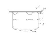
図1に示すように、本実施形態に係るレフィル容器1(以下、単に容器1ともいう)は、内容物を収容する内容器2と、内容器2を収容する外容器3と、内容器2を閉塞可能な蓋4と、を有している。しかし、容器1は、蓋4を有していなくても構わない。本実施形態では、内容器2は、内容物を使い切ったときなどに交換が可能なレフィル用の容器である。内容物は、クリーム状の化粧料等であってよいが、これに限定されない。また、内容物は、クリーム状のものに限定されず、固形状、粉状又は液状のもの等であってよい。本実施形態では、容器1は、広口の内容物の取出し口を有するとともに高さ方向に短いジャー容器として構成されているが、これに限定されない。例えば、容器1は、細口の内容物の取出し口を有するとともに高さ方向に長いボトル容器として構成されてもよい。 As shown in FIG. 1, the refill container 1 (hereinafter, also simply referred to as container 1) according to the present embodiment includes an
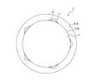
図2〜図3に示すように、内容器2は、円筒状の内周壁5と、内周壁5の上端に一体に連結する円環状のフランジ6と、内周壁5の下端を閉塞する内底壁7と、を有している。また、内周壁5とフランジ6とで内壁8が構成されている。内容器2は、例えば合成樹脂材料の射出成形によって形成された、一体成形品からなっている。しかし、内容器2は、合成樹脂製に限られず、またその製法も射出成形に限られない。また、内容器2は、複数の部材を組み付けることで構成してもよい。内周壁5の形状は円筒状に限られず、例えば、楕円筒状(横断面が楕円形の筒状)又は多角筒状(横断面が多角形の筒状)等であってもよい。フランジ6の形状は円環状に限られず、楕円環状(外縁が楕円形の環状)又は多角環状(外縁が多角形の環状)等であってもよい。また、フランジ6の形状は連続的な環状に限られず、間欠的な環状であってもよい。また、フランジ6は内周壁5の上端に代えて、例えば当該上端よりやや下方の部分に連結していてもよい。内底壁7は、径方向内側に向けて下方に傾斜しつつ肉厚が厚くなる略円錐形状をなしている。また、内底壁7は、内容器2を外容器3に取り付けた状態で、外容器3の外底壁12に当接するように構成されている(図5参照)。しかし、内底壁7の形状は、適宜変更が可能である。例えば、内底壁7は、底面視中央部のみが下方に突出し、当該突出部が外底壁12に当接可能な形状をなしていてもよい。 As shown in FIGS. 2 to 3, the
図2〜図3に示すように、内壁8は、周方向に全周に亘って等間隔で並ぶ5個の上凸部9と、5個の上凸部9の下方で当該5個の上凸部9と位置を揃えて周方向に並ぶ5個の嵌合凸部10と、を有している。上凸部9及び嵌合凸部10の個数は、5個に限られず、奇数個であればよい。その中でも、3個、5個又は7個が好ましい。5個の上凸部9は、フランジ6の外縁より内側で外容器3の外周壁11と上下方向に当接可能な凸状をなしている。また、5個の上凸部9は、フランジ6と内周壁5との連結部に設けられている。本実施形態では、各上凸部9は、下方に向けて径方向内側に傾斜する稜線を有する1つの突起からなっている。しかし、各上凸部9の形状は適宜変更が可能である。例えば、各上凸部9は、周方向に並ぶ2つ以上の突起からなっていてもよい。5個の嵌合凸部10は、内周壁5に設けられている。また、5個の嵌合凸部10は、外容器3の外周壁11と嵌合可能な凸状をなしている。本実施形態では、各嵌合凸部10は、周方向中央に向けて突出高さが徐々に増加する底面視三角形状をなしている(図3参照)。また、各嵌合凸部10は、径方向外側に向けて厚みが低減する先細形状をなしている(図2参照)。内壁8は、内容器2の取り付け状態において、5個の上凸部9及び5個の嵌合凸部10を除く部分が外容器3の外周壁11と接触しないように構成されている。 As shown in FIGS. 2 to 3, the
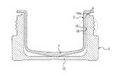
外容器3の形状は、内容器2の形状に合わせて設定される。或いは、内容器2の形状は、外容器3の形状に合わせて設定される。本実施形態では、図4に示すように、外容器3は、円筒状の外周壁11と、外周壁11の下端に連結する円板状の外底壁12と、を有している。しかし、外周壁11の形状は円筒状に限られず、例えば、楕円筒状(横断面が楕円形の筒状)又は多角筒状(横断面が多角形の筒状)等であってもよい。外底壁12の形状は、適宜変更が可能である。本実施形態では、外周壁11は、蓋4と係合可能な雄ねじ13を有する口部11aと、口部11aより拡径された外径を有する胴部11bとを有している。口部11aと蓋4とは、このような雄ねじ13によって互いに係合する構成に限られず、例えば互いに嵌合する構成としてもよい。本実施形態では、口部11aの外周面と胴部11bの上端面とにより、円環状の段部14が形成されている。また、口部11aの内周面は胴部11bの内周面に段差なく連続しており、口部11aの内径は胴部11bの内径と実質的に同一となっている。口部11aの内周面には、5個の嵌合凸部10と嵌合可能な円環状の嵌合部15が設けられている。嵌合部15は、本実施形態では、周方向に全周に亘って設けられた凸部からなっている。嵌合部15は、このような凸部に代えて、凹部又は段部からなっていてもよい。また、嵌合部15は、口部11aの内周面に代えて、胴部11bの内周面に設けてもよい。本実施形態では、外周壁11の上端面16には、該上端面16の外縁より内側で全周に亘って凸状をなす環状凸部16aが設けられている。5個の上凸部9は、当該環状凸部16aに当接可能である。本実施形態では、5個の上凸部9は、図1に示すように蓋4の取り付け状態において、環状凸部16aに当接することで、内容器2のそれ以上の沈み込みを阻止している。外容器3は、合成樹脂、金属、ガラス等の任意の材料からなる単一又は複数の部材によって構成することができる。 The shape of the outer container 3 is set according to the shape of the
外容器3の内側に内容器2を挿入し、図5〜図6に示すように、5個の嵌合凸部10に嵌合部15を下方へ乗り越えさせることにより、内容器2を外容器3に取り付けることができる。本実施形態では、内容器2を外容器3に取り付けた状態では、5個の上凸部9が環状凸部16aに当接し、内底壁7が外底壁12に当接している。しかし、内容器2を外容器3に取り付けた状態で5個の上凸部9が環状凸部16aに当接し、内底壁7が外底壁12に当接しない構成としてもよいし、内容器2を外容器3に取り付けた状態で5個の上凸部9が環状凸部16aに当接せず、内底壁7が外底壁12に当接する構成としてもよい。また、本実施形態では、5個の嵌合凸部10は、内容器2を外容器3に取り付けた状態で、内容器2の上方への移動を規制可能に、嵌合部15と嵌合している。しかし、5個の嵌合凸部10は、内容器2を外容器3に取り付けた状態で嵌合部15の下側に間隔を空けて位置するように構成されてもよい。 By inserting the
図1に示すように、蓋4は、口部11aの雄ねじ13と係合可能な雌ねじ17を有する円筒状の装着筒18aと、装着筒18aの上端を閉塞する天壁18bと、を有する蓋本体18を備えている。装着筒18aは、外容器3の段部14に配置されるように構成されており、胴部11bの外径と同一の外径を有している。しかし、蓋本体18の形状は適宜変更が可能である。また、蓋4は、天壁18bの下面に配置された円盤状のパッキン19を備えている。パッキン19は、蓋4の取り付け時にフランジ6に当接し、内容器2の開口部を閉塞する。パッキン19の形状又は配置は適宜変更が可能である。蓋4は、パッキン19を有していなくてもよい。蓋本体18は、合成樹脂、金属、ガラス等の任意の材料からなる単一又は複数の部材によって構成することができる。 As shown in FIG. 1, the lid 4 has a
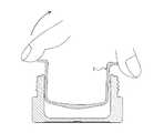
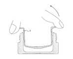
本実施形態に係るレフィル容器1は、例えば以下の要領によって、内容器2を外容器3から取り外すことができる。蓋4を取り外した状態で、使用者は、内容器2を外容器3から取り外すために、まず、内容器2のフランジ6の外縁を下方に押圧する。このとき、使用者が、図7に示すように、フランジ6の外縁における上凸部9側部分(すなわち、周方向において上凸部9が形成されている部分)を押圧した場合には、内周壁5の中心軸線を挟んだ当該押圧部の対向部分には嵌合凸部10がないため、当該対向部分における内周壁5の下部が外周壁11に近づくように内容器2が傾かせられて、嵌合部15と5個の嵌合凸部10との嵌合が解け、前記対向部分におけるフランジ6が浮き上がり、この浮き上がったフランジ6と外周壁11の上端面16との間の隙間が拡大する。したがって、図8に示すように、内容器2を容易に摘み上げることができる。一方、使用者が、図9に示すように、フランジ6の外縁における非上凸部9側部分(すなわち、周方向において上凸部9が形成されていない部分)を押圧した場合には、当該押圧部には上凸部9がないため、当該押圧部における内周壁5の上部が外周壁11に近づくように内容器2が傾かせられて、嵌合部15と5個の嵌合凸部10との嵌合が解け、内周壁5の中心軸線を挟んだ当該押圧部の対向部分におけるフランジ6が浮き上がり、この浮き上がったフランジ6と外周壁11の上端面16との間の隙間が拡大する。したがって、図10に示すように、内容器2を容易に摘み上げることができる。 In the refill container 1 according to the present embodiment, the
特に、本実施形態では、5個の上凸部9がフランジ6と内周壁5との連結部に設けられているので、フランジ6の外縁を押圧したときに内容器2を容易に傾かせることができる。また、本実施形態では、5個の上凸部9が環状凸部16aに当接可能であるので、フランジ6と外周壁11の上端面16との間の隙間を確保し易く、もって、内容器2の取り外しを容易にすることができる。 In particular, in the present embodiment, since the five upper
前記の説明は、本発明の一実施形態を示したものにすぎず、特許請求の範囲を限定するものではない。前記の実施形態は、本開示の基礎的事項に基づいて、例えば以下のような、種々の変更が可能である。 The above description merely shows one embodiment of the present invention, and does not limit the scope of claims. Based on the basic matters of the present disclosure, the above-described embodiment can be modified in various ways, for example, as follows.
前記の実施形態では、5個の上凸部9は、フランジ6と内周壁5との連結部に設けられている。しかし、5個の上凸部9は、フランジ6の下面、又は内周壁5の外周面に設けてもよい。また、前記の実施形態では、5個の上凸部9は、外周壁11の上端面16に設けられた環状凸部16aに当接可能に設けられている。しかし、5個の上凸部9は、環状凸部16aを有さない外周壁11の上端面16に当接可能に設けてもよい。 In the above embodiment, the five upper
また、前記の実施形態では、5個の上凸部9及び5個の嵌合凸部10は、内容器2の内壁8に設けられている。しかし、5個の上凸部9及び5個の嵌合凸部10は、外容器3の外周壁11に設けてもよい。この場合、例えば、外周壁11は、上端面16において周方向に全周に亘って等間隔で並ぶとともに、フランジ6の外縁より内側で内壁8(フランジ6)と上下方向に当接可能な凸状をなす、奇数個の上凸部と、外周壁11の内周面において、当該奇数個の上凸部の下方で当該奇数個の上凸部と位置を揃えて周方向に並ぶとともに、内壁8に設けられた環状の嵌合部と嵌合可能な凸状をなす、奇数個の嵌合凸部と、を有する構成とすることができる。 Further, in the above embodiment, the five upper
1 レフィル容器
2 内容器
3 外容器
4 蓋
5 内周壁
6 フランジ
7 内底壁
8 内壁
9 上凸部
10 嵌合凸部
11 外周壁
11a 口部
11b 胴部
12 外底壁
13 雄ねじ
14 段部
15 嵌合部
16 外周壁の上端面
16a 環状凸部
17 雌ねじ
18 蓋本体
18a 装着筒
18b 天壁
19 パッキン1
Claims (3)
Translated fromJapanese外周壁と外底壁とを有する外容器と、を備え、
前記内容器は、前記外周壁の内側に配置される内周壁と、該内周壁に連結するとともに前記外周壁の上側に配置されるフランジと、を有する内壁と、内底壁と、を備え、
前記内壁及び前記外周壁の一方は、
周方向に全周に亘って等間隔で並ぶとともに、前記フランジの外縁より内側で前記内壁及び前記外周壁の他方と上下方向に当接可能な凸状をなす、奇数個の上凸部と、
前記奇数個の上凸部の下方で該奇数個の上凸部と位置を揃えて周方向に並ぶとともに、前記内壁及び前記外周壁の前記他方と嵌合可能な凸状をなす、奇数個の嵌合凸部と、を有し、
前記内底壁は、前記内容器を前記外容器に取り付けた状態で前記外底壁に当接せず、又は底面視中央部のみにおいて当接し、
前記嵌合凸部の個数は3個、5個又は7個であり、各嵌合凸部は周方向中央に向けて突出高さが徐々に増加する、
レフィル容器。An inner container to store the contents and
With an outer container having an outer peripheral walland an outer bottom wall,
The inner container includes an inner wall having an inner peripheral wall arranged inside the outer peripheral wall, a flange connected to the inner peripheral wall and arranged above the outer peripheral wall, and an innerbottom wall .
One of the inner wall and the outer peripheral wall
An odd number of upper convex portions that are lined up at equal intervals over the entire circumference in the circumferential direction and have a convex shape that can come into contact with the other of the inner wall and the outer peripheral wall in the vertical direction inside the outer edge of the flange.
An odd number of convex portions that are aligned with the odd number of upper convex portions below the odd number of upper convex portions and are aligned in the circumferential direction, and have a convex shape that can be fitted with the other of the inner wall and the outer peripheral wall.possess and the convex portion, the,
The inner bottom wall does not abut on the outer bottom wall with the inner container attached to the outer container, or abuts only at the center of the bottom view.
The number of the fitting protrusions is 3, 5, or 7, and the protrusion height of each fitting protrusion gradually increases toward the center in the circumferential direction.
Refill container.
前記奇数個の上凸部は、前記環状凸部に当接可能である、請求項1又は2に記載のレフィル容器。The upper end surface of the outer peripheral wall is provided with an annular convex portion forming a convex shape over the entire circumference inside the outer edge of the upper end surface.
The refill container according to claim 1 or 2, wherein the odd number of upper convex portions can come into contact with the annular convex portion.
Priority Applications (1)
| Application Number | Priority Date | Filing Date | Title |
|---|---|---|---|
| JP2017230174AJP6925744B2 (en) | 2017-11-30 | 2017-11-30 | Refill container |
Applications Claiming Priority (1)
| Application Number | Priority Date | Filing Date | Title |
|---|---|---|---|
| JP2017230174AJP6925744B2 (en) | 2017-11-30 | 2017-11-30 | Refill container |
Publications (2)
| Publication Number | Publication Date |
|---|---|
| JP2019099186A JP2019099186A (en) | 2019-06-24 |
| JP6925744B2true JP6925744B2 (en) | 2021-08-25 |
Family
ID=66975720
Family Applications (1)
| Application Number | Title | Priority Date | Filing Date |
|---|---|---|---|
| JP2017230174AActiveJP6925744B2 (en) | 2017-11-30 | 2017-11-30 | Refill container |
Country Status (1)
| Country | Link |
|---|---|
| JP (1) | JP6925744B2 (en) |
Families Citing this family (4)
| Publication number | Priority date | Publication date | Assignee | Title |
|---|---|---|---|---|
| KR102281200B1 (en)* | 2020-04-06 | 2021-07-26 | 주식회사 신우 | Cosmetic container for easy to change refill case |
| WO2022049649A1 (en)* | 2020-09-01 | 2022-03-10 | 株式会社資生堂 | Container, method for manufacturing container, and double container |
| WO2025142501A1 (en)* | 2023-12-26 | 2025-07-03 | 株式会社資生堂 | Double container, refill container, and method for manufacturing refill container |
| KR102811211B1 (en)* | 2024-02-23 | 2025-06-04 | 주식회사 영광산업 | metal cosmetic container with improved the recyclability |
Family Cites Families (4)
| Publication number | Priority date | Publication date | Assignee | Title |
|---|---|---|---|---|
| DE9317521U1 (en)* | 1993-11-16 | 1994-01-27 | Bramlage GmbH, 49393 Lohne | Cream jar |
| JP3930630B2 (en)* | 1998-02-13 | 2007-06-13 | エム・エフ・ヴィ株式会社 | Refill container |
| JP5553263B2 (en)* | 2010-05-28 | 2014-07-16 | 三洋化学工業株式会社 | Removable container |
| JP5887649B2 (en)* | 2011-05-24 | 2016-03-16 | 三洋化学工業株式会社 | Removable container |
- 2017
- 2017-11-30JPJP2017230174Apatent/JP6925744B2/enactiveActive
Also Published As
| Publication number | Publication date |
|---|---|
| JP2019099186A (en) | 2019-06-24 |
Similar Documents
| Publication | Publication Date | Title |
|---|---|---|
| JP6925744B2 (en) | Refill container | |
| US10799007B2 (en) | Container for a cosmetic product and assembly method | |
| CN1089710C (en) | Airtight container and cover structure | |
| CN113226940A (en) | Safety cap bottle assembly | |
| JP4919877B2 (en) | Double container | |
| JP6833279B2 (en) | Inner container with cap | |
| JP6463836B2 (en) | Container cap assembly | |
| JP6706537B2 (en) | Double container with refill container | |
| CN115844132A (en) | Cosmetic product dispensing bottle with stacked base, refill and cap | |
| CA3031871C (en) | A container including a cap having a tamper evident band | |
| JP6570342B2 (en) | Spherical container | |
| JP6660765B2 (en) | Thin container with dispenser | |
| JP6876474B2 (en) | Synthetic resin container lid | |
| JP2023173787A (en) | Replacement container | |
| JP2017065723A5 (en) | ||
| JP6895862B2 (en) | Fixed-quantity discharge container | |
| US2832491A (en) | Vacuum bottle | |
| JP6821262B2 (en) | container | |
| US20040040985A1 (en) | Medicament dispensing container closure assembly | |
| JP6377014B2 (en) | Double container | |
| JP2020138794A (en) | Changeable container | |
| JP7305288B2 (en) | powder container | |
| JP7330861B2 (en) | Caps and containers with caps | |
| JP6861097B2 (en) | Modeling container | |
| JP6746221B2 (en) | Replacement container |
Legal Events
| Date | Code | Title | Description |
|---|---|---|---|
| A621 | Written request for application examination | Free format text:JAPANESE INTERMEDIATE CODE: A621 Effective date:20200605 | |
| A977 | Report on retrieval | Free format text:JAPANESE INTERMEDIATE CODE: A971007 Effective date:20210513 | |
| A131 | Notification of reasons for refusal | Free format text:JAPANESE INTERMEDIATE CODE: A131 Effective date:20210525 | |
| A521 | Written amendment | Free format text:JAPANESE INTERMEDIATE CODE: A523 Effective date:20210713 | |
| TRDD | Decision of grant or rejection written | ||
| A01 | Written decision to grant a patent or to grant a registration (utility model) | Free format text:JAPANESE INTERMEDIATE CODE: A01 Effective date:20210803 | |
| A61 | First payment of annual fees (during grant procedure) | Free format text:JAPANESE INTERMEDIATE CODE: A61 Effective date:20210803 | |
| R150 | Certificate of patent or registration of utility model | Ref document number:6925744 Country of ref document:JP Free format text:JAPANESE INTERMEDIATE CODE: R150 |