JP6922082B2 - Management of transfer function judgment of measurement sensor - Google Patents
Management of transfer function judgment of measurement sensorDownload PDFInfo
- Publication number
- JP6922082B2 JP6922082B2JP2020511462AJP2020511462AJP6922082B2JP 6922082 B2JP6922082 B2JP 6922082B2JP 2020511462 AJP2020511462 AJP 2020511462AJP 2020511462 AJP2020511462 AJP 2020511462AJP 6922082 B2JP6922082 B2JP 6922082B2
- Authority
- JP
- Japan
- Prior art keywords
- monitoring
- transfer function
- profile
- measurement sensor
- monitoring module
- Prior art date
- Legal status (The legal status is an assumption and is not a legal conclusion. Google has not performed a legal analysis and makes no representation as to the accuracy of the status listed.)
- Active
Links
Images


Classifications
- G—PHYSICS
- G01—MEASURING; TESTING
- G01R—MEASURING ELECTRIC VARIABLES; MEASURING MAGNETIC VARIABLES
- G01R27/00—Arrangements for measuring resistance, reactance, impedance, or electric characteristics derived therefrom
- G01R27/28—Measuring attenuation, gain, phase shift or derived characteristics of electric four pole networks, i.e. two-port networks; Measuring transient response
- G—PHYSICS
- G01—MEASURING; TESTING
- G01R—MEASURING ELECTRIC VARIABLES; MEASURING MAGNETIC VARIABLES
- G01R11/00—Electromechanical arrangements for measuring time integral of electric power or current, e.g. of consumption
- G01R11/02—Constructional details
- G01R11/25—Arrangements for indicating or signalling faults
- G—PHYSICS
- G01—MEASURING; TESTING
- G01R—MEASURING ELECTRIC VARIABLES; MEASURING MAGNETIC VARIABLES
- G01R11/00—Electromechanical arrangements for measuring time integral of electric power or current, e.g. of consumption
- G01R11/56—Special tariff meters
- G—PHYSICS
- G01—MEASURING; TESTING
- G01R—MEASURING ELECTRIC VARIABLES; MEASURING MAGNETIC VARIABLES
- G01R15/00—Details of measuring arrangements of the types provided for in groups G01R17/00 - G01R29/00, G01R33/00 - G01R33/26 or G01R35/00
- G01R15/04—Voltage dividers
- G—PHYSICS
- G01—MEASURING; TESTING
- G01R—MEASURING ELECTRIC VARIABLES; MEASURING MAGNETIC VARIABLES
- G01R21/00—Arrangements for measuring electric power or power factor
- G01R21/007—Adapted for special tariff measuring
- G—PHYSICS
- G01—MEASURING; TESTING
- G01R—MEASURING ELECTRIC VARIABLES; MEASURING MAGNETIC VARIABLES
- G01R21/00—Arrangements for measuring electric power or power factor
- G01R21/133—Arrangements for measuring electric power or power factor by using digital technique
- G01R21/1333—Arrangements for measuring electric power or power factor by using digital technique adapted for special tariff measuring
- G—PHYSICS
- G01—MEASURING; TESTING
- G01R—MEASURING ELECTRIC VARIABLES; MEASURING MAGNETIC VARIABLES
- G01R35/00—Testing or calibrating of apparatus covered by the other groups of this subclass
- G01R35/04—Testing or calibrating of apparatus covered by the other groups of this subclass of instruments for measuring time integral of power or current
Landscapes
- Physics & Mathematics (AREA)
- General Physics & Mathematics (AREA)
- Engineering & Computer Science (AREA)
- Power Engineering (AREA)
- Measuring Instrument Details And Bridges, And Automatic Balancing Devices (AREA)
- Remote Monitoring And Control Of Power-Distribution Networks (AREA)
- Supply And Distribution Of Alternating Current (AREA)
- Arrangements For Transmission Of Measured Signals (AREA)
Description
Translated fromJapanese本開示は、測定センサの伝達関数の判定を管理するための、機器、方法およびシステムに関する。 The present disclosure relates to devices, methods and systems for managing the determination of the transfer function of a measurement sensor.
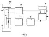
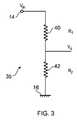
ユーティリティメーターは、ユーザ(例えば、世帯ユーザまたは事業ユーザなど)によって消費されているユーティリティ(電気など)の量を測定する。ユーティリティメーターが電気使用量を測定するように構成されている場合(電気消費メータ)、電気消費量を測定するための技術は、少なくとも1つの(例えば、抵抗シャントおよび/または変流器を含んでもよい)電流測定装置を利用した電流の測定および/または、(例えば、分圧器を含んでもよい)電圧測定装置を利用した電圧の測定を含み、それを利用することで消費電力およびエネルギーが判定されてもよい。 A utility meter measures the amount of utility (such as electricity) consumed by a user (eg, household user or business user). If the utility meter is configured to measure electricity usage (electricity consumption meter), the technique for measuring electricity consumption may include at least one (eg, a resistor shunt and / or a currentizer). Includes current measurement using a (good) current measuring device and / or voltage measurement using a voltage measuring device (eg, including a voltage divider), which can be used to determine power consumption and energy. You may.
しかしながら、電流測定装置(複数可)および/または電圧測定装置(複数可)の変更は、電流および/または電圧の測定の精度不良ならびに、結果として消費電力およびエネルギーの判定の精度不良をもたらし得る。例えば、電流測定装置および/または電圧測定装置の精度が摩耗および経年変化により経時的にずれ得るか、または、ユーティリティメーターが不良に陥り、それによって、電流測定装置および/または電圧測定装置が不正確な測定値を提示し得るか、または、ユーティリティ料金を削減することを試みるなどのために、不正なユーザが何らかの方法で電流測定装置および/または電圧測定装置に手を加え得る。消費者およびユーティリティプロバイダの両方のために、ユーティリティ消費量が正確に、かつ整合的に測定されることを確実にするべく、あらゆる種類の精度不良を識別し、調査することが可能となるようにユーティリティメーターの精度を監視したいという要望が存在する。 However, changes in the current and / or voltage measuring device (s) can result in poor accuracy in measuring current and / or voltage and, as a result, inaccurate determination of power consumption and energy. For example, the accuracy of the current and / or voltage measuring device may shift over time due to wear and aging, or the utility meter may fail, causing the current and / or voltage measuring device to become inaccurate. Unauthorized users may somehow modify the current and / or voltage measuring devices in order to be able to present good measurements or to try to reduce utility charges. To be able to identify and investigate all kinds of inaccuracies to ensure that utility consumption is measured accurately and consistently for both consumers and utility providers. There is a desire to monitor the accuracy of utility meters.
測定装置の特性を監視して、それらの精度を監視することが可能である。例えば、電流測定装置または電圧測定装置などの、測定装置の伝達関数の推定値(センササイズ、またはゲイン、またはCCの推定値とも称される)および、各々の推定された伝達関数の確信値(すなわち、伝達関数の推定値の期待されている精度を定量化する値)が経時的に判定され得る。測定装置の精度の変化を識別するために、これらの値の経時的な変化(例えば、センサドリフトによる、または、タンパまたは試みられたタンパイベントによる変化など)が利用され得る。 It is possible to monitor the characteristics of the measuring device and monitor their accuracy. Estimates of the transfer function of the measuring device, such as a current or voltage measuring device (also referred to as sensor size, or gain, or CC estimate) and confidence in each estimated transfer function (also referred to as an estimate of the sensor size, or gain, or CC). That is, a value that quantifies the expected accuracy of the estimated value of the transfer function) can be determined over time. Changes over time in these values (eg, due to sensor drift, or due to a tamper or attempted tamper event, etc.) can be utilized to identify changes in the accuracy of the measuring device.
しかしながら、測定装置の精度を確実に監視するために、伝達関数および対応する確信値の推定値は極めて規則的に(例えば、秒単位でなどの、秒レベルで)判定する必要があり得る。これは特に、非常に短い時間しか続かない可能性がある、タンパまたは試みられたタンパイベントの識別に関して重要であり得る。このような大量のデータの判定、処理および解釈は、特に、比較的低い計算能力、記憶容量および通信帯域を典型的には有し得るユーティリティメーターにとって、重要な課題を示し得る。 However, in order to reliably monitor the accuracy of the measuring device, the transfer function and corresponding belief value estimates may need to be determined very regularly (eg, at the second level, such as in seconds). This can be particularly important with respect to identifying tampers or attempted tampa events, which can last only a very short time. Determining, processing and interpreting such large amounts of data can present significant challenges, especially for utility meters that may typically have relatively low computational power, storage capacity and communication bandwidth.
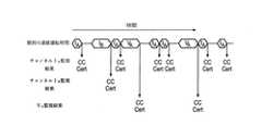
本開示の第1の態様において、電気的測定システムで使用するためのマネージャ機器であって、電気的測定システムが、第1の電気的特性を測定するための第1の測定センサおよび、第1の測定センサの伝達関数の推定値を判定するように構成された監視モジュールを含み、第1の個別の連続運転時間に亘る第1の測定センサの伝達関数の推定値を判定するように監視モジュールに命令するための第1の制御命令を出力することと、第1の監視結果を監視モジュールから取得することであって、監視結果が第1の測定センサ(例えば、第1の測定センサに関する「CC」)の伝達関数の推定値を含む、取得することと、第1の監視結果に少なくとも部分的に基づいて、報告を生成することと、を行うように構成されている、マネージャ機器が提供される。 In the first aspect of the present disclosure, a manager device for use in an electrical measurement system, wherein the electrical measurement system has a first measurement sensor for measuring a first electrical characteristic and a first measurement sensor. Includes a monitoring module configured to determine the transmission function estimate of the measurement sensor of, and a monitoring module to determine the transmission function estimate of the first measurement sensor over the first individual continuous operating time. Is to output the first control command for instructing the first measurement sensor and to acquire the first monitoring result from the monitoring module, and the monitoring result is related to the first measurement sensor (for example, the "first measurement sensor". Provided by the manager device, which is configured to include and obtain estimates of the transfer function of CC ") and to generate a report based at least in part on the first monitoring result. Will be done.
好ましくは、第1の監視結果が、第1のセンサの伝達関数の推定値の精度を示す確信値(例えば、「Cert」)をさらに含む。 Preferably, the first monitoring result further comprises a certainty value (eg, "Cert") indicating the accuracy of the transfer function estimate of the first sensor.
第1の制御命令は、第1の個別の連続運転時間の開始時間および/または第1の個別の連続運転時間の持続時間および/または、第1の監視結果の判定において利用される電力モードのうちの少なくとも1つを制御するように構成されてもよい。 The first control command is the start time of the first individual continuous operation time and / or the duration of the first individual continuous operation time and / or the power mode used in determining the first monitoring result. It may be configured to control at least one of them.
電気的測定システムは、電気的測定システムが第2の電気的特性を測定するための第2の測定センサをさらに含んでもよく、監視モジュールが第2の測定センサの伝達関数の推定値を判定するようにさらに構成され、マネージャ機器が、第2の個別の連続運転時間に亘る第2の測定センサの伝達関数の推定値を判定するように監視モジュールに命令するための第2の制御命令を出力することと、第2の監視結果を第2の監視結果を監視モジュールから取得することであって、第2の監視結果が第2の測定センサの伝達関数の推定値を含む、取得することと、第1の監視結果および第2の監視結果に少なくとも部分的に基づいて、報告を生成することと、を行うようにさらに構成されている。 The electrical measurement system may further include a second measurement sensor for the electrical measurement system to measure the second electrical characteristic, and the monitoring module determines an estimate of the transfer function of the second measurement sensor. The manager device outputs a second control command for instructing the monitoring module to determine an estimate of the transmission function of the second measurement sensor over the second individual continuous operation time. To obtain the second monitoring result and to acquire the second monitoring result from the monitoring module, and the second monitoring result includes the estimated value of the transmission function of the second measurement sensor. It is further configured to generate reports based on, at least in part, the first and second monitoring results.
第2の制御命令が、第2の個別の連続運転時間の開始時間および/または第2の個別の連続運転時間の持続時間および/または第2の監視結果の判定において利用される電力モードのうちの少なくとも1つを制御するように構成されてもよい。 Of the power modes in which the second control command is used to determine the start time of the second individual continuous operation time and / or the duration of the second individual continuous operation time and / or the second monitoring result. It may be configured to control at least one of.
マネージャ機器は、1つ以上のさらなる個別の連続運転時間に亘る第1の測定センサの伝達関数の1つ以上のさらなる推定値を判定するように監視モジュールに命令するための、1つ以上のさらなる制御命令を出力することと、1つ以上のさらなる監視結果を監視モジュールから取得することであって、各々のさらなる監視結果が第1の測定センサの伝達関数のさらなる推定値のうちの1つを含む、取得することと、第1の監視結果および取得された1つ以上のさらなる監視結果に少なくとも部分的に基づいて、報告を生成することと、を行うようにさらに構成されてもよい。 The manager device has one or more additional units for instructing the monitoring module to determine one or more additional estimates of the transfer function of the first measurement sensor over one or more additional individual continuous operation times. Outputting a control command and obtaining one or more further monitoring results from the monitoring module, each further monitoring result providing one of the further estimates of the transfer function of the first measurement sensor. It may be further configured to include, obtain, and generate a report, at least in part, based on the first monitoring result and one or more additional monitoring results obtained.
1つ以上のさらなる制御命令は、1つ以上のさらなる個別の連続運転時間の各々の開始時間および/または、1つ以上のさらなる個別の連続運転時間の各々の持続時間および/または、第1の測定センサの伝達関数の1つ以上の推定値の各々の判定において利用される電力モードのうちの少なくとも1つを制御するように構成されている。 One or more additional control commands are each start time of one or more additional individual continuous operation times and / or each duration and / or first of one or more additional individual continuous operation times. It is configured to control at least one of the power modes used in each determination of one or more estimates of the transfer function of the measurement sensor.
マネージャ機器は、静的監視設定に少なくとも部分的に基づいて、第1の制御命令を判定するようにさらに構成されてもよい。静的監視設定は、伝達関数が監視される1つ以上の測定センサを示す関心チャンネルの設定、第1のセンサの伝達関数の推定値のために達成される精度の目標最小レベルを示すチャンネル優先度設定、伝達関数の判定における監視モジュールのための電力消費の所望のレベルを示す電力消費設定、個別の連続運転時間に関する最小時間を示す最小連続運転時間設定、個別の連続運転時間に関する最大時間を示す最大連続運転時間設定のうちの少なくとも1つを含んでもよい。 The manager device may be further configured to determine the first control instruction, at least in part, based on the static monitoring settings. The static monitoring setting is the setting of the channel of interest indicating one or more measurement sensors whose transmission function is monitored, the channel priority indicating the target minimum level of accuracy achieved for the transmission function estimate of the first sensor. Degree setting, power consumption setting indicating the desired level of power consumption for the monitoring module in determining the transfer function, minimum continuous operation time setting indicating the minimum time for individual continuous operation time, maximum time for individual continuous operation time. It may include at least one of the maximum continuous operation time settings shown.
好ましくは、マネージャ機器が、1つ以上の以前判定された監視結果に少なくとも部分的に基づいて、第1の制御命令を判定するようにさらに構成されており、1つ以上の以前判定された監視結果の各々が第1のセンサの伝達関数の推定値を含む。1つ以上の以前判定された監視結果の各々は、第1のセンサの伝達関数の推定値の精度を示す確信値をさらに含んでもよい。 Preferably, the manager device is further configured to determine the first control instruction based on at least partly based on one or more previously determined monitoring results, and one or more previously determined monitoring. Each of the results contains an estimate of the transfer function of the first sensor. Each of the one or more previously determined monitoring results may further include a confidence value indicating the accuracy of the transfer function estimate of the first sensor.
マネージャ機器は、報告を定期的に生成するようにさらに構成されてもよい。マネージャ機器は、先行する報告時間の間に取得された監視結果に少なくとも部分的に基づいて、定期的な報告を生成するように構成されてもよい。 The manager device may be further configured to generate reports on a regular basis. The manager device may be configured to generate periodic reports based at least in part on the monitoring results acquired during the preceding reporting time.
追加的に、または代替的に、マネージャ機器は、第1の監視結果がアラート条件を満たすか否かを判定し、第1の監視結果がアラート条件を満たす場合に、第1の監視結果に少なくとも部分的に基づいて報告を生成するようにさらに構成されてもよい。アラート条件はアラート閾値を含んでもよく、第1の測定センサの伝達関数の推定値とベンチマーク伝達関数値との間の差異がアラート閾値を超える場合に、アラート条件が満たされる。 Additionally or additionally, the manager device determines whether the first monitoring result satisfies the alert condition, and if the first monitoring result satisfies the alert condition, at least the first monitoring result is satisfied. It may be further configured to generate reports on a partial basis. The alert condition may include an alert threshold, and the alert condition is satisfied when the difference between the estimated value of the transfer function of the first measurement sensor and the benchmark transfer function value exceeds the alert threshold.
マネージャ機器は、通信ネットワークを介してユーティリティネットワークエンティティとインターフェースするための通信モジュールをさらに含んでもよく、マネージャ機器は、通信モジュールを介して、ユーティリティネットワークエンティティに通信の報告を出力するようにさらに構成されている。 The manager device may further include a communication module for interfacing with the utility network entity over the communication network, and the manager device is further configured to output a communication report to the utility network entity via the communication module. ing.
電気的測定システムは、通信ネットワークを介してユーティリティネットワークエンティティとインターフェースするための通信モジュールをさらに含んでもよく、マネージャ機器は、通信モジュールを介してユーティリティネットワークエンティティからオンデマンド報告要求を受信し、通信モジュールを介して、ユーティリティネットワークエンティティに、通信の報告を出力するようにさらに構成されている。マネージャ機器は、ユーティリティネットワークエンティティからのオンデマンド報告要求の受信後に、第1の監視結果に少なくとも部分的に基づいて報告を生成するようにさらに構成されてもよい。 The electrical measurement system may further include a communication module for interfacing with the utility network entity over the communication network, and the manager device receives an on-demand reporting request from the utility network entity via the communication module and the communication module. It is further configured to output communication reports to utility network entities via. The manager device may be further configured to generate a report based at least in part on the first monitoring result after receiving the on-demand report request from the utility network entity.
オンデマンド報告要求はオンデマンド報告設定を含んでもよく、マネージャ機器は、第1の監視結果およびオンデマンド報告設定に少なくとも部分的に基づいて報告を生成するようにさらに構成されている。オンデマンド報告設定は、報告が関連するべき期間を示すオンデマンド報告期間識別子、および/または、報告が有すべきデータサイズを示すオンデマンド報告長識別子のうちの少なくとも1つを含んでもよい。 The on-demand reporting request may include an on-demand reporting setting, and the manager device is further configured to generate a report based at least in part on the first monitoring result and the on-demand reporting setting. The on-demand reporting settings may include at least one of an on-demand reporting period identifier indicating the period for which the report should be relevant and / or an on-demand reporting length identifier indicating the data size that the report should have.
報告のデータサイズは、それが基づく監視結果の組み合わせられたデータサイズより小さくてもよい(例えば、報告が監視結果の組み合わせられたサイズよりも小さいデータサイズを有するように、報告が監視結果から導出されてもよい)。 The data size of the report may be smaller than the combined data size of the monitoring results on which it is based (eg, the report derives from the monitoring results so that the report has a smaller data size than the combined size of the monitoring results. May be done).
代替的に、報告はそれが基づく監視結果を含んでもよく、この場合、報告のデータサイズは、監視結果の組み合わせられたデータサイズよりも小さくなくてもよい。 Alternatively, the report may include monitoring results on which it is based, in which case the data size of the report may not be smaller than the combined data size of the monitoring results.
本開示の第2の態様において、少なくとも1つの電気的特性を測定するための電気的測定システムが提供され、電気的測定システムは、第1の電気的特性を測定するための第1の測定センサ、第1の測定センサの伝達関数の推定値を判定するように構成された監視モジュール、および、第1の個別の連続運転時間に亘る第1の測定センサの伝達関数の推定値を判定するように監視モジュールに命令するための第1の制御命令を出力することと、監視モジュールから第1の監視結果を取得することであって、第1の監視結果が、第1の測定センサの伝達関数の第1の推定値を含む、取得することと、第1の監視結果に少なくとも部分的に基づいて、報告を生成することと、を行うように構成されたマネージャ機器を含む。電気的測定システムは、ユーティリティメーターであってもよい。 In the second aspect of the present disclosure, an electrical measuring system for measuring at least one electrical characteristic is provided, wherein the electrical measuring system is a first measuring sensor for measuring the first electrical characteristic. , A monitoring module configured to determine the transmission function estimates of the first measurement sensor, and to determine the transmission function estimates of the first measurement sensor over the first individual continuous operating time. Is to output the first control command for instructing the monitoring module and to acquire the first monitoring result from the monitoring module, and the first monitoring result is the transmission function of the first measurement sensor. Includes a manager device configured to perform, including a first estimate of, and generating a report, at least in part, based on the first monitoring result. The electrical measurement system may be a utility meter.
電気的測定システムは、通信ネットワークを介してユーティリティネットワークエンティティとインターフェースするための通信モジュールをさらに含んでもよく、マネージャ機器は、通信モジュールを介して、ユーティリティネットワークエンティティに通信の報告を出力するようにさらに構成されている。 The electrical measurement system may further include a communication module for interfacing with the utility network entity over the communication network, and the manager device may further include a communication report to the utility network entity via the communication module. It is configured.
本開示の第3の態様において、第1の電気的特性を測定するための第1の測定センサの伝達関数の判定の管理方法が提供され、本方法は、第1の個別の連続運転時間に亘る第1の測定センサの伝達関数の推定値を判定するように監視モジュールに命令することと、監視モジュールから第1の監視結果を取得することであって、第1の監視結果が第1の測定センサの伝達関数の第1の推定値を含む、取得することと、第1の監視結果に少なくとも部分的に基づいて、報告を生成することと、を含む。 In a third aspect of the present disclosure, a method of managing the determination of the transfer function of a first measurement sensor for measuring a first electrical characteristic is provided, the method of which is set to a first individual continuous operating time. Instructing the monitoring module to determine the estimated value of the transfer function of the first measurement sensor over and over, and obtaining the first monitoring result from the monitoring module, the first monitoring result is the first. It includes obtaining, including a first estimate of the transfer function of the measurement sensor, and generating a report, at least in part, based on the first monitoring result.
本開示の第4の態様において、1つ以上のプロセッサに、第3の態様の方法を実行させるためのプログラムを格納する非一時的なコンピュータ可読媒体が提供される。 In a fourth aspect of the present disclosure, a non-transitory computer-readable medium is provided that stores a program for causing one or more processors to perform the method of the third aspect.
本開示の第5の態様において、1つ以上のプロセッサに第3の態様の方法を実行させるように構成されたファームウェアモジュールが提供される。 In a fifth aspect of the present disclosure, there is provided a firmware module configured to cause one or more processors to perform the method of the third aspect.
以下のさらなる態様もまた、開示される。
電気的測定システムの監視モジュールの運転を制御するためのコントローラ機器であって、コントローラ機器が、複数の監視モジュール運転状態のうちの1つを選択し、監視モジュールの運転を制御するための制御動作を行って選択された監視モジュール運転状態を実現するように構成され、複数の監視モジュール運転状態が、a)第1の測定センサの伝達関数の推定値(例えば、「CC」)および、第1の測定センサの伝達関数の推定値の精度を示す、対応する確信値(例えば、「Cert」)を含む第1の監視結果を判定するために、少なくともユーティリティメーターの第1の測定センサを監視する、と、b)電気的測定システムのいかなる測定センサも監視しない、を含み、第1の測定センサが第1の電気的特性を測定するためにある。The following additional aspects are also disclosed.
A controller device for controlling the operation of the monitoring module of the electrical measurement system, and the controller device selects one of a plurality of monitoring module operating states and controls the operation of the monitoring module. To achieve the selected monitoring module operating state, a) the estimated value of the transmission function of the first measurement sensor (eg, "CC") and the first monitoring module operating state. Monitor at least the first measurement sensor of the utility meter to determine the first monitoring result, including the corresponding confidence value (eg, "Cert"), which indicates the accuracy of the transmission function estimate of the measurement sensor. , And b) do not monitor any measuring sensor of the electrical measuring system, the first measuring sensor is for measuring the first electrical characteristic.
監視モジュール運転状態a)が選択される場合に、制御動作は、第1の個別の連続運転時間の間、第1の測定センサを監視して、第1の監視結果を判定するために、第1の制御命令を監視モジュールに通信することを含んでもよい。 When the monitoring module operating state a) is selected, the control operation is to monitor the first measurement sensor during the first individual continuous operation time to determine the first monitoring result. It may include communicating the control command of 1 to the monitoring module.
第1の個別の連続運転時間は、固定時間長または可変時間長であってもよい。 The first individual continuous operation time may be a fixed time length or a variable time length.
第1の個別の連続運転時間が可変時間長である場合に、コントローラ機器は、第1の個別の連続運転時間を判定するように構成されてもよい。好ましくは、第1のセンサの伝達関数のそれぞれの1つ以上の以前判定された推定値に対応する、1つ以上の以前判定された確信値に少なくとも部分的に基づいて、第1の個別の連続運転時間を判定するように、コントローラ機器が構成されている。第1のセンサの伝達関数のそれぞれの1つ以上の以前判定された推定値に対応する、1つ以上の以前判定された確信値を目標確信値と比較することによって、第1の測定センサの伝達関数の推定値に関する精度の所望のレベルを達成するために、第1の個別の連続運転時間を判定するように、コントローラ機器が構成されてもよい。 When the first individual continuous operation time is a variable time length, the controller device may be configured to determine the first individual continuous operation time. Preferably, the first individual is at least partially based on one or more previously determined confidence values corresponding to each one or more previously determined estimates of the transfer function of the first sensor. The controller device is configured to determine the continuous operation time. By comparing one or more previously determined confidence values corresponding to each one or more previously determined estimates of the transfer function of the first sensor with the target confidence values, the first measurement sensor The controller equipment may be configured to determine the first individual continuous operation time in order to achieve the desired level of accuracy with respect to the transfer function estimates.
1つ以上の以前判定された確信値が目標確信値を達成できない場合に、第1の測定センサの伝達関数の1つ以上の以前判定された推定値の判定において利用された1つ以上の個別の連続運転時間を上回るように第1の個別の連続運転時間が設定されてもよい。1つ以上の以前判定された確信値が目標確信値を超える場合に、第1の測定センサの伝達関数の1つ以上の以前判定された推定値の判定において利用された1つ以上の個別の連続運転時間を下回るように、第1の個別の連続運転時間が設定されてもよい。 One or more individual used in determining one or more previously determined estimates of the transfer function of the first measurement sensor when one or more previously determined confidence values fail to achieve the target confidence value. The first individual continuous operation time may be set so as to exceed the continuous operation time of. One or more individual individuals used in determining one or more previously determined estimates of the transfer function of the first measurement sensor when one or more previously determined confidence values exceed the target confidence values. The first individual continuous operation time may be set to be less than the continuous operation time.
好ましくは、第1の測定センサの伝達関数のそれぞれの1つ以上の以前判定された推定値に対応する、1つ以上の以前判定された確信値に少なくとも部分的に基づいて、複数の監視モジュール運転状態のうちの1つを選択するように、コントローラ機器がさらに構成されている。 Preferably, a plurality of monitoring modules are based, at least in part, on one or more previously determined confidence values corresponding to each one or more previously determined estimates of the transfer function of the first measurement sensor. The controller device is further configured to select one of the operating conditions.
好ましくは、監視時間窓の間に第1の測定センサに関する監視結果を判定する監視モジュールによって費やされる時間の比率が、監視時間窓の間に監視モジュールによって判定される第1の測定センサの伝達関数の推定値が精度の所望のレベルを達成するために十分であるように、複数の監視モジュール運転状態のうちの1つを選択するように、コントローラ機器がさらに構成されている。 Preferably, the ratio of the time spent by the monitoring module to determine the monitoring result for the first measurement sensor during the monitoring time window is the transfer function of the first measuring sensor determined by the monitoring module during the monitoring time window. The controller device is further configured to select one of a plurality of monitoring module operating states so that the estimated value of is sufficient to achieve the desired level of accuracy.
1つ以上の以前判定された確信値に基づいて第1の利用目標を判定することであって、第1の測定センサに関する監視結果を判定する監視モジュールによって費やされる監視時間窓の目標合計比率第1の利用目標が示す、判定することと、第1の利用目標に少なくとも部分的に基づいて、複数の監視運転状態のうちの1つを選択することによって、複数の監視運転状態のうちの1つを選択するように、コントローラ機器が構成されてもよい。 The first utilization target is determined based on one or more previously determined confidence values, and the target total ratio of the monitoring time window spent by the monitoring module that determines the monitoring result for the first measurement sensor. One of a plurality of monitoring operation states by selecting one of the plurality of monitoring operation states based on the determination indicated by the utilization target of 1 and at least partially based on the first utilization target. The controller device may be configured to select one.
第1の利用目標を判定することが、1つ以上の以前判定された確信値を、第1の測定センサの伝達関数の推定値のために達成される精度の目標最小レベルと比較することと、また、1つ以上の以前判定された確信値が精度の目標最小レベルを達成できない場合に、第1のセンサの伝達関数の1つ以上の以前判定された推定値の判定中に置かれた以前の第1の利用目標を上回るように、第1の利用目標を設定することと、を含んでもよい。 Determining the first utilization goal is to compare one or more previously determined confidence values with the target minimum level of accuracy achieved for the estimation of the transmission function of the first measurement sensor. Also, if one or more previously determined confidence values fail to reach the target minimum level of accuracy, they are placed during the determination of one or more previously determined estimates of the transmission function of the first sensor. It may include setting a first usage goal so as to exceed the previous first usage goal.
追加的に、または代替的に、第1の利用目標を判定することが、1つ以上の以前判定された確信値を精度の目標最大レベルと比較することと、また、1つ以上の以前判定された確信値が精度の目標最大レベルを超える場合に、第1の測定センサの伝達関数の1つ以上の以前判定された推定値の判定中に置かれた以前の第1の利用目標を下回るように第1の利用目標を設定することと、を含んでもよい。 Additional or alternative, determining the first utilization goal is to compare one or more previously determined conviction values with the target maximum level of accuracy, and also to determine one or more previously determined. If the conviction value given exceeds the target maximum level of accuracy, it falls below the previous first utilization target placed during the determination of one or more previously determined estimates of the transmission function of the first measurement sensor. It may include setting a first usage target as described above.
複数の監視モジュール運転状態のうちの1つを選択することが、第1の利用目標を電流の第1の利用と比較することであって、第1の測定センサに関する監視結果を判定する監視モジュールによってすでに費やされた監視時間窓の比率を電流の第1の利用が示す、比較すること、を含んでもよい。複数の監視モジュール運転状態のうちの1つを選択することが、電流の第1の利用が目標第1の利用を下回る場合に、運転状態a)を選択すること、をさらに含んでもよい。 Multiple monitoring modules Selecting one of the operating states is a monitoring module that compares the first utilization target with the first utilization of current and determines the monitoring results for the first measurement sensor. The first utilization of current indicates and compares the proportion of monitoring time windows already spent by. Selecting one of the plurality of monitoring module operating states may further include selecting the operating state a) when the first utilization of the current is less than the target first utilization.
複数の監視モジュール運転状態c)が、第2の測定センサの伝達関数の推定値および、第2の測定センサの伝達関数の推定値の精度を示す、対応する確信値を含む第2の監視結果を判定するために、少なくとも電気的測定システムの第2の測定センサを監視することであって、第2の測定センサが第2の電気的特性を測定するためにある、監視することを行う、をさらに含んでもよい。 A second monitoring result, including corresponding confidence values, in which the plurality of monitoring module operating states c) indicate the accuracy of the transmission function estimates of the second measurement sensor and the transmission function estimates of the second measurement sensor. At least to monitor the second measurement sensor of the electrical measurement system, the second measurement sensor is to measure the second electrical characteristic, to monitor. May be further included.
監視モジュール運転状態c)が選択される場合に、第2の個別の連続運転時間の間に第2の測定センサを監視して、第2の監視結果を判定するために、第2の制御命令を監視モジュールに通信することを、制御動作が含んでもよい。 When the monitoring module operation state c) is selected, a second control command is used to monitor the second measurement sensor during the second individual continuous operation time and determine the second monitoring result. The control operation may include communicating with the monitoring module.
第2の個別の連続運転時間は、固定時間長または可変時間長であってもよい。 The second individual continuous operation time may be a fixed time length or a variable time length.
第2の個別の連続運転時間が可変時間長である場合に、コントローラ機器は、第2の個別の連続運転時間を判定するようにさらに構成されてもよい。好ましくは、第2の測定センサの伝達関数の、それぞれの1つ以上の以前判定された推定値に対応する、1つ以上の以前判定された確信値に少なくとも部分的に基づいて、第2の個別の連続運転時間を判定するように、コントローラ機器が構成されている。 The controller device may be further configured to determine the second individual continuous operation time when the second individual continuous operation time is of variable time length. Preferably, the second measurement sensor is at least partially based on one or more previously determined confidence values corresponding to one or more previously determined estimates of the transfer function of the second measurement sensor. The controller device is configured to determine the individual continuous operation times.
第2の測定センサの伝達関数の、それぞれの1つ以上の以前判定された推定値に対応する、1つ以上の以前判定された確信値に少なくとも部分的に基づいて、複数の監視モジュール運転状態のうちの1つを選択するように、コントローラ機器がさらに構成されてもよい。 Multiple monitoring module operating states based at least in part on one or more previously determined confidence values corresponding to each one or more previously determined estimates of the transfer function of the second measurement sensor. The controller device may be further configured to select one of them.
第1の測定センサに関する推定値のための精度の第1の目標レベル、および/または、第2の測定センサに関する推定値のための精度の第2の目標レベルに少なくとも部分的に基づいて、複数の監視モジュール運転状態のうちの1つを選択するように、コントローラ機器がさらに構成されてもよい。 A plurality, at least in part, based on the first target level of accuracy for the estimates for the first measurement sensor and / or the second target level of accuracy for the estimates for the second measurement sensor. The controller device may be further configured to select one of the monitoring module operating states of.
精度の第1の目標レベルおよび精度の第2の目標レベルに基づいて、監視時間窓の間に第1の測定センサに関する監視結果を判定する監視モジュールによって費やされる時間の比率および、監視時間窓の間に第2の測定センサに関する監視結果を判定する監視モジュールによって費やされる時間の比率を最適化するために、複数の監視モジュール運転状態のうちの1つを選択するように、コントローラ機器がさらに構成されてもよい。 The ratio of the time spent by the monitoring module to determine the monitoring result for the first measurement sensor during the monitoring time window based on the first target level of accuracy and the second target level of accuracy, and the monitoring time window. In between, the controller equipment is further configured to select one of a plurality of monitoring module operating states in order to optimize the ratio of time spent by the monitoring module to determine the monitoring results for the second measurement sensor. May be done.
第1のセンサの伝達関数の、それぞれの1つ以上の以前判定された推定値に対応する、1つ以上の以前判定された確信値に基づいて、第1の利用目標を判定することであって、電気的測定システムの第1の測定センサに関する監視結果を判定する監視モジュールによって費やされる監視時間窓の目標合計比率を第1の利用目標が示す、判定することと、第2のセンサの伝達関数のそれぞれの1つ以上の以前判定された推定値に対応する、1つ以上の以前判定された確信値に基づいて、第2の利用目標を判定することであって、電気的測定システムの第2の測定センサに関する監視結果を判定する監視モジュールによって費やされる監視時間窓の目標合計比率を第2の利用目標が示す、判定することと、第1の利用目標および第2の利用目標に少なくとも部分的に基づいて、複数の監視運転状態のうちの1つを選択することによって、複数の監視運転状態のうちの1つを選択するように、コントローラ機器がさらに構成されてもよい。 Determining the first utilization target based on one or more previously determined confidence values corresponding to each one or more previously determined estimates of the transmission function of the first sensor. The first utilization target indicates and determines the target total ratio of the monitoring time window spent by the monitoring module that determines the monitoring result for the first measurement sensor of the electrical measurement system, and the transmission of the second sensor. Determining a second utilization goal based on one or more previously determined confidence values corresponding to one or more previously determined estimates of the function of an electrical measurement system. The second utilization target indicates the total target ratio of the monitoring time window spent by the monitoring module that determines the monitoring result for the second measurement sensor, and at least the first utilization target and the second utilization target are determined. The controller device may be further configured to select one of the plurality of monitoring operating states by selecting one of the plurality of monitoring operating states based in part.
複数の監視モジュール運転状態のうちの1つを選択することが、第1の利用目標を電流の第1の利用と比較することと、第2の利用目標を電流の第2の利用と比較することと、を含んでもよく、第1の測定センサに関する監視結果を判定する監視モジュールによってすでに費やされた監視時間窓の比率を、電流の第1の利用が示し、第2の測定センサに関する監視結果を判定する監視モジュールによってすでに費やされた監視時間窓の比率を電流の第2の利用が示す。 Choosing one of a plurality of monitoring module operating states compares the first utilization target with the first utilization of the current and the second utilization target with the second utilization of the current. The first utilization of current indicates the ratio of the monitoring time window already spent by the monitoring module that determines the monitoring result for the first measurement sensor, which may include monitoring for the second measurement sensor. The second use of current indicates the percentage of the monitoring time window already spent by the monitoring module that determines the result.
以下、(i)電流の第1の利用が第1の利用目標を下回り、かつ電流の第2の利用が第2の利用目標を上回る、(ii)電流の第1の利用が第1の利用目標を下回り、かつ電流の第2の利用が第2の利用目標を下回り、かつ電流の第1の利用と第1の利用目標との間の差異が、電流の第2の利用と第2の利用目標との間の差異を上回る、のいずれかが起こる場合に、運転状態a)を選択し、運転状態c)を選択し、また、以下、(iii)電流の第2の利用が第2の利用目標を下回り、かつ電流の第1の利用が第1の利用目標を上回る、(iv)電流の第1の利用が第1の利用目標を下回り、かつ電流の第2の利用が第2の利用目標を下回り、かつ電流の第2の利用と第2の利用目標との間の差異が、電流の第1の利用と第1の利用目標との間の差異を上回る、のいずれかが起こる場合に、運転状態c)を選択するように、コントローラ機器がさらに構成されてもよい。 Hereinafter, (i) the first utilization of the current is below the first utilization target, and the second utilization of the current exceeds the second utilization target, and (ii) the first utilization of the current is the first utilization. Below the target, the second utilization of the current is below the second utilization target, and the difference between the first utilization of the current and the first utilization target is the second utilization of the current and the second utilization. When either the difference from the utilization target is exceeded, the operating state a) is selected, the operating state c) is selected, and the second utilization of (iii) current is the second. The first utilization of the current is below the first utilization target and the first utilization of the current exceeds the first utilization target, (iv) the first utilization of the current is below the first utilization target, and the second utilization of the current is the second. Either below the current utilization target and the difference between the second utilization and the second utilization target of the current exceeds the difference between the first utilization and the first utilization target of the current. The controller device may be further configured to select operating state c) when it occurs.
少なくとも1つの電気的特性を測定するための電気的測定システムであって、第1の電気的特性を測定するための第1の測定センサと、a)第1の測定センサの伝達関数の推定値および、第1の測定センサの伝達関数の推定値の精度を示す、対応する確信値を含む第1の監視結果を判定するために、少なくとも第1の測定センサを監視する、と、b)電気的測定システムのいかなる測定センサも監視しない、を含む複数の監視モジュール運転状態のうちの1つにおいて動作するように構成されている監視モジュールと、を含む、電気的測定システム。電気的測定システムはまた、複数の監視モジュール運転状態のうちの1つを選択し、選択された監視モジュール運転状態を実現するように、監視モジュールの運転を制御するための制御動作を行うように構成されたコントローラを含む。電気的測定システムは、ユーティリティメーターであってもよい。 An electrical measurement system for measuring at least one electrical characteristic, wherein the first measurement sensor for measuring the first electrical characteristic and a) an estimated value of the transmission function of the first measurement sensor. And, at least the first measurement sensor is monitored to determine the first monitoring result including the corresponding certainty value, which indicates the accuracy of the estimated value of the transmission function of the first measurement sensor, and b) electricity. An electrical measurement system, including a monitoring module configured to operate in one of a plurality of monitoring modules operating conditions, including not monitoring any measurement sensor of the target measurement system. The electrical measurement system also selects one of the plurality of monitoring module operating states and performs a control operation to control the operation of the monitoring module so as to realize the selected monitoring module operating state. Includes configured controllers. The electrical measurement system may be a utility meter.
電気的測定システムの監視モジュールの制御方法であって、複数の監視モジュール運転状態のうちの1つを選択することと、選択された監視モジュール運転状態を実現するために、監視モジュールの運転を制御するための制御動作を行うことと、を含み、複数の監視モジュール運転状態が、a)第1の測定センサの伝達関数の推定値および、第1の測定センサの伝達関数の推定値の精度を示す、対応する確信値を含む第1の監視結果を判定するために、少なくとも電気的測定システムの第1の測定センサを監視する、と、b)電気的測定システムのいかなる測定センサも監視しない、を含み、第1の測定センサが第1の電気的特性を測定するためにある。少なくとも1つのプロセッサによって実行されるときに、少なくとも1つのプロセッサに本方法を実行させるコンピュータ可読命令を格納する、非一時的なコンピュータ可読媒体もまた、開示される。1つ以上のプロセッサに本方法を実行させるように構成されている、ファームウェアモジュールもまた、開示される。 A method of controlling a monitoring module of an electrical measurement system, in which one of a plurality of monitoring module operating states is selected and the operation of the monitoring module is controlled in order to realize the selected monitoring module operating state. The accuracy of the transmission function of the first measurement sensor and the estimation of the transmission function of the first measurement sensor can be determined by a plurality of monitoring module operating states, including performing a control operation for performing the control operation. At least monitor the first measurement sensor of the electrical measurement system to determine the first monitoring result, including the corresponding confidence value, and b) do not monitor any measurement sensor of the electrical measurement system. The first measuring sensor is for measuring the first electrical characteristic. Also disclosed are non-transitory computer-readable media that store computer-readable instructions that cause at least one processor to perform the method when executed by at least one processor. Firmware modules that are configured to cause one or more processors to perform the method are also disclosed.
電気的測定システムで使用するためのプロファイラ機器であって、電気的測定システムの測定センサの伝達関数の推定値(例えば、「CC」)および、伝達関数の推定値の精度を示す、対応する確信値(例えば、「Cert」)を各々が含む複数のプロファイル結果を取得することであって、複数のプロファイル結果が、プロファイル時間の間に電気的測定システムの監視モジュールによって判定された、測定センサの伝達関数の推定値および対応する確信値に基づく、取得することと、複数のプロファイル結果のうちの少なくとも1つに基づいてプロファイル概要を生成することであって、生成することと、を行うように構成された、プロファイルアナライザを含む。 A profiler device for use in an electrical measurement system that indicates the accuracy of the transmission function estimates (eg, "CC") of the measurement sensor in the electrical measurement system and the corresponding confidence in the transmission function estimates. Acquiring multiple profile results, each containing a value (eg, "Cert"), of the measurement sensor, wherein the multiple profile results were determined by the monitoring module of the electrical measurement system during the profile time. To obtain and generate a profile summary based on at least one of a plurality of profile results, based on the estimated value of the transfer function and the corresponding certainty value. Includes a configured profile analyzer.
複数のプロファイル結果における伝達関数の推定値の有効平均、複数のプロファイル結果における確信値の有効平均、複数のプロファイル結果における伝達関数の推定値の有効平均とベンチマーク伝達関数値との間の差異、複数のプロファイル結果におけるプロファイル結果の数、および/または、伝達関数の推定値および対応する確信値を判定する監視モジュールによって費やされたプロファイル時間の比率のうちの少なくとも1つを、プロファイル概要は示してもよい。 Effective average of transfer function estimates in multiple profile results, valid average of confidence values in multiple profile results, difference between valid average of transfer function estimates in multiple profile results and benchmark transfer function values, multiple The profile overview shows the number of profile results in the profile results and / or at least one of the ratios of profile time spent by the monitoring module to determine the transfer function estimates and the corresponding confidence values. May be good.
プロファイラ機器は、複数の伝達関数の推定値および対応する複数の確信値に少なくとも部分的に基づいて、伝達関数の推定値の有効平均を判定するように構成されてもよい。伝達関数の推定値の有効平均の判定は、複数の伝達関数の推定値の各々に、それらの対応する確信値に基づいて重み付けを行うことと、重み付けされた複数の伝達関数の推定値に少なくとも部分的に基づいて、伝達関数の推定値の有効平均を判定することと、を含んでもよい。 The profiler device may be configured to determine the effective average of the transfer function estimates, at least in part, based on the transfer function estimates and the corresponding transfer confidence values. To determine the effective average of the transfer function estimates, each of the transfer function estimates is weighted based on their corresponding convictions, and at least the weighted transfer function estimates are weighted. It may include determining the effective average of the estimate of the transfer function on a partial basis.
好ましくは、プロファイラ機器が、複数のプロファイル結果に少なくとも部分的に基づいて、プロファイル時間の間に起きたセンサイベントを識別するようにさらに構成されている。プロファイル概要は、センサイベントの指示を含んでもよい。 Preferably, the profiler device is further configured to identify sensor events that have occurred during the profile time, at least in part, based on multiple profile results. The profile summary may include indications for sensor events.
センサイベントを識別することは、複数のプロファイル結果の少なくともいくつかにおける伝達関数の推定値に、少なくとも部分的に基づいてもよい。 Identifying sensor events may be at least partially based on transfer function estimates in at least some of the profile results.
センサイベントを識別することは、複数のプロファイル結果の少なくともいくつかにおける伝達関数の推定値を、ベンチマーク伝達関数値と比較することであって、イベント閾値量より大きくベンチマーク伝達関数値とは異なる伝達関数の推定値を含むプロファイル結果が、プロファイル時間の間に起きたセンサイベントを示す、比較することを含んでもよい。プロファイル結果がセンサイベントを示すと判定される場合に、プロファイル概要は、ベンチマーク伝達関数とそのプロファイル結果における伝達関数の推定値との間の差異の大きさの指示を含んでもよい。 Identifying a sensor event is to compare the transfer function estimates in at least some of the profile results with the benchmark transfer function values, which are greater than the event threshold and different from the benchmark transfer function values. A profile result containing an estimate of may include a comparison, indicating a sensor event that occurred during the profile time. If the profile result is determined to indicate a sensor event, the profile summary may include an indication of the magnitude of the difference between the benchmark transfer function and the estimated value of the transfer function in the profile result.
プロファイル結果は、信号不良センサイベントを示してもよい最大差異閾値より大きくベンチマーク伝達関数値とは異なる伝達関数の推定値を含む。 The profile result includes an estimate of the transfer function that is greater than the maximum difference threshold that may indicate a signal failure sensor event and is different from the benchmark transfer function value.
好ましくは、センサイベントを識別することが、複数のプロファイル結果の少なくともいくつかにおける確信値に少なくとも部分的にさらに基づく。この場合、センサイベントを識別することは、複数のプロファイル結果のうちの1つ以上における確信値を精度の閾値最小レベルと比較することを含んでもよい。精度の閾値最小レベルは、イベント閾値量に基づいてもよい。 Preferably, identifying sensor events is at least partially based on confidence values in at least some of the multiple profile results. In this case, identifying the sensor event may include comparing the confidence value in one or more of the plurality of profile results with the threshold minimum level of accuracy. The minimum accuracy threshold level may be based on the event threshold amount.
イベント閾値量より大きくベンチマーク伝達関数値とは異なる伝達関数の推定値および、精度の最小レベルを達成する、伝達関数の推定値の精度を示す、対応する確信値を含むプロファイル結果は、プロファイル時間の間に起きたセンサイベントを示してもよい。 Profile results that include transfer function estimates that are greater than the event threshold and differ from the benchmark transfer function values, and corresponding confidence values that achieve the minimum level of accuracy, indicate the accuracy of the transfer function estimates, are of profile time. It may indicate the sensor event that occurred in the meantime.
複数のプロファイル結果における確信値の有効平均が精度の閾値最小レベルを満たさない精度を示す場合に、精度不良センサイベントが識別されてもよい。 An inaccuracies sensor event may be identified if the effective average of the confidence values in the results of the plurality of profiles indicates accuracy that does not meet the accuracy threshold minimum level.
センサイベントは、プロファイル時間の間の伝達関数の一時的変化を示すバーストイベントを含んでもよい。プロファイルアナライザは、バーストイベントの開始時間および/または、バーストイベントの持続時間のうちの少なくとも1つを判定するようにさらに構成されてもよく、プロファイル概要は、バーストイベントの開始時間および/またはバーストイベントの持続時間のうちの少なくとも1つの指示を含んでもよい。 The sensor event may include a burst event that indicates a transient change in the transfer function during the profile time. The profile analyzer may be further configured to determine the start time and / or duration of the burst event, and the profile summary may include the start time and / or burst event of the burst event. May include at least one indication of the duration of.
センサイベントは、プロファイル時間の間の伝達関数の持続的変化を示す変更イベントを含んでもよい。プロファイルアナライザは、変更イベントが発生した時間を判定するようにさらに構成されてもよく、プロファイル概要記録は、変更イベントが発生した時間の指示を含んでもよい。 The sensor event may include a change event that indicates a persistent change in the transfer function during the profile time. The profile analyzer may be further configured to determine when the change event occurred, and the profile summary record may include an indication of when the change event occurred.
プロファイラ機器は、電気的測定システムの監視モジュールから複数の監視結果を取得するように構成されたデータストアマネージャを含んでもよく、複数の監視結果の各々は、プロファイル時間内にある個別の連続運転時間に亘って監視モジュールによって判定された測定センサの伝達関数の推定値および、伝達関数の推定値の精度を示す、対応する確信値を含み、データストアマネージャは、複数の監視結果に少なくとも部分的に基づいて、複数のプロファイル結果を判定するようにさらに構成されている。 The profiler device may include a datastore manager configured to obtain multiple monitoring results from the monitoring module of the electrical measurement system, each of which has a separate continuous operating time within the profile time. The data store manager includes, at least in part, multiple monitoring results, including a transmission function estimate of the measurement sensor determined by the monitoring module over and a corresponding confidence value that indicates the accuracy of the transmission function estimate. Based on this, it is further configured to determine multiple profile results.
連続する期間に亘って判定された2つ以上の監視結果を識別することと、識別された2つ以上の監視結果における伝達関数の推定値に少なくとも部分的に基づいて、プロファイル結果のための伝達関数の推定値を判定すること、識別された2つ以上の監視結果における確信値に少なくとも部分的に基づいて、プロファイル結果のための確信値を判定することによって、複数のプロファイル結果のプロファイル結果のうちの少なくとも1つを判定するように、データストアマネージャが構成されてもよい。識別される2つ以上の監視結果は、確実度の閾値最小レベルをすべて超える確信値を含んでもよい。追加的に、または代替的に、識別される2つ以上の監視結果は、互いの平均変化閾値内にすべてある伝達関数の推定値を含んでもよい。平均変化閾値は、複数の監視結果のうちの少なくとも1つにおける確信値に少なくとも部分的に基づいてもよい。 Propagation for profile results based on identifying two or more monitoring results determined over consecutive periods and at least partially based on the transfer function estimates in the two or more identified monitoring results. Of the profile results of multiple profile results, by determining the estimates of the function, and by determining the confidence values for the profile results, at least in part, based on the confidence values in the two or more identified monitoring results. A data store manager may be configured to determine at least one of them. The two or more identified monitoring results may include certainty values that exceed all threshold minimum levels of certainty. Additional or alternative, the two or more identified monitoring results may include estimates of transfer functions that are all within each other's mean change thresholds. The mean change threshold may be at least partially based on the confidence value in at least one of the plurality of monitoring results.
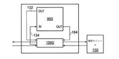
電気的測定システムで使用するためのマネージャシステムであって、第1の態様のプロファイラ機器と、プロファイル概要に少なくとも部分的に基づいて、ネットワークへの通信の報告を生成するように構成された報告生成装置と、を含む。 A manager system for use in electrical measurement systems that is configured to generate reports of communications to the network based on the profiler equipment of the first aspect and at least partly based on the profile summary. Including the device.
報告生成装置は、ネットワークエンティティからオンデマンド報告要求を受信し、プロファイル概要に少なくとも部分的に基づいて報告を生成し、ネットワークエンティティに、通信のオンデマンド報告を出力するようにさらに構成されてもよい。 The report generator may be further configured to receive on-demand reporting requests from network entities, generate reports based at least in part on profile summaries, and output on-demand reports of communications to network entities. ..
プロファイラ機器は、複数のプロファイル結果に少なくとも部分的に基づいて、プロファイル時間の間に起きたセンサイベントを識別するように、さらに構成されてもよく、センサイベントがプロファイラ機器によって識別されるときに、プロファイル概要に少なくとも部分的に基づいて報告を生成するように、報告生成装置はさらに構成されてもよい。 The profiler device may be further configured to identify sensor events that occurred during the profile time, at least in part, based on multiple profile results, when the sensor events are identified by the profiler device. The report generator may be further configured to generate reports based at least in part on the profile summary.
報告は、プロファイル概要を少なくとも部分的に含んでもよい。 The report may include at least a partial profile summary.
報告生成装置は、測定センサによって判定された電気的特性の少なくとも1つの測定および/または、電気的測定システムに関するさらなる特性の少なくとも1つの測定に少なくとも部分的に基づいて、報告を生成するように、さらに構成されてもよい。 The report generator is designed to generate reports based at least in part on at least one measurement of the electrical characteristics determined by the measurement sensor and / or at least one measurement of additional characteristics for the electrical measurement system. It may be further configured.
マネージャシステムは、測定センサによって判定された電気的特性の少なくとも1つの測定および/または、電気的測定システムに関するさらなる特性の少なくとも1つの測定に少なくとも部分的に基づいて、二次プロファイル概要を生成するように構成された二次プロファイラを、さらに含んでもよく、測定センサによって判定された電気的特性の少なくとも1つの測定に少なくとも部分的に基づいて、報告を生成するように、報告生成装置はさらに構成されている。電気的測定システムに関するさらなる特性は、電気的測定システムの温度を含んでもよい。 The manager system will generate a secondary profile summary based at least in part on at least one measurement of the electrical characteristics determined by the measurement sensor and / or at least one measurement of additional characteristics for the electrical measurement system. The report generator is further configured to generate reports based on at least one measurement of the electrical properties determined by the measurement sensor, which may further include a secondary profiler configured in. ing. Further properties with respect to the electrical measurement system may include the temperature of the electrical measurement system.
少なくとも1つの電気的特性を測定するための電気的測定システムであって、第1の電気的特性を測定するための測定センサと、第1の測定センサの伝達関数の推定値および、伝達関数の推定値の精度を示す、対応する確信値を判定するように構成された監視モジュールと、測定センサの伝達関数の推定値および、伝達関数の推定値の精度を示す、対応する確信値を各々が含む、複数のプロファイル結果を取得することであって、プロファイル時間の間に電気的測定システムの監視モジュールによって判定された、測定センサの伝達関数の推定値および対応する確信値に、複数のプロファイル結果が基づく、取得することと、複数のプロファイル結果のうちの少なくとも1つに基づいてプロファイル概要を生成することと、を行うように構成されたプロファイルアナライザと、を含む。電気的測定システムは、ユーティリティメーターであってもよい。 An electrical measurement system for measuring at least one electrical characteristic, wherein the measurement sensor for measuring the first electrical characteristic, the estimated value of the transmission function of the first measurement sensor, and the transmission function A monitoring module configured to determine the corresponding confidence value, which indicates the accuracy of the estimate, and a corresponding confidence value, which indicates the accuracy of the transmission function estimate of the measurement sensor and the transmission function estimate, respectively. To obtain multiple profile results, including, to the estimated and corresponding confidence values of the transmission function of the measurement sensor determined by the monitoring module of the electrical measurement system during the profile time. Includes a profile analyzer configured to perform, acquire, and generate a profile summary based on at least one of a plurality of profile results. The electrical measurement system may be a utility meter.
電気的測定システムの測定センサに関する測定センサプロファイル概要の生成方法であって、測定センサの伝達関数の推定値および、伝達関数の推定値の精度を示す、対応する確信値を各々が含む、複数のプロファイル結果を取得することであって、プロファイル時間の間に電気的測定システムの監視モジュールによって判定された、測定センサの伝達関数の推定値および対応する確信値に、複数のプロファイル結果が基づく、取得することと、複数のプロファイル結果のうちの少なくとも1つに基づいて、プロファイル概要記録を生成することであって、測定センサが電気的特性を測定するためにある、生成することと、を含む。少なくとも1つのプロセッサによって実行されるときに、少なくとも1つのプロセッサに本方法を実行させる、コンピュータ可読命令を格納する、非一時的なコンピュータ可読媒体もまた、開示される。1つ以上のプロセッサに本方法を実行させるように構成されている、ファームウェアモジュールもまた、開示される。 A method of generating a measurement sensor profile summary for a measurement sensor in an electrical measurement system, each containing a corresponding confidence value indicating the accuracy of the transmission function estimate and the transmission function estimate of the measurement sensor. Acquiring profile results, which is based on multiple profile results, based on the estimated and corresponding confidence values of the transmission function of the measurement sensor determined by the monitoring module of the electrical measurement system during the profile time. To generate a profile summary record based on at least one of a plurality of profile results, the measurement sensor is for measuring electrical characteristics. Non-transitory computer-readable media that store computer-readable instructions that cause at least one processor to perform the method when executed by at least one processor are also disclosed. Firmware modules that are configured to cause one or more processors to perform the method are also disclosed.
番号付けされた条項
本開示の非制限態様が、以下の番号付けされた条項において記載される。Numbered Clauses The non-restrictive aspects of this disclosure are set forth in the numbered clauses below.
1.電気的測定システムの監視モジュールの運転を制御するためのコントローラ機器であって、
複数の監視モジュール運転状態のうちの1つを選択し、
選択された監視モジュール運転状態を実現するために、監視モジュールの運転を制御するための制御動作を行うように構成され、
複数の監視モジュール運転状態が、
a)第1の測定センサの伝達関数の推定値および、第1の測定センサの伝達関数の推定値の精度を示す、対応する確信値を含む第1の監視結果を判定するために、少なくともユーティリティメーターの第1の測定センサを監視する、
b)電気的測定システムのいかなる測定センサも監視しない、を含み、
第1の測定センサが第1の電気的特性を測定するためにある、コントローラ機器。1. 1. A controller device for controlling the operation of the monitoring module of an electrical measurement system.
Select one of the multiple monitoring module operating states and
It is configured to perform a control operation to control the operation of the monitoring module in order to achieve the selected monitoring module operating state.
Multiple monitoring module operating status
a) At least a utility to determine the first monitoring result, including the corresponding confidence value, indicating the accuracy of the transfer function estimate of the first measurement sensor and the transfer function estimate of the first measurement sensor. Monitor the first measurement sensor of the meter,
b) Does not monitor any measurement sensor in the electrical measurement system, including
A controller device in which a first measuring sensor is for measuring a first electrical characteristic.
2.監視モジュール運転状態a)が選択される場合に、制御動作が、第1の個別の連続運転時間の間、第1の測定センサを監視して、第1の監視結果を判定するために、第1の制御命令を監視モジュールに通信すること、を含む、条項1に記載のコントローラ機器。 2. When the monitoring module operating state a) is selected, the control operation monitors the first measuring sensor during the first individual continuous operation time to determine the first monitoring result. The controller device according to
3.第1の個別の連続運転時間が固定時間長である、条項2に記載のコントローラ機器。 3. 3. The controller device according to
4.第1の個別の連続運転時間が可変時間長であり、コントローラ機器が、第1の個別の連続運転時間を判定するようにさらに構成されている、条項2に記載のコントローラ機器。 4. The controller device according to
5.第1のセンサの伝達関数の、それぞれの1つ以上の以前判定された推定値に対応する、1つ以上の以前判定された確信値に少なくとも部分的に基づいて、第1の個別の連続運転時間を判定するようにさらに構成されている、条項4に記載のコントローラ機器。 5. First individual continuous operation, at least partially based on one or more previously determined confidence values corresponding to each one or more previously determined estimates of the transfer function of the first sensor. The controller device according to clause 4, further configured to determine time.
6.第1のセンサの伝達関数の、それぞれの1つ以上の以前判定された推定値に対応する、1つ以上の以前判定された確信値を目標確信値と比較することによって、第1の測定センサの伝達関数の推定値のための精度の所望のレベルを達成するために、第1の個別の連続運転時間を判定するようにさらに構成されている、条項5に記載のコントローラ機器。 6. The first measurement sensor by comparing one or more previously determined confidence values corresponding to each one or more previously determined estimates of the transfer function of the first sensor with the target confidence values. The controller device according to clause 5, further configured to determine a first individual continuous operation time in order to achieve a desired level of accuracy for an estimate of the transfer function of.
7.1つ以上の以前判定された確信値が目標確信値達成できない場合に、第1の測定センサの伝達関数の1つ以上の以前判定された推定値の判定において利用された1つ以上の個別の連続運転時間を上回るように、第1の個別の連続運転時間が設定される、条項6に記載のコントローラ機器。 7. One or more used in determining one or more previously determined estimates of the transfer function of the first measurement sensor when one or more previously determined confidence values cannot achieve the target confidence value. The controller device according to clause 6, wherein the first individual continuous operation time is set so as to exceed the individual continuous operation time.
8.1つ以上の以前判定された確信値が目標確信値を超える場合に、第1の測定センサの伝達関数の1つ以上の以前判定された推定値の判定において利用された、1つ以上の個別の連続運転時間を下回るように、第1の個別の連続運転時間が設定される、条項6または7に記載のコントローラ機器。 8. One or more used in determining one or more previously determined estimates of the transfer function of the first measurement sensor when one or more previously determined confidence values exceed the target confidence values. The controller device according to
9.第1の測定センサの伝達関数のそれぞれの1つ以上の以前判定された推定値に対応する、1つ以上の以前判定された確信値に少なくとも部分的に基づいて、複数の監視モジュール運転状態のうちの1つを選択するようにさらに構成されている、条項1〜8のいずれかに記載のコントローラ機器。 9. Multiple monitoring module operating states, at least partially based on one or more previously determined confidence values corresponding to one or more previously determined estimates of the transfer function of the first measurement sensor. The controller device according to any of clauses 1-8, further configured to select one of them.
10.監視時間窓の間に第1の測定センサに関する監視結果を判定する監視モジュールによって費やされる時間の比率が、監視時間窓の間に監視モジュールによって判定される第1の測定センサの伝達関数の推定値が精度の所望のレベルを達成するために十分であるように、複数の監視モジュール運転状態のうちの1つを選択するようにさらに構成されている、条項1〜9のいずれかに記載のコントローラ機器。 10. The ratio of the time spent by the monitoring module to determine the monitoring result for the first measurement sensor during the monitoring time window is the estimated value of the transmission function of the first measurement sensor determined by the monitoring module during the monitoring time window. The controller according to any of clauses 1-9, which is further configured to select one of a plurality of monitoring module operating states such that is sufficient to achieve the desired level of accuracy. device.
11.1つ以上の以前判定された確信値に基づいて、第1の利用目標を判定することであって、第1の測定センサに関する監視結果を判定する監視モジュールによって費やされる監視時間窓の目標合計比率を、第1の利用目標が示す、判定することと、
第1の利用目標に少なくとも部分的に基づいて、複数の監視運転状態のうちの1つを選択することと、を行うように構成されている、条項9または10に記載のコントローラ機器。11. To determine the first utilization goal based on one or more previously determined confidence values, the goal of the monitoring time window spent by the monitoring module to determine the monitoring results for the first measurement sensor. Judging the total ratio as indicated by the first usage target,
The controller device according to clause 9 or 10, wherein the controller device is configured to select and perform one of a plurality of monitored operating conditions, at least in part, based on a first utilization goal.
12.第1の利用目標を判定することが、
1つ以上の以前判定された確信値を、第1の測定センサの伝達関数の推定値のために達成される精度の目標最小レベルと比較することと、
1つ以上の以前判定された確信値が精度の目標最小レベルを達成できない場合に、第1のセンサの伝達関数の1つ以上の以前判定された推定値の判定中に置かれた以前の第1の利用目標を下回るように、第1の利用目標を設定することと、を含む、条項11に記載のコントローラ機器。12. Determining the first usage target
Comparing one or more previously determined confidence values with the target minimum level of accuracy achieved for the transfer function estimate of the first measurement sensor.
The previous number placed during the determination of one or more previously determined estimates of the transfer function of the first sensor when one or more previously determined confidence values fail to reach the target minimum level of accuracy. The controller device according to
13.第1の利用目標を判定することが、
1つ以上の以前判定された確信値を精度の目標最大レベルと比較することと、
1つ以上の以前判定された確信値が精度の目標最大レベルを超える場合に、第1の測定センサの伝達関数の1つ以上の以前判定された推定値の判定中に置かれた以前の第1の利用目標を下回るように、第1の利用目標を設定することと、を含む、条項11または12に記載のコントローラ機器。13. Determining the first usage target
Comparing one or more previously determined confidence values with the target maximum level of accuracy,
The previous number placed during the determination of one or more previously determined estimates of the transfer function of the first measurement sensor when one or more previously determined confidence values exceed the target maximum level of accuracy. The controller device according to
14.複数の監視モジュール運転状態のうちの1つを選択することが、第1の利用目標を電流の第1の利用と比較することを含み、
第1の測定センサに関する監視結果を判定する監視モジュールによってすでに費やされた監視時間窓の比率を、電流の第1の利用が示す、条項11〜13のいずれかに記載のコントローラ機器。14. Choosing one of a plurality of monitoring module operating states involves comparing the first utilization target with the first utilization of current.
The controller device according to any of
15.複数の監視モジュール運転状態が、
c)第2の測定センサの伝達関数の推定値および、第2の測定センサの伝達関数の推定値の精度を示す、対応する確信値を含む第2の監視結果を判定するために、少なくとも電気的測定システムの第2の測定センサを監視することであって、
第2の測定センサが第2の電気的特性を測定するためにある、監視することを行う、をさらに含む、条項1〜14のいずれかに記載のコントローラ機器。15. Multiple monitoring module operating status
c) At least electricity to determine the second monitoring result, including the corresponding confidence value, indicating the accuracy of the transfer function estimate of the second measurement sensor and the transfer function estimate of the second measurement sensor. To monitor the second measurement sensor of the target measurement system,
The controller device according to any of clauses 1-14, further comprising a second measuring sensor for measuring a second electrical characteristic, performing monitoring.
16.監視モジュール運転状態c)が選択される場合に、第2の個別の連続運転時間の間に第2の測定センサを監視して、第2の監視結果を判定するために、第2の制御命令を監視モジュールに通信すること、を制御動作が含む、条項15に記載のコントローラ機器。 16. When the monitoring module operation state c) is selected, a second control command is used to monitor the second measurement sensor during the second individual continuous operation time and determine the second monitoring result. The controller device according to clause 15, wherein the control operation includes communicating with the monitoring module.
17.第2の個別の連続運転時間が固定時間長である、条項16に記載のコントローラ機器。 17. The controller device according to
18.第2の個別の連続運転時間が可変時間長であり、コントローラ機器が、第2の個別の連続運転時間を判定するようにさらに構成されている、条項16に記載のコントローラ機器。 18. The controller device according to
19.第2の測定センサの伝達関数の、それぞれの1つ以上の以前判定された推定値に対応する、1つ以上の以前判定された確信値に少なくとも部分的に基づいて、第2の個別の連続運転時間を判定するようにさらに構成されている、条項18に記載のコントローラ機器。 19. A second individual sequence based, at least in part, on one or more previously determined confidence values corresponding to each one or more previously determined estimates of the transfer function of the second measurement sensor. The controller device according to
20.第2の測定センサの伝達関数の、それぞれの1つ以上の以前判定された推定値に対応する、1つ以上の以前判定された確信値に少なくとも部分的に基づいて、複数の監視モジュール運転状態のうちの1つを選択するようにさらに構成されている、条項15〜19のいずれかに記載のコントローラ機器。 20. Multiple monitoring module operating states based at least in part on one or more previously determined confidence values corresponding to each one or more previously determined estimates of the transfer function of the second measurement sensor. The controller device according to any of clauses 15-19, further configured to select one of them.
21.第1の測定センサに関する推定値のための精度の第1の目標レベルおよび/または、第2の測定センサに関する推定値のための精度の第2の目標レベルに少なくとも部分的に基づいて、複数の監視モジュール運転状態のうちの1つを選択するようにさらに構成されている、条項15〜20のいずれかに記載のコントローラ機器。 21. A plurality, at least in part, based on the first target level of accuracy for the estimates for the first measurement sensor and / or the second target level of accuracy for the estimates for the second measurement sensor. The controller device according to any of clauses 15-20, further configured to select one of the monitoring module operating conditions.
22.精度の第1の目標レベルおよび記精度の第2の目標レベルに基づいて、監視時間窓の間に第1の測定センサに関する監視結果を判定する監視モジュールによって費やされる時間の比率および、監視時間窓の間に第2の測定センサに関する監視結果を判定する監視モジュールによって費やされる時間の比率を最適化するために、複数の監視モジュール運転状態のうちの1つを選択するようにさらに構成されている、条項21に記載のコントローラ機器。 22. The ratio of the time spent by the monitoring module to determine the monitoring result for the first measurement sensor during the monitoring time window and the monitoring time window based on the first target level of accuracy and the second target level of accuracy. It is further configured to select one of a plurality of monitoring module operating states in order to optimize the ratio of time spent by the monitoring module to determine the monitoring result with respect to the second measurement sensor. , The controller device according to clause 21.
23.第1のセンサの伝達関数の、それぞれの1つ以上の以前判定された推定値に対応する、1つ以上の以前判定された確信値に基づいて、第1の利用目標を判定することであって、電気的測定システムの第1の測定センサに関する監視結果を判定する監視モジュールによって費やされる監視時間窓の目標合計比率を、第1の利用目標が示す、判定することと、
第2のセンサの伝達関数の、それぞれの1つ以上の以前判定された推定値に対応する、1つ以上の以前判定された確信値に基づいて、第2の利用目標を判定することであって、電気的測定システムの第2の測定センサに関する監視結果を判定する監視モジュールによって費やされる監視時間窓の目標合計比率を、第2の利用目標が示す、判定することと、
第1の利用目標および第2の利用目標に少なくとも部分的に基づいて、複数の監視運転状態のうちの1つを選択することと、によって、複数の監視運転状態のうちの1つを選択するようにさらに構成されている、条項15〜22のいずれかに記載のコントローラ機器。23. Determining the first utilization target based on one or more previously determined confidence values corresponding to each one or more previously determined estimates of the transfer function of the first sensor. The first utilization target indicates and determines the target total ratio of the monitoring time window spent by the monitoring module that determines the monitoring result for the first measurement sensor of the electrical measurement system.
Determining a second utilization target based on one or more previously determined confidence values corresponding to each one or more previously determined estimates of the transfer function of the second sensor. The second utilization target indicates and determines the target total ratio of the monitoring time window spent by the monitoring module that determines the monitoring result for the second measurement sensor of the electrical measurement system.
Select one of the plurality of monitored operating states by selecting one of the plurality of monitored operating states, at least in part, based on the first and second utilization goals. The controller device according to any of clauses 15-22, further configured as described above.
24.複数の監視モジュール運転状態のうちの1つを選択することが、第1の利用目標を電流の第1の利用と比較することと、第2の利用目標を電流の第2の利用と比較することと、を含み、
第1の測定センサに関する監視結果を判定する監視モジュールによってすでに費やされた監視時間窓の比率を、電流の第1の利用が示し、
第2の測定センサに関する監視結果を判定する監視モジュールによってすでに費やされた監視時間窓の比率を、電流の第2の利用が示す、条項23に記載のコントローラ機器。24. Choosing one of a plurality of monitoring module operating states compares the first utilization target with the first utilization of current and the second utilization target with the second utilization of current. Including that
The first utilization of current shows the ratio of the monitoring time window already spent by the monitoring module that determines the monitoring result for the first measurement sensor.
The controller device according to
25.少なくとも1つの電気的特性を測定するための電気的測定システムであって、
第1の電気的特性を測定するための第1の測定センサと、
を含む複数の監視モジュール運転状態のうちの1つにおいて動作するように構成されている監視モジュールであって、
a)第1の測定センサの伝達関数の推定値および、第1の測定センサの伝達関数の推定値の精度を示す、対応する確信値を含む第1の監視結果を判定するために、少なくとも第1の測定センサを監視する、
b)電気的測定システムのいかなる測定センサも監視しない、を含む、監視モジュールと、
複数の監視モジュール運転状態のうちの1つを選択し、
選択された監視モジュール運転状態を実現するために、監視モジュールの運転を制御するための制御動作を行うように構成されたコントローラと、を含む、電気的測定システム。25. An electrical measurement system for measuring at least one electrical property.
A first measurement sensor for measuring the first electrical characteristics,
A monitoring module configured to operate in one of a plurality of operating states, including
a) At least a first monitoring result, including a corresponding confidence value, indicating the accuracy of the transfer function estimate of the first measurement sensor and the transfer function estimate of the first measurement sensor.
b) A monitoring module, including, which does not monitor any measurement sensor in the electrical measurement system.
Select one of the multiple monitoring module operating states and
An electrical measurement system, including a controller configured to perform a control operation to control the operation of the monitoring module to achieve the selected monitoring module operating state.
26.電気的測定システムの監視モジュールの制御方法であって、
複数の監視モジュール運転状態のうちの1つを選択することと、
選択された監視モジュール運転状態を実現するために、監視モジュールの運転を制御するための制御動作を行うことと、を含み、
複数の監視モジュール運転状態が、
a)第1の測定センサの伝達関数の推定値および、第1の測定センサの伝達関数の推定値の精度を示す、対応する確信値を含む第1の監視結果を判定するために、少なくとも電気的測定システムの第1の測定センサを監視する、と、
b)電気的測定システムのいかなる測定センサも監視しない、を含み、
第1の測定センサが第1の電気的特性を測定するためにある、方法。26. It is a control method of the monitoring module of the electrical measurement system.
Selecting one of multiple monitoring module operating states and
Including performing a control operation to control the operation of the monitoring module in order to realize the selected monitoring module operating state.
Multiple monitoring module operating status
a) At least electricity to determine the first monitoring result, including the corresponding confidence value, indicating the accuracy of the transmission function estimate of the first measurement sensor and the transmission function estimate of the first measurement sensor. Monitor the first measurement sensor of the target measurement system,
b) Does not monitor any measurement sensor in the electrical measurement system, including
A method in which a first measuring sensor is for measuring a first electrical characteristic.
27.少なくとも1つのプロセッサによって実行されるときに、少なくとも1つのプロセッサに条項26に記載の方法を実行させる、コンピュータ可読命令を格納する、非一時的なコンピュータ可読媒体。 27. A non-transitory computer-readable medium that stores computer-readable instructions that, when executed by at least one processor, causes at least one processor to perform the method described in
28.電気的測定システムで使用するためのプロファイラ機器であって、
電気的測定システムの測定センサの伝達関数の推定値および、伝達関数の推定値の精度を示す、対応する確信値を各々が含む複数のプロファイル結果を取得することであって、複数のプロファイル結果がプロファイル時間の間に電気的測定システムの監視モジュールによって判定された、測定センサの伝達関数の推定値および対応する確信値に基づく、取得することと、
複数のプロファイル結果のうちの少なくとも1つに基づいてプロファイル概要を生成することであって、
測定センサが電気的特性を測定するためにある、ように構成された、プロファイルアナライザを含む、プロファイラ機器。28. Profiler equipment for use in electrical measurement systems
Acquiring multiple profile results, each containing a corresponding confidence value, indicating the accuracy of the transfer function estimate and the transfer function estimate of the measurement sensor of the electrical measurement system. To obtain and to obtain, based on the transfer function estimates and corresponding confidence values of the measurement sensor, as determined by the monitoring module of the electrical measurement system during the profile time.
Generating a profile summary based on at least one of a plurality of profile results,
A profiler device, including a profile analyzer, configured such that a measurement sensor is for measuring electrical characteristics.
29.プロファイル概要が、
複数のプロファイル結果における伝達関数の推定値の有効平均と、
複数のプロファイル結果における確信値の有効平均と、
複数のプロファイル結果における伝達関数の推定値の有効平均とベンチマーク伝達関数値との間の差異と、
複数のプロファイル結果におけるプロファイル結果の数と、
伝達関数の推定値および対応する確信値を判定する監視モジュールによって費やされたプロファイル時間の比率と、のうちの少なくとも1つを示す、条項28に記載のプロファイラ機器。29. Profile overview
Effective average of transfer function estimates in multiple profile results,
Effective average of confidence values in multiple profile results and
Differences between the effective mean of transfer function estimates and benchmark transfer function values in multiple profile results,
The number of profile results in multiple profile results and
The profiler device according to
30.プロファイラ機器が、
複数の伝達関数の推定値および対応する複数の確信値に少なくとも部分的に基づいて、伝達関数の推定値の有効平均、を判定するようにさらに構成されている、条項28または29に記載のプロファイラ機器。30. Profiler equipment,
The profiler according to
31.伝達関数の推定値の有効平均の判定が、
複数の伝達関数の推定値の各々に、それらの対応する確信値に基づいて重み付けを行うことと、
重み付けされた複数の伝達関数の推定値に少なくとも部分的に基づいて、伝達関数の推定値の有効平均を判定すること、を含む、条項30に記載のプロファイラ機器。31. Judgment of the effective average of the estimated value of the transfer function,
Weighting each of the estimates of multiple transfer functions based on their corresponding beliefs,
The profiler device according to
32.複数のプロファイル結果に少なくとも部分的に基づいて、プロファイル時間の間に起きたセンサイベントを識別する、ようにさらに構成されている、条項28〜31のいずれかに記載のプロファイラ機器。 32. The profiler device according to any of clauses 28-31, further configured to identify sensor events that have occurred during the profile time, at least in part, based on a plurality of profile results.
33.センサイベントを識別することが、複数のプロファイル結果の少なくともいくつかにおける、伝達関数の推定値に少なくとも部分的に基づく、条項32に記載のプロファイラ機器。 33. The profiler device according to Clause 32, wherein identifying a sensor event is at least partially based on an estimate of the transfer function in at least some of the profile results.
34.センサイベントを識別することが、複数のプロファイル結果の少なくともいくつかにおける伝達関数の推定値をベンチマーク伝達関数値と比較することと、を含み、イベント閾値量より大きくベンチマーク伝達関数値とは異なる伝達関数の推定値を含むプロファイル結果が、プロファイル時間の間に起きたセンサイベントを示す、条項33に記載のプロファイラ機器。 34. Identifying sensor events involves comparing transfer function estimates in at least some of the multiple profile results with the benchmark transfer function values, including transfer functions that are greater than the event threshold and differ from the benchmark transfer function values. 33. The profiler device according to clause 33, wherein the profile result, including an estimate of, indicates a sensor event that occurred during the profile time.
35.プロファイル結果がセンサイベントを示すと判定される場合に、プロファイル概要が、ベンチマーク伝達関数とそのプロファイル結果における伝達関数の推定値との間の差異の大きさの指示を含む、条項34に記載のプロファイラ機器。 35. The profiler according to Clause 34, wherein if the profile result is determined to indicate a sensor event, the profile summary contains an indication of the magnitude of the difference between the benchmark transfer function and the transfer function estimate in the profile result. device.
36.最大差異閾値より大きくベンチマーク伝達関数値とは異なる伝達関数の推定値を含むプロファイル結果が、信号不良センサイベントを示す、条項34または35に記載のプロファイラ機器。 36. The profiler device according to
37.センサイベントを識別することが、複数のプロファイル結果の少なくともいくつかにおける確信値に少なくとも部分的に基づく、条項33〜36のいずれかに記載のプロファイラ機器。 37. The profiler device according to any of clauses 33-36, wherein identifying a sensor event is at least partially based on confidence values in at least some of the profile results.
38.センサイベントを識別することが、複数のプロファイル結果のうちの1つ以上における確信値を、精度の閾値最小レベルと比較することを含む、条項37に記載のプロファイラ機器。 38. The profiler device according to Clause 37, wherein identifying a sensor event comprises comparing a confidence value in one or more of a plurality of profile results with a threshold minimum level of accuracy.
39.精度の閾値最小レベルがイベント閾値量に基づく、条項38に記載のプロファイラ機器。 39. The profiler device according to Clause 38, wherein the threshold minimum level of accuracy is based on the amount of event threshold.
40.イベント閾値量および、精度の最小レベルを達成する伝達関数の推定値の精度を示す、対応する確信値より大きくベンチマーク伝達関数値とは異なる伝達関数の推定値を含むプロファイル結果が、プロファイル時間の間に起きたセンサイベントを示す、条項38または39に記載のプロファイラ機器。 40. A profile result that contains a transfer function estimate that is greater than the corresponding confidence value and is different from the benchmark transfer function value, which indicates the accuracy of the transfer function estimate that achieves the event threshold amount and the minimum level of accuracy, is during the profile time. The profiler device according to clause 38 or 39, which indicates a sensor event that has occurred in.
41.複数のプロファイル結果における確信値の有効平均が、
精度の閾値最小レベルを満たさない精度を示す場合に、精度不良センサイベントが識別される、条項38〜40のいずれかに記載のプロファイラ機器。41. The effective average of confidence values in multiple profile results is
The profiler device according to any of clauses 38-40, wherein a poor accuracy sensor event is identified if it exhibits accuracy that does not meet the accuracy threshold minimum level.
42.センサイベントが、プロファイル時間の間の伝達関数の一時的変化を示すバーストイベントを含む、条項32〜41のいずれかに記載のプロファイラ機器。 42. The profiler device according to any of clauses 32-41, wherein the sensor event comprises a burst event indicating a transient change in the transfer function during the profile time.
43.センサイベントが、プロファイル時間の間の伝達関数の持続的変化を示す変更イベントを含む、条項32〜41のいずれかに記載のプロファイラ機器。 43. The profiler device according to any of clauses 32-41, wherein the sensor event comprises a change event indicating a persistent change in the transfer function during the profile time.
44.電気的測定システムの監視モジュールから複数の監視結果を取得することであって、複数の監視結果の各々が、
プロファイル時間内にある個別の連続運転時間に亘って監視モジュールによって判定された、測定センサの伝達関数の推定値と、
伝達関数の推定値の精度を示す、対応する確信値を含む、取得することと、
複数の監視結果に少なくとも部分的に基づいて、複数のプロファイル結果を判定することと、を行うように構成された、データストアマネージャをさらに含む、条項28〜43のいずれかに記載のプロファイラ機器。44. Obtaining multiple monitoring results from the monitoring module of the electrical measurement system, each of the multiple monitoring results
Estimates of the transfer function of the measurement sensor as determined by the monitoring module over the individual continuous operating times within the profile time.
To obtain, including the corresponding certainty value, which indicates the accuracy of the transfer function estimate,
The profiler device according to any of clauses 28-43, further comprising a data store manager, configured to determine and perform multiple profile results based on, at least in part, multiple monitoring results.
45.データストアマネージャが、
連続する期間に亘って判定された2つ以上の監視結果を識別することと、
識別された2つ以上の監視結果における伝達関数の推定値に少なくとも部分的に基づいて、プロファイル結果のための伝達関数の推定値を判定することと、
識別された2つ以上の監視結果における確信値に少なくとも部分的に基づいて、プロファイル結果のための確信値を判定することと、によって、複数のプロファイル結果のプロファイル結果のうちの少なくとも1つを判定するように構成された、条項44に記載のプロファイラ機器。45. Data store manager
Identifying two or more monitoring results determined over consecutive periods
Determining the transfer function estimate for the profile result, at least in part, based on the transfer function estimate in the two or more identified monitoring results.
Determine at least one of the profile results of a plurality of profile results by determining the confidence value for the profile result, at least in part, based on the confidence values in the two or more identified monitoring results. The profiler device according to clause 44, configured to.
46.電気的測定システムで使用するためのマネージャシステムであって、
条項28〜45のいずれかに記載のプロファイラ機器と、
プロファイル概要に少なくとも部分的に基づいて、ネットワークへの通信の報告を生成するように構成された報告生成装置と、を含む、マネージャシステム。46. A manager system for use in electrical measurement systems
With the profiler device described in any of clauses 28-45,
A manager system, including a report generator, which is configured to generate reports of communications to the network, at least in part based on a profile overview.
47.測定センサによって判定された電気的特性の少なくとも1つの測定および/または、電気的測定システムに関するさらなる特性の少なくとも1つの測定に少なくとも部分的に基づいて、報告を生成するように、報告生成装置がさらに構成されている、条項46に記載のマネージャシステム。 47. The report generator further so as to generate a report based at least in part on at least one measurement of the electrical characteristics determined by the measurement sensor and / or at least one measurement of additional characteristics for the electrical measurement system. The manager system according to clause 46, which is configured.
48.測定センサによって判定された電気的特性の少なくとも1つの測定および/または、電気的測定システムに関するさらなる特性の少なくとも1つの測定に少なくとも部分的に基づいて、二次プロファイル概要を生成するように構成された二次プロファイラをさらに含み、
測定センサによって判定された電気的特性の少なくとも1つの測定に少なくとも部分的に基づいて、報告を生成するように、報告生成装置がさらに構成されている、条項46に記載のマネージャシステム。48. It was configured to generate a secondary profile summary based at least in part on at least one measurement of the electrical characteristics determined by the measurement sensor and / or at least one measurement of additional characteristics for the electrical measurement system. Including a secondary profiler,
46. The manager system of clause 46, wherein the report generator is further configured to generate reports based at least in part on at least one measurement of the electrical characteristics determined by the measurement sensor.
49.少なくとも1つの電気的特性を測定するための電気的測定システムであって、
第1の電気的特性を測定するための測定センサと、
第1の測定センサの伝達関数の推定値および、伝達関数の推定値の精度を示す、対応する確信値を判定するように構成された監視モジュールと、
測定センサの伝達関数の推定値および、伝達関数の推定値の精度を示す、対応する確信値を各々が含む、複数のプロファイル結果を取得することであって、プロファイル時間の間に電気的測定システムの監視モジュールによって判定された、測定センサの伝達関数の推定値および対応する確信値に、複数のプロファイル結果が基づき、取得することと、
複数のプロファイル結果のうちの少なくとも1つに基づいてプロファイル概要を生成することと、を行うように構成された、プロファイルアナライザと、を含む、電気的測定システム。49. An electrical measurement system for measuring at least one electrical property.
A measurement sensor for measuring the first electrical characteristics,
A monitoring module configured to determine the transfer function estimate of the first measurement sensor and the corresponding confidence value that indicates the accuracy of the transfer function estimate.
Obtaining multiple profile results, each containing a corresponding confidence value, indicating the accuracy of the transfer function estimate of the measurement sensor and the transfer function estimate, an electrical measurement system during the profile time. Based on the results of multiple profiles, the estimated value of the transfer function of the measurement sensor and the corresponding certainty value determined by the monitoring module of
An electrical measurement system, including a profile analyzer, configured to generate and perform profile summaries based on at least one of a plurality of profile results.
50.電気的測定システムの測定センサに関する測定センサプロファイル概要の生成方法であって、
測定センサの伝達関数の推定値および、伝達関数の推定値の精度を示す、対応する確信値を各々が含む、複数のプロファイル結果を取得することであって、プロファイル時間の間に電気的測定システムの監視モジュールによって判定された、測定センサの伝達関数の推定値および対応する確信値に、複数のプロファイル結果が基づく、取得することと、
複数のプロファイル結果のうちの少なくとも1つに基づいて、プロファイル概要記録を生成することであって、
測定センサが電気的特性を測定するためにある、生成することと、を含む、方法。50. A method of generating a measurement sensor profile summary for a measurement sensor in an electrical measurement system.
Obtaining multiple profile results, each containing a corresponding confidence value, indicating the accuracy of the transfer function estimate of the measurement sensor and the transfer function estimate, an electrical measurement system during the profile time. Based on multiple profile results based on the transfer function estimates and corresponding confidence values of the measurement sensor determined by the monitoring module of
Generating a profile summary record based on at least one of a plurality of profile results.
A method, including generating, in which a measuring sensor is for measuring electrical characteristics.
51.少なくとも1つのプロセッサによって実行されるときに、少なくとも1つのプロセッサに条項60に記載の方法を実行させる、コンピュータ可読命令を格納する、非一時的なコンピュータ可読媒体。 51. A non-transitory computer-readable medium that stores computer-readable instructions that, when executed by at least one processor, causes at least one processor to perform the method described in
本開示について、単なる例示として、以下の図面を参照して説明する。
ユーティリティメーターなどの電気的測定システムは、測定フロントエンドおよびマイクロコントローラユニット(MCU)を含んでもよい。測定フロントエンドは、電気的パラメータ(例えば、電圧および/または電流)測定し、また、潜在的には、電気的パラメータの測定値に基づいて消費された電気の量を計算してもよい。MCUは、測定フロントエンドの設定、測定フロントエンドからの結果の読み取り、任意のローカルディスプレイの電気的測定システム上での駆動、より良好なバックアップシステムの有効化、リアルタイムクロック(RTC)の運転などの多くの機能を実行してもよい。 An electrical measurement system such as a utility meter may include a measurement front end and a microcontroller unit (MCU). The measurement front end may measure electrical parameters (eg, voltage and / or current) and potentially calculate the amount of electricity consumed based on the measured values of the electrical parameters. The MCU can configure the measurement front end, read the results from the measurement front end, drive any local display on the electrical measurement system, enable a better backup system, run the real-time clock (RTC), etc. Many functions may be performed.
本開示の態様について、ユーティリティメーターシステムの文脈において、以下に開示する。しかしながら、本開示はその文脈のみに限定されず、任意の種類の電気的測定システムに応用されてもよいことが理解される。 The aspects of this disclosure are disclosed below in the context of a utility meter system. However, it is understood that the present disclosure is not limited to that context and may be applied to any type of electrical measurement system.
図1は、本開示の第1の態様による、ユーティリティメーターシステム100を模式的に示す。ユーティリティメーターシステム100は、監視モジュール110、測定センサ120、MCU130、メモリ140および通信モジュール150を含む。ユーティリティメーターシステム100は、通信モジュール150を利用して、ネットワークエンティティ160(例えば、ユーティリティクラウド)とインターフェースするように構成されている。 FIG. 1 schematically shows a
通信モジュール150は、Ethernet、Bluetooth(登録商標)、WiFi、WiMAX、GSM(登録商標)、GPRS、EDGE、UMTS、LTEなどの任意の1つ以上の有線または無線通信プロトコル、規格またはアーキテクチャに従って、それらのプロトコル、規格またはアーキテクチャのうちの任意の1つ以上に従う通信モジュール150を介して、ネットワークエンティティ160とユーティリティメーターシステム100との間の通信が発生してもよいように、構成されてもよい。 The
メモリ140は、揮発性および/または不揮発性メモリ、例えばRAM、ROM、フラッシュメモリ、ソリッドステートメモリ、磁気テープ、ハードディスクドライブなどの任意の好適な形式のメモリを含んでもよい。 The
後に明らかになるように、測定センサ120は、上述の測定フロントエンドの一部を形成してもよい。 As will become apparent later, the
監視モジュール110は、測定センサ120のうちの1つ以上に関する伝達関数の推定値(センササイズまたはゲインの推定値とも称され、以下「CC」と称される)および各々の推定値のための対応する確信値(以下と称される「Cert」)を判定するように構成されている。CCおよびCert値のさらなる詳細について、本開示において後に明らかにする。監視モジュール110がCCおよびCertをいかに判定し得るかについての実装詳細は本開示の主題ではないが、それでもなお、まず、ユーティリティ消費メータ100がいかに電力消費を測定するように構成されてもよいか(例えば、測定フロントエンド)、また、監視モジュール110がいかにCCおよびCertを判定し得るかの例示的な構成を説明することは有用であり得る。 The
図2は、ユーティリティメーターシステム100(例えば、ユーティリティメーターシステム100のフロントエンド)の一部を形成してもよい、電力測定機器の例を模式的に示す。この例では、通電導体14および中性導体16を有する単相電源交流電気供給12が負荷18を供給する。負荷18によって消費される電力の量は、通電および中性導体14および16の間の電圧、負荷18によって引き込まれる電流、および、正弦波電圧電流に関する交流電圧波形と交流電流波形との間の位相角に依存する。例えば、引き込まれた電流の量において大幅な調和成分が存在する、より複雑な波形に関しては、消費された瞬時電力の合計の実行を保つことによって、電力消費が測定されるべきである。 FIG. 2 schematically illustrates an example of a power measuring device that may form part of a utility meter system 100 (eg, the front end of the utility meter system 100). In this example, the single-phase power supply AC
電流を測定するために、電力測定機器は、この例では、負荷18と電気供給12との間の通電導体14によって表される導電性パスにおける公称で指定された抵抗のシャント抵抗20である測定センサを、有する。典型的には、シャント抵抗は、ミリオームなどの単位で、非常に低い値である。シャント抵抗20の両端に降下される電圧は、それを通過する電流に比例する。結果として、シャント抵抗は、電圧伝達関数に対して、電流を有するようにみなされ得る。結果として、シャント抵抗20の両端の電圧を測定し、抵抗20の抵抗が熟知されている場合に、または、より正確には、項目20および22の伝達関数が熟知されている場合に、信号処理回路24にその出力を提供するように配置された電圧測定機器22によって、導体14における電流の推定値が確実に作製され得る。測定機器22は、適度なダイナミックレンジを有するアナログデジタル変換器が、少なくともより小さい電流において、分解能を失うことなく、非常に小さいから非常に大きいまでの電流の範囲を扱うことを可能にするように、電流信号に応用されるゲインを変更するためのプログラム可能なゲイン増幅器を含んでもよい。したがって、図1の測定センサ120は通電導体電流測定項目(すなわち、シャント抵抗20および測定機器22)を含んでもよいことが理解される。通電導体14における電流、または相電流は、以下IAと称される。To measure the current, the power measuring instrument is, in this example, a measurement of the
図2には表されないが、電力測定機器は追加的に、または代替的に、通電導体14に関して上述したのと同様の方法で、中性導体16における電流を測定するように構成されてもよい。それは、中性導体の電流パスにおけるシャント抵抗を測定センサとして同様に利用してもよいか、または、変流器(CT)などの任意の他の好適な測定センサを代替的に利用してもよい。したがって、図1の測定センサ120は、追加的に、または代替的に、中性導体電流測定項目(すなわち、シャント抵抗またはCT、および測定機器)を含むことが理解される。中性導体16における電流、または中性電流は、以下IBと称される。Although not shown in FIG. 2, the power measuring device may be additionally or optionally configured to measure the current in the
追加的に、通電導体14と中性導体16との間の電圧差を測定するために、電圧測定機器26が提供される。電圧が通常、115〜250ボルトRMSの範囲にある世帯環境においては、それゆえに300ボルトを超えるピーク電圧を経験してもよい。結果として、電源電圧領域からの入力電圧を、例えば、電圧測定機器26内のアナログデジタル変換器による信号取得により好適な、より小さい電圧領域に変圧するために、電圧測定機器26はしばしば、図3においてより詳細に説明するように、分圧器を含む。したがって、図1の測定センサ120は電圧測定機器26を含んでもよいことが理解される。 Additionally, a
異なる供給電圧を有する設置または国において、測定回路の単一の設定が利用され得るように、電圧測定機器26は、プログラム可能な電圧減衰器および/またはプログラム可能な増幅器を含んでもよい。供給12からの負荷18によって取られた二乗平均平方根電力を計算し、任意には、負荷18を動作させる消費者が、電源12から受けた電力の量に関して適切な請求を受けるために、それに料金を乗算するように適合された算出ユニット28に、電圧測定機器26および電流測定機器20、22、24からの電圧および電流の瞬時測定値が提供されてもよい。電力消費の正しく適切な算出のために各々の電圧および電流測定が時間領域に適切に割り当てられるように、算出ユニット28はリアルタイムクロック30に関連してもよい。 The
図3は、導体14から入力電圧Vinを受け、導体16において提供される中性電圧に関連して、それを分割する分圧器35への抵抗を模式的に示す。この例では、第1および第2の抵抗40および42は、導体14および16の間で直列に接続される。各々の抵抗を通過する同じ電流および、したがって出力電圧Voは、以下によって、入力電圧に関連し得る。 FIG. 3 schematically shows the resistance to the
Vo=(Vin.R2)/(R1+R2) Vo = (Vin.R2) / (R1 + R2)
R1は抵抗40の値であり、R2は抵抗42の値である。したがって、分圧器は、抵抗R1およびR2の相対値によって設定された伝達関数を有する。電圧を正確に知るためには、分圧器の伝達関数を正確に知るべきである。測定された電圧、または相電圧は、以下VAと称される。R1 is the value of the
IAおよび/またはIBおよびVAを測定するように構成された電力測定機器を含むユーティリティメーターシステム100について上で説明したが、代替的に、IA、IBおよび/またはVAのうちのいずれか1つ以上を測定するように構成されてもよいことが理解される。さらに、IA、IBおよび/またはVAを測定するための電力測定機器の特定の構成について上で説明したが、本開示はそのように限定されず、ユーティリティ消費メータ100は、任意の好適な方法でIAおよび/またはIBおよび/またはVAを測定するように構成されてもよい。It has been described above for the
測定センサ120はしたがって、IA、IBおよび/またはVAのうちのいずれか1つ以上を測定するための1つ以上の項目を含んでもよい。例えば、測定センサ120は、1つ以上のシャント抵抗ならびに、IAおよび/またはIBを測定するための測定機器22、1つ以上の変流器(CT)ならびにIAおよび/またはIBを測定するための測定機器22、および/または、VAを測定するための1つ以上の電圧測定機器26を含んでもよい。Measuring
監視モジュール110は、測定センサ120の伝達関数の推定値(CC)を判定するように構成されている。それは、IAを測定するための測定センサ(例えば、シャント抵抗/CTおよび測定機器22)および/または、IBを測定するための測定センサ(例えば、シャント抵抗/CTおよび測定機器22)および/または、VAを測定するための測定センサ(例えば、電圧測定機器26)のCCを判定するように構成されてもよい。電圧および電流伝達関数を推定する方法に関して実行可能な開示のために読者が参照し、本明細書にそれらの全体が参照により援用されている、WO2014/072733およびWO2013/038176において、伝達関数の推定値を判定する方法が開示されている。しかしながら、参照を容易にするために、それらの特許出願の例が、本明細書に含まれる。The
WO2014/072733において、電圧測定回路に関する伝達関数の推定値は、いくつかの手法によって判定され得る。図4に示されるような一手法は、いずれかが図3における第1の抵抗40を表す外部抵抗Rextを有する分圧器を形成してもよいように、正確に知られた値(Rint1およびRint2)を有するために、2つの抵抗50および52を提供することである。直列接続したスイッチ60および62の制御のもとで、抵抗40と抵抗50との、その後、抵抗40と抵抗52との間に連続する分圧器を形成することにより、異なる分割率が形成され、抵抗50および52の値が熟知されている場合に、その後、分圧器の伝達関数の推定値が判定され得る。スイッチ60および62はキャリブレーション逆位相において駆動され、一方で、分圧器の分割率を公称で一貫するように維持するために、通常の利用においては、一方のスイッチ、例えばSW1、はオンのままであり、かたや、他方はオフである。In WO2014 / 072733, the estimated value of the transfer function for the voltage measuring circuit can be determined by several methods. One approach, as shown in Figure 4, either as may form a voltage divider with an external resistor Rext which represents the
例えば、スイッチ60および62のうちの1つの不良による抵抗50および52の両端において発生し得る最大電圧(順および逆の両方)を制限するために、ツェナーダイオード65などの保護装置が提供されてもよいが、これらは、電界効果トランジスタとして実装される可能性が高い。ADC68によって、出力電圧V0が測定される。For example, a protective device such as a
図5に示されるような別の手法は、分圧器の両端の電圧を連続的に変更することである。R2とローカル地面との間で作用する電圧を変更することによって最も簡便に実行される。図5において、分圧器を作成するために、抵抗40および42が再び直列に提供される、このような配置が示される。しかしながら、抵抗40につながれていない抵抗42の端部は、第1のスイッチ70によって直接連続的に地面に、または、第2のスイッチ72に直列な電源74によって地面に接続されるかのいずれかであり得る。したがって、図6に示されるように、S1およびS2を連続的に切り替えることで、分圧器の出力における電圧が変調される。電圧74の値が確実度の事前判定されたレベル(設計者が指定する通り)内にあると知られている場合に、その後、第2の抵抗42の値が知られると、分圧器の伝達関数の推定値電圧が判定され得る。さらに、電圧74が2つ以上の制御可能な出力電圧を提供し得る場合に、抵抗40および42によって形成される分圧器の伝達関数の推定値は、抵抗40または42のいずれかの値を知ることなく、判定され得る。出力電圧Voはその後、デジタルフィルタ24などの続く回路への供給前に、デジタル領域への変換のために、アナログデジタル変換器68に供給される。電源およびスイッチは、例えば、抵抗42の接地電圧を毛生する演算増幅器に関連してもよい。 Another approach, as shown in FIG. 5, is to continuously change the voltage across the voltage divider. It is most conveniently performed by changing the voltage acting between R2 and the local ground. FIG. 5 shows such an arrangement in which resistors 40 and 42 are provided again in series to create a voltage divider. However, the end of the
本明細書に説明する技術、またはWO2014/072733における他の技術は、本開示の実施において交換可能に利用され得、単相または多相システムのいずれかに適切である。 The techniques described herein, or other techniques in WO2014 / 072733, may be interchangeably utilized in the practice of the present disclosure and are suitable for either single-phase or polyphase systems.
同様に、上述のように、監視モジュール110はまた、IAおよび/またはIBを測定するための測定センサ(複数可)のCCを判定するように構成されてもよい。Similarly, as discussed above,
好適な例示的な配置が図7に示される。ここではシャント抵抗20が、図2を参照して示されたように、電源12と負荷18との間の通電導体の電流パスにおいて、接続されている。シャント抵抗20の両端の電圧は、電圧測定回路22によって、例えば、アナログデジタル変換器の形式で測定される。電流測定パスの伝達関数の推定値を判定するために、抵抗20を通って追加的な電流を制御可能に通過させ得る制御可能な電源/電流シンクを含む電流測定回路80が提供される。抵抗20の抵抗は非常に低く、したがって、接触時の不純物の結果としての変化の影響を受けやすく、したがって、値が極めて不確実になり得る。値が熟知され、制御されているその追加的な電流は、抵抗20の両端の対応する電圧変化を引き起こし、それはアナログデジタル変換器22によって測定され得、またその後、電流測定パスの伝達関数の推定値を判定するために、この情報が利用され得る。図7に示す配置において、回路80は抵抗の一端に電流を注入し、他方よりそれを取り除く。したがって、この配置において、電流は双方向であってもよい。しかしながら、他の配置においては、電流が抵抗を通過して引き込まれるように、抵抗20の負荷端のみが接続される可能性がある。 A suitable exemplary arrangement is shown in FIG. Here, the
制御可能な電源80は例えば、オンまたはオフのいずれかになるように、実質的に双方向な方法で、動作してもよい。しかしながら、WO2013/038176におけるように、電源はまた、分解能を上回る複数の電流値に変調されてもよい。例えばその図17cを参照のこと。 The
したがって、監視モジュール110は、IA、IBおよび/またはVA測定センサのうちのいずれか1つ以上の伝達関数を推定してもよい。伝達関数の推定のための特定の技術について上記で開示したが、監視モジュール110は、任意の好適な方法で、伝達関数を判定するように構成されてもよいことが理解される。Therefore, the monitoring module110, I A, may be estimated either one or more transfer functions of theI B and / orV A measuring sensor. Although the specific techniques for estimating the transfer function have been disclosed above, it is understood that the
監視モジュール110はまた、各々のCCのための確信値(Cert)を判定するように構成されてもよい。Certは、CCが正しいことの確実度(または信頼度)を示す(または確実度/信頼度の換質命題である不確実度を示す)。Certは、例えばパーセンテージ値、またはデシマル値などの、任意の好適な形式を取ってもよい。ある特定の例において、Certは、パーセンテージ値の形式を取ってもよく、パーセンテージ値が低いほど、より高い確実度を示す。例えば、1%のCertは、判定されたCCが+/−1%以内の誤差であることを示し、50%のCertは、判定されたCCが+/−50%以内の誤差であることを示すなどである。このようにして、Certは、その対応するCCに関する誤差バーを定義するものとして考えられてもよい。 The
CCに関するCertを判定する方法は、PCT/US2016/068089に記載があり、CCに関するCertを判定する方法に関する実行可能な開示のために、読者がそれを参照し、また、本明細書にその全体が参照により援用されている。しかしながら、参照を容易にするために、その特許出願の例は、本明細書に含まれる。 A method for determining Cert for CC is described in PCT / US2016 / 068089, which the reader may refer to for viable disclosure of a method for determining Cert for CC, and the entire specification herein. Is incorporated by reference. However, for ease of reference, examples of the patent application are included herein.
PCT/US2016/068089において説明しているように、図2〜7を参照して上に説明した電圧測定回路において、また、電流測定配置において加えられる摂動が、通常、既知の周波数において、また、基本供給または負荷周波数の高調波ではないとの仮定に基づいて選択された周波数において、提供される。しかしながら、負荷18の性能は知られておらず、電気的のノイズが多い可能性がある。例えば、負荷18は、ノイズが大きくてもよいか、蛍光照明を含んでもよいか、または、負荷に接続される装置の連携であってもよい、スイッチモード電力供給を有する大きなコンピュータ負荷であり得る。結果として、電源12に向かう導体14および16をバックアップするノイズ伝播による、電流波形、および実際には電圧波形の周波数スペクトルは、伝達関数の判定に干渉し得る。実際には、負荷18からの高調波は、伝達関数の推定値を可変にし得る摂動周波数のノイズを表す。 As described in PCT / US2016 / 068089, the perturbations applied in the voltage measurement circuit described above with reference to FIGS. 2-7 and in the current measurement arrangement are usually also at known frequencies. It is provided at a frequency selected on the assumption that it is not a harmonic of the basic supply or load frequency. However, the performance of the
摂動信号と比較した連続する伝達関数の推定値および/またはノイズの変動が、推定された伝達関数における信頼度(Cert)のレベルを判定するために利用され得る。伝達関数推定値の事前判定された数の変動が検討されてもよく、Certの値は、t検定または標準偏差などの統計手段を利用して、それらの値の間のばらつきの分析によって判定される。 Consecutive transfer function estimates and / or noise variations compared to perturbation signals can be used to determine the level of reliability (Cert) in the estimated transfer function. Variations in the pre-determined number of transfer function estimates may be considered, and the values of Cert are determined by analysis of the variability between those values using statistical means such as t-test or standard deviation. NS.
図8は、Certを判定するための監視モジュール110に含まれてもよい機能ブロックを模式的に示す。機器は、図2のブロック26に含まれてもよいADC68などのADC、または、図2のブロック22によって表される電流測定チャンネルに関連するADCの出力に応答する。ADCの出力は、ADC性能の変動に適合するための、例えばスケーリング、ウィンドーイングまたはイコライジングなどの信号調節を受け、かつ/または、特に多相システムにおける可能性がある、各々が図8に示すものと類似または同一であるいくつかのチャンネルの間でデータが収集されてもよい場合に、続く処理で利用するためのデータを整合してもよい。信号調節がデジタル領域においてブロック810によって実行され得る。ブロック810からの調節信号はその後、測定機器によって提供される摂動信号を抽出するよう作用する抽出回路820に提供されてもよい。この文脈において、抽出は、伝達関数計算器830および不確実度計算器840に、摂動信号の測定を提供するための、摂動信号の周囲の入力信号の帯域フィルタリングと同義であると見なされ得る。不確実度計算器は、伝達関数が仮定され得る場合に、抽出器820からの摂動信号に直接作用してもよいか、または、追加的に、または代替的に、伝達関数計算器830からの出力に作用してもよい。 FIG. 8 schematically shows a functional block that may be included in the
測定センサ120の精度が確実に監視されてもよいように、測定センサ120に関するCCおよびCertを監視モジュール110が定期的に(秒レベルで、例えば秒単位で)判定し、報告することは有用であり得る。しかしながら、これにより、測定センサ120の精度を監視するために、処理し、解釈すべき大きなボリュームのデータがもたらされ得る。ネットワークエンティティ160はユーティリティメーターシステム100を大幅に上回る計算能力を活用することが可能であり得るため、このような処理および解釈は、ネットワークエンティティ160(例えば、ユーティリティプロバイダに関連するものなどの、クラウドベースのエンティティ)によって最も効果的実行されてもよいことが認識されている。しかしながら、通信モジュール150とネットワークエンティティ160との間の通信帯域は制限されてもよく、それにより、分析のために大きなボリュームのCCおよびCert値をネットワークエンティティ160に伝達することが困難になり得る。 It is useful for the
さらに、監視モジュール110は、どの時点においても1つの測定センサのみに関するCCおよびCertを判定することが可能であるように構成されてもよい。測定センサ120が、(例えば、IA、IBおよび/またはVAのうちの2つ以上を測定するための)2つ以上の異なる測定センサを含む場合、精度を確実に監視するために、2つ以上の測定センサの各々に関してCCおよびCertを監視することが有用であり得る。結果として、CCおよびCertを判定するための監視モジュール110の運転のいくつかの制御が要求されてもよい。しかしながら、監視モジュール110の運転の制御には、監視モジュール110に関連する設定の少なくとも一部の変更が必要とされてもよい。「法定計量」に関する規格(国際法定計量機関(OIML)規格R46など)は、CCおよびCertが監視モジュール110によって整合的に、かつ確実に判定されるように、監視モジュール110に関連する設定が慎重に制御されるべきであることを意味する。したがって、ネットワークエンティティ160がユーティリティ消費メータ100とインターフェースすることは、さらなる分析のために監視モジュール110からCCおよびCertを取得するために有用であり得るが、このような相互作用は、(例えば、ユーティリティメーターシステム100を、ネットワークエンティティ160によって加えられている監視モジュール110設定の変更の可能性(「法定計量」規格に違反し得る)にさらして)「法定計量」リスクをもたらし得る。Further, the
マネージャをユーティリティ消費メータ100のMCU130に実装することにより、マネージャは、監視モジュール110の運転を制御し、一端において、判定されたCCおよびCertを監視モジュール110から受信し、他端において、ネットワークエンティティ160に関連データを送信するように構成されてもよいことを、発明者は認識している。マネージャは、その制御機能がそのネットワーク関数と分離され、それによって、ネットワークエンティティ160を任意の監視モジュール110設定変更から効果的にバッファリングしてもよいように、設計され得る。したがって、ネットワークエンティティ160に通信されるCCおよびCert関連データを依然として有効化しながら、「法定計量」規格が維持されてもよい。 By mounting the manager on the
マネージャのより具体的な詳細を提供する前に、このようなマネージャの運転の概要について、以下にまず説明する。 Before providing more specific details of the manager, an overview of the operation of such a manager is first described below.
マネージャ
図9は、MCU130内で実装されるマネージャ900の例を模式的に示す。マネージャ900は好ましくは、MCU130上で実行するファームウェアとして実装されてもよいが、例えば、任意の他の好適な方法で、異なる種類のソフトウェアとして、またはハードウェアとして、実装されてもよいことが理解される。Manager FIG. 9 schematically shows an example of a
監視モジュール110の運転を制御し、監視モジュール110から結果を取得し、(例えば、判定されたCCおよびCert)、かつ、通信モジュール150を介して、ネットワークエンティティ160に通信されてもよい、取得された結果に少なくとも部分的に基づいて報告を生成するように、マネージャ900は構成されている。 The operation of the
図9における出力132は、マネージャ900から監視モジュール110への制御命令を表す。(監視モジュール110の運転の有効化または無効化のための)監視有効化/無効化命令、(監視モジュールがCCおよびCertを判定するべき測定センサ120において、特定の測定センサを選択するための)チャンネル選択命令、および/または、(CCおよびCertの判定において利用される電力モードを制御するための)電力モード命令のうちの少なくとも1つを、制御命令は含んでもよい。より詳細に後述するように、例えば、監視モジュール110におけるレジスタ値を変更することによって、任意の好適な方法で監視モジュール110に制御命令を出すように、マネージャ900は構成されてもよい。 The
監視モジュール110は、個別の連続運転時間に亘る(すなわち、最大時間に亘る)測定センサの伝達関数の推定値(CC)を判定する。これについてはより詳細に後述する。しかしながら、特に、監視モジュール110がCCを判定するための特定の測定センサに関する個別の実行(例えば、「有効化」および「チャンネル選択」命令を監視モジュール110に出すタイミングにより)および、個別の実行の時間長(例えば、マネージャ900が「有効化」および特定の「チャンネル選択」命令を監視モジュール110に加える時間長により)を開始するときに、チャンネル選択制御および有効化/無効化制御(出力132)を利用することによって、マネージャ900は、監視モジュール110の運転状態の制御を実行してもよいことが留意されてもよい。 The
図9における入力134は、監視モジュール110からの監視結果を表す。監視結果は、マネージャ900によって先に選択されたチャンネルに関して判定されたCCおよびCertを含む。例えば、監視モジュール110のために監視結果を受信することによって、監視モジュール110が書き込んだメモリ140における位置から監視結果を検索することによって、監視モジュール110から(例えば、監視モジュール110におけるレジスタから)監視結果を検索することによって、などの任意の好適な方法で、マネージャ900は、監視モジュール110から監視結果を取得してもよい。 The
本開示は通常、判定されたCCに対応するようにCertを常に判定し、判定されたCertおよびCCをマネージャ900に通信する監視モジュール110について説明するが、代替的な実装においては、マネージャ900に通信される監視結果が、対応するCertなしにCCを含むように、監視モジュール110はCertを判定しなくてもよい(本開示にて後述する詳細から理解されるが、好ましくは、対応するCertが各々の判定されたCCに関して判定され、監視結果におけるCCと合わせてマネージャ900に通信される)。 The present disclosure typically describes a
図9における出力164は、(例えば、通信モジュール150を介して)ネットワークエンティティ160への通信のためにマネージャ900から出力されている、マネージャ900によって生成される報告を表す。報告は、マネージャ900によって監視モジュール110から取得された1つ以上の監視結果に少なくとも部分的に基づいて、マネージャ900によって判定される。例えば、報告は、CC(および任意には、対応するCert)のうちの1つ以上を含んでもよいか、または、より好ましくは、(後述する通り)CC(および任意には、対応するCert)のうちの1つ以上から、少なくとも部分的に導出されてもよい。詳細に後述するように、例えば、通信モジュール150を介してネットワークエンティティ160にアクセス可能である、1つ以上の読み取り専用レジスタに報告を書き込むことによって、通信モジュール150を介して報告を通信することによって、などの任意の好適な方法で、報告は、マネージャ900からネットワークエンティティ160に出力されてもよい。
図10は、マネージャ900のMCU130上のソフトウェア(ユーザコード)1000との相互作用について具体的に表す、マネージャ900の実装のさらなる詳細を模式的に示す。この例では、マネージャ900は、ファームウェアにおいて実装され、ユーザコード1000とインターフェースするように構成されている。ユーザコード1000は、測定フロントエンドからのユーティリティ消費量測定値の読み取り、ユーティリティ消費メータ100上のローカルディスプレイの駆動、バッテリバックアップシステムの有効化などのさまざまな異なるユーティリティメーター機能を実行するように構成されてもよい、MCU130上のソフトウェアである。しかしながら、マネージャ900と相互作用するユーザコード1000の態様のみについて以下に説明する。 FIG. 10 schematically shows further details of the implementation of the
運転中に、制御命令132の利用を通じて、マネージャ900が監視モジュール110の運転の制御を排他的に受け持つように、ユーティリティメーターシステム100は構成されてもよい。このようにして、マネージャ900は、「法定計量」規格および、任意の他のエンティティによる(例えば、ネットワークエンティティ160による)監視モジュール110の制御に忠実であり、したがって、「法定計量」規格を維持するように構成され得る。 The
このために、ユーザコード1000は、制御命令132を要求するために、マネージャ900を呼び出すように構成されてもよい。マネージャ900はその後、以下の「コントローラ1110」セクションにおいて詳述するように、制御命令132を判定し、ユーザコード1000が制御命令132を実行し得るように、制御命令132をユーザコード1000に戻してもよい(例えば、監視モジュール110へのSPIバスを利用して)。制御命令132は、例えば、監視モジュール110の好適なレジスタに命令を書き込むことによって、などの任意の好適な方法で、実行されてもよい。したがって、マネージャ900は、APIとして、ユーザコード1000に効果的に動作してもよく、ユーザコード1000は、制御命令132が実行され得る導体として、効果的に動作してもよい。 To this end,
ユーザコード1000は、監視モジュール110が結果を書き込む、レジスタからの読み取りによって、監視モジュール110から監視結果134を取得するように構成されてもよい。例えば、ユーザコード900は、監視モジュールレジスタ(例えば、ユーザコード900が常に読み取るように構成されているレジスタもしくはレジスタの部分集合、または、マネージャ900がユーザコード1000に読み取るように命じたレジスタもしくはレジスタの部分集合)の通常のSPI読み取りを行ってもよい。ユーザコード1000はその後、例えば、制御命令132の次の集合を要求するために、マネージャ900への呼び出しの一部として、または、または任意の他の好適な時間において、任意の検索された監視結果134をマネージャ900に伝えてもよい。 The
監視モジュール110からの監視結果134の読み取り、マネージャ900への監視結果の伝達、制御命令132を要求するためのマネージャ900の呼び出し、および、制御命令132の監視モジュール110への書き込みのこの処理は、例えば、1秒ごとに、または2秒ごとに、または5秒ごとに、など、定期的に繰り返されてもよい。 This process of reading the
法定計量要件を維持するために、上述の機能を実行するように構成されている、ユーザコード1000の少なくとも一部は、監視モジュール110およびマネージャ900と相互作用する方法が、いかなるやり方でも代替も変更もされ得ないように、いかなる外部エンティティによっても代替も変更もされ得ない方法で、実装されてもよい(例えば、MCU130の一部か、または、メモリ140の一部か、または、ユーティリティメーターシステム100におけるいくつかの他のメモリモジュールもしくはエンティティの一部であってもよい、読み取り専用メモリにおいて、ファームウェアとして実装されてもよい)。さらに、マネージャ900もまた、いかなるの外部エンティティによっても代替も変更もされ得ない方法で、実装されてもよい(例えば、MCU130の一部か、または、メモリ140の一部か、または、ユーティリティメーターシステム100におけるいくつかの他のメモリモジュールもしくはエンティティの一部であってもよい、読み取り専用メモリにおいて、ファームウェアとして実装されてもよい)。 At least part of the
例えば、マネージャ900上のレジスタの読み取りによって、または、報告164を生成し、それに応じてマネージャ900が報告を生成し、戻す(例えば、ユーザコード1000は規則的な、または定期的な間隔でそれを行ってもよい)ためのマネージャの呼び出しによって、などの、任意の好適な方法で、ユーザコード1000は、マネージャ900から報告164を取得してもよい。ユーザコード1000はその後、ネットワークエンティティ160への通信のために、報告164を通信モジュール150に出力してもよい。代替的に、マネージャ900は、通信モジュール150を介して、ユーザコード1000を利用することなく、報告164をネットワークエンティティ160に出力してもよい(例えば、マネージャ900上の読み取り専用レジスタからの報告を読み取るネットワークエンティティ160によって、またはネットワークエンティティ160を用いたプッシュまたはプル通信の一部として、など)。いずれの場合でも、ネットワークエンティティ160は、マネージャ900または監視モジュール110の運転のいずれの部分へのアクセスも与えられておらず、したがって、「法定計量」維持されるがことがわかり得る。 For example, by reading a register on the
これは、マネージャ900がいかに、「法定計量」規格を維持することように構成されているかの1つの非限定的な例にすぎないこと、また、任意の他の好適な方法で代替的に構成されてもよいことが理解される。例えば、任意のユーザコード1000を必要とせずに、監視モジュール110に読み取りおよび書き込みを行うことが可能であるように構成されてもよく、かつ/または、例えばその監視モジュール110自体内の、ユーティリティメーターシステム100の異なる部分において実装されてもよい。さらに、監視モジュール110上のレジスタからのユーザコード1000の読み取りによって監視結果134を取得するマネージャ900について上で説明したが、監視結果134は、例えば、監視モジュール110上のレジスタから結果を読み取るマネージャ900、または、例えば、プッシュまたはプル通信処理において、監視モジュール110から結果を受信するマネージャ900などの、任意の好適な方法で、代替的に取得されてもよい。同様に、(監視モジュール110上での書き込みレジスタの利用を通じてだけではなく)ユーザコード1000、またはマネージャ900によって、または任意の他の手段によって、任意の好適な方法で、制御命令134が監視モジュール110に応用されてもよい。 This is just one non-limiting example of how
より詳細に後述するように、マネージャ900は、制御命令132を判定し、かつ/または報告164を生成するために、1つ以上の静的設定を利用するように構成されてもよい。静的設定は、マネージャ900の当初構成中に、例えば、工場出荷時構成中に行われる設定である。後に明らかになるように、静的設定は、ユーティリティメーターシステム100の特定の操作者(例えば、ユーティリティプロバイダ)がマネージャ900に動作してほしいと望む方法、および/または、ユーティリティメーターシステムに関する他の不変設定(例えば、マネージャ900の製造および構成時点での、測定センサ120のうちの1つの伝達関数である、ベンチマーク伝達関数)に関連してもよい。静的設定は「静的」であるため、不変であり、マネージャ900の当初製造および構成後に代替され得ない。静的設定の数は、マネージャ900が監視モジュール110を制御し、かつ/または、報告164を生成するために、それらの設定を静的にすることによって、監視結果134を解釈する方法に関連するため、マネージャ900および監視モジュール110の運転中に、修正も変更もされ得ない。したがって、「法定計量」要件は、再び満たされてもよい。静的設定は、任意の好適な方法で、メモリに、例えば、MCU130における読み取り専用メモリ、またはメモリ140、または、他の場所に、格納されてもよい。 As will be described in more detail below, the
図11は、マネージャ900の例示的な実装を模式的に示す。マネージャ900は、コントローラ1110、プロファイラ1120および報告生成装置1140を含む。プロファイラ1120はデータベース1130を含むように表されるが、データベース1130は、マネージャ900上の他の場所に、MCU130またはユーティリティメーターシステム100における他の場所に(例えば、メモリ140の一部として)代替的に位置し、また、プロファイラ1120がデータをデータベース1130に書き込み得、かつ報告生成装置1140がデータベース1130からデータを読み取り得るように、構成されてもよいことが理解される。マネージャ900は、二次プロファイラ1150を任意に含む。 FIG. 11 schematically illustrates an exemplary implementation of
コントローラ1110
コントローラ1110は、監視モジュール110の運転の制御を受け持つ。コントローラ1110は、監視モジュール110を開始および停止させ、監視モジュール110の運転のチャンネルを選択し、監視モジュール110の運転の電力モードを設定するために、制御命令132を判定し、出してもよい。 コントローラ1110が、監視モジュール110の運転を制御し得るマネージャ900内の唯一の機能ブロックであるように(例えば、監視モジュール110上のレジスタに書き込みを行い得る唯一の機能ブロック)、マネージャ900は構成されてもよい。
The
監視モジュール110は、それが動作させ得る1つ以上のチャンネルを有してもよい。例えば、第1のチャンネルは、通電流IAの測定を受け持つ測定センサ120における測定センサを監視して、その測定センサに関する監視結果(CCおよびCert)を判定するためにあってもよい。その第1のチャンネルは、以下IAチャンネルと称される。第2のチャンネルは、中性電流IBの測定を受け持つ測定センサ120における測定センサを監視して、その測定センサに関する監視結果(CCおよびCert)を判定するためにあってもよい。その第2のチャンネルは、以下IBチャンネルと称される。第3のチャンネルは、電圧VAの測定を受け持つ測定センサ120における測定センサを監視して、その測定センサに関する監視結果(CCおよびCert)を判定するためにあってもよい。その第3のチャンネルは、以下VAチャンネルと称される。監視モジュール110は、どの時点においても、これらのチャンネルのうちの1つのみにおいて、動作するように構成されており、したがって、コントローラ1110は、任意の特定の時間において、監視モジュール110がどのチャンネル(もしあれば)上で動作するべきか、また、どれくらいの時間そのチャンネル上で動作するべきかを判定するように構成されている。以下の説明において、監視モジュール110は常に、3つの利用可能なチャンネル(IA、IBおよびVA)を有するものとして描かれるが、監視モジュール110は代替的に、監視モジュール110の上で動作し得る、1つのチャンネル、2つのチャンネル、4つのチャンネルなどの、任意の数のチャンネル(すなわち1つ以上のチャンネル)を有してもよいことが理解される。The
監視モジュール110は、複数の異なるチャンネルを監視することが可能であってもよいが、それらのチャンネルの一部のみがマネージャ900の関心の対象である可能性がある。例えば、監視モジュール110が監視し得るチャンネルのすべて、または、監視モジュール110が監視し得るチャンネルの一部のみであってもよい、1つ以上の関心チャンネルを示す関心チャンネル設定を、静的監視設定は含んでもよい。以下の説明において、IAチャンネル、IBチャンネルおよびVAチャンネルはすべて、関心チャンネルであると仮定する。しかしながら、静的監視設定の代替的な構成、これらのチャンネルのうちの1つ以上のみが関心チャンネルであってもよいことが理解される。The
IAチャンネル、IBチャンネルおよびVAチャンネルがすべて関心チャンネル例において、コントローラ1110はまず、以下の複数の監視モジュール運転状態から監視モジュール110に関する運転状態を選択する。IA channel, IB-channel and VA channels in all interest channel example, the
a)いずれのチャンネルも監視しない(すなわち、測定センサ120におけるいずれの測定センサも監視しない)、
b)少なくともIAチャンネルを監視し(すなわち、少なくとも、IAの測定を受け持つ測定センサ120の測定センサを監視する)、そのセンサに関する監視結果を判定する、
c)少なくともIBチャンネルを監視し(すなわち、少なくとも、IBの測定を受け持つ測定センサ120の測定センサを監視する)、そのセンサに関する監視結果を判定する、
d)少なくともVAチャンネルを監視し(すなわち、少なくとも、VAの測定を受け持つ測定センサ120の測定センサを監視する)、そのセンサに関する監視結果を判定する、
その後、選択された運転状態を実現するために、制御動作を実行する。運転状態を選択し、制御動作を実行するための処理のさらなる詳細について、図14および15を参照して後述する。a) Do not monitor any channel (ie, do not monitor any measurement sensor in measurement sensor 120),
b) monitoring at least IA channel (i.e., at least, to monitor the measurement sensor of the measuring
c) monitoring at least IB channel (i.e., at least, to monitor the measurement sensor of the measuring
d) Monitor at least theVA channel (ie, at least monitor the measurement sensor of the
After that, a control operation is executed in order to realize the selected operating state. Further details of the process for selecting the operating state and executing the control operation will be described later with reference to FIGS. 14 and 15.
本開示の全体を通して説明される監視モジュール110の特定の実装では、どの時点においても、チャンネルIA、IBまたはVAのうちの1つのみが監視モジュール110によって監視されてもよく、どの時点においても、コントローラ1110は、1つのチャンネルのみを選択してもよい。しかしながら、代替的な構成において、どの時点においても、監視モジュール110は、2つ以上のチャンネルを監視してもよく、したがって、運転状態b)からd)が上記にて特定されている理由は、「少なくとも」1つの特定のチャンネルの監視を参照する。例えば、コントローラ1110が運転状態b)を選択する場合、コントローラ1110は、チャンネルIBおよび、任意には1つ以上のさらなるチャンネルを監視するようにモジュール110に命令するための制御動作を実行する(監視モジュール110がこれを可能にするように構成されている場合に、また、1つ以上のさらなるチャンネルもまた、そのときに監視されるべきであるとコントローラ1110が判定する場合に)。In certain implementations of the
コントローラ1110は、静的監視設定によって設定された結果など、監視結果に関する特定の目標を達成するために、各々の運転状態に与えられる時間の長さのバランスを取るべきである。監視モジュール110が一度に1つのチャンネルを監視し得るのみである場合に、これは特に重要であり得る。典型的には、チャンネルの監視に与えられる時間が長いほど、そのチャンネルに関して判定されたCCは、より正確になってもよい。一例がPCT/US2016/068089においてさらに詳述されており、図12および13からも理解され得る。
しかしながら、各々のチャンネルが同じ時間の長さの間監視される場合に、各々のチャンネル上のノイズの量が異なってもよいため、それらは精度の同じレベルを達成しないでもよい。例えば、VAチャンネル上に、IAチャンネルよりも大きいノイズが存在する場合、VAおよびIAに関して判定されたCCの精度の同じレベルを達成するためには、VAチャンネルがより長く監視される必要があり得る。さらに、チャンネルIAおよびIBを監視することにより、電源12から追加的な電力を引き込ませてもよく、それは、ユーティリティの消費者よりもむしろ、ユーティリティメーターシステム100の操作者(例えば、ユーティリティ供給者)によって支払われるべきである。したがって、正確なCCの判定の要件を、電力消費の最小化のための要件に対してバランスをとることが、望ましい可能性がある。However, they may not achieve the same level of accuracy, as the amount of noise on each channel may be different if each channel is monitored for the same length of time. For example, on a VA channel, if there is a greater noise than IA channel, in order to achieve the same level of accuracy of the CC that is determined with respect to VA and IA is, VA channel is longer monitored May need to be. Further, by monitoring the channel IA and IB, may also be retracted additional power from a
図14は、コントローラ1110の例示的な実装を模式的に示す。コントローラ1110は、モジュール1210の利用、連続運転時間モジュール1220、およびスケジューラ1230を含む。 FIG. 14 schematically illustrates an exemplary implementation of
図15は、コントローラ1110の運転を表す例示的なフロー図を示す。 FIG. 15 shows an exemplary flow diagram illustrating the operation of
ステップS1510において、利用モジュール1210は、関心チャンネルIA、IBおよびVAの各々のための利用目標(U_RATIO)1215を判定する。この処理について、「利用モジュール1210」の見出しにてより詳細に後述する。In step S1510,
ステップS1520において、連続運転時間モジュール1220は、関心チャンネルIA、IBおよびVAの各々に関する個別の連続運転時間1225を判定する。この処理について、「連続運転時間モジュール1220」の見出しにてより詳細に後述する。In step S1520, the continuous operation time module 1220 determines interest channelI A,I B andV A
ステップ1530において、スケジューラ1230は、監視モジュール110に関する運転状態を選択するために、U_RATIO1215および個別の連続運転時間1225を利用し、その後、ステップS1540において、選択された運転状態を最大時間の間(個別の連続運転時間と以下称される)実現するために制御動作を実行する。個別の連続運転時間の完了時に、次の個別の連続運転時間の間の監視モジュール110に関する運転状態を選択し、選択された運転状態を実現するための制御動作を次の個別の連続運転時間の間に実行するために、スケジューラ1230が電流U_RATIO1215および個別の連続運転時間1225を利用するステップS1530に、処理が戻る。この処理について、「スケジューラ1230」の見出しにてより詳細に後述する。 In
ステップS1510およびS1520は、監視モジュール110からの以前の監視結果1240に基づいて、U_RATIO1215および個別の連続運転時間1225を更新し、変更し、または修正するために、規則的に繰り返されてもよい。ステップS1530において、スケジューラ1230はしたがって、直近で判定されたU_RATIO1215および個別の連続運転時間1225を利用してもよく、このようにして、以前の監視結果1240は、コントローラ1110の挙動を変更するためのフィードバックとして利用されてもよい。 Steps S1510 and S1520 may be repeated regularly to update, change, or modify the U_RATIO1215 and the individual
利用モジュール1210
チャンネルのためのU_RATIOは、そのチャンネルに関する監視結果を判定する監視モジュール110によって費やされる監視時間窓の目標合計比率を示す。監視時間窓は、コントローラ1110によって固定されるか、またはコントローラ1110によって変更されてもよい、任意の時間の長さであってもよい。1つの非限定例として、監視時間窓が1時間である場合、チャンネルIAのためのU_RATIOは0.25または25%であり、コントローラ1110は、その1時間の間の監視時間窓において、合計で15分の間、チャンネルIAが監視されるように、監視モジュール110の運転の制御を試みるべきである。したがって、各々のチャンネルのためのU_RATIOは、1または100%(1または100%のU_RATIOは、監視時間窓全体においてそのチャンネルを監視している監視モジュール110を示す)以下であるべきであることと、監視モジュール110がどの時点においても、1つのチャンネルのみを監視することが可能であるように構成されている場合に、すべての関心チャンネルのためのU_RATIOの合計は、1または100%以下であるべきであることがわかり得る。U_RATIOの合計が1または100%より小さい場合、これは、監視時間窓の間の一部の時間に、いずれのチャンネルも監視しないように(すなわち上述の運転状態(a))、監視モジュール110を制御することをコントローラ1110が目標とするべきであることを示す。後述する通り、これには、監視モジュール110の電力消費削減に関して、いくつかの利点がある。
U_RATIO for a channel indicates the target total ratio of the monitoring time windows spent by the
マネージャ900の当初起動時には、利用モジュール1210に利用可能な以前の監視結果1240は存在しないため、U_RATIOは、静的監視設定内の特定の設定である静的利用設定に基づいて、判定されてもよい。監視モジュール110に関する所望の電力消費を示す電力消費設定および/または、各々の関心チャンネルに関する精度の所望のレベルを示すチャンネル優先度設定を、静的利用設定は含み、例えば、精度の目標最小レベルが各々の関心チャンネルのために達成される。 Since there is no previous monitoring result 1240 available for
チャンネル優先度設定は、精度の所望のレベルを示すように構成されてもよい。例えば、各々のチャンネル上で判定されたCCに関する確実度の特定の最小レベルを指定してもよい(例えば、特定のチャンネルに関するCertが1%以下であるべきことを指定してもよく、それは、そのチャンネルに関して判定されたCCが+/−1%以内の誤差であるべきであることを意味する。本開示にて提示される特定の例において、Certの値は大きいほど、より低い精度を示すため、確実度の最小目標レベルは目標最大Cert値として見なされてもよいことが理解される)。代替的に、例えば、ある特定のチャンネルに必要な精度が他のチャンネルに必要な精度よりも小さいことを示して(例えば、チャンネルIAに必要な精度がVAに必要な精度の半分であるか、またはVAに必要な精度の4分の1であることなどを示して)、単に各々のチャンネルに関する確実度の相対的重要性を指定することによって、チャンネル優先度設定は、各々のチャンネルのために達成される精度の目標最小レベルを示してもよい。したがって、精度の目標最小レベルは、精度の目標相対レベルであってもよい。このようにして、チャンネル優先度設定は、チャンネルの相対性能間のバランスの達成を求めてもよい。The channel priority setting may be configured to indicate the desired level of accuracy. For example, you may specify a particular minimum level of certainty for CC determined on each channel (eg, you may specify that the Cert for a particular channel should be less than or equal to 1%. This means that the CC determined for that channel should have an error of no more than +/- 1%. In the particular example presented in this disclosure, the higher the value of Cert, the lower the accuracy. Therefore, it is understood that the minimum target level of certainty may be considered as the target maximum Celt value). Alternatively, for example, a precision required for a particular channel indicates that less than the accuracy required for other channels (e.g., accuracy required for channel IA is a half of the required accuracy VA The channel priority setting is for each channel, either by simply specifying the relative importance of certainty for each channel (showing that it is a quarter of the accuracy required forVA, etc.). May indicate the target minimum level of accuracy achieved for. Therefore, the target minimum level of accuracy may be the target relative level of accuracy. In this way, the channel priority setting may seek to achieve a balance between the relative performance of the channels.
全体として、監視モジュール110のある非制限例において、チャンネルが監視される時間の長さを2倍にすることで、確実度のレベルが√2倍だけ向上してもよい。例えば、監視モジュール110が特定の最大時間の間チャンネルを監視し、その時間の終わりに、1.25%の対応するCert値とともにCCを戻す場合に、代わりにチャンネルを2倍の長さ監視すると、Cert値は0.88%であり得る。したがって、監視モジュール110のこの特定の構成に関して、チャンネルに関するCCの判定の精度を2倍にするためには、モジュール110は、4時間の間チャンネルを監視するように命令されるべきである。これは、監視モジュール110のある特定の例示的な構成にすぎず、異なる構成は、精度のレベルとチャンネルを監視する時間の長さとの間の異なる関係を有してもよいことが理解される。しかしながら、典型的には、チャンネル上のノイズレベルが必然的に一貫していると仮定すると、チャンネルをより長く監視することは通常、CCの精度を向上させる(すなわち、より良好なCertをもたらす)べきである。 Overall, in some unrestricted examples of the
したがって、まず少なくとも、1つ以上のチャンネルが他のチャンネル(複数可)よりも高い優先度を有することを(すなわち、精度のより高いレベルが所望される)チャンネル優先度設定が示す場合、U_RATIOがそれら1つ以上のチャンネルよりも高く設定されるべきであることが理解される。 Thus, first, if the channel priority setting indicates that at least one or more channels have a higher priority than the other channels (s) (ie, a higher level of accuracy is desired), then U_RATIO It is understood that they should be set higher than one or more channels.
電力消費設定は、U_RATIOを判定するためのモジュール1210の利用を支援する任意の好適な形式を取ってもよい。ある特定の、非制限例が、以下の表に示される。 The power consumption setting may take any suitable form that supports the use of

したがって、この特定の例において、電力消費設定が「1」である場合に、監視モジュール110の電力消費は問題ではなく、判定されたU_RATIOにいかなる方法でも影響を与えるべきでない(例えば、U_RATIOは、電力消費の懸念が一切なく、チャンネル優先度設定などの他の要因に基づいて判定されるべきである)。電力消費設が「2」、「3」、「4」または「5」である場合に、IAおよびIBチャンネルのために組み合わせられたU_RATIOは、特定された制限内に留まるべきである。消費設定が「6」である場合に、IAおよびIBチャンネルのために組み合わせられたU_RATIOは、1%より小さくあるべきであり、制御命令132における電力モード命令は、「通常電力モード」よりも「低電力モード」に設定されるべきである。Therefore, in this particular example, when the power consumption setting is "1", the power consumption of the
1つ以上の監視結果134が監視モジュール110によって戻された後に、利用モジュール120は、(図11における一方の点線で示されるように、監視モジュール110から直接、または、図11における他方の点線で示されるように、プロファイラデータベース1130から検索することによって)以前の監視結果1240を取得してもよい。これらは以下、「以前判定された監視結果1240」と称される。利用モジュール120は、1つ以上の以前判定された監視結果1240におけるCert値(複数可)をチャンネル優先度設定と比較し、必要であれば、(電力消費設定によって設定された任意の制限内にU_RATIOを依然としておさめながら)Cert値(複数可)がチャンネル優先度設定に必要な精度の目標最小レベルを達成していないチャンネルにより時間を与えるように、U_RATIOを調整してもよい。利用モジュール120は、各々のチャンネルに関する直近の以前判定された監視結果1240(例えば、チャンネルIAに関する直近の3つの以前判定された監視結果、チャンネルIBに関する直近の3つの以前判定された監視結果および、チャンネルVAチャンネルVA直近の3つの以前判定された監視結果)または、特定の最大時間内で判定された以前判定された監視結果1240(例えば、先行する20分、または先行する30分、または先行する1時間などの内で判定された監視結果134)の特定の数を検討する観点から構成されてもよい。特定のチャンネルに関して2つ以上の以前判定された監視結果1240が利用モジュール1210によって検討されるときに、利用モジュール1210は、監視時間窓全体に亘るそれらの結果の精度(上述の通り、監視時間窓内のチャンネル上の各々の個別の実行に関する精度よりも度合いの精度を示す可能性が高い)を精度の目標最小レベルと比較し、その比較に基づいて、U_RATIOを調整してもよい。After one or
このようにして、利用モジュール1210は、(例えば、特定のチャンネル上に多くのノイズが存在するために)精度の目標最小レベルがいつ達成されていないかを認識し、将来の監視結果において目標最小レベルの達成を試みるために、コントローラ1110の挙動を調整してもよい。 In this way, the
任意には、静的利用設定が追加的に、または代替的に、1つ以上のチャンネル上のCCに関する精度の目標最大レベルを示す最大精度レベル設定を含んでもよい。例えば、チャンネルの相対性能間のバランスを達成するために、精度の目標最大レベルは、特定のチャンネルにおいて超えられるべきではない特定の確実度のレベルを指定してもよいか(例えば、Cert値は、0.5%、または1%などの特定の値を下回るべきではない)、または、(例えば、あるチャンネル上の精度が別のチャンネル上の精度を超えてもよい最大量を示す)相対精度の目標最大レベルを指定してもよい。 Optionally, the static usage setting may additionally or optionally include a maximum accuracy level setting indicating a target maximum level of accuracy for CCs on one or more channels. For example, in order to achieve a balance between the relative performance of a channel, the target maximum level of accuracy may specify a certain level of certainty that should not be exceeded in a particular channel (eg, the Cert value). , 0.5%, or 1%, etc.), or (eg, indicates the maximum amount that accuracy on one channel may exceed accuracy on another channel) You may specify the target maximum level of.
利用モジュール1210は、精度の目標最小レベルに関して上述したのと類似の方法で、1つ以上の以前判定された監視結果1240を、精度の目標最大レベルと比較してもよい。精度の目標最大レベルを超える(すなわち、精度の最大レベルよりも正確である)Cert(または平均Cert)を有する任意のチャンネルに関して、それらのチャンネルのためのU_RATIOは低減されてもよい。監視モジュール110がこれらのチャンネルを監視する時間の長さの低減により、監視モジュール110によって引き起こされる電力消費の量を低減すべきであるため、これはIAおよびIBチャンネルにとって特に有益であり得る。追加的に、任意のチャンネルのためのU_RATIOの低減により、例えば、それらの精度の目標最小レベルを達成するために、より大きいU_RATIOを必要とし得る他のチャンネルのためのスペースが確保されてもよい。したがって、運転状態(a)(いずれの測定センサも監視しない)において監視モジュール110が動作され得るときに、時間の長さを最大化し、それによって電力使用を低減するためには、なお精度の目標レベルを達成するべきである最小レベルに各々のチャンネルのためのU_RATIOを設定することが有用であり得ることが理解されてもよい。
連続運転時間モジュール1220
連続運転時間モジュール1220は、各々の関心チャンネルに関する個別の連続運転時間1225を判定するように構成されている。監視モジュール110がチャンネルを監視する時間の長さであり、その終了時に、そのチャンネルに関する監視結果134を監視モジュール110が戻す、個別の連続運転時間として、連続運転時間モジュール1220によって判定された個別の連続運転時間が、スケジューラ1230によって利用される。上述の通り、個別の連続運転時間が長いほど、実行の終了時に戻された監視結果134において、より正確なCCがもたらされるべきである。Continuous operation time module 1220
The continuous run time module 1220 is configured to determine an individual
しかしながら、個別の連続運転時間が長いほど、精度が向上してもよい一方で、潜在的な否定的な結果もいくつか存在することが認識されている。例えば、非常に長い個別の連続運転時間が利用され、監視されている測定センサ上に大きなインパルス性ノイズイベントが存在するか、または、監視されている測定センサに一時的な不良が存在するか、または、監視されている測定センサ上に短いタンパイベントが存在する場合に、それは、実行全体に関する監視結果に影響を与え得る。結果として、判定されたCCは、破損しているか、または非常に不正確であり得、Cert値は、実行中に発生している何らかの種類のイベントの結果として、その監視結果が信頼されるべきでないことを示し得るが、認識されてもよいさらなる情報は極めて少ない。代替的に、実行は非常に長くてもよいため、実行のためのCCおよびCertはたいした影響を受けず、イベントは効果的に隠され、CCおよびCertにおいて見つかり得ない。 However, while the longer the individual continuous run times may be, the better the accuracy may be, it is recognized that there are some potential negative consequences. For example, a very long individual continuous run time is utilized and there is a large impulse noise event on the monitored measurement sensor, or there is a temporary failure in the monitored measurement sensor. Alternatively, if there is a short tamper event on the monitored measurement sensor, it can affect the monitoring results for the entire execution. As a result, the determined CC can be corrupted or very inaccurate, and the Cert value should be trusted for its monitoring results as a result of some kind of event occurring during execution. It can be shown that this is not the case, but very little further information may be recognized. Alternatively, the execution can be very long, so the CC and Cert for execution are not significantly affected, the event is effectively hidden and cannot be found in the CC and Cert.
したがって、各々のチャンネルに関する個別の連続運転時間を非常に短く設定し、各々のチャンネルにおいて複数の実行を行うことが有益であり得る。例えば、監視時間窓が20分であり、チャンネルIAのためのU_RATIOが10%である場合に、各々が1分の個別の連続運転時間を有する2つの別途の実行を行うことが、単一の2分の実行を行うよりも有益であり得る。これらのより短い実行の各々の精度は、単一の2分の実行によって達成される精度より小さくてもよい(上述の通り、本開示の例示的な監視モジュール110において、約√2倍だけ正確でない)。しかしながら、2つの1分の実行の間で、チャンネル上のノイズレベルが同じか、または類似していると仮定すると、2つの1分の実行の各々に関するCert値は、互いに同じ(または類似)であるが、ノイズの小さな変化のために、CCはわずかに異なってもよい。2つのCCが効果的にともに平均化される場合に、2つの1分の実行のみが行われるCCの精度よりも√2倍だけ正確であるべきである、より正確なCCに到達すべきである。したがって、2つのCCが組み合わせられた(効果的に平均化された)効果的なCertは、単一の2分の実行からのCertとほぼ同じであるはずである。Therefore, it may be beneficial to set the individual continuous run times for each channel to be very short and to perform multiple runs on each channel. For example, the monitoring time window is 20 minutes, if U_RATIO for channel IA is 10%, is possible to perform each two separate run with a separate continuous operation time of one minute, a single Can be more beneficial than doing a two minute run of. The accuracy of each of these shorter runs may be less than the precision achieved by a single half run (as described above, in the
結果として、単一のCCを取得するために単一の実行を行うこと、または、各々が半分の時間長である2つの別途の実行を行うこと、また、その後、2つの結果としてのCCを効果的に平均化することは、同じ結果をもたらすべきである。それらの両方は、同じ合計時間の長さであり、同じ全体の精度を有する。したがって、単一の長い実行を行うよりも、チャンネル上で多くのより短い実行を行い、その後、平均的なCCおよびCertを判定することが好ましいことが明らかになる。特に、インパルス性イベント(インパルス性ノイズイベント、または短いタンパイベントなど)が短い実行のうちの1つの間に発生する場合に、それはその短い実行のみに影響を与える。結果の分析時に、Certおよび/またはCCが、他の短い実行に関するCertおよび/またはCCと大幅に異なり得るため、イベントが識別されてもよい。したがって、タンパイベントが見つかってもよく、インシデントにもかかわらず、有用かつ信頼できるCCおよびCert情報が依然として取得されたてもよいように、他の影響を受けない実行から、1つ以上の有効平均CCおよびCertが判定されてもよい(例えば、インシデント前のすべての実行に関する、ある有効平均CCおよび、インシデント後のすべての実行に関する、別の有効平均CCおよびCert)可能性がより高くなり得る。 As a result, doing a single run to get a single CC, or doing two separate runs, each half the time length, and then two resulting CCs. Effective averaging should produce the same result. Both of them have the same total time length and have the same overall accuracy. Therefore, it becomes clear that it is preferable to perform many shorter runs on the channel and then determine the average CC and Cert rather than performing a single long run. In particular, if an impulse event (such as an impulse noise event, or a short tamper event) occurs during one of the short runs, it affects only that short run. Events may be identified when analyzing the results, as the Cert and / or CC can be significantly different from the Cert and / or CC for other short runs. Therefore, one or more valid averages from other unaffected runs so that tamper events may be found and useful and reliable CC and Cert information may still be obtained despite the incident. CCs and certs may be determined (eg, one effective average CC for all pre-incident runs and another effective average CC and cert for all post-incident runs).
したがって、非常に短い個別の連続運転時間が望ましい可能性があることが考えられる。しかしながら、多くの短い実行を行うことは、マネージャ900に関する、メモリ使用(監視結果134のすべての格納における)およびCPUサイクルについてのオーバーヘッドを作成し得る。さらに、図12および13を参照して上述したように、連続運転時間が短いほど、実行の終了時に戻されたCCの精度は低くなる。結果として、非常に短い実行は、非常に高い(すなわち、このような高いレベルの不正確さを示す)Cert値をもたらし得るため、対応するCCは信頼され得ない。この場合、実行中に発生するインパルス性イベントは、識別可能でなくてもよい(例えば、インパルス性イベントは、測定センサの伝達関数をわずかに5%変化させるが、Cert値は10%であり、インパルス性イベントによって引き起こされた伝達関数の変化は、Cert値の+/−10%誤差バー内にあり、すなわち、伝達関数の変化は見つからなくてもよい)。 Therefore, it is conceivable that a very short individual continuous operation time may be desirable. However, doing many short runs can create overhead for memory usage (in all storage of monitoring result 134) and CPU cycles for the
したがって、各々のチャンネルに関して連続運転時間モジュール1220によって設定された個別の連続運転時間は、短いおよび長い個別の連続運転時間のよい点と悪い点のバランスを取るべきである。 Therefore, the individual continuous operation times set by the continuous operation time module 1220 for each channel should balance the pros and cons of the short and long individual continuous operation times.
マネージャ900の当初起動時には、連続運転時間モジュール1210に利用可能な以前の監視結果1240が存在しないため、各々の関心チャンネルに関する個別の連続運転時間1225が、静的監視設定内の特定の設定である、静的連続運転時間設定に基づいて、判定されてもよい。静的連続運転時間設定は、個別の実行に関する最小時間長を示す最小連続運転時間設定、および/または、個別の実行に関する最大時間長を示す最大連続運転時間設定を含む。最小連続運転時間設定は、許容可能なメモリおよびCPUオーバーヘッドをもたらすべきである時間の長さに設定されていてもよい。最大連続運転時間設定は、監視結果134においてインパルス性イベントを見過ごし、かつ/または、インパルス性イベントによって破損している、監視結果134におけるCCを有する許容可能なリスクを提示する時間の長さに設定されていてもよい。連続運転時間モジュール1210は、当初は、最小および最大時間長の間の値の関心の対象である各々の関心チャンネルに関する個別の連続運転時間1225を設定するように構成されてもよい。ある特定の例において、当初電力使用を最小限に抑え、その後、必要に応じて、以前の監視結果1240に基づいて、個別の連続運転時間1225を増大するために、当初は、最小時間長に個別の連続運転時間1225を設定するように構成されてもよい。 Since there is no previous monitoring result 1240 available for continuous
監視モジュール110が監視結果134の少なくとも1つの集合に戻った後、連続運転時間モジュール1220は、(モジュール1210の利用に関して上述したのと類似の方法で)1つ以上の以前判定された監視結果1240を取得してもよい。連続運転時間モジュール1220はその後、1つ以上の以前判定された監視結果1240におけるCert値を、目標確信値と比較してもよい。例えば、特定のチャンネルに関する1つ以上の以前判定された監視結果1240におけるCert値は、その特定のチャンネルに関する目標確信値と比較されてもよい。Cert値が目標確信値を達成しない(すなわち、Cert値によって示される精度が、目標確信値に必要な精度よりも低いレベルである)場合、連続運転時間モジュール1220は、そのチャンネルに関する個別の連続運転時間を増大させてもよく、それにより、より良好なCert値を有するそのチャンネルに関する将来の監視結果134をもたらすべきである。特定のチャンネルに関する2つ以上の以前判定された監視結果1240が、連続運転時間モジュール1220によって検討される場合、連続運転時間モジュール1220は、それらの2つ以上の結果の有効平均精度を目標精度と比較し、その比較に基づいて、個別の連続運転時間1225を調整してもよい。個別の連続運転時間が増大される長さは、1つ以上の以前判定された監視結果1240におけるCert値が目標確信値に足りない量に基づいてもよい。例えば、上述の監視モジュール110構成において、個別の連続運転時間を4倍だけ増大させることで、Certを2倍向上させるべきである。結果として、目標確信値が1.25%であり(すなわち、判定されたCCが+/−1.25%以内の誤差であるべきである)1つ以上の以前判定された監視結果1240におけるCertが2.5%である場合、個別の連続運転時間は、1つ以上の以前判定された監視結果1240の判定時に利用されたよりも4倍長くされてもよい。 After the
個別の連続運転時間1225の判定に利用される目標確信値(複数可)は、上述のU_RATIOの判定に利用される精度の目標最小および/または最大レベルとは異なることに留意すべきである。(上述の)連続運転時間のよい点と悪い点との間の、また、検出されることが望ましいインパルス性イベントの最小サイズに基づく、基本バランスを達成するために、目標確信値が設定されてもよい。 It should be noted that the target confidence value (s) used to determine the individual
追加的に、または代替的に、特定のチャンネルに関する1つ以上の以前判定された監視結果1240におけCert値がそのチャンネルに関する目標確信値を超える(すなわち、Cert値によって示される精度が、目標確信値によって必要とされる精度のレベルよりも良好である)場合に、連続運転時間モジュール1220は、短いインパルス性イベント(後述するように、これらは長い個別の連続運転時間内に隠れてもよい)の検出の確立を向上させるために、そのチャンネルに関する個別の連続運転時間を低減し、(1つの比較的短い個別の連続運転時間の間のインパルス性イベントは、インパルス性イベントによって影響されていない他の比較的短い個別の連続運転時間の間に判定された多くの他の測定値が存在することを意味するべきであるため)インパルス性イベントによって引き起こされる結果の損傷を制限するように構成されてもよい。 Additional or alternatively, in one or more previously determined monitoring results 1240 for a particular channel, the Celt value exceeds the target confidence value for that channel (ie, the accuracy indicated by the Celt value is the target confidence. If the value is better than the level of accuracy required), the continuous run time module 1220 will have a short impulse event (these may be hidden within a long individual continuous run time, as described below). To improve the probability of detection of, reduce the individual continuous operation time for that channel (the impulse event during one relatively short individual continuous operation time is not affected by the impulse event, etc. It is configured to limit the resulting damage caused by the impulse event (because it should mean that there are many other measurements determined during the relatively short individual continuous operation time of). May be good.
このようにして、センサイベントを見過ごすリスクを依然として最小限に抑えながら、判定されたCCが信頼されてもいいように、個別の連続運転時間1225は、各々の監視結果が精度の所望のレベルに達することを可能にするための値に設定されてもよい。 In this way, the individual
図15を参照して上述したように、利用モジュール1210および連続運転時間モジュール1220は、ステップS1510およびS1520のそれぞれを、直近の以前判定された監視結果1240を毎回利用して、任意の回数繰り返してもよい。結果として、静的監視設定の要件が経時的により満たされるように、U_RATIO1215および個別の連続運転時間1225は、規則的に更新され、変更されてもよい。 As described above with reference to FIG. 15, the
スケジューラ1230
スケジューラ1230は、ステップS1530において監視モジュール110に関する運転状態を選択し、その後、ステップS1540において、個別の連続運転時間に関する選択された運転状態を実現するために、制御動作を実行するように構成されている。運転状態の選択は、U_RATIO1215に基づいてもよい。マネージャ900の当初起動時に、スケジューラ1230は単に、最大のU_RATIOを有する関心チャンネルを選択してもよい。スケジューラ1230はその後、第1の個別の連続運転時間の間に選択されたチャンネルを監視して、第1の監視結果を判定するために、第1の制御命令を監視モジュール110に通信してもよい。第1の個別の連続運転時間は、選択されたチャンネルに関して連続運転時間モジュール1220によって判定された、個別の連続運転時間1225であってもよい。このような制御命令は、監視モジュール1110を有効化し(有効化/無効化コマンド)、選択されたチャンネルを選択し(チャンネルを選択するコマンド)、任意には、電力設定も選択する(例えば、通常または低電力)ように、制御命令132を設定することで、スケジューラ1230によって加えられてもよい。スケジューラ1230は、第1の個別の連続運転時間に一致する時間の長さの間、この制御命令を加えてもよい。そのために、スケジューラ1230は、制御命令が加えられている時間の長さをカウントし、その後、時間の長さが第1の個別の連続運転時間と等しくなると制御命令を停止するために、カウンタを含んでもよい。代替的に、制御命令は、監視モジュール110の構成に従う、任意の他の好適な形式を取ってもよい(例えば、命令は、第1の個別の実行時間の間の選択されたチャンネルの監視を命令するための任意の好適な信号形式を含んでもよい)。
The
個別の実行が完了し、監視結果134がマネージャ900戻された後、スケジューラ1230は、ステップS1530に戻って、次にどの運転状態を選択すべきかを判定してもよい。この時点で、スケジューラ1230は、以前判定された監視結果1240を検討し(モジュール1210の利用に関して上述したのと類似の方法で、1つ以上の以前判定された監視結果1240を取得してもよい)、U_RATIO1225を関心チャンネルの各々の電流利用(U_CURRENT)と比較してもよい。つまたは複数の以前判定された監視結果1240からチャンネルのU_CURRENTが判定されてもよく(または、スケジューラ1230は単に、監視されるチャンネルの各々に命令している時間の長さの経過を追ってもよい)、そのチャンネルに関する監視結果を判定するモジュール110の監視によってすでに費やされた監視時間窓の比率を示す。 After the individual executions are complete and the
図16は、U_CURRENTの理解を助け得る、監視モジュール110によって実行されるチャンネル監視の例示的な説明を示す。この例では、監視時間窓は、特定の時間t1に開始し、後の時間t2に終了する固定位置窓である。3つの関心チャンネルIA、IBおよびVAが存在し、監視時間窓内で各々のチャンネルが以前監視されていた時間は、ボックスIA−1、IA−2、IB−1、IB−2、IB−2、VA−1、VA−2およびVA−3によって表される。わかる通り、どの時点においても、監視モジュール110は関心チャンネルのうちの1つのみを監視している。時間Tは、監視モジュール110がチャンネル上の個別の実行(この場合、チャンネルVA上の実行VA−3)を終えたばかりであり、そのチャンネルに関する監視結果134を戻した時間である、「電流時間」である。各々のチャンネルに関するU_CURRENTは、すでにチャンネルの監視に費やされた監視時間窓の比率である。例えば、チャンネルIAに関しては、監視時間窓の長さによって分割された個別の実行IA−1およびIA−2に費やされた時間の合計である。チャンネルIBに関しては、監視時間窓の長さによって分割された個別の実行IB−1、IB−2およびIB−3に費やされた時間の合計である。チャンネルVAに関しては、監視時間窓の長さによって分割された個別の実行VA−1、VA−2およびVA−3に費やされた時間の合計である。FIG. 16 shows an exemplary description of channel monitoring performed by the
関心チャンネルのすべてに関するU_CURRENTがU_RATIO以上である場合に、スケジューラ1230は、運転状態(a)(いずれのチャンネルも監視しない)を選択してもよい。この場合、ステップS1540における制御動作は、監視モジュール110の構成に既存してもよい。例えば、制御動作は、監視時間窓の終了時に(時間t2において)終了する最大時間の間、監視モジュール110を無効にするために、制御命令を監視モジュール110に通信することであってもよく、この時点で、新規時間が開始されてもよく、スケジューラは、次の個別の実行のために選択される運転状態を判定するために、ステップS1530に戻る。The
1つのみの関心チャンネルに関するU_CURRENTが、そのU_RATIOより小さい(すなわち、残りの関心チャンネルが、それらのU_RATIO以上のU_CURRENTを有する)場合に、スケジューラ1230は、その関心チャンネルを監視するための運転状態(例えば、上述の運転状態(b)、(c)または(d))を選択し、上述のように、対応する制御動作を実行してもよい。 If the U_CURRETT for only one channel of interest is less than its U_RATIO (ie, the remaining channels of interest have U_CURRETT greater than or equal to their U_RATIO), the
この判定処理を支援するために、スケジューラ1230は、各々の関心チャンネルに対して、U_STATUSを以下のように判定してもよい。
U_STATUS=U_CURRENT/U_RATIOIn order to support this determination process, the
U_STATUS = U_CURRENT / U_RATIO
チャンネルに関するU_STATUSが、1以上である場合に、そのチャンネルのためのU_RATIOはすでに満たされており、選択されるべきではない。チャンネルに関するU_STATUSが1より小さい場合に、そのチャンネルのためのU_RATIOはまだ満たされておらず、選択されるべきである。 If U_STATUS for a channel is greater than or equal to 1, then U_RATIO for that channel is already satisfied and should not be selected. If U_STATUS for a channel is less than 1, then U_RATIO for that channel is not yet satisfied and should be selected.
2つ以上の関心チャンネルに関するU_CURRENTが、その対応するU_RATIOより小さい(すなわち、2つ以上のチャンネルのU_STATUSが1より小さい)場合に、チャンネルのうちのいずれかが選択されてもよい。好ましくは、最も低いU_STATUSを有するチャンネルがそのU_RATIOから最も遠いチャンネルであるため、最も低いU_STATUSを有するチャンネルが選択されてもよい。 One of the channels may be selected if the U_CURRENT for the two or more channels of interest is less than its corresponding U_RATTIO (ie, the U_STATUS of the two or more channels is less than 1). Preferably, the channel with the lowest U_STATUS may be selected because the channel with the lowest U_STATUS is the channel farthest from its U_RATIO.
関心点として、図16において、IA−2がIA−1よりも短い個別の連続運転時間を有していることがわかり得る。これは、連続運転時間モジュール1220が、チャンネルIAに関する個別の連続運転時間1225を、監視時間窓の途中で短くしたためであり得る。As a point of interest, it can be seen in FIG. 16 that IA-2 has a shorter individual continuous operation time thanIA-1. This continuous operation time module 1220, a channel IA discrete continuous operation time for 1225, may be due to a short in the middle of the monitoring time window.
図17は、監視モジュール110によって実行されるチャンネル監視の代替的な例示的な説明を示す。この例では、監視時間窓はローリング時間窓であり、過去の特定の固定時間を表す。結果として、窓の終了は常に電流時間、Tであり、窓の開始は過去のいくつかのの固定時間である。したがって、時間Tにおいて、スケジューラ1230は、監視時間窓内で判定された、以前判定された監視結果1240に基づいて、各々のチャンネルに関するU_CURRENTを検討し、上述のようにU_CURRENTおよびU_RATIOに基づいて(例えば、各々のチャンネルに関するU_STATUSを判定すること、また、各々のチャンネルのU_STATUSに基づいて、運転状態を選択することによって)、運転状態に関する監視モジュール110を選択する。運転状態(a)が選択される場合に、ステップS1530に戻る前に、事前判定された時間(例えば、静的監視設定において設定された時間)の間にその状態を監視モジュール110に加えるように、監視モジュール110は構成されてもよい。 FIG. 17 shows an alternative exemplary description of channel monitoring performed by the
図17における時間t3〜t4の間は、チャンネルはどれも監視されていなかったことがわかり得る。この時間中、スケジューラ1230は、その後時間t4においてチャンネルVAを選択する前に(例えば、時間t4において、ローリング時間窓におけるチャンネルVAに関するU_STATUSが1より小さかったとスケジューラ1230が判定したため)、スケジューラ1230は、監視モジュールに関する運転状態(a)を選択している可能性がある(例えば、時間t3において、ローリング時間窓におけるすべてのチャンネルのU_STATUSが1以上であったことをスケジューラ1230が判定したため)。During the time t3 ~t4 in FIG. 17, any channel can be seen that were not monitored. During this time, the
このスケジューリングの手法は、経時的に均等に分散される異なる関心チャンネルの監視に役立ってもよい。例えば、各々のチャンネルに関する個別の連続運転時間1225が比較的短い場合、各々の実行のタイミングは極めて均等に分散されてもよい。各々のチャンネルに経時的に良好な多様性を与える上で望ましい可能性があり、したがって測定センサ120のうちの1つ上でインパルス性イベントが識別される可能性が向上する。 This scheduling technique may be useful for monitoring different channels of interest that are evenly distributed over time. For example, if the individual
コントローラ1110のある特定の実装について上で説明したが、さまざまな代替例が可能であることが理解される。例えば、上述の個別の連続運転時間1225は可変である。1つ以上の以前判定されたCert値に基づいて、個別の連続運転時間を変更する連続運転時間モジュール1220には利点があってもよいが、代替例において、それぞれの個別の連続運転時間が固定時間長であるように、個別の連続運転時間は固定であってもよい。この例では、コントローラ1110は、監視時間に亘って各々のチャンネルの監視に費やされた合計時間の長さを、スケジューラ1230によって実行される運転状態選択によって、依然として増減させてもよい。 Although certain implementations of
さらに、監視モジュール1110の運転状態の選択について、U_RATIOに関連して上記にて説明しているが、コントローラ1110は代替的に、任意の他の好適な方法で、監視モジュール状態を選択してもよいことが理解される。例えば、選択を行うために、1つ以上の以前判定されたCert値を、任意の好適な方法で利用してもよい。一例において、監視時間窓の間に特定のチャンネルを監視する監視モジュールによって費やされる時間の比率が、監視時間窓の間に判定された有効平均CCに関する精度の所望のレベルを達成するために十分であるように、選択が行われてもよい。別の例において、複数の関心チャンネルが存在する場合に、選択は、関心チャンネルの各々に関する確実度の目標レベルに基づいてもよい。例えば、各々の関心チャンネルに関する精度の目標レベルに基づいて、監視時間窓の間に各々のチャンネルの監視に費やされた時間の比率を最適化するために、選択が行われてもよい(特に、関心チャンネルのうちのすべての精度の目標レベルを達成することは不可能であり得、この場合、チャンネルの一部が精度の目標レベルを達成し、他が大きくそれに満たないよりも、各々のチャンネル上の達成される有効平均Certが可能な限り、精度のそれぞれの目標レベルに近づくように、選択は最適化されてもよい)。 Further, although the selection of the operating state of the
したがって、以前のCert値に基づいて、監視モジュール運転状態を選択し、また、CCの精度と信頼性との間の最良のバランスを達成してセンサイベントの識別を最大限にするために、可変である個別の連続運転時間を有することが好ましくあり得るが、これらの特徴は本開示に必須ではないことが理解される。 Therefore, it is variable to select the monitoring module operating state based on the previous Celt value and also to achieve the best balance between CC accuracy and reliability to maximize the identification of sensor events. It may be preferable to have a separate continuous run time, but it is understood that these features are not essential to the present disclosure.
プロファイラ1120
プロファイラ1120は、監視モジュール110からの監視結果134の取得および格納、ならびに、特定のパターンおよび関心チャンネルの各々における異常を識別するための、パターンおよび状態プロファイリングの実行を受け持つ。
The
図18は、プロファイラ1120の例示的な実装を模式的に示す。プロファイラ1120の例示的な実装は、データストアマネージャ1810およびaプロファイルアナライザ1820、ならびに、データベース1130内のプロファイル結果1830およびプロファイル概要1840を含む。プロファイル結果1830およびプロファイル概要1840は、データベース1130の異なる部分として表されるが、これらのデータは任意の好適なデータベース格納技術を利用してデータベース1130に格納されてもよいことが理解される。 FIG. 18 schematically illustrates an exemplary implementation of
図19は、プロファイラ1120の運転を表す例示的なフロー図を示す。ステップS1910〜S1940について、データストアマネージャ1810およびプロファイルアナライザ1820の各々の運転に関連して、以下に説明する。 FIG. 19 shows an exemplary flow diagram illustrating the operation of
データストアマネージャ1810
ステップS1910において、データストアマネージャ1810は、監視モジュール110から監視結果134を取得する。上述の通り、取得された監視結果134は、個別の連続運転時間に亘って監視モジュール110によって判定された、特定の関心チャンネル(例えば、チャンネルIA、チャンネルIBまたはチャンネルVAのうちの1つ)に関するCCおよびCertを含む。データストアマネージャ1810は、上述の通り、任意の好適な方法で、監視装置110から監視結果134を取得してもよい。データストアマネージャ1810はその後、取得された監視結果134の記録を、例えば、データベース1130におけるプロファイル結果1830の一部、もしくはデータベース1130の別の場所などの、データベース1130のどこかに格納して、または、メモリ140において、または他のメモリまたはキャッシュの一部において、維持してもよい。任意に、データストアマネージャ1810はこの時点で、例えば、受信された監視結果を静的制限と比較し、静的制限外にある任意の監視結果を破棄することによって、監視モジュール110から受信された任意の無効なデータを除外してもよい。この場合、無効なデータの存在が報告されてもよいように、プロファイルアナライザ1820によって、一般統計の一部として(詳細については後述する)、誤差コードが格納されてもよい。無効なデータの原因は、監視モジュール110とマネージャ900との間の通信問題および/または、監視モジュール110への入力時の極端なノイズ、および/または、監視モジュール110における不良/故障を含んでもよい。
In step S1910, the
図18は、3つの部分、IA、IBおよびVAを含むプロファイル結果1830を示す。これは、この例では、areチャンネルIA、チャンネルIBおよびチャンネルVAである、関心チャンネルの各々に関するプロファイル結果を表す。関心チャンネルの各々が、プロファイル結果1830内の異なる部分を有するものとして表されるが、これらのデータは、任意の好適なデータベース格納技術を利用して、データベース1130において格納されてもよいことが理解される。Figure 18 is athree-part, shows the profile results 1830 containing I A,I B andV A. Which in this example is are channelI A, channelI B and the channelV A, representing the profile results for each of the interest channel. Although each of the channels of interest is represented as having a different portion within the profile result 1830, it is understood that these data may be stored in
データストアマネージャ1810は、監視モジュール110からの新規監視結果134が利用可能になる度に毎回、ステップS1910を繰り返してもよい。したがって、経時的に、複数の監視結果134がデータストアマネージャ1810によって取得され、何らかの方法で(例えば、プロファイル結果1830として)格納されてもよい。結果として、関心チャンネルIA、IBおよびVAの各々に関する複数のプロファイル結果1830は、経時的に次第に蓄積してもよい。The
長い時間に亘り、特に、監視モジュール110によって多数の監視結果134が生成される(例えば、個別の連続運転時間1225が連続運転時間モジュール1220によって比較的短い期間に設定されるため)場合に、特に、データベース1130のためのMCU110上にごく限られたメモリスペースしかないときに、データのサイズが問題になり得る。この観点から、データストアマネージャ1810は、プロファイル結果1830のために格納されたデータの量の削減を求めてもよい。 Over a long period of time, especially if the
ステップS1920において、データストアマネージャ1810は、格納されたデータのサイズを削減してもよい。特に、特定の関心チャンネルイベントが起こらない時間の間、かなり整合的な負荷条件を仮定すると、その特定のチャンネルに関する連続する一連の監視結果は、同様のCert値を有し、同様のCCを有すべきである。したがって、イベントが起こらない時間の間に個別の監視結果のうちのすべてを格納するよりも、データストアマネージャ1810は、そのイベントが起こらない時間全体の間の単一のCCおよび対応するCertを含む1つのみのプロファイル結果を格納することを求めてもよい。 In step S1920, the
しかしながら、特定のチャンネルに関する監視結果のCCおよび/またはCertは、そのチャンネルに関する、前のおよび/または続く監視結果におけるCCおよび/またはCertとは大きく異なるが、これは、センサイベントを示してもよい(「プロファイルアナライザ1820」のセクションにおいてより詳細に後述するように)。したがって、この情報が失われないことが望ましい。結果として、ステップS1920において、データストアマネージャ1810は、連続する期間(すなわち、連続する個別の連続運転時間)において判定された特定のチャンネルに関する2つ以上の監視結果を識別し、類似のCCおよび/またはCertを有し、また、その後、それらの識別される2つ以上の監視結果に基づいて、単一のプロファイル結果を格納してもよい。このようにして、プロファイル結果1830に関するデータ格納要件は、データベース1130にプロファイル結果として格納された各々の個別の監視結果と比較して低減されてもよい。これについて、図20、21および22を参照して、より詳細に説明する。 However, the CC and / or Cert of the monitoring result for a particular channel is very different from the CC and / or Cert in the previous and / or subsequent monitoring results for that channel, which may indicate a sensor event. (As described in more detail in the "
図20は、各々において、監視モジュール110が関心チャンネルに関する監視結果134を判定する間の個別の連続運転時間の例示的な表現を示す。IAとラベリングされた個別の連続運転時間は、チャンネルIAを監視する監視モジュール110を示し、IBとラベリングされた個別の連続運転時間は、チャンネルIBを監視する監視モジュール110を示し、また、VAとラベリングされた個別の連続運転時間は、チャンネルVAを監視する監視モジュール110を示す。各々の個別の連続運転時間の終了時に、データストアマネージャは、そのチャンネルに関する監視結果134を取得し得る。FIG. 20 shows, in each, an exemplary representation of the individual continuous operation times while the
図21は、チャンネルIAに関する監視結果134の各々におけるCCおよびCert値の例示的な表現を示す。CC表現は、IAに関するCCの各々の有効平均を表す点線を含む。CC表現はまた、監視結果のうちの1つにおけるCCを各々が表す、いくつかの短い実線を含む。Cert表現は、各々のCCに対応するCertを示す。この特定の例において、チャンネルIAに関する監視結果の各々におけるCertは、0.25%と0.5%の間にある。データストアマネージャ1810は、チャンネルIAに関する監視結果の6つの集合すべてが、確実度の特定の閾値最小レベルを超えるCert値を含むことを判定してもよい。例として、確実度の閾値最小レベルは0.5%であってもよく、この場合、図21において表されるすべてのCert値は、その確実度のレベルを超える(すなわち、それらはすべて、確実度の閾値最小レベルよりも低いCert値を有し、確実度の閾値最小レベルが必要とするよりも、より良好な、またはより高い確実度のレベルを示す)。したがって、確実度の閾値最小レベルを満たすチャンネルIAに関する6つの連続する監視結果が存在する。確実度の閾値最小レベルは、任意の好適な値に設定されてもよく、例えば、上述の静的設定のうちの1つであってもよい。Figure 21 illustrates an exemplary representation of the CC and Cert values in each of the
さらに、データストアマネージャ1810はまた、監視結果のすべての6つの集合が、互いの平均変化閾値内にあるCC値を含む(例えば、CCのすべての間の最大差異が平均変化閾値より小さい)ことを判定してもよい。平均変化閾値は、任意の好適な値に設定されてもよく、監視結果におけるCert値のうちの少なくとも1つに基づいてもよい。例えば、すべてのCC値が互いの0.3%内になくてはならないように、平均変化閾値は、図21において表される監視結果の最小Cert値(約0.3%)に設定されてもよい。この場合、最小Cert値として示された許容誤差におさまるCC値のみが合わせて平均化されてもよい。代替的に、平均変化閾値は、固定値に、例えば上述の静的設定の一部として設定されてもよい。 In addition, the
したがって、図20および21に表される監視結果に関して、ステップS1920において、連続する個別の連続運転時間において、すべて監視モジュール110によって判定され、平均変化閾値要件を満たすCCをすべて含み、また、確実度の閾値最小レベル要件を満たすCertをすべて含む、チャンネルIAに関する6つの監視結果を、データストアマネージャ1810は識別してもよい。結果として、データストアマネージャ1810は、(6つの個別の監視結果に対応する)6つの個別のプロファイル結果よりも、プロファイル結果1830におけるチャンネルIAに関する単一のプロファイル結果を格納してもよい。個別のプロファイル結果は、6つの個別の監視結果におけるCC(例えば、6つの個別の監視結果における、CCの有効平均)に基づいて判定された単一のCC値を有する。個別のプロファイル結果はまた、6つの個別のプロファイル結果に基づく、有効平均Certである、単一のCertを有する。有効平均Certを判定するための好適な技術は、特に、累積連続運転時間を増大させることが全体の確実度にいかに影響を与えるかの関係において、監視モジュール110の構成に依存してもよい。上述の監視モジュール110の特定の実装に関して、有効平均CCは、個別CCの各々およびそれらの対応するCertに基づいて、以下のように判定されてもよい。Therefore, with respect to the monitoring results shown in FIGS. 20 and 21, in step S1920, all CCs determined by the
個別CCの各々はまず、それらの対応するCertに基づいて、重み付けされてもよい。例えば、6つの個別のCCおよび対応するCertが存在する場合、CCは以下のように重み付けされてもよい。 Each of the individual CCs may first be weighted based on their corresponding Celt. For example, if there are 6 individual CCs and corresponding Celts, the CCs may be weighted as follows:
CC1/Cert12
CC2/Cert22
CC3/Cert32
CC4/Cert42
CC5/Cert52
CC6/Cert62
この例では、Cert2に基づいて重み付けが行われていることがわかり得る。CC1 / Cert12
CC2 / Cert22
CC3 / Cert32
CC4 / Cert42
CC5 / Cert52
CC6 / Cert62
In this example, it can be seen that the weighting is done based onCert 2.
以下CCwと称される有効平均CCは、その後、以下のようにCert値を用いて表されてもよい。The effective average CC, hereinafter referred to as CCw , may then be represented using the Celt value as follows.
以下Certwと称される有効重み付け平均確実度もまた、以下のように判定されてもよい。The effective weighted average certainty, hereinafter referred to as Certw, may also be determined as follows.
したがって、有効平均CC、CCwは、以下のように一般化されてもよい。Therefore, the effective averages CC and CCw may be generalized as follows.
有効平均Cert、Certwの判定は、以下のように一般化されてもよい。The determination of the effective average Cert and Certw may be generalized as follows.
これは、CCwおよびCertwがいかに判定されてもよい1つの非限定例にすぎず、任意の他の技術が代替的に利用されてもよいことが理解される。It isunderstood that this is only one non-limiting example in which CC w and Certw may be determined, and any other technique may be used as an alternative.
図21は上述の要件を満たす6つの連続する監視結果を示しているが、データストアマネージャ1810は、上述の要件を満たす任意の数の2つ以上の連続する監視結果を識別し、それらと置き換えるために単一のプロファイル結果を判定してもよいことが理解される。任意には、データストアマネージャ1810は、単一のプロファイル結果に組み合わせられ得る最大数の監視結果を示す静的最大実行設定に基づいて、単一のプロファイル結果に組み合わせられ得る監視結果の数を制限するように構成されてもよい。静的最大実行設定は、静的設定の一部であってもよい。 Although FIG. 21 shows six consecutive monitoring results that meet the above requirements, the
ステップS1920において、データストアマネージャ1810は、各々のチャンネルに関するデータ格納要件が低減されてもよいように、関心チャンネルの各々に関するこの処理を実行してもよい。 In step S1920, the
図22は、チャンネルIAに関する監視結果134の各々に関するCCおよびCert値のさらなる例示的な表現を示す。CC9はその周囲の他のCC値と大幅に異なることがわかり得る。同様に、Cert9は、その周囲の他のCert値よりも大幅に高い。結果として、データストアマネージャ1810は、CC7およびCC8に関する2つの連続する監視結果は上述の要件を満たすこと、また、CC10〜CC12に関する3つの連続する監視結果は、上述の要件を満たすが、CC9は満たさないことを識別してもよい。したがって、データベース1130に格納される3つのプロファイル結果1830を判定してもよく、1つ目はCC7およびCC8に関する監視結果に基づき、2つ目はCC9に関する監視結果であり、3つ目はCC10〜CC12に関する監視結果に基づく。結果として、CC9に関する監視結果からデータを失うことなく、プロファイル結果1830の格納に必要なデータの量がすべての監視結果の格納と比較して削減されてもよく、これは、「プロファイルアナライザ1820」セクションにおいて後述する通り、効果的なプロファイリングに有用であってもよい。Figure 22 shows a further exemplary representation of CC and Cert values for each of the
データストアマネージャ1810は、上記CCおよびCert要件のいずれかを満たすか、または、より好ましくは、上記CCおよびCert要件の両方を満たす連続する監視結果を組み合わせるように構成されてもよい。(特に、CCが大幅に変化するが、対応するCertが低い−すなわち、確実度の良好なレベル−監視結果は、後述する通り、特に重大なセンサイベントを示してもよく、したがって、この処理の実行によって失われないため)ことが理解される。 The
したがって、ステップS1910は、数回繰り返されてもよく、その後、ステップS1920は、格納されるデータの量が削減され得るか否かを判定するために、データストアマネージャ1810によって定期的に行われてもよい。例えば、各々の取得された監視結果は当初、プロファイル結果1830としてデータベース1130に格納され得る。上記に開示された要件を満たす2つ以上の連続する監視結果の識別、それらの監視結果のプロファイル結果1830からの削除、および、それらの単一のプロファイル結果都の置き換えを試みるために、定期的に、データ格納マネージャ1810はステップS1920を行い得る。したがって、ある時点では、プロファイル結果1830の各々は、それぞれの単一の監視結果に対応し、別の時点では(例えば、ステップ1920の実行が成功した後)プロファイル結果1830のうちの1つ以上は、2つ以上の監視結果に基づいてもよいが、一方で、プロファイル結果1830のうちのその他はそれぞれの単一の監視結果に基づいてもよい(例えば、単一の監視結果が上述のCCおよびCert要件を満たさない場合)。 Therefore, step S1910 may be repeated several times, after which step S1920 is periodically performed by the
CCおよびCertに加えて、各々のプロファイル結果は、CCおよびCertが判定されたタイミングのいくつかの特徴を示す時間インジケータをさらに含んでもよい。例えば、プロファイル結果が単一の監視結果に基づく場合、それは、監視結果を判定するために監視モジュール110によって利用される個別の連続運転時間の開始時間および/または、監視結果を判定するために監視モジュール110によって利用される個別の連続運転時間の終了時間、および/または、監視結果を判定するために監視モジュール110によって利用される個別の連続運転時間の持続時間を含んでもよい。プロファイル結果が2つ以上の監視結果に基づく(例えば、上述のように、2つ以上の監視結果が単一のプロファイル結果に組み合わせられているため)場合、それは、2つ以上の監視結果の最も早い個別の連続運転時間の開始時間および/または2つ以上の監視結果の最も遅い個別の連続運転時間の終了時間および/または2つ以上の監視結果の個別の連続運転時間の合計持続時間および/または、プロファイル結果を作製するために組み合わせられた監視結果の数を含んでもよい。 In addition to CC and Cert, each profile result may further include a time indicator that indicates some characteristics of the timing at which CC and Cert were determined. For example, if the profile result is based on a single monitoring result, it is monitored to determine the start time and / or monitoring result of the individual continuous operation times utilized by the
本開示において、「連続する」の語は、途切れないことやつながっていることを意味することを意図するものではなく、互いに続く特定のチャンネルに関する2つ以上の監視結果(互いに直後に、または、互いに時間をおいて、のいずれか)を意味することが理解される。したがって、連続する監視結果の間には時間の隔たりがあってもよい(図21でわかるように、監視結果の各々が連続し、上記で特定されたCCおよびCert要件を満たす場合にもなお、各々が監視モジュール110によっていつ判定されたかには時間の隔たりがある)。 In the present disclosure, the term "consecutive" is not intended to mean uninterrupted or connected, and is not intended to mean two or more monitoring results for a particular channel following each other (immediately after or immediately after each other). It is understood to mean one of) at a time from each other. Therefore, there may be a time lag between successive monitoring results (as can be seen in FIG. 21, even if each of the monitoring results is continuous and meets the CC and Celt requirements identified above. There is a time lag when each is determined by the monitoring module 110).
プロファイルアナライザ1820
ステップS1930において、プロファイルアナライザ1820は、関心チャンネルIA、IBまたはVAのうちの1つに関する複数のプロファイル結果1830を、例えば、データベース1130から検索することによって、取得する。プロファイルアナライザ1820は、特定のプロファイル時間(例えば、直近6時間、または直近12時間、または直近24時間など)に関するプロファイル結果1830のみを、例えば、プロファイル結果の各々において、時間インジケータを利用して、検索してもよい。プロファイル時間は、静的設定であり、報告生成装置1140に関連してより詳細に後述する、静的報告期間設定に関連してもよい。例えば、静的報告期間設定が8時間に設定される場合、プロファイル時間の間に監視モジュール110によって判定されるCCおよびCertがプロファイリングされてもよいように、おおよそ8時間ごとに、プロファイルアナライザ1820は、前の8時間に関するプロファイル結果1830を取得してもよい。
In
ステップS1940において、プロファイルアナライザ1830は、取得されたプロファイル結果に基づいて、プロファイル概要を生成する。これは、一般統計の判定および/またはセンサイベントの識別を含んでもよい。 In step S1940, the profile analyzer 1830 generates a profile summary based on the acquired profile results. This may include determining general statistics and / or identifying sensor events.
センサイベントは、プロファイルアナライザによって取得された複数のプロファイル結果における、CCおよび/またはCertに基づいて判定されてもよい。特に、プロファイルアナライザ1830は、ある関心チャンネルに関する一度に、(例えば、まずチャンネルIAに関するプロファイル結果を分析し、その後、チャンネルIBに関するプロファイル結果を分析し、その後、チャンネルVAに関するプロファイル結果を分析する)、または、並行して取得されたプロファイル結果を分析してもよい。各々のチャンネルに関する分析は、発生したセンサイベントを示すプロファイル結果におけるCC、例えば、そのチャンネルに関するベンチマーク伝達関数値とは大幅に異なるCCの識別を求めてもよい。各々のチャンネルは、マネージャ900の製造および/またはキャリブレーション時に、チャンネルの伝達関数の値に設定される、静的設定であり得る、それ自体のベンチマーク伝達関数を有してもよい。そのチャンネルに関する、イベント閾値量より大きく異なる(上回るか、下回るかのいずれか)ベンチマーク伝達関数であるCCを含む、特定のチャンネルに関する任意のプロファイル結果は、センサイベントを示すものとして、識別されてもよい。イベント閾値量は1つ以上の静的設定を含んでもよく、任意の好適な値(例えば、0.5%、もしくは5%、もしくは8%などのパーセンテージ値、または、1.3、もしくは4.2などの絶対値)に設定されてもよい。したがって、ノイズによって引き起こされてもよいCCの小さな変化は、センサイベントに関連しないとして無視されてもよい。一方、CCの大きな変化は、センサイベントを示すものとして識別されてもよい。Sensor events may be determined based on CC and / or Cert in multiple profile results obtained by the profile analyzer. In particular, the profile analyzer 1830, a time for a certain interest channel, (for example, first to analyze the profile results for channel IA, then analyzes the profile results for channel IB, then analyze the profile results for Channel VA Or you may analyze the profile results obtained in parallel. The analysis for each channel may seek to identify CCs in the profile results that indicate the sensor events that have occurred, eg, CCs that are significantly different from the benchmark transfer function values for that channel. Each channel may have its own benchmark transfer function, which may be a static setting, set to the value of the channel's transfer function during the manufacture and / or calibration of the
バーストイベントまたは変更イベントの、2つの異なる種類のセンサイベントが存在してもよい。バーストイベントは、例えば、タンパイベントまたは試みられたタンパイベントによって引き起こされる、測定センサの伝達関数の一時的変化を示す。変更イベントは、例えば、センサドリフトまたは経年変化によって引き起こされる、測定センサの伝達関数の持続的変化を示す。 There may be two different types of sensor events, burst events or change events. Burst events represent, for example, transient changes in the transfer function of a measuring sensor caused by a tamper event or an attempted tamper event. The change event indicates a persistent change in the transfer function of the measurement sensor, caused, for example, by sensor drift or aging.
バーストイベントは、プロファイル結果におけるCCから、任意の好適な方法で、識別されてもよい。ある非限定例において、プロファイル時間の開始および終了時のプロファイル結果は、類似のCCを有する(例えば、イベント閾値量より小さくベンチマーク伝達関数と異なるCC)が、プロファイリング期間における(例えば、プロファイリング期間の真ん中近くに)1つ以上の他のプロファイル結果は、イベント閾値量より大きくベンチマーク伝達関数とは異なるCCを有することをプロファイルアナライザ1820は識別してもよい。これにより、測定センサの伝達関数が短い間変化しているが、通常に戻ってもよいことが示唆されてもよく、これがバーストイベントを示す。 Burst events may be identified from the CC in the profile results in any preferred way. In one non-limiting example, the profile results at the start and end of the profile time have similar CCs (eg, CCs that are less than the event threshold and different from the benchmark transfer function), but in the profiling period (eg, in the middle of the profiling period). The
変更イベントは、プロファイル結果におけるCCから、任意の好適な方法で識別されてもよい。ある非限定例において、プロファイルアナライザ1820は、プロファイル時間の開始時のプロファイル結果が、プロファイル時間の終了時とは全く異なることを識別してもよい。例えば、開始時のプロファイル結果は、イベント閾値量より小さくベンチマーク伝達関数とは異なるCCを有してもよいが、その後、プロファイル結果におけるCCは、プロファイリング期間の終了近くのプロファイル結果が、イベント閾値量より大きくベンチマーク伝達関数とは異なるように、プロファイル時間の間に次第に変化してもよい。 The change event may be identified from the CC in the profile result in any suitable way. In some non-limiting examples, the
任意には、プロファイルアナライザ1820は、センサイベントの識別の一部として、Cert値を検討するようにさらに構成されてもよい。低い確実度のレベルに伴うCCの大幅な変化(本開示の例において、比較的高いCert値は、対応するCCが比較的低い確実度のレベルを示し得ることを示し得る)は、電力供給ラインにおけるいくつかのインパルス性ノイズによるものであり得るが、一方、高い確実度のレベルに伴うCCの大幅な変化(すなわち、本開示の例において、比較的低いCert値は、高い確実度のレベルを示し得る)は、測定センサの伝達関数における真の変化であることを示唆する可能性が高い。 Optionally, the
プロファイルアナライザ1820がCertをセンサイベントの識別の一部としていかに利用してよいかに関するある特定の例において、以下の処理ステップが実行されてもよい。 The following processing steps may be performed in certain examples of how the
1.分析されている、チャンネルに関する最も早い「未利用」プロファイル結果が選択される。「未利用」プロファイル結果は、プロファイリング期間の間に判定され、センサイベントの識別にまだ利用されていない、1つ以上の監視結果に基づく。「最も早い」という用語は、最も早い「未利用」プロファイル結果が、任意の他の「未利用」プロファイル結果よりも先に判定された、1つ以上の監視結果に基づく、「未利用」プロファイル結果であるように、プロファイル結果の一時的な性質を指す。選択された最も早い「未利用」プロファイル結果はバッファに追加されてもよい。 1. 1. The earliest "unused" profile result for the channel being analyzed is selected. The "unused" profile result is based on one or more monitoring results that have been determined during the profiling period and have not yet been used to identify sensor events. The term "fastest" refers to an "unused" profile based on one or more monitoring results where the earliest "unused" profile result was determined before any other "unused" profile result. As a result, it refers to the temporary nature of profile results. The earliest selected "unused" profile result may be added to the buffer.
2.重み付けされた有効平均Cert、Certwは、選択された最も早い「未利用」プロファイル結果のCert値(複数可)に基づいて(すなわち、バッファにおけるCert値に基づいて)、判定される。Certwは、上述の方法で判定されてもよいか、または有効平均Cert、または重み付けされた有効平均Certは、任意の他の好適な方法で判定されてもよい。2. The weighted effective average Cert, Certw, is determined based on the Cert value (s) of the earliest selected "unused" profile result (ie, based on the Cert value in the buffer). The Certw may be determined by the method described above, or the effective average Cert, or the weighted effective average Cert, may be determined by any other suitable method.
3.Certwは、Certthresと比較される。Certthresは、Certwによって達成されるべきである、精度の閾値最小レベルを示す。3. 3. Certw is compared toCert thres. Certthres indicates the minimum threshold level of accuracy that should be achieved by Certw.
Certwが精度の閾値最小レベルを達成できない(提示例においては、Cert値が大きいと精度の低いレベルが示され、Certw>Certthresである場合、または代替的にCertw≧Certthresである場合に、Certwは精度の最小レベルを達成しない)場合、その後、処理はステップ1に戻るべきである。ステップ1に戻ることで、次のプロファイル結果(すなわち、最も早い「未利用」プロファイル結果)が選択されるべきであり、そのCert値はバッファに追加されてもよい。上述の通り、別のCert値をCertwの判定に含むことは、確実度のレベルを向上させるべきである。したがって、選択されたプロファイル結果の確実度のレベルが、Certthresによって示す精度の閾値最小レベルを達成するまで、ステップ1〜3は繰り返されてもよい。Certw cannot achieve the minimum accuracy threshold (in the example presented, a large Cert value indicates a low level of accuracy and Certw > Certthres , or instead Certw ≥ Certthres . In some cases, Certw does not achieve the minimum level of accuracy), then the process should return to
Certwが精度の閾値最小レベルを達成する(提示例においては、Cert値が大きいと精度の低いレベルが示され、Certw≦Certthresである場合、または代替的にCertw<Certthresである場合に、Certwは精度の最小レベルを達成している)場合、その後、処理はステップ4に進むべきである。Certw achieves the minimum accuracy threshold level (in the example presented, a higher Cert value indicates a lower level of accuracy, where Certw ≤ Certthres , or instead Certw <Certthres . If (Certw has achieved the minimum level of accuracy), then the process should proceed to step 4.
4.CCwは、バッファにおけるプロファイル結果におけるCCに基づいて判定される。したがって、最も早い判定されたCertwに対応するCCwが判定される。CCwは、上述と同じ方法で、または任意の他の好適な方法で、判定されてもよい。4. CCw is determined based on the CC in the profile result in the buffer. Accordingly, CCw corresponding to the earliest the determined Certw is determined. CCw may be determined in the same manner as described above, or in any other suitable method.
5.CCwは、ベンチマーク伝達関数と比較される。2つの間の差異は、特に、上述のように、センサイベントが識別されてもよい、差異がイベント閾値量を上回る場合に、例えばプロファイル概要1840の一部として、メモリに格納されてもよい。5. CCw is compared with the benchmark transfer function. The difference between the two may be stored in memory, for example as part of the
6.バッファはクリアされ、処理はステップ1に戻って、プロファイル時間から「未利用」のままである任意のプロファイル結果の分析を続けてもよい。 6. The buffer may be cleared and processing may return to step 1 to continue analyzing any profile results that remain "unused" from the profile time.
プロファイル結果におけるCCが、精度の閾値最小レベルCertthresを満たすほど、十分に信頼できる(すなわち十分な精度)場合にのみセンサイベントを識別するために、プロファイル結果が分析されてもよいことが、上記から理解される。結果として、CCwは、ステップ5において、センサイベントが存在しているか否かについて、信頼できる判定を行うほど十分に正確であると見なされ得る。さらに、ステップ3の条件が満たされるまで、プロファイル結果をバッファに段階的に追加するが、その条件を満たすために、最小プロファイル結果の数より多くは追加しないことによって、プロファイル結果の有効平均化は最小限に抑えられてもよく、したがって、センサイベントの識別の信頼度が向上する。これは、CCwの判定のために利用されるCCが多くなるほど、プロファイル結果のうちの1つにおけるCCが大きく変化する可能性が高くなり(これはセンサイベントを示し得る)、これはCCwの数字の中で失われ、それによって、識別の分解能を低減させ、潜在的にセンサイベントを見過ごさせ得るためである。CC in the profile results, as to satisfy the threshold minimum level Certthres accuracy, in order to identify a sufficiently reliable (i.e. sufficient precision) sensor event only if, that profile results may be analyzed, the Is understood from. As a result, CCw can be considered accurate enough to make a reliable determination as to whether or not a sensor event is present in step 5. Further, the effective averaging of the profile results is achieved by gradually adding the profile results to the buffer until the condition of
任意には、Certthresはイベント閾値量に基づいてもよい.例えば、非常に小さいイベント閾値量については、バーストまたは変更イベントを確実に識別するためにCCwを利用するために、Certwに関して精度の高いレベルが必要とされてもよい。これは、CCの判定における確実度が低いほど、(例えば、ノイズによって引き起こされる)バーストまたは変更イベントよりはむしろ、CCwは非常に小さなイベント閾値よりも大きく、ベンチマーク伝達関数値とは潜在的に異なり得るためである。しかしながら、非常に大きいイベント閾値量に関しては、CCに非常に大きな変化を引き起こすノイズなどがある可能性が低いため、精度の比較的低いレベルのみが必要とされ得る。このようにして、Certthresをイベント閾値量に基づかせることで、非常に重大なバーストまたは変更イベントが、1つのみか、または小さなプロファイル結果の数から、非常に迅速に識別されてもよいが、一方、より小さいバーストまたは変更イベントはより多くのプロファイル結果を必要としてもよく、したがって、より時間および労力が求められるが、単なるノイズではなく真のイベントが起こったことを確信するために十分な精度の十分なレベルが存在する場合にのみ判定されてもよい。したがって、非常に大きい変化またはバーストイベントが非常に迅速に判定されてもよく、CCwの値において精度の高いレベルの信頼度が存在する場合のみに、より小さい、わずかな変化またはバーストイベントが判定されてもよい。Optionally, Cert thres may be based on an event threshold amount. For example, for very small event threshold quantities, a highly accurate level ofCert w may be required in order to utilizeCC w to reliably identify burst or change events. This is because the lower the certainty in determining the CC, the greater the CCw than the very small event threshold, rather than the burst or change event (eg, caused by noise), and potentially the benchmark transfer function value. Because it can be different. However, for very large event thresholds, only relatively low levels of accuracy may be required, as it is unlikely that there will be noise or the like that causes very large changes in the CC. In this way, by base the Certnoise on the event threshold amount, very significant burst or change events may be identified very quickly from only one or a small number of profile results. On the other hand, smaller burst or change events may require more profile results and therefore require more time and effort, but are accurate enough to be sure that the true event has occurred, not just noise. It may only be determined if there are sufficient levels of. Therefore, very large changes or burst events may be determined very quickly, and smaller, minor changes or burst events are determined only if there is a high level of confidence in the value ofCC w. May be done.
各々が静的設定であってもよい、1つまたは多くのイベント閾値量が存在してもよい。Certthresがイベント閾値量に基づく場合、また静的設定であってもよい、対応する1つまたは多くのCertthresが存在してもよい。多くのイベント閾値量が存在する場合、超えられたイベント閾値量を参照して、識別されるセンサイベントの重大性がより明白になってもよい。例えば、センサイベントが検出されたことを示すだけでなく、ベンチマーク伝達関数とCCとの間の差異の大きさも示すために、プロファイル概要を有効化してもよい。以下リストされた例において、1%、4%、8%、20%および50%の、5つの異なるイベント閾値量が存在する。しかしながら、任意の数があってもよいこと、また、各々が任意のサイズであってもよいことが理解される。さらに、複数の異なるイベント閾値量が存在する場合に、プロファイル結果が異なるサイズのセンサイベントの並行での識別に貢献してもよいように、プロファイルアナライザ1820は、上述のように、各々のイベント閾値量に関して並行にセンサイベント識別ステップを実行するように構成されてもよい。There may be one or more event threshold amounts, each of which may be a static setting. If certthres is based on the event threshold amount, or may be a static configuration, the corresponding one or more of thecert thres may be present. When many event threshold amounts are present, the severity of the identified sensor event may be made more apparent with reference to the exceeded event threshold amount. For example, profile summarization may be enabled to indicate that a sensor event has been detected, as well as the magnitude of the difference between the benchmark transfer function and CC. In the examples listed below, there are five different event threshold amounts of 1%, 4%, 8%, 20% and 50%. However, it is understood that there may be any number and each may be of any size. Further, as described above, the
任意には、プロファイル時間におけるすべてのプロファイル結果が利用されるまで、上記のステップ3が繰り返し失敗した場合(すなわち、CertwがCertthresを繰り返し達成しそこねる)、(例えば、それらがすべてバッファに追加され、Certwは依然としてCertthresを達成していない)、これは、精度不良センサイベントを示してもよく、またこれは、プロファイル概要1840に記録されてもよい。精度不良センサイベントは、測定センサおよび/または監視モジュール110に、潜在的にいくつかの重大な問題が存在し、それらに調査が必要であることを示してもよい。Optionally, until all profiles result in the profile time is utilized, if
追加的に、または代替的に、プロファイルアナライザ1820は、プロファイル結果1830における各々のCCをベンチマーク伝達関数値と比較し、それが最大差異閾値を超えるか否かを判定してもよい。最大差異閾値は、例えば80%と非常に大きくてもよく、最大差異閾値を超えることは、例えば、測定センサ120と監視モジュール110との間の、かつ/または、監視モジュール110とマネージャ900との間の接続/通信不良によって引き起こされる、監視モジュール110における信号不良を示してもよい。したがって、最大差異閾値を超える、CCとベンチマーク伝達関数値との間の差異は、信号不良センサイベントを示してもよく、それもまた、プロファイル概要に有用に記録されてもよい。追加的に、または代替的に、監視モジュール110は、信号不良センサイベントを、CCおよびCert結果と合わせてマネージャ900に報告するように構成されてもよい。 Additional or alternative, the
センサイベントの識別のための上記処理は、プロファイル時間の終了時にメモリに格納されたプロファイル結果1830に基づいて判定されるが、新規プロファイル結果が利用可能になる度に毎回、上述の代替的なステップ1〜6が実行されてもよい(すなわち、新規プロファイル結果が利用可能になる度に毎回、ステップ1が実行され、ステップ3が通過されると、ステップ4〜6が実行されるが、ステップ3が通過されないと、次のプロファイル結果が利用可能になるとすぐに、ステップ1が再度行われる、などである)。さらなる代替例において、ステップ1〜6は、新規プロファイル結果が利用可能になる度に毎回、監視結果に基づいて実行されてもよい。この利点は、監視結果および/またはプロファイル結果がデータベース1130に格納される必要がなく、したがって、メモリ要件を低減することであるが、異なるプロファイリング期間に亘る分析結果の処理の柔軟性が低減する可能性がある。 The above process for identifying sensor events is determined based on the profile result 1830 stored in memory at the end of the profile time, but each time a new profile result becomes available, the alternative step described above. 1-6 may be performed (ie,
ステップS1950においては、センサイベントを示すプロファイル結果をステップS1940で識別して、プロファイルアナライザ1820は、センサイベントの少なくとも1つの特徴を示すイベント記録を生成する。イベント記録は、(例えば、CCまたはCCw、CertまたはCertw、および/またはプロファイル結果(複数可)における時間インジケータに基づいて)、センサイベントを示すプロファイル結果(複数可)に基づいて、生成されてもよい。バーストイベントに関して、少なくとも1つの特徴は、バーストイベントの開始時間、バーストイベントの持続時間および/または、プロファイル結果およびベンチマーク伝達関数において識別されるCC間の差異の大きさの指示のうちの少なくとも1つを含んでもよい。変更イベントに関して、少なくとも1つの特徴は、変更イベントが発生した時間および/または、プロファイル結果およびベンチマーク伝達関数において識別されるCC間の差異の大きさの指示のうちの少なくとも1つを含んでもよい。精度不良センサイベントに関して、少なくとも1つの特徴は、精度不良イベントが発生した時間および/または、イベント閾値量の指示(および/またはCertthresの指示)を含んでもよい。信号不良センサイベントに関して、少なくとも1つの特徴は、精度不良イベントが発生した時間および/または、プロファイル結果およびベンチマーク伝達関数において識別されるCC間の差異の大きさの指示のうちの少なくとも1つを含んでもよい。aIn step S1950, the profile result indicating the sensor event is identified in step S1940, and the
イベント記録に含まれてもよい情報の種類のいくつかの例について、以下の表に記す。イベント記録は、識別された情報のうちの少なくとも1つを含んでもよい。 The following table provides some examples of the types of information that may be included in the event record. The event record may include at least one of the identified information.
この例では、イベント記録は、上記で識別された「イベント」および「種類」が、識別されたセンサイベントおよび追加的な特性のうちの少なくとも1つに加えられる識別子を含んでもよい。「優先度」情報は、後述する通りに、イベント記録に含まれてもよいか、または、報告生成装置1140に知られてもよい、任意の情報である。したがって、イベントのサイズの指示(例えば、CC変化>8%)、センサイベントの種類および/またはセンサイベントのタイミングうちの少なくとも1つが、イベント記録に記録されてもよいことがわかり得る。優先度は、CCの変化のサイズに基づいて、センサイベントがいかに重要であり得るかを示すが、それは、後述する通り、報告生成において有用であってもよい。 In this example, the event record may include an identifier in which the "event" and "type" identified above are added to at least one of the identified sensor events and additional characteristics. The "priority" information is arbitrary information that may be included in the event record or may be known to the
いずれかのチャンネルで発生しているそのセンサイベントが識別されてもよいように、プロファイルアナライザ1820は、関心チャンネルの各々に関するイベント記録を、それらのチャンネルに関するプロファイル結果1830に基づいて、判定してもよい。図18において、関心チャンネルの各々が、プロファイル概要1840内の異なる部分を有するように示されるが、これらのデータは、当業者には明らかである任意の好適なデータベース格納技術を利用して、データベース1130に格納されてもよいことが理解される。 The
したがって、上述のプロファイル結果1830を分析することによって、潜在的なセンサイベントが識別され、プロファイル概要1840に記録されてもよい。結果として、時間の間に起こったと見なされている任意のセンサイベントが存在するか否かを迅速に確認し、例えば、ユーティリティメーターシステム100の物理的調査を行うなどして、より入念に調査を行われ、改ざんなどが確認されてもいいように、プロファイル概要1840が利用されてもよい。さらに、プロファイルアナライザ1820は、識別されるセンサイベントに関するさまざまな特性を判定してもよく、それら特性は、その後、さらなる情報および、任意の識別されるセンサイベントのより明確な概要を提供するために、プロファイル概要1840に格納され得る。 Therefore, by analyzing the profile result 1830 described above, potential sensor events may be identified and recorded in the
プロファイル時間に亘る、プロファイル結果および/またはセンサイベントの概要を表すための、プロファイルアナライザ1820によって判定されてもよい一般的統計の例について、以下の表に記載する。 Examples of general statistics that may be determined by the
プロファイルアナライザ1820によって判定される一般的統計は、関心チャンネルの各々に関する上記リストのうちのいずれか1つ以上の項目を含んでもよい。「優先度」情報は任意であり、一般的統計に含まれてもよいか、または、後述する通り、報告生成装置1140に知られてもよい。したがって、プロファイルアナライザ1120は、各々のセンサイベントおよび/または一般的統計に関する特定の情報を記録するために、プロファイル概要1840に、上述の情報の少なくとも一部を含んでもよい。 The general statistics determined by the
有効平均CC、CCwおよび有効平均Cert、Certwは、上述のように、プロファイル時間からのプロファイル結果のうちの一部またはすべてを利用して、判定されてもよい。The effective average CC, CCw and the effective average Cert, Certw may be determined using some or all of the profile results from the profile time, as described above.
報告生成装置1140
報告生成装置1140は、ネットワークエンティティ160が測定センサ120上の活動に関する理解を深めてもよいように、通信モジュール150を介した、ネットワークエンティティ160への通信の報告164を生成するように構成されている。一実装において、報告生成装置1140によって生成された報告164は、プロファイル概要1840に基づいてもよく、したがって、関心チャンネルのうちの1つ以上に関するプロファイル概要1840のうちの一部またはすべてを単純に含む。これは、監視結果またはプロファイル結果1830のすべてを通信することと比較して、ネットワークエンティティ160に通信される必要があるデータの量の大幅な低減を表す(したがって、帯域要件および通信コストを低減させる)が、依然として通信すべき甚大なデータの量が存在してもよい。したがって、より好ましくは、報告生成装置1140によって生成された報告164は、少なくともプロファイル概要1840の一部から導出されているため、プロファイル概要1840に基づいてもよい。
The
報告生成装置1140は、プロファイル概要1840に基づいて定期的な報告164を生成するために、静的報告設定(上述の静的設定の一部であってもよい)を利用してもよい。例えば、静的報告設定は、報告の最大長さを示す静的報告長さ設定(例えば、8ビット、または16ビット、または32ビット、または64ビット、または128ビットなど)、報告が生成されるべき規則性を示す静的周期性設定(例えば、各々のプロファイル時間の終了時に、その時間の間のプロファイル結果1830に基づいて、プロファイルアナライザ1820によって作成されたプロファイル概要1840に基づいて報告を生成するように、プロファイル時間に等しい時間長に設定されてもよい)および/または、報告に含まれるセンサイベント優先度のレベルを示す静的優先度設定のうちの少なくとも1つを含んでもよい。静的報告長さ設定および静的周期性設定は、通信チャンネルの期待されている制限に合わせて、報告のサイズおよび規則性を調節するために、通信モジュール150とネットワークエンティティ160との間の通信チャンネルの期待されている帯域に基づいて設定されてもよい。 The
報告生成装置1140は、プロファイル概要1840におけるどの種類の情報を報告164に含めるかを判定するために、静的優先度設定を利用するように構成されてもよい。例えば、静的優先度設定は、「1」の優先度を有するセンサイベントのみ(本開示に上述する通り)が報告において報告されるべきであることを示す「1」に設定されてもよいか、または静的優先度設定は、「3」、「2」および「1」の優先度を有するセンサイベントが、報告164において報告されるべきであることを示す「3」に設定されてもよい。静的優先度設定は、例えばどのような種類の情報が関心の対象であり、どのような種類の情報がそうではないか、などの、ネットワークエンティティ160の要件に基づいて設定されてもよい。プロファイル概要1840は、各々の記録されたセンサイベントおよび/または一般的統計(本開示にて上述するように)優先度値を含んでもよいか、または、報告生成装置1140は、(例えば、CC変化の大きさに基づいて)各々のセンサイベントの種類の優先度および/または一般的統計、したがってどれが特定の静的優先度設定に対応するか、を知るように構成されてもよい。静的優先度設定の利用により、ネットワークエンティティ160にとって最も関心のあるセンサイベントおよび/または一般的統計に注目することで、報告生成装置1140が報告164のサイズを簡略化する支援を行い得る。
報告は、関心チャンネルの各々に関して生成されてもよく、静的優先度設定に依存する任意の特定の長さで生成されてもよい。例えば、各々のチャンネルは、4ビット報告、8ビット報告、16ビット報告などを有してもよい。例えば、それ以上の詳細はなく、特定の1つまたは2つの種類のセンサイベントが検出されたか否かのみが識別されてもよく、かつ/または、一般的統計の1つまたは2つの項目のみが含まれてもよいなど、報告が短いほど、報告され得る情報は少なくなることが理解される。長い報告においては、互いにより詳細な情報を与えることなく、より多くの種類のセンサイベントおよび/またはより一般的統計が報告されてもよい。したがって、報告の性質は柔軟であるため、ネットワークエンティティ160および/またはマネージャ900とネットワークエンティティ160との間の通信チャンネルの要件を満たすように調節され得ることがわかり得る。 The report may be generated for each of the channels of interest or of any particular length that depends on the static priority setting. For example, each channel may have 4-bit reporting, 8-bit reporting, 16-bit reporting, and the like. For example, there is no further detail and only one or two items of general statistics may be identified whether or not a particular one or two types of sensor events have been detected and / or only one or two items of general statistics. It is understood that the shorter the report, the less information it can report, such as it may be included. In longer reports, more types of sensor events and / or more general statistics may be reported without giving more detailed information to each other. Therefore, it can be seen that the nature of the report is flexible and can be adjusted to meet the requirements of the communication channel between the
追加的に、または代替的に、報告生成装置1140は、オンデマンド報告要求をネットワークエンティティ160から、通信モジュール150を介して受信するように構成されてもよい。これに応答して、ネットワークエンティティ160に、生成された直近の報告を通信してもよいか、または、新規報告を生成し、ネットワークエンティティ160に通信してもよい。新規報告が生成される場合、上記にて識別される報告と同じ形式を取ってもよく、静的報告設定に基づくか、または、オンデマンド報告要求が含まれるオンデマンド報告設定に基づいてもよい。後者の場合、ネットワークエンティティ160は、特定のオンデマンド報告長さおよび/または特定のオンデマンド優先度設定および/または特定のオンデマンド期間設定(オンデマンド報告が関連するべき時間を示す)を設定する機会を有し、それによって、オンデマンド報告に関する設定を変更し、そのようなときはいつでも報告を取得するための追加的な柔軟性をネットワークエンティティ160に提供してもよい。 Additional or alternative,
追加的に、または代替的に、オンデマンド報告要求が異なるエンティティによって出されてもよい。例えば、MCU130のユーザコード1000は、オンデマンド報告要求をマネージャ900に出すように構成されてもよい。 Additional or alternative, on-demand reporting requests may be made by different entities. For example, the
追加的に、または代替的に、報告生成装置1140によって「アラート」報告が生成されてもよく、アラート条件が満たされたか否かが判定され、満たされた場合には、「アラート」報告を生成する。例えば、プロファイルアナライザ1820に関する上記説明は、プロファイル時間の終了時に(例えば、プロファイル結果1830がプロファイル時間全体に一度存在すると)プロファイル概要が判定されることを示すが、代替的に、プロファイルアナライザ1820は、例えば、各々の新規プロファイル結果またはプロファイル結果1830に追加される監視結果によって、プロファイル時間の間に、プロファイル概要1840を次第に増やしてもよい。プロファイル結果または監視結果がアラート条件を満たすと判定される場合には(例えば、センサイベントを示すと判定されるか、またはCCが単に、アラート閾値よりきくベンチマーク伝達関数値を超える場合には)、少なくともプロファイル結果または監視結果.に基づいて、報告が生成されてもよい。「アラート」報告を生成することで、このようにして、ネットワークエンティティ160は、定期的なおよび/またはオンデマンド報告を受信してもよいが、また、アラート条件が満たされた場合には、直ちに通知を受けてもよい。代替的に、報告生成装置1140が「アラート」報告のみを生成するように構成されている場合に、ネットワークエンティティ160は、何か重要なことが発生した場合に、通知されてもよいが、そうでない場合には、いかなる報告も受信せず、データ通信を節約する。 Additional or alternative, the
さらなる代替例において、プロファイルアナライザ1820および報告生成装置1830は、上述のように、定期的なプロファイリング概要および報告を参照して、動作するように構成され得るが、プロファイル概要が準備されるたびに報告を生成するのではなく、例えば、センサイベントが発生したことを示すなど、プロファイル概要がアラート条件を満たす場合のみに、報告は生成され得る。この代替例によると、ネットワークエンティティ160は再び、何か重要なことが発生した場合に、通知されてもよいが、そうでない場合には、いかなる報告も受信せず、データ通信を節約する。 In a further alternative, the
二次プロファイラ1150
上述の通り、マネージャ900は、二次プロファイラ1150をさらに含んでもよい。二次プロファイラは、監視モジュール110および/または任意の他のエンティティまたはモジュールから追加的な情報を取得するように構成されてもよい。追加的な情報は、例えば、電流IAの測定、中性電流IBおよび/または電圧VAの測定および/または例えば電気的測定システム100の温度などの電気的測定システム100に関するさらなる特性の少なくとも1つの測定などの、測定センサ120によって判定された電気的特性の少なくとも1つの測定を含んでもよい。追加的な情報に基づいて、二次プロファイラ1150は、以下のうちの少なくとも1つを含む、関心チャンネルの各々に関する二次プロファイルデータを判定してもよい。
As mentioned above, the
二次プロファイルデータは、(図11にて指定されるように)二次プロファイラに関連するデータベースに格納されてもよく、データベース1130か、または異なるデータベースの一部であってもよく、報告生成装置1140は、データベースから二次プロファイルデータを取得し、少なくともその一部を報告164に含めるように構成されてもよい。代替的に、二次プロファイラ1150はマネージャ900から省略されてもよく、報告生成装置1140は、測定センサ120によって判定された少なくとも1つの電気的特性の少なくとも1つの測定および/または少なくとも1つの電気的測定システム100に関するさらなる特性の少なくとも1つの測定に少なくとも部分的に基づいて、例えば、それらの1つ以上の測定値を監視モジュール110または任意の他のエンティティから直接受信して、報告を生成するように構成されてもよい。 The secondary profile data may be stored in the database associated with the secondary profiler (as specified in FIG. 11), may be in
二次情報を報告164に含めることにより、報告の長さが増大するか、またはセンサイベント報告のための報告に利用可能なスペースが低減され得る。さらに、上述の二次情報の一部、大半、またはすべてが、いくつかの他の手段またはチャンネルを介して、ネットワークエンティティ160に通信されている可能性が高く、したがって、二次情報は冗長な情報であり得る。しかしながら、ネットワークエンティティ160の一部に関して、チャンネルのうちの1つが情報を受信し損ねても、互いに情報を照合できるため、情報が確実に受信されるように、2つの異なるチャンネルを介して同じ情報を受信することは有益であることが認識されている。さらに、センサイベントおよび/または一般統計情報また、他の情報を単一の報告で受信することは有用であり得る。したがって、二次情報を報告164に含めることは、有益であり得ることが認識されている Including the secondary information in the
本開示の範囲を逸脱することなく、さまざまな変更または修正が本開示の上述の態様に加えられてもよいことが当業者には容易に理解される。 It will be readily appreciated by those skilled in the art that various changes or modifications may be made to the above aspects of the present disclosure without departing from the scope of the present disclosure.
図1、9〜11、14および18において、矢印で示されるインターフェースはすべて、異なるエンティティおよびモジュールの各々の間で直接の接続を示しているが、例えば通信ルータなどの、任意の数の中間エンティティまたはモジュールそれらのインターフェースの一部として存在してもよいことが理解される。さらに、これらの図の各々は、異なるモジュールおよびサブモジュールの表現を示すが、この表現は明確化のためのものであり、これらのモジュールおよびサブモジュールの機能は任意の好適な方法で、組み合わせられるか、または分離されてもよいことが理解される。例えば、コントローラ1110および/またはプロファイラ1120および/または二次プロファイラ1150および/または報告生成装置1140の機能は、例えば単一のソフトウェアまたはハードウェアモジュール、などの単一のモジュールによって実装されてもよいか、または各々が、2つ以上のソフトウェアおよび/またはハードウェアモジュールまたはサブモジュールへとさらに分割されてもよい。さらに、マネージャ900は、MCU130内に実装されているものとして開示されているが、例えば、監視モジュール110の一部としてなど、代替的に他の場所に実装されてもよい。 In FIGS. 1, 9-11, 14 and 18, all the interfaces indicated by the arrows show direct connections between each of the different entities and modules, but any number of intermediate entities, such as communication routers. Or modules are understood to be present as part of their interface. In addition, each of these figures shows different representations of modules and submodules, but this representation is for clarity and the functionality of these modules and submodules can be combined in any suitable way. It is understood that they may be separated or separated. For example, may the functionality of the
上述のすべての本開示の態様は、ソフトウェア、ハードウェアまたはソフトウェアとハードウェアの組み合わせによって、実現されてもよい。マネージャ900の機能は、任意の電子機器のプロセッサ上で実行されるときに、上述の機能を実行する、コンピュータ可読コードを含む、例えばファームウェアなどのソフトウェアによって実装されてもよい。ソフトウェアは、例えば非一時的コンピュータ可読媒体、など読み取り専用メモリ、ランダムアクセスメモリ、CD−ROM、DVD、Blue−ray、磁気テープ、ハードディスクドライブ、ソリッドステートドライブおよび光学ドライブなどの、任意の好適なコンピュータ可読媒体上に格納されてもよい。 All aspects of the present disclosure described above may be realized by software, hardware or a combination of software and hardware. The functions of the
12 電源
14 導体
16 導体
18 負荷
18 からの負荷
20 抵抗
22 電圧測定回路
22 測定機器
26 電圧測定機器
28 算出ユニット
30 リアルタイムクロック
35 分圧器
40、42、50、52 抵抗
60 スイッチ
62 スイッチ
65 ツェナーダイオード
68 アナログデジタル変換器
70 第1のスイッチ
72 第2のスイッチ
74 電源
80 電流測定回路
100 電気的測定システム
110 監視モジュール
120 測定センサ
134 監視結果
140 メモリ
150 通信モジュール
160 ネットワークエンティティ
164 報告
810 信号調節
820 抽出器
830 伝達関数計算器
840 不確実度計算器
900 マネージャ
1000 ユーザコード
1110 コントローラ
1120 プロファイラ
1130 データベース
1140 報告生成装置
1150 二次プロファイラ
1210 利用モジュール
1220 連続運転時間モジュール
1225 個別の連続運転時間
1230 スケジューラ
1240 以前の監視結果
1810 データストアマネージャ
1820 プロファイルアナライザ
1830 プロファイル結果
1840 プロファイル概要12
Claims (23)
Translated fromJapanese第1の個別の連続運転時間に亘る前記第1の測定センサの前記伝達関数の推定値を判定するように前記監視モジュールに命令するための第1の制御命令を出力することと、
第1の監視結果を前記監視モジュールから取得することであって、前記第1の監視結果が前記第1の測定センサの前記伝達関数の前記推定値を含む、取得することと、
前記第1の監視結果に少なくとも部分的に基づいて、報告を生成することと、を行うように構成されている、マネージャ機器。A manager device for use in an electrical measurement system, wherein the electrical measurement system is a transfer function of a first measurement sensor for measuring a first electrical characteristic and a transfer function of the first measurement sensor. The manager device comprises a monitoring module configured to determine an estimate.
To output a first control command for instructing the monitoring module to determine an estimate of the transfer function of the first measurement sensor over a first individual continuous operation time.
Acquiring the first monitoring result from the monitoring module, whereinthe first monitoring result includes the estimated value of the transfer function of the first measurement sensor.
A manager device configured to generate and perform reports based, at least in part, on the first monitoring result.
前記第1の個別の連続運転時間の開始時間と、
前記第1の個別の連続運転時間の持続時間と、
前記第1の監視結果の前記判定において利用される電力モードと、のうちの少なくとも1つを制御するように構成されている、請求項1または2に記載のマネージャ機器。The first control command is
The start time of the first individual continuous operation time and
The duration of the first individual continuous operation time and
The manager device according to claim 1 or 2, which is configured to control at least one of the power modes used in the determination of the first monitoring result.
前記マネージャ機器が、
第2の個別の連続運転時間に亘る前記第2の測定センサの前記伝達関数の推定値を判定するように前記監視モジュールに命令するための第2の制御命令を出力することと、
第2の監視結果を前記監視モジュールから取得することであって、前記第2の監視結果が前記第2の測定センサの前記伝達関数の前記推定値を含む、取得することと、
前記第1の監視結果および前記第2の監視結果に少なくとも部分的に基づいて、前記報告を生成することと、を行うようにさらに構成されている、請求項1〜3のいずれかに記載のマネージャ機器。The electrical measurement system further includes a second measurement sensor for measuring the second electrical characteristic, and the monitoring module is further configured to determine an estimate of the transfer function of the second measurement sensor. And
The manager device
To output a second control command to instruct the monitoring module to determine an estimate of the transfer function of the second measurement sensor over a second individual continuous operation time.
Acquiring the second monitoring result from the monitoring module, wherein the second monitoring result includes the estimated value of the transfer function of the second measuring sensor.
13. Manager device.
前記第2の個別の連続運転時間の開始時間と、
前記第2の個別の連続運転時間の持続時間と、
前記第2の監視結果の前記判定において利用される電力モード、のうちの少なくとも1つを制御するように構成されている、請求項4に記載のマネージャ機器。The second control command is
The start time of the second individual continuous operation time and
The duration of the second individual continuous operation time and
The manager device according to claim 4, wherein the manager device is configured to control at least one of the power modes used in the determination of the second monitoring result.
1つ以上のさらなる監視結果を前記監視モジュールから取得することであって、各々のさらなる監視結果が前記第1の測定センサの前記伝達関数の前記さらなる推定値のうちの1つを含む、取得することと、
前記第1の監視結果および前記取得された1つ以上のさらなる監視結果に少なくとも部分的に基づいて、前記報告を生成することと、を行うようにさらに構成されている、請求項1〜5のいずれかに記載のマネージャ機器。One or more additional controls for instructing the monitoring module to determine one or more further estimates of the transfer function of the first measurement sensor over one or more additional individual continuous operating times. Outputting instructions and
Acquiring one or more additional monitoring results from the monitoring module, each further monitoring result comprising one of the additional estimates of the transfer function of the first measurement sensor. That and
15. The manager device described in either.
前記第1の監視結果が前記アラート条件を満たす場合に、前記第1の監視結果に少なくとも部分的に基づいて、前記報告を生成するようにさらに構成されている、請求項1〜10のいずれかに記載のマネージャ機器。It is determined whether or not the first monitoring result satisfies the alert condition, and the result is determined.
Any of claims 1-10, further configured to generate the report based at least in part on the first monitoring result if the first monitoring result satisfies the alert condition. Manager equipment described in.
前記通信モジュールを介して、前記ユーティリティネットワークエンティティに、通信の前記報告を出力するようにさらに構成されている、請求項1〜12のいずれかに記載のマネージャ機器。The electrical measurement system further includes a communication module for interfacing with utility network entities over a communication network, the manager device.
The manager device according to any one of claims 1 to 12, further configured to output said report of communication to said utility network entity via said communication module.
前記通信モジュールを介して、前記ユーティリティネットワークエンティティからオンデマンド報告要求を受信し、
前記通信モジュールを介して、前記ユーティリティネットワークエンティティに、通信の前記報告を出力するようにさらに構成されている、請求項1〜13のいずれかに記載のマネージャ機器。The electrical measurement system further includes a communication module for interfacing with utility network entities over a communication network, the manager device.
Upon receiving an on-demand reporting request from the utility network entity via the communication module,
The manager device according to any one of claims 1 to 13, further configured to output said report of communication to said utility network entity via said communication module.
前記マネージャ機器が、前記第1の監視結果および前記オンデマンド報告設定に少なくとも部分的に基づいて、前記報告を生成するようにさらに構成されている、請求項15に記載のマネージャ機器。The on-demand reporting request includes an on-demand reporting setting.
15. The manager device of claim 15, wherein the manager device is further configured to generate the report based at least in part on the first monitoring result and the on-demand report setting.
第1の電気的特性を測定するための第1の測定センサと、前記第1の測定センサの伝達関数の推定値を判定するように構成された監視モジュールと、
マネージャ機器であって、
第1の個別の連続運転時間に亘る前記第1の測定センサの前記伝達関数の前記推定値を判定するように前記監視モジュールに命令するための第1の制御命令を出力することと、
第1の監視結果を前記監視モジュールから取得することであって、前記第1の監視結果が前記第1の測定センサの前記伝達関数の前記推定値を含む、取得することと、
前記第1の監視結果に少なくとも部分的に基づいて、報告を生成することと、を行うように構成されたマネージャ機器と、を含む、電気的測定システム。An electrical measurement system for measuring at least one electrical characteristic, said electrical measurement system.
A first measurement sensor for measuring the first electrical characteristics, a monitoring module configured to determine an estimate of the transfer function of the first measurement sensor, and the like.
It ’s a manager device,
And outputting a first control command for instructing the monitoring module to determinethe estimated value of the transfer function of the first measuring sensor over a first discrete continuous operation time,
The method comprising: obtaining a first monitoring result from the monitor module, and that the first monitoring result includes a frontKi推value of the transfer function of the first measurement sensor, acquires,
An electrical measurement system, including a manager device configured to generate and perform reports, at least in part based on the first monitoring result.
前記マネージャ機器が、前記通信モジュールを介して、前記ユーティリティネットワークエンティティに、通信の前記報告を出力するようにさらに構成されている、通信モジュールを、さらに含む、請求項19または20に記載の電気的測定システム。A communication module for interfacing utility network entities over a communication network.
The electrical according to claim 19 or 20, further comprising a communication module, wherein the manager device is further configured to output said report of communication to said utility network entity via said communication module. Measurement system.
第1の個別の連続運転時間に亘る前記第1の測定センサの伝達関数の推定値を判定するように監視モジュールに命令することと、
前記監視モジュールから第1の監視結果を取得することであって、前記第1の監視結果が、前記第1の測定センサの前記伝達関数の前記推定値を含む、取得することと、
前記第1の監視結果に少なくとも部分的に基づいて、報告を生成することと、を含む方法。A method for managing the determination of the transfer function of the first measurement sensor for measuring the first electrical characteristic, wherein the method is:
Instructing the monitoring module to determine an estimate of the transfer function of the first measurement sensor over the first individual continuous operation time.
The method comprising: obtaining a first monitoring result from the monitor module, and that the first monitoring result includes a frontKi推value of the transfer function of the first measurement sensor, acquires,
A method comprising generating a report based at least in part on the first monitoring result.
Applications Claiming Priority (7)
| Application Number | Priority Date | Filing Date | Title |
|---|---|---|---|
| US15/691,438US10914808B2 (en) | 2017-08-30 | 2017-08-30 | Managing the determination of a transfer function of a measurement sensor |
| US15/691,379 | 2017-08-30 | ||
| US15/691,414US10768262B2 (en) | 2017-08-30 | 2017-08-30 | Managing the determination of a transfer function of a measurement sensor |
| US15/691,438 | 2017-08-30 | ||
| US15/691,379US11067604B2 (en) | 2017-08-30 | 2017-08-30 | Managing the determination of a transfer function of a measurement sensor |
| US15/691,414 | 2017-08-30 | ||
| PCT/EP2018/073092WO2019042972A1 (en) | 2017-08-30 | 2018-08-28 | Managing the determination of a transfer function of a measurement sensor |
Publications (2)
| Publication Number | Publication Date |
|---|---|
| JP2020532265A JP2020532265A (en) | 2020-11-05 |
| JP6922082B2true JP6922082B2 (en) | 2021-08-18 |
Family
ID=63524244
Family Applications (1)
| Application Number | Title | Priority Date | Filing Date |
|---|---|---|---|
| JP2020511462AActiveJP6922082B2 (en) | 2017-08-30 | 2018-08-28 | Management of transfer function judgment of measurement sensor |
Country Status (2)
| Country | Link |
|---|---|
| JP (1) | JP6922082B2 (en) |
| WO (1) | WO2019042972A1 (en) |
Family Cites Families (10)
| Publication number | Priority date | Publication date | Assignee | Title |
|---|---|---|---|---|
| JPS63295975A (en)* | 1987-05-28 | 1988-12-02 | Oki Electric Ind Co Ltd | Sensor loop monitoring circuit |
| GB9208704D0 (en)* | 1992-04-22 | 1992-06-10 | Foxboro Ltd | Improvements in and relating to sensor units |
| US5774378A (en)* | 1993-04-21 | 1998-06-30 | The Foxboro Company | Self-validating sensors |
| AU2007260584B2 (en)* | 2006-06-16 | 2012-02-02 | Inphaze Australia Pty Ltd | A system for complex impedance measurement |
| US7483803B2 (en)* | 2006-08-11 | 2009-01-27 | Apple Inc. | Methods and apparatuses for calibrating sensors |
| FR2933513B1 (en)* | 2008-07-07 | 2010-08-27 | Airbus France | METHOD AND DEVICE FOR FREQUENCY ANALYSIS OF DATA |
| US9151818B2 (en) | 2011-11-08 | 2015-10-06 | Analog Devices Global | Voltage measurement |
| EP2756318A2 (en)* | 2011-09-12 | 2014-07-23 | Metroic Limited | Current measurement |
| JP5727063B1 (en)* | 2014-02-27 | 2015-06-03 | 株式会社東芝 | Energy management apparatus, energy management system, energy management method and program |
| US10459013B2 (en)* | 2016-06-17 | 2019-10-29 | Analog Devices Global | Apparatus for and method of providing measurements of uncertainty in respect of a transfer function |
- 2018
- 2018-08-28WOPCT/EP2018/073092patent/WO2019042972A1/ennot_activeCeased
- 2018-08-28JPJP2020511462Apatent/JP6922082B2/enactiveActive
Also Published As
| Publication number | Publication date |
|---|---|
| JP2020532265A (en) | 2020-11-05 |
| WO2019042972A1 (en) | 2019-03-07 |
Similar Documents
| Publication | Publication Date | Title |
|---|---|---|
| CN113189414B (en) | Monitor module, electrical measurement system, utility meter analyzer device, method, and computer readable medium | |
| CN109425846B (en) | Device, method and system for managing the determination of the transfer function of a measurement sensor | |
| CN109426198B (en) | Managing determination of transfer function of measurement sensor | |
| US8094706B2 (en) | Frequency-based, active monitoring of reliability of a digital system | |
| CN111104303A (en) | Server index data acquisition method, device and medium | |
| JP5933386B2 (en) | Data management apparatus and program | |
| CN116896064B (en) | Power utilization characteristic analysis system and method for power utilization load | |
| CN103235176A (en) | Method and server for acquiring component power consumption | |
| JPWO2020003402A1 (en) | Judgment device, judgment method and program | |
| KR20130056036A (en) | Method, apparatus, and computer-readable recording medium for identifying appliance, and power monitoring system | |
| CN119828032B (en) | A method and device for detecting the health status of a battery | |
| JP6922082B2 (en) | Management of transfer function judgment of measurement sensor | |
| CN108982941A (en) | A kind of method for real-time measurement and device, oscillograph, storage medium of period frequency | |
| US20110264390A1 (en) | Method and apparatus for determining state of charge values for an electrical power cell | |
| WO2011148215A1 (en) | Method and apparatus for estimating remaining operating time | |
| KR102293466B1 (en) | Energy management apparatus and method thereof | |
| CN104020340B (en) | Electric energy quality monitoring method and device | |
| JP2013080787A (en) | Life estimation device, life estimation method and program | |
| JP2015219695A (en) | Abnormality detection system and program | |
| WO2021100160A1 (en) | Abnormality sign detection device, abnormality sign detection system, abnormality sign detection method, and abnormality sign detection program | |
| CN104345224B (en) | Electric energy quality monitoring method and device | |
| CN116089203A (en) | Application program health degree scoring method and device | |
| CN120490854A (en) | Method for detecting battery, electronic device and computer program product |
Legal Events
| Date | Code | Title | Description |
|---|---|---|---|
| A621 | Written request for application examination | Free format text:JAPANESE INTERMEDIATE CODE: A621 Effective date:20200225 | |
| A977 | Report on retrieval | Free format text:JAPANESE INTERMEDIATE CODE: A971007 Effective date:20210218 | |
| A131 | Notification of reasons for refusal | Free format text:JAPANESE INTERMEDIATE CODE: A131 Effective date:20210308 | |
| A521 | Request for written amendment filed | Free format text:JAPANESE INTERMEDIATE CODE: A523 Effective date:20210604 | |
| TRDD | Decision of grant or rejection written | ||
| A01 | Written decision to grant a patent or to grant a registration (utility model) | Free format text:JAPANESE INTERMEDIATE CODE: A01 Effective date:20210628 | |
| A61 | First payment of annual fees (during grant procedure) | Free format text:JAPANESE INTERMEDIATE CODE: A61 Effective date:20210728 | |
| R150 | Certificate of patent or registration of utility model | Ref document number:6922082 Country of ref document:JP Free format text:JAPANESE INTERMEDIATE CODE: R150 | |
| R250 | Receipt of annual fees | Free format text:JAPANESE INTERMEDIATE CODE: R250 | |
| R250 | Receipt of annual fees | Free format text:JAPANESE INTERMEDIATE CODE: R250 |