Movatterモバイル変換


[0]ホーム

URL:


JP6921718B2 - Bicycle components and mounting structure of bicycle components - Google Patents

Bicycle components and mounting structure of bicycle components
Download PDF

Info

Publication number
JP6921718B2
JP6921718B2JP2017220331AJP2017220331AJP6921718B2JP 6921718 B2JP6921718 B2JP 6921718B2JP 2017220331 AJP2017220331 AJP 2017220331AJP 2017220331 AJP2017220331 AJP 2017220331AJP 6921718 B2JP6921718 B2JP 6921718B2
Authority
JP
Japan
Prior art keywords
housing
frame
mounting
bicycle component
bicycle
Prior art date
Legal status (The legal status is an assumption and is not a legal conclusion. Google has not performed a legal analysis and makes no representation as to the accuracy of the status listed.)
Active
Application number
JP2017220331A
Other languages
Japanese (ja)
Other versions
JP2019031263A (en
Inventor
慎一朗 野田
慎一朗 野田
兼介 多賀谷
兼介 多賀谷
孝彰 藤原
孝彰 藤原
Current Assignee (The listed assignees may be inaccurate. Google has not performed a legal analysis and makes no representation or warranty as to the accuracy of the list.)
Shimano Inc
Original Assignee
Shimano Inc
Priority date (The priority date is an assumption and is not a legal conclusion. Google has not performed a legal analysis and makes no representation as to the accuracy of the date listed.)
Filing date
Publication date
Application filed by Shimano IncfiledCriticalShimano Inc
Priority to US16/047,323priorityCriticalpatent/US10940910B2/en
Priority to TW107126284Aprioritypatent/TW201910192A/en
Priority to DE102018212842.1Aprioritypatent/DE102018212842A1/en
Priority to CN201810869837.8Aprioritypatent/CN109383698B/en
Publication of JP2019031263ApublicationCriticalpatent/JP2019031263A/en
Priority to JP2021122395Aprioritypatent/JP7066901B2/en
Application grantedgrantedCritical
Publication of JP6921718B2publicationCriticalpatent/JP6921718B2/en
Activelegal-statusCriticalCurrent
Anticipated expirationlegal-statusCritical

Links

Images

Landscapes

Description

Translated fromJapanese

本発明は、自転車用コンポーネントおよび自転車用コンポーネントの取付構造に関する。 The present invention relates to a bicycle component and a mounting structure of the bicycle component.

自転車用コンポーネントの一例として、自転車の推進をアシストするモータを含むドライブユニットが知られている。その一例である特許文献1のモータユニットは、自転車のフレームに設けられるブラケットに取り付け可能な取付部を含む。ブラケットを構成する一対の側板部の間に取付部が挿入され、側板部および取付部がボルトで固定されることによって、モータユニットがブラケットに固定される。 As an example of a bicycle component, a drive unit including a motor that assists the propulsion of a bicycle is known. The motor unit ofPatent Document 1, which is an example thereof, includes a mounting portion that can be mounted on a bracket provided on a bicycle frame. The motor unit is fixed to the bracket by inserting the mounting portion between the pair of side plate portions constituting the bracket and fixing the side plate portion and the mounting portion with bolts.

特許第4416620号公報Japanese Patent No. 4416620

上記モータユニットによれば、ボルトによって固定された側板部と取付部との間に、製造誤差により隙間が形成されることがある。その場合、自転車の走行等にともないモータユニットが一対の側板部に対してがたつくおそれがある。 According to the motor unit, a gap may be formed between the side plate portion fixed by the bolt and the mounting portion due to a manufacturing error. In that case, the motor unit may rattle with respect to the pair of side plates as the bicycle travels.

本発明の目的は、フレームに安定して取り付けることができる自転車用コンポーネントおよび自転車用コンポーネントの取付構造を提供することである。 An object of the present invention is to provide a bicycle component and a bicycle component mounting structure that can be stably mounted on a frame.

本発明の第1側面に従う自転車用コンポーネントの一形態は、自転車のクランク軸を支持するハウジングと、前記ハウジングを前記自転車のフレームに取り付けるための第1取付部と、を含み、前記第1取付部は、前記ハウジングと前記フレームとが相互に離反する方向の力を、前記ハウジングと前記フレームと付与するように構成される。
上記第1側面に従えば、自転車用コンポーネントをフレームに安定して取り付けることができる。
One form of a bicycle component according to the first aspect of the present invention includes a housing that supports the crankshaft of the bicycle and a first mounting portion for mounting the housing to the frame of the bicycle, and the first mounting portion. Is configured to apply a force in a direction in which the housing and the frame are separated from each other to the housing and the frame.
According to the first aspect, the bicycle component can be stably attached to the frame.

前記第1側面に従う第2側面の自転車用コンポーネントにおいて、前記第1取付部は、雄ねじが形成され、前記ハウジングを押圧するように構成される第1部材と、前記第1部材の前記雄ねじに結合される雌ねじが形成され、前記フレームを押圧するように構成される第2部材と、を含む。
上記第2側面に従えば、第1部材と第2部材とによって、ハウジングとフレームとが相互に離反する方向の力を好適に付与できる。
In the bicycle component of the second side surface according to the first side surface, the first mounting portion is coupled to the first member formed with a male screw and pressed against the housing and the male screw of the first member. A second member is formed to form a female screw to be formed and is configured to press the frame.
According to the second aspect, the first member and the second member can suitably apply a force in a direction in which the housing and the frame are separated from each other.

前記第2側面に従う第3側面の自転車用コンポーネントにおいて、前記第1部材は、前記第2部材に結合して移動する第1方向の第1端面が前記ハウジングを押圧するように構成される。
上記第3側面に従えば、第1部材が第2部材に結合して移動することによって第1部材の第1端面がハウジングを押圧できる。
In the bicycle component of the third side surface that follows the second side surface, the first member is configured such that the first end surface in the first direction that moves in connection with the second member presses the housing.
According to the third side surface, the first end surface of the first member can press the housing by connecting and moving the first member to the second member.

前記第3側面に従う第4側面の自転車用コンポーネントにおいて、前記第1部材は、前記第1方向に交差する方向において、前記ハウジングを支持するように構成される。
上記第4側面に従えば、第1部材によってハウジングが好適に支持される。
In the bicycle component of the fourth side surface according to the third side surface, the first member is configured to support the housing in a direction intersecting the first direction.
According to the fourth aspect, the housing is preferably supported by the first member.

前記第3または第4側面に従う第5側面の自転車用コンポーネントにおいて、前記第1部材は、前記第1方向に延びる第1孔を含み、前記ハウジングは、前記第1部材の前記第1孔に挿入される挿入部分を含む。
上記第5側面に従えば、ハウジングの挿入部分が第1部材の第1孔に挿入されることによって第1部材がハウジングを支持できる。
In the bicycle component of the fifth side surface according to the third or fourth side surface, the first member includes a first hole extending in the first direction, and the housing is inserted into the first hole of the first member. Includes the insertion part to be done.
According to the fifth side surface, the first member can support the housing by inserting the insertion portion of the housing into the first hole of the first member.

前記第3または第4側面に従う第6側面の自転車用コンポーネントにおいて、前記ハウジングは、前記第1方向に延びる第2孔を含み、前記第1部材の前記第1方向の端部は、前記第2孔に挿入される。
上記第6側面に従えば、ハウジングの第2孔に第1部材の端部が挿入されることによって第1部材がハウジングを支持できる。
In the bicycle component of the sixth side according to the third or fourth side surface, the housing includes a second hole extending in the first direction, and the end portion of the first member in the first direction is the second. It is inserted into the hole.
According to the sixth side surface, the first member can support the housing by inserting the end portion of the first member into the second hole of the housing.

前記第2〜第6側面のいずれか1つに従う第7側面の自転車用コンポーネントにおいて、前記第2部材の少なくとも一部は、前記ハウジングと前記フレームとの間に設けられる。
上記第7側面に従えば、第2部材によってハウジングとフレームとを安定して連結することができる。
In the bicycle component of the seventh side surface according to any one of the second to sixth side surfaces, at least a part of the second member is provided between the housing and the frame.
According to the seventh aspect, the housing and the frame can be stably connected by the second member.

前記第2〜第7側面のいずれか1つに従う第8側面の自転車用コンポーネントにおいて、前記第2部材の少なくとも一部は、前記第1部材と前記フレームとの間に設けられる。
上記第8側面に従えば、第2部部材によって第1部材とフレームとを安定して連結することができる。
In the bicycle component of the eighth side surface according to any one of the second to seventh side surfaces, at least a part of the second member is provided between the first member and the frame.
According to the eighth side surface, the first member and the frame can be stably connected by the second part member.

前記第2〜第8側面のいずれか1つに従う第9側面の自転車用コンポーネントにおいて、前記第2部材は、前記第1方向に交差する方向において前記フレームの一部に接触するように構成される。
上記第9側面に従えば、第2部材からフレームに第1方向の力を好適に付与できる。
In the bicycle component of the ninth side surface according to any one of the second to eighth side surfaces, the second member is configured to contact a part of the frame in a direction intersecting the first direction. ..
According to the ninth aspect surface, a force in the first direction can be suitably applied from the second member to the frame.

前記第2〜第9側面のいずれか1つに従う第10側面の自転車用コンポーネントにおいて、前記第1部材および前記第2部材の少なくとも一方は、工具を係合可能な工具係合部をさらに含む。
上記第10側面に従えば、工具によって簡単に自転車用コンポーネントをフレームに取り付けることができる。
In the bicycle component of the tenth side surface according to any one of the second to ninth side surfaces, at least one of the first member and the second member further includes a tool engaging portion capable of engaging a tool.
According to the tenth aspect, the bicycle component can be easily attached to the frame by a tool.

前記第10側面に従う第11側面の自転車用コンポーネントにおいて、前記工具係合部は、前記第1部材の内周部または外周部の少なくとも一方に形成される。
上記第11側面に従えば、工具を工具係合部に係合させやすい。
In the bicycle component of the eleventh side surface according to the tenth side surface, the tool engaging portion is formed on at least one of the inner peripheral portion and the outer peripheral portion of the first member.
According to the eleventh side surface, it is easy to engage the tool with the tool engaging portion.

前記第1側面に従う第12側面の自転車用コンポーネントにおいて、前記第1取付部は、前記ハウジングに結合される第1部分と、前記ハウジングから離反する方向に前記フレームを押圧するように構成される第2部分と、を含む。
上記第12側面に従えば、第1部分と第2部分とによって、ハウジングとフレームとが相互に離反する方向の力を好適に付与できる。
In the bicycle component of the twelfth side surface according to the first side surface, the first mounting portion is configured to press the first portion coupled to the housing and the frame in a direction away from the housing. Includes two parts.
According to the twelfth aspect, the first portion and the second portion can suitably apply a force in a direction in which the housing and the frame are separated from each other.

前記第12側面に従う第13側面の自転車用コンポーネントにおいて、前記ハウジングは、第1ねじ部を有し、前記第1取付部の前記第1部分は、前記第1ねじ部に結合される第2ねじ部を有し、前記第1取付部の前記第2部分は、前記第2ねじ部が前記第1ねじ部に結合して移動する第1方向と交差する第2方向に延びる。
上記第13側面に従えば、第2ねじ部が第1ねじ部に結合して移動することによって第2部分がハウジングを押圧できる。
In the bicycle component of the thirteenth side surface according to the twelfth side surface, the housing has a first threaded portion, and the first portion of the first mounting portion is a second screw coupled to the first threaded portion. The second portion of the first mounting portion has a portion and extends in a second direction intersecting a first direction in which the second screw portion is coupled to and moves to the first screw portion.
According to the thirteenth side surface, the second portion can press the housing by connecting to the first screw portion and moving.

前記第13側面に従う第14側面の自転車用コンポーネントにおいて、前記第2ねじ部には、雌ねじが設けられ、前記ハウジングの前記第1ねじ部には、前記第2ねじ部の前記雌ねじに結合される雄ねじが設けられる。
上記第14側面に従えば、第2ねじ部の雌ねじが第1ねじ部の雄ねじに結合して移動することによって第2部分がハウジングを押圧できる。
In the bicycle component of the 14th side surface according to the 13th side surface, the second threaded portion is provided with an internal thread, and the first threaded portion of the housing is coupled to the female thread of the second threaded portion. A male screw is provided.
According to the 14th side surface, the female screw of the second screw portion is coupled to the male screw of the first screw portion and moves, so that the second portion can press the housing.

前記第13または第14側面に従う第15側面の自転車用コンポーネントにおいて、前記ハウジングの前記第1ねじ部は、前記クランク軸の回転軸心まわりにおいて前記クランク軸の外周面を囲むように形成される。
上記第15側面に従えば、第1取付部によってハウジングを安定してフレームに取り付けることができる。
In the bicycle component of the fifteenth side surface according to the thirteenth or fourteenth side surface, the first screw portion of the housing is formed so as to surround the outer peripheral surface of the crankshaft around the rotation axis center of the crankshaft.
According to the fifteenth side surface, the housing can be stably attached to the frame by the first attachment portion.

前記第13〜第15側面のいずれか1つに従う第16側面の自転車用コンポーネントにおいて、前記第1取付部は、内周部および外周部を含む環状部材を含み、前記第1部分は、前記内周部に設けられ、前記第2部分は、前記外周部に設けられる。
上記第16側面に従えば、環状部材の内周部に設けられる第1部分と、環状部材の外周部に設けられる第2部分とによって、ハウジングとフレームとが相互に離反する方向の力を好適に付与できる。
In the bicycle component of the 16th side surface according to any one of the 13th to 15th side surfaces, the first mounting portion includes an annular member including an inner peripheral portion and an outer peripheral portion, and the first portion is the inner portion. The second portion is provided on the peripheral portion, and the second portion is provided on the outer peripheral portion.
According to the 16th side surface, the force in the direction in which the housing and the frame are separated from each other is preferable due to the first portion provided on the inner peripheral portion of the annular member and the second portion provided on the outer peripheral portion of the annular member. Can be given to.

前記第13〜第16側面のいずれか1つに従う第17側面の自転車用コンポーネントにおいて、前記第1取付部は、工具を係合可能な工具係合部をさらに含む。
上記第17側面に従えば、工具によって簡単に自転車用コンポーネントをフレームに取り付けることができる。
In the bicycle component of the 17th side surface according to any one of the 13th to 16th side surfaces, the first mounting portion further includes a tool engaging portion capable of engaging the tool.
According to the 17th aspect, the bicycle component can be easily attached to the frame by a tool.

前記第1〜第17側面のいずれか1つに従う第18側面の自転車用コンポーネントにおいて、前記ハウジングを前記自転車のフレームに取り付けるための第2取付部をさらに含み、前記第1取付部と前記第2取付部とは、所定方向において相互に離間して設けられる。
上記第18側面に従えば、第1取付部および第2取付部によって安定して自転車用コンポーネントをフレームに取り付けることができる。
The bicycle component of the 18th side surface according to any one of the 1st to 17th side surfaces further includes a second mounting portion for mounting the housing on the frame of the bicycle, and the first mounting portion and the second mounting portion. The mounting portions are provided apart from each other in a predetermined direction.
According to the 18th side surface, the bicycle component can be stably attached to the frame by the first attachment portion and the second attachment portion.

前記第18側面に従う第19側面の自転車用コンポーネントにおいて、前記第2取付部は、前記ハウジングに形成されるねじ孔と、前記フレームを貫通して前記ねじ孔に連結される連結部材と、を含む。
上記第19側面に従えば、第2取付部によって安定して自転車用コンポーネントをフレームに取り付けることができる。
In the bicycle component of the 19th side surface according to the 18th side surface, the second mounting portion includes a screw hole formed in the housing and a connecting member which penetrates the frame and is connected to the screw hole. ..
According to the 19th side surface, the bicycle component can be stably attached to the frame by the second attachment portion.

前記第1〜第19側面のいずれか1つに従う第20側面の自転車用コンポーネントにおいて、前記ハウジングは、自転車の推進をアシストするモータの少なくとも一部を収容する。
上記第14側面に従えば、モータを収容する自転車用コンポーネントを安定してフレームに取り付けることができる。
In the bicycle component of the 20th side according to any one of the 1st to 19th sides, the housing accommodates at least a part of a motor that assists the propulsion of the bicycle.
According to the 14th aspect, the bicycle component accommodating the motor can be stably attached to the frame.

前記第1〜第20側面のいずれか1つに従う第21側面の自転車用コンポーネントにおいて、前記ハウジングは、少なくとも一部が前記フレームに収容可能に構成される。
上記第15側面に従えば、自転車の意匠性を向上させることができる。
In the bicycle component of the 21st side surface according to any one of the 1st to 20th side surfaces, the housing is configured so that at least a part thereof can be accommodated in the frame.
According to the fifteenth aspect, the design of the bicycle can be improved.

本発明の第22側面に従う自転車用コンポーネントの取付構造の一形態は、前記第1〜第21側面のいずれか1つの自転車用コンポーネントの前記第1取付部と、前記フレームと、を含む。
上記第22側面に従えば、自転車用コンポーネントの取付構造によって、自転車用コンポーネントをフレームに安定して取り付けることができる。
One form of a bicycle component mounting structure according to the 22nd side surface of the present invention includes the first mounting portion of the bicycle component on any one of the first to 21st side surfaces, and the frame.
According to the 22nd aspect, the bicycle component can be stably attached to the frame by the attachment structure of the bicycle component.

本発明の第23側面に従う自転車用コンポーネントの取付構造の一形態は、前記第12〜第17側面のいずれか1つの自転車用コンポーネントの前記第1取付部と、前記フレームと、を含み、前記フレームは、フレーム本体、および、前記フレーム本体とは別体の取付部材を含み、前記第2部分は、前記取付部材を前記ハウジングから離反する方向に押圧する。
上記第23側面に従えば、取付部材によって第2部分に押圧される部分をフレームに好適に形成することができる。
One form of the mounting structure of the bicycle component according to the 23rd aspect of the present invention includes the first mounting portion of the bicycle component on any one of the 12th to 17th sides and the frame, and the frame. Includes a frame body and a mounting member that is separate from the frame body, and the second portion presses the mounting member in a direction away from the housing.
According to the 23rd side surface, the portion pressed by the mounting member to the second portion can be suitably formed on the frame.

前記第23側面に従う第24側面の自転車用コンポーネントの取付構造において、前記取付部材は、環状に形成され、内周部および外周部を含み、前記内周部は、前記第1取付部に接触し、前記外周部は、前記フレーム本体に取り付けられる。
上記第24側面に従えば、自転車用コンポーネントをフレームに安定して取り付けることができる。
In the mounting structure of the bicycle component on the 24th side surface according to the 23rd side surface, the mounting member is formed in an annular shape and includes an inner peripheral portion and an outer peripheral portion, and the inner peripheral portion contacts the first mounting portion. , The outer peripheral portion is attached to the frame body.
According to the 24th aspect, the bicycle component can be stably attached to the frame.

前記第23または第24側面に従う第25側面の自転車用コンポーネントの取付構造において、前記取付部材を、前記フレーム本体に取り付けるためのボルトをさらに含む。
上記第25側面に従えば、ボルトによって取付部材をフレーム本体に取り付けることができる。
In the mounting structure of the bicycle component on the 25th side according to the 23rd or 24th side surface, a bolt for mounting the mounting member on the frame body is further included.
According to the 25th side surface, the mounting member can be mounted on the frame body by bolts.

本発明の自転車用コンポーネントは、フレームに安定して取り付けることができる。 The bicycle component of the present invention can be stably attached to the frame.

第1実施形態の自転車用コンポーネントを含む自転車の側面図。A side view of a bicycle including the bicycle component of the first embodiment.図1の自転車のクランク軸近傍の斜視図。FIG. 1 is a perspective view of the vicinity of the crankshaft of the bicycle of FIG.第1実施形態の自転車用コンポーネントの斜視図。The perspective view of the bicycle component of 1st Embodiment.図2の自転車のクランク軸近傍の左側面図。The left side view of the vicinity of the crankshaft of the bicycle of FIG.図2の自転車のクランク軸近傍の右側面図。The right side view of the vicinity of the crankshaft of the bicycle of FIG.図2の自転車のクランク軸近傍の斜視図。FIG. 2 is a perspective view of the vicinity of the crankshaft of the bicycle of FIG.図5のD7−D7線に沿う断面図。FIG. 5 is a cross-sectional view taken along the line D7-D7 of FIG.図7の第2部材の斜視図。FIG. 7 is a perspective view of the second member of FIG.図7の一部を拡大して示す断面図。FIG. 5 is an enlarged cross-sectional view showing a part of FIG. 7.第2実施形態の自転車用コンポーネントを含む自転車のクランク軸近傍の斜視図。FIG. 3 is a perspective view of the vicinity of the crankshaft of a bicycle including the bicycle component of the second embodiment.第3実施形態の自転車用コンポーネントとブラケットとの分解斜視図。An exploded perspective view of the bicycle component and the bracket of the third embodiment.第3実施形態の自転車用コンポーネントの部分断面図。FIG. 3 is a partial cross-sectional view of a bicycle component according to a third embodiment.第4実施形態の自転車用コンポーネントの第1の斜視図。1st perspective view of the bicycle component of the 4th embodiment.図13の自転車用コンポーネントの第2の斜視図。A second perspective view of the bicycle component of FIG.図13の自転車用コンポーネントがフレームに取り付けられている状態の左側面図。Left side view of the bicycle component of FIG. 13 attached to the frame.図13の自転車用コンポーネントがフレームに取り付けられている状態の右側面図。Right side view of the bicycle component of FIG. 13 attached to the frame.図13の自転車用コンポーネントがフレームに取り付けられている状態の底面図。Bottom view of the bicycle component of FIG. 13 attached to the frame.図17の取付部材の斜視図。The perspective view of the mounting member of FIG.図15のD19−D19線に沿う断面図。FIG. 15 is a cross-sectional view taken along the line D19-D19 of FIG.図15のD20−D20線に沿う断面図。FIG. 15 is a cross-sectional view taken along the line D20-D20 of FIG.図15のD21−D21線に沿う断面図。FIG. 15 is a cross-sectional view taken along the line D21-D21 of FIG.第5実施形態の自転車用コンポーネントがフレームに取り付けられている状態の左側面図。The left side view of the state where the bicycle component of the fifth embodiment is attached to the frame.図22のD23−D23線に沿う断面図。FIG. 2 is a cross-sectional view taken along the line D23-D23 of FIG.図22のD24−D24線に沿う断面図。FIG. 22 is a cross-sectional view taken along the line D24-D24 of FIG.第1変形例の自転車用コンポーネントを含む自転車のクランク軸近傍の右側面図。The right side view of the vicinity of the crankshaft of a bicycle including the bicycle component of the first modification.第2変形例の自転車のクランク軸近傍の左側面図。The left side view of the vicinity of the crankshaft of the bicycle of the second modification.図26の自転車のクランク軸近傍の右側面図。The right side view of the vicinity of the crankshaft of the bicycle of FIG. 26.第3変形例の自転車のクランク軸近傍の右側面図。The right side view of the vicinity of the crankshaft of the bicycle of the third modification.

(第1実施形態)
図1〜図9を参照して、第1実施形態の自転車用コンポーネント40を含む自転車10について説明する。自転車10は、ロードバイクであるが、本発明はロードバイク以外の自転車、例えばマウンテンバイクおよびシティバイク等にも適用可能である。自転車10の上下方向とは、自転車10を走行可能な状態で水平面に直立させた状態における上下方向である。自転車10の左右方向は、自転車10を走行可能な状態で水平面に直立させ、自転車10の進行方向を見た状態における左右方向である。
(First Embodiment)
Thebicycle 10 including thebicycle component 40 of the first embodiment will be described with reference to FIGS. 1 to 9. Although thebicycle 10 is a road bike, the present invention is also applicable to bicycles other than road bikes, such as mountain bikes and city bikes. The vertical direction of thebicycle 10 is a vertical direction in which thebicycle 10 is erected on a horizontal plane in a state where thebicycle 10 can run. The left-right direction of thebicycle 10 is the left-right direction in a state where thebicycle 10 is allowed to travel and stands upright on a horizontal plane and the traveling direction of thebicycle 10 is viewed.

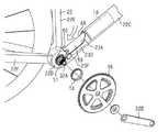
図1および図2に示されるとおり、自転車10は、自転車本体12、車輪14、駆動機構16、バッテリ18、および、自転車用コンポーネント40を含む。本実施形態において、自転車用コンポーネント40は、自転車用ドライブユニットである。
自転車本体12は、フレーム22、フレーム22に接続されるフロントフォーク24、および、フロントフォーク24にステム26Aを介して着脱可能に接続されるハンドルバー26Bを備えている。フロントフォーク24は、フレーム22に支持される。
As shown in FIGS. 1 and 2, thebicycle 10 includes abicycle body 12, wheels 14,drive mechanism 16,battery 18, andbicycle component 40. In this embodiment, thebicycle component 40 is a bicycle drive unit.
Thebicycle body 12 includes aframe 22, afront fork 24 connected to theframe 22, and ahandlebar 26B detachably connected to thefront fork 24 via astem 26A. Thefront fork 24 is supported by theframe 22.

フレーム22は、ヘッドチューブ22A、トップチューブ22B、ダウンチューブ22C、コンポーネント取付部22D、シートチューブ22E、シートステイ22F、および、チェーンステイ22Gを含む。コンポーネント取付部22Dは、ダウンチューブ22C、シートチューブ22E、および、シートステイ22Fにそれぞれ接続される。 Theframe 22 includes ahead tube 22A, atop tube 22B, adown tube 22C, acomponent mounting portion 22D, aseat tube 22E, aseat stay 22F, and achain stay 22G. Thecomponent mounting portion 22D is connected to thedown tube 22C, theseat tube 22E, and the seat stay 22F, respectively.

車輪14は、前輪28および後輪30を含む。前輪28の車軸28Aは、フロントフォーク24の端部に接続される。後輪30の車軸30Aは、フレーム22のリアエンドに接続される。 The wheels 14 include front wheels 28 and rear wheels 30. Theaxle 28A of the front wheel 28 is connected to the end of thefront fork 24. Theaxle 30A of the rear wheel 30 is connected to the rear end of theframe 22.

駆動機構16は、クランク32およびペダル34を含む。クランク32は、クランク軸32Aおよびクランクアーム32Bを含む。駆動機構16は、ペダル34に加えられた人力駆動力を後輪30に伝達する。駆動機構16は、自転車用コンポーネント40の出力部51に結合されるフロント回転体36を含む。フロント回転体36は、スプロケット、プーリーまたはベベルギアを含む。駆動機構16は、例えば、チェーン、ベルト、またはシャフトを介して、クランク32の回転を後輪30に結合されるリア回転体38に伝達するように構成される。リア回転体38は、スプロケット、プーリーまたはベベルギアを含む。リア回転体38と後輪30との間には、ワンウェイクラッチ(図示略)が設けられている。ワンウェイクラッチは、リア回転体38が前転した場合に、後輪30を前転させ、後輪30が後転した場合に、リア回転体38を後転させないように構成される。フロント回転体36は、複数のフロントスプロケットを含んでもよい。リア回転体38は、複数のリアスプロケットを含んでいてもよい。クランク軸32Aは、自転車用コンポーネント40に含まれていてもよい。 Thedrive mechanism 16 includes a crank 32 and apedal 34. Thecrank 32 includes acrankshaft 32A and acrank arm 32B. Thedrive mechanism 16 transmits the human-powered driving force applied to the pedal 34 to the rear wheels 30. Thedrive mechanism 16 includes a frontrotating body 36 coupled to anoutput section 51 of thebicycle component 40. The frontrotating body 36 includes a sprocket, a pulley or a bevel gear. Thedrive mechanism 16 is configured to transmit the rotation of thecrank 32 to the rearrotating body 38 coupled to the rear wheels 30 via, for example, a chain, belt, or shaft. The rearrotating body 38 includes a sprocket, a pulley or a bevel gear. A one-way clutch (not shown) is provided between the rearrotating body 38 and the rear wheel 30. The one-way clutch is configured so that the rear wheel 30 is rotated forward when the rearrotating body 38 is rotated forward, and the rearrotating body 38 is not rotated backward when the rear wheel 30 is rotated backward. The frontrotating body 36 may include a plurality of front sprockets. The rearrotating body 38 may include a plurality of rear sprockets. Thecrankshaft 32A may be included in thebicycle component 40.

図2に示されるとおり、コンポーネント取付部22Dは、フレーム22のうちのダウンチューブ22Cの下端部、シートチューブ22Eの下端部、およびチェーンステイ22Gの前端部にそれぞれ接続されている。コンポーネント取付部22Dは、自転車用コンポーネント40の少なくとも一部を収容可能に構成されている。コンポーネント取付部22Dは、ダウンチューブ22C、シートチューブ22Eおよびチェーンステイ22Gと一体に形成されることが好ましいが、溶接、接着などによって接続されていてもよい。フレーム22には、自転車用コンポーネント40およびバッテリ18をフレーム22に収容するための第1開口部23Aが設けられる。第1開口部23Aは、コンポーネント取付部22D、シートチューブ22Eのコンポーネント取付部22Dと接続される部分、および、ダウンチューブ22Cのコンポーネント取付部22Dと接続される部分に設けられ、自転車10の上方に向かって開口する。コンポーネント取付部22Dは、自転車10の左右方向に配置される第1側壁部23Dおよび第2側壁部23E(図4参照)と、自転車10の下方向に配置される底壁部23Fとを含む。第1側壁部23Dおよび第2側壁部23Eは、ダウンチューブ22C、シートチューブ22E、および、チェーンステイ22Gに連結される。底壁部23Fは、第1側壁部23Dおよび第2側壁部23Eの下端部に連結され、かつ、ダウンチューブ22Cおよびチェーンステイ22Gに連結される。第1開口部23Aの開口は、コンポーネント取付部22Dの側壁部23D,23Eのうちのクランク軸32Aが設けられる位置まで延びて形成されている。第1開口部23Aには、カバー23B(図4参照)が取り付けられることが好ましい。カバー23Bは、第1開口部23Aの開口を閉塞する。コンポーネント取付部22Dの底壁部23Fには、第2開口部23C(図6参照)が設けられる。自転車用コンポーネント40は、第1開口部23Aの開口に上側から挿入されて、フレーム22に取り付けられる。第2開口部23Cの開口は、自転車10の幅方向において、例えば第1側壁部23Dおよび第2側壁部23Eまで延びている。 As shown in FIG. 2, thecomponent mounting portion 22D is connected to the lower end portion of thedown tube 22C, the lower end portion of theseat tube 22E, and the front end portion of the chain stay 22G in theframe 22. Thecomponent mounting portion 22D is configured to accommodate at least a part of thebicycle component 40. Thecomponent mounting portion 22D is preferably formed integrally with thedown tube 22C, theseat tube 22E, and the chain stay 22G, but may be connected by welding, adhesion, or the like. Theframe 22 is provided with afirst opening 23A for accommodating thebicycle component 40 and thebattery 18 in theframe 22. Thefirst opening 23A is provided in thecomponent mounting portion 22D, the portion connected to thecomponent mounting portion 22D of theseat tube 22E, and the portion connected to thecomponent mounting portion 22D of thedown tube 22C, and is provided above thebicycle 10. Open towards. Thecomponent mounting portion 22D includes a firstside wall portion 23D and a secondside wall portion 23E (see FIG. 4) arranged in the left-right direction of thebicycle 10 and abottom wall portion 23F arranged in the downward direction of thebicycle 10. The firstside wall portion 23D and the secondside wall portion 23E are connected to thedown tube 22C, theseat tube 22E, and the chain stay 22G. Thebottom wall portion 23F is connected to the lower end portions of the firstside wall portion 23D and the secondside wall portion 23E, and is connected to thedown tube 22C and the chain stay 22G. The opening of thefirst opening 23A is formed so as to extend to a position where thecrankshaft 32A is provided among theside wall portions 23D and 23E of thecomponent mounting portion 22D. Acover 23B (see FIG. 4) is preferably attached to thefirst opening 23A. Thecover 23B closes the opening of thefirst opening 23A. Asecond opening 23C (see FIG. 6) is provided on thebottom wall portion 23F of thecomponent mounting portion 22D. Thebicycle component 40 is inserted into the opening of thefirst opening 23A from above and attached to theframe 22. The opening of thesecond side wall 23C extends in the width direction of thebicycle 10, for example, to thefirst side wall 23D and thesecond side wall 23E.

バッテリ18は、1または複数のバッテリセルを含む。バッテリセルは、充電池を含む。バッテリ18は、自転車10に搭載され、自転車用コンポーネント40に電力を供給する。バッテリ18は、フレーム22の内部に収容される。バッテリ18は、ダウンチューブ22Cに収容されることが好ましい。 Thebattery 18 includes one or more battery cells. The battery cell includes a rechargeable battery. Thebattery 18 is mounted on thebicycle 10 and supplies electric power to thebicycle component 40. Thebattery 18 is housed inside theframe 22. Thebattery 18 is preferably housed in thedown tube 22C.

自転車用コンポーネント40は、少なくとも一部がフレーム22の内部に配置される。本実施形態の自転車用コンポーネント40は、コンポーネント取付部22Dの内部空間に配置される。自転車用コンポーネント40の一端部は、コンポーネント取付部22Dのうち、シートステイ22Fおよびチェーンステイ22Gが接続される部分に設けられる。自転車用コンポーネント40の他端部には、バッテリ18が接続される。自転車用コンポーネント40と、バッテリ18とは、ダウンチューブ22Cの長手方向に沿って並んで配置される。 At least a part of thebicycle component 40 is arranged inside theframe 22. Thebicycle component 40 of the present embodiment is arranged in the internal space of thecomponent mounting portion 22D. One end of thebicycle component 40 is provided at a portion of thecomponent mounting portion 22D to which the seat stay 22F and the chain stay 22G are connected. Abattery 18 is connected to the other end of thebicycle component 40. Thebicycle component 40 and thebattery 18 are arranged side by side along the longitudinal direction of thedown tube 22C.

図3〜5に示されるとおり、自転車用コンポーネント40は、ハウジング42と、ハウジング42を自転車10に取り付けるための第1取付部44とを含む。自転車用コンポーネント40は、ハウジング42を自転車10のフレーム22に取り付けるための第2取付部46をさらに含む。ハウジング42は、自転車10のクランク軸32Aを支持する。ハウジング42は、クランク軸32Aを支持する支持部54を有する。ハウジング42は、モータ48の少なくとも一部を収容する。クランク軸32Aの軸方向の両端部は、それぞれハウジング42から外部に突出している。 As shown in FIGS. 3-5, thebicycle component 40 includes ahousing 42 and afirst attachment 44 for attaching thehousing 42 to thebicycle 10. Thebicycle component 40 further includes asecond attachment 46 for attaching thehousing 42 to theframe 22 of thebicycle 10. Thehousing 42 supports thecrankshaft 32A of thebicycle 10. Thehousing 42 has asupport portion 54 that supports thecrankshaft 32A. Thehousing 42 houses at least a portion of themotor 48. Both ends of thecrankshaft 32A in the axial direction project outward from thehousing 42, respectively.

モータ48は、ハウジング42に設けられる。ハウジング42は、少なくとも一部がフレーム22に収容可能に構成される。モータ48は、自転車用コンポーネント40に含まれる。モータ48は、自転車10の推進をアシストする。モータ48は、電気モータを含む。モータ48は、いわゆるブラシレスモータである。自転車用コンポーネント40は、減速機50および制御部52を含む。減速機50は、モータ48の回転を減速して出力する。一例では、モータ48の出力軸の軸方向は、クランク軸32Aの軸方向と直交する。この場合、減速機50は、モータ48の出力軸の回転をモータ48の出力軸と直交する方向の回転に変換することが好ましい。モータ48の出力軸の軸線と、クランク軸32Aの軸線とは、直交していてもよいし、オフセットしていてもよい。減速機50は、例えば、かさ歯車を含む。減速機50は、遊星歯車機構を更に含んでいてもよい。減速機50は、クランク軸32Aのまわりに配置される出力部51にモータ48の回転を出力する。モータ48の回転は、減速機50および出力部51を介してフロント回転体36に伝達される。 Themotor 48 is provided in thehousing 42. Thehousing 42 is configured so that at least a part thereof can be accommodated in theframe 22. Themotor 48 is included in thebicycle component 40. Themotor 48 assists the propulsion of thebicycle 10. Themotor 48 includes an electric motor. Themotor 48 is a so-called brushless motor. Thebicycle component 40 includes aspeed reducer 50 and acontrol unit 52. Thespeed reducer 50 reduces the rotation of themotor 48 and outputs the speed. In one example, the axial direction of the output shaft of themotor 48 is orthogonal to the axial direction of thecrankshaft 32A. In this case, it is preferable that thespeed reducer 50 converts the rotation of the output shaft of themotor 48 into the rotation in the direction orthogonal to the output shaft of themotor 48. The axis of the output shaft of themotor 48 and the axis of thecrankshaft 32A may be orthogonal or offset. Thespeed reducer 50 includes, for example, bevel gears. Thespeed reducer 50 may further include a planetary gear mechanism. Thespeed reducer 50 outputs the rotation of themotor 48 to theoutput unit 51 arranged around thecrankshaft 32A. The rotation of themotor 48 is transmitted to the frontrotating body 36 via thespeed reducer 50 and theoutput unit 51.

制御部52は、基板および駆動回路を含む。駆動回路は、インバータ回路を含み、バッテリ18からモータ48に供給される電力を制御する。制御部52は、予め定められる制御プログラムを実行する演算処理装置を含む。演算処理装置は、例えばCPU(Central Processing Unit)またはMPU(Micro Processing Unit)を含む。制御部52は、1または複数のマイクロコンピュータを含んでいてもよい。制御部52は、さらに記憶部およびタイマを含んでいてもよい。記憶部には、各種の制御プログラムおよび各種の制御処理に用いられる情報が記憶される。記憶部は、例えば不揮発性メモリおよび揮発性メモリを含む。 Thecontrol unit 52 includes a substrate and a drive circuit. The drive circuit includes an inverter circuit and controls the electric power supplied from thebattery 18 to themotor 48. Thecontrol unit 52 includes an arithmetic processing unit that executes a predetermined control program. The arithmetic processing unit includes, for example, a CPU (Central Processing Unit) or an MPU (Micro Processing Unit). Thecontrol unit 52 may include one or more microcomputers. Thecontrol unit 52 may further include a storage unit and a timer. Information used for various control programs and various control processes is stored in the storage unit. The storage unit includes, for example, a non-volatile memory and a volatile memory.

ハウジング42は、第1収容部56および第2収容部58を含む。第1収容部56は、筒状に形成される部分を有する。第1収容部56は、モータ48、減速機50の一部、および、制御部52を収容する。第1収容部56の長手方向の一方の端部56Aには、バッテリ18と制御部52とを電気的に接続するための電気端子が設けられることが好ましい。第2収容部58は、クランク軸32Aの軸線方向から見た形状が、円盤状となるように形成されることが好ましい。第2収容部58は、第1ハウジング60の長手方向の他方の端部56Bと接続されている。第1収容部56および第2収容部58は、一体で形成されていてもよく、別体で形成されていてもよい。第1収容部56の少なくとも一部と第2収容部58の少なくとも一部とは、一体で形成されていてもよい。支持部54は、第2収容部58に設けられる。支持部54は、クランク軸32Aを回転可能に支持する。 Thehousing 42 includes a firstaccommodating portion 56 and a secondaccommodating portion 58. The firstaccommodating portion 56 has a portion formed in a tubular shape. The firstaccommodating unit 56 accommodates themotor 48, a part of thespeed reducer 50, and thecontrol unit 52. It is preferable that oneend 56A in the longitudinal direction of the firstaccommodating portion 56 is provided with an electric terminal for electrically connecting thebattery 18 and thecontrol portion 52. The secondaccommodating portion 58 is preferably formed so that the shape of thecrankshaft 32A seen from the axial direction is a disk shape. The secondaccommodating portion 58 is connected to theother end 56B in the longitudinal direction of thefirst housing 60. The firstaccommodating portion 56 and the secondaccommodating portion 58 may be integrally formed or may be formed separately. At least a part of the firstaccommodating portion 56 and at least a part of the secondaccommodating portion 58 may be integrally formed. Thesupport portion 54 is provided in the secondaccommodating portion 58. Thesupport portion 54 rotatably supports thecrankshaft 32A.

図3および図7に示されるとおり、ハウジング42は、第1ハウジング60および第2ハウジング62を含んで構成される。第1ハウジング60は、クランク軸32Aの軸方向において、ハウジング42の一方の側面部を含む。第2ハウジング62は、クランク軸32Aの軸方向において、ハウジング42の他方の側面部を含む。ハウジング42は、第1ハウジング60と第2ハウジング62とが組み付けられることによって内部に収容空間が形成される。第1ハウジング60と第2ハウジング62とは、例えばボルトによって相互に固定される。 As shown in FIGS. 3 and 7, thehousing 42 includes afirst housing 60 and asecond housing 62. Thefirst housing 60 includes one side surface portion of thehousing 42 in the axial direction of thecrankshaft 32A. Thesecond housing 62 includes the other side surface portion of thehousing 42 in the axial direction of thecrankshaft 32A. A storage space is formed inside thehousing 42 by assembling thefirst housing 60 and thesecond housing 62. Thefirst housing 60 and thesecond housing 62 are fixed to each other by, for example, bolts.

自転車用コンポーネント40は、第1軸受64A、第2軸受64B、第1ワンウェイクラッチ66A、および、第2ワンウェイクラッチ66Bをさらに含む。第1軸受64Aは、第1ハウジング60とクランク軸32Aとの間に設けられて、クランク軸32Aを第1ハウジング60に対して回転可能に支持する。第2軸受64Bは、第2ハウジング62と出力部51との間に設けられて、出力部51を第2ハウジング62に対して回転可能に支持する。第1軸受64Aおよび第2軸受64Bは、クランク軸32Aの軸方向に離間して設けられる。第1軸受64Aは、ハウジング42のうちのクランク軸32Aの軸方向の一方の端部寄りに設けられる。第2軸受64Bは、ハウジング42のうちのクランク軸32Aの軸方向の他方の端部寄りに設けられる。 Thebicycle component 40 further includes afirst bearing 64A, asecond bearing 64B, a first one-way clutch 66A, and a second one-way clutch 66B. Thefirst bearing 64A is provided between thefirst housing 60 and thecrankshaft 32A, and rotatably supports thecrankshaft 32A with respect to thefirst housing 60. Thesecond bearing 64B is provided between thesecond housing 62 and theoutput unit 51, and rotatably supports theoutput unit 51 with respect to thesecond housing 62. Thefirst bearing 64A and thesecond bearing 64B are provided apart from each other in the axial direction of thecrankshaft 32A. Thefirst bearing 64A is provided near one end of thecrankshaft 32A in thehousing 42 in the axial direction. Thesecond bearing 64B is provided near the other end of thecrankshaft 32A in thehousing 42 in the axial direction.

出力部51は、クランク軸32Aと同軸に設けられる。出力部51は、筒状に形成されている。出力部51は、クランク軸32Aの外周面の一部を覆う。出力部51は、クランク軸32Aの軸方向の他方側で、ハウジング42の外部に突出している。クランク軸32Aの軸方向の他方の端部は、出力部51よりもクランク軸32Aの軸方向の他方まで延びている。 Theoutput unit 51 is provided coaxially with thecrankshaft 32A. Theoutput unit 51 is formed in a tubular shape. Theoutput unit 51 covers a part of the outer peripheral surface of thecrankshaft 32A. Theoutput unit 51 projects to the outside of thehousing 42 on the other side of thecrankshaft 32A in the axial direction. The other end of thecrankshaft 32A in the axial direction extends beyond theoutput section 51 to the other end of thecrankshaft 32A in the axial direction.

第1ワンウェイクラッチ66Aは、クランク軸32Aと出力部51との間に設けられる。第1ワンウェイクラッチ66Aは、出力部51のうちのクランク軸32Aの軸方向の一方に近い端部に設けられる。第1ワンウェイクラッチ66Aは、一部がクランク軸32Aおよび出力部51の少なくとも一方と一体に形成されていてもよい。例えば第1ワンウェイクラッチ66Aはローラクラッチを含む。この場合、第1ワンウェイクラッチ66Aの内輪は、クランク軸32Aと一体に形成されてもよく、第1ワンウェイクラッチ66Aの外輪は、出力部51と一体に形成されてもよい。 The first one-way clutch 66A is provided between thecrankshaft 32A and theoutput unit 51. The first one-way clutch 66A is provided at an end portion of theoutput portion 51 near one of thecrankshafts 32A in the axial direction. A part of the first one-way clutch 66A may be integrally formed with at least one of thecrankshaft 32A and theoutput unit 51. For example, the first one-way clutch 66A includes a roller clutch. In this case, the inner ring of the first one-way clutch 66A may be formed integrally with thecrankshaft 32A, and the outer ring of the first one-way clutch 66A may be formed integrally with theoutput unit 51.

出力部51のうち、クランク軸32Aの軸方向の他方に近い端部と、クランク軸32Aとの間には、第3軸受64Cが設けられる。第3軸受64Cは、例えばスリーブまたはニードルベアリングを含む。クランク軸32Aは、第3軸受64Cおよび出力部51を介して、第2軸受64Bに支持される。第2軸受64Bと第3軸受64Cとは、クランク軸32Aに垂直な方向において少なくとも一部が重なる位置に設けられることが好ましい。 Athird bearing 64C is provided between the end of theoutput portion 51 near the other end of thecrankshaft 32A in the axial direction and thecrankshaft 32A. Thethird bearing 64C includes, for example, a sleeve or needle bearing. Thecrankshaft 32A is supported by thesecond bearing 64B via thethird bearing 64C and theoutput unit 51. It is preferable that thesecond bearing 64B and thethird bearing 64C are provided at positions where at least a part of thesecond bearing 64B and thethird bearing 64C overlap in the direction perpendicular to thecrankshaft 32A.

第1ワンウェイクラッチ66Aは、クランク軸32Aの第1回転方向の回転を出力部51に伝達し、出力部51の第1回転方向の回転をクランク軸32Aに伝達しない。第2ワンウェイクラッチ66Bは、出力部51と減速機50とを接続する歯車51Aとの間に設けられる。第2ワンウェイクラッチ66Bは、モータ48の第1回転方向の回転を出力部51に伝達し、出力部51の第1回転方向の回転をモータ48に伝達しない。クランク軸32Aの第1回転方向は、自転車10を前進させる場合に、クランク軸32Aを回転させる方向である。出力部51の第1回転方向は、自転車10を前進させる場合に、出力部51を回転させる方向である。モータ48の第1回転方向は、モータ48が自転車10の前進を推進する場合に、モータ48が回転する方向である。出力部51およびハウジング42には、出力部51に伝達される回転力を検出するためのトルクセンサ(図示しない)が設けられる。トルクセンサは、例えばひずみセンサまたは磁歪センサを含む。制御部52は、トルクセンサの出力に応じて、モータ48を制御する。 The first one-way clutch 66A transmits the rotation of thecrankshaft 32A in the first rotation direction to theoutput unit 51, and does not transmit the rotation of theoutput unit 51 in the first rotation direction to thecrankshaft 32A. The second one-way clutch 66B is provided between thegear 51A that connects theoutput unit 51 and thespeed reducer 50. The second one-way clutch 66B transmits the rotation of themotor 48 in the first rotation direction to theoutput unit 51, and does not transmit the rotation of theoutput unit 51 in the first rotation direction to themotor 48. The first rotation direction of thecrankshaft 32A is the direction in which thecrankshaft 32A is rotated when thebicycle 10 is advanced. The first rotation direction of theoutput unit 51 is a direction in which theoutput unit 51 is rotated when thebicycle 10 is advanced. The first rotation direction of themotor 48 is the direction in which themotor 48 rotates when themotor 48 propels thebicycle 10 to move forward. Theoutput unit 51 and thehousing 42 are provided with a torque sensor (not shown) for detecting the rotational force transmitted to theoutput unit 51. Torque sensors include, for example, strain sensors or magnetostrictive sensors. Thecontrol unit 52 controls themotor 48 according to the output of the torque sensor.

図4に示されるとおり、ハウジング42は、少なくとも一部がフレーム22に収容可能に構成される。具体的には、ハウジング42は、第1収容部56の少なくとも一部がコンポーネント取付部22Dのうちのダウンチューブ22Cに接続されている側の部分に収容され、第2収容部58がコンポーネント取付部22Dのうちのシートチューブ22Eおよびチェーンステイ22Gに接続されている側の部分に収容される。ハウジング42は、モータ48の回転軸線がダウンチューブ22Cの長手方向に沿うように、モータ48の回転軸線に平行な方向と、クランク軸の回転軸心に平行な方向とは、互いに直交することが好ましい。フレーム22に取り付けられている。コンポーネント取付部22Dのうち第1収容部56が収容されている部分は、ダウンチューブ22Cに含まれていてもよい。 As shown in FIG. 4, thehousing 42 is configured so that at least a part thereof can be accommodated in theframe 22. Specifically, thehousing 42 is housed in a portion of thecomponent mounting portion 22D where at least a part of the firstaccommodating portion 56 is connected to thedown tube 22C, and the secondaccommodating portion 58 is a component mounting portion. It is housed in the side portion of 22D connected to theseat tube 22E and the chain stay 22G. In thehousing 42, the direction parallel to the rotation axis of themotor 48 and the direction parallel to the rotation axis of the crankshaft may be orthogonal to each other so that the rotation axis of themotor 48 is along the longitudinal direction of thedown tube 22C. preferable. It is attached to theframe 22. The portion of thecomponent mounting portion 22D in which the firstaccommodating portion 56 is accommodated may be included in thedown tube 22C.

図4および図7に示されるとおり、第1取付部44は、第1部材68と、第2部材70と、を含む。第1取付部44は、支持部54から独立してハウジング42に設けられる。第1取付部44と第2取付部46とは、所定方向において相互に離間して設けられる。所定方向は、クランク軸32Aの軸方向Cに平行する。第1取付部44は、クランク軸32Aの軸方向Cにおけるハウジング42の第1側面部42Xに設けられる。第2取付部46は、クランク軸32Aの軸方向Cにおいて、ハウジング42の第1側面部42Xとは反対側の第2側面部42Yに設けられる。第1側面部42Xは、クランク軸32Aの軸方向Cにおける第2収容部58の一方の側面部を含む。第2側面部42Yは、クランク軸32Aの軸方向Cにおける第2収容部58の他方の側面部を含む。 As shown in FIGS. 4 and 7, the first mountingportion 44 includes afirst member 68 and asecond member 70. The first mountingportion 44 is provided on thehousing 42 independently of the supportingportion 54. The first mountingportion 44 and the second mountingportion 46 are provided so as to be separated from each other in a predetermined direction. The predetermined direction is parallel to the axial direction C of thecrankshaft 32A. The first mountingportion 44 is provided on the firstside surface portion 42X of thehousing 42 in the axial direction C of thecrankshaft 32A. The second mountingportion 46 is provided on the secondside surface portion 42Y on the side opposite to the firstside surface portion 42X of thehousing 42 in the axial direction C of thecrankshaft 32A. The firstside surface portion 42X includes one side surface portion of the secondaccommodating portion 58 in the axial direction C of thecrankshaft 32A. The secondside surface portion 42Y includes the other side surface portion of the secondaccommodating portion 58 in the axial direction C of thecrankshaft 32A.

第1部材68は、円環状に形成される。第1部材68は、第1方向に延びる第1孔68Aを含む。第1孔68Aは、クランク軸32Aが貫通する貫通孔を含む。第1部材68は、貫通孔を有する。第1方向は、クランク軸32Aの軸方向Cと一致する。第1部材68には、雄ねじ68Bが形成される。雄ねじ68Bは、第1部材68の外周部に形成されている。第1部材68は、第1方向およびクランク軸32Aの軸方向Cに交差する方向において、ハウジング42を支持するように構成される。ハウジング42は、第1部材68の第1孔68Aに挿入される挿入部分42Aを含む。挿入部分42Aは、支持部54に含まれることが好ましい。第1部材68は、内周部68Dが挿入部分42Aを支持する。第1部材68の挿入部分42Aに挿入される部分の内径は、挿入部分42Aの外径よりもわずかに大きいことが好ましい。 Thefirst member 68 is formed in an annular shape. Thefirst member 68 includes afirst hole 68A extending in the first direction. Thefirst hole 68A includes a through hole through which thecrankshaft 32A penetrates. Thefirst member 68 has a through hole. The first direction coincides with the axial direction C of thecrankshaft 32A. Amale screw 68B is formed on thefirst member 68. Themale screw 68B is formed on the outer peripheral portion of thefirst member 68. Thefirst member 68 is configured to support thehousing 42 in a first direction and in a direction intersecting the axial direction C of thecrankshaft 32A. Thehousing 42 includes aninsertion portion 42A that is inserted into thefirst hole 68A of thefirst member 68. Theinsertion portion 42A is preferably included in thesupport portion 54. In thefirst member 68, the innerperipheral portion 68D supports theinsertion portion 42A. It is preferable that the inner diameter of the portion of thefirst member 68 to be inserted into theinsertion portion 42A is slightly larger than the outer diameter of theinsertion portion 42A.

第2部材70は、円環状に形成される。第2部材70の少なくとも一部は、ハウジング42とフレーム22との間に設けられる。第2部材70の少なくとも一部は、第1部材68とフレーム22との間に設けられる。第2部材70は、第1方向に交差する方向およびクランク軸32Aの軸方向Cにおいてフレーム22の一部に接触するように構成される。第2部材70は、コンポーネント取付部22Dの第2側壁部23Eに接触する。第2部材70は、第1方向に延びる孔70Aを含む。第2部材70には、第1部材68の雄ねじ68Bに結合される雌ねじ70Bが形成される。雌ねじ70Bは、第2部材70の内周部に形成されている。図8に示されるとおり、第2部材70の側面部70Dには、フレーム係合部70Eが形成される。フレーム係合部70Eは、クランク軸32Aの軸方向に突出する凸部70Fを有する。凸部70Fは、クランク軸32Aの周方向に間隔を開けて設けられる。フレーム22には、フレーム係合部70Eの凸部70Fと対応する凹部22Xが設けられる。フレーム係合部70Eの凸部70Fがフレーム22の凹部22Xに嵌まり込むことによって、第2部材70のフレーム22に対する中心軸周りの回転が規制される。第2部材70の内周側において、各凸部70Fの端部は環状に連結されていてもよい。 Thesecond member 70 is formed in an annular shape. At least a part of thesecond member 70 is provided between thehousing 42 and theframe 22. At least a part of thesecond member 70 is provided between thefirst member 68 and theframe 22. Thesecond member 70 is configured to come into contact with a part of theframe 22 in the direction intersecting the first direction and in the axial direction C of thecrankshaft 32A. Thesecond member 70 comes into contact with the secondside wall portion 23E of thecomponent mounting portion 22D. Thesecond member 70 includes ahole 70A extending in the first direction. Thesecond member 70 is formed with afemale screw 70B that is coupled to themale screw 68B of thefirst member 68. Thefemale screw 70B is formed on the inner peripheral portion of thesecond member 70. As shown in FIG. 8, aframe engaging portion 70E is formed on theside surface portion 70D of thesecond member 70. Theframe engaging portion 70E has aconvex portion 70F protruding in the axial direction of thecrankshaft 32A. Theconvex portions 70F are provided at intervals in the circumferential direction of thecrankshaft 32A. Theframe 22 is provided with aconcave portion 22X corresponding to theconvex portion 70F of theframe engaging portion 70E. By fitting theconvex portion 70F of theframe engaging portion 70E into theconcave portion 22X of theframe 22, the rotation of thesecond member 70 with respect to theframe 22 is restricted. On the inner peripheral side of thesecond member 70, the ends of theconvex portions 70F may be connected in an annular shape.

第1部材68は、ハウジング42を押圧するように構成される。具体的には、第1部材68は、第2部材70に結合して移動する第1方向の第1端面68Cがハウジング42を押圧するように構成される。第1部材68は、第2部材70にねじ込まれる第1方向の第1端面68Cがハウジング42を押圧するように構成される。第2部材70は、フレーム22を押圧するように構成される。具体的には、第2部材70の側面部70Dのうち、凸部70Fの間の部分がフレーム22のうちのハウジング42の第2側面部42Yと対向する部分と接触可能に構成される。 Thefirst member 68 is configured to press thehousing 42. Specifically, thefirst member 68 is configured such that thefirst end surface 68C in the first direction, which is coupled to thesecond member 70 and moves, presses thehousing 42. Thefirst member 68 is configured such that thefirst end surface 68C in the first direction screwed into thesecond member 70 presses thehousing 42. Thesecond member 70 is configured to press theframe 22. Specifically, the portion of theside surface portion 70D of thesecond member 70 between theconvex portions 70F is configured to be in contact with the portion of theframe 22 facing the secondside surface portion 42Y of thehousing 42.

第1部材68および第2部材70の少なくとも一方は、工具を係合可能な工具係合部72をさらに含む。工具係合部72は、第1部材68の内周部68Dまたは外周部68Eの少なくとも一方に形成されることが好ましい。本実施形態では、工具係合部72は、第1部材68の内周部68Dに形成される。工具係合部72は、クランク軸32Aに関して径方向に突出する凸部および凹む凹部を含む。凸部および凹部は、クランク軸32Aまわりの周方向において所定の間隔をあけて、交互に配置されることが好ましい。 At least one of thefirst member 68 and thesecond member 70 further includes atool engaging portion 72 to which the tool can be engaged. Thetool engaging portion 72 is preferably formed on at least one of the innerperipheral portion 68D and the outerperipheral portion 68E of thefirst member 68. In the present embodiment, thetool engaging portion 72 is formed on the innerperipheral portion 68D of thefirst member 68. Thetool engaging portion 72 includes a convex portion and a concave concave portion that protrude in the radial direction with respect to thecrankshaft 32A. It is preferable that the convex portions and the concave portions are alternately arranged at predetermined intervals in the circumferential direction around thecrankshaft 32A.

図5および図7に示されるとおり、第2取付部46は、ハウジング42に形成されるねじ孔42Bと、第1連結部材74と、を含む。
第1連結部材74は、円環状に形成される。第1連結部材74は、第1方向に延びる孔74Aを含む。第1連結部材74は、フレーム22を貫通してねじ孔42Bに連結される。第1連結部材74は、コンポーネント取付部22Dの第1側壁部23Dを貫通する。ねじ孔42Bには、雌ねじが形成されている。第1連結部材74は、ねじ孔42Bの雌ねじに結合するための雄ねじ74Bを含む。第1連結部材74の外周部は、雄ねじ74Bが形成される部分と、雄ねじ74Bが形成される部分よりも径方向の外側に延びる側面部74Cとを含む。第1連結部材74は、フレーム22を貫通してねじ孔42Bに連結される連結部材に相当する。側面部74Cは、ハウジング42との間にフレーム22を挟むように構成される。側面部74Cの外周部および内周部の少なくとも一方に工具を係合する工具係合部を形成することが好ましい。工具係合部は、例えば第1連結部材74の径方向の突出または凹む凹凸形状を含む。ねじ孔42Bが雌ねじではなく雄ねじを含むようにしてもよい。この場合、第1連結部材74の外周部の雄ねじを省略して、第1連結部材74の内周部に、ねじ孔42Bに結合される雌ねじが形成されてもよい。
As shown in FIGS. 5 and 7, the second mountingportion 46 includes ascrew hole 42B formed in thehousing 42 and a first connectingmember 74.
The first connectingmember 74 is formed in an annular shape. The first connectingmember 74 includes ahole 74A extending in the first direction. The first connectingmember 74 penetrates theframe 22 and is connected to thescrew hole 42B. The first connectingmember 74 penetrates the firstside wall portion 23D of thecomponent mounting portion 22D. A female screw is formed in thescrew hole 42B. The first connectingmember 74 includes amale screw 74B for connecting to the female screw of thescrew hole 42B. The outer peripheral portion of the first connectingmember 74 includes a portion where themale screw 74B is formed and aside surface portion 74C extending radially outward from the portion where themale screw 74B is formed. The first connectingmember 74 corresponds to a connecting member that penetrates theframe 22 and is connected to thescrew hole 42B. Theside surface portion 74C is configured to sandwich theframe 22 with thehousing 42. It is preferable to form a tool engaging portion for engaging the tool on at least one of the outer peripheral portion and the inner peripheral portion of theside surface portion 74C. The tool engaging portion includes, for example, a concave-convex shape in which the first connectingmember 74 protrudes or is recessed in the radial direction. Thescrew hole 42B may include a male screw instead of a female screw. In this case, the male screw on the outer peripheral portion of the first connectingmember 74 may be omitted, and a female screw to be coupled to thescrew hole 42B may be formed on the inner peripheral portion of the first connectingmember 74.

自転車用コンポーネント40は、ハウジング42をフレーム22に取り付けるための第3取付部76をさらに含むことが好ましい。図6に示されるとおり、第3取付部76は、クランク軸32Aの軸方向に交差する方向において、ハウジング42に設けられる。第3取付部76は、ねじ孔78と、第2連結部材80と、を含む。ねじ孔78は、ハウジング42に形成される。第2連結部材80は、フレーム22を貫通してねじ孔78に連結される。第2連結部材80は、ボルトを含む。第2連結部材80は、複数のねじ孔と、複数のボルトとを含んで構成されてもよい。この場合、複数のねじ孔は、クランク軸32Aの軸方向に間隔を開けて設けられることが好ましい。 Thebicycle component 40 preferably further includes a third mountingportion 76 for mounting thehousing 42 to theframe 22. As shown in FIG. 6, the third mountingportion 76 is provided on thehousing 42 in a direction intersecting the axial direction of thecrankshaft 32A. The third mountingportion 76 includes ascrew hole 78 and a second connectingmember 80. The screw holes 78 are formed in thehousing 42. The second connectingmember 80 penetrates theframe 22 and is connected to thescrew hole 78. The second connectingmember 80 includes a bolt. The second connectingmember 80 may be configured to include a plurality of screw holes and a plurality of bolts. In this case, it is preferable that the plurality of screw holes are provided at intervals in the axial direction of thecrankshaft 32A.

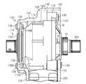
図9に示されるとおり、第1取付部44は、ハウジング42とフレーム22とが相互に離反する方向の力を、ハウジング42とフレーム22と付与するように構成される。第1取付部44は、クランク軸32Aの軸方向Cにおいて、ハウジング42とフレーム22とが相互に離反する方向の力を、ハウジング42とフレーム22とに付与するように構成される。具体的には、第1部材68は、第1端面68Cがハウジング42を押圧することによってハウジング42に第2取付部46側に向かう方向A1の力を付与する。第2部材70は、第2部材70の軸力によってフレーム22に方向A1とは反対の方向A2に向かう力を付与する。 As shown in FIG. 9, the first mountingportion 44 is configured to apply a force in a direction in which thehousing 42 and theframe 22 are separated from each other to thehousing 42 and theframe 22. The first mountingportion 44 is configured to apply a force in the axial direction C of thecrankshaft 32A in a direction in which thehousing 42 and theframe 22 are separated from each other to thehousing 42 and theframe 22. Specifically, thefirst member 68 applies a force in the direction A1 toward the second mountingportion 46 side to thehousing 42 by thefirst end surface 68C pressing thehousing 42. Thesecond member 70 applies a force to theframe 22 in the direction A2 opposite to the direction A1 by the axial force of thesecond member 70.

第2取付部46は、ハウジング42とフレーム22とが相互に近付く方向の力を、ハウジング42とフレーム22とに付与するように構成される。第2取付部46は、クランク軸32Aの軸方向Cにおいて、ハウジング42とフレーム22とが相互に近付く方向の力を、ハウジング42とフレーム22とに付与するように構成される。具体的には、第1連結部材74は、第1連結部材74の軸力によってハウジング42に第1取付部44側に向かう方向B1の力を付与する。第1連結部材74は、第1連結部材74の軸力によってフレーム22に方向B1とは反対の方向B2に向かう力を付与する。 The second mountingportion 46 is configured to apply a force in a direction in which thehousing 42 and theframe 22 approach each other to thehousing 42 and theframe 22. The second mountingportion 46 is configured to apply a force in the axial direction C of thecrank shaft 32A in a direction in which thehousing 42 and theframe 22 approach each other to thehousing 42 and theframe 22. Specifically, the first connectingmember 74 applies a force in the direction B1 toward the first mountingportion 44 side to thehousing 42 by the axial force of the first connectingmember 74. The first connectingmember 74 applies a force to theframe 22 in the direction B2 opposite to the direction B1 by the axial force of the first connectingmember 74.

ハウジング42は、第1ハウジング60が第2ハウジング62側に押される。このため、第1ハウジング60と第2ハウジング62との組み付け部が離間しにくくなる。このため、ハウジング42に変形または隙間が生じにくくなる。 In thehousing 42, thefirst housing 60 is pushed toward thesecond housing 62. Therefore, it becomes difficult for the assembled portion between thefirst housing 60 and thesecond housing 62 to be separated from each other. Therefore, thehousing 42 is less likely to be deformed or have a gap.

(第2実施形態)
図10を参照して、第2実施形態の自転車用コンポーネント40について説明する。第2実施形態の自転車用コンポーネント40は、フレーム22に対する取付姿勢が第1実施形態の自転車用コンポーネント40とは異なる点以外は、第1実施形態の自転車用コンポーネント40と同様であるので、第1実施形態と共通する構成については、第1実施形態と同一の符号を付し、重複する説明を省略する。本実施形態では、ハウジング42の第1収容部56の少なくとも一部が、シートチューブ22Eに収容される。
(Second Embodiment)
Thebicycle component 40 of the second embodiment will be described with reference to FIG. Thebicycle component 40 of the second embodiment is the same as thebicycle component 40 of the first embodiment except that the mounting posture with respect to theframe 22 is different from that of thebicycle component 40 of the first embodiment. The same reference numerals as those of the first embodiment will be given to the configurations common to the embodiments, and duplicate description will be omitted. In the present embodiment, at least a part of the firstaccommodating portion 56 of thehousing 42 is accommodated in theseat tube 22E.

図10に示されるとおり、ハウジング42の第1収容部56の少なくとも一部がシートチューブ22Eに収容され、第2収容部58がコンポーネント取付部22Dに収容される。フレーム22には、自転車用コンポーネント40をフレーム22に収容するための第1開口部90Aが設けられる。第1開口部90Aは、コンポーネント取付部22D、シートチューブ22Eのうちのコンポーネント取付部22Dと接続される部分、および、ダウンチューブ22Cのうちのコンポーネント取付部22Dと接続される部分に設けられる。第1開口部90Aは、自転車10の前方および上方に向かって開口する。第1開口部90Aには、カバー(図示略)が取り付けられることが好ましい。カバーは、第1開口部90Aの開口を閉塞する。 As shown in FIG. 10, at least a part of the firstaccommodating portion 56 of thehousing 42 is accommodated in theseat tube 22E, and the secondaccommodating portion 58 is accommodated in thecomponent mounting portion 22D. Theframe 22 is provided with afirst opening 90A for accommodating thebicycle component 40 in theframe 22. Thefirst opening 90A is provided in acomponent mounting portion 22D, a portion of theseat tube 22E connected to thecomponent mounting portion 22D, and a portion of thedown tube 22C connected to thecomponent mounting portion 22D. Thefirst opening 90A opens toward the front and upward of thebicycle 10. A cover (not shown) is preferably attached to thefirst opening 90A. The cover closes the opening of thefirst opening 90A.

自転車用コンポーネント40は、少なくとも一部がフレーム22の内部に配置される。本実施形態の自転車用コンポーネント40の少なくとも一部は、シートチューブ22Eの内部に配置される。具体的には、第1収容部56の一部がシートチューブ22Eに収容され、第2収容部58がコンポーネント取付部22Dに収容される。第2収容部58の外周部には、制御部52(図3参照)と接続される電気端子が設けられることが好ましい。第2収容部58の外周部に設けられる電気端子は、ダウンチューブ22Cの内部に配置されるバッテリ18と接続される。モータ48の回転軸線が、シートチューブ22Eの長手方向に実質的に沿うように、ハウジング42がフレーム22に取り付けられている。 At least a part of thebicycle component 40 is arranged inside theframe 22. At least a portion of thebicycle component 40 of this embodiment is located inside theseat tube 22E. Specifically, a part of the firstaccommodating portion 56 is accommodated in theseat tube 22E, and the secondaccommodating portion 58 is accommodated in thecomponent mounting portion 22D. It is preferable that an electric terminal connected to the control unit 52 (see FIG. 3) is provided on the outer peripheral portion of the secondaccommodating unit 58. The electric terminal provided on the outer peripheral portion of the secondaccommodating portion 58 is connected to thebattery 18 arranged inside thedown tube 22C. Thehousing 42 is attached to theframe 22 so that the rotation axis of themotor 48 is substantially along the longitudinal direction of theseat tube 22E.

(第3実施形態)
図11および図12を参照して、第3実施形態の自転車用コンポーネント92について説明する。第3実施形態の自転車用コンポーネント92は、フレーム22の外部に設けられる点以外は第1実施形態の自転車用コンポーネント40と同様であるので、第1実施形態と共通する構成については、第1実施形態と同一の符号を付し、重複する説明を省略する。
(Third Embodiment)
Thebicycle component 92 of the third embodiment will be described with reference to FIGS. 11 and 12. Thebicycle component 92 of the third embodiment is the same as thebicycle component 40 of the first embodiment except that it is provided outside theframe 22, and therefore, the configuration common to the first embodiment is the first embodiment. The same reference numerals as those in the form will be attached, and duplicate description will be omitted.

図11に示されるとおり、フレーム22には、自転車用コンポーネント92を取り付けるためのブラケット100が設けられる。ブラケット100は、フレーム22のうちのダウンチューブ22Cの下端部、シートチューブ22Eの下端部、およびチェーンステイ22Gの前端部にそれぞれ接続されている。 As shown in FIG. 11, theframe 22 is provided with abracket 100 for attaching thebicycle component 92. Thebracket 100 is connected to the lower end of thedown tube 22C, the lower end of theseat tube 22E, and the front end of the chain stay 22G in theframe 22, respectively.

自転車用コンポーネント92は、少なくとも一部がフレーム22の内部に配置される。本実施形態の自転車用コンポーネント92は、一部がブラケット100の内部に配置される。 At least a part of thebicycle component 92 is arranged inside theframe 22. A part of thebicycle component 92 of the present embodiment is arranged inside thebracket 100.

自転車用コンポーネント92は、ハウジング94と、ハウジング94を自転車10に取り付けるための第1取付部96とを含む。自転車用コンポーネント92は、ハウジング94を自転車10のフレーム22に取り付けるための第2取付部98をさらに含む。ハウジング94は、自転車10のクランク軸32Aを支持する。ハウジング94は、クランク軸32Aを支持する支持部54を有する。ハウジング94は、モータ48の少なくとも一部を収容する。 Thebicycle component 92 includes ahousing 94 and a first mountingportion 96 for mounting thehousing 94 to thebicycle 10. Thebicycle component 92 further includes a second mountingportion 98 for mounting thehousing 94 to theframe 22 of thebicycle 10. Thehousing 94 supports thecrankshaft 32A of thebicycle 10. Thehousing 94 has asupport portion 54 that supports thecrankshaft 32A. Thehousing 94 houses at least a portion of themotor 48.

モータ48は、ハウジング94に設けられる。ハウジング94は、少なくとも一部がフレーム22に収容可能に構成される。自転車用コンポーネント92は、モータ48、減速機(図示略)、および、制御部(図示略)を含む。一例では、モータ48の出力軸の軸方向は、クランク軸32Aの軸方向Cに平行する。減速機は、モータ48の回転を減速して出力する。減速機は、例えば歯車機構を含む。減速機は、クランク軸32Aのまわりに配置される出力部にモータ48の回転を出力する。モータ48の回転は、減速機および出力部を介してフロント回転体36(図1参照)に伝達される。 Themotor 48 is provided in thehousing 94. Thehousing 94 is configured so that at least a part thereof can be accommodated in theframe 22. Thebicycle component 92 includes amotor 48, a speed reducer (not shown), and a control unit (not shown). In one example, the axial direction of the output shaft of themotor 48 is parallel to the axial direction C of thecrankshaft 32A. The speed reducer reduces the rotation of themotor 48 and outputs the speed. The speed reducer includes, for example, a gear mechanism. The speed reducer outputs the rotation of themotor 48 to an output unit arranged around thecrankshaft 32A. The rotation of themotor 48 is transmitted to the front rotating body 36 (see FIG. 1) via the speed reducer and the output unit.

ハウジング94は、少なくとも一部がフレーム22に収容可能に構成される。具体的には、ハウジング94は、ハウジング94の外周部から突出する凸部94Aがブラケット100に嵌め込まれる。ハウジング94は、複数の凸部94Aを含むことが好ましい。第1取付部96および第2取付部98は、複数の凸部94Aに選択的に設けられることが好ましい。 Thehousing 94 is configured so that at least a part thereof can be accommodated in theframe 22. Specifically, in thehousing 94, aconvex portion 94A protruding from the outer peripheral portion of thehousing 94 is fitted into thebracket 100. Thehousing 94 preferably includes a plurality ofprotrusions 94A. It is preferable that the first mountingportion 96 and the second mountingportion 98 are selectively provided on the plurality ofconvex portions 94A.

第1取付部96は、第1部材102と、第2部材70と、を含む。第1取付部96は、支持部54(図11参照)から独立してハウジング94に設けられる。第1取付部96は、クランク軸32Aの軸方向Cにおけるハウジング94の第1側面部94Xに設けられる。第1取付部96と第2取付部98とは、所定方向において相互に離間して設けられる。所定方向は、クランク軸32Aの軸方向Cに平行する。第1取付部96は、クランク軸32Aの軸方向Cにおけるハウジング94の第1側面部94X、またはハウジング94のクランク軸32Aの軸方向C周りの外周部のうち、第2取付部98よりも第1側面部94X寄りの部分に設けられる。第2取付部98は、クランク軸32Aの軸方向Cにおいて、ハウジング94の第1側面部94Xとは反対側の第2側面部94Y、またはハウジングのクランク軸32Aの軸方向C周りの外周部のうち、第1取付部96よりも第2側面部94Y寄りの部分に設けられる。 The first mountingportion 96 includes afirst member 102 and asecond member 70. The first mountingportion 96 is provided in thehousing 94 independently of the supporting portion 54 (see FIG. 11). The first mountingportion 96 is provided on the firstside surface portion 94X of thehousing 94 in the axial direction C of thecrankshaft 32A. The first mountingportion 96 and the second mountingportion 98 are provided so as to be separated from each other in a predetermined direction. The predetermined direction is parallel to the axial direction C of thecrankshaft 32A. The first mountingportion 96 is the firstside surface portion 94X of thehousing 94 in the axial direction C of thecrankshaft 32A, or the outer peripheral portion around the axial direction C of thecrankshaft 32A of thehousing 94, which is second than the second mountingportion 98. It is provided in a portion closer to 1side surface portion 94X. The second mountingportion 98 is located on the secondside surface portion 94Y on the side opposite to the firstside surface portion 94X of thehousing 94 in the axial direction C of thecrankshaft 32A, or the outer peripheral portion around the axial direction C of thecrankshaft 32A of the housing. Of these, a portion closer to the secondside surface portion 94Y than the first mountingportion 96 is provided.

図12に示されるとおり、第1部材102は、ボルトである。第1部材102には、雄ねじ102Aが形成される。第1部材102は、第1方向およびクランク軸32Aの軸方向Cに交差する方向において、ハウジング94を支持するように構成されることが好ましい。第1部材68は、第1方向およびクランク軸32Aの軸方向Cに交差する方向において、ハウジング94を支持しなくてもよい。ハウジング94は、第1方向に延びる第2孔94Dを含む。第2孔94Dは、第1取付部96に形成されている。第1部材102の第1方向の端部は、第2孔94Dに挿入される。第1部材102は、雄ねじ102Aが第2部材70の雌ねじ70Bにねじ込まれる。 As shown in FIG. 12, thefirst member 102 is a bolt. Amale screw 102A is formed on thefirst member 102. Thefirst member 102 is preferably configured to support thehousing 94 in the first direction and in a direction intersecting the axial direction C of thecrankshaft 32A. Thefirst member 68 does not have to support thehousing 94 in the first direction and in the direction intersecting the axial direction C of thecrankshaft 32A. Thehousing 94 includes asecond hole 94D extending in the first direction. Thesecond hole 94D is formed in the first mountingportion 96. The end portion of thefirst member 102 in the first direction is inserted into thesecond hole 94D. In thefirst member 102, themale screw 102A is screwed into thefemale screw 70B of thesecond member 70.

第1部材102は、ハウジング94を押圧するように構成される。具体的には、第1部材102は、第2部材70にねじ込まれる第1方向の第1端面102Bがハウジング94を押圧するように構成される。第2部材70は、フレーム22を押圧するように構成される。具体的には、第2部材70の凸部70F(図8参照)の間の部分がフレーム22のうちの第1取付部と対向する部分と接触可能に構成される。 Thefirst member 102 is configured to press thehousing 94. Specifically, thefirst member 102 is configured such that thefirst end surface 102B in the first direction screwed into thesecond member 70 presses thehousing 94. Thesecond member 70 is configured to press theframe 22. Specifically, the portion between theconvex portions 70F (see FIG. 8) of thesecond member 70 is configured to be in contact with the portion of theframe 22 facing the first mounting portion.

第2取付部98は、ハウジング94に形成されるねじ孔94Cと、第1連結部材95と、を含む。第1連結部材95は、ボルトである。第1連結部材95は、フレーム22を貫通してねじ孔94Cに連結される。第1連結部材95は、ねじ孔94Cの雌ねじに結合するための雄ねじ95Aを含む。 The second mountingportion 98 includes ascrew hole 94C formed in thehousing 94 and a first connectingmember 95. The first connectingmember 95 is a bolt. The first connectingmember 95 penetrates theframe 22 and is connected to thescrew hole 94C. The first connectingmember 95 includes amale screw 95A for connecting to the female screw of thescrew hole 94C.

(第4実施形態)
図13〜図21を参照して、第4実施形態の自転車用コンポーネント110および自転車用コンポーネント110の取付構造130について説明する。第4実施形態の自転車用コンポーネント110は、ハウジング112の構成および取付構造130が異なる点以外は第1実施形態の自転車用コンポーネント40と同様であるので、第1実施形態と共通する構成については、第1実施形態と同一の符号を付し、重複する説明を省略する。本実施形態の自転車用コンポーネント110は、自転車用ドライブユニットである。
(Fourth Embodiment)
Thebicycle component 110 and the mountingstructure 130 of thebicycle component 110 of the fourth embodiment will be described with reference to FIGS. 13 to 21. Thebicycle component 110 of the fourth embodiment is the same as thebicycle component 40 of the first embodiment except that the configuration of thehousing 112 and the mountingstructure 130 are different. The same reference numerals as those of the first embodiment will be added, and duplicate description will be omitted. Thebicycle component 110 of this embodiment is a bicycle drive unit.

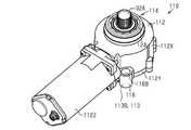
図13および図14に示されるとおり、自転車用コンポーネント110は、ハウジング112と、ハウジング112を自転車10に取り付けるための第1取付部114とを含む。自転車用コンポーネント110は、ハウジング112を自転車10のフレーム132に取り付けるための第2取付部116をさらに含む。ハウジング112は、自転車10のクランク軸32Aを支持する。ハウジング112は、クランク軸32Aを支持する支持部118を有する。ハウジング112は、モータ48の少なくとも一部を収容する。ハウジング112は、第1ハウジング112Xおよび第2ハウジング112Yを含む。第1ハウジング112Xは、クランク軸32Aの軸方向Cにおける第1側面部を含む。第2ハウジング112Yは、クランク軸32Aの軸方向Cにおいて、ハウジング112の第1側面部とは反対側の第2側面部を含む。第1ハウジング112Xと第2ハウジング112Yとは、ボルトBによって互いに取り付けられている。ハウジング112は、第3ハウジング112Zをさらに含む。第3ハウジング112Zは、クランク軸32Aの軸方向Cに垂直な方向において第1ハウジング112Xの外周部にボルトによって接続される。第3ハウジング112Zにモータ48が収容される。 As shown in FIGS. 13 and 14, thebicycle component 110 includes ahousing 112 and afirst attachment 114 for attaching thehousing 112 to thebicycle 10. Thebicycle component 110 further includes a second mountingportion 116 for mounting thehousing 112 to theframe 132 of thebicycle 10. Thehousing 112 supports thecrankshaft 32A of thebicycle 10. Thehousing 112 has asupport 118 that supports thecrankshaft 32A. Thehousing 112 houses at least a portion of themotor 48. Thehousing 112 includes afirst housing 112X and asecond housing 112Y. Thefirst housing 112X includes a first side surface portion in the axial direction C of thecrankshaft 32A. Thesecond housing 112Y includes a second side surface portion of thecrankshaft 32A in the axial direction C opposite to the first side surface portion of thehousing 112. Thefirst housing 112X and thesecond housing 112Y are attached to each other by bolts B. Thehousing 112 further includes athird housing 112Z. Thethird housing 112Z is connected to the outer peripheral portion of thefirst housing 112X by a bolt in a direction perpendicular to the axial direction C of thecrankshaft 32A. Themotor 48 is housed in thethird housing 112Z.

モータ48は、ハウジング112に設けられる。ハウジング112は、少なくとも一部がフレーム132に収容可能に構成される。自転車用コンポーネント110は、モータ48、減速機(図示略)、および、制御部(図示略)を含む。自転車用コンポーネント110のハウジング112は、第1実施形態の自転車用コンポーネント40と同様の部材を同様の配置で収容する。 Themotor 48 is provided in thehousing 112. Thehousing 112 is configured so that at least a part thereof can be accommodated in theframe 132. Thebicycle component 110 includes amotor 48, a speed reducer (not shown), and a control unit (not shown). Thehousing 112 of thebicycle component 110 houses the same members as thebicycle component 40 of the first embodiment in the same arrangement.

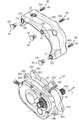
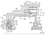
図15〜図17に示されるとおり、自転車用コンポーネント110の取付構造130は、第1取付部114と、フレーム132と、を含む。取付構造130は、第2取付部116をさらに含む。フレーム132は、フレーム本体134、および、フレーム本体134とは別体の取付部材136を含む。取付構造130は、取付部材136を、フレーム本体134に取り付けるためのボルト138をさらに含む。取付構造130は、第2取付部116をフレーム132に取り付けるための第1連結部材140をさらに含む。取付部材136は、いわゆるブラケットである。 As shown in FIGS. 15 to 17, the mountingstructure 130 of thebicycle component 110 includes a first mountingportion 114 and aframe 132. The mountingstructure 130 further includes a second mountingportion 116. Theframe 132 includes aframe body 134 and a mountingmember 136 that is separate from theframe body 134. The mountingstructure 130 further includesbolts 138 for mounting the mountingmember 136 to theframe body 134. The mountingstructure 130 further includes a first connectingmember 140 for mounting the second mountingportion 116 to theframe 132. The mountingmember 136 is a so-called bracket.

フレーム本体134は、図1に示すヘッドチューブ22A、トップチューブ22B、ダウンチューブ22C、シートチューブ22E、シートステイ22F、チェーンステイ22G、および、図15〜図17に示すコンポーネント取付部142を含む。図15〜図17は、シートチューブ22Eおよびチェーンステイ22Gを省略している。コンポーネント取付部142は、フレーム132のうちのダウンチューブ22Cの下端部、シートチューブ22Eの下端部、およびチェーンステイ22Gの前端部にそれぞれ接続されている。コンポーネント取付部142は、自転車用コンポーネント110の少なくとも一部を収容可能に構成されている。コンポーネント取付部142は、ダウンチューブ22C、シートチューブ22Eおよびチェーンステイ22Gと一体に形成されることが好ましいが、溶接、接着などによって接続されていてもよい。フレーム132には、自転車用コンポーネント110およびバッテリ18(図2参照)をフレーム132に収容するための第1開口部132Aが設けられる。第1開口部132Aは、コンポーネント取付部142、および、ダウンチューブ22Cのコンポーネント取付部22Dと接続される部分に設けられ、自転車10の下方に向かって開口する。コンポーネント取付部142は、自転車10の左右方向に配置される第1側壁部144および第2側壁部146と、自転車10の上方に配置される上壁部148とを含む。第1側壁部144および第2側壁部146は、ダウンチューブ22C、シートチューブ22Eおよびチェーンステイ22Gに連結される。第1側壁部144および第2側壁部146は、クランク軸32Aの軸方向から見た場合、実質的に円弧形状または扇形状に形成されていることが好ましい。第1側壁部144および第2側壁部146は、クランク軸32Aの軸方向から見た場合、第2側壁部146の開口は、第1側壁部144の開口よりも大きい。上壁部148は、第1側壁部144および第2側壁部146の上端部に連結され、ダウンチューブ22C、シートチューブ22E、および、チェーンステイ22Gに連結される。第1開口部132Aの開口は、コンポーネント取付部142の第1側壁部144および第2側壁部146のうちのクランク軸32Aが設けられる位置よりも自転車10の後方まで延びて形成されている。第1開口部132Aには、カバーが取り付けられることが好ましい。カバーは、第1開口部132Aの開口を閉塞する。カバーは、フレーム132に着脱可能に設けられてもよく、自転車用コンポーネント110に着脱可能に設けられてもよい。自転車用コンポーネント110は、第1開口部132Aの開口に下側から挿入されて、フレーム132に取り付けられる。 Theframe body 134 includes ahead tube 22A, atop tube 22B, adown tube 22C, aseat tube 22E, a seat stay 22F, achain stay 22G shown in FIG. 1, and acomponent mounting portion 142 shown in FIGS. 15 to 17. 15 to 17 omit theseat tube 22E and the chain stay 22G. Thecomponent mounting portion 142 is connected to the lower end portion of thedown tube 22C, the lower end portion of theseat tube 22E, and the front end portion of the chain stay 22G in theframe 132, respectively. Thecomponent mounting portion 142 is configured to accommodate at least a portion of thebicycle component 110. Thecomponent mounting portion 142 is preferably formed integrally with thedown tube 22C, theseat tube 22E, and the chain stay 22G, but may be connected by welding, adhesion, or the like. Theframe 132 is provided with afirst opening 132A for accommodating thebicycle component 110 and the battery 18 (see FIG. 2) in theframe 132. Thefirst opening 132A is provided at a portion connected to thecomponent mounting portion 142 and thecomponent mounting portion 22D of thedown tube 22C, and opens downward of thebicycle 10. Thecomponent mounting portion 142 includes a firstside wall portion 144 and a secondside wall portion 146 arranged in the left-right direction of thebicycle 10, and anupper wall portion 148 arranged above thebicycle 10. The firstside wall portion 144 and the secondside wall portion 146 are connected to thedown tube 22C, theseat tube 22E, and the chain stay 22G. The firstside wall portion 144 and the secondside wall portion 146 are preferably formed in a substantially arc shape or a fan shape when viewed from the axial direction of thecrankshaft 32A. When viewed from the axial direction of thecrankshaft 32A, the opening of the secondside wall portion 144 and the secondside wall portion 146 is larger than the opening of the firstside wall portion 144. Theupper wall portion 148 is connected to the upper end portions of the firstside wall portion 144 and the secondside wall portion 146, and is connected to thedown tube 22C, theseat tube 22E, and the chain stay 22G. The opening of thefirst opening 132A is formed so as to extend to the rear of thebicycle 10 from the position where thecrankshaft 32A is provided in the firstside wall portion 144 and the secondside wall portion 146 of thecomponent mounting portion 142. A cover is preferably attached to thefirst opening 132A. The cover closes the opening of thefirst opening 132A. The cover may be detachably provided on theframe 132 or may be detachably provided on thebicycle component 110. Thebicycle component 110 is inserted into the opening of thefirst opening 132A from below and attached to theframe 132.

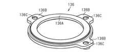
図15および図18に示されるとおり、取付部材136は、環状に形成される。取付部材136は、内周部136Aおよび外周部136Bを含む。内周部136Aは、円環状に形成される。外周部136Bは、内周部136Aから径方向の外方に突出する。外周部136Bは、複数設けられる。複数の外周部136Bは、周方向において不連続に設けられる。複数の外周部136Bは、周方向において連続するようにしてもよい。各外周部136Bは、雌ねじ部136Cを含む。本実施形態では、取付部材136には3つの外周部136Bが設けられる。各外周部136Bは、クランク軸32Aの回転軸心まわりに所定角度の間隔を開けて設けられる。所定角度は、30度以上かつ80度以下が好ましい。図17および図20に示されるとおり、取付部材136の外周部136Bは、フレーム本体134に取り付けられる。ボルト138は、フレーム本体134のうちのハウジング112とは反対側からフレーム本体134の孔144Aを貫通する。取付部材136は、ボルト138を介してフレーム本体134の第1側壁部144に取り付けられる。外周部136Bは、フレーム本体134とハウジング112の第1側壁部144との間に配置される。取付部材136の外周部136Bが第1側壁部144のうちのハウジング112側の面に配置された状態で、ボルト138がハウジング112とは反対側から第1側壁部144の孔144Aを通過して雌ねじ部136Cに結合される。クランク軸32Aの軸方向Cにおいて、取付部材136の外周部136Bは、内周部136Aからオフセットして設けられることが好ましい。取付部材136の内周部136Aの少なくとも一部は、クランク軸32Aの軸方向Cにおいて、第1側壁部144と重なる位置に設けられることが好ましい。ボルト138のボルトヘッドと、外周部136Bとの間に、第1側壁部144が挟まれる。第1側壁部144の孔144Aをねじ孔に変更し、外周部136Bの雌ねじ部136Cを貫通孔に変更して、ボルト138のボルトヘッドと、第1側壁部144との間に、外周部136Bを挟む構成としてもよい。この場合、取付部材136の外周部136Bは、第1側壁部144のうちのハウジング112側の面に配置されてもよく、第1側壁部144のうちのハウジング112とは反対側の面に配置されてもよい。 As shown in FIGS. 15 and 18, the mountingmember 136 is formed in an annular shape. The mountingmember 136 includes an innerperipheral portion 136A and an outerperipheral portion 136B. The innerperipheral portion 136A is formed in an annular shape. The outerperipheral portion 136B protrudes outward in the radial direction from the innerperipheral portion 136A. A plurality of outerperipheral portions 136B are provided. The plurality of outerperipheral portions 136B are provided discontinuously in the circumferential direction. The plurality of outerperipheral portions 136B may be continuous in the circumferential direction. Each outerperipheral portion 136B includes afemale screw portion 136C. In the present embodiment, the mountingmember 136 is provided with three outerperipheral portions 136B. Each outerperipheral portion 136B is provided around the center of rotation of thecrankshaft 32A at a predetermined angle. The predetermined angle is preferably 30 degrees or more and 80 degrees or less. As shown in FIGS. 17 and 20, the outerperipheral portion 136B of the mountingmember 136 is mounted on theframe body 134. Thebolt 138 penetrates thehole 144A of theframe body 134 from the side of theframe body 134 opposite to thehousing 112. The mountingmember 136 is mounted on the firstside wall portion 144 of the framemain body 134 via thebolt 138. The outerperipheral portion 136B is arranged between the framemain body 134 and the firstside wall portion 144 of thehousing 112. With the outerperipheral portion 136B of the mountingmember 136 arranged on the surface of the firstside wall portion 144 on thehousing 112 side, thebolt 138 passes through thehole 144A of the firstside wall portion 144 from the side opposite to thehousing 112. It is coupled to thefemale screw portion 136C. In the axial direction C of thecrankshaft 32A, the outerperipheral portion 136B of the mountingmember 136 is preferably provided offset from the innerperipheral portion 136A. It is preferable that at least a part of the innerperipheral portion 136A of the mountingmember 136 is provided at a position overlapping the firstside wall portion 144 in the axial direction C of thecrankshaft 32A. The firstside wall portion 144 is sandwiched between the bolt head of thebolt 138 and the outerperipheral portion 136B. Thehole 144A of the firstside wall portion 144 is changed to a screw hole, thefemale screw portion 136C of the outerperipheral portion 136B is changed to a through hole, and the outerperipheral portion 136B is provided between the bolt head of thebolt 138 and the firstside wall portion 144. It may be configured to sandwich. In this case, the outerperipheral portion 136B of the mountingmember 136 may be arranged on the surface of the firstside wall portion 144 on the side opposite to thehousing 112, and may be arranged on the surface of the firstside wall portion 144 opposite to thehousing 112. May be done.

図19および図20に示されるとおり、第1取付部114は、第1部分120と、第2部分122と、を含む。第1取付部114は、支持部118から独立してハウジング112に設けられる。第1取付部114と第2取付部116とは、所定方向において相互に離間して設けられる。所定方向は、クランク軸32Aの軸方向Cに平行する。第1取付部114は、第1ハウジング112Xに設けられる。第2取付部116は、第1ハウジング112Xに設けられる。第2取付部116は、第2ハウジング112Yに設けられてもよい。 As shown in FIGS. 19 and 20, the first mountingportion 114 includes afirst portion 120 and asecond portion 122. The first mountingportion 114 is provided on thehousing 112 independently of the supportingportion 118. The first mountingportion 114 and the second mountingportion 116 are provided so as to be separated from each other in a predetermined direction. The predetermined direction is parallel to the axial direction C of thecrankshaft 32A. The first mountingportion 114 is provided in thefirst housing 112X. Thesecond mounting portion 116 is provided in thefirst housing 112X. Thesecond mounting portion 116 may be provided in thesecond housing 112Y.

第1部分120は、ハウジング112に結合される。第1取付部114は、環状部材124を含む。環状部材124は、円環状に形成される。環状部材124は、第1実施形態の第1部材68と同様の構造を有する。環状部材124は、内周部124Aおよび外周部124Bを含む。第1部分120は、内周部124Aに設けられる。第2部分122は、外周部124Bに設けられる。第2部分122は、ハウジング112から離反する方向にフレーム132を押圧するように構成される。具体的には、第2部分122は、取付部材136をハウジング112から離反する方向に押圧する。環状部材124は、第1方向に延びる第1孔124Hを含む。第1孔124Hは、クランク軸32Aが貫通する貫通孔を含む。第1方向は、クランク軸32Aの軸方向Cと一致する。環状部材124は、第1方向およびクランク軸32Aの軸方向Cに交差する方向において、ハウジング112に支持されるように構成される。環状部材124の第1孔124Hには、ハウジング112の一部が挿入される。ハウジング112は、環状部材124の第1孔124Hに挿入される挿入部分112Bを含む。挿入部分112Bは、支持部118に含まれることが好ましい。環状部材124は、内周部124Aがハウジング112の挿入部分112Bに支持される。 Thefirst portion 120 is coupled to thehousing 112. The first mountingportion 114 includes anannular member 124. Theannular member 124 is formed in an annular shape. Theannular member 124 has a structure similar to that of thefirst member 68 of the first embodiment. Theannular member 124 includes an innerperipheral portion 124A and an outerperipheral portion 124B. Thefirst portion 120 is provided on the innerperipheral portion 124A. Thesecond portion 122 is provided on the outerperipheral portion 124B. Thesecond portion 122 is configured to press theframe 132 in a direction away from thehousing 112. Specifically, thesecond portion 122 presses the mountingmember 136 in a direction away from thehousing 112. Theannular member 124 includes afirst hole 124H extending in the first direction. Thefirst hole 124H includes a through hole through which thecrankshaft 32A penetrates. The first direction coincides with the axial direction C of thecrankshaft 32A. Theannular member 124 is configured to be supported by thehousing 112 in a first direction and in a direction intersecting the axial direction C of thecrankshaft 32A. A part of thehousing 112 is inserted into thefirst hole 124H of theannular member 124. Thehousing 112 includes aninsertion portion 112B that is inserted into thefirst hole 124H of theannular member 124. Theinsertion portion 112B is preferably included in thesupport portion 118. The innerperipheral portion 124A of theannular member 124 is supported by theinsertion portion 112B of thehousing 112.

環状部材124は、ハウジング112を押圧するように構成される。具体的には、環状部材124は、内周部124Aがハウジング112を押圧するように構成される。環状部材124は、外周部124Bの第1方向の第1端面124Cが内周部124Aがハウジング112を押圧する方向とは反対方向に、フレーム132の取付部材136を押圧するように構成される。 Theannular member 124 is configured to press thehousing 112. Specifically, theannular member 124 is configured such that the innerperipheral portion 124A presses thehousing 112. Theannular member 124 is configured such that thefirst end surface 124C of the outerperipheral portion 124B in the first direction presses the mountingmember 136 of theframe 132 in the direction opposite to the direction in which the innerperipheral portion 124A presses thehousing 112.

ハウジング112は、第1ねじ部112Aを有する。ハウジング112の第1ねじ部112Aは、クランク軸32Aの回転軸心まわりにおいてクランク軸32Aの外周面を囲むように形成される。挿入部分112Bは、ハウジング112のうちのクランク軸32Aの軸方向Cの一端部が突出する部分を含む。挿入部分112Bは、環状に形成されている。クランク軸32Aの軸方向Cに垂直な方向における挿入部分112Bの内径は、クランク軸32Aの軸方向Cに垂直な方向におけるクランク軸32Aの外径よりも大きい。挿入部分112Bの内周部は、クランク軸32Aから離間する。挿入部分112Bに、第1ねじ部112Aが設けられる。第1ねじ部112Aは、クランク軸32Aの軸方向Cに垂直な方向において、挿入部分112Bの外周部に設けられる。第1取付部114の第1部分120は、第1ねじ部112Aに結合される第2ねじ部120Aを有する。第2ねじ部120Aには、雌ねじが設けられる。ハウジング112の第1ねじ部112Aには、第2ねじ部120Aの雌ねじに結合される雄ねじが設けられる。 Thehousing 112 has a first threadedportion 112A. Thefirst screw portion 112A of thehousing 112 is formed so as to surround the outer peripheral surface of thecrankshaft 32A around the center of rotation of thecrankshaft 32A. Theinsertion portion 112B includes a portion of thehousing 112 in which one end of thecrankshaft 32A in the axial direction C protrudes. Theinsertion portion 112B is formed in an annular shape. The inner diameter of theinsertion portion 112B in the direction perpendicular to the axial direction C of thecrankshaft 32A is larger than the outer diameter of thecrankshaft 32A in the direction perpendicular to the axial direction C of thecrankshaft 32A. The inner peripheral portion of theinsertion portion 112B is separated from thecrankshaft 32A. Theinsertion portion 112B is provided with afirst screw portion 112A. Thefirst screw portion 112A is provided on the outer peripheral portion of theinsertion portion 112B in a direction perpendicular to the axial direction C of thecrankshaft 32A. Thefirst portion 120 of the first mountingportion 114 has a second threadedportion 120A coupled to the first threadedportion 112A. A female screw is provided on thesecond screw portion 120A. The first threadedportion 112A of thehousing 112 is provided with a male thread that is coupled to the female thread of the second threadedportion 120A.

第1取付部114の第2部分122は、第2ねじ部120Aが第1ねじ部112Aに結合して移動する第1方向と交差する第2方向に延びる。第1方向は、クランク軸32Aの軸方向に平行な方向である。取付部材136の内周部136Aは、第1取付部114に接触する。 Thesecond portion 122 of the first mountingportion 114 extends in a second direction that intersects the first direction in which the second threadedportion 120A is coupled to and moves from the first threadedportion 112A. The first direction is a direction parallel to the axial direction of thecrankshaft 32A. The innerperipheral portion 136A of the mountingmember 136 comes into contact with the first mountingportion 114.

図15に示されるとおり、第1取付部114は、工具を係合可能な工具係合部126をさらに含む。工具係合部126は、環状部材124の内周部124Aまたは外周部124Bの少なくとも一方に形成されることが好ましい。本実施形態では、工具係合部126は、環状部材124の内周部124Aに形成される。工具係合部126は、クランク軸32Aに関して径方向に突出する凸部および凹む凹部を含む。凸部および凹部は、クランク軸32Aまわりの周方向において所定の間隔をあけて、交互に配置されることが好ましい。 As shown in FIG. 15, the first mountingportion 114 further includes atool engaging portion 126 capable of engaging the tool. Thetool engaging portion 126 is preferably formed on at least one of the innerperipheral portion 124A and the outerperipheral portion 124B of theannular member 124. In the present embodiment, thetool engaging portion 126 is formed on the innerperipheral portion 124A of theannular member 124. Thetool engaging portion 126 includes a convex portion and a concave concave portion that project radially with respect to thecrankshaft 32A. It is preferable that the convex portions and the concave portions are alternately arranged at predetermined intervals in the circumferential direction around thecrankshaft 32A.

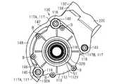
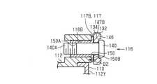
第2取付部116は、ハウジング112に形成される第1貫通孔116Aおよび第2貫通孔116Bと、第1連結部材140とを含む。第2取付部116は、第1ハウジング112Xのクランク軸32Aのまわりの外周部から突出する複数の凸部113を含む。複数の凸部113は、第1貫通孔116Aが形成される第1凸部113Aと、第2貫通孔116Bが形成される第2凸部113Bとを含む。第1凸部113Aは、複数設けられることが好ましい。第1貫通孔116Aおよび第2貫通孔116Bは、第1方向に延びる。第2貫通孔116Bの内径は、第1貫通孔116Aの内径よりも大きいことが好ましい。本実施形態では、第1凸部113Aが2つ設けられ、第2凸部113Bが1つ設けられている。クランク軸32Aの軸方向Cから見て、クランク軸32Aまわりに相互に隣り合う第1貫通孔116Aの中心および第2貫通孔116Bの中心を結ぶ直線と、第1貫通孔116Aの中心および第1貫通孔116Aの中心とを結ぶ直線とに囲まれる第1範囲に、クランク軸32Aの回転軸心が配置されることが好ましい。好ましくは、第1範囲に、クランク軸32Aが配置される。第1貫通孔116Aは3つ以上形成されていてもよく、第2貫通孔116Bは2つ以上形成されていてもよい。第1貫通孔116Aの1つは、クランク軸32Aの軸方向から見て、モータ48との間にクランク軸32Aを挟む位置に設けられることが好ましい。第1貫通孔116Aの他の1つと、第2貫通孔116Bとは、第1ハウジング112Xと第3ハウジング112Zとが接続されている位置に設けられることが好ましい。第1貫通孔116Aの他の1つと、第2貫通孔116Bとは、クランク軸32Aの軸方向から見て、前記クランク軸32Aまわりの第3ハウジング112Zの幅方向の両端部にそれぞれ設けられることが好ましい。第1貫通孔116Aおよび第2貫通孔116Bは、第1ハウジング112Xには、第1凸部113Aおよび第2凸部113Bが形成されず、第1ハウジング112Xの外周部に第1貫通孔116Aおよび第2貫通孔116Bが設けられてもよい。第1ハウジング112Xには、第1凸部113Aおよび第2凸部113Bの両方ではなく、第1凸部113Aのみが設けられてもよい。この場合ハウジング112には、第1貫通孔116Aのみが設けられ、第2貫通孔116Bの筒状部材150とボルトが接続される構造は、第1貫通孔116Aに挿入されるボルトが第2側壁部146のねじ部146Aと接続される構造に置き替えられる。 Thesecond mounting portion 116 includes a first throughhole 116A and a second throughhole 116B formed in thehousing 112, and a first connectingmember 140. Thesecond mounting portion 116 includes a plurality ofconvex portions 113 protruding from the outer peripheral portion around thecrankshaft 32A of thefirst housing 112X. The plurality ofconvex portions 113 include a firstconvex portion 113A in which the first throughhole 116A is formed and a secondconvex portion 113B in which the second throughhole 116B is formed. It is preferable that a plurality of firstconvex portions 113A are provided. The first throughhole 116A and the second throughhole 116B extend in the first direction. The inner diameter of the second throughhole 116B is preferably larger than the inner diameter of the first throughhole 116A. In the present embodiment, two firstconvex portions 113A are provided and one secondconvex portion 113B is provided. A straight line connecting the centers of the first throughholes 116A and the centers of the second throughholes 116B adjacent to each other around thecrankshaft 32A, the center of the first throughholes 116A, and the first throughhole 116A when viewed from the axial direction C of thecrankshaft 32A. It is preferable that the rotation axis of thecrankshaft 32A is arranged in the first range surrounded by the straight line connecting the center of the throughhole 116A. Preferably, thecrankshaft 32A is arranged in the first range. Three or more first throughholes 116A may be formed, and two or more second throughholes 116B may be formed. It is preferable that one of the first throughholes 116A is provided at a position where thecrankshaft 32A is sandwiched between thecrankshaft 32A and themotor 48 when viewed from the axial direction of thecrankshaft 32A. The other one of the first throughhole 116A and the second throughhole 116B are preferably provided at a position where thefirst housing 112X and thethird housing 112Z are connected. The other one of the first throughhole 116A and the second throughhole 116B are provided at both ends in the width direction of thethird housing 112Z around thecrankshaft 32A when viewed from the axial direction of thecrankshaft 32A. Is preferable. In the first throughhole 116A and the second throughhole 116B, the firstconvex portion 113A and the secondconvex portion 113B are not formed in thefirst housing 112X, and the first throughhole 116A and the first throughhole 116A and the outer peripheral portion of thefirst housing 112X are formed. A second throughhole 116B may be provided. Thefirst housing 112X may be provided with only the firstconvex portion 113A, not both the firstconvex portion 113A and the secondconvex portion 113B. In this case, thehousing 112 is provided with only the first throughhole 116A, and the structure in which thetubular member 150 of the second throughhole 116B and the bolt are connected is such that the bolt inserted into the first throughhole 116A is the second side wall. It is replaced with a structure connected to the threadedportion 146A of theportion 146.

第2取付部116は、複数の取付面117を有する。複数の取付面117は、第1の取付面117A、第2の取付面117Bを含む。第1の取付面117Aには、第1貫通孔116Aが開口する。第2の取付面117Bには、第2貫通孔116Bが開口する。第1の取付面117Aは、第1凸部113Aに形成される。第2の取付面117Bは、第2凸部113Bに形成される。第1の取付面117A、第2の取付面117Bは、クランク軸32Aの回転軸に垂直な方向に延びる。第1の取付面117Aおよび第2の取付面117Bは、クランク軸32Aの軸方向Cにオフセットして配置される。第1の取付面117Aは、第2の取付面117Bよりも、クランク軸32Aの軸方向Cにおいて、第1取付部114寄りに配置されることが好ましい。第2側壁部146は、第1の取付面117Aに対応する第1フレーム取付部147Aと、第2の取付面117Bに対応する第2フレーム取付部147Bとを含む。第1フレーム取付部147Aと、第2フレーム取付部147Bとは、クランク軸32Aの軸方向Cにオフセットして配置される。第1フレーム取付部147Aは、第2フレーム取付部147Bよりもクランク軸32Aの軸方向Cにおいて、第1取付部114寄りに配置されることが好ましい。第1貫通孔116Aおよび第2貫通孔116Bは、クランク軸32Aの軸方向Cから見て、クランク軸32Aの回転軸心と後輪30の回転軸心とを結ぶ線分に重ならないように設けられることが好ましい。第1貫通孔116Aおよび第2貫通孔116Bは、好ましくは、シートチューブ22Eおよび上壁部148の接続部と、チェーンステイ22Gおよび上壁部148の接続部とからオフセットして配置されていてもよい。 Thesecond mounting portion 116 has a plurality of mountingsurfaces 117. The plurality of mountingsurfaces 117 include a first mountingsurface 117A and asecond mounting surface 117B. A first throughhole 116A opens in the first mountingsurface 117A. A second throughhole 116B opens in the second mountingsurface 117B. Thefirst mounting surface 117A is formed on the firstconvex portion 113A. Thesecond mounting surface 117B is formed on the secondconvex portion 113B. Thefirst mounting surface 117A and the second mountingsurface 117B extend in a direction perpendicular to the rotation axis of thecrankshaft 32A. Thefirst mounting surface 117A and the second mountingsurface 117B are arranged so as to be offset in the axial direction C of thecrankshaft 32A. Thefirst mounting surface 117A is preferably arranged closer to the first mountingportion 114 in the axial direction C of thecrankshaft 32A than the second mountingsurface 117B. The secondside wall portion 146 includes a firstframe mounting portion 147A corresponding to the first mountingsurface 117A and a secondframe mounting portion 147B corresponding to the second mountingsurface 117B. The firstframe mounting portion 147A and the secondframe mounting portion 147B are arranged so as to be offset in the axial direction C of thecrankshaft 32A. The firstframe mounting portion 147A is preferably arranged closer to the first mountingportion 114 in the axial direction C of thecrankshaft 32A than the secondframe mounting portion 147B. The first throughhole 116A and the second throughhole 116B are provided so as not to overlap the line connecting the rotation axis of thecrankshaft 32A and the rotation axis of the rear wheel 30 when viewed from the axial direction C of thecrankshaft 32A. Is preferable. The first throughhole 116A and the second throughhole 116B are preferably arranged offset from the connection portion of theseat tube 22E and theupper wall portion 148 and the connection portion of the chain stay 22G and theupper wall portion 148. good.

図21に示されるとおり、第2貫通孔116Bには、筒状部材150が配置される。筒状部材150、第2凸部113Bの第2貫通孔116Bに圧入されることが好ましい。筒状部材150は、軸方向の一端部にフランジ部150Bを有する。フランジ部150Bの外径は、第2貫通孔116Bの内径よりも大きくなるように形成されている。フランジ部150Bは、第2凸部113Bとフレーム本体134との間に配置される。筒状部材150は、第2貫通孔116Bにおいて、第2貫通孔116Bの延びる方向の位置を調整できるように構成される。筒状部材150の内周部150Aには、雌ねじ部が形成される。 As shown in FIG. 21, atubular member 150 is arranged in the second throughhole 116B. It is preferable that thetubular member 150 is press-fitted into the second throughhole 116B of the secondconvex portion 113B. Thetubular member 150 has aflange portion 150B at one end in the axial direction. The outer diameter of theflange portion 150B is formed to be larger than the inner diameter of the second throughhole 116B. Theflange portion 150B is arranged between the secondconvex portion 113B and the framemain body 134. Thetubular member 150 is configured so that the position of the second throughhole 116B in the extending direction can be adjusted in the second throughhole 116B. A female screw portion is formed on the innerperipheral portion 150A of thetubular member 150.

図19および図21に示されるとおり、第1連結部材140は、雄ねじ140Aを含む。第1連結部材140は、第1貫通孔116Aおよび第2貫通孔116Bのそれぞれに挿入される。第1貫通孔116Aに挿入される第1連結部材140は、第1貫通孔116Aを貫通して第2側壁部146のねじ部146Aに連結される。フレーム132には、第1貫通孔116Aに対応する位置に、第1連結部材140を挿入可能なねじ部146Aが形成されている。ねじ部146Aには、雌ねじが形成されている。第1連結部材140は、ボルトを含む。第1貫通孔116Aに挿入される第1連結部材140のボルトヘッドと、フレーム132の第2側壁部146との間に、ハウジング112が挟み込まれる。 As shown in FIGS. 19 and 21, the first connectingmember 140 includes amale screw 140A. The first connectingmember 140 is inserted into each of the first throughhole 116A and the second throughhole 116B. The first connectingmember 140 inserted into the first throughhole 116A penetrates the first throughhole 116A and is connected to the threadedportion 146A of the secondside wall portion 146. Theframe 132 is formed with ascrew portion 146A into which the first connectingmember 140 can be inserted at a position corresponding to the first throughhole 116A. A female thread is formed in the threadedportion 146A. The first connectingmember 140 includes a bolt. Thehousing 112 is sandwiched between the bolt head of the first connectingmember 140 inserted into the first throughhole 116A and the secondside wall portion 146 of theframe 132.

第2貫通孔116Bに挿入される第1連結部材140は、筒状部材150の内周部150Aの雌ねじ部に連結される。第2貫通孔116Bに挿入される第1連結部材140のボルトヘッドと、ハウジング112との間に、フレーム132の第2側壁部146が挟み込まれる。フレーム132には、第2貫通孔116Bに対応する位置に、第1連結部材140を挿入可能な貫通孔が形成されている。自転車用コンポーネント110をフレーム132に取り付ける場合、第1連結部材140を、第1貫通孔116Aに挿入して、第2側壁部146のねじ部146Aに連結して、フレーム132とハウジング112とを固定する。その後、他の第1連結部材140を、フレーム132の貫通孔に挿入して第2貫通孔116Bに連結する。筒状部材150のフランジ部とフレーム132との間に隙間がある場合、第1連結部材140を接続することによって、筒状部材150がフレーム132に近づく方向に移動させて、フランジ部150Bとフレーム132とを接触させることができる。 The first connectingmember 140 inserted into the second throughhole 116B is connected to the female threaded portion of the innerperipheral portion 150A of thetubular member 150. The secondside wall portion 146 of theframe 132 is sandwiched between the bolt head of the first connectingmember 140 inserted into the second throughhole 116B and thehousing 112. Theframe 132 is formed with a through hole into which the first connectingmember 140 can be inserted at a position corresponding to the second throughhole 116B. When attaching thebicycle component 110 to theframe 132, the first connectingmember 140 is inserted into the first throughhole 116A and connected to the threadedportion 146A of the secondside wall portion 146 to fix theframe 132 and thehousing 112. do. After that, another first connectingmember 140 is inserted into the through hole of theframe 132 and connected to the second throughhole 116B. When there is a gap between the flange portion of thetubular member 150 and theframe 132, by connecting the first connectingmember 140, thetubular member 150 is moved in the direction closer to theframe 132, and theflange portion 150B and the frame are moved. It can be brought into contact with 132.

図19および図20に示されるとおり、第1取付部114は、ハウジング112とフレーム132とが相互に離反する方向の力を、ハウジング112とフレーム132と付与するように構成される。第1取付部114は、クランク軸32Aの軸方向Cにおいて、ハウジング112とフレーム132とが相互に離反する方向の力を、ハウジング112とフレーム132とに付与するように構成される。具体的には、第1部分120は、第2ねじ部120Aが第1ねじ部112Aにねじ込まれることによって、環状部材124の軸力によってハウジング112に第2取付部116側に向かう方向A1の力を付与する。第2部分122は、環状部材124の端面124Cによってフレーム132に方向A1とは反対の方向A2に向かう力を付与する。 As shown in FIGS. 19 and 20, the first mountingportion 114 is configured to apply a force in a direction in which thehousing 112 and theframe 132 are separated from each other to thehousing 112 and theframe 132. The first mountingportion 114 is configured to apply a force in the axial direction C of thecrankshaft 32A in a direction in which thehousing 112 and theframe 132 are separated from each other to thehousing 112 and theframe 132. Specifically, in thefirst portion 120, when thesecond screw portion 120A is screwed into thefirst screw portion 112A, the axial force of theannular member 124 causes a force in the direction A1 toward the second mountingportion 116 side on thehousing 112. Is given. Thesecond portion 122 applies a force to theframe 132 in the direction A2 opposite to the direction A1 by theend surface 124C of theannular member 124.

図19および図21に示されるとおり、第2取付部116は、ハウジング112とフレーム132とが相互に近付く方向の力を、ハウジング112とフレーム132とに付与するように構成される。第2取付部116は、クランク軸32Aの軸方向Cにおいて、ハウジング112とフレーム132とが相互に近付く方向の力を、ハウジング112とフレーム132とに付与するように構成される。具体的には、第2貫通孔116Bに挿入される第1連結部材140は、第1連結部材140の軸力によってハウジング112にフレーム132の第2側壁部146のうちの第1側壁部144側の面に向かう方向B1の力を付与する。第1貫通孔116Aに配置される第1連結部材140は、第1連結部材140の軸力によってハウジング112にフレーム132の第2側壁部146から第1側壁部144に向かう方向B2の力を付与する。方向B1および方向B2は、相互に離反する方向である。 As shown in FIGS. 19 and 21, the second mountingportion 116 is configured to apply a force to thehousing 112 and theframe 132 in a direction in which thehousing 112 and theframe 132 approach each other. Thesecond mounting portion 116 is configured to apply a force in the axial direction C of thecrankshaft 32A in a direction in which thehousing 112 and theframe 132 approach each other to thehousing 112 and theframe 132. Specifically, the first connectingmember 140 inserted into the second throughhole 116B is located on thehousing 112 on the firstside wall portion 144 side of the secondside wall portion 146 of theframe 132 due to the axial force of the first connectingmember 140. Apply the force in the direction B1 toward the surface of. The first connectingmember 140 arranged in the first throughhole 116A applies a force in the direction B2 from the secondside wall portion 146 of theframe 132 toward the firstside wall portion 144 to thehousing 112 by the axial force of the first connectingmember 140. do. Direction B1 and direction B2 are directions that are separated from each other.

自転車用コンポーネント110のフレーム132への取り付け方法について説明する。自転車用コンポーネント110のフレーム132への取り付け方法は、第1工程、第2工程、第3工程、および、第4工程を含む。 A method of attaching thebicycle component 110 to theframe 132 will be described. The method of attaching thebicycle component 110 to theframe 132 includes a first step, a second step, a third step, and a fourth step.

第1工程では、作業者は、ハウジング112に第1取付部114を取り付け、取付部材136を第1取付部114に支持させた状態で、フレーム132の第1開口部132Aからコンポーネント取付部142の収容空間に、自転車用コンポーネント110を下方から挿入する。 In the first step, the operator attaches thefirst attachment portion 114 to thehousing 112, and with theattachment member 136 supported by thefirst attachment portion 114, from thefirst opening 132A of theframe 132 to thecomponent attachment portion 142. Thebicycle component 110 is inserted into the accommodation space from below.

第2工程では、作業者は、第2取付部116によってハウジング112をフレーム132に取り付ける。
第3工程では、作業者は、取付部材136をフレーム本体134にボルト138によって固定する。
In the second step, the operator attaches thehousing 112 to theframe 132 by thesecond attachment portion 116.
In the third step, the operator fixes the mountingmember 136 to theframe body 134 withbolts 138.

第4工程では、作業者は、第1取付部114の工具係合部126に工具を係合させ、第1取付部114の第2ねじ部120Aが第1ねじ部112Aから外れる方向に第1取付部114を回転させて、第1取付部114の環状部材124の端面124Cによってフレーム132を押圧する。第3工程は、第1工程の前に行ってもよい。 In the fourth step, the operator engages the tool with thetool engaging portion 126 of the first mountingportion 114, and thefirst screw portion 120A of the first mountingportion 114 is disengaged from thefirst screw portion 112A. The mountingportion 114 is rotated to press theframe 132 by theend surface 124C of theannular member 124 of the first mountingportion 114. The third step may be performed before the first step.

(第5実施形態)
図22〜図24を参照して、第5実施形態の自転車用コンポーネント110および自転車用コンポーネント110の取付構造160について説明する。第4実施形態の自転車用コンポーネント110は、第2取付部164の構成および取付構造160が異なる点以外は第4実施形態の自転車用コンポーネント110と同様であるので、第4実施形態と共通する構成については、第4実施形態と同一の符号を付し、重複する説明を省略する。
(Fifth Embodiment)
Thebicycle component 110 and the mountingstructure 160 of thebicycle component 110 of the fifth embodiment will be described with reference to FIGS. 22 to 24. Thebicycle component 110 of the fourth embodiment is the same as thebicycle component 110 of the fourth embodiment except that the configuration of the second mountingportion 164 and the mountingstructure 160 are different. With the same reference numerals as those of the fourth embodiment, duplicate description will be omitted.

図22〜図24に示されるとおり、自転車用コンポーネント110は、ハウジング112と、ハウジング112を自転車10に取り付けるための第1取付部114とを含む。自転車用コンポーネント110は、ハウジング112を自転車10のフレーム132に取り付けるための第2取付部164をさらに含む。 As shown in FIGS. 22-24, thebicycle component 110 includes ahousing 112 and afirst attachment 114 for attaching thehousing 112 to thebicycle 10. Thebicycle component 110 further includes a second mountingportion 164 for mounting thehousing 112 to theframe 132 of thebicycle 10.

自転車用コンポーネント110の取付構造160は、第1取付部114と、フレーム132と、を含む。取付構造160は、第2取付部164をさらに含む。フレーム132は、フレーム本体134、および、フレーム本体134とは別体の取付部材166を含む。取付構造160は、取付部材166を、フレーム本体134に取り付けるためのボルト168をさらに含む。取付構造160は、ボルト168に結合されるナット170をさらに含む。図22では、シートチューブ22Eおよびチェーンステイ22Gを省略している。 The mountingstructure 160 of thebicycle component 110 includes a first mountingportion 114 and aframe 132. The mountingstructure 160 further includes a second mountingportion 164. Theframe 132 includes aframe body 134 and a mountingmember 166 that is separate from theframe body 134. The mountingstructure 160 further includesbolts 168 for mounting the mountingmember 166 to theframe body 134. The mountingstructure 160 further includes anut 170 that is coupled to thebolt 168. In FIG. 22, theseat tube 22E and the chain stay 22G are omitted.

取付部材166は、環状に形成される。取付部材166は、内周部166Aおよび外周部166Bを含む。内周部166Aは、円環状に形成される。取付部材166の内周部166Aは、取付部材136の内周部と同様な形状を有する。外周部166Bは、内周部166Aから径方向の外方に突出する。外周部166Bは、複数設けられる。複数の外周部166Bは、周方向において不連続に設けられる。複数の外周部166Bは、周方向において連続するようにしてもよい。各外周部166Bは、貫通孔166Cを含む。取付部材166の外周部166Bは、フレーム本体134に取り付けられる。 The mountingmember 166 is formed in an annular shape. The mountingmember 166 includes an innerperipheral portion 166A and an outerperipheral portion 166B. The innerperipheral portion 166A is formed in an annular shape. The innerperipheral portion 166A of the mountingmember 166 has the same shape as the inner peripheral portion of the mountingmember 136. The outerperipheral portion 166B protrudes outward in the radial direction from the innerperipheral portion 166A. A plurality of outerperipheral portions 166B are provided. The plurality of outerperipheral portions 166B are provided discontinuously in the circumferential direction. The plurality of outerperipheral portions 166B may be continuous in the circumferential direction. Each outerperipheral portion 166B includes a throughhole 166C. The outerperipheral portion 166B of the mountingmember 166 is mounted on the framemain body 134.

第2取付部164は、ハウジング112に形成される第1貫通孔116A、第2貫通孔116B、ボルト168、および、ナット170を含む。第2貫通孔116Bには、筒状部材150が配置される。第1貫通孔116Aおよび第2貫通孔116Bには、それぞれボルト168が挿入される。筒状部材150の内周部150Aの雌ねじ部は、ボルト168に結合される。 Thesecond mounting portion 164 includes a first throughhole 116A, a second throughhole 116B, abolt 168, and anut 170 formed in thehousing 112. Atubular member 150 is arranged in the second throughhole 116B.Bolts 168 are inserted into the first throughhole 116A and the second throughhole 116B, respectively. The female threaded portion of the innerperipheral portion 150A of thetubular member 150 is coupled to thebolt 168.

第2取付部164は、ボルト168およびナット170によってハウジング112をフレーム132に取り付けるとともに、フレーム本体134に取付部材166を取り付ける機能を有する。 Thesecond mounting portion 164 has a function of mounting thehousing 112 to theframe 132 bybolts 168 andnuts 170, and mounting the mountingmember 166 to the framemain body 134.

フレーム本体134には、クランク軸32Aの軸方向Cにフレーム本体134を貫通する第1フレーム貫通孔134Aおよび第2フレーム貫通孔134Bが形成されている。図23に示されるとおり、自転車用コンポーネント110をフレーム本体134に取り付けた状態において、第1貫通孔116Aは、第1フレーム貫通孔134Aと繋がる位置に配置されている。第1フレーム貫通孔134Aは、フレーム本体134のうちの第1側壁部144と第2側壁部146とが上壁部148によって接続される部分に形成され、第1側壁部144、上壁部148、および、第2側壁部146を第1方向に貫通する。第1貫通孔116Aに挿入されるボルト168は、第2側壁部146側から第1貫通孔116A、第1フレーム貫通孔134A、および、取付部材166の貫通孔166Cを貫通し、取付部材166のうちのフレーム本体134とは反対側からボルト168の先端の雄ねじにナット170が結合される。第1貫通孔116Aに配置されるボルト168は、取付部材166側から、取付部材166の貫通孔166C、第1フレーム貫通孔134A、および、第1貫通孔116Aを貫通し、第2ハウジング112Y側からボルト168の先端部168Aの雄ねじにナット170が結合されてもよい。第1貫通孔116Aに配置されるボルト168とナット170とは、ボルトヘッドとナット170との間に、ハウジング112、フレーム本体134、および、取付部材166を挟み込む。 Theframe body 134 is formed with a first frame throughhole 134A and a second frame throughhole 134B that penetrate theframe body 134 in the axial direction C of thecrankshaft 32A. As shown in FIG. 23, in a state where thebicycle component 110 is attached to the framemain body 134, the first throughhole 116A is arranged at a position connected to the first frame throughhole 134A. The first frame throughhole 134A is formed in a portion of the framemain body 134 in which the firstside wall portion 144 and the secondside wall portion 146 are connected by theupper wall portion 148, and the firstside wall portion 144 and theupper wall portion 148 are formed. , And penetrate the secondside wall portion 146 in the first direction. Thebolt 168 inserted into the first throughhole 116A penetrates the first throughhole 116A, the first frame throughhole 134A, and the throughhole 166C of the mountingmember 166 from the secondside wall portion 146 side, and the mountingmember 166 Thenut 170 is connected to the male screw at the tip of thebolt 168 from the side opposite to the framemain body 134. Thebolt 168 arranged in the first throughhole 116A penetrates the throughhole 166C of the mountingmember 166, the first frame throughhole 134A, and the first throughhole 116A from the mountingmember 166 side, and penetrates thesecond housing 112Y side. Thenut 170 may be coupled to the male screw of thetip portion 168A of thebolt 168. Thebolt 168 and thenut 170 arranged in the first throughhole 116A sandwich thehousing 112, the framemain body 134, and the mountingmember 166 between the bolt head and thenut 170.

図24に示されるとおり、自転車用コンポーネント110をフレーム本体134に取り付けた状態において、第2貫通孔116Bは、第2フレーム貫通孔134Bと繋がる位置に配置されている。第2フレーム貫通孔134Bは、第1側壁部144と第2側壁部146とが上壁部148によって接続されない部分に形成され、第1側壁部144を第1方向に貫通する第1部分134Cと、第2側壁部146を第1方向に貫通する第2部分134Dとを含む。第2貫通孔116Bに挿入されるボルト168は、第2側壁部146側から第2フレーム貫通孔134Bの第2部分134D、第2貫通孔116B、および、第2フレーム貫通孔134Bの第1部分134C、取付部材166の貫通孔166Cを貫通し、取付部材166のうちのフレーム本体134とは反対側からボルト168の先端の雄ねじにナット170が結合される。第2貫通孔116Bに挿入されるボルト168とナット170とは、ボルトヘッドと筒状部材150のフランジ部150Bとの間に、フレーム本体134の第2側壁部146を挟み込み、ナット170とフレーム本体134の第1側壁部144との間に取付部材166を挟み込む。 As shown in FIG. 24, in a state where thebicycle component 110 is attached to the framemain body 134, the second throughhole 116B is arranged at a position connected to the second frame throughhole 134B. The second frame throughhole 134B is formed in a portion where the firstside wall portion 144 and the secondside wall portion 146 are not connected by theupper wall portion 148, and is formed with thefirst portion 134C penetrating the firstside wall portion 144 in the first direction. , Asecond portion 134D penetrating the secondside wall portion 146 in the first direction. Thebolt 168 inserted into the second throughhole 116B is asecond portion 134D of the second frame throughhole 134B, a second throughhole 116B, and a first portion of the second frame throughhole 134B from the secondside wall portion 146 side. Thenut 170 is connected to the male screw at the tip of thebolt 168 from the side of the mountingmember 166 opposite to the framemain body 134, penetrating through the throughhole 166C of the mountingmember 166 and 134C. Thebolt 168 and thenut 170 to be inserted into the second throughhole 116B sandwich the secondside wall portion 146 of the framemain body 134 between the bolt head and theflange portion 150B of thetubular member 150, and thenut 170 and the frame main body. The mountingmember 166 is sandwiched between the firstside wall portion 144 of the 134 and the firstside wall portion 144.

第2取付部164は、ハウジング112とフレーム132とが相互に近付く方向の力を、ハウジング112とフレーム132とに付与するように構成される。第2取付部164は、クランク軸32Aの軸方向Cにおいて、ハウジング112とフレーム132とが相互に近付く方向の力を、ハウジング112とフレーム132とに付与するように構成される。具体的には、第2貫通孔116Bに挿入されるボルト168は、ボルト168の軸力によってハウジング112にフレーム132の第2側壁部146のうちの第1側壁部144側の面に向かう方向B1の力を付与する。 Thesecond mounting portion 164 is configured to apply a force in a direction in which thehousing 112 and theframe 132 approach each other to thehousing 112 and theframe 132. Thesecond mounting portion 164 is configured to apply a force in the axial direction C of thecrankshaft 32A in a direction in which thehousing 112 and theframe 132 approach each other to thehousing 112 and theframe 132. Specifically, thebolt 168 inserted into the second throughhole 116B is directed toward the surface of the secondside wall portion 146 of theframe 132 toward the surface on the firstside wall portion 144 side in thehousing 112 by the axial force of thebolt 168. Gives the power of.

自転車用コンポーネント110のフレーム132への取り付け方法について説明する。自転車用コンポーネント110のフレーム132への取り付け方法は、第1工程、第2工程、第3工程、および、第4工程を含む。 A method of attaching thebicycle component 110 to theframe 132 will be described. The method of attaching thebicycle component 110 to theframe 132 includes a first step, a second step, a third step, and a fourth step.

第1工程では、作業者は、ハウジング112に第1取付部114を取り付け、取付部材136を第1取付部114に支持させた状態で、フレーム132の第1開口部132Aからコンポーネント取付部142の収容空間に、自転車用コンポーネント110を下方から挿入する。 In the first step, the operator attaches thefirst attachment portion 114 to thehousing 112, and with theattachment member 136 supported by thefirst attachment portion 114, from thefirst opening 132A of theframe 132 to thecomponent attachment portion 142. Thebicycle component 110 is inserted into the accommodation space from below.

第2工程では、作業者は、各ボルト168をハウジング112の第1貫通孔116A、第1フレーム貫通孔134A、および取付部材166の貫通孔166Cに挿入して、ボルト168にナット170を連結して、ハウジング112と、取付部材166とをフレーム本体134に固定する。さらにボルト168を、第2フレーム貫通孔134B、第2貫通孔116B、取付部材166の貫通孔166Cに挿入し、筒状部材150のフランジ部150Bを第2側壁部146に接触させた後、ナット170をボルト168に連結して、取付部材166とをフレーム本体134に固定する。 In the second step, the operator inserts eachbolt 168 into the first throughhole 116A of thehousing 112, the first throughhole 134A, and the throughhole 166C of the mountingmember 166, and connects thenut 170 to thebolt 168. Thehousing 112 and the mountingmember 166 are fixed to theframe body 134. Further, thebolt 168 is inserted into the second frame throughhole 134B, the second throughhole 116B, and the throughhole 166C of the mountingmember 166, and theflange portion 150B of thetubular member 150 is brought into contact with the secondside wall portion 146, and then the nut. The 170 is connected to thebolt 168, and the mountingmember 166 is fixed to theframe body 134.

第3工程では、作業者は、第1取付部114の工具係合部126に工具を係合させ、第1取付部114の第2ねじ部120Aが第1ねじ部112Aから外れる方向に第1取付部114を回転させて、第1取付部114の環状部材124の端面124Cによって取付部材166を押圧する。 In the third step, the operator engages the tool with thetool engaging portion 126 of the first mountingportion 114, and thefirst screw portion 120A of the first mountingportion 114 is disengaged from thefirst screw portion 112A. The mountingportion 114 is rotated and the mountingmember 166 is pressed by theend surface 124C of theannular member 124 of the first mountingportion 114.

(変形例)
上記各実施形態に関する説明は、本発明に従う自転車用コンポーネントが取り得る形態の例示であり、その形態を制限することを意図していない。本発明に従う自転車用コンポーネントは、例えば以下に示される上記各実施形態の変形例、および、相互に矛盾しない少なくとも2つの変形例が組み合わせられた形態を取り得る。以下の変形例において、各実施形態の形態と共通する部分については、各実施形態と同一の符号を付してその説明を省略する。
(Modification example)
The description of each of the above embodiments is an example of possible embodiments of the bicycle component according to the present invention and is not intended to limit the embodiments. The bicycle component according to the present invention may take, for example, a form in which a modification of each of the above embodiments shown below and at least two modifications that do not contradict each other are combined. In the following modifications, the parts common to the embodiments of each embodiment are designated by the same reference numerals as those of the embodiments, and the description thereof will be omitted.

・第1および第2実施形態の第2取付部46を図25に示す第2取付部104に変更することもできる。第2取付部104は、複数のねじ孔106と複数の第1連結部材108とを含む。ねじ孔106は、ハウジング42に形成される。第1連結部材108は、ボルトである。第1連結部材74は、フレーム22を貫通してねじ孔106に連結される。第1連結部材108は、ねじ孔106の雌ねじに結合するための雄ねじを含む。複数のねじ孔106と複数の第1連結部材108とは、クランク軸32Aの周囲に間隔を開けて設けられる。 -The second mountingportion 46 of the first and second embodiments can be changed to the second mountingportion 104 shown in FIG. 25. Thesecond mounting portion 104 includes a plurality of screw holes 106 and a plurality of first connectingmembers 108. The screw holes 106 are formed in thehousing 42. The first connectingmember 108 is a bolt. The first connectingmember 74 penetrates theframe 22 and is connected to thescrew hole 106. The first connectingmember 108 includes a male screw for connecting to the female screw of thescrew hole 106. The plurality of screw holes 106 and the plurality of first connectingmembers 108 are provided at intervals around thecrankshaft 32A.

・第1実施形態において第1開口部23Aに代えて、図26および図27に示されるように、フレーム22に、自転車10の下方に向けて開口する第1開口部23Gを設けてもよい。第1開口部23Gは、コンポーネント取付部22Dの下部に設けられる。自転車用コンポーネント40は、第1開口部23Gの開口に下側から挿入されて、フレーム22に取り付けられる。第1開口部23Gの開口は、コンポーネント取付部22Dの側壁部23D,23Eのうちクランク軸32Aが設けられる位置よりも後方まで延びて形成されている。第1開口部23Gには、カバー(図示なし)が取り付けられることが好ましい。 -In the first embodiment, instead of thefirst opening 23A, theframe 22 may be provided with thefirst opening 23G that opens downward of thebicycle 10, as shown in FIGS. 26 and 27. Thefirst opening 23G is provided below thecomponent mounting portion 22D. Thebicycle component 40 is inserted into the opening of thefirst opening 23G from below and attached to theframe 22. The opening of thefirst opening 23G is formed so as to extend to the rear of theside wall portions 23D and 23E of thecomponent mounting portion 22D from the position where thecrankshaft 32A is provided. A cover (not shown) is preferably attached to thefirst opening 23G.

・図28に示されるように、図26および図27の変形例において、第1連結部材74を第1連結部材108に変更してもよい。図16に示す変形例において、第1取付部44を、第2取付部46と同様の構成に変更することもできる。 As shown in FIG. 28, the first connectingmember 74 may be changed to the first connectingmember 108 in the modified examples of FIGS. 26 and 27. In the modified example shown in FIG. 16, the first mountingportion 44 can be changed to the same configuration as the second mountingportion 46.

・第1および第2実施形態、図26および図27に示す第1実施形態の変形例において、第2取付部46を、第1取付部44と同様の構成に変更することもできる。
・第1および第2実施形態、図26および図27に示す第1実施形態の変形例において、第1取付部44を、第2取付部46と同様の構成に変更することもできる。
・第1および第2実施形態、図26および図27に示す第1実施形態の変形例において、第1取付部44を、図25に示す第2取付部104に変更することもできる。
-In the modified examples of the first and second embodiments, and the first embodiment shown in FIGS. 26 and 27, the second mountingportion 46 can be changed to the same configuration as the first mountingportion 44.
-In the modified examples of the first and second embodiments, and the first embodiment shown in FIGS. 26 and 27, the first mountingportion 44 can be changed to the same configuration as the second mountingportion 46.
In the first and second embodiments, and in the modified examples of the first embodiment shown in FIGS. 26 and 27, the first mountingportion 44 can be changed to the second mountingportion 104 shown in FIG. 25.

・第1、第2実施形態およびその変形例において、第1連結部材74,95,108を不連続の環状に形成することもできる。第1連結部材74,95,108は、例えばアルファベットのCのような形状に形成してもよい。 -In the first and second embodiments and modifications thereof, the first connectingmembers 74, 95, 108 can be formed in a discontinuous annular shape. The first connectingmembers 74, 95, 108 may be formed in a shape such as the letter C.

・第1〜第3実施形態およびその変形例において、第1部材68,102および第2部材70の少なくとも一方を不連続の環状に形成することもできる。第1部材68,102および第2部材70は、例えばアルファベットのCのような形状に形成してもよい。
・第1〜第3実施形態およびその変形例において、第2部材70から凸部70Fを省略してもよい。この場合、フレーム22から凹部22Xを省略することができる。
-In the first to third embodiments and modifications thereof, at least one of thefirst members 68, 102 and thesecond member 70 can be formed in a discontinuous annular shape. Thefirst members 68, 102 and thesecond member 70 may be formed in a shape such as the letter C.
-In the first to third embodiments and modifications thereof, theconvex portion 70F may be omitted from thesecond member 70. In this case, therecess 22X can be omitted from theframe 22.

・自転車用コンポーネント40,92,110のハウジング42,94,112には、モータ48に代えてまたはモータ48に加えて変速機が設けられてもよい。この場合、ハウジング42,94は、変速機の少なくとも一部を収容してもよい。変速機は、クランク軸32Aに入力された回転を変速してフロント回転体36に出力する。 • Thehousings 42, 94, 112 of thebicycle components 40, 92, 110 may be provided with a transmission in place of or in addition to themotor 48. In this case, thehousings 42, 94 may accommodate at least a portion of the transmission. The transmission shifts the rotation input to thecrankshaft 32A and outputs it to the frontrotating body 36.

・各実施形態および変形例において、第1取付部44,96,114と、第2取付部46,98,104,116,164との位置を変更してもよい。例えば、第1取付部44,96,114は、ハウジング42,94,112の右側面側に設けられ、第2取付部46,98,104,116,164は、ハウジング42,94,112の左側面側に設けられる。 -In each embodiment and modification, the positions of the first mountingportions 44, 96, 114 and the second mountingportions 46, 98, 104, 116, 164 may be changed. For example, the first mountingportions 44, 96, 114 are provided on the right side of thehousings 42, 94, 112, and the second mountingportions 46, 98, 104, 116, 164 are on the left side of thehousings 42, 94, 112. It is provided on the surface side.

・各実施形態および変形例において、第2側面部42Y,94Y側にも第1取付部44,96,114と同様の構造を設けてもよい。この場合、第2取付部98,104,116,164は、省略してもよい。 -In each embodiment and modification, the same structure as the first mountingportions 44, 96, 114 may be provided on the secondside surface portions 42Y, 94Y side. In this case, the second mountingportions 98, 104, 116, 164 may be omitted.

・第4および第5実施形態およびその変形例において、第1取付部114を、第1実施形態の第1取付部44に変更してもよい。
・第5実施形態およびその変形例において、第4実施形態と同様にハウジング112には、第2貫通孔116Bを設けずに、第1貫通孔116Aのみが設けられる構成としてもよい。
In the fourth and fifth embodiments and modifications thereof, the first mountingportion 114 may be changed to the first mountingportion 44 of the first embodiment.
-In the fifth embodiment and the modified example thereof, thehousing 112 may be provided with only the first throughhole 116A without providing the second throughhole 116B as in the fourth embodiment.

・第4および第5実施形態およびその変形例において、第1貫通孔116Aおよび第2貫通孔116Bは、第2ハウジング112Yに形成されていてもよい。
・第4および第5実施形態およびその変形例において、筒状部材150を省略してもよい。この場合、第2貫通孔116Bを形成するハウジング112の内周部に、第1連結部材140に結合される雌ねじを形成してもよい。
In the fourth and fifth embodiments and modifications thereof, the first throughhole 116A and the second throughhole 116B may be formed in thesecond housing 112Y.
-In the fourth and fifth embodiments and modifications thereof, thetubular member 150 may be omitted. In this case, a female screw to be coupled to the first connectingmember 140 may be formed on the inner peripheral portion of thehousing 112 forming the second throughhole 116B.

10…自転車、22…フレーム、32A…クランク軸、40,92,110…自転車用コンポーネント、42,94,112…ハウジング、42A,94B…挿入部分、42B,94C,102…ねじ孔、44,96,114…第1取付部、48…モータ、46,98,104,116,164…第2取付部、54…支持部、68,102…第1部材、68A…第1孔、68B…雄ねじ、68C…第1端面、68D…内周部、68F…外周部、70…第2部材、70A…孔、70B…雌ねじ、70E…フレーム係合部、72…工具係合部、74,95,108…第1連結部材(連結部材)、94D…第2孔、112A…第1ねじ部、112…外周面、120…第1部分、120A…第2ねじ部、122…第2部分、124…環状部材、124A…内周部、124B…外周部、126…工具係合部、130,160…取付構造、132…フレーム、134…フレーム本体、136,166…取付部材、136A,166A…内周部、136B,166B…外周部、138,170…ボルト。 10 ... Bicycle, 22 ... Frame, 32A ... Crank shaft, 40, 92, 110 ... Bicycle component, 42, 94, 112 ... Housing, 42A, 94B ... Insertion part, 42B, 94C, 102 ... Screw holes, 44, 96 , 114 ... 1st mounting part, 48 ... motor, 46,98,104,116,164 ... 2nd mounting part, 54 ... support part, 68,102 ... 1st member, 68A ... 1st hole, 68B ... male screw, 68C ... 1st end face, 68D ... Inner peripheral part, 68F ... Outer peripheral part, 70 ... Second member, 70A ... Hole, 70B ... Female screw, 70E ... Frame engaging part, 72 ... Tool engaging part, 74,95,108 ... 1st connecting member (connecting member), 94D ... 2nd hole, 112A ... 1st screw portion, 112 ... outer peripheral surface, 120 ... 1st part, 120A ... 2nd screw portion, 122 ... 2nd part, 124 ... annular Member, 124A ... Inner peripheral part, 124B ... Outer peripheral part, 126 ... Tool engaging part, 130, 160 ... Mounting structure, 132 ... Frame, 134 ... Frame body, 136, 166 ... Mounting member, 136A, 166A ... Inner peripheral part , 136B, 166B ... Outer circumference, 138, 170 ... Bolt.

Claims (22)

Translated fromJapanese
自転車のクランク軸を支持するハウジングと、
前記ハウジングを前記自転車のフレームに取り付けるための第1取付部と、を含み、
前記第1取付部は、前記クランク軸が貫通し、前記クランク軸の軸方向において、前記ハウジングと前記フレームとが相互に離反する方向の力を、前記ハウジングと前記フレームとに付与するように構成され
前記第1取付部は、
雄ねじが形成され、前記ハウジングを押圧するように構成される第1部材と、
前記第1部材の前記雄ねじに結合される雌ねじが形成され、前記フレームを押圧するように構成される第2部材と、を含む、自転車用コンポーネント。
The housing that supports the crankshaft of the bicycle and
Includes a first mounting portion for mounting the housing to the bicycle frame.
The first mounting portion is configured to apply a force to the housing and the frame in a direction in which the crankshaft penetrates and the housing and the frame are separated from each other in the axial direction of the crankshaft. Itis,
The first mounting portion is
A first member in which a male screw is formed and is configured to press the housing,
A bicycle componentcomprising a second member formed of a female screw coupled to the male screw of the first member and configured to press the frame.
前記第1部材は、前記第2部材に結合して移動する第1方向の第1端面が前記ハウジングを押圧するように構成される、請求項に記載の自転車用コンポーネント。The bicycle component according toclaim 1 , wherein the first member is configured such that a first end surface in a first direction that moves in connection with the second member presses the housing. 前記第1部材は、前記第1方向に交差する方向において、前記ハウジングを支持するように構成される、請求項に記載の自転車用コンポーネント。The bicycle component according toclaim 2 , wherein the first member is configured to support the housing in a direction intersecting the first direction. 前記第1部材は、前記第1方向に延びる第1孔を含み、
前記ハウジングは、前記第1部材の前記第1孔に挿入される挿入部分を含む、請求項またはに記載の自転車用コンポーネント。
The first member includes a first hole extending in the first direction.
The bicycle component according toclaim 2 or3 , wherein the housing includes an insertion portion to be inserted into the first hole of the first member.
前記第2部材の少なくとも一部は、前記ハウジングと前記フレームとの間に設けられる、請求項1〜4のいずれか一項に記載の自転車用コンポーネント。The bicycle component according to any one ofclaims 1 to 4 , wherein at least a part of the second member is provided between the housing and the frame. 前記第2部材の少なくとも一部は、前記第1部材と前記フレームとの間に設けられる、請求項1〜5のいずれか一項に記載の自転車用コンポーネント。The bicycle component according to any one ofclaims 1 to 5 , wherein at least a part of the second member is provided between the first member and the frame. 前記第2部材は、前記第1方向に交差する方向において前記フレームの一部に接触するように構成される、請求項2〜4のいずれか一項に記載の自転車用コンポーネント。The bicycle component according to any one ofclaims 2 to 4 , wherein the second member is configured to come into contact with a part of the frame in a direction intersecting the first direction. 前記第1部材および前記第2部材の少なくとも一方は、工具を係合可能な工具係合部をさらに含む、請求項1〜5のいずれか一項に記載の自転車用コンポーネント。The bicycle component according to any one ofclaims 1 to 5 , wherein at least one of the first member and the second member further includes a tool engaging portion capable of engaging a tool. 前記工具係合部は、前記第1部材の内周部または外周部の少なくとも一方に形成される、請求項に記載の自転車用コンポーネント。The bicycle component according toclaim 8 , wherein the tool engaging portion is formed on at least one of an inner peripheral portion and an outer peripheral portion of the first member. 自転車のクランク軸を支持するハウジングと、
前記ハウジングを前記自転車のフレームに取り付けるための第1取付部と、を含み、
前記第1取付部は、前記クランク軸が貫通し、前記クランク軸の軸方向において、前記ハウジングと前記フレームとが相互に離反する方向の力を、前記ハウジングと前記フレームとに付与するように構成され
前記第1取付部は、
前記ハウジングに結合される第1部分と、
前記ハウジングから離反する方向に前記フレームを押圧するように構成される第2部分と、を含み、
前記ハウジングは、第1ねじ部を有し、
前記第1取付部の前記第1部分は、前記第1ねじ部に結合される第2ねじ部を有し、
前記第1取付部の前記第2部分は、前記第2ねじ部が前記第1ねじ部に結合して移動する第1方向と交差する第2方向に延びる、自転車用コンポーネント。
The housing that supports the crankshaft of the bicycle and
Includes a first mounting portion for mounting the housing to the bicycle frame.
The first mounting portion is configured to apply a force to the housing and the frame in a direction in which the crankshaft penetrates and the housing and the frame are separated from each other in the axial direction of the crankshaft. Itis,
The first mounting portion is
With the first part coupled to the housing
Includes a second portion configured to press the frame in a direction away from the housing.
The housing has a first threaded portion
The first portion of the first mounting portion has a second threaded portion that is coupled to the first threaded portion.
The second portion of the first mounting portion is a bicycle componentextending in a second direction in which the second screw portion is coupled to the first screw portion and intersects with a first direction in which the first screw portion moves.
前記第2ねじ部には、雌ねじが設けられ、
前記ハウジングの前記第1ねじ部には、前記第2ねじ部の前記雌ねじに結合される雄ねじが設けられる、請求項10に記載の自転車用コンポーネント。
A female screw is provided on the second screw portion.
The bicycle component according toclaim 10 , wherein the first screw portion of the housing is provided with a male screw to be coupled to the female screw of the second screw portion.
前記ハウジングの前記第1ねじ部は、前記クランク軸の回転軸心まわりにおいて前記クランク軸の外周面を囲むように形成される、請求項10または11に記載の自転車用コンポーネント。The bicycle component according toclaim 10 or11 , wherein the first screw portion of the housing is formed so as to surround the outer peripheral surface of the crankshaft around the rotation axis center of the crankshaft. 前記第1取付部は、内周部および外周部を含む環状部材を含み、
前記第1部分は、前記内周部に設けられ、
前記第2部分は、前記外周部に設けられる、請求項10〜12のいずれか一項に記載の自転車用コンポーネント。
The first mounting portion includes an annular member including an inner peripheral portion and an outer peripheral portion, and includes an annular member.
The first portion is provided on the inner peripheral portion and is provided.
The bicycle component according to any one ofclaims 10 to 12 , wherein the second portion is provided on the outer peripheral portion.
前記第1取付部は、工具を係合可能な工具係合部をさらに含む、請求項10〜13のいずれか一項に記載の自転車用コンポーネント。The bicycle component according to any one ofclaims 10 to 13 , wherein the first mounting portion further includes a tool engaging portion capable of engaging a tool. 前記ハウジングを前記自転車のフレームに取り付けるための第2取付部をさらに含み、
前記第1取付部と前記第2取付部とは、所定方向において相互に離間して設けられる、請求項1〜14のいずれか一項に記載の自転車用コンポーネント。
A second attachment for attaching the housing to the bicycle frame is further included.
The bicycle component according to any one ofclaims 1 to 14 , wherein the first mounting portion and the second mounting portion are provided so as to be separated from each other in a predetermined direction.
前記第2取付部は、
前記ハウジングに形成されるねじ孔と、
前記フレームを貫通して前記ねじ孔に連結される連結部材と、を含む、請求項15に記載の自転車用コンポーネント。
The second mounting portion is
The screw holes formed in the housing and
15. The bicycle component ofclaim 15 , comprising a connecting member that penetrates the frame and is connected to the screw hole.
前記ハウジングは、自転車の推進をアシストするモータの少なくとも一部を収容する、請求項1〜16のいずれか一項に記載の自転車用コンポーネント。The bicycle component according to any one ofclaims 1 to 16 , wherein the housing houses at least a part of a motor that assists the propulsion of the bicycle. 前記ハウジングは、少なくとも一部が前記フレームに収容可能に構成される、請求項1〜17のいずれか一項に記載の自転車用コンポーネント。The bicycle component according to any one ofclaims 1 to 17 , wherein the housing is configured so that at least a part thereof can be accommodated in the frame. 請求項1〜18のいずれか一項に記載の自転車用コンポーネントの前記第1取付部と、
前記フレームと、を含む、自転車用コンポーネントの取付構造。
The first mounting portion of the bicycle component according to any one of claims 1 to18.
A mounting structure for bicycle components, including the frame.
請求項10〜14のいずれか一項に記載の自転車用コンポーネントの前記第1取付部と、
前記フレームと、を含み、
前記フレームは、フレーム本体、および、前記フレーム本体とは別体の取付部材を含み、
前記第2部分は、前記取付部材を前記ハウジングから離反する方向に押圧する、自転車用コンポーネントの取付構造。
The first mounting portion of the bicycle component according to any one of claims10 to 14.
Including the frame
The frame includes a frame body and a mounting member separate from the frame body.
The second portion is a mounting structure for a bicycle component that presses the mounting member in a direction away from the housing.
前記取付部材は、環状に形成され、内周部および外周部を含み、
前記内周部は、前記第1取付部に接触し、
前記外周部は、前記フレーム本体に取り付けられる、請求項20に記載の自転車用コンポーネントの取付構造。
The mounting member is formed in an annular shape and includes an inner peripheral portion and an outer peripheral portion.
The inner peripheral portion comes into contact with the first mounting portion, and the inner peripheral portion comes into contact with the first mounting portion.
The attachment structure for a bicycle component according toclaim 20 , wherein the outer peripheral portion is attached to the frame body.
前記取付部材を、前記フレーム本体に取り付けるためのボルトをさらに含む、請求項20または21に記載の自転車用コンポーネントの取付構造。The mounting structure for a bicycle component according toclaim 20 or21 , further comprising a bolt for mounting the mounting member to the frame body.
JP2017220331A2017-08-042017-11-15 Bicycle components and mounting structure of bicycle componentsActiveJP6921718B2 (en)

Priority Applications (5)

Application NumberPriority DateFiling DateTitle
US16/047,323US10940910B2 (en)2017-08-042018-07-27Bicycle component and mounting structure for bicycle component
TW107126284ATW201910192A (en)2017-08-042018-07-30Bicycle component and mounting structure for bicycle component
DE102018212842.1ADE102018212842A1 (en)2017-08-042018-08-01 Bicycle component and mounting structure for a bicycle component
CN201810869837.8ACN109383698B (en)2017-08-042018-08-02Bicycle component and mounting structure for bicycle component
JP2021122395AJP7066901B2 (en)2017-08-042021-07-27 Bicycle components and mounting structures for bicycle components

Applications Claiming Priority (2)

Application NumberPriority DateFiling DateTitle
JP20171515952017-08-04

Related Child Applications (1)

Application NumberTitlePriority DateFiling Date
JP2021122395ADivisionJP7066901B2 (en)2017-08-042021-07-27 Bicycle components and mounting structures for bicycle components

Publications (2)

Publication NumberPublication Date
JP2019031263A JP2019031263A (en)2019-02-28
JP6921718B2true JP6921718B2 (en)2021-08-18

Family

ID=65522924

Family Applications (1)

Application NumberTitlePriority DateFiling Date
JP2017220331AActiveJP6921718B2 (en)2017-08-042017-11-15 Bicycle components and mounting structure of bicycle components

Country Status (1)

CountryLink
JP (1)JP6921718B2 (en)

Families Citing this family (7)

* Cited by examiner, † Cited by third party
Publication numberPriority datePublication dateAssigneeTitle
WO2020184472A1 (en)*2019-03-132020-09-17本田技研工業株式会社Electrically powered assistance device, and bicycle
JP7530716B2 (en)*2019-12-272024-08-08株式会社シマノ Drive unit for human-powered vehicle and human-powered vehicle
TWI756895B (en)*2020-11-022022-03-01姚立和Power alternative structure
US11603165B2 (en)2021-03-042023-03-14StaCyc, LLCBike frame having a drive module enclosure
JP7597678B2 (en)*2021-07-302024-12-10株式会社シマノ Drive unit for human-powered vehicle and spindle unit for human-powered vehicle
USD1022804S1 (en)2021-12-132024-04-16StaCyc, LLCElectric bicycle
EP4238860A3 (en)*2022-03-012024-01-03Robert Bosch GmbHDrive assembly

Family Cites Families (21)

* Cited by examiner, † Cited by third party
Publication numberPriority datePublication dateAssigneeTitle
US4235488A (en)*1979-08-301980-11-25Stephen MaddickBicycle pedal crank hanger
JPH01195196A (en)*1988-01-291989-08-07Suzuki Motor Co LtdEngine suspension of saddle type vehicle
JP3154164B2 (en)*1991-07-112001-04-09ヤマハ発動機株式会社 Motorcycle engine support structure
JPH06127455A (en)*1992-10-151994-05-10Yamaha Motor Co LtdSupporting device for engine for motorcycle
US5971416A (en)*1996-08-051999-10-26Hsiung; Kao FuBicycle shock absorbing arrangement
JP3285133B2 (en)*1997-03-192002-05-27川崎重工業株式会社 Shaft support structure and motorcycle engine support structure
TW409104B (en)*1998-09-012000-10-21Shimano KkTorque sensor for bicycle and crankshaft assembly for bicycle
JP3452847B2 (en)*1999-09-072003-10-06川崎重工業株式会社 Shaft support structure for motorcycle
TW558537B (en)*2000-09-152003-10-21Campagnolo SrlIntegrated control and power unit for use aboard a bicycle
JP3140479U (en)*2008-01-152008-03-27國能 陳 Chain belt type bicycle tightening adjustment structure
JP5414331B2 (en)*2009-03-312014-02-12本田技研工業株式会社 Saddle riding
CN201721590U (en)*2009-11-192011-01-26福斯特资产有限公司Driving device adopting motor to directly drive chain wheel
WO2011154546A1 (en)*2010-06-102011-12-15Wiz Energy Technology Co., LtdAn axle bearing assembly
DE102011079094A1 (en)*2011-01-132012-07-19Johannes BiecheleFrame e.g. hardtail mountain bike frame, for use in electric bicycle for athletes, has bottom bracket housing formed to accommodate bottom bracket motors or mechanical bottom brackets connected with adapter ring
WO2014102922A1 (en)*2012-12-262014-07-03有限会社御器所技研Bicycle crank shaft device
DE202014101083U1 (en)*2014-03-112015-06-12Rose Bikes Gmbh Bicycle with an electric motor
JP2015231752A (en)*2014-06-092015-12-24スズキ株式会社Engine suspension device for vehicle
JP6404804B2 (en)*2015-07-172018-10-17株式会社シマノ Bicycle components
CN105449921B (en)*2015-12-302017-10-27天津迪思科博科技发展有限公司Concealed type built-in motor and the electric bicycle for installing concealed type built-in motor
JP6721403B2 (en)*2016-04-282020-07-15ヤマハ発動機株式会社 Electric assisted bicycle
CN106741501B (en)*2017-03-082022-11-08八方电气(苏州)股份有限公司Middle axle mounting structure of bicycle or electric bicycle

Also Published As

Publication numberPublication date
JP2019031263A (en)2019-02-28

Similar Documents

PublicationPublication DateTitle
JP7066901B2 (en) Bicycle components and mounting structures for bicycle components
JP6921718B2 (en) Bicycle components and mounting structure of bicycle components
JP6802121B2 (en) Bicycle components
JP6741639B2 (en) Bicycle drive unit mounting method and bicycle frame
JP6787866B2 (en) Bicycle components
TWI785124B (en) drive unit for bicycle
JP7127976B2 (en) bicycle drive unit
TW201713555A (en)Power-assisted bicycle
TWI785125B (en) drive unit for bicycle
US12325489B2 (en)Power module of electric assisted bicycle
TWI675779B (en) Drive unit and electric assist bicycle
WO2014027386A1 (en)Power-assisted bicycle
JP2023019883A (en) Drive unit for human-powered vehicle and spindle unit for human-powered vehicle
JP5345261B1 (en) Electric assist bicycle
CN109383698B (en)Bicycle component and mounting structure for bicycle component
JP2015147510A (en) Sensor container
TW201910192A (en)Bicycle component and mounting structure for bicycle component
JP2024002775A (en)Motor unit, electric bicycle, and cover member

Legal Events

DateCodeTitleDescription
A621Written request for application examination

Free format text:JAPANESE INTERMEDIATE CODE: A621

Effective date:20191118

A977Report on retrieval

Free format text:JAPANESE INTERMEDIATE CODE: A971007

Effective date:20200923

A131Notification of reasons for refusal

Free format text:JAPANESE INTERMEDIATE CODE: A131

Effective date:20201027

A521Request for written amendment filed

Free format text:JAPANESE INTERMEDIATE CODE: A523

Effective date:20201223

A521Request for written amendment filed

Free format text:JAPANESE INTERMEDIATE CODE: A523

Effective date:20201218

A131Notification of reasons for refusal

Free format text:JAPANESE INTERMEDIATE CODE: A131

Effective date:20210427

A521Request for written amendment filed

Free format text:JAPANESE INTERMEDIATE CODE: A523

Effective date:20210623

TRDDDecision of grant or rejection written
A01Written decision to grant a patent or to grant a registration (utility model)

Free format text:JAPANESE INTERMEDIATE CODE: A01

Effective date:20210713

A61First payment of annual fees (during grant procedure)

Free format text:JAPANESE INTERMEDIATE CODE: A61

Effective date:20210728

R150Certificate of patent or registration of utility model

Ref document number:6921718

Country of ref document:JP

Free format text:JAPANESE INTERMEDIATE CODE: R150

R250Receipt of annual fees

Free format text:JAPANESE INTERMEDIATE CODE: R250

R250Receipt of annual fees

Free format text:JAPANESE INTERMEDIATE CODE: R250


[8]ページ先頭

©2009-2025 Movatter.jp