JP6918976B2 - Systems and methods for transformable unmanned aerial vehicles - Google Patents
Systems and methods for transformable unmanned aerial vehiclesDownload PDFInfo
- Publication number
- JP6918976B2 JP6918976B2JP2019560702AJP2019560702AJP6918976B2JP 6918976 B2JP6918976 B2JP 6918976B2JP 2019560702 AJP2019560702 AJP 2019560702AJP 2019560702 AJP2019560702 AJP 2019560702AJP 6918976 B2JP6918976 B2JP 6918976B2
- Authority
- JP
- Japan
- Prior art keywords
- configuration
- central body
- uav
- body portion
- main body
- Prior art date
- Legal status (The legal status is an assumption and is not a legal conclusion. Google has not performed a legal analysis and makes no representation as to the accuracy of the status listed.)
- Expired - Fee Related
Links
- 238000000034methodMethods0.000titleclaimsdescription45
- 230000007246mechanismEffects0.000claimsdescription103
- 230000033001locomotionEffects0.000claimsdescription35
- 230000004044responseEffects0.000claimsdescription25
- 230000000977initiatory effectEffects0.000claimsdescription16
- 238000009434installationMethods0.000claimsdescription7
- 238000004873anchoringMethods0.000claimsdescription2
- 230000009466transformationEffects0.000description56
- 230000006870functionEffects0.000description51
- 230000006854communicationEffects0.000description40
- 238000004891communicationMethods0.000description40
- 238000012545processingMethods0.000description21
- 230000008569processEffects0.000description19
- 230000008859changeEffects0.000description11
- 238000010586diagramMethods0.000description10
- 230000001131transforming effectEffects0.000description9
- 238000013519translationMethods0.000description9
- 230000014616translationEffects0.000description9
- 230000001052transient effectEffects0.000description8
- 230000008878couplingEffects0.000description7
- 238000010168coupling processMethods0.000description7
- 238000005859coupling reactionMethods0.000description7
- 230000001133accelerationEffects0.000description6
- 238000001514detection methodMethods0.000description6
- 230000001960triggered effectEffects0.000description6
- 238000003384imaging methodMethods0.000description5
- 230000007704transitionEffects0.000description4
- 230000008901benefitEffects0.000description3
- 230000007175bidirectional communicationEffects0.000description2
- 238000012423maintenanceMethods0.000description2
- 238000005259measurementMethods0.000description2
- 238000012986modificationMethods0.000description2
- 230000004048modificationEffects0.000description2
- 238000006467substitution reactionMethods0.000description2
- 238000000844transformationMethods0.000description2
- 208000031872Body RemainsDiseases0.000description1
- 230000005540biological transmissionEffects0.000description1
- 230000001419dependent effectEffects0.000description1
- 230000008030eliminationEffects0.000description1
- 238000003379elimination reactionMethods0.000description1
- 238000004146energy storageMethods0.000description1
- 238000010348incorporationMethods0.000description1
- 230000009467reductionEffects0.000description1
- 230000000007visual effectEffects0.000description1
Images


Classifications
- B—PERFORMING OPERATIONS; TRANSPORTING
- B64—AIRCRAFT; AVIATION; COSMONAUTICS
- B64U—UNMANNED AERIAL VEHICLES [UAV]; EQUIPMENT THEREFOR
- B64U10/00—Type of UAV
- B64U10/10—Rotorcrafts
- B64U10/13—Flying platforms
- B64U10/14—Flying platforms with four distinct rotor axes, e.g. quadcopters
- B—PERFORMING OPERATIONS; TRANSPORTING
- B64—AIRCRAFT; AVIATION; COSMONAUTICS
- B64U—UNMANNED AERIAL VEHICLES [UAV]; EQUIPMENT THEREFOR
- B64U10/00—Type of UAV
- B64U10/10—Rotorcrafts
- B64U10/13—Flying platforms
- B64U10/16—Flying platforms with five or more distinct rotor axes, e.g. octocopters
- B—PERFORMING OPERATIONS; TRANSPORTING
- B64—AIRCRAFT; AVIATION; COSMONAUTICS
- B64U—UNMANNED AERIAL VEHICLES [UAV]; EQUIPMENT THEREFOR
- B64U20/00—Constructional aspects of UAVs
- B64U20/50—Foldable or collapsible UAVs
- B—PERFORMING OPERATIONS; TRANSPORTING
- B64—AIRCRAFT; AVIATION; COSMONAUTICS
- B64U—UNMANNED AERIAL VEHICLES [UAV]; EQUIPMENT THEREFOR
- B64U30/00—Means for producing lift; Empennages; Arrangements thereof
- B64U30/20—Rotors; Rotor supports
- B64U30/29—Constructional aspects of rotors or rotor supports; Arrangements thereof
- B64U30/293—Foldable or collapsible rotors or rotor supports
- B—PERFORMING OPERATIONS; TRANSPORTING
- B64—AIRCRAFT; AVIATION; COSMONAUTICS
- B64U—UNMANNED AERIAL VEHICLES [UAV]; EQUIPMENT THEREFOR
- B64U30/00—Means for producing lift; Empennages; Arrangements thereof
- B64U30/20—Rotors; Rotor supports
- B64U30/29—Constructional aspects of rotors or rotor supports; Arrangements thereof
- B64U30/299—Rotor guards
- B—PERFORMING OPERATIONS; TRANSPORTING
- B64—AIRCRAFT; AVIATION; COSMONAUTICS
- B64U—UNMANNED AERIAL VEHICLES [UAV]; EQUIPMENT THEREFOR
- B64U50/00—Propulsion; Power supply
- B64U50/30—Supply or distribution of electrical power
- B—PERFORMING OPERATIONS; TRANSPORTING
- B64—AIRCRAFT; AVIATION; COSMONAUTICS
- B64C—AEROPLANES; HELICOPTERS
- B64C2211/00—Modular constructions of airplanes or helicopters
- B—PERFORMING OPERATIONS; TRANSPORTING
- B64—AIRCRAFT; AVIATION; COSMONAUTICS
- B64U—UNMANNED AERIAL VEHICLES [UAV]; EQUIPMENT THEREFOR
- B64U2101/00—UAVs specially adapted for particular uses or applications
- B64U2101/30—UAVs specially adapted for particular uses or applications for imaging, photography or videography
- B—PERFORMING OPERATIONS; TRANSPORTING
- B64—AIRCRAFT; AVIATION; COSMONAUTICS
- B64U—UNMANNED AERIAL VEHICLES [UAV]; EQUIPMENT THEREFOR
- B64U2101/00—UAVs specially adapted for particular uses or applications
- B64U2101/60—UAVs specially adapted for particular uses or applications for transporting passengers; for transporting goods other than weapons
- B—PERFORMING OPERATIONS; TRANSPORTING
- B64—AIRCRAFT; AVIATION; COSMONAUTICS
- B64U—UNMANNED AERIAL VEHICLES [UAV]; EQUIPMENT THEREFOR
- B64U50/00—Propulsion; Power supply
- B64U50/10—Propulsion
- B64U50/13—Propulsion using external fans or propellers
- B64U50/14—Propulsion using external fans or propellers ducted or shrouded
Landscapes
- Engineering & Computer Science (AREA)
- Aviation & Aerospace Engineering (AREA)
- Mechanical Engineering (AREA)
- Remote Sensing (AREA)
- Chemical & Material Sciences (AREA)
- Combustion & Propulsion (AREA)
- Manipulator (AREA)
- Control Of Position, Course, Altitude, Or Attitude Of Moving Bodies (AREA)
Description
Translated fromJapanese無人航空機(UAV)などの無人機は、軍事及び民生用途のためのさまざま環境における監視、偵察、及び探索任務の実行などの、さまざまな用途のために使用することができる。UAVは、1つ又は複数のそのような用途のために利用する前に、収納されて、指定された場所に運搬されてもよい。たとえば、UAVは、運搬中、電源オフ状態などの非アクティブ状態であってもよい。次いで、UAVは、目的地への配送後、電源オン状態及び/又は飛行などのアクティブ状態となってもよい。 Unmanned aerial vehicles (UAVs) and other unmanned aerial vehicles can be used for a variety of purposes, including surveillance, reconnaissance, and exploration missions in a variety of environments for military and civilian applications. The UAV may be stowed and transported to a designated location prior to use for one or more such applications. For example, the UAV may be in an inactive state, such as during transport, in a power-off state. The UAV may then be in an active state, such as a power-on state and / or flight, after delivery to the destination.
無人航空機(UAV)などの無人機を含む、可動オブジェクトの構成の変形に関するシステム及び方法が本明細書で説明される。UAVの中央本体は、第1の構成と第2の構成との間で変形するように構成することができる。UAVは、非作動モードにおいて、たとえば、UAVの運搬中及び/又は収納中、省スペース構成などの第1の構成であってもよい。UAVは、飛行中などの作動モードの間、展開構成などの第2の構成であってもよい。運搬中及び/又は収納中などの、作動中ではない間、小型の構成及び/又は設置面積を縮小した構成を利用できるUAVは、有利であることがある。非作動モードである間のより小さい寸法により、その次に操作のためにUAVの電源をオンにしてもよい望ましい目的地へのUAVの配送の費用を減少させることができる。たとえば、UAVは、UAVが望ましい任務を実行するために飛行状態にしてもよい目的の位置に運搬することができる。 Systems and methods for transforming the configuration of movable objects, including unmanned aerial vehicles (UAVs), are described herein. The central body of the UAV can be configured to deform between the first configuration and the second configuration. The UAV may be the first configuration in the non-operating mode, for example, during transportation and / or storage of the UAV, in a space-saving configuration. The UAV may have a second configuration, such as a deployment configuration, during an operating mode, such as during flight. A UAV that can take advantage of a smaller configuration and / or a reduced footprint configuration while not in operation, such as during transportation and / or storage, may be advantageous. The smaller dimensions while in non-operational mode can reduce the cost of delivering the UAV to the desired destination where the UAV may then be powered on for operation. For example, the UAV can be transported to a desired location where the UAV may be put into flight to perform the desired mission.
いくつかの実施形態において、UAVは、1つ又は複数の変形可能なアームを含むことができる。変形可能なアームは、第1の構成と第2の構成との間で変形するように構成することができる。たとえば、変形可能なアームは、省スペース構成と展開構成との間で変形することができる。いくつかの実施形態において、UAVは、変形可能な中央本体から延在する1つ又は複数の変形可能なアームを備え、それにより、UAVは、作動中でない時は、中央本体と省スペース構成の1つ又は複数の変形可能なアームとを備え、作動中の時は、中央本体と展開構成の1つ又は複数の変形可能なアームとを備える。 In some embodiments, the UAV can include one or more deformable arms. The deformable arm can be configured to be deformable between the first configuration and the second configuration. For example, the deformable arm can be deformed between a space-saving configuration and a deployment configuration. In some embodiments, the UAV comprises one or more deformable arms that extend from the deformable central body, whereby the UAV is in a space-saving configuration with the central body when not in operation. It comprises one or more deformable arms and, when in operation, has a central body and one or more deformable arms in a deployed configuration.
1つの態様において、無人航空機(UAV)は、第1の本体部分と第2の本体部分とを備える中央本体であって、第1の構成と第2の構成との間で中央本体を変形させるために、第1の本体部分が第2の本体部分に対して並進的に移動するように構成されている、中央本体と、中央本体から離れるように延在する複数のアームであって、複数のアームのそれぞれが、UAVのための揚力を発生させるように構成された少なくとも1つの推進ユニットに連結するように構成されている、複数のアームとを備えることができる。 In one embodiment, the unmanned aerial vehicle (UAV) is a central body comprising a first body portion and a second body portion, which deforms the central body between the first configuration and the second configuration. Therefore, a central body and a plurality of arms extending away from the central body, wherein the first body portion is configured to move translationally with respect to the second body portion. Each of the arms can include a plurality of arms configured to connect to at least one propulsion unit configured to generate lift for the UAV.
いくつかの実施形態において、複数のアームのうちの第1のアームは第1の本体部分から延在し、複数のアームのうちの第2のアームは第2の本体部分から延在する。いくつかの実施形態において、第1のアーム及び第2のアームは、中央本体が第1の構成と第2の構成との間で変形する時、UAVのロール軸に沿って互いに対して移動するように構成されている。いくつかの実施形態において、第1のアーム及び第2のアームは、中央本体が第1の構成と第2の構成との間で変形する時、UAVのピッチ軸に沿って互いに対して移動するように構成されている。いくつかの実施形態において、第1の構成及び第2の構成では、第1のアームは少なくとも、第1の平面における長さを備え、第2のアームは少なくとも、第1の平面とは異なり、第1の平面に平行である第2の平面における長さを備える。 In some embodiments, the first arm of the plurality of arms extends from the first body portion and the second arm of the plurality of arms extends from the second body portion. In some embodiments, the first arm and the second arm move relative to each other along the roll axis of the UAV as the central body deforms between the first and second configurations. It is configured as follows. In some embodiments, the first arm and the second arm move relative to each other along the pitch axis of the UAV as the central body deforms between the first and second configurations. It is configured as follows. In some embodiments, in the first and second configurations, the first arm has at least a length in the first plane and the second arm is at least different from the first plane. It has a length in a second plane that is parallel to the first plane.
いくつかの実施形態において、第1のアームと第2のアームとの間の水平距離は、第1の構成における距離よりも第2の構成における距離の方が大きい。いくつかの実施形態において、第1のアームと第2のアームとの間の垂直距離は、第1の構成及び第2の構成において略同じであるように構成されている。いくつかの実施形態において、第1のアームと第2のアームとの間の垂直距離は、第1の構成と第2の構成との間の変形の間、略一定のままであるように構成されている。 In some embodiments, the horizontal distance between the first arm and the second arm is greater in the second configuration than in the first configuration. In some embodiments, the vertical distance between the first arm and the second arm is configured to be substantially the same in the first and second configurations. In some embodiments, the vertical distance between the first arm and the second arm is configured to remain substantially constant during the deformation between the first configuration and the second configuration. Has been done.
いくつかの実施形態において、第1のアームと第2のアームとの間の水平距離は、第1の構成における距離よりも第2の構成における距離の方が小さい。いくつかの実施形態において、第1のアームと第2のアームとの間の垂直距離は、第1の構成及び第2の構成において略同じであるように構成されている。いくつかの実施形態において、第1のアームと第2のアームとの間の垂直距離は、第1の構成と第2の構成との間の変形の間、略一定のままであるように構成されている。 In some embodiments, the horizontal distance between the first arm and the second arm is smaller in the second configuration than in the first configuration. In some embodiments, the vertical distance between the first arm and the second arm is configured to be substantially the same in the first and second configurations. In some embodiments, the vertical distance between the first arm and the second arm is configured to remain substantially constant during the deformation between the first configuration and the second configuration. Has been done.
いくつかの実施形態において、第1の構成及び第2の構成では、第1のアーム及び第2のアームはどちらも、第1の平面に少なくとも一部を備える。いくつかの実施形態において、第1のアームと第2のアームとの間の距離は、第1の構成における距離よりも第2の構成における距離の方が大きい。いくつかの実施形態において、第1のアーム及び第2のアームは、UAVのロール軸に沿って互いに対して移動するように構成されている。いくつかの実施形態において、第1のアーム及び第2のアームは、第1の構成と第2の構成との間で変形するために、互いに対して水平に移動するように構成されている。 In some embodiments, in the first and second configurations, both the first arm and the second arm have at least a portion in the first plane. In some embodiments, the distance between the first arm and the second arm is greater in the second configuration than in the first configuration. In some embodiments, the first arm and the second arm are configured to move relative to each other along the roll axis of the UAV. In some embodiments, the first arm and the second arm are configured to move horizontally with respect to each other in order to deform between the first configuration and the second configuration.
いくつかの実施形態において、複数のアームは、第1の複数のアームと、第2の複数のアームとを備え、第1の複数のアームは第1の本体部分から延在し、第2の複数のアームは第2の本体部分から延在する。いくつかの実施形態において、第1の構成及び第2の構成のうちの少なくとも一方では、第1の複数のアームのそれぞれは第1の平面に一部を備え、第2の複数のアームのそれぞれは第1の平面に一部を備える。いくつかの実施形態において、第1の構成では、第1の複数のアームのそれぞれは第1の平面に一部を備え、第2の複数のアームのそれぞれは第2の異なる平面に一部を備え、第1の複数のアームのそれぞれは、第2の複数のアームの対応するアームと同軸である。 In some embodiments, the plurality of arms comprises a first plurality of arms and a second plurality of arms, the first plurality of arms extending from a first body portion and a second. The plurality of arms extend from the second main body portion. In some embodiments, in at least one of the first configuration and the second configuration, each of the first plurality of arms comprises a portion in a first plane and each of the second plurality of arms. Includes a portion on the first plane. In some embodiments, in the first configuration, each of the first plurality of arms has a portion in a first plane and each of the second plurality of arms has a portion in a second different plane. Each of the first plurality of arms is coaxial with the corresponding arm of the second plurality of arms.
いくつかの実施形態において、第1の本体部分は、中央本体が第1の構成と第2の構成との間で変形する時、第2の本体部分に対して直線的に移動するように構成されている。いくつかの実施形態において、第1の本体部分は、中央本体が第1の構成と第2の構成との間で変形する時、第2の本体部分に対して湾曲経路に沿って移動するように構成されている。 In some embodiments, the first body portion is configured to move linearly with respect to the second body portion when the central body portion deforms between the first configuration and the second configuration. Has been done. In some embodiments, the first body portion moves along a curved path with respect to the second body portion as the central body portion deforms between the first configuration and the second configuration. It is configured in.
いくつかの実施形態において、第1の構成及び第2の構成のうちの少なくとも一方では、第1の本体部分は少なくとも、第1の平面における長さを備え、第2の本体部分は少なくとも、第1の平面とは異なり、第1の平面に平行である第2の平面における長さを備える。いくつかの実施形態において、第1の本体部分及び第2の本体部分のうちの少なくとも1つは、第1の構成と第2の構成との間でUAVを変形させるために、第1の平面に平行な方向に移動するように構成されている。いくつかの実施形態において、第1の構成及び第2の構成の両方で、第1の本体部分の少なくとも一部は、第1の平面にとどまるように構成されており、第2の本体部分の少なくとも一部は、第2の平面にとどまるように構成されている。いくつかの実施形態において、第1の構成及び第2の構成の両方で、第1の本体部分は、第2の本体部分より上にあるように構成されている。 In some embodiments, in at least one of the first configuration and the second configuration, the first body portion comprises at least a length in the first plane and the second body portion is at least the first. Unlike the first plane, it has a length in the second plane that is parallel to the first plane. In some embodiments, at least one of the first body portion and the second body portion is a first plane in order to deform the UAV between the first configuration and the second configuration. It is configured to move in a direction parallel to. In some embodiments, in both the first and second configurations, at least a portion of the first body portion is configured to remain in the first plane and of the second body portion. At least part of it is configured to stay in the second plane. In some embodiments, in both the first and second configurations, the first body portion is configured to be above the second body portion.
いくつかの実施形態において、第1の構成及び第2の構成の両方で、第1の本体部分は少なくとも、第2の平面に別の部分を備える。いくつかの実施形態において、第1の構成及び第2の構成のうちの他方では、第1の本体部分の少なくとも1つの部分は、第2の平面にあるように構成されている。いくつかの実施形態において、第1の本体部分及び第2の本体部分のうちの少なくとも1つは、第1の構成と第2の構成との間で中央本体を変形させるために、第1の平面に平行な方向及び第1の平面に垂直な方向の両方に移動するように構成されている。 In some embodiments, in both the first and second configurations, the first body portion comprises at least another portion on the second plane. In some embodiments, in the other of the first configuration and the second configuration, at least one portion of the first body portion is configured to be in a second plane. In some embodiments, at least one of the first body portion and the second body portion is the first to deform the central body between the first configuration and the second configuration. It is configured to move in both the direction parallel to the plane and the direction perpendicular to the first plane.
いくつかの実施形態において、第1の構成及び第2の構成の両方で、第1の本体部分の少なくとも一部及び第2の本体部分の少なくとも一部はどちらも、第1の平面にある。いくつかの実施形態において、第1の本体部分及び第2の本体部分のうちの少なくとも1つは、第1の構成と第2の構成との間でUAVを変形させるために、第1の平面に平行な方向に移動するように構成されている。 In some embodiments, in both the first and second configurations, at least a portion of the first body portion and at least a portion of the second body portion are both in the first plane. In some embodiments, at least one of the first body portion and the second body portion is a first plane in order to deform the UAV between the first configuration and the second configuration. It is configured to move in a direction parallel to.
いくつかの実施形態において、UAVは、第3の本体部分をさらに備え、第1の本体部分及び第2の本体部分はそれぞれ、少なくとも、第1の平面に対応する部分を備え、第3の本体部分は、第1の平面とは異なり、第1の平面に平行である第2の平面に少なくとも一部を備える。いくつかの実施形態において、第1の本体部分及び第2の本体部分のうちの少なくとも1つは、第1の構成と第2の構成との間でUAVを変形させるために、第1の平面に平行な方向に移動するように構成されている。 In some embodiments, the UAV further comprises a third body portion, the first body portion and the second body portion each comprising at least a portion corresponding to a first plane and a third body. The portion comprises at least a portion in a second plane parallel to the first plane, unlike the first plane. In some embodiments, at least one of the first body portion and the second body portion is a first plane in order to deform the UAV between the first configuration and the second configuration. It is configured to move in a direction parallel to.
いくつかの実施形態において、複数のアームのうちの少なくとも1つは、中央本体の対応する本体部分と一体的に形成されており、複数のアームのうちの少なくとも1つは、中央本体が構成間で変形する時、変形するように構成されていない。 In some embodiments, at least one of the plurality of arms is integrally formed with a corresponding body portion of the central body, and at least one of the plurality of arms is composed of the central body. When deformed by, it is not configured to deform.
いくつかの実施形態において、第1の本体部分及び第2の本体部分のうちの少なくとも1つは、頂面、底面、及び側面のうちの少なくとも1つの上にレールを備え、レールは、第2の本体部分に対する第1の本体部分の移動を案内するように構成されている。いくつかの実施形態において、第1の本体部分は、頂面から延在するT字形レールを備え、第2の本体部分は、第1の本体部分上のT字形レールに連結するように適合されている対応する溝を備える。 In some embodiments, at least one of the first body portion and the second body portion comprises a rail on at least one of the top, bottom, and sides, the rail being the second. It is configured to guide the movement of the first main body portion with respect to the main body portion of the above. In some embodiments, the first body portion comprises a T-shaped rail extending from the top surface and the second body portion is adapted to connect to a T-shaped rail over the first body portion. It has a corresponding groove.
いくつかの実施形態において、第1の本体部分及び第2の本体部分のうちの少なくとも1つは、中央本体を第1の構成又は第2の構成に維持するように構成された少なくとも1つの固定機構を備える。いくつかの実施形態において、第1の本体部分は、第1の本体部分の第1の表面から延在し、第2の本体部分に対して固定位置で第1の本体部分を維持するために、第2の本体部分の第1の表面上の対応する凹部に挿入されるように構成されているばね付勢ロッドを備える。いくつかの実施形態において、少なくとも1つの固定機構は、ラッチ機構、ソケット及びプラグ機構、ならびに電磁連結機構のうちの少なくとも1つを備える。 In some embodiments, at least one of the first body portion and the second body portion is at least one fixed configured to maintain the central body in the first or second configuration. Equipped with a mechanism. In some embodiments, the first body portion extends from the first surface of the first body portion to maintain the first body portion in a fixed position with respect to the second body portion. A spring urging rod configured to be inserted into a corresponding recess on the first surface of the second body portion. In some embodiments, the at least one locking mechanism comprises at least one of a latching mechanism, a socket and plug mechanism, and an electromagnetic coupling mechanism.
いくつかの実施形態において、第1の構成では、第1の本体部分は、第2の本体部分の少なくとも一部より上にある少なくとも一部を備える。いくつかの実施形態において、第1の構成では、第1の本体部分は、第2の本体部分の真上に並んでいる。いくつかの実施形態において、第1の本体部分及び第2の本体部分のうちの少なくとも1つは、UAVを第1の構成から第2の構成に変形させるために、UAVのロール軸に平行な方向に移動するように構成されている。 In some embodiments, in the first configuration, the first body portion comprises at least a portion above at least a portion of the second body portion. In some embodiments, in the first configuration, the first body portion is aligned directly above the second body portion. In some embodiments, at least one of the first body portion and the second body portion is parallel to the roll axis of the UAV in order to transform the UAV from the first configuration to the second configuration. It is configured to move in the direction.
いくつかの実施形態において、第1の構成では、第1の本体部分は、第2の本体部分の少なくとも一部の上方及び側方にある少なくとも別の部分を備える。いくつかの実施形態において、第1の本体部分及び第2の本体部分のうちの少なくとも1つは、UAVを第1の構成から第2の構成に変形させるために、UAVのピッチ軸に平行な方向に移動するように構成されている。 In some embodiments, in the first configuration, the first body portion comprises at least another portion above and to the side of at least a portion of the second body portion. In some embodiments, at least one of the first body portion and the second body portion is parallel to the pitch axis of the UAV in order to transform the UAV from the first configuration to the second configuration. It is configured to move in the direction.
いくつかの実施形態において、第1の構成では、第1の本体部分は、第2の本体部分の少なくとも一部より下にある少なくとも別の部分を備える。いくつかの実施形態において、第1の構成では、第1の本体部分は、第2の本体部分の少なくとも一部を受ける凹部を備える。 In some embodiments, in the first configuration, the first body portion comprises at least another portion below at least a portion of the second body portion. In some embodiments, in the first configuration, the first body portion comprises a recess that receives at least a portion of the second body portion.
いくつかの実施形態において、第1の本体部分及び第2の本体部分のうちの少なくとも1つは、UAVを第1の構成から第2の構成に変形させるために、UAVのロール軸に平行な方向に移動するように構成されている。いくつかの実施形態において、第1の構成では、第1の本体部分及び第2の本体部分はそれぞれ、第1の平面に少なくとも一部を備える。いくつかの実施形態において、第1の本体部分は、第2の本体部分と並んでいる。 In some embodiments, at least one of the first body portion and the second body portion is parallel to the roll axis of the UAV in order to transform the UAV from the first configuration to the second configuration. It is configured to move in the direction. In some embodiments, in the first configuration, the first body portion and the second body portion each have at least a portion on the first plane. In some embodiments, the first body portion is aligned with the second body portion.
いくつかの実施形態において、第1の本体部分及び第2の本体部分のうちの少なくとも1つは、UAVを第1の構成から第2の構成に変形させるために、UAVのロール軸に平行な方向に移動するように構成されている。 In some embodiments, at least one of the first body portion and the second body portion is parallel to the roll axis of the UAV in order to transform the UAV from the first configuration to the second configuration. It is configured to move in the direction.
いくつかの実施形態において、UAVは、第3の本体部分をさらに備え、第1の構成では、第1の本体部分及び第2の本体部分はそれぞれ、第1の平面に少なくとも一部を備え、第3の本体部分は、第1の平面とは異なり、第1の平面に平行である第2の平面に少なくとも一部を備える。いくつかの実施形態において、第1の構成では、第1の本体部分及び第2の本体部分は、第3の本体部分の対応する部分より上にある。いくつかの実施形態において、第1の構成では、第1の本体部分及び第2の本体部分は、第3の本体部分と並んでいる。いくつかの実施形態において、第1の本体部分及び第2の本体部分のうちの少なくとも1つは、UAVを第1の構成から第2の構成に変形させるために、UAVのロール軸に平行な方向に移動するように構成されている。 In some embodiments, the UAV further comprises a third body portion, and in the first configuration, the first body portion and the second body portion each comprise at least a portion in the first plane. The third body portion, unlike the first plane, comprises at least a portion in a second plane parallel to the first plane. In some embodiments, in the first configuration, the first body portion and the second body portion are above the corresponding portion of the third body portion. In some embodiments, in the first configuration, the first body portion and the second body portion are aligned with the third body portion. In some embodiments, at least one of the first body portion and the second body portion is parallel to the roll axis of the UAV in order to transform the UAV from the first configuration to the second configuration. It is configured to move in the direction.
いくつかの実施形態において、第1の本体部分及び第2の本体部分のうちの少なくとも1つは、UAVが第1の構成である時、中央本体の別の本体部分との物理的連結及び電気通信のうちの少なくとも1つを提供する機械的インタフェース及び電気的インタフェースのうちの少なくとも1つを備える。 In some embodiments, at least one of the first body portion and the second body portion is physically connected and electrically connected to another body portion of the central body when the UAV is in the first configuration. It comprises at least one of a mechanical interface and an electrical interface that provides at least one of communications.
いくつかの実施形態において、第1の構成は省スペース構成である。いくつかの実施形態において、UAVは、電源がオフの時、第1の構成であるように構成されている。いくつかの実施形態において、第1の本体部分及び第2の本体部分はそれぞれ、第1の構成において第1の平面に少なくとも一部を備える。いくつかの実施形態において、第1の本体部分は、UAVのロール軸に沿って、第2の本体部分と並んでいる。いくつかの実施形態において、第1の本体部分は、中央本体の第2の本体部分の少なくとも一部を受けるように構成された凹部を備え、第2の本体部分の少なくとも一部は、第1の構成の凹部内に受けられる。いくつかの実施形態において、第2の構成は展開構成である。いくつかの実施形態において、UAVは、電源がオンの時、第2の構成であるように構成されている。いくつかの実施形態において、第1の本体部分及び第2の本体部分はそれぞれ、第2の構成において第1の平面に少なくとも一部を備える。いくつかの実施形態において、第1の本体部分及び第2の本体部分は、第2の構成においてUAVのロール軸を共有するように構成されており、第1の本体部分及び第2の本体部分は、離間しているように構成されている。いくつかの実施形態において、第1の本体部分は、中央本体の第2の本体部分の少なくとも一部を受けるように構成された凹部を備え、第2の本体部分の少なくとも一部は、第2の構成の凹部の外側にある。 In some embodiments, the first configuration is a space-saving configuration. In some embodiments, the UAV is configured to be the first configuration when the power is off. In some embodiments, the first body portion and the second body portion each have at least a portion on the first plane in the first configuration. In some embodiments, the first body portion is aligned with the second body portion along the roll axis of the UAV. In some embodiments, the first body portion comprises a recess configured to receive at least a portion of the second body portion of the central body, and at least a portion of the second body portion is the first. It can be received in the recess of the configuration of. In some embodiments, the second configuration is a deployment configuration. In some embodiments, the UAV is configured to have a second configuration when the power is on. In some embodiments, the first body portion and the second body portion each have at least a portion on the first plane in the second configuration. In some embodiments, the first body portion and the second body portion are configured to share the roll axis of the UAV in the second configuration, the first body portion and the second body portion. Are configured to be separated. In some embodiments, the first body portion comprises a recess configured to receive at least a portion of the second body portion of the central body, and at least a portion of the second body portion is a second. It is on the outside of the recess of the configuration.
いくつかの実施形態において、第2の構成は展開構成であり、中央本体は、第2の構成において付加的な収納空間を提供するように構成されており、付加的な収納空間は第1の構成では存在しない。いくつかの実施形態において、付加的な収納空間は、第1の本体部分及び第2の本体部分のうちの少なくとも1つより上にある。いくつかの実施形態において、付加的な収納空間は、第1の本体部分と第2の本体部分との間にある。いくつかの実施形態において、UAVは、第3の本体部分をさらに備え、付加的な収納空間は、第3の本体部分の少なくとも一部より上にあり、かつ、第1の本体部分と第2の本体部分との間にある。 In some embodiments, the second configuration is a deployment configuration, the central body is configured to provide additional storage space in the second configuration, and the additional storage space is the first. Does not exist in the configuration. In some embodiments, the additional storage space is above at least one of a first body portion and a second body portion. In some embodiments, the additional storage space is between the first body portion and the second body portion. In some embodiments, the UAV further comprises a third body portion, the additional storage space is above at least a portion of the third body portion, and the first body portion and the second body portion. It is between the main body part of.
いくつかの実施形態において、第2の構成は展開構成であり、中央本体は、第2の構成において付加的な収納空間を備えるように構成されており、付加的な収納空間は、UAVの機能モジュールを収容するように構成されている。いくつかの実施形態において、第1の本体部分及び第2の本体部分のうちの少なくとも1つは、付加的な収納空間を少なくとも部分的に画定し、第1の本体部分及び第2の本体部分のうちの少なくとも1つは、UAVの機能モジュールを収容するように構成された、少なくとも1つの機械的インタフェースと、少なくとも1つの電気的インタフェースとを備える。いくつかの実施形態において、第1の本体部分及び第2の本体部分のうちの少なくとも1つは、付加的な収納空間を少なくとも部分的に画定し、第1の本体部分及び第2の本体部分のうちの少なくとも1つ。いくつかの実施形態において、機能モジュールはセンサを備える。いくつかの実施形態において、機能モジュールはバッテリを備える。いくつかの実施形態において、バッテリは付加的なバッテリである。いくつかの実施形態において、第1の本体部分及び第2の本体部分のうちの少なくとも1つは、付加的な収納空間を少なくとも部分的に画定し、第1の本体部分及び第2の本体部分のうちの少なくとも1つは、バッテリをUAVに電気的に連結するための電気接点を備える。 In some embodiments, the second configuration is a deployment configuration, the central body is configured to provide additional storage space in the second configuration, and the additional storage space is a function of the UAV. It is configured to house the module. In some embodiments, at least one of a first body portion and a second body portion defines an additional storage space at least partially, and the first body portion and the second body portion. At least one of them comprises at least one mechanical interface and at least one electrical interface configured to accommodate the functional modules of the UAV. In some embodiments, at least one of a first body portion and a second body portion defines an additional storage space at least partially, and the first body portion and the second body portion. At least one of them. In some embodiments, the functional module comprises a sensor. In some embodiments, the functional module comprises a battery. In some embodiments, the battery is an additional battery. In some embodiments, at least one of a first body portion and a second body portion defines an additional storage space at least partially, and the first body portion and the second body portion. At least one of them comprises electrical contacts for electrically connecting the battery to the UAV.
1つの態様において、無人航空機(UAV)を作動させる方法は、第1の本体部分と第2の本体部分とを有する中央本体を提供することと、第1の構成第2の構成の間でUAVを変形させることであって、変形させることが中央本体の第2の本体部分に対して中央本体の第1の本体部分を並進的に前方に移動させることを含む、変形させることと、中央本体から離れるように延在する少なくとも1つのアーム上の、UAVのための揚力を発生させるように構成された少なくとも1つの推進ユニットを支持することとを含むことができる。 In one embodiment, a method of operating an unmanned aerial vehicle (UAV) is to provide a central body having a first body portion and a second body portion, and a UAV between the first configuration and the second configuration. The deformation of the central body includes the translational movement of the first body part of the central body forward with respect to the second body part of the central body. It can include supporting at least one propulsion unit configured to generate lift for the UAV on at least one arm extending away from the UAV.
いくつかの実施形態において、方法は、UAVを変形させる命令を備える指示信号を受信することをさらに含み、UAVを変形させることは、指示信号を受信することに応答して実行される。いくつかの実施形態において、第1の本体部分を並進的に移動させることは、第1の本体部分を直線経路に沿って移動させることを含む。いくつかの実施形態において、第1の本体部分を並進的に移動させることは、第1の本体部分を直線及び湾曲経路に沿って移動させることを含む。いくつかの実施形態において、第1の本体部分を並進的に移動させることは、第1の本体部分を、S字形状を備える経路に沿って移動させることを含む。 In some embodiments, the method further comprises receiving an instruction signal comprising an instruction to transform the UAV, which transforming the UAV is performed in response to receiving the instruction signal. In some embodiments, moving the first body portion in a translational manner involves moving the first body portion along a linear path. In some embodiments, translating the first body portion involves moving the first body portion along straight and curved paths. In some embodiments, translating the first body portion involves moving the first body portion along a path having an S-shape.
1つの態様において、無人航空機(UAV)は、複数の本体部分を備える中央本体であって、(1)第1の構成と第2の構成との間で中央本体を変形させて、(2)UAVによる機能の実行をトリガするために、複数の本体部分のうちの少なくとも1つが、複数の本体部分のうちの他のものに対して移動可能であるように構成されている、中央本体と、中央本体から離れるように延在する複数のアームであって、複数のアームのそれぞれが、UAVのための揚力を発生させるように構成された少なくとも1つの推進ユニットに連結するように構成されている、複数のアームを備えることができる。 In one embodiment, the unmanned aerial vehicle (UAV) is a central body comprising a plurality of body portions, (1) deforming the central body between the first configuration and the second configuration (2). A central body, wherein at least one of the body parts is configured to be movable relative to the other of the body parts, in order to trigger the execution of a function by the UAV. A plurality of arms extending away from the central body, each of which is configured to be connected to at least one propulsion unit configured to generate lift for the UAV. , Can be equipped with multiple arms.
いくつかの実施形態において、機能は、電源オン状態のUAVを提供するためにUAVの電源をオンにすること、又は、電源オフ状態のUAVを提供するためにUAVの電源をオフにすることを含む。いくつかの実施形態において、第2の構成は展開構成であり、UAVは、展開構成である時、電源オン状態であるように構成されている。いくつかの実施形態において、UAVの電源をオンにすることは、以下のうちの少なくとも1つによってトリガされる。(1)中央本体を展開構成に維持する固定機構の係止、(2)中央本体上の付加的な空間内の付加的な電子部品の存在を示す接触センサ、(3)付加的な電子部品との電気通信の開始、及び/又は(4)中央本体の隣接部間の電気通信の停止。 In some embodiments, the function is to power on the UAV to provide a powered-on UAV, or to power off the UAV to provide a powered-off UAV. include. In some embodiments, the second configuration is a deployed configuration and the UAV is configured to be powered on when in the deployed configuration. In some embodiments, turning on the UAV is triggered by at least one of the following: (1) Locking of the fixing mechanism that keeps the central body in the deployed configuration, (2) Contact sensor that indicates the presence of additional electronic components in the additional space on the central body, (3) Additional electronic components Start of telecommunications with and / or (4) Stop telecommunications between adjacent parts of the central body.
いくつかの実施形態において、第1の構成は省スペース構成であり、UAVは、省スペース構成である時、電源オフ状態であるように構成されている。いくつかの実施形態において、電源をオフにすることは、以下のうちの少なくとも1つによってトリガされる。(1)中央本体を省スペース構成に維持する固定機構の係止、(2)中央本体の隣接部間の接触の接触センサによる検出、(3)中央本体の隣接部間の電気通信の開始。 In some embodiments, the first configuration is a space-saving configuration, and the UAV is configured to be in a power-off state when it is a space-saving configuration. In some embodiments, turning off the power is triggered by at least one of the following: (1) Locking of the fixing mechanism that keeps the central body in a space-saving configuration, (2) Detection of contact between adjacent parts of the central body by a contact sensor, (3) Start of telecommunications between adjacent parts of the central body.
いくつかの実施形態において、機能は、以下のうちの少なくとも1つを備える。離陸手順、搭載物の構成の開始、搭載物を使用した任務の実行、UAV上のセンサの構成の開始、中央本体を第1の構成又は第2の構成に維持する固定機構の係止。いくつかの実施形態において、搭載物はカメラであり、機能は、カメラを使用して画像及び映像のうちの少なくとも1つを取り込むことを含む。 In some embodiments, the function comprises at least one of the following: Takeoff procedure, initiation of on-board configuration, execution of missions using the on-board, initiation of sensor configuration on the UAV, locking of the locking mechanism that keeps the central body in the first or second configuration. In some embodiments, the on-board is a camera and the function comprises using the camera to capture at least one of an image and video.
いくつかの実施形態において、UAVは、中央本体の展開構成への変形を示す信号を受信し、信号に応答して、UAVの電源をオンにする制御信号を生成するように構成された制御装置をさらに備える。いくつかの実施形態において、UAVは、UAVの電源をオンにする命令を備える信号を受信し、信号に応答して、中央本体を展開構成に変形させる制御信号を生成するように構成された制御装置をさらに備える。いくつかの実施形態において、UAVは、UAVの電源をオンにした後、離陸手順、UAV上のさまざまなセンサの初期化、UAV上の搭載物の初期化、中央本体を展開構成又は省スペース構成に維持する固定機構の係止の制御信号のうちの少なくとも1つを自動的に生成するように構成された制御装置をさらに備える。いくつかの実施形態において、UAVは、中央本体の省スペース構成への変形を示す信号を受信し、信号に応答して、UAVの電源をオフにする制御信号生成するように構成された制御装置をさらに備える。いくつかの実施形態において、UAVは、UAVの電源をオフにする命令を備える信号を受信し、信号に応答して、中央本体を省スペース構成に変形させる制御信号を生成するように構成された制御装置をさらに備える。 In some embodiments, the UAV is configured to receive a signal indicating a transformation of the central body into a deployed configuration and, in response to the signal, generate a control signal to power on the UAV. Further prepare. In some embodiments, the UAV receives a signal comprising a command to power on the UAV and responds to the signal to generate a control signal that transforms the central body into a deployed configuration. Further equipped with a device. In some embodiments, the UAV, after powering on the UAV, takes off procedures, initializes various sensors on the UAV, initializes the payload on the UAV, deploys the central body or saves space. It further comprises a control device configured to automatically generate at least one of the locking control signals of the fixation mechanism maintained at. In some embodiments, the UAV is configured to receive a signal indicating a transformation of the central body into a space-saving configuration and, in response to the signal, generate a control signal that powers off the UAV. Further prepare. In some embodiments, the UAV is configured to receive a signal comprising a command to power off the UAV and, in response to the signal, generate a control signal that transforms the central body into a space-saving configuration. Further equipped with a control device.
別の態様において、無人航空機(UAV)を作動させる方法は、複数の本体部分を有する中央本体を提供することと、複数の本体部分のうちの少なくとも1つを、複数の本体部分のうちの他のものに対して移動させることであって、複数の本体部分のうちの少なくとも1つを移動させることが、(1)UAVによる機能の実行をトリガし、(2)第1の構成と第2の構成との間で中央本体を変形させるように、移動させることと、中央本体から離れるように延在する少なくとも1つのアーム上の、UAVのための揚力を発生させるように構成された少なくとも1つの推進ユニットを支持することを含むことができる。 In another embodiment, a method of operating an unmanned aerial vehicle (UAV) is to provide a central body having a plurality of body parts and at least one of the body parts to be the other of the body parts. Moving with respect to one, and moving at least one of the plurality of body parts, (1) triggers the execution of the function by the UAV, and (2) the first configuration and the second. At least one configured to deform the central body to and from the configuration of the UAV and to generate lift for the UAV on at least one arm extending away from the central body. It can include supporting one propulsion unit.
いくつかの実施形態において、機能は、UAVの電源をオンにすること、又は、UAVの電源をオフにすることを含む。 In some embodiments, the function comprises turning on the UAV or turning off the UAV.
いくつかの実施形態において、第1の構成は省スペース構成であり、機能は、UAVの電源をオフにすることである。いくつかの実施形態において、機能は、以下のうちの少なくとも1つを備える。離陸手順、搭載物の構成の開始、搭載物を使用した任務の実行、UAV上のセンサの構成の開始、中央本体を第1の構成又は第2の構成に維持する固定機構の係止。いくつかの実施形態において、搭載物はカメラであり、機能は、カメラを使用して画像及び映像のうちの少なくとも1つを取り込むことを含む。 In some embodiments, the first configuration is a space-saving configuration and the function is to power off the UAV. In some embodiments, the function comprises at least one of the following: Takeoff procedure, initiation of on-board configuration, execution of missions using the on-board, initiation of sensor configuration on the UAV, locking of the locking mechanism that keeps the central body in the first or second configuration. In some embodiments, the on-board is a camera and the function comprises using the camera to capture at least one of an image and video.
さらに別の態様において、無人航空機(UAV)を作動させる方法は、複数の本体部分を有する中央本体を提供することと、機能を実行する命令を備える信号を受信することと、信号の受信に応答して、複数の本体部分のうちの少なくとも1つを、複数の本体部分のうちの他のものに対して移動させることであって、複数の本体部分のうちの少なくとも1つを移動させることが、第1の構成と第2の構成との間で中央本体を変形させるように、移動させることと、中央本体から離れるように延在する少なくとも1つのアーム上の、UAVのための揚力を発生させるように構成された少なくとも1つの推進ユニットを支持することを含むことができる。 In yet another embodiment, the method of operating an unmanned aerial vehicle (UAV) is to provide a central body with multiple body parts, to receive a signal with instructions to perform a function, and to respond to the reception of the signal. Then, at least one of the plurality of main body parts is moved with respect to the other of the plurality of main body parts, and at least one of the plurality of main body parts is moved. , Moving the central body to deform between the first and second configurations and generating lift for the UAV on at least one arm extending away from the central body. It can include supporting at least one propulsion unit configured to allow.
いくつかの実施形態において、機能は、UAVの電源をオンにすること、又は、UAVの電源をオフにすることを含む。いくつかの実施形態において、機能は、UAVの電源をオフにすること、及び、信号に応答して、中央本体を省スペース構成に変形させる制御信号を生成することである。いくつかの実施形態において、機能は、UAVの電源をオンにすることと、信号に応答して、中央本体を展開構成に変形させる制御信号を生成することとを含む。いくつかの実施形態において、方法は、UAVの電源をオンにした後、離陸手順、UAV上のさまざまセンサの初期化、UAV上の搭載物の初期化、中央本体を展開構成又は省スペース構成に維持する固定機構の係止の制御信号のうちの少なくとも1つを生成することをさらに含む。 In some embodiments, the function comprises turning on the UAV or turning off the UAV. In some embodiments, the function is to power off the UAV and, in response to the signal, generate a control signal that transforms the central body into a space-saving configuration. In some embodiments, the function includes turning on the UAV and generating a control signal that transforms the central body into a deployed configuration in response to the signal. In some embodiments, the method is to power on the UAV and then take off procedures, initialize various sensors on the UAV, initialize the payload on the UAV, deploy the central body or save space. It further comprises generating at least one of the locking control signals of the retaining mechanism.
1つの態様において、無人航空機(UAV)は、中央本体と、中央本体から離れるように延在する複数のアームであって、複数のアームのうちの少なくとも1つが、少なくとも2つの推進ユニットに連結するように構成されており、第1の構成と第2の構成との間で複数のアームのうちの少なくとも1つを変形させるために、第2の部分に対して並進的に移動するように構成された第1の部分を備える、複数のアームとを備えることができる。 In one embodiment, an unmanned aerial vehicle (UAV) is a central body and a plurality of arms extending away from the central body, at least one of the plurality of arms being connected to at least two propulsion units. It is configured to move translationally with respect to the second portion in order to deform at least one of the plurality of arms between the first configuration and the second configuration. It can be equipped with a plurality of arms, including the first portion made of the above.
いくつかの実施形態において、第1の構成は省スペース構成である。いくつかの実施形態において、複数のアームのうちの少なくとも1つの第1の部分は、複数のアームのうちの少なくとも1つの第2の部分の上に配置されるように構成されている。いくつかの実施形態において、複数のアームのうちの少なくとも1つは、第1の推進ユニット及び第2の推進ユニットに連結されるように構成されており、第1の部分及び第2の部分はそれぞれ、中央本体に近接した対応する近位端と、中央本体から離れた対応する遠位端とを備え、第1の推進ユニット及び第2の推進ユニットは、第1の部分及び第2の部分のそれぞれの対応する端部の間に支持されている。いくつかの実施形態において、第1の部分の遠位端は、第1の推進ユニットに連結されるように構成されており、第2の部分の遠位端は、第2の推進ユニットに連結されるように構成されており、第1の部分の遠位端は、第2の部分の遠位端の上に並べて配置されている。いくつかの実施形態において、第1の推進ユニットは第1の組の回転翼羽根を備え、第2の推進ユニットは第2の組の回転翼羽根を備え、第1の組の回転翼羽根及び第2の組の回転翼羽根は、互いに外側を向くように構成されている。いくつかの実施形態において、第1の推進ユニットは第1の組の回転翼を備え、第2の推進ユニットは第2の組の回転翼を備え、第1の組の回転翼及び第2の組の回転翼は、重ね合わせて位置付けられるように構成されている。いくつかの実施形態において、第1の組の回転翼及び第2の組の回転翼は、重ね合わせて並べて位置付けられるように構成されている。 In some embodiments, the first configuration is a space-saving configuration. In some embodiments, at least one first portion of the plurality of arms is configured to be placed on top of at least one second portion of the plurality of arms. In some embodiments, at least one of the plurality of arms is configured to be connected to a first propulsion unit and a second propulsion unit, the first portion and the second portion. Each has a corresponding proximal end close to the central body and a corresponding distal end away from the central body, the first propulsion unit and the second propulsion unit being the first and second parts, respectively. It is supported between each corresponding end of the. In some embodiments, the distal end of the first portion is configured to be connected to a first propulsion unit and the distal end of the second portion is connected to a second propulsion unit. The distal end of the first portion is arranged side by side above the distal end of the second portion. In some embodiments, the first propulsion unit comprises a first set of rotor blades, the second propulsion unit comprises a second set of rotor blades, the first set of rotor blades and The second set of rotor blades are configured to face each other outward. In some embodiments, the first propulsion unit comprises a first set of rotors, the second propulsion unit comprises a second set of rotors, a first set of rotors and a second set of rotors. The rotor blades of the set are configured to be positioned in an overlapping manner. In some embodiments, the first set of rotors and the second set of rotors are configured to be superposed and side-by-side.
いくつかの実施形態において、第1の部分及び第2の部分のうちの少なくとも1つは、第1の部分及び第2の部分を第1の構成又は第2の構成に維持するために、少なくとも1つの固定機構を備える。いくつかの実施形態において、第1の部分は、第2の部分に対して回転することなく、第2の部分に対して移動するように構成されている。 In some embodiments, at least one of the first and second parts is at least to maintain the first and second parts in the first or second configuration. It has one fixing mechanism. In some embodiments, the first portion is configured to move relative to the second portion without rotating relative to the second portion.
いくつかの実施形態において、第1の部分及び第2の部分のうちの少なくとも1つは、第1の部分及び第2の部分と中央本体との間に物理通信及び電気通信のうちの少なくとも1つを提供する機械的インタフェース及び電気的インタフェースのうちの少なくとも1つを備える。いくつかの実施形態において、UAVは、中央本体から延在する少なくとも3つのアームを備え、少なくとも3つのアームのそれぞれは、少なくとも2つの推進ユニットに連結されるように構成されており、少なくとも3つのアームのそれぞれは、第1の構成と第2の構成との間で少なくとも3つのアームのそれぞれを変形させるために、第2の部分に対して移動するように構成された第1の部分を備える。 In some embodiments, at least one of the first and second parts is at least one of physical and telecommunications between the first and second parts and the central body. It comprises at least one of a mechanical interface and an electrical interface that provides one. In some embodiments, the UAV comprises at least three arms extending from the central body, each of which is configured to be connected to at least two propulsion units, at least three. Each of the arms comprises a first portion configured to move relative to a second portion in order to deform each of at least three arms between the first configuration and the second configuration. ..
いくつかの実施形態において、第2の構成は展開構成である。いくつかの実施形態において、第1の部分は、第2の部分に対して並進的に移動する少なくとも一部を備える。いくつかの実施形態において、複数のアームのうちの少なくとも1つは、第1の推進ユニット及び第2の推進ユニットに連結されるように構成されており、第1の部分及び第2の部分はそれぞれ、中央本体に近接した対応する近位端と、中央本体から離れた対応する遠位端とを備え、第1の推進ユニット及び第2の推進ユニットは、第1の部分及び第2の部分のそれぞれの対応する端部の間に支持されており、第1の部分の遠位端は、第2の構成において第2の部分の遠位端に対して並進的に移動する。いくつかの実施形態において、第1の部分の遠位端は第2の部分の近位端より上にあり、第1の推進ユニットは第1の部分の遠位端に連結されており、第1の推進ユニットは第2の部分の近位端より上にある。 In some embodiments, the second configuration is a deployment configuration. In some embodiments, the first portion comprises at least a portion that moves translationally with respect to the second portion. In some embodiments, at least one of the plurality of arms is configured to be connected to a first propulsion unit and a second propulsion unit, the first portion and the second portion. Each has a corresponding proximal end close to the central body and a corresponding distal end away from the central body, the first propulsion unit and the second propulsion unit being the first and second parts, respectively. Supported between the respective corresponding ends of the first portion, the distal end of the first portion moves translationally with respect to the distal end of the second portion in the second configuration. In some embodiments, the distal end of the first portion is above the proximal end of the second portion, the first propulsion unit is connected to the distal end of the first portion, and the first The propulsion unit of 1 is above the proximal end of the second part.
1つの態様において、無人航空機(UAV)の中央本体から延在するように構成されたアームは、第1のアーム部分と、第2のアーム部分と、第1のアーム部分に連結された第1の推進ユニット及び第2のアーム部分に連結された第2の推進ユニットとを備えることができ、第1の構成と第2の構成との間でアームを変形させるために、第1のアーム部分は第2のアーム部分に対して並進的に移動するように構成されている。 In one embodiment, the arm configured to extend from the central body of the unmanned aerial vehicle (UAV) is a first arm portion, a second arm portion, and a first arm portion connected to the first arm portion. The propulsion unit and the second propulsion unit connected to the second arm portion can be provided, and the first arm portion can be provided to deform the arm between the first configuration and the second configuration. Is configured to move translationally with respect to the second arm portion.
いくつかの実施形態において、第1の構成は省スペース構成である。いくつかの実施形態において、第1の部分は、第2の部分の上に配置されるように構成されている。いくつかの実施形態において、第1の部分及び第2の部分はそれぞれ、UAVの中央本体に近接した対応する近位端と、中央本体から離れた対応する遠位端とを備え、第1の推進ユニット及び第2の推進ユニットは、第1の部分及び第2の部分のそれぞれの対応する端部の間に支持されており、第1の推進ユニットは、第2の推進ユニットの上に配置されている。 In some embodiments, the first configuration is a space-saving configuration. In some embodiments, the first portion is configured to be placed on top of the second portion. In some embodiments, the first and second portions each include a corresponding proximal end close to the central body of the UAV and a corresponding distal end away from the central body of the first. The propulsion unit and the second propulsion unit are supported between the corresponding ends of the first and second parts, respectively, and the first propulsion unit is placed on top of the second propulsion unit. Has been done.
いくつかの実施形態において、第2の構成は展開構成である。いくつかの実施形態において、第1の部分は、第2の部分に対して並進的に移動する少なくとも一部を備える。 In some embodiments, the second configuration is a deployment configuration. In some embodiments, the first portion comprises at least a portion that moves translationally with respect to the second portion.
別の態様によると、無人航空機(UAV)を作動させる方法は、UAVの中央本体及び中央本体から離れるように延在する複数のアームを提供することであって、複数のアームのうちの少なくとも1つは第1の部分と第2の部分とを備え、少なくとも第1の推進ユニットは第1の部分上に支持されており、第2の推進ユニットは第2の部分上に支持されている、提供することと、第1の構成と第2の構成との間で複数のアームのうちの少なくとも1つを変形させるために、複数のアームのうちの少なくとも1つの第2の部分に対して第1の部分を並進的に移動させることを含むことができる。 According to another aspect, a method of operating an unmanned aerial vehicle (UAV) is to provide a central body of the UAV and a plurality of arms extending away from the central body, at least one of the plurality of arms. One comprises a first part and a second part, at least the first propulsion unit is supported on the first part and the second propulsion unit is supported on the second part. A second portion of at least one of the plurality of arms in order to provide and deform at least one of the plurality of arms between the first configuration and the second configuration. It can include moving the part 1 in a translational manner.
いくつかの実施形態において、第1の構成は省スペース構成である。いくつかの実施形態において、第1の部分は、第2の部分の上に配置されるように構成されている。いくつかの実施形態において、第1の部分及び第2の部分はそれぞれ、UAVの中央本体に近接した対応する近位端と、中央本体から離れた対応する遠位端とを備え、第1の推進ユニット及び第2の推進ユニットは、第1の部分及び第2の部分のそれぞれの対応する端部の間に支持されており、第1の推進ユニットは、第2の推進ユニットの上に配置されている。 In some embodiments, the first configuration is a space-saving configuration. In some embodiments, the first portion is configured to be placed on top of the second portion. In some embodiments, the first and second portions each include a corresponding proximal end close to the central body of the UAV and a corresponding distal end away from the central body of the first. The propulsion unit and the second propulsion unit are supported between the corresponding ends of the first and second parts, respectively, and the first propulsion unit is placed on top of the second propulsion unit. Has been done.
いくつかの実施形態において、第2の構成は展開構成である。いくつかの実施形態において、第1の部分は、第2の部分に対して並進的に移動する少なくとも一部を備える。 In some embodiments, the second configuration is a deployment configuration. In some embodiments, the first portion comprises at least a portion that moves translationally with respect to the second portion.
本開示を実施するために考えられる最良の形態の単なる例として本開示の例示的な実施形態のみが示され、記載されている以下の詳細な説明から、本開示のさらなる態様及び利点が当業者に容易に明らかになるであろう。理解されるとおり、本開示は、他の異なる実施形態が可能であり、そのいくつかの詳細は、いずれも本開示を逸脱しない範囲で、種々の自明な点で修正が可能である。よって、図面及び説明は、本質的に例示的とみなすべきであり、限定的とみなしてはならない。 Only exemplary embodiments of the present disclosure are shown as merely examples of the best possible embodiments for carrying out the present disclosure, and further aspects and advantages of the present disclosure will be appreciated by those skilled in the art from the following detailed description provided. Will be easily revealed. As will be appreciated, the present disclosure may have other different embodiments, some of which details may be modified in various obvious ways without departing from the present disclosure. Therefore, drawings and descriptions should be considered exemplary in nature and should not be considered limiting.
参照による援用
本明細書に記述されるすべての出版物、特許、及び特許出願は、各個別出版物、特許、又は特許出願が、参照することにより組み込まれるように特異的かつ個別に示された場合と同一の程度に、参照することにより本明細書に組み込まれる。Incorporation by Reference All publications, patents, and patent applications described herein have been specifically and individually indicated so that each individual publication, patent, or patent application is incorporated by reference. To the same extent as in the case, it is incorporated herein by reference.
本発明の原理が利用される、例証的実施形態を記載する以下の詳細説明、ならびに添付図面を参照することにより、本発明の特徴及び利点のより良い理解が得られるであろう。 A better understanding of the features and advantages of the invention will be obtained by reference to the following detailed description, which describes exemplary embodiments in which the principles of the invention are utilized, as well as the accompanying drawings.
本発明のいくつかの実施形態が本明細書で示され、説明されているが、そのような実施形態は、一例としてのみ提供されることが当業者には明らかであろう。多数の変形例、変更、及び置換が、本発明から逸脱することなく、当業者に思い浮かぶであろう。本明細書で説明される本発明の実施形態のさまざまな代替案が、本発明を実践する際に採用されてもよいことは理解されるべきである。 Although some embodiments of the invention are shown and described herein, it will be apparent to those skilled in the art that such embodiments are provided by way of example only. A number of variations, modifications, and substitutions will come to those skilled in the art without departing from the present invention. It should be understood that various alternatives to the embodiments of the invention described herein may be adopted in practicing the invention.
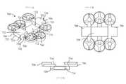
可動オブジェクトの構成の変形に関するシステム及び方法が本明細書で説明される。可動オブジェクトは、無人航空機(UAV)などの無人機であってもよい。UAVに関する本明細書の説明は、任意の種類の可動オブジェクト、無人機、及び/又は航空機にも適用することができる。UAVは、トライコプター、クアッドコプター、ヘキサコプター、及び/又はオクトコプターを含むマルチローター航空機であってもよい。UAVは、中央本体から延在する複数のアームを備える中央本体を含むことができる。1つ又は複数の推進ユニットは、UAVのための揚力を発生させるために、複数のアームのそれぞれに連結されてもよい。UAVの中央本体は、第1の構成と第2の構成との間で変形するように構成することができる。第1の構成と第2の構成との間の変形中の中間段階などの、第1の構成と第2の構成との間の中間段階におけるUAVも本明細書で説明される。 Systems and methods for transforming the configuration of movable objects are described herein. The movable object may be an unmanned aerial vehicle (UAV) or the like. The description herein regarding UAVs can also be applied to any type of mobile object, unmanned aerial vehicle, and / or aircraft. The UAV may be a multirotor aircraft that includes a tricopter, a quadcopter, a hexacopter, and / or an octocopter. The UAV can include a central body with a plurality of arms extending from the central body. One or more propulsion units may be connected to each of the plurality of arms to generate lift for the UAV. The central body of the UAV can be configured to deform between the first configuration and the second configuration. UAVs in the intermediate stages between the first configuration and the second configuration, such as the intermediate stage during transformation between the first configuration and the second configuration, are also described herein.
UAVは、作動時ではない間に第1の構成であってもよく、かつ、作動中に第2の構成であってもよい。たとえば、UAVは、UAVの運搬中及び/又は収納中などの非作動モードである時、省スペース構成であってもよい。UAVは、電源オフ時、省スペース構成であってもよい。省スペース構成は、UAVの運搬及び/又は収納に使用される減少された空間に、作動中のUAVの構成モードに対してより小型であってもよく、かつ/又は、占有設置面積が縮小されていてもよい。いくつかの実施形態において、UAVは、飛行中などの作動モード中、展開構成であってもよい。いくつかの実施形態において、UAVは、電源オンの間、展開構成であってもよい。UAVは、展開構成において飛行のために構成されてもよい、たとえば、そのさまざまな構成要素がUAVの飛行を容易にする望ましい位置にある状態にあってもよい。 The UAV may have a first configuration during non-operation and a second configuration during operation. For example, the UAV may have a space-saving configuration when in a non-operating mode, such as during transport and / or storage of the UAV. The UAV may have a space-saving configuration when the power is turned off. The space-saving configuration may be smaller than the operating UAV configuration mode in the reduced space used for transporting and / or storing the UAV, and / or the occupied footprint is reduced. You may be. In some embodiments, the UAV may be in a deployed configuration during an operating mode, such as during flight. In some embodiments, the UAV may be in a deployed configuration during power-on. The UAV may be configured for flight in a deployed configuration, for example, its various components may be in desirable positions to facilitate the flight of the UAV.
UAVは、複数の中央本体部分を備える中央本体を備えてもよく、第1の構成と第2の構成との間でUAVを変形させるために、複数の中央本体部分のうちの1つ又は複数は、複数の中央本体部分のうちの他のものに対して移動するように構成されている。たとえば、中央本体は、第1の中央本体部分と第2の中央本体部分とを備えることができ、第1の構成と第2の構成との間で中央本体の変形をもたらすために、中央本体部分の一方又は両方は、他方に対して移動するように構成することができる。いくつかの実施形態において、第1の中央本体部分又は第2の中央本体部分は、他方に対して移動するように構成することができ、第1の構成と第2の構成の間で中央本体を変形させることができる。いくつかの実施形態において、第1の中央本体部分及び第2の中央本体部分はどちらも、中央本体を変形させるために、他方に対して移動する。いくつかの実施形態において、中央本体は、3つ、4つ、5つ、6つ、又はより多くの部分を含む、2つ以上の中央本体部分を備えてもよく、中央本体部分のうちの1つ又は複数は、中央本体を変形させるために、中央本体部分の1つ又は複数の他のものに対して移動することができる。複数の中央本体部分のそれぞれは、別個の、分離可能な部分とすることができる。たとえば、複数の中央本体部分のうちの1つ又は複数は、他の中央本体部分のうちの1つ又は複数から分離させて、それらに対して移動させ、第1の構成と第2の構成との間で中央本体を変形させることができる。複数の中央本体部分のうちの1つ又は複数は、他の中央本体部分の1つ又は複数に対して移動させることができ、それにより、複数の中央本体部分のうちの1つ又は複数の質量中心は、1つ又は複数の他の中央本体部分の質量中心に対して移動することができる。 The UAV may include a central body that includes a plurality of central body portions, and one or more of the plurality of central body portions in order to transform the UAV between the first configuration and the second configuration. Is configured to move relative to the other of the plurality of central body parts. For example, the central body may include a first central body portion and a second central body portion to provide a deformation of the central body between the first configuration and the second configuration. One or both of the parts can be configured to move relative to the other. In some embodiments, the first central body portion or the second central body portion can be configured to move relative to the other and the central body between the first and second configurations. Can be transformed. In some embodiments, both the first central body portion and the second central body portion move relative to the other in order to deform the central body. In some embodiments, the central body portion may comprise two or more central body portions, including three, four, five, six, or more portions, of the central body portions. One or more can be moved relative to one or more of the central body portions to deform the central body. Each of the plurality of central body parts can be a separate, separable part. For example, one or more of the plurality of central body parts may be separated from one or more of the other central body parts and moved relative to them, with the first configuration and the second configuration. The central body can be deformed between. One or more of the central body parts can be moved relative to one or more of the other central body parts, whereby the mass of one or more of the central body parts The center can move relative to the center of mass of one or more other central body portions.
いくつかの実施形態において、複数の中央本体部分のうちの1つ又は複数は、UAVを作動させるための1つ又は複数の電子部品を収容するための内部空間をその中に収める又は実質的に収めるように構成された別個の部分とすることができる。たとえば、複数の中央本体部分のそれぞれは、それぞれの内部空間をその中に提供するように構成することができ、UAVを作動させるための1つ又は複数の電子部品は、内部空間に収容することができる。本明細書で説明されるように、いくつかの実施形態において、中央本体部分のうちの1つ又は複数は、各中央本体部分のそれぞれの内部空洞に収容された電子部品間の通信を容易にする1つ又は複数の電気的インタフェースを備えることができる。 In some embodiments, one or more of the central body portions will contain or substantially contain an internal space for accommodating one or more electronic components for operating the UAV. It can be a separate part configured to fit. For example, each of the plurality of central body parts can be configured to provide its own interior space within it, and one or more electronic components for operating the UAV may be housed in the interior space. Can be done. As described herein, in some embodiments, one or more of the central body portions facilitates communication between electronic components housed in their respective internal cavities of each central body portion. It can be equipped with one or more electrical interfaces.
いくつかの実施形態において、複数の中央本体部分のうちの1つ又は複数は、第1の構成と第2の構成との間で中央本体部分を変形させるために、複数の中央本体部分の1つ又は複数の他のものに対して並進的に移動することができる。複数の中央本体部分のうちの1つ又は複数は、変形中及び変形後にその向きを維持することができる。たとえば、1つ又は複数の中央本体部分は、変形中、回転しなくてもよく、それにより、1つ又は複数の中央本体部分の向きは、変形の前後で同じである。いくつかの実施形態において、複数の中央本体部分のうちの1つ又は複数は、他の中央本体部分のうちの1つ又は複数に対して、並進的にかつ回転可能に移動することができる。たとえば、第1の中央本体部分及び第2の中央本体部分のそれぞれの部分は、変形中及び/又は変形後、互いに対して並進的にかつ回転可能に移動してもよい。 In some embodiments, one or more of the plurality of central body portions is one of the plurality of central body portions in order to deform the central body portion between the first configuration and the second configuration. It can move translationally with respect to one or more others. One or more of the plurality of central body portions can maintain their orientation during and after deformation. For example, the one or more central body portions do not have to rotate during the deformation, so that the orientation of the one or more central body portions is the same before and after the deformation. In some embodiments, one or more of the plurality of central body parts can move translationally and rotatably with respect to one or more of the other central body parts. For example, each portion of the first central body portion and the second central body portion may move translationally and rotatably with respect to each other during and / or after deformation.
いくつかの実施形態において、第1の構成と第2の構成との間で変形することは、第1の構成と第2の構成との間で中央本体を変形させるために、1つ又は複数の他の中央本体部分に対して複数の中央本体部分のうちの1つ又は複数を横方向及び/又は縦方向に移動させることを含む。たとえば、1つ又は複数の中央本体部分は、変形中、たとえば、UAVのピッチ軸及びロール軸のうちの1つ又は複数に沿って、別の中央本体部分の方へ又は別の中央本体部分から離れるように水平に移動してもよい。1つ又は複数の中央本体部分は、変形中、たとえば、UAVのヨー軸に沿って、上又は下に移動してもよい。いくつかの実施形態において、複数の中央本体部分のうちの1つ又は複数のすべての部分は、変形中及び/又は変形後、同じ又は略上同じそれぞれの平面内にとどまることができる。たとえば、複数の中央本体部分のうちの1つ又は複数の質量中心は、変形中及び/又は変形後、同じ又は略同じ平面内にとどまることができる。いくつかの実施形態において、複数の中央本体部分のうちの1つ又は複数は、変形中、上又は下に移動することができる。たとえば、複数の中央本体部分のうちの1つ又は複数の質量中心は、変形中及び/又は変形後、垂直に移動することができる。 In some embodiments, the transformation between the first configuration and the second configuration is one or more in order to transform the central body between the first configuration and the second configuration. Includes moving one or more of a plurality of central body parts laterally and / or vertically relative to other central body parts. For example, one or more central body parts are being deformed, eg, along one or more of the pitch and roll axes of the UAV, towards or from another central body part. It may be moved horizontally so as to be separated. One or more central body portions may move up or down during deformation, eg, along the yaw axis of the UAV. In some embodiments, one or all of the central body portions may remain in the same or substantially the same plane during and / or after the transformation. For example, one or more centers of mass of a plurality of central body portions can remain in the same or substantially the same plane during and / or after deformation. In some embodiments, one or more of the plurality of central body portions can be moved up or down during deformation. For example, the center of mass of one or more of the central body portions can move vertically during and / or after deformation.
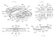
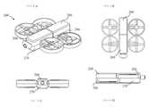
いくつかの実施形態において、複数の中央本体部分のうちの1つ又は複数は、第1の構成と第2の構成との間で中央本体を変形させるために、直線又は略直線線形部分を備える経路に沿って移動することができる。いくつかの実施形態において、経路は直線又は略直線である。いくつかの実施形態において、複数の中央本体部分のうちの1つ又は複数は、中央本体を変形させるために、直線及び円弧状経路を含む、直線及び湾曲経路に沿って移動することができる。いくつかの実施形態において、中央本体を変形させることは、第1の中央本体部分及び第2の中央本体部分のうちの1つ又は複数を他に対して並進的に移動させることと、第1の中央本体部分及び第2の中央本体部分のうちの1つ又は複数を円弧状経路などの湾曲経路に沿って移動させることとを含む。いくつかの実施形態において、第1の中央本体部分及び第2の中央本体部分のうちの1つ又は複数を直線経路に沿って移動させることにより、中央本体は第1の構成から第2の構成に変形し、又は、逆も又同じである。いくつかの実施形態において、第1の中央本体部分及び第2の中央本体部分のうちの1つ又は複数をS字状経路に沿って移動させることにより、中央本体は第1の構成から第2の構成に変形し、又は、逆も又同じである。第1の中央本体部分及び第2の中央本体部分のうちの1つ又は複数は、第1の構成と第2の構成との間でUAVを変形させるために、UAVのロール軸、ピッチ軸、及びヨー軸のうちの1つ又は複数に沿って移動してもよい。第1の中央本体部分及び第2の中央本体部分のうちの1つ又は複数は、第1の構成と第2の構成との間でUAVを変形させるために、UAVのロール軸、ピッチ軸、及びヨー軸のうちの1つ又は複数に沿って移動してもよく、それらの軸のまわりを回転してもよい。UAVは、その中央本体から延在する1つ又は複数の変形可能なアームを含むことができる。変形可能なアームは、第1の構成と第2の構成との間で変形するように構成することができる。たとえば、変形可能なアームは、省スペース構成と展開構成との間で変形することができる。省スペース構成は、UAVの運搬及び/又は収納に使用される減少された空間に、展開構成に対してより小型であってもよく、かつ/又は、占有設置面積が縮小されていてもよい。変形可能なアームは、UAVの運搬中及び/又は収納中などの非作動モードの間、省スペース構成であってもよい。変形可能なアームは、UAVの電源がオフである時を含むUAVが飛行中ではない時、省スペース構成であってもよい。いくつかの実施形態において、変形可能なアームは、UAVの飛行中など作動モードの間、展開構成であってもよい。いくつかの実施形態において、変形可能なアームは、電源オンの間、展開構成であってもよい。変形可能なアームは、展開構成において飛行のために構成されてもよい、たとえば、そのさまざまな構成要素がUAVの飛行を容易にする望ましい位置にある状態にあってもよい。本明細書に説明される1つ又は複数のUAVは、1つ又は複数の変形可能なアームを備えてもよい。たとえば、変形可能な中央本体を備えるUAVは、変形可能な中央本体から延在する複数の変形可能なアームを備えてもよい。 In some embodiments, one or more of the plurality of central body portions comprises a straight or substantially linear linear portion to deform the central body between the first configuration and the second configuration. You can move along the path. In some embodiments, the path is straight or substantially straight. In some embodiments, one or more of the central body portions can move along straight and curved paths, including straight and arcuate paths, to deform the central body. In some embodiments, deforming the central body involves moving one or more of the first central body portion and the second central body portion in translation with respect to the other. This includes moving one or more of the central body portion and the second central body portion of the above along a curved path such as an arcuate path. In some embodiments, the central body is configured from the first configuration to the second configuration by moving one or more of the first central body portion and the second central body portion along a linear path. And vice versa. In some embodiments, the central body is made from the first configuration to the second by moving one or more of the first central body portion and the second central body portion along an S-shaped path. And vice versa. One or more of the first central body portion and the second central body portion is a roll axis, pitch axis, of the UAV, in order to deform the UAV between the first configuration and the second configuration. And may move along one or more of the yaw axes. One or more of the first central body portion and the second central body portion is a roll axis, pitch axis, of the UAV, in order to deform the UAV between the first configuration and the second configuration. And may move along one or more of the yaw axes and may rotate around those axes. The UAV may include one or more deformable arms extending from its central body. The deformable arm can be configured to be deformable between the first configuration and the second configuration. For example, the deformable arm can be deformed between a space-saving configuration and a deployment configuration. The space-saving configuration may be smaller than the deployment configuration and / or the occupied footprint may be reduced in the reduced space used for transporting and / or storing the UAV. The deformable arm may have a space-saving configuration during non-operational modes such as during transport and / or storage of the UAV. The deformable arm may have a space-saving configuration when the UAV is not in flight, including when the UAV is powered off. In some embodiments, the deformable arm may be in a deployed configuration during an operating mode, such as during a UAV flight. In some embodiments, the deformable arm may be in a deployed configuration during power-on. The deformable arm may be configured for flight in a deployed configuration, for example, its various components may be in the desired position to facilitate the flight of the UAV. The one or more UAVs described herein may include one or more deformable arms. For example, a UAV with a deformable central body may include a plurality of deformable arms extending from the deformable central body.
変形可能なアームは、第1のアーム部分と第2のアーム部分とを備えてもよく、第1のアーム部分及び第2のアーム部分のうちの1つ又は複数は、第1の構成と第2の構成との間でアームを変形させるために、第2のアーム部分に対して並進的に移動するように構成されている。たとえば、変形可能なアームは、省スペース構成においてよりも展開構成において、より長い長さを有することができる。第1のアーム部分及び第2のアーム部分のうちの1つ又は複数は、第1の構成と第2の構成との間で変形可能なアームを変形させるために、変形可能なアームの長さに平行又は略平行の経路に沿って、他のものに対して移動させることができる。第1のアーム部分は、たとえば、中央本体から遠位の遠位部分で、第1の推進ユニットを支持してもよく、第2のアームは、たとえば、中央本体から遠位の遠位部分で、第2の推進ユニットを支持してもよい。推進ユニットのそれぞれは、回転翼羽根の組に連結された回転翼を備えてもよい。第1の構成では、第1の推進ユニットが第2の推進ユニットの上に配置されて、第2の推進ユニットの向きと反対の方向に向けられるように、第1のアーム部分は第2のアーム部分の上に配置されてもよい。たとえば、第1のアーム部分は、第2のアーム部分の上に並べて配置されてもよい。第1のアーム部分及び第2のアーム部分のうちの1つ又は複数は、第1の構成と第2の構成との間でアームを変形させるために、他のものに対して並進的に移動することができる。たとえば、第2の構成では、第1のアーム部分及び第2のアーム部分は、第1のアーム部分の遠位部分上に支持された第1の推進ユニットが第2のアーム部分の遠位部分上に支持された第2の推進ユニットの上に配置されないように、互いから並進的に移動することができる。第1のアーム部分及び第2のアーム部分は、第2の構成において、UAVの作動を容易にするように、たとえば、UAVの飛行を可能にするように、互いに対して位置付けることができる。 The deformable arm may include a first arm portion and a second arm portion, and one or more of the first arm portion and the second arm portion may have a first configuration and a first. It is configured to move translationally with respect to the second arm portion in order to deform the arm with and from the second configuration. For example, the deformable arm can have a longer length in a deployed configuration than in a space-saving configuration. One or more of the first arm portion and the second arm portion is the length of the deformable arm in order to deform the deformable arm between the first configuration and the second configuration. It can be moved relative to others along a path parallel to or substantially parallel to. The first arm portion may support the first propulsion unit, for example, in the distal portion distal to the central body, and the second arm may be, for example, in the distal portion distal to the central body. , The second propulsion unit may be supported. Each of the propulsion units may include rotor blades connected to a set of rotor blades. In the first configuration, the first arm portion is second so that the first propulsion unit is placed on top of the second propulsion unit and oriented in the direction opposite to the orientation of the second propulsion unit. It may be placed on the arm portion. For example, the first arm portion may be arranged side by side on the second arm portion. One or more of the first arm portion and the second arm portion move translationally with respect to the other in order to deform the arm between the first configuration and the second configuration. can do. For example, in the second configuration, the first arm portion and the second arm portion are such that the first propulsion unit supported on the distal portion of the first arm portion is the distal portion of the second arm portion. They can move translationally from each other so that they are not placed on top of a second propulsion unit supported above. The first arm portion and the second arm portion can be positioned relative to each other in the second configuration to facilitate the operation of the UAV, eg, to allow the UAV to fly.
いくつかの実施形態において、UAVは、変形するように構成されていない1つ又は複数のアームを備えることができる。1つ又は複数であるアームは、UAVの中央本体が第1の構成と第2の構成との間で変形する間、同じ構成を維持してもよい。たとえば、UAVは、UAVの中央本体が第1の構成と第2の構成との間で変形する間、変形しない複数のアームを備えてもよい。いくつかの実施形態において、複数のアームのそれぞれは、中央本体の対応する部分と一体的に形成することができる。 In some embodiments, the UAV may include one or more arms that are not configured to deform. The one or more arms may maintain the same configuration while the central body of the UAV transforms between the first and second configurations. For example, the UAV may include a plurality of arms that do not deform while the central body of the UAV deforms between the first and second configurations. In some embodiments, each of the plurality of arms can be formed integrally with the corresponding portion of the central body.
本明細書のUAVは第1の中央本体部分及び第2の中央本体部分に関して説明されているが、UAVが2つより多い中央本体部分を備えてもよいことは気付かれるであろう。本明細書で説明されるUAVは四辺形状を有するように説明されるが、説明は別の形状を有するUAVに適用してもよいことが理解されよう。 Although the UAVs herein are described with respect to a first central body portion and a second central body portion, it will be noticed that the UAV may include more than two central body portions. Although the UAVs described herein are described as having a quadrilateral shape, it will be appreciated that the description may apply to UAVs with different shapes.
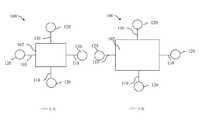
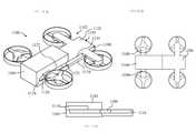
図1は、UAV100の概略図である。パートAは第1の構成のUAVを示し、パートBは第2の構成のUAVを示す。いくつかの実施形態において、第1の構成は省スペース構成である可能性がある。いくつかの実施形態において、第2の構成は展開構成である可能性がある。展開構成は、省スペース構成より小型ではない可能性があり、かつ/又は、省スペース構成より大きい設置面積を有する可能性がある。本明細書で説明されるように、省スペース構成は、UAVの収納及び/又は運搬を容易にすることができる。展開構成は、飛行などのUAVの作動に適している可能性がある。UAVは、省スペース構成での飛行のために構成されていなくてもよい。たとえば、UAVは、省スペース構成である時、飛行が可能でなくてもよいが、それは、たとえば、UAVは省スペース構成では電源がオフであるように構成されているためである。UAVは、UAVが省スペース構成である間の飛行を防止する1つ又は複数の安全機構を含んでもよい。たとえば、UAVは、UAVが意図せずに展開構成になる、かつ/又は、電源がオンになることを防止する1つ又は複数の安全機構を含んでもよい。いくつかの実施形態において、UAVは、UAVが展開構成になるまで、飛行を開始しなくてもよい。 FIG. 1 is a schematic view of the
UAV100は、中央本体102と、中央本体102から延在する複数のアーム110とを備えてもよい。複数のアームのそれぞれは、それぞれの推進ユニット120を支持することができる。推進ユニットは、揚力を発生するように構成させることができ、中央本体から遠位のアームの遠位部分の上で支持されてもよい。中央本体は、複数の中央本体部分を備えてもよく、中央本体部分のうちの1つ又は複数は、第1の構成と第2の構成との間で中央本体を変形させるために移動するように構成されている。いくつかの実施形態において、複数のアームのうちの1つ又は複数は、第1の構成と第2の構成との間で変形するように構成することができる。本明細書にさらに詳細に説明されているように、アームは、複数のアーム部分を備えることができ、アーム部分のうちの1つ又は複数は、第1の構成と第2の構成との間でアームを変形させるために、他のアーム部分に対して移動するように構成することができる。 The
いくつかの実施形態において、省スペース構成のUAV100は、展開構成の対応する寸法より小さい寸法を有することができる。省スペース構成の寸法は、展開構成の対応する寸法より最大約50%短くてもよく、最大約40%、最大約30%、最大約20%、最大約10%、約5%〜約50%、約10%〜約50%、約20%〜約50%、約30%〜約50%、又は、約40%〜約50%短い場合も含む。いくつかの実施形態において、寸法は、UAVのロール軸に平行又は略平行な方向に沿って延在する寸法などの、中央本体102の長さでもよい。いくつかの実施形態において、寸法は、UAVのピッチ軸に平行又は略平行な方向に沿って延在する寸法などの、中央本体の幅でもよい。たとえば、UAVの設置面積は、中央本体の幅及び/又は長さの増加により、省スペース構成から展開構成へと増大してもよい。いくつかの実施形態において、中央本体の高さである、UAVのヨー軸に平行又は略平行な方向に沿って延在するそのような寸法は、変形中及び/又は変形後に同じである可能性がある。たとえば、中央本体の高さは、省スペース構成及び展開構成で同じ又は略同じであってもよく、一方、中央本体の長さ及び/又は幅は、省スペース構成よりも展開構成において大きい。いくつかの実施形態において、中央本体の高さは、省スペース構成よりも展開構成において小さくなる可能性がある。たとえば、中央本体の高さは、省スペース構成から展開構成への変形において減少する可能性があり、一方、中央本体の長さ及び/又は幅は増加する。 In some embodiments, the space-saving configuration UAV100 can have dimensions smaller than the corresponding dimensions of the deployment configuration. The dimensions of the space-saving configuration may be up to about 50% shorter than the corresponding dimensions of the unfolded configuration, up to about 40%, up to about 30%, up to about 20%, up to about 10%, about 5% to about 50%. , About 10% to about 50%, about 20% to about 50%, about 30% to about 50%, or about 40% to about 50% shorter. In some embodiments, the dimension may be the length of the
いくつかの実施形態において、UAV100は、第1の構成及び/又は第2の構成において、複数の中央本体部分を望ましい位置に維持することを容易にする1つ又は複数の固定機構を備えてもよい。固定機構は、ラッチ機構、ソケット及びプラグ機構、ならびに電磁連結機構のうちの1つ又は複数を備えてもよい。たとえば、中央本体102は、固定機構の第1の部分を備える第1の中央本体部分と、固定機構の第2の対応する部分を備える第2の中央本体部分とを備えてもよい。いくつかの実施形態において、複数の中央本体部分のそれぞれは、1つ又は複数の固定機構のそれぞれの部分を備えることができる。いくつかの実施形態において、UAV100は、複数の中央本体部分のうちの1つ又は複数の、中央本体部分のうちの別の中央本体部分に対する移動を案内する1つ又は複数のガイド機能を備えてもよい。ガイド機能は、第1の中央本体部分を第2の中央本体部分に連結し、同時に、第1の中央本体部分及び第2の中央本体部分のうちの1つ又は複数の、他方に対する摺動移動などの移動を可能にする1つ又は複数の機構を備えてもよい。いくつかの実施形態において、ガイド機能は、第1の中央本体部分の第1の表面から延在する突起と、第2の中央本体部分の対応する表面上の対応する凹部とを備えてもよい。たとえば、第1の中央本体部分は、第1の中央本体部分上のレール機能と、レール機能と嵌合する第2の中央本体部分上の対応する凹部とを備えてもよく、それにより、第1の中央本体部分及び第2の中央本体部分のうちの1つ又は複数は、レールと凹部との嵌合によって案内される間、他方に対して摺動可能に移動することができる。いくつかの実施形態において、ガイド機能は、溝形コネクタ及びスライド可能なヒンジコネクタのうちの1つ又は複数を備えてもよい。 In some embodiments, the
いくつかの実施形態において、複数の中央本体部分のうちの1つ又は複数を中央本体部分の別の中央本体部分に対して並進的に移動させることにより、第1の構成と第2の構成との間で中央本体102を変形させることができる。第1の構成と第2の構成との間で中央本体を変形させるための、中央本体部分の別の中央本体部分に対する複数の中央本体部分のうちの1つ又は複数の並進移動は、直線経路及び湾曲経路のうちの1つ又は複数に沿って1つ又は複数の中央本体部分を移動させることを含むことができる。いくつかの実施形態において、複数の中央本体部分のうちの1つ又は複数は、直線経路及び直線及び湾曲経路のうちの1つ又は複数に沿って移動することができる。いくつかの実施形態において、複数の中央本体部分のうちの1つ又は複数は、直線経路及び円弧状経路に沿って移動することができる。いくつかの実施形態において、複数の中央本体部分のうちの1つ又は複数は、S字状経路に沿って移動することができる。複数の中央本体部分のうちの1つ又は複数は、第1の構成と第2の構成との間で中央本体102を変形させるために、中央本体部分の別の中央本体部分の方へ又は中央本体部分の別の中央本体部分から離れるように移動することができる。本明細書にさらに詳細に説明されているように、複数の中央本体部分のうちの1つ又は複数は、第1の構成と第2の構成との間で中央本体を変形させるために、垂直方向及び/又は水平方向に沿って移動してもよい。 In some embodiments, a first configuration and a second configuration are made by moving one or more of the plurality of central body portions in translation with respect to another central body portion of the central body portion. The
いくつかの実施形態において、中央本体102の複数の中央本体部分のうちの1つ又は複数は、第1の構成と第2の構成との間の変形中及び/又は変形後、同じ向きを維持することができる。いくつかの実施形態において、1つ又は複数の中央本体部分は、変形の前後に、同じ又は略同じ向きを有することができる。たとえば、1つ又は複数の中央本体部分は、変形中は向きを変え、一方で、変形の前後で同じ向きを有することができる(たとえば、前の位置に対して並進的に移動する曲率を備える経路に沿った移動)。いくつかの実施形態において、1つ又は複数の中央本体部分は、変形中及び/又は変形後、異なる向きを有することができる。 In some embodiments, one or more of the plurality of central body portions of the
いくつかの実施形態において、第2の構成のUAV100は、第1の構成では存在しない1つ又は複数の付加的な収納空間を備えることができる。いくつかの実施形態において、中央本体102は、第2の構成において1つ又は複数の付加的な収納空間を備えることができ、1つ又は複数の付加的な収納空間は、UAVの1つ又は複数の中央本体部分の1つ又は複数の表面によって少なくとも部分的に画定されている。たとえば、第1の構成において暴露されていない表面が第2の構成において暴露されてもよい。付加的な収納空間は、1つ又は複数のそのような表面によって少なくとも部分的に画定されてもよい。1つ又は複数の機能モジュールは、付加的な収納空間に収容されてもよい。たとえば、機能モジュールは、第1の構成では暴露されない、第2の構成で暴露される中央本体の1つ又は複数の表面に連結されてもよい。 In some embodiments, the
いくつかの実施形態において、機能モジュールは1つ又は複数のセンサを備える。たとえば、1つ又は複数のセンサは、1つもしくは複数のジャイロスコープ、慣性測定ユニット(IMU)、質量センサ、加速度計、磁気計、全地球測位システム(GPS)受信機、これらの組合せ、及び/又は、同様のものを備えてもよい。いくつかの実施形態において、機能モジュールは、バッテリなどのエネルギ源を備える。バッテリは、予備エネルギ及び/又は付加的なエネルギ源を提供するように構成された補助バッテリであってもよい。いくつかの実施形態において、バッテリは一次エネルギ源であってもよい。 In some embodiments, the functional module comprises one or more sensors. For example, one or more sensors include one or more gyroscopes, inertial measurement units (IMUs), mass sensors, accelerometers, magnetometers, Global Positioning System (GPS) receivers, combinations thereof, and /. Alternatively, a similar one may be provided. In some embodiments, the functional module comprises an energy source such as a battery. The battery may be an auxiliary battery configured to provide reserve energy and / or additional energy sources. In some embodiments, the battery may be the primary energy source.
いくつかの実施形態において、変形プロセスの開始及び/又は完了により、UAV100による機能の実行を開始することができる。いくつかの実施形態において、機能の実行は、変形プロセス中に行うことができる。本明細書で説明される変形プロセスは、UAVの中央本体102と、UAVの複数のアーム110のうちの1つ又は複数とを変形させることに関する可能性がある。機能は、UAVを電源オン状態にするためにUAVの電源をオンにすること、又は、UAVを電源オフ状態にするためにUAVの電源をオフにすることを含んでもよい。いくつかの実施形態において、機能は、UAVの1つ又は複数の構成要素を開始することを含んでもよい。いくつかの実施形態において、UAVの1つ又は複数の推進ユニット120は、変形の開始、実行、及び/又は完了に応答して、開始されてもよく及び/又は電源をオンにされてもよい。いくつかの実施形態において、1つ又は複数の電子部品は、変形の開始、実行、及び/又は完了に応答して、開始されてもよく及び/又は電源をオンにされてもよく、たとえば、UAVの制御装置が開始されてもよい。いくつかの実施形態において、変形プロセスの1つ又は複数のステップを完了することは、機能の実行をトリガすることができる。いくつかの実施形態において、中央本体部分の別のものに対する複数の中央本体部分のうちの1つ又は複数の移動、及び/又は、アームの別の部分に対するアームのアーム部分のうちの1つ又は複数の移動は、機能の実行をトリガすることができる。 In some embodiments, the initiation and / or completion of the transformation process can initiate the execution of the function by the UAV100. In some embodiments, the performance of the function can be performed during the transformation process. The transformation process described herein may involve transforming the
いくつかの実施形態において、機能の実行により、変形プロセスの開始をトリガしてもよい。たとえば、変形プロセスは、機能の開始及び/又は完了に応答して自動的に実行されてもよい。いくつかの実施形態において、UAV100の電源オン又は電源オフにより、変形プロセスをトリガすることができる。たとえば、UAVの電源オンにより、中央本体102及び/又はアーム110のうちの1つもしくは複数の変形など、UAVの展開構成への変形をトリガすることができる。UAVの電源オフにより、中央本体及び/又はアームのうちの1つもしくは複数の変形など、UAVの省スペース構成への変形をトリガすることができる。いくつかの実施形態において、UAVの1つ又は複数の構成要素の開始により、変形プロセスをトリガしてもよい。たとえば、作動のためにUAVの推進ユニット120の1つ又は複数を開始することは、UAVの変形をトリガすることができる。いくつかの実施形態において、推進ユニットの1つ又は複数の作動の停止は、展開構成から省スペース構成へのUAVの変形をトリガすることができる。たとえば、省スペース構成へのUAVの変形は、推進ユニットの作動停止後、たとえば推進ユニットの回転翼羽根の回転停止後に開始してもよい。いくつかの実施形態において、電子部品のうちの1つ又は複数の開始、たとえば、中央本体部分のうちの1つ又は複数の中に収容された1つ又は複数の電子部品の開始により、変形をトリガしてもよい。 In some embodiments, the execution of the function may trigger the start of the transformation process. For example, the transformation process may be performed automatically in response to the start and / or completion of the function. In some embodiments, powering on or off the
いくつかの実施形態において、変形プロセスの開始は、ユーザ命令によってトリガすることができる。たとえば、ユーザは、UAV100に変形の実行を指示する入力を提供してもよい。入力は、中央本体102及び/又は1つもしくは複数のアーム110上などの、UAV上の入力インタフェース機能(たとえば、押しボタン、スイッチ、モーションセンサ、及び/又は接触センサ)を介して受け取られてもよい。入力は、遠隔制御を介して受け取られてもよい。たとえば、ユーザは、変形プロセスを開始するために、UAVを変形させる命令を遠隔で入力してもよい。いくつかの実施形態において、複数の中央本体部分の複数の中央本体部分相対的別のもののうちの1つ又は複数、及び/又は、アームの1つもしくは複数のアーム部分の手動移動により、変形プロセスの実行をトリガすることができる。たとえば、ユーザは、第2の中央本体部分に対して第1の中央本体部分を移動させてもよく、応答して、UAVは、変形プロセスを開始及び/又は継続してもよい。 In some embodiments, the initiation of the transformation process can be triggered by a user command. For example, the user may provide the
いくつかの実施形態において、UAV100は、1つ又は複数の検出された状態に応答してUAVを変形させる命令信号を生成する構成された1つ又は複数の制御装置を備えることができる。状態は、UAVの1つ又は複数のセンサで検出されてもよい。いくつかの実施形態において、状態は、1つ又は複数の高度(たとえば、UAVが地面と接触している場合又は飛行中の場合)、UAVの向き(たとえば、IMUからの情報)、位置(たとえば、GPS情報に基づく)、エネルギ蓄積デバイスパワーレベル(たとえば、バッテリに残るエネルギ)を含むことができる。UAVは、1つ又は複数のトリガ条件に応じて、変形プロセスを自動的に開始してもよい。たとえば、UAVの制御装置は、トリガ条件の存在を示す1つ又は複数のセンサからの状態情報の受信に応答して、第1の構成又は第2の構成に変形する命令信号を生成してもよい。いくつかの実施形態において、UAVは、地面との接触、及び/又は、閾値レベルより低いバッテリエネルギ残量レベルの検出時に、省スペース構成への変形を開始してもよい。いくつかの実施形態において、UAVは、GPS位置情報に基づく目的地への到達の検出時に、展開構成への変形を開始してもよい。 In some embodiments, the
いくつかの実施形態において、変形の完了を検出するUAV100の制御装置(図示せず)は、機能の実行をトリガすることができる。変形の1つ又は複数のステップの完了の制御装置による検出は、機能の実行をトリガすることができる。UAVは、展開構成である間、電源オンであってもよい。UAVは、省スペース構成では、電源オフであってもよい。たとえば、中央本体が展開構成への変形プロセスを完了した場合を含めて、中央本体102が展開構成であることを制御装置が検出した場合、制御装置は電源オンプロセスを開始してもよい。中央本体が省スペース構成への変形を完了した場合を含めて、中央本体が省スペース構成であることを制御装置が検出した場合、制御装置は電源オフプロセスを開始してもよい。いくつかの実施形態において、UAVは、電源オフ後に、省スペース構成に変形されてもよい。いくつかの実施形態において、UAVは、展開構成への変形の開始前に、電源オンにされてもよい。 In some embodiments, a UAV100 controller (not shown) that detects the completion of the transformation can trigger the execution of a function. Detection by the controller of the completion of one or more steps of deformation can trigger the execution of a function. The UAV may be powered on during the deployment configuration. The UAV may be powered off in a space-saving configuration. For example, if the control unit detects that the
いくつかの実施形態において、以下のうちの1つ又は複数は、UAV100の電源オンなどの、機能の実行をトリガすることができる。(1)中央本体102を展開構成に維持する固定機構の係止、(2)中央本体上の付加的な空間内の、付加的な機能モジュールなどの付加的な電子部品の存在の接触センサによる検出、(3)付加的な電子部品との電気通信の開始、及び(4)中央本体の隣接部間の電気通信の停止。いくつかの実施形態において、複数の中央本体部分のうちの1つ又は複数の移動は、中央本体を望ましい構成に維持する固定機構の係止、付加的な機能モジュールとの電気通信の開始、及び/又は、中央本体の隣接部間の電気通信の停止をトリガすることができる。 In some embodiments, one or more of the following can trigger the execution of a function, such as powering on the UAV100. (1) Locking of the fixing mechanism that keeps the
いくつかの実施形態において、UAV100は、電源オンプロセスに応答してさらなる機能を実行するように構成されてもよい。たとえば、UAVの電源オンの開始後及び/又は完了後、UAVは、電源オンの開始及び/又は完了に応答して、以下のうちの少なくとも1つを実行するように構成することができる。離陸手順、搭載物の構成の開始、搭載物を使用した任務の実行、UAV上のセンサの構成の開始、中央本体102を第1の構成又は第2の構成に維持する固定機構の係止。いくつかの実施形態において、搭載物は、撮像デバイス(たとえば、カメラ)である可能性があり、任務は、撮像デバイスを使用して対象オブジェクトの画像を取り込むことを含む。 In some embodiments, the
いくつかの実施形態において、以下のうちの1つ又は複数は、UAV100の電源オフなどの機能の実行をトリガすることができる。(1)中央本体を省スペース構成に維持する固定機構の係止、(2)中央本体の隣接部間の接触の接触センサによる検出、及び、(3)中央本体の隣接部間の電気通信の開始。 In some embodiments, one or more of the following can trigger the execution of a function such as powering off the
いくつかの実施形態において、UAV100の電源オン又は電源オフは、第1の構成と第2の構成との間での中央本体102の変形の開始前、開始中、及び/又は開始後に実行することができる。 In some embodiments, powering on or off the
いくつかの実施形態において、UAV100は、中央本体102の展開構成への変形を指示する信号を受信するように構成された制御装置(図示せず)を備え、信号に応答して、制御装置は、UAV100の電源をオンにする制御信号を生成することができる。いくつかの実施形態において、制御装置は、UAVの電源をオンにする命令を備える信号を受信し、信号に応答して、中央本体を展開構成に変形させる制御信号を生成するように構成することができる。いくつかの実施形態において、制御装置は、UAVの電源オン後、以下の制御信号のうちの少なくとも1つを自動的に生成するように構成することができる。離陸手順、UAV上のさまざまセンサの初期化、UAV上の搭載物の初期化、中央本体を展開構成又は省スペース構成に維持する固定機構の係止。いくつかの実施形態において、制御装置は、中央本体の省スペース構成への変形を指示する信号を受信し、信号に応答して、UAVの電源をオフにする制御信号生成することができる。いくつかの実施形態において、制御装置は、UAVの電源をオフにする命令を備える信号を受信し、信号に応答して、中央本体を省スペース構成に変形させる制御信号を生成するように構成することができる。 In some embodiments, the
いくつかの実施形態において、UAV100は、UAVを展開構成又は省スペース構成に維持するように構成された1つ又は複数の機械的及び/又は電子的機構を備えてもよい。たとえば、UAVは、変形プロセスの望ましくない発生を防止する1つ又は複数の安全機構を備えてもよい。UAVは、電源オンの間及び/又は飛行中、省スペース構成への変形を防止する安全機構を備えてもよい。UAVは、UAVの保管時などの電源オフの間、展開構成への変形を防止する安全機構を備えてもよい。安全機構は、UAVの望ましくない電源オン又は電源オフを防止してもよい。 In some embodiments, the
中央本体102は、さまざまな形状を備えることができる。いくつかの実施形態において、中央本体は、三角形、四角形、五角形、六角形、七角形、及び/又は八角形を含む多角形を備えてもよい。たとえば、中央本体の1つ又は複数の断面図は、正方形及び/又は長方形である可能性がある。いくつかの実施形態において、中央本体は、1つ又は複数の湾曲部分を備えることができる。いくつかの実施形態において、中央本体は、丸い形状を有することができる。いくつかの実施形態において、中央本体の1つ又は複数の断面図は、円及び/又は楕円を備えることができる。中央本体の異なる断面図は、異なる形状を備えてもよい。 The
変形可能な中央本体を備えるUAVのさらなる例は、図2〜12を参照して説明される。いくつかの実施形態において、図2〜12に関して説明されるUAVは、図1に関して説明されたUAV100の1つ又は複数の特徴を備える。 Further examples of UAVs with a deformable central body will be described with reference to FIGS. 2-12. In some embodiments, the UAV described with respect to FIGS. 2-12 has one or more features of the
図2は、第1の構成のUAV200の例の概略図を示し、図3は、第2の構成のUAV200の概略図を示す。第1の構成は省スペース構成である可能性があり、第2の構成は展開構成である可能性がある。 FIG. 2 shows a schematic view of an example of the UAV200 of the first configuration, and FIG. 3 shows a schematic view of the UAV200 of the second configuration. The first configuration may be a space-saving configuration and the second configuration may be a deployment configuration.
図2のパートAは、第1の構成のUAV200の透視図を示す。UAV200は、第1の中央本体部分204と第2の中央本体部分206とを備える中央本体202を有することができる。パートAに示される例において、第1の中央本体部分及び第2の中央本体部分はそれぞれ、第1の中央本体部分が4つの側壁222、224、226、228を有することができ、第2の中央本体部分が4つの側壁232、234、236(図示せず)、及び238(図示せず)を有することができるような四辺形状を有する可能性がある。いくつかの実施形態において、四辺形状は、第1の中央本体部分及び第2の中央本体部分の隣接する側壁が互いに垂直又は略垂直であるような長方形又は略長方形である可能性がある。たとえば、側壁222及び224は互いに垂直又は略垂直であり、側壁224及び226は互いに垂直又は略垂直であり、側壁226及び228は互いに垂直又は略垂直であり、側壁222及び228は互いに垂直又は略垂直である。いくつかの実施形態において、側壁232及び234は互いに垂直又は略垂直であり、側壁234及び236は互いに垂直又は略垂直であり、側壁236及び238は互いに垂直又は略垂直であり、側壁232及び238は互いに垂直又は略垂直である。 Part A of FIG. 2 shows a perspective view of the
中央本体202の第1の中央本体部分204及び第2の中央本体部分206のそれぞれは、そこから延在する複数のアーム208を備えることができる。図2のパートAを参照すると、第1の中央本体部分は、側壁224から延在する第1のアーム208と、側壁228から延在する第2のアーム208とを備えることができる。第2の中央本体部分は、側壁234から延在する第3のアーム208と、側壁238から延在する第4のアーム208とを備えることができる。各アーム208は、推進ユニット210を支持するように構成することができる。推進ユニット210は、回転翼212と、回転翼212に連結された回転翼羽根の組214とを備えることができる。回転翼の回転は、UAVのための揚力を発生させるための、回転翼羽根の組の回転になる可能性がある。図2のパートAに示されるように、推進ユニットは、UAVの中央本体から遠位のアームの遠位部分で支持することができる。各アーム208は、回転翼羽根の組などの、推進ユニットの1つ又は複数の構成要素を保護するように構成された回転翼羽根ガードに連結されてもよい。
Each of the first
第1の中央本体部分204から延在するアーム208に連結された推進ユニット210は、それらの回転翼羽根の組214が第2の中央本体部分206から延在するアームに連結された推進ユニットから離れて位置付けられるように向けることができる。たとえば、側壁224及び側壁234から延在するそれぞれのアームに連結された推進ユニットは、2つの推進ユニットの回転翼羽根が反対方向に向けられるように、反対の向きを有することができる。側壁228及び238から延在するそれぞれのアームに連結された推進ユニットは、2つの推進ユニットの回転翼羽根が反対方向に向けられるように、反対の向きを有することができる。推進ユニットは、垂直に、たとえば、UAV200のヨー軸に平行又は略平行な向きに向けられてもよい。 The
第1の構成では、第1の中央本体部分204は、UAV200の第2の中央本体部分206より上に位置付けることができ、たとえば、第1の中央本体部分のすべての部分は第2の中央本体部分のすべての部分より上にある。第1の中央本体部分及び第2の中央本体部分は、UAVのヨー軸に平行又は略平行な方向に沿って重ね合わせて位置付けることができる。いくつかの実施形態において、第1の中央本体部分及び第2の中央本体部分206は、垂直軸を共有することができる。たとえば、垂直軸はUAVのヨー軸である可能性があり、又は、垂直軸はUAVのヨー軸に平行もしくは略平行である可能性がある。いくつかの実施形態において、第1の中央本体の質量中心は、第2の中央本体の質量中心より上にあり、一直線に並べられる可能性がある。 In the first configuration, the first
いくつかの実施形態において、第1の中央本体部分204及び第2の中央本体部分206は、幅及び/又は長さなどの、類似の又は同じである1つ又は複数の寸法を備えることができる。たとえば、第1の中央本体部分及び第2の中央本体部分は、第1の中央本体部分がヨー軸に沿って又はUAVのヨー軸に平行もしくは略平行な方向に沿って、第2の中央本体部分より上に並べて位置付けることができるように、UAV200のロール軸及びピッチ軸に平行又は略平行な方向に延在する類似の又は同じ寸法を有することができる。たとえば、側壁222、224、226、及び228はそれぞれ、側壁232、234、236、及び238と同一平面上又は略同一平面上である可能性がある。 In some embodiments, the first
いくつかの実施形態において、第1の構成では、第1の中央本体部分204は、第1の中央本体部分及び第2の中央本体が互いに完全に重なり合うことができるように、第2の中央本体部分206より上に位置付けられてもよい。いくつかの実施形態において、第1の中央本体部分は、第1の中央本体部分及び第2の中央本体が互いに最大約90%、最大約80%、最大約70%、最大約60%、又は最大約50%の重なりを有することができるように、第2の中央本体部分より上に位置付けられてもよい。いくつかの実施形態において、第1の中央本体と第2の中央本体との重なりが増加することにより、第1の構成におけるUAV200の設置面積を縮小させることができる。 In some embodiments, in the first configuration, the first
アーム208は、第1の中央本体部分204及び第2の中央本体部分206のそれぞれの側壁上の類似の又は同じ位置から延在することができる。いくつかの実施形態において、第1の中央本体部分及び第2の中央本体部分から延在する対応するアーム208の長手方向軸は、長手方向軸が重ね合わせて位置付けられるように、互いに並べることができる。たとえば、側壁224及び側壁234から延在するアーム、ならびに、推進ユニット210及びアームに連結された回転翼羽根ガード216は、重ね合わせて位置付けることができ、それは、UAV200のヨー軸に平行又は略平行な方向に沿って互いに並べられることを含む。側壁228及び側壁238から延在するアーム、ならびに、推進ユニット及びアームに連結された回転翼羽根ガードは、重ね合わせて位置付けることができ、それは、UAV200のヨー軸に平行又は略平行な方向に沿って互いに並べられることを含む。
The
図2のパートBは、第1の構成のUAV200の下向き図である。図において、第1の中央本体部分204、第1の中央本体部分204から延在するアーム208、第1の中央本体部分から延在するアームに連結された回転翼羽根ガード216、ならびに、アームによって支持された回転翼212及び回転翼羽根の組214が示されている。第2の中央本体部分206、第2の中央本体部分から延在するアーム、第2の中央本体部分から延在するアームに連結された回転翼羽根ガード、ならびに、第2の中央本体部分から延在するアームによって支持された回転翼及び回転翼羽根の組は図2のパートBに示されていないが、第2の中央本体部分及び第2の中央本体部分に連結された構成要素はそれぞれ、第1の中央本体部分及び第1の中央本体部分に連結された構成要素の下に並べて位置付けられている。 Part B of FIG. 2 is a downward view of the
図2のパートCは、第1の構成のUAV200の正面図である。図2のパートDは、第1の構成のUAV200の側面図である。図2のパートC及びパートDに示されるように、第1の中央本体部分204は、第2の中央本体部分206の上に並べて、接触するように位置付けられて示されている。第1の中央本体部分から延在するアーム208に連結された回転翼羽根ガード216は、第2の中央本体部分から延在するアームに連結された対応する回転翼羽根ガードの上に並べて、接触するように位置付けられる。いくつかの実施形態において、第1の中央本体部分は、第2の中央本体部分の上に並べて、しかし、第2の中央本体部分とは接触はせずに、位置付けることができる。いくつかの実施形態において、第1の中央本体部分から延在するアームに連結された回転翼羽根ガードは、第2の中央本体部分206から延在するアームに連結された対応する回転翼羽根ガードの上に並べて、しかし接触はせずに位置付けることができる。 Part C of FIG. 2 is a front view of the
図3のパートAは第2の構成のUAV200の透視図である。図3のパートBは第2の構成のUAVの下向き図であり、図3のパートCは第2の構成のUAVの正面図であり、図3のパートDは第2の構成のUAVの側面図である。本明細書で説明されるように、第2の構成は展開構成である可能性がある。いくつかの実施形態において、UAVは、飛行中などの作動中、展開構成である可能性がある。UAVは、図2を参照して説明された第1の構成の間、第2の構成へ変形することができる。 Part A of FIG. 3 is a perspective view of the
第2の構成では、第1の中央本体部分204は、第2の中央本体部分206に対して並進的に移動することができる。第1の中央本体部分は、第2の構成において第2の中央本体部分より上に位置付けられたままである。たとえば、第1の中央本体部分及び第2の中央本体部分のうちの1つ又は複数は、第1の構成と第2の構成との間でUAV200を変形させるために、他のものに対して移動することができる。第1の中央本体部分及び第2の中央本体部分のうちの1つ又は複数は、第1の構成と第2の構成との間で中央本体を変形させるために、たとえば、UAVのロール軸に平行又は略平行な方向に沿って、水平に移動することができる。たとえば、第1の中央本体部分と第2の中央本体部分との間の垂直距離、ならびに、アーム208、推進ユニット210、及びそれに連結された回転翼羽根ガード216は、変形中及び変形後、同じ又は略同じままとすることができる。中央本体202の高さは、変形中及び変形後、同じ又は略同じままとすることができる。いくつかの実施形態において、UAVの高さは、変形中及び変形後、同じ又は略同じままとすることができる。第1の中央本体部分と第2の中央本体部分との間の垂直距離、ならびに、アーム、推進ユニット、及びそれに連結された回転翼羽根ガードは、第1の構成及び第2の構成において、ならびに/又は、第1の構成と第2の構成との間の変形中、同じ又は略同じとすることができる。いくつかの実施形態において、中央本体の幅は、変形中及び/又は変形後、同じ又は略同じままとすることができる。第1の中央本体部分及び第2の中央本体部分は、変形中及び/又は変形後、同じ又は略同じ向きを維持することができる。 In the second configuration, the first
いくつかの実施形態において、第1の中央本体部分204及び第2の中央本体部分206のうちの1つ又は複数は、第1の構成と第2の構成との間で中央本体202を変形させるために、他のものに対して直線的に又は略直線的に移動することができる。たとえば、図3のパートAに示されるように、第1の中央本体部分及び第1の中央本体部分から延在するアーム208は、第2の中央本体部分及び第2の中央本体部分から延在するアーム208に対して並進的に移動することができる。中央本体202の全長は、第1の構成においてよりも第2の構成においての方が大きい可能性がある。第1の中央本体部分及び第2の中央本体部分の一方又は両方は、並進移動を実現するために、直線又は略直線の経路に沿って、たとえば水平面において、移動することができる。たとえば、第1の中央本体部分の質量中心は、第2の中央本体部分の質量中心に対して、水平に移動することができる。第1の中央本体部分及び第2の中央本体部分の質量中心間の水平距離は、第1の構成においてよりも第2の構成においての方が大きい可能性がある。いくつかの実施形態において、側壁224及び234から延在するアーム間の水平距離、ならびに、側壁228及び238から延在するアーム間の水平距離は、第1の構成においてよりも第2の構成においての方が大きく、一方、垂直距離は同じ又は略同じままである。いくつかの実施形態において、第2の構成では、側壁224から延在するアームと側壁234から延在するアームとの間、及び/又は、側壁228から延在するアームと側壁238から延在するアームとの間で、水平距離は維持することができ、それにより、側壁224、234から延在するそれぞれのアームに連結された回転翼羽根214は重ならず、側壁228、238から延在するそれぞれのアームに連結された回転翼羽根214は重ならない。いくつかの実施形態において、第2の構成では、側壁224から延在するアームと側壁234から延在するアームとの間、及び/又は、側壁228から延在するアームと側壁238から延在するアームとの間で、水平距離は維持することができ、それにより、側壁224、234から延在するそれぞれのアームに連結された回転翼羽根ガード216は重ならず、側壁228、238から延在するそれぞれのアームに連結された回転翼羽根ガード216は重ならない。重なりの減少又は排除は、UAVのそれぞれのアームに連結された推進ユニット210による揚力の発生を容易にし、UAVの飛行を可能にすることができる。 In some embodiments, one or more of the first
第1の中央本体部分204は、上面246と下面248とを備えることができる。第2の中央本体部分206は、上面242と下面244とを備えることができる。いくつかの実施形態において、第2の中央本体部分は、第1のガイド機能を上面に備えることができ、第1の中央本体部分は、上面の第1のガイド機能に連結するように構成された下面上の第2の対応するガイド機能を備えることができる。ガイド機能は、第1の中央本体部分及び第2の中央本体部分のうちの1つ又は複数の他のものに対する移動を案内するように構成することができる。いくつかの実施形態において、ガイド機能は、第1の中央本体部分及び第2の中央本体部分の互いに対する望ましい位置の維持を容易にすることができる。 The first
第2の中央本体部分206は、上面242にガイドレール250を備えることができる。ガイドレールは、第1の中央本体部分204及び第2の中央本体部分のうちの1つ又は複数の他のものに対する移動を案内し、かつ/又は、第1の中央本体部分及び第2の中央本体部分の互いに対する望ましい位置を維持するように構成される可能性がある。第1の中央本体部分は、第2の中央本体部分の上面に向けられた、下面248上の対応する突起を備えてもよい。対応する突起は、第1の中央本体部分及び/又は第2の中央本体部分の移動を案内するために、ガイドレールと嵌合することができる。たとえば、ガイドレールは、直線又は略直線の経路に沿った第1の中央本体部分及び/又は第2の中央本体部分の移動を案内するように構成することができる。いくつかの実施形態において、ガイドレールは、第1の中央本体部分の下面にあってもよく、第2の中央本体部分は、ガイドレールと嵌合するために、上面に対応する突起を備えることができる。 The second
図3のパートBに、第2の中央本体部分206に対する第1の中央本体部分204の、及び、そこから延在する対応するアーム208の並進移動が示されている。第1の中央本体部分から延在するアームのうちの1つ又は複数、回転翼羽根ガード216、及びアームに連結された回転翼212及び回転翼羽根214が、第2の中央本体部分から延在するアームのうちの1つ又は複数、回転翼羽根ガード、及び第2の中央本体部分から延在するアームに連結された回転翼及び回転翼羽根に重ならない又は実質的に重ならないように、第1の中央本体部分は、第2の中央本体部分に対して並進的に移動することができる。たとえば、側壁228から延在するアーム、ならびに、側壁228から延在するアームに連結された回転翼、回転翼羽根の組、及び回転翼羽根ガードは、それぞれ、側壁238から延在するアーム、ならびに、側壁238から延在するアームに連結された回転翼、回転翼羽根の組、及び回転翼羽根ガードの任意の部分の上に位置付けられなくてもよい。 Part B of FIG. 3 shows the translational movement of the first
いくつかの実施形態において、第1の中央本体部分204の少なくとも一部は、第2の構成において、たとえば、図3のパートDに示されるように、第2の中央本体部分206の上に位置付けることができる。図3のパートDに示されるように、第1の中央本体部分204及び第2の中央本体部分206は、2つの間で重なり合う部分を維持しながら、互いに対して移動することができる。第1の中央本体部分と第2の中央本体部分との重なりの程度は、変えることができる。重なりは、第2の構成における望ましい安定性を提供するように、かつ/又は、第1の中央本体部分の電子部品と第2の中央本体部分の電子部品との間の電気通信を容易にするようにその間の望ましい接触を提供するように、選択することができる。第2の構成における第1の中央本体部分と第2の中央本体部分との重なりは、第1の構成における第1の中央本体部分と第2の中央本体部分との重なりより小さい可能性がある。いくつかの実施形態において、第1の中央本体部分及び第2の中央本体部分は、互いに最大約50%、最大約40%、最大約30%、最大約20%、又は、最大約10%の重なりを有することができる。いくつかの実施形態において、中央本体202の設置面積は、第2の構成において、最大約10%大きい、最大約20%大きい、最大約30%大きい、最大約40%大きい、最大約50%大きい、最大約60%大きい、最大約70%大きい、最大約80%大きい、又は、最大約90%大きい可能性がある。 In some embodiments, at least a portion of the first
いくつかの実施形態において、第2の構成のUAV200は、第1の構成では存在しない1つ又は複数の付加的な収納空間を備えることができる。いくつかの実施形態において、中央本体202は、第2の構成において1つ又は複数の付加的な収納空間を備えることができ、1つ又は複数の付加的な収納空間は、第1の中央本体部分204の1つ又は複数の表面及び第2の中央本体部分206の1つ又は複数の表面によって少なくとも部分的に画定されている。第1の構成では暴露されない第2の中央本体部分の上面の少なくとも一部及び/又は第1の中央本体部分の下面248の少なくとも一部が第2の構成で暴露されるように、第1の中央本体部分は、第2の中央本体部分に対して移動することができる。たとえば、付加的な収納空間は、第2の中央本体部分の上面242及び第1の中央本体部分の側壁226によって少なくとも部分的に画定することができる。本明細書でさらに詳細に説明されるように、機能モジュールは、付加的な収納空間に収容されてもよい。機能モジュールは、第1の構成では暴露されない、第2の構成で暴露される中央本体の1つ又は複数の表面に連結されてもよい。たとえば、機能モジュールは、第2の中央本体部分の上面及び/又は第1の中央本体部分の側壁226上の1つ又は複数の機械的インタフェース及び/又は電気的インタフェースを介して、中央本体に連結することができる。 In some embodiments, the
いくつかの実施形態において、付加的な収納空間は、第1の中央本体部分204の下面248及び第2の中央本体部分206の側壁232によって少なくとも部分的に画定することができる。機能モジュールは、この付加的な収納空間に収容することができる。たとえば、機能モジュールは、下面248及び/又は側壁322上の1つ又は複数の機械的インタフェース及び電気的インタフェースを介して、中央本体202に連結されてもよい。
In some embodiments, the additional storage space can be at least partially defined by the
図4は、第2の構成における、UAV200に連結された2つの機能モジュールを備えるUAV200の概略図を示す。図4のパートAは2つの機能モジュールを備えるUAVの透視図であり、図4のパートBは2つの機能モジュールを備えるUAVの下向き図であり、図4のパートCは2つの機能モジュールを備えるUAVの正面図であり、図4のパートDは2つの機能モジュールを備えるUAVの側面図である。パートAに示されるように、中央本体202は、中央本体202に連結された第1の機能モジュール260及び第2の機能モジュール270を備えることができる。第1の機能モジュール260は、第2の中央本体部分206の上面242及び/又は第1の中央本体部分204の側壁226に連結することができる。第2の機能モジュールは、第1の中央本体部分204の下面248及び第2の中央本体部分206の側壁232に連結することができる。1つ又は複数の電気的インタフェース及び/又は機械的インタフェースは、機能モジュールの中央本体への望ましい機械的連結及び/又は機能モジュールと中央本体との間の電気通信を提供するために、上面242、側壁226、下面248、及び側壁232のうちの1つ又は複数にあってもよい。機械的インタフェースは、機能モジュールへの機械的連結及び/又は機能モジュールの所定の位置への維持のための1つ又は複数の機能を備えてもよい。いくつかの実施形態において、機械的連結機構はラッチ機構を備える。いくつかの実施形態において、機械的連結機構は固定機構を備える。電気的インタフェースは、機能モジュールとUAVの1つ又は複数の他の電子部品との間の電気通信を提供するための1つ又は複数の電気接点を備えることができる。
FIG. 4 shows a schematic view of the
いくつかの実施形態において、機能モジュールは1つ又は複数のセンサを備える。たとえば、1つ又は複数のセンサは、1つもしくは複数のジャイロスコープ、慣性測定ユニット(IMU)、質量センサ、加速度計、磁気計、全地球測位システム(GPS)受信機、これらの組合せ、及び/又は、同様のものを備えてもよい。いくつかの実施形態において、機能モジュールは、バッテリなどのエネルギ源を備える。バッテリは、予備エネルギ及び/又は付加的なエネルギ源を提供するように構成された補助バッテリであってもよい。いくつかの実施形態において、バッテリは、UAV200のための一次エネルギ源であってもよい。 In some embodiments, the functional module comprises one or more sensors. For example, one or more sensors include one or more gyroscopes, inertial measurement units (IMUs), mass sensors, accelerometers, magnetometers, Global Positioning System (GPS) receivers, combinations thereof, and /. Alternatively, a similar one may be provided. In some embodiments, the functional module comprises an energy source such as a battery. The battery may be an auxiliary battery configured to provide reserve energy and / or additional energy sources. In some embodiments, the battery may be the primary energy source for the
付加的な収納空間を少なくとも部分的に画定する、第1の中央本体部分204及び第2の中央本体部分206の1つ又は複数の表面は、UAV200と付加的な収納空間内に収容された機能モジュールとの間の通信を提供するように構成された電気的インタフェースを備えてもよい。電気的インタフェースは、機能モジュールに電気エネルギを供給する、たとえば、機能モジュールに電力を供給する電気的結合を提供してもよい。電気的インタフェースは、機能モジュールからUAVへの(たとえば、UAVと1つ又は複数のセンサとの間の)データの通信を可能にするように構成されていてもよい。いくつかの実施形態において、電気的インタフェースは、機能モジュールと、UAVの航空制御器を含むUAVの1つ又は複数の電子部品との間など、機能モジュールとUAVとの間で命令信号を提供することを可能にしてもよい。第1の中央本体部分及び第2の中央本体部分の表面のうちの1つ又は複数は、表面上の異なる位置で、機能モジュールとUAVとの間の異なる種類の電気的通信を提供するように構成されたものも含む、複数の電気的インタフェースを含むことができる。 One or more surfaces of the first
図5は、第1の構成のUAV500の別の例の概略図を示す。図5のパートAは透視図であり、図5のパートBは下向き図であり、図5のパートCは正面図である。図6は、第2の構成のUAVの概略図を示す。図6のパートAは透視図であり、図6のパートBは下向き図であり、図6のパートCは前側面図である。UAVは、電源オフ中などの非作動モードである間、第1の構成を有することができる。UAVは、運搬及び/又は収納を容易にするために、第1の構成であってもよい。UAVは、飛行中などの作動している間、第2の構成である可能性がある。UAVは、第1の構成と第2の構成との間で変形することができる。たとえば、UAVが、非作動モード中は第1の構成で、作動モード中は第2の構成であるように、UAVは第1の構成と第2の構成との間で変形することができる。 FIG. 5 shows a schematic view of another example of the UAV500 of the first configuration. Part A of FIG. 5 is a perspective view, part B of FIG. 5 is a downward view, and part C of FIG. 5 is a front view. FIG. 6 shows a schematic view of the UAV of the second configuration. Part A of FIG. 6 is a perspective view, part B of FIG. 6 is a downward view, and part C of FIG. 6 is a front side view. The UAV can have a first configuration while in a non-operating mode, such as during power off. The UAV may have a first configuration for ease of transport and / or storage. The UAV may be the second configuration during operation, such as during flight. The UAV can be transformed between the first configuration and the second configuration. For example, a UAV can be transformed between a first configuration and a second configuration, such that the UAV has a first configuration during non-operation mode and a second configuration during operation mode.
UAV500は、第1の中央本体部分504と第2の中央本体部分506とを備える中央本体502を有することができる。第1の構成では、第1の中央本体部分は、UAVのピッチ軸に平行又は略平行な軸などの水平軸に沿って第2の中央本体部分に対して移動することができる。第1の中央本体部分及び第2の中央本体部分は、第1の中央本体部分が側壁522、524、526、及び528を備え、第2の中央本体が側壁532、534、536、及び538(図示せず)を備えるような四辺形状を有することができる。いくつかの実施形態において、第1の中央本体部分及び第2の中央本体部分は、隣接した側壁が互いに垂直又は略垂直であるような長方形又は略長方形の形状を有することができる。図5のパートAに示されるように、第1の中央本体部分は、側壁524から延在する2つのアーム508を備えることができ、第2の中央本体部分は、側壁538から延在する2つのアーム508を備えることができる。側壁524は、側壁524から延在するアームが側壁538から延在するアームの方向と反対の方向に延在するように、側壁538の方向と反対の方向に向けることができる。 The
各アーム508は、推進ユニット510を支持するように構成することができる。推進ユニット510は、回転翼512と、回転翼512に連結された回転翼羽根の組514とを備えることができる。回転翼の回転は、UAV500のための揚力を発生させるための、回転翼羽根の組の回転になる可能性がある。図5のパートAに示されるように、推進ユニットは、アームが延在する中央本体部分から遠位のアームの遠位部分で支持することができる。各アームは、回転翼羽根の組などの、推進ユニットの1つ又は複数の構成要素を保護するように構成された回転翼羽根ガード516に連結されてもよい。 Each
第1の中央本体部分504から延在するアーム508に連結された推進ユニット510は、それらの回転翼羽根の組514が第2の中央本体部分506から延在するアームに連結された推進ユニットから離れて位置付けられるように向けることができる。たとえば、側壁524から延在するアームに連結された推進ユニットは、側壁538から延在するアームに連結された推進ユニットに対して反対の向きを有することができ、それにより、側壁524から延在するアームに連結された2つの推進ユニットの回転翼羽根は、側壁538から延在するアームに連結された2つの推進ユニットに対して反対の方向に向けられる。 The
第1の構成では、第1の中央本体部分504は、第2の中央本体部分506より上に位置付けることができ、たとえば、第1の中央本体部分のすべての部分は第2の中央本体部分のすべての部分より上にある。たとえば、第1の中央本体部分の質量中心は、第2の中央本体部分の質量中心に対して、水平に移動することができる。第1の中央本体部分は、第2の中央本体部分の上方及び、第2の中央本体の左側方又は右側方を含む側方に位置付けられる部分を備えることができる。第1の中央本体は、第1の構成において、第2の中央本体部分の上に位置付けることができ、かつ、第2の中央本体部分に対して移動することができ、それにより、第1の中央本体部分及び第2の中央本体部分は、約50%未満の重なり、約40%未満の重なり、約30%未満の重なり、約20%未満の重なり、又は、約10%未満の重なりを有することができる。いくつかの実施形態において、第1の中央本体部分と第2の中央本体部分との重なりの程度は、第1の構成において望ましい機械的安定性を提供するように選択されてもよい。 In the first configuration, the first
いくつかの実施形態において、第1の中央本体部分504から延在するアーム508ならびに第1の中央本体部分から延在するアームに連結された推進ユニット510及び回転翼羽根ガード516のすべての部分は、第2の中央本体部分506から延在するアームならびに第2の中央本体部分から延在するアームに連結された推進ユニット及び回転翼羽根ガードのすべての部分より上にある。いくつかの実施形態において、第1の構成では、第1の中央本体部分から延在するアームの少なくとも一部は、第2の中央本体部分の上に延在することができる。第2の中央本体部分から延在するアームの少なくとも一部は、第1の中央本体部分の下で延在することができる。第1の中央本体部分の一部は、第2の中央本体部分の上に位置付けることができる。第1の中央本体部分及び第2の中央本体部分は、第1の構成において、垂直軸に沿って、たとえば、UAVのヨー軸に平行な軸に沿って並ばない。これは、図5のパートB及びパートCにも示されている。1つ又は複数のアームと中央本体部分との重なりにより、第1の構成における1つ又は複数のアームのための保護を増大させてもよく、たとえば、中央本体を使用して、収納中及び/又は運搬中の1つ又は複数のアームへの損害を低減又は防止してもよい。 In some embodiments, all parts of the
第1の中央本体部分504は、第2の中央本体部分506の上にとどまることができ、たとえば、第1の構成と第2の構成との間の変形中及び/又は変形後、第1の中央本体部分のすべての部分は第2の中央本体部分のすべての部分より上にある。図6のパートA〜Cを参照すると、第2の構成では、第1の中央本体部分のより大きな部分は、第2の構成における第2の中央本体部分の上に位置付けることができる。いくつかの実施形態において、第1の中央本体部分は、第2の中央本体部分より上に、たとえば、UAVのヨー軸に沿って、並べることができる。いくつかの実施形態において、第1の中央本体部分及び第2の中央本体部分は、第2の構成において、最大約90%、最大約80%、最大約70%、最大約60%、又は、最大約50%の互いの重なりを含む、より大きい重なりを有することができる。たとえば、第2の構成における第1の及び中央本体部分の重なりの増加により、第2の構成において中央本体の幅を減少させることができる。いくつかの実施形態において、中央本体の幅は、第1の構成においてよりも第2の構成において、最大約10%、最大約20%、最大約30%、又は、最大約40%小さくなる可能性がある。いくつかの実施形態において、中央本体の設置面積は、第1の構成においてよりも第2の構成において、最大約40%、最大約30%、最大約20%、又は、最大約10%小さくなる可能性がある。 The first
いくつかの実施形態において、第1の中央本体部分504及び第2の中央本体部分506は、第2の構成において垂直軸を共有することができる。いくつかの実施形態において、垂直軸は、UAV500のヨー軸に平行又は略平行である可能性がある。いくつかの実施形態において、垂直軸はUAVのヨー軸である可能性がある。たとえば、第1の中央本体部分は、2つが垂直軸に沿って並ぶように、第2の中央本体部分の上に位置付けることができる。いくつかの実施形態において、第1の中央本体部分の質量中心は、UAVのヨー軸に平行又は略平行な方向に沿って、第2の中央本体部分の質量中心と並べることができる。いくつかの実施形態において、第1の中央本体部分は、第2の構成において、第1の中央本体部分及び第2の中央本体部分から延在するアーム508が、第1の中央本体部分及び第2の中央本体部分のいずれの部分の上でも延在しないように、第2の中央本体部分の上位置付けられる。たとえば、UAVのそれぞれのアームに連結された推進ユニット510による揚力の発生を容易にし、UAVの飛行を可能にするなどのために、第1の中央本体部分から延在するアームは第2の中央本体と重ならず、第2の中央本体部分から延在するアームは第1の中央本体部分と重ならない。 In some embodiments, the first
いくつかの実施形態において、第1の中央本体部分504及び第2の中央本体部分506は、類似の又は同じである1つ又は複数の寸法を備えることができる。たとえば、第1の中央本体部分及び第2の中央本体部分は、第1の中央本体部分がヨー軸に沿って又はUAVのヨー軸に平行もしくは略平行な方向に沿って、第2の中央本体部分より上に並べて位置付けることができるように、UAV500のロール軸及びピッチ軸に平行又は略平行な方向に延在する類似の又は同じ寸法を有することができる。たとえば、側壁522、524、526、及び528はそれぞれ、側壁532、534、536、及び538と同一平面上又は略同一平面上である可能性がある。 In some embodiments, the first
第1の中央本体504及び第2の中央本体部分506のうちの1つ又は複数は、第1の構成と第2の構成との間で中央本体502を変形させるために、UAV500のピッチ軸に平行又は略平行な方向に沿って中に移動することができる。いくつかの実施形態において、第1の中央本体及び第2の中央本体部分のうちの1つ又は複数は、変形を実現するために、直線又は略直線の経路に沿って移動することができる。中央本体の長さは、変形中及び/又は変形後、同じ及び/又は略同じままとすることができ、一方、中央本体の幅は、変形中及び/又は変形後、小さくすることができる。たとえば、中央本体の長さは、変形中及び変形後、同じままとすることができ、幅は、第1の構成から第2の構成への変形中、第2の構成でより小さいように、小さくすることができる。第1の中央本体部分及び第2の中央本体部分は、第1の構成と第2の構成との間の変形中及び/又は変形後、同じ又は略同じ向きを維持してもよい。 One or more of the first
中央本体502の高さは、第1の構成と第2の構成との間の変形中及び/又は変形後、同じ又は略同じままとすることができる。たとえば、第1の中央本体部分504及び第2の中央本体部分506と、それに連結された対応する構成要素との間の垂直距離は、変形中及び/又は変形後、同じ又は略同じままとすることができる。いくつかの実施形態において、第1の中央本体部分から延在するアーム508と第2の中央本体部分から延在するアームとの間の垂直距離は、変形中及び/又は変形後、同じ又は略同じままとすることができる。垂直距離は、ヨー軸に平行又は略平行な方向に沿って延在してもよい。第1の中央本体部分から延在するアームに連結された推進ユニット510及び回転翼羽根ガード516と、第2の中央本体部分から延在するアームに連結された推進ユニット及び回転翼羽根ガードとの間の垂直距離は、変形中及び/又は変形後、同じ又は略同じままとすることができる。いくつかの実施形態において、第1の中央本体部分から延在するアームと、第2の中央本体部分の対応する位置から延在するアームとの間の水平距離は、変形中、変わる可能性がある。たとえば、水平距離は、第1の構成から第2の構成への変形中、大きくなってもよい。水平距離は、UAVのピッチ軸に平行又は略平行な方向に沿って延びる距離であってもよい。第1の中央本体部分から延在するアームに連結された推進ユニット及び回転翼羽根ガードと、第2の中央本体部分から延在するアームに連結された推進ユニット及び回転翼羽根ガードとの間の水平距離は、変形中、変わる可能性がある。たとえば、水平距離は、第1の構成から第2の構成への変形中、大きくなる可能性がある。 The height of the
図6のパートBは、第2の構成のUAV500の下向き図である。図6のパートBにおいて、第1の中央本体部分504、第1の中央本体部分から延在するアーム508、第1の中央本体部分から延在するアームに連結された回転翼羽根ガード516、ならびに、アームによって支持された回転翼512及び回転翼羽根の組514が示されている。第2の中央本体部分506から延在するアームの少なくとも一部、第2の中央本体部分から延在するアームに連結された回転翼羽根ガード、ならびに、アームによって支持された回転翼及び回転翼羽根の組も示されている。第2の中央本体部分は図6のパートBに示さていないが、第2の中央本体部分は、第1の中央本体部分の下に並べて位置付けられている。これは、図6のパートCにも示されている。図6のパートCに示されるように、第1の中央本体部分は、第2の中央本体部分の上に並べて、接触するように位置付けられて示されている。図6のパートCにおいて、第2の中央本体部分から延在するアームの一部又は実質的な一部は、第1の中央本体部分の下で延在せず、第1の中央本体部分から延在するアームの一部又は実質的な一部は、第2の中央本体部分の上で延在しない。 Part B of FIG. 6 is a downward view of the UAV500 of the second configuration. In Part B of FIG. 6, the first
図7は、第1の構成のUAV700の別の例の概略図を示す。図8は、第2の構成におけるUAVの概略図を示す。第1の構成は省スペース構成である可能性がある。第2の構成は展開構成である可能性がある。UAVは、非作動モードである間、第1の構成である可能性がある。UAVは、運搬及び/又は収納を容易にするために、第1の構成を有することができる。いくつかの実施形態において、第1の構成は省スペース構成である可能性がある。いくつかの実施形態において、UAVは、飛行中などの作動モードにおいて、第2の構成である可能性がある。 FIG. 7 shows a schematic view of another example of the
図7のパートAは第1の構成のUAV700の透視図である。図7のパートBは下向き図であり、図7のパートCは側面図である。UAVは、第1の中央本体部分704と、第2の中央本体部分706と、第3の中央本体部分708とを備える中央本体702を備えることができる。第1の中央本体部分及び第2の中央本体部分は、第3の中央本体部分より上に位置付けることができる、たとえば、第1の中央本体部分及び第2の中央本体部分のすべての部分は、第3の中央本体部分より上に位置付けられている。第1の中央本体部分及び第2の中央本体部分706は、第1の構成において互いの横方向の隣に位置付けることができる。たとえば、第1の中央本体部分の1つ又は複数の部分は、第2の中央本体部分の1つ又は複数の部分と水平に同一平面上にある可能性がある。いくつかの実施形態において、第1の中央本体部分及び第2の中央本体部分は、第1の中央本体部分及び第2の中央本体部分が対応する側壁に沿って互いに接触することができるように、互いに隣接して位置付けることができる。 Part A of FIG. 7 is a perspective view of the
いくつかの実施形態において、第1の中央本体部分704及び第2の中央本体部分706、ならびに、第3の中央本体部分708はそれぞれ、長方形又は略長方形の形状を含む四辺形状を備える。たとえば、第1の中央本体部分は、側壁722、724、726、及び728(図示せず)と、上面752と、下面754とを備えることができる。第2の中央本体部分は、側壁732、734、736、及び738(図示せず)と、上面762と、下面764(図示せず)とを備えることができる。第3の中央本体部分は、側壁742、744、746(図示せず)、及び748(図示せず)と、上面772と、下面774とを備えることができる。第1の構成では、第1の中央本体部分の側壁726は、第2の中央本体部分の側壁732の方に向けることができ、第2の中央本体部分の側壁732に隣接して位置付けることができる。たとえば、側壁726は、側壁732と接触することができる。第1の構成では、第1の中央本体部分の下面754及び第2の中央本体部分の下面764は、第3の中央本体部分の上面772に隣接して位置付けることができ、第3の中央本体部分の上面772の方に向けることができる。たとえば、下面754及び下面764は、上面772と接触することができる。 In some embodiments, the first
第1の中央本体部分704及び第2の中央本体部分706は、互いの側方に位置付けることができる。第1の中央本体部分及び第2の中央本体部分は、UAV700のロール軸に平行又は略平行な方向に沿って互いに隣接して位置付けることができる。いくつかの実施形態において、第1の中央本体部分及び第2の中央本体部分は、第1の構成において水平軸を共有することができる。水平軸はUAVのロール軸に平行もしくは略平行である可能性がある。いくつかの実施形態において、第1の中央本体部分及び第2の中央本体部分は、側壁744が側壁724及び734と同一平面上又は略同一平面上であり、側壁748が側壁728及び738と同一平面上又は略同一平面上であり、側壁722が側壁742と同一平面上又は略同一平面上であり、側壁736が側壁746と同一平面上又は略同一平面上であるように、第3の中央本体部分708の上に位置付けることができる。いくつかの実施形態において、第1の中央本体部分の上面752は、第2の中央本体部分の上面762と同一平面上又は略同一平面上である可能性がある。いくつかの実施形態において、第1の中央本体及び第2の中央本体と第3の中央本体との重なりの増加により、第1の構成におけるUAV700の設置面積を減少させることができる。 The first
第1の中央本体部分704、第2の中央本体部分706、及び第3の中央本体部分708はそれぞれ、そこから延在する複数のアーム780を備えることができる。たとえば、第1の中央本体部分は、側壁724から延在する第1のアームと、側壁728から延在する第2のアームとを備えることができる。第2の中央本体部分は、側壁734から延在する第3のアームと、側壁738から延在する第4のアームとを備えることができる。第3の中央本体部分708は、側壁744から延在する第5のアームと、側壁748から延在する第6のアームとを備えることができる。各アームは、推進ユニット710を支持するように構成することができる。推進ユニットは、回転翼712と、回転翼に連結された回転翼羽根の組714とを備えることができる。推進ユニット710は、UAV700の中央本体702から遠位のアームの遠位部分で支持することができる。各アームは、回転翼羽根の組などの、推進ユニットの1つ又は複数の構成要素を保護するように構成された回転翼羽根ガード716に連結されてもよい。いくつかの実施形態において、第1の中央本体部分から延在するアーム及び第2の中央本体部分から延在するアームは、第1の構成において、第3の中央本体部分から延在するアームの上に位置付けることができる。第2の中央本体部分から延在するアームは第1の中央本体部分から延在するアームの上に位置付けられてもよく、又は、逆も又同じである。 The first
第1の中央本体部分704及び/又は第2の中央本体部分760から延在するアーム780に連結された推進ユニット710は、それらの回転翼羽根の組714が第3の中央本体部分708から延在するアームに連結された推進ユニットから離れて位置付けられるように向けることができる。たとえば、側壁724、728から及び/又は側壁744、748に延在するそれぞれのアームに連結された推進ユニットは、第3の中央本体部分から延在するアームに連結された推進ユニットの向きと反対の向きを有することができる。 The
図8のパートAは第2の構成のUAV700の透視図である。図8のパートBは第2の構成のUAV700の下向き図であり、図8のパートAは第2の構成のUAV700の側面図である。第2の構成では、第1の中央本体部分704は、第1の中央本体部分と第2の中央本体部分との間の水平距離が第1の構成においてよりも第2の構成において大きいように、第2の中央本体部分706に対して並進的に移動する。第1の中央本体部分及び第2の中央本体部分のうちの1つ又は複数の質量中心は、第1の構成におけるそれらの位置に対して移動されてもよい。たとえば、第1の構成において第1の中央本体又は第2の中央本体の下に位置付けられた第3の中央本体部分708の上面772の少なくとも一部は、第1の中央本体部分又は第2の中央本体部分の下に位置付けられなくてもよい。いくつかの実施形態において、第3の中央本体部分の上に位置付けられた第1の中央本体部分の下面754の少なくとも一部及び第2の中央本体部分の下面764の少なくとも一部は、第2の構成において、第3の中央本体部分の上に位置付けられなくてもよい。 Part A of FIG. 8 is a perspective view of the
いくつかの実施形態において、1つ又は複数の付加的な収納空間は、第2の構成において存在してもよい。いくつかの実施形態において、第1の構成では暴露されない第1の中央本体部分704、第2の中央本体部分706、及び第3の中央本体部分708の1つ又は複数の表面は、第2の構成において暴露させることができる。そのような表面の1つ又は複数は、付加的な収納空間を少なくとも部分的に画定することができる。たとえば、そのような表面の1つ又は複数は、機能モジュールに結合連結する1つ又は複数の機械的インタフェース及び/又は電気的インタフェースを備える。 In some embodiments, one or more additional storage spaces may be present in the second configuration. In some embodiments, one or more surfaces of the first
いくつかの実施形態において、第1の中央本体部分704と第2の中央本体部分706との間の水平距離は、付加的な収納空間が第2の構成において第1の中央本体部分と第2の中央本体部分との間に存在するように、第1の構成においてよりも第2の構成においてより大きくなる可能性がある。たとえば、第1の中央本体部分及び第2の中央本体部分は、第2の構成において、側壁726と732との間に空間が存在するように、分離されてもよく、互いに接触しなくてもよい。空間は、付加的な収納空間である可能性がある。いくつかの実施形態において、付加的な収納空間は、第1の中央本体部分、第2の中央本体部分、及び第3の中央本体部分708の一部によって少なくとも部分的に画定されてもよい。いくつかの実施形態において、付加的な収納空間は、側壁726、側壁732、及び上面772の少なくとも一部によって少なくとも部分的に画定されてもよい。本明細書で説明されるように、1つ又は複数のセンサ及び/又はエネルギ源を含む1つ又は複数の機能モジュールは、付加的な収納空間内に位置付けることができる。側壁726、側壁732、及び上面772のうちの1つ又は複数は、機能モジュールへの連結のための1つ又は複数の機械的インタフェース及び/又は電気的インタフェースを備えることができる。 In some embodiments, the horizontal distance between the first
いくつかの実施形態において、付加的な収納空間は、第1の中央本体部分704及び第3の中央本体部分708によって少なくとも部分的に画定されてもよい。たとえば、付加的な収納空間は、第1の中央本体部分704の下面754及び第3の中央本体部分の側壁742によって少なくとも部分的に画定することができる。いくつかの実施形態において、付加的な収納空間は、第2の中央本体部分706及び第3の中央本体部分によって少なくとも部分的に画定されてもよい。たとえば、付加的な収納空間は、第2の中央本体部分の下面764及び第3の中央本体部分の側壁746によって少なくとも部分的に画定することができる。側壁742、746及び下面754、764のうちの1つ又は複数は、機能モジュールへの連結のための1つ又は複数の機械的インタフェース及び/又は電気的インタフェースを備えることができる。 In some embodiments, the additional storage space may be at least partially defined by a first
第1の中央本体部分704及び第2の中央本体部分706のうちの1つ又は複数は、第1の構成と第2の構成との間で中央本体702を変形させるために、他のものに対して並進的に移動することができる。たとえば、第1の中央本体部分及び第2の中央本体部分のうちの1つ又は複数は、中央本体を変形させるために、直線又は略直線の経路に沿って移動することができる。第1の中央本体部分及び第2の中央本体部分のうちの1つ又は複数は、第1の構成と第2の構成との間で中央本体を変形させるために、たとえば、UAVのロール軸に平行又は略平行な方向に沿って、水平に移動することができる。たとえば、中央本体の長さは、第2の構成においてより大きい可能性があり、一方、中央本体の幅は、変形中及び/又は変形後、同じ又は略同じままとすることができる。中央本体の長さは、第1の構成から第2の構成への変形中、大きくなってもよい。いくつかの実施形態において、第1の中央本体部分及び第2の中央本体部分は、変形中及び/又は変形後、同じ又は略同じ向きを維持することができる。 One or more of the first
いくつかの実施形態において、変形中及び/又は変形後、第1の中央本体部分704及び第2の中央本体部分706は、第3の中央本体部分708より上に位置付けることができ、たとえば、第1の中央本体部分及び第2の中央本体部分のすべての部分は、第3の中央本体部分より上に位置付けられている。第1の中央本体部分と第2の中央本体部分との間の水平距離は、変形中、変わる可能性がある。水平距離は、UAV700のロール軸に平行又は略平行な方向に沿って延びる距離であってもよい。水平距離は、第1の構成から第2の構成への変形中、大きくなる可能性がある。たとえば、推進ユニット710と推進ユニット710に連結された回転翼羽根ガード716との間の水平距離を含む、第1の中央本体部分から延在するアーム780と第2の中央本体部分から延在するアームとの間の水平距離は、第1の構成から第2の構成への変形中、大きくなる可能性がある。いくつかの実施形態において、推進ユニットと推進ユニットに連結された回転翼羽根ガードとの間の水平距離を含む、第3の中央本体部分708から延在するアームと、中央本体部分から延在するアーム及び/又は第2の中央本体部分から延在するアームとの間の水平距離は、第1の構成から第2の構成への変形中、大きくなる可能性がある。 In some embodiments, during and / or after deformation, the first
いくつかの実施形態において、アーム780とアーム780に連結された推進ユニット710及び回転翼羽根ガード716との間の垂直距離を含む、第1の中央本体部分704と第3の中央本体部分708との間の垂直距離は、変形中及び変形後、同じ又は略同じままとすることができる。アームとアームに連結された推進ユニット及び回転翼羽根ガードとの間の垂直距離を含む、第2の中央本体部分706と第3の中央本体部分との間の垂直距離は、変形中及び変形後、同じ又は略同じままとすることができる。垂直距離は、UAV700のヨー軸に平行又は略平行な方向に沿って延びる距離である可能性がある。いくつかの実施形態において、中央本体の高さは、変形中及び/又は変形後、同じ又は略同じままとすることができる。 In some embodiments, the first
図9は、UAV900の例の概略図を示す。図9のパートAにおいて、UAVは第1の構成である。図9のパートB及びパートCは、第2の構成のUAVの概略図である。図9のパートCは、付加的な機能モジュール950を備えるUAVの概略図である。第1の構成は省スペース構成である可能性がある。いくつかの実施形態において、第2の構成は展開構成である可能性がある。UAVは、電源オフ時ならびに/又は、収納中及び/もしくは運搬中などの、非作動モードにおいて、第1の構成であってもよい。UAVは、電源オン時及び/又は飛行中などの、作動モードにおいて、第2の構成であってもよい。 FIG. 9 shows a schematic view of an example of UAV900. In Part A of FIG. 9, the UAV is the first configuration. Part B and Part C of FIG. 9 are schematic views of the UAV of the second configuration. Part C of FIG. 9 is a schematic representation of a UAV with an additional
UAVは、第1の中央本体部分904と第2の中央本体部分906とを備える中央本体902を備えることができる。第1の構成では、第1の中央本体部分は、第1の構成の第2の中央本体部分の横方向の隣に位置付けることができる。いくつかの実施形態において、第1の中央本体部分の質量中心及び第2の中央本体部分の質量中心は、同じ水平軸上にある可能性がある。たとえば、第1の中央本体部分及び第2の中央本体部分は、UAVのロール軸に平行又は略平行な方向に沿って前後に位置付けることができる。いくつかの実施形態において、第1の中央本体部分及び第2の中央本体部分は、水平軸を共有することができる。水平軸は、UAVのロール軸に平行又は略平行であってもよい。いくつかの実施形態において、水平軸はUAVのロール軸であってもよい。 The UAV can include a
いくつかの実施形態において、第1の中央本体部分904及び第2の中央本体部分906は、第1の中央本体部分が側壁922、924、926、及び928(図示せず)を備え、第2の中央本体部分が側壁932、934、936、及び938(図示せず)を備えるような四辺形状を有することができる。第1の中央本体は、上面942と下面944とを有することができる。第2の中央本体部分は、上面946と下面948とを有することができる。いくつかの実施形態において、第1の中央本体部分及び第2の中央本体部分は、隣接した側壁が互いに垂直又は略垂直であるような長方形又は略長方形の形状を有することができる。図9のパートA〜Cに示される例において、第1の中央本体部分及び第2の中央本体部分はそれぞれ、そこから延在する複数の回転翼羽根ガード916を備えることができる。たとえば、側壁924及び928はそれぞれ、そこから延在する回転翼羽根ガードを備えることができる。側壁934及び938はそれぞれ、そこから延在する回転翼羽根ガードを備えることができる。 In some embodiments, the first
いくつかの実施形態において、第1の中央本体部分904は、第1の構成において、第2の中央本体部分906と接触することができる。たとえば、第1の中央本体部分は、側壁926が側壁932と接触しているように、第2の中央本体部分に隣接して、接触するように位置付けることができる。いくつかの実施形態において、第1の中央本体部分及び第2の中央本体部分の対応する部分は、互いに同一平面上又は略同一平面上にある。いくつかの実施形態において、第1の中央本体部分及び第2の中央本体部分は、1つ又は複数の類似の又は同じ寸法を有することができる。いくつかの実施形態において、第1の中央本体部分及び第2の中央本体部分は、幅などの、UAV900のピッチ軸に平行又は略平行な方向に沿って延びる類似の又は同じ寸法を有することができる。たとえば、側壁924は、側壁934と同一平面上又は略同一平面上である可能性がある。いくつかの実施形態において、第1の中央本体部分及び第2の中央本体部分は、UAVのヨー軸に平行又は略平行の方向に沿って延びる類似の又は同じ寸法、又は高さを有することができる。たとえば、上面942は、上面946と同一平面上又は略同一平面上である可能性があり、下面944は、下面948と同一平面上又は略同一平面上である可能性がある。 In some embodiments, the first
図9のパートBに示されるように、第1の中央本体部分904は、第2の構成において、第2の中央本体部分906から並進的に離間することができる。たとえば、第1の中央本体部分の側壁926は、第2の中央本体部分の側壁932から離間することができる。いくつかの実施形態において、第1の中央本体部分と第2の中央本体部分との間の空間は、付加的な収納空間の役割をすることができる。たとえば、付加的な収納空間は、側壁926及び側壁932によって少なくとも部分的に画定することができる。図9のパートCに示されるように、付加的な機能モジュール950は、付加的な収納空間において、第1の中央本体部分904と第2の中央本体部分906との間に位置付けることができる。付加的な機能モジュールは、本明細書に説明される1つ又は複数の付加的な機能モジュールを備えることができる。いくつかの実施形態において、側壁926及び/又は側壁932は、付加的な機能モジュール950への連結のための1つ又は複数の機械的インタフェース及び/又は電気的インタフェースを備えることができる。機械的インタフェース及び/又は電気的インタフェースは、本明細書に説明される1つ又は複数の機能を有することができる。 As shown in Part B of FIG. 9, the first
第1の中央本体部分904及び第2の中央本体部分906のうちの1つ又は複数は、第1の構成と第2の構成との間で中央本体902を変形させるために、他のものに対して移動することができる。第1の中央本体部分及び第2の中央本体部分の1つ又は複数は、変形を実現するために、直線又は略直線の経路に沿って移動することができる。第1の中央本体部分及び第2の中央本体部分のうちの1つ又は複数は、変形を実現するために、たとえば、UAV900のロール軸に平行又は略平行な方向に沿って、水平に移動することができる。たとえば、第1の中央本体部分の質量中心及び第2の中央本体部分の質量中心のうちの1つ又は複数は、第1の構成と第2の構成との間で中央本体を変形させるために、他のものに対して水平に移動することができる。第1の中央本体部分及び第2の中央本体部分と、それに連結されたそれぞれの構成要素との間の水平距離は、変形のために、変わる可能性がある。たとえば、第1の中央本体部分及び第2の中央本体部分と、それに連結されたそれぞれの構成要素との間の水平距離は、第1の構成から第2の構成への変形において、大きくなる可能性がある。たとえば、UAVの長さは、第1の構成においてよりも第2の構成において大きい。UAVの長さは、第1の構成から第2の構成への変形中、大きくなる可能性がある。いくつかの実施形態において、中央本体の幅を含むUAVの幅は、第1の構成と第2の構成との間の変形中及び/又は変形後、同じ又は略同じままとすることができる。たとえば、中央本体の遠位部分間の距離は、第1の構成から第2の構成への変形中、大きくなる可能性があり、一方、中央本体の幅は、同じ又は略同じままとすることができる。いくつかの実施形態において、UAVの長さは、第1の構成での長さと比較して第2の構成で最大約100%、最大約90%、最大約80%、最大約70%、最大約60%、最大約50%、最大約40%、最大約30%、最大約20%、又は、最大約10%まで大きくすることができる。 One or more of the first
第1の中央本体部分904及び第2の中央本体部分906のすべての部分は、変形前、変形中、及び変形後、同じそれぞれの平面内にとどまることができる。たとえば、中央本体902の高さは、変形中及び/又は変形後、同じ又は略同じままとすることができる。いくつかの実施形態において、第1の中央本体部分及び第2の中央本体部分は、変形中及び/又は変形後、同じ又は略同じ向きを維持することができる。 All parts of the first
図9に示されるように、UAV900は、変形中、第1の中央本体部分904及び/又は第2の中央本体部分906の移動を案内するように構成された、第1の中央本体部分904及び第2の中央本体部分906に連結されたガイドレール960を備えてもよい。たとえば、ガイドレールは、直線又は略直線の経路に沿った第1の中央本体部分及び/又は第2の中央本体部分の移動を容易にしてもよい。第1の中央本体部分及び/又は第2の中央本体部分は、ガイドレールと嵌合する、側壁924、934、928、938の対応する溝1つ又は複数を備えてもよい。 As shown in FIG. 9, the
図10は、UAV1000の概略図を示す。図10のパートAは第1の構成のUAVを示し、図10のパートCは第2の構成のUAVを示す。図10のパートBは、第1の構成と第2の構成との間の変形中のUAVを示す。いくつかの実施形態において、UAVは、非作動モードの間、第1の構成を有することができる。いくつかの実施形態において、UAVは、飛行中などの作動モードの間、第2の構成を有することができる。 FIG. 10 shows a schematic view of the
UAV1000は、第1の中央本体部分1004と第2の中央本体部分1006とを備える中央本体1002を有することができる。第1の構成では、第1の中央本体部分は、第2の中央本体部分の上に位置付けることができ、たとえば、第1の中央本体部分及び第2の中央本体部分は、UAVのヨー軸に平行又は略平行な方向に沿って重ね合わせて位置付けることができる。第1の中央本体部分のすべての部分は、第1の構成において、第2の中央本体部分の上にある可能性がある。いくつかの実施形態において、第1の中央本体部分及び第2の中央本体部分は、垂直軸を共有することができる。垂直軸は、UAVに平行又は略平行であってもよい。いくつかの実施形態において、垂直軸は、第1の構成において、UAVのヨー軸である可能性がある。いくつかの実施形態において、第1の中央本体部分の質量中心は、第1の構成において、垂直軸に沿って第2の中央本体部分の質量中心と並べることができる。 The
いくつかの実施形態において、第1の中央本体部分1004は、第2の中央本体部分1006の寸法と類似の又は同じ1つ又は複数の寸法を有することができる。いくつかの実施形態において、第1の中央本体部分1004及び第2の中央本体部分1006は、長さなどの、UAVのロール軸に沿った平行又は略平行な方向にわたる類似の又は同じ寸法を備えることができる。いくつかの実施形態において、第1の中央本体部分1004及び第2の中央本体部分は、第1の中央本体部分が側壁1022及び1024を備え、第2の中央本体部分が側壁1032及び1034を備えるような四辺形状を有することができる。いくつかの実施形態において、第1の中央本体部分及び第2の中央本体部分はそれぞれ、長方形又は略長方形の形状を備えることができる。たとえば、第1の中央本体部分は、対向する側壁1022及び1024を備えてもよく、第2の中央本体部分は、対向する側壁1032及び1034を備えてもよい。第1の中央本体部分は、上面1026と下面1028とを有することができ、第2の中央本体部分は、上面1036と下面1038とを有することができる。第1の構成では、第1の中央本体部分は、下面1028が上面1036と接触するように、第2の中央本体部分の上に位置付けることができる。いくつかの実施形態において、第1の構成では、側壁1022は、側壁1032と同一平面上又は略同一平面上である可能性がある。 In some embodiments, the first
図10のパートCに示されるように、第2の構成では、第1の中央本体部分1004及び第2の中央本体部分1006は、互いの横方向の隣に、たとえば、一方を他方の側方に位置付けることができる。第2の構成では、側壁1024は、側壁1032に近接して、又は、側壁1032に接触して位置付けることができる。第1の中央本体部分及び第2の中央本体部分は、水平に並べることができ、たとえば、水平軸を共有する。第2の構成における水平軸は、UAV1000のロール軸に平行又は略平行な方向に沿って延在してもよい。いくつかの実施形態において、水平軸は、第2の構成のUAVのロール軸である可能性がある。いくつかの実施形態において、第1の中央本体部分のすべての部分は、第2の中央本体部分の対応する部分と水平に同一平面上又は略同一平面上にある。いくつかの実施形態において、第1の中央本体部分及び第2の中央本体部分は、高さなどの、UAVのヨー軸に平行又は略平行な方向に沿ってまたがる類似の又は同じ寸法を備えることができる。たとえば、第2の構成では、上面1026は、上面1036と同一平面上又は略同一平面上である可能性があり、下面1038は、下面1028と同一平面上又は略同一平面上である可能性がある。 As shown in Part C of FIG. 10, in the second configuration, the first
いくつかの実施形態において、第1の構成の中央本体1002の高さは、第2の構成の高さと異なる可能性がある。たとえば、中央本体の高さは、第1の構成においてよりも第2の構成において短い可能性がある。いくつかの実施形態において、第2の構成の中央本体の高さは、第1の構成の高さの最大約50%、最大約60%、最大約70%、最大約80%、又は、最大約90%である可能性がある。中央本体の設置面積は、第1の構成においてよりも第2の構成において大きくなる可能性がある。いくつかの実施形態において、中央本体の幅は、変形中及び/又は変形後、同じ又は略同じままとすることができる。いくつかの実施形態において、第1の構成における中央本体の長さは、第2の構成における長さと異なる可能性がある。たとえば、中央本体の長さは、第1の構成においてよりも第2の構成において長くなる可能性がある。いくつかの実施形態において、第2の構成の中央本体の長さは、第1の構成の長さよりも、最大約50%、最大約60%、最大約70%、最大約80%、又は、最大約90%長くなる可能性がある。 In some embodiments, the height of the
第1の構成と第2の構成との間でUAV1000を変形させることは、UAVのヨー軸に平行又は略平行な方向などの垂直方向に沿った移動、及び、UAVのロール軸に平行又は略平行な方向などの水平方向に沿った移動の両方を含むことができる。図10のパートBは、第1の構成と第2の構成との間の移行中のUAVを示す。図10のパートBにおいて、第1の中央本体部分1004は、第2の中央本体部分1006に対して移動する。第1の中央本体部分及び第2の中央本体部分のうちの1つ又は複数は、移行中、他のものに対して横方向に移動することができる。たとえば、第1の構成と第2の構成との間の変形は、第1の中央本体部分及び第2の中央本体部分うちのの1つ又は複数がUAVのロール軸に平行又は略平行又は略平行な直線経路に沿って移動することを含むことができる。いくつかの実施形態において、第1の中央本体部分及び第2の中央本体部分は、変形中及び/又は変形後、同じ向きのままとすることができる。第1の中央本体及び第2の中央本体部分の対応する部分と、それに連結された構成要素との間の水平距離は、変形中、変わる可能性がある、たとえば、第1の構成から第2の構成への変形中、大きくなる可能性がある。たとえば、第1の中央本体部分及び第2の中央本体部分の質量中央間の水平距離は、第1の構成から第2の構成への移行中、大きくなる可能性がある。 Deformation of the
第1の中央本体部分1004及び第2の中央本体部分1006のうちの1つ又は複数は、第1の中央本体部分の一部が第2の中央本体部分のあらゆる部分の上に位置しなくなるまで、水平方向に沿って移動することができる。次いで、第1の中央本体部分及び第2の中央本体部分のうちの1つ又は複数は、UAV1000のヨー軸に平行又は略平行な方向を含む、垂直方向に沿って移動することができる。たとえば、第1の構成から第2の構成までUAVを変形させることは、第1の中央本体部分の一部が第2の中央本体部分より上に位置しなくなるまで、第1の中央本体部分及び第2の中央本体部分のうちの1つ又は複数を他のものに対して横方向に移動させることと、次いで、第1の中央本体部分の少なくとも一部が第2の中央本体部分1006の少なくとも一部と水平に同一平面上にある可能性があるように、第1の中央本体部分及び第2の中央本体部分のうちの1つ又は複数を垂直に移動させることとを含むことができる。第1の中央本体部分及び第2の中央本体部分の対応する部分と、それに連結された構成要素との間の垂直距離は、第1の構成においてよりも第2の構成において小さくなる可能性がある。たとえば、第1の中央本体部分及び第2の中央本体部分の質量中心間の垂直距離は、第1の構成から第2の構成への移行中、小さくなる可能性がある。いくつかの実施形態において、第1の中央本体部分及び第2の中央本体部分のうちの1つ又は複数は、第1の中央本体部分及び第2の中央本体部分が第2の構成において水平軸を共有するまで、垂直に移動することができる。本明細書で説明されるように、水平軸はUAVのロール軸に平行もしくは略平行である可能性がある。いくつかの実施形態において、水平軸はUAVのロール軸である可能性がある。 One or more of the first
いくつかの実施形態において、UAV1000は、第1の中央本体部分1004を第2の中央本体部分1006に連結するように構成されたリンケージ部品1040を含むことができる。リンケージ部品は、第1の中央本体部分及び第2の中央本体部分のそれぞれの側壁に連結することができる。リンケージ部品は、第1の中央本体部分及び第2の中央本体部分のうちの1つ又は複数の垂直及び水平移動などの、第1の中央本体部分及び第2の中央本体部分のうちの1つ又は複数の望ましい移動を容易にするように構成されてもよい。 In some embodiments, the
図11は、第1の構成のUAV1100の概略図を示す。図12は、第2の構成のUAVの概略図を示す。第1の構成は省スペース構成である可能性がある。UAVは、非作動モードの間、第1の構成である可能性がある。第2の構成は展開構成である可能性がある。たとえば、UAVは、作動モードの間、第2の構成である可能性がある。 FIG. 11 shows a schematic view of the
図11のパートAは第1の構成のUAV1100の透視図である。図11のパートBは第1の構成のUAVの下向き図であり、図11のパートCはUAV1100の側面図である。UAVは、第1の中央本体部分1104と第2の中央本体部分1106とを備える中央本体1102を含むことができる。第1の構成では、第2の中央本体部分の少なくとも一部は、第1の中央本体部分の2つの部分の間に位置付けることができる。いくつかの実施形態において、第2の中央本体部分の全体又は略全体は、第1の中央本体部分の2つの部分の間に位置付けられる。第1の中央本体部分は、第1の表面1122と、第2の反対側の表面1124と、第1の表面1122と第2の反対側の表面1124との間で延在する第3の表面1126とを備え、U字形空間を形成してもよい。第2の中央本体部分の少なくとも一部は、第1の表面1122と第2の表面1124との間のU字形空間に位置付けることができる。たとえば、第1の中央本体部分の一部は第2の中央本体部分の側方にあり、第1の中央本体部分の一部は第2の中央本体部分より上にあり、第1の中央本体部分の一部は第2の中央本体部分より下にある。いくつかの実施形態において、第2の中央本体部分の半分以上は、第1の表面1122と第2の表面1124との間のU字形空間に位置付けることができる。いくつかの実施形態において、第2の中央本体部分の全体又は略全体は、第1の構成では、U字形空間内に位置付けることができ、それによって、第1の構成でのUAVのための設置面積は縮小される(たとえば、第2の中央本体部分の全体より小さい部分がU字形空間内に位置付けられるUAVと比較して)。 Part A of FIG. 11 is a perspective view of the
いくつかの実施形態において、第2の中央本体部分1106は四辺形状を有することができる。たとえば、第2の中央本体部分は、側壁1152、1154、1156、及び1158(図示せず)を有することができる。いくつかの実施形態において、第2の中央本体部分は、隣接した側壁が互いに垂直又は略垂直であるような長方形又は略長方形の形状を有することができる。第2の中央本体部分は、上面1132と下面1134とを有することができる。第1の中央本体部分は、側壁1142、1144、1146、及び1148(図示せず)を有することができる。第1の構成では、第2の中央本体部分は、第1の中央本体部分によって形成されたU字形空間内に挿入することができる。たとえば、第2の中央本体部分は、側壁1152が表面1126と接触するようにU字形空間内に挿入することができる。上面1132は表面1122と接触していてもよく、下面1134は表面1124と接触していてもよい。いくつかの実施形態において、第2の中央本体部分の全体又は略全体は、第1の構成において、第2の中央本体部分の側壁1156が第1の中央本体部分の側壁1146と同一平面上又は略同一平面上にあるように、U字形空間内に位置付けることができる。 In some embodiments, the second
第1の中央本体部分1104及び第2の中央本体部分1106のそれぞれは、そこから延在する複数のアーム1108を備えることができる。たとえば、第1の中央本体部分は、側壁1144から延在する第1のアームと、側壁1148から延在する第2のアームとを備えてもよい。第2の中央本体部分は、側壁1154から延在する第1のアームを備えることができ、第2のアームは、側壁1158から延在することができる。アームのそれぞれは、それぞれの推進ユニット1110を支持するように構成することができる。推進ユニットは、回転翼1112と、回転翼に連結された回転翼羽根の組1114とを備えることができる。アームのそれぞれは、回転翼羽根などの推進ユニットの1つ又は複数の構成要素を保護するように構成された回転翼羽根ガード1116に連結されてもよい。いくつかの実施形態において、第2の中央本体部分から延在するアーム上に支持された推進ユニットは、第1の中央本体部分から延在するアーム上に支持された推進ユニットに対して反対の方向に向けられる。たとえば、第2の中央本体部分から延在するアームに連結された推進ユニットの回転翼羽根は、第1の中央本体部分から延在するアームに連結された推進ユニットの回転翼羽根とは反対を向く、たとえば、第1の中央本体部分から延在するアームに連結された推進ユニットの方向とは反対の方向を向く。図11のパートAに示されるように、アームは、第2の中央本体部分から延在するアームから横方向にオフセットされた位置で、第1の中央本体部分から延在してもよい。 Each of the first
図12のパートAは、第2の構成のUAV1100の透視図である。第2の構成では、第2の中央本体部分1106の少なくとも一部は、U字形空間の外側に位置付けられる。第2の構成では、第1の中央本体部分1104は、第2の中央本体部分に対して並進的に移動することができる。たとえば、第1の中央本体部分及び第2の中央本体部分のうちの1つ又は複数は、第1の構成と第2の構成との間でUAVを変形させるために、他のものに対して並進的に移動することができる。第1の中央本体部分及び第2の中央本体部分のうちの1つ又は複数の質量中心は、第1の構成と第2の構成との間でUAVを変形させるために、他のものに対して並進的に移動することができる。第1の中央本体部分及び第2の中央本体部分は、変形中及び/又は変形後、同じ向きのままとすることができる。いくつかの実施形態において、第1の中央本体部分及び第2の中央本体部分のうちの1つ又は複数は、第1の構成と第2の構成との間で中央本体1102を変形させるために、他のものに対して直線的に又は略直線的に移動することができる。いくつかの実施形態において、第1の中央本体部分及び第2の中央本体部分のうちの1つ又は複数は、変形中、直線又は略直線の部分及び湾曲部分の両方を備える経路に沿って移動することができる。第1の中央本体部分及び第2の中央本体部分のうちの1つ又は複数は、第1の構成と第2の構成との間で中央本体を変形させるために、水平に移動することができる。たとえば、第1の中央本体部分及び第2の中央本体部分と、アーム1108、推進ユニット1110、及びそれに連結された回転翼羽根ガード1116との間の垂直距離は、変形中、同じ又は略同じままとすることができる。第1の中央本体部分及び第2の中央本体部分と、アーム、推進ユニット、及びそれに連結された回転翼羽根ガードとの間の垂直距離は、第1の構成及び第2の構成において同じ又は略同じとすることができる。垂直距離は、UAVのヨー軸に平行又は略平行な方向に沿って延在してもよい。たとえば、中央本体の高さは、変形中及び変形後、同じ又は略同じままとすることができる。 Part A of FIG. 12 is a perspective view of the
側壁1124及び1134から延在するアーム1108の間、ならびに、側壁1128及び1138から延在するアーム1108の間の水平距離は、第1の構成においてよりも第2の構成においての方が大きく、一方、垂直距離は同じ又は略同じままである。水平距離は、UAV1100のロール軸に平行又は略平行な方向に沿って延びてもよい。たとえば、中央本体1102の長さは、第1の構成においてよりも第2の構成においての方が大きい可能性がある。いくつかの実施形態において、長さは、第2の構成において、最大約90%、最大約80%、最大約70%、最大約60%、最大約50%、最大約40%、最大約30%、最大約20%、又は、最大約10%大きい可能性がある。いくつかの実施形態において、中央本体の幅は、変形中及び変形後、同じ又は略同じままとすることができる。 The horizontal distance between the
いくつかの実施形態において、第2の構成のUAV1100は、第1の構成では存在しない1つ又は複数の付加的な収納空間を備えることができる。いくつかの実施形態において、中央本体1102は、第2の構成において1つ又は複数の付加的な収納空間を備えることができ、1つ又は複数の付加的な収納空間は、第1の中央本体部分1104の1つ又は複数の表面及び第2の中央本体部分1106の1つ又は複数の表面によって少なくとも部分的に画定されている。第1の中央本体部分1104の表面1122、1124、1126の少なくとも一部、及び、第2の中央本体部分の側壁1152が、第1の構成では存在しない空間を少なくとも部分的に画定することができるように、第1の中央本体部分は、第2の中央本体部分に対して移動することができる。1つ又は複数の機能モジュールは、付加的な収納空間に収容されてもよい。たとえば、1つ又は複数の機能モジュールは、表面1122、1124、1126及び/又は側壁1152上の1つ又は複数の機械的インタフェース及び/又は電気的インタフェースを介して、中央本体に連結することができる。 In some embodiments, the UAV1100 in the second configuration can include one or more additional storage spaces that are not present in the first configuration. In some embodiments, the
図13は、第1の構成の中央本体1300の概略図を示す。図14は、第2の構成の中央本体の概略図を示す。第1の構成は省スペース構成であってもよく、一方、第2の構成は展開構成であってもよい。中央本体は、図1〜12に関して説明された中央本体の1つ又は複数の例でもよい。 FIG. 13 shows a schematic view of the
図13のパートAは、第1の構成の中央本体1300の透視図である。中央本体は、第1の中央本体部分1302と第2の中央本体部分1304とを有することができる。図13のパートAに示されるように、第1の中央本体部分は、第2の中央本体部分の上に位置付けることができる。第2の中央本体部分は上面1320を有することができる。第2の中央本体部分は、その上面1320にガイドレール1322を有することができる。ガイドレールは、第2の中央本体部分の長さなどの、第2の中央本体部分の寸法の少なくとも一部に沿って、第2の中央本体部分から突出してもよい。いくつかの実施形態において、ガイドレールは、第2の中央本体部分の寸法の全体又は略全体に沿って、第2の中央本体部分から突出してもよい。たとえば、ガイドレールは、第2の中央本体部分の長さの全体又は略全体に沿って、第2の中央本体部分から突出してもよい。いくつかの実施形態において、ガイドレールはT字形を有することができる。ガイドレールは、たとえばL字形を含む、別の好適な形状を有してもよい。 Part A of FIG. 13 is a perspective view of the
第1の中央本体部分1302は、下面1310上に対応する凹部1312を有することができ、凹部は、ガイドレール1322を受けるように位置付けられて、寸法決めされる。図13のパートAに示されるように、凹部は、その下面にT字形凹部を有することができる。T字形凹部は、第1の中央本体部分の長さの全体又は略全体に沿って延在してもよい。 The first
ガイドレール1322は、凹部1312と嵌合することができ、それにより、第1の中央本体部分1302及び第2の中央本体部分1304は、互いに対して望ましい位置を維持することができ、かつ/又は、第1の中央本体部分及び第2の中央本体部分のうちの1つ又は複数の他のものに対する移動は、ガイドレールによって案内することができる。たとえば、第1の中央本体部分及び第2の中央本体部分のうちの1つ又は複数は、ガイドレールによって案内される他のものに対して、直線又は略直線の経路に沿って移動することができる。 The
本明細書にさらに詳細に説明されているように、中央本体1300は、第2の構成において中央本体1300を維持するように構成された固定機構を備えてもよい。いくつかの実施形態において、固定機構は、ばね付勢ロッド1332と、ロッド受け凹部1340とを備えてもよい。いくつかの実施形態において、中央本体は、たとえば、ラッチ機構、ソケット及びプラグ機構、ならびに電磁連結機構のうちの少なくとも1つを含む、異なる種類の固定機構を備えてもよい。 As described in more detail herein, the
図13のパートCは、図13のパートBに示された断面線Aに沿った、第1の構成の中央本体1300の断面図であり、一方、図13のパートDは、図13のパートBに示された断面線Bに沿った、中央本体の断面図である。 Part C of FIG. 13 is a cross-sectional view of the
中央本体1300は、中央本体を望ましい構成に維持するように構成された固定機構を備えることができる。いくつかの実施形態において、中央本体は、中央本体を第2の構成に維持するように構成された固定機構を備えることができる。固定機構は、中央本体が第2の構成である時、対応するロッド受け凹部1340に受けられるように構成された部分を備えるばね付勢ロッド1332を備えてもよい。図13のパートCは、第2の中央本体部分のレバー1330、ばね付勢ロッド1332、及びロッド受け凹部を示す。第1の構成では、ばね付勢ロッドは、第1の中央本体部分1302の凹部1334内にとどまる。図13のパートCは、第2の中央本体部分1304から突出するガイドレール1322と、第1の中央本体部分1302の対応する凹部1312との間の嵌合を示す。いくつかの実施形態において、ガイドレール及び対応する凹部は、対応する勾配を備えてもよい。たとえば、ガイドレール及び対応する凹部は、第1の中央本体部分及び第2の中央本体部分を互いに対して望ましい位置に維持することを容易にする勾配を備えてもよく、第1の中央本体部分及び第2の中央本体部分のうちの1つ又は複数は、ガイドレールによって案内される他のものに対して移動される。 The
図14のパートAは、第2の構成の中央本体1300の透視図である。第1の中央本体部分1302は、第2の中央本体部分1304に対して移動する。図14のパートAに示されるように、第2の中央本体部分1304のガイドレール1322は、第1の中央本体部分の対応する凹部1312内に受けられる。 Part A of FIG. 14 is a perspective view of the
図14のパートCは、図14のパートBに示された断面線Aに沿った、第2の構成の中央本体1300の断面図であり、一方、図14のパートDは、図14のパートBに示された断面線Bに沿った、中央本体の断面図である。図14のパートCは、レバー1330と、ばね付勢ロッド1332とを示す。ばね付勢ロッドの一部は凹部1334から延在し、ばね付勢ロッドの一部は、第2の中央本体部分1304のロッド受け凹部1340で受けられる。ばね付勢ロッドの一部は、第2の中央本体部分のロッド受け凹部に挿入することができ、中央本体を第2の構成に維持することを容易にする。たとえば、第1の中央本体部分1302及び第2の中央本体部分のうちの1つ又は複数が、他のものに対して移動すると、ばね付勢ロッドは、ロッド受け凹部と並ぶように移動することができ、それにより、ばね付勢ロッドの一部は、第1の中央本体部分の下面1310から延在して、第2の中央本体部分のロッド受け凹部内に挿入される。いくつかの実施形態において、レバー1330は、ばね付勢ロッドをロッド受け凹部に挿入又はさらに挿入するために、ユーザによって手動で作動させることができる。たとえば、ユーザは、ばね付勢ロッドをロッド受け凹部に押し込む又はさらに押し込むために、レバーに力を加えてもよい。ばね付勢ロッドとロッド受け凹部との嵌合は、第1の中央本体部分を第2の中央本体部分に対して固定位置に維持することを容易にすることができる。 Part C of FIG. 14 is a cross-sectional view of the
図14のパートDを参照すると、ガイドレール1322及び対応する凹部1312のそれぞれの傾斜プロファイルが示されている。凹部の傾斜プロファイル及びガイドレールの傾斜プロファイルは、2つがお互いに移動される時、第1の中央本体部分1302及び第2の中央本体部分1304を互いに対して望ましい位置に維持することを容易にするように選択されてもよい。 Reference to Part D of FIG. 14 shows the respective tilt profiles of the
図15は、いくつかの実施形態による中央本体1500の断面図の概略図を示す。中央本体は、図1〜14に関して説明された1つ又は複数の中央本体の例とすることができる。中央本体は、第1の中央本体部分1502と第2の中央本体部分1504とを備えることができる。図15のパートAは第1の構成の中央本体を示し、図15のパートBは第2の構成の中央本体を示す。第1の構成は省スペース構成である可能性がある。第2の構成は展開構成である可能性がある。中央本体は、UAVの1つ又は複数の電子部品を収容するように構成された1つ又は複数の内部空間を備えてもよい。1つ又は複数の電子部品は、第1の中央本体部分の内部空間又は第2の中央本体部分の内部空間内に収容されてもよい。1つ又は複数の電子部品は、航空制御器、画像プロセッサ、電子速度制御装置(ESC)、及び搭載物制御装置のうちの1つ又は複数を備えてもよい。電子部品のいくつかは、第1の中央本体部分内に収容することができ、一方、他の電子部品は、第2の中央本体部分内に収容されてもよい。 FIG. 15 shows a schematic cross-sectional view of the
いくつかの実施形態において、第1の中央本体部分1502は、画像プロセッサ1520と搭載物制御装置1524とを備えてもよい。いくつかの実施形態において、第2の中央本体部分1504は、航空制御器1528を備えてもよい。いくつかの実施形態において、電子速度制御装置は、第1の中央本体部分及び第2の中央本体部分の両方の中に収容されてもよい。たとえば、第1の中央本体部分は、上部電子速度制御装置1522を備えてもよく、第2の中央本体部分は、下部電子速度制御装置1526を備えてもよい。いくつかの実施形態において、上部電子速度制御装置は、第1の中央本体部分から延在するアームに連結された1つ又は複数の推進ユニットを制御するように構成されてもよい。いくつかの実施形態において、下部電子速度制御装置は、第2の中央本体部分から延在するアームに連結された1つ又は複数の推進ユニットを制御するように構成されてもよい。いくつかの実施形態において、電子速度制御装置は、第1の中央本体部分又は第2の中央本体部分の中に収容されてもよい。データ及び/又は制御信号は、UAVの作動中、これらの電子部品の1つ又は複数の間で伝送することができる。たとえば、航空制御器は、電子速度制御装置及び画像プロセッサのうちの1つ又は複数と電気通信してもよく、それにより、航空制御器によって生成される制御信号を、電子速度制御装置及び/もしくは画像プロセッサに提供することができ、かつ/又は、情報を、電子速度制御装置及び/もしくは画像プロセッサから航空制御器に提供することができる。画像プロセッサは、デバイスによって取り込まれた画像データを受信及び処理するために、UAVによって運搬される1つ又は複数の搭載物と通信してもよい。いくつかの実施形態において、1つ又は複数の搭載物は、画像取込デバイス(たとえば、カメラ、スマートフォン、又は他の撮像可能携帯デバイス)を備える。いくつかの実施形態において、搭載物制御装置は、搭載物及び/又は搭載物支持体と通信してもよく、搭載物制御装置は、搭載物及び/又は搭載物支持体の位置及び/又は向きを調整するための制御信号を生成するように構成することができる。いくつかの実施形態において、搭載物制御装置は、記録機能、ズームイン機能、ズームアウト機能、電源オン機能、電源オフ機能、フォーカス機能の変更、及び/又は視界機能の変更を含む撮像デバイスの機能などの、搭載物の機能を制御するための制御信号を生成するように構成することができる。 In some embodiments, the first
第1の中央本体部分1502と第2の中央本体部分1504との間の電気通信、ならびに/又は第1の中央本体部分及び第2の中央本体部分内の電気通信は、1つ又は複数の通信ケーブル1540によって提供することができる。通信ケーブルは、フレキシブルプリントケーブル(FPC)及び/又は同軸ケーブルを備えてもよい。いくつかの実施形態において、通信ケーブルは、第1の中央本体内の1つもしくは複数の電子部品間、及び/又は、第2の中央本体部分内の1つもしくは複数の電子部品間の通信を提供することができる。いくつかの実施形態において、通信ケーブルは、第1の中央本体部分と第2の中央本体部分との間の通信を提供することができる。 Telecommunications between the first
いくつかの実施形態において、第1の中央本体部分1502は、下面1514を備えることができ、第2の中央本体部分1504は、上面1512を備えることができる。下面及び上面はそれぞれ、電気接点1560と、電源オン接点1550を備えてもよい。電気接点は、上面及び/又は下面と接触して位置付けられるエネルギ源に接触するように構成されてもよい。たとえば、電気接点は、中央本体と上面及び/又は下面に位置付けられた1つ又は複数の機能モジュールとの間の電気通信を提供するように構成されてもよい。いくつかの実施形態において、1つ又は複数の機能モジュールは、1つ又は複数の補助バッテリなどの、1つ又は複数のバッテリを備えてもよい。電気接点は、1つ又は複数のバッテリと中央本体との間の電気通信を提供してもよく、それにより、1つ又は複数のバッテリは、UAV1500に電力を供給することができる。 In some embodiments, the first
電源オン接点1550は、UAV1500の電源オン及び/又はオフを制御するように構成されてもよい。たとえば、UAVは、上面1512の電源オン接点が下面1514の電源オン接点と接触している場合に、電源をオンにするように構成することができる。いくつかの実施形態において、UAVは、電源オン接触が互いに接触している間、電源オンのままでもよい。いくつかの実施形態において、上面の電源オン接点と下面の電源オン接点との間の接触の損失により、UAVの電源オフをトリガすることができる。 The power-on
図16は、第1の構成の変形可能なアーム1600の概略図を示す。図17は、第2の構成の変形可能なアームの概略図を示す。第1の構成は省スペース構成である可能性がある。第2の構成は展開構成である可能性がある。本明細書に説明される1つ又は複数のUAVは、1つ又は複数の変形可能なアームを備えることができる。たとえば、本明細書に説明される1つ又は複数のUAVは、中央本体から延在する複数の変形可能なアームを備えることができる。いくつかの実施形態において、本明細書に説明される1つ又は複数のUAVは、4つ、5つ、6つ、又はそれ以上を含む、中央本体から延在する3つ以上の変形可能なアームを備えることができる。変形可能なアームは、複数の部分を含むことができ、その複数の部分のうちの少なくとも1つは、第1の構成と第2の構成との間で変形可能なアームを変形させるために、他の複数の部分のうちの1つ又は複数に対して移動するように構成されている。 FIG. 16 shows a schematic view of the
変形可能なアーム1600は、第1のアーム部分1610と、第2のアーム部分1620とを備えることができる。第1のアーム部分及び第2のアーム部分のそれぞれは、別個の分離可能な部分である可能性がある。たとえば、第1のアーム部分及び第2のアーム部分のうちの1つ又は複数は、第1の構成と第2の構成との間で変形可能なアームを変形させるために、他のものから分離し、他のものに対して移動することができる。第1のアーム部分及び第2のアーム部分のうちの1つ又は複数は、第1のアーム部分及び第2のアーム部分のうちの1つ又は複数の質量中心が他のアーム部分の質量中心に対して移動することができるように、他のものに対して移動することができる。 The
いくつかの実施形態において、第1のアーム部分1610及び第2のアーム部分1620のうちの1つ又は複数は、電子部品間の電気通信を提供する1つ又は複数の電子部品及び/又は1つ又は複数の構成要素を含む、UAVの作動を可能にするための1つ又は複数の構成要素を収容するための内部空間をその中に取り囲む又は実質的に取り囲むように構成された別個の部分である可能性がある。たとえば、第1のアーム部分及び第2のアーム部分のそれぞれは、それぞれの内部空間をその中に提供するように構成することができる。 In some embodiments, one or more of the
第1の構成では、第1のアーム部分1610は、第2のアーム部分1620の上に配置することができる。第1のアーム部分は、UAVの中央本体に近接であるように構成された近位部分1612と、中央本体から遠位であるように構成された遠位部分1614とを有することができる。第2のアーム部分は、中央本体に近接であるように構成された近位部分1622と、中央本体から遠位であるように構成された遠位部分1624とを有することができる。第1の構成では、第1のアーム部分の遠位部分は、第2のアーム部分の遠位部分の上に配置することができ、第1のアーム部分の近位部分は、第2のアーム部分の近位部分の上に配置することができる。第1のアーム部分は、第2のアーム部分の上に並べて配置されてもよい。たとえば、第1のアーム部分の長手方向軸は、第1の構成において、第2のアーム部分の長手方向軸上に、第2のアーム部分の長手方向軸に平行又は略平行に位置付けることができる。 In the first configuration, the
第1のアーム部分1610及び第2のアーム部分1620はそれぞれ、それぞれの推進ユニット1630を支持するように構成することができる。推進ユニットのそれぞれは、回転翼羽根の組1634に連結された回転翼1632を備えてもよい。推進ユニットは、第1のアーム部分及び第2のアーム部分の対応する遠位端と近位端との間に支持することができる。いくつかの実施形態において、推進ユニットは、遠位端1614、1624で支持することができる。図16のパートAに示されるように、第1のアーム部分に連結された回転翼羽根の組が第2のアーム部分に連結された回転翼羽根の組とは反対を向くように、第1のアーム部分上に支持された推進ユニット1630は、第2のアーム部分上に支持された推進ユニットに対して反対の方向に向けることができる。 The
図16のパートBは、第1の構成の変形可能なアーム1600の下向き図である。第1のアーム部分1610が示されている。第1のアーム部分上に支持された回転翼羽根の組1634及び第2のアーム部分1620上に支持された回転翼羽根の組1634が、図16のパートBに示されている。図16のパートCは、変形可能なアーム1600の側面図を示す。図16のパートCに示されるように、第1のアーム部分は、第2のアーム部分の上に配置されている。第1のアーム部分に連結されたプロペラ羽根の組が第2のアーム部分に連結されたプロペラ羽根の組の方向と反対の方向に向けられるように、第1の部分上に支持された推進ユニット1630は、第2のアーム部分上に支持された推進ユニット1630に対して反対の方向に向けることができる。 Part B of FIG. 16 is a downward view of the
図17のパートAは、第2の構成の変形可能なアーム1600の透視図である。第2の構成では、第1のアーム部分1610及び第2のアーム部分1620は、互いに対して並進的に移動する。第1のアーム部分の遠位部分1614が第2のアーム部分の近位部分1622の上に配置されてもよいように、第1のアーム部分及び第2のアーム部分のうちの1つ又は複数は他のものに対して移動してもよい。第2の構成では、第1のアーム部分はUAVの中央本体に近接であってもよく、第2のアーム部分はUAVの中央本体から遠位であってもよい。たとえば、変形可能なアームは、UAVの飛行中などのUAVの作動中、第2の構成であってもよい。第1のアーム部分及び第2のアーム部分のうちの1つ又は複数は、他のものに対して回転せずに、他のものに対して移動するように構成することができる。たとえば、第1のアーム部分及び第2のアーム部分のうちの1つ又は複数は、第1の構成と第2の構成との間で変形可能なアームを変形させるために、直線又は略直線の経路に沿って移動することができる。第1の構成と第2の構成との間で変形可能なアームを変形させることは、第1のアーム部分及び第2のアーム部分のうちの1つ又は複数を、第1のアーム部分、第2のアーム部分、及び/又は変形可能なアームの長手方向軸に平行又は略平行な直線又は略直線の経路に沿って移動させることを含むことができる。 Part A of FIG. 17 is a perspective view of the
図17のパートBは第2の構成の下向き図であり、図17のパートCは第2の構成の側面図である。図17のパートB及びパートCに示されるように、第1のアーム部分1610及び第2のアーム部分1620上に支持された推進ユニット1630は、第2の構成において、互いから並進的に移動することができる。 Part B of FIG. 17 is a downward view of the second configuration, and Part C of FIG. 17 is a side view of the second configuration. As shown in Part B and Part C of FIG. 17, the
いくつかの実施形態において、第1のアーム部分1610及び第2のアーム部分1620のうちの少なくとも1つは、第1のアーム部分及び第2のアーム部分を第1の構成又は第2の構成に維持する少なくとも1つの固定機構を備える。いくつかの実施形態において、第1のアーム部分及び第2のアーム部分のうちの少なくとも1つは、第1のアーム部分と第2のアーム部分との間、ならびに/又は、第1のアーム部分及び第2のアーム部分と、UAVの中央本体などのUAVの他の構成要素との間の物理的通信及び電気的通信のうちの少なくとも1つを提供する機械的インタフェース及び電気的インタフェースのうちの少なくとも1つを備える。 In some embodiments, at least one of the
いくつかの実施形態において、本明細書で説明される、UAVなどの1つ又は複数の可動オブジェクトは、積載物を運搬するように構成することができる。積載物は、乗客、貨物、機器、器具、及び同等物のうちの1つ又は複数を含むことができる。積載物は、筐体内に提供することができる。筐体は可動オブジェクトの筐体とは別個であってもよく、又は、可動オブジェクト用の筐体の一部であってもよい。代替として、積載物に筐体が設けることができ、一方、可動オブジェクトは筐体を有しない。代替として、積載物の複数部分又は積載物全体を筐体なしに提供することができる。積載物は、可動オブジェクトに対して堅く固定することができる。任意選択的に、積載物は可動オブジェクトに対して移動可能(たとえば、可動オブジェクトに対して平行移動可能又は回転可能)とすることができる。積載物は、本明細書の他の場所で説明されるように、搭載物及び/又は支持機構を含むことができる。 In some embodiments, one or more movable objects, such as UAVs, described herein can be configured to carry a load. The load can include one or more of passengers, cargo, equipment, equipment, and equivalents. The load can be provided within the housing. The housing may be separate from the housing of the movable object or may be part of the housing for the movable object. Alternatively, the load can be provided with a housing, while the movable object does not have a housing. Alternatively, multiple parts of the load or the entire load can be provided without a housing. The load can be firmly fixed to the movable object. Optionally, the load can be made movable with respect to the movable object (eg, translateable or rotatable with respect to the movable object). The load can include a load and / or a support mechanism as described elsewhere herein.
いくつかの実施形態において、固定された参照フレーム(たとえば、周辺環境)及び/又は相互に対する可動オブジェクト、支持機構、及び搭載物の移動は、端末によって制御することができる。端末は、可動オブジェクト、支持機構、及び/又は搭載物から遠位の遠隔制御デバイスである可能性がある。端末は、支持プラットフォームの上に配置されるか、又はそれに添着することができる。代替として、端末は、手持ち式又は装着型デバイスである可能性がある。たとえば、端末は、スマートフォン、タブレット、ラップトップ、コンピュータ、眼鏡、手袋、ヘルメット、マイクロホン、又はそれらの好適な組合せを含むことができる。端末は、キーボード、マウス、ジョイスティック、タッチスクリーン、又はディスプレイなどのユーザインタフェースを含むことができる。(たとえば、端末の移動、場所、又は傾転を介して)端末と相互作用するために、手動で入力されたコマンド、音声制御、ジェスチャ制御、又は位置制御などの任意の好適なユーザ入力を使用することができる。 In some embodiments, the movement of movable objects, support mechanisms, and loads with respect to a fixed reference frame (eg, the surrounding environment) and / or each other can be controlled by a terminal. The terminal can be a mobile object, a support mechanism, and / or a remote control device distal to the payload. The terminal can be placed on or attached to a support platform. Alternatively, the terminal may be a handheld or wearable device. For example, the terminal can include a smartphone, tablet, laptop, computer, eyeglasses, gloves, helmet, microphone, or a suitable combination thereof. The terminal can include a user interface such as a keyboard, mouse, joystick, touch screen, or display. Use any suitable user input such as manually entered commands, voice control, gesture control, or position control to interact with the terminal (eg, via movement, location, or tilt of the terminal). can do.
端末は、可動オブジェクト、支持機構、及び/又は搭載物の任意の好適な状態を制御するために使用することができる。たとえば、端末は、相互から及び/又は相互への固定参照に対する可動オブジェクト、支持機構、及び/又は搭載物の位置及び/又は向きを制御するために使用することができる。いくつかの実施形態において、端末は、支持機構の作動アセンブリ、搭載物のセンサ、又は搭載物のエミッタなどの可動オブジェクト、支持機構、及び/又は搭載物の個々の要素を制御するために使用することができる。端末は、可動オブジェクト、支持機構、又は搭載物のうちの1つ又は複数と通信するように適合された無線通信デバイスを含むことができる。 The terminal can be used to control any suitable state of the movable object, support mechanism, and / or load. For example, terminals can be used to control the position and / or orientation of movable objects, support mechanisms, and / or loads with respect to fixed references to and / or to each other. In some embodiments, the terminal is used to control a movable object such as an actuating assembly of the support mechanism, a sensor of the load, or an emitter of the load, a support mechanism, and / or individual elements of the load. be able to. The terminal can include a wireless communication device adapted to communicate with one or more of a movable object, support mechanism, or on-board.
端末は、可動オブジェクト、支持機構、及び/又は搭載物の情報を視認するための好適な表示ユニットを含むことができる。たとえば、端末は、位置、平行移動速度、平行移動加速度、配向、角速度、角加速度、又はそれらの任意の好適な組合せに関する可動オブジェクト、支持機構、及び/又は搭載物の情報を表示するように構成することができる。いくつかの実施形態において、端末は、機能的搭載物によって提供されるデータ(たとえば、カメラ又は他の画像取込デバイスによって記録される画像)などの、搭載物によって提供される情報を表示することができる。 The terminal can include a suitable display unit for visually recognizing information on movable objects, support mechanisms, and / or loads. For example, the terminal is configured to display information about movable objects, support mechanisms, and / or loads relating to position, translation velocity, translation acceleration, orientation, angular velocity, angular acceleration, or any suitable combination thereof. can do. In some embodiments, the terminal displays information provided by the on-board equipment, such as data provided by the functional on-board equipment (eg, an image recorded by a camera or other image capture device). Can be done.
任意選択的に、同じ端末は、可動オブジェクト、支持機構、及び/もしくは搭載物、又は、可動オブジェクト、支持機構、及び/又は搭載物の状態の両方を制御してもよく、ならびに、可動オブジェクト、支持機構、及び/又は搭載物から情報を受信及び/又は表示してもよい。たとえば、端末は、環境に対する搭載物の測位を制御してもよく、同時に、搭載物によって取り込まれた画像データ、又は搭載物の位置についての情報を表示する。代替として、異なる端末は異なる機能のために使用されてもよい。たとえば、第1の端末は、可動オブジェクト、支持機構、及び/又は搭載物の移動又は状態を制御してもよく、一方、第2の端末は、可動オブジェクト、支持機構、及び/又は搭載物からの情報を受信及び/又は表示してもよい。たとえば、第1の端末は、環境に対して搭載物の測位を制御するのに使用されてもよく、一方、第2の端末は、搭載物によって取り込まれた画像データを表示する。さまざまな通信モードは、可動オブジェクトと、可動オブジェクトの制御及びデータの受信の両方を行う一体型端末との間、又は、可動オブジェクトと、可動オブジェクトの制御及びデータの受信の両方を行う複数の端末との間で利用されてもよい。たとえば、少なくとも2つの異なる通信モードが、可動オブジェクトと、可動オブジェクトの制御及び可動オブジェクトからのデータの受信を行う端末との間に形成されてもよい。 Optionally, the same terminal may control both the movable object, the support mechanism, and / or the load, or the state of the movable object, the support mechanism, and / or the load, and the movable object, Information may be received and / or displayed from the support mechanism and / or the payload. For example, the terminal may control the positioning of the on-board device with respect to the environment and at the same time display image data captured by the on-board device or information about the position of the on-board device. Alternatively, different terminals may be used for different functions. For example, the first terminal may control the movement or state of the movable object, support mechanism, and / or load, while the second terminal is from the movable object, support mechanism, and / or load. Information may be received and / or displayed. For example, the first terminal may be used to control the positioning of the on-board with respect to the environment, while the second terminal displays the image data captured by the on-board. The various communication modes are between a movable object and an integrated terminal that both controls the movable object and receives data, or multiple terminals that both control the movable object and receive data. It may be used with. For example, at least two different modes of communication may be formed between the movable object and the terminal that controls the movable object and receives data from the movable object.
図18は、実施形態による、支持機構1802と搭載物1804とを含む可動オブジェクト1800を示す。可動オブジェクト1800が航空機として示されているが、この描写は限定を意図するものではなく、本明細書で以前に説明されたように、任意の好適な種類の可動オブジェクトを使用することができる。航空機システムとの関連で本明細書に説明された実施形態はいずれも、本明細書で説明されたUAVを含む、任意の好適な可動オブジェクト(たとえば、UAV)に適用することができることを当業者は理解するであろう。場合によっては、搭載物1804は、支持機構1802を必要とすることなく、可動オブジェクト1800上に提供されてもよい。可動オブジェクト1800は、推進機構1806と、感知システム1808と、通信システム1810とを含んでもよい。 FIG. 18 shows a
推進機構1806は、以前に説明されたとおり、回転翼、プロペラ、羽根、エンジン、モータ、車輪、車軸、磁石、又はノズルのうちの1つ又は複数を含むことができる。たとえば、推進機構1806は、本明細書の他の場所で開示されるように、セルフタイトニング回転翼、回転翼アセンブリ、又は他の回転推進ユニットであってもよい。可動オブジェクトは、1つ以上、2つ以上、3つ以上、又は4つ以上の推進機構を有してもよい。推進機構は、すべて同一の種類であってもよい。代替として、1つ又は複数の推進機構は、異なる種類の推進機構である可能性がある。推進機構1806は、本明細書の他の場所で説明されるように、支持要素(たとえば、駆動シャフト)などの任意の好適な手段を使用して、可動オブジェクト1800上に取り付けることができる。推進機構1806は、そのような頂部、底部、前部、背面、側部、又はその好適な組合せの上に、可動オブジェクト1800の任意の好適な部分の上に取り付けることができる。 The
いくつかの実施形態において、推進機構1806は、可動オブジェクト1800の任意の水平移動を必要とすることなく(たとえば、滑走路を進むことなく)、可動オブジェクト1800が表面から垂直に離陸すること、又は表面上に垂直に着陸することを可能にすることができる。任意選択的に、推進機構1806は、可動オブジェクト1800が特定位置及び/又は向きにおいて空中でホバリングすることを可能にするように作動可能である可能性がある。1つ又は複数の推進機構1806は、他の推進機構から独立して制御されてもよい。代替として、推進機構1806は、同時に制御されるように構成することができる。たとえば、可動オブジェクト1800は、揚力及び/又は推力を可動オブジェクトに提供することができる、複数の水平に向けられた回転翼を有することができる。複数の水平に向けられた回転翼は、垂直離陸、垂直着陸、及びホバリング能力を可動オブジェクト1800に提供するように作動することができる。いくつかの実施形態において、水平に向けられた回転翼のうちの1つ又は複数は、時計回り方向に回転してもよく、一方、水平回転翼のうちの1つ又は複数は、反時計回り方向に回転してもよい。たとえば、時計回りの回転翼の数は、反時計回りの回転翼の数に等しくてもよい。水平に向けられた回転翼のそれぞれの回転速度は、各回転翼によって生じる揚力及び/又は推力を制御し、それによって、(たとえば、最大で3平行移動度及び最大で3回転度に対して)可動オブジェクト1800の空間的配置、速度、及び/又は加速度を調整するために、独立して変化させることができる。
In some embodiments, the
感知システム1808は、(たとえば、最大で3平行移動度及び最大で3回転度に対して)可動オブジェクト1800の空間的配置、速度、及び/又は加速度を感知することができる1つ又は複数のセンサを含むことができる。1つ又は複数のセンサは、GPSセンサ、運動センサ、慣性センサ、近接センサ、又は画像センサを含む、本明細書で以前に説明されたセンサをいずれも含むことができる。感知システム1808によって提供される感知データは、(たとえば、以下で説明されるような、好適な処理ユニット及び/又は制御モジュールを使用して)可動オブジェクト1800の空間的配置、速度、及び/又は向きを制御するために使用することができる。代替として、感知システム1808は、気象条件、潜在的な障害物への近接性、地理的特徴の場所、人工構造の場所、及び同等などの可動オブジェクトを包囲する環境に関するデータを提供するために使用することができる。 The
通信システム1810は、無線信号1816を介した、通信システム1814を有する端末1812との通信を可能にする。通信システム1810、1814は、無線通信に好適な任意の数の送信機、受信機、及び/又は送受信機を含んでもよい。通信は、データを一方向にのみ送信できるような一方向通信であってもよい。たとえば、一方向通信は、可動オブジェクト1800がデータを端末1812に送信することのみ含んでもよく、又は、逆も又同じである。データは、通信システム1810の1つ又は複数の送信機から、通信システム1814の1つ又は複数の受信機まで送信されてもよく、又は、逆も又同じである。代替として、通信は、データを可動オブジェクト1800と端末1812との間で両方向に送信できるような双方向通信であってもよい。双方向通信は、通信システム1810の1つ又は複数の送信機から、通信システム1814の1つ又は複数の受信機までデータを送信すること、及びその逆も含む。
The
いくつかの実施形態において、端末1812は、可動オブジェクト1800、支持機構1802、及び搭載物1804のうちの1つ又は複数に制御データを提供し、可動オブジェクト1800、支持機構1802、及び搭載物1804のうちの1つ又は複数から情報(たとえば、可動オブジェクト、支持機構、又は搭載物の位置及び/又は運動情報、搭載物カメラによって取り込まれた画像データなどの搭載物によって感知されたデータ)を受信することができる。場合によっては、端末からの制御データは、可動オブジェクト、支持機構、及び/又は搭載物の相対位置、移動、作動、又は制御のための命令を含んでもよい。たとえば、制御データは、(たとえば、推進機構1806の制御を介した)可動オブジェクトの位置及び/又は向きの修正、あるいは(たとえば、支持機構1802の制御を介した)可動オブジェクトに対する搭載物の移動をもたらしてもよい。端末からの制御データは、カメラ又は他の画像取込デバイスの動作の制御などの搭載物の制御をもたらしてもよい(たとえば、静止画像又は動画を撮影する、ズームイン又はズームアウトする、スイッチをオン又はオフにする、撮像モードを切り替える、画像解像度を変更する、焦点を変更する、被写界深度を変更する、露光時間を変更する、視野角又は視野を変更する)。場合によっては、可動オブジェクト、支持機構、及び/又は搭載物からの通信は、(たとえば、感知システム1808の、又は搭載物1804の)1つ又は複数のセンサからの情報を含んでもよい。通信は、1つ又は複数の異なる種類のセンサ(たとえば、GPSセンサ、運動センサ、慣性センサ、近接センサ、又は画像センサ)からの感知された情報を含んでもよい。そのような情報は、可動オブジェクト、支持機構、及び/又は搭載物の位置(たとえば、場所、向き)、移動、又は加速度に関してもよい。搭載物からのそのような情報は、搭載物によって捕捉されたデータ、又は搭載物の感知された状態を含んでもよい。端末1812によって送信されて提供される制御データは、可動オブジェクト1800、支持機構1802、又は搭載物1804のうちの1つ又は複数の状態を制御するように構成することができる。代替として、又は組み合わせて、支持機構1802及び搭載物1804は又、端末が、可動オブジェクト1800、支持機構1802、及び搭載物1804のそれぞれと独立して通信し、それを制御することができるように、端末1812と通信するように構成された通信モジュールを含むこともできる。 In some embodiments, the terminal 1812 provides control data to one or more of the
いくつかの実施形態において、可動オブジェクト1800は、端末1812に加えて、又は、端末1812の代わりに、別の遠隔デバイスで通信するように構成することができる。端末1812は又、別の遠隔デバイスならびに可動オブジェクト1800と通信するように構成されてもよい。たとえば、可動オブジェクト1800及び/又は端末1812は、別の可動オブジェクト、又は別の可動オブジェクトの支持機構もしくは搭載物と通信してもよい。必要に応じて、遠隔デバイスは、第2の端末又は他のコンピューティングデバイス(たとえば、コンピュータ、ラップトップ、タブレット、スマートフォン、もしくは他の携帯デバイス)であってもよい。遠隔デバイスは、可動オブジェクト1800へのデータの送信、可動オブジェクト1800からのデータの受信、端末1812へのデータの送信、及び/又は端末1812からのデータの受信を行うように構成することができる。任意選択的に、遠隔デバイスは、インターネット又は他の電気通信ネットワークに接続することができ、それにより、可動オブジェクト1800及び/又は端末1812から受信したデータをウェブサイト又はサーバにアップロードすることができる。 In some embodiments, the
図19は、実施形態による、可動オブジェクトを制御するためのシステム1900のブロック図としての概略図である。可動オブジェクトは、本明細書で説明されるUAVを含んでもよい。システム1900は、本明細書で開示されるシステム、デバイス、及び方法の任意の好適な実施形態と組み合わせて使用することができる。システム1900は、感知モジュール1902と、処理ユニット1904と、非一過性のコンピュータ可読媒体1906と、制御モジュール1908と、通信モジュール1910とを含むことができる。 FIG. 19 is a schematic block diagram of the
感知モジュール1902は、異なる方法で可動オブジェクトに関する情報を収集する、異なる種類のセンサを利用することができる。異なる種類のセンサは、異なる種類の信号又は異なる発信源からの信号を感知してもよい。たとえば、センサは、慣性センサ、GPSセンサ、近接センサ(たとえば、ライダ)、又は視覚/画像センサ(たとえば、カメラ)を含むことができる。感知モジュール1902は、複数のプロセッサを有する処理ユニット1904に動作可能に連結することができる。いくつかの実施形態において、感知モジュールは、感知データを好適な外部デバイス又はシステムに直接送信するように構成された送信モジュール1912(たとえば、Wi−Fi画像送信モジュール)に動作可能に連結することができる。たとえば、送信モジュール1912は、感知モジュール1902のカメラによって取り込まれた画像を遠隔端末に送信するために使用することができる。
処理ユニット1904は、プログラム可能なプロセッサ(たとえば、中央処理装置(CPU))などの1つ又は複数のプロセッサを有することができる。処理ユニット1904は、非一過性のコンピュータ可読媒体1906に動作可能に連結することができる。非一過性のコンピュータ可読媒体1906は、1つ又は複数のステップを行うための処理ユニット1904によって実行可能である、論理、コード、及び/又はプログラム命令を記憶することができる。非一過性のコンピュータ可読媒体は、1つ又は複数のメモリユニット(たとえば、SDカード又はランダムアクセスメモリ(RAM)などのリムーバブルメディア又は外部記憶装置)を含むことができる。いくつかの実施形態において、感知モジュール1902からのデータは、非一過性のコンピュータ可読媒体1906のメモリユニットに直接伝達され、その内部に記憶させることができる。非一過性のコンピュータ可読媒体1906のメモリユニットは、本明細書で説明される方法の任意の好適な実施形態を行う処理ユニット1904によって実行可能である、論理、コード、及び/又はプログラム命令を記憶することができる。たとえば、処理ユニット1904は、感知モジュールによって生成された感知データを、処理ユニット1904の1つ又は複数のプロセッサに分析させる命令を実行するように構成することができる。メモリユニットは、処理ユニット1904によって処理される、感知モジュールからの感知データを記憶することができる。いくつかの実施形態において、非一過性のコンピュータ可読媒体1906のメモリユニットは、処理ユニット1904によって生成された処理結果を記憶するために使用することができる。 The
いくつかの実施形態において、処理ユニット1904は、可動オブジェクトの状態を制御するように構成された制御モジュール1908に動作可能に連結することができる。たとえば、制御モジュール1908は、可動オブジェクトの推進機構を制御して、6自由度に対して可動オブジェクトの空間的配置、速度、及び/又は加速度を調整するように構成することができる。代替として、又は組み合わせて、制御モジュール1908は、支持機構、搭載物、又は感知モジュールの状態のうちの1つ又は複数を制御することができる。 In some embodiments, the
処理ユニット1904は、1つ又は複数の外部デバイス(たとえば、端末、表示デバイス、又は他の遠隔コントローラ)からデータを送信及び/又は受信するように構成された通信モジュール1910に動作可能に連結することができる。有線通信又は無線通信などの任意の好適な通信の手段を使用することができる。たとえば、通信モジュール1910は、ローカルエリアネットワーク(LAN)、広域ネットワーク(WAN)、赤外線、無線、WiFi、ピアツーピア(P2P)ネットワーク、電気通信ネットワーク、クラウド通信、及び同等物のうちの1つ又は複数を利用することができる。任意選択的に、電波塔、衛星、又は移動局などの中継局を使用することができる。無線通信は、近接性依存型又は近接性独立型である可能性がある。いくつかの実施形態において、見通し線は、通信のために必要とされることもあり、必要とされないこともある。通信モジュール1910は、感知モジュール1902からの感知データ、処理ユニット1904によって生成された処理結果、所定の制御データ、端末又は遠隔コントローラからのユーザコマンド、及び同等物のうちの1つ又は複数を送信及び/又は受信することができる。 The
システム1900の構成要素は、任意の好適な構成で配列することができる。たとえば、システム1900の構成要素のうちの1つ又は複数は、可動オブジェクト、支持機構、搭載物、端末、感知システム、又は上記のうちの1つ又は複数と通信している付加的な外部デバイスの上に位置することができる。加えて、図19は、単一の処理ユニット1904及び単一の非一過性のコンピュータ可読媒体1906を描写するが、当業者であれば、これは限定であることを意図せず、システム1900は、複数の処理ユニット及び/又は非一過性のコンピュータ可読媒体を含むことができると理解するであろう。いくつかの実施形態において、複数の処理ユニット及び/又は非一過性のコンピュータ可読媒体のうちの1つ又は複数は、可動オブジェクト、支持機構、搭載物、端末、感知モジュール、上記のうちの1つ又は複数と通信している付加的な外部デバイス、又はそれらの好適な組合せなどの異なる場所に位置することができるため、システム1900によって行われる処理及び/又はメモリ機能の任意の好適な態様は、前述の場所のうちの1つ又は複数で起こる可能性がある。The components of
本発明の好ましい実施形態が本明細書で示され、説明されているが、そのような実施形態は、一例としてのみ提供されることが当業者には明らかであろう。多数の変形例、変更、及び置換が、本発明から逸脱することなく、当業者に思い浮かぶであろう。本明細書で説明される本発明の実施形態のさまざまな代替案が、本発明を実践する際に採用されてもよいことは理解されるべきである。以下の特許請求の範囲は、本発明の範囲を定義し、それにより、これらの特許請求の範囲及びそれらの同等物の範囲内の方法及び構造が対象となることが意図される。 Although preferred embodiments of the invention are shown and described herein, it will be apparent to those skilled in the art that such embodiments are provided by way of example only. A number of variations, modifications, and substitutions will come to those skilled in the art without departing from the present invention. It should be understood that various alternatives to the embodiments of the invention described herein may be adopted in practicing the invention. The following claims define the scope of the invention, by which it is intended to cover methods and structures within the scope of these claims and their equivalents.
Claims (52)
Translated fromJapanese前記中央本体から離れるように延在する複数のアームであって、前記複数のアームのそれぞれが、UAVのための揚力を発生させるように構成された少なくとも1つの推進ユニットに連結するように構成されている、複数のアームと
を備え、
前記複数のアームのうちの第1のアームが前記第1の本体部分から延在し、前記複数のアームのうちの第2のアームが前記第2の本体部分から延在し、
前記第1の構成は、前記第2の構成に対して、前記第1の本体部分と前記第2の本体部分との重なりが増加することによりUAVの設置面積を縮小させる無人航空機(UAV)。A central main body including a first main body portion and a second main body portion, and the first main body portion is described in order to deform the central main body between the first configuration and the second configuration. The central body, which is configured to move translationally with respect to the second body,
A plurality of arms extending away from the central body, each of which is configured to be connected to at least one propulsion unit configured to generate lift for the UAV. With multiple arms,
The first arm of the plurality of arms extends from the first main body portion, and the second arm of the plurality of arms extends from the second main body portion.
The first configuration is an unmanned aerial vehicle (UAV)that reduces the installation area of the UAV by increasing the overlap between the first main body portion and the second main body portion with respect to the second configuration.
請求項1に記載のUAV。The first arm and the second arm move relative to each other along the roll axis of the UAV when the central body deforms between the first configuration and the second configuration. Is composed of,
The UAV according to claim1.
請求項1に記載のUAV。The first arm and the second arm move relative to each other along the pitch axis of the UAV when the central body deforms between the first configuration and the second configuration. Is composed of,
The UAV according to claim1.
請求項1に記載のUAV。The first main body portion is configured to move along a curved path with respect to the second main body portion when the central main body is deformed between the first configuration and the second configuration. Has been
The UAV according to claim 1.
前記第1の本体部分及び前記第2の本体部分がそれぞれ、少なくとも、第1の平面に対応する部分を備え、
前記第3の本体部分が、前記第1の平面とは異なり、前記第1の平面に平行である第2の平面に少なくとも一部を備える、
請求項1に記載のUAV。With a third body part
The first main body portion and the second main body portion each include at least a portion corresponding to a first plane.
The third main body portion, unlike the first plane, includes at least a part in a second plane parallel to the first plane.
The UAV according to claim 1.
請求項5に記載のUAV。At least one of the first body portion and the second body portion is parallel to the first plane in order to deform the UAV between the first configuration and the second configuration. It is configured to move in any direction,
The UAV according to claim5.
前記レールが、前記第2の本体部分に対する前記第1の本体部分の移動を案内するように構成されている、
請求項1に記載のUAV。At least one of the first body portion and the second body portion comprises rails on at least one of the top, bottom, and sides.
The rail is configured to guide the movement of the first body portion with respect to the second body portion.
The UAV according to claim 1.
請求項1に記載のUAV。At least one of the first body portion and the second body portion comprises at least one fixing mechanism configured to maintain the central body in the first configuration or the second configuration. ,
The UAV according to claim 1.
前記中央本体が、前記第2の構成において付加的な収納空間を提供するように構成されており、
前記付加的な収納空間が前記第1の構成では存在しない、
請求項1に記載のUAV。The second configuration is a developed configuration in whichthe overlap between the first main body portion and the second main body portion is reduced with respect to the first configuration.
The central body is configured to provide additional storage space in the second configuration.
The additional storage space does not exist in the first configuration,
The UAV according to claim 1.
請求項9に記載のUAV。The additional storage space is above at least one of the first body portion and the second body portion.
The UAV according to claim9.
請求項9に記載のUAV。The additional storage space is between the first body portion and the second body portion.
The UAV according to claim9.
前記付加的な収納空間が、前記第3の本体部分の少なくとも一部より上にあり、かつ、前記第1の本体部分と前記第2の本体部分との間にある、
請求項9に記載のUAV。With a third body part
The additional storage space is above at least a portion of the third body portion and is between the first body portion and the second body portion.
The UAV according to claim9.
前記中央本体から離れるように延在する複数のアームであって、前記複数のアームのそれぞれが、前記UAVのための揚力を発生させるように構成された少なくとも1つの推進ユニットに連結するように構成されている、複数のアームと
を備え、
前記複数のアームのうちの第1のアームが前記第1の本体部分から延在し、前記複数のアームのうちの第2のアームが前記第2の本体部分から延在し、
前記第1の構成は、前記第2の構成に対して、少なくとも前記第1の本体部分と前記第2の本体部分との重なりが増加することによりUAVの設置面積を縮小させる無人航空機(UAV)。It is a central main body including a plurality of main body parts, and (1) the central main body is deformed between the first configuration and the second configuration, and (2)it becomesa triggerto execute the function by the UAV. In addition, the first main body portion, which is at least oneof the plurality of main body portions, is configured to be movable with respect tothe second main body portion, which is another of the plurality of main body portions. The central body and
A plurality of arms extending away from the central body, each of which is configured to be connected to at least one propulsion unit configured to generate lift for the UAV. It has multiple arms and is equippedwith
The first arm of the plurality of arms extends from the first main body portion, and the second arm of the plurality of arms extends from the second main body portion.
The first configuration is an unmanned aerial vehicle (UAV)that reduces the installation area of the UAV by increasing the overlap of at least the first main body portion and the second main body portion with respect to the second configuration. ..
請求項13に記載のUAV。The function comprises turning on the UAV to provide a powered on UAV, or turning off the UAV to provide a powered off UAV.
The UAV according to claim13.
前記UAVが、前記展開構成である時、前記電源オン状態であるように構成されている、
請求項14に記載のUAV。The second configuration is a developed configuration in whichthe overlap between the first main body portion and the second main body portion is reduced with respect to the first configuration.
When the UAV is in the deployed configuration, it is configured to be in the power-on state.
The UAV according to claim14.
(1)前記中央本体を前記第2の構成に維持する固定機構の係止、
(2)前記中央本体上の付加的な空間内の付加的な電子部品の存在を示す接触センサ、
(3)前記付加的な電子部品との電気通信の開始、
(4)前記中央本体の隣接部間の電気通信の停止
のうちの少なくとも1つによって実行される、
請求項14に記載のUAV。Turning on the UAV can
(1) Locking of the fixing mechanism that maintainsthe central body in the second configuration,
(2) A contact sensor that indicates the presence of additional electronic components in the additional space on the central body.
(3) Start of telecommunications with the additional electronic components,
(4) Performed by at least one of the outages of telecommunications between adjacent parts of the central body.
The UAV according to claim14.
前記UAVが、前記省スペース構成である時、前記電源オフ状態であるように構成されている、
請求項14に記載のUAV。The first configuration is a space-saving configuration.
When the UAV has the space-saving configuration, it is configured to be in the power-off state.
The UAV according to claim14.
(1)前記中央本体を前記第1の構成に維持する固定機構の係止、
(2)前記中央本体の隣接部間の接触を示す接触センサ、
(3)前記中央本体の隣接部間の電気通信の開始
のうちの少なくとも1つによって実行される、
請求項14に記載のUAV。To turn off the power
(1) Locking of the fixing mechanism that maintainsthe central body in the first configuration,
(2) A contact sensor that indicates contact between adjacent portions of the central body,
(3) Performed by at least one of the initiations of telecommunications between adjacent parts of the central body.
The UAV according to claim14.
請求項13に記載のUAV。Said function,takeoff,initialization of the mounted object, execution of the task using the payload, theinitialization of the sensor on the UAV, to maintain the said central body in the first configuration or the second configuration It comprises at least one of the locking of the fixing mechanism,
The UAV according to claim13.
前記機能が、前記カメラを使用して画像及び映像のうちの少なくとも1つを取り込むことを含む、
請求項19に記載のUAV。The mounted object is a camera,
The function comprises capturing at least one of an image and a video using the camera.
The UAV of claim19.
をさらに備える、
請求項13に記載のUAV。Receiving a signal indicative of the deformation tosaid second configuration of said central bodyThen, in response to said signal, further comprising a controller configured to generate a control signal to turn on the power of the UAV,
The UAV according to claim13.
をさらに備える、
請求項13に記載のUAV。It further comprises a control device configured to generate a control signal that transforms the central body intothe secondconfiguration in response to the signal upon receiving a signal comprising a command to power on the UAV. ,
The UAV according to claim13.
をさらに備える、
請求項13に記載のUAV。After turning on the power to the UAV,takeoff, initialization of various sensors on the UAV, initialization of payload on the UAV, the central body inthe second configuration orthe first configuration Further comprising a control device configured to automatically generate at least one of the locking control signals of the retaining mechanism.
The UAV according to claim13.
をさらに備える、
請求項13に記載のUAV。Receiving a signal indicative of the deformation of thesaid first configurationof said central bodyThen, in response to said signal, further comprising a controller configured to generatea control signal to turn off the power source of the UAV,
The UAV according to claim13.
をさらに備える、
請求項13に記載のUAV。It further comprises a control device configured to generate a control signal that transforms the central body intothe firstconfiguration in response to the signal upon receiving a signal comprising a command to turn off the UAV. ,
The UAV according to claim13.
前記複数の本体部分のうちの少なくとも1つである第1の本体部分を、前記複数の本体部分のうちの他のものである第2の本体部分に対して移動させることであって、前記複数の本体部分のうちの前記第1の本体部分を移動させることが、(1)前記UAVによる機能を実行するトリガとなり、(2)第1の構成と第2の構成との間で前記中央本体を変形させるように、移動させることと、
前記中央本体から離れるように延在する複数のアーム上のそれぞれに、前記UAVのための揚力を発生させるように構成された少なくとも1つの推進ユニットを支持することと
を含み、
前記複数のアームのうちの第1のアームを前記第1の本体部分から延在させ、前記複数のアームのうちの第2のアームを前記第2の本体部分から延在させ、
前記第1の構成は、前記第2の構成に対して、少なくとも前記第1の本体部分と前記第2の本体部分との重なりが増加することによりUAVの設置面積を縮小させる無人航空機(UAV)を作動させる方法。To provide a central body with multiple body parts and
By moving the first main body portion, which is at least oneof the plurality of main body portions, with respect to the second main body portion, which is another of the plurality of main body portions, the plurality of main body portions. thefirst is to move thebody portion, (1) a triggernextto performthe function of the UAV, (2) the central body between a first configuration and a second configuration of the body portion of the To move it so that it transforms
Whereineach of theplurality of arms extending away from the central body,seen including a to support the at least one propulsion unit is configured to generate a lift for theUAV,
The first arm of the plurality of arms extends from the first main body portion, and the second arm of the plurality of arms extends from the second main body portion.
The first configuration is an unmanned aerial vehicle (UAV)that reduces the installation area of the UAV by increasing the overlap of at least the first main body portion and the second main body portion with respect to the second configuration. How to operate.
請求項26に記載の方法。The function includes turning on the power of the UAV or turning off the power of the UAV.
The method of claim26.
前記機能が、前記UAVの電源をオフにすることである、
請求項27に記載の方法。The first configuration is a space-saving configuration.
The function is to power off the UAV.
27. The method ofclaim 27.
請求項26に記載の方法。Said function,takeoff,initialization of the mounted object, execution of the task using the payload, theinitialization of the sensor on the UAV, to maintain the said central body in the first configuration or the second configuration It comprises at least one of the locking of the fixing mechanism,
The method of claim26.
前記機能が、前記カメラを使用して画像及び映像のうちの少なくとも1つを取り込むことを含む、
請求項29に記載の方法。The mounted object is a camera,
The function comprises capturing at least one of an image and a video using the camera.
29. The method of claim 29.
機能を実行する命令を備える信号を受信することと、
前記信号の受信に応答して、前記複数の本体部分のうちの少なくとも1つである第1の本体部分を、前記複数の本体部分のうちの他のものである第2の本体部分に対して移動させることであって、前記複数の本体部分のうちの前記第1の本体部分を移動させることが、第1の構成と第2の構成との間で前記中央本体を変形させるように、移動させることと、
前記中央本体から離れるように延在する複数のアーム上のそれぞれに、前記UAVのための揚力を発生させるように構成された少なくとも1つの推進ユニットを支持することと
を含み、
前記複数のアームのうちの第1のアームを前記第1の本体部分から延在させ、前記複数のアームのうちの第2のアームを前記第2の本体部分から延在させ、
前記第1の構成は、前記第2の構成に対して、少なくとも前記第1の本体部分と前記第2の本体部分との重なりが増加することによりUAVの設置面積を縮小させる無人航空機(UAV)を作動させる方法。To provide a central body with multiple body parts and
Receiving a signal with instructions to perform a function,
In response to the reception of the signal, the first main body portion, which is at least oneof theplurality of main body parts, is attached to the second main body portion , which is the other of the plurality of main body parts.The movement is such that moving the first main body portion of the plurality of main body parts deforms the central main body between the first configuration and the second configuration. To let and
Whereineach of theplurality of arms extending away from the central body,seen including a to support the at least one propulsion unit is configured to generate a lift for theUAV,
The first arm of the plurality of arms extends from the first main body portion, and the second arm of the plurality of arms extends from the second main body portion.
The first configuration is an unmanned aerial vehicle (UAV)that reduces the installation area of the UAV by increasing the overlap of at least the first main body portion and the second main body portion with respect to the second configuration. How to operate.
請求項31に記載の方法。The function includes turning on the power of the UAV or turning off the power of the UAV.
31. The method ofclaim 31.
前記UAVの電源をオフにすること、及び、
前記信号に応答して、前記中央本体を前記第1の構成に変形させる制御信号を生成することである、
請求項32に記載の方法。The above function
Turning off the UAV and
In response to the signal, a control signal that transformsthe central body into the first configuration is generated.
32. The method of claim 32.
前記UAVの電源をオンにすることと、
前記信号に応答して、前記中央本体を前記第2の構成に変形させる制御信号を生成することと
を含む、
請求項32に記載の方法。The above function
Turning on the UAV and
In response to the signal, it comprises generating a control signal that transformsthe central body into the second configuration.
32. The method of claim 32.
をさらに含む、
請求項34に記載の方法。Maintained after turning on the power to the UAV,takeoff, initialization of various sensors on the UAV, initialization of payload on the UAV, the central body inthe second configuration orthe first configuration Further comprises generating at least one of the locking control signals of the anchoring mechanism.
The method of claim34.
前記中央本体から離れるように延在する複数のアームであって、前記複数のアームのうちの少なくとも1つが、少なくとも2つの推進ユニットに連結するように構成されており、第1の構成と第2の構成との間で前記複数のアームのうちの前記少なくとも1つを変形させるために、第2の部分に対して並進的に移動するように構成された第1の部分を備える、複数のアームと
を備え、
前記第1の部分と前記第2の部分にはそれぞれ、推進ユニットが反対の方向に向くように連結されている無人航空機(UAV)。With the central body
A plurality of arms extending away from the central body, at least one of the plurality of arms being configured to be connected to at least two propulsion units, the first configuration and the second. A plurality of arms comprising a first portion configured to move translationally with respect to the second portion in order to deform at least one of the plurality of arms to and from the configuration of. equipped with adoor,
An unmanned aerial vehicle (UAV)in which propulsion units are connected to the first portion and the second portion so as to face in opposite directions, respectively.
請求項36に記載のUAV。The first configuration is a space-saving configuration.
The UAV of claim36.
請求項37に記載のUAV。The at least one said first portion of the plurality of arms is configured to be disposed on the at least one said second portion of the plurality of arms.
The UAV of claim37.
前記第1の部分及び前記第2の部分がそれぞれ、前記中央本体に近接した対応する近位端と、前記中央本体から離れた対応する遠位端とを備え、
前記第1の推進ユニット及び前記第2の推進ユニットが、前記第1の部分及び前記第2の部分のそれぞれの対応する端部の間に支持されている、
請求項37に記載のUAV。At least one of the plurality of arms is configured to be connected to a first propulsion unit and a second propulsion unit.
The first portion and the second portion each include a corresponding proximal end close to the central body and a corresponding distal end away from the central body.
The first propulsion unit and the second propulsion unit are supported between the corresponding ends of the first portion and the second portion, respectively.
The UAV of claim37.
前記第2の部分の遠位端が、第2の推進ユニットに連結されるように構成されており、
前記第1の部分の前記遠位端が、前記第2の部分の前記遠位端の上に並んで配置されている、
請求項39に記載のUAV。The distal end of the first portion is configured to be connected to the first propulsion unit.
The distal end of the second portion is configured to be connected to the second propulsion unit.
The distal end of the first portion is arranged side by side on the distal end of the second portion.
The UAV of claim39.
前記第2の推進ユニットは第2の組の回転翼羽根を備え、
前記第1の組の回転翼羽根及び前記第2の組の回転翼羽根が、互いに外側を向くように構成されている、
請求項39に記載のUAV。The first propulsion unit comprises a first set of rotor blades.
The second propulsion unit comprises a second set of rotor blades.
The first set of rotor blades and the second set of rotor blades are configured to face each other outward.
The UAV of claim39.
前記第2の推進ユニットが第2の組の回転翼を備え、
前記第1の組の回転翼及び前記第2の組の回転翼が、重ね合わせて位置付けられるように構成されている、
請求項39に記載のUAV。The first propulsion unit comprises a first set of rotor blades.
The second propulsion unit comprises a second set of rotor blades.
The first set of rotor blades and the second set of rotor blades are configured to be superposed and positioned.
The UAV of claim39.
請求項42に記載のUAV。The first set of rotor blades and the second set of rotor blades are configured to be superposed and positioned side by side.
The UAV according to claim42.
請求項36に記載のUAV。At least one of the first portion and the second portion is at least one in order to maintain the first portion and the second portion in the first configuration or the second configuration. Equipped with a fixing mechanism,
The UAV of claim36.
請求項36に記載のUAV。The first portion is configured to move relative to the second portion without rotating relative to the second portion.
The UAV of claim36.
請求項36に記載のUAV。At least one of the first portion and the second portion provides at least one of physical and telecommunications between the first portion and the second portion and the central body. Provide at least one of a mechanical interface and an electrical interface.
The UAV of claim36.
前記少なくとも3つのアームのそれぞれが、少なくとも2つの推進ユニットに連結されるように構成されており、
前記少なくとも3つのアームのそれぞれが、第1の構成と第2の構成との間で前記少なくとも3つのアームのそれぞれを変形させるために、第2の部分に対して移動するように構成された第1の部分を備える、
請求項36に記載のUAV。The UAV comprises at least three arms extending from the central body.
Each of the at least three arms is configured to be connected to at least two propulsion units.
Each of the at least three arms is configured to move relative to a second portion in order to deform each of the at least three arms between the first configuration and the second configuration. It has a part of 1,
The UAV of claim36.
請求項36に記載のUAV。The second configuration is a deployment configurationhaving a larger installation area than the first configuration.
The UAV of claim36.
請求項48に記載のUAV。The first portion comprises at least a portion that moves translationally with respect to the second portion.
The UAV of claim48.
前記第1の部分及び前記第2の部分がそれぞれ、前記中央本体に近接した対応する近位端と、前記中央本体から離れた対応する遠位端とを備え、
前記第1の推進ユニット及び前記第2の推進ユニットが、前記第1の部分及び前記第2の部分のそれぞれの前記対応する端部の間に支持されており、
前記第1の部分の遠位端が、前記第2の構成において前記第2の部分の遠位端に対して並進的に移動する、
請求項48に記載のUAV。At least one of the plurality of arms is configured to be connected to a first propulsion unit and a second propulsion unit.
The first portion and the second portion each include a corresponding proximal end close to the central body and a corresponding distal end away from the central body.
The first propulsion unit and the second propulsion unit are supported between the corresponding ends of the first portion and the second portion, respectively.
The distal end of the first portion moves translationally with respect to the distal end of the second portion in the second configuration.
The UAV of claim48.
前記第1の推進ユニットが前記第1の部分の前記遠位端に連結されており、
前記第1の推進ユニットが前記第2の部分の前記近位端より上にある、
請求項50に記載のUAV。The distal end of the first portion is above the proximal end of the second portion.
The first propulsion unit is connected to the distal end of the first portion.
The first propulsion unit is above the proximal end of the second portion,
The UAV of claim50.
Applications Claiming Priority (1)
| Application Number | Priority Date | Filing Date | Title |
|---|---|---|---|
| PCT/CN2017/083132WO2018201416A1 (en) | 2017-05-05 | 2017-05-05 | Systems and methods related to transformable unmanned aerial vehicles |
Publications (2)
| Publication Number | Publication Date |
|---|---|
| JP2020518511A JP2020518511A (en) | 2020-06-25 |
| JP6918976B2true JP6918976B2 (en) | 2021-08-11 |
Family
ID=64016965
Family Applications (1)
| Application Number | Title | Priority Date | Filing Date |
|---|---|---|---|
| JP2019560702AExpired - Fee RelatedJP6918976B2 (en) | 2017-05-05 | 2017-05-05 | Systems and methods for transformable unmanned aerial vehicles |
Country Status (5)
| Country | Link |
|---|---|
| US (1) | US20200062373A1 (en) |
| EP (1) | EP3455129B1 (en) |
| JP (1) | JP6918976B2 (en) |
| CN (1) | CN110461708A (en) |
| WO (1) | WO2018201416A1 (en) |
Cited By (1)
| Publication number | Priority date | Publication date | Assignee | Title |
|---|---|---|---|---|
| KR20230099148A (en)* | 2021-12-27 | 2023-07-04 | 주식회사 현대케피코 | Automatic Flight Control Calibration Method For Drones |
Families Citing this family (5)
| Publication number | Priority date | Publication date | Assignee | Title |
|---|---|---|---|---|
| US10710701B2 (en)* | 2016-12-19 | 2020-07-14 | Haoxiang Electric Energy (Kunshan) Co., Ltd. | Foldable multi-rotor UAV |
| KR102323447B1 (en)* | 2017-06-08 | 2021-11-08 | 삼성전자주식회사 | Transformable unmanned aerial vehicle |
| CN111591432A (en)* | 2020-05-29 | 2020-08-28 | 沈阳科智道智能工程服务有限公司 | 360-degree flying robot |
| KR102583405B1 (en)* | 2021-07-05 | 2023-09-27 | 주식회사 아르고스다인 | Drone Station |
| CN117897545A (en)* | 2022-03-09 | 2024-04-16 | 深圳市大疆创新科技有限公司 | UAV base station and UAV system |
Family Cites Families (16)
| Publication number | Priority date | Publication date | Assignee | Title |
|---|---|---|---|---|
| AUPP105297A0 (en)* | 1997-12-22 | 1998-01-15 | Kusic, Tom | Tandem rotor vertical take-off variable body aircraft |
| US8720814B2 (en)* | 2005-10-18 | 2014-05-13 | Frick A. Smith | Aircraft with freewheeling engine |
| CN103921933A (en)* | 2013-01-10 | 2014-07-16 | 深圳市大疆创新科技有限公司 | Deformation structure of air vehicle and micro air vehicle |
| US9919797B2 (en) | 2014-12-04 | 2018-03-20 | Elwha Llc | System and method for operation and management of reconfigurable unmanned aircraft |
| US9738380B2 (en)* | 2015-03-16 | 2017-08-22 | XCraft Enterprises, LLC | Unmanned aerial vehicle with detachable computing device |
| CN204750552U (en)* | 2015-05-18 | 2015-11-11 | 北京臻迪智能科技有限公司 | Horn support and unmanned vehicles |
| CN205010472U (en)* | 2015-09-01 | 2016-02-03 | 湖南云顶智能科技有限公司 | A scalable horn for unmanned aerial vehicle |
| CN106542085A (en)* | 2015-09-23 | 2017-03-29 | 陈康 | The Electric aircraft of many shrouded propeller retractable wings and fuselage |
| CN205239891U (en)* | 2015-12-25 | 2016-05-18 | 许泽权 | Multiaxis aircraft fuselage structure |
| CN205499326U (en)* | 2016-02-05 | 2016-08-24 | 普宙飞行器科技(深圳)有限公司 | Unmanned aerial vehicle of scalable oar arm and foot rest |
| CN205707325U (en)* | 2016-04-26 | 2016-11-23 | 普宙飞行器科技(深圳)有限公司 | Telescopic blade driving means and unmanned plane |
| CN205872439U (en)* | 2016-08-08 | 2017-01-11 | 武汉和一领航科技有限公司 | Retractable unmanned aerial vehicle |
| CN206141826U (en)* | 2016-09-21 | 2017-05-03 | 深圳市大疆创新科技有限公司 | Unmanned aerial vehicle |
| CN206107569U (en)* | 2016-09-26 | 2017-04-19 | 中国航空工业集团公司沈阳飞机设计研究所 | Unmanned aerial vehicle |
| CN106379515B (en)* | 2016-11-14 | 2020-03-31 | 深圳市道通智能航空技术有限公司 | Scalable oar arm component and unmanned aerial vehicle |
| CN106585971B (en)* | 2016-12-31 | 2023-07-21 | 歌尔科技有限公司 | Portable telescopic unmanned aerial vehicle |
- 2017
- 2017-05-05JPJP2019560702Apatent/JP6918976B2/ennot_activeExpired - Fee Related
- 2017-05-05CNCN201780088957.8Apatent/CN110461708A/enactivePending
- 2017-05-05WOPCT/CN2017/083132patent/WO2018201416A1/ennot_activeCeased
- 2017-05-05EPEP17908671.5Apatent/EP3455129B1/ennot_activeNot-in-force
- 2019
- 2019-10-31USUS16/670,754patent/US20200062373A1/ennot_activeAbandoned
Cited By (1)
| Publication number | Priority date | Publication date | Assignee | Title |
|---|---|---|---|---|
| KR20230099148A (en)* | 2021-12-27 | 2023-07-04 | 주식회사 현대케피코 | Automatic Flight Control Calibration Method For Drones |
Also Published As
| Publication number | Publication date |
|---|---|
| WO2018201416A1 (en) | 2018-11-08 |
| US20200062373A1 (en) | 2020-02-27 |
| EP3455129A4 (en) | 2019-06-26 |
| EP3455129B1 (en) | 2022-04-06 |
| CN110461708A (en) | 2019-11-15 |
| JP2020518511A (en) | 2020-06-25 |
| EP3455129A1 (en) | 2019-03-20 |
Similar Documents
| Publication | Publication Date | Title |
|---|---|---|
| JP6918976B2 (en) | Systems and methods for transformable unmanned aerial vehicles | |
| US12071237B2 (en) | Foldable multi-rotor aerial vehicle | |
| US20220048623A1 (en) | Systems and methods for uav transport and data acquisition | |
| US11305875B2 (en) | Mult-functional compartment | |
| US20210316882A1 (en) | Payload mounting platform | |
| US11204611B2 (en) | Assisted takeoff | |
| CN110770123A (en) | Portable integrated UAV | |
| US11267568B2 (en) | Aerial system including foldable frame architecture | |
| US10974825B2 (en) | Aerial system including foldable frame architecture | |
| US12378015B2 (en) | Flight device with end parts displaceable along front end parts of wing parts | |
| WO2019120214A1 (en) | Two-axis gimbal system |
Legal Events
| Date | Code | Title | Description |
|---|---|---|---|
| A521 | Request for written amendment filed | Free format text:JAPANESE INTERMEDIATE CODE: A523 Effective date:20191225 | |
| A621 | Written request for application examination | Free format text:JAPANESE INTERMEDIATE CODE: A621 Effective date:20191225 | |
| A977 | Report on retrieval | Free format text:JAPANESE INTERMEDIATE CODE: A971007 Effective date:20201030 | |
| A131 | Notification of reasons for refusal | Free format text:JAPANESE INTERMEDIATE CODE: A131 Effective date:20201104 | |
| A521 | Request for written amendment filed | Free format text:JAPANESE INTERMEDIATE CODE: A523 Effective date:20210129 | |
| TRDD | Decision of grant or rejection written | ||
| A01 | Written decision to grant a patent or to grant a registration (utility model) | Free format text:JAPANESE INTERMEDIATE CODE: A01 Effective date:20210629 | |
| A61 | First payment of annual fees (during grant procedure) | Free format text:JAPANESE INTERMEDIATE CODE: A61 Effective date:20210721 | |
| R150 | Certificate of patent or registration of utility model | Ref document number:6918976 Country of ref document:JP Free format text:JAPANESE INTERMEDIATE CODE: R150 | |
| LAPS | Cancellation because of no payment of annual fees |