JP6918368B2 - Force sensor - Google Patents
Force sensorDownload PDFInfo
- Publication number
- JP6918368B2 JP6918368B2JP2019023824AJP2019023824AJP6918368B2JP 6918368 B2JP6918368 B2JP 6918368B2JP 2019023824 AJP2019023824 AJP 2019023824AJP 2019023824 AJP2019023824 AJP 2019023824AJP 6918368 B2JP6918368 B2JP 6918368B2
- Authority
- JP
- Japan
- Prior art keywords
- connector
- support
- force sensor
- main surface
- robot
- Prior art date
- Legal status (The legal status is an assumption and is not a legal conclusion. Google has not performed a legal analysis and makes no representation as to the accuracy of the status listed.)
- Active
Links
Images


Landscapes
- Manipulator (AREA)
- Force Measurement Appropriate To Specific Purposes (AREA)
Description
Translated fromJapanese本発明は、力覚センサに関し、特に、産業用ロボット、生活支援ロボット、医療用ロボット等の各種ロボットの制御に利用可能な力覚センサに関する。 The present invention relates to a force sensor, and more particularly to a force sensor that can be used to control various robots such as industrial robots, life support robots, and medical robots.
従来、所定の軸方向に作用した力および所定の回転軸まわりに作用したモーメント(トルク)を電気信号として出力する力覚センサが知られている。この力覚センサは、産業用ロボットを初めとして、協働ロボット、生活支援ロボット、医療用ロボットおよびサービスロボット等、各種ロボットの力制御等に幅広く利用されている。 Conventionally, a force sensor that outputs a force acting in a predetermined axial direction and a moment (torque) acting around a predetermined rotating axis as an electric signal is known. This force sensor is widely used for force control of various robots such as industrial robots, collaborative robots, life support robots, medical robots, and service robots.
力覚センサとして、特許文献1〜3に記載のように、容量素子の静電容量値の変動量によって力およびモーメントを検出する静電容量型の力覚センサが知られている。また、特許文献4に記載のように、歪ゲージの電気抵抗値の変動量によって力およびモーメントを検出する歪ゲージ型の力覚センサも知られている。 As a force sensor, as described in
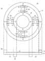
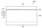
ところで、従来、力覚センサから出力される電気信号を外部に取り出すためのコネクタが力覚センサの外装体(筐体)に設けられている。図12および図13を参照して従来の力覚センサについて説明する。なお、図13では、コネクタ固定体370の上面は透視して図示している。 By the way, conventionally, a connector for taking out an electric signal output from a force sensor to the outside is provided on the outer body (housing) of the force sensor. A conventional force sensor will be described with reference to FIGS. 12 and 13. In FIG. 13, the upper surface of the
図12および図13に示すように、従来の力覚センサ300は、ロボットのエンドエフェクタ等から力またはモーメントの作用を受ける受力体310と、この受力体310および検出リング(図示せず)を支持する支持体330と、電気信号を出力する検出回路(図示せず)に電気的に接続されたコネクタ350と、円柱状の外装体360と、コネクタ固定体370と、を備えている。受力体310と外装体360の間には、防水・防塵用の弾性体361が設けられている。 As shown in FIGS. 12 and 13, the
コネクタ固定体370は、外装体360の外周面に設けられ、コネクタ350を固定している。コネクタ350は、レセプタクル(メス型コネクタ)であり、ロボットの制御部と電気ケーブルを介して接続される。図12および図13に示すように、コネクタ350は、外装体360の周方向に沿って電気ケーブルを接続する。なお、図示しないが、外装体360の半径方向に沿って電気ケーブルを接続するコネクタもある。 The
上記のように、従来の力覚センサ300では、コネクタ固定体370が外装体360の外周面に設けられる。電気ケーブルは、力覚センサとロボットの間を架け渡したり、ロボットの外装を這うように配線されて、外装体360の外周面側からコネクタ350に接続される。このため、従来の力覚センサでは、ロボットの動作に伴って電気ケーブルが破損ないし破断するおそれが高まるという課題があった。また、電気ケーブルがロボットの外部に露出しているため、作業者、被支援者等の人が電気ケーブルに引っかかるなどの安全性の問題や、見栄えが損なわれるという課題もある。 As described above, in the
本発明は、上記の技術的認識に基づいてなされたものであり、その目的は、ロボットの安全性および信頼性を向上させるとともに、ロボットの見栄えを向上させることができる力覚センサを提供することである。 The present invention has been made based on the above technical recognition, and an object of the present invention is to provide a force sensor capable of improving the safety and reliability of a robot and improving the appearance of the robot. Is.
本発明に係る力覚センサは、
ロボットに装着される力覚センサであって、
検出対象となる力またはモーメントの作用を受ける受力体と、
前記受力体が受けた力またはモーメントを検出する検出部を有する検出リングと、
前記検出リングを支持する支持体と、
前記検出部の検出結果に基づいて、前記検出リングに作用した力またはモーメントを示す電気信号を出力する検出回路と、
一方の開口部に前記受力体が配置され、他方の開口部に前記支持体が配置され、前記検出リングを内蔵する筒状の外装体と、
前記電気信号を出力する前記検出回路の端子に電気的に接続されたコネクタであって、前記ロボットの内部に延設された電気ケーブルを前記支持体側から接続可能に設けられたコネクタと、を備える。The force sensor according to the present invention is
A force sensor attached to a robot
A receiving body that is affected by the force or moment to be detected,
A detection ring having a detection unit for detecting the force or moment received by the receiving body, and
A support that supports the detection ring and
A detection circuit that outputs an electric signal indicating a force or moment acting on the detection ring based on the detection result of the detection unit, and a detection circuit.
A tubular exterior body in which the receiving body is arranged in one opening, the support is arranged in the other opening, and the detection ring is built in, and
It is provided with a connector electrically connected to the terminal of the detection circuit that outputs the electric signal, and is provided so that an electric cable extending inside the robot can be connected from the support side. ..
また、前記力覚センサにおいて、
前記支持体は、前記受力体と対向する第1の主面と、前記第1の主面と反対側の第2の主面とを有し、
前記第2の主面には凹部が設けられ、
前記コネクタは、前記凹部の底部に設けられた貫通孔に嵌合してもよい。Further, in the force sensor,
The support has a first main surface facing the receiving body and a second main surface opposite to the first main surface.
A recess is provided on the second main surface.
The connector may be fitted into a through hole provided at the bottom of the recess.
また、前記力覚センサにおいて、
前記コネクタは、前記第2の主面側に露出する接続面を有しており、前記接続面が前記第2の主面よりも奥側に位置するように前記支持体に固定されていてもよい。Further, in the force sensor,
The connector has a connecting surface exposed to the second main surface side, and even if the connecting surface is fixed to the support so as to be located on the back side of the second main surface. good.
また、前記力覚センサにおいて、
前記支持体は、前記受力体と対向する第1の主面と、前記第1の主面と反対側の第2の主面とを有し、
前記第1の主面と前記の第2の主面間を貫通する貫通孔が設けられ、
前記第1の主面側における前記貫通孔の開口を覆うとともに、前記コネクタを固定するコネクタ固定体をさらに備えてもよい。Further, in the force sensor,
The support has a first main surface facing the receiving body and a second main surface opposite to the first main surface.
A through hole is provided so as to penetrate between the first main surface and the second main surface.
A connector fixing body for fixing the connector may be further provided while covering the opening of the through hole on the first main surface side.
また、前記力覚センサにおいて、
前記コネクタは、前記第2の主面側に露出する接続面を有しており、前記接続面が前記第2の主面よりも奥側に位置するように前記コネクタ固定体に固定されていてもよい。Further, in the force sensor,
The connector has a connecting surface exposed to the second main surface side, and is fixed to the connector fixing body so that the connecting surface is located on the back side of the second main surface. May be good.
また、前記力覚センサにおいて、
前記支持体は、前記受力体と対向する第1の主面と、前記第1の主面と反対側の第2の主面とを有し、
前記コネクタは、前記支持体に設けられた貫通孔に嵌合し、
前記第2の主面から突出した前記コネクタを囲うように突設されたコネクタ保護体をさらに備えてもよい。Further, in the force sensor,
The support has a first main surface facing the receiving body and a second main surface opposite to the first main surface.
The connector is fitted into a through hole provided in the support.
A connector protector projecting so as to surround the connector protruding from the second main surface may be further provided.
また、前記力覚センサにおいて、
前記支持体が環状であり、前記外装体の内周面が前記支持体の外周側面に接続しており、
外周面が前記支持体の内周側面に接続する筒状の内装体をさらに備え、前記コネクタのうち少なくとも一部は前記内装体の内部に配置されていてもよい。Further, in the force sensor,
The support is annular, and the inner peripheral surface of the exterior body is connected to the outer peripheral side surface of the support.
A tubular interior body whose outer peripheral surface connects to the inner peripheral side surface of the support may be further provided, and at least a part of the connectors may be arranged inside the interior body.
また、前記力覚センサにおいて、
前記内装体の内周面に設けられ、前記コネクタを固定するコネクタ固定体をさらに備えてもよい。Further, in the force sensor,
A connector fixing body provided on the inner peripheral surface of the interior body and fixing the connector may be further provided.
また、前記力覚センサにおいて、
前記コネクタ固定体は、
前記コネクタを固定する固定板部と、
前記固定板部および前記内装体の内周面に接続し、前記コネクタのうち前記 固定板部より上方の部分を取り囲むカバー部と、
を有してもよい。Further, in the force sensor,
The connector fixing body is
A fixing plate for fixing the connector and
A cover portion that is connected to the fixed plate portion and the inner peripheral surface of the interior body and surrounds a portion of the connector above the fixed plate portion.
May have.
また、前記力覚センサにおいて、
前記コネクタは、L字状に構成されており、前記内装体に設けられた貫通孔に嵌合されていてもよい。Further, in the force sensor,
The connector has an L-shape and may be fitted into a through hole provided in the interior body.
また、前記力覚センサにおいて、
前記内装体には、前記電気ケーブル以外のケーブルを挿通可能な配線スペースが確保されていてもよい。Further, in the force sensor,
A wiring space into which a cable other than the electric cable can be inserted may be secured in the interior body.
また、前記力覚センサにおいて、
前記コネクタは、前記第2の主面側に露出する接続面が前記第2の主面よりも奥側に位置するように前記内装体の内部に配置されていてもよい。Further, in the force sensor,
The connector may be arranged inside the interior body so that the connection surface exposed to the second main surface side is located on the back side of the second main surface.
また、前記力覚センサにおいて、
前記コネクタを固定するとともに、前記支持体側から前記外装体または前記支持体に取り付けられたコネクタ固定外装体をさらに備えてもよい。Further, in the force sensor,
In addition to fixing the connector, the exterior body or the connector fixing exterior body attached to the support may be further provided from the support side.
また、前記力覚センサにおいて、
前記コネクタ固定外装体は、筒部と、前記筒部の下端を閉塞する底部と、前記底部に設けられた貫通孔を覆うように設けられ、前記コネクタを固定するコネクタ固定部とを有してもよい。Further, in the force sensor,
The connector fixing exterior body has a tubular portion, a bottom portion that closes the lower end of the tubular portion, and a connector fixing portion that is provided so as to cover a through hole provided in the bottom portion and fixes the connector. May be good.
また、前記力覚センサにおいて、
前記底部は、前記支持体と対向する第1の主面と、前記第1の主面と反対側の第2の主面とを有し、
前記コネクタは、前記第2の主面側に露出する接続面が前記第2の主面よりも奥側に位置するように前記コネクタ固定部に固定されていてもよい。Further, in the force sensor,
The bottom portion has a first main surface facing the support and a second main surface opposite to the first main surface.
The connector may be fixed to the connector fixing portion so that the connection surface exposed to the second main surface side is located on the back side of the second main surface.
また、前記力覚センサにおいて、
前記コネクタは、前記検出リングの中心軸に沿って設けられていてもよい。Further, in the force sensor,
The connector may be provided along the central axis of the detection ring.
また、前記力覚センサにおいて、
前記検出部は、前記検出リングの中心点から見て均等に分散して複数設けられていてもよい。Further, in the force sensor,
A plurality of the detection units may be provided evenly dispersed when viewed from the center point of the detection ring.
本発明に係る力覚センサでは、電気信号を出力する検出回路の端子に電気的に接続されたコネクタが、ロボットの内部に延設された電気ケーブルを支持体側から接続可能に設けられている。これにより、従来のように電気ケーブルをロボットの外部に設けるのではなく、ロボットの内部に設けることができるようになる。その結果、作業者、被支援者等の人が電気ケーブルに引っかかるなどの事態を防止することができる。また、ロボットの動作時に電気ケーブルが破損ないし破断することを抑制することができる。さらに、電気ケーブルが外側から見えないため、ロボットの見栄えを向上させることができる。よって、本発明によれば、ロボットの安全性および信頼性を向上させるとともに、ロボットの見栄えを向上させることができる。 In the force sensor according to the present invention, a connector electrically connected to a terminal of a detection circuit that outputs an electric signal is provided so that an electric cable extending inside the robot can be connected from the support side. As a result, the electric cable can be provided inside the robot instead of being provided outside the robot as in the conventional case. As a result, it is possible to prevent a situation in which a worker, a person to be supported, or the like is caught in the electric cable. In addition, it is possible to prevent the electric cable from being damaged or broken during the operation of the robot. Furthermore, since the electric cable cannot be seen from the outside, the appearance of the robot can be improved. Therefore, according to the present invention, the safety and reliability of the robot can be improved, and the appearance of the robot can be improved.
以下、本発明に係る実施形態について図面を参照しながら説明する。なお、各図においては、同等の機能を有する構成要素に同一の符号を付している。また、図面は模式的なものであり、厚みと平面寸法との関係等は現実のものとは異なる。 Hereinafter, embodiments according to the present invention will be described with reference to the drawings. In each figure, the same reference numerals are given to the components having the same functions. In addition, the drawings are schematic, and the relationship between the thickness and the plane dimensions is different from the actual one.
<力覚センサのロボットへの適用>
実施形態に係る力覚センサについて説明する前に、当該力覚センサのロボットへの適用例について図1を参照して説明する。<Application of force sensor to robots>
Before explaining the force sensor according to the embodiment, an example of application of the force sensor to a robot will be described with reference to FIG.
図1に示すように、産業用ロボット1000は、ロボット本体1100と、エンドエフェクタ1200と、電気ケーブル1300と、制御部1400と、力覚センサ1と、を有している。ロボット本体1100は、ロボットのアーム部を含んでいる。ロボット本体1100とエンドエフェクタ1200の間には、力覚センサ1が設けられている。 As shown in FIG. 1, the
電気ケーブル1300は、ロボット本体1100の内部に延設されている。この電気ケーブル1300は、力覚センサ1のコネクタ50(後述)に接続している。 The
なお、図1では、制御部1400はロボット本体1100の内部に配置されているが、他の場所(例えばロボット外部の制御盤)に配置されてもよい。また、力覚センサ1のロボットへの装着態様は図1に示すものに限られない。 Although the
力覚センサ1は、グリッパー等のエンドエフェクタ1200に作用する力またはモーメントを検出する。検出された力またはモーメントを示す電気信号は、電気ケーブル1300を介して産業用ロボット1000の制御部1400に送信される。制御部1400は、受信した電気信号に基づいてロボット本体1100およびエンドエフェクタ1200の動作を制御する。 The
実施形態に係る力覚センサ1を適用した産業用ロボット1000においては、電気ケーブル1300がロボット本体1100内に配置されている。このため、ロボット動作時に、電気ケーブル1300が外部の物体と接触等したり、電気ケーブル1300に張力や曲げ応力が加わることにより、破損ないし破断することが抑制される。 In the
なお、力覚センサ1は、産業用ロボットに限られず、生活支援ロボット、医療用ロボット等の各種ロボットに適用可能である。 The
以下、本発明の実施形態に係る力覚センサについて説明する。 Hereinafter, the force sensor according to the embodiment of the present invention will be described.
(第1の実施形態)
図2および図3を参照して、第1の実施形態に係る力覚センサについて説明する。図2は、本実施形態に係る力覚センサ1の一部縦断面図である。なお、図2では、接続部15、固定部16および検出リング20は模式的に示している。これらの構成要素の具体例は、図4および図5を参照して説明する。図3は、本実施形態に係る力覚センサ1の下面図である。(First Embodiment)
The force sensor according to the first embodiment will be described with reference to FIGS. 2 and 3. FIG. 2 is a partial vertical sectional view of the
力覚センサ1は、所定の軸方向に作用した力および所定の回転軸まわりに作用したモーメント(トルク)を電気信号として出力する機能を有する。本実施形態に係る力覚センサ1の外形は背の低い円柱状である。 The
力覚センサ1は、図2に示すように、受力体10と、接続部15と、固定部16と、検出リング20と、支持体30と、検出回路40と、コネクタ50と、筒状の外装体60とを備えている。以下、各構成要素について詳しく説明する。 As shown in FIG. 2, the
受力体10は、検出対象となる力またはモーメントの作用を受ける。作用を受けることにより、受力体10は支持体30に対して相対移動する。先に説明した図1の例で言えば、受力体10はエンドエフェクタ1200に接しており、エンドエフェクタ1200から力またはモーメントを受ける。 The receiving
本実施形態では、受力体10の形状は円盤状である。なお、受力体10の平面形状は、円形に限られず、方形、多角形、楕円形等の他の形状であってもよい。また、受力体10は、従来の力覚センサ300の受力体310のように、外装体60の開口端を上側から覆うように設けられてもよい。 In the present embodiment, the shape of the receiving
受力体10は、接続部15を介して検出リング20に接続されている。この受力体10は、図2に示すように、接続部15、検出リング20および固定部16を介して支持体30に支持されている。 The receiving
接続部15は、受力体10を、検出リング20の所定の部分に接続する。図4の例では、接続部15は受力体10を検出リング20の作用点Q1,Q2に接続する。また、図5の例では、接続部15は受力体10を検出リング20の外側リング部21に接続する。 The connecting
検出リング20は、受力体10が受けた力またはモーメントを検出する検出部D1〜D4を有する。検出部D1〜D4は、受力体10が受けた力またはモーメントを検出することによって歪みまたは変位を生じるように構成されている。検出部D1〜D4の構成例は図4、図5を参照して後ほど詳しく説明する。なお、接続部15、固定部16および検出リング20を総称して、起歪体と呼ぶこともある。 The
支持体30は、検出リング20を支持する。より詳しくは、支持体30は、固定部16を介して検出リング20を支持する。図1の例で言えば、支持体30はロボット本体1100(アーム部)の先端にネジで固定される。 The
固定部16は、検出リング20の所定の部分を支持体30に固定する。図4の例では、固定部16は検出リング20の固定点P1,P2を支持体30に固定する。また、図5の例では、固定部16は検出リング20の内側リング部22を支持体30に固定する。なお、図5の例において、接続部15が受力体10を内側リング部22に接続し、固定部16が外側リング部21を支持体30に固定してもよい。 The fixing
本実施形態では、支持体30の形状は円盤状である。なお、支持体30の平面形状は、円形に限られず、方形、多角形、楕円形等の他の形状であってもよい。 In the present embodiment, the shape of the
支持体30は、図2に示すように、受力体10と対向する主面30a(第1の主面)と、主面30aと反対側の主面30b(第2の主面)とを有する。図2および図3に示すように、支持体30の主面30bには、凹部31が設けられている。本実施形態では、凹部31は支持体30の中心に設けられている。これにより、コネクタ50を検出リング20の中央部分に配置することができ、力覚センサ1の内部空間を効率的に使用することができる。ただし、本発明は、凹部31を支持体30の中心から外れた位置に設けることを排除するものではない。 As shown in FIG. 2, the
検出回路40は、検出リング20の検出部D1〜D4の検出結果に基づいて、検出リング20に作用した力またはモーメントを示す電気信号を出力する。この検出回路40は、例えばマイクロプロセッサにより構成される。検出回路40は、検出部D1〜D4から受信したアナログ信号をデジタル信号に変換するA/D変換機能や、信号を増幅する機能を有してもよい。 The
コネクタ50は、検出リング20に作用した力またはモーメントを示す電気信号を出力する検出回路40の端子に電気的に接続されている。コネクタ50は、例えば、電気ケーブル1300のプラグ(オス型コネクタ)を接続可能なレセプタクル(メス型コネクタ)である。 The
コネクタ50は、図2および図3に示すように、複数の端子51と、複数のガイドピン挿入孔52とを有する。端子51は、配線コードを介して検出回路40の出力端子に電気的に接続されている。なお、図1では、端子51を2つしか図示していないが、実際にはコネクタ50はガイドピン挿入孔52の数に応じた端子51を有する。 As shown in FIGS. 2 and 3, the
コネクタ50は、図2に示すように、支持体30の主面30b側に露出する接続面50aを有する。この接続面50aに複数のガイドピン挿入孔52が設けられている。 As shown in FIG. 2, the
コネクタ50は、図1を参照して説明したように、ロボットの内部に延設された電気ケーブルを支持体30側から接続可能に設けられている。本実施形態では、コネクタ50は、図2に示すように、凹部31の底部に設けられた貫通孔に嵌合している。 As described with reference to FIG. 1, the
コネクタ50は、図2に示すように、検出リング20の中心軸に沿って主面30a,30bと直交するように設けられている。ただし、本発明はこれに限られない。すなわち、コネクタ50が支持体30側から電気ケーブル1300を接続可能であれば、コネクタ50は中心軸から外れて設けられてもよいし、支持体30と斜交するように設けられてもよい。 As shown in FIG. 2, the
なお、接続面50aは支持体30の主面30a,30bと平行でなくてもよい。 The connecting
本願発明において、「電気ケーブルを支持体側から接続可能」であるとは、支持体側から力覚センサに接近する電気ケーブルを接続可能であることを意味するものであって、支持体30の主面30a,30bと平行な面で電気ケーブルと接続する必要は必ずしもない。 In the present invention, "the electric cable can be connected from the support side" means that the electric cable approaching the force sensor can be connected from the support side, and the main surface of the
コネクタ50の種類は特に限定されるものではなく、例えば、RS−422、USB等の規格に準拠したものが適用される。なお、コネクタ50はプラグであってもよい。この場合、端部にレセプタクルが設けられた電気ケーブル1300とコネクタ50が接続される。 The type of the
図2に示すように、コネクタ50は、接続面50aが主面30bよりも奥側に位置するように支持体30に固定されていてもよい。図2では、接続面50aは支持体30の主面30aよりも長さdだけ奥側に位置している。これにより、支持体30が他の物体に衝突した場合にコネクタ50が破損することを防止できる。本実施形態では凹部31の底部でコネクタ50を固定するため、接続面50aが主面30bよりも奥側に位置するようにコネクタ50の位置調整を容易に行うことができる。 As shown in FIG. 2, the
コネクタ50は、支持体30に凹部31を設けず、支持体30に設けられた貫通孔に嵌合するように支持体30に固定されてもよい。 The
外装体60は、力覚センサ1の筒状の筐体である。本実施形態では外装体60の横断面形状は円形であるが、これに限られず、方形、多角形、楕円形等、他の形状であってもよい。 The
外装体60の一方の開口部(図2では上側の開口部)に受力体10が配置され、他方の開口部(図2では下側の開口部)に支持体30が配置されている。検出リング20は、外装体60に内蔵されている。 The receiving
より詳しくは、図2に示すように、支持体30は外装体60の下側の開口部を閉塞するように外装体60に固定されている。一方、受力体10と外装体60との間には隙間が設けられており、受力体10は、ロボットから受けた力またはモーメントに応じて動くことが可能である。なお、防水性や防塵性を確保するために、受力体10と外装体60との間の隙間にゴム等の弾性材が介装されてもよい。また、外装体60は、支持体30と一体的に構成されたものであってもよい。 More specifically, as shown in FIG. 2, the
上記のように、第1の実施形態に係る力覚センサ1では、コネクタ50が凹部31の底部に設けられた貫通孔に嵌合しており、電気信号を送信するための電気ケーブルを支持体30側から接続することが可能である。これにより、従来のように電気ケーブルをロボットの外部に設けるのではなく、ロボットの内部に設けることができるようになる。その結果、作業者、被支援者等の人が電気ケーブルに引っかかるなどの事態を防止することができる。また、ロボットの動作時に電気ケーブルが破損ないし破断することを抑制することができる。よって、ロボットの安全性および信頼性を向上させることができる。さらに、電気ケーブルが外側から見えないため、ロボットの見栄えを向上させることができる。 As described above, in the
以上説明したように、第1の実施形態によれば、ロボットの安全性および信頼性を向上させるとともに、ロボットの見栄えを向上させることができる。 As described above, according to the first embodiment, the safety and reliability of the robot can be improved, and the appearance of the robot can be improved.
<検出リングの例>
ここで、図4(a)〜(c)、図5(a),(b)を参照して検出リング20の具体例について説明する。図4は静電容量型の検出リングであり、図5は歪みゲージ型の検出リングである。なお、図5では、検出リング20に加えて、接続部15および固定部16も図示している。<Example of detection ring>
Here, a specific example of the
まず、静電容量型の検出リングについて説明する。図4(a)〜(c)に示す検出リング20は、弾性変形する板状片を組み合わせて構成された検出部D1〜D4が円環状の構造体の4箇所に設けられている。より詳しくは、検出部D1〜D4は、円環状の検出リング20の中心点(原点O)から見て均等に分散して設けられている。検出リング20は、4組の検出部D1〜D4と、これら検出部D1〜D4を相互に連結する4組の連結部L1〜L4と、を有している。なお、検出部の数は4つに限られるものではない。 First, a capacitance type detection ring will be described. In the detection rings 20 shown in FIGS. 4A to 4C, detection portions D1 to D4 formed by combining elastically deformable plate-shaped pieces are provided at four positions in an annular structure. More specifically, the detection units D1 to D4 are provided so as to be evenly dispersed when viewed from the center point (origin O) of the
図4(b)に示すように、検出部D1〜D4の各々は、変形部26、変形部27、変位部28という3枚の板状片(板バネ)によって構成されている。板状片は、連結部L1〜L4に比べて肉厚が薄い。したがって、検出部D1〜D4は、連結部L1〜L4に比べて弾性変形しやすい。このため、検出リング20に外力が作用した場合、当該外力に基づく検出リング20の弾性変形は、検出部D1〜D4に集中して生じ、連結部L1〜L4の弾性変形は、実用上、無視し得る程度である。 As shown in FIG. 4B, each of the detection units D1 to D4 is composed of three plate-shaped pieces (leaf springs), which are a deformed part 26, a
検出部D1〜D4およびこれに対向する支持体30の所定部分に電極(図示せず)が設けられる。このように設けられた電極間の静電容量は、変位部28の変位により変化する。この静電容量の変化に基づいて、受力体10ないし検出リング20に作用した外力の向きおよび大きさを検出することが可能である。 Electrodes (not shown) are provided at predetermined portions of the detection units D1 to D4 and the
次に、歪みゲージ型の検出リングについて説明する。図5(a),(b)に示す検出リング20は、外側リング部21と、この外側リング部21と同心円の内側リング部22と、複数本の梁部23と、複数個の歪みゲージ25とを有する。図5(b)に示すように、外側リング部21には円環状の接続部15が設けられている。この接続部15は受力体10に固定されている。また、内側リング部22には円環状の固定部16が設けられている。この固定部16は支持体30に固定されている。 Next, a strain gauge type detection ring will be described. The
外側リング部21と内側リング部22は、4本の梁部23で接続されている。各梁部23には、6個の歪みゲージ25が設けられている。より詳しくは、梁部23の両側面にそれぞれ2個の歪みゲージ25が設けられ、梁部23の上面にも2個の歪みゲージ25が設けられる。図5(a)に示すように、歪みゲージ25は、梁部23の両端部(すなわち、外側リング部21と梁部23との接続部分、および内側リング部22と梁部23との接続部分)に設けられる。検出部D1〜D4は、円環状の検出リング20の中心点から見て均等に分散して設けられている。なお、梁部23の数は4本に限られるものではない。 The outer ring portion 21 and the
上記歪みゲージ型の検出リング20は、4本の梁部23に設けられた合計24個の歪みゲージ25により、受力体10に作用した力とモーメントを検出することが可能である。 The strain gauge
(第2の実施形態)
次に、図6を参照して、第2の実施形態に係る力覚センサについて説明する。図6は、本実施形態に係る力覚センサ1Aの一部縦断面図である。なお、図6では、接続部15、固定部16および検出リング20は模式的に示している。(Second embodiment)
Next, the force sensor according to the second embodiment will be described with reference to FIG. FIG. 6 is a partial vertical sectional view of the
第2の実施形態では、コネクタ50が支持体30Aではなく、コネクタ固定体70により固定される。以下、第1の実施形態との相違点を中心に、第2の実施形態に係る力覚センサ1Aについて説明する。 In the second embodiment, the
力覚センサ1Aは、図6に示すように、受力体10と、接続部15と、固定部16と、検出リング20と、支持体30Aと、検出回路40と、コネクタ50と、外装体60と、コネクタ固定体70と、を備えている。 As shown in FIG. 6, the
支持体30Aは、受力体10と対向する主面30aと、主面30aと反対側の主面30bとを有する。本実施形態では、図6に示すように、支持体30Aの主面30aと主面30b間を貫通する貫通孔32が設けられている。この貫通孔32にコネクタ50が挿通されている。 The
力覚センサ1Aは、コネクタ固定体70をさらに備えている。このコネクタ固定体70は、主面30a側における貫通孔32の開口を覆うとともに、コネクタ50を固定する。コネクタ固定体70は、ネジや接着剤等により支持体30Aに固定されていてもよいし、あるいは、支持体30Aと一体的に形成されたものであってもよい。 The
なお、コネクタ50は、図6に示すように、接続面50aが主面30bよりも奥側に位置するようにコネクタ固定体70に固定されていてもよい。これにより、支持体30Aが他の物体に衝突した場合にコネクタ50が破損することを防止できる。本実施形態ではコネクタ固定体70でコネクタ50を固定するため、接続面50aが主面30bよりも奥側に位置するようにコネクタ50の位置調整を容易に行うことができる。 As shown in FIG. 6, the
上記のように、第2の実施形態に係る力覚センサ1Aでは、コネクタ50が支持体30Aの貫通孔32に挿通され、コネクタ固定体70に固定されている。このため、電気信号を送信するための電気ケーブルを支持体30A側から接続することが可能である。よって、第2の実施形態によれば、第1の実施形態と同様に、ロボットの安全性および信頼性を向上させることができるとともに、ロボットの見栄えを向上させることができる。 As described above, in the
さらに、第2の実施形態では、コネクタ固定体70によりコネクタ50を支持固定するため、第1の実施形態の支持体30に比べて支持体30Aを薄くすることができる。その結果、第2の実施形態によれば、力覚センサの軽量化を図ることができる。 Further, in the second embodiment, since the
(第3の実施形態)
次に、図7を参照して、第3の実施形態に係る力覚センサについて説明する。図7は、本実施形態に係る力覚センサ1Bの一部縦断面図である。なお、図7では、接続部15、固定部16および検出リング20は模式的に示している。(Third Embodiment)
Next, the force sensor according to the third embodiment will be described with reference to FIG. 7. FIG. 7 is a partial vertical sectional view of the
第3の実施形態では、コネクタ50が支持体30Bに固定され、支持体30Bから外部に突出した部分がコネクタ保護体80により保護される。以下、第1の実施形態との相違点を中心に、第3の実施形態に係る力覚センサ1Bについて説明する。 In the third embodiment, the
力覚センサ1Bは、図7に示すように、受力体10と、接続部15と、固定部16と、検出リング20と、支持体30Bと、検出回路40と、コネクタ50と、外装体60と、コネクタ50を保護するためのコネクタ保護体80と、を備えている。 As shown in FIG. 7, the
本実施形態では、図7に示すように、コネクタ50は、支持体30Bに設けられた貫通孔に嵌合し、固定されている。支持体30Bは、受力体10と対向する主面30aと、主面30aと反対側の主面30bとを有する。 In the present embodiment, as shown in FIG. 7, the
コネクタ保護体80は、支持体30Bの主面30bから突出したコネクタ50を囲うように突設されている。コネクタ保護体80は、ネジや接着剤等により支持体30Bに固定されていてもよいし、あるいは、支持体30Bと一体的に形成されたものであってもよい。 The connector
なお、コネクタ保護体80は、コネクタ50を連続的に囲ってもよいし、あるいは、コネクタ50の周りに設けた複数の突起によりコネクタ50を非連続的に囲ってもよい。 The
また、コネクタ保護体80は、図7に示すように、支持体30Bの主面30bから、コネクタ50の突出部分よりも高く突設されてもよい。これにより、より確実にコネクタ50を保護することができる。 Further, as shown in FIG. 7, the connector
上記のように、第3の実施形態に係る力覚センサ1Bでは、コネクタ50が支持体30Bに設けられた貫通孔に嵌合しているとともに、コネクタ保護体80で保護されている。このため、電気信号を送信するための電気ケーブルを支持体30側から接続することが可能である。よって、第3の実施形態によれば、第1の実施形態と同様に、ロボットの安全性および信頼性を向上させることができるとともに、ロボットの見栄えを向上させることができる。 As described above, in the
さらに、第3の実施形態によれば、コネクタ50が主面30b側に突出する分、コネクタ50の、主面30aからの突出量を低減することができるため、受力体10と支持体30B間の距離を短くすることができる。その結果、力覚センサの薄型化を図ることができる。 Further, according to the third embodiment, the amount of protrusion of the
(第4の実施形態)
次に、図8および図9を参照して、第4の実施形態に係る力覚センサについて説明する。図8は、本実施形態に係る力覚センサ1Cの一部縦断面図である。なお、図8では、接続部15、固定部16および検出リング20は模式的に示している。図9は、力覚センサ1Cの下面図である。(Fourth Embodiment)
Next, the force sensor according to the fourth embodiment will be described with reference to FIGS. 8 and 9. FIG. 8 is a partial vertical sectional view of the
第4の実施形態に係る力覚センサ1Cは筒状の内装体65を有し、この内装体65内にコネクタ50が設けられる。以下、第1の実施形態との相違点を中心に、第4の実施形態に係る力覚センサ1Cについて説明する。 The
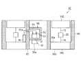
力覚センサ1Cは、図8に示すように、環状の受力体10Cと、接続部15と、固定部16と、検出リング20と、環状の支持体30Cと、検出回路40と、コネクタ50と、筒状の外装体60と、外装体60の内側に配置された筒状の内装体65と、コネクタ固定体90と、を備えている。コネクタ50のうち少なくとも一部は、内装体65の内部に配置されている。 As shown in FIG. 8, the
本実施形態の受力体10Cおよび支持体30Cは円環状の構造体である。なお、受力体10Cおよび支持体30Cは、矩形環状等、他の環状体であってもよい。支持体30Cは、受力体10Cと対向する主面30aと、主面30aと反対側の主面30bとを有する。 The receiving
図8および図9に示すように、外装体60の内周面が支持体30Cの外周側面に接続する。また、内装体65は、その外周面が支持体30Cの内周側面に接続する。内装体65の中心軸は外装体60の中心軸とほぼ一致する。 As shown in FIGS. 8 and 9, the inner peripheral surface of the
コネクタ固定体90は、内装体65の内周面に設けられ、コネクタ50を固定する。このコネクタ固定体90は、コネクタ50を固定する固定板部91と、固定板部91および内装体65の内周面に接続し、コネクタ50のうち固定板部91より上方の部分を取り囲むカバー部92,93と、を有する箱状のものとして構成されている。カバー部92,93を設けることで防水性や防塵性を向上させることができる。ただし、カバー部92,93は必須の構成ではなく、固定板部91のみを内装体65の内周面に設けてもよい。 The
本実施形態では、コネクタ50の端子51に接続された配線コードは、図8に示すように、内装体65の貫通孔を通って検出回路40に配線されている。 In the present embodiment, the wiring cord connected to the
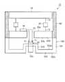
図9に示すように、内装体65の内部空間の一部はコネクタ固定体90により占められるものの、電気ケーブル1300以外の各種ケーブル(電気ケーブル、圧力ケーブル等)を挿通可能な配線スペースSが確保されている。これにより、ロボット本体1100とエンドエフェクタ1200間の電気ケーブル等を、力覚センサ1C内を通して配線することができるようになる。その結果、ロボットの安全性、信頼性および見栄えをさらに向上させることができる。 As shown in FIG. 9, although a part of the internal space of the
なお、図9に示すように、コネクタ50は、接続面50aが支持体30Cの主面30bよりも奥側に位置するようにコネクタ固定体90により固定されていてもよい。コネクタ50は、すべて内装体65の内部に配置される。これにより、支持体30Cが他の物体に衝突した場合にコネクタ50が破損することを防止できる。 As shown in FIG. 9, the
上記のように、第4の実施形態に係る力覚センサ1Cでは、コネクタ50が内装体65の内部にコネクタ固定体90により固定されている。このため、電気信号を送信するための電気ケーブルを支持体30側から接続することが可能である。よって、第4の実施形態によれば、第1の実施形態と同様に、ロボットの安全性および信頼性を向上させることができるとともに、ロボットの見栄えを向上させることができる。 As described above, in the
なお、本実施形態の変形例として、環状の受力体10Cに代えて、円盤状等、貫通孔を有しない受力体10を備える力覚センサを想定することも可能である。この場合、内装体65は、支持体30C側から、受力体10よりも下の位置まで延在する。 As a modification of the present embodiment, it is also possible to assume a force sensor having a disc-shaped receiving
本実施形態の別の変形例として、図10に示すように、コネクタ50がL字型に構成されている。そして、L字型のコネクタ50が内装体65に設けられた貫通孔に嵌合されている。より具体的には、コネクタ50は、接続面50aが支持体30Cの主面30a,30bと略平行になるように内装体65に直接固定されている。本変形例によっても、第4の実施形態と同様の効果を得ることができる。 As another modification of this embodiment, as shown in FIG. 10, the
なお、上記の変形例において、コネクタ50は、接続面50aが支持体30Cの主面30bよりも奥側に位置するように内装体65により固定されていてもよい。また、内装体65には、電気ケーブル以外のケーブルを挿通可能な配線スペースが確保されていてもよい。 In the above modification, the
(第5の実施形態)
次に、図11を参照して、第5の実施形態に係る力覚センサについて説明する。図11は、本実施形態に係る力覚センサ1Eの一部縦断面図である。なお、図11では、接続部15、固定部16および検出リング20は模式的に示している。(Fifth Embodiment)
Next, the force sensor according to the fifth embodiment will be described with reference to FIG. FIG. 11 is a partial vertical sectional view of the
第5の実施形態に係る力覚センサ1Eは、コネクタを固定する外付けのコネクタ固定外装体100を備える。以下、第1の実施形態との相違点を中心に、第5の実施形態に係る力覚センサ1Eについて説明する。 The
力覚センサ1Eは、図11に示すように、受力体10と、接続部15と、固定部16と、検出リング20と、支持体30Dと、検出回路40と、コネクタ50と、外装体60と、コネクタ固定外装体100と、を備えている。 As shown in FIG. 11, the
支持体30Dは、受力体10と対向する主面30aと、主面30aと反対側の主面30bとを有する。支持体30Dには、貫通孔33が設けられている。この貫通孔33には、検出回路40とコネクタ50を接続する配線コードが通されている。 The
コネクタ固定外装体100は、コネクタ50を固定するとともに、支持体30D側から外装体60に取り付けられている。例えば、コネクタ固定外装体100は、外装体60にネジで取り付けられる。その他、コネクタ固定外装体100は、接着剤、テープ等で外装体60に固定されてもよい。なお、コネクタ固定外装体100は支持体30Dに取り付けられてもよい。 The connector fixing
コネクタ固定外装体100は、筒部101と、この筒部101の下端を閉塞する底部102と、コネクタ固定部103とを有している。コネクタ固定外装体100は、筒部101の上端で外装体60に接続している。 The connector fixing
底部102は、支持体30Dと対向する主面102aと、主面102aと反対側の主面102bとを有する。 The
コネクタ固定部103は、底部102に設けられた貫通孔を覆うように設けられている。このコネクタ固定部103により、コネクタ50が固定されている。 The
なお、コネクタ50は、図11に示すように、底部102の主面102b側に露出する接続面50aが主面102bよりも奥側に位置するようにコネクタ固定部103に固定されていてもよい。これにより、コネクタ固定外装体100が他の物体に衝突した場合にコネクタ50が破損することを防止できる。 As shown in FIG. 11, the
本実施形態の変形例として、コネクタ固定外装体100にコネクタ固定部103を設けず、コネクタ50は、コネクタ固定外装体100の底部102に設けられた貫通孔に嵌合され固定されてもよい。あるいは、コネクタ50は、第1の実施形態のように、底部102に設けられた凹部の底面に貫設されてもよい。 As a modification of the present embodiment, the
上記のように、第5の実施形態に係る力覚センサ1Eでは、コネクタ50がコネクタ固定外装体100により固定されている。このため、電気信号を送信するための電気ケーブルを支持体30側から接続することが可能である。よって、第5の実施形態によれば、第1の実施形態と同様に、ロボットの安全性および信頼性を向上させることができるとともに、ロボットの見栄えを向上させることができる。 As described above, in the
上記の記載に基づいて、当業者であれば、本発明の追加の効果や種々の変形を想到できるかもしれないが、本発明の態様は、上述した個々の実施形態に限定されるものではない。異なる実施形態にわたる構成要素を適宜組み合わせてもよい。特許請求の範囲に規定された内容及びその均等物から導き出される本発明の概念的な思想と趣旨を逸脱しない範囲で種々の追加、変更及び部分的削除が可能である。 Based on the above description, those skilled in the art may be able to conceive of additional effects and various modifications of the present invention, but aspects of the present invention are not limited to the individual embodiments described above. .. Components across different embodiments may be combined as appropriate. Various additions, changes and partial deletions are possible without departing from the conceptual idea and purpose of the present invention derived from the contents defined in the claims and their equivalents.
1,1A,1B,1C,1D,1E,300 力覚センサ
10,310 受力体
15 接続部
16 固定部
20 検出リング
21 外側リング部
22 内側リング部
23 梁部
25 歪みゲージ
26,27 変形部
28 変位部
30,30A,30B,30C,30D,330 支持体
31 凹部
32,33 貫通孔
40 検出回路
50,350 コネクタ
50a 接続面
51 端子
52 ガイドピン挿入孔
60,360 外装体
65 内装体
65a 貫通孔
70,370 コネクタ固定体
80 コネクタ保護体
90 コネクタ固定体
91 固定板部
92,93 カバー部
100 コネクタ固定外装体
101 筒部
102 底部
103 コネクタ固定部
1000 産業用ロボット
1100 ロボット本体
1200 エンドエフェクタ
1300 電気ケーブル
1400 制御部
D1〜D4 検出部
L1〜L4 連結部
P1,P2 固定点
Q1,Q2 作用点
S 配線スペース1,1A, 1B, 1C, 1D, 1E, 300 Force sensor 10,310
Claims (1)
Translated fromJapanese検出対象となる力またはモーメントの作用を受ける受力体と、
前記受力体が受けた力またはモーメントを検出する検出部と、
前記検出部を支持する支持体と、
前記検出部から出力された信号を受信する検出回路と、
前記検出回路の端子に電気的に接続されたコネクタであって、前記ロボットの内部に延設された電気ケーブルを前記支持体側から接続可能に設けられたコネクタと、
を備え、
前記検出部は、接続部を介して前記受力体に接続され、且つ固定部を介して前記支持体に接続され、
前記支持体は前記受力体と対向する第1の主面と、前記第1の主面と反対側の第2の主面とを有し、
前記第2の主面には凹部が設けられ、
前記コネクタは、前記凹部の底部に設けられた貫通孔に嵌合している、力覚センサ。A force sensor attached to a robot
A receiving body that is affected by the force or moment to be detected,
A detection unit that detects the force or moment received by the receiving body,
A support that supports the detection unit and
A detection circuit that receives the signal output from the detection unit, and
A connector that is electrically connected to the terminal of the detection circuit and is provided so that an electric cable extending inside the robot can be connected from the support side.
With
The detection unit is connected to the receiving body via a connecting portion and is connected to the support via a fixing portion.
The support has a first main surface facing the receiving body and a second main surface opposite to the first main surface.
A recess is provided on the second main surface.
The connector is a force sensorfitted in a through hole provided at the bottom of the recess.
Priority Applications (4)
| Application Number | Priority Date | Filing Date | Title |
|---|---|---|---|
| JP2019023824AJP6918368B2 (en) | 2018-12-18 | 2019-02-13 | Force sensor |
| JP2021104407AJP6941402B1 (en) | 2019-02-13 | 2021-06-23 | Force sensor |
| JP2021138383AJP6961283B1 (en) | 2019-02-13 | 2021-08-26 | Force sensor |
| JP2021164165AJP7004368B2 (en) | 2019-02-13 | 2021-10-05 | Force sensor |
Applications Claiming Priority (2)
| Application Number | Priority Date | Filing Date | Title |
|---|---|---|---|
| JP2018236456AJP6488057B1 (en) | 2018-12-18 | 2018-12-18 | Force sensor |
| JP2019023824AJP6918368B2 (en) | 2018-12-18 | 2019-02-13 | Force sensor |
Related Parent Applications (1)
| Application Number | Title | Priority Date | Filing Date |
|---|---|---|---|
| JP2018236456ADivisionJP6488057B1 (en) | 2018-12-18 | 2018-12-18 | Force sensor |
Related Child Applications (1)
| Application Number | Title | Priority Date | Filing Date |
|---|---|---|---|
| JP2021104407ADivisionJP6941402B1 (en) | 2019-02-13 | 2021-06-23 | Force sensor |
Publications (3)
| Publication Number | Publication Date |
|---|---|
| JP2020056770A JP2020056770A (en) | 2020-04-09 |
| JP2020056770A5 JP2020056770A5 (en) | 2021-07-26 |
| JP6918368B2true JP6918368B2 (en) | 2021-08-11 |
Family
ID=70107110
Family Applications (1)
| Application Number | Title | Priority Date | Filing Date |
|---|---|---|---|
| JP2019023824AActiveJP6918368B2 (en) | 2018-12-18 | 2019-02-13 | Force sensor |
Country Status (1)
| Country | Link |
|---|---|
| JP (1) | JP6918368B2 (en) |
Families Citing this family (1)
| Publication number | Priority date | Publication date | Assignee | Title |
|---|---|---|---|---|
| JP6941402B1 (en)* | 2019-02-13 | 2021-09-29 | 株式会社トライフォース・マネジメント | Force sensor |
Family Cites Families (15)
| Publication number | Priority date | Publication date | Assignee | Title |
|---|---|---|---|---|
| US5490427A (en)* | 1994-10-17 | 1996-02-13 | Fanuc Usa Corporation | Six axis force sensor employing multiple shear strain gages |
| JP3883939B2 (en)* | 2002-09-04 | 2007-02-21 | ファナック株式会社 | Wiring processing structure of camera cable and force sensor cable in robot system |
| JP3929383B2 (en)* | 2002-10-15 | 2007-06-13 | ファナック株式会社 | Industrial robot camera and force sensor cable processing structure |
| JP2005014159A (en)* | 2003-06-26 | 2005-01-20 | Fanuc Ltd | Robot |
| JP2005144610A (en)* | 2003-11-17 | 2005-06-09 | Fanuc Ltd | Sensor cable wiring processing structure |
| JP4848700B2 (en)* | 2005-08-05 | 2011-12-28 | 株式会社安川電機 | Industrial robot |
| KR101477133B1 (en)* | 2006-06-13 | 2014-12-29 | 인튜어티브 서지컬 인코포레이티드 | Minimally invasive surgical system |
| US9144909B2 (en)* | 2007-07-05 | 2015-09-29 | Re2, Inc. | Defense related robotic systems |
| JP6168868B2 (en)* | 2012-06-29 | 2017-07-26 | キヤノン株式会社 | Force sensor and robot arm equipped with force sensor |
| EP2711142B1 (en)* | 2012-09-20 | 2014-09-17 | Comau S.p.A. | Industrial robot having electronic drive devices distributed on the robot structure |
| JP2015085449A (en)* | 2013-10-31 | 2015-05-07 | セイコーエプソン株式会社 | robot |
| JP6756166B2 (en)* | 2016-06-21 | 2020-09-16 | セイコーエプソン株式会社 | Force sensor unit and robot |
| JP6791483B2 (en)* | 2016-09-23 | 2020-11-25 | ニッタ株式会社 | Tool changer |
| JP6462946B1 (en)* | 2018-10-03 | 2019-01-30 | 株式会社トライフォース・マネジメント | Force sensor |
| JP6488057B1 (en)* | 2018-12-18 | 2019-03-20 | 株式会社トライフォース・マネジメント | Force sensor |
- 2019
- 2019-02-13JPJP2019023824Apatent/JP6918368B2/enactiveActive
Also Published As
| Publication number | Publication date |
|---|---|
| JP2020056770A (en) | 2020-04-09 |
Similar Documents
| Publication | Publication Date | Title |
|---|---|---|
| JP6462946B1 (en) | Force sensor | |
| JP6488057B1 (en) | Force sensor | |
| KR20140002507A (en) | Force sensor and robot arm including force sensor | |
| JP6363564B2 (en) | Small form factor pressure sensor | |
| JP6918368B2 (en) | Force sensor | |
| US20180252601A1 (en) | Force sensor | |
| US20180283965A1 (en) | Force Detection Device And Robot | |
| JP6941402B1 (en) | Force sensor | |
| JP6727605B1 (en) | Force sensor | |
| US20180372772A1 (en) | Acceleration measuring device and method for the production of an acceleration measuring device of said type | |
| JP5060909B2 (en) | Multi-axis photoelectric sensor | |
| CN115226401B (en) | Torque sensor | |
| US10323995B2 (en) | Rotation-shaft joint structure | |
| KR20230114257A (en) | Pressure sensor unit having temperature sensor | |
| KR102088119B1 (en) | Acceleration measuring device and manufacturing method of acceleration measuring device | |
| KR102012661B1 (en) | Torque sensor | |
| JP3769355B2 (en) | Explosion-proof load cell | |
| JP2011053423A (en) | Tuning device | |
| JP2020153729A (en) | Sensor and sensor fixing structure | |
| CN115552208A (en) | Force sensor device | |
| EP2366978A2 (en) | Cable leading-out structure | |
| JP2020197428A (en) | Vibration detector | |
| JP7308548B2 (en) | torque sensor | |
| US20250189555A1 (en) | Method of manufacturing a piezoelectric acceleration sensor and piezoelectric acceleration sensor obtained by this method | |
| KR102434356B1 (en) | Pressure sensor unit |
Legal Events
| Date | Code | Title | Description |
|---|---|---|---|
| A521 | Request for written amendment filed | Free format text:JAPANESE INTERMEDIATE CODE: A523 Effective date:20210510 | |
| A621 | Written request for application examination | Free format text:JAPANESE INTERMEDIATE CODE: A621 Effective date:20210510 | |
| A871 | Explanation of circumstances concerning accelerated examination | Free format text:JAPANESE INTERMEDIATE CODE: A871 Effective date:20210510 | |
| A131 | Notification of reasons for refusal | Free format text:JAPANESE INTERMEDIATE CODE: A131 Effective date:20210521 | |
| A521 | Request for written amendment filed | Free format text:JAPANESE INTERMEDIATE CODE: A523 Effective date:20210531 | |
| TRDD | Decision of grant or rejection written | ||
| A01 | Written decision to grant a patent or to grant a registration (utility model) | Free format text:JAPANESE INTERMEDIATE CODE: A01 Effective date:20210615 | |
| A61 | First payment of annual fees (during grant procedure) | Free format text:JAPANESE INTERMEDIATE CODE: A61 Effective date:20210714 | |
| R150 | Certificate of patent or registration of utility model | Ref document number:6918368 Country of ref document:JP Free format text:JAPANESE INTERMEDIATE CODE: R150 |