JP6916157B2 - Robot systems that collaborate with people and robot control methods - Google Patents
Robot systems that collaborate with people and robot control methodsDownload PDFInfo
- Publication number
- JP6916157B2 JP6916157B2JP2018199338AJP2018199338AJP6916157B2JP 6916157 B2JP6916157 B2JP 6916157B2JP 2018199338 AJP2018199338 AJP 2018199338AJP 2018199338 AJP2018199338 AJP 2018199338AJP 6916157 B2JP6916157 B2JP 6916157B2
- Authority
- JP
- Japan
- Prior art keywords
- robot
- work object
- detection device
- worker
- work
- Prior art date
- Legal status (The legal status is an assumption and is not a legal conclusion. Google has not performed a legal analysis and makes no representation as to the accuracy of the status listed.)
- Active
Links
Images


Classifications
- B—PERFORMING OPERATIONS; TRANSPORTING
- B25—HAND TOOLS; PORTABLE POWER-DRIVEN TOOLS; MANIPULATORS
- B25J—MANIPULATORS; CHAMBERS PROVIDED WITH MANIPULATION DEVICES
- B25J9/00—Programme-controlled manipulators
- B25J9/16—Programme controls
- B25J9/1694—Programme controls characterised by use of sensors other than normal servo-feedback from position, speed or acceleration sensors, perception control, multi-sensor controlled systems, sensor fusion
- B25J9/1697—Vision controlled systems
- B—PERFORMING OPERATIONS; TRANSPORTING
- B25—HAND TOOLS; PORTABLE POWER-DRIVEN TOOLS; MANIPULATORS
- B25J—MANIPULATORS; CHAMBERS PROVIDED WITH MANIPULATION DEVICES
- B25J9/00—Programme-controlled manipulators
- B25J9/16—Programme controls
- B25J9/1628—Programme controls characterised by the control loop
- B25J9/1633—Programme controls characterised by the control loop compliant, force, torque control, e.g. combined with position control
- B—PERFORMING OPERATIONS; TRANSPORTING
- B25—HAND TOOLS; PORTABLE POWER-DRIVEN TOOLS; MANIPULATORS
- B25J—MANIPULATORS; CHAMBERS PROVIDED WITH MANIPULATION DEVICES
- B25J13/00—Controls for manipulators
- B25J13/08—Controls for manipulators by means of sensing devices, e.g. viewing or touching devices
- B25J13/085—Force or torque sensors
- B—PERFORMING OPERATIONS; TRANSPORTING
- B25—HAND TOOLS; PORTABLE POWER-DRIVEN TOOLS; MANIPULATORS
- B25J—MANIPULATORS; CHAMBERS PROVIDED WITH MANIPULATION DEVICES
- B25J9/00—Programme-controlled manipulators
- B25J9/16—Programme controls
- B25J9/1679—Programme controls characterised by the tasks executed
- B—PERFORMING OPERATIONS; TRANSPORTING
- B25—HAND TOOLS; PORTABLE POWER-DRIVEN TOOLS; MANIPULATORS
- B25J—MANIPULATORS; CHAMBERS PROVIDED WITH MANIPULATION DEVICES
- B25J9/00—Programme-controlled manipulators
- B25J9/16—Programme controls
- B25J9/1694—Programme controls characterised by use of sensors other than normal servo-feedback from position, speed or acceleration sensors, perception control, multi-sensor controlled systems, sensor fusion
- G—PHYSICS
- G05—CONTROLLING; REGULATING
- G05B—CONTROL OR REGULATING SYSTEMS IN GENERAL; FUNCTIONAL ELEMENTS OF SUCH SYSTEMS; MONITORING OR TESTING ARRANGEMENTS FOR SUCH SYSTEMS OR ELEMENTS
- G05B19/00—Programme-control systems
- G05B19/02—Programme-control systems electric
- G05B19/42—Recording and playback systems, i.e. in which the programme is recorded from a cycle of operations, e.g. the cycle of operations being manually controlled, after which this record is played back on the same machine
- G05B19/423—Teaching successive positions by walk-through, i.e. the tool head or end effector being grasped and guided directly, with or without servo-assistance, to follow a path
- G—PHYSICS
- G05—CONTROLLING; REGULATING
- G05B—CONTROL OR REGULATING SYSTEMS IN GENERAL; FUNCTIONAL ELEMENTS OF SUCH SYSTEMS; MONITORING OR TESTING ARRANGEMENTS FOR SUCH SYSTEMS OR ELEMENTS
- G05B2219/00—Program-control systems
- G05B2219/30—Nc systems
- G05B2219/35—Nc in input of data, input till input file format
- G05B2219/35444—Gesture interface, controlled machine observes operator, executes commands
- G—PHYSICS
- G05—CONTROLLING; REGULATING
- G05B—CONTROL OR REGULATING SYSTEMS IN GENERAL; FUNCTIONAL ELEMENTS OF SUCH SYSTEMS; MONITORING OR TESTING ARRANGEMENTS FOR SUCH SYSTEMS OR ELEMENTS
- G05B2219/00—Program-control systems
- G05B2219/30—Nc systems
- G05B2219/36—Nc in input of data, input key till input tape
- G05B2219/36429—Power assisted positioning
- G—PHYSICS
- G05—CONTROLLING; REGULATING
- G05B—CONTROL OR REGULATING SYSTEMS IN GENERAL; FUNCTIONAL ELEMENTS OF SUCH SYSTEMS; MONITORING OR TESTING ARRANGEMENTS FOR SUCH SYSTEMS OR ELEMENTS
- G05B2219/00—Program-control systems
- G05B2219/30—Nc systems
- G05B2219/40—Robotics, robotics mapping to robotics vision
- G05B2219/40152—Deictic, using a sign language, point finger to reach, close hand to grasp
- G—PHYSICS
- G05—CONTROLLING; REGULATING
- G05B—CONTROL OR REGULATING SYSTEMS IN GENERAL; FUNCTIONAL ELEMENTS OF SUCH SYSTEMS; MONITORING OR TESTING ARRANGEMENTS FOR SUCH SYSTEMS OR ELEMENTS
- G05B2219/00—Program-control systems
- G05B2219/30—Nc systems
- G05B2219/40—Robotics, robotics mapping to robotics vision
- G05B2219/40202—Human robot coexistence
Landscapes
- Engineering & Computer Science (AREA)
- Robotics (AREA)
- Mechanical Engineering (AREA)
- Human Computer Interaction (AREA)
- Physics & Mathematics (AREA)
- General Physics & Mathematics (AREA)
- Automation & Control Theory (AREA)
- Manipulator (AREA)
Description
Translated fromJapanese本発明は、人と協働作業を行うロボットシステム、及びロボット制御方法に関する。 The present invention relates to a robot system that collaborates with humans and a robot control method.
人と協働作業を行うロボットシステムが知られている(例えば、特許文献1)。 A robot system that collaborates with humans is known (for example, Patent Document 1).
従来、人の動作に合わせるように協働作業を行うことができるロボットシステムが求められている。 Conventionally, there has been a demand for a robot system capable of collaborative work so as to match human movements.
本開示の一態様において、ロボットシステムは、ロボットと、作業対象物を検出するとともに、該作業対象物に対する人の所定の動作を検出する検出装置と、検出装置が所定の動作を検出したときに、該検出装置が検出した作業対象物に対しロボットに予め定めた作業を実行させるロボット制御部とを備える。 In one aspect of the present disclosure, the robot system detects a robot and a work object, and also detects a predetermined motion of a person with respect to the work object, and when the detection device detects a predetermined motion. A robot control unit that causes the robot to perform a predetermined work on a work object detected by the detection device is provided.
本開示によれば、作業員は、装置を操作することなく、ロボットを所望のタイミングで直感的に始動させることができる。したがって、作業員の動きに高度に合わせるように、ロボットに協働作業させることができる。 According to the present disclosure, the worker can intuitively start the robot at a desired timing without operating the device. Therefore, the robot can be made to work collaboratively so as to highly match the movement of the worker.
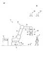
以下、本開示の実施の形態を図面に基づいて詳細に説明する。なお、以下に説明する種々の実施形態において、同様の要素には同じ符号を付し、重複する説明を省略する。まず、図1及び図2を参照して、一実施形態に係るロボットシステム10について説明する。 ロボットシステム10は、作業員Aと協働して、作業対象物Wを予め定められた目的位置まで運搬する作業を行うためのシステムである。ロボットシステム10は、ロボット12、力検出装置14、検出装置16A及び16B、及び制御装置18を備える。制御装置18は、例えばプロセッサ(CPU、GPU等)及びメモリ(RAM、ROM等)を有し、ロボット12、力検出装置14、並びに検出装置16A及び16Bを制御する。 Hereinafter, embodiments of the present disclosure will be described in detail with reference to the drawings. In various embodiments described below, similar elements are designated by the same reference numerals, and duplicate description will be omitted. First, the
本実施形態においては、ロボット12は、垂直多関節ロボットであって、ロボットベース20、旋回胴22、ロボットアーム24、手首部32、及びロボットハンド26を有する。ロボットベース20は、作業セルの床の上に固定されたベースプレート38に対して固定されている。旋回胴22は、ロボットベース20に鉛直軸周りに旋回可能に設けられている。ロボットアーム24は、旋回胴22に回転可能に取り付けられた下腕部28と、該下腕部28の先端に回転可能に取り付けられた上腕部30とを有する。 In the present embodiment, the
手首部32は、上腕部30の先端に連結され、ロボットハンド26を回転可能に支持している。ロボットハンド26は、手首部32に連結されたハンドベース34と、該ハンドベース34に開閉可能に設けられた複数の指部36とを有する。ロボットハンド26は、指部36で作業対象物Wを把持したり、解放したりする。 The
ロボット12は、複数のサーボモータ40(図2)を有する。これらサーボモータ40は、ロボット12の各コンポーネント(すなわち、ロボットベース20、旋回胴22、ロボットアーム24、手首部32)に内蔵され、これらコンポーネントを駆動軸周りに回転させる。 The
力検出装置14は、手首部32とロボットハンド26との間に介挿されている。本実施形態においては、力検出装置14は、複数の歪ゲージ(図示せず)を有する6軸力覚センサを有し、ロボットハンド26に加わる外力を検出する。なお、力検出装置14は、6軸力覚センサに限らず、ロボットハンド26に加わる外力を検出可能であれば、如何なる装置を有してもよい。 The
検出装置16Aは、作業対象物Wを検出する。具体的には、検出装置16Aは、作業セル内の所定の位置に固定され、作業対象物Wを撮像し、撮像した画像に基づいて、該作業対象物Wのロボット座標系CRにおける位置を検出する。なお、本稿において作業対象物及びロボットの「位置」とは、位置及び姿勢を意味する場合がある。The
検出装置16Bは、作業対象物Wに対する作業員Aの所定の動作を検出する。具体的には、検出装置16Bは、作業員Aを撮像し、撮像した画像に基づいて、作業対象物Wに対する作業員Aの所定の動作を検出する(いわゆる、光学式モーションキャプチャ)。なお、検出装置16Bが検出する作業員Aの所定の動作については、後述する。例えば、検出装置16A及び16Bは、撮像素子、フォーカスレンズ等の光学レンズ、及び画像処理プロセッサ(例えばGPU)等を有する3次元視覚センサから構成されてもよい。 The
次に、図3を参照して、ロボットシステム10の動作について説明する。図3に示す動作フローは、制御装置18が、オペレータ、上位コントローラ、又はロボットプログラムから運転開始指令を受け付けたときに、開始する。本実施形態においては、図3に示す動作フローが開始されたとき、図4に示すように、複数の作業対象物W1〜W4がランダムに載置されている。Next, the operation of the
ステップS1において、検出装置16Aは、各々の作業対象物W1〜W4を検出する。具体的には、制御装置18は、検出装置16Aに位置検出指令を送り、該位置取得指令を受け付けて、検出装置16Aは、各々の作業対象物W1〜W4を撮像し、撮像した画像に基づいて、各々の作業対象物W1〜W4のロボット座標系CRにおける位置を取得する。In step S1, the
ステップS2において、検出装置16Bは、作業員Aの動作の検出を開始する。具体的には、制御装置18は、検出装置16Bに動作検出指令を送り、該動作検出指令を受け付けて、検出装置16Bは、作業員Aを連続的に(例えば、所定の周期で)撮像し、撮像した画像に基づいて、作業員Aの動作を継続的に検出する。 In step S2, the
ここで、検出装置16Bは、作業員Aの第1の動作及び第2の動作を検出するように構成される。この第1の動作は、作業対象物Wを把持する作業をロボット12に行わせるために、作業員Aが、ロボット12に把持させるべき作業対象物Wに対して行う所定の動作である。この第1の動作の例について、図4〜図7を参照して説明する。 Here, the
図4に示す例においては、第1の動作は、作業員Aが、ロボット12に把持させるべき1つの作業対象物W1に接近する動作として定められている。検出装置16Bは、作業員Aを連続的に撮像し、撮像した画像と、上述のステップS1で取得した、各々の作業対象物W1〜W4の位置の情報とから、作業員Aと作業対象物W1との距離d1、作業員Aと作業対象物W2との距離d2、作業員Aと作業対象物W3との距離d3、及び、作業員Aと作業対象物W4との距離d4をそれぞれ算出する。In the example shown in FIG. 4, the first operation is defined as an operation in which the worker A approachesone work object W1 to be gripped by the robot 12. The
そして、検出装置16Bは、算出した各々の距離d1〜d4が、予め定められた閾値dth1以下となったか否かを判定する。そして、距離d1〜d4のいずれかが閾値dth1以下となったときに、第1の動作として、作業対象物W1〜W4のいずれかに作業員Aが接近したことを検出する。Then, the
図4に示す例においては、作業員Aが作業対象物W1に接近しており、検出装置16Bは、距離d1が閾値dth1以下となったときに、作業員Aが作業対象物W1に接近する第1の動作を検出するとともに、作業対象物W1をロボット12の把持対象として特定する。代替的には、検出装置16Bは、連続して撮像した画像から作業員Aの移動方向Eを算出し、移動方向Eと交差する作業対象物W1を、ロボット12の把持対象として特定してもよい。In the example shown in FIG. 4, the operator A has approached the work object W1, detection device 16B, when the distance d1 becomes the threshold value dth1 or less, Worker A work object W detects a first operation to approach1, identifies the work object W1 as the gripping target of the
図5に示す例においては、第1の動作は、作業員Aがロボット12に把持させるべき1つの作業対象物W1を手Bで把持する動作として定められている。検出装置16Bは、作業員Aを連続的に撮像し、いわゆるモーションキャプチャ技術を用いて、作業員Aが作業対象物W1を把持する第1の動作を検出するとともに、作業員Aが把持した作業対象物W1を、ロボット12の把持対象として特定する。In the example shown in FIG. 5, the first operation, the operator A is defined as an operation for gripping the one work object W1 to be gripped by the
一例として、検出装置16Bは、作業員Aが作業対象物W1を把持する動作の基準動作パターンを記憶(又は、機械学習)しておく。そして、検出装置16Bは、ステップS2の開始後に作業員Aの動作を監視しているときに、実際の作業員Aの動作が、該基準動作パターンと合致するか否かを判定し、合致すると判定したときに、作業員Aが作業対象物W1を把持する第1の動作を行ったことを検出する。As an example, the
図6に示す例においては、第1の動作は、作業員Aがロボット12に把持させるべき1つの作業対象物W1を指Cで指す動作として定められている。検出装置16Bは、作業員Aを連続的に撮像し、いわゆるモーションキャプチャ技術を用いて、作業員Aが作業対象物W1を指す動作及び指す方向Dを検出するとともに、指す方向Dと交差する作業対象物W1を、ロボット12の把持対象として特定する。In the example shown in FIG. 6, the first operation, the operator A are determined one work object W1 to be gripped by the
図7に示す例においては、第1の動作は、作業員Aがロボット12に把持させるべき1つの作業対象物W1を手Bでタップする動作として定められている。検出装置16Bは、作業員Aを連続的に撮像し、いわゆるモーションキャプチャ技術を用いて、作業員Aが作業対象物W1をタップする動作を検出するとともに、タップされた作業対象物W1を、ロボット12の把持対象として特定する。In the example shown in FIG. 7, the first operation is defined as an operation in which the worker Ataps one work object W1 to be gripped by the
この場合において、作業員Aは、作業対象物W1を予め定められた回数n(nは2以上の整数)だけタップし、検出装置16Bは、作業員Aが作業対象物W1をn回タップする動作を検出したときに、該動作を第1の動作として検出してもよい。なお、検出装置16Bが検出する作業員Aの第2の動作については、後述する。In this case, the worker Ataps the work object W 1 a predetermined number of times n (n is an integer of 2 or more), and the
ステップS3において、検出装置16Bは、作業員Aの第1の動作を検出したか否かを判定する。具体的には、検出装置16Bは、例えば図4〜図7で説明したような作業員Aの第1の動作を検出したか否かを判定する。検出装置16Bは、作業員Aの第1の動作を検出した場合、YESと判定し、ロボット12の把持対象となる作業対象物W1を特定する。そして、検出装置16Aは、検出装置16Bが把持対象として特定した作業対象物W1のロボット座標系CRにおける位置の情報を制御装置18に送り、ステップS5へ進む。一方、検出装置16Bは、第1の動作を検出していない場合はNOと判定し、ステップS4へ進む。In step S3, the
ステップS4において、制御装置18は、オペレータ、上位コントローラ、又はロボットプログラムから運転終了指令を受け付けたか否かを判定する。制御装置18は、運転終了指令を受け付けた(すなわち、YES)と判定した場合、図3に示すフローを終了する一方、運転終了指令を受け付けていない(すなわち、NO)と判定した場合、ステップS3へ戻る。 In step S4, the
ステップS5において、制御装置18は、ロボット12を、作業対象物W1を把持するための位置(以下、把持位置とする)へ移動させて、ロボット12に作業対象物W1を把持させる。具体的には、制御装置18は、上述のステップS3で検出装置16Aから受信した作業対象物W1の位置の情報に基づいてロボット12の各サーボモータ40へ指令を送り、該ロボット12を把持位置へ移動させる。In step S5, the control device 18moves the robot 12 to a position for gripping the work object W 1 (hereinafter referred to as a grip position), and causes the
ロボット12が把持位置に配置されたとき、作業対象物W1は、ロボットハンド26の指部36の間に配置される。このように、制御装置18は、検出装置16Bが作業員Aの第1の動作を検出したことをトリガーとして、ロボット12を把持位置へ移動させる作業(すなわち、各サーボモータ40への指令)を開始する。When the
次いで、制御装置18は、ロボットハンド26を動作させて指部36を閉じる。これにより、ロボット12は、作業対象物W1をロボットハンド26で把持する。このように、本実施形態においては、制御装置18は、検出装置16Bが作業員Aの第1の動作を検出したときにロボット12に予め定めた作業(ロボット12を把持位置へ移動させ、作業対象物W1を把持する作業)を実行させるロボット制御部42(図2)として機能する。Next, the
なお、このステップS5において、制御装置18は、検出装置16Bが連続的に検出している作業員Aの動作の情報に基づいて、該作業員Aとの衝突を避けることができるロボット12の動作経路を演算してもよい。例えば、制御装置18は、検出装置16Bから作業員Aの動作経路を示すデータを取得し、作業員Aの動作経路を避ける(交差しない)ようなロボット12の動作経路を演算する。そして、制御装置18は、演算した動作経路に沿ってロボット12を動作させる。この構成によれば、ロボット12と作業員Aとの衝突を避けることができる。 In step S5, the
ステップS5でロボット12が作業対象物W1を把持する作業が完了したとき、作業員Aは、作業対象物W1をロボット12と協働で目的位置まで運搬するために、該ロボット12に外力Fを加える。一例として、作業員Aは、ロボット12が把持する作業対象物W1を持ち上げて、該作業対象物W1を目的位置の方向へ押す。このときに作業員Aが作業対象物Wに加えた外力Fは、作業対象物W1を通して、ロボットハンド26に加えられることになる。When working the
他の例として、作業員Aは、ロボットハンド26に手Bで直接外力Fを加えてもよい。この場合において、ロボットハンド26(例えば、ハンドベース34)に作業員Aが把持可能なハンドル(図示せず)を設けて、作業員Aは、該ハンドルを手Bで把持して、該ハンドルを通してロボットハンド26に外力Fを加えてもよい。 As another example, the worker A may apply an external force F directly to the
本実施形態においては、制御装置18は、ステップS5の完了後、検出装置16Bが検出する作業員Aの動作に追従して検出装置16Aが検出する目標位置へロボット12をアプローチさせる位置追従制御(ステップS2〜S5)から、ロボット12に加わる外力Fに従って該ロボット12を制御するリードスルー制御(後述のステップS6〜S10)に切り換える。 In the present embodiment, after the completion of step S5, the
ステップS6において、制御装置18は、ロボット12に加わる外力Fの検出を開始する。具体的には、制御装置18は、力検出装置14が検出した外力Fのデータを、該力検出装置14から連続的に(例えば、周期的に)取得する動作を開始する。作業員Aが作業対象物W1を通して(又は手Bで直接)ロボット12に加えた外力F(大きさ及び方向)は、力検出装置14によって検出される。In step S6, the
ステップS7において、制御装置18は、直近に力検出装置14が検出した外力Fが、予め定められた閾値Fth以上となったか否かを判定する。制御装置18は、直近の外力Fが、F≧Fthである(すなわち、YES)と判定した場合、ステップS10へ進む一方、F<Fthである(すなわち、NO)と判定した場合、ステップS8へ進む。In step S7, the
ステップS8において、制御装置18は、上述のステップS4と同様に、運転終了指令を受け付けたか否かを判定する。制御装置18は、運転終了指令を受け付けた(すなわち、YES)と判定した場合、図3に示すフローを終了する一方、運転終了指令を受け付けていない(すなわち、NO)と判定した場合、ステップS9へ進む。 In step S8, the
ステップS9において、制御装置18は、警告信号を生成する。例えば、制御装置18は、「ロボットを目的位置へ向かってガイドしてください」という音声又は画像の形式の警告信号を生成し、スピーカ又はディスプレイ(図示せず)を通して、警告を出力してもよい。ステップS9の後、制御装置18は、ステップS7へ戻る。 In step S9, the
ステップS10において、制御装置18は、直近に力検出装置14が検出した外力Fのデータに基づいて、ロボット12に作業対象物W1を運搬させる。具体的には、制御装置18は、直近に力検出装置14が検出した外力Fの方向を取得し、作業対象物W1を把持するロボットハンド26を外力Fの方向へ移動させるように、ロボット12を制御する。In step S10, the
制御装置18は、直近に力検出装置14が検出した外力Fの大きさを取得し、該外力Fの大きさに応じて、ロボットハンド26を外力Fの方向へ移動させる速度を制御してもよい。例えば、制御装置18は、該外力Fの大きさが大きくなる程、ロボットハンド26を移動させる速度を増大させるように、該ロボットハンド26の移動速度を制御してもよい。 Even if the
これにより、ロボット12は、図8に示すように、作業員Aがロボット12に加えた外力Fに従って、作業対象物W1を移動させる。なお、図8に示す例においては、作業員Aが、ロボット12とともに作業対象物W1を手Bで把持して、該作業対象物W1を通してロボット12に外力Fを加えている場合を示している。こうして、ロボット12は、作業員Aと協働で、作業対象物W1を目的位置へ向かって運搬する。Thus, the
なお、制御装置18は、ステップS10の実行中に、力検出装置14が検出した外力Fが、上限値FMAXを超えたか否かを判定し、外力Fが上限値FMAXを超えた(すなわち、F≧FMAX)場合に、ロボット12の動作を緊急停止してもよい。この上限値FMAXは、ステップS10の実行中にロボットハンド26又は作業対象物W1が、障害物と衝突したことを検出するために、上述の閾値Fthよりも大きな値として使用者によって予め定められる。The control device 18 determines whether or not the external force F detected by the force detecting device 14 exceeds the upper limit value F MAX during the execution of step S10, and the external force F exceeds the upper limit value FMAX (that is,). , F ≧ FMAX ), the operation of the
作業対象物W1を目的位置に移動させたとき、作業員Aは、第2の動作を行う。この第2の動作は、ロボット12に作業対象物W1を解放させるために作業員Aが行う、上述の第1の動作とは異なる所定の動作である。この第2の動作の例について、図9及び図10を参照して説明する。When the work object W1 is moved to the target position, the worker A performs the second operation. The second operation, the operator A is carried out in order to release the work object W1 to the
図9に示す例においては、第2の動作は、作業員Aが、ロボット12が把持している作業対象物W1から離れる動作として定められている。一例として、検出装置16Bは、作業員A及び作業対象物W1を連続的に撮像し、撮像した画像から、作業員Aと作業対象物W1との距離d1を算出する。検出装置16Bは、ステップS5を完了したとき、又はステップS10を開始したときに、作業員Aと作業対象物W1との距離d1を算出する動作を開始してもよい。In the example shown in FIG. 9, the second operation, the operator A has been determined as an operation away from the work object W1 of the
検出装置16Bは、算出した距離d1が、予め定められた閾値dth2以上となったか否かを判定する。そして、距離d1が閾値dth2以上となったときに、第2の動作として、作業員Aが作業対象物W1から離れたことを検出する。なお、閾値dth2は、上述の閾値dth1と同じ値であってもよいし、又は、異なる値であってもよい。The
図10に示す例においては、第2の動作は、作業員Aが作業対象物W1を把持していた手Bを開いて、該作業対象物W1を解放する動作として定められている。検出装置16Bは、作業員Aを連続的に撮像し、いわゆるモーションキャプチャ技術を用いて、作業員Aが作業対象物W1を把持していた手Bを開く動作を検出する。In the example shown in FIG. 10, the second operation, open the hand B the worker A had grips the work object W1, is defined as an operation to release the working object W1. Detector 16B is continuously image the operator A, using a so-called motion capture technique, detects the operation of opening the hand B the worker A had grips the work object W1.
一例として、検出装置16Bは、作業員Aが作業対象物W1を把持していた手Bを開く動作の基準動作パターンを記憶(又は、機械学習)しておく。そして、検出装置16Bは、ステップS10の実行中に作業員Aの動作を監視しているときに、実際の作業員Aの動作が、該基準動作パターンと合致するか否かを判定し、合致すると判定したときに、作業員Aが手Bを開く第2の動作を行ったことを検出してもよい。As an example, the
ステップS11において、検出装置16Bは、作業員Aの第2の動作を検出したか否かを判定する。具体的には、検出装置16Bは、例えば図9及び図10で説明したような作業員Aの第2の動作を検出したか否かを判定し、検出した場合はYESと判定し、ステップS12へ進む。一方、検出装置16Bは、作業員Aの第2の動作を検出していない場合はNOと判定し、ステップS7へ戻る。 In step S11, the
上述したように、本実施形態においては、検出装置16Bは、作業対象物W1の運搬前に作業員Aが行う第1の動作と、作業対象物W1を目的位置へ運搬したときに作業員Aが行う第2の動作とを検出する。よって、検出装置16Bは、少なくとも、作業対象物W1を運搬する前の作業員Aと、作業対象物W1を目的位置に運搬したときの作業員Aとを検出できるような位置に、設置される。As described above, in the present embodiment, the
ステップS12において、制御装置18は、ロボット12に作業対象物W1を解放させる。具体的には、制御装置18は、ロボットハンド26を動作させて指部36を開く。これにより、ロボットハンド26は、把持していた作業対象物W1を解放する。その結果、作業対象物W1は、目的位置に配置されることになる。In step S12, the
なお、ステップS11でYESと判定されたとき、このステップS12において、制御装置18は、作業対象物W1を解放する前に、ロボットプログラムに従ってロボット12を動作させて、ロボット12が把持している作業対象物W1を所定の方向(例えば、鉛直下方)へ移動させてもよい。When YES is determined in step S11, in step S12, the
例えば、ロボット12が作業対象物W1を、目的位置である載置台の鉛直上方まで移動させたときに、作業員Aが第2の動作を行ったとする。ステップS11で該第2の動作を検出したとき、制御装置18は、ステップS12において、ロボット12を動作させて作業対象物W1を鉛直下方へ移動させ、該作業対象物W1を載置台の上に載置したときに、ロボット12に作業対象物W1を解放させる。For example, suppose that the worker A performs the second operation when the
ここで、制御装置18は、ロボット12によって作業対象物W1を鉛直下方へ移動させているときに、力検出装置14が検出する外力を監視し、該外力のデータに基づいて、作業対象物W1が載置台に当接したか否かを検出してもよい。そして、制御装置18は、作業対象物W1が載置台に当接したことを検出したときに、ロボット12に作業対象物W1を解放させてもよい。Here, the
ステップS13において、制御装置18は、上述のステップS4と同様に、運転終了指令を受け付けたか否かを判定する。制御装置18は、運転終了指令を受け付けた(すなわち、YES)と判定した場合、図3に示すフローを終了する一方、運転終了指令を受け付けていない(すなわち、NO)と判定した場合、ステップS3へ戻る。 In step S13, the
そして、作業員Aは、他の作業対象物W2〜W4のいずれかに対して再度、第1の動作を行い、制御装置18は、ステップS3〜13のループを繰り返し実行することによって、作業員Aと協働で、ロボット12に作業対象物W2〜W4を目的位置まで順次運搬させることができる。Then, by the operator A, again for any of the
以上のように、本実施形態においては、制御装置18は、検出装置16Bが作業員Aの第1の動作を検出したときに、作業対象物Wに対しロボット12に予め定めた作業(把持位置への移動及び把持)を実行させている。この構成によれば、作業員Aは、装置を操作することなく、ロボット12を所望のタイミングで直感的に始動させることができる。したがって、作業員Aの動きに高度に合わせるように、ロボット12に協働作業させることができる。 As described above, in the present embodiment, when the
また、本実施形態においては、制御装置18は、ステップS5の終了後、検出装置16Bの検出データに基づく位置追従制御(ステップS2〜S5)から、力検出装置14の検出データに基づくリードスルー制御(ステップS6〜S10)に切り換えている。この構成によれば、作業員Aの第1の動作によってロボット12を始動させて、該ロボット12と協働で作業対象物W1を目的位置まで運搬させる一連の作業を、円滑に行うことができる。Further, in the present embodiment, after the end of step S5, the
また、本実施形態においては、制御装置18は、検出装置16Bが作業員Aの第2の動作を検出したときに、ロボット12に作業対象物W1を解放させている。この構成によれば、作業員Aは、装置を操作することなく、作業対象物W1を目的位置に運搬したタイミングで直感的に、ロボット12に該作業対象物W1を解放させることができる。In the present embodiment, the
なお、本実施形態においては、検出装置16Aが、作業対象物W1〜W4のロボット座標系CRにおける位置を検出する場合について述べた。しかしながら、これに限らず、例えば、作業対象物W1〜W4を、治具等によって、ロボット座標系CRにおける所定の位置に配置し、制御装置18が、これら作業対象物W1〜W4のロボット座標系CRにおける位置を予め記憶していてもよい。In the present embodiment, the
この場合、検出装置16Aは、ステップS1において、各々の作業対象物W1〜W4の存在を検出するだけで、作業対象物W1〜W4のロボット座標系CRにおける位置を取得しなくてもよい。そして、ステップS3において、検出装置16Bは、作業員Aの第1の動作の対象となった作業対象物W1を特定し、ステップS5において、制御装置18は、予め記憶された作業対象物W1の位置の情報に基づいて、ロボット12を把持位置へ移動させてもよい。In this case, the
また、図3に示すフローにおいて、制御装置18は、上述のステップS6を、ステップS5よりも前に(例えば、ステップS2の直前又は直後のタイミングで)実行し、該ステップS5を実行しているときに、力検出装置14が検出する外力Fが上限値FMAXを超えたときに、ロボットハンド26が作業員Aと衝突したと判定し、該ロボット12を緊急停止してもよい。Further, in the flow shown in FIG. 3, the
この場合において、制御装置18は、ロボット12が作業員Aと衝突したと判定したときに、ロボット12と作業員Aとの衝突を表す音声又は画像の形式の警告信号を生成し、スピーカ又はディスプレイを通して、警告を出力してもよい。 In this case, when the
また、ロボットシステム10から力検出装置14を省略することができる。この場合において、制御装置18は、図3中のステップS6〜S12の代わりに、ロボットプログラムに従ってロボット12を動作させて、作業対象物W1を目的位置まで、ロボット12に自動で運搬させてもよい。Further, the
このロボットプログラムは、例えば、作業対象物W1を目的位置まで運搬させる動作をロボット12に教示することによって、構築され得る。また、作業員Aの第1の動作及び第2動作は、上述した動作に限定されず、検出装置16Bが検出可能であれば、如何なる動作であってもよい。The robot program, for example, by teaching the operation to transport the workpiece W1 to the target position to the
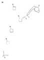
次に、図11及び図12を参照して、他の実施形態に係るロボットシステム50について説明する。ロボットシステム50は、作業員Aと協働で、作業対象物Vを部品Fに締結する作業を行うためのシステムである。ロボットシステム50は、上述のロボットシステム10と、力検出装置14を備えていない点、及び、ロボット52の構成において、相違する。 Next, the
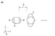
ロボット52は、垂直多関節ロボットであって、ロボットベース20、旋回胴22、ロボットアーム24、手首部32、及びエンドエフェクタ54を有する。エンドエフェクタ54は、手首部32に取り付けられ、工具56を有する。工具56は、軸線Oを有し、エンドエフェクタ54は、工具56を軸線O周りに回転駆動する。作業対象物Vは、例えばボルトであって、エンドエフェクタ54は、工具56に作業対象物Vを係合させた状態で該工具56を回転駆動することによって、該作業対象物Vを部品Fに締結することができる。 The
次に、図13を参照して、ロボットシステム50の動作について説明する。図13に示す動作フローは、制御装置18が、オペレータ、上位コントローラ、又はロボットプログラムから運転開始指令を受け付けたときに、開始する。本実施形態においては、図14に示すように、複数の作業対象物V1〜V4が部材Fに設置されている。Next, the operation of the
ステップS21において、検出装置16Aは、各々の作業対象物V1〜V4を検出する。具体的には、制御装置18は、検出装置16Aに位置検出指令を送り、該位置取得指令を受け付けて、検出装置16Aは、各々の作業対象物V1〜V4を撮像し、撮像した画像に基づいて、各々の作業対象物V1〜V4(例えば、中心)のロボット座標系CRにおける位置を取得する。In step S21, the
ステップS22において、検出装置16Bは、作業員Aの動作の検出を開始する。具体的には、制御装置18は、検出装置16Bに動作検出指令を送り、該動作検出指令を受け付けて、検出装置16Bは、作業員Aを連続的に撮像し、撮像した画像に基づいて、作業員Aの動作を継続的に検出する。 In step S22, the
ここで、検出装置16Bは、作業員Aの所定の動作を検出するように構成される。この所定の動作は、作業対象物Vの締結作業をロボット52に行わせるために、作業員Aが、締結すべき作業対象物Vに対して行う動作である。この所定の動作の例について、図14を参照して説明する。 Here, the
図14に示す例においては、所定の動作は、作業員Aが、締結すべき1つの作業対象物V1を指Cで指す動作として定められている。検出装置16Bは、作業員Aを連続的に撮像し、いわゆるモーションキャプチャ技術を用いて、作業員Aが作業対象物V1を指す動作及び指す方向Gを検出するとともに、指す方向Gと交差する作業対象物V1を締結対象として特定する。In the example shown in FIG. 14, a predetermined operation, the operator A has defined one should conclude the work object V1 as an operation to refer a
ステップS23において、検出装置16Bは、作業員Aの所定の動作を検出したか否かを判定する。具体的には、検出装置16Bは、例えば図14で説明したような作業員Aの動作を検出したか否かを判定し、検出した場合はYESと判定し、締結対象の作業対象物V1を特定する。In step S23, the
そして、検出装置16Aは、締結対象として特定した作業対象物V1のロボット座標系CRにおける位置の情報を制御装置18に送り、ステップS25へ進む。一方、検出装置16Bは、作業員Aの所定の動作を検出していない場合はNOと判定し、ステップS24へ進む。The
ステップS24において、制御装置18は、上述のステップS4と同様に、運転終了指令を受け付けたか否かを判定する。制御装置18は、運転終了指令を受け付けた(すなわち、YES)と判定した場合、図13に示すフローを終了する一方、運転終了指令を受け付けていない(すなわち、NO)と判定した場合、ステップS23へ戻る。 In step S24, the
ステップS25において、制御装置18は、ロボット制御部42として機能し、ロボット52を、作業対象物V1に対して締結作業を行うための位置(以下、締結位置とする)へ移動させて、ロボット52に、作業対象物V1を部品Fへ締結させる。具体的には、制御装置18は、上述のステップS23で検出装置16Aから受信した作業対象物V1の位置の情報に基づいてロボット52の各サーボモータ40へ指令を送り、ロボット52を締結位置へ移動させる。In step S25, the
ロボット52が締結位置に配置されたとき、工具56の軸線Oと作業対象物V1の中心軸とが一致し、工具56と作業対象物V1とが相対回転不能に係合する。このように、制御装置18は、検出装置16Bが作業員Aの所定の動作を検出したことをトリガーとして、ロボット52を締結位置へ移動させる作業(すなわち、サーボモータ40への指令)を開始する。When the
次いで、制御装置18は、エンドエフェクタ54を動作させて、工具56を軸線O周りに回転駆動する。これにより、作業対象物V1は、工具56によって回転されて、部品Fに締結される。なお、このステップS25において、制御装置18は、検出装置16Bが連続的に検出している作業員Aの動作の情報に基づいて、該作業員Aとの衝突を避けることができるロボット52の動作経路を演算してもよい。そして、制御装置18は、演算した動作経路に沿ってロボット52を動作させてもよい。この構成によれば、ロボット52と作業員Aとの衝突を防止できる。Next, the
ステップS26において、制御装置18は、上述のステップS4と同様に、運転終了指令を受け付けたか否かを判定する。制御装置18は、運転終了指令を受け付けた(すなわち、YES)と判定した場合、図13に示すフローを終了する一方、運転終了指令を受け付けていない(すなわち、NO)と判定した場合、ステップS23へ戻る。 In step S26, the
そして、作業員Aは、他の作業対象物V2〜V4のいずれかに対して再度、第1の動作を行い、制御装置18は、ステップS23〜26のループを繰り返し実行することによって、作業員Aと協働で、ロボット52に作業対象物V2〜V4の締結作業を実行させることができる。Then, by the operator A, again for any
以上のように、本実施形態においては、制御装置18は、検出装置16Bが作業員Aの所定の動作を検出したときに、作業対象物Vに対しロボット52に予め定めた作業(締結位置への移動、及び作業対象物の締結)を実行させている。この構成によれば、作業員Aは、装置を操作することなく、ロボット52を所望のタイミングで直感的に始動させることができる。 As described above, in the present embodiment, when the
なお、本実施形態において、検出装置16Bが検出する作業員Aの所定の動作は、図4に示す接近動作、図5に示す把持動作、又は図7に示すタップ動作であってもよい。また、本実施形態においては、ロボット52が作業対象物Vを締結する作業を行う場合について述べた。しかしながら、これに限らず、ロボット52は、例えば、作業対象物に対して溶接作業を行うものであってもよいし、又は、他の如何なる作業を行うものであってもよい。ロボット52が溶接作業を行う場合、ロボット52のエンドエフェクタ54は、溶接トーチを有し得る。 In the present embodiment, the predetermined operation of the worker A detected by the
また、上述の実施形態においては、ロボット12、52が、複数の作業対象物W、Vに対して作業を行う場合について述べたが、1つのみの作業対象物に対して作業をするものであってもよい。また、検出装置16Bを、カメラと、制御装置18のプロセッサとによって構成してもよい。具体的には、カメラによって作業員Aを撮像し、制御装置18のプロセッサが、カメラの撮像画像を画像解析して、作業員Aの動作を検出してもよい。 Further, in the above-described embodiment, the case where the
また、検出装置16Bは、3次元視覚センサに限らず、作業員Aの身体に設置した複数の慣性センサを有してもよい。この場合において、制御装置18は、複数の慣性センサからの出力データに基づいて、作業員Aの動作を検出してもよい。また、上述した形態に限らず、検出装置16Bは、如何なるタイプのセンサを有してもよいし、如何なるタイプのモーションキャプチャ技術を用いて作業員Aの動作を検出してもよい。 Further, the
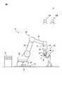
また、検出装置16A及び16Bは、1つの検出装置から構成されてもよい。このような実施形態を図15に示す。図15に示すロボットシステム10’は、1つの検出装置16を備える。検出装置16は、例えば3次元視覚センサから構成され、上述の検出装置16A及び16Bの機能を担う。具体的には、検出装置16は、作業対象物Wを検出するとともに、該作業対象物Wに対する作業員Aの所定の動作を検出する。この検出装置16は、上述のロボットシステム50に適用することもできる。 Further, the
また、ロボットシステム10において、力検出装置14は、如何なる位置に設けられてもよい。以下、図16を参照して、力検出装置14の設置位置の他の例について説明する。図16に示すロボットシステム10”においては、力検出装置14は、ロボットベース20とベースプレート38との間に介挿されている。この例においては、力検出装置14は、ロボット12のコンポーネント(すなわち、ロボットベース20、旋回胴22、ロボットアーム24、手首部32、又はロボットハンド26)に掛かる外力Fを検出できる。 Further, in the
なお、力検出装置14は、6軸力覚センサに限らず、例えば、各サーボモータ40の駆動軸に掛かるトルクを検出するトルクセンサを有し、該トルクセンサの検出値から、ロボット12のコンポーネントに掛かる外力Fを検出するように構成されてもよい。又は、力検出装置14は、各サーボモータ40からフィードバックされる外乱トルクから、ロボット12のコンポーネントに掛かる外力Fを検出するように構成されてもよい。 The
また、ロボット12(又は52)は、垂直多関節ロボットに限らず、水平多関節ロボット、パラレルリンクロボット、又はローダ等、如何なるタイプのロボットであってもよい。また、ロボット12(又は52)は、ロボットベース20、旋回胴22、ロボットアーム24、手首部32、及びロボットハンド26(又はエンドエフェクタ54)を有するロボット本体部と、該ロボット本体部を任意の方向へ移動させる走行装置とを有してもよい。この場合において、制御装置18は、上述のステップS5及びS10(又は、ステップS25)において、該走行装置を動作させて、ロボット本体部を移動させてもよい。 Further, the robot 12 (or 52) is not limited to the vertical articulated robot, and may be any type of robot such as a horizontal articulated robot, a parallel link robot, or a loader. Further, the robot 12 (or 52) has an arbitrary robot body portion having a
以上、実施形態を通じて本開示を説明したが、上述の実施形態は、特許請求の範囲に係る発明を限定するものではない。 Although the present disclosure has been described above through the embodiments, the above-described embodiments do not limit the invention according to the claims.
10,10’,10”,50 ロボットシステム
12,52 ロボット
14 力検出装置
16,16A,16B 検出装置
18 制御装置
42 ロボット制御部10, 10', 10 ", 50
Claims (5)
Translated fromJapanese作業対象物を検出するとともに、該作業対象物に対する人の所定の動作を検出する検出装置と、
前記検出装置が第1の前記動作を検出したときに、該検出装置が検出した前記作業対象物を前記ロボットに把持させて該ロボットによって該作業対象物を運搬する作業を開始するロボット制御部と、を備え、
前記検出装置は、
人と前記作業対象物との間の距離を算出し、該距離が予め定められた閾値以下となったときに、前記第1の動作として、人が前記作業対象物に接近する動作を検出するように構成され、
前記作業の間、人の前記動作を監視し、
前記ロボット制御部は、前記検出装置が、前記作業の開始後に前記第1の動作とは異なる第2の前記動作を検出したときに、前記ロボットに該作業対象物を解放させる、ロボットシステム。With a robot
A detection device that detects a work object and also detects a person's predetermined movement with respect to the work object.
When the detection device detects the first operation, the robot control unit causes the robot to grasp the work object detected by the detection device and starts the work of transporting the work object by the robot. , Equipped with
The detection device is
The distance between the person and the work object is calculated, and when the distance becomes equal to or less than a predetermined threshold value, the action of the person approaching the work object is detected as the first operation. Is configured as
During the work, monitor the movement of the person and
The robot control unit is a robot system in which when the detection device detects a second operation different from the first operation after the start of the operation, the robot causes the robot to release the work object.
前記ロボット制御部は、前記力検出装置が検出した前記外力のデータに基づき、前記ロボットに前記作業対象物を運搬させる、請求項1又は2に記載のロボットシステム。Further equipped with a force detecting device for detecting an external force applied to the robot,
The robot system according to claim 1 or 2, wherein the robot control unit causes the robot to carry the work object based on the external force data detected by the force detection device.
作業対象物を検出し、
前記作業対象物に対する人の所定の動作を検出し、
人と前記作業対象物との間の距離を算出し、該距離が予め定められた閾値以下となったときに、第1の前記動作として、人が前記作業対象物に接近する動作を検出し、
前記第1の動作を検出したときに、検出した前記作業対象物を前記ロボットに把持させて該ロボットによって該作業対象物を運搬する作業を開始し、
前記作業の間、人の前記動作を監視し、
前記作業の開始後に前記第1の動作とは異なる第2の前記動作を検出したときに、前記ロボットに該作業対象物を解放させる、制御方法。It ’s a robot control method.
Detect the work object,
Detecting a person's predetermined movement with respect to the work object,
The distance between the person and the work object is calculated, and when the distance becomes equal to or less than a predetermined threshold value, the action of the person approaching the work object is detected as the first operation. ,
Wherein when thefirst detecting theoperation, the detected said work object by grasping the robot to begin to carry the working object by the robot,
During the work, monitor the movement of the person and
A control method for causing the robot to release the work object when a second movement different from the first movement is detected after the start of the work.
前記把持する位置で前記ロボットに前記作業対象物を把持させ、
力検出装置が検出した、前記ロボットに加わる外力のデータに基づき、前記ロボットに前記作業対象物を運搬させる、請求項4に記載の制御方法。When the first motion is detected, the robot is moved to a position where the work object is gripped based on the detected position of the work object.
The robot is made to grip the work object at the gripping position.
The control method according toclaim 4 , wherein the robot is made to carry the work object based on the data of the external force applied to the robot detected by the force detection device.
Priority Applications (4)
| Application Number | Priority Date | Filing Date | Title |
|---|---|---|---|
| JP2018199338AJP6916157B2 (en) | 2018-10-23 | 2018-10-23 | Robot systems that collaborate with people and robot control methods |
| US16/571,206US11235463B2 (en) | 2018-10-23 | 2019-09-16 | Robot system and robot control method for cooperative work with human |
| DE102019007186.7ADE102019007186B4 (en) | 2018-10-23 | 2019-10-16 | Robot system and robot control method for cooperative work with humans |
| CN201911002472.XACN111085993B (en) | 2018-10-23 | 2019-10-21 | Robot system for working in collaboration with humans and robot control method |
Applications Claiming Priority (1)
| Application Number | Priority Date | Filing Date | Title |
|---|---|---|---|
| JP2018199338AJP6916157B2 (en) | 2018-10-23 | 2018-10-23 | Robot systems that collaborate with people and robot control methods |
Publications (2)
| Publication Number | Publication Date |
|---|---|
| JP2020066080A JP2020066080A (en) | 2020-04-30 |
| JP6916157B2true JP6916157B2 (en) | 2021-08-11 |
Family
ID=70280394
Family Applications (1)
| Application Number | Title | Priority Date | Filing Date |
|---|---|---|---|
| JP2018199338AActiveJP6916157B2 (en) | 2018-10-23 | 2018-10-23 | Robot systems that collaborate with people and robot control methods |
Country Status (4)
| Country | Link |
|---|---|
| US (1) | US11235463B2 (en) |
| JP (1) | JP6916157B2 (en) |
| CN (1) | CN111085993B (en) |
| DE (1) | DE102019007186B4 (en) |
Families Citing this family (7)
| Publication number | Priority date | Publication date | Assignee | Title |
|---|---|---|---|---|
| KR102716734B1 (en)* | 2018-10-05 | 2024-10-15 | 소니그룹주식회사 | Information processing device, control method and program |
| JP7211007B2 (en)* | 2018-10-30 | 2023-01-24 | セイコーエプソン株式会社 | Control device, robot system and control method |
| JP7036078B2 (en)* | 2019-03-28 | 2022-03-15 | オムロン株式会社 | Control system, control method, and control unit |
| JP7458818B2 (en)* | 2020-02-21 | 2024-04-01 | キヤノン株式会社 | Robot device, interface device, control device, end effector, control method, method for manufacturing articles using robot device, program, and recording medium |
| EP4131139A1 (en)* | 2021-08-03 | 2023-02-08 | Sick Ag | Sensor assembly and method for securing a supervised area |
| JP2024002367A (en)* | 2022-06-24 | 2024-01-11 | トヨタ車体株式会社 | Conveying system |
| US20240326244A1 (en)* | 2023-03-30 | 2024-10-03 | Omron Corporation | Control of robotic arm and end effector via virtual force sensing |
Family Cites Families (27)
| Publication number | Priority date | Publication date | Assignee | Title |
|---|---|---|---|---|
| US5798627A (en)* | 1995-01-04 | 1998-08-25 | Gilliland; Malcolm T. | Method for simultaneous operation of robot welders |
| SE526119C2 (en)* | 2003-11-24 | 2005-07-05 | Abb Research Ltd | Method and system for programming an industrial robot |
| JP5338297B2 (en)* | 2008-12-19 | 2013-11-13 | 株式会社安川電機 | Robot control device |
| JP4648486B2 (en)* | 2009-01-26 | 2011-03-09 | ファナック株式会社 | Production system with cooperative operation area between human and robot |
| JP5464514B2 (en)* | 2009-08-21 | 2014-04-09 | 公立大学法人首都大学東京 | Robot control apparatus, robot control method, robot control program, and robot |
| CN102292194B (en)* | 2009-08-21 | 2015-03-04 | 松下电器产业株式会社 | Robot arm control device and control method, assembly robot, robot arm control program, and robot arm control integrated circuit |
| JP2013111737A (en)* | 2011-12-01 | 2013-06-10 | Sony Corp | Robot apparatus, control method thereof, and computer program |
| WO2013175777A1 (en)* | 2012-05-23 | 2013-11-28 | パナソニック株式会社 | Robot, robot control device, control method, and control program |
| JP5549724B2 (en)* | 2012-11-12 | 2014-07-16 | 株式会社安川電機 | Robot system |
| JP6221224B2 (en)* | 2012-11-27 | 2017-11-01 | セイコーエプソン株式会社 | Robot system, program, production system and robot |
| WO2014093822A1 (en)* | 2012-12-14 | 2014-06-19 | Abb Technology Ag | Bare hand robot path teaching |
| JP6042291B2 (en)* | 2013-08-27 | 2016-12-14 | 株式会社デンソーアイティーラボラトリ | Robot, robot control method, and robot control program |
| JP6397226B2 (en)* | 2014-06-05 | 2018-09-26 | キヤノン株式会社 | Apparatus, apparatus control method, and program |
| JP6344084B2 (en)* | 2014-06-20 | 2018-06-20 | オムロン株式会社 | Worker terminal for robot operation |
| US9919421B2 (en)* | 2015-04-15 | 2018-03-20 | Abb Schweiz Ag | Method and apparatus for robot path teaching |
| JP6455310B2 (en)* | 2015-05-18 | 2019-01-23 | 本田技研工業株式会社 | Motion estimation device, robot, and motion estimation method |
| WO2017033365A1 (en) | 2015-08-25 | 2017-03-02 | 川崎重工業株式会社 | Remote control robot system |
| DE102015012959B4 (en)* | 2015-10-08 | 2019-01-17 | Franka Emika Gmbh | Robot system and method for controlling a robot system |
| JP6577326B2 (en)* | 2015-10-16 | 2019-09-18 | ファナック株式会社 | Robot control apparatus, robot system, and method for controlling robot that carries objects in cooperation with human |
| CN109219856A (en)* | 2016-03-24 | 2019-01-15 | 宝利根 T·R 有限公司 | For the mankind and robot cooperated system and method |
| CN107717981B (en)* | 2016-08-12 | 2021-01-05 | 财团法人工业技术研究院 | Control device of mechanical arm and teaching system and method thereof |
| CN107717982B (en)* | 2016-08-12 | 2020-09-25 | 财团法人工业技术研究院 | Control device and operation method of mechanical arm |
| JP6549545B2 (en) | 2016-10-11 | 2019-07-24 | ファナック株式会社 | Control device and robot system for learning a human action and controlling a robot |
| US10427306B1 (en)* | 2017-07-06 | 2019-10-01 | X Development Llc | Multimodal object identification |
| JP6875228B2 (en)* | 2017-08-23 | 2021-05-19 | 株式会社日立製作所 | Robot procurement equipment and robot procurement method |
| US10898999B1 (en)* | 2017-09-18 | 2021-01-26 | X Development Llc | Selective human-robot interaction |
| EP3591521B1 (en)* | 2018-07-05 | 2023-07-26 | Honda Research Institute Europe GmbH | Assistance system, method, and program for assisting a user in fulfilling a task |
- 2018
- 2018-10-23JPJP2018199338Apatent/JP6916157B2/enactiveActive
- 2019
- 2019-09-16USUS16/571,206patent/US11235463B2/enactiveActive
- 2019-10-16DEDE102019007186.7Apatent/DE102019007186B4/enactiveActive
- 2019-10-21CNCN201911002472.XApatent/CN111085993B/enactiveActive
Also Published As
| Publication number | Publication date |
|---|---|
| JP2020066080A (en) | 2020-04-30 |
| US11235463B2 (en) | 2022-02-01 |
| CN111085993B (en) | 2025-01-24 |
| DE102019007186B4 (en) | 2023-07-06 |
| US20200122323A1 (en) | 2020-04-23 |
| DE102019007186A1 (en) | 2020-04-23 |
| CN111085993A (en) | 2020-05-01 |
Similar Documents
| Publication | Publication Date | Title |
|---|---|---|
| JP6916157B2 (en) | Robot systems that collaborate with people and robot control methods | |
| CN110026977B (en) | Robot control device and automatic assembly system | |
| JP6496353B2 (en) | Robot system | |
| JP5893684B2 (en) | Robot control device for preventing erroneous determination by collision determination unit | |
| JP5849403B2 (en) | Robot controller, robot, and robot system | |
| JP4544145B2 (en) | Robot interference avoidance method and robot | |
| KR101947825B1 (en) | Robot and method for operating a robot | |
| US20150321354A1 (en) | Picking apparatus and picking method | |
| JP2019198949A (en) | Robot system for taking out work-piece loaded in bulk state and robot system control method | |
| WO2008004487A1 (en) | Apparatus and method for controlling robot arm, robot, and robot arm control program | |
| JP6696341B2 (en) | Control method | |
| JP6898374B2 (en) | Motion adjustment device for adjusting the operation of the robot device and motion adjustment method for adjusting the motion of the robot device | |
| JP2020529932A (en) | Handling assemblies, methods and computer programs with handling devices for performing at least one work step | |
| JP2017205819A (en) | Robot, control device and robot system | |
| JP2017144490A (en) | Control device, control system, control method and program | |
| CN112549014A (en) | Robot system, control method, machine learning device, and machine learning method | |
| JP2021088019A (en) | Robot system and method for controlling robot system | |
| US11660757B2 (en) | Robot control system simultaneously performing workpiece selection and robot task | |
| CN108475051B (en) | Method and system for aligning a tool during programming of an industrial robot | |
| Cserteg et al. | Assisted assembly process by gesture controlled robots | |
| JPH07227779A (en) | Robot hand posture controller | |
| JP2009093352A (en) | Controller, control method, and program of robot system | |
| JP7436659B2 (en) | robot system | |
| WO2010054673A1 (en) | Method for robot control | |
| Lengenfelder et al. | A cooperative hci assembly station with dynamic projections |
Legal Events
| Date | Code | Title | Description |
|---|---|---|---|
| A621 | Written request for application examination | Free format text:JAPANESE INTERMEDIATE CODE: A621 Effective date:20200323 | |
| A871 | Explanation of circumstances concerning accelerated examination | Free format text:JAPANESE INTERMEDIATE CODE: A871 Effective date:20200616 | |
| A975 | Report on accelerated examination | Free format text:JAPANESE INTERMEDIATE CODE: A971005 Effective date:20200717 | |
| A977 | Report on retrieval | Free format text:JAPANESE INTERMEDIATE CODE: A971007 Effective date:20201106 | |
| A131 | Notification of reasons for refusal | Free format text:JAPANESE INTERMEDIATE CODE: A131 Effective date:20201117 | |
| A521 | Request for written amendment filed | Free format text:JAPANESE INTERMEDIATE CODE: A523 Effective date:20210118 | |
| A131 | Notification of reasons for refusal | Free format text:JAPANESE INTERMEDIATE CODE: A131 Effective date:20210209 | |
| A521 | Request for written amendment filed | Free format text:JAPANESE INTERMEDIATE CODE: A523 Effective date:20210408 | |
| TRDD | Decision of grant or rejection written | ||
| A01 | Written decision to grant a patent or to grant a registration (utility model) | Free format text:JAPANESE INTERMEDIATE CODE: A01 Effective date:20210615 | |
| A61 | First payment of annual fees (during grant procedure) | Free format text:JAPANESE INTERMEDIATE CODE: A61 Effective date:20210715 | |
| R150 | Certificate of patent or registration of utility model | Ref document number:6916157 Country of ref document:JP Free format text:JAPANESE INTERMEDIATE CODE: R150 |