Movatterモバイル変換


[0]ホーム

URL:


JP6915660B2 - Lighting equipment, location information management system and location information management method - Google Patents

Lighting equipment, location information management system and location information management method
Download PDF

Info

Publication number
JP6915660B2
JP6915660B2JP2019161364AJP2019161364AJP6915660B2JP 6915660 B2JP6915660 B2JP 6915660B2JP 2019161364 AJP2019161364 AJP 2019161364AJP 2019161364 AJP2019161364 AJP 2019161364AJP 6915660 B2JP6915660 B2JP 6915660B2
Authority
JP
Japan
Prior art keywords
information
lighting device
wireless terminal
wireless communication
identification information
Prior art date
Legal status (The legal status is an assumption and is not a legal conclusion. Google has not performed a legal analysis and makes no representation as to the accuracy of the status listed.)
Active
Application number
JP2019161364A
Other languages
Japanese (ja)
Other versions
JP2020077609A (en
Inventor
真 草刈
真 草刈
Current Assignee (The listed assignees may be inaccurate. Google has not performed a legal analysis and makes no representation or warranty as to the accuracy of the list.)
Ricoh Co Ltd
Original Assignee
Ricoh Co Ltd
Priority date (The priority date is an assumption and is not a legal conclusion. Google has not performed a legal analysis and makes no representation as to the accuracy of the date listed.)
Filing date
Publication date
Application filed by Ricoh Co LtdfiledCriticalRicoh Co Ltd
Publication of JP2020077609ApublicationCriticalpatent/JP2020077609A/en
Application grantedgrantedCritical
Publication of JP6915660B2publicationCriticalpatent/JP6915660B2/en
Activelegal-statusCriticalCurrent
Anticipated expirationlegal-statusCritical

Links

Images

Landscapes

Description

Translated fromJapanese

本発明は、照明装置、位置情報管理システム及び位置情報管理方法に関する。 The present invention relates to a lighting device, a position information management system, and a position information management method.

GPS等を用いた正確な測位が困難な施設等において、無線端末又は無線端末を有する人又は物品の位置を把握し、管理するために、様々な位置情報管理システムが提案されている。 Various location information management systems have been proposed in order to grasp and manage the position of a wireless terminal or a person or an article having a wireless terminal in a facility or the like where accurate positioning using GPS or the like is difficult.

この様な位置情報管理システムでは、無線端末に位置情報を送信する送信器を例えば部屋の天井等に複数台設置するが、送信器に電源を供給するために新たな電源工事が必要となり、導入コストが高くなる可能性がある。 In such a location information management system, multiple transmitters that transmit location information to wireless terminals are installed, for example, on the ceiling of a room, but new power supply work is required to supply power to the transmitters, so this was introduced. The cost can be high.

そこで、特許文献1には、無線端末が、照明装置から発信される固有情報を受信し、該固有情報をサーバに送信することで、無線端末の位置を特定するシステムが開示されている。特許文献1に係るシステムでは、無線端末に固有情報を発信する機能を照明装置に設けることで、照明装置に供給される電源を用いて無線端末との通信が可能になるため、当該システムの導入時に新たに電源工事等を行う必要が無い。 Therefore,Patent Document 1 discloses a system in which a wireless terminal receives unique information transmitted from a lighting device and transmits the unique information to a server to specify the position of the wireless terminal. In the system according toPatent Document 1, by providing the lighting device with a function of transmitting unique information to the wireless terminal, it is possible to communicate with the wireless terminal using the power supply supplied to the lighting device. Sometimes there is no need to perform new power supply work.

しかしながら、特許文献1に係るシステムでは、無線端末との間で固有情報を送受信する無線通信モジュールを照明装置に組み込む場合に、配置によっては無線通信モジュールが照明装置の光源から照射される光を妨げる場合がある。 However, in the system according toPatent Document 1, when a wireless communication module that transmits and receives unique information to and from a wireless terminal is incorporated into a lighting device, the wireless communication module interferes with the light emitted from the light source of the lighting device depending on the arrangement. In some cases.

本発明は、このような問題に鑑みてなされたものであり、照明機能を妨げずに位置情報管理を可能にする照明装置を提供することを目的とする。 The present invention has been made in view of such a problem, and an object of the present invention is to provide a lighting device that enables position information management without interfering with a lighting function.

本発明の一態様の照明装置によれば、光源が一方の面に設けられている基板と、前記基板の他方の面に設けられている無線通信モジュールと、を備える。 According to the lighting device of one aspect of the present invention, a substrate in which a light source is provided on one surface and a wireless communication module provided on the other surface of the substrate are provided.

本発明の実施形態によれば、照明機能を妨げずに位置情報管理を可能にする照明装置を提供できる。 According to the embodiment of the present invention, it is possible to provide a lighting device that enables position information management without interfering with the lighting function.

本発明の一実施形態における位置情報管理システムを表す図である。It is a figure which shows the position information management system in one Embodiment of this invention.本発明の一実施形態における位置情報管理システムを表す図である。It is a figure which shows the position information management system in one Embodiment of this invention.本発明の一実施形態における位置情報管理システムを構成するネットワークを表す図である。It is a figure which shows the network which comprises the location information management system in one Embodiment of this invention.本発明の一実施形態における照明器具の外観構成を例示する図である。It is a figure which illustrates the appearance structure of the luminaire in one Embodiment of this invention.本発明の一実施形態における照明装置の概略構成を例示する図である。It is a figure which illustrates the schematic structure of the lighting apparatus in one Embodiment of this invention.本発明の一実施形態における照明装置の構成例を説明する断面概略図(1)である。It is sectional drawing (1) explaining the structural example of the lighting apparatus in one Embodiment of this invention.本発明の一実施形態における照明装置の構成例を説明する断面概略図(2)である。It is sectional drawing (2) explaining the structural example of the lighting apparatus in one Embodiment of this invention.本発明の一実施形態における照明装置の構成例を説明する断面概略図(3)である。It is sectional drawing (3) explaining the structural example of the lighting apparatus in one Embodiment of this invention.本発明の一実施形態における照明器具のハードウェア構成図である。It is a hardware block diagram of the luminaire according to one Embodiment of this invention.本発明の一実施形態における照明装置の駆動回路の概略ブロック図である。It is a schematic block diagram of the drive circuit of the lighting apparatus in one Embodiment of this invention.本発明の一実施形態における無線端末のハードウェア構成図である。It is a hardware block diagram of the wireless terminal in one Embodiment of this invention.本発明の一実施形態における管理装置のハードウェア構成図である。It is a hardware block diagram of the management apparatus in one Embodiment of this invention.本発明の一実施形態における管理サーバのハードウェア構成図である。It is a hardware block diagram of the management server in one Embodiment of this invention.本発明の一実施形態における照明器具の機能ブロック図である。It is a functional block diagram of the luminaire according to one Embodiment of this invention.本発明の一実施形態における無線端末の機能ブロック図である。It is a functional block diagram of the wireless terminal in one Embodiment of this invention.本発明の一実施形態における管理装置の機能ブロック図である。It is a functional block diagram of the management apparatus in one Embodiment of this invention.本発明の一実施形態における管理サーバの機能ブロック図である。It is a functional block diagram of the management server in one Embodiment of this invention.本発明の一実施形態における照明装置が保持する情報の例を表す図である。It is a figure which shows the example of the information which the lighting apparatus holds in one Embodiment of this invention.本発明の一実施形態における無線端末が保持する情報の例を表す図である。It is a figure which shows the example of the information which a wireless terminal holds in one Embodiment of this invention.本発明の一実施形態における無線端末が送信する位置情報のフォーマットの例を表す図である。It is a figure which shows the example of the format of the position information transmitted by the wireless terminal in one Embodiment of this invention.本発明の一実施形態における管理サーバが保持する情報の例を表す図である。It is a figure which shows the example of the information held by the management server in one Embodiment of this invention.本発明の一実施形態における位置情報管理システムの動作シーケンスを表す図である。It is a figure which shows the operation sequence of the position information management system in one Embodiment of this invention.本発明の一実施形態における管理サーバの検索画面の例を表す図である。It is a figure which shows the example of the search screen of the management server in one Embodiment of this invention.本発明の一実施形態における管理サーバの検索結果画面の例を表す図である。It is a figure which shows the example of the search result screen of the management server in one Embodiment of this invention.

以下、本発明の実施形態を図面に基づいて説明する。 Hereinafter, embodiments of the present invention will be described with reference to the drawings.

1.システム
2.ハードウェア構成例
3.機能
4.動作シーケンス
(1.システム)
図1は、本発明の実施形態に係る位置情報管理システム全体の概略図である。
1. 1. System 2. Hardware configuration example 3.Function 4. Operation sequence (1. system)
FIG. 1 is a schematic view of the entire position information management system according to the embodiment of the present invention.

図1に示されているように、本実施形態の位置情報管理システム1は、屋内αの天井β側の複数の配信装置(3a,3b,3c,3d,3e,3f,3g,3h)と、屋内αの床側の複数の通信端末(5a,5b,5c,5d,5e,5f,5g,5h)と、位置管理システム9とによって構築されている。 As shown in FIG. 1, the positioninformation management system 1 of the present embodiment includes a plurality of distribution devices (3a, 3b, 3c, 3d, 3e, 3f, 3g, 3h) on the ceiling β side of the indoor α. , It is constructed by a plurality of communication terminals (5a, 5b, 5c, 5d, 5e, 5f, 5g, 5h) on the floor side of the indoor α, and a position management system 9.

また、各配信装置(3a,3b,3c,3d,3e,3f,3g,3h)は、それぞれが設置される位置(それぞれが設置された後は「設置された位置」を意味する)を示す位置情報(Xa,Xb,Xc,Xd,Xe,Xf,Xg,Xh)を記憶しており、屋内αの床に向けて各位置情報(Xa,Xb,Xc,Xd,Xe,Xf,Xg,Xh)を配信する。更に、各配信装置(3a,3b,3c,3d,3e,3f,3g,3h)は、それぞれを識別するための装置識別情報(Ba,Bb,Bc,Bd,Be,Bf,Bg,Bh)を記憶している。 Further, each distribution device (3a, 3b, 3c, 3d, 3e, 3f, 3g, 3h) indicates a position where each is installed (meaning "installed position" after each is installed). Position information (Xa, Xb, Xc, Xd, Xe, Xf, Xg, Xh) is stored, and each position information (Xa, Xb, Xc, Xd, Xe, Xf, Xg, Xh) is delivered. Further, each distribution device (3a, 3b, 3c, 3d, 3e, 3f, 3g, 3h) has device identification information (Ba, Bb, Bc, Bd, Be, Bf, Bg, Bh) for identifying each device. I remember.

なお、以下、複数の配信装置のうち任意の配信装置を「配信装置3」と示し、複数の通信端末のうち任意の通信端末を「通信端末5」と示す。また、以下の説明において「位置情報」は、複数の位置情報のうち任意の位置情報を示し、「装置識別情報」は、複数の装置識別情報のうち任意の装置識別情報を示す。装置識別情報としては、MAC(Media Access Control)アドレスが挙げられる。 Hereinafter, any distribution device among the plurality of distribution devices will be referred to as "distribution device 3", and any communication terminal among the plurality of communication terminals will be referred to as "communication terminal 5". Further, in the following description, "position information" indicates arbitrary position information among a plurality of position information, and "device identification information" indicates arbitrary device identification information among a plurality of device identification information. The device identification information includes a MAC (Media Access Control) address.

一方、各通信端末(5a,5b,5c,5d,5e,5f,5g,5h)は、それぞれを識別するための端末識別情報(Aa,Ab,Ac,Ad,Ae,Af,Ag,Ah)を記憶している。なお、以下の説明において「端末識別情報」は、複数の端末識別情報のうち任意の端末識別情報を示す。端末識別情報としては、MACアドレスが挙げられる。各通信端末5は、配信装置3から位置情報を受信すると、自己の端末識別情報と共に位置情報を配信装置3に対して送信する。 On the other hand, each communication terminal (5a, 5b, 5c, 5d, 5e, 5f, 5g, 5h) has terminal identification information (Aa, Ab, Ac, Ad, Ae, Af, Ag, Ah) for identifying each. I remember. In the following description, the "terminal identification information" indicates any terminal identification information among the plurality of terminal identification information. The terminal identification information includes a MAC address. When each communication terminal 5 receives the position information from the distribution device 3, each communication terminal 5 transmits the position information to the distribution device 3 together with its own terminal identification information.

また、各配信装置3は、それぞれ屋内αの天井βに設置された電気機器(2a,2b,2c,2d,2e,2f,2g,2h)に内蔵されるか又はこれらの各外部に取り付けられている。なお、以下、複数の電気機器のうち任意の電気機器を「電気機器2」と示す。 Further, each distribution device 3 is built in or attached to each of the electric devices (2a, 2b, 2c, 2d, 2e, 2f, 2g, 2h) installed on the ceiling β of the indoor α. ing. Hereinafter, any electric device among the plurality of electric devices will be referred to as "electrical device 2".

各電気機器2は、各配信装置3に対して電力を供給する。このうち、電気機器2aは、蛍光灯型LED(Light Emitting Diode)照明器具である。電気機器2bは、換気扇である。電気機器2cは、無線LAN(Local Area Network)のアクセスポイントである。電気機器2dは、スピーカである。電気機器2eは、非常灯である。電気機器2fは、火災報知機又は煙報知器である。電気機器2gは、監視カメラである。電気機器2hは、エアコンである。 Each electric device 2 supplies electric power to each distribution device 3. Of these, the electrical device 2a is a fluorescent lamp type LED (Light Emitting Diode) luminaire. Theelectric device 2b is a ventilation fan. Theelectric device 2c is an access point of a wireless LAN (Local Area Network). Theelectric device 2d is a speaker. Theelectric device 2e is an emergency light. Theelectric device 2f is a fire alarm or a smoke alarm. Theelectric device 2g is a surveillance camera. Theelectric device 2h is an air conditioner.

なお、各電気機器2は、各配信装置3に電力を供給することができれば、図1に示されている物以外であってもよい。例えば、上記電気機器2の例以外に、LEDではない一般の蛍光灯又は白熱灯の照明器具、外部からの人の侵入を検知する防犯センサ等が挙げられる。 Note that each electric device 2 may be other than the one shown in FIG. 1 as long as it can supply electric power to each distribution device 3. For example, in addition to the example of the electric device 2, general fluorescent lamps or incandescent lamps other than LEDs, security sensors for detecting the intrusion of people from the outside, and the like can be mentioned.

一方、各通信端末5は、それぞれ位置管理システム9によって位置を管理される管理対象物(4a,4b,4c,4d,4e)の外部に取り付けられている。 On the other hand, each communication terminal 5 is attached to the outside of a management object (4a, 4b, 4c, 4d, 4e) whose position is managed by the position management system 9.

このうち、管理対象物4aは、鞄である。管理対象物4bは、テーブルである。管理対象物4cは、プロジェクタである。管理対象物4dは、テレビ会議端末である。管理対象物4eは、コピー機能を含んだMFP(Multi Function Product)である。管理対象物4fは、ほうきである。 Of these, the managed object 4a is a bag. Themanagement object 4b is a table. Themanagement object 4c is a projector. Themanagement object 4d is a video conferencing terminal. Themanagement object 4e is an MFP (Multi Function Product) including a copy function. The controlledobject 4f is a broom.

また、管理対象物4gはパソコンであり、パソコン内に通信端末5の機能が搭載されているため、この場合は通信端末5gでもある。更に、管理対象物4hはスマートフォン等の携帯電話機であり、携帯電話機内に通信端末5の機能が搭載されているため、この場合は通信端末5hでもある。なお、以下、複数の管理対象物のうち任意の管理対象物を「管理対象物4」と示す。 Further, themanagement object 4g is a personal computer, and since the function of the communication terminal 5 is mounted in the personal computer, in this case, it is also thecommunication terminal 5g. Further, the management object 4h is a mobile phone such as a smartphone, and since the function of the communication terminal 5 is mounted in the mobile phone, it is also the communication terminal 5h in this case. Hereinafter, any managed object among the plurality of managed objects will be referred to as “managedobject 4”.

また、各管理対象物4は、図1に示されている物以外であってもよい。例えば、管理対象物4の他の例として、ファクシミリ装置、スキャナ、プリンタ、コピー機、電子黒板、空気清浄機、シュレッダ、自動販売機、腕時計、カメラ、ゲーム機、車椅子、及び内視鏡等の医療機器が挙げられる。 Further, each controlledobject 4 may be other than the object shown in FIG. For example, as another example of the controlledobject 4, a facsimile machine, a scanner, a printer, a copier, an electronic blackboard, an air purifier, a shredder, a vending machine, a watch, a camera, a game machine, a wheelchair, an endoscope, and the like. Medical equipment can be mentioned.

次に、位置情報管理システム1を利用した位置情報の管理方法の一例の概略を説明する。本実施形態では、例えば、屋内αの天井βに設置されている配信装置3aは、無線通信により、この配信装置3aが設置された位置を示す位置情報Xaを配信する。これにより、通信端末5aが位置情報Xaを受信する。次に、通信端末5aは、無線通信により、配信装置3aに、通信端末5aを識別するための端末識別情報Aa及び位置情報Xaを送信する。この場合、通信端末5aは、配信装置3aから受け取った位置情報Xaを、配信装置3aに送り返すことになる。 Next, an outline of an example of a location information management method using the locationinformation management system 1 will be described. In the present embodiment, for example, the distribution device 3a installed on the ceiling β of the indoor α distributes the position information Xa indicating the position where the distribution device 3a is installed by wireless communication. As a result, the communication terminal 5a receives the position information Xa. Next, the communication terminal 5a transmits the terminal identification information Aa and the position information Xa for identifying the communication terminal 5a to the distribution device 3a by wireless communication. In this case, the communication terminal 5a sends back the position information Xa received from the distribution device 3a to the distribution device 3a.

これにより、配信装置3aは、端末識別情報Aa及び位置情報Xaを受信する。次に、配信装置3aは、無線通信により、ゲートウェイ7に端末識別情報Aa及び位置情報Xaを送信する。そして、ゲートウェイ7は、LAN8eを介して位置管理システム9へ端末識別情報Aa及び位置情報Xaを送信する。位置管理システム9では、端末識別情報Aa及び位置情報Xaを管理することで、位置管理システム9の管理者は、通信端末5a(管理対象物4a)の屋内αにおける位置を把握することができる。 As a result, the distribution device 3a receives the terminal identification information Aa and the position information Xa. Next, the distribution device 3a transmits the terminal identification information Aa and the location information Xa to the gateway 7 by wireless communication. Then, the gateway 7 transmits the terminal identification information Aa and the location information Xa to the location management system 9 via the LAN 8e. In the position management system 9, by managing the terminal identification information Aa and the position information Xa, the administrator of the position management system 9 can grasp the position of the communication terminal 5a (management object 4a) in the indoor α.

また、通信端末5のうち特に通信端末(5g,5h)は、図1に示されているように、屋外γでは、GPS(Global Positioning System)衛星999から無線信号(時刻情報、軌道情報等)を受信して、地球上の位置を算出することができる。そして、通信端末(5g,5h)は、3G(3rd Generation)、4G(4th generation)等の移動通信システムを利用して、基地局8a、移動体通信網8b、ゲートウェイ8c、インターネット8d、及びLAN8eを介して、位置管理システム9へ、通信端末(5g,5h)をそれぞれ識別するための端末識別情報(Ag,Ah)及び位置情報(Xg,Xh)を送信することもできる。 Further, among the communication terminals 5, particularly the communication terminals (5g, 5h) are wireless signals (time information, orbit information, etc.) from the GPS (Global Positioning System) satellite 999 in the outdoor γ as shown in FIG. Can be received to calculate the position on the earth. Then, the communication terminal (5g, 5h) uses a mobile communication system such as 3G (3rd Generation) or 4G (4th generation) to use a base station 8a, a mobile communication network 8b, a gateway 8c, the Internet 8d, and a LAN 8e. It is also possible to transmit the terminal identification information (Ag, Ah) and the position information (Xg, Xh) for identifying the communication terminals (5g, 5h) to the position management system 9 via the above.

なお、基地局8a、移動体通信網8b、ゲートウェイ8c、インターネット8d、LAN8e、及びゲートウェイ7によって、通信ネットワーク8が構築されている。また、地球上の緯度と経度が測位されるためには、少なくとも3つのGPS衛星が必要であるが(高度を含めると4つ必要)、簡単に説明するため、図1では1つのGPS衛星を示している。 The communication network 8 is constructed by the base station 8a, the mobile communication network 8b, the gateway 8c, the Internet 8d, the LAN 8e, and the gateway 7. In addition, at least three GPS satellites are required to determine the latitude and longitude on the earth (four are required including altitude), but for the sake of brief explanation, one GPS satellite is used in FIG. Shown.

図2は本発明の一実施形態における位置情報管理システム1である。図2は、配信装置3を有する電気機器2としての照明器具100、102、104、106、通信端末5としての無線端末120、122、124、管理装置140、管理サーバ160、照明器具と無線端末と管理装置とから構成されるネットワーク180及びネットワーク190を有する。ここで、ネットワーク180は、管理装置140によって管理される無線ネットワークである。図3は、図2において無線ネットワークを構成する照明器具100、102、104、106、無線端末120、122、124、管理装置140を抜き出して示したものである。 FIG. 2 is a locationinformation management system 1 according to an embodiment of the present invention. FIG. 2 showslighting fixtures 100, 102, 104, 106 as electrical equipment 2 having a distribution device 3,wireless terminals 120, 122, 124 as communication terminals 5,management device 140,management server 160, lighting fixtures and wireless terminals. It has anetwork 180 and anetwork 190 composed of a management device and a management device. Here, thenetwork 180 is a wireless network managed by themanagement device 140. FIG. 3 shows thelighting fixtures 100, 102, 104, 106, thewireless terminals 120, 122, 124, and themanagement device 140 that constitute the wireless network in FIG. 2 in an extracted manner.

照明器具100、102、104、106は、例えば部屋の天井等に取り付けられ、取り付けられた位置に係る、経緯情報、建物の階数及び棟番号のような位置情報を連続的又は断続的に無線送信する。照明器具100、102、104、106は、それぞれが保持する位置情報を、無線信号により所定の範囲に送信する。所定の範囲は、用いられる無線信号の信号強度によって定められる。照明器具は、位置の管理対象となる領域をカバーするように配置され、それぞれの領域が重複しないように構成される。あるいは、重複する場合であっても、位置情報を受信する側において、受信電波の強度に基づいて、何れか一つの照明器具が決定できるよう構成される。図2の例では、それぞれの照明器具の下方に示される円錐型の点線が、所定の範囲を表している。位置情報を送信する通信方式として、例えば地上補完信号(Indoor Messaging System;IMES)を用いることができる。 Thelighting fixtures 100, 102, 104, and 106 are attached to the ceiling of a room or the like, and continuously or intermittently wirelessly transmit position information such as background information, the number of floors of a building, and a building number related to the attached position. do. Thelighting fixtures 100, 102, 104, and 106 transmit the position information held by each of thelighting fixtures 100, 102, 104, and 106 to a predetermined range by a wireless signal. The predetermined range is determined by the signal strength of the radio signal used. The luminaires are arranged so as to cover the areas to be managed in position, and the areas are configured so as not to overlap. Alternatively, even in the case of duplication, one of the lighting fixtures can be determined based on the intensity of the received radio wave on the side receiving the position information. In the example of FIG. 2, the conical dotted line shown below each luminaire represents a predetermined range. As a communication method for transmitting location information, for example, a ground complementary signal (Indoor Messaging System; IMES) can be used.

無線端末120、122、124は、照明器具100、102、104、106のうち、最寄の照明器具が送信する無線信号を受信することができる。図2の例では、それぞれの無線端末は、位置を管理する対象である直方体の管理対象物に付されている。無線端末120、122、124は、自らも電波を送信可能な、例えばアクティブタグのような端末である。以下、無線端末120について説明する。 Thewireless terminals 120, 122, and 124 can receive the radio signal transmitted by the nearest luminaire among theluminaires 100, 102, 104, and 106. In the example of FIG. 2, each wireless terminal is attached to a rectangular parallelepiped managed object whose position is to be managed. Thewireless terminals 120, 122, and 124 are terminals such as active tags that can transmit radio waves by themselves. Hereinafter, thewireless terminal 120 will be described.

無線端末120は、照明器具100からの無線信号を受信できる範囲にあり、照明器具100の位置情報を受信する。照明器具100の位置情報の受信は、例えばIMESを用いて行われる。無線端末120は、受信した位置情報と共に、例えばネットワークアドレスのような自らの識別情報を含む情報を照明器具100へ送信する。該送信は、例えばIEEE802.15.4及びZigBee(登録商標)のような近距離無線通信によるネットワーク180を通じて行われる。この場合には、無線端末120の識別情報として、IEEE802.15.4の短縮アドレスまたはIEEE拡張(MAC)アドレスを用いることができる。照明器具100へ送信された識別情報と位置情報は、次に、隣接する照明器具102を経由して、管理装置140に送信される。なお、無線端末120における送受信の動作は、当該無線端末120において予め定められたタイミングか、あるいは、当該無線端末120の備える加速度センサによる加速度の変化が検出されたタイミングで行われる。 Thewireless terminal 120 is within a range in which the wireless signal from theluminaire 100 can be received, and receives the position information of theluminaire 100. The reception of the position information of theluminaire 100 is performed using, for example, IMES. Thewireless terminal 120 transmits information including its own identification information such as a network address to thelighting equipment 100 together with the received position information. The transmission is carried out overnetwork 180 via short-range wireless communication, such as IEEE 802.15.4 and ZigBee®. In this case, the abbreviated address of IEEE802.15.4 or the IEEE extended (MAC) address can be used as the identification information of thewireless terminal 120. The identification information and the position information transmitted to theluminaire 100 are then transmitted to themanagement device 140 via theadjacent luminaire 102. The transmission / reception operation of thewireless terminal 120 is performed at a predetermined timing in thewireless terminal 120 or at a timing when a change in acceleration is detected by the acceleration sensor included in thewireless terminal 120.

管理装置140は、ネットワーク180とネットワーク190とを相互に接続し、ネットワーク180側から送信されたデータをネットワーク190にブリッジする。管理装置140は、例えば建物のフロア毎、または壁などで仕切られた部屋毎に設置される。ネットワーク180がIEEE802.15.4及びZigBee(登録商標)によるPAN(Personal Area Network)であり、ネットワーク190がIEEE802.3規格に基づくLANである場合には、それらの間での通信方式の変換を行う。また、無線端末120の識別情報がIEEE802.15.4の短縮アドレスで表されている場合には、PAN構成時の情報に基づきIEEE拡張アドレスに変換し、管理サーバ160に送信する。 Themanagement device 140 connects thenetwork 180 and thenetwork 190 to each other, and bridges the data transmitted from thenetwork 180 side to thenetwork 190. Themanagement device 140 is installed, for example, for each floor of the building or for each room partitioned by a wall or the like. When thenetwork 180 is a PAN (Personal Area Network) by IEEE 802.15.4 and ZigBee (registered trademark) and thenetwork 190 is a LAN based on the IEEE 802.3 standard, the communication method is converted between them. When the identification information of thewireless terminal 120 is represented by a shortened address of IEEE802.15.4, it is converted into an IEEE extended address based on the information at the time of PAN configuration and transmitted to themanagement server 160.

管理サーバ160は、管理装置140を経由して受信された識別情報と位置情報とを、受信日時と共に記録し、照明器具の位置を管理する。管理サーバ160では、無線端末に係る管理対象物が予め記録されている。よって、これらの情報を用いて、管理対象物の所在を探索することができる。 Themanagement server 160 records the identification information and the position information received via themanagement device 140 together with the reception date and time, and manages the position of the lighting equipment. In themanagement server 160, the management object related to the wireless terminal is recorded in advance. Therefore, the location of the managed object can be searched by using this information.

ネットワーク180は、それぞれの照明器具100、102、104、106と、無線端末120、122、124と、管理装置140とを接続する、例えばIEEE802.15.4及びZigBee(登録商標)規格によって構成されるPANである。PANがIEEE802.15.4及びZigBee(登録商標)規格で構成される場合は、無線端末、照明器具、管理装置は、それぞれZigBee(登録商標)規格で定められるエンドデバイス機能、ルータ機能及びコーディネータ機能を有する。そして、それぞれの照明器具及び無線端末は、起動時に管理装置の管理下に入り、PANを構成し、管理装置への最小経路が決定される。 Thenetwork 180 connects therespective luminaires 100, 102, 104, 106, thewireless terminals 120, 122, 124, and themanagement device 140, for example, a PAN configured by IEEE802.15.4 and ZigBee® standards. Is. When the PAN is composed of IEEE 802.15.4 and ZigBee® standard, the wireless terminal, lighting equipment, and management device each have the end device function, router function, and coordinator function defined by the ZigBee® standard. .. Then, each luminaire and wireless terminal come under the control of the management device at startup, constitute a PAN, and the minimum route to the management device is determined.

ネットワーク190は、管理装置140と管理サーバ160とを接続するネットワークであり、例えばIEEE802.3規格で定められるLANである。 Thenetwork 190 is a network that connects themanagement device 140 and themanagement server 160, and is, for example, a LAN defined by the IEEE802.3 standard.

上記の通り、本発明の一実施形態における位置情報管理システム1において、無線端末は、最寄の照明器具と通信できるだけの電力を用いて、識別情報と位置情報とを管理サーバへ送信することができる。また、無線端末及び管理サーバとの通信機能を照明器具に設けているため、通信機能に必要となる電源を供給するための新たなインフラの敷設が不要であり、導入コストを低減することができる。 As described above, in the positioninformation management system 1 according to the embodiment of the present invention, the wireless terminal may transmit the identification information and the position information to the management server using electric power sufficient to communicate with the nearest lighting equipment. can. In addition, since the lighting equipment is provided with a communication function with the wireless terminal and the management server, it is not necessary to lay a new infrastructure for supplying the power required for the communication function, and the introduction cost can be reduced. ..

なお、照明器具の位置情報は、ネットワーク180を通じて提供されてもよい。これにより、IMESのような位置情報を送信するための送信手段が不要となる。 The position information of the luminaire may be provided through thenetwork 180. This eliminates the need for a transmission means for transmitting location information such as IMES.

また、無線端末は、位置情報を送信した照明器具よりさらに近傍に管理装置が存在する場合には、識別情報と位置情報とを管理装置140に送信してもよい。これにより、最短経路で識別情報と位置情報が管理サーバに送信できる。 Further, the wireless terminal may transmit the identification information and the position information to themanagement device 140 when the management device is located closer to the lighting equipment to which the position information is transmitted. As a result, the identification information and the location information can be transmitted to the management server by the shortest route.

また、管理サーバに、管理装置の機能を統合してもよい。これにより、個別の管理装置が不要となる。 Further, the functions of the management device may be integrated into the management server. This eliminates the need for a separate management device.

また、無線端末は、スマートフォン、PDA、PC又はスマートメータのような、アクティブタグと同等の機能を有する無線端末であってもよい。これにより、タグを付することなく、既存の無線端末の位置情報の管理が可能となる。 Further, the wireless terminal may be a wireless terminal having a function equivalent to that of an active tag, such as a smartphone, PDA, PC or smart meter. This makes it possible to manage the location information of the existing wireless terminal without attaching a tag.

また、上述の位置情報に加えて、例えば部屋の中の区画を表す情報のような、より細かな位置を特定する情報を含んでもよい。これにより、より細かな位置管理が可能となる。 Further, in addition to the above-mentioned position information, information for specifying a finer position such as information representing a section in a room may be included. This enables finer position management.

また、位置管理対象が人であってもよい。これにより、当該システム1によって人の所在を管理することができる。 Moreover, the position management target may be a person. As a result, the whereabouts of a person can be managed by thesystem 1.

また、ネットワーク180は、例えばBluetooth(登録商標) LE、ANT、Z-Wave等の近距離無線通信を用いて構成されてもよい。これにより、多様な無線端末の位置情報を管理することが可能となる。 Further, thenetwork 180 may be configured by using short-range wireless communication such as Bluetooth (registered trademark) LE, ANT, and Z-Wave. This makes it possible to manage the location information of various wireless terminals.

また、ネットワーク190は、例えばインターネットのような、複数の種類のネットワークを含んでもよい。これにより、ネットワーク180と管理サーバ160との間の物理的な位置に関係なく、無線端末の位置情報を管理することが可能となる。
(2.ハードウェア構成例)
次に、位置情報管理システム1に含まれる照明器具100、無線端末120、管理装置140、管理サーバ160のハードウェア構成について説明する。
Thenetwork 190 may also include a plurality of types of networks, such as the Internet. This makes it possible to manage the position information of the wireless terminal regardless of the physical position between thenetwork 180 and themanagement server 160.
(2. Hardware configuration example)
Next, the hardware configurations of thelighting fixture 100, thewireless terminal 120, themanagement device 140, and themanagement server 160 included in the locationinformation management system 1 will be described.

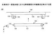
図4は、本発明の一実施形態における照明器具100の外観構成を例示する図である。なお、以下の説明において、互いに直交する3つの方向をそれぞれX方向(照明装置150の長手方向)、Y方向(照明装置150の短手方向)、Z方向(鉛直方向)とする。 FIG. 4 is a diagram illustrating the appearance configuration of theluminaire 100 according to the embodiment of the present invention. In the following description, the three directions orthogonal to each other are the X direction (longitudinal direction of the lighting device 150), the Y direction (short direction of the lighting device 150), and the Z direction (vertical direction), respectively.

図4に示す様に、照明装置150は、直管型のランプであり、照明器具本体130に取り付けられる。 As shown in FIG. 4, theluminaire 150 is a straight tube type lamp and is attached to the luminairemain body 130.

照明器具本体130は、例えば部屋の天井等に設けられる。照明器具本体130は、天井等に取り付けられる本体135、照明装置150の端部がそれぞれ装着される第1ソケット131及び第2ソケット133を有する。第1ソケット131は、照明装置150に給電する給電端子132を有する。また、第2ソケット133は、照明装置150に給電する給電端子134を有する。照明器具本体130は、第1ソケット131及び第2ソケット133に両端部が装着される照明装置150に、内部に設けられている電源供給部から給電端子132,134を介して電源を供給する。 The lighting fixturemain body 130 is provided, for example, on the ceiling of a room. The luminairemain body 130 has amain body 135 attached to a ceiling or the like, and afirst socket 131 and asecond socket 133 to which the ends of theluminaire 150 are mounted, respectively. Thefirst socket 131 has apower supply terminal 132 that supplies power to thelighting device 150. Further, thesecond socket 133 has apower supply terminal 134 that supplies power to thelighting device 150. The luminairemain body 130 supplies power to theluminaire 150 whose both ends are mounted on thefirst socket 131 and thesecond socket 133 from the power supply unit provided inside via thepower supply terminals 132 and 134.

照明装置150は、透光性カバー151、両端部に設けられる口金152,154、接続端子153,155、内部に不図示の光源を有する。透光性カバー151は、例えばアクリル樹脂等の樹脂材料で形成され、内部の光源を覆う様に設けられる。口金152,154は、照明器具本体130の第1ソケット131又は第2ソケット133にそれぞれ装着される。接続端子153,155は、照明装置150が照明器具本体130に取り付けられた時に、照明器具本体130の給電端子132,134に接続して電力の供給を受ける。照明装置150の内部に設けられている光源は、接続端子153,155から供給される電力により発光し、透光性カバー151を介して外部に光を照射する。 Thelighting device 150 has atranslucent cover 151, caps 152 and 154 provided at both ends,connection terminals 153 and 155, and a light source (not shown) inside. Thetranslucent cover 151 is made of a resin material such as an acrylic resin, and is provided so as to cover an internal light source. Thebases 152 and 154 are attached to thefirst socket 131 or thesecond socket 133 of the luminairemain body 130, respectively. When theluminaire 150 is attached to the luminairemain body 130, theconnection terminals 153 and 155 are connected to thepower supply terminals 132 and 134 of the luminairemain body 130 to receive electric power. The light source provided inside thelighting device 150 emits light by the electric power supplied from theconnection terminals 153 and 155, and irradiates the outside with the light through thetranslucent cover 151.

図5は、本発明の一実施形態における照明装置150の概略構成を例示する図である。照明装置150は、発光モジュールの一例として、LED素子156が実装された基板157を有し、LED素子156から外部に光を照射する。基板157には、一方の面に複数のLED素子156が照明装置150の長手方向(X方向)に沿って配列されている。基板157は、照明装置150が照明器具本体130に取り付けられた時に、LED素子156が実装された面が例えば本体135から室内に向く様に照明器具本体130に取り付けられる。なお、光源としては、例えばLED素子やEL素子等の半導体発光素子を用いることができる。また、基板157へのLED素子156の配列、数等は照明装置150の長さや径等に応じて適宜設定できる。 FIG. 5 is a diagram illustrating a schematic configuration of alighting device 150 according to an embodiment of the present invention. Thelighting device 150 has asubstrate 157 on which theLED element 156 is mounted as an example of the light emitting module, and irradiates light to the outside from theLED element 156. On one surface of thesubstrate 157, a plurality ofLED elements 156 are arranged along the longitudinal direction (X direction) of thelighting device 150. When thelighting device 150 is attached to the lighting fixturemain body 130, thesubstrate 157 is attached to the lighting fixturemain body 130 so that the surface on which theLED element 156 is mounted faces, for example, themain body 135 toward the room. As the light source, for example, a semiconductor light emitting element such as an LED element or an EL element can be used. Further, the arrangement, number, and the like of theLED elements 156 on thesubstrate 157 can be appropriately set according to the length, diameter, and the like of thelighting device 150.

また、照明装置150の内部には、位置情報送信部の一例としての位置信号送信器158と、無線通信部の一例としての無線通信器159が設けられている。位置信号送信器158は、例えばIMESのような測位信号を送出するアンテナを含む装置であり、当該照明装置150等の所定の位置情報を表す位置信号を無線端末に送信する。無線通信器159は、例えばIEEE802.15.4規格に適合する電波を送受信可能なアンテナを含む装置である。無線通信器159は、位置信号を受信した無線端末から、当該無線端末の識別情報と位置情報とを受信し、受信した識別情報と位置情報とを、無線端末の位置を管理する管理サーバへ送信する。 Further, inside thelighting device 150, aposition signal transmitter 158 as an example of a position information transmitting unit and awireless communication device 159 as an example of a wireless communication unit are provided. Theposition signal transmitter 158 is a device including an antenna for transmitting a positioning signal such as IMES, and transmits a position signal representing predetermined position information of thelighting device 150 or the like to a wireless terminal. Thewireless communication device 159 is, for example, a device including an antenna capable of transmitting and receiving radio waves conforming to the IEEE802.15.4 standard. Thewireless communication device 159 receives the identification information and the position information of the wireless terminal from the wireless terminal that has received the position signal, and transmits the received identification information and the position information to the management server that manages the position of the wireless terminal. do.

図6は、本発明の一実施形態における照明装置150の構成例を説明する図である。照明装置150は、上記した様に、内部に複数のLED素子156が配列された基板157、位置信号送信器158、無線通信器159、さらに、位置信号送信モジュール161、無線通信モジュール162を有する。位置信号送信モジュール161は、例えば位置信号送信器158による位置信号の送信を制御する送信制御部として機能する回路を有する基板である。無線通信モジュール162は、例えば無線通信器159と無線端末又は管理サーバとの間の通信を制御する無線通信制御部として機能する回路を有する基板である。位置信号送信モジュール161及び無線通信モジュール162は、LED素子156から照射される光を遮らない様に、基板157のLED素子156が設けられている面とは反対面側に設けられている。 FIG. 6 is a diagram illustrating a configuration example of thelighting device 150 according to the embodiment of the present invention. As described above, thelighting device 150 includes asubstrate 157 in which a plurality ofLED elements 156 are arranged, aposition signal transmitter 158, awireless communication device 159, a positionsignal transmission module 161 and awireless communication module 162. The positionsignal transmission module 161 is a substrate having a circuit that functions as a transmission control unit that controls transmission of a position signal by, for example, theposition signal transmitter 158. Thewireless communication module 162 is a substrate having a circuit that functions as a wireless communication control unit that controls communication between thewireless communication device 159 and a wireless terminal or a management server, for example. The positionsignal transmission module 161 and thewireless communication module 162 are provided on the side of thesubstrate 157 opposite to the surface on which theLED element 156 is provided so as not to block the light emitted from theLED element 156.

ここで、位置信号送信器158は、照明装置150の長手方向(X方向)において、基板157の最端部のLED素子156aと口金154との間の領域A1に設けられる。また、位置信号送信器158は、基板157の最端部のLED素子156bと口金152との間の領域A2に設けても良い。位置信号送信器158は、領域A1又はA2の何れかに設けることで、LED素子156が照射する光を遮ることなく、位置信号を無線端末に送信できる。位置信号送信器158は、図6に示す様に、例えば位置信号送信モジュール161の基板上に設けることができる。また、位置信号送信器158は、領域A1又はA2の範囲内に設ければ良く、例えば図7に示す様に、位置信号送信モジュール161上に設けなくても良い。この場合には、位置信号送信器158は、照明装置150内において、基板157よりもZ方向下方の透光性カバー151付近に設けることが好ましい。あるいは、図8に示す様に、位置信号送信器158を、例えば透光性カバー151の一部と一体で構成される金属部材163の基板157側の面の端部に設けても良い。位置信号送信器158は、金属部材163をアンテナのグランドとして利用できる。また、位置信号送信器158は、LED素子156の発光色又は透光性カバー151と同じ色で表面が着色されていることが好ましい。 Here, theposition signal transmitter 158 is provided in the region A1 between theLED element 156a at the end end of thesubstrate 157 and the base 154 in the longitudinal direction (X direction) of thelighting device 150. Further, theposition signal transmitter 158 may be provided in the region A2 between theLED element 156b at the end end of thesubstrate 157 and thebase 152. By providing theposition signal transmitter 158 in either the area A1 or A2, the position signal can be transmitted to the wireless terminal without blocking the light emitted by theLED element 156. As shown in FIG. 6, theposition signal transmitter 158 can be provided, for example, on the substrate of the positionsignal transmission module 161. Further, theposition signal transmitter 158 may be provided within the range of the area A1 or A2, and may not be provided on the positionsignal transmission module 161 as shown in FIG. 7, for example. In this case, theposition signal transmitter 158 is preferably provided in thelighting device 150 in the vicinity of thetranslucent cover 151 below thesubstrate 157 in the Z direction. Alternatively, as shown in FIG. 8, theposition signal transmitter 158 may be provided at the end of the surface of themetal member 163 that is integrally formed with, for example, a part of thetranslucent cover 151 on thesubstrate 157 side. Theposition signal transmitter 158 can use themetal member 163 as the ground of the antenna. Further, it is preferable that the surface of theposition signal transmitter 158 is colored in the same color as the light emitting color of theLED element 156 or thetranslucent cover 151.

無線通信器159は、位置信号送信器158と同様に領域A1又はA2の何れかに設けられる。無線通信器159は、領域A1又はA2に設けられることで、LED素子156から照射される光を遮ることなく、無線端末及び管理サーバとの間で位置情報及び識別情報を通信できる。なお、位置信号送信器158と無線通信器159とは、領域A1又はA2の何れか一方の同じ領域に設置しても良く、反対側の領域にそれぞれ設置しても良い。また、無線通信器159は、LED素子156の発光色又は透光性カバー151と同じ色で表面が着色されていることが好ましい。 Theradio communication device 159 is provided in either the area A1 or A2 like theposition signal transmitter 158. By providing thewireless communication device 159 in the area A1 or A2, the position information and the identification information can be communicated between the wireless terminal and the management server without blocking the light emitted from theLED element 156. Theposition signal transmitter 158 and thewireless communication device 159 may be installed in the same area of either one of the areas A1 and A2, or may be installed in the opposite area. Further, it is preferable that the surface of thewireless communication device 159 is colored with the same color as the light emitting color of theLED element 156 or thetranslucent cover 151.

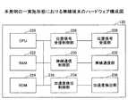
図9は、本発明の一実施形態における照明器具100のハードウェア構成である。照明装置150は、CPU200、RAM202、ROM204、位置信号送信制御部206、位置信号送信部208、無線通信制御部210、無線通信部212、電圧変換部214、発光部215、電源制御部216、バス217を有する。 FIG. 9 is a hardware configuration of theluminaire 100 according to the embodiment of the present invention. Thelighting device 150 includes aCPU 200, aRAM 202, aROM 204, a position signaltransmission control unit 206, a positionsignal transmission unit 208, a wirelesscommunication control unit 210, awireless communication unit 212, avoltage conversion unit 214, alight emitting unit 215, a powersupply control unit 216, and a bus. It has 217.

CPU200は、当該照明装置150における通信等の動作制御を行うプログラムを実行する。RAM202は、CPU200のワークエリア等を構成する。ROM204は、CPU200が実行するプログラムに加えて、当該照明器具100の位置情報を記憶する。位置信号送信制御部206は、位置信号送信部208を介して当該照明器具100の位置情報を表す測位信号を送信するための処理を実行する。位置信号送信部208は、照明装置150が備える位置信号送信器158である。無線通信制御部210は、無線通信部212を介して無線通信処理を実行する。無線通信部212は、照明装置150が備える無線通信器159である。電圧変換部214は、例えばDC/DCコンバータであり、電源制御部216から供給される電源の電圧を、位置信号送信部208、無線通信器212を動作させるための電圧に変換する。発光部215は、図5に示す照明装置150のLED素子156が設けられた基板157である。また電源制御部216は、例えば平滑回路及び電流監視回路であり、供給される電源を、発光部215を動作させるのに適したものに変換する。バス217は、上記各部を電気的に接続する。 TheCPU 200 executes a program that controls operations such as communication in thelighting device 150. TheRAM 202 constitutes a work area or the like of theCPU 200. TheROM 204 stores the position information of theluminaire 100 in addition to the program executed by theCPU 200. The position signaltransmission control unit 206 executes a process for transmitting a positioning signal representing the position information of thelighting fixture 100 via the positionsignal transmission unit 208. Theposition signal transmitter 208 is aposition signal transmitter 158 included in thelighting device 150. The wirelesscommunication control unit 210 executes wireless communication processing via thewireless communication unit 212. Thewireless communication unit 212 is awireless communication device 159 included in thelighting device 150. Thevoltage conversion unit 214 is, for example, a DC / DC converter, and converts the voltage of the power supply supplied from the powersupply control unit 216 into a voltage for operating the positionsignal transmission unit 208 and thewireless communication device 212. Thelight emitting unit 215 is asubstrate 157 provided with theLED element 156 of thelighting device 150 shown in FIG. Further, the powersupply control unit 216 is, for example, a smoothing circuit and a current monitoring circuit, and converts the supplied power supply into one suitable for operating thelight emitting unit 215.Bus 217 electrically connects the above parts.

上記構成により、本発明の一実施形態における照明器具100の照明装置150は、無線端末120に対して位置情報を送信し、無線端末120から識別情報と位置情報を受信し、これらの情報を管理装置を介して管理サーバへ送信することができる。なお、照明器具100は、例えば非常口等に設けられる非常灯であっても良い。また、上述したように、位置情報を無線通信制御部210と無線通信部212によって送信する場合には、位置信号送信制御部206と位置信号送信器208は不要となる。 With the above configuration, thelighting device 150 of thelighting fixture 100 according to the embodiment of the present invention transmits position information to thewireless terminal 120, receives identification information and position information from thewireless terminal 120, and manages these information. It can be sent to the management server via the device. Thelighting fixture 100 may be, for example, an emergency light provided at an emergency exit or the like. Further, as described above, when the position information is transmitted by the wirelesscommunication control unit 210 and thewireless communication unit 212, the position signaltransmission control unit 206 and theposition signal transmitter 208 are unnecessary.

また、図10は、本発明の一実施形態における照明装置150の駆動回路の概略ブロック図である。図10に示す様に、照明装置150の駆動回路は、第1電源入力部290、第2電源入力部294、駆動部298を有する。 Further, FIG. 10 is a schematic block diagram of a drive circuit of thelighting device 150 according to the embodiment of the present invention. As shown in FIG. 10, the drive circuit of thelighting device 150 includes a firstpower input unit 290, a secondpower input unit 294, and adrive unit 298.

第1電源入力部290は、接続端子153に接続し、照明器具本体130のソケット131の給電端子132から安定器を介して電源が供給され、電源のノイズを除去して平滑化した上で直流化して駆動部298に直流電源を供給する。第2電源入力部294は、接続端子155に接続し、照明器具本体130のソケット133の給電端子134から安定器を介して電源が供給され、電源のノイズを除去して平滑化した上で直流化して駆動部298に直流電源を供給する。照明装置150は、第1電源入力部290と第2電源入力部294の何れか一方の電源入力部から電源を供給されることができ、両方の電源入力部が同時に電源を供給されることもできる。 The firstpower input unit 290 is connected to theconnection terminal 153, and power is supplied from thepower supply terminal 132 of thesocket 131 of the luminairemain body 130 via a ballast to remove noise from the power supply, smooth it, and then direct current. The DC power supply is supplied to thedrive unit 298. The secondpower input unit 294 is connected to theconnection terminal 155, and power is supplied from thepower supply terminal 134 of thesocket 133 of the luminairemain body 130 via a ballast to remove noise from the power supply, smooth it, and then direct current. The DC power supply is supplied to thedrive unit 298. Thelighting device 150 can be supplied with power from either one of the firstpower input unit 290 and the secondpower input unit 294, and both power input units may be supplied with power at the same time. can.

第1電源入力部290及び第2電源入力部294は、それぞれ保護部291,295、ノイズ除去部292,296、平滑部293,297を有する。保護部291,295は、異常電源の入力を防止することで、駆動部298及び発光部215を保護する。ノイズ除去部292,296は、供給される電源に外部から流入されるサージ及びノイズを除去して出力する。平滑部293,296は、ノイズ除去部292,296から入力される電源を平滑化し直流化して駆動部298に供給する。 The firstpower input unit 290 and the secondpower input unit 294 have a protection unit 291,295, a noise removal unit 292,296, and a smoothing unit 293,297, respectively. The protection units 291,295 protect thedrive unit 298 and thelight emitting unit 215 by preventing the input of the abnormal power supply. Thenoise removing units 292 and 296 remove surges and noises that flow into the supplied power supply from the outside and output the noise. The smoothingunits 293 and 296 smooth the power input input from thenoise removing units 292 and 296, convert it into direct current, and supply it to thedrive unit 298.

駆動部298は、平滑部293,297の出力電源を昇圧又は降圧し、常に一定の大きさの電流を発光部215に供給する。 Thedrive unit 298 boosts or lowers the output power supply of the smoothingunits 293 and 297, and constantly supplies a constant magnitude of current to thelight emitting unit 215.

照明装置150は、例えば上記した構成により、接続端子153,155の何れか一方から電源が入力された場合にも、他方から電源が流出しないため、接触による電気事故を防止し、特別な電源工事を必要とせずに安全に取り付けることができる。また、入力される電源からノイズ等を遮断することで発光部215を保護し、安定した照明機能を提供できる。 With the above configuration, for example, thelighting device 150 prevents electrical accidents due to contact even when power is input from either one of theconnection terminals 153 and 155, so that the power does not flow out from the other, and special power supply work is performed. Can be installed safely without the need for. Further, by blocking noise and the like from the input power supply, thelight emitting unit 215 can be protected and a stable lighting function can be provided.

図11は、本発明の一実施形態における無線端末120のハードウェア構成を表す。通信端末120は、CPU220、RAM222、ROM224、位置信号受信制御部226、位置信号受信部228、無線通信制御部230、無線通信部232、加速度検出制御部234、加速度検出部236及びバス238を有する。 FIG. 11 shows the hardware configuration of thewireless terminal 120 according to the embodiment of the present invention. Thecommunication terminal 120 includes aCPU 220, aRAM 222, aROM 224, a position signalreception control unit 226, a positionsignal reception unit 228, a wirelesscommunication control unit 230, awireless communication unit 232, an accelerationdetection control unit 234, anacceleration detection unit 236, and abus 238. ..

CPU220は、当該無線端末120の動作制御を行うプログラムを実行する。RAM222は、CPU220のワークエリア等を構成する。ROM224は、CPU220が実行するプログラムに加えて、当該無線端末120の識別情報や、照明器具100から受信した位置情報を記憶する。位置信号受信制御部226は、位置信号受信部228を介して、位置情報を表す測位信号を受信するための処理を実行する。位置信号受信部228は、例えばIMESのような測位信号を受信するアンテナを含む装置である。無線通信制御部230は、無線通信部232を介して無線通信処理を実行する。無線通信部232は、例えばIEEE802.15.4規格に適合する電波を送受信可能なアンテナを含む装置である。加速度検出制御部234は、加速度検出部236を介して加速度の変化を検出する。加速度検出部236は、例えば加速度センサ又は慣性力や磁気を用いたモーションセンサである。バス238は、上記各部を電気的に接続する。 TheCPU 220 executes a program that controls the operation of thewireless terminal 120. TheRAM 222 constitutes a work area or the like of theCPU 220. TheROM 224 stores the identification information of thewireless terminal 120 and the position information received from thelighting fixture 100 in addition to the program executed by theCPU 220. The position signalreception control unit 226 executes a process for receiving a positioning signal representing position information via the positionsignal reception unit 228. The positionsignal receiving unit 228 is a device including an antenna for receiving a positioning signal such as IMES. The wirelesscommunication control unit 230 executes wireless communication processing via thewireless communication unit 232. Thewireless communication unit 232 is, for example, a device including an antenna capable of transmitting and receiving radio waves conforming to the IEEE802.15.4 standard. The accelerationdetection control unit 234 detects a change in acceleration via theacceleration detection unit 236. Theacceleration detection unit 236 is, for example, an acceleration sensor or a motion sensor using inertial force or magnetism. Thebus 238 electrically connects the above parts.

上記構成により、本発明の一実施形態における無線端末120は、照明器具100から位置情報を受信し、前記位置情報と共に自らの識別情報を照明器具100へ送信することができる。特に、無線端末が動かされたタイミングで送信又は受信の動作を行うことにより、効率的に識別情報及び位置情報を送信することができる。 With the above configuration, thewireless terminal 120 according to the embodiment of the present invention can receive the position information from thelighting equipment 100 and transmit its own identification information to thelighting equipment 100 together with the position information. In particular, the identification information and the position information can be efficiently transmitted by performing the transmission or reception operation at the timing when the wireless terminal is moved.

なお、無線端末120がスマートフォンやPCのような情報端末である場合には、ユーザからの入力を受け付ける、例えばタッチパネル、ダイヤルキー、キーボード、マウスのような入力装置及び対応する入力制御部を備えてもよい。さらに、スクリーンのような表示装置及び対応する表示制御部を備えてもよい。 When thewireless terminal 120 is an information terminal such as a smartphone or a PC, it is provided with an input device such as a touch panel, a dial key, a keyboard, a mouse, and a corresponding input control unit that accepts input from the user. May be good. Further, a display device such as a screen and a corresponding display control unit may be provided.

また、無線端末120がGPSアンテナ及び対応する制御部を備える場合には、前記アンテナを用いてIMESによる測位信号を受信でき、ソフトウェアの改修のみによって当該位置情報管理システム1に対応させることができる。 Further, when thewireless terminal 120 is provided with a GPS antenna and a corresponding control unit, the positioning signal by IMES can be received by using the antenna, and the positioninformation management system 1 can be made compatible only by modifying the software.

また、加速度検出制御部234及び加速度検出部236は任意の構成要素である。加速度検出制御部234及び加速度検出部236を備えない場合には、当該無線端末120の送信又は受信の動作は、予め定められた間隔又は時刻においてなされる。 Further, the accelerationdetection control unit 234 and theacceleration detection unit 236 are arbitrary components. When the accelerationdetection control unit 234 and theacceleration detection unit 236 are not provided, the transmission or reception operation of thewireless terminal 120 is performed at a predetermined interval or time.

また、上述したように、位置情報が無線通信制御部230と無線通信部232によって受信される場合には、位置信号受信制御部226と位置信号受信部228は不要となる。 Further, as described above, when the position information is received by the wirelesscommunication control unit 230 and thewireless communication unit 232, the position signalreception control unit 226 and the positionsignal reception unit 228 are unnecessary.

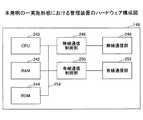
図12は、本発明の一実施形態における管理装置140のハードウェア構成を表す。管理装置140は、CPU240、RAM242、ROM244、無線通信制御部246、無線通信部248、有線通信制御部250、有線通信部252及びバス254を有する。 FIG. 12 shows the hardware configuration of themanagement device 140 according to the embodiment of the present invention. Themanagement device 140 includes aCPU 240, aRAM 242, aROM 244, a wirelesscommunication control unit 246, awireless communication unit 248, a wiredcommunication control unit 250, awired communication unit 252, and abus 254.

CPU240は、当該管理装置140の動作制御を行うプログラムを実行する。RAM242は、CPU240のワークエリア等を構成する。ROM244は、CPU240が実行するプログラムや該プログラムが使用するデータを記憶する。無線通信制御部246は、無線通信部248を介して無線通信処理を実行する。無線通信部248は、例えばIEEE802.15.4規格に適合する電波を送受信可能なアンテナを含む装置である。有線通信制御部250は、有線通信部252を介して有線による通信処理を実行する。有線通信部252は、例えばIEEE802.3規格に適合するネットワークインターフェースを有する装置である。バス254は、上記各部を電気的に接続する。 TheCPU 240 executes a program that controls the operation of themanagement device 140. TheRAM 242 constitutes a work area or the like of theCPU 240. TheROM 244 stores a program executed by theCPU 240 and data used by the program. The wirelesscommunication control unit 246 executes wireless communication processing via thewireless communication unit 248. Thewireless communication unit 248 is, for example, a device including an antenna capable of transmitting and receiving radio waves conforming to the IEEE802.15.4 standard. The wiredcommunication control unit 250 executes a wired communication process via the wiredcommunication unit 252. Thewired communication unit 252 is, for example, a device having a network interface conforming to the IEEE802.3 standard. Thebus 254 electrically connects the above parts.

上記構成により、本発明の一実施形態における管理装置140は、照明器具100及び無線端末120を含むネットワーク180からの信号を、管理サーバ160を含むネットワーク190へと変換することができる。また、PANを構成するネットワーク180がZigBee(登録商標)である場合には、PANに参加するデバイスを管理するコーディネータの機能を有することができる。 With the above configuration, themanagement device 140 according to the embodiment of the present invention can convert a signal from thenetwork 180 including thelighting equipment 100 and thewireless terminal 120 into thenetwork 190 including themanagement server 160. Further, when thenetwork 180 constituting the PAN is ZigBee (registered trademark), it can have a function of a coordinator for managing the devices participating in the PAN.

図13は、本発明の一実施形態における管理サーバ160のハードウェア構成を表す。管理サーバ160は、CPU260、RAM262、ROM264、HDD266、通信制御部268、通信部270、表示制御部272、表示部274、入力制御部276、入力部278及びバス280を有する。 FIG. 13 shows the hardware configuration of themanagement server 160 according to the embodiment of the present invention. Themanagement server 160 includes aCPU 260, aRAM 262, aROM 264, anHDD 266, acommunication control unit 268, acommunication unit 270, adisplay control unit 272, adisplay unit 274, aninput control unit 276, aninput unit 278, and abus 280.

CPU260は、当該管理サーバ160の動作制御を行うプログラムを実行する。RAM262は、CPU260のワークエリア等を構成する。ROM264は、CPU260が実行するプログラムや該プログラムが使用するデータを記憶する。HDD266は、当該位置情報管理システム1で用いられる無線端末120の位置を管理するための情報を記憶する。通信制御部268は、通信部270を介して通信処理を実行する。通信部270は、例えばIEEE802.3規格に適合するネットワークインターフェースを有する装置である。表示制御部272は、当該管理サーバ160上で実行される、位置管理に係るプログラムの処理内容に合わせて、表示部274に表示される内容を制御する。表示部274は、例えば液晶ディスプレイやCRTディスプレイのようなディスプレイが含まれる。入力制御部276は、ユーザからの入力を受け付ける、キーボード、マウス等の入力部278からの信号を処理する。バス280は、上記各部を電気的に接続する。 TheCPU 260 executes a program that controls the operation of themanagement server 160. TheRAM 262 constitutes a work area or the like of theCPU 260. TheROM 264 stores a program executed by theCPU 260 and data used by the program. TheHDD 266 stores information for managing the position of thewireless terminal 120 used in the positioninformation management system 1. Thecommunication control unit 268 executes the communication process via thecommunication unit 270. Thecommunication unit 270 is, for example, a device having a network interface conforming to the IEEE802.3 standard. Thedisplay control unit 272 controls the content displayed on thedisplay unit 274 according to the processing content of the program related to the position management executed on themanagement server 160. Thedisplay unit 274 includes a display such as a liquid crystal display or a CRT display. Theinput control unit 276 processes a signal from theinput unit 278 of the keyboard, mouse, or the like that receives the input from the user. Thebus 280 electrically connects the above parts.

上記構成により、本発明の一実施形態における管理サーバ160は、無線端末120の位置を管理し、該無線端末120の所在を探索することができる。 With the above configuration, themanagement server 160 according to the embodiment of the present invention can manage the position of thewireless terminal 120 and search for the location of thewireless terminal 120.

なお、HDD266は、テープドライブを含むあらゆる記憶装置であってもよく、あるいは、ネットワークを介してアクセス可能なストレージ領域であってもよい。 TheHDD 266 may be any storage device including a tape drive, or may be a storage area accessible via a network.

また、管理サーバ160は、上述した管理装置140が備える無線通信制御部及び無線通信装置を備え、管理装置140に代えて、その処理を行ってもよい。これにより、管理装置140を別途設ける必要がなくなる。
(3.機能)
図14は、本発明の一実施形態における照明器具100の機能ブロック図を表す。本発明の一実施形態における照明器具100の照明装置150は、記憶手段300、通信手段304及び制御手段312を有する。
Further, themanagement server 160 includes a wireless communication control unit and a wireless communication device included in themanagement device 140 described above, and may perform the processing in place of themanagement device 140. This eliminates the need to separately provide themanagement device 140.
(3. Function)
FIG. 14 shows a functional block diagram of theluminaire 100 according to the embodiment of the present invention. The illuminatingdevice 150 of theluminaire 100 according to the embodiment of the present invention includes a storage means 300, a communication means 304, and a control means 312.

記憶手段300は、照明装置150の位置情報302を記憶する。位置情報302を記憶するためのテーブルの例を図18に示す。図18は、階数、緯度、経度、棟番号の項目を含む。階数は、照明装置150が設置される建物の階数を表す。緯度及び経度は、照明装置150の所在する位置の緯度及び経度を表す。棟番号は、照明装置150が設置される建物の棟番号を表す。図18の例では、照明装置150は、ある建物のC棟の16階に所在し、緯度が35.459555、経度が139.387110の地点に所在する。 The storage means 300 stores theposition information 302 of thelighting device 150. An example of a table for storing theposition information 302 is shown in FIG. FIG. 18 includes items of floor number, latitude, longitude, and building number. The number of floors represents the number of floors of the building in which thelighting device 150 is installed. The latitude and longitude represent the latitude and longitude of the position where thelighting device 150 is located. The ridge number represents the ridge number of the building in which thelighting device 150 is installed. In the example of FIG. 18, thelighting device 150 is located on the 16th floor of Building C of a certain building, at a latitude of 35.459555 and a longitude of 139.387110.

通信手段304は、位置情報送信手段306、端末情報受信手段308及び端末情報送信手段310を有する。 The communication means 304 includes a position information transmitting means 306, a terminal information receiving means 308, and a terminalinformation transmitting means 310.

位置情報送信手段306は、経緯情報、建物の階数、棟番号のような情報を含む位置情報302を、所定の範囲にある無線端末120に対して連続的又は断続的に無線送信する。位置情報302は、例えばIMESに規定されるフォーマットを用いて送信される。位置情報送信手段306は、例えば照明装置150が備える位置信号送信器158である。 The position information transmitting means 306 wirelessly transmits theposition information 302 including information such as background information, the number of floors of the building, and the building number to thewireless terminal 120 within a predetermined range continuously or intermittently. Theposition information 302 is transmitted using, for example, a format specified in IMES. The position information transmitting means 306 is, for example, aposition signal transmitter 158 included in thelighting device 150.

端末情報受信手段308は、無線端末120から送信された識別情報と位置情報とを受信する。端末情報送信手段310は、無線端末120から送信された識別情報と位置情報とを、管理装置140を介して管理サーバ160へ送信する。ネットワーク180がZigBee(登録商標)規格を用いてなされる場合には、前記送信は、当該照明装置150が保持するルーティング情報を用いて行われる。端末情報受信手段308及び端末情報送信手段310は、例えば照明装置150が備える無線通信器159である。 The terminal information receiving means 308 receives the identification information and the position information transmitted from thewireless terminal 120. The terminal information transmitting means 310 transmits the identification information and the position information transmitted from thewireless terminal 120 to themanagement server 160 via themanagement device 140. When thenetwork 180 is made using the ZigBee® standard, the transmission is made using the routing information held by theilluminator 150. The terminal information receiving means 308 and the terminal information transmitting means 310 are, for example, awireless communication device 159 included in thelighting device 150.

制御手段312は、照明装置150の動作を制御する。照明装置150が無線端末120及び管理装置140とZigBee(登録商標)を用いてPANを構成する場合には、照明装置150がルータ機能を提供するよう制御する。 The control means 312 controls the operation of thelighting device 150. When thelighting device 150 constitutes a PAN by using thewireless terminal 120, themanagement device 140, and ZigBee (registered trademark), thelighting device 150 is controlled to provide a router function.

上記構成により、本発明の一実施形態における照明器具100は、位置情報302を保持し、位置情報302を無線端末120に送信し、該無線端末120の識別情報と位置情報を受信して、該識別情報を管理装置140を通じて管理サーバへ送信することができる。 According to the above configuration, thelighting fixture 100 according to the embodiment of the present invention holds theposition information 302, transmits theposition information 302 to thewireless terminal 120, receives the identification information and the position information of thewireless terminal 120, and receives the position information. The identification information can be transmitted to the management server through themanagement device 140.

なお、位置情報302は、照明装置150の経緯座標、照明装置150が配置される建物のフロア情報及び照明装置150が配置される建物情報のうち少なくとも1つ以上を含んで構成される。また、位置情報302は、建物情報として、照明装置150が設置される建物名や、部屋の中の区画を表す情報のような追加の情報を含んでもよい。これにより、より細かな位置管理が可能となる。 Theposition information 302 includes at least one or more of the longitudinal coordinates of thelighting device 150, the floor information of the building in which thelighting device 150 is arranged, and the building information in which thelighting device 150 is arranged. Further, theposition information 302 may include additional information such as the name of the building where thelighting device 150 is installed and the information indicating the section in the room as the building information. This enables finer position management.

図15は、本発明の一実施形態における無線端末120の機能ブロック図を表す。本発明の一実施形態における無線端末120は、記憶手段320、通信手段326、加速度検出手段332及び制御手段334を有する。 FIG. 15 shows a functional block diagram of thewireless terminal 120 according to the embodiment of the present invention. Thewireless terminal 120 according to the embodiment of the present invention includes a storage means 320, a communication means 326, an acceleration detection means 332, and a control means 334.

記憶手段320は、識別情報322と位置情報324を有する。識別情報322は、当該無線端末120のネットワークアドレスのような、当該位置情報管理システム1上で無線端末120を特定可能な情報を含む。例えば、ネットワーク180がIEEE802.15.4及びZigBee(登録商標)規格に基づく場合には、IEEE802.15.4の短縮アドレス又はIEEE拡張(MAC)アドレスを用いることができる。位置情報324は、照明器具100から送信された位置情報302である。位置情報324を記憶するためのテーブルの例を図19に示す。構成は図18と同様である。 The storage means 320 hasidentification information 322 andposition information 324. Theidentification information 322 includes information that can identify thewireless terminal 120 on the locationinformation management system 1, such as the network address of thewireless terminal 120. For example, if thenetwork 180 is based on the IEEE 802.15.4 and ZigBee® standards, an IEEE 802.15.4 abbreviated address or an IEEE extended (MAC) address can be used. Theposition information 324 is theposition information 302 transmitted from theluminaire 100. An example of a table for storing theposition information 324 is shown in FIG. The configuration is the same as in FIG.

通信手段326は、位置情報受信手段328と識別情報送信手段330を有する。 The communication means 326 has a position information receiving means 328 and an identification information transmitting means 330.

位置情報受信手段328は、照明器具100から送信された位置情報302を受信する。受信された位置情報302は、当該無線端末120の記憶手段320に保持される。 The position information receiving means 328 receives theposition information 302 transmitted from thelighting fixture 100. The receivedposition information 302 is held in the storage means 320 of thewireless terminal 120.

識別情報送信手段330は、当該無線端末120の識別情報322と共に位置情報324を照明器具100に送信する。位置情報324は、例えば図20のようなフォーマットにより照明器具100に送信される。図20のフォーマットでは、階数、緯度、経度、棟番号の各フィールドが、それぞれ9ビット、21ビット、21ビット、8ビットで表現され、IMES規格によって受信したメッセージの該当フィールドを繋げた形とする。各フィールドの表現形式はIMES規格に準ずる。実際には、このフォーマットに加えて、通信方式によって規定されるヘッダやチェックサム情報が付加されて送信される。通信方式として、例えばIEEE802.15.4及びZigBee(登録商標)規格が用いられる。 The identification information transmitting means 330 transmits theposition information 324 to thelighting equipment 100 together with theidentification information 322 of thewireless terminal 120. Theposition information 324 is transmitted to theluminaire 100 in the format shown in FIG. 20, for example. In the format of FIG. 20, each field of floor number, latitude, longitude, and building number is represented by 9 bits, 21 bits, 21 bits, and 8 bits, respectively, and the corresponding fields of the message received according to the IMES standard are connected. .. The representation format of each field conforms to the IMES standard. Actually, in addition to this format, the header and checksum information specified by the communication method are added and transmitted. As the communication method, for example, IEEE802.15.4 and ZigBee® standard are used.

加速度検出手段332は、当該無線端末120の加速度の変化を検出する。加速度の変化は、例えば当該無線端末120が移動を開始した時、該移動が停止した時、又は傾きを検出した時等に検出される。検出された加速度の変化は、当該無線端末120の送信又は受信の動作のタイミングを決定するために用いられる。なお、当該加速度検出手段332は任意の構成要素である。 The acceleration detecting means 332 detects a change in the acceleration of thewireless terminal 120. The change in acceleration is detected, for example, when thewireless terminal 120 starts moving, when the movement stops, or when a tilt is detected. The detected change in acceleration is used to determine the timing of the transmission or reception operation of thewireless terminal 120. The acceleration detecting means 332 is an arbitrary component.

制御手段334は、位置情報受信手段328による位置情報の受信のタイミングと、識別情報送信手段330による識別情報322と位置情報324との送信のタイミングを制御する。送受信のタイミングは、加速度検出手段332による加速度の変化の検出に基づいて決定される。あるいは、当該無線端末120に予め設定された間隔あるいは時刻に基づいて決定されてもよい。また、送信と受信のタイミングは、それぞれ独立して決定されてもよい。さらに、制御手段334は、当該無線端末120が照明器具100及び管理装置140と共にZigBee(登録商標)によりPANを構成する場合には、当該無線端末120がエンドポイント機能を提供するよう制御する。 The control means 334 controls the timing of receiving the position information by the position information receiving means 328 and the timing of transmitting theidentification information 322 and theposition information 324 by the identification information transmitting means 330. The transmission / reception timing is determined based on the detection of the change in acceleration by theacceleration detecting means 332. Alternatively, it may be determined based on a preset interval or time in thewireless terminal 120. Further, the transmission and reception timings may be determined independently of each other. Further, the control means 334 controls thewireless terminal 120 to provide the endpoint function when thewireless terminal 120 constitutes a PAN by ZigBee (registered trademark) together with thelighting equipment 100 and themanagement device 140.

上記構成により、本発明の一実施形態における無線端末120は、照明装置から位置情報を効率的に受信し、該位置情報と共に識別情報通信装置へ効率的に送信することができる。 With the above configuration, thewireless terminal 120 according to the embodiment of the present invention can efficiently receive the position information from the lighting device and efficiently transmit the position information together with the position information to the identification information communication device.

なお、無線端末120がスマートフォンやPCのような情報端末である場合には、ユーザからの入力を受け付ける入力手段や、ユーザに情報を提示する表示手段を備えてもよい。これにより、ユーザへの識別情報又は位置情報の提示や、ユーザからの識別情報又は位置情報の入力又は修正が可能となる。 When thewireless terminal 120 is an information terminal such as a smartphone or a PC, it may be provided with an input means for receiving input from the user and a display means for presenting information to the user. This makes it possible to present the identification information or the location information to the user, and to input or modify the identification information or the location information from the user.

図16は、本発明の一実施形態における管理装置140の機能ブロック図を表す。本発明の一実施形態における管理装置140は、通信手段340、変換手段346及び制御手段348を有する。 FIG. 16 shows a functional block diagram of themanagement device 140 according to the embodiment of the present invention. Themanagement device 140 in one embodiment of the present invention includes communication means 340, conversion means 346, and control means 348.

通信手段340は、受信手段342と送信手段344を有する。受信手段342は、ネットワーク180に属する照明装置又は無線端末から送信されたデータを受信する。送信手段344は、当該管理装置140で変換された前記データを、ネットワーク190に属する管理サーバ160へ送信する。ネットワーク180は、例えばIEEE802.15.4及びZigBee(登録商標)規格に基づくPANである。また、ネットワーク190は、例えばIEEE802.3規格に基づくLANである。 The communication means 340 includes a receiving means 342 and a transmitting means 344. The receiving means 342 receives the data transmitted from the lighting device or the wireless terminal belonging to thenetwork 180. The transmission means 344 transmits the data converted by themanagement device 140 to themanagement server 160 belonging to thenetwork 190.Network 180 is, for example, a PAN based on IEEE 802.15.4 and ZigBee® standards. Thenetwork 190 is, for example, a LAN based on the IEEE802.3 standard.

変換手段346は、受信手段342がネットワーク180から受信したデータを、ネットワーク190に適合する形式に変換する。変換されたデータは、送信手段344によって、ネットワーク190を介して管理サーバ160へ送信される。ここで、前記データに含まれる、無線端末120の識別情報が、IEEE802.15.4の短縮アドレスで表されている場合には、PAN構成時の情報に基づき、IEEE拡張アドレスに変換される。 The conversion means 346 converts the data received by the receiving means 342 from thenetwork 180 into a format suitable for thenetwork 190. The converted data is transmitted to themanagement server 160 via thenetwork 190 by the transmission means 344. Here, when the identification information of thewireless terminal 120 included in the data is represented by the abbreviated address of IEEE802.15.4, it is converted into the IEEE extended address based on the information at the time of PAN configuration.

制御手段348は、当該管理装置140の動作を制御する。当該管理装置140が照明器具100と無線端末120と共にZigBee(登録商標)規格によりPANを構成する場合には、当該管理装置140がコーディネータ機能を提供するよう制御する。 The control means 348 controls the operation of themanagement device 140. When themanagement device 140 constitutes a PAN together with theluminaire 100 and thewireless terminal 120 according to the ZigBee (registered trademark) standard, themanagement device 140 is controlled to provide a coordinator function.

上記構成により、本発明の一実施形態における管理装置140は、照明器具100及び無線端末120が属するネットワーク180と、管理サーバが属するネットワーク190との間の通信をブリッジすることができる。 With the above configuration, themanagement device 140 according to the embodiment of the present invention can bridge the communication between thenetwork 180 to which thelighting fixture 100 and thewireless terminal 120 belong and thenetwork 190 to which the management server belongs.

図17は、本発明の一実施形態における管理サーバ160の機能ブロック図を表す。本発明の一実施形態における管理サーバ160は、通信手段360、記憶手段366、入力手段370、表示手段372及び制御手段374を有する。 FIG. 17 shows a functional block diagram of themanagement server 160 according to the embodiment of the present invention. Themanagement server 160 in one embodiment of the present invention includes communication means 360, storage means 366, input means 370, display means 372, and control means 374.

通信手段360は、受信手段362と送信手段364を有する。受信手段362は、管理装置140を通じて無線端末から送信された識別情報と位置情報とを受信する。受信された識別情報と位置情報は、記憶手段366に記憶される。送信手段364は、外部サーバ等に対して位置情報の提供を求められた場合に、該位置情報を前記外部サーバ等に送信する。 The communication means 360 includes a receiving means 362 and a transmitting means 364. The receiving means 362 receives the identification information and the position information transmitted from the wireless terminal through themanagement device 140. The received identification information and position information are stored in the storage means 366. When the transmission means 364 is requested to provide the location information to the external server or the like, the transmission means 364 transmits the location information to the external server or the like.

記憶手段366は、位置管理情報368を有する。位置管理情報368は、無線端末120から受信した識別情報と位置情報に、受信時刻等の管理情報を付加した情報である。該情報を記憶するテーブルの例を図21に示す。図21は、識別情報、機器名、所有部署、緯度、経度、階数、棟、受信日時の項目を有する。識別情報は、当該識別情報を送信した無線端末120の、例えばIEEE拡張アドレスのような情報である。緯度、経度、階数、棟は、識別情報と共に受信された位置情報に対応する。受信日時は、管理サーバ160が当該情報を受信した日時である。機器名は、当該情報を送信した無線端末120が付される管理対象の名前又は無線端末120の機器名である。所有部署は、当該情報を送信した無線端末120を所有する部署名である。機器名及び所有部署の情報は、予め当該管理サーバ160によって、識別情報と関連付けられている。 The storage means 366 hasposition management information 368. Theposition management information 368 is information obtained by adding management information such as a reception time to the identification information and the position information received from thewireless terminal 120. An example of a table that stores the information is shown in FIG. FIG. 21 has items of identification information, device name, owning department, latitude, longitude, number of floors, building, reception date and time. The identification information is information such as an IEEE extended address of thewireless terminal 120 that has transmitted the identification information. Latitude, longitude, number of floors, and ridge correspond to the location information received along with the identification information. The reception date and time is the date and time when themanagement server 160 received the information. The device name is the name of the management target to which thewireless terminal 120 that transmitted the information is attached or the device name of thewireless terminal 120. The owning department is the name of the department that owns thewireless terminal 120 that transmitted the information. The device name and the information of the owning department are previously associated with the identification information by themanagement server 160.

入力手段370は、ユーザが位置情報を探索するために、ユーザからの入力を受け付ける。 The input means 370 accepts input from the user in order for the user to search for position information.

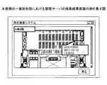
表示手段372は、ユーザが位置情報を探索するための検索画面に係るGUIを画面上に表示する。検索画面の例を図23に示す。図23に示された「所在検索システム」では、記憶手段366に記憶された情報を元に、無線端末に係る所有部署と機器名を画面に一覧表示する。ユーザが、検索したい機器のチェックボックスを入力手段370を通じて選択すると、チェックマークが付される。検索したい機器に全てチェックマークを付けた後に「検索実行」ボタンを選択すると、検索が実行され、結果を表示する画面に切り替わる。図23の例では、ユーザが「営業1課」が所有する「UCS P3000」という機器を対象として検索を実行する例を示している。図24は、その検索結果の画面の例である。「検索実行」ボタンが選択されると、表示手段372は、記憶手段366に記憶されたデータを元に、「UCS P3000」が所在する「A棟4階」のフロア図と、その機器名及び受信日時を表示する。 The display means 372 displays a GUI related to a search screen for the user to search for position information on the screen. An example of the search screen is shown in FIG. In the "location search system" shown in FIG. 23, the owned department and the device name related to the wireless terminal are listed on the screen based on the information stored in the storage means 366. When the user selects the check box of the device to be searched through the input means 370, a check mark is added. If you select the "Execute Search" button after checking all the devices you want to search, the search will be executed and the screen will switch to the screen that displays the results. In the example of FIG. 23, an example is shown in which a user executes a search for a device called “UCS P3000” owned by “Sales Section 1”. FIG. 24 is an example of the search result screen. When the "Search execution" button is selected, the display means 372 sets the floor diagram of the "Building A 4th floor" where the "UCS P3000" is located, its device name, and the device name based on the data stored in the storage means 366. Display the reception date and time.

制御手段374は、当該管理サーバの動作を制御する。 The control means 374 controls the operation of the management server.

上記構成により、本発明の一実施形態における管理サーバ160は、無線端末の位置を管理し、その所在を検索することができる。特に、無線端末の位置そのものを表す情報そのものを直接受信して管理することができ、位置の探索にかかる計算量を低減することができる。 With the above configuration, themanagement server 160 according to the embodiment of the present invention can manage the position of the wireless terminal and search for the location of the wireless terminal. In particular, the information itself representing the position of the wireless terminal itself can be directly received and managed, and the amount of calculation required for searching for the position can be reduced.

なお、管理サーバ160は、管理装置160の有する変換手段346、制御手段348及び受信手段342と同様の機能を有し、管理装置160と同様の機能を有してもよい。これにより、管理装置160を個別に設ける必要がなくなる。 Themanagement server 160 has the same functions as the conversion means 346, the control means 348, and the receiving means 342 of themanagement device 160, and may have the same functions as themanagement device 160. This eliminates the need to provide themanagement device 160 individually.

また、管理サーバ160によって記憶される位置管理情報368は、図21に示された情報と共に、あるいは該情報に代えて、無線端末が情報を送信した日時、経由した通信装置又は管理装置の識別子、情報の到着までにかかった時間又は電界強度を含む情報を記憶してもよい。これにより、より詳細な条件で位置情報を管理することができる。 Further, thelocation management information 368 stored by themanagement server 160 includes the date and time when the wireless terminal transmitted the information together with or in place of the information shown in FIG. Information including the time taken for the information to arrive or the electric field strength may be stored. As a result, the location information can be managed under more detailed conditions.

また、管理サーバ160は、無線端末の過去の位置情報を記録してもよい。これにより、無線端末の移動を追跡することができる。
(4.動作シーケンス)
図22は、図2の構成における本発明の一実施形態における位置情報管理システム1の動作シーケンスを表す図である。図22では、加速度の変化を検知すると位置情報を受信し、識別情報を送信する無線端末120と、該無線端末120の属する領域に位置情報を送信する照明器具100と、PAN(IEEE802.15.4及びZigBee(登録商標))とLAN(IEEE802.3)とをブリッジする管理装置140と、管理サーバ160とで構成される例について説明する。照明器具100と、無線端末120と、管理装置140との間のPANは既に確立されているものとする。
Further, themanagement server 160 may record the past position information of the wireless terminal. This makes it possible to track the movement of the wireless terminal.
(4. Operation sequence)
FIG. 22 is a diagram showing an operation sequence of the positioninformation management system 1 according to the embodiment of the present invention in the configuration of FIG. In FIG. 22, awireless terminal 120 that receives position information and transmits identification information when a change in acceleration is detected, alighting fixture 100 that transmits position information to the area to which thewireless terminal 120 belongs, and a PAN (IEEE802.15.4 and An example in which amanagement device 140 for bridging ZigBee (registered trademark)) and a LAN (IEEE802.3) and amanagement server 160 will be described. It is assumed that the PAN between theluminaire 100, thewireless terminal 120, and themanagement device 140 has already been established.

ステップS800において、照明器具100は、IMES等を用いて位置情報を連続的又は断続的に送信する。 In step S800, theluminaire 100 continuously or intermittently transmits position information using IMES or the like.

ステップS802において、無線端末120は、加速度の変化を検知する。 In step S802, thewireless terminal 120 detects a change in acceleration.

ステップS804において、無線端末120は、照明器具100から送信される位置情報を受信する。 In step S804, thewireless terminal 120 receives the position information transmitted from theluminaire 100.

ステップS806において、無線端末120は、受信された位置情報を記憶する。 In step S806, thewireless terminal 120 stores the received position information.

ステップS808において、無線端末120は、識別情報と位置情報を照明器具100へ送信する。 In step S808, thewireless terminal 120 transmits the identification information and the position information to theluminaire 100.

ステップS810において、照明器具100は、無線端末120から受信した識別情報と位置情報とを最小経路を通じて管理装置へ送信する。 In step S810, theluminaire 100 transmits the identification information and the position information received from thewireless terminal 120 to the management device through the minimum route.

ステップS812において、管理装置140は、照明器具100から受信した識別情報と位置情報を含む、ネットワーク180から送信されたデータをネットワーク190で適合する形式へと変換する。 In step S812, themanagement device 140 converts the data transmitted from thenetwork 180, including the identification information and the location information received from theluminaire 100, into a format compatible with thenetwork 190.

ステップS814において、管理装置140は、ネットワーク190に適合する形式に変換された識別情報と位置情報を管理サーバ160へ送信する。 In step S814, themanagement device 140 transmits the identification information and the location information converted into a format suitable for thenetwork 190 to themanagement server 160.

ステップS816において、管理サーバ160は、管理装置から受信した識別情報と位置情報を、識別情報に対応する無線端末の情報と共に登録する。 In step S816, themanagement server 160 registers the identification information and the location information received from the management device together with the information of the wireless terminal corresponding to the identification information.

以上の手順により、本発明の一実施形態における位置情報管理システム1は、無線端末が最寄の照明装置に対して効率よく識別情報と位置情報とを送信することにより、無線端末の消費電力を抑えることができる。 By the above procedure, the positioninformation management system 1 according to the embodiment of the present invention reduces the power consumption of the wireless terminal by efficiently transmitting the identification information and the position information to the nearest lighting device. It can be suppressed.

なお、既に述べたように、管理サーバ160が管理装置140の機能を統合して実行してもよい。この場合には、別個の管理装置140を設置する必要がなくなる。 As already described, themanagement server 160 may integrate and execute the functions of themanagement device 140. In this case, it is not necessary to install aseparate management device 140.

また、無線端末が加速度検出手段332を備えていない場合には、ステップS802は実行されず、ステップS804における位置情報の受信は、所定の時刻又は所定の間隔で行われ得る。その後の処理は、ステップS806〜S816と同様である。 Further, when the wireless terminal does not include the acceleration detecting means 332, step S802 is not executed, and the reception of the position information in step S804 can be performed at a predetermined time or at a predetermined interval. Subsequent processing is the same as in steps S806 to S816.

以上で説明した実施形態では、配信装置3を有する電気機器2の一例として、照明装置を用いた場合について例示した。照明装置としては、直管型のLED照明に限るものではなく、環型や球型等といったどの様な形状であっても良い。また、照明装置としては、直管型、環型又は球型等の蛍光灯等であっても良い。何れの場合であっても、位置信号送信器158、無線通信器159は、照明装置における光源からの光を遮らない位置に設けられる。 In the embodiment described above, a case where a lighting device is used has been illustrated as an example of the electric device 2 having the distribution device 3. The lighting device is not limited to the straight tube type LED lighting, and may have any shape such as a ring shape or a spherical shape. Further, the lighting device may be a straight tube type, a ring type, a spherical type or the like fluorescent lamp or the like. In any case, theposition signal transmitter 158 and thewireless communication device 159 are provided at positions that do not block the light from the light source in the lighting device.

また、上記した様に、電気機器2としては、照明装置以外であっても良く、例えば換気扇、スピーカ、非常灯、火災報知機、煙報知器、監視カメラ、エアコンを用いることができる。 Further, as described above, the electric device 2 may be other than the lighting device, and for example, a ventilation fan, a speaker, an emergency light, a fire alarm, a smoke alarm, a surveillance camera, and an air conditioner can be used.

以上、実施形態に係る照明装置及び位置情報管理システムについて説明したが、本発明は上記実施例に限定されるものではなく、本発明の範囲内で種々の変形及び改良が可能である。 Although the lighting device and the position information management system according to the embodiment have been described above, the present invention is not limited to the above embodiment, and various modifications and improvements can be made within the scope of the present invention.

100、102、104、106 照明器具
120、122、124 無線端末
140 管理装置
150 照明装置
152,154 口金
156 LED素子(光源)
158 位置信号送信器(位置情報送信部)
159 無線通信器(無線通信部)
160 管理サーバ
206 位置信号送信制御モジュール(位置情報送信制御モジュール)
216 電圧変換部
100, 102, 104, 106Lighting equipment 120, 122, 124 Wireless terminal 140Management device 150Lighting device 152, 154Base 156 LED element (light source)
158 Position signal transmitter (position information transmitter)
159 Wireless communication device (wireless communication unit)
160Management server 206 Position signal transmission control module (position information transmission control module)
216 Voltage converter

国際公開第2005/086375号International Publication No. 2005/08675

Claims (8)

Translated fromJapanese
照明装置であって、
無線端末に位置情報を送信する送信部と、
前記無線端末から識別情報及び前記位置情報を受信する無線通信部と、
光源が一方の面に設けられている基板と、
前記基板の他方の面に設けられ、前記送信部を含む位置信号送信モジュール及び前記無線通信部を含む無線通信モジュールとを備え、
前記無線通信部は、他の照明装置を経由して、前記識別情報及び前記位置情報を管理サーバに送信する照明装置。
It ’s a lighting device,
A transmitter that sends location information to a wireless terminal,
A wireless communication unit that receives identification information and location information from the wireless terminal, and
A substrate with a light source on one side and
Ru is provided on the other surface of the substrate, and a wireless communication module including aposition signal transmission module and thewireless communication unitincluding the transmission unit,
Thewireless communication unit is a lighting device that transmits the identification information and the position information to a management server via another lighting device.
前記無線通信モジュールは、前記光源からの光を遮らない位置に設けられる、請求項1に記載の照明装置。 The lighting device according to claim 1, wherein the wireless communication module is provided at a position that does not block the light from the light source.前記無線通信部は、電波を受信可能なアンテナを含む、請求項1又は2に記載の照明装置。The lighting device according to claim 1 or 2,wherein the wireless communication unit includes an antenna capable of receiving radio waves.前記無線通信部は、電波を送信可能なアンテナを含む、請求項1から3の何れか一項に記載の照明装置。The lighting device according to any one of claims 1 to 3,wherein the wireless communication unit includes an antenna capable of transmitting radio waves. 前記無線通信モジュールは、前記基板の最端部の光源と、該照明装置の端部との間に設けられる、請求項1から4の何れか一項に記載の照明装置。 The lighting device according to any one of claims 1 to 4, wherein the wireless communication module is provided between a light source at the end of the substrate and an end of the lighting device. 照明装置であって、
無線端末に位置情報を送信する送信部と、
前記無線端末から識別情報及び前記位置情報を受信する無線通信部と、
光源が一方の面に設けられている基板と、
前記基板の最端部の光源と該照明装置の端部との間かつ前記基板よりも鉛直方向下方に設けられ、前記送信部を含む位置信号送信モジュール及び前記無線通信部を含む無線通信モジュールとを備え、
前記無線通信部は、他の照明装置を経由して、前記識別情報及び前記位置情報を管理サーバに送信する照明装置。
It ’s a lighting device,
A transmitter that sends location information to a wireless terminal,
A wireless communication unit that receives identification information and location information from the wireless terminal, and
A substrate with a light source on one side and
Wireless communication module including the between and theRu is provided vertically below the substrate,the position signal transmission module and thewireless communication unitincluding the transmission section between the edge portion of the light source and the lighting device at the farthest end of the substrate With and
Thewireless communication unit is a lighting device that transmits the identification information and the position information to a management server via another lighting device.
無線端末に位置情報を送信する送信部と、
前記無線端末から識別情報及び前記位置情報を受信する無線通信部と、
光源が一方の面に設けられている基板と、
前記基板の他方の面に設けられ、前記送信部を含む位置信号送信モジュール及び前記無線通信部を含む無線通信モジュールとを備え、
前記無線通信部は、他の照明装置を経由して、前記識別情報及び前記位置情報を管理サーバに送信する照明装置と、
前記無線通信モジュールを用いて前記照明装置から該照明装置の位置情報を受信して前記位置情報と共に識別情報を前記照明装置に送信する無線端末と、
前記照明装置から前記位置情報と前記識別情報とを受信して前記無線端末の位置を管理する管理サーバと、
を備える位置情報管理システム。
A transmitter that sends location information to a wireless terminal,
A wireless communication unit that receives identification information and location information from the wireless terminal, and
A substrate with a light source on one side and
Ru is provided on the other surface of the substrate, and a wireless communication module including aposition signal transmission module and thewireless communication unitincluding the transmission unit,
Thewireless communication unit includes a lighting device that transmits the identification information and the position information to the management server via another lighting device.
A wireless terminal that receives the position information of the lighting device from the lighting device using the wireless communication module and transmits the identification information together with the position information to the lighting device.
A management server that receives the position information and the identification information from the lighting device and manages the position of the wireless terminal.
Location information management system equipped with.
無線端末に位置情報を送信する送信部と、
前記無線端末から識別情報及び前記位置情報を受信する無線通信部と、
光源が一方の面に設けられている基板と、
前記基板の他方の面に設けられ、前記送信部を含む位置信号送信モジュール及び前記無線通信部を含む無線通信モジュールとを備える照明装置が該照明装置の位置情報を無線端末に送信する送信手順と、
前記無線端末が前記位置情報を受信する受信手順と、
前記無線端末が前記位置情報と共に識別情報を前記照明装置に送信する送信手順と、
前記照明装置が前記識別情報及び前記位置情報を他の照明装置を経由して、管理サーバに送信する送信手順と、
前記管理サーバが前記位置情報と前記識別情報とを前記識別情報に対応する前記無線端末の情報と共に登録する登録手順と、
を有する位置情報管理方法。
A transmitter that sends location information to a wireless terminal,
A wireless communication unit that receives identification information and location information from the wireless terminal, and
A substrate with a light source on one side and
Transmissionprocedure Ru provided on the other surface of the substrate, a lighting device and a wireless communication module including aposition signal transmission module and thewireless communication unitincluding the transmission section transmits the position information of the lighting device to the wireless terminal When,
A reception procedure in which the wireless terminal receives the location information, and
A transmission procedure in which the wireless terminal transmits identification information together with the position information to the lighting device, and
A transmission procedure in which the lighting device transmits the identification information and the position information to the management server via another lighting device, and a transmission procedure.
A registration procedure in which the management server registers the location information and the identification information together with the information of the wireless terminal corresponding to the identification information.
Location information management method having.
JP2019161364A2012-06-122019-09-04 Lighting equipment, location information management system and location information management methodActiveJP6915660B2 (en)

Applications Claiming Priority (3)

Application NumberPriority DateFiling DateTitle
JP20121332772012-06-12
JP2018238605AJP6795024B2 (en)2012-06-122018-12-20 Lighting device and location information management system

Related Parent Applications (1)

Application NumberTitlePriority DateFiling Date
JP2018238605ADivisionJP6795024B2 (en)2012-06-122018-12-20 Lighting device and location information management system

Publications (2)

Publication NumberPublication Date
JP2020077609A JP2020077609A (en)2020-05-21
JP6915660B2true JP6915660B2 (en)2021-08-04

Family

ID=60416428

Family Applications (3)

Application NumberTitlePriority DateFiling Date
JP2017132238AActiveJP6455563B2 (en)2012-06-122017-07-05 Lighting device and position information management system
JP2018238605AActiveJP6795024B2 (en)2012-06-122018-12-20 Lighting device and location information management system
JP2019161364AActiveJP6915660B2 (en)2012-06-122019-09-04 Lighting equipment, location information management system and location information management method

Family Applications Before (2)

Application NumberTitlePriority DateFiling Date
JP2017132238AActiveJP6455563B2 (en)2012-06-122017-07-05 Lighting device and position information management system
JP2018238605AActiveJP6795024B2 (en)2012-06-122018-12-20 Lighting device and location information management system

Country Status (1)

CountryLink
JP (3)JP6455563B2 (en)

Family Cites Families (10)

* Cited by examiner, † Cited by third party
Publication numberPriority datePublication dateAssigneeTitle
JP2004364207A (en)*2003-06-092004-12-24Showa Electric Wire & Cable Co Ltd Lighting type network connection device
JP2005061934A (en)*2003-08-112005-03-10Pegasus Net KkPosition information management system using led lighting system
US8280398B2 (en)*2004-03-032012-10-02Nec CorporationPositioning system, positioning method, and program thereof
TW200906223A (en)*2007-07-302009-02-01Topco Technologies CorpIllumination system
JP5451981B2 (en)*2008-04-222014-03-26三菱電機株式会社 Light source module and lighting apparatus
US8324817B2 (en)*2008-10-242012-12-04Ilumisys, Inc.Light and light sensor
US20100118148A1 (en)*2008-11-112010-05-13Young Hwan LeeIllumination Apparatus
JP2010146447A (en)*2008-12-222010-07-01Konica Minolta Holdings IncMoving body management system
JP5082083B2 (en)*2010-04-152012-11-28株式会社リキッド・デザイン・システムズ LED lighting device
JP6207807B2 (en)*2010-10-132017-10-04株式会社電通国際情報サービス Location information provision system

Also Published As

Publication numberPublication date
JP6455563B2 (en)2019-01-23
JP2017208352A (en)2017-11-24
JP6795024B2 (en)2020-12-02
JP2020077609A (en)2020-05-21
JP2019046812A (en)2019-03-22

Similar Documents

PublicationPublication DateTitle
JP6171512B2 (en) Lighting device and position information management system
JP6225461B2 (en) Lighting device and position information management system
US9301090B2 (en)Light device, communication unit and positional information management system
JP6115030B2 (en) Lighting device and position information management system
JP6179073B2 (en) Lighting fixture and position information management system
JP6187052B2 (en) Information management system, wireless terminal and surrounding environment management method
JP6163786B2 (en) Lighting device and position information management system
JP2014007729A (en)Communication device, and system and method for position information management
JP6206146B2 (en) COMMUNICATION SYSTEM, COMMUNICATION METHOD, AND LIGHTING DEVICE
JP6915665B2 (en) Information management system and surrounding environment management method
JP2014121122A (en)Power control server, power control program, and power control system
JP6915660B2 (en) Lighting equipment, location information management system and location information management method
JP2013258047A (en)Lighting fixture, and position information control system
JP6003264B2 (en) Lighting device and position information management system
JP6399174B2 (en) Lighting apparatus and communication method
JP6182908B2 (en) Management device, management system, and management program
JP2018198220A (en)Position management system, position management method, and lighting device
JP2014042411A (en)Power information display system and information management server

Legal Events

DateCodeTitleDescription
A621Written request for application examination

Free format text:JAPANESE INTERMEDIATE CODE: A621

Effective date:20190904

A131Notification of reasons for refusal

Free format text:JAPANESE INTERMEDIATE CODE: A131

Effective date:20200623

A601Written request for extension of time

Free format text:JAPANESE INTERMEDIATE CODE: A601

Effective date:20200819

A521Written amendment

Free format text:JAPANESE INTERMEDIATE CODE: A523

Effective date:20201020

A131Notification of reasons for refusal

Free format text:JAPANESE INTERMEDIATE CODE: A131

Effective date:20210119

A521Written amendment

Free format text:JAPANESE INTERMEDIATE CODE: A523

Effective date:20210319

TRDDDecision of grant or rejection written
A01Written decision to grant a patent or to grant a registration (utility model)

Free format text:JAPANESE INTERMEDIATE CODE: A01

Effective date:20210615

A61First payment of annual fees (during grant procedure)

Free format text:JAPANESE INTERMEDIATE CODE: A61

Effective date:20210628

R151Written notification of patent or utility model registration

Ref document number:6915660

Country of ref document:JP

Free format text:JAPANESE INTERMEDIATE CODE: R151


[8]ページ先頭

©2009-2025 Movatter.jp