JP6914910B2 - Methods and systems for identifying gorges in 3D maps - Google Patents
Methods and systems for identifying gorges in 3D mapsDownload PDFInfo
- Publication number
- JP6914910B2 JP6914910B2JP2018502332AJP2018502332AJP6914910B2JP 6914910 B2JP6914910 B2JP 6914910B2JP 2018502332 AJP2018502332 AJP 2018502332AJP 2018502332 AJP2018502332 AJP 2018502332AJP 6914910 B2JP6914910 B2JP 6914910B2
- Authority
- JP
- Japan
- Prior art keywords
- points
- ecg
- stimulus
- correlation coefficient
- identifying
- Prior art date
- Legal status (The legal status is an assumption and is not a legal conclusion. Google has not performed a legal analysis and makes no representation as to the accuracy of the status listed.)
- Active
Links
Images


Classifications
- A—HUMAN NECESSITIES
- A61—MEDICAL OR VETERINARY SCIENCE; HYGIENE
- A61B—DIAGNOSIS; SURGERY; IDENTIFICATION
- A61B5/00—Measuring for diagnostic purposes; Identification of persons
- A61B5/0033—Features or image-related aspects of imaging apparatus, e.g. for MRI, optical tomography or impedance tomography apparatus; Arrangements of imaging apparatus in a room
- A61B5/004—Features or image-related aspects of imaging apparatus, e.g. for MRI, optical tomography or impedance tomography apparatus; Arrangements of imaging apparatus in a room adapted for image acquisition of a particular organ or body part
- A61B5/0044—Features or image-related aspects of imaging apparatus, e.g. for MRI, optical tomography or impedance tomography apparatus; Arrangements of imaging apparatus in a room adapted for image acquisition of a particular organ or body part for the heart
- A—HUMAN NECESSITIES
- A61—MEDICAL OR VETERINARY SCIENCE; HYGIENE
- A61B—DIAGNOSIS; SURGERY; IDENTIFICATION
- A61B5/00—Measuring for diagnostic purposes; Identification of persons
- A61B5/05—Detecting, measuring or recording for diagnosis by means of electric currents or magnetic fields; Measuring using microwaves or radio waves
- A61B5/055—Detecting, measuring or recording for diagnosis by means of electric currents or magnetic fields; Measuring using microwaves or radio waves involving electronic [EMR] or nuclear [NMR] magnetic resonance, e.g. magnetic resonance imaging
- A—HUMAN NECESSITIES
- A61—MEDICAL OR VETERINARY SCIENCE; HYGIENE
- A61B—DIAGNOSIS; SURGERY; IDENTIFICATION
- A61B5/00—Measuring for diagnostic purposes; Identification of persons
- A61B5/24—Detecting, measuring or recording bioelectric or biomagnetic signals of the body or parts thereof
- A61B5/316—Modalities, i.e. specific diagnostic methods
- A61B5/318—Heart-related electrical modalities, e.g. electrocardiography [ECG]
- A61B5/346—Analysis of electrocardiograms
- A61B5/349—Detecting specific parameters of the electrocardiograph cycle
- A61B5/35—Detecting specific parameters of the electrocardiograph cycle by template matching
- A—HUMAN NECESSITIES
- A61—MEDICAL OR VETERINARY SCIENCE; HYGIENE
- A61B—DIAGNOSIS; SURGERY; IDENTIFICATION
- A61B5/00—Measuring for diagnostic purposes; Identification of persons
- A61B5/24—Detecting, measuring or recording bioelectric or biomagnetic signals of the body or parts thereof
- A61B5/316—Modalities, i.e. specific diagnostic methods
- A61B5/318—Heart-related electrical modalities, e.g. electrocardiography [ECG]
- A61B5/346—Analysis of electrocardiograms
- A61B5/349—Detecting specific parameters of the electrocardiograph cycle
- A61B5/366—Detecting abnormal QRS complex, e.g. widening
- A—HUMAN NECESSITIES
- A61—MEDICAL OR VETERINARY SCIENCE; HYGIENE
- A61B—DIAGNOSIS; SURGERY; IDENTIFICATION
- A61B5/00—Measuring for diagnostic purposes; Identification of persons
- A61B5/48—Other medical applications
- A61B5/4887—Locating particular structures in or on the body
- A61B5/489—Blood vessels
- G—PHYSICS
- G01—MEASURING; TESTING
- G01R—MEASURING ELECTRIC VARIABLES; MEASURING MAGNETIC VARIABLES
- G01R33/00—Arrangements or instruments for measuring magnetic variables
- G01R33/20—Arrangements or instruments for measuring magnetic variables involving magnetic resonance
- G01R33/28—Details of apparatus provided for in groups G01R33/44 - G01R33/64
- G01R33/32—Excitation or detection systems, e.g. using radio frequency signals
- G01R33/323—Detection of MR without the use of RF or microwaves, e.g. force-detected MR, thermally detected MR, MR detection via electrical conductivity, optically detected MR
- G—PHYSICS
- G06—COMPUTING OR CALCULATING; COUNTING
- G06T—IMAGE DATA PROCESSING OR GENERATION, IN GENERAL
- G06T7/00—Image analysis
- G06T7/0002—Inspection of images, e.g. flaw detection
- G06T7/0012—Biomedical image inspection
- G—PHYSICS
- G06—COMPUTING OR CALCULATING; COUNTING
- G06T—IMAGE DATA PROCESSING OR GENERATION, IN GENERAL
- G06T7/00—Image analysis
- G06T7/10—Segmentation; Edge detection
- G06T7/11—Region-based segmentation
- G—PHYSICS
- G06—COMPUTING OR CALCULATING; COUNTING
- G06T—IMAGE DATA PROCESSING OR GENERATION, IN GENERAL
- G06T7/00—Image analysis
- G06T7/10—Segmentation; Edge detection
- G06T7/187—Segmentation; Edge detection involving region growing; involving region merging; involving connected component labelling
- G—PHYSICS
- G06—COMPUTING OR CALCULATING; COUNTING
- G06V—IMAGE OR VIDEO RECOGNITION OR UNDERSTANDING
- G06V20/00—Scenes; Scene-specific elements
- G06V20/60—Type of objects
- G06V20/64—Three-dimensional objects
- G—PHYSICS
- G06—COMPUTING OR CALCULATING; COUNTING
- G06F—ELECTRIC DIGITAL DATA PROCESSING
- G06F2218/00—Aspects of pattern recognition specially adapted for signal processing
- G06F2218/12—Classification; Matching
- G06F2218/16—Classification; Matching by matching signal segments
- G—PHYSICS
- G06—COMPUTING OR CALCULATING; COUNTING
- G06F—ELECTRIC DIGITAL DATA PROCESSING
- G06F2218/00—Aspects of pattern recognition specially adapted for signal processing
- G06F2218/22—Source localisation; Inverse modelling
- G—PHYSICS
- G06—COMPUTING OR CALCULATING; COUNTING
- G06T—IMAGE DATA PROCESSING OR GENERATION, IN GENERAL
- G06T2207/00—Indexing scheme for image analysis or image enhancement
- G06T2207/20—Special algorithmic details
- G06T2207/20112—Image segmentation details
- G06T2207/20152—Watershed segmentation
- G—PHYSICS
- G06—COMPUTING OR CALCULATING; COUNTING
- G06T—IMAGE DATA PROCESSING OR GENERATION, IN GENERAL
- G06T2207/00—Indexing scheme for image analysis or image enhancement
- G06T2207/30—Subject of image; Context of image processing
- G06T2207/30004—Biomedical image processing
- G06T2207/30048—Heart; Cardiac
- G—PHYSICS
- G06—COMPUTING OR CALCULATING; COUNTING
- G06V—IMAGE OR VIDEO RECOGNITION OR UNDERSTANDING
- G06V2201/00—Indexing scheme relating to image or video recognition or understanding
- G06V2201/03—Recognition of patterns in medical or anatomical images
- G06V2201/031—Recognition of patterns in medical or anatomical images of internal organs
Landscapes
- Health & Medical Sciences (AREA)
- Engineering & Computer Science (AREA)
- Life Sciences & Earth Sciences (AREA)
- Physics & Mathematics (AREA)
- Cardiology (AREA)
- Medical Informatics (AREA)
- General Health & Medical Sciences (AREA)
- Surgery (AREA)
- Public Health (AREA)
- Veterinary Medicine (AREA)
- Biophysics (AREA)
- Pathology (AREA)
- Biomedical Technology (AREA)
- Heart & Thoracic Surgery (AREA)
- Animal Behavior & Ethology (AREA)
- Molecular Biology (AREA)
- Nuclear Medicine, Radiotherapy & Molecular Imaging (AREA)
- General Physics & Mathematics (AREA)
- Theoretical Computer Science (AREA)
- Radiology & Medical Imaging (AREA)
- Computer Vision & Pattern Recognition (AREA)
- Quality & Reliability (AREA)
- Vascular Medicine (AREA)
- Multimedia (AREA)
- High Energy & Nuclear Physics (AREA)
- Condensed Matter Physics & Semiconductors (AREA)
- Measurement And Recording Of Electrical Phenomena And Electrical Characteristics Of The Living Body (AREA)
- Electrotherapy Devices (AREA)
Description
Translated fromJapanese本発明は、3次元マッピングにおいて峡部を特定する方法およびシステムに関する。これは、例えば、心室頻脈の間の心リズムの乱れの分野において特に有用な用途を有する。 The present invention relates to methods and systems for identifying gorges in 3D mapping. It has particularly useful applications, for example, in the field of disturbance of cardiac rhythm during ventricular tachycardia.
1990年代の開始以来、また急速なリズム障害に対する胸腔内アブレーション用に高周波エネルギーを使用し始めて以来、アブレーションの効能はすべてのリズム障害に徐々に拡大されてきた。 Since the beginning of the 1990s and since the beginning of using high frequency energy for intrathoracic ablation for rapid rhythm disorders, the efficacy of ablation has been gradually extended to all rhythm disorders.
実際、介入的な心リズムの専門家はリズム障害を治療しているが、その機構はますます複雑になり、不整脈の背景因子を特定するために、アブレーションカテーテルの位置決めを正確に空間的に表す必要性に加えて、最終的に、空間的および時間的データを統合する必要性が付加されている。
磁気共鳴画像法(MRI)に関連する3Dマッピングシステムは、介入的な心リズムの専門家にとって非常に重要な手段を構成している。これらのシステムは、所与の患者に対して、「調整された」アブレーションが必要な複雑な不整脈の背景因子を特定するのに相当補助していることを表すものである。In fact, interventional cardiac rhythm specialists are treating rhythm disorders, but the mechanism is becoming more complex and accurately spatially represents the positioning of ablation catheters to identify background factors for arrhythmias. In addition to the need, ultimately the need to integrate spatial and temporal data is added.
The 3D mapping system associated with magnetic resonance imaging (MRI) constitutes a very important tool for interventional cardiac rhythm specialists. These systems represent that for a given patient, "tuned" ablation provides considerable assistance in identifying background factors for complex arrhythmias that require it.
これらのシステムによりなされる補助は、不整脈の背景因子を理解して空間的な指標を付けることだけでなく、アブレーションカテーテルを正確に配置することも関与する。進歩のもう1つの要素は、これらのシステムがクリーンな技術でX線を使用しないため、患者とさらに電気生理学チーム双方がX線に曝される時間を短縮することに関係する。 The assistance provided by these systems involves not only understanding the background factors of the arrhythmia and providing spatial indicators, but also the accurate placement of the ablation catheter. Another element of progress involves reducing the amount of time both the patient and even the electrophysiology team are exposed to X-rays because these systems are clean and technology-free and do not use X-rays.
正常な機能では、心房は心室に心拍リズムをもたらしている。後者は、肺または身体の他の器官のいずれかに血液を出すために、心房から血液を受け取り、同期した様式で収縮する。心房レベルでの電気パルスにより、この収縮が可能になっている。心室頻脈は、心房からではなく、2つの心室のうちの1つの筋肉のレベルで電気パルスが発生するときに生じる。心室頻脈(VT)は、急速な不整脈、すなわち、例えば180拍/分超という心臓の非常に速い加速である。心臓はもはや満たされず、その時心臓のポンプは空のまま拍動する。この貧弱な機能は別の不整脈、すなわち心室細動に悪化することがあり、心室細動は成功裏に迅速に治療しなければ心停止に至る可能性がある。
心室頻脈の起源には、
−拡張期脱分極現象、
−局所的な再興奮現象、および
−リエントリ現象
という3つの基本的な機構があり得ると考えられており、後者が最も頻度が高い。In normal function, the atrium provides the ventricle with a heartbeat rhythm. The latter receives blood from the atrium and contracts in a synchronized fashion to pump blood to either the lungs or other organs of the body. An electrical pulse at the atrial level allows this contraction. Ventricular tachycardia occurs when electrical pulses occur at the level of one of the two ventricles, not from the atrium. Ventricular tachycardia (VT) is a rapid arrhythmia, a very fast acceleration of the heart, eg, over 180 beats / minute. The heart is no longer filled, at which time the heart's pump beats empty. This poor function can be exacerbated by another arrhythmia, ventricular fibrillation, which can lead to cardiac arrest if not treated successfully and promptly.
The origin of ventricular tachycardia
-Diastolic depolarization phenomenon,
It is thought that there can be three basic mechanisms: -local reexcitation phenomenon and-reentry phenomenon, the latter being the most frequent.
リエントリの概念は、遅い伝導領域が存在することを要する。 The concept of reentry requires the presence of a slow conduction region.
一般に、心室頻脈の間に記録された心電図(ECG)を使用して診断が確立される。
ECGの目的は、心臓の全体的な電気的活動(心臓ベクトル)、つまり時間および空間における伝播を、いくつかのリード(電極対)で同時に収集することである。Generally, the diagnosis is established using the electrocardiogram (ECG) recorded during ventricular tachycardia.
The purpose of the ECG is to simultaneously collect the overall electrical activity of the heart (heart vector), that is, propagation in time and space, at several leads (electrode pairs).
リードは、記録中に存在する電極対に相応する。各リードは、心臓活性化のベクトルの、一方向性の画像を与える。この画像は、リードへのベクトルの投影に相応する。
標準的なECGは、12〜18リードに心臓の活動を記録する。これは、
・末梢のリード、および
・前胸部のリード
という2つのカテゴリに分かれる。The leads correspond to the electrode pairs present in the recording. Each lead gives a one-way image of the vector of cardiac activation. This image corresponds to the projection of the vector onto the lead.
A standard ECG records cardiac activity on 12-18 leads. this is,
It is divided into two categories: peripheral leads and precordial leads.
追跡は、最低限のものとして、12のメインのリード、すなわち、順に、3つの標準リード(I、II、III)、3つの単極肢リード(aVR、aVL、aVF)、およびV1からV6までの6つの前胸部のリードを含んでいなければならない。
12誘導ECGは、各々がP波の隆起またはQRS群の急速な変化などの特定の形状を有する12の曲線のセットである。
QRS群は、心室の脱分極に対応する。平均持続時間は約0.08秒である。Tracking is minimal, with 12 main leads, ie, in order, 3 standard leads (I, II, III), 3 unipolar limb leads (aVR, aVL, aVF), and V1 to V6. Must include 6 precordial leads.
A 12-lead ECG is a set of 12 curves, each with a particular shape, such as a P-wave uplift or a rapid change in the QRS complex.
The QRS complex corresponds to ventricular depolarization. The average duration is about 0.08 seconds.
予防処置としては、不整脈が始まった場合に電気パルスを発生させるべく、患者に植込まれる自動除細動器を使用することができる。
危機の数を減らすために、薬の治療も実施することができる。
最後に、リエントリの機構に関連している不整脈が関与する場合には、高周波アブレーションを行うことが可能である。この場合、不整脈の背景因子を形成する、低伝導領域を含む心室内回路への障壁を作り出すように、燃焼により破壊するこの低伝導領域を特定することが課題である。峡部とも呼ばれるこの不整脈の背景因子は、患者が心室頻脈であれば、電気生理学的探査中に、判定することができるものである。これは、高周波数の流れによって端部が加熱されるプローブにより焼灼し、制限することができる。検査は、3次元心臓マッピングシステムにより補助される。この技法は、有効性は高いが、再発のリスクを排除できず、原則として除細動器の植込みを省略することができない。
この種の梗塞後の峡部アブレーション技術が公知であり、それは表面のECGが実施され、次に心室頻脈エピソードの間に記録された基準ECGと比較される。そのような技法は、Chillouらによる、Heart Rhythm;2014 Feb;11(2):175−81の、「Localizing the critical isthmus of postinfarct ventricular tachycardia:the value of pace−mapping during sinus rhythm」という文献に記載されている。As a preventive measure, an automatic defibrillator implanted in the patient can be used to generate an electrical pulse when an arrhythmia begins.
Medication treatments can also be given to reduce the number of crises.
Finally, high frequency ablation can be performed if arrhythmias associated with the reentry mechanism are involved. In this case, it is a challenge to identify this low conduction region that is destroyed by combustion so as to create a barrier to the ventricular circuit, including the low conduction region, that forms the background factor for the arrhythmia. The background factor for this arrhythmia, also called the isthmus, can be determined during electrophysiological exploration if the patient has ventricular tachycardia. This can be cauterized and restricted by a probe whose ends are heated by a high frequency flow. The examination is assisted by a three-dimensional cardiac mapping system. Although this technique is highly effective, it does not eliminate the risk of recurrence and, in principle, defibrillator implantation cannot be omitted.
This type of post-infarct isthmus ablation technique is known, in which surface ECG is performed and then compared to the reference ECG recorded during the ventricular tachycardia episode. Such a technique is described by Chillou et al., Heart Rhythm; 2014 Feb; 11 (2): 175-81, "Localizing the critical isthmus of postinfarct victim tachycardia: the ves." Has been done.
本発明の目的は、峡部を迅速に判定するための新規の方法である。
本発明の別の目的は、特に心室頻脈の誘発されたエピソードに耐えることができない患者であっても、完全に予防的な方法で峡部を特定することである。An object of the present invention is a novel method for quickly determining a gorge.
Another object of the present invention is to identify the isthmus in a completely prophylactic manner, especially in patients who cannot tolerate the induced episodes of ventricular tachycardia.
前述の目的の少なくとも1つは、
a)心腔の1セットの刺激点を相関させるステップであって、各刺激点は、例えば洞リズムにおいて、心室頻脈を除く、表面の心電図(ECG)に続いて得られる一連の信号によって表されるステップと、
b)上記の相関の結果と3Dマッピングにおける刺激点の3D座標とに基づいて流域線を特定するステップと、
c)流域線を実質的に横切る3Dコリドーに基づいて峡部を判定するステップと
を実行するように構成された処理ユニットによって、心腔の3次元マッピングで峡部を特定する方法で達成される。
本発明は、
a)心腔の1セットの刺激点を相関させるステップであって、各刺激点は、例えば洞リズムにおいて、心室頻脈を除く、表面の心電図(ECG)に続いて得られる一連の信号によって表されるステップと、
b)上記の相関の結果と3Dマッピングにおける刺激点の3D座標とに基づいて流域線を特定するステップと、
を実行するように構成された処理ユニットによって、心腔の3次元マッピングで流域線を特定する方法に関するようにし得る。
「心室頻脈を除く」という表現は、当業者には明らかな表現であり、心室頻脈(VT)ではないベースのリズムに従ってECGが取得されることを意味する。VTを除くリズムは、ほとんどの場合洞リズムの可能性があるが、心房細動、ペースメーカなどによって電気的に制御されるリズムでもあり得ることは、当業者に公知である。At least one of the above objectives
a) A step of correlating a set of stimulus points in the heart chamber, where each stimulus point is represented by a series of signals obtained following a superficial electrocardiogram (ECG), excluding ventricular tachycardia, for example in sinus rhythm. Steps to be taken and
b) A step to identify the basin line based on the result of the above correlation and the 3D coordinates of the stimulus point in 3D mapping.
c) Achieved in a way that identifies the isthmus with a three-dimensional mapping of the heart chambers by a processing unit configured to perform the step of determining the isthmus based on a 3D corridor that substantially crosses the basin line.
The present invention
a) A step of correlating a set of stimulus points in the heart chamber, where each stimulus point is represented by a series of signals obtained following a superficial electrocardiogram (ECG), excluding ventricular tachycardia, for example in sinus rhythm. Steps to be taken and
b) A step to identify the basin line based on the result of the above correlation and the 3D coordinates of the stimulus point in 3D mapping.
Depending on the processing unit configured to perform the above, it may be related to how to identify the basin line with a three-dimensional mapping of the heart chamber.
The expression "excluding ventricular tachycardia" is an obvious expression to those skilled in the art and means that ECG is acquired according to a bass rhythm that is not ventricular tachycardia (VT). It is known to those skilled in the art that rhythms other than VT may be sinus rhythms in most cases, but can also be rhythms electrically controlled by atrial fibrillation, pacemakers, and the like.
流域線は、近接するもの同士の間の相関の急な変化に相応する。
本発明による方法では、一般に心室頻脈の心電図である基準心電図は使用しない。後者は時間がかかり患者を危険に曝すという欠点を有する。
異なる点の間を相関させることによって、相関レベル間の急な地理的変動を示すことが可能になり、この急な地理的変動領域は、電気伝導が非常に低い領域に相応する。
本発明によれば、刺激点は、心電図を得るために刺激される患者の心臓内の部位である。これらの点は、心腔の全ボリュームに亘ってランダムに選択することができるが、体系的に判定することもできる。The basin line corresponds to a sudden change in the correlation between adjacent objects.
The method according to the invention generally does not use a reference electrocardiogram, which is an electrocardiogram of ventricular tachycardia. The latter has the disadvantage of being time consuming and endangering the patient.
Correlation between different points makes it possible to show abrupt geographic variation between correlation levels, and this abrupt geographic variation region corresponds to a region with very low electrical conduction.
According to the present invention, a stimulation point is a site in the heart of a patient that is stimulated to obtain an electrocardiogram. These points can be randomly selected over the entire volume of the heart chamber, but can also be determined systematically.
本発明の有利な特徴によれば、ステップa)の前に、3Dマッピングでいくつかの重なり合うボリュームを構成するステップが実行される。これらのボリュームは、1セットの刺激点を含み、ステップa)が、各ボリュームの刺激点の間で実行される。
このようにして、点の系統群が構成される。各系統群において、他のすべてに対する各点の相関係数、またはこれらの近接するものだけに対する各点の相関係数から、計算が実行される。点は、いくつかのボリュームまたは系統群の一部であることができ、そのため心腔全体の連続性を保証している。According to the advantageous feature of the present invention, before step a), a step of forming some overlapping volumes by 3D mapping is performed. These volumes include a set of stimulus points, and step a) is performed between the stimulus points of each volume.
In this way, a system group of points is constructed. In each system group, the calculation is performed from the correlation coefficient of each point with respect to everything else, or the correlation coefficient of each point with respect to only these neighbors. The points can be part of some volume or lineage, thus ensuring continuity throughout the heart chamber.
本発明の有利な実施形態によれば、実施時間を節約するために、心腔のすべてを等しくは刺激しない。本発明によれば、好ましくは、ステップa)およびステップb)の少なくとも1回の反復を実施することができる。各反復において、先の反復で特定された流域線の近くに新しい刺激点が追加される。このようにして、峡部を正確に特定することを可能にする領域である流域線の周りで、最大相関係数が計算される。他の領域には刺激点がほとんど含まれていない可能性がある。
反復して実行することで、最初に幅広い特定をし、次第に正確になることが可能になる。反復を停止する基準は、持続時間、刺激点の数、または所定の反復回数であり得る。According to an advantageous embodiment of the present invention, all of the heart chambers are not equally stimulated in order to save implementation time. According to the present invention, preferably, at least one iteration of steps a) and b) can be performed. At each iteration, a new stimulus point is added near the watershed line identified in the previous iteration. In this way, the maximum correlation coefficient is calculated around the basin line, which is the region that allows accurate identification of the isthmus. Other areas may contain few stimulus points.
By repeating it, it becomes possible to make a wide range of identifications first and then gradually become more accurate. Criteria for stopping iterations can be duration, number of stimulus points, or a given number of iterations.
好ましくは、前述の信号は、表面のECGの12のリードに対応することができる。 Preferably, the signal described above can correspond to 12 leads of the surface ECG.
本発明の有利な実施形態によれば、相関させることは、前述の信号に由来するQRS群に対して実行される。この場合、第1のステップは、信号のQRS群を特定することであってもよい。これにより、計算の速度を向上させることができ、その結果、峡部を特定するための手順全体の速度が向上する。
特に、相関させることは、「テンプレートマッチング」と呼ばれるBARDアルゴリズムまたは対応する図に従って実施することができる。この方法は、特に、Gerstenfeld EPらのJ Am Coll Cardiol 2003;41:2046−53の文献「Quantitative Comparison of Spontaneous and Paced 12−Lead Electrocardiogram During Right Ventricular Outflow Tract Ventricular Tachycardia」に記載されている。
これは、12誘導ECG群の形態を比較することに関与する。Bard法は、2つの12誘導心電図を客観的な基準で比較することを可能にする数値の計算を定める。According to an advantageous embodiment of the present invention, the correlation is performed on the QRS complex derived from the signals described above. In this case, the first step may be to identify the QRS complex of the signal. This can speed up the calculation and, as a result, speed up the entire procedure for identifying the isthmus.
In particular, the correlation can be performed according to a BARD algorithm called "template matching" or the corresponding diagram. This method is specifically described in the article "Quantitative Comparison of Spontaneous and Paked 12-Lead Electrocardiography" in Gerstenfeld EP et al., JAm Coll Cardiol 2003; 41: 2046-53.
This involves comparing the morphology of the 12-lead ECG group. The Bard method defines a numerical calculation that allows two 12-lead ECGs to be compared on an objective basis.
相関係数CORRは通常の方法で計算される。2つの完全に反対の波形の場合、相関係数はCORR=−1である。2つの同一波形の場合、相関係数はCORR=1である。各々が他方の領域の3分の1を含む、類似した形態の2つの波形は、相関係数CORR=1を有する。
12誘導ECG群のような複数の波形を比較する場合、式は
式中、XおよびYは、比較される2つの信号を表すnの長さのベクトルである。相関係数CORRは、一般に、完全に反対の波形の場合の−1から、同一の信号の場合の+1まで変化する。The correlation coefficient COR is calculated in the usual way. For two completely opposite waveforms, the correlation coefficient is CORR = -1. In the case of two identical waveforms, the correlation coefficient is CORR = 1. Two waveforms of similar form, each containing one-third of the other region, have a correlation coefficient CORR = 1.
When comparing multiple waveforms, such as the 12-lead ECG group, the equation
In the equation, X and Y are n-length vectors representing the two signals being compared. The correlation coefficient COR generally varies from -1 for completely opposite waveforms to +1 for the same signal.
本発明の特徴によれば、ステップa)は、さらに、これらの刺激点間の相関のレベルの関数として、刺激点の群を特定するためのステップを含む。
系統群の最初の分布は地理的分布のみである。この場合、相関係数のレベルが基準として用いられる。好都合なことに、同一の色で表示画面に1つおよび同じ群の1セットの刺激点を表示することによって、群を特定する。カラーコードを判定し、相互に高い相関係数を有する群を表示することが可能になる。これにより、視覚での容易な峡部の特定が可能になる。According to the features of the present invention, step a) further includes a step for identifying a group of stimulus points as a function of the level of correlation between these stimulus points.
The first distribution of the pedigree is only the geographical distribution. In this case, the level of the correlation coefficient is used as a reference. Conveniently, groups are identified by displaying one and a set of stimulus points in the same group on the display screen in the same color. It is possible to determine the color code and display a group having a high correlation coefficient with each other. This makes it possible to easily visually identify the isthmus.
本発明の別の態様によれば、心腔の3次元マッピングにおいて峡部を特定するためのシステムが提案され、このシステムは、
−身体のいくつかの点を刺激することによって心電図を生成するための心電計と、
−以下のステップ、
a)心腔の1セットの刺激点を相関させるステップであって、各刺激点は、心室頻脈を除く、表面の心電図(ECG)に続いて得られる一連の信号によって表されるステップ、
b)上記の相関の結果と3Dマッピングにおける刺激点の3D座標とに基づいて流域線を特定するステップ、
c)流域線を実質的に横切る3Dコリドーに基づいて峡部を判定するステップ
を実行するよう構成される処理ユニットと
を含む。
さらに、このシステムは、アブレーションカテーテルを好都合にも含むことができる。According to another aspect of the invention, a system for identifying isthmus in three-dimensional mapping of heart chambers has been proposed, which system
-An electrocardiograph for generating an electrocardiogram by stimulating several points on the body,
-The following steps,
a) A step of correlating a set of stimulation points in the heart chamber, each stimulation point being represented by a series of signals obtained following a superficial electrocardiogram (ECG), excluding ventricular tachycardia.
b) The step of identifying the basin line based on the result of the above correlation and the 3D coordinates of the stimulus point in 3D mapping.
c) Includes a processing unit configured to perform the step of determining the isthmus based on a 3D corridor that substantially crosses the basin line.
In addition, the system can conveniently include an ablation catheter.
本発明の他の利点および特徴は、決して限定されない実施形態の詳細な説明および添付図面を検討することによって明らかになるであろう。
図1は、心室頻脈の場合の電気回路を示す心腔の3次元の表現である。
図2は、特定されるべき峡部を曝すリエントリの電気回路の簡素化した概略図である。
図3〜5は、心腔内の1セットの刺激点の概略図である。これらの異なる図面は、異なる刺激点間のペアの相関の異なる段階を示して、高度に相関する刺激点の間に群を形成することを可能にする密度のマップを構成している。
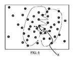
図6は、峡部を横切ってアブレーションをする領域の表示を伴う、心室頻脈回路を示す概略図である。
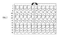
図7は、相関操作を経る2つの心電図の概略図である。
図8は、本発明による方法を実施するためのシステムの非常に簡素化した概略図である。Other advantages and features of the present invention will become apparent by reviewing the detailed description and accompanying drawings of embodiments that are by no means limited.
FIG. 1 is a three-dimensional representation of the heart chamber showing an electrical circuit in the case of ventricular tachycardia.
FIG. 2 is a simplified schematic of a reentry electrical circuit that exposes a gorge to be identified.
3-5 are schematic views of a set of stimulation points in the heart chamber. These different drawings show different stages of pair correlation between different stimulus points and constitute a density map that allows groups to be formed between highly correlated stimulus points.
FIG. 6 is a schematic showing a ventricular tachycardia circuit with an indication of the area ablating across the isthmus.
FIG. 7 is a schematic view of two electrocardiograms that undergo a correlation operation.
FIG. 8 is a very simplified schematic of a system for carrying out the method according to the invention.
先行技術では、基準ECGを有するように心室頻脈エピソードを誘発することが時に必要であった。次いで、これを他の洞リズムECG(正常心機能)と比較した。本発明では、時に人工的に誘発されるこのエピソードが回避される。実際、これは恒久的なペースメーカまたは除細動器を装備した患者にとっては複雑化する可能性がある。
本発明は、図1に見られるように、心臓の3次元表現を有することを可能にする3Dマッピングのシステムに関与する。特に、左心室1が、全体として区別されている。これは、先立つ梗塞の後遺症を呈している患者の、左心室の振幅のマッピングである。健全な領域は、マッピングに描かれた回路2の外に完全に現れ、梗塞の後遺症は完全にこの回路2内に現れている。Prior art sometimes required to induce a ventricular tachycardia episode to have a reference ECG. This was then compared to other sinus rhythm ECGs (normal cardiac function). In the present invention, this episode, which is sometimes artificially induced, is avoided. In fact, this can be complicated for patients with permanent pacemakers or defibrillators.
The present invention relates to a system of 3D mapping that allows a three-dimensional representation of the heart, as seen in FIG. In particular, the left ventricle 1 is distinguished as a whole. This is a mapping of left ventricular amplitude in patients presenting with the sequelae of a prior infarct. The healthy area appears completely outside the circuit 2 depicted in the mapping, and the sequelae of the infarct appear completely inside this circuit 2.
回路2は、図2にさらに明確に示されている。この回路は、頻脈のエピソード時の脱分極前部の経路を示す。すべての心室頻脈は、8の数字を形成する二様のループの形をなすリエントリ回路2により表すことができ、2つのループ3および4は、峡部を画定する障壁5および6の周りに逆方向で循環している脱分極前部のシートである。峡部は、マッピングされた不整脈の、不整脈背景因子を形成する中央の領域7である。
心室頻脈の治療は、峡部のアブレーションを行うことに相当する。より正確には、峡部の一部を高周波の波によって焼灼し、そこに裂け目を生じさせて、そのため脱分極波の伝播を妨げるようにする。
本発明は、特に、アブレーション領域を先行の心室頻脈ECGに頼らずに判定するという事実に関して優れている。
これを行うために、心腔のいくつかの点を刺激するために約10秒間カテーテルが使用される。各刺激点で、12誘導ECGが得られる。図2は、これらの点のランダムな分布を示している。図2〜図6に示されている回路2は先験的に知られていない。単に理解を促すために表されている。点の分布はランダムなこともあるが、例えば、表面またはボリュームを均一に覆うような、規則的な、特に既定の様式で得ることもある。したがって、分布は、均質であり得るか、生理学的基準の関数として定義できる。
第2のステップでは、地理的に近いいくつかの点をまとめて群化する。このように構成されたこれらの群は、重なり合っていてもよく、そのため1つの点は複数の群に属することができる。各群は、互いに地理的に近くにある点の系統群である。図3では、例えば4つの系統群13、14、15および16が見られる。
系統群の各対について相関係数を判定する。この目的のために、各刺激点に関連する12のリードを考慮に入れながら、Bard法を用いる。したがって、系統群16に関して図4で非常に図式的に見られるように、異なる刺激点間の繋がりに関する、密度のマッピングが確立される。各系統群において、段階的に相関係数を判定することを可能にする技法を利用することができ、系統群のすべての対について必ずこの係数を計算するわけではない。
図7は、洞リズムにおける2つの点の刺激後に得られる、2つの心電図の2セットの信号が見られることを示す。先行技術とは異なり、先立つ心室頻脈に由来する基準ECGは今回使用しない。ECGは互いに、好ましくは系統群で、または一般的な方法で比較される。
次いで、実質的に同じ密度を有する点、すなわち上記で構成された系統群と独立して、強く共に繋がっている点が特定される。このようにして、群17と18について、図5に示すように、点の群が共に強く繋がっている。
図5には、流域線8が特定されている。すなわち、急な傾斜が注目される場所であり、2つの群17と18との間の本質的な相違である。これは、2つの隣接する群を分離する「断崖」として表すことができる。これは、流域線についての技法、または間の繋がりが最も弱い2つの隣接する群を検出することを可能にする任意の他の技法によって行われる。この断崖は低伝導領域に相応している。
理想的には、流域線8は焼いて消失させる領域である。図6において、峡部は、流域線8に対して実質的に垂直な領域である。峡部を分断するのを可能にするアブレーションは、流域線とは異なる任意の他の場所で行ってもよい。
正確に流域線を計算するのに刺激点が十分でない場合、示された領域(複数可)の周りの他の刺激点を取得して、確実に流域線を計算する。Circuit 2 is shown more clearly in FIG. This circuit shows the pre-depolarization pathway during episodes of tachycardia. All ventricular tachycardia can be represented by a reentry circuit 2 in the form of two loops forming the number eight, with two
Treatment of ventricular tachycardia is equivalent to ablation of the isthmus. More precisely, part of the isthmus is cauterized by high frequency waves, creating crevices in it, thus preventing the propagation of depolarized waves.
The present invention is particularly excellent in the fact that the ablation region is determined without relying on the preceding ventricular tachycardia ECG.
To do this, a catheter is used for about 10 seconds to stimulate some points in the heart chamber. At each stimulation point, a 12-lead ECG is obtained. FIG. 2 shows the random distribution of these points. The circuit 2 shown in FIGS. 2 to 6 is a priori unknown. It is expressed merely to promote understanding. The distribution of points can be random, but can also be obtained in a regular, especially pre-determined fashion, for example, to evenly cover a surface or volume. Therefore, the distribution can be homogeneous or can be defined as a function of physiological criteria.
In the second step, some geographically close points are grouped together. These groups constructed in this way may overlap, so that one point can belong to a plurality of groups. Each group is a phylogenetic group of points that are geographically close to each other. In FIG. 3, for example, four
Determine the correlation coefficient for each pair of strains. For this purpose, the Bard method is used, taking into account the 12 leads associated with each stimulus point. Therefore, a density mapping for the connections between different stimulus points is established, as can be seen very schematicly in FIG. 4 for the
FIG. 7 shows that two sets of signals of two electrocardiograms obtained after stimulation of two points in sinus rhythm are seen. Unlike the prior art, the reference ECG derived from the preceding ventricular tachycardia is not used this time. ECGs are compared to each other, preferably in strains or in common ways.
Then, points having substantially the same density, that is, points that are strongly connected together independently of the system group constructed above are identified. In this way, for
In FIG. 5, the
Ideally, the
If there are not enough stimulus points to calculate the basin line accurately, obtain other stimulus points around the indicated area (s) to ensure that the basin line is calculated.
図8は、本発明の実施を可能にするシステムを概略的に示す。少なくとも1つのマイクロプロセッサ、メモリスペース、外部周辺機器への通信カード、入出力コンポーネント、および表示手段を備えた処理ユニット9が見られる。この処理ユニットは、マッピング装置10に接続され、この装置は一方の端部が患者の心腔の異なる部位に配置され得るカテーテル11を備える。また、マッピング装置10は、3Dマッピングを生成し、したがって12誘導ECGを生成するための電極(図示せず)に接続される。
カテーテルは、心腔の任意の点を刺激することを可能にする。また、高周波アブレーションを実行することもできる。FIG. 8 schematically shows a system that enables the implementation of the present invention. A
Catheter allows stimulation of any point in the heart chamber. It is also possible to perform high frequency ablation.
3Dマッピングを生成するために、電磁放射線源が使用される。これは、患者が位置する診察台の下に位置する三角形のフレームの頂点に配置される。電磁センサの1つ(空間的な基準)が、皮膚用パッチに組み込まれる。これは、蛍光透視の下、患者の背中のレベルで、心陰影と反対側に位置する。他のセンサは、検査中にマッピングされる心腔の心内膜の表面のレベルで、異なる点に移動されるアブレーションカテーテルの遠位端のレベルに組み込まれる。このカテーテルの動きは、モニタ上で、リアルタイムで観察することができる。所与の心腔におけるカテーテルの新たな各位置において、その位置は、モニタ上に現れる点の形態で取得することができる。このようにして得られた点は、異なる点の間に仮想上の面を作成するコンピュータプログラムによって自動的に共に繋げられ、その累算により、マップされる心腔の心内膜の輪郭に正確に沿った3次元の幾何学的形状が得られる。カテーテルには電極が設けられ、これは心腔の仮想での再構成を形成する各点のレベルで、双極性および単極性の内腔内信号を得ることを可能にする。したがって、得られた信号の双極または単極性の振幅に相関するカラーコーディングを使用して、検査した心腔の振幅のマッピングを得ることが可能である。
図8には、12誘導ECGの製造を可能にする電気生理学的ラック12も示されている。An electromagnetic radiation source is used to generate the 3D mapping. It is placed at the apex of a triangular frame located below the examination table where the patient is located. One of the electromagnetic sensors (spatial reference) is incorporated into the skin patch. It is located at the level of the patient's back under fluoroscopy, opposite the cardiac shadow. Other sensors are integrated at the level of the distal end of the ablation catheter that is moved to a different point at the level of the endocardial surface of the heart chamber that is mapped during the examination. The movement of this catheter can be observed in real time on the monitor. At each new position of the catheter in a given heart chamber, that position can be obtained in the form of points appearing on the monitor. The points thus obtained are automatically connected together by a computer program that creates a virtual surface between the different points, and the accumulation accurately matches the contour of the endocardium of the mapped heart chamber. A three-dimensional geometric shape along the line is obtained. The catheter is provided with electrodes, which allow for bipolar and unipolar intraluminal signals at the level of each point forming a virtual reconstruction of the heart chamber. Therefore, it is possible to obtain a mapping of the examined heart chamber amplitudes using color coding that correlates with the bipolar or unipolar amplitudes of the resulting signal.
FIG. 8 also shows an
当然、本発明は、上述してきた例に限定されず、本発明の範囲を越えることなく、これらの例に対して多くの調整を加えることができる。本発明は、任意選択的に磁気共鳴画像法を加えることができる心腔の3Dマッピングと、1セットの刺激点である洞リズムのECGとを入力で受信する処理ユニットからなることができる。処理ユニットの出力は、流域線が重畳して表示されている心腔の画像とすることができる。この流域線は、空間座標のセットの形で表すことができ、アブレーションに使用することができる。
本発明による方法は、心室頻脈の間の12誘導ECGの利用可能性とは無関係に、梗塞後心室頻脈の峡部の特定を、好都合にも可能にする。今後は、多数の梗塞後の患者用のカテーテルを用いた高周波アブレーションによる予防処置を行うことが可能である。Of course, the present invention is not limited to the examples described above, and many adjustments can be made to these examples without going beyond the scope of the present invention. The present invention can consist of a processing unit that receives input from a 3D mapping of the heart chamber to which magnetic resonance imaging can be optionally applied and a set of stimulus points, the ECG of sinus rhythm. The output of the processing unit can be an image of the heart chamber with the basin lines superimposed. This basin line can be represented in the form of a set of spatial coordinates and can be used for ablation.
The method according to the invention conveniently allows the identification of the isthmus of post-infarct ventricular tachycardia, regardless of the availability of 12-lead ECG during ventricular tachycardia. In the future, it will be possible to perform preventive measures by high-frequency ablation using catheters for a large number of post-infarction patients.
Claims (10)
Translated fromJapanesea)2つの刺激点の表面心電図ECGを比較することによって、それぞれの2つの刺激点について相関係数を判定するステップと;
b)前記相関係数と前記3Dマッピングにおける前記刺激点の3D座標とに基づいて流域線を特定するステップと;
c)前記流域線を実質的に横切る3Dコリドーに基づいて前記峡部を判定するステップである前記方法。The processing unit configured to perform the following steps, were obtained for cardiac chamber different stimulation points, excluding ventricular tachycardia, a number from a tableface-centered electromyography ECG,three-dimensional mapping of the heart chamber a method of identifying theisthmus by the process compares the tableface-centered electromyogram ECG of a) two stimulation points, determining a correlation coefficient for each of the two stimulation points;
b) With the step of identifying the basin line based on the correlation coefficient and the 3D coordinates of the stimulus point in the 3D mapping;
c) The method of determining the isthmus based on a 3D corridor that substantially crosses the basin line.
−心腔の異なる刺激点について得られた、心室頻脈を除く、いくつかの表面心電図ECGを生成するための心電計と、
−以下のステップ:
a)2つの刺激点の表面心電図ECGを比較することによって、それぞれの2つの刺激点について相関係数を判定するステップと;
b)前記相関係数と前記3Dマッピングにおける前記刺激点の3D座標とに基づいて流域線を特定するステップと;
c)前記流域線を実質的に横切る3Dコリドーに基づいて前記峡部を判定するステップと;
を実行するよう構成される処理ユニットと
を含むシステム。A system for identifying isthmus in three-dimensional mapping of heart chambers.
- obtained for heart chambers different stimulation point, the electrocardiograph for removing ventricular tachycardia, generates a number of tableface-centered electromyogram ECG,
-The following steps:
By comparing the tableface-centered electromyogram ECG of a) two stimulation points, determining a correlation coefficient for each of the two stimulation points;
b) With the step of identifying the basin line based on the correlation coefficient and the 3D coordinates of the stimulus point in the 3D mapping;
c) With the step of determining the isthmus based on a 3D corridor that substantially crosses the basin line;
A system that contains a processing unit that is configured to run.
Applications Claiming Priority (3)
| Application Number | Priority Date | Filing Date | Title |
|---|---|---|---|
| FR1552901AFR3034548A1 (en) | 2015-04-03 | 2015-04-03 | METHOD AND SYSTEM FOR IDENTIFYING ISTHMA IN THREE DIMENSIONAL CARTOGRAPHY |
| FR1552901 | 2015-04-03 | ||
| PCT/EP2016/057237WO2016156578A1 (en) | 2015-04-03 | 2016-04-01 | Method and system for identifying an isthmus in a three-dimensional map |
Publications (3)
| Publication Number | Publication Date |
|---|---|
| JP2018510048A JP2018510048A (en) | 2018-04-12 |
| JP2018510048A5 JP2018510048A5 (en) | 2021-05-06 |
| JP6914910B2true JP6914910B2 (en) | 2021-08-04 |
Family
ID=53674086
Family Applications (1)
| Application Number | Title | Priority Date | Filing Date |
|---|---|---|---|
| JP2018502332AActiveJP6914910B2 (en) | 2015-04-03 | 2016-04-01 | Methods and systems for identifying gorges in 3D maps |
Country Status (7)
| Country | Link |
|---|---|
| US (1) | US10891728B2 (en) |
| EP (1) | EP3278269B1 (en) |
| JP (1) | JP6914910B2 (en) |
| CN (1) | CN107666858B (en) |
| CA (1) | CA2981402C (en) |
| FR (1) | FR3034548A1 (en) |
| WO (1) | WO2016156578A1 (en) |
Cited By (1)
| Publication number | Priority date | Publication date | Assignee | Title |
|---|---|---|---|---|
| WO2023022519A1 (en)* | 2021-08-17 | 2023-02-23 | 주식회사 메디컬에이아이 | System for generating plurality of pieces of standard electrocardiogram data using 2-lead electrocardiogram data |
Families Citing this family (3)
| Publication number | Priority date | Publication date | Assignee | Title |
|---|---|---|---|---|
| US11998343B2 (en) | 2021-04-19 | 2024-06-04 | Biosense Webster (Israel) Ltd. | Annotation of slow electrophysiological (EP) cardiac paths related to ventricular tachycardia (VT) |
| US20220338784A1 (en) | 2021-04-23 | 2022-10-27 | Johnson & Johnson Medical SAS | Visualization of ventricular tachycardia causing reentrant circuits via pseudo-activation maps |
| CN115192181B (en)* | 2022-06-09 | 2024-06-11 | 绍兴梅奥心磁医疗科技有限公司 | Sheath tube and catheter state control mechanical arm and linkage control system thereof |
Family Cites Families (11)
| Publication number | Priority date | Publication date | Assignee | Title |
|---|---|---|---|---|
| US6847839B2 (en)* | 2001-07-30 | 2005-01-25 | The Trustees Of Columbia University In The City Of New York | System and method for determining reentrant ventricular tachycardia isthmus location and shape for catheter ablation |
| US8583220B2 (en)* | 2005-08-02 | 2013-11-12 | Biosense Webster, Inc. | Standardization of catheter-based treatment for atrial fibrillation |
| US7918793B2 (en)* | 2005-10-28 | 2011-04-05 | Biosense Webster, Inc. | Synchronization of ultrasound imaging data with electrical mapping |
| US7907994B2 (en)* | 2007-01-11 | 2011-03-15 | Biosense Webster, Inc. | Automated pace-mapping for identification of cardiac arrhythmic conductive pathways and foci |
| US8340766B2 (en)* | 2010-10-07 | 2012-12-25 | St. Jude Medical, Atrial Fibrillation Division, Inc. | Method and system for identifying cardiac arrhythmia driver sites |
| WO2012139116A2 (en)* | 2011-04-07 | 2012-10-11 | The Johns Hopkins University | Non-invasive methods and systems for producing cardiac electrogram characteristic maps for use with catheter ablation of ventricular tachycardia |
| US10149626B1 (en)* | 2011-08-27 | 2018-12-11 | American Medical Technologies, Llc | Methods and systems for mapping and ablation of cardiac arrhythmias comprising atrial flutter |
| WO2014055980A1 (en)* | 2012-10-05 | 2014-04-10 | The Regents Of The University Of Michigan | Automated analysis of multi-lead electrocardiogram data to identify the exit sites of physiological conditions |
| EP2948053B1 (en)* | 2013-01-24 | 2018-03-28 | Dalhousie University | Computer-aided localization of site of origin of cardiac activation with discriminator leads |
| WO2014182842A1 (en)* | 2013-05-07 | 2014-11-13 | Boston Scientific Scimed Inc. | System for identifying rotor propagation vectors |
| WO2014183206A1 (en)* | 2013-05-17 | 2014-11-20 | University Health Network | System and method for decrement evoked potential (deep) mapping to identify critical components of the arrythmogenic circuit in cardiac arrhythmias |
- 2015
- 2015-04-03FRFR1552901Apatent/FR3034548A1/enactivePending
- 2016
- 2016-04-01EPEP16717851.6Apatent/EP3278269B1/enactiveActive
- 2016-04-01USUS15/564,033patent/US10891728B2/enactiveActive
- 2016-04-01CNCN201680028545.0Apatent/CN107666858B/enactiveActive
- 2016-04-01JPJP2018502332Apatent/JP6914910B2/enactiveActive
- 2016-04-01CACA2981402Apatent/CA2981402C/enactiveActive
- 2016-04-01WOPCT/EP2016/057237patent/WO2016156578A1/ennot_activeCeased
Cited By (1)
| Publication number | Priority date | Publication date | Assignee | Title |
|---|---|---|---|---|
| WO2023022519A1 (en)* | 2021-08-17 | 2023-02-23 | 주식회사 메디컬에이아이 | System for generating plurality of pieces of standard electrocardiogram data using 2-lead electrocardiogram data |
Also Published As
| Publication number | Publication date |
|---|---|
| WO2016156578A1 (en) | 2016-10-06 |
| EP3278269A1 (en) | 2018-02-07 |
| CA2981402C (en) | 2024-05-14 |
| CN107666858A (en) | 2018-02-06 |
| CA2981402A1 (en) | 2016-10-06 |
| FR3034548A1 (en) | 2016-10-07 |
| EP3278269B1 (en) | 2024-05-29 |
| JP2018510048A (en) | 2018-04-12 |
| US10891728B2 (en) | 2021-01-12 |
| US20180089825A1 (en) | 2018-03-29 |
| CN107666858B (en) | 2020-07-17 |
Similar Documents
| Publication | Publication Date | Title |
|---|---|---|
| US6370412B1 (en) | Method and apparatus for guiding ablative therapy of abnormal biological electrical excitation | |
| RU2529383C2 (en) | Device and method for automatic identification of locations of sources of biological rhythm disturbances | |
| US6760620B2 (en) | Non-invasive localization and treatment of focal atrial fibrillation | |
| US20160331262A1 (en) | Combined Electrophysiological Mapping and Cardiac Ablation Methods, Systems, Components and Devices | |
| US20150150472A1 (en) | Cardiac mapping with catheter shape information | |
| US9974462B2 (en) | Signal characterization for detecting and/or analyzing driver activity | |
| EP2948053B1 (en) | Computer-aided localization of site of origin of cardiac activation with discriminator leads | |
| Wang et al. | Noninvasive epicardial and endocardial electrocardiographic imaging of scar-related ventricular tachycardia | |
| EP3102102A1 (en) | Integrated analysis of electrophysiological data | |
| US20230181087A1 (en) | Intracardiac unipolar far field cancelation using multiple electrode cathethers | |
| JP6914910B2 (en) | Methods and systems for identifying gorges in 3D maps | |
| US8265752B2 (en) | System and method for assessing atrial electrical stability | |
| Dössel et al. | A framework for personalization of computational models of the human atria | |
| US12383184B2 (en) | Late activation of cardiac signals | |
| EP4447805A1 (en) | Intracardiac unipolar far field cancelation using multiple electrode catheters | |
| Valinoti et al. | Phase analysis of endoatrial electrograms for 3D rotor detection in atrial fibrillation | |
| Ng et al. | Fundamentals of cardiac mapping | |
| EP4098198B1 (en) | Methods, systems, devices, and components for extracting atrial signals from qrs and qrst complexes | |
| Dallet et al. | Combined signal averaging and electrocardiographic imaging method to non-invasively identify atrial and ventricular tachycardia mechanisms | |
| US20230050834A1 (en) | Methods, Systems, Devices, and Components for Extracting Atrial Signals from QRS and QRST Complexes | |
| Paccione et al. | Unipolar R: S Development in Chronic Atrial Fibrillation | |
| Lv et al. | Use of the inverse solution guidance algorithm method for RF ablation catheter guidance | |
| Armoundas | A novel technique for guiding ablative therapy of cardiac arrhythmias | |
| Zhu et al. | Simulation of intracardial potentials with anisotropic computer heart models | |
| Van Oosterom et al. | Modeling atrial fibrillation: from myocardial cells to ECG |
Legal Events
| Date | Code | Title | Description |
|---|---|---|---|
| A621 | Written request for application examination | Free format text:JAPANESE INTERMEDIATE CODE: A621 Effective date:20190318 | |
| A977 | Report on retrieval | Free format text:JAPANESE INTERMEDIATE CODE: A971007 Effective date:20200213 | |
| A131 | Notification of reasons for refusal | Free format text:JAPANESE INTERMEDIATE CODE: A131 Effective date:20200225 | |
| A601 | Written request for extension of time | Free format text:JAPANESE INTERMEDIATE CODE: A601 Effective date:20200521 | |
| A521 | Request for written amendment filed | Free format text:JAPANESE INTERMEDIATE CODE: A523 Effective date:20200825 | |
| A131 | Notification of reasons for refusal | Free format text:JAPANESE INTERMEDIATE CODE: A131 Effective date:20200929 | |
| A601 | Written request for extension of time | Free format text:JAPANESE INTERMEDIATE CODE: A601 Effective date:20201228 | |
| A524 | Written submission of copy of amendment under article 19 pct | Free format text:JAPANESE INTERMEDIATE CODE: A524 Effective date:20210326 | |
| TRDD | Decision of grant or rejection written | ||
| A01 | Written decision to grant a patent or to grant a registration (utility model) | Free format text:JAPANESE INTERMEDIATE CODE: A01 Effective date:20210629 | |
| A61 | First payment of annual fees (during grant procedure) | Free format text:JAPANESE INTERMEDIATE CODE: A61 Effective date:20210714 | |
| R150 | Certificate of patent or registration of utility model | Ref document number:6914910 Country of ref document:JP Free format text:JAPANESE INTERMEDIATE CODE: R150 | |
| R250 | Receipt of annual fees | Free format text:JAPANESE INTERMEDIATE CODE: R250 | |
| R250 | Receipt of annual fees | Free format text:JAPANESE INTERMEDIATE CODE: R250 |