JP6912604B2 - Coordinate system integration method and device with columnar body - Google Patents
Coordinate system integration method and device with columnar bodyDownload PDFInfo
- Publication number
- JP6912604B2 JP6912604B2JP2019569124AJP2019569124AJP6912604B2JP 6912604 B2JP6912604 B2JP 6912604B2JP 2019569124 AJP2019569124 AJP 2019569124AJP 2019569124 AJP2019569124 AJP 2019569124AJP 6912604 B2JP6912604 B2JP 6912604B2
- Authority
- JP
- Japan
- Prior art keywords
- coordinate system
- sensor
- calibration
- marker
- object detection
- Prior art date
- Legal status (The legal status is an assumption and is not a legal conclusion. Google has not performed a legal analysis and makes no representation as to the accuracy of the status listed.)
- Active
Links
Images


Classifications
- G—PHYSICS
- G01—MEASURING; TESTING
- G01B—MEASURING LENGTH, THICKNESS OR SIMILAR LINEAR DIMENSIONS; MEASURING ANGLES; MEASURING AREAS; MEASURING IRREGULARITIES OF SURFACES OR CONTOURS
- G01B11/00—Measuring arrangements characterised by the use of optical techniques
- G—PHYSICS
- G01—MEASURING; TESTING
- G01B—MEASURING LENGTH, THICKNESS OR SIMILAR LINEAR DIMENSIONS; MEASURING ANGLES; MEASURING AREAS; MEASURING IRREGULARITIES OF SURFACES OR CONTOURS
- G01B11/00—Measuring arrangements characterised by the use of optical techniques
- G01B11/26—Measuring arrangements characterised by the use of optical techniques for measuring angles or tapers; for testing the alignment of axes
- G—PHYSICS
- G01—MEASURING; TESTING
- G01C—MEASURING DISTANCES, LEVELS OR BEARINGS; SURVEYING; NAVIGATION; GYROSCOPIC INSTRUMENTS; PHOTOGRAMMETRY OR VIDEOGRAMMETRY
- G01C15/00—Surveying instruments or accessories not provided for in groups G01C1/00 - G01C13/00
- G—PHYSICS
- G01—MEASURING; TESTING
- G01C—MEASURING DISTANCES, LEVELS OR BEARINGS; SURVEYING; NAVIGATION; GYROSCOPIC INSTRUMENTS; PHOTOGRAMMETRY OR VIDEOGRAMMETRY
- G01C15/00—Surveying instruments or accessories not provided for in groups G01C1/00 - G01C13/00
- G01C15/02—Means for marking measuring points
- G01C15/06—Surveyors' staffs; Movable markers
Landscapes
- Physics & Mathematics (AREA)
- General Physics & Mathematics (AREA)
- Engineering & Computer Science (AREA)
- Radar, Positioning & Navigation (AREA)
- Remote Sensing (AREA)
- Length Measuring Devices By Optical Means (AREA)
- Length Measuring Devices With Unspecified Measuring Means (AREA)
Description
Translated fromJapanese本開示は、座標系統合方法、及び柱状体を備える装置に関する。 The present disclosure relates to a coordinate system integration method and an apparatus including a columnar body.
例えば、建設機械等に物体検出センサを取り付けて、物体検出センサを用いて建設機械等の周囲の物体を検出することが行われている。物体検出センサを用いて物体を検出する場合、建設機械等に予め設定された基準座標系と物体検出センサの設置位置及び姿勢とを対応付けること、すなわち、基準座標系と物体検出センサのセンサ座標系とを対応付けることが行われている。 For example, an object detection sensor is attached to a construction machine or the like, and an object around the construction machine or the like is detected by using the object detection sensor. When detecting an object using an object detection sensor, the reference coordinate system preset in the construction machine or the like is associated with the installation position and orientation of the object detection sensor, that is, the reference coordinate system and the sensor coordinate system of the object detection sensor. Is associated with.
例えば、特許文献1には、道路を走行する車両を監視する監視カメラにおいて、道路平面と監視カメラの設置位置及び姿勢とを対応付けることが記載されている。 For example, Patent Document 1 describes that in a surveillance camera that monitors a vehicle traveling on a road, the road plane is associated with the installation position and posture of the surveillance camera.
特許文献1に記載された方法では、監視カメラによって特徴点を検出し、特徴点の検出結果に基づいて道路平面と監視カメラの設置位置及び姿勢とを対応付けている。これと同様に、建設機械等に取り付けられた物体検出センサの検出結果に基づいて基準座標系と物体検出センサの設置位置及び姿勢とを対応付けることが考えられる。しかしながら、設置位置及び姿勢の対応付けを行う対象となる物体検出センサの検出結果を用いる場合、基準座標系とセンサ座標系との対応付けの精度が物体検出センサの検出精度に依存する。 In the method described in Patent Document 1, feature points are detected by a surveillance camera, and the road plane is associated with the installation position and posture of the surveillance camera based on the detection result of the feature points. Similarly, it is conceivable to associate the reference coordinate system with the installation position and orientation of the object detection sensor based on the detection result of the object detection sensor attached to the construction machine or the like. However, when the detection result of the object detection sensor to be associated with the installation position and the orientation is used, the accuracy of the association between the reference coordinate system and the sensor coordinate system depends on the detection accuracy of the object detection sensor.
そこで、本開示は、物体検出センサの検出精度に依存することなく、対象装置の基準座標系と物体検出センサのセンサ座標系とを対応付けることが可能な座標系統合方法、及び柱状体を備える装置を説明する。 Therefore, the present disclosure includes a coordinate system integration method capable of associating a reference coordinate system of a target device with a sensor coordinate system of an object detection sensor without depending on the detection accuracy of the object detection sensor, and a device including a columnar body. Will be explained.
本開示の一態様は、対象装置に取り付けられ対象装置の周囲の物体を検出する物体検出センサのセンサ座標系と、対象装置に対して予め設定された基準座標系とを対応付ける座標系統合方法であって、物体検出センサを対象装置に取り付ける取付冶具に設置されるとともにセンサ座標系を定義する3以上の校正用マーカと、対象装置に設置されるとともに基準座標系を定義する3以上の基準マーカと、を計測装置によって計測する計測工程と、計測工程の計測結果に基づいて、校正用マーカによって定義されるセンサ座標系と基準マーカによって定義される基準座標系とを対応付ける統合工程と、を含む。 One aspect of the present disclosure is a coordinate system integration method that associates a sensor coordinate system of an object detection sensor attached to a target device with an object around the target device with a reference coordinate system preset for the target device. There are three or more calibration markers that are installed on the mounting tool that attaches the object detection sensor to the target device and define the sensor coordinate system, and three or more reference markers that are installed on the target device and define the reference coordinate system. Includes a measurement process that measures and, and an integration process that associates the sensor coordinate system defined by the calibration marker with the reference coordinate system defined by the reference marker based on the measurement results of the measurement process. ..
本開示によれば、物体検出センサの検出精度に依存することなく、対象装置の基準座標系と物体検出センサのセンサ座標系とを対応付けることができる。 According to the present disclosure, it is possible to associate the reference coordinate system of the target device with the sensor coordinate system of the object detection sensor without depending on the detection accuracy of the object detection sensor.
本開示の一態様は、対象装置に取り付けられ対象装置の周囲の物体を検出する物体検出センサのセンサ座標系と、対象装置に対して予め設定された基準座標系とを対応付ける座標系統合方法であって、物体検出センサを対象装置に取り付ける取付冶具に設置されるとともにセンサ座標系を定義する3以上の校正用マーカと、対象装置に設置されるとともに基準座標系を定義する3以上の基準マーカと、を計測装置によって計測する計測工程と、計測工程の計測結果に基づいて、校正用マーカによって定義されるセンサ座標系と基準マーカによって定義される基準座標系とを対応付ける統合工程と、を含む。 One aspect of the present disclosure is a coordinate system integration method that associates a sensor coordinate system of an object detection sensor attached to a target device with an object around the target device with a reference coordinate system preset for the target device. There are three or more calibration markers that are installed on the mounting tool that attaches the object detection sensor to the target device and define the sensor coordinate system, and three or more reference markers that are installed on the target device and define the reference coordinate system. Includes a measurement process that measures and, and an integration process that associates the sensor coordinate system defined by the calibration marker with the reference coordinate system defined by the reference marker based on the measurement results of the measurement process. ..
この座標系統合方法では、計測工程において、校正用マーカと基準マーカとが計測装置によって計測される。そして、統合工程において、計測工程の計測結果に基づいて、センサ座標系と基準座標系とが対応付けられる。すなわち、計測装置の計測結果に基づいてセンサ座標系及び基準座標系が特定されてセンサ座標系と基準座標系とが対応付けられており、物体検出センサの検出結果は用いられていない。従って、この座標系統合方法では、物体検出センサの検出精度に依存することなく、対象装置の基準座標系と物体検出センサのセンサ座標系とを対応付けることができる。 In this coordinate system integration method, the calibration marker and the reference marker are measured by the measuring device in the measuring process. Then, in the integration process, the sensor coordinate system and the reference coordinate system are associated with each other based on the measurement result of the measurement process. That is, the sensor coordinate system and the reference coordinate system are specified based on the measurement result of the measuring device, and the sensor coordinate system and the reference coordinate system are associated with each other, and the detection result of the object detection sensor is not used. Therefore, in this coordinate system integration method, the reference coordinate system of the target device and the sensor coordinate system of the object detection sensor can be associated with each other without depending on the detection accuracy of the object detection sensor.
物体検出センサは、第1物体検出センサと、第2物体検出センサと、を含み、取付冶具は、第1物体検出センサを対象装置に取り付ける第1取付冶具と、第2物体検出センサを対象装置に取り付ける第2取付冶具と、を含み、校正用マーカは、第1取付冶具に設置されるとともに第1物体検出センサの第1センサ座標系を定義する3以上の第1校正用マーカと、第2取付冶具に設置されるとともに第2物体検出センサの第2センサ座標系を定義する3以上の第2校正用マーカと、を含み、基準マーカは、対象装置に3以上設置され、計測装置が3以上の第1校正用マーカを計測するときに少なくとも3以上の基準マーカが第1校正用マーカとともに計測される方向を向き、計測装置が3以上の第2校正用マーカを計測するときに少なくとも3以上の基準マーカが第2校正用マーカとともに計測される方向を向き、計測工程では、3以上の第1校正用マーカと3以上の基準マーカとを計測装置によって計測し、3以上の第2校正用マーカと3以上の基準マーカとを計測装置によって計測し、統合工程では、第1校正用マーカによって定義される第1センサ座標系と基準座標系とを対応付け、第2校正用マーカによって定義される第2センサ座標系と基準座標系とを対応付けてもよい。この場合、第1物体検出センサと第2物体検出センサとが異なる位置に設けられていても、計測工程において第1校正用マーカと基準マーカとを計測でき、第2校正用マーカと基準マーカとを計測できる。また、物体検出センサが複数設けられていても、それぞれの物体検出センサのセンサ座標系を基準座標系に対応付けることができる。 The object detection sensor includes a first object detection sensor and a second object detection sensor, and the mounting jig includes a first mounting jig that attaches the first object detection sensor to the target device and a second object detection sensor as the target device. The calibration markers, including the second mounting tool attached to the first mounting tool, include three or more first calibration markers that are mounted on the first mounting tool and define the first sensor coordinate system of the first object detection sensor. 2 The reference markers are installed in the target device, and the measuring device includes 3 or more 2nd calibration markers that are installed in the mounting jig and define the 2nd sensor coordinate system of the 2nd object detection sensor. When measuring 3 or more first calibration markers, at least 3 or more reference markers face the measurement direction together with the first calibration marker, and when the measuring device measures 3 or more second calibration markers, at least Three or more reference markers face the measurement direction together with the second calibration marker, and in the measurement process, three or more first calibration markers and three or more reference markers are measured by a measuring device, and three or more second calibration markers are measured. The calibration marker and three or more reference markers are measured by the measuring device, and in the integration process, the first sensor coordinate system defined by the first calibration marker and the reference coordinate system are associated with each other, and the second calibration marker is used. The defined second sensor coordinate system and the reference coordinate system may be associated with each other. In this case, even if the first object detection sensor and the second object detection sensor are provided at different positions, the first calibration marker and the reference marker can be measured in the measurement process, and the second calibration marker and the reference marker can be measured. Can be measured. Further, even if a plurality of object detection sensors are provided, the sensor coordinate system of each object detection sensor can be associated with the reference coordinate system.
本開示の他の一態様は、対象装置に取り付けられ対象装置の周囲の物体を検出する物体検出センサのセンサ座標系と、対象装置に対して予め設定された基準座標系とを対応付ける座標系統合方法であって、物体検出センサを対象装置に取り付ける取付冶具又は物体検出センサに設けられるとともにセンサ座標系を定義するセンサ座標特定部と、取付冶具に設置されるとともに校正用マーカ座標系を定義する3以上の校正用マーカと、を第1計測装置によって計測する第1計測工程と、第1計測工程の計測結果に基づいて、センサ座標特定部によって定義されるセンサ座標系と、校正用マーカによって定義される校正用マーカ座標系と、を対応付ける第1対応付工程と、3以上の校正用マーカと、対象装置に設置されるとともに基準座標系を定義する3以上の基準マーカと、を第2計測装置によって計測する第2計測工程と、第2計測工程の計測結果に基づいて、校正用マーカによって定義される校正用マーカ座標系と、基準マーカによって定義される基準座標系とを対応付ける第2対応付工程と、第1対応付工程で対応付けられたセンサ座標系及び校正用マーカ座標系と、第2対応付工程で対応付けられた校正用マーカ座標系及び基準座標系と、に基づいて、センサ座標系と基準座標系とを対応付ける統合工程と、を含む。 Another aspect of the present disclosure is a coordinate system integration that associates the sensor coordinate system of an object detection sensor attached to the target device with an object around the target device with a reference coordinate system preset for the target device. It is a method that defines a sensor coordinate identification unit that is provided on a mounting jig or object detection sensor that attaches an object detection sensor to a target device and defines a sensor coordinate system, and a marker coordinate system that is installed on the mounting jig and defines a calibration marker coordinate system. With the sensor coordinate system defined by the sensor coordinate identification unit and the calibration marker based on the measurement results of the first measurement step of measuring three or more calibration markers by the first measuring device and the first measurement step. The first corresponding step for associating the defined calibration marker coordinate system, the three or more calibration markers, and the three or more reference markers installed in the target device and defining the reference coordinate system are second. Based on the measurement results of the second measurement process measured by the measuring device and the measurement result of the second measurement process, the second measurement marker coordinate system defined by the calibration marker and the reference coordinate system defined by the reference marker are associated with each other. Based on the corresponding step, the sensor coordinate system and the calibration marker coordinate system associated in the first correspondence step, and the calibration marker coordinate system and the reference coordinate system associated in the second correspondence step. , Including an integration step of associating a sensor coordinate system with a reference coordinate system.
この座標系統合方法では、第1計測工程においてセンサ座標特定部と校正用マーカとが第1計測装置によって計測され、第2計測工程において校正用マーカと基準マーカとが第2計測装置によって計測される。第1対応付工程においてセンサ座標系と校正用マーカ座標系とが対応付けられ、第2対応付工程において校正用マーカ座標系と基準座標系とが対応付けられる。そして、統合工程において、センサ座標系と基準座標系とが対応付けられる。すなわち、第1計測装置及び第2計測装置の計測結果に基づいて各座標系の対応付けが行われており、物体検出センサの検出結果は用いられていない。従って、この座標系統合方法では、物体検出センサの検出精度に依存することなく、対象装置の基準座標系と物体検出センサのセンサ座標系とを対応付けることができる。 In this coordinate system integration method, the sensor coordinate identification unit and the calibration marker are measured by the first measuring device in the first measurement step, and the calibration marker and the reference marker are measured by the second measuring device in the second measurement step. NS. In the first correspondence step, the sensor coordinate system and the calibration marker coordinate system are associated, and in the second correspondence step, the calibration marker coordinate system and the reference coordinate system are associated. Then, in the integration process, the sensor coordinate system and the reference coordinate system are associated with each other. That is, each coordinate system is associated with each other based on the measurement results of the first measuring device and the second measuring device, and the detection result of the object detection sensor is not used. Therefore, in this coordinate system integration method, the reference coordinate system of the target device and the sensor coordinate system of the object detection sensor can be associated with each other without depending on the detection accuracy of the object detection sensor.
物体検出センサは、第1物体検出センサと、第2物体検出センサと、を含み、取付冶具は、第1物体検出センサを対象装置に取り付ける第1取付冶具と、第2物体検出センサを対象装置に取り付ける第2取付冶具と、を含み、センサ座標特定部は、第1取付冶具又は第1物体検出センサに設けられるとともに第1物体検出センサの第1センサ座標系を定義する第1センサ座標特定部と、第2取付冶具又は第2物体検出センサに設けられるとともに第2物体検出センサの第2センサ座標系を定義する第2センサ座標特定部と、を含み、校正用マーカは、第1取付冶具に設置されるとともに第1校正用マーカ座標系を定義する3以上の第1校正用マーカと、第2取付冶具に設置されるとともに第2校正用マーカ座標系を定義する3以上の第2校正用マーカと、を含み、基準マーカは、対象装置に3以上設置され、第2計測装置が3以上の第1校正用マーカを計測するときに少なくとも3以上の基準マーカが第1校正用マーカとともに計測される方向を向き、第2計測装置が3以上の第2校正用マーカを計測するときに少なくとも3以上の基準マーカが第2校正用マーカとともに計測される方向を向き、第1計測工程では、第1センサ座標特定部と3以上の第1校正用マーカとを第1計測装置によって計測し、第2センサ座標特定部と3以上の第2校正用マーカとを第1計測装置によって計測し、第1対応付工程では、第1センサ座標特定部によって定義される第1センサ座標系と第1校正用マーカによって定義される第1校正用マーカ座標系とを対応付け、第2センサ座標特定部によって定義される第2センサ座標系と第2校正用マーカによって定義される第2校正用マーカ座標系とを対応付け、第2計測工程では、3以上の第1校正用マーカと3以上の基準マーカとを第2計測装置によって計測し、3以上の第2校正用マーカと3以上の基準マーカとを第2計測装置によって計測し、第2対応付工程では、第1校正用マーカによって定義される第1校正用マーカ座標系と基準マーカによって定義される基準座標系とを対応付け、第2校正用マーカによって定義される第2校正用マーカ座標系と基準マーカによって定義される基準座標系とを対応付け、統合工程では、第1対応付工程で対応付けられた第1センサ座標系及び第1校正用マーカ座標系と、第2対応付工程で対応付けられた第1校正用マーカ座標系及び基準座標系と、に基づいて、第1センサ座標系と基準座標系とを対応付け、第1対応付工程で対応付けられた第2センサ座標系及び第2校正用マーカ座標系と、第2対応付工程で対応付けられた第2校正用マーカ座標系及び基準座標系と、に基づいて、第2センサ座標系と基準座標系とを対応付けてもよい。この場合、第1物体検出センサと第2物体検出センサとが異なる位置に設けられていても、第2計測工程において第1校正用マーカと基準マーカとを計測でき、第2校正用マーカと基準マーカとを計測できる。また、物体検出センサが複数設けられていても、それぞれの物体検出センサのセンサ座標系を基準座標系に対応付けることができる。 The object detection sensor includes a first object detection sensor and a second object detection sensor, and the mounting tool includes a first mounting tool that attaches the first object detection sensor to the target device and a second object detection sensor as the target device. The sensor coordinate identification unit includes the second attachment jig to be attached to the first attachment jig or the first object detection sensor, and defines the first sensor coordinate system of the first object detection sensor. The calibration marker includes a unit and a second sensor coordinate identification unit provided on the second attachment jig or the second object detection sensor and defining the second sensor coordinate system of the second object detection sensor, and the calibration marker is the first attachment. Three or more first calibration markers installed on the jig and defining the first calibration marker coordinate system, and three or more second markers installed on the second mounting tool and defining the second calibration marker coordinate system. Three or more reference markers are installed in the target device, including a calibration marker, and when the second measuring device measures three or more first calibration markers, at least three or more reference markers are the first calibration markers. When the second measuring device measures three or more second calibration markers, at least three or more reference markers face the direction to be measured together with the second calibration marker, and the first measurement step Then, the first sensor coordinate identification unit and three or more first calibration markers are measured by the first measuring device, and the second sensor coordinate identification unit and three or more second calibration markers are measured by the first measuring device. Then, in the first corresponding step, the first sensor coordinate system defined by the first sensor coordinate identification unit and the first calibration marker coordinate system defined by the first calibration marker are associated with each other, and the second sensor coordinates. The second sensor coordinate system defined by the specific unit is associated with the second calibration marker coordinate system defined by the second calibration marker, and in the second measurement step, three or more first calibration markers and three or more are used. The reference marker is measured by the second measuring device, and three or more second calibration markers and three or more reference markers are measured by the second measuring device. In the second corresponding process, the first calibration marker is used. The defined first calibration marker coordinate system is associated with the reference coordinate system defined by the reference marker, and the second calibration marker coordinate system defined by the second calibration marker and the reference coordinate defined by the reference marker. In the integration process, the system is associated with the first sensor coordinate system and the first calibration marker coordinate system associated in the first corresponding step, and the first calibration marker associated in the second associated step. With the coordinate system and the reference coordinate system , The first sensor coordinate system and the reference coordinate system are associated with each other, and the second sensor coordinate system and the second calibration marker coordinate system associated with each other in the first corresponding step are associated with each other. The second sensor coordinate system and the reference coordinate system may be associated with each other based on the associated second calibration marker coordinate system and the reference coordinate system. In this case, even if the first object detection sensor and the second object detection sensor are provided at different positions, the first calibration marker and the reference marker can be measured in the second measurement step, and the second calibration marker and the reference can be measured. Can measure with markers. Further, even if a plurality of object detection sensors are provided, the sensor coordinate system of each object detection sensor can be associated with the reference coordinate system.
物体検出センサは、対象装置の周囲に複数のレーザ光を照射することによって物体を検出するセンサであってもよい。例えば、この物体検出センサによって基準マーカを検出する場合、レーザ光の照射の間隔によっては基準マーカが検出されないことが考えられる。しかしながら、この座標系統合方法では、物体検出センサの検出結果を用いずにセンサ座標系と基準座標系とを対応付けることができるため、物体検出センサの検出精度に依存することなく座標系の対応付けを行うことができる。 The object detection sensor may be a sensor that detects an object by irradiating a plurality of laser beams around the target device. For example, when the reference marker is detected by this object detection sensor, it is conceivable that the reference marker is not detected depending on the interval of laser beam irradiation. However, in this coordinate system integration method, since the sensor coordinate system and the reference coordinate system can be associated without using the detection result of the object detection sensor, the coordinate system can be associated without depending on the detection accuracy of the object detection sensor. It can be performed.
本開示の更に他の一態様に係る柱状体を備える装置は、移動可能な柱状体と、柱状体に設けられ、柱状体に対して予め設定された基準座標系を定義する3以上の基準マーカと、柱状体とともに移動する物体検出センサと、物体検出センサもしくは物体検出センサに取り付けられた取付冶具に設けられ、物体検出センサのセンサ座標系を定義する3以上の校正用マーカと、を備え、3以上の基準マーカと3以上の校正用マーカとは、1の地点から視認可能に設けられている。 The device including the columnar body according to still another aspect of the present disclosure includes a movable columnar body and three or more reference markers provided on the columnar body and defining a reference coordinate system preset for the columnar body. And an object detection sensor that moves with the columnar body, and three or more calibration markers that are provided on the object detection sensor or the mounting tool attached to the object detection sensor and define the sensor coordinate system of the object detection sensor. Three or more reference markers and three or more calibration markers are visibly provided from one point.
この柱状体を備える装置では、3以上の基準マーカと3以上の校正用マーカとが1の地点から視認できる。これにより、校正用マーカと基準マーカとを計測することで、センサ座標系と基準座標系との対応付けが可能となる。すなわち、物体検出センサの検出結果を用いることなく、センサ座標系と基準座標系とが対応付けられる。従って、この柱状体を備える装置では、物体検出センサの検出精度に依存することなく、柱状体に設定された基準座標系と物体検出センサのセンサ座標系とを対応付けることができる。 In the device provided with this columnar body, three or more reference markers and three or more calibration markers can be visually recognized from one point. As a result, the sensor coordinate system and the reference coordinate system can be associated with each other by measuring the calibration marker and the reference marker. That is, the sensor coordinate system and the reference coordinate system are associated with each other without using the detection result of the object detection sensor. Therefore, in the device including the columnar body, the reference coordinate system set in the columnar body and the sensor coordinate system of the object detection sensor can be associated with each other without depending on the detection accuracy of the object detection sensor.
以下、本開示の実施形態について図面を参照しながら説明する。なお、図面の説明において同一の要素には同一の符号を付し、重複する説明を省略する。 Hereinafter, embodiments of the present disclosure will be described with reference to the drawings. In the description of the drawings, the same elements are designated by the same reference numerals, and duplicate description will be omitted.
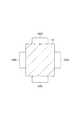
本実施形態では、図1に示される油圧ショベル(対象装置、装置)1に対して予め設定された基準座標系と、油圧ショベル1に取り付けられた物体検出センサ110A〜110D(図3(a)〜図3(d)参照)の各センサ座標系とを対応付ける座標系統合方法について説明する。ここで、2つの座標系を対応付けることとは、一方の座標系に対する他方の座標系の位置及び姿勢を把握することをいう。すなわち、2つの座標系を対応付けることとは、一方の座標系から他方の座標系への並進と回転による座標変換パラメータを得て、一方の座標系で得られた座標を他方の座標系の座標に変換できる状態にすることをいう。 In the present embodiment, the reference coordinate system preset for the hydraulic excavator (target device, device) 1 shown in FIG. 1 and the
油圧ショベル1は、自身を走行させるための走行体11と、走行体11上に設けられた旋回体10と、旋回体10の前方に取り付けられるブーム12と、ブーム12の先端に取り付けられるアーム(柱状体)13と、アーム13の先端に取り付けられるバケット14とを備えている。油圧により、ブーム12は旋回体10に対して揺動し、アーム13はブーム12に対して揺動し、バケット14はアーム13に対して揺動する。 The hydraulic excavator 1 includes a traveling
図1及び図2に示されるように、アーム13は、四角柱状に形成されている。本実施形態では、アーム13の軸を第1軸とし、第1軸に直交する軸と第2軸とし、第1軸及び第2軸に直交する軸を第3軸としたときに、第1軸、第2軸及び第3軸によって定義される座標系を、油圧ショベル1(アーム13)に対して予め設定された基準座標系とする。基準座標系の原点は、アーム13の軸方向における所定の位置とする。 As shown in FIGS. 1 and 2, the
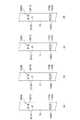
アーム13の外周面の各面には、センサユニット100A〜100Dがそれぞれ取り付けられている。図3(a)に示されるように、アーム13におけるセンサユニット100Aが取り付けられた面には、基準マーカ部200Aが設置されている。基準マーカ部200Aは、3つの基準マーカ201Aによって構成されている。基準マーカ201Aは、基準座標系を定義している。すなわち、基準マーカ201Aは、基準座標系を示すように、アーム13の外周面に設置されている。3つの基準マーカ201Aを計測することによって、基準座標系が導かれる。例えば、3つの基準マーカ201Aによって導かれる三次元座標系と基準座標系とがずれている場合、導かれた三次元座標系を基準座標系に合わせるための変換情報に基づいて、基準マーカ201Aの計測結果から基準座標系が導かれてもよい。
3つの基準マーカ201Aに基づいて三次元座標系を導く方法としては、周知の方法を用いることができる。例えば、2つの基準マーカ201Aによって1つ目の軸を定める。3つの基準マーカ201Aによって三角形の面を定義し、面の法線を2つ目の軸とする。これらの2つの軸に直交する線を3つ目の軸とする。なお、基準マーカ201Aは、一例として、十字が付された銀色のプレートであってもよい。各基準マーカ201Aには、識別情報が付されており、識別情報を用いて基準座標系が導かれてもよい。 A well-known method can be used as a method for deriving the three-dimensional coordinate system based on the three
図3(b)に示されるように、アーム13におけるセンサユニット100Bが取り付けられた面には、3つの基準マーカ201Bによって構成される基準マーカ部200Bが設置されている。図3(c)に示されるように、アーム13におけるセンサユニット100Cが取り付けられた面には、3つの基準マーカ201Cによって構成される基準マーカ部200Cが設置されている。図3(d)に示されるように、アーム13におけるセンサユニット100Dが取り付けられた面には、3つの基準マーカ201Dによって構成される基準マーカ部200Dが設置されている。3つの基準マーカ201B、3つの基準マーカ201C、及び3つの基準マーカ201Dは、3つの基準マーカ201Aと同様に、基準座標系を定義している。すなわち、3つの基準マーカ201A、3つの基準マーカ201B、3つの基準マーカ201C、及び3つの基準マーカ201Dは、同じ座標系(油圧ショベル1に対して予め設定された基準座標系)を定義している。 As shown in FIG. 3B, a
センサユニット100Aは、図4(a)及び図4(b)に示されるように、物体検出センサ(第1物体検出センサ)110Aと、取付冶具(第1取付冶具)120Aとを有している。物体検出センサ110Aは、アーム13の周囲の物体を検出するセンサである。本実施形態において、物体検出センサ110Aは、アーム13の周囲に複数のレーザ光を照射することによって物体を検出するセンサ(例えばLIDAR)である。 As shown in FIGS. 4A and 4B, the
取付冶具120Aは、物体検出センサ110Aをアーム13に取り付ける冶具である。取付冶具120Aは、センサ取付板121Aと、4つのマーク取付板122Aとを有している。センサ取付板121Aの上面には、物体検出センサ110Aが取り付けられる。マーク取付板122Aは、断面略L字状に形成されている。マーク取付板122Aは、センサ取付板121Aの下面に取り付けられている。マーク取付板122Aには、校正用マーカ部130Aが設置されている。本実施形態において、校正用マーカ部130Aは、8個の校正用マーカ(第1校正用マーカ)131Aによって構成されている。校正用マーカ131Aは、各マーク取付板122Aに対して2個ずつ設置されている。 The mounting
校正用マーカ部130Aは、校正用マーカ座標系(第1校正用マーカ座標系)を定義している。校正用マーカ部130Aを計測することによって、校正用マーカ座標系が導かれる。校正用マーカ部130Aに基づいて校正用マーカ座標系を導く方法としては、周知の方法を用いることができる。例えば、3つの校正用マーカ131Aの計測結果に基づいて校正用マーカ座標系を導く場合、まず、2つの校正用マーカ131Aによって1つ目の軸を定める。3つの校正用マーカ131Aによって面を定義し、面の法線を2つ目の軸とする。これらの2つの軸に直交する線を3つ目の軸とする。例えば左端など、所定の位置に設置された校正用マーカ131Aの位置を校正用マーカ座標系の原点とすることができる。なお、校正用マーカ131Aは、一例として、十字が付された銀色のプレートであってもよい。各校正用マーカ部130Aには、識別情報が付されており、識別情報を用いて校正用マーカ座標系が導かれてもよい。 The
図4(c)に示されるように、センサ取付板121Aの上面(センサ設置面)には、物体検出センサ110Aを位置決めするピン123Aが2つ設けられている。物体検出センサ110Aは、ピン123Aによって、センサ取付板121A上における位置及び向きが定められている。すなわち、物体検出センサ110Aの設置位置及び姿勢は、センサ取付板121Aの上面及びピン123Aによって定められる。このように、センサ取付板121Aの上面及びピン123Aは、物体検出センサ110Aのセンサ座標系(第1センサ座標系)を示すセンサ座標特定部(第1センサ座標特定部)として機能する。 As shown in FIG. 4C, two
センサユニット100Bは、センサユニット100Aと同じ構成を備えている。具体的には、図4(a)及び図4(b)に示されるように、センサユニット100Bは、物体検出センサ(第2物体検出センサ)110Bと、取付冶具(第2取付冶具)120Bとを有している。取付冶具120Bは、センサ取付板121Bと、4つのマーク取付板122Bとを有している。センサ取付板121Bの上面には、物体検出センサ110Bが取り付けられる。マーク取付板122Bには、校正用マーカ部130Bが設置されている。校正用マーカ部130Aと同様に、校正用マーカ部130Bは、8個の校正用マーカ(第2校正用マーカ)131Bによって構成されている。校正用マーカ131Bは、各マーク取付板122Bに対して2個ずつ設置されている。 The
校正用マーカ部130Bは、校正用マーカ座標系(第2校正用マーカ座標系)を定義している。校正用マーカ部130Bを計測することによって、校正用マーカ部130Aと同様に、校正用マーカ座標系が導かれる。校正用マーカ部130Bは、校正用マーカ部130Aと同じ構成を備えている。なお、校正用マーカ部130Aが定義する校正用マーカ座標系と、校正用マーカ部130Bが定義する校正用マーカ座標系とは互いに異なっている。 The
図4(c)に示されるように、センサ取付板121Bの上面には、物体検出センサ110Bを位置決めするピン123Bが2つ設けられている。物体検出センサ110Bは、ピン123Bによって、センサ取付板121B上における位置及び向きが定められている。すなわち、物体検出センサ110Bの設置位置及び姿勢は、センサ取付板121Bの上面及びピン123Bによって定められる。このように、センサ取付板121Bの上面及びピン123Bは、物体検出センサ110Bのセンサ座標系(第2センサ座標系)を示すセンサ座標特定部(第2センサ座標特定部)として機能する。 As shown in FIG. 4C, two
センサユニット100C及び100Dは、センサユニット100Aと同じ構成を備えている。具体的には、図3(c)に示されるように、センサユニット100Cは、物体検出センサ110C、及び校正用マーカ部130Cを備えている。更に、センサユニット100Cは、センサユニット100Aと同様に、ピンが設けられたセンサ取付板及びマーク取付板によって構成される取付冶具を有している。図3(d)に示されるように、センサユニット100Dは、物体検出センサ110D、及び校正用マーカ部130Dを備えている。更に、センサユニット100Dは、センサユニット100Aと同様に、ピンが設けられたセンサ取付板及びマーク取付板によって構成される取付冶具を有している。 The
図5に示されるように、油圧ショベル1は、監視装置20を備えている。監視装置20は、物体検出センサ110A〜110Dの検出結果に基づいて、アーム13の周囲の障害物等の監視を行う。具体的には、監視装置20は、物体検出センサ110A〜110Dの検出結果に基づいて、基準座標系に対してどの位置に障害物等が存在するかを把握する。監視装置20は、把握した障害物等に基づいて、障害物の有無の報知等を行う。 As shown in FIG. 5, the hydraulic excavator 1 includes a
ここで、基準座標系に対して障害物等の位置を把握するために、基準座標系と、物体検出センサ110A〜110Dのそれぞれのセンサ座標系とを対応付けておく必要がある。以下、基準座標系とセンサ座標系とを対応付ける座標系統合方法について説明する。 Here, in order to grasp the position of an obstacle or the like with respect to the reference coordinate system, it is necessary to associate the reference coordinate system with the respective sensor coordinate systems of the
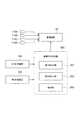
基準座標系とセンサ座標系との対応付けは、図5に示される座標対応付装置300によって行われる。座標対応付装置300は、油圧ショベル1以外の場所に備えられていてもよく、油圧ショベル1に搭載されていてもよい。 The association between the reference coordinate system and the sensor coordinate system is performed by the coordinate
座標対応付装置300には、第1計測装置304と、第2計測装置(計測装置)305とが接続されている。第1計測装置304は、センサユニット100Aの校正用マーカ部130Aと、センサユニット100Aにおける物体検出センサ110Aの設置位置及び姿勢とを計測する。具体的には、第1計測装置304は、校正用マーカ部130Aとして、3以上の校正用マーカ131Aを計測する。第1計測装置304は、物体検出センサ110Aの設置位置及び姿勢として、センサ取付板121Aの上面と、ピン123Aとを計測する。なお、校正用マーカ131Aは、少なくとも3つの校正用マーカ131Aがセンサ取付板121Aの上面及びピン123Aと同時に計測される位置及び向きに設けられている。 The
第1計測装置304は、他のセンサユニット100B〜100Dについても同様に、校正用マーカ部130B〜130Dと、物体検出センサ110B〜110Dの設置位置及び姿勢とをそれぞれ計測する。第1計測装置304は、計測結果を座標対応付装置300に入力する。第1計測装置304による計測は、オペレータが行ってもよく、第1計測装置304が自動で行ってもよい。第1計測装置304として、例えば、三次元レーザ計測器が用いられる。 Similarly, the
ここで、第1計測装置304による計測は、物体検出センサ110A等がセンサ取付板121A等に取り付けられていない状態で行われる。また、第1計測装置304による計測は、取付冶具120A等がアーム13に取り付けられていない状態で行われてもよく、取付冶具120A等がアーム13に取り付けられた状態で行われてもよい。 Here, the measurement by the
第2計測装置305は、センサユニット100Aの校正用マーカ部130Aと、アーム13に設けられた基準マーカ部200Aとを計測する。具体的には、第2計測装置305は、校正用マーカ部130Aとして、3以上の校正用マーカ131Aを計測する。第2計測装置305は、基準マーカ部200Aとして、3以上の基準マーカ201Aを計測する。なお、本実施形態では、基準マーカ部200Aは3つの基準マーカ201Aによって構成されているため、第2計測装置305は、3つ全ての基準マーカ201Aを計測する。 The
また、基準マーカ部200Aは、第2計測装置305が校正用マーカ部130Aを計測するときに、少なくとも3以上の基準マーカ201Aが校正用マーカ部130Aとともに計測される方向を向いている。なお、本実施形態では、基準マーカ部200Aは3つの基準マーカ201Aによって構成されているため、3つ全ての基準マーカ201Aが校正用マーカ部130Aとともに計測される方向を向いている。すなわち、3つの基準マーカ201Aと3以上の校正用マーカ131Aとが1つの視点から視認可能に設けられている。 Further, the
第2計測装置305は、他のセンサユニット100B〜100Dについても同様に、校正用マーカ部130B〜130Dと、アーム13に設けられた基準マーカ部200B〜200Dとをそれぞれ計測する。第2計測装置305は、基準マーカ部200Bとして3つ全ての基準マーカ201Bを計測し、基準マーカ部200Cとして3つ全ての基準マーカ201Cを計測し、基準マーカ部200Dとして3つ全ての基準マーカ201Dを計測する。 Similarly, the
また、基準マーカ部200Bは、第2計測装置305が校正用マーカ部130Bを計測するときに、3つ全ての基準マーカ201Bが校正用マーカ部130Bとともに計測される方向を向いている。基準マーカ部200Cは、第2計測装置305が校正用マーカ部130Cを計測するときに、3つ全ての基準マーカ201Cが校正用マーカ部130Cとともに計測される方向を向いている。基準マーカ部200Dは、第2計測装置305が校正用マーカ部130Dを計測するときに、3つ全ての基準マーカ201Dが校正用マーカ部130Dとともに計測される方向を向いている。 Further, the
このように、アーム13には、3つの基準マーカ201A、3つの基準マーカ201B、3つの基準マーカ201C、及び3つの基準マーカ201Dの合計12個の基準マーカが設置されている。これらの基準マーカのうち、3つの基準マーカ201Aが、第2計測装置305によって校正用マーカ部130Aとともに計測される方向を向いている。同様に、これらの基準マーカ201A〜201Dのうち、3つの基準マーカ201Bが、第2計測装置305によって校正用マーカ部130Bとともに計測される方向を向いている。これらの基準マーカ201A〜201Dのうち、3つの基準マーカ201Cが、第2計測装置305によって校正用マーカ部130Cとともに計測される方向を向いている。これらの基準マーカ201A〜201Dのうち、3つの基準マーカ201Dが、第2計測装置305によって校正用マーカ部130Dとともに計測される方向を向いている。 As described above, a total of 12 reference markers, three
第2計測装置305は、計測結果を座標対応付装置300に入力する。第2計測装置305による計測は、オペレータが行ってもよく、第2計測装置305が自動で行ってもよい。第2計測装置305として、例えば、トータルステーション等の測量機器が用いられる。 The
第2計測装置305は、移動可能であり、例えば、校正用マーカ部130A及び基準マーカ部200Aを計測する場合の位置とは異なる位置から、校正用マーカ部130B及び基準マーカ部200Bを計測してもよい。第2計測装置305が地上に固定されている場合、計測の対象とする校正用マーカ部及び基準マーカ部が計測範囲内に入るように、例えば、油圧ショベル1が移動させられる、又はアーム13等が揺動させられてもよい。 The
座標対応付装置300は、物理的には、CPU(Central Processing Unit)、主記憶装置であるRAM(Random Access Memory)及びROM(Read Only Memory)、他の機器との間の通信を行う通信モジュール、並びにハードディスク等の補助記憶装置等のハードウェアを備えるコンピュータとして構成される。座標対応付装置300は、複数のコンピュータユニットによって構成されていてもよい。 The
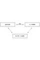
座標対応付装置300は、機能的には、第1対応付部301と、第2対応付部302と、統合部303とを有している。第1対応付部301は、第1計測装置304の計測結果に基づいて、図6に示されるように、物体検出センサ110A〜110Dのセンサ座標系と、校正用マーカ部130A〜130Dによって定義される校正用マーカ座標系とをそれぞれ対応付ける。 The coordinate-corresponding
具体的には、第1対応付部301は、センサ取付板121Aの上面とピン123Aとの計測結果に基づいて、物体検出センサ110Aのセンサ座標系を算出する。第1対応付部301は、校正用マーカ部130Aの計測結果に基づいて、校正用マーカ部130Aによって定義される校正用マーカ座標系を算出する。第1対応付部301は、算出した物体検出センサ110Aのセンサ座標系と、校正用マーカ部130Aによって定義される校正用マーカ座標系とを対応付ける。 Specifically, the first
また、第1対応付部301は、センサ取付板121Bの上面とピン123Bとの計測結果に基づいて、物体検出センサ110Bのセンサ座標系を算出する。第1対応付部301は、校正用マーカ部130Bの計測結果に基づいて、校正用マーカ部130Bによって定義される校正用マーカ座標系を算出する。第1対応付部301は、算出した物体検出センサ110Bのセンサ座標系と、校正用マーカ部130Bによって定義される校正用マーカ座標系とを対応付ける。 Further, the first
同様に、第1対応付部301は、物体検出センサ110Cのセンサ座標系と校正用マーカ部130Cの校正用マーカ座標系とを算出し、算出した座標系同士を対応付ける。第1対応付部301は、物体検出センサ110Dのセンサ座標系と校正用マーカ部130Dの校正用マーカ座標系とを算出し、算出した座標系同士を対応付ける。 Similarly, the
第2対応付部302は、第2計測装置305の計測結果に基づいて、図6に示されるように、校正用マーカ部130A〜130Dによって定義される校正用マーカ座標系と、基準マーカ部200A〜200Dによって定義される基準座標系とをそれぞれ対応付ける。 The second
具体的には、第2対応付部302は、校正用マーカ部130Aの計測結果に基づいて、校正用マーカ部130Aによって定義される校正用マーカ座標系を算出する。第2対応付部302は、基準マーカ部200Aの計測結果に基づいて基準座標系を算出する。第2対応付部302は、算出した校正用マーカ部130Aによって定義される校正用マーカ座標系と、基準座標系とを対応付ける。 Specifically, the second
また、第2対応付部302は、校正用マーカ部130Bの計測結果に基づいて、校正用マーカ部130Bによって定義される校正用マーカ座標系を算出する。第2対応付部302は、基準マーカ部200Bの計測結果に基づいて基準座標系を算出する。第2対応付部302は、算出した校正用マーカ部130Bによって定義される校正用マーカ座標系と、基準座標系とを対応付ける。 Further, the second
同様に、第2対応付部302は、校正用マーカ部130Cの校正用マーカ座標系と基準座標系とを算出し、算出した座標系同士を対応付ける。第2対応付部302は、校正用マーカ部130Dの校正用マーカ座標系と基準座標系とを算出し、算出した座標系同士を対応付ける。 Similarly, the
ここで、第1対応付部301で対応付けられた対応付け結果と、第2対応付部302で対応付けられた対応付け結果とは校正用マーカ座標系が共通している。このため、統合部303は、第1対応付部301で対応付けられたセンサ座標系及び校正用マーカ座標系と、第2対応付部302で対応付けられた校正用マーカ座標系及び基準座標系とを統合することによって、センサ座標系と基準座標系とを対応付ける。 Here, the proofreading marker coordinate system is common to the association result associated with the first
具体的には、統合部303は、物体検出センサ110Aのセンサ座標系及び校正用マーカ部130Aによって定義される校正用マーカ座標系の対応付け結果と、校正用マーカ部130Aによって定義される校正用マーカ座標系及び基準座標系の対応付け結果とを統合することによって、物体検出センサ110Aのセンサ座標系と基準座標系とを対応付ける。また、統合部303は、物体検出センサ110Bのセンサ座標系及び校正用マーカ部130Bによって定義される校正用マーカ座標系の対応付け結果と、校正用マーカ部130Bによって定義される校正用マーカ座標系及び基準座標系の対応付け結果とを統合することによって、物体検出センサ110Bのセンサ座標系と基準座標系とを対応付ける。 Specifically, the
同様に、統合部303は、物体検出センサ110Cのセンサ座標系と基準座標系とを対応付け、物体検出センサ110Dのセンサ座標系と基準座標系とを対応付ける。 Similarly, the
座標対応付装置300によって行われた基準座標系とセンサ座標系との対応付け結果は、監視装置20に入力され、監視装置20における障害物等の監視に用いられる。 The result of associating the reference coordinate system with the sensor coordinate system performed by the coordinate-corresponding
次に、座標対応付装置300、第1計測装置304、及び第2計測装置305を用いて行われる座標系統合方法の処理の流れについて説明する。図7に示されるように、第1計測装置304は、校正用マーカ部130A〜130Dと、物体検出センサ110A〜110Dの設置位置及び姿勢とをそれぞれ計測する(S101:第1計測工程)。第1対応付部301は、第1計測工程の計測結果に基づいて、物体検出センサ110A〜110Dのセンサ座標系と、校正用マーカ部130A〜130Dによって定義される校正用マーカ座標系とをそれぞれ対応付ける(S102:第1対応付け工程)。 Next, the flow of processing of the coordinate system integration method performed by using the coordinate-corresponding
第2計測装置305は、校正用マーカ部130A〜130Dと、基準マーカ部200A〜200Dとをそれぞれ計測する(S103:第2計測工程)。第2対応付部302は、第2計測工程の計測結果に基づいて、校正用マーカ部130A〜130Dによって定義される校正用マーカ座標系と、基準マーカ部200A〜200Dによって定義される基準座標系とをそれぞれ対応付ける(S104:第2対応付工程)。統合部303は、第1対応付工程での対応付け結果と第2対応付工程での対応付け結果とを統合し、物体検出センサ110A〜110Dのセンサ座標系と基準座標系とをそれぞれ対応付ける(S105:統合工程)。 The
以上のように、本実施形態の座標系統合方法によれば、第1計測工程において第1計測装置304を用いて、校正用マーカ部130A〜130Dと物体検出センサ110A〜110Dの設置位置及び姿勢とがそれぞれ計測されている。第2計測工程において第2計測装置305を用いて、校正用マーカ部130A〜130Dと基準マーカ部200A〜200Dとがそれぞれ計測されている。すなわち、第1計測装置304及び第2計測装置305の計測結果に基づいて、物体検出センサ110A〜110Dのセンサ座標系と基準座標系とが対応付けられており、物体検出センサ110A〜110Dの検出結果は用いられていない。従って、この座標系統合方法では、物体検出センサ110A〜110Dの検出精度に依存することなく、油圧ショベル1の基準座標系と物体検出センサ110A〜110Dのセンサ座標系とをそれぞれ対応付けることができる。 As described above, according to the coordinate system integration method of the present embodiment, the installation positions and orientations of the
基準マーカ201Aは、校正用マーカ部130Aとともに第2計測装置305によって計測される方向を向いている。同様に、基準マーカ201B〜201Dは、それぞれ校正用マーカ部130B〜130Dとともに第2計測装置305によって計測される方向を向いている。この場合、例えば、物体検出センサ110Aと物体検出センサ110Bとが異なる位置に設けられていても、第2計測工程において校正用マーカ部130Aと基準マーカ201Aとを計測でき、校正用マーカ部130Bと基準マーカ201Bとを計測できる。また、本実施形態の座標系統合方法では、物体検出センサ110A〜110Dのように複数の物体検出センサが設けられていても、それぞれの物体検出センサ110A〜110Dのセンサ座標系を基準座標系に対応付けることができる。 The
物体検出センサ110A〜110Dは、アーム13の周囲に複数のレーザ光を照射することによって物体を検出するセンサである。この場合、例えば、この物体検出センサ110A〜110Dによって基準マーカ201A〜201Dを検出する場合、レーザ光の照射の間隔によっては201A〜201Dが検出されないことが考えられる。しかしながら、本実施形態の座標系統合方法では、物体検出センサ110A〜110Dの検出結果を用いずにセンサ座標系と基準座標系とを対応付けることができるため、物体検出センサ110A〜110Dの検出精度に依存することなく座標系の対応付けを行うことができる。 The
油圧ショベル1では、例えば、3つの基準マーカ201Aと3以上の校正用マーカ131Aとが1の地点から視認できる。これにより、校正用マーカ131Aと基準マーカ201Aとを計測することで、センサ座標系と基準座標系との対応付けが可能となる。すなわち、物体検出センサ110A〜110Dの検出結果を用いることなく、センサ座標系と基準座標系とが対応付けられる。従って、この油圧ショベル1では、物体検出センサ110A〜110Dの検出精度に依存することなく、アーム13に設定された基準座標系と物体検出センサ110A〜110Dのセンサ座標系とを対応付けることができる。 In the hydraulic excavator 1, for example, three
以上、本開示の実施形態について説明したが、本開示は、上記実施形態に限定されるものではない。例えば、四角柱状に形成されたアーム13に基準マーカ201A等を設置したが、図8に示されるように、円柱形状のアーム15に基準マーカ部200を設けてもよい。この場合、基準マーカ部200を構成する複数の基準マーカ201は、アーム15の外周面において所定の角度ごとにそれぞれ設置されている。所定の角度ごとに設置された複数の基準マーカ201の組は、アーム15の軸方向において複数設けられている。基準マーカ201は、基準座標系を定義している。3つの基準マーカ201に基づいて三次元座標系を導く方法としては、周知の方法を用いることができる。例えば、所定の角度ごとに設置された基準マーカ201の組において、3つの基準マーカ201から円形の面を定義し、面の法線を1つ目の軸とする。円形の面の中心と所定の基準マーカ201を通る直線を2つ目の軸とする。そして、これらの2つの軸に直交する線を3つ目の軸とすることができる。すなわち、複数の基準マーカ201のうち、周方向に並ぶ少なくとも3つの基準マーカ201が3、第2計測装置305によって計測可能に配置されていればよい。 Although the embodiments of the present disclosure have been described above, the present disclosure is not limited to the above embodiments. For example, although the
実施形態では、アーム13の軸に基づいて基準座標系が設定される場合を例に説明したが、基準座標系はアーム13の軸に基づいて設定されることに限定されない。油圧ショベル1に対して適宜の位置に基準座標系が定められていればよい。 In the embodiment, the case where the reference coordinate system is set based on the axis of the
図7では、第1計測工程(S101)及び第1対応付工程(S102)の後に、第2計測工程(S103)及び第2対応付工程(S104)を行ったが、第2計測工程及び第2対応付工程の後に、第1計測工程及び第1対応付工程を行ってもよい。 In FIG. 7, after the first measurement step (S101) and the first correspondence step (S102), the second measurement step (S103) and the second correspondence step (S104) were performed, but the second measurement step and the second correspondence step were performed. 2 After the corresponding step, the first measurement step and the first correspondence step may be performed.
また、例えば、物体検出センサ110Aの設置位置及び姿勢と校正用マーカ131Aとの位置関係が、加工の精度によって定まるなど既知の場合がある。或いは、校正用マーカ131Aが物体検出センサ110Aに直接設置されることにより、物体検出センサ110Aの設置位置及び姿勢と校正用マーカ131Aとの位置関係が、既知となっていてもよい。すなわち、校正用マーカ部130Aによって定義される座標系が、物体検出センサ110Aのセンサ座標系となる。この場合、第1計測装置304を用いた第1計測工程が不要となる。従って、第2計測装置305を用いて校正用マーカ部130Aと基準マーカ部200Aとを計測し(計測工程)、この計測結果を統合部303が統合するだけで(統合工程)、校正用マーカ部130Aによって定義される物体検出センサ110Aのセンサ座標系と基準マーカ部200Aによって定義される基準座標系とを対応付けることができる。物体検出センサ110B〜110Dについても、物体検出センサ110B〜110Dの設置位置及び姿勢と、校正用マーカ部130Bを構成する校正用マーカ131B及び校正用マーカ部130C,130Dを構成する各校正用マーカとの位置関係が既知の場合、第1計測装置304を用いた第1計測工程が不要となる。この場合には、第1計測工程を行うことなく、物体検出センサ110A〜110Dのセンサ座標系と基準座標系とを対応付けることができる。 Further, for example, there are cases where the installation position and orientation of the
センサユニット100A等をアーム13に取り付けたが、アーム13以外の外所にセンサユニット100A等が取り付けられていてもよい。また、物体検出センサ110A等のセンサ座標系を対応付ける対象装置として油圧ショベル1を用いたが、油圧ショベル1に限定されない。例えば、アンローダ、油圧ショベル1以外の建設機械、所定の作業等を行う重機などが対象装置とされてもよい。 Although the
例えば、センサ取付板121Aの上面及びピン123Aによって物体検出センサ110Aのセンサ座標系を特定したが、物体検出センサ110Aの表面に設置されたマーク(センサ座標特定部)等に基づいて、センサ座標系が特定されてもよい。 For example, the sensor coordinate system of the
基準マーカ部200Aは、3つの基準マーカ201Aによって構成されていたが、4つ以上の基準マーカ201Aによって構成されていてもよい。この場合、4つ以上の基準マーカ201Aのうち少なくとも3つ以上の基準マーカ201Aが、第2計測装置305によって計測可能に配置されていればよい。そして、第2計測装置305によって計測された3つの基準マーカ201Aを用いて基準座標系が導かれてもよく、4つ以上の基準マーカ201Aを用いて周知の方法によって基準座標系が導かれてもよい。基準マーカ部200B〜200Dも同様に、4つ以上の基準マーカ201B〜201Dによってそれぞれ構成されていてもよい。 The
実施形態では、3つの校正用マーカ131Aに基づいて校正用マーカ座標系を導く例を示したが、4つ以上の校正用マーカ131Aに基づいて校正用マーカ座標系が導かれてもよい。校正用マーカ部130Bを構成する校正用マーカ131B及び校正用マーカ部130C,130Dを構成する各校正用マーカについても同様に、4つ以上の校正用マーカに基づいてそれぞれ校正用マーカ座標系が導かれてもよい。 In the embodiment, an example of deriving the calibration marker coordinate system based on three
本開示によれば、物体検出センサの検出精度に依存することなく、対象装置の基準座標系と物体検出センサのセンサ座標系とを対応付けることができる。 According to the present disclosure, it is possible to associate the reference coordinate system of the target device with the sensor coordinate system of the object detection sensor without depending on the detection accuracy of the object detection sensor.
1 油圧ショベル(対象装置、柱状体を備える装置)
13 アーム(柱状体)
110A 物体検出センサ(第1物体検出センサ)
110B 物体検出センサ(第2物体検出センサ)
110C,110D 物体検出センサ
120A 取付冶具(第1取付冶具)
120B 取付冶具(第2取付冶具)
121A センサ取付板(センサ座標特定部、第1センサ座標特定部)
123A ピン(センサ座標特定部、第1センサ座標特定部)
121B センサ取付板(センサ座標特定部、第2センサ座標特定部)
123B ピン(センサ座標特定部、第2センサ座標特定部)
131A 校正用マーカ(第1校正用マーカ)
131B 校正用マーカ(第2校正用マーカ)
201,201A〜201D 基準マーカ
304 第1計測装置
305 第2計測装置(計測装置)1 Hydraulic excavator (target device, device with columnar body)
13 Arm (columnar body)
110A object detection sensor (first object detection sensor)
110B object detection sensor (second object detection sensor)
110C, 110D
120B mounting jig (second mounting jig)
121A Sensor mounting plate (sensor coordinate identification part, first sensor coordinate identification part)
123A pin (sensor coordinate identification part, first sensor coordinate identification part)
121B sensor mounting plate (sensor coordinate identification part, second sensor coordinate identification part)
123B pin (sensor coordinate identification part, second sensor coordinate identification part)
131A Calibration marker (1st calibration marker)
131B Calibration marker (second calibration marker)
201, 201A to
Claims (5)
Translated fromJapanese前記物体検出センサを前記対象装置に取り付ける取付冶具又は前記物体検出センサに設けられるとともに前記センサ座標系を定義するセンサ座標特定部と、前記取付冶具に設置されるとともに校正用マーカ座標系を定義する3以上の校正用マーカと、を第1計測装置によって計測する第1計測工程と、
前記第1計測工程の計測結果に基づいて、前記センサ座標特定部によって定義される前記センサ座標系と、前記校正用マーカによって定義される校正用マーカ座標系と、を対応付ける第1対応付工程と、
3以上の前記校正用マーカと、前記対象装置に設置されるとともに前記基準座標系を定義する3以上の基準マーカと、を第2計測装置によって計測する第2計測工程と、
前記第2計測工程の計測結果に基づいて、前記校正用マーカによって定義される前記校正用マーカ座標系と、前記基準マーカによって定義される前記基準座標系とを対応付ける第2対応付工程と、
前記第1対応付工程で対応付けられた前記センサ座標系及び前記校正用マーカ座標系と、前記第2対応付工程で対応付けられた前記校正用マーカ座標系及び前記基準座標系と、に基づいて、前記センサ座標系と前記基準座標系とを対応付ける統合工程と、を含む座標系統合方法。A coordinate system integration method that associates a sensor coordinate system of an object detection sensor attached to a target device with an object around the target device with a reference coordinate system preset for the target device.
A mounting jig for attaching the object detection sensor to the target device or a sensor coordinate specifying unit provided on the object detection sensor and defining the sensor coordinate system, and a marker coordinate system for calibration installed on the mounting jig are defined. The first measurement step of measuring three or more calibration markers by the first measuring device, and
Based on the measurement result of the first measurement step, the first correspondence step of associating the sensor coordinate system defined by the sensor coordinate identification unit with the calibration marker coordinate system defined by the calibration marker. ,
A second measurement step of measuring three or more of the calibration markers and three or more reference markers installed in the target device and defining the reference coordinate system by the second measuring device.
Based on the measurement result of the second measurement step, the second correspondence step of associating the calibration marker coordinate system defined by the calibration marker with the reference coordinate system defined by the reference marker.
Based on the sensor coordinate system and the calibration marker coordinate system associated in the first correspondence step, and the calibration marker coordinate system and the reference coordinate system associated in the second correspondence step. A coordinate system integration method including an integration step of associating the sensor coordinate system with the reference coordinate system.
前記取付冶具は、前記第1物体検出センサを前記対象装置に取り付ける第1取付冶具と、前記第2物体検出センサを前記対象装置に取り付ける第2取付冶具と、を含み、
前記センサ座標特定部は、前記第1取付冶具又は前記第1物体検出センサに設けられるとともに前記第1物体検出センサの第1センサ座標系を定義する第1センサ座標特定部と、前記第2取付冶具又は前記第2物体検出センサに設けられるとともに前記第2物体検出センサの第2センサ座標系を定義する第2センサ座標特定部と、を含み、
前記校正用マーカは、前記第1取付冶具に設置されるとともに第1校正用マーカ座標系を定義する3以上の第1校正用マーカと、前記第2取付冶具に設置されるとともに第2校正用マーカ座標系を定義する3以上の第2校正用マーカと、を含み、
前記基準マーカは、前記対象装置に3以上設置され、前記第2計測装置が3以上の前記第1校正用マーカを計測するときに少なくとも3以上の前記基準マーカが前記第1校正用マーカとともに計測される方向を向き、前記第2計測装置が3以上の前記第2校正用マーカを計測するときに少なくとも3以上の前記基準マーカが前記第2校正用マーカとともに計測される方向を向き、
前記第1計測工程では、前記第1センサ座標特定部と3以上の前記第1校正用マーカとを前記第1計測装置によって計測し、前記第2センサ座標特定部と3以上の前記第2校正用マーカとを前記第1計測装置によって計測し、
前記第1対応付工程では、前記第1センサ座標特定部によって定義される前記第1センサ座標系と前記第1校正用マーカによって定義される前記第1校正用マーカ座標系とを対応付け、前記第2センサ座標特定部によって定義される前記第2センサ座標系と前記第2校正用マーカによって定義される前記第2校正用マーカ座標系とを対応付け、
前記第2計測工程では、3以上の前記第1校正用マーカと3以上の前記基準マーカとを前記第2計測装置によって計測し、3以上の前記第2校正用マーカと3以上の前記基準マーカとを前記第2計測装置によって計測し、
前記第2対応付工程では、前記第1校正用マーカによって定義される前記第1校正用マーカ座標系と前記基準マーカによって定義される前記基準座標系とを対応付け、前記第2校正用マーカによって定義される前記第2校正用マーカ座標系と前記基準マーカによって定義される前記基準座標系とを対応付け、
前記統合工程では、
前記第1対応付工程で対応付けられた前記第1センサ座標系及び前記第1校正用マーカ座標系と、第2対応付工程で対応付けられた前記第1校正用マーカ座標系及び前記基準座標系と、に基づいて、前記第1センサ座標系と前記基準座標系とを対応付け、
前記第1対応付工程で対応付けられた前記第2センサ座標系及び前記第2校正用マーカ座標系と、第2対応付工程で対応付けられた前記第2校正用マーカ座標系及び前記基準座標系と、に基づいて、前記第2センサ座標系と前記基準座標系とを対応付ける、請求項1に記載の座標系統合方法。The object detection sensor includes a first object detection sensor and a second object detection sensor.
The mounting jig includes a first mounting jig that attaches the first object detection sensor to the target device, and a second mounting jig that attaches the second object detection sensor to the target device.
The sensor coordinate identification unit is provided on the first attachment jig or the first object detection sensor, and defines the first sensor coordinate system of the first object detection sensor, the first sensor coordinate identification unit, and the second attachment. Includes a second sensor coordinate identification unit that is provided on the jig or the second object detection sensor and defines the second sensor coordinate system of the second object detection sensor.
The calibration markers are installed on the first mounting jig and have three or more first calibration markers that define the coordinate system of the first calibration marker, and are installed on the second mounting jig and are used for the second calibration. Includes three or more second calibration markers that define the marker coordinate system.
Three or more reference markers are installed in the target device, and when the second measuring device measures three or more of the first calibration markers, at least three or more of the reference markers measure together with the first calibration marker. When the second measuring device measures three or more of the second calibration markers, at least three or more of the reference markers are oriented in the direction of being measured together with the second calibration marker.
In the first measurement step, the first sensor coordinate identification unit and three or more first calibration markers are measured by the first measurement device, and the second sensor coordinate identification unit and three or more second calibration markers are measured. The marker is measured by the first measuring device.
In the first corresponding step, the first sensor coordinate system defined by the first sensor coordinate identification unit and the first calibration marker coordinate system defined by the first calibration marker are associated with each other. The second sensor coordinate system defined by the second sensor coordinate identification unit is associated with the second calibration marker coordinate system defined by the second calibration marker.
In the second measurement step, three or more of the first calibration markers and three or more of the reference markers are measured by the second measuring device, and three or more of the second calibration markers and three or more of the reference markers are measured. And are measured by the second measuring device,
In the second corresponding step, the first calibration marker coordinate system defined by the first calibration marker is associated with the reference coordinate system defined by the reference marker, and the second calibration marker is used. The defined second calibration marker coordinate system is associated with the reference coordinate system defined by the reference marker.
In the integration process,
The first sensor coordinate system and the first calibration marker coordinate system associated with the first correspondence step, and the first calibration marker coordinate system and the reference coordinate associated with the second correspondence step. Based on the system, the first sensor coordinate system and the reference coordinate system are associated with each other.
The second sensor coordinate system and the second calibration marker coordinate system associated with the first correspondence step, and the second calibration marker coordinate system and the reference coordinate associated with the second correspondence step. and the system, based on, associating with the reference coordinate system and the second sensor coordinate system, the coordinate system integrated process according to claim1.
前記第2対応付工程では、前記第2計測装置によって計測された3つの前記基準マーカによって三次元の前記基準座標系を導く、請求項1〜4のいずれか一項に記載の座標系統合方法。 The coordinate system integration method according to any one of claims 1 to 4, wherein in the second corresponding step, the three-dimensional reference coordinate system is derived by the three reference markers measured by the second measuring device. ..
Applications Claiming Priority (3)
| Application Number | Priority Date | Filing Date | Title |
|---|---|---|---|
| JP2018017053 | 2018-02-02 | ||
| JP2018017053 | 2018-02-02 | ||
| PCT/JP2019/002949WO2019151238A1 (en) | 2018-02-02 | 2019-01-29 | Coordinate system integration method, and device provided with columnar body |
Publications (2)
| Publication Number | Publication Date |
|---|---|
| JPWO2019151238A1 JPWO2019151238A1 (en) | 2020-12-03 |
| JP6912604B2true JP6912604B2 (en) | 2021-08-04 |
Family
ID=67478111
Family Applications (1)
| Application Number | Title | Priority Date | Filing Date |
|---|---|---|---|
| JP2019569124AActiveJP6912604B2 (en) | 2018-02-02 | 2019-01-29 | Coordinate system integration method and device with columnar body |
Country Status (3)
| Country | Link |
|---|---|
| JP (1) | JP6912604B2 (en) |
| TW (1) | TWI702851B (en) |
| WO (1) | WO2019151238A1 (en) |
Families Citing this family (2)
| Publication number | Priority date | Publication date | Assignee | Title |
|---|---|---|---|---|
| EP4033035A1 (en) | 2021-01-20 | 2022-07-27 | Volvo Construction Equipment AB | A system and method therein for remote operation of a working machine comprising a tool |
| WO2025197457A1 (en)* | 2024-03-22 | 2025-09-25 | 日立建機株式会社 | System for calibrating construction machine and method for calibrating construction machine |
Family Cites Families (16)
| Publication number | Priority date | Publication date | Assignee | Title |
|---|---|---|---|---|
| US5764511A (en)* | 1995-06-20 | 1998-06-09 | Caterpillar Inc. | System and method for controlling slope of cut of work implement |
| JP4284765B2 (en)* | 1999-07-27 | 2009-06-24 | 株式会社豊田中央研究所 | Robot hand position measuring device |
| JP2002107128A (en)* | 2000-10-02 | 2002-04-10 | Sanyo Electric Co Ltd | Shape-measuring apparatus |
| JP2003282238A (en)* | 2002-03-25 | 2003-10-03 | Pioneer Electronic Corp | Organic electroluminescent display panel and manufacturing method |
| WO2008107715A2 (en)* | 2007-03-05 | 2008-09-12 | Absolute Robotics Limited | Determining positions |
| JP2009199247A (en)* | 2008-02-20 | 2009-09-03 | Fuji Xerox Co Ltd | Object recognition apparatus, indicating device and program |
| JP2010025759A (en)* | 2008-07-18 | 2010-02-04 | Fuji Xerox Co Ltd | Position measuring system |
| DE102008062624A1 (en)* | 2008-12-17 | 2010-06-24 | Kuka Roboter Gmbh | Hand-held device and method for detecting the spatial position of an operating point of a manipulator |
| JP5843531B2 (en)* | 2010-09-27 | 2016-01-13 | 株式会社ミツトヨ | Coordinate measuring head unit and coordinate measuring machine |
| US9168654B2 (en)* | 2010-11-16 | 2015-10-27 | Faro Technologies, Inc. | Coordinate measuring machines with dual layer arm |
| JP2012233353A (en)* | 2011-05-02 | 2012-11-29 | Komatsu Ltd | Calibration system for hydraulic shovel and calibration method for the hydraulic shovel |
| WO2015089403A1 (en)* | 2013-12-12 | 2015-06-18 | The Regents Of The University Of Michigan | Estimating three-dimensional position and orientation of articulated machine using one or more image-capturing devices and one or more markers |
| JP5736622B1 (en)* | 2014-05-01 | 2015-06-17 | 機械設計中畑株式会社 | Detection device and operation control of manipulator equipped with the device |
| JP2016048172A (en)* | 2014-08-27 | 2016-04-07 | 株式会社トプコン | Image processing apparatus, image processing method, and program |
| ES2967886T3 (en)* | 2014-09-19 | 2024-05-06 | Hexagon Metrology Inc | Multi-mode portable coordinate measuring machine |
| JP6126067B2 (en)* | 2014-11-28 | 2017-05-10 | ファナック株式会社 | Collaborative system with machine tool and robot |
- 2019
- 2019-01-29JPJP2019569124Apatent/JP6912604B2/enactiveActive
- 2019-01-29WOPCT/JP2019/002949patent/WO2019151238A1/ennot_activeCeased
- 2019-02-01TWTW108104205Apatent/TWI702851B/enactive
Also Published As
| Publication number | Publication date |
|---|---|
| JPWO2019151238A1 (en) | 2020-12-03 |
| WO2019151238A1 (en) | 2019-08-08 |
| TWI702851B (en) | 2020-08-21 |
| TW201937920A (en) | 2019-09-16 |
Similar Documents
| Publication | Publication Date | Title |
|---|---|---|
| EP3450636B1 (en) | Construction machine | |
| US11346085B2 (en) | Obstacle detection device of construction machine | |
| CN101322071B (en) | System for projecting flaws and inspection locations and associated method | |
| US20180023946A1 (en) | Laser gauge for robotic calibration and monitoring | |
| JP4218449B2 (en) | Crane operation monitoring system and method | |
| EP2381214B1 (en) | Optical measurement system | |
| US9580885B2 (en) | Swing operating machine and method of controlling swing operating machine | |
| CN110740841B (en) | System | |
| JP5570332B2 (en) | Turning work machine and control method of turning work machine | |
| JP6912604B2 (en) | Coordinate system integration method and device with columnar body | |
| CN108139194A (en) | Sensor device and manipulator device having said sensor device | |
| JP7023813B2 (en) | Work machine | |
| US11454498B2 (en) | Coordinate measuring system | |
| CN112424563A (en) | Multi-dimensional measurement system for accurately calculating position and orientation of dynamic object | |
| JPWO2015137526A1 (en) | Work machine calibration apparatus and work machine parameter calibration method | |
| JP2002181538A (en) | Construction edge position detection device using GPS | |
| US20240018752A1 (en) | Position detection system | |
| JP2002181539A (en) | Position detection method and device using GPS in civil engineering construction machine | |
| EP3002088A2 (en) | Orthogonal positioning instrument, system and method for automatic machines | |
| CN114343848A (en) | A length measurement system of a marker block and a surgical robot system | |
| CN221225019U (en) | Detection system for aerial working machine and aerial working machine | |
| JP7277398B2 (en) | Orientation measurement method for heavy machinery | |
| US20240217781A1 (en) | Peripheral monitoring system for work machine and work machine | |
| JP7707690B2 (en) | Intrusion Detection System | |
| CN108138467B (en) | Control unit for determining the position of an implement in a work machine |
Legal Events
| Date | Code | Title | Description |
|---|---|---|---|
| A621 | Written request for application examination | Free format text:JAPANESE INTERMEDIATE CODE: A621 Effective date:20200603 | |
| A521 | Request for written amendment filed | Free format text:JAPANESE INTERMEDIATE CODE: A821 Effective date:20200603 | |
| A131 | Notification of reasons for refusal | Free format text:JAPANESE INTERMEDIATE CODE: A131 Effective date:20210209 | |
| A521 | Request for written amendment filed | Free format text:JAPANESE INTERMEDIATE CODE: A523 Effective date:20210401 | |
| TRDD | Decision of grant or rejection written | ||
| A01 | Written decision to grant a patent or to grant a registration (utility model) | Free format text:JAPANESE INTERMEDIATE CODE: A01 Effective date:20210629 | |
| A61 | First payment of annual fees (during grant procedure) | Free format text:JAPANESE INTERMEDIATE CODE: A61 Effective date:20210708 | |
| R150 | Certificate of patent or registration of utility model | Ref document number:6912604 Country of ref document:JP Free format text:JAPANESE INTERMEDIATE CODE: R150 | |
| R250 | Receipt of annual fees | Free format text:JAPANESE INTERMEDIATE CODE: R250 | |
| R250 | Receipt of annual fees | Free format text:JAPANESE INTERMEDIATE CODE: R250 | |
| S111 | Request for change of ownership or part of ownership | Free format text:JAPANESE INTERMEDIATE CODE: R313115 |