JP6912226B2 - Manual coating guns and coating stations containing such guns - Google Patents
Manual coating guns and coating stations containing such gunsDownload PDFInfo
- Publication number
- JP6912226B2 JP6912226B2JP2017043623AJP2017043623AJP6912226B2JP 6912226 B2JP6912226 B2JP 6912226B2JP 2017043623 AJP2017043623 AJP 2017043623AJP 2017043623 AJP2017043623 AJP 2017043623AJP 6912226 B2JP6912226 B2JP 6912226B2
- Authority
- JP
- Japan
- Prior art keywords
- coating product
- voltage
- manual gun
- flow rate
- control member
- Prior art date
- Legal status (The legal status is an assumption and is not a legal conclusion. Google has not performed a legal analysis and makes no representation as to the accuracy of the status listed.)
- Active
Links
Images


Classifications
- B—PERFORMING OPERATIONS; TRANSPORTING
- B05—SPRAYING OR ATOMISING IN GENERAL; APPLYING FLUENT MATERIALS TO SURFACES, IN GENERAL
- B05B—SPRAYING APPARATUS; ATOMISING APPARATUS; NOZZLES
- B05B12/00—Arrangements for controlling delivery; Arrangements for controlling the spray area
- B05B12/002—Manually-actuated controlling means, e.g. push buttons, levers or triggers
- B—PERFORMING OPERATIONS; TRANSPORTING
- B05—SPRAYING OR ATOMISING IN GENERAL; APPLYING FLUENT MATERIALS TO SURFACES, IN GENERAL
- B05C—APPARATUS FOR APPLYING FLUENT MATERIALS TO SURFACES, IN GENERAL
- B05C17/00—Hand tools or apparatus using hand held tools, for applying liquids or other fluent materials to, for spreading applied liquids or other fluent materials on, or for partially removing applied liquids or other fluent materials from, surfaces
- B05C17/10—Hand tools for removing partially or for spreading or redistributing applied liquids or other fluent materials, e.g. colour touchers
- B—PERFORMING OPERATIONS; TRANSPORTING
- B05—SPRAYING OR ATOMISING IN GENERAL; APPLYING FLUENT MATERIALS TO SURFACES, IN GENERAL
- B05B—SPRAYING APPARATUS; ATOMISING APPARATUS; NOZZLES
- B05B5/00—Electrostatic spraying apparatus; Spraying apparatus with means for charging the spray electrically; Apparatus for spraying liquids or other fluent materials by other electric means
- B05B5/005—Electrostatic spraying apparatus; Spraying apparatus with means for charging the spray electrically; Apparatus for spraying liquids or other fluent materials by other electric means the high voltage supplied to an electrostatic spraying apparatus being adjustable during spraying operation, e.g. for modifying spray width, droplet size
- B—PERFORMING OPERATIONS; TRANSPORTING
- B05—SPRAYING OR ATOMISING IN GENERAL; APPLYING FLUENT MATERIALS TO SURFACES, IN GENERAL
- B05B—SPRAYING APPARATUS; ATOMISING APPARATUS; NOZZLES
- B05B5/00—Electrostatic spraying apparatus; Spraying apparatus with means for charging the spray electrically; Apparatus for spraying liquids or other fluent materials by other electric means
- B05B5/025—Discharge apparatus, e.g. electrostatic spray guns
- B05B5/0255—Discharge apparatus, e.g. electrostatic spray guns spraying and depositing by electrostatic forces only
- B—PERFORMING OPERATIONS; TRANSPORTING
- B05—SPRAYING OR ATOMISING IN GENERAL; APPLYING FLUENT MATERIALS TO SURFACES, IN GENERAL
- B05B—SPRAYING APPARATUS; ATOMISING APPARATUS; NOZZLES
- B05B5/00—Electrostatic spraying apparatus; Spraying apparatus with means for charging the spray electrically; Apparatus for spraying liquids or other fluent materials by other electric means
- B05B5/025—Discharge apparatus, e.g. electrostatic spray guns
- B05B5/03—Discharge apparatus, e.g. electrostatic spray guns characterised by the use of gas, e.g. electrostatically assisted pneumatic spraying
- B05B5/032—Discharge apparatus, e.g. electrostatic spray guns characterised by the use of gas, e.g. electrostatically assisted pneumatic spraying for spraying particulate materials
- B—PERFORMING OPERATIONS; TRANSPORTING
- B05—SPRAYING OR ATOMISING IN GENERAL; APPLYING FLUENT MATERIALS TO SURFACES, IN GENERAL
- B05B—SPRAYING APPARATUS; ATOMISING APPARATUS; NOZZLES
- B05B5/00—Electrostatic spraying apparatus; Spraying apparatus with means for charging the spray electrically; Apparatus for spraying liquids or other fluent materials by other electric means
- B05B5/025—Discharge apparatus, e.g. electrostatic spray guns
- B05B5/035—Discharge apparatus, e.g. electrostatic spray guns characterised by gasless spraying, e.g. electrostatically assisted airless spraying
- B—PERFORMING OPERATIONS; TRANSPORTING
- B05—SPRAYING OR ATOMISING IN GENERAL; APPLYING FLUENT MATERIALS TO SURFACES, IN GENERAL
- B05B—SPRAYING APPARATUS; ATOMISING APPARATUS; NOZZLES
- B05B5/00—Electrostatic spraying apparatus; Spraying apparatus with means for charging the spray electrically; Apparatus for spraying liquids or other fluent materials by other electric means
- B05B5/025—Discharge apparatus, e.g. electrostatic spray guns
- B05B5/053—Arrangements for supplying power, e.g. charging power
- B—PERFORMING OPERATIONS; TRANSPORTING
- B05—SPRAYING OR ATOMISING IN GENERAL; APPLYING FLUENT MATERIALS TO SURFACES, IN GENERAL
- B05B—SPRAYING APPARATUS; ATOMISING APPARATUS; NOZZLES
- B05B5/00—Electrostatic spraying apparatus; Spraying apparatus with means for charging the spray electrically; Apparatus for spraying liquids or other fluent materials by other electric means
- B05B5/16—Arrangements for supplying liquids or other fluent material
- B—PERFORMING OPERATIONS; TRANSPORTING
- B05—SPRAYING OR ATOMISING IN GENERAL; APPLYING FLUENT MATERIALS TO SURFACES, IN GENERAL
- B05B—SPRAYING APPARATUS; ATOMISING APPARATUS; NOZZLES
- B05B5/00—Electrostatic spraying apparatus; Spraying apparatus with means for charging the spray electrically; Apparatus for spraying liquids or other fluent materials by other electric means
- B05B5/025—Discharge apparatus, e.g. electrostatic spray guns
- B—PERFORMING OPERATIONS; TRANSPORTING
- B05—SPRAYING OR ATOMISING IN GENERAL; APPLYING FLUENT MATERIALS TO SURFACES, IN GENERAL
- B05B—SPRAYING APPARATUS; ATOMISING APPARATUS; NOZZLES
- B05B7/00—Spraying apparatus for discharge of liquids or other fluent materials from two or more sources, e.g. of liquid and air, of powder and gas
- B05B7/02—Spray pistols; Apparatus for discharge
- B05B7/12—Spray pistols; Apparatus for discharge designed to control volume of flow, e.g. with adjustable passages
Landscapes
- Engineering & Computer Science (AREA)
- Mechanical Engineering (AREA)
- Electrostatic Spraying Apparatus (AREA)
- Application Of Or Painting With Fluid Materials (AREA)
- General Engineering & Computer Science (AREA)
- Coating Apparatus (AREA)
Description
Translated fromJapanese本発明は、コーティング用製品を手動で適用するためのガン、及びそのようなガンを含むコーティング用製品を適用するためのステーションに関する。特に、ガンは、紛体形態の塗料のようなコーティング用製品を適用するために設計された、静電紛体を手動で適用するためのガンである。 The present invention relates to a gun for manually applying a coating product and a station for applying a coating product containing such a gun. In particular, guns are guns for the manual application of electrostatic powder, designed for the application of coating products such as powder-form paints.
公知の方法において、そのようなガンは、電力が供給された場合に、特定の電圧/電流特性に従ってコーティング用製品を静電的に帯電するために設計された高電圧ユニットを含む。高電圧ユニットの電圧/電流特性は、高電圧ユニットによって与えられた電圧と電流間の比に相当する。したがって、これは、電流に対する電圧の継時変化を代表する曲線である。典型的に、その特性は、負の傾きを持つ直線である。この高電圧ユニットは、低電圧ケーブルと称される電気ケーブルを通じて低電圧が供給され、それは電気モジュールに接続されている。ガンは、ポンプに接続された管を通じて、コーティング用製品が供給される。このポンプは、制御モジュールによって圧縮空気が供給される。ポンプによってパルス化されたコーティング用製品の流量は、供給された圧縮空気の圧力及び流量に依存する。制御モジュール及び電気モジュールは、しばしば、同一の電空モジュール内でグループ分けされる。 In known methods, such guns include high voltage units designed to electrostatically charge coating products according to specific voltage / current characteristics when powered. The voltage / current characteristics of the high voltage unit correspond to the ratio between the voltage and current given by the high voltage unit. Therefore, this is a curve that represents the change over time of the voltage with respect to the current. Typically, its characteristic is a straight line with a negative slope. This high voltage unit is supplied with a low voltage through an electric cable called a low voltage cable, which is connected to an electric module. The gun is supplied with a coating product through a tube connected to the pump. Compressed air is supplied to this pump by a control module. The flow rate of the coating product pulsed by the pump depends on the pressure and flow rate of the supplied compressed air. Control modules and electrical modules are often grouped within the same electropneumatic module.
電空モジュールは、ユーザーによりコーティング用製品の異なる適用パラメータ、例えば、紛体の流量、適用される高電圧、又はさらに洗浄サイクル、を制御することが可能である制御装置及び表示器を持つインターフェイスを含む。 The electropneumatic module includes an interface with a controller and an indicator that allows the user to control different application parameters of the coating product, such as the flow rate of the powder, the high voltage applied, or even the cleaning cycle. ..
ガンの大部分においては、実際のガンレベルで利用することができる制御装置は極めて少ない。現在トリガーと称される制御部材が存在するのみであり、それは、コーティング用製品の適用を妨げ、高電圧ユニットに電力が供給されない非アクティブ停止構成と、コーティング用製品の適用を妨げず、高電圧ユニットに電力が供給されるアクティブ動作構成との間で、ペインタによって操作可能である。任意選択で、表示器が、設備の一部が作動していること及び/又はトリガーがアクティブ構成にあることをペインタに示すために、ガン上に存在する。 For most cancers, very few controls are available at the actual cancer level. Currently there is only a control member called a trigger, which prevents the application of the coating product and does not interfere with the application of the coating product, the inactive stop configuration in which the high voltage unit is not powered, and the high voltage. It can be operated by the painter to and from the active operating configuration where the unit is powered. Optionally, an indicator is present on the gun to indicate to the painter that part of the equipment is operating and / or the trigger is in the active configuration.
従来技術に係る複数の適用ステーションは、部品の形状にできる限り適応するために、高電圧ユニットの電圧/電流特性を調整することができる。ジェットの性質は、使用される電圧/電流特性に従って変わる。電圧/電流特性を変えるため、ペインタは、電空モジュールに位置したインターフェイスに達するために、タスク(作業)を遮断すべきである。ここで、後者は、時々、塗装されるべき部品から比較的離れて局在化される。したがって、このタイプのステーションは、連続的なコンベヤーを使用する半自動化されたパウダリング(紛体散布)の適用と互換性がなく、ペインタが、例えば、再作業領域に手動で介入する。後者は、実際に、それらの作業ステーションから容易に離れることができない。 The plurality of application stations according to the prior art can adjust the voltage / current characteristics of the high voltage unit in order to adapt as much as possible to the shape of the component. The nature of the jet depends on the voltage / current characteristics used. To change the voltage / current characteristics, the painter should interrupt the task to reach the interface located in the electropneumatic module. Here, the latter is sometimes localized relatively away from the part to be painted. Therefore, this type of station is incompatible with the application of semi-automated powdering using a continuous conveyor, where the painter manually intervenes, for example, in the rework area. The latter, in fact, cannot be easily separated from those work stations.
これらの欠点に対する改善策を見つけるために、複数の高性能な静電ガンは、ガンから直接アクセス可能である適用パラメータを管理する制御装置を含む。例として、これらの制御装置は、紛体流量を管理することができ、電圧/電流特性を調整することができ、又はさらにパージ要求を実行することができる。さらに、複数のガンが、ガンが作動している場合、トリガーが始動された場合、又はさらにガンがパージ相にある場合をペインタに示す機能を有した、状態復帰の表示器を備える。 To find remedies for these shortcomings, multiple high performance electrostatic guns include controls that manage applicable parameters that are directly accessible from the gun. As an example, these controllers can control the powder flow rate, adjust the voltage / current characteristics, or even perform a purge request. Further, the plurality of guns are provided with a state return indicator having a function of indicating to the painter when the gun is operating, when the trigger is activated, or when the gun is in the purge phase.
例えば、欧州特許第1115498号明細書では、紛体コーティングを適用するための手動制御装置を持つガンを開示し、それは、紛体の流量及び高電圧の中からのパラメータの調整を可能とする、2つのボタン「+」と「−」とをそれぞれ備える。両ボタンを同時に押すことで、紛体の流量及び高電圧の中からその他のパラメータを調整することができる。手動ガンは、ガンにコーティング用製品を供給するためのオン/オフタイプの制御部材を含む。説明された実施形態においては、噴射中に、電極がコーティング用粉末を最小の高電圧に帯電する。次いで、この電圧レベルを、同時に両ボタンを押すことによって修正することができる。したがって、電圧/電流特性の調整は、噴射中に、すなわち、制御部材が「オン」の位置にある場合に、実行される必要がある。したがって、同時にボタンを押すということは、制御部材が「オフ」の位置にある場合は、電圧/電流特性を修正することができない。 For example, European Patent No. 1115498 discloses a gun with a manual control device for applying a powder coating, which allows adjustment of parameters from within the flow rate and high voltage of the powder. It has buttons "+" and "-" respectively. By pressing both buttons at the same time, other parameters can be adjusted from the flow rate and high voltage of the powder. The manual gun includes an on / off type control member for supplying the gun with a coating product. In the embodiments described, the electrodes charge the coating powder to a minimum high voltage during injection. This voltage level can then be corrected by pressing both buttons at the same time. Therefore, the adjustment of the voltage / current characteristics needs to be performed during injection, i.e. when the control member is in the "on" position. Therefore, pressing the buttons at the same time cannot correct the voltage / current characteristics when the control member is in the "off" position.
独国特許出願公開第102005017931号明細書では、コーティング用製品を適用するための手動ガンの2つの実施形態を主に開示する。図8の実施形態において、ガンは、後部に、ガンに紛体化したコーティング用製品の流量をそれぞれ増やす又は減らすことができる、2つの制御ボタンを持つフードを含む。ボタンを同時に押すことによって、高電圧ユニットの特性を修正することができる。ボタンとしてのトリガーは、噴射を制御することができる。高電圧ユニットは、ボタンを離した場合は電力が供給されない。 German Patent Application Publication No. 102005017931 primarily discloses two embodiments of a manual gun for applying a coating product. In the embodiment of FIG. 8, the gun includes a hood at the rear with two control buttons capable of increasing or decreasing the flow rate of the coating product powdered into the gun, respectively. By pressing the buttons at the same time, the characteristics of the high voltage unit can be modified. The trigger as a button can control the injection. The high voltage unit is not powered when the button is released.
欧州特許出願公開第2055391号明細書では、把持ハンドルと、噴射を開始する又は遮断するための第1トリガーと、ガンによって適用されるコーティング用製品の流量を増やす又は減らすために使用される第2トリガーとを含む、コーティング用製品を適用するための手動ガンを開示する。ガンはまた、切り替えモードのために使用することができる一方のボタンと、パージ相を開始するために使用することができる他方のボタンとを含む、プッシュボタンを含む。 In European Patent Application Publication No. 2055391, a gripping handle, a first trigger for initiating or blocking injection, and a second used to increase or decrease the flow rate of the coating product applied by the gun. Disclose manual guns for applying coating products, including triggers. The gun also includes a push button, including one button that can be used for the switch mode and the other button that can be used to start the purge phase.
国際公開第01/91914号では、パウダリングを達成するために要求される紛体の流量及び電圧/電流特性を調整することが可能である、手動パウダリングガンを開示する。これらの調整を行うために、ガンは、紛体の流量を調整するためのポテンショメータに関連する、連続調整ボタンを備える。第2調整ボタンは、塗装されるべき部分に係る電圧特性を選択することができる。したがって、特有の調整手段が、コーティング用製品の流量の調整及び電圧/電流特性の調整をするために提供される。別の例は、名称PEMX1の下でWAGNERグループによって販売されるガンに関する。このガンは、高電圧を調整するための手段として制御トリガーを使用する。ガンの制御モジュールがトリガーに及ぼされた2つの閉動作を検出した場合は、電圧/電流特性が変わる。コーティング用製品の流量は、ペインタによって手動でトリガーを多かれ少なかれ後方に動かすことで、調整される。 WO 01/91914 discloses a manual powdering gun capable of adjusting the flow rate and voltage / current characteristics of the powder required to achieve powdering. To make these adjustments, the gun is equipped with a continuous adjustment button associated with a potentiometer for adjusting the flow rate of the powder. The second adjustment button can select the voltage characteristic related to the part to be painted. Therefore, specific adjusting means are provided to adjust the flow rate and voltage / current characteristics of the coating product. Another example relates to a cancer sold by the WAGNER group under the name PEMX1. This gun uses a control trigger as a means to regulate high voltage. If the gun's control module detects two closing actions on the trigger, the voltage / current characteristics change. The flow rate of the coating product is adjusted by manually moving the trigger more or less backwards by the painter.
しかしながら、現在のこのタイプのガンは製造するには高価であり、比較的容積が大きくなり、それによってそれらが人間工学的にあまりならない。これは、ガンに搭載して装填された電気モジュール、例えば、電気導体及びシールド部材が原因である。 However, current types of guns are expensive to manufacture and are relatively bulky, which makes them less ergonomic. This is due to the electrical modules loaded on the gun, such as the electrical conductors and shield members.
したがって、目的は、ガン上でペインタにとって直接アクセスできる制御装置の数、ガンの重量、その容積及びそのコストの間で良好な妥協点を見つけることである。 Therefore, the purpose is to find a good compromise between the number of controls directly accessible to the painter on the gun, the weight of the gun, its volume and its cost.
この目的のために、本発明は、コーティング用製品を適用するための手動ガンに関し、このガンは、電力が供給された場合に、電圧/電流特性に従ってコーティング用製品を静電的に帯電するために設計された高電圧ユニットと、複数の予め調整された電圧/電流特性の中から、製品が静電的に帯電される電圧/電流特性を選択するための調整手段とを含む。このガンはまた、コーティング用製品の適用を妨げ、高電圧ユニットに電力が供給されない非アクティブ構成と、コーティング用製品の適用を妨げず、高電圧ユニットに電力が供給されるアクティブ構成との間で操作可能である、制御部材を含む。本発明によれば、調整手段は、制御部材がアクティブ構成である場合は、ガンによって適用されるコーティング用製品の流量を手動で適用することができ、制御部材が非アクティブ構成である場合は、高電圧ユニットの電圧/電流特性を選択することができる制御ボタンを含む。 To this end, the present invention relates to a manual gun for applying a coating product, because the gun electrostatically charges the coating product according to voltage / current characteristics when powered. It includes a high voltage unit designed in the above and an adjusting means for selecting the voltage / current characteristic in which the product is electrostatically charged from among a plurality of pre-adjusted voltage / current characteristics. The gun also interferes with the application of coating products and is between an inactive configuration where the high voltage unit is not powered and an active configuration which does not interfere with the application of coating products and is powered by the high voltage unit. Includes control members that are operable. According to the present invention, the adjusting means can manually apply the flow rate of the coating product applied by the gun if the control member is in the active configuration and if the control member is in the inactive configuration. Includes a control button that allows the voltage / current characteristics of the high voltage unit to be selected.
本発明によって、電圧/電流特性の切り替え及びコーティング用製品の流量の変更を管理するために使用される電気回路が比較的単純であり、それは、制御ボタンが、制御部材がアクティブ構成にある場合はコーティング用製品の流量に、制御部材が非アクティブ構成にある場合は電圧/電流特性に、の両方に作用するためである。言い換えると、高電圧を調整するために及び適用されるコーティング用製品の流量を調整するために、同一の配線が使用される。このタイプの配線は、従来技術のガンには知られていなく、それにより、しばしば、独立した電気制御回路を提供する。 According to the present invention, the electrical circuit used to control the switching of voltage / current characteristics and the change of flow rate of the coating product is relatively simple, that is, when the control button is in the active configuration of the control member. This is because it affects both the flow rate of the coating product and the voltage / current characteristics when the control member is in an inactive configuration. In other words, the same wiring is used to regulate the high voltage and to regulate the flow rate of the applied coating product. This type of wiring is unknown to prior art guns, thereby often providing an independent electrical control circuit.
本発明の有利であるが任意の態様によれば、ガンは、任意の技術的に許容される組み合わせで考慮される、1つ又は複数の以下の特徴を含むことができる。 According to an advantageous but arbitrary aspect of the invention, the cancer can include one or more of the following features that are considered in any technically acceptable combination:
制御ボタンが、部材がアクティブ構成にある場合はコーティング用製品の流量を増やし、部材が非アクティブ構成にある場合は電圧/電流特性を変えるための第1ボタンと、部材がアクティブ構成にある場合はコーティング用製品の流量を減らし、部材が非アクティブ構成にある場合は電圧/電流特性を変えるための第2ボタンとを含む。 The control button is the first button to increase the flow rate of the coating product when the member is in the active configuration and to change the voltage / current characteristics when the member is in the inactive configuration, and when the member is in the active configuration. Includes a second button to reduce the flow rate of the coating product and change the voltage / current characteristics if the member is in an inactive configuration.
第1ボタンが符号「+」でコーティングされ、第2ボタンが符号「−」でコーティングされる。 The first button is coated with the symbol "+" and the second button is coated with the symbol "-".
ガンが、選択された電圧/電流特性を示すための少なくとも1つの第1表示灯を含む。 The gun includes at least one first indicator light to indicate the selected voltage / current characteristics.
第1表示灯が発光ダイオードであり、その色が選択された電圧/電流特性に従って変わる。 The first indicator light is a light emitting diode whose color changes according to the selected voltage / current characteristics.
第1表示灯が点滅発光ダイオードであり、その点滅頻度が選択された電圧/電流特性に依存する。 The first indicator light is a blinking light emitting diode, the blinking frequency of which depends on the selected voltage / current characteristic.
第1表示灯が、制御部材の構成に関係なく、点灯したままである。 The first indicator light remains lit regardless of the configuration of the control member.
ガンが、コーティング用製品の流量の変化を示すための第2表示灯を含む。 The gun includes a second indicator light to indicate changes in the flow rate of the coating product.
ガンが、コーティング用製品の最大又は最小の流量が得られた場合を示すための第3表示灯を含む。 The gun includes a third indicator light to indicate when the maximum or minimum flow rate of the coating product has been obtained.
第1表示灯及び第2表示灯が、それぞれ、選択された電圧/電流特性又はコーティング用製品の流量を常に表示するために構成された棒グラフである。 The first indicator light and the second indicator light are bar graphs configured to constantly display the selected voltage / current characteristics or the flow rate of the coating product, respectively.
第1表示灯及び第2表示灯が、制御部材が非アクティブ構成にある場合は選択された電圧/電流特性を表示するために構成された同一の棒グラフであり、又は、制御部材がアクティブ構成にある場合はコーティング用製品の流量を表示するために構成された同一の棒グラフである。 The first and second indicator lights are the same bar graph configured to display the selected voltage / current characteristics if the control member is in an inactive configuration, or the control member is in an active configuration. In some cases, the same bar graph configured to display the flow rate of the coating product.
制御ボタンが、制御部材がアクティブ構成にある場合はガンによって適用されるコーティング用製品の流量にのみ作用することができ、制御部材が非アクティブ構成にある場合は高電圧ユニットの電圧/電流特性にのみ作用することができる。 The control button can only act on the flow rate of the coating product applied by the gun when the control member is in the active configuration and on the voltage / current characteristics of the high voltage unit when the control member is in the inactive configuration. Can only work.
本発明はまた、前で説明されたような手動適用ガンと、ガンにコーティング用製品を供給するためのポンプと、ポンプを制御するための制御モジュールと、ガンに電力を供給するための電気モジュールとを含む、コーティング用製品を適用するためのステーションに関する。 The present invention also includes a manually applied gun as described above, a pump for supplying the gun with a coating product, a control module for controlling the pump, and an electrical module for powering the gun. With respect to stations for applying coating products, including.
本発明は、最終的に、前で説明されたような手動ガンでコーティング用製品を適用するための方法に関し、この方法は、
a)ガンを握る工程と、
b)制御ボタンに作用することによって、高電圧ユニットの電圧/電流特性を選択する工程と、
c)非アクティブ構成の制御部材をアクティブ構成に操作する工程と、
d)制御ボタンに作用することによって、ガンによって適用されるコーティング用製品の流量を調整する工程と
からなる一連の工程を含む。The present invention finally relates to a method for applying a coating product with a manual gun as described above.
a) The process of gripping the gun and
b) The process of selecting the voltage / current characteristics of the high voltage unit by acting on the control button, and
c) The process of operating the control member of the inactive configuration to the active configuration and
d) Includes a series of steps consisting of adjusting the flow rate of the coating product applied by the gun by acting on the control button.
本発明及び本発明の他の利点は、単に例として与えられ、添付された図面に関連してなされる、その原理に従ったガンの3つの実施形態に従う説明を考慮してより明確になる。 The present invention and other advantages of the present invention are given merely by way of example and are made clearer in light of the description according to the three embodiments of the gun according to its principles made in connection with the accompanying drawings.
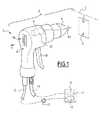
図1及び図2では、コーティング用製品を適用するための手動ガン2の第1実施形態が図示される。例においては、コーティング用製品は紛体形態の塗料である。 1 and 2 illustrate a first embodiment of a manual gun 2 for applying a coating product. In the example, the coating product is a powder paint.
ガン2は、ガンにコーティング用製品を供給するためのポンプ11と、ポンプを制御するための制御モジュール13と、ガン2に電力を供給するための電気モジュール15とを含む、適用ステーションSに属する。電気モジュール及び制御モジュールは、同一の電空モジュール17内でグループ分けされる。管12はガン2をポンプ11と接続する。低電圧ケーブル14は、ガン2を電気モジュール15と接続する。 The gun 2 belongs to the application station S, which includes a
ガン2は、本体4と、コンベヤーCによって動かされるコーティングされるべき対象物Oに向けてコーティング用製品を吐出するためのノズル6とを含む。有利には、ノズル6は、本体4上で取り外し可能に設置される。ガン2は扁平ジェットを持つノズルと、円形ジェットを持つノズルとの両方で動作することができる。 The gun 2 includes a
高電圧ユニット42は本体4の中に位置し、ケーブル14を通じて電力が供給された場合は、予め調整された電圧/電流特性に従ってコーティング用製品を静電的に帯電するために設計される。有利には、高電圧ユニットは、ノズル6の中心に位置した電極62を含む。 The
ガン2はまた、例において本体4に対して可動なトリガーである制御部材10を含む。制御部材10は、ガン2によるコーティング用製品の適用を妨げ、高電圧ユニットに電力が供給されない非アクティブ停止構成と、コーティング用製品の適用を妨げず、高電圧ユニットに電力が供給されるアクティブ動作構成との間で、ペインタによって操作可能である。したがって、部材10は、コーティング用製品を適用し、コーティング用製品を高電圧に帯電するための制御手段を形成する。典型的に、制御部材10は、ユーザーによって、ガン2の本体4の後面8に対してユーザーの手のひらを置き、ユーザーの指で制御トリガー10を引くことによって、動作することができる。代替的に、制御トリガーは、プッシュボタンとして提供されることがあり、次いで、ユーザーはユーザーの人差し指でボタンを押す。 The gun 2 also includes a
例において、制御部材10は、コーティング用製品の供給を遮断するために作用し、高電圧ユニットに電力を供給することを選択的に遮断するための電気接触器又はスイッチ(図示なし)に作用する。 In an example, the
図中に確認できない復帰手段は、制御部材10を非アクティブ構成に復帰することができる。 The return means that cannot be confirmed in the figure can return the
ユーザーインターフェイス16は、コーティング用製品の吐出ノズル6と反対側の本体4の面に相当するガン2の本体4の後面8上に位置する。ユーザーインターフェイス16が本体4の後面8上に位置することにより、ユーザーによるその取扱いが容易になる。 The
インターフェイス16は、制御部材10がアクティブ構成にある場合はコーティング用製品の流量を手動で調整することができ、部材10が非アクティブ構成にある場合は電圧/電流特性を手動で選択することができる、2つの制御ボタン、18a及び18bをそれぞれ含む。したがって、制御ボタン18a及び18bは、複数の高電圧レベルの中から、製品が静電的に帯電される電圧/電流特性を選択するために調整手段と、またコーティング用製品の流量を調整するための手段とを形成する。 The
特に、両ボタン18a及び18bは、制御部材10がアクティブ構成にある場合はコーティング用製品の流量にのみ作用することができ、部材10が非アクティブ構成にある場合は電圧/電流特性にのみ作用することができる。したがって、例えば、独国特許出願公開第102005017931号明細書で説明されたガンの実施形態とは異なり、本発明においては、制御部材10がアクティブ構成にある場合は、ユーザーは電圧/電流特性を修正することができなく、制御部材10が非アクティブ構成にある場合は、ユーザーは噴射流量を調整することができない。 In particular, both
ジェットの性質は、使用される電圧/電流特性に従って変わる。例えば、小さい傾きを持つ電圧/電流特性は、扁平ジェットを持つノズルに対してさらに適応し、より大きい傾きを持つ電圧/電流特性は、それに関しては、円形ジェットを持つノズルに対してむしろ適応する。また、電圧/電流特性はまた、コーティングされるべき部品の複雑さに従って適応する。 The nature of the jet depends on the voltage / current characteristics used. For example, a voltage / current characteristic with a small slope is more adapted to a nozzle with a flat jet, and a voltage / current characteristic with a larger slope is rather adapted to a nozzle with a circular jet in that regard. .. Also, the voltage / current characteristics are adapted according to the complexity of the part to be coated.
第1ボタン18aは、部材10がアクティブ構成にある場合はコーティング用製品の流量を増加することができ、部材10が非アクティブ構成にある場合は電圧/電流特性を変えることができる。第2ボタン18bは、部材が非アクティブ構成にある場合はコーティング用製品の流量を減らすことができ、部材が非アクティブ構成にある場合は電圧/電流特性を変えることができる。 The
特に、第1ボタン18aは、部材10が非アクティブ構成にある場合はより小さい傾きを持つ電圧/電流特性を選択することができ、第2ボタン18bは、部材10が非アクティブ構成にある場合はより大きい傾きを持つ電圧/電流特性を選択することができる。 In particular, the
第1ボタン18aは、符号「+」でコーティングされ、第2ボタン18bは符号「−」でコーティングされ、それにより、それらの使用が直感的になる。ガン2が鉛直に保持された場合は、ボタン18bはボタン18aの上に配置される。 The
制御インターフェイス16はまた、異なる予め調整された電圧/電流特性の中から選択された電圧/電流特性を示すための、2つの表示灯20a及び20bをそれぞれ含む。図1及び図2の例において、それぞれが特定の電圧/電流特性に相当する、2つの高電圧レベル、HV1及びHV2のそれぞれが利用可能である。これらの特性の両方は、電気モジュール15上で予め調整される。したがって、ボタン18a及び18bの起動は、部材10が非アクティブ構成にある場合は、高電圧レベルHV1及びHV2に相当する特性の中から、ユニット42によって電極6に適用される電圧/電流特性を選択することができる。高電圧HV1に相当する電圧/電流特性が使用された場合は、表示灯20aが点灯し、高電圧HV2に相当する電圧/電流特性が使用された場合は、表示灯20bが点灯する。表示灯20a及び20bは発光ダイオードである。 The
有利には、表示灯20a又は20bは、制御部材10の構成に関係なく、点灯したままである。 Advantageously, the indicator lights 20a or 20b remain lit regardless of the configuration of the
任意選択で、電空モジュールはまた、制御インターフェイスを含む。 Optionally, the electropneumatic module also includes a control interface.
図3では、本発明に係るガンの第2実施形態に属するユーザーインターフェイスを図示する。図4では、本発明に係るガンの第3実施形態に属するユーザーインターフェイスを図示する。以下においては、簡潔にするために、第1実施形態に対する相違点のみを説明する。さらに、第1実施形態と同一の部材は、それらの参照番号を維持し、その他の部材は他の参照番号を有する。 FIG. 3 illustrates a user interface belonging to the second embodiment of the gun according to the present invention. FIG. 4 illustrates a user interface belonging to the third embodiment of the cancer according to the present invention. In the following, for the sake of brevity, only the differences from the first embodiment will be described. Further, the same members as in the first embodiment maintain their reference numbers, and the other members have other reference numbers.
図3の実施形態において、ユーザーは、3つの利用可能な特性の中から電圧/電流特性を選択することができる。次いで、図3のユーザーインターフェイス16は、選択された電圧/電流特性を示すために、3つの表示灯20a、20b及び20cをそれぞれ含む。 In the embodiment of FIG. 3, the user can select the voltage / current characteristic from among the three available characteristics. The
最初の2つ実施形態とは異なり、図4の実施形態においては、ユーザーインターフェイス16は水平に位置する。したがって、ガン2が上下に保持された場合は、ボタン18bはボタン18aの左側に配置される。 Unlike the first two embodiments, in the embodiment of FIG. 4, the
コーティング用製品の適用を進めるために、ユーザーは、工程a)の間に、ガンを握ることによって始め、次いで、工程b)の間に、ユーザーは制御ボタン18a及び18bに作用することによって高電圧ユニット42の電圧/電流特性を選択する。次に、ユーザーは、工程c)の間に、非アクティブ構成からアクティブ構成に制御部材10を操作し、したがって噴射を始める。最後に、制御ボタン18a及び18bに作用することによって、ユーザーは、工程d)の間に、ガン2によって適用されるコーティング用製品の流量を調整する。 To advance the application of coating products, the user begins by grasping the gun during step a) and then during step b) the user high voltage by acting on the
有利には、ガン2が、制御部材10を非アクティブ構成に復帰するための手段を含むと仮定すると、制御部材10が非アクティブ構成に復帰した場合は、制御ボタン18a及び18bに作用することによって、新規の電圧/電流特性を選択することができる。 Advantageously, assuming that the gun 2 includes means for returning the
図示されていない代替形態において、ペインタによって選択することができる電圧/電流特性の数は4つ以上である。 In alternative embodiments not shown, the number of voltage / current characteristics that can be selected by the painter is four or more.
図示されていない代替形態において、ガンは、異なる予め調整された電圧/電流特性の中から選択された電圧/電流特性をペインタに示すための単一の表示灯を含む。有利には、表示灯は発光ダイオードであり、色が、選択された電圧/電流特性に依存して変わる。代替的に、表示灯は、点滅発光ダイオードであり、その点滅頻度は、選択された電圧/電流特性に従って変わる。 In an alternative form not shown, the gun comprises a single indicator light to indicate to the painter a voltage / current characteristic selected from different pre-tuned voltage / current characteristics. Advantageously, the indicator light is a light emitting diode and the color changes depending on the selected voltage / current characteristics. Alternatively, the indicator light is a blinking light emitting diode whose blinking frequency varies according to the selected voltage / current characteristics.
図示されていない別の実施形態によれば、ガン2は、コーティング用製品の流量の変化を示すための別の表示灯を含む。有利には、ガンは、コーティング用製品の最大流量又は最小流量が得られた場合を示すための別の表示灯をさらに含む。この表示灯は、前で説明されたタイプであることができ、コーティング用製品の流量の変化を示すために使用されたものと同一の表示灯であることができる。 According to another embodiment (not shown), the gun 2 includes another indicator light for indicating a change in the flow rate of the coating product. Advantageously, the gun further includes another indicator light to indicate when the maximum or minimum flow rate of the coating product has been obtained. This indicator light can be of the type described above and can be the same indicator light used to indicate changes in the flow rate of the coating product.
図示されていない別の実施形態によれば、ユーザーインターフェイスは、選択された電圧/電流特性を代表する棒グラフ、及び/又はコーティング用製品の流量を代表する棒グラフを含む。各棒グラフは、選択された電圧/電流特性又はコーティング用製品の流量を常に表示するために構成される。 According to another embodiment not shown, the user interface includes a bar graph representing selected voltage / current characteristics and / or a bar graph representing the flow rate of the coating product. Each bar graph is configured to constantly display the selected voltage / current characteristics or flow rate of the coating product.
有利には、同一の棒グラフを、選択された電圧/電流特性及びコーティング用製品の流量を代替的に示すために使用することができる。例において、この棒グラフは、制御部材が非アクティブ構成にある場合は選択された電圧/電流特性を、又は、制御部材がアクティブ構成にある場合はコーティング用製品の流量を表示するために構成される。 Advantageously, the same bar graph can be used as an alternative to show the selected voltage / current characteristics and flow rate of the coating product. In an example, this bar graph is configured to display the selected voltage / current characteristics if the control member is in an inactive configuration, or to display the flow rate of the coating product if the control member is in an active configuration. ..
例えば、棒グラフを、ボタン18a及び18bを押すことによって、オペレータにこれが高電圧であるか又は流量であるかを示すために、制御部材10の位置に従って色を変えるために構成することができる。 For example, a bar graph can be configured to change color according to the position of the
上で考慮された代替形態及び実施形態の特性は、本発明の新規の実施形態を作り出すために、一緒に組み合わせることができる。 The alternative embodiments and characteristics of the embodiments discussed above can be combined together to create a novel embodiment of the invention.
Claims (13)
Translated fromJapanese−複数の予め調整された電圧/電流特性の中から、コーティング用製品が静電的に帯電される電圧/電流特性を選択するための調整手段(18a、18b)と、
−コーティング用製品の適用を妨げ、前記高電圧ユニットに電力が供給されない非アクティブ構成と、コーティング用製品の適用を妨げず、前記高電圧ユニットに電力が供給されるアクティブ構成との間で操作可能である、制御部材(10)と
を含む、コーティング用製品を適用するための手動ガン(2)であって、
前記調整手段が、前記制御部材(10)がアクティブ構成にある場合は、前記手動ガンによって適用されるコーティング用製品の流量にのみ作用することができ、前記制御部材が非アクティブ構成にある場合は、前記高電圧ユニット(42)の電圧/電流特性(HV1、HV2、HVn)にのみ作用することができる、制御ボタン(18a、18b)を含むことを特徴とする、手動ガン(2)。-A high voltage unit (42) designed to electrostatically charge the coating product according to pre-tuned voltage / current characteristics (HV1, HV2, HVn) when powered.
-Adjusting means (18a, 18b) for selecting the voltage / current characteristic at which the coating product is electrostatically charged from among a plurality of pre-adjusted voltage / current characteristics.
-Operatable between an inactive configuration that interferes with the application of the coating product and does not power the high voltage unit and an active configuration that does not interfere with the application of the coating product and powers the high voltage unit. A manual gun (2) for applying a coating product, including a control member (10).
The adjusting means can act only on the flow rate of the coating product applied by the manual gun when the control member (10) is in the active configuration, and when the control member is in the inactive configuration. A manual gun (2) comprising control buttons (18a, 18b) that canonly act on the voltage / current characteristics (HV1, HV2, HVn) of the high voltage unit (42).
−前記制御部材(10)がアクティブ構成にある場合はコーティング用製品の流量を増やし、前記制御部材が非アクティブ構成にある場合は電圧/電流特性を変えるための、第1ボタン(18a)と、
−前記制御部材がアクティブ構成にある場合はコーティング用製品の流量を減らし、前記制御部材が非アクティブ構成にある場合は電圧/電流特性を変えるための、第2ボタン(18b)と
を含むことを特徴とする、請求項1に記載の手動ガン。The control button
-A first button (18a) for increasing the flow rate of the coating product when the control member (10) is in the active configuration and changing the voltage / current characteristics when the control member (10) is in the inactive configuration.
-Includes a second button (18b) to reduce the flow rate of the coating product when the control member is in the active configuration and to change the voltage / current characteristics when the control member is in the inactive configuration. The manual gun according to claim 1, wherein the manual gun is characterized.
−前記手動ガン(2)にコーティング用製品を供給するためのポンプ(11)と、
−前記ポンプを制御するための制御モジュール(13)と、
−前記手動ガン(2)に電力を供給するための電気モジュール(15)と
を含む、コーティング用製品を適用するためのステーション(S)であって、
前記手動ガン(2)が、請求項1〜11のいずれか1項に記載のものであることを特徴とする、ステーション(S)。-Manual gun (2) and
-A pump (11) for supplying a coating product to the manual gun (2), and
-A control module (13) for controlling the pump and
-A station (S) for applying a coating product, including an electrical module (15) for supplying power to the manual gun (2).
The station (S), wherein the manual gun (2) isthe one according to any one of claims 1 to 11.
a)前記手動ガンを握る工程と、
b)前記制御ボタン(18a、18b)に作用することによって、前記高電圧ユニット(42)の電圧/電流特性(HV1、HV2、HVn)を選択する工程と、
c)非アクティブ構成からアクティブ構成に前記制御部材(10)を操作する工程と、
d)前記制御ボタン(18a、18b)に作用することによって、前記手動ガンによって適用されるコーティング用製品の流量を調整する工程と
からなる一連の工程を含む、方法。A method for applying a coating product with the manual gun according to any one of claims 1 to11.
a) The process of gripping the manual gun and
b) A step of selecting the voltage / current characteristics (HV1, HV2, HVn) of the high voltage unit (42) by acting on the control buttons (18a, 18b).
c) The step of operating the control member (10) from the inactive configuration to the active configuration, and
d) A method comprising a series of steps comprising adjusting the flow rate of a coating product applied by the manual gun by acting on the control buttons (18a, 18b).
Applications Claiming Priority (2)
| Application Number | Priority Date | Filing Date | Title |
|---|---|---|---|
| FR1652397 | 2016-03-21 | ||
| FR1652397AFR3048894B1 (en) | 2016-03-21 | 2016-03-21 | MANUAL FOR APPLYING A COATING PRODUCT AND STATION FOR APPLYING A COATING PRODUCT COMPRISING SUCH A PISTOL |
Publications (2)
| Publication Number | Publication Date |
|---|---|
| JP2017170432A JP2017170432A (en) | 2017-09-28 |
| JP6912226B2true JP6912226B2 (en) | 2021-08-04 |
Family
ID=56069110
Family Applications (1)
| Application Number | Title | Priority Date | Filing Date |
|---|---|---|---|
| JP2017043623AActiveJP6912226B2 (en) | 2016-03-21 | 2017-03-08 | Manual coating guns and coating stations containing such guns |
Country Status (14)
| Country | Link |
|---|---|
| US (1) | US20170266681A1 (en) |
| EP (1) | EP3222359B1 (en) |
| JP (1) | JP6912226B2 (en) |
| KR (1) | KR102329795B1 (en) |
| CN (1) | CN107214055A (en) |
| BR (1) | BR102017004747A2 (en) |
| DK (1) | DK3222359T3 (en) |
| ES (1) | ES2770085T3 (en) |
| FR (1) | FR3048894B1 (en) |
| HR (1) | HRP20200030T1 (en) |
| HU (1) | HUE047304T2 (en) |
| PL (1) | PL3222359T3 (en) |
| PT (1) | PT3222359T (en) |
| RU (1) | RU2017109118A (en) |
Families Citing this family (3)
| Publication number | Priority date | Publication date | Assignee | Title |
|---|---|---|---|---|
| CN109813977A (en)* | 2017-11-20 | 2019-05-28 | 上海普锐马电子有限公司 | An electrostatic gun with a touch screen |
| CN110918281A (en)* | 2018-09-03 | 2020-03-27 | 七星瓢虫环境科技(苏州)有限公司 | Electrostatic paint spray gun and method of use |
| KR102251235B1 (en) | 2019-11-12 | 2021-05-13 | 한국해양과학기술원 | Gun type underwater coating equipment using a piston |
Family Cites Families (12)
| Publication number | Priority date | Publication date | Assignee | Title |
|---|---|---|---|---|
| CH620600A5 (en)* | 1977-05-12 | 1980-12-15 | Alex Hengartner | |
| DE19838275A1 (en)* | 1998-08-22 | 2000-02-24 | Itw Gema Ag | Manual spray coating pistol has manually displaceable control element on pistol exterior for setting parameter(s) of operating media, including coating material, electrode electrical energy |
| FR2809334B1 (en)* | 2000-05-29 | 2003-02-28 | Eisenmann Sarl | SPRAYING DEVICE FOR SPRAYING A COATING PRODUCT |
| DE10232869A1 (en)* | 2002-07-19 | 2004-01-29 | Manfred Zorn | Powder spray pistol has double or multiple trigger on pistol grip attached to control circuit and powder supply system to give thin or thick cloud of powder |
| DE102005017931A1 (en) | 2005-04-18 | 2006-10-19 | Itw Gema Ag | Powder spray coating gun and gun body for this purpose |
| US7460924B2 (en)* | 2005-06-16 | 2008-12-02 | Illinois Tool Works Inc. | In-gun power supply control |
| US8037844B2 (en)* | 2007-10-31 | 2011-10-18 | Nordson Corporation | Spray gun having display and control members on gun |
| EP2055391B2 (en)* | 2007-10-31 | 2022-02-09 | Nordson Corporation | Improved spray gun trigger apparatus and methods |
| JP5967647B2 (en)* | 2012-07-13 | 2016-08-10 | アネスト岩田株式会社 | Electrostatic coating air spray gun, electrostatic coating system and electrostatic coating method |
| BR112015006649A2 (en)* | 2012-10-01 | 2017-07-04 | Graco Minnesota Inc | electrostatic spray gun |
| CN205109915U (en)* | 2015-11-02 | 2016-03-30 | 安徽理工大学 | Dual power supply's automatic paint spraying apparatus of electrostatic spinning |
| US10773266B2 (en)* | 2015-12-01 | 2020-09-15 | Carlisle Fluid Technologies, Inc. | Spray tool power supply system and method |
- 2016
- 2016-03-21FRFR1652397Apatent/FR3048894B1/enactiveActive
- 2017
- 2017-03-08JPJP2017043623Apatent/JP6912226B2/enactiveActive
- 2017-03-09BRBR102017004747-4Apatent/BR102017004747A2/ennot_activeApplication Discontinuation
- 2017-03-13USUS15/456,813patent/US20170266681A1/ennot_activeAbandoned
- 2017-03-16KRKR1020170033257Apatent/KR102329795B1/enactiveActive
- 2017-03-20RURU2017109118Apatent/RU2017109118A/ennot_activeApplication Discontinuation
- 2017-03-20DKDK17161775.6Tpatent/DK3222359T3/enactive
- 2017-03-20ESES17161775Tpatent/ES2770085T3/enactiveActive
- 2017-03-20PTPT171617756Tpatent/PT3222359T/enunknown
- 2017-03-20EPEP17161775.6Apatent/EP3222359B1/enactiveActive
- 2017-03-20HUHUE17161775Apatent/HUE047304T2/enunknown
- 2017-03-20CNCN201710166252.5Apatent/CN107214055A/enactivePending
- 2017-03-20PLPL17161775Tpatent/PL3222359T3/enunknown
- 2020
- 2020-01-09HRHRP20200030TTpatent/HRP20200030T1/enunknown
Also Published As
| Publication number | Publication date |
|---|---|
| JP2017170432A (en) | 2017-09-28 |
| FR3048894A1 (en) | 2017-09-22 |
| DK3222359T3 (en) | 2020-03-16 |
| FR3048894B1 (en) | 2018-04-20 |
| RU2017109118A (en) | 2018-09-20 |
| PT3222359T (en) | 2020-03-04 |
| EP3222359A1 (en) | 2017-09-27 |
| HUE047304T2 (en) | 2020-04-28 |
| US20170266681A1 (en) | 2017-09-21 |
| HRP20200030T1 (en) | 2020-03-20 |
| RU2017109118A3 (en) | 2020-07-02 |
| KR20170110513A (en) | 2017-10-11 |
| PL3222359T3 (en) | 2020-07-13 |
| ES2770085T3 (en) | 2020-06-30 |
| EP3222359B1 (en) | 2019-12-25 |
| KR102329795B1 (en) | 2021-11-22 |
| CN107214055A (en) | 2017-09-29 |
| BR102017004747A2 (en) | 2017-09-26 |
Similar Documents
| Publication | Publication Date | Title |
|---|---|---|
| JP5714795B2 (en) | Coating material spray gun | |
| JP6912226B2 (en) | Manual coating guns and coating stations containing such guns | |
| US11623231B2 (en) | Electrostatic fluid delivery system | |
| JP7271772B2 (en) | Spray gun, lighting assembly and method of operating the spray gun | |
| US9550250B2 (en) | Torch-mounted fingertip welding controller | |
| MX2014012419A (en) | Air flow switch for an electrostatic tool. | |
| CA2341254C (en) | Manual spray coating gun | |
| EP2055391B2 (en) | Improved spray gun trigger apparatus and methods | |
| EP3305157A1 (en) | Vacuum | |
| JP6148567B2 (en) | Electrostatic coating equipment | |
| EP3126056B1 (en) | Electrostatic spray gun having external charge points | |
| CN107930877A (en) | A kind of electrostatic powder coating machine sprayed automatically | |
| JP3196758U (en) | Portable painting equipment | |
| JP6803605B2 (en) | Painting control device and painting device | |
| WO2022229640A1 (en) | Improvements to spray apparatus | |
| JP2022108427A (en) | electrostatic painting gun | |
| JPS634519Y2 (en) | ||
| CN202591032U (en) | Dual-purpose controlling handle for sprayer to spray water and control power source | |
| JP2015166074A (en) | Electrostatic coating equipment | |
| JP2004122016A (en) | Gun for powder electrostatic coating |
Legal Events
| Date | Code | Title | Description |
|---|---|---|---|
| A621 | Written request for application examination | Free format text:JAPANESE INTERMEDIATE CODE: A621 Effective date:20200207 | |
| A977 | Report on retrieval | Free format text:JAPANESE INTERMEDIATE CODE: A971007 Effective date:20210127 | |
| A131 | Notification of reasons for refusal | Free format text:JAPANESE INTERMEDIATE CODE: A131 Effective date:20210209 | |
| A521 | Request for written amendment filed | Free format text:JAPANESE INTERMEDIATE CODE: A523 Effective date:20210510 | |
| TRDD | Decision of grant or rejection written | ||
| A01 | Written decision to grant a patent or to grant a registration (utility model) | Free format text:JAPANESE INTERMEDIATE CODE: A01 Effective date:20210608 | |
| A61 | First payment of annual fees (during grant procedure) | Free format text:JAPANESE INTERMEDIATE CODE: A61 Effective date:20210708 | |
| R150 | Certificate of patent or registration of utility model | Ref document number:6912226 Country of ref document:JP Free format text:JAPANESE INTERMEDIATE CODE: R150 | |
| R250 | Receipt of annual fees | Free format text:JAPANESE INTERMEDIATE CODE: R250 | |
| R250 | Receipt of annual fees | Free format text:JAPANESE INTERMEDIATE CODE: R250 |