JP6911065B2 - Position light integrated winker device - Google Patents
Position light integrated winker deviceDownload PDFInfo
- Publication number
- JP6911065B2 JP6911065B2JP2019009770AJP2019009770AJP6911065B2JP 6911065 B2JP6911065 B2JP 6911065B2JP 2019009770 AJP2019009770 AJP 2019009770AJP 2019009770 AJP2019009770 AJP 2019009770AJP 6911065 B2JP6911065 B2JP 6911065B2
- Authority
- JP
- Japan
- Prior art keywords
- light
- winker
- light source
- guide member
- source
- Prior art date
- Legal status (The legal status is an assumption and is not a legal conclusion. Google has not performed a legal analysis and makes no representation as to the accuracy of the status listed.)
- Expired - Fee Related
Links
Images


Classifications
- B—PERFORMING OPERATIONS; TRANSPORTING
- B62—LAND VEHICLES FOR TRAVELLING OTHERWISE THAN ON RAILS
- B62J—CYCLE SADDLES OR SEATS; AUXILIARY DEVICES OR ACCESSORIES SPECIALLY ADAPTED TO CYCLES AND NOT OTHERWISE PROVIDED FOR, e.g. ARTICLE CARRIERS OR CYCLE PROTECTORS
- B62J6/00—Arrangement of optical signalling or lighting devices on cycles; Mounting or supporting thereof; Circuits therefor
- B62J6/05—Direction indicators
- B62J6/055—Electrical means, e.g. lamps
- B—PERFORMING OPERATIONS; TRANSPORTING
- B60—VEHICLES IN GENERAL
- B60Q—ARRANGEMENT OF SIGNALLING OR LIGHTING DEVICES, THE MOUNTING OR SUPPORTING THEREOF OR CIRCUITS THEREFOR, FOR VEHICLES IN GENERAL
- B60Q1/00—Arrangement of optical signalling or lighting devices, the mounting or supporting thereof or circuits therefor
- B60Q1/0029—Spatial arrangement
- B60Q1/0035—Spatial arrangement relative to the vehicle
- B—PERFORMING OPERATIONS; TRANSPORTING
- B60—VEHICLES IN GENERAL
- B60Q—ARRANGEMENT OF SIGNALLING OR LIGHTING DEVICES, THE MOUNTING OR SUPPORTING THEREOF OR CIRCUITS THEREFOR, FOR VEHICLES IN GENERAL
- B60Q1/00—Arrangement of optical signalling or lighting devices, the mounting or supporting thereof or circuits therefor
- B60Q1/0029—Spatial arrangement
- B60Q1/0041—Spatial arrangement of several lamps in relation to each other
- B60Q1/0052—Spatial arrangement of several lamps in relation to each other concentric
- B—PERFORMING OPERATIONS; TRANSPORTING
- B60—VEHICLES IN GENERAL
- B60Q—ARRANGEMENT OF SIGNALLING OR LIGHTING DEVICES, THE MOUNTING OR SUPPORTING THEREOF OR CIRCUITS THEREFOR, FOR VEHICLES IN GENERAL
- B60Q1/00—Arrangement of optical signalling or lighting devices, the mounting or supporting thereof or circuits therefor
- B60Q1/26—Arrangement of optical signalling or lighting devices, the mounting or supporting thereof or circuits therefor the devices being primarily intended to indicate the vehicle, or parts thereof, or to give signals, to other traffic
- B60Q1/2607—Arrangement of optical signalling or lighting devices, the mounting or supporting thereof or circuits therefor the devices being primarily intended to indicate the vehicle, or parts thereof, or to give signals, to other traffic comprising at least two indicating lamps
- F—MECHANICAL ENGINEERING; LIGHTING; HEATING; WEAPONS; BLASTING
- F21—LIGHTING
- F21S—NON-PORTABLE LIGHTING DEVICES; SYSTEMS THEREOF; VEHICLE LIGHTING DEVICES SPECIALLY ADAPTED FOR VEHICLE EXTERIORS
- F21S43/00—Signalling devices specially adapted for vehicle exteriors, e.g. brake lamps, direction indicator lights or reversing lights
- F21S43/10—Signalling devices specially adapted for vehicle exteriors, e.g. brake lamps, direction indicator lights or reversing lights characterised by the light source
- F21S43/13—Signalling devices specially adapted for vehicle exteriors, e.g. brake lamps, direction indicator lights or reversing lights characterised by the light source characterised by the type of light source
- F21S43/14—Light emitting diodes [LED]
- F—MECHANICAL ENGINEERING; LIGHTING; HEATING; WEAPONS; BLASTING
- F21—LIGHTING
- F21S—NON-PORTABLE LIGHTING DEVICES; SYSTEMS THEREOF; VEHICLE LIGHTING DEVICES SPECIALLY ADAPTED FOR VEHICLE EXTERIORS
- F21S43/00—Signalling devices specially adapted for vehicle exteriors, e.g. brake lamps, direction indicator lights or reversing lights
- F21S43/10—Signalling devices specially adapted for vehicle exteriors, e.g. brake lamps, direction indicator lights or reversing lights characterised by the light source
- F21S43/19—Attachment of light sources or lamp holders
- F—MECHANICAL ENGINEERING; LIGHTING; HEATING; WEAPONS; BLASTING
- F21—LIGHTING
- F21S—NON-PORTABLE LIGHTING DEVICES; SYSTEMS THEREOF; VEHICLE LIGHTING DEVICES SPECIALLY ADAPTED FOR VEHICLE EXTERIORS
- F21S43/00—Signalling devices specially adapted for vehicle exteriors, e.g. brake lamps, direction indicator lights or reversing lights
- F21S43/20—Signalling devices specially adapted for vehicle exteriors, e.g. brake lamps, direction indicator lights or reversing lights characterised by refractors, transparent cover plates, light guides or filters
- F21S43/235—Light guides
- F21S43/236—Light guides characterised by the shape of the light guide
- F21S43/237—Light guides characterised by the shape of the light guide rod-shaped
- F—MECHANICAL ENGINEERING; LIGHTING; HEATING; WEAPONS; BLASTING
- F21—LIGHTING
- F21S—NON-PORTABLE LIGHTING DEVICES; SYSTEMS THEREOF; VEHICLE LIGHTING DEVICES SPECIALLY ADAPTED FOR VEHICLE EXTERIORS
- F21S43/00—Signalling devices specially adapted for vehicle exteriors, e.g. brake lamps, direction indicator lights or reversing lights
- F21S43/20—Signalling devices specially adapted for vehicle exteriors, e.g. brake lamps, direction indicator lights or reversing lights characterised by refractors, transparent cover plates, light guides or filters
- F21S43/235—Light guides
- F21S43/236—Light guides characterised by the shape of the light guide
- F21S43/239—Light guides characterised by the shape of the light guide plate-shaped
- F—MECHANICAL ENGINEERING; LIGHTING; HEATING; WEAPONS; BLASTING
- F21—LIGHTING
- F21S—NON-PORTABLE LIGHTING DEVICES; SYSTEMS THEREOF; VEHICLE LIGHTING DEVICES SPECIALLY ADAPTED FOR VEHICLE EXTERIORS
- F21S43/00—Signalling devices specially adapted for vehicle exteriors, e.g. brake lamps, direction indicator lights or reversing lights
- F21S43/20—Signalling devices specially adapted for vehicle exteriors, e.g. brake lamps, direction indicator lights or reversing lights characterised by refractors, transparent cover plates, light guides or filters
- F21S43/235—Light guides
- F21S43/236—Light guides characterised by the shape of the light guide
- F21S43/241—Light guides characterised by the shape of the light guide of complex shape
- F—MECHANICAL ENGINEERING; LIGHTING; HEATING; WEAPONS; BLASTING
- F21—LIGHTING
- F21S—NON-PORTABLE LIGHTING DEVICES; SYSTEMS THEREOF; VEHICLE LIGHTING DEVICES SPECIALLY ADAPTED FOR VEHICLE EXTERIORS
- F21S43/00—Signalling devices specially adapted for vehicle exteriors, e.g. brake lamps, direction indicator lights or reversing lights
- F21S43/20—Signalling devices specially adapted for vehicle exteriors, e.g. brake lamps, direction indicator lights or reversing lights characterised by refractors, transparent cover plates, light guides or filters
- F21S43/235—Light guides
- F21S43/242—Light guides characterised by the emission area
- F21S43/245—Light guides characterised by the emission area emitting light from one or more of its major surfaces
- F—MECHANICAL ENGINEERING; LIGHTING; HEATING; WEAPONS; BLASTING
- F21—LIGHTING
- F21S—NON-PORTABLE LIGHTING DEVICES; SYSTEMS THEREOF; VEHICLE LIGHTING DEVICES SPECIALLY ADAPTED FOR VEHICLE EXTERIORS
- F21S43/00—Signalling devices specially adapted for vehicle exteriors, e.g. brake lamps, direction indicator lights or reversing lights
- F21S43/20—Signalling devices specially adapted for vehicle exteriors, e.g. brake lamps, direction indicator lights or reversing lights characterised by refractors, transparent cover plates, light guides or filters
- F21S43/235—Light guides
- F21S43/249—Light guides with two or more light sources being coupled into the light guide
- F—MECHANICAL ENGINEERING; LIGHTING; HEATING; WEAPONS; BLASTING
- F21—LIGHTING
- F21S—NON-PORTABLE LIGHTING DEVICES; SYSTEMS THEREOF; VEHICLE LIGHTING DEVICES SPECIALLY ADAPTED FOR VEHICLE EXTERIORS
- F21S43/00—Signalling devices specially adapted for vehicle exteriors, e.g. brake lamps, direction indicator lights or reversing lights
- F21S43/20—Signalling devices specially adapted for vehicle exteriors, e.g. brake lamps, direction indicator lights or reversing lights characterised by refractors, transparent cover plates, light guides or filters
- F21S43/26—Refractors, transparent cover plates, light guides or filters not provided in groups F21S43/235 - F21S43/255
- F—MECHANICAL ENGINEERING; LIGHTING; HEATING; WEAPONS; BLASTING
- F21—LIGHTING
- F21W—INDEXING SCHEME ASSOCIATED WITH SUBCLASSES F21K, F21L, F21S and F21V, RELATING TO USES OR APPLICATIONS OF LIGHTING DEVICES OR SYSTEMS
- F21W2103/00—Exterior vehicle lighting devices for signalling purposes
- F21W2103/10—Position lights
- F—MECHANICAL ENGINEERING; LIGHTING; HEATING; WEAPONS; BLASTING
- F21—LIGHTING
- F21W—INDEXING SCHEME ASSOCIATED WITH SUBCLASSES F21K, F21L, F21S and F21V, RELATING TO USES OR APPLICATIONS OF LIGHTING DEVICES OR SYSTEMS
- F21W2103/00—Exterior vehicle lighting devices for signalling purposes
- F21W2103/20—Direction indicator lights
- F—MECHANICAL ENGINEERING; LIGHTING; HEATING; WEAPONS; BLASTING
- F21—LIGHTING
- F21W—INDEXING SCHEME ASSOCIATED WITH SUBCLASSES F21K, F21L, F21S and F21V, RELATING TO USES OR APPLICATIONS OF LIGHTING DEVICES OR SYSTEMS
- F21W2107/00—Use or application of lighting devices on or in particular types of vehicles
- F21W2107/10—Use or application of lighting devices on or in particular types of vehicles for land vehicles
- F21W2107/13—Use or application of lighting devices on or in particular types of vehicles for land vehicles for cycles
- F21W2107/17—Use or application of lighting devices on or in particular types of vehicles for land vehicles for cycles for motorcycles
Landscapes
- Engineering & Computer Science (AREA)
- General Engineering & Computer Science (AREA)
- Mechanical Engineering (AREA)
- Physics & Mathematics (AREA)
- Microelectronics & Electronic Packaging (AREA)
- Optics & Photonics (AREA)
- Non-Portable Lighting Devices Or Systems Thereof (AREA)
- Lighting Device Outwards From Vehicle And Optical Signal (AREA)
Description
Translated fromJapanese本発明は、視認性が改良された鞍乗型車両のポジションライト一体型ウィンカ装置に関する。 The present invention relates to a position light integrated winker device for a saddle-mounted vehicle with improved visibility.
ポジションライトとウィンカライトとを一体に備えるポジションライト一体型ウィンカ装置の従来技術として、特許文献1のものがある。 Patent Document 1 is a conventional technique of a position light integrated winker device including a position light and a winker light integrally.
しかしながら、この従来技術のポジションライト一体型ウィンカ装置は、ポジションライトによる発光領域をバルブ(電球)タイプの点光源によって形成していたので、光源として例えばLED(発光ダイオード)を用いる場合には、その指向性が高いために、発光面積を大きく見せることが課題となるものであった。すなわち、この従来技術のポジションライト一体型ウィンカ装置は、視認性にさらなる改良の余地を有していた。 However, in this prior art position light integrated winker device, the light emitting region of the position light is formed by a valve (bulb) type point light source. Therefore, when an LED (light emitting diode) is used as the light source, for example, the light emitting region is formed. Since the directivity is high, it has been a problem to make the light emitting area look large. That is, this prior art position light integrated winker device has room for further improvement in visibility.
この従来技術の課題に鑑み、本発明は、視認性が改良された鞍乗型車両のポジションライト一体型ウィンカ装置を提供することを目的とする。 In view of the problems of the prior art, it is an object of the present invention to provide a position light integrated winker device for a saddle-mounted vehicle with improved visibility.
上記目的を達成するため、本発明は、
共通のハウジング(40)にウィンカライト光源(90)とポジションライト光源(91,92)とが収容される、鞍乗型車両のポジションライト一体型ウィンカ装置(7)において、
前記ポジションライト光源(91,92)の発光で形成されるポジションライト発光領域(87)が前記ウィンカライト光源(90)の発光で形成されるウィンカライト発光領域(86)を囲むこと
を第1の特徴とする。In order to achieve the above object, the present invention
In the position light integrated winker device (7) of a saddle-type vehicle in which a winker light light source (90) and a position light light source (91, 92) are housed in a common housing (40).
First, the position light light emitting region (87) formed by the light emission of the position light light source (91, 92) surrounds the winker light light emitting region (86) formed by the light emission of the winker light light source (90). It is a feature.
また、本発明は、
前記ポジションライト光源(91,92)に対向して配置される、正面視で円環状をなす導光部材(70)を備え、前記ポジションライト光源(91,92)が前記導光部材(70)を照射することにより、前記ポジションライト発光領域(87)が形成されること
を第2の特徴とする。In addition, the present invention
A light guide member (70) forming an annular shape in a front view is provided so as to face the position light light source (91, 92), and the position light light source (91, 92) is the light guide member (70). The second feature is that the position light light emitting region (87) is formed by irradiating with the above.
また、本発明は、
前記導光部材(70)がなす円の中央に前記ウィンカライト光源(90)が配置されること
を第3の特徴とする。In addition, the present invention
The third feature is that the winkerite light source (90) is arranged at the center of the circle formed by the light guide member (70).
また、本発明は、
前記ポジションライト光源(91,92)は第1光源(91)及び第2光源(92)の2個によって構成され、前記導光部材(70)のなす円の直径の両端側にそれぞれが配置されること
を第4の特徴とする。In addition, the present invention
The position light light source (91, 92) is composed of two light sources (91) and a second light source (92), and each is arranged on both ends of the diameter of the circle formed by the light guide member (70). That is the fourth feature.
また、本発明は、
前記第1光源(91)、前記第2光源(92)及び前記ウィンカライト光源(90)が、ポジションライト一体型ウィンカ装置(7)を車体に支持するアーム(28)と平行に直線状に並んで配置されること
を第5の特徴とする。In addition, the present invention
The first light source (91), the second light source (92), and the winker light light source (90) are linearly arranged in parallel with the arm (28) that supports the position light integrated winker device (7) on the vehicle body. The fifth feature is that it is arranged in.
また、本発明は、
前記ポジションライト光源(91,92)と前記ウィンカライト光源(90)とが共通の基板(60)に配置されること
を第6の特徴とする。In addition, the present invention
The sixth feature is that the position light light source (91, 92) and the winker light light source (90) are arranged on a common substrate (60).
また、本発明は、
前記ポジションライト光源(91,92)からの照射を受けるポジションライト用透過部(82)と、前記ウィンカライト光源(90)からの照射を受けるウィンカライト用レンズ部(81)と、を含むアウタレンズ(80)を備え、
前記ウィンカライト用レンズ部(81)が、前記ポジションライト用透過部(82)よりも照射方向で光源寄りの位置に形成されていることにより、前記アウタレンズ(80)の表面側に前記ウィンカライト用レンズ部(81)によって凹部(83)が形成されていること
を第7の特徴とする。In addition, the present invention
An outer lens (81) including a position light transmitting portion (82) that receives irradiation from the position light light source (91, 92) and a winker light lens portion (81) that receives irradiation from the winker light light source (90). Equipped with 80)
Since the winker light lens portion (81) is formed at a position closer to the light source in the irradiation direction than the position light transmission portion (82), the winker light lens portion (80) is on the surface side of the outer lens (80). The seventh feature is that the recess (83) is formed by the lens portion (81).
また、本発明は、
前記ポジションライト光源(91,92)に対向して配置される、正面視で円環状をなす導光部材(70)を備え、前記ポジションライト光源(91,92)が前記導光部材(70)を照射することにより、前記ポジションライト発光領域(87)が形成され、
前記導光部材(70)は、光導入部(74)と、円周状底部(73)と、略トーラス形状部(71)と、を含み、
前記光導入部(74)は、前記ポジションライト光源(91,92)に対向して配置され、前記ポジションライト光源(91,92)からの光が入射されるように配置されており、
前記円周状底部(73)は、当該入射された光を車両前方側に反射するよう構成されており、
前記略トーラス形状部(71)は、当該反射された光を前記導光部材(70)の車両前方側に出射するよう構成されていることを特徴とすること
を第8の特徴とする。
In addition, the present invention
A light guide member (70) forming an annular shape in a front view is provided so as to face the position light light source (91, 92), and the position light light source (91, 92) is the light guide member (70). The position light light emitting region (87) is formed by irradiating the light emitting region (87).
The light guide member (70) includes a light introduction portion (74), a circumferential bottom portion (73), and a substantially torus-shaped portion (71).
The light introduction unit (74) is arranged to face the position light light source (91, 92), and is arranged so that the light from the position light light source (91, 92) is incident.
The circumferential bottom portion (73) is configured to reflect the incident light toward the front side of the vehicle.
The eighth feature is that the substantially torus-shaped portion (71) is configured to emit the reflected light to the front side of the vehicle of the light guide member (70).
また、本発明は、
前記略トーラス形状部(71)には、前記光導入部(74)に対向した位置に反射凹部(75)が形成されており、
前記光導入部(74)に入射した光は、前記反射凹部(75)において反射されたうえで、前記円周状底部(73)に向かうよう構成されていること
を第9の特徴とする。In addition, the present invention
A reflective recess (75) is formed in the substantially torus-shaped portion (71) at a position facing the light introduction portion (74).
The ninth feature is that the light incident on the light introduction portion (74) is reflected by the reflection recess (75) and then directed toward the circumferential bottom portion (73).
また、本発明は、
前記ポジションライト光源(91,92)に対向して配置される、正面視で円環状をなす導光部材(70)を備え、前記ポジションライト光源(91,92)が前記導光部材(70)を照射することにより、前記ポジションライト発光領域(87)が形成され、
前記導光部材(70)は、光導入部(74)を含み、
前記光導入部(74)は、前記ポジションライト光源(91,92)に対向して配置され、前記ポジションライト光源(91,92)からの光が入射されるように配置されており、
前記導光部材(70)は前記ポジションライト光源(91,92)からの光をガイドする部分に関して、面対称な形状として形成されており、
前記光導入部(74)は、当該面対称な形状の一方側及び他方側のそれぞれへと前記ポジションライト光源(91,92)からの入射光を取り入れるために、当該一方側及び他方側に向かってそれぞれ傾斜した、光取込面(741,742)を有すること
を第10の特徴とする。
In addition, the present invention
A light guide member (70) forming an annular shape in a front view is provided so as to face the position light light source (91, 92), and the position light light source (91, 92) is the light guide member (70). The position light light emitting region (87) is formed by irradiating the light emitting region (87).
The light guide member (70) includes a light introduction unit (74).
The light introduction unit (74) is arranged to face the position light light source (91, 92), and is arranged so that the light from the position light light source (91, 92) is incident.
The light guide member (70) is formed in a plane-symmetrical shape with respect to a portion that guides the light from the position light light source (91, 92).
The light introduction unit (74) faces the one side and the other side in order to take in the incident light from the position light light source (91, 92) to each of the one side and the other side of the plane-symmetrical shape. The tenth feature is that each of them has an inclined light intake surface (741,742).
本発明の、
共通のハウジング(40)にウィンカライト光源(90)とポジションライト光源(91,92)とが収容される、鞍乗型車両のポジションライト一体型ウィンカ装置(7)において、
前記ポジションライト光源(91,92)の発光で形成されるポジションライト発光領域(87)が前記ウィンカライト光源(90)の発光で形成されるウィンカライト発光領域(86)を囲むこと
という第1の特徴によれば、
囲むことによる拡がり及び模様性の確保によって、ポジションライト発光領域(87)の視認性を向上させることができる。Of the present invention
In the position light integrated winker device (7) of a saddle-type vehicle in which a winker light light source (90) and a position light light source (91, 92) are housed in a common housing (40).
The first position light emission region (87) formed by the light emission of the position light light source (91, 92) surrounds the winker light light emission region (86) formed by the light emission of the winker light light source (90). According to the feature
The visibility of the position light light emitting region (87) can be improved by ensuring the spread and the pattern by surrounding the lamp.
また、本発明の、
前記ポジションライト光源(91,92)に対向して配置される、正面視で円環状をなす導光部材(70)を備え、前記ポジションライト光源(91,92)が前記導光部材(70)を照射することにより、前記ポジションライト発光領域(87)が形成されること
という第2の特徴によれば、
円環状の導光部材(70)が発光して、円環状にポジションライト発光領域(87)が形成されることにより、ポジションライト発光領域(87)の視認性を向上させることができる。In addition, of the present invention
A light guide member (70) forming an annular shape in a front view is provided so as to face the position light light source (91, 92), and the position light light source (91, 92) is the light guide member (70). According to the second feature that the position light light emitting region (87) is formed by irradiating with
The annular light emitting member (70) emits light to form the position light emitting region (87) in an annular shape, so that the visibility of the position light emitting region (87) can be improved.
また、本発明の、
前記導光部材(70)がなす円の中央に前記ウィンカライト光源(90)が配置されること
という第3の特徴によれば、
光源配置に利用できる領域が少ない面積であっても、この少ない面積を有向活用して光源配置を実現することができる。In addition, of the present invention
According to the third feature that the winkerite light source (90) is arranged at the center of the circle formed by the light guide member (70).
Even if the area that can be used for the light source arrangement is small, the light source arrangement can be realized by making direct use of this small area.
また、本発明の、
前記ポジションライト光源(91,92)は第1光源(91)及び第2光源(92)の2個によって構成され、前記導光部材(70)のなす円の直径の両端側にそれぞれが配置されること
という第4の特徴によれば、
光源配置に利用できる領域が少ない面積であっても、この少ない面積を有向活用して光源配置を実現することができる。In addition, of the present invention
The position light light source (91, 92) is composed of two light sources (91) and a second light source (92), and each is arranged on both ends of the diameter of the circle formed by the light guide member (70). According to the fourth feature of that,
Even if the area that can be used for the light source arrangement is small, the light source arrangement can be realized by making direct use of this small area.
また、本発明の、
前記第1光源(91)、前記第2光源(92)及び前記ウィンカライト光源(90)が、ポジションライト一体型ウィンカ装置(7)を車体に支持するアーム(28)と平行に直線状に並んで配置されること
という第5の特徴によれば、
各光源に電力を供給するハーネスの配策性を向上させることができる。In addition, of the present invention
The first light source (91), the second light source (92), and the winker light light source (90) are linearly arranged in parallel with the arm (28) that supports the position light integrated winker device (7) on the vehicle body. According to the fifth feature of being placed in
It is possible to improve the arrangement of the harness that supplies power to each light source.
また、本発明の、
前記ポジションライト光源(91,92)と前記ウィンカライト光源(90)とが共通の基板(60)に配置されること
という第6の特徴によれば、
部品点数を削減することができる。In addition, of the present invention
According to the sixth feature that the position light light source (91, 92) and the winker light light source (90) are arranged on a common substrate (60).
The number of parts can be reduced.
また、本発明の、
前記ポジションライト光源(91,92)からの照射を受けるポジションライト用透過部(82)と、前記ウィンカライト光源(90)からの照射を受けるウィンカライト用レンズ部(81)と、を含むアウタレンズ(80)を備え、
前記ウィンカライト用レンズ部(81)が、前記ポジションライト用透過部(82)よりも照射方向で光源寄りの位置に形成されていることにより、前記アウタレンズ(80)の表面側に前記ウィンカライト用レンズ部(81)によって凹部(83)が形成されていること
という第7の特徴によれば、
ポジションライト発光領域(87)とウィンカライト発光領域(86)とを明瞭に区別して形成することが可能となる。In addition, of the present invention
An outer lens (81) including a position light transmitting portion (82) that receives irradiation from the position light light source (91, 92) and a winker light lens portion (81) that receives irradiation from the winker light light source (90). Equipped with 80)
Since the winker light lens portion (81) is formed at a position closer to the light source in the irradiation direction than the position light transmission portion (82), the winker light lens portion (80) is on the surface side of the outer lens (80). According to the seventh feature that the recess (83) is formed by the lens portion (81),
The position light emitting region (87) and the winker light emitting region (86) can be clearly distinguished and formed.
また、本発明の、
前記ポジションライト光源(91,92)に対向して配置される、正面視で円環状をなす導光部材(70)を備え、前記ポジションライト光源(91,92)が前記導光部材(70)を照射することにより、前記ポジションライト発光領域(87)が形成され、
前記導光部材(70)は、光導入部(74)と、円周状底部(73)と、略トーラス形状部(71)と、を含み、
前記光導入部(74)は、前記ポジションライト光源(91,92)に対向して配置され、前記ポジションライト光源(91,92)からの光が入射されるように配置されており、
前記円周状底部(73)は、当該入射された光を車両前方側に反射するよう構成されており、
前記略トーラス形状部(71)は、当該反射された光を前記導光部材(70)の車両前方側に出射するよう構成されていることを特徴とすること
という第8の特徴によれば、
導光部材(70)によってポジションライト光源(91,92)からの光を車両前方側に出射することができる。
In addition, of the present invention
A light guide member (70) forming an annular shape in a front view is provided so as to face the position light light source (91, 92), and the position light light source (91, 92) is the light guide member (70). The position light light emitting region (87) is formed by irradiating the light emitting region (87).
The light guide member (70) includes a light introduction portion (74), a circumferential bottom portion (73), and a substantially torus-shaped portion (71).
The light introduction unit (74) is arranged to face the position light light source (91, 92), and is arranged so that the light from the position light light source (91, 92) is incident.
The circumferential bottom portion (73) is configured to reflect the incident light toward the front side of the vehicle.
According to an eighth feature, the substantially torus-shaped portion (71) is configured to emit the reflected light toward the front side of the vehicle of the light guide member (70).
The light guide member (70) can emit the light from the position light light source (91, 92) to the front side of the vehicle.
また、本発明の、
前記略トーラス形状部(71)には、前記光導入部(74)に対向した位置に反射凹部(75)が形成されており、
前記光導入部(74)に入射した光は、前記反射凹部(75)において反射されたうえで、前記円周状底部(73)に向かうよう構成されていること
という第9の特徴によれば、
導光部材(70)によってポジションライト光源(91,92)からの光を車両前方側に出射することができる。In addition, of the present invention
A reflective recess (75) is formed in the substantially torus-shaped portion (71) at a position facing the light introduction portion (74).
According to the ninth feature, that the light incident on the light introduction portion (74) is reflected by the reflection recess (75) and then directed toward the circumferential bottom portion (73). ,
The light guide member (70) can emit the light from the position light light source (91, 92) to the front side of the vehicle.
また、本発明の、
前記ポジションライト光源(91,92)に対向して配置される、正面視で円環状をなす導光部材(70)を備え、前記ポジションライト光源(91,92)が前記導光部材(70)を照射することにより、前記ポジションライト発光領域(87)が形成され、
前記導光部材(70)は、光導入部(74)を含み、
前記光導入部(74)は、前記ポジションライト光源(91,92)に対向して配置され、前記ポジションライト光源(91,92)からの光が入射されるように配置されており、
前記導光部材(70)は前記ポジションライト光源(91,92)からの光をガイドする部分に関して、面対称な形状として形成されており、
前記光導入部(74)は、当該面対称な形状の一方側及び他方側のそれぞれへと前記ポジションライト光源(91,92)からの入射光を取り入れるために、当該一方側及び他方側に向かってそれぞれ傾斜した、光取込面(741,742)を有すること
という第10の特徴によれば、
導光部材(70)の対称な一方側及び他方側のそれぞれへとポジションライト光源(91,92)からの光を効率的且つ均一に取り込むことで、導光部材(70)の発光態様を良好なものとすることができる。
In addition, of the present invention
A light guide member (70) forming an annular shape in a front view is provided so as to face the position light light source (91, 92), and the position light light source (91, 92) is the light guide member (70). The position light light emitting region (87) is formed by irradiating the light emitting region (87).
The light guide member (70) includes a light introduction unit (74).
The light introduction unit (74) is arranged to face the position light light source (91, 92), and is arranged so that the light from the position light light source (91, 92) is incident.
The light guide member (70) is formed in a plane-symmetrical shape with respect to a portion that guides the light from the position light light source (91, 92).
The light introduction unit (74) faces the one side and the other side in order to take in the incident light from the position light light source (91, 92) to each of the one side and the other side of the plane-symmetrical shape. According to the tenth feature of having light intake surfaces (741,742), each of which is inclined.
By efficiently and uniformly taking in the light from the position light light source (91, 92) into each of the symmetrical one side and the other side of the light guide member (70), the light emitting mode of the light guide member (70) is good. Can be.
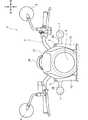
図1は、本発明の一実施形態に係るポジションライト一体型ウィンカ装置を適用した自動二輪車1の左側面図である。図2は、この自動二輪車1の正面図である。自動二輪車1の車体フレームFは、ヘッドパイプF2から車体後方下方に延びる左右一対のメインフレームF1と、メインフレームF1の下方でヘッドパイプF2から車体後方下方に延びる左右一対のハンガフレームF3と、メインフレームF1の後方下部に連結される左右一対のピボットフレームF4とを含む。メインフレームF1の後部には、左右一対の上側パイプF5および下側パイプF6を含んで後方上方に延出するシートフレームSFが連結されている。 FIG. 1 is a left side view of a motorcycle 1 to which a position light integrated winker device according to an embodiment of the present invention is applied. FIG. 2 is a front view of the motorcycle 1. The body frame F of the motorcycle 1 includes a pair of left and right main frames F1 extending downward from the head pipe F2 to the rear rear of the vehicle body, and a pair of left and right hanger frames F3 extending downward from the head pipe F2 to the rear rear of the main frame F1. Includes a pair of left and right pivot frames F4 connected to the lower rear part of the frame F1. A seat frame SF including a pair of left and right upper pipes F5 and a lower pipe F6 and extending rearward and upward is connected to the rear portion of the main frame F1.
メインフレームF1とハンガフレームF3の間にはエンジンEが支持されており、ハンガフレームF3の前部には、ラジエータ11が配設されている。エンジンEの燃焼ガスは、排気管12を介して車幅方向右側のマフラ12aから排出される。 The engine E is supported between the main frame F1 and the hanger frame F3, and a radiator 11 is arranged at the front portion of the hanger frame F3. The combustion gas of the engine E is discharged from the
ピボットフレームF4は、スイングアーム18の前端部を揺動自在に軸支するピボット14を支持している。エンジンEの駆動力は、ドライブチェーン16を介して、スイングアーム18の後端部に回転自在に軸支される後輪WRに伝達される。スイングアーム18の上部には、ドライブチェーン16の上方を覆うチェーンカバー19が取り付けられており、スイングアーム18の後部は、左右一対のリヤクッション23によってシートフレームSFに吊り下げられている。リヤクッション23の前方の下側パイプF6には、左右一対のタンデムステップホルダ17が取り付けられている。 The pivot frame F4 supports a
前輪WFを回転自在に軸支する左右一対のフロントフォーク10は、ヘッドパイプF2の上下の位置でトップブリッジ5およびボトムブリッジ8に支持されており、トップブリッジ5とボトムブリッジ8とを上下で連結するステムシャフト(不図示)が、ヘッドパイプF2に対して回転可能に軸支される。トップブリッジ5の上部には、車幅方向に延びる操向ハンドル3が固定されており、操向ハンドル3にはバックミラー4が取り付けられている。メータ装置26はトップブリッジ5に支持されており、フロントカウル27が取り付けられたヘッドライト6はボトムブリッジ8に支持されている。左右一対の前側のウィンカ装置7(ポジションライト一体型ウィンカ装置7)は、トップブリッジ5の下部でフロントフォーク10から車幅方向外側に延出するアーム28(図2参照)によって支持されている。 A pair of left and right
メインフレームF1の上部には燃料タンク2が支持されており、燃料タンク2の後方にはシート24が配設されている。シート24の下方で、メインフレームF1、上側パイプF5および下側パイプF6で囲まれる位置には、サイドカバー25が配設されている。シート24の後方に配設されるリヤフェンダ22には、尾灯装置21および左右一対の後側ウィンカ装置20が取り付けられている。 A fuel tank 2 is supported on the upper part of the main frame F1, and a
図3は、本実施形態に係る左右一対の前側のポジションライト一体型ウィンカ装置7のうち、右側用のものの正面図である。ポジションライト一体型ウィンカ装置7は左右対称とされるので、以下ではこの右側用のものに関して説明を行う。 FIG. 3 is a front view of a pair of left and right front position light integrated winker devices 7 according to the present embodiment for the right side. Since the position light integrated winker device 7 is symmetrical, the device for the right side will be described below.
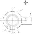
ポジションライト一体型ウィンカ装置7は正面視においてアウタレンズ80が略円形をなし、この円の中心側に円形領域としてウィンカライト発光領域86が形成され、これを囲む円環状の領域としてポジションライト発光領域87が形成されている。本実施形態のポジションライト一体型ウィンカ装置7においてはこのように、従来例のように点状に形成されるウィンカライト発光領域とは異なり、ポジションライト発光領域87がウィンカライト発光領域86を囲むように形成されることで、一定の広さ及び所定の模様形状を確保することが可能となり、ポジションライト発光領域87の視認性を向上させることが可能となる。 In the position light integrated winker device 7, the
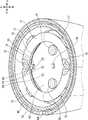
図4は、図3のA−A断面図である。ポジションライト一体型ウィンカ装置7は、その構造に関する主な構成として、半回転楕円体状のハウジング40、内部ユニット50、基板60、導光部材70及びアウタレンズ80を備える。図5は、正面図である図3においてポジションライト一体型ウィンカ装置7からアウタレンズ80を取り外した状態を示す図である。図6は、図5の状態からさらに導光部材70を取り外した状態を示す図である。 FIG. 4 is a cross-sectional view taken along the line AA of FIG. The position light integrated winker device 7 includes a
図7及び図8は共にアウタレンズ80の斜視図である。ここで、図7はアウタレンズ80をポジションライト一体型ウィンカ装置7に取り付ける際の、このウィンカ装置7の内部の側(光源が存在する側)から見た斜視図であり、逆に図8は外部の側から見た斜視図である。 7 and 8 are both perspective views of the
図9は、図5に示されるアウタレンズ80が外された状態のポジションライト一体型ウィンカ装置7の斜視図である。図10は、図3のB−B断面図である。なお、図3のB−B断面の位置は、図5ではC−C断面の位置に対応し、図6ではD−D断面の位置に対応するものである。 FIG. 9 is a perspective view of the position light integrated winker device 7 in a state where the
以下、主に図4を参照しながら適宜、図5ないし図10も参照することにより、本実施形態に係るポジションライト一体型ウィンカ装置7を説明する。 Hereinafter, the position light integrated winker device 7 according to the present embodiment will be described with reference to FIGS. 5 to 10 as appropriate with reference to FIG. 4.
図4にて、樹脂等により形成される半回転楕円体形状のハウジング40には、上方内壁に形成された凸壁部41によって位置決めされたうえで下方の平坦部42のネジ孔よりネジ43を用いて締結されることで、内部ユニット50が固定されている。ハウジング40の前方の最下部には水抜き孔44が形成されている。
In Figure 4, the
内部ユニット50は樹脂等により一体形成され、主な構造として、ポジションライト一体型ウィンカ装置7の光源(1個のウィンカライト光源90と2個のポジションライト光源91,92)や導光部材70等がその内部に配置される略円柱状の内部空間を形成するための内壁部51と、この光源を点灯させるための配線(不図示)を導くためのガイド部52と、を有する。ガイド部52は、その内部に形成される内部空洞53によって配線を、基板60上の光源から、車両後方側においてガイド部52及びハウジング40の間に形成される後方空間45へと導いたうえで、アーム28を介してこの配線をさらに自動二輪車1の車両側へと導くことを可能とする。ガイド部52はさらに、前述した通りのハウジング40に対して内部ユニット50を固定するための機能と、次に述べる基板60を固定する機能と、をも有する。 The
基板60は一対のタッピングビス61,62で締結されることにより内部ユニット50のガイド部52に固定されている。図5や図6に示されるように、基板60は四隅がカットされた略正方形の形状とされ、正面視において内部ユニット50の内壁部51内に形成される円をほぼ遮蔽するようになっている。基板60上には、その中心に1個のウィンカライト光源90が配置され、略正方形の形状の対角上に2個のポジションライト光源91,92が配置されている。これら光源90,91,92はそれぞれLED素子を採用するようにしてよい。基板60上には、3つの配線孔63,64,65が形成され、これによって前述したように内部ユニット50のガイド部52の内部空洞53から光源90,91,92へと配線をガイドすることが可能となっている。 The
こうして、図6にも示されるように、光源90,91,92はポジションライト一体型ウィンカ装置7のアーム28と平行に直線状に並んで配置されることにより、光源90,91,92に対する配線の配策性を向上させることができる。 In this way, as shown in FIG. 6, the
ここで、2個のポジションライト光源91,92は、導光部材70のなす円の直径の両端側の位置に位置するよう、且つ、基板60が形成する略正方形における対角に位置するよう、それぞれが配置されている。導光部材70のなす円の直径の両端側の位置に位置するよう2個のポジションライト光源91,92が配置されることで、2個のみの光源によって効率的に導光部材70の全域を発光させることができる。 Here, the two position light
また、導光部材70のなす円の中央の位置であり、且つ、基板60が形成する略正方形における対角中心の位置に、ウィンカライト光源90が配置されている。これにより、ポジションライト一体型ウィンカ装置7の内部の基板60の限られた面積を活用して、2個のポジションライト光源91,92と、1個のウィンカライト光源90と、の両方をこの基板60上にレイアウトすることができる。 Further, the winkerite
さらに、全ての光源90,91,92が同一の基板60上に配置されていることにより、部品点数の削減を図ることができる。 Further, since all the
導光部材70は、その形状を構成する主な要素として、反射凹部75を有する略トーラス形状部71、4つの脚部72、円周状底部73及び2つの光導入部74を含んで構成され、アクリルやポリカーボネート等によって無色透明または有色透明なものとして一体形成される。 The
導光部材70は、略トーラス形状部71に対して、4つの固定用の脚部72を円の中心から見た放射方向へと突出させて設けた形状とされる。図5に示されるように、4つの脚部72がそれぞれ、略正方形の基板60の4辺に対向する位置において内部ユニット50の内壁部51から突出して形成される棚部54に接着や溶着等によって固定されることにより、導光部材70は内部ユニット50の内壁部51に対して固定される。ここで、導光部材70を取り外した状態を表す図6に示されるように、4つの各々の棚部54は互いに平行な両壁部56,56とこれらに垂直な底部57とによって内壁部51から突出して形成されており、この棚部54に対して脚部72が係合したうえで、脚部72は棚部54に固定されることができる。 The
導光部材70が内部ユニット50の内壁部51に対して固定され、且つ、内部ユニット50のガイド部52に基板60が固定されることにより、導光部材70は基板60に近接した位置で基板60に対向して配置される。これにより、図4、図9及び図10に示されるように、基板60上に配置される2つのポジションライト光源91,92も、導光部材70の2個の光導入部74のそれぞれに近接した位置で対向して配置される。 The
また、導光部材70は略トーラス形状部71から突出するこの4つの脚部72に加えてさらに、円周状底部73と、2個の光導入部74と、を有する形状とされる。円周状底部73はトーラス形状部71に接続して基板60寄りの側に突出して設けられ、基板60に面した円周状の反射用の溝構造を有する。2個の光導入部74は、略トーラス形状部71に接続するものとして、2個のポジションライト光源91,92のそれぞれに対向して近接し、且つ、略トーラス形状部71から突出して設けられ、このポジションライト光源91,92による光を導光部材70内に取り込む機能を有する。円周上の光導入部74のある箇所において、円周状底部73は途切れており、形成されていない。 Further, the
図4にも示される通り、2個の光導入部74の近くの位置以外において、トーラス形状部71の断面は、アウタレンズ80に面する側(図中の車両前方側)が略半円状とされ、この反対側の円周状底部73に接続される側(図中の車両後方側)が、その幅が円周状底部73の幅になるよう狭まっていく線形テーパー形状とされる。すなわち、アウタレンズ80の側の略半円の直径よりも円周状底部73のなす幅の方が小さく、これによってトーラス形状部71の円周状底部73に接続される側の断面は線形テーパー形状をなしている。 As shown in FIG. 4, the cross section of the torus-shaped
また、2個の光導入部74に対向する箇所においてそれぞれ、略トーラス形状部71は反射凹部75を有した形状とされる。 Further, the substantially torus-shaped
こうして、ポジションライト光源91,92による光が、対向する2個の光導入部74の各々に入射した後、反射凹部75のなす面で一部が反射されて円周状底部73に形成される反射溝へと向かった後、この反射溝でさらに車両前方側に向かって反射され、略トーラス形状部71の車両前方側の半円面から車両前方に向かって出射することにより、車両前面視において導光部材70の前面側の全域が円環形状(4つの脚部72を除いた円環形状)の発光領域を形成することとなる。この発光領域がポジションライト用透過部82を透過してポジションライト一体型ウィンカ装置7の外部から視認されることで、ウィンカライト発光領域86が形成される。
In this way, after the light from the position light
ここで、円環形状の全域に渡って均一な発光領域が効率的に形成されるように、導光部材70は形成されている。すなわち、導光部材70は反射凹部75及び光導入部74を通る面(図10における断面)によって面対称な形状として構成されており、対称なそれぞれの半円環部分が均一に発光するようにポジションライト光源91,92からの光が均一に分かれて入射することが可能なように、光導入部74は一対の対称な傾斜した光取込面741,742(図4、図10)を有している。この光取込面741,742の傾斜の向き(面の法線で指定される面の傾斜の向き)は、ポジションライト光源91,92の正面(車両正面)に対して、対応する光取込面741,742が属する側の半円環部分に向かって傾斜するような向きとされることにより、対応する半円環部分に対して、光源91,92から離れた位置に対しても効率的に光の入射が可能となっている。 Here, the
なお、導光部材70が面対称な形状として構成されるのは、光源91,92からの光をガイドする機能に関する部分のみでよい。例えば、光をガイドする機能ではなく位置決め機能を有する4つの脚部72のうち1個を仮に省略したとすると、導光部材70はその全体としては面対称な形状ではなくなるが、このように光をガイドする機能とは直接には関係のない部分については、必ずしも面対称でなくともよい。また、面対称な形状であることは、一定の精度内において面対称と判定されるものであればよい。 The
アウタレンズ80はアクリルやポリカーボネート等によって無色透明または有色透明なものとして密に一体形成される。アウタレンズ80は、その断面図を含む図4及び図10並びに斜視図である図7及び図8に示されるように、中心側のウィンカライト用レンズ部81と、これを円環状に取り囲むポジションライト用透過部82とを有し、中心軸に関して回転対称な形状とされる。 The
アウタレンズ80の外周側にはアウタレンズ外縁部84及びアウタレンズ内縁部85の2つの縁部が形成されている。アウタレンズ外縁部84がハウジング40のハウジング縁部46に接着または溶着等によって固定されることにより、アウタレンズ80はハウジング40に対して固定される。さらに、アウタレンズ内縁部85が内部ユニット50の内壁部51の内部ユニット縁部55に接着または溶着等によって固定されることにより、アウタレンズ80は内部ユニット50に対して固定される。 Two edges, an outer lens
ポジションライト一体型ウィンカ装置7を正面視で見た際の円状のウィンカライト発光領域86及び円環状のポジションライト発光領域87(図3)はそれぞれ、ウィンカライト用レンズ部81を介した1個のウィンカライト光源90による発光と、導光部材70及びポジションライト用透過部82を介した2個のポジションライト光源91,92による発光と、によって形成される。
When the position light integrated winker device 7 is viewed from the front, the circular winker light
図4及び図10に示されるように、ウィンカライト用レンズ部81は、ポジションライト用透過部82と比べて、基板60側(図4での車両後方側)により近くなるように、光源の照射方向(車両前方側)から逆向きの奥まった位置(照射方向で光源寄りの位置)に形成されることにより、アウタレンズ80の中心側には凹部83が形成される。こうして、ウィンカライト用レンズ部81はウィンカライト光源90に対してより近接した位置に配置されたうえで、且つ、ウィンカライト光源90からの光を車両前方へと指向させるレンズカットが施されて形成されていることにより、次の機能が実現される。すなわち、ウィンカライト光源90の光(例えばLEDによる指向性を有するものでよい)は、円(光源90を中心とする円)のより内側にあり近接したウィンカライト用レンズ部81のみへと向かい、円のより外側にあるポジションライト用透過部82へと向かうことは遮断される、という機能である。 As shown in FIGS. 4 and 10, the winker
さらに、このように凹部83を形成してウィンカライト用レンズ部81がウィンカライト光源90に対してより近接した位置に配置されることにより、同時に導光部材70に対してもより近接した位置に配置されることとなり、そのレンズカット面は、導光部材70からの発光の影響がウィンカライト発光領域86内に現れないように、遮断する機能をも有するものである。 Further, by forming the
以上のように、凹部83を形成してウィンカライト用レンズ部81がポジションライト用透過部82よりも奥まって形成されていることにより、円状のウィンカライト発光領域86とその周囲にある円環状のポジションライト発光領域87(図3)とを、それらの境界を明瞭に区別したものとして形成することが可能となる。
As described above, since the
従って、少数の3個の光源90,91,92によりウィンカライト発光領域86とそとポジションライト発光領域87を明瞭に区別して形成可能とされており、しかも、この形成のためには導光部材70及びアウタレンズ80などを以上のように活用することにより、ポジションライト一体型ウィンカ装置7の内部において発光領域を分けるための部屋分け等の構造が不要となる。 Therefore, it is possible to clearly distinguish the winker light
以上、図面を参照して本発明の一実施形態を説明したが、その他の実施形態も可能である。例えば、導光部材70及びこれによって形成されるポジションライト発光領域87は略円環状でなくともよく、中空の略楕円形状、中空の矩形形状、中空の多角形形状等とされ、これによりウィンカライト発光領域86を囲うものとされてもよい。この場合、ウィンカライト発光領域86もこれに応じて楕円形状、矩形形状、多角形形状等とされてもよい。アウタレンズ80の正面視での形状もこれらに整合させた形状としてもよい。 Although one embodiment of the present invention has been described above with reference to the drawings, other embodiments are also possible. For example, the
1…自動二輪車(鞍乗型車両)
7…ポジションライト一体型ウィンカ装置
91,92…ポジションライト光源
90…ウィンカライト光源
40…ハウジング
87…ポジションライト発光領域
86…ウィンカライト発光領域
70…導光部材
28…アーム
60…基板
80…アウタレンズ
82…ポジションライト用透過部
81…ウィンカライト用レンズ部
83…凹部
74…光導入部
73…円周状底部
71…略トーラス形状部
75…反射凹部
741,742…光取込面1 ... Motorcycle (saddle-type vehicle)
7 ... Position light
Claims (10)
Translated fromJapanese前記ポジションライト光源(91,92)の発光で形成されるポジションライト発光領域(87)が前記ウィンカライト光源(90)の発光で形成されるウィンカライト発光領域(86)を囲み、
前記ポジションライト光源(91,92)に対向して配置される、正面視で円環状をなす導光部材(70)を備え、前記ポジションライト光源(91,92)が前記導光部材(70)を照射することにより、前記ポジションライト発光領域(87)が形成され、
前記ポジションライト光源(91,92)は第1光源(91)及び第2光源(92)の2個によって構成され、前記導光部材(70)のなす円の直径の両端側にそれぞれが配置され、
前記第1光源(91)、前記第2光源(92)及び前記ウィンカライト光源(90)が、ポジションライト一体型ウィンカ装置(7)を車体に支持するアーム(28)と平行に直線状に並んで配置されることを特徴とするポジションライト一体型ウィンカ装置。In the position light integrated winker device (7) of a saddle-type vehicle in which a winker light light source (90) and a position light light source (91, 92) are housed in a common housing (40).
Enclose the blinker light emitting region (86) formed by the light emission of the position light emitting area formed by the light emitting (87) is the winker light source (90) of the position light source (91,92),
A light guide member (70) forming an annular shape in a front view is provided so as to face the position light light source (91, 92), and the position light light source (91, 92) is the light guide member (70). The position light light emitting region (87) is formed by irradiating the light emitting region (87).
The position light light source (91, 92) is composed of two light sources (91) and a second light source (92), and each is arranged on both ends of the diameter of the circle formed by the light guide member (70). ,
The first light source (91), the second light source (92), and the winker light light source (90) are linearly arranged in parallel with the arm (28) that supports the position light integrated winker device (7) on the vehicle body. A position light integrated winker device characterized by being arranged in.
前記ポジションライト光源(91,92)の発光で形成されるポジションライト発光領域(87)が前記ウィンカライト光源(90)の発光で形成されるウィンカライト発光領域(86)を囲み、
前記ポジションライト光源(91,92)からの照射を受けるポジションライト用透過部(82)と、前記ウィンカライト光源(90)からの照射を受けるウィンカライト用レンズ部(81)と、を含むアウタレンズ(80)を備え、
前記ウィンカライト用レンズ部(81)が、前記ポジションライト用透過部(82)よりも照射方向で光源寄りの位置に形成されていることにより、前記アウタレンズ(80)の表面側に前記ウィンカライト用レンズ部(81)によって凹部(83)が形成されていることを特徴とするポジションライト一体型ウィンカ装置。In the position light integrated winker device (7) of a saddle-type vehicle in which a winker light light source (90) and a position light light source (91, 92) are housed in a common housing (40).
Enclose the blinker light emitting region (86) formed by the light emission of the position light emitting area formed by the light emitting (87) is the winker light source (90) of the position light source (91,92),
An outer lens (81) including a position light transmitting portion (82) that receives irradiation from the position light light source (91, 92) and a winker light lens portion (81) that receives irradiation from the winker light light source (90). Equipped with 80)
Since the winker light lens portion (81) is formed at a position closer to the light source in the irradiation direction than the position light transmission portion (82), the winker light lens portion (80) is formed on the surface side of the outer lens (80) for the winker light. A position light integrated winker device characterized in that a recess (83) is formed by a lens portion (81).
前記ポジションライト光源(91,92)の発光で形成されるポジションライト発光領域(87)が前記ウィンカライト光源(90)の発光で形成されるウィンカライト発光領域(86)を囲み、
前記ポジションライト光源(91,92)に対向して配置される、正面視で円環状をなす導光部材(70)を備え、前記ポジションライト光源(91,92)が前記導光部材(70)を照射することにより、前記ポジションライト発光領域(87)が形成され、
前記導光部材(70)は、円環形状の円の中心から放射方向へと突出する形状で構成される固定用の脚部(72)を含むことを特徴とするポジションライト一体型ウィンカ装置。In the position light integrated winker device (7) of a saddle-type vehicle in which a winker light light source (90) and a position light light source (91, 92) are housed in a common housing (40).
Enclose the blinker light emitting region (86) formed by the light emission of the position light emitting area formed by the light emitting (87) is the winker light source (90) of the position light source (91,92),
A light guide member (70) forming an annular shape in a front view is provided so as to face the position light light source (91, 92), and the position light light source (91, 92) is the light guide member (70). The position light light emitting region (87) is formed by irradiating the light emitting region (87).
The light guide member (70) is a position light integrated winker device including a fixing leg (72) having a shape protruding from the center of a ring-shaped circle in the radial direction.
前記脚部(72)が係合することによって固定される棚部(54)が前記内壁部(51)から突出して形成されていることを特徴とする請求項3に記載のポジションライト一体型ウィンカ装置。The position light integrated winker according to claim 3, wherein a shelf portion (54) fixed by engaging the leg portion (72) is formed so as to project from the inner wall portion (51). Device.
前記脚部(72)は正面視で前記基板(60)がなす辺に沿って設けられることを特徴とする請求項3または4に記載のポジションライト一体型ウィンカ装置。The position light integrated winker device according to claim 3 or 4, wherein the legs (72) are provided along a side formed by the substrate (60) in a front view.
前記導光部材(70)は、光導入部(74)と、円周状底部(73)と、略トーラス形状部(71)と、を含み、
前記光導入部(74)は、前記ポジションライト光源(91,92)に対向して配置され、前記ポジションライト光源(91,92)からの光が入射されるように配置されており、
前記円周状底部(73)は、当該入射された光を車両前方側に反射するよう構成されており、
前記略トーラス形状部(71)は、当該反射された光を前記導光部材(70)の車両前方側に出射するよう構成されていることを特徴とすることを請求項1ないし7のいずれかに記載のポジションライト一体型ウィンカ装置。A light guide member (70) forming an annular shape in a front view is provided so as to face the position light light source (91, 92), and the position light light source (91, 92) is the light guide member (70). The position light light emitting region (87) is formed by irradiating the light emitting region (87).
The light guide member (70) includes a light introduction portion (74), a circumferential bottom portion (73), and a substantially torus-shaped portion (71).
The light introduction unit (74) is arranged to face the position light light source (91, 92), and is arranged so that the light from the position light light source (91, 92) is incident.
The circumferential bottom portion (73) is configured to reflect the incident light toward the front side of the vehicle.
Any one of claims 1 to 7, wherein the substantially torus-shaped portion (71) is configured to emit the reflected light to the vehicle front side of the light guide member (70). Position light integrated winker device described in.
前記光導入部(74)に入射した光は、前記反射凹部(75)において反射されたうえで、前記円周状底部(73)に向かうよう構成されていることを特徴とする請求項8に記載のポジションライト一体型ウィンカ装置。A reflective recess (75) is formed in the substantially torus-shaped portion (71) at a position facing the light introduction portion (74).
8. The eighth aspect of the present invention is characterized in that the light incident on the light introduction portion (74) is reflected by the reflection recess (75) and then directed toward the circumferential bottom portion (73). The described position light integrated winker device.
前記導光部材(70)は、光導入部(74)を含み、
前記光導入部(74)は、前記ポジションライト光源(91,92)に対向して配置され、前記ポジションライト光源(91,92)からの光が入射されるように配置されており、
前記導光部材(70)は前記ポジションライト光源(91,92)からの光をガイドする部分に関して、面対称な形状として形成されており、
前記光導入部(74)は、当該面対称な形状の一方側及び他方側のそれぞれへと前記ポジションライト光源(91,92)からの入射光を取り入れるために、当該一方側及び他方側に向かってそれぞれ傾斜した、光取込面(741,742)を有することを特徴とする請求項1ないし9のいずれかに記載のポジションライト一体型ウィンカ装置。A light guide member (70) forming an annular shape in a front view is provided so as to face the position light light source (91, 92), and the position light light source (91, 92) is the light guide member (70). The position light light emitting region (87) is formed by irradiating the light emitting region (87).
The light guide member (70) includes a light introduction unit (74).
The light introduction unit (74) is arranged to face the position light light source (91, 92), and is arranged so that the light from the position light light source (91, 92) is incident.
The light guide member (70) is formed in a plane-symmetrical shape with respect to a portion that guides the light from the position light light source (91, 92).
The light introduction unit (74) faces the one side and the other side in order to take in the incident light from the position light light source (91, 92) to each of the one side and the other side of the plane-symmetrical shape. The position light integrated winker device according to any one of claims 1 to 9, wherein each of the winker devices has an inclined light intake surface (741,742).
Priority Applications (2)
| Application Number | Priority Date | Filing Date | Title |
|---|---|---|---|
| JP2019009770AJP6911065B2 (en) | 2019-01-23 | 2019-01-23 | Position light integrated winker device |
| US16/730,001US11021202B2 (en) | 2019-01-23 | 2019-12-30 | Position light-integrated blinker apparatus |
Applications Claiming Priority (1)
| Application Number | Priority Date | Filing Date | Title |
|---|---|---|---|
| JP2019009770AJP6911065B2 (en) | 2019-01-23 | 2019-01-23 | Position light integrated winker device |
Publications (2)
| Publication Number | Publication Date |
|---|---|
| JP2020117071A JP2020117071A (en) | 2020-08-06 |
| JP6911065B2true JP6911065B2 (en) | 2021-07-28 |
Family
ID=71609655
Family Applications (1)
| Application Number | Title | Priority Date | Filing Date |
|---|---|---|---|
| JP2019009770AExpired - Fee RelatedJP6911065B2 (en) | 2019-01-23 | 2019-01-23 | Position light integrated winker device |
Country Status (2)
| Country | Link |
|---|---|
| US (1) | US11021202B2 (en) |
| JP (1) | JP6911065B2 (en) |
Families Citing this family (1)
| Publication number | Priority date | Publication date | Assignee | Title |
|---|---|---|---|---|
| EP3683497A1 (en)* | 2019-01-18 | 2020-07-22 | ZKW Group GmbH | Lighting arrangement for vehicles |
Family Cites Families (20)
| Publication number | Priority date | Publication date | Assignee | Title |
|---|---|---|---|---|
| DE19652159B4 (en)* | 1996-12-14 | 2006-05-18 | Automotive Lighting Reutlingen Gmbh | Lighting device for vehicles |
| DE19739173A1 (en)* | 1997-09-06 | 1999-03-11 | Hella Kg Hueck & Co | Signal light for vehicles |
| JP3839236B2 (en)* | 2000-09-18 | 2006-11-01 | 株式会社小糸製作所 | Vehicle lighting |
| US6471368B1 (en)* | 2001-09-26 | 2002-10-29 | Yu-Chu Lin | Secondary alert light for motor vehicles |
| US6641295B1 (en)* | 2002-05-24 | 2003-11-04 | Wendell Ng-Sell-Quan | Fog light device |
| US6789929B1 (en)* | 2002-09-11 | 2004-09-14 | Dj Auto Components Corp. | Lamp structure |
| US6619829B1 (en)* | 2002-11-05 | 2003-09-16 | Shih Ling Chen | Lighting device for vehicle |
| US7097336B2 (en)* | 2004-05-28 | 2006-08-29 | Yu-Chu Lin | Auxiliary light ring device for a vehicular light |
| JP5004012B2 (en) | 2006-09-08 | 2012-08-22 | 本田技研工業株式会社 | Vehicle turn signal integrated rearview mirror |
| CN101639200A (en)* | 2008-07-30 | 2010-02-03 | 深圳富泰宏精密工业有限公司 | Light conductor and light source device with same |
| TWI454639B (en)* | 2009-12-28 | 2014-10-01 | Hon Hai Prec Ind Co Ltd | Light guide ring structure and backlight module using the same |
| JP5721367B2 (en)* | 2010-08-24 | 2015-05-20 | 株式会社小糸製作所 | Vehicle lighting |
| JP5335760B2 (en)* | 2010-12-10 | 2013-11-06 | 本田技研工業株式会社 | Motorcycle lighting equipment |
| EP2693104B1 (en)* | 2011-03-31 | 2015-08-26 | Honda Motor Co., Ltd. | Lighting device for vehicle |
| US20130051050A1 (en)* | 2011-08-26 | 2013-02-28 | Sonar Auto Parts Co., Ltd. | Vehicle lighting device |
| WO2013060329A1 (en)* | 2011-10-23 | 2013-05-02 | Martin Professional A/S | Illumination device with multi-colored light beam |
| CN105637289B (en)* | 2013-10-05 | 2019-11-26 | 哈曼专业丹麦公司 | Lighting device with rotation zoom lens |
| JP6415165B2 (en)* | 2014-08-04 | 2018-10-31 | 株式会社小糸製作所 | Vehicle lighting |
| TW201610344A (en)* | 2014-09-11 | 2016-03-16 | 鴻海精密工業股份有限公司 | Light emitting diode vehicle lamp |
| JP6176859B2 (en)* | 2015-07-15 | 2017-08-09 | 本田技研工業株式会社 | Turn signal structure of vehicle |
- 2019
- 2019-01-23JPJP2019009770Apatent/JP6911065B2/ennot_activeExpired - Fee Related
- 2019-12-30USUS16/730,001patent/US11021202B2/enactiveActive
Also Published As
| Publication number | Publication date |
|---|---|
| JP2020117071A (en) | 2020-08-06 |
| US11021202B2 (en) | 2021-06-01 |
| US20200231238A1 (en) | 2020-07-23 |
Similar Documents
| Publication | Publication Date | Title |
|---|---|---|
| JP5567435B2 (en) | Vehicle lighting | |
| JP5531153B2 (en) | LIGHTING DEVICE FOR VEHICLE AND MOUNTING STRUCTURE FOR THE DEVICE | |
| JP2008166072A (en) | Light guide and vehicle lamp | |
| JP6290841B2 (en) | Vehicle lighting | |
| JP5897919B2 (en) | Vehicle lighting | |
| JP6616669B2 (en) | Light guide and vehicle lamp | |
| JP6413717B2 (en) | Vehicle lighting | |
| JP6777432B2 (en) | Vehicle lighting | |
| JP2012028156A (en) | Lamp unit for vehicle | |
| JP2015133219A (en) | Vehicular lighting fixture | |
| JP6039101B2 (en) | Additional light structure for projector light assemblies for motorcycles | |
| JP5486175B2 (en) | Taillight device | |
| EP3594564B1 (en) | Lighting device for vehicle | |
| JP6125308B2 (en) | Vehicle taillight device | |
| JP6911065B2 (en) | Position light integrated winker device | |
| JP2007123175A (en) | Lighting fixture unit for vehicular marker light | |
| JP7171413B2 (en) | vehicle lamp | |
| JPWO2018051791A1 (en) | Headlight device | |
| JP2008059901A (en) | Marker lamp for vehicle | |
| JP2011040351A (en) | Lighting fixture for vehicle | |
| JP2008034328A (en) | Vehicular marker lamp | |
| JP5486447B2 (en) | Vehicle lighting | |
| JP2010170983A (en) | Lighting fixture for vehicle | |
| JP2021150210A (en) | Vehicular lighting fixture | |
| JP7324090B2 (en) | Vehicle indicator light |
Legal Events
| Date | Code | Title | Description |
|---|---|---|---|
| A621 | Written request for application examination | Free format text:JAPANESE INTERMEDIATE CODE: A621 Effective date:20190927 | |
| A521 | Request for written amendment filed | Free format text:JAPANESE INTERMEDIATE CODE: A523 Effective date:20191218 | |
| A131 | Notification of reasons for refusal | Free format text:JAPANESE INTERMEDIATE CODE: A131 Effective date:20201118 | |
| A521 | Request for written amendment filed | Free format text:JAPANESE INTERMEDIATE CODE: A523 Effective date:20201225 | |
| TRDD | Decision of grant or rejection written | ||
| A01 | Written decision to grant a patent or to grant a registration (utility model) | Free format text:JAPANESE INTERMEDIATE CODE: A01 Effective date:20210623 | |
| A61 | First payment of annual fees (during grant procedure) | Free format text:JAPANESE INTERMEDIATE CODE: A61 Effective date:20210707 | |
| R150 | Certificate of patent or registration of utility model | Ref document number:6911065 Country of ref document:JP Free format text:JAPANESE INTERMEDIATE CODE: R150 | |
| LAPS | Cancellation because of no payment of annual fees |