JP6910465B2 - DMRS transmission method and communication device - Google Patents
DMRS transmission method and communication deviceDownload PDFInfo
- Publication number
- JP6910465B2 JP6910465B2JP2019552280AJP2019552280AJP6910465B2JP 6910465 B2JP6910465 B2JP 6910465B2JP 2019552280 AJP2019552280 AJP 2019552280AJP 2019552280 AJP2019552280 AJP 2019552280AJP 6910465 B2JP6910465 B2JP 6910465B2
- Authority
- JP
- Japan
- Prior art keywords
- dmrs
- frequency band
- additional
- symbols
- sequence
- Prior art date
- Legal status (The legal status is an assumption and is not a legal conclusion. Google has not performed a legal analysis and makes no representation as to the accuracy of the status listed.)
- Active
Links
Images


Classifications
- H—ELECTRICITY
- H04—ELECTRIC COMMUNICATION TECHNIQUE
- H04L—TRANSMISSION OF DIGITAL INFORMATION, e.g. TELEGRAPHIC COMMUNICATION
- H04L5/00—Arrangements affording multiple use of the transmission path
- H04L5/003—Arrangements for allocating sub-channels of the transmission path
- H04L5/0048—Allocation of pilot signals, i.e. of signals known to the receiver
- H—ELECTRICITY
- H04—ELECTRIC COMMUNICATION TECHNIQUE
- H04B—TRANSMISSION
- H04B1/00—Details of transmission systems, not covered by a single one of groups H04B3/00 - H04B13/00; Details of transmission systems not characterised by the medium used for transmission
- H04B1/69—Spread spectrum techniques
- H04B1/713—Spread spectrum techniques using frequency hopping
- H04B1/7143—Arrangements for generation of hop patterns
- H—ELECTRICITY
- H04—ELECTRIC COMMUNICATION TECHNIQUE
- H04L—TRANSMISSION OF DIGITAL INFORMATION, e.g. TELEGRAPHIC COMMUNICATION
- H04L5/00—Arrangements affording multiple use of the transmission path
- H04L5/0001—Arrangements for dividing the transmission path
- H04L5/0003—Two-dimensional division
- H04L5/0005—Time-frequency
- H04L5/0007—Time-frequency the frequencies being orthogonal, e.g. OFDM(A) or DMT
- H04L5/0012—Hopping in multicarrier systems
- H—ELECTRICITY
- H04—ELECTRIC COMMUNICATION TECHNIQUE
- H04L—TRANSMISSION OF DIGITAL INFORMATION, e.g. TELEGRAPHIC COMMUNICATION
- H04L5/00—Arrangements affording multiple use of the transmission path
- H04L5/003—Arrangements for allocating sub-channels of the transmission path
- H04L5/0048—Allocation of pilot signals, i.e. of signals known to the receiver
- H04L5/0051—Allocation of pilot signals, i.e. of signals known to the receiver of dedicated pilots, i.e. pilots destined for a single user or terminal
- H—ELECTRICITY
- H04—ELECTRIC COMMUNICATION TECHNIQUE
- H04L—TRANSMISSION OF DIGITAL INFORMATION, e.g. TELEGRAPHIC COMMUNICATION
- H04L5/00—Arrangements affording multiple use of the transmission path
- H04L5/003—Arrangements for allocating sub-channels of the transmission path
- H04L5/0058—Allocation criteria
- H04L5/0067—Allocation algorithms which involve graph matching
- H—ELECTRICITY
- H04—ELECTRIC COMMUNICATION TECHNIQUE
- H04L—TRANSMISSION OF DIGITAL INFORMATION, e.g. TELEGRAPHIC COMMUNICATION
- H04L5/00—Arrangements affording multiple use of the transmission path
- H04L5/003—Arrangements for allocating sub-channels of the transmission path
- H04L5/0078—Timing of allocation
- H04L5/0082—Timing of allocation at predetermined intervals
- H—ELECTRICITY
- H04—ELECTRIC COMMUNICATION TECHNIQUE
- H04L—TRANSMISSION OF DIGITAL INFORMATION, e.g. TELEGRAPHIC COMMUNICATION
- H04L5/00—Arrangements affording multiple use of the transmission path
- H04L5/0091—Signalling for the administration of the divided path, e.g. signalling of configuration information
- H04L5/0094—Indication of how sub-channels of the path are allocated
- H—ELECTRICITY
- H04—ELECTRIC COMMUNICATION TECHNIQUE
- H04L—TRANSMISSION OF DIGITAL INFORMATION, e.g. TELEGRAPHIC COMMUNICATION
- H04L5/00—Arrangements affording multiple use of the transmission path
- H04L5/0091—Signalling for the administration of the divided path, e.g. signalling of configuration information
- H04L5/0096—Indication of changes in allocation
- H—ELECTRICITY
- H04—ELECTRIC COMMUNICATION TECHNIQUE
- H04L—TRANSMISSION OF DIGITAL INFORMATION, e.g. TELEGRAPHIC COMMUNICATION
- H04L5/00—Arrangements affording multiple use of the transmission path
- H04L5/02—Channels characterised by the type of signal
- H04L5/06—Channels characterised by the type of signal the signals being represented by different frequencies
- H04L5/10—Channels characterised by the type of signal the signals being represented by different frequencies with dynamo-electric generation of carriers; with mechanical filters or demodulators
- H—ELECTRICITY
- H04—ELECTRIC COMMUNICATION TECHNIQUE
- H04W—WIRELESS COMMUNICATION NETWORKS
- H04W72/00—Local resource management
- H04W72/04—Wireless resource allocation
- H04W72/044—Wireless resource allocation based on the type of the allocated resource
- H04W72/0453—Resources in frequency domain, e.g. a carrier in FDMA
- H—ELECTRICITY
- H04—ELECTRIC COMMUNICATION TECHNIQUE
- H04W—WIRELESS COMMUNICATION NETWORKS
- H04W72/00—Local resource management
- H04W72/20—Control channels or signalling for resource management
Landscapes
- Engineering & Computer Science (AREA)
- Signal Processing (AREA)
- Computer Networks & Wireless Communication (AREA)
- Mobile Radio Communication Systems (AREA)
Description
Translated fromJapanese [関連出願への相互参照]
この出願は、2017年9月8日に国家知識産権局に出願された「DMRS TRANSMISSION METHOD AND COMMUNICATIONS DEVICE」という名称の中国特許出願第201710808095.3号、及び2017年7月17日に中国特許庁に出願された「DMRS TRANSMISSION METHOD AND COMMUNICATIONS DEVICE」という名称の中国特許出願第201710583011.0号の優先権を主張するものであり、それらの全内容を参照により援用する。[Cross-reference to related applications]
This application was filed with the China National Intellectual Property Office on September 8, 2017, and the Chinese patent application No. 201710808095.3 named "DMRS TRANSMISSION METHOD AND COMMUNICATIONS DEVICE" was filed with the China Patent Office on July 17, 2017. It claims the priority of the filed Chinese Patent Application No. 201710583011.0 entitled "DMRS TRANSMISSION METHOD AND COMMUNICATIONS DEVICE", the entire contents of which are incorporated by reference.
[技術分野]
この出願は、通信分野に関し、より具体的には、DMRS送信方法及び通信デバイスに関する。[Technical field]
This application relates to the field of communication, and more specifically to DMRS transmission methods and communication devices.
既存の通信システムでは、データ送信中に、送信端デバイス(例えば、アップリンク送信中の端末デバイス又はダウンリンク送信中のネットワークデバイスである)は、復調参照信号(demodulation reference signal, DMRS)を送信する必要があり、それにより、受信端デバイス(例えば、アップリンク送信中のネットワークデバイス又はダウンリンク送信中の端末デバイスである)は、DMRSに基づいてデータを復調する。 In existing communication systems, during data transmission, the transmitting end device (eg, a terminal device during uplink transmission or a network device during downlink transmission) transmits a demodulation reference signal (DMRS). It is necessary, so that the receiving end device (eg, a network device during uplink transmission or a terminal device during downlink transmission) demodulates the data based on DMRS.
通常では、送信端デバイスは、予め設定されたDMRSパターンに基づいてDMRSを送信する。例えば、ロングタームエボリューション(long term evolution, LTE)システムでは、例えば、通常サイクリックプレフィックス(normal cyclic prefix)について、物理アップリンク共有チャネル(physical uplink shared channel, PUSCH)復調に使用されるDMRSは、通常では、リソーススケジューリングユニットの第4シンボル(symbol)及び第11シンボルを常に占有する。他の例では、新無線(new radio, NR)システムは、迅速なフィードバック要件を有する。したがって、NRシステムにおけるDMRSパターン(pattern)では、DMRSは、リソーススケジューリングユニットの前方部分(front loaded)のシンボルを常に占める。 Normally, the transmitting end device transmits DMRS based on a preset DMRS pattern. For example, in a long term evolution (LTE) system, for example, for a normal cyclic prefix, the DMRS used for physical uplink shared channel (PUSCH) demodulation is usually Will always occupy the 4th and 11th symbols of the resource scheduling unit. In another example, the new radio (NR) system has a quick feedback requirement. Therefore, in the DMRS pattern in the NR system, DMRS always occupies the symbol of the front loaded part of the resource scheduling unit.
新無線(new radio, NR)システムにおけるリソーススケジューリングユニットは、異なるシナリオに基づいて異なるモードに柔軟に変更されてもよい。例えば、リソーススケジューリングユニットは、周波数ホッピングモード、すなわち、リソーススケジューリングユニットにおける周波数ホッピング(frequency hopping)送信に対して変更されてもよく、或いは集約モード、すなわち、複数のリソーススケジューリングユニットの集約(aggregation)送信に対して変更されてもよい。 Resource scheduling units in new radio (NR) systems may be flexibly changed to different modes based on different scenarios. For example, the resource scheduling unit may be modified for frequency hopping mode, i.e., frequency hopping transmission in the resource scheduling unit, or aggregation mode, i.e., aggregation transmission of multiple resource scheduling units. May be changed for.
しかし、リソーススケジューリングユニットのモードが変更されたときに、DMRSが依然として予め設定されたDMRSパターンに基づいてDMRSを常に送信する方式で送信される場合、DMRSリソースの浪費又は受信端の劣った復調性能のような悪影響が引き起こされる。その結果、ネットワーク性能が影響を受ける。 However, when the mode of the resource scheduling unit is changed, if DMRS is still transmitted in a way that always sends DMRS based on a preset DMRS pattern, DMRS resources are wasted or the demodulation performance at the receiving end is inferior. Negative effects such as are caused. As a result, network performance is affected.
この出願は、ネットワーク性能を改善するための、DMRS送信方法及び通信デバイスを提供する。 This application provides DMRS transmission methods and communication devices for improving network performance.
第1の態様によれば、DMRS送信方法が提供される。当該方法は、
通信デバイスにより、リソーススケジューリングユニットの現在のモードを決定するステップであり、現在のモードは、周波数ホッピングモード又は集約モードであり、周波数ホッピングモードは、1つのリソーススケジューリングユニット内のいくつかのシンボルが第1の周波数帯域に位置し、いくつかの他のシンボルが第2の周波数帯域に位置することを示し、集約モードは、複数のリソーススケジューリングユニットの集約送信を示す、ステップと、通信デバイスにより、現在のモードに対応するDMRSパターンを使用することにより、DMRSマッピング又はデマッピングを実行するステップであり、現在のモードに対応するDMRSパターンにおけるDMRSにより占有されるシンボルの位置は、予め設定されたDMRSパターンにおけるDMRSにより占有されるシンボルの位置とは異なる、ステップとを含む。According to the first aspect, a DMRS transmission method is provided. The method is
The step of determining the current mode of the resource scheduling unit by the communication device, the current mode is the frequency hopping mode or the aggregation mode, and the frequency hopping mode has several symbols in one resource scheduling unit. Currently located in one frequency band, indicating that some other symbols are located in the second frequency band, aggregate mode indicates aggregate transmission of multiple resource scheduling units, by steps and communication devices. It is a step to execute DMRS mapping or demapping by using the DMRS pattern corresponding to the mode of, and the position of the symbol occupied by DMRS in the DMRS pattern corresponding to the current mode is the preset DMRS pattern. Includes steps that differ from the position of the symbol occupied by DMRS in.
当該方法は、通信デバイスにより実行されてもよく、通信デバイスは、ネットワークデバイス又は端末デバイスでもよいことが理解されるべきである。 It should be understood that the method may be performed by a communication device, which may be a network device or a terminal device.
この出願のこの実施形態では、シンボルは、時間単位を示し、ここでのシンボルは、代替としてOFDMシンボルと呼ばれてもよく、この出願のこの実施形態はそのことに限定されないことが理解されるべきである。 In this embodiment of this application, it is understood that the symbol represents a unit of time, where the symbol may be referred to as an OFDM symbol as an alternative, and this embodiment of this application is not limited thereto. Should be.
この出願のこの実施形態での1つのリソースユニットは、n個のシンボルを含んでもよく、nは2以上の整数であることが更に理解されるべきである。例えば、nは7、14又は2〜13のいずれかの値であり、この出願のこの実施形態はそのことに限定されない。 It should be further understood that one resource unit in this embodiment of this application may contain n symbols, where n is an integer greater than or equal to 2. For example, n is a value of any of 7, 14 or 2-13, and this embodiment of this application is not limited thereto.
この出願のこの実施形態では、DMRSパターンは、代替としてDMRS分布情報又はDMRS属性と呼ばれてもよく、DMRSパターンは、DMRSにより占有されるシンボルの位置及び数量を示すことができ、この出願のこの実施形態はそのことに限定されないことが理解されるべきである。 In this embodiment of this application, the DMRS pattern may be referred to as DMRS distribution information or DMRS attributes as an alternative, and the DMRS pattern can indicate the position and quantity of symbols occupied by DMRS and of this application. It should be understood that this embodiment is not limited to that.
データを送信するとき、通信デバイスは、現在のモードに対応するDMRSパターンに基づいてDMRSマッピングを実行し、データを受信するとき、通信デバイスは、現在のモードに対応するDMRSパターンに基づいてDMRSデマッピングを実行することが理解されるべきである。 When sending data, the communication device performs DMRS mapping based on the DMRS pattern corresponding to the current mode, and when receiving data, the communication device performs DMRS dede based on the DMRS pattern corresponding to the current mode. It should be understood to perform the mapping.
例えば、通信デバイスはネットワークデバイスであり、アップリンク送信を実行するとき、通信デバイスは、現在のモードに対応するDMRSパターンを使用することにより、DMRSデマッピングを実行し、ダウンリンク送信を実行するとき、通信デバイスは、現在のモードに対応するDMRSパターンを使用することにより、DMRSマッピングを実行する。他の例では、通信デバイスは端末デバイスであり、アップリンク送信を実行するとき、通信デバイスは、現在のモードに対応するDMRSパターンを使用することにより、DMRSマッピングを実行し、ダウンリンク送信を実行するとき、通信デバイスは、現在のモードに対応するDMRSパターンを使用することにより、DMRSデマッピングを実行する。 For example, when the communication device is a network device and performs uplink transmission, the communication device performs DMRS demapping and performs downlink transmission by using the DMRS pattern corresponding to the current mode. , The communication device performs DMRS mapping by using the DMRS pattern corresponding to the current mode. In another example, the communication device is a terminal device, and when performing uplink transmission, the communication device performs DMRS mapping and performs downlink transmission by using the DMRS pattern corresponding to the current mode. When doing so, the communication device performs DMRS demapping by using the DMRS pattern corresponding to the current mode.
この出願のこの実施形態では、予め設定されたDMRSパターンは、代替として、所定のパターン、デフォルトパターン又は第1のDMRSパターンと呼ばれてもよく、現在のモードに対応するDMRSパターンは、代替として、第2のDMRSパターンと呼ばれてもよいことが理解されるべきである。この出願のこの実施形態では、予め設定されたDMRSパターンは、第1のモード(すなわち、非周波数ホッピング及び非集約モード)において使用されるDMRSパターンを示す。 In this embodiment of the application, the preset DMRS pattern may be referred to as a predetermined pattern, default pattern or first DMRS pattern as an alternative, and the DMRS pattern corresponding to the current mode is an alternative. It should be understood that it may be called the second DMRS pattern. In this embodiment of the application, the preset DMRS pattern refers to the DMRS pattern used in the first mode (ie, non-frequency hopping and non-aggregate modes).
従来技術では、通信は、いずれかの送信モードにおいて予め設定されたDMRSパターンを使用することにより実行される。具体的には、DMRSにより占有されるシンボルの位置は、予め設定されたDMRSパターンにおけるDMRSにより占有されるシンボルの位置と同じである。しかし、いくつかの適用シナリオでは、リソーススケジューリングユニットのモードが変更されたとき、DMRSが依然としてDMRSを常に送信する既存の方式で送信される場合、予め設定されたDMRSパターンにおけるDMRSの分布方式は、異なるモードの要件を満たすのに困難であるので、DMRSリソースの浪費又は受信端の劣った復調性能のような悪影響が引き起こされる。その結果、ネットワーク性能が影響を受ける。 In the prior art, communication is performed by using a preset DMRS pattern in either transmission mode. Specifically, the position of the symbol occupied by DMRS is the same as the position of the symbol occupied by DMRS in the preset DMRS pattern. However, in some application scenarios, when the mode of the resource scheduling unit is changed, if DMRS is still sent in the existing way that always sends DMRS, then the distribution method of DMRS in the preset DMRS pattern is Difficulty in meeting the requirements of different modes causes adverse effects such as wasted DMRS resources or poor demodulation performance at the receiving end. As a result, network performance is affected.
しかし、この出願のこの実施形態での異なるモードにおけるDMRSパターンは、予め設定されたパターンとは異なり、DMRSにより占有されるシンボルの位置は、この出願のこの実施形態では、異なるモードに基づいて柔軟に選択できる。したがって、この出願のこの実施形態では、異なるモードの要件が満たされることができ、それにより、ネットワーク性能を改善する。 However, the DMRS pattern in different modes in this embodiment of this application is different from the preset pattern, and the position of the symbols occupied by DMRS is flexible in this embodiment of this application based on the different modes. Can be selected. Therefore, in this embodiment of this application, the requirements of different modes can be met, thereby improving network performance.
通信デバイスがネットワークデバイスであるとき、ネットワークデバイスは、複数の方式で現在のモードを決定してもよい。 When the communication device is a network device, the network device may determine the current mode in multiple ways.
任意選択で、ネットワークデバイスは、端末デバイスにより報告されたチャネル状態情報及びセルのネットワーク状態に基づいて現在のモードを決定してもよい。 Optionally, the network device may determine the current mode based on the channel state information reported by the terminal device and the network state of the cell.
任意選択で、ネットワークデバイスは、端末デバイスにより使用される波形、例えば、シングルキャリア波形又はマルチキャリア波形に基づいて現在のモードを決定してもよい。例えば、端末デバイスがシングルキャリア波形を使用するとき、現在のモードは周波数ホッピングモードでもよく、端末デバイスがマルチキャリア波形を使用するとき、現在のモードは集約モードでもよい。この出願のこの実施形態はそのことに限定されない。例えば、端末デバイスがシングルキャリア波形を使用するとき、現在のモードは、代替として、集約モードでもよい。 Optionally, the network device may determine the current mode based on the waveform used by the terminal device, such as a single carrier waveform or a multicarrier waveform. For example, when the terminal device uses a single carrier waveform, the current mode may be frequency hopping mode, and when the terminal device uses a multicarrier waveform, the current mode may be aggregate mode. This embodiment of this application is not limited to that. For example, when the terminal device uses a single carrier waveform, the current mode may be an aggregate mode as an alternative.
任意選択で、ネットワークデバイスは、サービスタイプに基づいて現在のモードを決定してもよい。サービスタイプは、迅速な復調を要求するサービス、高送信性能を要求するサービス等を含んでもよい。 Optionally, the network device may determine the current mode based on the service type. The service type may include a service that requires rapid demodulation, a service that requires high transmission performance, and the like.
任意選択で、ネットワークデバイスは、端末デバイスにより送信された指示情報に基づいて現在のモードを決定してもよい。具体的には、端末デバイスは、ネットワーク状態又はサービス状態のような現在の状態に基づいて現在のモードを決定してもよく、次いで、端末デバイスは、現在のモードをネットワークデバイスに示す。この場合、端末デバイスは、指示情報をネットワークデバイスに送信し、それにより、ネットワークデバイスは、端末デバイスにより送信された指示情報に基づいて現在のモードを決定する。 Optionally, the network device may determine the current mode based on the instructional information transmitted by the terminal device. Specifically, the terminal device may determine the current mode based on the current state, such as network state or service state, and then the terminal device indicates the current mode to the network device. In this case, the terminal device sends the instruction information to the network device, whereby the network device determines the current mode based on the instruction information transmitted by the terminal device.
任意選択で、第1の態様の実現方式では、通信デバイスはネットワークデバイスであり、当該方法は、通信デバイスにより、第1の指示情報を端末デバイスに送信するステップであり、第1の指示情報は、リソーススケジューリングユニットの現在のモードを決定するために端末デバイスにより使用される、ステップを更に含む。 Arbitrarily, in the implementation method of the first aspect, the communication device is a network device, the method is a step of transmitting the first instruction information to the terminal device by the communication device, and the first instruction information is Includes additional steps used by the terminal device to determine the current mode of the resource scheduling unit.
任意選択で、第1の態様の実現方式では、通信デバイスはネットワークデバイスであり、当該方法は、通信デバイスにより、第2の指示情報を端末デバイスに送信するステップであり、第2の指示情報は、現在のモードに対応するDMRSパターンを示すために使用される、ステップを更に含む。 Arbitrarily, in the implementation method of the first aspect, the communication device is a network device, the method is a step of transmitting the second instruction information to the terminal device by the communication device, and the second instruction information is Includes additional steps, used to indicate the DMRS pattern corresponding to the current mode.
通信デバイスが端末デバイスであるとき、端末デバイスは、複数の方式で現在のモードを決定してもよい。 When the communication device is a terminal device, the terminal device may determine the current mode in a plurality of ways.
任意選択で、端末デバイスは、ネットワークデバイスの指示に基づいて現在のモードを決定してもよい。具体的には、端末デバイスは、ネットワークデバイスにより送信された第1の指示情報を受信してもよく、第1の指示情報は、現在のモードを決定するために端末デバイスにより使用される。第1の指示情報を取得した後に、端末デバイスは、第1の指示情報に従ってリソーススケジューリングユニットの現在のモードを決定してもよい。 Optionally, the terminal device may determine the current mode based on the instructions of the network device. Specifically, the terminal device may receive the first instruction information transmitted by the network device, which is used by the terminal device to determine the current mode. After acquiring the first instruction information, the terminal device may determine the current mode of the resource scheduling unit according to the first instruction information.
第1の指示情報は、現在のモードが集約モード又は周波数ホッピングモードであることを直接的に示してもよいことが理解されるべきである。任意選択で、第1の指示情報は、現在のモードを間接的に示してもよい。例えば、第1の指示情報は、リソーススケジューリングユニットの長さを示し、端末デバイスは、リソーススケジューリングユニットの長さに基づいて現在のモードを決定してもよい。他の例では、第1の指示情報は、現在のサービスタイプを示し、端末デバイスは、サービスタイプに基づいて現在のモードを決定し、この出願のこの実施形態はそのことに限定されない。 It should be understood that the first instructional information may directly indicate that the current mode is an aggregate mode or a frequency hopping mode. Optionally, the first instructional information may indirectly indicate the current mode. For example, the first instructional information indicates the length of the resource scheduling unit, and the terminal device may determine the current mode based on the length of the resource scheduling unit. In another example, the first instructional information indicates the current service type, the terminal device determines the current mode based on the service type, and this embodiment of the application is not limited thereto.
ネットワークデバイスは、ダウンリンク制御情報(downlink control information, DCI)、無線リソース制御(radio resource control, RRC)シグナリング及び媒体アクセス制御(media access control, MAC)制御エレメント(control element, CE)のような複数のタイプのシグナリングを使用することにより、第1の指示情報を端末デバイスに送信してもよいことが理解されるべきである。これはこの出願のこの実施形態では限定されない。 Network devices include multiple downlink control information (DCI), radio resource control (RRC) signaling and media access control (MAC) control elements (CE). It should be understood that the first instructional information may be transmitted to the terminal device by using the type of signaling of. This is not limited to this embodiment of this application.
任意選択で、第1の態様の実現方式では、通信デバイスは端末デバイスであり、当該方法は、通信デバイスにより、ネットワークデバイスにより送信された第1の指示情報を受信するステップであり、第1の指示情報は、リソーススケジューリングユニットの現在のモードを決定するために端末デバイスにより使用される、ステップを更に含み、通信デバイスにより、リソーススケジューリングユニットの現在のモードを決定するステップは、通信デバイスにより、第1の指示情報に従って、現在のモードを決定するステップを含む。 Optionally, in the implementation of the first aspect, the communication device is a terminal device, the method of which is the step of receiving the first instruction information transmitted by the network device by the communication device, the first. The instructional information further comprises a step used by the terminal device to determine the current mode of the resource scheduling unit, and the step of determining the current mode of the resource scheduling unit by the communication device is by communication device. Includes steps to determine the current mode according to the instructional information in 1.
任意選択で、第1の態様の実現方式では、通信デバイスは端末デバイスであり、当該方法は、通信デバイスにより、ネットワークデバイスにより送信された第2の指示情報を受信するステップであり、第2の指示情報は、現在のモードに対応するDMRSパターンを示すために使用される、ステップを更に含む。 Optionally, in the implementation of the first aspect, the communication device is a terminal device, the method of which is the step of receiving the second instruction information transmitted by the network device by the communication device, the second. The instructional information further includes steps used to indicate the DMRS pattern corresponding to the current mode.
ネットワークデバイスは、DCI、RRCシグナリング及びMAC CEのような複数のタイプのシグナリングを使用することにより、第2の指示情報を端末デバイスに送信してもよいことが理解されるべきである。これはこの出願のこの実施形態では限定されない。 It should be understood that the network device may send a second instructional information to the terminal device by using multiple types of signaling such as DCI, RRC signaling and MAC CE. This is not limited to this embodiment of this application.
具体的には、ネットワークデバイスは、ネットワークデバイスが端末デバイスとデータ送信を実行するときにDMRSパターンを決定する必要があるので、ネットワークデバイスは、ネットワークデバイスが端末デバイスとデータ送信を実行するときに使用されるDMRSパターンを端末デバイスに通知し、端末デバイスは、DMRSパターンに基づいてDMRSの時間周波数リソース位置を決定してもよく、次いで、DMRSマッピング又はデマッピングを実行してもよい。 Specifically, the network device needs to determine the DMRS pattern when the network device performs data transmission with the terminal device, so the network device is used when the network device performs data transmission with the terminal device. The DMRS pattern to be generated may be notified to the terminal device, and the terminal device may determine the time frequency resource position of DMRS based on the DMRS pattern, and then perform DMRS mapping or demapping.
任意選択で、端末デバイスは、現在の状態に基づいて現在のモードを決定してもよい。例えば、端末デバイスは、ネットワーク状態又はサービス状態に基づいて現在のモードを決定し、次いで、端末デバイスは、現在のモードをネットワークデバイスに示す。 Optionally, the terminal device may determine the current mode based on the current state. For example, the terminal device determines the current mode based on the network state or service state, and then the terminal device indicates the current mode to the network device.
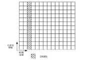
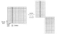
任意選択で、第1の態様の実現方式では、現在のモードは周波数ホッピングモードであり、予め設定されたDMRSパターンにおけるDMRSは、周波数ホッピングなしで1つのリソーススケジューリングユニット内のN個の連続シンボルを占有し、Nは1以上の整数であり、現在のモードに対応するDMRSパターンにおけるDMRSは、第1の周波数帯域内のN1個の連続シンボル及び第2の周波数帯域内のN2個の連続シンボルを占有し、N1は1以上の整数であり、N2は1以上の整数である。Optionally, in the implementation of the first aspect, the current mode is frequency hopping mode, and DMRS in a preset DMRS pattern has N consecutive symbols in one resource scheduling unit without frequency hopping. Occupied, N is an integer greater than or equal to 1, and DMRS in the DMRS pattern corresponding to the current mode is N1contiguous symbol in the 1st frequency band and N 2 contiguous in the 2nd frequency band. Occupy a symbol, N1 is an integer greater than orequal to 1, and N 2 is an integer greater than or equal to 1.
この出願のこの実施形態では、周波数ホッピングモードにおいて、2つの周波数帯域のチャネル状態は異なる。したがって、この出願のこの実施形態では、DMRSは各周波数帯域で送信され、それにより、受信端デバイスは、周波数帯域内のDMRSに基づいて対応するデータを復調でき、それにより、データ復調精度を改善し、復調性能を改善する。In this embodiment of this application, in the frequency hopping mode, the channel states of the two frequency bands are different. Therefore, in this embodiment of this application, the DMRS is transmitted in each frequency band, whereby the receiving enddevice can demodulate the corresponding data based on the DMRS in the frequency band, thereby improving the data demodulation accuracy. And improve the demodulation performance.
任意選択で、第1の態様の実現方式では、N1=N2であり、第1の周波数帯域内のN1個のシンボルの位置は、第2の周波数帯域内のN2個のシンボルの位置と対称的である。Arbitrarily, in the implementation of the first aspect, N1 = N2 , and the position of the N1 symbol in the first frequency band is that of the N2 symbols in the second frequency band. It is symmetrical with the position.
したがって、この出願のこの実施形態では、2つの周波数帯域内のDMRSは対称的に配置され、それにより、受信端デバイスは、同じ方式で2つの周波数帯域でデータ復調を実行でき、それにより、復調の複雑さを低減し、ネットワーク性能を改善する。 Therefore, in this embodiment of this application, DMRSs within the two frequency bands are symmetrically arranged so that the receiving end device can perform data demodulation in the two frequency bands in the same manner, thereby demodulating. Reduces complexity and improves network performance.
任意選択で、第1の態様の実現方式では、N2個のシンボルは、第2の周波数帯域内の第1シンボルを含む。Optionally, in the implementation of the first aspect, the Ntwo symbols include the first symbol in the second frequency band.
受信端デバイスは、受信端デバイスがDMRSを取得した後にのみデータを復調してもよい。したがって、この出願のこの実施形態では、DMRSは、第2の周波数帯域内の第1シンボルを占有するように設定され、それにより、受信端デバイスは、最初にDMRSを取得でき、次いで、データを迅速に復調できる。The receiving end device may demodulate the data only after the receiving end device has acquired the DMRS. Therefore, in this embodiment of this application, the DMRS is set to occupy the first symbol in the second frequency band, whereby the receiving enddevice can first acquire the DMRS and then the data. It can be demodulated quickly.
N2個のシンボルの位置は、さらに、第2の周波数帯域内のいずれかの位置でもよく、この出願のこの実施形態はそのことに限定されないことが理解されるべきである。It should be understood that the position of the Ntwo symbols may further be any position within the second frequency band, and this embodiment of this application is not limited thereto.
例えば、N2個のシンボルの位置は、第2の周波数帯域の前半部分にあるか、或いはN2個のシンボルのうち第1シンボルは、第2の周波数帯域の前半部分に位置する。例えば、N2=2であり、2つのシンボルは、第2の周波数帯域内の第2シンボル及び第3シンボル又は第3シンボル及び第4シンボルでもよく、この出願のこの実施形態はそのことに限定されない。For example,the position of the N 2 symbols is in the first half of the second frequency band, or the first of the N2 symbols is in the first half of the second frequency band. For example, N2 = 2, and the two symbols may be the second and third symbols or the third and fourth symbols in the second frequency band, and this embodiment of this application is limited thereto. Not done.
任意選択で、第1の態様の実現方式では、N1個のシンボルは、第1の周波数帯域内の第1の領域内の第1シンボルを含み、第1の領域は、データ及びDMRSにより占有されるシンボルを含む。Optionally, the implementation method of the first aspect, N1 symbols includes a first first symbol in the first region in the frequency band, the first region is occupied by the data and DMRS Includes symbols to be.
この出願において、第1の領域は、リソーススケジューリングユニット内にあり且つデータ及びDMRSを運ぶために使用されるシンボルを含むことが理解されるべきである。 In this application, it should be understood that the first area contains symbols that are within the resource scheduling unit and are used to carry data and DMRS.
N1個のシンボルは、第1の領域内の第1シンボルを含み、それにより、迅速な復調を実現する。N1 symbol contains the 1st symbol in the 1st region, thereby achieving rapid demodulation.
任意選択で、第1の態様の実現方式では、N1=N2=1又はN1=N2=2である。Arbitrarily, in the implementation of the first aspect, N1 = N2 = 1 or N1 = N2 = 2.
具体的には、各シーケンスは、1つ又は2つのシンボルを占有するが、この出願のこの実施形態はそのことに限定されない。代替として、或るシーケンスが1つのシンボルを占有し、他のシーケンスが2つのシンボルを占有する。 Specifically, each sequence occupies one or two symbols, but this embodiment of the application is not limited thereto. Alternatively, one sequence occupies one symbol and the other sequence occupies two symbols.
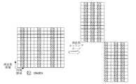
任意選択で、第1の態様の実現方式では、現在のモードは周波数ホッピングモードであり、予め設定されたDMRSパターンにおけるDMRSは、周波数ホッピングなしで1つのリソーススケジューリングユニット内のM個の連続シンボル及びK個の連続シンボルを占有し、M個のシンボルはK個のシンボルに隣接せず、現在のモードに対応するDMRSパターンにおけるDMRSは、第1の周波数帯域内のシンボルのうちM1個の連続シンボル及びK1個の連続シンボルと、第2の周波数帯域内のM2個の連続シンボル及びK2個の連続シンボルとを占有し、M1個のシンボルはK1個のシンボルに隣接せず、M2個のシンボルはK2個のシンボルに隣接せず、M、K、M1、K1、M2及びK2は1以上の整数である。Optionally, the implementation method of the first aspect, acurrent modefrequency hopping mode, the DMRS in DMRS pattern set in advance, M consecutive symbols in one resource scheduling unit without frequency hopping And K consecutive symbols are occupied, M symbols are not adjacent to K symbols, and DMRS in the DMRS pattern corresponding to the current mode is M1 of the symbols in the first frequency band. Occupies a contiguous symbol and a K1contiguous symbol, and an M 2 contiguous symbol and a K2 contiguous symbol in the second frequency band, with the M1 symbol adjacent to the K1 symbol. However, M2 symbols arenot adjacent to K 2 symbols, and M, K, M1 , K1 , M2 and K2 are integers greater than or equal to 1.
M個のシンボルはK個のシンボルの前に位置し、M1個のシンボルはK1個のシンボルの前に位置し、M2個のシンボルはK2個のシンボルの前に位置することが理解されるべきである。M symbols can be placed before K symbols, M1 symbol canbe placed before K 1 symbol, and M2 symbols can be placed beforeK 2 symbols. Should be understood.
任意選択で、第1の態様の実現方式では、K1個のシンボルは、第1の周波数帯域内の最後のシンボル、最後から2番目のシンボル又は最後から3番目のシンボルを含む。Optionally, in the implementation of the first aspect, the K1 symbol comprises the last symbol in the first frequency band, the penultimate symbol, or the penultimate third symbol.
K1個のシンボルは、受信端がデータをより良く復調することを可能にするために、第1の周波数帯域の後半部分に配置され、それにより、システム性能を改善する。The K1 symbol is placed in the second half of the first frequency band to allow the receiving end to better demodulate the data, thereby improving system performance.
任意選択で、第1の態様の実現方式では、M1個のシンボルは、第1の周波数帯域内の第1の領域内の第1シンボルを含み、第1の領域は、データ及びDMRSにより占有されるシンボルを含む。Optionally, the implementation method of the first aspect, M1 symbols includes a first first symbol in the first region in the frequency band, the first region is occupied by the data and DMRS Includes symbols to be.
M1個のシンボルは、第1の周波数帯域内の第1の領域内の第1シンボルを含み、それにより、迅速な復調を実現する。M1 symbols includes afirst first symbol in the first region in the frequency band, thereby realizing rapid demodulation.
任意選択で、第1の態様の実現方式では、M2個のシンボルは、第2の周波数帯域の第1シンボルを含む。Optionally, in the implementation of the first aspect, the M2 symbols include the first symbol in the second frequency band.
任意選択で、第1の態様の実現方式では、M1=Mであり、M1個のシンボルの位置は、M個のシンボルの位置と同じであり、K1個のシンボルは、第1の周波数帯域内の最後のシンボルを含み、M2個のシンボルは、第1の周波数帯域内の第1シンボルを含み、K2=Kであり、K2個のシンボルの位置は、K個のシンボルの位置と同じであるか、或いはK2個のシンボルの位置は、予め設定された位置である。Optionally, the implementation method of the first aspect, an M1 = M, the position of the M1 symbols are the same as the location of the M symbols, K1 symbols, the first wherein the last symbol in the frequency band, M2 symbols includes a first first symbol in the frequency band is K2 = K, the position of the K2 symbols are K symbolsThe position of the K 2 symbol, which is the same as the position of, is a preset position.
任意選択で、第1の態様の実現方式では、M1=Mであり、M1個のシンボルの位置は、M個のシンボルの位置と同じであり、
K1個のシンボルは、全体のリソーススケジューリングユニット内の第7シンボルを含み、全体のリソーススケジューリングユニットは、第1の周波数帯域で占有されるシンボルと第2の周波数帯域で占有されるシンボルとの和を含み、全体のリソーススケジューリングユニットは、14個のシンボルを含み、
M2個のシンボルは、全体のリソーススケジューリングユニット内の第8シンボルを含み、
K2=Kであり、K2個のシンボルの位置は、K個のシンボルの位置と同じであるか、或いはK2個のシンボルの位置は、予め設定された位置である。Optionally, the implementation method of the first aspect, an M1 = M, the position of the M1 symbols are the same as the location of the M symbols,
K1 symbol contains the 7th symbol in the whole resource scheduling unit, and the whole resource scheduling unit has a symbol occupied by the 1st frequency band and a symbol occupied by the 2nd frequency band. Including the sum, the entire resource scheduling unit contains 14 symbols
M2 symbols contain the 8th symbol in the entire resource scheduling unit
A K2 = K, the position of the K2 symbols may be the same as the position of the K symbols, or the position of the K2 symbols are pre-set position.
この出願のこの実施形態では、周波数ホッピングモードにおいて、チャネル状態が比較的大きく変動するときに正確なデータ復調を確保するために、2つのグループのDMRSは、2つの周波数帯域のそれぞれにおいて送信される。 In this embodiment of this application, in frequency hopping mode, two groups of DMRS are transmitted in each of the two frequency bands to ensure accurate data demodulation when the channel state fluctuates relatively significantly. ..
任意選択で、第1の態様の実現方式では、M1=M2であり、K1=K2であり、第1の周波数帯域内のM1個のシンボル及びK1個のシンボルの位置は、第2の周波数帯域内のM2個のシンボル及びK2個のシンボルの位置と対称的である。Arbitrarily, in the implementation of the first aspect, M1 = M2 and K1 = K2 , and the positions ofthe M 1 symbol and the K1 symbol in the first frequency band are , Symmetrical to the positionof the M 2 and K2 symbols in the second frequency band.
この出願のこの実施形態では、2つの周波数帯域内のDMRSは対称的に配置され、それにより、受信端デバイスは、同じ方式で2つの周波数帯域でデータ復調を実行でき、それにより、復調の複雑さを低減し、ネットワーク性能を改善する。 In this embodiment of the application, the DMRSs within the two frequency bands are symmetrically arranged so that the receiving end device can perform data demodulation in the two frequency bands in the same manner, thereby complicating the demodulation. Reduce bandwidth and improve network performance.
任意選択で、第1の態様の実現方式では、M2個のシンボルは、第2の周波数帯域内の第1シンボルを含む。Optionally, in the implementation of the first aspect, the M2 symbols include the first symbol in the second frequency band.
受信端は、受信端がDMRSを取得した後にのみデータを復調してもよい。したがって、この出願のこの実施形態では、DMRSは、第2の周波数帯域内の第1シンボルを占有し、それにより、受信端デバイスは、最初にDMRSを取得し、次いで、迅速な復調を実行でき、それにより、迅速な復調の要件を満たす。The receiving end may demodulate the data only after the receiving end has acquired the DMRS. Therefore, in this embodiment of this application, the DMRS occupies the first symbol in the second frequency band, which allows the receiving enddevice to first acquire the DMRS and then perform rapid demodulation. , Thereby meeting the requirements for rapid demodulation.
M2個のシンボルの位置は、さらに、第2の周波数帯域内のいずれかの位置でもよく、この出願のこの実施形態はそのことに限定されないことが理解されるべきである。It should be understood that the position of the M2 symbols may further be any position within the second frequency band, and this embodiment of this application is not limited thereto.
例えば、M2個のシンボルの位置は、第2の周波数帯域の前半部分にあるか、或いはM2個のシンボルのうち第1シンボルは、第2の周波数帯域の前半部分に位置する。例えば、M2=2であり、2つのシンボルは、第2の周波数帯域内の第2シンボル及び第3シンボル又は第3シンボル及び第4シンボルでもよく、この出願のこの実施形態はそのことに限定されない。For example,the position of the M 2 symbols is in the first half of the second frequency band, orthe first symbol of the M 2 symbols is in the first half of the second frequency band. For example, M2 = 2, and the two symbols may be the second and third symbols or the third and fourth symbols in the second frequency band, and this embodiment of this application is limited thereto. Not done.
任意選択で、第1の態様の実現方式では、予め設定されたDMRSパターンにおけるDMRSは、周波数ホッピングなしで1つのリソーススケジューリングユニット内のP個の連続シンボルを更に占有し、P個のシンボルはM個のシンボルにもK個のシンボルにも隣接せず、
現在のモードに対応するDMRSパターンにおけるDMRSは、第1の周波数帯域内のシンボルのうちP1個の連続シンボルと、第2の周波数帯域内のP2個の連続シンボルとを更に占有し、P1個のシンボルはM1個のシンボルにもK1個のシンボルにも隣接せず、P2個のシンボルはM2個のシンボルにもK2個のシンボルにも隣接せず、P、P1及びP2は1以上の整数である。Optionally, in the implementation of the first aspect, DMRS in a preset DMRS pattern further occupies P consecutive symbols in one resource scheduling unit without frequency hopping, where P symbols are M. Not adjacent to Neither symbols nor K symbols,
DMRS in DMRS pattern corresponding to the current mode, further occupy the P1 consecutive symbols of a symbol in a first frequency band, and a P2 consecutive symbols of the second frequency band, POne symbol is not adjacent toM 1 symbol or K1symbol, P 2 symbols arenot adjacent to M 2 symbols or K2 symbols, P, P1 and P2 are integers greater than or equal to 1.
この出願のこの実施形態では、周波数ホッピングモードにおいて、チャネル状態が比較的大きく変動するときに正確なデータ復調を確保するために、3つのグループのDMRSは、2つの周波数帯域のそれぞれにおいて送信される。 In this embodiment of the application, in frequency hopping mode, three groups of DMRS are transmitted in each of the two frequency bands to ensure accurate data demodulation when the channel state fluctuates relatively significantly. ..
この出願のこの実施形態での予め設定されたDMRSパターンにおけるDMRSは、L個のグループのシンボルを占有してもよく、Lは2、3、4又はより大きい値でもよいことが理解されるべきである。同様に、周波数ホッピングモードにおいて、現在のモードに対応するDMRSパターンにおけるDMRSは、各周波数帯域でL個のグループのシンボルを占有する。 It should be understood that DMRS in the preset DMRS pattern in this embodiment of this application may occupy symbols in a group of L, where L may be a value of 2, 3, 4 or greater. Is. Similarly, in frequency hopping mode, DMRS in the DMRS pattern corresponding to the current mode occupies L group symbols in each frequency band.
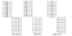
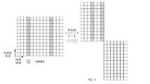
任意選択で、第1の態様の実現方式では、現在のモードは集約モードであり、複数のリソーススケジューリングユニットの数量はYであり、Yは2以上の整数であり、
予め設定されたDMRSパターンにおけるDMRSは、Y個のリソーススケジューリングユニットのそれぞれにおいて少なくとも1つの連続シンボルを占有し、
現在のモードに対応するDMRSパターンにおけるDMRSは、Y個のリソーススケジューリングユニットの最初のY1個のリソーススケジューリングユニットのそれぞれにおいて少なくとも1つの連続シンボルを占有し、Y1は1以上且つY未満の整数である。Optionally, in the implementation of the first aspect, the current mode is aggregate mode, the quantity of multiple resource scheduling units is Y, and Y is an integer greater than or equal to 2.
DMRS in the preset DMRS pattern occupies at least one continuous symbol in each of the Y resource scheduling units.
DMRS in the DMRS pattern corresponding to the current mode occupies at least one consecutive symbol in each ofthe first Y 1resource scheduling units in Y resource scheduling units, where Y 1 is an integer greater than or equal to 1 and less than Y. Is.
この出願のこの実施形態では、集約モードにおいて、DMRSは、集約送信におけるY個のリソーススケジューリングユニットの最初のY1個のリソーススケジューリングユニット内のシンボルのみを占有し、それにより、DMRSにより占有されるリソースを低減し、リソースの浪費を回避し、ネットワーク性能を改善する。In this embodiment of the application, in aggregate mode, the DMRSoccupies only the symbols in the first Y 1 resource scheduling unit of the Y resource scheduling units in the aggregate transmission, thereby being occupied by the DMRS. Reduce resources, avoid wasting resources, and improve network performance.
任意選択で、第1の態様の実現方式では、現在のモードは集約モードであり、複数のリソーススケジューリングユニットの数量はYであり、予め設定されたDMRSパターンにおけるDMRSは、Y個のリソーススケジューリングユニットのそれぞれにおいてL個のグループのシンボルを占有し、Lは2以上の整数であり、L個のグループのシンボルは互いに隣接せず、L個のグループのシンボルのそれぞれは、少なくとも1つの連続シンボルを含み、現在のモードに対応するDMRSパターンにおけるDMRSは、Y個のリソーススケジューリングユニットのそれぞれにおいてL1個のグループのシンボルを占有し、L1はL未満の整数であり、L1個のグループのシンボルは互いに隣接せず、L1個のグループのシンボルのそれぞれは、少なくとも1つの連続シンボルを含む。Optionally, in the implementation of the first aspect, the current mode is the aggregation mode, the quantity of multiple resource scheduling units is Y, and the DMRS in the preset DMRS pattern is Y resource scheduling units. Each of the L group symbols occupies L groups of symbols, L is an integer greater than or equal to 2, the L group symbols are not adjacent to each other, and each of the L group symbols each has at least one continuous symbol. The DMRS in the DMRS pattern that includes and corresponds to the current mode occupies the symbolof the L 1group in each of the Y resource scheduling units, where L 1 is an integer less than L and of the L1 group. symbols each symbol not adjacent, L1 groups. each other, including at least one successive symbols.
この出願のこの実施形態では、集約モードにおいて、DMRSは、集約送信におけるY個のリソーススケジューリングユニットのそれぞれにおいてL1個のグループのシンボルのみを占有し、それにより、DMRSにより占有されるリソースを低減し、リソースの浪費を回避し、ネットワーク性能を改善する。In this embodiment of the application, in aggregate mode, DMRSoccupies only L 1 group of symbols in each of the Y resource scheduling units in aggregate transmission, thereby reducing the resources occupied by DMRS. And avoid wasting resources and improve network performance.
任意選択で、第1の態様の実現方式では、現在のモードは集約モードであり、複数のリソーススケジューリングユニットの数量はYであり、予め設定されたDMRSパターンにおけるDMRSは、Y個のリソーススケジューリングユニットのそれぞれにおいてL個のグループのシンボルを占有し、現在のモードに対応するDMRSパターンにおけるDMRSは、Y個のリソーススケジューリングユニットのそれぞれにおいてL個のグループのシンボルを占有し、Lは2以上の整数であり、L個のグループのシンボルは互いに隣接せず、L個のグループのシンボルのそれぞれは、少なくとも1つの連続シンボルを含み、予め設定されたDMRSパターンにおけるDMRSにより占有されるY*L個のグループのシンボルのうちいずれか2つの隣接するグループのシンボルの間の間隔間の最大の差は、R個のシンボルであり、現在のモードに対応するDMRSパターンにおけるDMRSにより占有されるY*L個のグループのシンボルのうちいずれかの2つの隣接するグループのシンボルの間の間隔間の最大の差は、S個のシンボルであり、S<Rである。 Optionally, in the implementation of the first aspect, the current mode is the aggregation mode, the quantity of multiple resource scheduling units is Y, and the DMRS in the preset DMRS pattern is Y resource scheduling units. Each of them occupies L group symbols, DMRS in the DMRS pattern corresponding to the current mode occupies L group symbols in each of Y resource scheduling units, and L is an integer of 2 or more. L groups of symbols are not adjacent to each other, and each of the L group symbols contains at least one contiguous symbol of Y * L occupied by DMRS in a preset DMRS pattern. The maximum difference between the intervals between any two adjacent group symbols in a group is R symbols, Y * L occupied by DMRS in the DMRS pattern corresponding to the current mode. The maximum difference between the intervals between the symbols of any two adjacent groups of the symbols in the group is S symbols, S <R.
したがって、この出願のこの実施形態では、集約モードにおいて、集約送信におけるY個のリソーススケジューリングユニット内にあり且つDMRSにより占有されるシンボルは、比較的均一に分布し、それにより、復調性能を改善し、リソースの浪費を回避し、ネットワーク性能を改善する。 Therefore, in this embodiment of this application, in aggregate mode, the symbols within the Y resource scheduling units in the aggregate transmission and occupied by DMRS are relatively evenly distributed, thereby improving demodulation performance. , Avoid wasting resources and improve network performance.
DMRSにより占有される1つのグループのシンボル内のシンボルの数量はここでは限定されず、1つのグループのシンボルは、少なくとも1つのシンボルを含んでもよく、例えば、1つのシンボル、2つのシンボル又は3つのシンボルを含んでもよいことが理解されるべきである。この出願のこの実施形態はそのことに限定されない。 The number of symbols within a group of symbols occupied by DMRS is not limited herein and a group of symbols may include at least one symbol, eg, one symbol, two symbols or three. It should be understood that symbols may be included. This embodiment of this application is not limited to that.
第2の態様によれば、DMRS送信方法が提供される。当該方法は、通信デバイスにより、追加DMRSの指示情報を使用することにより、周波数ホッピングモードに対応するDMRSパターンを決定するステップであり、追加DMRSは、前方部分のDMRSの後に位置するDMRSであり、指示情報は、以下のもの、すなわち、追加DMRSが存在するか否か、追加DMRSの数量及び追加DMRSの位置のうち少なくとも1つを示すために使用され、周波数ホッピングモードは、1つのリソーススケジューリングユニット内のいくつかのシンボルが第1の周波数帯域に位置し、いくつかの他のシンボルが第2の周波数帯域に位置することを示す、ステップと、通信デバイスにより、DMRSパターンを使用することにより、DMRSマッピング又はデマッピングを実行するステップとを含む。 According to the second aspect, a DMRS transmission method is provided. The method is a step of determining the DMRS pattern corresponding to the frequency hopping mode by using the instruction information of the additional DMRS by the communication device, and the additional DMRS is the DMRS located after the DMRS of the front part. The instructional information is used to indicate the following: whether additional DMRS is present, the quantity of additional DMRS and at least one of the locations of the additional DMRS, and the frequency hopping mode is one resource scheduling unit. By using the DMRS pattern, by step and communication device, which indicates that some of the symbols are located in the first frequency band and some other symbols are located in the second frequency band. Includes steps to perform DMRS mapping or demapping.
NRにおいて、前半部分のみがDMRSを有し、後半部分が周波数ホッピング後にパイロットを有さない場合、データは通常では復調できないことに留意すべきである。周波数ホッピングが考慮され、DMRSが後半部分に対して独立して設計される場合、DMRS設計の複雑さが増加し、システム実現の複雑さが増加する。 It should be noted that in NR, if only the first half has DMRS and the second half has no pilot after frequency hopping, the data cannot normally be demodulated. If frequency hopping is taken into account and DMRS is designed independently for the second half, the complexity of DMRS design increases and the complexity of system implementation increases.
この出願のこの実施形態では、周波数ホッピングモードに対応するDMRSパターンは、システムに存在するパラメータ、すなわち、追加DMRSの指示情報に基づいて柔軟に決定でき、それにより、実現の複雑さを低減し、システム性能を改善する。 In this embodiment of this application, the DMRS pattern corresponding to the frequency hopping mode can be flexibly determined based on the parameters present in the system, i.e. the additional DMRS instruction information, thereby reducing the complexity of implementation. Improve system performance.
任意選択で、実現方式では、追加DMRSが存在しないことを示すために指示情報が使用されるとき、DMRSパターンにおけるDMRSは、第1の周波数帯域内の1つのシーケンスのシンボル及び第2の周波数帯域内の1つのシーケンスのシンボルを占有し、1つのシーケンスのシンボルは、少なくとも1つの連続シンボルを含む。 Optionally, in the implementation, when the directive information is used to indicate that no additional DMRS is present, the DMRS in the DMRS pattern is a symbol of one sequence within the first frequency band and the second frequency band. Occupies the symbols of one sequence within, and the symbols of one sequence contain at least one contiguous symbol.
任意選択で、実現方式では、第1の周波数帯域内の1つのシーケンスのシンボルは、第1の周波数帯域内の第1の領域内の第1シンボルを含み、第1の領域は、データ及びDMRSにより占有されるシンボルを含む。 Optionally, in the implementation, the symbols of one sequence within the first frequency band include the first symbol within the first region within the first frequency band, the first region being the data and DMRS. Includes symbols occupied by.
任意選択で、実現方式では、第2の周波数帯域内の1つのシーケンスのシンボルは、第2の周波数帯域内の第1シンボルを含む。 Optionally, in the implementation, the symbols of one sequence within the second frequency band include the first symbol within the second frequency band.
任意選択で、実現方式では、追加DMRSが存在することを示すために指示情報が使用されるとき、DMRSパターンにおけるDMRSにより占有される第1の周波数帯域内のシンボルのシーケンスの数量及び位置と、DMRSパターンにおけるDMRSにより占有される第2の周波数帯域内のシンボルのシーケンスの数量及び位置とは、指示情報により示されるシーケンスの数量及び位置と、前方部分のDMRSの指示情報により示されるシーケンスの数量及び位置と同じである。 Optionally, in the implementation scheme, the quantity and position of the sequence of symbols in the first frequency band occupied by the DMRS in the DMRS pattern, when the directive information is used to indicate the presence of additional DMRS. The quantity and position of the sequence of symbols in the second frequency band occupied by DMRS in the DMRS pattern are the quantity and position of the sequence indicated by the instruction information and the quantity and position of the sequence indicated by the instruction information of DMRS in the front part. And the same as the position.
例えば、DMRSにより占有される第1の周波数帯域内のシンボルのシーケンスの数量及び位置は、前方部分のDMRSの指示情報により示されるDMRSシーケンスの数量及び位置と同じであり、DMRSにより占有される第1の周波数帯域内のシンボルのシーケンスの数量及び位置は、追加DMRSの指示情報により示されるDMRSシーケンスの数量及び位置と同じである。 For example, the quantity and position of the sequence of symbols in the first frequency band occupied by DMRS is the same as the quantity and position of the DMRS sequence indicated by the DMRS instruction information in the front part, and the number and position occupied by DMRS. The quantity and position of the sequence of symbols within the frequency band of 1 is the same as the quantity and position of the DMRS sequence indicated by the additional DMRS instruction information.
任意選択で、実現方式では、追加DMRSが存在することを示すために指示情報が使用されるとき、
DMRSパターンにおけるDMRSは、第1の周波数帯域内の2つの不連続なシーケンスのシンボルと、第2の周波数帯域内の2つの不連続なシーケンスのシンボルとを占有するか、DMRSパターンにおけるDMRSは、第1の周波数帯域内の2つの不連続なシーケンスのシンボルと、第2の周波数帯域内の1つのシーケンスのシンボルとを占有するか、或いはDMRSパターンにおけるDMRSは、第1の周波数帯域内の1つのシーケンスのシンボルと、第2の周波数帯域内の2つの不連続なシーケンスのシンボルとを占有し、2つのシーケンスのシンボルのそれぞれは、少なくとも1つの連続シンボルを含み、1つのシーケンスのシンボルは、少なくとも1つの連続シンボルを含む。Optionally, when the implementation method uses instructional information to indicate the presence of additional DMRS,
DMRS in the DMRS pattern occupies two discontinuous sequence symbols in the first frequency band and two discontinuous sequence symbols in the second frequency band, or DMRS in the DMRS pattern It occupies two discontinuous sequence symbols in the first frequency band and one sequence symbol in the second frequency band, or DMRS in the DMRS pattern is 1 in the first frequency band. It occupies a symbol of one sequence and a symbol of two discontinuous sequences in the second frequency band, each of the symbols of the two sequences contains at least one continuous symbol, and the symbol of one sequence is Contains at least one continuous symbol.
任意選択で、実現方式では、DMRSパターンにおけるDMRSが第1の周波数帯域内の2つの不連続なシーケンスのシンボルを占有するとき、第1の周波数帯域内の2つのシーケンスのシンボルのうち後者のシーケンスのシンボルは、第1の周波数帯域内の最後のシンボルを含むか、或いはDMRSパターンにおけるDMRSが第2の周波数帯域内の2つの不連続なシーケンスのシンボルを占有するとき、第2の周波数帯域内の2つのシーケンスのシンボルのうち前者のシーケンスのシンボルは、第2の周波数帯域内の第1シンボルを含む。 Optionally, in the implementation, when DMRS in the DMRS pattern occupies the symbols of two discontinuous sequences in the first frequency band, the latter sequence of the symbols of the two sequences in the first frequency band. Symbol contains the last symbol in the first frequency band, or in the second frequency band when DMRS in the DMRS pattern occupies the symbols of two discontinuous sequences in the second frequency band. Of the symbols of the two sequences of, the symbol of the former sequence includes the first symbol in the second frequency band.
第3の態様によれば、通信デバイスが提供される。通信デバイスは、第1の態様、第2の態様、又は第1の態様及び第2の態様のいずれか可能な実現方式による方法を実行するように構成される。具体的には、通信デバイスは、上記の方法を実行するように構成されたユニットを含む。According to the third aspect, the communication device is provided. The communication device is configured to perform a method according to a first aspect, a second aspect, or any of the first and second aspects possible implementation schemes. Specifically, thecommunication device includes a unit configured to perform the above method.
第4の態様によれば、通信デバイスが提供される。通信デバイスは、プロセッサ及びメモリを含み、メモリは、コンピュータプログラムを記憶するように構成され、プロセッサは、メモリに記憶されたコンピュータプログラムを実行し、第1の態様、第2の態様、又は第1の態様及び第2の態様のいずれか可能な実現方式による方法を実行するように構成される。 According to the fourth aspect, a communication device is provided. The communication device includes a processor and memory, the memory being configured to store a computer program, the processor executing the computer program stored in the memory, the first aspect, the second aspect, or the first aspect. It is configured to carry out the method according to any of the possible implementation methods of the first aspect and the second aspect.
第5の態様によれば、コンピュータ読み取り可能媒体が提供される。コンピュータ読み取り可能媒体は、コンピュータプログラムを記憶し、コンピュータプログラムがコンピュータにより実行されたとき、第1の態様、第2の態様、又は第1の態様及び第2の態様のいずれか可能な実現方式による方法が実現される。 According to the fifth aspect, a computer readable medium is provided. The computer-readable medium stores the computer program, and when the computer program is executed by the computer, it is based on a first aspect, a second aspect, or an implementation method capable of any one of the first aspect and the second aspect. The method is realized.
第6の態様によれば、コンピュータプログラムプロダクトが提供される。コンピュータプログラムプロダクトがコンピュータにより実行されたとき、第1の態様、第2の態様、又は第1の態様及び第2の態様のいずれか可能な実現方式による方法が実現される。 According to the sixth aspect, a computer program product is provided. When the computer program product is executed by a computer, a method according to a first aspect, a second aspect, or any of the first and second aspects is possible.
第7の態様によれば、処理装置が提供される。処理装置は、プロセッサ及びインターフェースを含み、
プロセッサは、第1の態様、第2の態様、又は第1の態様及び第2の態様のいずれか可能な実現方式による方法を実行するように構成される。According to the seventh aspect, a processing device is provided. The processing device includes a processor and an interface.
The processor is configured to perform a method according to a first aspect, a second aspect, or any of the first and second aspects possible implementation schemes.
第7の態様による処理装置はチップでもよく、プロセッサは、ハードウェアを使用することにより実現されてもよく、或いはソフトウェアを使用することにより実現されてもよいことが理解されるべきである。プロセッサがハードウェアを使用することにより実現されるとき、プロセッサは、論理回路、集積回路等でもよく、或いはプロセッサがソフトウェアを使用することにより実現されるとき、プロセッサは汎用プロセッサでもよく、メモリに記憶されたソフトウェアコードを読み取ることにより実現されてもよく、メモリは、プロセッサに統合されてもよく、或いはプロセッサの外に位置して独立して存在してもよい。 It should be understood that the processing device according to the seventh aspect may be a chip and the processor may be realized by using hardware or by using software. When the processor is realized by using hardware, the processor may be a logic circuit, an integrated circuit, etc., or when the processor is realized by using software, the processor may be a general-purpose processor and is stored in memory. It may be realized by reading the software code, and the memory may be integrated into the processor or may be located outside the processor and exist independently.
以下に、添付図面を参照してこの出願の技術的解決策について説明する。 The technical solution of this application will be described below with reference to the accompanying drawings.
この出願の実施形態は、様々な通信システムに適用されてもよい。したがって、以下の説明は、特定の通信システムに限定されない。例えば、この出願の実施形態は、グローバル・システム・フォー・モバイル・コミュニケーションズ(global system for mobile communications, GSM)システム、符号分割多元接続(code division multiple access, CDMA)システム、広帯域符号分割多元接続(wideband code division multiple access, WCDMA)システム、汎用パケット無線サービス(general packet radio service, GPRS)、ロングタームエボリューション(long term evolution, LTE)システム、LTE周波数分割複信(frequency division duplex, FDD)システム、LTE時分割複信(time division duplex, TDD)、ユニバーサル移動通信システム(universal mobile telecommunications system, UMTS)、無線ローカルエリアネットワーク(wireless local area network, WLAN)、ワイヤレス・フィデリティ(wireless fidelity, Wi-Fi)及び次世代通信システム、すなわち、新無線(new radio, NR)システムのような第5世代(5th generation, 5G)通信システムに適用されてもよい。 The embodiments of this application may be applied to various communication systems. Therefore, the following description is not limited to a particular communication system. For example, embodiments of this application include global system for mobile communications (GSM) systems, code division multiple access (CDMA) systems, wideband. code division multiple access (WCDMA) system, general packet radio service (GPRS), long term evolution (LTE) system, LTE frequency division duplex (FDD) system, during LTE Time division duplex (TDD), universal mobile telecommunications system (UMTS), wireless local area network (WLAN), wireless fidelity (Wi-Fi) and It may be applied to generational communication systems, i.e., 5th generation (5G) communication systems such as new radio (NR) systems.
この出願の実施形態では、ネットワークデバイスは、グローバル・システム・フォー・モバイル・コミュニケーションズ(global system for mobile communications, GSM)又は符号分割多元接続(code division multiple access, CDMA)における基地送受信局(base transceiver station, BTS)でもよく、広帯域符号分割多元接続(wideband code division multiple access, WCDMA)におけるノードB(nodeB, NB)でもよく、或いはロングタームエボリューション(long term evolution, LTE)における進化型ノードB(evolved node B, eNB/eNodeB)、中継局、アクセスポイント、又は将来の5Gネットワークにおけるネットワーク側デバイス、例えば、NRシステムにおける送信ポイント(TRP又はTP)、NRシステムにおけるgNB(gNB)、又は5Gシステムにおける基地局の遠隔無線ユニット又は1つのアンテナパネル若しくは1つのグループのアンテナパネル(複数のアンテナパネルを含む)のようなNRシステムにおける無線周波数ユニットでもよい。異なるネットワークデバイスは、同じセルに位置してもよく、或いは異なるセルに位置してもよい。これはここでは具体的に限定されない。 In embodiments of this application, the network device is a base transceiver station in global system for mobile communications (GSM) or code division multiple access (CDMA). , BTS), node B (node B, NB) in wideband code division multiple access (WCDMA), or evolved node in long term evolution (LTE). B, eNB / eNodeB), relay stations, access points, or network-side devices in future 5G networks, such as transmission points (TRP or TP) in NR systems, gNB (gNB) in NR systems, or base stations in 5G systems. It may be a remote radio unit or a radio frequency unit in an NR system such as one antenna panel or one group of antenna panels (including multiple antenna panels). Different network devices may be located in the same cell or may be located in different cells. This is not specifically limited here.
この出願の実施形態における端末デバイスはまた、ユーザ機器(user equipment, UE)、アクセス端末、加入者ユニット、加入者局、移動局、モバイルコンソール、遠隔局、遠隔端末、モバイルデバイス、ユーザ端末、端末、無線通信デバイス、ユーザエージェント又はユーザ装置と呼ばれてもよい。アクセス端末は、携帯電話、コードレス電話、セッションイニシエーションプロトコル(session initiation protocol, SIP)電話、無線ローカルループ(wireless local loop, WLL)局、パーソナルデジタルアシスタント(personal digital assistant, PDA)、無線通信機能を有するハンドヘルドデバイス、計算デバイス、無線モデムに接続された他の処理デバイス、車載デバイス、ウェアラブルデバイス、無人航空機デバイス、又は将来の5Gネットワークにおける端末デバイスでもよい。 Terminal devices in embodiments of this application are also user equipment, UEs, access terminals, subscriber units, subscriber stations, mobile stations, mobile consoles, remote stations, remote terminals, mobile devices, user terminals, terminals. , May be referred to as a wireless communication device, user agent or user device. The access terminal has a mobile phone, a cordless phone, a session initiation protocol (SIP) phone, a wireless local loop (WLL) station, a personal digital assistant (PDA), and a wireless communication function. It may be a handheld device, a computing device, another processing device connected to a wireless modem, an in-vehicle device, a wearable device, an unmanned aircraft device, or a terminal device in a future 5G network.
図1は、本発明のデータ送信方法を使用する通信システムの概略図である。通信システムは、上記のいずれかの通信システムでもよい。図1に示すように、通信システム100は、ネットワーク側デバイス102を含み、ネットワーク側デバイス102は、複数のアンテナグループを含んでもよい。各アンテナグループは、複数のアンテナを含んでもよい。例えば、或るアンテナグループは、アンテナ104及び106を含んでもよく、他のアンテナグループは、アンテナ108及び110を含んでもよく、更なるグループは、アンテナ112及び114を含んでもよい。各アンテナグループについて、2つのアンテナが図1に示されている。しかし、より多くのアンテナ又はより少ないアンテナが各グループに使用されてもよい。ネットワーク側デバイス102は、送信機チェーン及び受信機チェーンを更に含んでもよく、当業者は、送信機チェーン及び受信機チェーンの双方が信号送信及び受信に関する複数のコンポーネント(例えば、プロセッサ、変調器、マルチプレクサ、復調器、デマルチプレクサ及びアンテナ)を含んでもよいことを理解し得る。 FIG. 1 is a schematic diagram of a communication system using the data transmission method of the present invention. The communication system may be any of the above communication systems. As shown in FIG. 1, the
ネットワーク側デバイス102は、複数の端末デバイス(例えば、端末デバイス116及び端末デバイス122)と通信してもよい。しかし、ネットワーク側デバイス102は、端末デバイス116又は122と同様のいずれかの数量の端末デバイスと通信してもよいことが理解できる。端末デバイス116及び122は、例えば、携帯電話、スマートフォン、ポータブルコンピュータ、ハンドヘルド通信デバイス、ハンドヘルド計算デバイス、衛星無線装置、全地球測位システム、PDA、及び/又は無線通信システム100における通信に使用されるいずれか他の適切なデバイスでもよい。 The network-
図1に示すように、端末デバイス116は、アンテナ112及び114と通信し、アンテナ112及び114は、フォワードリンク118を通じて情報を端末デバイス116に送信し、リバースリンク120を通じて端末デバイス116から情報を受信する。さらに、端末デバイス122は、アンテナ104及び106と通信し、アンテナ104及び106は、フォワードリンク124を通じて情報を端末デバイス122に送信し、リバースリンク126を通じて端末デバイス122から情報を受信する。 As shown in FIG. 1, the
例えば、周波数分割複信(frequency division duplex, FDD)システムでは、フォワードリンク118は、リバースリンク120により使用される周波数帯域とは異なる周波数帯域を使用してもよく、フォワードリンク124は、リバースリンク126により使用される周波数帯域とは異なる周波数帯域を使用してもよい。 For example, in a frequency division duplex (FDD) system, the
他の例では、時分割複信(time division duplex, TDD)システム及び全二重(full duplex)システムでは、フォワードリンク118及びリバースリンク120は、同じ周波数帯域を使用してもよく、フォワードリンク124及びリバースリンク126は、同じ周波数帯域を使用してもよい。 In another example, in time division duplex (TDD) and full duplex systems,
通信用に設計された各グループのアンテナ及び/又は各エリアは、ネットワーク側デバイス102のセクタと呼ばれる。例えば、アンテナグループは、ネットワーク側デバイス102のカバレッジエリアのセクタ内で端末デバイスと通信するように設計されてもよい。ネットワーク側デバイス102がそれぞれフォワードリンク118及び124を通じて端末デバイス116及び122と通信するプロセスにおいて、ネットワーク側デバイス102の送信アンテナは、ビームフォーミングを通じてフォワードリンク118及び124の信号対雑音比を改善してもよい。さらに、ネットワーク側デバイスが単一のアンテナを使用することによりネットワーク側デバイスの全ての端末デバイスに信号を送信する方式と比べて、ネットワーク側デバイス102がビームフォーミングを通じて関係するカバレッジエリアにランダムに分散する端末デバイス116及び122に信号を送信するとき、隣接するセル内のモバイルデバイスは、より小さい干渉を受ける。 Each group of antennas and / or areas designed for communication is referred to as a sector of network-
所与の時間において、ネットワーク側デバイス102、端末デバイス116又は端末デバイス122は、無線通信送信装置及び/又は無線通信受信装置でもよい。データを送信するとき、無線通信送信装置は、送信のためにデータを符号化してもよい。具体的には、無線通信送信装置は、チャネルを通じて無線通信受信装置に送信される必要のある特定の数量のデータビットを取得してもよい(例えば、生成するか、他の通信装置から受信するか、或いはメモリに記憶する)。データビットは、データのトランスポートブロック(又は複数のトランスポートブロック)に含まれてもよく、トランスポートブロックは、複数のコードブロックを生成するようにセグメント化されてもよい。 At a given time, the network-
本発明の実施形態をより理解できるようにするために、本発明の実現方式におけるDMRS送信プロセスについて最初に以下に説明し、これらの説明は、本発明により必要とされる保護範囲に対する限定として考慮されるべきではない。 In order to better understand the embodiments of the present invention, the DMRS transmission process in the embodiment of the present invention is first described below, and these descriptions are considered as limitations to the scope of protection required by the present invention. Should not be done.
具体的には、送信端デバイス(例えば、ダウンリンク送信中のネットワークデバイス又はアップリンク送信中の端末デバイスである)は、DMRSパターンに基づいて、予め符号化されたDMRS及びデータを送信する。このように、送信端デバイスにより送信された情報を受信した後に、受信端デバイスは、DMRSパターンに基づいてDMRSを取得し、データを取得するために、DMRSに基づいてデータを復調してもよい。 Specifically, the transmitting end device (for example, a network device during downlink transmission or a terminal device during uplink transmission) transmits pre-encoded DMRS and data based on the DMRS pattern. Thus, after receiving the information transmitted by the transmitting end device, the receiving end device may acquire the DMRS based on the DMRS pattern and demodulate the data based on the DMRS in order to acquire the data. ..
実際の適用の中で、送信端デバイス及び受信端デバイスの双方は、DMRSにより占有されるシンボルの位置を習得する必要がある。具体的には、受信端デバイスがデータを正確に復調することを可能にするために、送信端デバイス及び受信端デバイスは、同じDMRSパターンを使用することにより互いに通信する必要がある。具体的には、送信端デバイスは、DMRSパターンに基づいてDMRSをマッピングし、受信端デバイスは、DMRSパターンに基づいてDMRSをデマッピングする。 In a practical application, both the transmitting end device and the receiving end device need to learn the position of the symbol occupied by DMRS. Specifically, the transmitting end device and the receiving end device need to communicate with each other by using the same DMRS pattern in order to allow the receiving end device to accurately demodulate the data. Specifically, the transmitting end device maps DMRS based on the DMRS pattern, and the receiving end device demaps DMRS based on the DMRS pattern.
この出願の実施形態は、主に、DMRSパターンに関し、これに基づいて通信デバイス(ネットワークデバイス又は端末デバイス)がDMRSマッピング又はデマッピングを実行する。この出願の実施形態によるDMRS送信方法について、添付図面を参照して以下に詳細に説明する。 An embodiment of this application primarily relates to a DMRS pattern on which a communication device (network device or terminal device) performs DMRS mapping or demapping. The DMRS transmission method according to the embodiment of this application will be described in detail below with reference to the accompanying drawings.
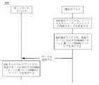
図2は、この出願の実施形態によるDMRS送信方法の概略フローチャートである。図2に示す方法200は、上記のいずれかの通信システムに適用されてもよい。図2に示す方法は、通信デバイスにより実行されてもよく、通信デバイスは、ネットワークデバイス又は端末デバイスでもよく、ネットワークデバイスは、上記のいずれかのネットワークデバイスでもよく、端末デバイスは、上記のいずれかの端末デバイスでもよく、この出願のこの実施形態はそのことに限定されない。具体的には、図2に示す方法200は、以下のステップを含む。 FIG. 2 is a schematic flowchart of a DMRS transmission method according to an embodiment of this application. The
210.通信デバイスは、リソーススケジューリングユニットの現在のモードを決定し、現在のモードは、周波数ホッピングモード又は集約モードであり、周波数ホッピングモードは、1つのリソーススケジューリングユニット内のいくつかのシンボルが第1の周波数帯域に位置し、いくつかの他のシンボルが第2の周波数帯域に位置することを示し、集約モードは、複数のリソーススケジューリングユニットの集約送信を示す。 210. The communication device determines the current mode of the resource scheduling unit, the current mode is frequency hopping mode or aggregation mode, and the frequency hopping mode has several symbols in one resource scheduling unit first. It is located in the frequency band of, and some other symbols are located in the second frequency band, and the aggregation mode indicates the aggregation transmission of multiple resource scheduling units.
この出願のこの実施形態では、シンボルは、時間単位を示し、ここでのシンボルは、代替としてOFDMシンボルと呼ばれてもよく、この出願のこの実施形態はそのことに限定されないことが理解されるべきである。 In this embodiment of this application, it is understood that the symbol represents a unit of time, where the symbol may be referred to as an OFDM symbol as an alternative, and this embodiment of this application is not limited thereto. Should be.
この出願のこの実施形態での1つのリソースユニットは、n個のシンボルを含んでもよく、nは2以上の整数であることが更に理解されるべきである。例えば、nは7、14又は2〜13のいずれかの値であり、この出願のこの実施形態はそのことに限定されない。 It should be further understood that one resource unit in this embodiment of this application may contain n symbols, where n is an integer greater than or equal to 2. For example, n is a value of any of 7, 14 or 2-13, and this embodiment of this application is not limited thereto.
この出願のこの実施形態では、DMRSパターンは、代替としてDMRS分布情報又はDMRS属性と呼ばれてもよく、DMRSパターンは、DMRSにより占有されるシンボルの位置及び数量を示すことができ、この出願のこの実施形態はそのことに限定されないことが理解されるべきである。 In this embodiment of this application, the DMRS pattern may be referred to as DMRS distribution information or DMRS attributes as an alternative, and the DMRS pattern can indicate the position and quantity of symbols occupied by DMRS and of this application. It should be understood that this embodiment is not limited to that.
220.通信デバイスは、現在のモードに対応するDMRSパターンを使用することにより、DMRSマッピング又はデマッピングを実行し、現在のモードに対応するDMRSパターンにおけるDMRSにより占有されるシンボルの位置は、予め設定されたDMRSパターンにおけるDMRSにより占有されるシンボルの位置とは異なる。 220. The communication device performs DMRS mapping or demapping by using the DMRS pattern corresponding to the current mode, and the position of the symbol occupied by DMRS in the DMRS pattern corresponding to the current mode is preset. It is different from the position of the symbol occupied by DMRS in the DMRS pattern.
この出願のこの実施形態では、DMRSパターンは、DMRSにより占有されるシンボルの位置を示すことができ、DMRSパターンは、代替としてDMRS位置、DMRS属性又はデータ分布情報と呼ばれてもよく、この出願のこの実施形態はそのことに限定されないことが理解されるべきである。 In this embodiment of this application, the DMRS pattern can indicate the position of a symbol occupied by DMRS, and the DMRS pattern may be referred to as DMRS position, DMRS attribute or data distribution information as an alternative, this application. It should be understood that this embodiment of is not limited to that.
データを送信するとき、通信デバイスは、現在のモードに対応するDMRSパターンに基づいてDMRSマッピングを実行し、データを受信するとき、通信デバイスは、現在のモードに対応するDMRSパターンに基づいてDMRSデマッピングを実行することが理解されるべきである。 When sending data, the communication device performs DMRS mapping based on the DMRS pattern corresponding to the current mode, and when receiving data, the communication device performs DMRS dede based on the DMRS pattern corresponding to the current mode. It should be understood to perform the mapping.
例えば、通信デバイスはネットワークデバイスであり、アップリンク送信を実行するとき、通信デバイスは、現在のモードに対応するDMRSパターンを使用することにより、DMRSデマッピングを実行し、ダウンリンク送信を実行するとき、通信デバイスは、現在のモードに対応するDMRSパターンを使用することにより、DMRSマッピングを実行する。他の例では、通信デバイスは端末デバイスであり、アップリンク送信を実行するとき、通信デバイスは、現在のモードに対応するDMRSパターンを使用することにより、DMRSマッピングを実行し、ダウンリンク送信を実行するとき、通信デバイスは、現在のモードに対応するDMRSパターンを使用することにより、DMRSデマッピングを実行する。 For example, when the communication device is a network device and performs uplink transmission, the communication device performs DMRS demapping and performs downlink transmission by using the DMRS pattern corresponding to the current mode. , The communication device performs DMRS mapping by using the DMRS pattern corresponding to the current mode. In another example, the communication device is a terminal device, and when performing uplink transmission, the communication device performs DMRS mapping and performs downlink transmission by using the DMRS pattern corresponding to the current mode. When doing so, the communication device performs DMRS demapping by using the DMRS pattern corresponding to the current mode.
この出願のこの実施形態では、予め設定されたDMRSパターンは、代替として、所定のパターン、デフォルトパターン又は第1のDMRSパターンと呼ばれてもよく、現在のモードに対応するDMRSパターンは、代替として、第2のDMRSパターンと呼ばれてもよいことが理解されるべきである。この出願のこの実施形態では、予め設定されたDMRSパターンは、第1のモード(すなわち、非周波数ホッピング及び非集約モード)において使用されるDMRSパターンを示す。 In this embodiment of the application, the preset DMRS pattern may be referred to as a predetermined pattern, default pattern or first DMRS pattern as an alternative, and the DMRS pattern corresponding to the current mode is an alternative. It should be understood that it may be called the second DMRS pattern. In this embodiment of the application, the preset DMRS pattern refers to the DMRS pattern used in the first mode (ie, non-frequency hopping and non-aggregate modes).
従来技術では、通信は、いずれかの送信モードにおいて予め設定されたDMRSパターンを使用することにより実行される。具体的には、DMRSにより占有されるシンボルの位置は、予め設定されたDMRSパターンにおけるDMRSにより占有されるシンボルの位置と同じである。しかし、いくつかの適用シナリオでは、リソーススケジューリングユニットのモードが変更されたとき、DMRSが依然としてDMRSを常に送信する既存の方式で送信される場合、予め設定されたDMRSパターンにおけるDMRSの分布方式は、異なるモードの要件を満たすのに困難であるので、DMRSリソースの浪費又は受信端の劣った復調性能のような悪影響が引き起こされる。その結果、ネットワーク性能が影響を受ける。 In the prior art, communication is performed by using a preset DMRS pattern in either transmission mode. Specifically, the position of the symbol occupied by DMRS is the same as the position of the symbol occupied by DMRS in the preset DMRS pattern. However, in some application scenarios, when the mode of the resource scheduling unit is changed, if DMRS is still sent in the existing way that always sends DMRS, then the distribution method of DMRS in the preset DMRS pattern is Difficulty in meeting the requirements of different modes causes adverse effects such as wasted DMRS resources or poor demodulation performance at the receiving end. As a result, network performance is affected.
しかし、この出願のこの実施形態での異なるモードにおけるDMRSパターンは、予め設定されたパターンとは異なり、DMRSにより占有されるシンボルの位置は、この出願のこの実施形態では、異なるモードに基づいて柔軟に選択できる。したがって、この出願のこの実施形態では、異なるモードの要件が満たされることができ、それにより、ネットワーク性能を改善する。 However, the DMRS pattern in different modes in this embodiment of this application is different from the preset pattern, and the position of the symbols occupied by DMRS is flexible in this embodiment of this application based on the different modes. Can be selected. Therefore, in this embodiment of this application, the requirements of different modes can be met, thereby improving network performance.
この出願の実施形態によるDMRS送信方法の具体的な例について、図3及び図4をそれぞれ参照して以下に説明する。 Specific examples of the DMRS transmission method according to the embodiment of this application will be described below with reference to FIGS. 3 and 4, respectively.
図3は、この出願の実施形態によるDMRS送信方法を示し、図3は、この出願のこの実施形態によるダウンリンク送信中のDMRS送信方法を記載する。具体的には、図3に示すように、当該方法300は、以下のステップを含む。 FIG. 3 shows a DMRS transmission method according to an embodiment of this application, and FIG. 3 describes a DMRS transmission method during downlink transmission according to this embodiment of this application. Specifically, as shown in FIG. 3, the
310.ネットワークデバイスは、リソーススケジューリングユニットの現在のモードを決定する。 310. The network device determines the current mode of the resource scheduling unit.
具体的には、ネットワークデバイスは、複数の方式で現在のモードを決定してもよい。 Specifically, the network device may determine the current mode in a plurality of ways.
任意選択で、実現方式では、ネットワークデバイスは、端末デバイスにより報告されたチャネル状態情報及びセルのネットワーク状態に基づいて現在のモードを決定してもよい。 Optionally, in the implementation scheme, the network device may determine the current mode based on the channel state information reported by the terminal device and the network state of the cell.
任意選択で、ネットワークデバイスは、端末デバイスにより使用される波形、例えば、シングルキャリア波形又はマルチキャリア波形に基づいて現在のモードを決定してもよい。例えば、端末デバイスがシングルキャリア波形を使用するとき、現在のモードは周波数ホッピングモードでもよく、端末デバイスがマルチキャリア波形を使用するとき、現在のモードは集約モードでもよい。この出願のこの実施形態はそのことに限定されない。例えば、端末デバイスがシングルキャリア波形を使用するとき、現在のモードは、代替として、集約モードでもよい。 Optionally, the network device may determine the current mode based on the waveform used by the terminal device, such as a single carrier waveform or a multicarrier waveform. For example, when the terminal device uses a single carrier waveform, the current mode may be frequency hopping mode, and when the terminal device uses a multicarrier waveform, the current mode may be aggregate mode. This embodiment of this application is not limited to that. For example, when the terminal device uses a single carrier waveform, the current mode may be an aggregate mode as an alternative.
任意選択で、他の実現方式では、ネットワークデバイスは、サービスタイプに基づいて現在のモードを決定してもよい。サービスタイプは、迅速な復調を要求するサービス、高送信性能を要求するサービス等を含んでもよい。 Optionally, in other implementations, the network device may determine the current mode based on the service type. The service type may include a service that requires rapid demodulation, a service that requires high transmission performance, and the like.
任意選択で、他の実現方式では、ネットワークデバイスは、端末デバイスにより送信された指示情報に基づいて現在のモードを決定してもよい。具体的には、端末デバイスは、ネットワーク状態又はサービス状態のような現在の状態に基づいて現在のモードを決定してもよく、次いで、端末デバイスは、現在のモードをネットワークデバイスに示す。この場合、端末デバイスは、指示情報をネットワークデバイスに送信し、それにより、ネットワークデバイスは、端末デバイスにより送信された指示情報に基づいて現在のモードを決定する。 Optionally, in other implementations, the network device may determine the current mode based on the instructional information transmitted by the terminal device. Specifically, the terminal device may determine the current mode based on the current state, such as network state or service state, and then the terminal device indicates the current mode to the network device. In this case, the terminal device sends the instruction information to the network device, whereby the network device determines the current mode based on the instruction information transmitted by the terminal device.
320.ネットワークデバイスは、現在のモードに対応するDMRSパターンに基づいてDMRSマッピングを実行する。 320. The network device performs DMRS mapping based on the DMRS pattern corresponding to the current mode.
具体的には、ネットワークデバイスは、DMRSパターンに基づいてDMRS及びデータをマッピングし、マッピングされたDMRS及びデータを送信する。 Specifically, the network device maps DMRS and data based on the DMRS pattern and transmits the mapped DMRS and data.
実現方式では、現在のモードに対応するDMRSパターンは、システムにより予め設定されてもよい。具体的には、システムは、リソーススケジューリングユニットのモードとDMRSパターンとの間の対応関係を予め設定してもよく、現在のモードを決定した後に、ネットワークデバイス及び端末デバイスは、予め設定された対応関係に基づいて、現在のモードに対応するDMRSパターンを決定してもよい。 In the implementation method, the DMRS pattern corresponding to the current mode may be preset by the system. Specifically, the system may preset the correspondence between the mode of the resource scheduling unit and the DMRS pattern, and after determining the current mode, the network device and the terminal device have a preset correspondence. Based on the relationship, the DMRS pattern corresponding to the current mode may be determined.
他の実現方式では、ネットワークデバイスは、現在のモードに基づいて対応するDMRSパターンを決定し、第2の指示情報を使用することにより、現在のモードに対応するDMRSパターンを端末デバイスに示してもよい。例えば、ネットワークデバイスは、現在のモードに対応するチャネル状態、現在のモードに対応するサービス要件等に基づいて、現在のモードに対応するDMRSパターンを柔軟に決定してもよく、この出願のこの実施形態はそのことに限定されない。 In other implementations, the network device may determine the corresponding DMRS pattern based on the current mode and use the second instruction information to indicate to the terminal device the DMRS pattern corresponding to the current mode. good. For example, the network device may flexibly determine the DMRS pattern corresponding to the current mode based on the channel state corresponding to the current mode, the service requirements corresponding to the current mode, etc., and this implementation of this application. The form is not limited to that.
330.端末デバイスは、現在のモードに対応するDMRSパターンに基づいてDMRSデマッピングを実行する。 330. The terminal device performs DMRS demapping based on the DMRS pattern corresponding to the current mode.
ネットワークデバイスにより送信されたデータを受信した後に、端末デバイスは、現在のモードに対応するDMRSパターンに基づいてDMRSデマッピングを実行し、DMRSに基づいてデータを復調してもよい。 After receiving the data transmitted by the network device, the terminal device may perform DMRS demapping based on the DMRS pattern corresponding to the current mode and demodulate the data based on DMRS.
DMRSデマッピングを実行する前に、端末デバイスは、ネットワークデバイスによりDMRSマッピングに使用されるDMRSパターン、すなわち、現在のモードに対応するDMRSパターンを習得する必要があることが理解されるべきである。 Before performing DMRS demapping, it should be understood that the terminal device needs to learn the DMRS pattern used by the network device for DMRS mapping, that is, the DMRS pattern corresponding to the current mode.
実現方式では、現在のモードに対応するDMRSパターンは、システムにより予め設定されてもよい。具体的には、システムは、リソーススケジューリングユニットのモードとDMRSパターンとの間の対応関係を予め設定してもよく、リソーススケジューリングユニットのモードを決定したとき、端末デバイスは、予め設定された対応関係に基づいて、現在のモードに対応するDMRSパターンを決定してもよい。具体的には、端末デバイスは、複数の方式で現在のモードを決定してもよい。 In the implementation method, the DMRS pattern corresponding to the current mode may be preset by the system. Specifically, the system may preset the correspondence between the mode of the resource scheduling unit and the DMRS pattern, and when the mode of the resource scheduling unit is determined, the terminal device has a preset correspondence. The DMRS pattern corresponding to the current mode may be determined based on. Specifically, the terminal device may determine the current mode in a plurality of ways.
任意選択で、端末デバイスは、ネットワークデバイスの指示に基づいて現在のモードを決定してもよい。具体的には、端末デバイスは、ネットワークデバイスにより送信された第1の指示情報を受信してもよく、第1の指示情報は、現在のモードを決定するために端末デバイスにより使用される。第1の指示情報を取得した後に、端末デバイスは、第1の指示情報に従ってリソーススケジューリングユニットの現在のモードを決定してもよい。 Optionally, the terminal device may determine the current mode based on the instructions of the network device. Specifically, the terminal device may receive the first instruction information transmitted by the network device, which is used by the terminal device to determine the current mode. After acquiring the first instruction information, the terminal device may determine the current mode of the resource scheduling unit according to the first instruction information.
第1の指示情報は、現在のモードが集約モード又は周波数ホッピングモードであることを直接的に示してもよいことが理解されるべきである。任意選択で、第1の指示情報は、現在のモードを間接的に示してもよい。例えば、第1の指示情報は、リソーススケジューリングユニットの長さを示し、端末デバイスは、リソーススケジューリングユニットの長さに基づいて現在のモードを決定してもよい。他の例では、第1の指示情報は、現在のサービスタイプを示し、端末デバイスは、サービスタイプに基づいて現在のモードを決定し、この出願のこの実施形態はそのことに限定されない。 It should be understood that the first instructional information may directly indicate that the current mode is an aggregate mode or a frequency hopping mode. Optionally, the first instructional information may indirectly indicate the current mode. For example, the first instructional information indicates the length of the resource scheduling unit, and the terminal device may determine the current mode based on the length of the resource scheduling unit. In another example, the first instructional information indicates the current service type, the terminal device determines the current mode based on the service type, and this embodiment of the application is not limited thereto.
ネットワークデバイスは、ダウンリンク制御情報(downlink control information, DCI)、無線リソース制御(radio resource control, RRC)シグナリング及び媒体アクセス制御(media access control, MAC)制御エレメント(control element, CE)のような複数のタイプのシグナリングを使用することにより、第1の指示情報を端末デバイスに送信してもよいことが理解されるべきである。これはこの出願のこの実施形態では限定されない。 Network devices include multiple downlink control information (DCI), radio resource control (RRC) signaling and media access control (MAC) control elements (CE). It should be understood that the first instructional information may be transmitted to the terminal device by using the type of signaling of. This is not limited to this embodiment of this application.
任意選択で、端末デバイスは、現在の状態に基づいて現在のモードを決定してもよい。例えば、端末デバイスは、ネットワーク状態又はサービス状態に基づいて現在のモードを決定し、次いで、端末デバイスは、現在のモードをネットワークデバイスに示す。 Optionally, the terminal device may determine the current mode based on the current state. For example, the terminal device determines the current mode based on the network state or service state, and then the terminal device indicates the current mode to the network device.
代替として、DMRSパターンを決定する他の実現方式では、端末デバイスは、ネットワークデバイスにより送信された第2の指示情報に基づいて、現在のモードに対応するDMRSパターンを決定する。 Alternatively, in another implementation of determining the DMRS pattern, the terminal device determines the DMRS pattern corresponding to the current mode based on the second instructional information transmitted by the network device.
ネットワークデバイスは、DCI、RRCシグナリング及びMAC CEのような複数のタイプのシグナリングを使用することにより、第2の指示情報を端末デバイスに送信してもよいことが理解されるべきである。これはこの出願のこの実施形態では限定されない。 It should be understood that the network device may send a second instructional information to the terminal device by using multiple types of signaling such as DCI, RRC signaling and MAC CE. This is not limited to this embodiment of this application.
具体的には、ネットワークデバイスは、ネットワークデバイスが端末デバイスとデータ送信を実行するときにDMRSパターンを決定する必要があるので、ネットワークデバイスは、ネットワークデバイスが端末デバイスとデータ送信を実行するときに使用されるDMRSパターンを端末デバイスに通知し、端末デバイスは、DMRSパターンに基づいてDMRSの時間周波数リソース位置を決定してもよく、次いで、DMRSマッピング又はデマッピングを実行してもよい。 Specifically, the network device needs to determine the DMRS pattern when the network device performs data transmission with the terminal device, so the network device is used when the network device performs data transmission with the terminal device. The DMRS pattern to be generated may be notified to the terminal device, and the terminal device may determine the time frequency resource position of DMRS based on the DMRS pattern, and then perform DMRS mapping or demapping.
図4は、この出願の実施形態によるDMRS送信方法を示し、図4は、この出願のこの実施形態によるアップリンク送信中のDMRS送信方法を記載する。具体的には、図4に示すように、当該方法400は、以下のステップを含む。 FIG. 4 shows a DMRS transmission method according to an embodiment of this application, and FIG. 4 describes a DMRS transmission method during uplink transmission according to this embodiment of this application. Specifically, as shown in FIG. 4, the
410.端末デバイスは、リソーススケジューリングユニットの現在のモードを決定する。 410. The terminal device determines the current mode of the resource scheduling unit.
ステップ410は、図3のステップ330において端末デバイスが現在のモードを決定する方式と同様であることが理解されるべきである。繰り返しを避けるために、詳細な説明はここでは適宜省略する。 It should be understood that step 410 is similar to the method by which the terminal device determines the current mode in step 330 of FIG. In order to avoid repetition, detailed description will be omitted here as appropriate.
任意選択で、端末デバイスは、ネットワークデバイスの指示に基づいて現在のモードを決定してもよい。具体的には、端末デバイスは、ネットワークデバイスにより送信された第1の指示情報を受信してもよく、第1の指示情報は、現在のモードを決定するために端末デバイスにより使用される。第1の指示情報を取得した後に、端末デバイスは、第1の指示情報に従ってリソーススケジューリングユニットの現在のモードを決定してもよい。 Optionally, the terminal device may determine the current mode based on the instructions of the network device. Specifically, the terminal device may receive the first instruction information transmitted by the network device, which is used by the terminal device to determine the current mode. After acquiring the first instruction information, the terminal device may determine the current mode of the resource scheduling unit according to the first instruction information.
第1の指示情報は、現在のモードが集約モード又は周波数ホッピングモードであることを直接的に示してもよいことが理解されるべきである。任意選択で、第1の指示情報は、現在のモードを間接的に示してもよい。例えば、第1の指示情報は、リソーススケジューリングユニットの長さを示し、端末デバイスは、リソーススケジューリングユニットの長さに基づいて現在のモードを決定してもよい。他の例では、第1の指示情報は、現在のサービスタイプを示し、端末デバイスは、サービスタイプに基づいて現在のモードを決定し、この出願のこの実施形態はそのことに限定されない。 It should be understood that the first instructional information may directly indicate that the current mode is an aggregate mode or a frequency hopping mode. Optionally, the first instructional information may indirectly indicate the current mode. For example, the first instructional information indicates the length of the resource scheduling unit, and the terminal device may determine the current mode based on the length of the resource scheduling unit. In another example, the first instructional information indicates the current service type, the terminal device determines the current mode based on the service type, and this embodiment of the application is not limited thereto.
ネットワークデバイスは、ダウンリンク制御情報(downlink control information, DCI)、無線リソース制御(radio resource control, RRC)シグナリング及び媒体アクセス制御(media access control, MAC)制御エレメント(control element, CE)のような複数のタイプのシグナリングを使用することにより、第1の指示情報を端末デバイスに送信してもよいことが理解されるべきである。これはこの出願のこの実施形態では限定されない。 Network devices include multiple downlink control information (DCI), radio resource control (RRC) signaling and media access control (MAC) control elements (CE). It should be understood that the first instructional information may be transmitted to the terminal device by using the type of signaling of. This is not limited to this embodiment of this application.
任意選択で、端末デバイスは、現在の状態に基づいて現在のモードを決定してもよい。例えば、端末デバイスは、ネットワーク状態又はサービス状態に基づいて現在のモードを決定し、次いで、端末デバイスは、現在のモードをネットワークデバイスに示す。 Optionally, the terminal device may determine the current mode based on the current state. For example, the terminal device determines the current mode based on the network state or service state, and then the terminal device indicates the current mode to the network device.
420.端末デバイスは、現在のモードに対応するDMRSパターンに基づいてDMRSマッピングを実行する。 420. The terminal device performs DMRS mapping based on the DMRS pattern corresponding to the current mode.
具体的には、端末デバイスは、最初に現在のモードに対応するDMRSパターンを決定し、DMRSパターンに基づいてDMRS及びデータをマッピングし、マッピングされたDMRS及びデータを送信する。 Specifically, the terminal device first determines the DMRS pattern corresponding to the current mode, maps the DMRS and data based on the DMRS pattern, and transmits the mapped DMRS and data.
具体的には、ステップ420において端末デバイスにより現在のモードに対応するDMRSパターンを決定するための方法は、図3のステップ330において端末デバイスにより現在のモードに対応するDMRSパターンを決定するための方法に対応する。繰り返しを避けるために、詳細な説明はここでは適宜省略する。 Specifically, the method for determining the DMRS pattern corresponding to the current mode by the terminal device in step 420 is the method for determining the DMRS pattern corresponding to the current mode by the terminal device in step 330 of FIG. Corresponds to. In order to avoid repetition, detailed description will be omitted here as appropriate.
実現方式では、現在のモードに対応するDMRSパターンは、システムにより予め設定されてもよい。具体的には、システムは、リソーススケジューリングユニットのモードとDMRSパターンとの間の対応関係を予め設定してもよく、リソーススケジューリングユニットのモードを決定したとき、端末デバイスは、予め設定された対応関係に基づいて、現在のモードに対応するDMRSパターンを決定してもよい。具体的には、端末デバイスは、複数の方式で現在のモードを決定してもよい。 In the implementation method, the DMRS pattern corresponding to the current mode may be preset by the system. Specifically, the system may preset the correspondence between the mode of the resource scheduling unit and the DMRS pattern, and when the mode of the resource scheduling unit is determined, the terminal device has a preset correspondence. The DMRS pattern corresponding to the current mode may be determined based on. Specifically, the terminal device may determine the current mode in a plurality of ways.
代替として、DMRSパターンを決定する他の実現方式では、端末デバイスは、ネットワークデバイスにより送信された第2の指示情報に基づいて、現在のモードに対応するDMRSパターンを決定する。 Alternatively, in another implementation of determining the DMRS pattern, the terminal device determines the DMRS pattern corresponding to the current mode based on the second instructional information transmitted by the network device.
ネットワークデバイスは、DCI、RRCシグナリング及びMAC CEのような複数のタイプのシグナリングを使用することにより、第2の指示情報を端末デバイスに送信してもよいことが理解されるべきである。これはこの出願のこの実施形態では限定されない。 It should be understood that the network device may send a second instructional information to the terminal device by using multiple types of signaling such as DCI, RRC signaling and MAC CE. This is not limited to this embodiment of this application.
具体的には、ネットワークデバイスは、ネットワークデバイスが端末デバイスとデータ送信を実行するときにDMRSパターンを決定する必要があるので、ネットワークデバイスは、ネットワークデバイスが端末デバイスとデータ送信を実行するときに使用されるDMRSパターンを端末デバイスに通知し、端末デバイスは、DMRSパターンに基づいてDMRSの時間周波数リソース位置を決定してもよく、次いで、DMRSマッピング又はデマッピングを実行してもよい。 Specifically, the network device needs to determine the DMRS pattern when the network device performs data transmission with the terminal device, so the network device is used when the network device performs data transmission with the terminal device. The DMRS pattern to be generated may be notified to the terminal device, and the terminal device may determine the time frequency resource position of DMRS based on the DMRS pattern, and then perform DMRS mapping or demapping.
430.ネットワークデバイスは、現在のモードに対応するDMRSパターンに基づいてDMRSデマッピングを実行する。 430. The network device performs DMRS demapping based on the DMRS pattern corresponding to the current mode.
端末デバイスにより送信されたデータを受信した後に、ネットワークデバイスは、現在のモードに対応するDMRSパターンに基づいてDMRSデマッピングを実行し、DMRSに基づいてデータを復調してもよい。 After receiving the data transmitted by the terminal device, the network device may perform DMRS demapping based on the DMRS pattern corresponding to the current mode and demodulate the data based on DMRS.
DMRSデマッピングを実行する前に、ネットワークデバイスは、端末デバイスによりDMRSマッピングに使用されるDMRSパターン、すなわち、現在のモードに対応するDMRSパターンを習得する必要があることが理解されるべきである。 Before performing DMRS demapping, it should be understood that network devices need to learn the DMRS pattern used by terminal devices for DMRS mapping, that is, the DMRS pattern corresponding to the current mode.
ステップ430においてネットワークデバイスにより現在のモードに対応するパターンを決定するための方法は、図3のステップ320においてネットワークデバイスにより現在のモードに対応するパターンを決定するための方法に対応することが理解されるべきである。繰り返しを避けるために、詳細な説明はここでは適宜省略する。 It is understood that the method for determining the pattern corresponding to the current mode by the network device in step 430 corresponds to the method for determining the pattern corresponding to the current mode by the network device in step 320 of FIG. Should be. In order to avoid repetition, detailed description will be omitted here as appropriate.
実現方式では、現在のモードに対応するDMRSパターンは、システムにより予め設定されてもよい。具体的には、システムは、リソーススケジューリングユニットのモードとDMRSパターンとの間の対応関係を予め設定してもよく、現在のモードを決定した後に、ネットワークデバイス及び端末デバイスは、予め設定された対応関係に基づいて、現在のモードに対応するDMRSパターンを決定してもよい。 In the implementation method, the DMRS pattern corresponding to the current mode may be preset by the system. Specifically, the system may preset the correspondence between the mode of the resource scheduling unit and the DMRS pattern, and after determining the current mode, the network device and the terminal device have a preset correspondence. Based on the relationship, the DMRS pattern corresponding to the current mode may be determined.
他の実現方式では、ネットワークデバイスは、現在のモードに基づいて対応するDMRSパターンを決定し、第2の指示情報を使用することにより、現在のモードに対応するDMRSパターンを端末デバイスに示してもよい。例えば、ネットワークデバイスは、現在のモードに対応するチャネル状態、現在のモードに対応するサービス要件等に基づいて、現在のモードに対応するDMRSパターンを柔軟に決定してもよく、この出願のこの実施形態はそのことに限定されない。 In other implementations, the network device may determine the corresponding DMRS pattern based on the current mode and use the second instruction information to indicate to the terminal device the DMRS pattern corresponding to the current mode. good. For example, the network device may flexibly determine the DMRS pattern corresponding to the current mode based on the channel state corresponding to the current mode, the service requirements corresponding to the current mode, etc., and this implementation of this application. The form is not limited to that.
具体的には、ネットワークデバイスは、複数の方式で現在のモードを決定してもよい。 Specifically, the network device may determine the current mode in a plurality of ways.
任意選択で、実現方式では、ネットワークデバイスは、端末デバイスにより報告されたチャネル状態情報及びセルのネットワーク状態に基づいて現在のモードを決定してもよい。 Optionally, in the implementation scheme, the network device may determine the current mode based on the channel state information reported by the terminal device and the network state of the cell.
任意選択で、ネットワークデバイスは、端末デバイスにより使用される波形、例えば、シングルキャリア波形又はマルチキャリア波形に基づいて現在のモードを決定してもよい。例えば、端末デバイスがシングルキャリア波形を使用するとき、現在のモードは周波数ホッピングモードでもよく、端末デバイスがマルチキャリア波形を使用するとき、現在のモードは集約モードでもよい。この出願のこの実施形態はそのことに限定されない。例えば、端末デバイスがシングルキャリア波形を使用するとき、現在のモードは、代替として、集約モードでもよい。 Optionally, the network device may determine the current mode based on the waveform used by the terminal device, such as a single carrier waveform or a multicarrier waveform. For example, when the terminal device uses a single carrier waveform, the current mode may be frequency hopping mode, and when the terminal device uses a multicarrier waveform, the current mode may be aggregate mode. This embodiment of this application is not limited to that. For example, when the terminal device uses a single carrier waveform, the current mode may be an aggregate mode as an alternative.
任意選択で、他の実現方式では、ネットワークデバイスは、サービスタイプに基づいて現在のモードを決定してもよい。サービスタイプは、迅速な復調を要求するサービス、高送信性能を要求するサービス等を含んでもよい。 Optionally, in other implementations, the network device may determine the current mode based on the service type. The service type may include a service that requires rapid demodulation, a service that requires high transmission performance, and the like.
任意選択で、他の実現方式では、ネットワークデバイスは、端末デバイスにより送信された指示情報に基づいて現在のモードを決定してもよい。具体的には、端末デバイスは、ネットワーク状態又はサービス状態のような現在の状態に基づいて現在のモードを決定してもよく、次いで、端末デバイスは、現在のモードをネットワークデバイスに示す。この場合、端末デバイスは、指示情報をネットワークデバイスに送信し、それにより、ネットワークデバイスは、端末デバイスにより送信された指示情報に基づいて現在のモードを決定する。 Optionally, in other implementations, the network device may determine the current mode based on the instructional information transmitted by the terminal device. Specifically, the terminal device may determine the current mode based on the current state, such as network state or service state, and then the terminal device indicates the current mode to the network device. In this case, the terminal device sends the instruction information to the network device, whereby the network device determines the current mode based on the instruction information transmitted by the terminal device.
この出願のこの実施形態におけるアップリンク/ダウンリンク送信中のDMRS送信の具体的な形式について上述し、この出願の実施形態におけるDMRSパターンの具体的な形式について添付図面を参照して以下に詳細に説明する。 The specific form of DMRS transmission during uplink / downlink transmission in this embodiment of this application has been described above, and the specific form of DMRS pattern in embodiments of this application has been described in detail below with reference to the accompanying drawings. explain.
具体的には、予め設定されたDMRSパターンは、複数の状況を含んでもよく、例を使用することにより、詳細な説明が以下に行われる。 Specifically, the preset DMRS pattern may include a plurality of situations, and a detailed description will be given below by using an example.
状況1:予め設定されたパターンは、前方部分パターン(front-loaded pattern)である。図5に示すように、1つのリソーススケジューリングユニットが14個のシンボルを占有する例が使用され、DMRSは、1つのリソーススケジューリングユニット内でN個の連続シンボルを占有し、Nは1以上の整数である。図5は、N=1である場合を示す。N個の連続シンボルは、代替として、1つのグループのシンボルと呼ばれてもよく、1つのグループのシンボルは、少なくとも1つ(N個)の連続シンボルを含み、この出願のこの実施形態はそのことに限定されないことが理解されるべきである。 Situation 1: The preset pattern is the front-loaded pattern. As shown in FIG. 5, an example is used in which one resource scheduling unit occupies 14 symbols, DMRS occupies N consecutive symbols in one resource scheduling unit, and N is an integer greater than or equal to 1. Is. FIG. 5 shows a case where N = 1. The N contiguous symbols may, by alternative, be referred to as a group of symbols, the group of symbols containing at least one (N) contiguous symbols, wherein this embodiment of this application is such. It should be understood that it is not limited to.
状況2:予め設定されたパターンは、追加パターン(additional pattern)である。図6に示すように、1つのリソーススケジューリングユニットが14個のシンボルを占有する例が使用され、DMRSは、L個のグループのシンボルを占有し、Lは2以上の整数であり、L個のグループのシンボルは互いに隣接せず、L個のグループのシンボルのそれぞれは、少なくとも1つの連続シンボルを含む。図6では、L=2である例が使用される。具体的には、DMRSは、1つのリソーススケジューリングユニット内でM個の連続シンボル及びK個の連続シンボルを占有し、M個のシンボルはK個のシンボルに隣接せず、M及びKは1以上の整数である。図6は、M=1且つK=1である状況を示すが、本発明のこの実施形態はそのことに限定されない。例えば、M及びKは、さらに、2、3等に等しくてもよい。任意選択で、この出願のこの実施形態は、DMRSが2つのグループのシンボルを占有する場合に限定されず、Lは、代替として3に等しくてもよい。具体的には、DMRSは、周波数ホッピングなしで1つのリソーススケジューリングユニット内のP個の連続シンボルを更に占有する。任意選択で、Lは、さらに、4、5等に等しくてもよい。 Situation 2: The preset pattern is an additional pattern. As shown in FIG. 6, an example is used in which one resource scheduling unit occupies 14 symbols, DMRS occupies the symbols of L groups, L is an integer of 2 or more, and L The group symbols are not adjacent to each other, and each of the L group symbols contains at least one contiguous symbol. In FIG. 6, an example in which L = 2 is used. Specifically, DMRS occupies M consecutive symbols and K consecutive symbols in one resource scheduling unit, M symbols are not adjacent to K symbols, and M and K are 1 or more. Is an integer of. FIG. 6 shows a situation where M = 1 and K = 1, but this embodiment of the present invention is not limited thereto. For example, M and K may further be equal to 2, 3 and so on. Optionally, this embodiment of this application is not limited to the case where DMRS occupies two groups of symbols, where L may be equal to 3 as an alternative. Specifically, DMRS further occupies P consecutive symbols in a resource scheduling unit without frequency hopping. Optionally, L may further be equal to 4, 5, etc.
状況1ではDMRSが1つのグループのシンボルのみを占有し、状況2ではDMRSが少なくとも2つのグループのシンボルを占有し、状況1及び状況2は異なる適用シナリオに対応してもよいことが理解されるべきである。状況2は、チャネル状態が比較的大きく変動するシナリオ、例えば、端末デバイスが急速に移動するシナリオに対応してもよく、状況2では、データは、複数のグループのDMRSを送信することにより正確に復調される。しかし、状況1は、チャネル状態が比較的安定しているシナリオに対応してもよく、したがって、データは、1つのグループのDMRSを送信することにより正確に復調され得る。 It is understood that in
現在のモードが周波数ホッピングモード又は集約モードであるとき、この出願のこの実施形態の現在のモードに対応するDMRSパターンについて、それぞれ上記の2つの状況を参照して、以下に詳細に説明する。 When the current mode is frequency hopping mode or aggregation mode, the DMRS pattern corresponding to the current mode of this embodiment of this application will be described in detail below with reference to each of the above two situations.
現在のモードが周波数ホッピングモードであるとき、状態1及び状態2に対応するこの出願のこの実施形態のパターンについて最初に説明する。 The pattern of this embodiment of this application corresponding to
具体的には、現在のモードが周波数ホッピングモードであるとき、上記の状況1について、この出願のこの実施形態では、図7に示すように、現在のモードに対応するDMRSパターンにおけるDMRSは、第1の周波数帯域内のN1個の連続シンボル及び第2の周波数帯域内のN2個の連続シンボルを占有し、N1は1以上の整数であり、N2は1以上の整数である。図7は、N1=1且つN2=1である場合を示す。Specifically, when the current mode is the frequency hopping mode, for
図8は、DMRSが依然として周波数ホッピングモードにおいて図5に示す予め設定されたパターンにおける位置に基づいて送信される既存の方式を示す。図8から、DMRSが第1の周波数帯域で送信され、DMRSは第2の周波数帯域では送信されないことが習得され得る。しかし、実際の適用の中で、第2の周波数帯域に対応するチャネル状態は、通常では、第1の周波数帯域に対応するチャネル状態とは異なる。したがって、データが第1の周波数帯域で送信されたDMRSのみに基づいて復調された場合、第2の周波数帯域でのデータ復調の精度が影響を受け、ネットワーク性能が影響を受ける。 FIG. 8 shows an existing method in which DMRS is still transmitted in frequency hopping mode based on position in the preset pattern shown in FIG. From FIG. 8, it can be learned that DMRS is transmitted in the first frequency band and DMRS is not transmitted in the second frequency band. However, in practical applications, the channel state corresponding to the second frequency band is usually different from the channel state corresponding to the first frequency band. Therefore, if the data is demodulated based solely on the DMRS transmitted in the first frequency band, the accuracy of the data demodulation in the second frequency band will be affected and the network performance will be affected.
しかし、この出願のこの実施形態では、周波数ホッピングモードにおいて、2つの周波数帯域のチャネル状態は異なる。したがって、この出願のこの実施形態では、DMRSは各周波数帯域で送信され、それにより、受信端デバイスは、周波数帯域内のDMRSに基づいて対応するデータを復調でき、それにより、データ復調精度を改善し、復調性能を改善する。However, in this embodiment of this application, in the frequency hopping mode, the channel states of the two frequency bands are different. Therefore, in this embodiment of this application, the DMRS is transmitted in each frequency band, whereby the receiving enddevice can demodulate the corresponding data based on the DMRS in the frequency band, thereby improving the data demodulation accuracy. And improve the demodulation performance.
N2個のシンボルの位置は、第2の周波数帯域内のいずれかの位置でもよく、この出願のこの実施形態はそのことに限定されないことが理解されるべきである。It should be understood that the position of the Ntwo symbols may be any position within the second frequency band and this embodiment of this application is not limited to that.
任意選択で、実施形態では、N1=N2であり、第1の周波数帯域内のN1個のシンボルの位置は、第2の周波数帯域内のN2個のシンボルの位置と対称的である。例えば、図9に示すように、N1=N2=1であり、N1個のシンボルの位置及びN2個のシンボルの位置は、それぞれ、第1の周波数帯域内の第3シンボルの位置及び第2の周波数帯域内の第3シンボルの位置である。Optionally, in the embodiment, N1 = N2 , and the position of the N1 symbol in the first frequency band is symmetrical with the positionof the N 2 symbols in the second frequency band. be. For example, as shown in FIG. 9, N1 = N2 = 1, andthe position of the N 1 symbol and the position of the N2 symbols are the positions of the third symbol in the first frequency band, respectively. And the position of the third symbol in the second frequency band.
したがって、この出願のこの実施形態では、2つの周波数帯域内のDMRSは対称的に配置され、それにより、受信端デバイスは、同じ方式で2つの周波数帯域でデータ復調を実行でき、それにより、復調の複雑さを低減し、ネットワーク性能を改善する。 Therefore, in this embodiment of this application, DMRSs within the two frequency bands are symmetrically arranged so that the receiving end device can perform data demodulation in the two frequency bands in the same manner, thereby demodulating. Reduces complexity and improves network performance.
任意選択で、他の実施形態では、N1=N2=1又は2である。Optionally, in other embodiments, N1 = N2 = 1 or 2.
任意選択で、N1個のシンボルは、第1の周波数帯域内の第1の領域内の第1シンボルを含み、第1の領域は、データ及びDMRSにより占有されるシンボルを含む。Optionally, the N1 symbol contains the first symbol in the first region within the first frequency band, and the first region contains the symbols occupied by the data and DMRS.
任意選択で、N2個のシンボルは、第2の周波数帯域内の第1シンボルを含む。Optionally, the N2 symbols include the first symbol in the second frequency band.
任意選択で、他の実施形態では、N2個のシンボルは、第2の周波数帯域内の第1シンボルを含む。例えば、図7に示すように、N2=1であり、DMRSは、第2の周波数帯域内の第1シンボルを占有する。図7は、N2=1である状況のみを示すが、この出願のこの実施形態はそのことに限定されないことが理解されるべきである。DMRSが第2の周波数帯域内の複数のシンボルの位置を占有するとき、複数のシンボルは、第2の周波数帯域内の第1シンボルから連続的に配置される。例えば、N2=2であるとき、DMRSは、第2の周波数帯域内の第1シンボル及び第2シンボルを占有する。Optionally, in other embodiments, the N2 symbols include the first symbol in the second frequency band. For example, as shown in FIG. 7, N2 = 1, and DMRS occupies the first symbol in the second frequency band. It should be understood that FIG. 7shows only the situation where N 2 = 1, but this embodiment of this application is not limited to that. When the DMRS occupies the positions of the plurality of symbols in the second frequency band, the plurality of symbols are arranged consecutively from the first symbol in the second frequency band. For example, when N2 = 2, DMRS occupies the first and second symbols in the second frequency band.
受信端デバイスは、受信端デバイスがDMRSを取得した後にのみデータを復調してもよい。したがって、この出願のこの実施形態では、DMRSは、第2の周波数帯域内の第1シンボルを占有するように設定され、それにより、受信端デバイスは、最初にDMRSを取得でき、次いで、データを迅速に復調できる。The receiving end device may demodulate the data only after the receiving end device has acquired the DMRS. Therefore, in this embodiment of this application, the DMRS is set to occupy the first symbol in the second frequency band, whereby the receiving enddevice can first acquire the DMRS and then the data. It can be demodulated quickly.
N2個のシンボルの位置は、さらに、第2の周波数帯域内のいずれかの位置でもよく、この出願のこの実施形態はそのことに限定されないことが理解されるべきである。It should be understood that the position of the Ntwo symbols may further be any position within the second frequency band, and this embodiment of this application is not limited thereto.
例えば、N2個のシンボルの位置は、第2の周波数帯域の前半部分にあるか、或いはN2個のシンボルのうち第1シンボルは、第2の周波数帯域の前半部分に位置する。例えば、N2=2であり、2つのシンボルは、第2の周波数帯域内の第2シンボル及び第3シンボル又は第3シンボル及び第4シンボルでもよく、この出願のこの実施形態はそのことに限定されない。For example,the position of the N 2 symbols is in the first half of the second frequency band, or the first of the N2 symbols is in the first half of the second frequency band. For example, N2 = 2, and the two symbols may be the second and third symbols or the third and fourth symbols in the second frequency band, and this embodiment of this application is limited thereto. Not done.
現在のモードが周波数ホッピングモードであるとき、上記の状況2における追加パターンの場合、この出願のこの実施形態では、図10に示すように、現在のモードに対応するDMRSパターンにおけるDMRSは、第1の周波数帯域内のシンボルのうちM1個の連続シンボル及びK1個の連続シンボルと、第2の周波数帯域内のM2個の連続シンボル及びK2個の連続シンボルとを占有し、M1個のシンボルはK1個のシンボルに隣接せず、M2個のシンボルはK2個のシンボルに隣接せず、M1、K1、M2及びK2は1以上の整数である。図10は、M1、K1、M2及びK2のそれぞれが1に等しい場合を示す。In the case of the additional pattern in
任意選択で、上記は、周波数ホッピングの前に2つのシーケンスのDMRSが存在する場合、周波数ホッピング後に前者の周波数帯域及び後者の周波数帯域のそれぞれに2つのシーケンスのDMRSが存在する場合を記載しているが、この出願のこの実施形態はそのことに限定されない。例えば、周波数ホッピングの前に1つより多くのシーケンスのDMRSが存在するという条件で、この出願のこの実施形態は、周波数ホッピング後に以下の3つの種類のタイプ2のいずれか1つでもよい。詳細については、タイプ2についての以下の説明を参照する。 Optionally, the above describes the case where there are two sequences of DMRS before frequency hopping, and the case where there are two sequences of DMRS in each of the former frequency band and the latter frequency band after frequency hopping. However, this embodiment of this application is not limited to that. For example, this embodiment of this application may be one of three types of
図11は、DMRSが依然として周波数ホッピングモードにおいて図6に示す予め設定されたパターンにおける位置に基づいて送信される既存の方式を示す。図11から、1つのグループのDMRSが、第1の周波数帯域及び第2の周波数帯域のそれぞれで送信されることが習得され得る。しかし、上記の状況2のシナリオでは、チャネル状態が比較的大きく変動するので、1つのグループのDMRSのみが1つの周波数帯域で送信される場合、正確なデータ復調を確保することは困難である。 FIG. 11 shows an existing method in which DMRS is still transmitted in frequency hopping mode based on position in the preset pattern shown in FIG. From FIG. 11, it can be learned that one group of DMRSs is transmitted in each of the first and second frequency bands. However, in the scenario of
しかし、この出願のこの実施形態では、周波数ホッピングモードにおいて、チャネル状態が比較的大きく変動するときに正確なデータ復調を確保するために、複数のグループ(L個のグループ)のDMRSが2つの周波数帯域のそれぞれで送信される。 However, in this embodiment of this application, in frequency hopping mode, multiple groups (L groups) of DMRS have two frequencies to ensure accurate data demodulation when the channel state fluctuates relatively significantly. It is transmitted in each of the bands.
図6は、予め設定された追加パターンにおいてDMRSにより占有される2つのグループのシンボルにおいて、第1のグループのシンボルがリソーススケジューリングユニットの前半部分に位置し、第2のグループのシンボルがリソーススケジューリングユニットの後半部分に位置する場合を記載していることが理解されるべきである。しかし、本発明のこの実施形態はそのことに限定されない。例えば、図6における追加パターンは、2つのグループの占有シンボルのそれぞれがリソーススケジューリングユニットの前半部分に位置し得るパターンに発展してもよい。例えば、予め設定された追加パターンにおけるDMRSは、第3シンボル及び第6シンボルを占有する。したがって、この場合、図11に示す既存の方式での周波数ホッピングモードにおけるパターンは、2つのグループのDMRSが第1の周波数帯域で送信されるパターンに発展してもよい。例えば、DMRSは、第1の周波数帯域内の第3シンボル及び第6シンボルで送信され、DMRSは、第2の周波数帯域では送信されない。この場合、DMRSが第2の周波数帯域では送信されないので、第2の周波数帯域でのデータ復調の精度が影響を受け、ネットワーク性能が影響を受ける。 In FIG. 6, among the symbols of the two groups occupied by DMRS in the preset additional pattern, the symbol of the first group is located in the first half of the resource scheduling unit, and the symbol of the second group is the resource scheduling unit. It should be understood that it describes the case located in the second half of. However, this embodiment of the present invention is not limited thereto. For example, the additional pattern in FIG. 6 may evolve into a pattern in which each of the two groups of occupied symbols can be located in the first half of the resource scheduling unit. For example, DMRS in a preset additional pattern occupies the third and sixth symbols. Therefore, in this case, the pattern in the frequency hopping mode in the existing method shown in FIG. 11 may be developed into a pattern in which two groups of DMRS are transmitted in the first frequency band. For example, DMRS is transmitted in the third and sixth symbols within the first frequency band, and DMRS is not transmitted in the second frequency band. In this case, since DMRS is not transmitted in the second frequency band, the accuracy of data demodulation in the second frequency band is affected, and the network performance is affected.
しかし、この出願のこの実施形態では、周波数ホッピングモードにおいて、2つの周波数帯域のチャネル状態は異なる。したがって、この出願のこの実施形態では、DMRSは各周波数帯域で送信され、それにより、受信端デバイスは、周波数帯域内のDMRSに基づいて対応するデータを復調でき、それにより、データ復調精度を改善し、復調性能を改善する。However, in this embodiment of this application, in the frequency hopping mode, the channel states of the two frequency bands are different. Therefore, in this embodiment of this application, the DMRS is transmitted in each frequency band, whereby the receiving enddevice can demodulate the corresponding data based on the DMRS in the frequency band, thereby improving the data demodulation accuracy. And improve the demodulation performance.
第1の周波数帯域及び第2の周波数帯域でDMRSにより占有されるシンボルの位置は、この出願のこの実施形態では限定されないことが理解されるべきである。各周波数帯域がL個のグループのDMRSを含むという条件で、これはこの出願のこの実施形態では限定されない。 It should be understood that the positions of the symbols occupied by DMRS in the first and second frequency bands are not limited in this embodiment of this application. This is not limited to this embodiment of this application, provided that each frequency band contains L groups of DMRS.
任意選択で、他の実施形態では、M1=M2であり、K1=K2であり、第1の周波数帯域内のM1個のシンボル及びK1個のシンボルの位置は、第2の周波数帯域内のM2個のシンボル及びK2個のシンボルの位置と対称的である。例えば、図12に示すように、M1=M2=1であり、K1=K2=1であり、各DMRSは、第1の周波数帯域及び第2の周波数帯域内の第3シンボル及び第6シンボルの位置を占有する。Optionally, in other embodiments, M1 = M2 and K1 = K2 , and the positions ofthe M 1 and K1 symbols in the first frequency band are second. It is symmetrical with the positionsof the M 2 and K2 symbols in the frequency band of. For example, as shown in FIG. 12, M1 = M2 = 1 and K1 = K2 = 1, and each DMRS has a first frequency band and a third symbol in the second frequency band. Occupies the position of the 6th symbol.
この出願のこの実施形態では、2つの周波数帯域内のDMRSは対称的に配置され、それにより、受信端デバイスは、同じ方式で2つの周波数帯域でデータ復調を実行でき、それにより、復調の複雑さを低減し、ネットワーク性能を改善する。 In this embodiment of the application, the DMRSs within the two frequency bands are symmetrically arranged so that the receiving end device can perform data demodulation in the two frequency bands in the same manner, thereby complicating the demodulation. Reduce bandwidth and improve network performance.
任意選択で、他の実施形態では、M2個のシンボルは、第2の周波数帯域内の第1シンボルを含む。例えば、図10に示すように、M2=1であり、M2は第2の周波数帯域内の第1シンボルに対応する。図10は、M2=1である状況のみを示すが、この出願のこの実施形態はそのことに限定されないことが理解されるべきである。DMRSが第2の周波数帯域内の複数のシンボルの位置を占有するとき、複数のシンボルは、第2の周波数帯域内の第1シンボルから連続的に配置される。例えば、M2=2であるとき、DMRSは、第2の周波数帯域内の第1シンボル及び第2シンボルを占有する。Optionally, in other embodiments, the M2 symbols include the first symbol in the second frequency band. For example, as shown in FIG. 10, M2 = 1, and M2 corresponds to the first symbol in the second frequency band. FIG. 10shows only the situation where M 2 = 1, but it should be understood that this embodiment of this application is not limited to that. When the DMRS occupies the positions of the plurality of symbols in the second frequency band, the plurality of symbols are arranged consecutively from the first symbol in the second frequency band. For example, when M2 = 2, DMRS occupies the first and second symbols in the second frequency band.
受信端は、受信端デバイスがDMRSを取得した後にのみデータを復調してもよい。したがって、この出願のこの実施形態では、DMRSは、第2の周波数帯域内の第1シンボルを占有し、それにより、受信端デバイスは、最初にDMRSを取得し、迅速な復調を実行でき、それにより、迅速なデータ復調の要件を満たす。The receiving end may demodulate the data only after the receiving end device has acquired the DMRS. Therefore, in this embodiment of this application, the DMRS occupies the first symbol in the second frequency band, which allows the receiving enddevice to first acquire the DMRS and perform rapid demodulation, which allows it. Meet the requirements for rapid data demodulation.
M2個のシンボルの位置は、さらに、第2の周波数帯域内のいずれかの位置でもよく、この出願のこの実施形態はそのことに限定されないことが理解されるべきである。It should be understood that the position of the M2 symbols may further be any position within the second frequency band, and this embodiment of this application is not limited thereto.
例えば、M2個のシンボルの位置は、第2の周波数帯域の前半部分にあるか、或いはM2個のシンボルのうち第1シンボルは、第2の周波数帯域の前半部分に位置する。例えば、M2=2であり、2つのシンボルは、第2の周波数帯域内の第2シンボル及び第3シンボル又は第3シンボル及び第4シンボルでもよく、この出願のこの実施形態はそのことに限定されない。For example,the position of the M 2 symbols is in the first half of the second frequency band, orthe first symbol of the M 2 symbols is in the first half of the second frequency band. For example, M2 = 2, and the two symbols may be the second and third symbols or the third and fourth symbols in the second frequency band, and this embodiment of this application is limited thereto. Not done.
任意選択で、他の実施形態では、M1=M2=1又は2であり、K1=K2=1又は2である。Optionally, in other embodiments, M1 = M2 = 1 or 2 and K1 = K2 = 1 or 2.
任意選択で、K1個のシンボルは、第1の周波数帯域内の最後のシンボル、最後から2番目のシンボル又は最後から3番目のシンボルを含む。Optionally,one K symbol contains the last symbol in the first frequency band, the penultimate symbol, or the penultimate third symbol.
任意選択で、他の実施形態では、M1個のシンボルは、第1の周波数帯域内の第1の領域内の第1シンボルを含み、第1の領域は、データ及びDMRSにより占有されるシンボルを含む。Optionally, in other embodiments, M1 symbols includes a first first symbol in the first region in the frequency band, the first region, the symbols occupied by the data and DMRS including.
任意選択で、他の実施形態では、M2個のシンボルは、第2の周波数帯域の第1シンボルを含む。Optionally, in other embodiments, the M2 symbols include the first symbol in the second frequency band.
任意選択で、他の実施形態では、M1=Mであり、M1個のシンボルの位置は、M個のシンボルの位置と同じであり、K1個のシンボルは、第1の周波数帯域内の最後のシンボルを含み、M2個のシンボルは、第1の周波数帯域内の第1シンボルを含み、K2=Kであり、K2個のシンボルの位置は、K個のシンボルの位置と同じであるか、或いはK2個のシンボルの位置は、予め設定された位置である。Optionally, in another embodiment, a M1 = M, the position of the M1 symbols are the same as the location of the M symbols, K1 symbols, the first frequency band 's include last symbol, M2 symbols, including the first of the first symbol in the frequency band is K2 = K, the position of the K2 symbols is set to the position whose K symbols The positions of the same or K2 symbols are preset positions.
任意選択で、他の実施形態では、M1=Mであり、M1個のシンボルの位置は、M個のシンボルの位置と同じであり、K1個のシンボルは、全体のリソーススケジューリングユニット内の第7シンボルを含み、全体のリソーススケジューリングユニットは、第1の周波数帯域で占有されるシンボルと第2の周波数帯域で占有されるシンボルとの和を含み、全体のリソーススケジューリングユニットは、14個のシンボルを含み、M2個のシンボルは、全体のリソーススケジューリングユニット内の第8シンボルを含み、K2=Kであり、K2個のシンボルの位置は、K個のシンボルの位置と同じであるか、或いはK2個のシンボルの位置は、予め設定された位置である。Optionally, in other embodiments, M1 = M,the position of M 1 symbol is the same as the position of M symbol, and K1 symbol is within the entire resource scheduling unit. The total resource scheduling unit contains the sum of the symbols occupied by the first frequency band and the symbols occupied by the second frequency band, and the total resource scheduling unit contains 14 symbols. 's include symbols, M2 symbols, including an eighth symbol in the whole resource scheduling unit is K2 = K, the position of the K2 symbols are the same as the position of the K symbols The position of the or K2 symbols is a preset position.
上記の状況2について、上記は、1つのリソーススケジューリングユニット内でL=2である場合、すなわち、DMRSが2つのグループのシンボルを占有する例のみを記載しているが、この出願のこの実施形態はそのことに限定されないことが理解されるべきである。実際の適用の中で、Lは、代替として3、4等に等しくてもよい。具体的には、DMRSパターンにおけるDMRSは、3つのグループ、4つのグループ又はより多くのグループのDMRSシンボルを占有してもよい。例えば、図13に示すように、1つの予め設定されたリソーススケジューリングユニットは、3つのグループのDMRSを含む。具体的には、予め設定されたDMRSパターンにおけるDMRSは、周波数ホッピングなしで1つのリソーススケジューリングユニット内のM個の連続シンボル、K個の連続シンボル及びP個の連続シンボルを占有し、P個のシンボル、M個のシンボル及びK個のシンボルは互いに隣接しない。したがって、現在のモードに対応するDMRSパターンにおけるDMRSは、第1の周波数帯域内のシンボルのうちM1個の連続シンボル、K1個の連続シンボル及びP1個の連続シンボルと、第2の周波数帯域内のM2個の連続シンボル、K2個の連続シンボル及びP2個の連続シンボルとを更に占有する。P1個のシンボルはM1個のシンボルにもK1個のシンボルにも隣接せず、P2個のシンボルはM2個のシンボルにもK2個のシンボルにも隣接せず、M、K、P、M1、K1、P1、M2、K2及びP2は1以上の整数である。簡潔にするために、図13は、M、K、P、M1、K1、P1、M2、K2及びP2のそれぞれが1に等しい場合のみを示すが、この出願のこの実施形態はそのことに限定されない。For
Lが4又は他の値に等しい場合は、Lが2又は3に等しい上記の場合と同様でもよいことが理解されるべきである。繰り返しを避けるために、詳細はここでは1つずつ再び説明しない。 It should be understood that if L is equal to 4 or any other value, it may be similar to the above case where L is equal to 2 or 3. To avoid repetition, the details are not described here one by one.
上記は、現在のモードが周波数ホッピングモードであるときの状況1及び状況2に対応する、この出願のこの実施形態の現行モードに対応するDMRSパターンの場合を記載している。 The above describes the case of the DMRS pattern corresponding to the current mode of this embodiment of this application, which corresponds to
この出願のこの実施形態では、DMRSにより占有される複数の連続シンボルは、代替として、1つのグループのDMRSシンボル又は1つのシーケンスのDMRSシンボルと呼ばれてもよく、ここでのDMRSの数(又は数量)は、シンボルの数量ではなく、DMRSにより占有されるシンボルのグループの数量又はシンボルのシーケンスの数量を示すことが理解されるべきである。言い換えると、この出願のこの実施形態では、DMRSは、複数のグループ又は複数のシーケンスを含んでもよく、2つのシーケンスのDMRSは、時間的に不連続である。具体的には、2つのシーケンスのDMRSは、少なくとも1つのシンボルで隔てられている。1つのグループのDMRS又は1つのシーケンスのDMRSは、少なくとも1つの連続シンボル(例えば、1つ、2つ又は3つのシンボル)が時間領域において占有されることを示す。図20は、この出願のこの実施形態での周波数ホッピングモードにおける4つの種類の典型的なタイプ(type)、すなわち、タイプ1及び3つの種類のタイプ2を示し、3つの種類のタイプ2は、タイプ2-I、タイプ2-II及びタイプ2-IIIを含む。 In this embodiment of the application, the plurality of contiguous symbols occupied by DMRS may optionally be referred to as a group of DMRS symbols or a sequence of DMRS symbols, wherein the number of DMRSs (or DMRS symbols). It should be understood that quantity) indicates the quantity of a group of symbols or the quantity of a sequence of symbols occupied by DMRS, not the quantity of symbols. In other words, in this embodiment of this application, the DMRS may include multiple groups or sequences, and the DMRS of the two sequences is discontinuous in time. Specifically, the two sequences of DMRS are separated by at least one symbol. A group of DMRSs or a sequence of DMRSs indicates that at least one contiguous symbol (eg, one, two or three symbols) is occupied in the time domain. FIG. 20 shows four typical types in the frequency hopping mode of this embodiment of the present application, i.e.,
図20は、この出願のこの実施形態での周波数ホッピングモードにおける4つの種類の典型的なタイプ(type)、すなわち、タイプ1及び3つの種類のタイプ2を示し、3つの種類のタイプ2は、タイプ2-I、タイプ2-II及びタイプ2-IIIを含む。 FIG. 20 shows four typical types in the frequency hopping mode of this embodiment of the present application, i.e.,
タイプ1は、周波数ホッピング後に1つのシーケンスのDMRSのみが各周波数帯域に存在することであり、タイプ2-Iは、周波数ホッピング後に2つのシーケンスのDMRSが各周波数帯域に存在することであり、タイプ2-IIは、周波数ホッピング後に2つのシーケンスのDMRSが第1の周波数帯域に存在し、1つのシーケンスのDMRSが第2の周波数帯域に存在することであり、タイプ2-IIIは、周波数ホッピング後に1つのシーケンスのDMRSが第1の周波数帯域に存在し、2つのシーケンスのDMRSが第2の周波数帯域に存在することである。
この出願のこの実施形態では、図20は、各シーケンスのDMRSが1つのシンボルを占有する場合のみを示すが、この出願のこの実施形態は、1つのシーケンスのDMRSが少なくとも1つの連続シンボルを占有するという条件で、そのことに限定されないことが理解されるべきである。例えば、1つのシーケンスのDMRSは、1つのシンボルを占有するか、或いは2つの連続シンボルを占有する。 In this embodiment of this application, FIG. 20 shows only the case where the DMRS of each sequence occupies one symbol, but in this embodiment of this application, the DMRS of one sequence occupies at least one consecutive symbol. It should be understood that it is not limited to that, provided that it does. For example, one sequence of DMRS occupies one symbol or occupies two consecutive symbols.
この出願のこの実施形態では、図20は、14個のシンボルが周波数ホッピング後に2つの周波数帯域で等しく分割される場合を示すことが更に理解されるべきである。具体的には、7つのシンボルが各周波数帯域に存在するが、この出願のこの実施形態はそのことに限定されず、2つの周波数帯域内のシンボルの数量は、代替として等しくなくてもよい。例えば、第1の周波数帯域は6つのシンボルを含み、第2の周波数帯域は8つのシンボルを含むか、第1の周波数帯域は4つのシンボルを含み、第2の周波数帯域は10個のシンボルを含むか、或いは第1の周波数帯域は9つのシンボルを含み、第2の周波数帯域は5つのシンボルを含む。 It should be further understood that in this embodiment of this application, FIG. 20 shows the case where 14 symbols are equally divided in two frequency bands after frequency hopping. Specifically, seven symbols are present in each frequency band, but this embodiment of the present application is not limited thereto, and the number of symbols in the two frequency bands may not be equal as an alternative. For example, the first frequency band contains 6 symbols and the second frequency band contains 8 symbols, or the 1st frequency band contains 4 symbols and the 2nd frequency band contains 10 symbols. The first frequency band contains nine symbols and the second frequency band contains five symbols.
図20は、この出願のこの実施形態でのDMRSパターンの4つの種類のタイプのみを示すが、各種類のパターンタイプにおけるDMRSの位置及びDMRSの間の関係は記載されていないことが理解されるべきである。各種類のタイプ及びタイプにおけるDMRSの位置について、以下に詳細に説明する。 It is understood that FIG. 20 shows only four types of DMRS patterns in this embodiment of this application, but does not describe the location of DMRS and the relationship between DMRS in each type of pattern type. Should be. The position of DMRS in each type and type will be described in detail below.
この出願のこの実施形態において、DMRSがシンボルに「位置する」ことは、DMRSがシンボルを占有することを示してもよく、或いはDMRSがシンボル内で固定されることを示してもよく、この出願のこの実施形態はそのことに限定されないことが理解されるべきである。 In this embodiment of this application, the fact that DMRS is "located" on a symbol may indicate that DMRS occupies the symbol, or that DMRS is fixed within the symbol, and this application. It should be understood that this embodiment of is not limited to that.
第1の周波数帯域について1つのシーケンスのDMRSのみが存在し、1つのシーケンスのDMRSの位置は、図21〜図24に対応する以下の4つの原理に従ってもよい。 Only one sequence of DMRS exists for the first frequency band, and the position of one sequence of DMRS may follow the following four principles corresponding to FIGS. 21-24.
1つのシーケンスのDMRSは、1つのシンボルを占有してもよく、或いは2つの連続シンボルを占有してもよいことが理解されるべきである。この出願のこの実施形態では、説明を容易にするために、1つのシーケンスのDMRSが1つのシンボルを占有する例のみが引用されるが、この出願のこの実施形態はそのことに限定されない。 It should be understood that one sequence of DMRS may occupy one symbol or two consecutive symbols. In this embodiment of this application, for ease of explanation, only an example in which one sequence of DMRS occupies one symbol is cited, but this embodiment of this application is not limited thereto.
図21〜図24において、説明を容易にするために、第1の周波数帯域内のDMRSの位置のみが描かれ、第2の周波数帯域内のDMRSの位置は描かれないことが更に理解されるべきである。 It is further understood that in FIGS. 21-24, for ease of explanation, only the position of the DMRS within the first frequency band is drawn, not the position of the DMRS within the second frequency band. Should be.
第1の原理:図21に示すように、1つのシーケンスのDMRSの位置は、第1の周波数帯域内の全てのOFDMシンボルの中央にある。図21に示すように、Nは、第1の周波数帯域内の全てのOFDMシンボルの数量を示す。 First Principle: As shown in FIG. 21, the position of the DMRS in one sequence is in the center of all OFDM symbols in the first frequency band. As shown in FIG. 21, N indicates the quantity of all OFDM symbols in the first frequency band.
第1の周波数帯域内のシンボルの数量が偶数であるとき、1つのシーケンスのDMRSは、(N/2)+1又は(N/2)個のシンボルを占有してもよいことに特に留意すべきである。第1の周波数帯域内のシンボルの数量が奇数であるとき、1つのシーケンスのDMRSは、中間シンボルを占有してもよい。例えば、N=7であるとき、1つのシーケンスのDMRSは、第4シンボルを占有する。 It is especially noted that the DMRS in one sequence may occupy (N / 2) +1 or (N / 2) symbols when the number of symbols in the first frequency band is even. Should be. When the number of symbols in the first frequency band is odd, one sequence of DMRS may occupy intermediate symbols. For example, when N = 7, one sequence of DMRS occupies the fourth symbol.
第2の原理:図22に示すように、1つのシーケンスのDMRSの位置は、第1の周波数帯域内の第1の領域内の中間シンボルにあり、第1の領域は、データ及びDMRSにより占有されるシンボルを含む。図22に示すように、Nは、第1の領域により占有されるシンボルの数量を示す。 Second Principle: As shown in FIG. 22, the position of the DMRS in one sequence is in the middle symbol in the first region within the first frequency band, the first region occupied by the data and DMRS. Includes symbols to be. As shown in FIG. 22, N indicates the number of symbols occupied by the first region.
この出願では、周波数帯域内の第1の領域は、当該周波数帯域内のデータ及びDMRSにより占有されるシンボルを含むことが理解されるべきである。繰り返しを避けるために、詳細は以下では1つずつ再び説明しない。 In this application, it should be understood that the first region within a frequency band contains the data within that frequency band and the symbols occupied by DMRS. To avoid repetition, the details are not described again one by one below.
第3の原理:図23に示すように、前方部分(front loaded)のDMRSの指示情報により示される位置は、1つのシーケンスのDMRSの位置として使用され、周波数ホッピングなしで、指示情報は、第1のシーケンスのDMRSの位置を示す。 Third Principle: As shown in FIG. 23, the position indicated by the DMRS instruction information in the front loaded is used as the DMRS position in one sequence, and without frequency hopping, the instruction information is the third. Indicates the position of DMRS in the sequence of 1.
図23に示すように、指示情報は、前方部分のDMRSが第4シンボルにある(周波数ホッピングなしで、DMRSは第4シンボルを占有する)ことを示し、したがって、第1の周波数帯域内のDMRSもまた周波数ホッピング後に第4シンボルを占有する。 As shown in FIG. 23, the instruction information indicates that the DMRS in the front part is in the 4th symbol (without frequency hopping, the DMRS occupies the 4th symbol) and therefore the DMRS in the 1st frequency band. Also occupies the 4th symbol after frequency hopping.
第4の原理:図24に示すように、1つのシーケンスのDMRSの位置は、第1の領域から始まる第Mシンボルにある。実際の適用の中で、Mは1に等しくてもよいが、この出願のこの実施形態はそのことに限定されない。例えば、M=2、3、4又は5である。 Fourth Principle: As shown in FIG. 24, the position of the DMRS in one sequence is at the M symbol starting from the first region. In practice applications, M may be equal to 1, but this embodiment of this application is not limited to that. For example, M = 2, 3, 4 or 5.
第2の周波数帯域について1つのシーケンスのDMRSのみが存在し、1つのシーケンスのDMRSの位置は以下の7つの原理に従ってもよい。 Only one sequence of DMRS exists for the second frequency band, and the position of one sequence of DMRS may follow the following seven principles.
1つのシーケンスのDMRSは、1つのシンボルを占有してもよく、或いは2つの連続シンボルを占有してもよいことが理解されるべきである。この出願のこの実施形態では、説明を容易にするために、1つのシーケンスのDMRSが1つのシンボルを占有する例のみが引用されるが、この出願のこの実施形態はそのことに限定されない。 It should be understood that one sequence of DMRS may occupy one symbol or two consecutive symbols. In this embodiment of this application, for ease of explanation, only an example in which one sequence of DMRS occupies one symbol is cited, but this embodiment of this application is not limited thereto.
図25〜図29において、説明を容易にするために、第2の周波数帯域内のDMRSの位置のみが描かれ、第1の周波数帯域内のDMRSの位置は描かれないことが更に理解されるべきである。 It is further understood that in FIGS. 25-29, for ease of explanation, only the position of the DMRS within the second frequency band is drawn, not the position of the DMRS within the first frequency band. Should be.
第1の原理:図25に示すように、1つのシーケンスのDMRSの位置は、第2の周波数帯域内の全てのOFDMシンボルの中央にある。図25に示すように、Nは、第2の周波数帯域内の全てのOFDMシンボルの数量を示す。First Principle: As shown in FIG. 25, the position of the DMRS in one sequence is in the center of all OFDM symbols in the second frequency band. As shown in FIG. 25, N indicates the quantity of all OFDM symbols inthe second frequency band.
第1の周波数帯域内のシンボルの数量が偶数であるとき、1つのシーケンスのDMRSは、(N/2)+1又は(N/2)個のシンボルを占有してもよいことに特に留意すべきである。第1の周波数帯域内のシンボルの数量が奇数であるとき、1つのシーケンスのDMRSは、中間シンボルを占有してもよい。例えば、N=7であるとき、1つのシーケンスのDMRSは、第4シンボルを占有する。It is especially noted that the DMRS in one sequence may occupy (N / 2) +1 or (N / 2) symbols when the number of symbols in thefirst frequency band is even. Should be. When the number of symbols in the first frequency band is odd, one sequence of DMRS may occupy intermediate symbols. For example, when N = 7, one sequence of DMRS occupies the fourth symbol.
第2の原理:図26に示すように、1つのシーケンスのDMRSの位置は、第2の周波数帯域内の第1の領域内の中間シンボルにある。図26に示すように、Nは、第1の領域により占有されるシンボルの数量を示す。 Second Principle: As shown in FIG. 26, the position of the DMRS in one sequence is in the middle symbol in the first region within the second frequency band. As shown in FIG. 26, N indicates the number of symbols occupied by the first region.
第3の原理:図27に示すように、1つのシーケンスのDMRSの位置は、第1の領域から始まる第Mシンボルにある。実際の適用の中で、Mは1に等しくてもよいが、この出願のこの実施形態はそのことに限定されない。例えば、M=2、3、4又は5である。 Third Principle: As shown in FIG. 27, the position of the DMRS in one sequence is at the M symbol starting from the first region. In practice applications, M may be equal to 1, but this embodiment of this application is not limited to that. For example, M = 2, 3, 4 or 5.
第4の原理:図28及び図29に示すように、第2の周波数帯域内の1つのシーケンスのDMRSの位置は、第1の周波数帯域内の第1のシーケンスのDMRSの位置と対称的であるか、或いはそれに対応する。 Fourth Principle: As shown in FIGS. 28 and 29, the position of the DMRS in one sequence within the second frequency band is symmetrical with the position of the DMRS in the first sequence within the first frequency band. There is or corresponds to it.
図28は、第2の周波数帯域内の全てのシンボルにおける第2の周波数帯域内の1つのシーケンスのDMRSの位置が、第1の周波数帯域内の全てのシンボルにおける第1の周波数帯域内の第1のDMRSの位置と対称的である場合を示す。図29は、第2の周波数帯域内の第1の領域内のシンボルにおける第2の周波数帯域内の1つのシーケンスのDMRSの位置が、第1の周波数帯域内の第1の領域内の全てのシンボルにおける第1の周波数帯域内の第1のDMRSの位置と対称的である場合を示す。 In FIG. 28, the position of the DMRS in one sequence in the second frequency band for all symbols in the second frequency band is the first in the first frequency band for all symbols in the first frequency band. The case where it is symmetrical with the position of DMRS of 1 is shown. In FIG. 29, the position of the DMRS of one sequence in the second frequency band in the symbol in the first region in the second frequency band is all in the first region in the first frequency band. The case where it is symmetrical with the position of the first DMRS in the first frequency band in the symbol is shown.
図28に示すように、ここでの対称性は、大局的対称性(global symmetry)でもよい。例えば、第1の周波数帯域内のシンボルの数量は、第2の周波数帯域内のシンボルの数量に等しく、第1の周波数帯域でDMRSにより占有されるシンボルの位置と、第2の周波数帯域でDMRSにより占有されるシンボルの位置とは、対称的であり、例えば、共に中間の位置である。図28における最初の添付図面は、中間の位置を占有する場合を示す。任意選択で、図28に示すように、ここでの対称性は、後方対称性(rear symmetry)でもよい。具体的には、第1の周波数帯域内のDMRSは、最後から第Xシンボルの位置を占有し、したがって、第2の周波数帯域内のDMRSは、同様に最後から第Xシンボルの位置を占有する。図28の中間の添付図面は、X=3である場合を示す。任意選択で、図28に示すように、ここでの対称性は、前方対称性(front symmetry)でもよい。具体的には、第1の周波数帯域内のDMRSは、第Xシンボルの位置を占有し、したがって、第2の周波数帯域内のDMRSは、同様に第Xシンボルの位置を占有する。図28の第3の添付図面は、X=4である場合を示す。 As shown in FIG. 28, the symmetry here may be global symmetry. For example, the number of symbols in the first frequency band is equal to the number of symbols in the second frequency band, the position of the symbols occupied by DMRS in the first frequency band and the DMRS in the second frequency band. The positions of the symbols occupied by are symmetrical, for example, both are intermediate positions. The first attached drawing in FIG. 28 shows the case of occupying an intermediate position. Optionally, as shown in FIG. 28, the symmetry here may be rear symmetry. Specifically, the DMRS in the first frequency band occupies the position of the X symbol from the end, and therefore the DMRS in the second frequency band also occupies the position of the X symbol from the end. .. The attached drawing in the middle of FIG. 28 shows the case where X = 3. Optionally, as shown in FIG. 28, the symmetry here may be front symmetry. Specifically, the DMRS in the first frequency band occupies the position of the X symbol, and therefore the DMRS in the second frequency band occupies the position of the X symbol as well. The third attached drawing of FIG. 28 shows the case where X = 4.
図29に示すように、ここでの対称性は、後方対称性でもよい。具体的には、第1の周波数帯域内のDMRSは、最後から第Xシンボルの位置を占有し、したがって、第2の周波数帯域内のDMRSは、同様に最後から第Xシンボルの位置を占有する。図29の中間の添付図面は、X=4である場合を示し、第3の添付図面は、X=4である場合を示す。任意選択で、図29に示すように、ここでの対称性は、前方対称性でもよい。具体的には、第1の周波数帯域内のDMRSは、第Xシンボルの位置を占有し、したがって、第2の周波数帯域内のDMRSは、同様に第Xシンボルの位置を占有する。図29の最初の添付図面は、X=1である場合を示す。 As shown in FIG. 29, the symmetry here may be backward symmetry. Specifically, the DMRS in the first frequency band occupies the position of the X symbol from the end, and therefore the DMRS in the second frequency band also occupies the position of the X symbol from the end. .. The attached drawing in the middle of FIG. 29 shows the case where X = 4, and the third attached drawing shows the case where X = 4. Optionally, as shown in FIG. 29, the symmetry here may be forward symmetry. Specifically, the DMRS in the first frequency band occupies the position of the X symbol, and therefore the DMRS in the second frequency band occupies the position of the X symbol as well. The first attached drawing of FIG. 29 shows the case where X = 1.
第5の原理:図30に示すように、1つのシーケンスのDMRSの位置は、additional DMRSの指示情報により示される位置であり、周波数ホッピングなしで、指示情報は、追加DMRSの位置を示す。複数のシーケンスのadditional DMRSが存在する場合、1つのシーケンスのDMRSの位置は、指示情報により示される第Nのシーケンスのadditional DMRSの位置と同じであり、例えば、第1のシーケンスのadditional DMRSの位置と同じであることに留意すべきである。このように、1つのシーケンスのDMRSの位置は{7,8,10,12,13}のうち1つでもよい。 Fifth Principle: As shown in FIG. 30, the DMRS position in one sequence is the position indicated by the additional DMRS instruction information, and without frequency hopping, the instruction information indicates the position of the additional DMRS. When there are multiple sequences of additional DMRS, the position of the DMRS of one sequence is the same as the position of the additional DMRS of the Nth sequence indicated by the instruction information, for example, the position of the additional DMRS of the first sequence. It should be noted that it is the same as. Thus, the position of the DMRS in one sequence may be one of {7,8,10,12,13}.
第6の原理:1つのシーケンスのDMRSの位置は、いくつかの特定のシンボルから選択される。例えば、1つのシーケンスのDMRSが1つのシンボルを含む場合、1つのシーケンスのDMRSは、第2の周波数帯域内の第1シンボル、第3シンボル又は第5シンボルを占有してもよく、或いは1つのシーケンスのDMRSは、全体のスケジューリングユニット内の第8シンボル、第10シンボル又は第12シンボルを占有してもよい。 Sixth Principle: The position of the DMRS in one sequence is selected from several specific symbols. For example, if one sequence of DMRS contains one symbol, one sequence of DMRS may occupy the first, third or fifth symbol in the second frequency band, or one. The DMRS of the sequence may occupy the 8th, 10th or 12th symbol in the entire scheduling unit.
任意選択で、1つのシーケンスのDMRSの位置は、代替として、フレーム構造又はPUSCHシンボル位置(又は第1の領域内の位置)に結び付けられてもよく(或いはそれとの対応関係を有してもよく)、1つのフレーム構造又は1つのPUSCHシンボル位置は、1つの配置位置に対応してもよく、この出願のこの実施形態はそのことに限定されない。 Optionally, the DMRS position in one sequence may, as an alternative, be associated with (or have a correspondence with) a frame structure or PUSCH symbol position (or a position within the first region). ), One frame structure or one PUSCH symbol position may correspond to one placement position, and this embodiment of this application is not limited thereto.
1つのシーケンスのDMRSにより占有されるシンボルの位置は、シグナリングを使用することにより構成されてもよく、この出願のこの実施形態はそのことに限定されない。 The positions of the symbols occupied by one sequence of DMRS may be configured by using signaling, and this embodiment of this application is not limited thereto.
第7の原理:1つのシーケンスのDMRSは、第1の周波数帯域内の第1のシーケンスのDMRSの後のN個のシンボルに位置する。例えば、N=4/6/8である。 Seventh Principle: The DMRS of one sequence is located in the N symbols after the DMRS of the first sequence in the first frequency band. For example, N = 4/6/8.
上記は、1つのシーケンスのDMRSが第1の周波数帯域及び第2の周波数帯域のそれぞれに存在するときの位置を記載していることが理解されるべきである。実際の適用の中で、タイプ1におけるDMRSの位置は、上記の組み合わせのうちいずれか1つを通じて取得されてもよく、この出願のこの実施形態はそのことに限定されない。具体的には、タイプ1が決定された後に、ネットワークデバイス及び端末デバイスは、予め設定されたルール、すなわち、上記の組み合わせのうちいずれか1つにおけるルールに基づいて、DMRSパターンを決定してもよい。 It should be understood that the above describes the position when one sequence of DMRS is present in each of the first and second frequency bands. In practice applications, the position of DMRS in
任意選択で、実際の適用の中で、タイプ1におけるDMRSの位置は、シグナリングを使用することにより、ネットワークデバイスにより端末デバイスに対して構成されてもよく、例えば、RRCシグナリング、DCIシグナリング又はMAC CEシグナリングを使用することにより構成されてもよく、この出願のこの実施形態はそのことに限定されない。 Optionally, in practice, the location of DMRS in
第1の周波数帯域について2つのシーケンスのDMRS(タイプ2-I及びタイプ2-IIに対応する)が存在し、2つのシーケンスのDMRSの位置は以下の7つの原理に従ってもよい。 There are two sequences of DMRS (corresponding to Type 2-I and Type 2-II) for the first frequency band, and the position of the DMRS in the two sequences may follow the following seven principles.
2つのシーケンスのDMRSのそれぞれは、1つのシンボルを占有してもよく、或いは2つの連続シンボルを占有してもよいことが理解されるべきである。この出願のこの実施形態では、説明を容易にするために、各シーケンスのDMRSが1つのシンボルを占有する例のみが引用されるが、この出願のこの実施形態はそのことに限定されない。 It should be understood that each of the two sequences of DMRS may occupy one symbol or two consecutive symbols. In this embodiment of this application, for ease of explanation, only an example in which the DMRS of each sequence occupies one symbol is cited, but this embodiment of this application is not limited thereto.
図31〜図34において、説明を容易にするために、第1の周波数帯域内のDMRSの位置のみが描かれ、第2の周波数帯域内のDMRSの位置は描かれないことが更に理解されるべきである。 It is further understood that in FIGS. 31-34, for ease of explanation, only the position of the DMRS within the first frequency band is drawn, not the position of the DMRS within the second frequency band. Should be.
第1の原理:図31に示すように、2つのシーケンスのDMRSのうち第1のシーケンスは、全体の第1の周波数帯域内の第N1 OFDMシンボルに固定され、第2のシーケンスは、全体の第1の周波数帯域内の最後から第N2 OFDMシンボルに固定される。 First Principle: As shown in FIG. 31, the first of the two sequences of DMRS is fixed to the N1 OFDM symbol in the whole first frequency band, and the second sequence is the whole. It is fixed to the N2 OFDM symbol from the end in the first frequency band.
第2の原理:図32に示すように、2つのシーケンスのDMRSのうち第1のシーケンスは、第1の周波数帯域内の第1の領域内のシンボルのうち第N1 OFDMシンボルに固定され、第2のシーケンスは、第1の周波数帯域内の第1の領域内のシンボルのうち最後から第N2 OFDMシンボルに固定される。 Second Principle: As shown in FIG. 32, the first sequence of the two sequences of DMRS is fixed to the N1 OFDM symbol of the symbols in the first region in the first frequency band, the second. The second sequence is fixed to the N2 OFDM symbol from the end of the symbols in the first region in the first frequency band.
第3の原理:図33に示すように、前方部分(front loaded)のDMRSの指示情報により示される位置は、2つのシーケンスのDMRSのうち第1のシーケンスに使用され、周波数ホッピングなしで、指示情報は、第1のシーケンスのDMRSの位置を示す。第2のシーケンスは、第1の周波数帯域内の第1の領域内のシンボルのうち最後から第N2 OFDMシンボルに固定される。例えば、N2=1、2又は3である。 Third Principle: As shown in FIG. 33, the position indicated by the front loaded DMRS instruction information is used for the first of the two sequences of DMRS and is indicated without frequency hopping. The information indicates the location of the DMRS in the first sequence. The second sequence is fixed to the N2 OFDM symbol from the end of the symbols in the first region in the first frequency band. For example, N2 = 1, 2 or 3.
この出願における前方部分のDMRSは、リソーススケジューリングユニット内の第1のシーケンスのDMRSであり、通常では、リソーススケジューリングユニットの前半部分に位置することが理解されるべきである。この出願におけるfront-loaded DMRSは、前方部分のDMRSと等価であることが理解されるべきである。additional DMRSは、追加DMRSと等価であり、前方部分のDMRSの後に位置する他のシーケンスのDMRSである。 It should be understood that the front part DMRS in this application is the DMRS of the first sequence within the resource scheduling unit and is usually located in the first half part of the resource scheduling unit. It should be understood that the front-loaded DMRS in this application is equivalent to the DMRS of the front part. The additional DMRS is equivalent to the additional DMRS and is the DMRS of another sequence located after the DMRS in the front part.
第4の原理:図34に示すように、front-loaded DMRSの指示情報により示される位置は、2つのシーケンスのDMRSのうち第1のシーケンスの位置として使用され、additional DMRSの指示情報により示される周波数帯域内の位置は、第2のシーケンスに使用され、additional DMRSの指示情報が周波数帯域内の複数の位置を示すとき、第2のシーケンスの位置は、複数の位置のうち最後のものである。 Fourth Principle: As shown in FIG. 34, the position indicated by the front-loaded DMRS directive is used as the position of the first sequence of the two sequences of DMRS and is indicated by the additional DMRS directive. The position in the frequency band is used for the second sequence, and when the additional DMRS instruction information indicates multiple positions in the frequency band, the position in the second sequence is the last of the multiple positions. ..
第5の原理:2つのシーケンスのDMRSのうち第1のシーケンスは、全体の第1の周波数帯域の中央又は第1の周波数帯域内の第1の領域に位置し、第2のシーケンスは、第1の周波数帯域内の第1の領域内のシンボルのうち最後から第N2 OFDMシンボルに固定される。 Fifth Principle: The first of the two sequences of DMRS is located in the middle of the entire first frequency band or in the first region within the first frequency band, and the second sequence is the second. Of the symbols in the first region within the frequency band of 1, it is fixed to the N2 OFDM symbol from the end.
第6の原理:2つのシーケンスのDMRSのうち第1のシーケンスの位置は、周波数hoppingなしで第1のシーケンスの位置と同じであり、第2のシーケンスは、第1の周波数帯域内の最後のシンボル、最後から2番目のシンボル又は最後から3番目のシンボルに固定される。具体的には、第2のシーケンスのDMRSの位置は、フレーム構造に結び付けられてもよく、或いはそれに対応してもよく、この出願のこの実施形態はそのことに限定されない。Sixth Principle: The position of the first sequence of the two sequences of DMRSis the same as the position of the first sequence without frequency hopping, and the second sequence is the last in the first frequency band. Fixed to symbol, penultimate symbol or penultimate symbol. Specifically, the position of the DMRS in the second sequence may or may not be tied to a frame structure, and this embodiment of this application is not limited thereto.
第7の原理:2つのシーケンスのDMRSのうち第1のシーケンスは、全体のスケジューリングリソース内の第N1 OFDMシンボルに固定され、第2のシーケンスは、第1のシーケンスの後の第Nシンボルに固定され、N=1/2/3/4である。 Seventh Principle: The first of the two sequences of DMRS is fixed to the N1 OFDM symbol in the entire scheduling resource, and the second sequence is fixed to the Nth symbol after the first sequence. And N = 1/2/3/4.
第2の周波数帯域について2つのシーケンスのDMRS(タイプ2-I及びタイプ2-IIIに対応する)が存在し、2つのシーケンスのDMRSの位置は以下の8つの原理に従ってもよい。 There are two sequences of DMRS (corresponding to Type 2-I and Type 2-III) for the second frequency band, and the position of the DMRS in the two sequences may follow the following eight principles.
第1の原理:2つのシーケンスのDMRSのうち第1のシーケンスは、全体の第2の周波数帯域内の第N1 OFDMシンボルに固定され、第2のシーケンスは、全体の第2の周波数帯域内の最後から第N2 OFDMシンボルに固定される。 First Principle: The first of the two sequences of DMRS is fixed to the N1 OFDM symbol in the entire second frequency band, and the second sequence is in the entire second frequency band. Fixed to the N2 OFDM symbol from the end.
第2の原理:2つのシーケンスのDMRSのうち第1のシーケンスは、第2の周波数帯域内の第1の領域内のシンボルのうち第N1 OFDMシンボルに固定され、第2のシーケンスは、第2の周波数帯域内の第1の領域内のシンボルのうち最後から第N2 OFDMシンボルに固定される。 Second Principle: The first of the two sequences of DMRS is fixed to the N1 OFDM symbol of the symbols in the first region in the second frequency band, and the second sequence is the second. Of the symbols in the first region in the frequency band of, it is fixed to the N2 OFDM symbol from the end.
第3の原理:図35に示すように、additional DMRSの指示情報により示される位置は、2つのシーケンスのDMRSのうち第2のシーケンスに使用され、周波数ホッピングなしで、指示情報は、周波数帯域内のDMRSの位置を示し、指示情報が複数のシーケンスのDMRSの位置を示すとき、第2のシーケンスの位置は、指示情報により示される最後のシーケンスのDMRSの位置である。第1のシーケンスは、第2の周波数帯域内の第1領域内のシンボルのうち第N1 OFDMシンボルに固定される。例えば、N1=1、2又は3である。 Third Principle: As shown in FIG. 35, the position indicated by the additional DMRS directive information is used for the second of the two sequences of DMRS, with no frequency hopping, and the directive information is within the frequency band. When the instruction information indicates the position of the DMRS of a plurality of sequences, the position of the second sequence is the position of the DMRS of the last sequence indicated by the instruction information. The first sequence is fixed to the N1 OFDM symbol of the symbols in the first region in the second frequency band. For example, N1 = 1, 2 or 3.
第4の原理:additional DMRSの指示情報により示される位置は、2つのシーケンスのDMRSに使用され、周波数ホッピングなしで、指示情報は、2つのシーケンスのDMRSの位置を示し、指示情報が周波数帯域内の複数のDMRSの位置を示すとき、2つの位置が、2つのシーケンスのDMRSの位置として選択されてもよい。例えば、最初の位置及び最後の位置が、2つのシーケンスのDMRSの位置として選択される。 Fourth Principle: The position indicated by the additional DMRS directive information is used for the DMRS of the two sequences, without frequency hopping, the directive information indicates the position of the DMRS of the two sequences, and the directive information is within the frequency band. When indicating the positions of multiple DMRSs in, two positions may be selected as the positions of the DMRSs in the two sequences. For example, the first and last positions are selected as DMRS positions in the two sequences.
第5の原理:2つのシーケンスのDMRSは、所定のシンボル位置に位置する。例えば、2つのシーケンスのDMRSのそれぞれが1つのシンボルを含む場合、2つのシーケンスのDMRSは、第2の周波数帯域内の第1シンボル、第3シンボル及び第5シンボルのうち2つを含んでもよく、或いは2つのシーケンスのDMRSは、全体のリソーススケジューリングユニット内の第8シンボル、第10シンボル及び第12シンボルのうち2つを含んでもよい。 Fifth Principle: Two sequences of DMRS are located at predetermined symbol positions. For example, if each of the two sequences of DMRS contains one symbol, the two sequences of DMRS may contain two of the first, third and fifth symbols in the second frequency band. Alternatively, the two sequences of DMRS may include two of the eighth, tenth and twelfth symbols in the entire resource scheduling unit.
任意選択で、2つのシーケンスのDMRSの位置は、代替として、フレーム構造又はPUSCHシンボル位置(又は第1の領域内の位置)に結び付けられてもよく(或いはそれとの対応関係を有してもよく)、1つのフレーム構造又は1つのPUSCHシンボル位置は、1つの配置位置に対応してもよく、この出願のこの実施形態はそのことに限定されない。 Optionally, the DMRS positions of the two sequences may, as an alternative, be associated with (or have a correspondence with) the frame structure or PUSCH symbol position (or position within the first region). ), One frame structure or one PUSCH symbol position may correspond to one placement position, and this embodiment of this application is not limited thereto.
2つのシーケンスのDMRSにより占有されるシンボルの位置は、シグナリングを使用することにより構成されてもよく、この出願のこの実施形態はそのことに限定されない。 The positions of the symbols occupied by the DMRS in the two sequences may be configured by using signaling, and this embodiment of this application is not limited thereto.
第6の原理:2つのシーケンスのDMRSのうち第1のシーケンスは、第1シンボルに位置し、第2のシーケンスのDMRSは、候補セット内の1つのシンボルに位置する。例えば、第2のシーケンスのDMRSは、全体のスケジューリングユニット内のシンボル10及びシンボル12のうち1つに位置し、この出願のこの実施形態はそのことに限定されない。 Sixth Principle: The first of the two sequences of DMRS is located at the first symbol, and the DMRS of the second sequence is located at one symbol in the candidate set. For example, the DMRS of the second sequence is located at one of symbol 10 and symbol 12 within the entire scheduling unit, and this embodiment of this application is not limited thereto.
任意選択で、第2のシーケンスのDMRSの位置は、代替として、フレーム構造又はPUSCHシンボル位置(又は第1の領域内の位置)に結び付けられてもよく(或いはそれとの対応関係を有してもよく)、1つのフレーム構造又は1つのPUSCHシンボル位置は、1つの配置位置に対応してもよく、この出願のこの実施形態はそのことに限定されない。 Optionally, the position of the DMRS in the second sequence may, as an alternative, be associated with (or have a correspondence with) a frame structure or a PUSCH symbol position (or a position within the first region). Well), one frame structure or one PUSCH symbol position may correspond to one placement position, and this embodiment of this application is not limited thereto.
第7の原理:2つのシーケンスのDMRSのうち第1のシーケンスは、全体の第2の周波数帯域内の第N1 OFDMシンボルに固定され、第2のシーケンスは、第1のシーケンスの後の第Mシンボル(M=1/2/3/4)に固定される。 Seventh Principle: The first of the two sequences of DMRS is fixed to the N1 OFDM symbol in the entire second frequency band, and the second sequence is the M after the first sequence. Fixed to the symbol (M = 1/2/3/4).
第8の原理:2つのシーケンスのDMRSのうち第1のシーケンスは、第1の周波数帯域内の第1のシーケンスのDMRSの後の第N1シンボルに位置し、第2のシーケンスは、第1のシーケンスの後の第Mシンボル(N1=2*M且つM=1/2/3/4)に固定される。 Eighth Principle: The first of the two sequences of DMRS is located in the N1 symbol after the DMRS of the first sequence in the first frequency band, and the second sequence is the first. It is fixed to the Mth symbol (N1 = 2 * M and M = 1/2/3/4) after the sequence.
上記は、1つのシーケンスのDMRSが第1の周波数帯域及び第2の周波数帯域のそれぞれに存在するときの位置と、2つのシーケンスのDMRSが第1の周波数帯域及び第2の周波数帯域のそれぞれに存在するときの具体的な位置とを記載していることが理解されるべきである。実際の適用の中で、タイプ2-IにおけるDMRSの位置は、2つのシーケンスのDMRSが第1の周波数帯域及び第2の周波数帯域のそれぞれに存在するときの具体的な位置のいずれかの組み合わせを通じて取得されてもよく、この出願のこの実施形態はそのことに限定されない。具体的には、タイプ2-Iが決定された後に、ネットワークデバイス及び端末デバイスは、予め設定されたルール、すなわち、上記の組み合わせのうちいずれか1つにおけるルールに基づいて、DMRSパターンを決定してもよい。 The above is the position when one sequence of DMRS exists in each of the first frequency band and the second frequency band, and the position where two sequences of DMRS exist in each of the first frequency band and the second frequency band, respectively. It should be understood that it describes the specific position when it exists. In a practical application, the position of the DMRS in Type 2-I is a combination of any of the specific positions when the two sequences of DMRS are in each of the first and second frequency bands. It may be obtained through, and this embodiment of this application is not limited thereto. Specifically, after Type 2-I is determined, the network device and terminal device determine the DMRS pattern based on a preset rule, i.e., a rule in any one of the above combinations. You may.
同様に、タイプ2-IIにおけるDMRSの位置は、第1の周波数帯域について2つのシーケンスのDMRSが存在するときの位置と、第2の周波数帯域について1つのシーケンスのDMRSのみが存在するときの位置との様々な組み合わせにより取得されてもよく、この出願のこの実施形態はそのことに限定されない。具体的には、タイプ2-IIが決定された後に、ネットワークデバイス及び端末デバイスは、予め設定されたルール、すなわち、上記の組み合わせのうちいずれか1つにおけるルールに基づいて、DMRSパターンを決定してもよい。 Similarly, the position of the DMRS in Type 2-II is the position when there are two sequences of DMRS for the first frequency band and the position when there is only one sequence of DMRS for the second frequency band. It may be obtained in various combinations with, and this embodiment of this application is not limited thereto. Specifically, after Type 2-II is determined, the network device and terminal device determine the DMRS pattern based on a preset rule, i.e., a rule in any one of the above combinations. You may.
同様に、タイプ2-IIIにおけるDMRSの位置は、第1の周波数帯域について1つのシーケンスのDMRSのみが存在するときの位置と、第2の周波数帯域について2つのシーケンスのDMRSが存在するときの位置との様々な組み合わせにより取得されてもよく、この出願のこの実施形態はそのことに限定されない。具体的には、タイプ2-IIIが決定された後に、ネットワークデバイス及び端末デバイスは、予め設定されたルール、すなわち、上記の組み合わせのうちいずれか1つにおけるルールに基づいて、DMRSパターンを決定してもよい。 Similarly, the position of the DMRS in Type 2-III is the position when only one sequence of DMRS is present for the first frequency band and the position when there are two sequences of DMRS for the second frequency band. It may be obtained in various combinations with, and this embodiment of this application is not limited thereto. Specifically, after Type 2-III is determined, the network device and terminal device determine the DMRS pattern based on a preset rule, i.e., a rule in any one of the above combinations. You may.
任意選択で、実際の適用の中で、上記の3つの種類のタイプ2におけるDMRSの位置は、シグナリングを使用することにより、ネットワークデバイスにより端末デバイスに対して構成されてもよく、例えば、RRCシグナリング、DCIシグナリング又はMAC CEシグナリングを使用することにより構成されてもよく、この出願のこの実施形態はそのことに限定されない。 Optionally, in practice, the location of DMRS in the above three types of
この出願の実施形態での状況において、データ送信が図20における上記の4つのタイプのうち1つに対応するDMRSパターンを使用することにより実行される具体的な例について、周波数ホッピングモードにおけるアップリンク送信を例として使用することにより、以下に詳細に説明する。 Uplink in frequency hopping mode for a specific example in which data transmission is performed by using a DMRS pattern corresponding to one of the above four types in FIG. 20 in the context of embodiments of this application. It will be described in detail below by using transmission as an example.
この出願のこの実施形態をより理解しやすくするために、この出願のこの実施形態による方法について説明する前に、この出願のこの実施形態におけるいくつかの名詞が、最初に以下のように定義される。 To make this embodiment of this application easier to understand, some nouns in this embodiment of this application are first defined as follows before discussing the method of this embodiment of this application. NS.
この出願のこの実施形態では、追加DMRS(additional DMRS)の構成は、追加DMRSの数量、追加DMRSの位置又は追加DMRSの指示情報を構成することにより実現されてもよい。 In this embodiment of the application, the configuration of the additional DMRS (additional DMRS) may be realized by configuring the quantity of the additional DMRS, the location of the additional DMRS or the instructional information of the additional DMRS.
端末デバイスは、追加DMRSの構成に基づいてDMRSの位置を決定してもよく、次いで、DMRS及びデータを送信してもよいことが理解されるべきである。 It should be understood that the terminal device may locate the DMRS based on the configuration of the additional DMRS and then may transmit the DMRS and data.
この出願のこの実施形態では、追加DMRS構成パラメータは、RRC、DCI及びMAC CEのうち1つ以上を使用することにより構成されてもよいことが理解されるべきである。 It should be understood that in this embodiment of this application, additional DMRS configuration parameters may be configured by using one or more of RRC, DCI and MAC CE.
この出願のこの実施形態では、追加DMRS構成パラメータは、代替として、追加DMRS指示情報と呼ばれてもよく、この出願のこの実施形態はそのことに限定されないことが理解されるべきである。追加DMRSは、前方部分のDMRSの後に位置するDMRSであり、追加DMRS指示情報又は追加DMRS構成パラメータは、以下のもの、すなわち、追加DMRSが存在するか否か、追加DMRSの数量及び追加DMRSの位置のうち少なくとも1つを示すために使用される。 It should be understood that in this embodiment of this application, the additional DMRS configuration parameters may, by alternative, be referred to as additional DMRS directive information, and this embodiment of this application is not limited thereto. The additional DMRS is the DMRS located after the DMRS in the front part, and the additional DMRS instruction information or additional DMRS configuration parameters are as follows: whether or not the additional DMRS exists, the quantity of the additional DMRS and the additional DMRS. Used to indicate at least one of the positions.
1つのシーケンスの前方部分のDMRSのみが存在し、追加DMRSが追加DMRS構成パラメータにおいて構成される場合、全体のリソーススケジューリングユニットは、少なくとも2つのシーケンスのDMRSを含み、第1のシーケンスのDMRSは前方部分のDMRSであり、残りのDMRSは追加DMRSであることが理解されるべきである。 If only the DMRS of the front part of one sequence exists and the additional DMRS is configured with the additional DMRS configuration parameters, the entire resource scheduling unit contains at least two sequences of DMRS and the DMRS of the first sequence is forward. It should be understood that the DMRS is part and the rest DMRS is additional DMRS.
最初に、DMRS構成パラメータがRRCを使用することにより構成される場合について以下に説明する。 First, the case where DMRS configuration parameters are configured by using RRC will be described below.
追加DMRSの数量は、アップリンク追加DMRSの数量(UL_DMRS_add_num)又はアップリンクDMRSの数量(UL_DMRS_num)を使用することにより構成されてもよい。例えば、UL_DMRS_add_num=0であり、これはadditional DMRSが存在しないことを示し、UL_DMRS_add_num=N(N>0)であり、これはN個のadditional DMRSが存在することを示す。UL_DMRS_num=1であり、これはadditional DMRSが存在しないことを示し、UL_DMRS_num=N(N>1)であり、これはN-1個のadditional DMRSが存在することを示す。任意選択で、この出願のこの実施形態では、additional DMRSの数量は、代替として、DMRSタイプを使用することにより間接的に実現されてもよく、例えば、インデックス番号を与えることによりDMRSのタイプにインデックス付けされてもよく、DMRSのタイプは、additional DMRSが存在するか否かと、何個のadditional DMRSが存在するかとを暗示する。言い換えると、この出願のこの実施形態では、インデックス番号とDMRS番号との間の対応関係が確立されてもよく、1つのインデックス番号は1つのDMRS番号に対応する。実際の適用の中で、1つのインデックス番号は、インデックス番号に対応するDMRS番号を示すために使用されてもよい。The quantity of additional DMRS may be configured by using the quantity of uplink additional DMRS (UL_DMRS_add_num) or the quantity of uplink DMRS (UL_DMRS_num). For example, UL_DMRS_add_num = 0, which indicates that there is no additional DMRS, and UL_DMRS_add_num = N (N> 0), which indicates that there are N additional DMRS. UL_DMRS_num = 1, which indicates that there is no additional DMRS, and UL_DMRS_num = N (N> 1), which indicates that there are N-1 additional DMRS. Optionally, in this embodiment of this application, the quantity of additional DMRS may be realized indirectly by using the DMRS type as an alternative, eg, indexing the type of DMRS by giving an index number. May be attached, the type of DMRS implies whether or not additional DMRS is present and how many additional DMRS are present. In other words, in this embodiment of this application,a correspondence between the index number and the DMRS number may be established, with one index number corresponding to one DMRS number. In the actual application, one index number may be used to indicate the DMRS number corresponding to the index number.
この出願のこの実施形態では、DMRSパターンにおけるDMRSの総数は、追加DMRSの数量に1を加えた数量に等しいことが理解されるべきである。 In this embodiment of this application, it should be understood that the total number of DMRSs in the DMRS pattern is equal to the quantity of additional DMRS plus one.
この出願のこの実施形態では、DMRSの数量が構成された後に、端末デバイスは、予め設定されたルールに基づいて各DMRSの位置を決定してもよいことが理解されるべきである。任意選択で、この出願のこの実施形態では、各DMRSの位置は、構成された追加DMRS位置パラメータに基づいて更に決定されてもよく、この出願のこの実施形態はそのことに限定されない。 In this embodiment of this application, it should be understood that after the quantity of DMRS has been configured, the terminal device may determine the location of each DMRS based on preset rules. Optionally, in this embodiment of the application, the position of each DMRS may be further determined based on the additional DMRS position parameters configured, and this embodiment of the application is not limited thereto.
任意選択で、この出願のこの実施形態では、追加DMRSにより占有されるシンボルの数量は、第1のDMRSにより占有されるシンボルの数量に等しくてもよく、この出願のこの実施形態はそのことに限定されない。 Optionally, in this embodiment of this application, the quantity of symbols occupied by the additional DMRS may be equal to the quantity of symbols occupied by the first DMRS, to that extent in this embodiment of this application. Not limited.
追加DMRS位置は、アップリンク追加DMRS位置(UL_DMRS_add_pos)又はアップリンクDMRS位置(UL_DMRS_pos)を使用することにより構成されてもよい。例えば、UL_DMRS_add_pos={Null}又はUL_DMRS_add_pos={0}であり、additional DMRSが存在しないことを示し、UL_DMRS_add_pos={N1、N1+N2又はN1+N2+N3}(N1>0、N2>0及びN3>0)であり、additional DMRSが存在することを示し、非ゼロパラメータの数量は、additional DMRSの数量を示す。例えば、UL_DMRS_add_pos={N1、N1+N2又はN1+N2+N3}は、それぞれ1つ、2つ又は3つのadditional DMRSが存在することを示す。N1=3であり、第1のadditional DMRSと第1のDMRSとが3つのシンボルで隔てられていることを示すか、或いは第1の追加DMRSが第3シンボルを占有することを示す。例えば、第1の追加DMRSが2つのシンボルを占有し、N1=3であるとき、第1の追加DMRSは第3シンボル及び第4シンボルを占有する。 The additional DMRS position may be configured by using the uplink additional DMRS position (UL_DMRS_add_pos) or the uplink DMRS position (UL_DMRS_pos). For example, UL_DMRS_add_pos = {Null} or UL_DMRS_add_pos = {0}, indicating that additional DMRS does not exist, UL_DMRS_add_pos = {N1, N1 + N2 or N1 + N2 + N3} (N1> 0, N2> 0 and N3). > 0), indicating that additional DMRS exists, and the non-zero parameter quantity indicates the quantity of additional DMRS. For example, UL_DMRS_add_pos = {N1, N1 + N2 or N1 + N2 + N3} indicates that there are one, two or three additional DMRSs, respectively. N1 = 3, indicating that the first additional DMRS and the first DMRS are separated by three symbols, or that the first additional DMRS occupies the third symbol. For example, when the first additional DMRS occupies two symbols and N1 = 3, the first additional DMRS occupies the third and fourth symbols.
UL_DMRS_pos={N1}(例えば、N1=2又は3)である。具体的には、1つのパラメータのみが存在し、additional DMRSが存在しないことを示す。UL_DMRS_pos={N1+N2、N1+N2+N3又はN1+N2+N3+N4}であり、additional DMRSが存在することを示し、UL_DMRS_posの値における非ゼロのパラメータの数量から1を減算したものは、additional DMRSの数量を示す。 UL_DMRS_pos = {N1} (eg N1 = 2 or 3). Specifically, it indicates that only one parameter exists and there is no additional DMRS. UL_DMRS_pos = {N1 + N2, N1 + N2 + N3 or N1 + N2 + N3 + N4}, indicating the existence of additional DMRS, subtracting 1 from the number of non-zero parameters in the value of UL_DMRS_pos , Indicates the quantity of additional DMRS.
additional DMRS指示情報は、アップリンク追加DMRS位置(UL_DMRS_add_pos)又はアップリンク追加DMRS指示(UL_DMRS_add_indication)を使用することにより構成されてもよい。 The additional DMRS directive information may be configured by using the uplink add DMRS location (UL_DMRS_add_pos) or the uplink add DMRS indication (UL_DMRS_add_indication).
具体的には、表1に示すように、この出願のこの実施形態では、指示情報、すなわち、UL_DMRS_add_pos/UL_DMRS_add_indicationとDMRS位置との間に1対1の対応関係が設定されてもよい。この出願のこの実施形態では、具体的な値は、指示情報を使用することにより示されてもよい。例えば、表1に示すように、指示情報の値は、1つの値に対応するDMRS位置を示すための、0からpまでの1つの値である。例えば、指示情報の値が0であるとき、対応するDMRS位置はN0であり、追加DMRSが存在せず、前方部分パターンにおけるDMRSは、第N0シンボルを占有することを示し((No add DMRS, FL at N0))、指示情報の値が3であるとき、対応するDMRS位置はN0+N3であり、1つの追加DMRSが存在し、第(N0+N3)シンボルを占有することを示す(1 add DMRS at N0+N3)。第(N0+N3)シンボルは、追加DMRSにより占有される少なくとも1つの連続シンボルのうち第1シンボルを示すことが理解されるべきである。指示情報の値がpであるとき、対応するDMRS位置は、N0+N1、N0+N2及びN0+N3であり、3つの追加DMRSが存在し、それぞれ第(N0+N1)シンボル、第(N0+N2)シンボル及び第(N0+N3)シンボルを占有することを示す。 Specifically, as shown in Table 1, in this embodiment of this application, a one-to-one correspondence may be set between the instructional information, that is, UL_DMRS_add_pos / UL_DMRS_add_indication and the DMRS position. In this embodiment of this application, specific values may be indicated by using instructional information. For example, as shown in Table 1, the value of the instruction information is one value from 0 to p to indicate the DMRS position corresponding to one value. For example, when the value of the instruction information is 0, the corresponding DMRS position is N0, there is no additional DMRS, and the DMRS in the front partial pattern occupies the N0th symbol ((No add DMRS,,). FL at N0)), when the value of the instruction information is 3, the corresponding DMRS position is N0 + N3, indicating that one additional DMRS exists and occupies the (N0 + N3) symbol (1). add DMRS at N0 + N3). It should be understood that the th (N0 + N3) symbol represents the first of at least one continuous symbol occupied by the additional DMRS. When the value of the instruction information is p, the corresponding DMRS positions are N0 + N1, N0 + N2 and N0 + N3, and there are three additional DMRSs, the (N0 + N1) symbol and the (N0) th, respectively. + N2) Indicates that the symbol and the (N0 + N3) symbol are occupied.
この出願のこの実施形態では、異なる数量の追加DMRSは異なる表に対応してもよく、表の内容は表1の内容と同様であることが理解されるべきである。詳細はここでは再び説明しない。このように、対応する表は、追加DMRSの数量に基づいて決定されてもよく、表は、指示情報の値とDMRS位置との間の対応関係を含む。したがって、DMRS位置は、具体的な指示情報の値を使用することにより示されてもよい。
この出願のこの実施形態では、additional DMRS構成がRRCを使用することにより完了した後に、これは、additional DMRSが必ずしもトリガー又は活性化されることを意味しないことが理解されるべきである。構成がRRCを使用することにより完了した後に、additional DMRSは、以下の3つの形式でトリガーされてもよい。 In this embodiment of this application, it should be understood that after the additional DMRS configuration has been completed by using RRC, this does not necessarily mean that the additional DMRS is triggered or activated. After the configuration is completed by using RRC, the additional DMRS may be triggered in three forms:
トリガーがデータを使用することにより実行される第1の形式:additional DMRS構成がRRCを使用することにより完了した後に、データが送信されるという条件で、additional DMRSが存在してもよい。具体的には、データは追加パターンに基づいて送信される。 First form in which the trigger is executed by using data: additional DMRS may be present, provided that the data is sent after the additional DMRS configuration is completed by using RRC. Specifically, the data is transmitted based on the additional pattern.
活性化がMAC CEを使用することにより実行され、トリガーがデータを使用することにより実行される第2の形式:additional DMRS構成がRRCを使用することにより完了した後に、活性化がMAC CEを使用することにより実行される場合(例えば、UL_DMRS_add_active=1)、additional DMRSは、データが送信されるときにのみ存在し、或いは非活性化がMAC CEを使用することにより実行される場合(例えば、UL_DMRS_add_active=0)、additional DMRSは存在しない。 Second form: activation is performed by using MAC CE and trigger is performed by using data: additional DMRS After the configuration is completed by using RRC, activation uses MAC CE If done by (eg UL_DMRS_add_active = 1), additional DMRS exists only when the data is sent, or if deactivation is done by using MAC CE (eg UL_DMRS_add_active) = 0), additional DMRS does not exist.
トリガーがDCIを使用することにより実行される第3の形式:additional DMRS構成がRRCを使用することにより完了した後に、トリガーがDCIを使用することにより実行される場合(例えば、UL_DMRS_add_flag=1)、additional DMRSは、データが送信されるときに存在し、或いはトリガーがDCIを使用することにより実行されない場合(例えば、UL_DMRS_add_flag=0)、additional DMRSは、データが送信されるときに存在しない。 Third form in which the trigger is executed by using DCI: If the trigger is executed by using DCI after the additional DMRS configuration is completed by using RRC (eg UL_DMRS_add_flag = 1) The additional DMRS is present when the data is sent, or if the trigger is not executed by using DCI (eg UL_DMRS_add_flag = 0), the additional DMRS is not present when the data is sent.
上記は、RRCを使用することにより追加DMRSを構成する方式を記載しており、同様に、この出願のこの実施形態では、追加DMRSは、代替としてMAC CEを使用することにより構成されてもよい。 The above describes a method of constructing an additional DMRS by using RRC, and similarly, in this embodiment of this application, the additional DMRS may be configured by using MAC CE as an alternative. ..
RRCを使用することにより実行される構成と同様に、additional DMRSは、代替として、MAC CEを使用することにより構成されてもよく、構成は、MAC CEを使用することにより、additional DMRSの数量、additional DMRSの位置又はadditional DMRSの指示情報を構成することにより完了してもよい。具体的な構成のシグナリング形式及びシグナリング機能については、RRCを使用することにより実行される構成における対応するシグナリングを参照する。繰り返しを避けるために、詳細はここでは再び説明しない。 Similar to the configuration performed by using RRC, the additional DMRS may be configured by using MAC CE as an alternative, and the configuration may be configured by using MAC CE, the quantity of additional DMRS, It may be completed by configuring the location of the additional DMRS or the instructional information of the additional DMRS. For the signaling format and signaling function of the specific configuration, refer to the corresponding signaling in the configuration performed by using RRC. To avoid repetition, the details will not be discussed again here.
この出願のこの実施形態では、additional DMRS構成がMAC CEを使用することにより完了した後に、これは、additional DMRSが必ずしもトリガー又は活性化されることを意味しないことが理解されるべきである。構成がRRCを使用することにより完了した後に、additional DMRSは、以下の2つの形式でトリガーされてもよい。 In this embodiment of this application, it should be understood that after the additional DMRS configuration has been completed by using MAC CE, this does not necessarily mean that the additional DMRS is triggered or activated. After the configuration is completed by using RRC, the additional DMRS may be triggered in two forms:
トリガーがデータを使用することにより実行される第1の形式:additional DMRS構成がMAC CEを使用することにより完了した後に、データが送信されるという条件で、additional DMRSが存在する。 The first form in which the trigger is executed by using data: additional DMRS exists, provided that the data is sent after the additional DMRS configuration is completed by using MAC CE.
トリガーがDCIを使用することにより実行される第2の形式:additional DMRS構成がMAC CEを使用することにより完了した後に、トリガーがDCIを使用することにより実行される場合(例えば、UL_DMRS_add_flag=1)、additional DMRSは、データが送信されるときに存在し、或いはトリガーがDCIを使用することにより実行されない場合(例えば、UL_DMRS_add_flag=0)、additional DMRSは、データが送信されるときに存在しない。 Second form in which the trigger is executed by using DCI: If the trigger is executed by using DCI after the additional DMRS configuration is completed by using MAC CE (eg UL_DMRS_add_flag = 1) , Additional DMRS is present when the data is sent, or if the trigger is not executed by using DCI (eg UL_DMRS_add_flag = 0), additional DMRS is not present when the data is sent.
上記は、RRC及びMAC CEを使用することにより追加DMRSを構成する方式を記載しており、同様に、この出願のこの実施形態では、追加DMRSは、代替としてDCIを使用することにより構成されてもよい。 The above describes a method of constructing an additional DMRS by using RRC and MAC CE, and similarly, in this embodiment of this application, the additional DMRS is configured by using DCI as an alternative. May be good.
RRC又はMAC CEを使用することにより実行される構成と同様に、additional DMRSは、DCIを使用することにより構成されてもよく、構成は、additional DMRSの数量、additional DMRSの位置又はadditional DMRSの指示情報を構成することにより完了してもよい。具体的な構成のシグナリング形式及びシグナリング機能については、RRCを使用することにより実行される構成における対応するシグナリングを参照する。繰り返しを避けるために、詳細はここでは再び説明しない。 Similar to the configuration performed by using RRC or MAC CE, the additional DMRS may be configured by using DCI, and the configuration may be the quantity of additional DMRS, the location of additional DMRS or the indication of additional DMRS. It may be completed by constructing the information. For the signaling format and signaling function of the specific configuration, refer to the corresponding signaling in the configuration performed by using RRC. To avoid repetition, the details will not be discussed again here.
additional DMRSがDCIを使用することにより構成される場合、additional DMRSがトリガーされる。 If the additional DMRS is configured by using DCI, the additional DMRS is triggered.
ここでは、追加DMRS構成において、対応するパラメータは、シグナリングを使用することにより構成されてもよいことが理解されるべきである。任意選択で、この出願のこの実施形態では、様々なシグナリング値とインデックスとの間の1対1の対応関係(表)が、代替として確立されてもよい。DMRS構成が実行されるとき、当該構成は、RRC、MAC CE又はDCIを使用することにより、対応するインデックス番号を直接的に構成することにより実現されてもよい。 It should be understood here that in additional DMRS configurations, the corresponding parameters may be configured by using signaling. Optionally, in this embodiment of the application, a one-to-one correspondence (table) between various signaling values and indexes may be established as an alternative. When a DMRS configuration is performed, the configuration may be implemented by directly configuring the corresponding index number by using RRC, MAC CE or DCI.
上記は、この出願のこの実施形態における構成パラメータ構成方式及び構成パラメータ構成方式の構成パラメータの具体的な意味を記載している。以下に、異なる状況に基づいて、どのようにアップリンク送信中の周波数ホッピングモードにおけるDMRSパターンを決定するか、すなわち、この出願のこの実施形態における上記の構成パラメータに基づいて、図20における具体的なタイプに対応するパターンである周波数ホッピングモードにおけるパターンを決定するかについての解決策について説明する。 The above describes the specific meanings of the configuration parameter configuration method and the configuration parameters of the configuration parameter configuration method in this embodiment of the present application. Below, based on different circumstances, how to determine the DMRS pattern in frequency hopping mode during uplink transmission, ie, based on the above configuration parameters in this embodiment of this application, the specifics in FIG. A solution for determining a pattern in the frequency hopping mode, which is a pattern corresponding to various types, will be described.
具体的には、通信デバイスは、追加DMRSの指示情報を使用することにより、周波数ホッピングモードに対応するDMRSパターンを決定し、追加DMRSは、前方部分のDMRSの後に位置するDMRSを示し、指示情報は、以下のもの、すなわち、追加DMRSが存在するか否か、追加DMRSの数量及び追加DMRSの位置のうち少なくとも1つを示すために使用され、周波数ホッピングモードは、1つのリソーススケジューリングユニット内のいくつかのシンボルが第1の周波数帯域に位置し、いくつかの他のシンボルが第2の周波数帯域に位置することを示す。 Specifically, the communication device determines the DMRS pattern corresponding to the frequency hopping mode by using the instruction information of the additional DMRS, and the additional DMRS indicates the DMRS located after the DMRS of the front part, and the instruction information. Is used to indicate the presence or absence of additional DMRS, the quantity of additional DMRS and at least one of the locations of the additional DMRS, and the frequency hopping mode is within one resource scheduling unit. Indicates that some symbols are located in the first frequency band and some other symbols are located in the second frequency band.
通信デバイスは、DMRSパターンを使用することにより、DMRSマッピング又はデマッピングを実行する。 The communication device performs DMRS mapping or demapping by using the DMRS pattern.
任意選択で、実施形態では、追加DMRSが存在しないことを示すために指示情報が使用されるとき、DMRSパターンにおけるDMRSは、第1の周波数帯域内の1つのシーケンスのシンボル及び第2の周波数帯域内の1つのシーケンスのシンボルを占有し、1つのシーケンスのシンボルは、少なくとも1つの連続シンボルを含む。 Optionally, in the embodiment, when the instruction information is used to indicate that no additional DMRS is present, the DMRS in the DMRS pattern is a symbol of one sequence within the first frequency band and a second frequency band. Occupies the symbols of one sequence within, and the symbols of one sequence contain at least one contiguous symbol.
任意選択で、実施形態では、第1の周波数帯域内の1つのシーケンスのシンボルは、第1の周波数帯域内の第1の領域内の第1シンボルを含み、第1の領域は、データ及びDMRSにより占有されるシンボルを含む。 Optionally, in an embodiment, the symbols of one sequence within the first frequency band include the first symbol within the first region within the first frequency band, the first region being the data and DMRS. Includes symbols occupied by.
任意選択で、実施形態では、第2の周波数帯域内の1つのシーケンスのシンボルは、第2の周波数帯域内の第1シンボルを含む。 Optionally, in the embodiment, the symbols of one sequence in the second frequency band include the first symbol in the second frequency band.
任意選択で、実施形態では、追加DMRSが存在することを示すために指示情報が使用されるとき、DMRSパターンにおけるDMRSにより占有される第1の周波数帯域内のシンボルのシーケンスの数量及び位置と、DMRSパターンにおけるDMRSにより占有される第2の周波数帯域内のシンボルのシーケンスの数量及び位置とは、周波数ホッピングなしで、指示情報により示されるシーケンスの数量及び位置と同じである。 Optionally, in the embodiment, when the instructional information is used to indicate the presence of additional DMRS, the quantity and position of the sequence of symbols in the first frequency band occupied by DMRS in the DMRS pattern, and The quantity and position of the sequence of symbols in the second frequency band occupied by DMRS in the DMRS pattern is the same as the quantity and position of the sequence indicated by the instruction information, without frequency hopping.
任意選択で、実施形態では、追加DMRSが存在することを示すために指示情報が使用されるとき、
DMRSパターンにおけるDMRSは、第1の周波数帯域内の2つの不連続なシーケンスのシンボルと、第2の周波数帯域内の2つの不連続なシーケンスのシンボルとを占有するか、
DMRSパターンにおけるDMRSは、第1の周波数帯域内の2つの不連続なシーケンスのシンボルと、第2の周波数帯域内の1つのシーケンスのシンボルとを占有するか、或いは
DMRSパターンにおけるDMRSは、第1の周波数帯域内の1つのシーケンスのシンボルと、第2の周波数帯域内の2つの不連続なシーケンスのシンボルとを占有し、
2つのシーケンスのシンボルのそれぞれは、少なくとも1つの連続シンボルを含み、1つのシーケンスのシンボルは、少なくとも1つの連続シンボルを含む。Optionally, when the instructional information is used to indicate that additional DMRS is present, in the embodiment.
DMRS in the DMRS pattern occupies two discontinuous sequence symbols in the first frequency band and two discontinuous sequence symbols in the second frequency band, or
DMRS in the DMRS pattern occupies two discontinuous sequence symbols in the first frequency band and one sequence symbol in the second frequency band, or
DMRS in the DMRS pattern occupies one sequence symbol in the first frequency band and two discontinuous sequence symbols in the second frequency band.
Each of the symbols in the two sequences contains at least one continuous symbol, and the symbol in one sequence contains at least one continuous symbol.
任意選択で、実施形態では、DMRSパターンにおけるDMRSが第1の周波数帯域内の2つの不連続なシーケンスのシンボルを占有するとき、第1の周波数帯域内の2つのシーケンスのシンボルのうち後者のシーケンスのシンボルは、第1の周波数帯域内の最後のシンボルを含むか、或いは
DMRSパターンにおけるDMRSが第2の周波数帯域内の2つの不連続なシーケンスのシンボルを占有するとき、第2の周波数帯域内の2つのシーケンスのシンボルのうち前者のシーケンスのシンボルは、第2の周波数帯域内の第1シンボルを含む。Optionally, in the DMRS pattern, when DMRS in the DMRS pattern occupies the symbols of two discontinuous sequences in the first frequency band, the latter sequence of the symbols of the two sequences in the first frequency band. Symbol contains or contains the last symbol in the first frequency band
When DMRS in the DMRS pattern occupies the symbols of two discontinuous sequences in the second frequency band, the symbol of the former sequence of the symbols of the two sequences in the second frequency band is the second frequency. Includes the first symbol in the band.
この出願の実施形態において追加DMRS構成パラメータ(すなわち、追加DMRSの指示情報)に基づいて周波数ホッピングパターンを決定する具体的な例について、異なる状況に基づいて、具体的な例を参照して以下に説明する。 Specific examples of determining a frequency hopping pattern based on additional DMRS configuration parameters (ie, additional DMRS instruction information) in embodiments of this application are described below, with reference to specific examples, based on different circumstances. explain.
状況1: Situation 1:
同じセットのパラメータが周波数ホッピングなし及び周波数ホッピングありで使用される。言い換えると、新たなadditional DMRS構成パラメータは必要ない。周波数ホッピングモードにおいて、周波数ホッピングなしでのadditional DMRS構成パラメータの値にかかわらず、周波数ホッピング後の各パターンはタイプ1である。 The same set of parameters is used with and without frequency hopping. In other words, no new additional DMRS configuration parameters are needed. In frequency hopping mode, each pattern after frequency hopping is
具体的には、この出願のこの実施形態では、周波数ホッピングモードは、RRC、DCI及びMAC CEのうち1つ以上のようなシグナリングを使用することによりトリガーされてもよく、周波数ホッピングモードをトリガーするための上記のシグナリングを取得した後に、端末デバイスは、タイプ1に基づいてDMRS及びデータを送信してもよい。 Specifically, in this embodiment of this application, the frequency hopping mode may be triggered by using signaling such as one or more of RRC, DCI and MAC CE, triggering the frequency hopping mode. After obtaining the above signaling for, the terminal device may transmit DMRS and data based on
任意選択で、DCIを使用することにより周波数ホッピングモードをトリガーする例を使用して、シグナリングの数量がフォーマット0であり(format 0)、リソース割り当てタイプが0であり(Resource allocation type=0)、周波数ホッピングフラグが1であるとき(Frequency hopping flag=1)、タイプ1が対応するパターンに使用される。 Using the example of optionally triggering frequency hopping mode by using DCI, the signaling quantity is format 0 (format 0), the resource allocation type is 0 (Resource allocation type = 0), and When the frequency hopping flag is 1 (Frequency hopping flag = 1),
この場合、additional DMRS構成パラメータは、周波数ホッピングなしでのみ動作することが理解されるべきである。具体的には、周波数ホッピングモードは活性化されない。具体的には、additional DMRS構成パラメータは、シグナリングの数量がフォーマット0であるか(format 0)、リソース割り当てタイプが0でないか(Resource allocation type≠0)、リソース割り当てタイプパラメータが存在しないか(no Resource allocation type)、或いは周波数ホッピングフラグが0である(Frequency hopping flag=0)ときにのみ動作する。 In this case, it should be understood that the additional DMRS configuration parameters only work without frequency hopping. Specifically, the frequency hopping mode is not activated. Specifically, the additional DMRS configuration parameter is whether the signaling quantity is format 0 (format 0), the resource allocation type is not 0 (Resource allocation type ≠ 0), or the resource allocation type parameter does not exist (no). It works only when the resource allocation type) or the frequency hopping flag is 0 (Frequency hopping flag = 0).
状況2: Situation 2:
周波数ホッピングなし及び周波数ホッピングは、それぞれのadditional DMRS構成パラメータに対応する。言い換えると、周波数ホッピングモードにおいて、独立したセットのadditional DMRS構成パラメータが必要である。 No frequency hopping and frequency hopping correspond to their respective additional DMRS configuration parameters. In other words, in frequency hopping mode, an independent set of additional DMRS configuration parameters is required.
言い換えると、この場合、或るセットのadditional DMRS構成パラメータ(第1のセットの構成パラメータと呼ばれてもよい)は、周波数ホッピングなしで使用され、他のセットのadditional DMRS構成パラメータ(第2のセットの構成パラメータと呼ばれてもよい)は、周波数ホッピングありで使用される。 In other words, in this case, one set of additional DMRS configuration parameters (which may also be called the first set of configuration parameters) is used without frequency hopping and another set of additional DMRS configuration parameters (second set). The set's configuration parameters) are used with frequency hopping.
各セットの構成パラメータのタイプ及び機能について、上記の説明に参照が行われてもよいことが理解されるべきである。繰り返しを避けるために、詳細はここでは再び説明しない。 It should be understood that references may be made to the above description for the types and functions of the configuration parameters of each set. To avoid repetition, the details will not be discussed again here.
具体的には、この出願のこの実施形態では、周波数ホッピングモードは、RRC、DCI及びMAC CEのうち1つ以上のようなシグナリングを使用することによりトリガーされてもよく、周波数ホッピングモードをトリガーするための上記のシグナリングを取得した後に、端末デバイスは、第2のセットの構成パラメータに基づいてデータを送信してもよい。 Specifically, in this embodiment of this application, the frequency hopping mode may be triggered by using signaling such as one or more of RRC, DCI and MAC CE, triggering the frequency hopping mode. After obtaining the above signaling for, the terminal device may transmit data based on a second set of configuration parameters.
任意選択で、DCIを使用することにより周波数ホッピングモードをトリガーする例を使用して、シグナリングの数量がフォーマット0であり(format 0)、リソース割り当てタイプが0であり(Resource allocation type=0)、周波数ホッピングフラグが1であるとき(Frequency hopping flag=1)、第2のセットの構成パラメータが対応して使用される。 Using the example of optionally triggering frequency hopping mode by using DCI, the signaling quantity is format 0 (format 0), the resource allocation type is 0 (Resource allocation type = 0), and When the frequency hopping flag is 1 (Frequency hopping flag = 1), the second set of configuration parameters are used accordingly.
第1のセットの構成パラメータは、周波数ホッピングなしでのみ動作することが理解されるべきである。具体的には、周波数ホッピングモードは活性化されない。具体的には、第1のセットの構成パラメータは、シグナリングの数量がフォーマット0であるか(format 0)、リソース割り当てタイプが0でないか(Resource allocation type≠0)、リソース割り当てタイプパラメータが存在しないか(no Resource allocation type)、或いは周波数ホッピングフラグが0である(Frequency hopping flag=0)ときにのみ動作する。 It should be understood that the first set of configuration parameters works only without frequency hopping. Specifically, the frequency hopping mode is not activated. Specifically, the configuration parameters in the first set are whether the signaling quantity is format 0 (format 0), the resource allocation type is not 0 (Resource allocation type ≠ 0), or the resource allocation type parameter does not exist. Only works when (no Resource allocation type) or when the frequency hopping flag is 0 (Frequency hopping flag = 0).
状況2では、第2のセットの構成パラメータは、周波数ホッピングモードに対応するパターンが2つのパターンタイプのうち1つであること、具体的には、周波数ホッピングモードに対応するパターンタイプがタイプ1又はタイプ2のうち1つであることのみを示してもよいことが理解されるべきである。 In
以下の異なる状況に基づく例を使用することにより、説明が行われる。状況2-1〜状況2-3では、フレーム構造が要件を満たすことができないとき、具体的には、周波数ホッピング中の1つの周波数帯域内の2つのDMRSの間のシンボル間隔が間隔要件を満たさないとき、パターンタイプの均一性を確保するために周波数ホッピングが実行されない。状況2-4〜状況2-6では、フレーム構造が要件を満たすことができないとき、具体的には、周波数ホッピング中の1つの周波数帯域内の2つのDMRSの間のシンボル間隔が間隔要件を満たさないとき、バックオフが実行され、周波数帯域内のDMRSの数量が1に低減され、それにより、周波数ホッピングの実行可能性を確保する。 The explanation is given by using examples based on the following different situations. In Situations 2-1 to 2-3, when the frame structure cannot meet the requirement, specifically, the symbol spacing between two DMRSs in one frequency band during frequency hopping meets the spacing requirement. If not, frequency hopping is not performed to ensure pattern type uniformity. In situations 2-4 to 2-6, when the frame structure cannot meet the requirement, specifically, the symbol spacing between two DMRSs in one frequency band during frequency hopping meets the spacing requirement. When not, backoff is performed and the quantity of DMRS in the frequency band is reduced to 1, thereby ensuring the feasibility of frequency hopping.
状況2-1 Situation 2-1
第2のセットの構成パラメータ(例えば、UL_DMRS_add_type_hopping=0)が、周波数ホッピングモードに対応するパターンがタイプ1であることを示す場合、端末デバイスは、周波数ホッピング中にタイプ1に対応するパターンに基づいてDMRS及びデータを送信する。 If the second set of configuration parameters (eg UL_DMRS_add_type_hopping = 0) indicates that the pattern corresponding to the frequency hopping mode is
代替として、第2のセットの構成パラメータ(例えば、UL_DMRS_add_type_hopping=1)が、周波数ホッピングモードに対応するパターンがタイプ2-Iであることを示す場合、端末デバイスは、周波数ホッピング中にタイプ2-Iに対応するパターンに基づいてDMRS及びデータを送信する。2つの周波数帯域のうちいずれか1つにおける2つのDMRSの間のシンボル間隔が間隔要件を満たさない場合、フレーム構造について周波数ホッピングは実行されない。間隔要件は、2つのDMRSの間の間隔データが予め設定された間隔閾値Nj以上であるか否かを示し、Njの値は1、2、3等でもよく、この出願のこの実施形態はそのことに限定されない。Alternatively, if the second set of configuration parameters (eg UL_DMRS_add_type_hopping = 1) indicates that the pattern corresponding to the frequency hopping mode is type 2-I, the terminal device is type 2-I during frequency hopping. DMRS and data are transmitted based on the pattern corresponding to. If the symbol spacing between two DMRSs in any one of the two frequency bands does not meet the spacing requirements, no frequency hopping will be performed on the frame structure. The interval requirement indicates whether the interval data between the two DMRSs is greater than orequal to the preset interval threshold N j,where the value of N j may be 1, 2, 3, etc., this embodiment of the present application. Is not limited to that.
状況2-2 Situation 2-2
第2のセットの構成パラメータ(例えば、UL_DMRS_add_type_hopping=0)が、周波数ホッピングモードに対応するパターンがタイプ1であることを示す場合、端末デバイスは、周波数ホッピング中にタイプ1に対応するパターンに基づいてDMRS及びデータを送信する。 If the second set of configuration parameters (eg UL_DMRS_add_type_hopping = 0) indicates that the pattern corresponding to the frequency hopping mode is
代替として、第2のセットの構成パラメータ(例えば、UL_DMRS_add_type_hopping=1)が、周波数ホッピングモードに対応するパターンがタイプ2-IIであることを示す場合、端末デバイスは、周波数ホッピング中にタイプ2-IIに対応するパターンに基づいてDMRS及びデータを送信する。2つの周波数帯域のうち第1の周波数帯域内の2つのDMRSの間のシンボル間隔が間隔要件を満たさない場合、フレーム構造について周波数ホッピングは実行されない。間隔要件は、2つのDMRSの間の間隔データが予め設定された間隔閾値Nj以上であるか否かを示し、Njの値は1、2、3等でもよく、この出願のこの実施形態はそのことに限定されない。Alternatively, if the second set of configuration parameters (eg UL_DMRS_add_type_hopping = 1) indicates that the pattern corresponding to the frequency hopping mode is type 2-II, then the terminal device is type 2-II during frequency hopping. DMRS and data are transmitted based on the pattern corresponding to. If the symbol spacing between two DMRSs in the first of the two frequency bands does not meet the spacing requirements, no frequency hopping is performed on the frame structure. The interval requirement indicates whether the interval data between the two DMRSs is greater than orequal to the preset interval threshold N j,where the value of N j may be 1, 2, 3, etc., this embodiment of the present application. Is not limited to that.
状況2-3 Situation 2-3
第2のセットの構成パラメータ(例えば、UL_DMRS_add_type_hopping=0)が、周波数ホッピングモードに対応するパターンがタイプ1であることを示す場合、端末デバイスは、周波数ホッピング中にタイプ1に対応するパターンに基づいてDMRS及びデータを送信する。 If the second set of configuration parameters (eg UL_DMRS_add_type_hopping = 0) indicates that the pattern corresponding to the frequency hopping mode is
代替として、第2のセットの構成パラメータ(例えば、UL_DMRS_add_type_hopping=1)が、周波数ホッピングモードに対応するパターンがタイプ2-IIIであることを示す場合、端末デバイスは、周波数ホッピング中にタイプ2-IIIに対応するパターンに基づいてDMRS及びデータを送信する。2つの周波数帯域のうち第2の周波数帯域内の2つのDMRSの間のシンボル間隔が間隔要件を満たさない場合、フレーム構造について周波数ホッピングは実行されない。間隔要件は、2つのDMRSの間の間隔データが予め設定された間隔閾値Nj以上であるか否かを示し、Njの値は1、2、3等でもよく、この出願のこの実施形態はそのことに限定されない。Alternatively, if the second set of configuration parameters (eg UL_DMRS_add_type_hopping = 1) indicates that the pattern corresponding to the frequency hopping mode is type 2-III, the terminal device is type 2-III during frequency hopping. DMRS and data are transmitted based on the pattern corresponding to. If the symbol spacing between two DMRSs in the second of the two frequency bands does not meet the spacing requirements, no frequency hopping is performed on the frame structure. The interval requirement indicates whether the interval data between the two DMRSs is greater than orequal to the preset interval threshold N j,where the value of N j may be 1, 2, 3, etc., this embodiment of the present application. Is not limited to that.
上記の状況2-1〜2-3では、ネットワークデバイス及び端末デバイスが2つのパターンタイプ(すなわち、タイプ1及び3つの種類のタイプ2のうち1つ)を予め記憶しており、UL_DMRS_add_type_hopping=0であるときにはパターンタイプ1が対応して使用され、或いはUL_DMRS_add_type_hopping=1であるときには2つの予め記憶されたパターンタイプのうち他のパターンが対応して使用され、すなわち、3つの種類のタイプ2のうち1つに対応するパターンが対応して使用されることを仮定することが理解されるべきである。任意選択で、ネットワークデバイス及び端末デバイスは、上記の4つの種類のパターンタイプのうち3つ又は4つを予め記憶してもよい。ネットワークデバイス及び端末デバイスが、上記の4つの種類のパターンタイプのうち4つを予め記憶する例を使用して、UL_DMRS_add_type_hopping=0であるときにはパターンタイプ1が対応して使用され、UL_DMRS_add_type_hopping=1であるときにはパターンタイプ2-Iが対応して使用され、UL_DMRS_add_type_hoppping=2であるときにはパターンタイプ2-IIが対応して使用され、UL_DMRS_add_type_hoppping=3であるときにはパターンタイプ2-IIIが対応して使用される。 In situations 2-1 to 2-3 above, the network device and terminal device pre-store two pattern types (ie, one of
状況2-4 Situation 2-4
第2のセットの構成パラメータ(例えば、UL_DMRS_add_type_hopping=0)が、周波数ホッピングモードに対応するパターンがタイプ1であることを示す場合、端末デバイスは、周波数ホッピング中にタイプ1に対応するパターンに基づいてDMRS及びデータを送信する。 If the second set of configuration parameters (eg UL_DMRS_add_type_hopping = 0) indicates that the pattern corresponding to the frequency hopping mode is
代替として、第2のセットの構成パラメータ(例えば、UL_DMRS_add_type_hopping=1)が、周波数ホッピングモードに対応するパターンがタイプ2-Iであることを示し、2つの周波数帯域のそれぞれがDMRS間隔要件を満たす場合、端末デバイスは、周波数ホッピング中にタイプ2-Iに対応するパターンに基づいてDMRS及びデータを送信する。 Alternatively, if a second set of configuration parameters (eg UL_DMRS_add_type_hopping = 1) indicates that the pattern corresponding to the frequency hopping mode is type 2-I and each of the two frequency bands meets the DMRS spacing requirement. , The terminal device transmits DMRS and data based on the pattern corresponding to type 2-I during frequency hopping.
代替として、第2のセットの構成パラメータ(例えば、UL_DMRS_add_type_hopping=1)が、周波数ホッピングモードに対応するパターンがタイプ2-Iであることを示し、前者の周波数帯域がDMRS間隔要件を満たし、後者の周波数帯域がDMRS間隔要件を満たさない場合、端末デバイスは、周波数ホッピング中にタイプ2-IIに対応するパターンに基づいてDMRS及びデータを送信する。 Alternatively, a second set of configuration parameters (eg UL_DMRS_add_type_hopping = 1) indicates that the pattern corresponding to the frequency hopping mode is type 2-I, the former frequency band meets the DMRS spacing requirement, and the latter If the frequency band does not meet the DMRS interval requirement, the terminal device transmits DMRS and data based on the pattern corresponding to Type 2-II during frequency hopping.
代替として、第2のセットの構成パラメータ(例えば、UL_DMRS_add_type_hopping=1)が、周波数ホッピングモードに対応するパターンがタイプ2-Iであることを示し、前者の周波数帯域がDMRS間隔要件を満たさず、後者の周波数帯域がDMRS間隔要件を満たす場合、端末デバイスは、周波数ホッピング中にタイプ2-IIIに対応するパターンに基づいてDMRS及びデータを送信する。 Alternatively, a second set of configuration parameters (eg UL_DMRS_add_type_hopping = 1) indicates that the pattern corresponding to the frequency hopping mode is type 2-I, the former frequency band does not meet the DMRS spacing requirement, the latter If the frequency band meets the DMRS interval requirement, the terminal device transmits DMRS and data based on the pattern corresponding to Type 2-III during frequency hopping.
状況2-5 Situation 2-5
第2のセットの構成パラメータ(例えば、UL_DMRS_add_type_hopping=0)が、周波数ホッピングモードに対応するパターンがタイプ1であることを示す場合、端末デバイスは、周波数ホッピング中にタイプ1に対応するパターンに基づいてDMRS及びデータを送信する。 If the second set of configuration parameters (eg UL_DMRS_add_type_hopping = 0) indicates that the pattern corresponding to the frequency hopping mode is
代替として、第2のセットの構成パラメータ(例えば、UL_DMRS_add_type_hopping=1)が、周波数ホッピングモードに対応するパターンがタイプ2-IIであることを示し、前者の周波数帯域がDMRS間隔要件を満たす場合、端末デバイスは、周波数ホッピング中にタイプ2-IIに対応するパターンに基づいてDMRS及びデータを送信する。 Alternatively, if the second set of configuration parameters (eg UL_DMRS_add_type_hopping = 1) indicates that the pattern corresponding to the frequency hopping mode is type 2-II and the former frequency band meets the DMRS spacing requirement, then the terminal The device transmits DMRS and data based on the pattern corresponding to Type 2-II during frequency hopping.
代替として、第2のセットの構成パラメータ(例えば、UL_DMRS_add_type_hopping=1)が、周波数ホッピングモードに対応するパターンがタイプ2-IIであることを示し、前者の周波数帯域がDMRS間隔要件を満たさない場合、端末デバイスは、周波数ホッピング中にタイプ1に対応するパターンに基づいてDMRS及びデータを送信する。 Alternatively, if the second set of configuration parameters (eg UL_DMRS_add_type_hopping = 1) indicates that the pattern corresponding to the frequency hopping mode is type 2-II and the former frequency band does not meet the DMRS spacing requirement. The terminal device transmits DMRS and data based on the pattern corresponding to type 1 during frequency hopping.
状況2-6 Situation 2-6
第2のセットの構成パラメータ(例えば、UL_DMRS_add_type_hopping=0)が、周波数ホッピングモードに対応するパターンがタイプ1であることを示す場合、端末デバイスは、周波数ホッピング中にタイプ1に対応するパターンに基づいてDMRS及びデータを送信する。 If the second set of configuration parameters (eg UL_DMRS_add_type_hopping = 0) indicates that the pattern corresponding to the frequency hopping mode is
代替として、第2のセットの構成パラメータ(例えば、UL_DMRS_add_type_hopping=1)が、周波数ホッピングモードに対応するパターンがタイプ2-IIIであることを示し、後者の周波数帯域がDMRS間隔要件を満たす場合、端末デバイスは、周波数ホッピング中にタイプ2-IIIに対応するパターンに基づいてDMRS及びデータを送信する。 Alternatively, if a second set of configuration parameters (eg UL_DMRS_add_type_hopping = 1) indicates that the pattern corresponding to the frequency hopping mode is type 2-III and the latter frequency band meets the DMRS spacing requirement, then the terminal The device transmits DMRS and data based on the pattern corresponding to Type 2-III during frequency hopping.
代替として、第2のセットの構成パラメータ(例えば、UL_DMRS_add_type_hopping=1)が、周波数ホッピングモードに対応するパターンがタイプ2-IIであることを示し、後者の周波数帯域がDMRS間隔要件を満たさない場合、端末デバイスは、周波数ホッピング中にタイプ1に対応するパターンに基づいてDMRS及びデータを送信する。 Alternatively, if a second set of configuration parameters (eg UL_DMRS_add_type_hopping = 1) indicates that the pattern corresponding to the frequency hopping mode is type 2-II, and the latter frequency band does not meet the DMRS spacing requirement. The terminal device transmits DMRS and data based on the pattern corresponding to type 1 during frequency hopping.
状況3: Situation 3:
周波数ホッピングモードにおいて、周波数ホッピングなしのadditional DMRS構成パラメータが多重され、当該パラメータは同じ意味を有する。 In frequency hopping mode, additional DMRS configuration parameters without frequency hopping are multiplexed and the parameters have the same meaning.
具体的には、additional DMRSがadditional DMRS構成パラメータにおいて構成されているとき、具体的には、2つのシーケンスのDMRSが含まれるとき、周波数ホッピングは、端末デバイスがデータを送信するときにのみ実行されてもよく、周波数ホッピング後のDMRSの位置は、周波数ホッピングなしのadditional DMRS構成パラメータにおいて構成されたDMRSの位置と同じである。 Specifically, when additional DMRS is configured with additional DMRS configuration parameters, specifically when two sequences of DMRS are included, frequency hopping is performed only when the terminal device transmits data. The position of the DMRS after frequency hopping may be the same as the position of the DMRS configured in the additional DMRS configuration parameters without frequency hopping.
任意選択で、DCIを使用することにより周波数ホッピングモードをトリガーする例を使用して、シグナリングの数量がフォーマット0であり(format 0)、リソース割り当てタイプが0であり(Resource allocation type=0)、周波数ホッピングフラグが1であるとき(Frequency hopping flag=1)、且つadditional DMRSが構成されているとき、すなわち、少なくとも2つのDMRSを含むことに基づいて、例えば、UL_DMRS_add_num=N(N>0)又はUL_DMRS_add_pos={N1、N1+N2又はN1+N2+N3}(N1>0、N2>0且つN3>0)であるとき、端末デバイスは、アップリンクデータを送信するときに周波数ホッピングモードを使用する。 Using the example of optionally triggering frequency hopping mode by using DCI, the signaling quantity is format 0 (format 0), the resource allocation type is 0 (Resource allocation type = 0), and When the frequency hopping flag is 1 (Frequency hopping flag = 1) and additional DMRS is configured, i.e., based on including at least two DMRSs, for example UL_DMRS_add_num = N (N> 0) or When UL_DMRS_add_pos = {N1, N1 + N2 or N1 + N2 + N3} (N1> 0, N2> 0 and N3> 0), the terminal device uses frequency hopping mode when transmitting uplink data. ..
具体的には、周波数ホッピングモードに対応するDMRSパターンは、additional DMRS構成パラメータに依存する。具体的には、周波数ホッピングモードに対応するDMRSパターンにおけるDMRSの数量及び位置は、周波数ホッピングなしでadditional DMRS構成パラメータにおいて構成されたDMRSの数量及び位置と同じである。 Specifically, the DMRS pattern corresponding to the frequency hopping mode depends on the additional DMRS configuration parameters. Specifically, the quantity and position of DMRS in the DMRS pattern corresponding to the frequency hopping mode is the same as the quantity and position of DMRS configured in the additional DMRS configuration parameters without frequency hopping.
任意選択で、状況3では、additional DMRSがadditional DMRS構成パラメータにおいて構成されていないとき、周波数ホッピングなしのadditional DMRS構成パラメータは、この出願のこの実施形態では多重されてもよい。例えば、additional DMRS構成パラメータの値は、additional DMRSを構成するように変更され、次いで、周波数ホッピングが、変更されたadditional DMRS構成パラメータに基づいて実行される。具体的には、周波数ホッピングモードに対応するDMRSパターンは、変更されたadditional DMRS構成パラメータに依存する。具体的には、周波数ホッピングモードに対応するDMRSパターンにおけるDMRSの数量及び位置は、周波数ホッピングなしの変更されたadditional DMRS構成パラメータにおいて構成されたDMRSの数量及び位置と同じである。 Optionally, in
具体的には、2つのDMRSが含まれるとき、周波数ホッピングは、端末デバイスがデータを送信するときにのみ実行されてもよく、周波数ホッピング後のDMRSの位置は、周波数ホッピングなしのadditional DMRS構成パラメータにおいて構成されたDMRSの位置と同じである。 Specifically, when two DMRSs are included, frequency hopping may only be performed when the terminal device transmits data, and the position of the DMRS after frequency hopping is an additional DMRS configuration parameter without frequency hopping. It is the same as the position of DMRS configured in.
状況4: Situation 4:
周波数ホッピングモードにおいて、周波数ホッピングなしのadditional DMRS構成パラメータが多重されるが、当該パラメータは異なる意味を有する。 In frequency hopping mode, additional DMRS configuration parameters without frequency hopping are multiplexed, but the parameters have different meanings.
具体的には、DCIを使用することにより周波数ホッピングモードをトリガーする例を使用して、シグナリングの数量がフォーマット0であり(format 0)、リソース割り当てタイプが0であり(Resource allocation type=0)、周波数ホッピングフラグが1であるとき(Frequency hopping flag=1)、additional DMRSがadditional DMRS構成パラメータにおいて構成されている場合、具体的には、2つのDMRSが含まれる場合、タイプ2-I、タイプ2-II又はタイプ2-IIIのようなタイプ2が周波数ホッピングモードにおいて使用される。additional DMRSがadditional DMRS構成パラメータにおいて構成されていない場合、具体的には、1つのDMRSが含まれる場合、タイプ1が周波数ホッピングモードにおいて使用される。 Specifically, using the example of triggering frequency hopping mode by using DCI, the signaling quantity is format 0 (format 0) and the resource allocation type is 0 (Resource allocation type = 0). , When the frequency hopping flag is 1 (Frequency hopping flag = 1), if additional DMRS is configured in the additional DMRS configuration parameter, specifically if two DMRSs are included, type 2-I, type.
状況4では、additional DMRSがadditional DMRS構成パラメータにおいて構成されている場合、具体的には、2つのDMRSが含まれる場合、タイプ2-I、タイプ2-II及びタイプ2-IIIのうち1つが周波数ホッピングモードにおいて使用されることが理解されるべきである。 In
以下の異なる状況に基づく例を使用することにより、説明が行われる。状況4-1〜状況4-3では、フレーム構造が要件を満たすことができないとき、具体的には、周波数ホッピング中の1つの周波数帯域内の2つのDMRSの間のシンボル間隔が間隔要件を満たさないとき、パターンタイプの均一性を確保するために周波数ホッピングが実行されない。状況4-4〜状況4-6では、フレーム構造が要件を満たすことができないとき、具体的には、周波数ホッピング中の1つの周波数帯域内の2つのDMRSの間のシンボル間隔が間隔要件を満たさないとき、周波数帯域内のDMRSの数量が1に低減され、それにより、周波数ホッピングの実行可能性を確保する。 The explanation is given by using examples based on the following different situations. In Situations 4-1 to 4-3, when the frame structure cannot meet the requirement, specifically, the symbol spacing between two DMRSs in one frequency band during frequency hopping meets the spacing requirement. If not, frequency hopping is not performed to ensure pattern type uniformity. In situations 4-4 to 4-6, when the frame structure cannot meet the requirement, specifically, the symbol spacing between two DMRSs in one frequency band during frequency hopping meets the spacing requirement. When not, the quantity of DMRS in the frequency band is reduced to 1, thereby ensuring the feasibility of frequency hopping.
状況4-1 Situation 4-1
additional DMRSがadditional DMRS構成パラメータにおいて構成されていないとき、具体的には、1つのDMRSが含まれるとき、対応するパターンは、周波数ホッピング後にタイプ1である。 When additional DMRS is not configured in the additional DMRS configuration parameter, specifically when one DMRS is included, the corresponding pattern is
代替として、additional DMRSがadditional DMRS構成パラメータにおいて構成されているとき、具体的には、少なくとも2つのDMRSが含まれるとき、対応するパターンは、周波数ホッピング後にタイプ2-Iである。2つの周波数帯域のうちいずれか1つにおける2つのDMRSの間のシンボル間隔が間隔要件を満たさない場合、フレーム構造について周波数ホッピングは実行されない。間隔要件は、2つのDMRSの間の間隔データが予め設定された間隔閾値Nj以上であるか否かを示し、Njの値は1、2、3等でもよく、この出願のこの実施形態はそのことに限定されない。Alternatively, when additional DMRS is configured in the additional DMRS configuration parameters, specifically when at least two DMRSs are included, the corresponding pattern is type 2-I after frequency hopping. If the symbol spacing between two DMRSs in any one of the two frequency bands does not meet the spacing requirements, no frequency hopping will be performed on the frame structure. The interval requirement indicates whether the interval data between the two DMRSs is greater than orequal to the preset interval threshold N j,where the value of N j may be 1, 2, 3, etc., this embodiment of the present application. Is not limited to that.
状況4-2 Situation 4-2
additional DMRSがadditional DMRS構成パラメータにおいて構成されていないとき、具体的には、1つのDMRSが含まれるとき、対応するパターンは、周波数ホッピング後にタイプ1である。 When additional DMRS is not configured in the additional DMRS configuration parameter, specifically when one DMRS is included, the corresponding pattern is
代替として、additional DMRSがadditional DMRS構成パラメータにおいて構成されているとき、具体的には、少なくとも2つのDMRSが含まれるとき、対応するパターンは、周波数ホッピング後にタイプ2-IIである。2つの周波数帯域のうち前者のものにおける2つのDMRSの間のシンボル間隔が間隔要件を満たさない場合、フレーム構造について周波数ホッピングは実行されない。 Alternatively, when additional DMRS is configured in the additional DMRS configuration parameters, specifically when at least two DMRSs are included, the corresponding pattern is type 2-II after frequency hopping. If the symbol spacing between the two DMRSs in the former of the two frequency bands does not meet the spacing requirements, frequency hopping will not be performed on the frame structure.
状況4-3 Situation 4-3
additional DMRSがadditional DMRS構成パラメータにおいて構成されていないとき、具体的には、1つのDMRSが含まれるとき、対応するパターンは、周波数ホッピング後にタイプ1である。 When additional DMRS is not configured in the additional DMRS configuration parameter, specifically when one DMRS is included, the corresponding pattern is
代替として、additional DMRSがadditional DMRS構成パラメータにおいて構成されているとき、具体的には、少なくとも2つのDMRSが含まれるとき、対応するパターンは、周波数ホッピング後にタイプ2-IIIである。2つの周波数帯域のうち第2の周波数帯域内の2つのDMRSの間のシンボル間隔が間隔要件を満たさない場合、フレーム構造について周波数ホッピングは実行されない。 Alternatively, when additional DMRS is configured in the additional DMRS configuration parameters, specifically when at least two DMRSs are included, the corresponding pattern is type 2-III after frequency hopping. If the symbol spacing between two DMRSs in the second of the two frequency bands does not meet the spacing requirements, no frequency hopping is performed on the frame structure.
状況4-4 Situation 4-4
additional DMRSがadditional DMRS構成パラメータにおいて構成されていないとき、具体的には、1つのDMRSが含まれるとき、対応するパターンは、周波数ホッピング後にタイプ1である。 When additional DMRS is not configured in the additional DMRS configuration parameter, specifically when one DMRS is included, the corresponding pattern is
代替として、additional DMRSがadditional DMRS構成パラメータにおいて構成されているとき、具体的には、少なくとも2つのDMRSが含まれ、2つの周波数帯域のそれぞれがDMRS間隔要件を満たすとき、端末デバイスは、周波数ホッピング中にタイプ2-Iに対応するパターンに基づいてDMRS及びデータを送信する。 Alternatively, when additional DMRS is configured in the additional DMRS configuration parameters, specifically, when at least two DMRSs are included and each of the two frequency bands meets the DMRS spacing requirements, the terminal device is frequency hopping. DMRS and data are transmitted in based on the pattern corresponding to type 2-I.
代替として、additional DMRSがadditional DMRS構成パラメータにおいて構成されているとき、具体的には、少なくとも2つのDMRSが含まれ、前者の周波数帯域がDMRS間隔要件を満たし、後者の周波数帯域がDMRS間隔要件を満たさないとき、端末デバイスは、周波数ホッピング中にタイプ2-IIに対応するパターンに基づいてDMRS及びデータを送信する。 Alternatively, when the additional DMRS is configured in the additional DMRS configuration parameters, specifically, at least two DMRSs are included, the former frequency band meets the DMRS spacing requirement, and the latter frequency band meets the DMRS spacing requirement. When not met, the terminal device transmits DMRS and data based on the pattern corresponding to Type 2-II during frequency hopping.
代替として、additional DMRSがadditional DMRS構成パラメータにおいて構成されているとき、具体的には、少なくとも2つのDMRSが含まれ、前者の周波数帯域がDMRS間隔要件を満たさず、後者の周波数帯域がDMRS間隔要件を満たすとき、端末デバイスは、周波数ホッピング中にタイプ2-IIIに対応するパターンに基づいてDMRS及びデータを送信する。 Alternatively, when additional DMRS is configured in the additional DMRS configuration parameters, specifically, at least two DMRSs are included, the former frequency band does not meet the DMRS interval requirement, and the latter frequency band is the DMRS interval requirement. When the condition is met, the terminal device transmits DMRS and data based on the pattern corresponding to Type 2-III during frequency hopping.
状況4-5 Situation 4-5
additional DMRSがadditional DMRS構成パラメータにおいて構成されていないとき、具体的には、1つのDMRSが含まれるとき、対応するパターンは、周波数ホッピング後にタイプ1である。 When additional DMRS is not configured in the additional DMRS configuration parameter, specifically when one DMRS is included, the corresponding pattern is
代替として、additional DMRSがadditional DMRS構成パラメータにおいて構成されているとき、具体的には、少なくとも2つのDMRSが含まれ、前者の周波数帯域がDMRS間隔要件を満たすとき、端末デバイスは、周波数ホッピング中にタイプ2-IIに対応するパターンに基づいてDMRS及びデータを送信する。 Alternatively, when the additional DMRS is configured in the additional DMRS configuration parameters, specifically when at least two DMRSs are included and the former frequency band meets the DMRS interval requirement, the terminal device is in frequency hopping. Send DMRS and data based on the pattern corresponding to Type 2-II.
代替として、additional DMRSがadditional DMRS構成パラメータにおいて構成されているとき、具体的には、少なくとも2つのDMRSが含まれ、前者の周波数帯域がDMRS間隔要件を満たさないとき、端末デバイスは、周波数ホッピング中にタイプ1に対応するパターンに基づいてDMRS及びデータを送信する。 Alternatively, when additional DMRS is configured in the additional DMRS configuration parameters, specifically when at least two DMRSs are included and the former frequency band does not meet the DMRS interval requirements, the terminal device is undergoing frequency hopping. DMRS and data are transmitted based on the pattern corresponding to type 1.
状況4-6 Situation 4-6
additional DMRSがadditional DMRS構成パラメータにおいて構成されていないとき、具体的には、1つのDMRSが含まれるとき、対応するパターンは、周波数ホッピング後にタイプ1である。 When additional DMRS is not configured in the additional DMRS configuration parameter, specifically when one DMRS is included, the corresponding pattern is
代替として、additional DMRSがadditional DMRS構成パラメータにおいて構成されているとき、具体的には、少なくとも2つのDMRSが含まれ、後者の周波数帯域がDMRS間隔要件を満たすとき、端末デバイスは、周波数ホッピング中にタイプ2-IIIに対応するパターンに基づいてDMRS及びデータを送信する。 Alternatively, when the additional DMRS is configured in the additional DMRS configuration parameters, specifically when at least two DMRSs are included and the latter frequency band meets the DMRS interval requirement, the terminal device is in frequency hopping. Send DMRS and data based on the pattern corresponding to type 2-III.
代替として、additional DMRSがadditional DMRS構成パラメータにおいて構成されているとき、具体的には、少なくとも2つのDMRSが含まれ、後者の周波数帯域がDMRS間隔要件を満たさないとき、端末デバイスは、周波数ホッピング中にタイプ1に対応するパターンに基づいてDMRS及びデータを送信する。 Alternatively, when additional DMRS is configured in the additional DMRS configuration parameters, specifically when at least two DMRSs are included and the latter frequency band does not meet the DMRS interval requirements, the terminal device is undergoing frequency hopping. DMRS and data are transmitted based on the pattern corresponding to type 1.
任意選択で、状況4において、additional DMRSがadditional DMRS構成パラメータにおいて構成されていない場合、周波数ホッピングは、タイプ1に対応するパターンに基づいて実行される。 Optionally, in
additional DMRSがadditional DMRS構成パラメータにおいて構成されている場合、DMRSパターンは、構成パラメータに基づいて決定される。具体的には、周波数ホッピングモードに対応するDMRSパターンは、additional DMRS構成パラメータに依存する。具体的には、周波数ホッピングモードに対応するDMRSパターンにおけるDMRSの数量及び位置は、周波数ホッピングなしでadditional DMRS構成パラメータにおいて構成されたDMRSの数量及び位置と同じである。 If additional DMRS is configured with additional DMRS configuration parameters, the DMRS pattern is determined based on the configuration parameters. Specifically, the DMRS pattern corresponding to the frequency hopping mode depends on the additional DMRS configuration parameters. Specifically, the quantity and position of DMRS in the DMRS pattern corresponding to the frequency hopping mode is the same as the quantity and position of DMRS configured in the additional DMRS configuration parameters without frequency hopping.
上記の状況1〜状況4では、上記の4つの種類のタイプのうち1つが使用されると決定された後に、上記のタイプに対応する複数のパターンのうちいずれか1つが使用されてもよいことが理解されるべきである。これは、この出願のこの実施形態では限定されない。タイプに対応するパターンについては、上記の説明を参照する。詳細はここでは再び説明しない。 In
以下に、マルチユーザMUがシングルキャリアDFT-S-OFDM波形デバイス及びマルチキャリアCP-OFDMデバイスを使用することによりサービス提供されるときの2つの波形デバイスに対応するDMRSの間の多重関係について説明する。 The multiple relationships between the DMRSs corresponding to the two waveform devices when the multi-user MU is serviced by using the single-carrier DFT-S-OFDM waveform device and the multi-carrier CP-OFDM device are described below. ..
周波数分割多重(Frequency division multiplexing, FDM)又は時分割多重(Time division multiplexing, TDM)方式は、CP-OFDM及びDFT-S-OFDMに対応するDMRSの間で使用されてもよく、TDMが図36に示されており、FDMが図37に示されている。具体的には、NRでは、いくつかのシナリオにおいて、FDMを通じた2つの波形の多重がサポートされ、いくつかのシナリオにおいて、TDMを通じた2つの波形の多重がサポートされる。 Frequency division multiplexing (FDM) or Time division multiplexing (TDM) schemes may be used between CP-OFDM and DMRS corresponding to DFT-S-OFDM, where TDM is shown in Figure 36. The FDM is shown in FIG. 37. Specifically, NR supports multiplexing of two waveforms through FDM in some scenarios and multiplexing of two waveforms through TDM in some scenarios.
図36の(1)及び(2)では、CP-OFDMとDFT-S-OFDMとの間で独立した番号付与が実行され、シングルキャリア波形はポート1〜12を使用し、マルチキャリア波形はポート13〜16を使用する。In (1) and (2) of FIG. 36, independent numbering is performed between CP-OFDM and DFT-S-OFDM,single carrier waveforms use
図36の(3)では、CP-OFDMとDFT-S-OFDMとの間で共同の番号付与が実行され、ポート1〜12が共有される。 In FIG. 36 (3), joint numbering is performed between CP-OFDM and DFT-S-OFDM, and
図37の(1)及び(2)では、CP-OFDMとDFT-S-OFDMとの間で共同の番号付与が実行され、ポート1〜12が共有される。 In (1) and (2) of FIG. 37, joint numbering is executed between CP-OFDM and DFT-S-OFDM, and
図37の(3)では、CP-OFDMとDFT-S-OFDMとの間で独立した番号付与が実行され、マルチキャリア波形はポート1〜12を使用し、シングルキャリア波形はポート13〜16を使用する。 In FIG. 37 (3), independent numbering is performed between CP-OFDM and DFT-S-OFDM, ports 1-12 are used for multicarrier waveforms, and ports 13-16 are used for single carrier waveforms. use.
CP-OFDM及びDFT-S-OFDMに対応するDMRSの間で周波数分割多重が使用され得るか時分割多重が使用され得るかは、以下の2つの方法を使用することにより実現されてもよい。 Whether frequency division multiplexing or time division multiplexing can be used between the DMRSs corresponding to CP-OFDM and DFT-S-OFDM may be achieved by using the following two methods.
方法1:CP-OFDMポートの数量がN以下(例えば、N=2/4/6)であるとき、FDMが2つの波形の間でDMRSに使用される。この場合、DFT-S-OFDMのDMRSが位置するシンボルの位置は、CP-OFDMの位置と同じである。CP-OFDMポートの数量がN以上であるとき、TDMが2つの波形の間でDMRSに使用される。DFT-S-OFDMのDMRSが位置するシンボルの位置は、以下の4つの形式を含んでもよい。 Method 1: When the number of CP-OFDM ports is N or less (eg N = 2/4/6), FDM is used for DMRS between the two waveforms. In this case, the position of the symbol where the DMRS of DFT-S-OFDM is located is the same as the position of CP-OFDM. When the number of CP-OFDM ports is N or greater, TDM is used for DMRS between the two waveforms. The position of the symbol in which the DMRS of DFT-S-OFDM is located may include the following four formats.
シングルキャリア波形が位置するOFDMシンボルは、マルチキャリア波形のOFDMシンボルの後に位置し、マルチキャリア波形のOFDMシンボルに密接して隣接する(図37の(1)に示す)。The OFDM symbol in which the single carrier waveform is located is located after the OFDM symbol in the multicarrier waveform and is closely adjacent to the OFDM symbol in the multicarrier waveform (shownin (1) of FIG. 37).
シングルキャリア波形が位置するOFDMシンボルは、マルチキャリア波形のOFDMシンボルの前に位置し、マルチキャリア波形のOFDMシンボルに密接して隣接する。 The OFDM symbol in which the single carrier waveform is located precedes the OFDM symbol in the multicarrier waveform and is in close proximity to the OFDM symbol in the multicarrier waveform.
シングルキャリア波形が位置するOFDMシンボルは、マルチキャリア波形のOFDMシンボルの後に位置し、N個のシンボルだけマルチキャリア波形のOFDMシンボルと隔てられている(Nは1以上である)。 The OFDM symbol in which the single carrier waveform is located is located after the OFDM symbol in the multicarrier waveform, and only N symbols are separated from the OFDM symbol in the multicarrier waveform (N is 1 or more).
シングルキャリア波形が位置するOFDMシンボルは、マルチキャリア波形のOFDMシンボルの前に位置し、N個のシンボルだけマルチキャリア波形のOFDMシンボルと隔てられている(Nは1以上である)。 The OFDM symbol in which the single carrier waveform is located precedes the OFDM symbol in the multicarrier waveform, and only N symbols are separated from the OFDM symbol in the multicarrier waveform (N is 1 or more).
方法2:DFT-S-OFDMのDMRSが位置するシンボルの位置は、シグナリングを使用することにより構成/指示され、DFT-S-OFDMのDMRSとCP-OFDMのDMRSとの間の多重方式が暗示される。 Method 2: The position of the symbol where the DMRS of the DFT-S-OFDM is located is configured / indicated by using signaling, implying a multiplex scheme between the DMRS of the DFT-S-OFDM and the DMRS of the CP-OFDM. Will be done.
シングルキャリアDMRSの位置は、3つの状況を含む。 The location of the single carrier DMRS includes three situations.
(1)DFT-S-OFDMのDMRSが位置するシンボルの位置は、シグナリング指示(例えば、RRC、MAC CE又はDCI)により直接的に示され、示された位置がCP-OFDMのDMRSの位置と同じであるとき、FDMが2つの波形の間でDMRSに使用され、位置が異なるとき、TDMが2つの波形の間でDMRSに使用される。 (1) The position of the symbol where the DMRS of DFT-S-OFDM is located is directly indicated by the signaling instruction (for example, RRC, MAC CE or DCI), and the indicated position is the position of DMRS of CP-OFDM. When they are the same, FDM is used for DMRS between the two waveforms, and when they are in different positions, TDM is used for DMRS between the two waveforms.
(2)DFT-S-OFDMのDMRSが位置するシンボルの位置は、シグナリング指示(例えば、RRC、MAC CE又はDCI)により暗示される。例えば、「0」は、DFT-S-OFDMのDMRSが位置するシンボルの位置がCP-OFDMの位置と同じであり、2つの間でFDMが使用されることを示し、「1」は、DFT-S-OFDMのDMRSが位置するシンボルの位置がCP-OFDMのDMRSが位置するシンボルの位置の後に密接して隣接することを示す。 (2) The position of the symbol in which the DMRS of DFT-S-OFDM is located is implied by a signaling instruction (eg, RRC, MAC CE or DCI). For example, "0" indicates that the position of the symbol where DMRS of DFT-S-OFDM is located is the same as the position of CP-OFDM, and "1" indicates that FDM is used between the two, and "1" indicates DFT. -Indicates that the position of the symbol in which the DMRS of S-OFDM is located is closely adjacent to the position of the symbol in which the DMRS of CP-OFDM is located.
(3)DFT-S-OFDMのDMRSが位置するシンボルの位置は、ポート番号により暗示される。例えば、DFT-S-OFDMのDMRSのポート番号は1〜12であり、DFT-S-OFDMのDMRSが位置するシンボルの位置が、CP-OFDMのDMRSが位置するシンボルの位置と同じでり、2つの間でFDMが使用されることを示し、DFT-S-OFDMのDMRSのポート番号は13〜16であり、DFT-S-OFDMのDMRSが位置するシンボルの位置が、CP-OFDMのDMRSが位置するシンボルの位置の後に密接して隣接することを示す。 (3) The position of the symbol where the DMRS of DFT-S-OFDM is located is implied by the port number. For example, the DMRS port numbers for DFT-S-OFDM are 1-12, and the position of the symbol where DMRS of DFT-S-OFDM is located is the same as the position of the symbol where DMRS of CP-OFDM is located. Indicates that FDM is used between the two, the DMRS port numbers for DFT-S-OFDM are 13-16, and the symbol position where DMRS for DFT-S-OFDM is located is DMRS for CP-OFDM. Indicates that is closely adjacent after the position of the symbol in which it is located.
以下に、現在のモードが集約モードであるときの状況1及び状況2に対応する、この出願のこの実施形態の現在のモードに対応するDMRSパターンの場合について説明する。 The case of the DMRS pattern corresponding to the current mode of this embodiment of this application corresponding to
任意選択で、実施形態では、現在のモードが集約モードであるとき、集約モードは、Y個のリソーススケジューリングユニットの集約送信に対応し、Yは2以上の整数である。上記の状況1について、この出願のこの実施形態では、図14に示すように、現在のモードに対応するDMRSパターンにおけるDMRSは、Y個のリソーススケジューリングユニットのうち最初のY1個のリソーススケジューリングユニットのそれぞれにおいて少なくとも1つの連続シンボルを占有し、Y1は、1以上且つY未満の整数である。図12は、Y=3且つY1=1である場合を示す。Optionally, in the embodiment, when the current mode is the aggregate mode, the aggregate mode corresponds to the aggregate transmission of Y resource scheduling units, where Y is an integer greater than or equal to 2. Regarding
図15は、DMRSが依然として集約モードにおいて図5に示す予め設定されたパターンにおける位置に基づいて送信される既存の方式を示す。図15から、予め設定されたDMRSパターンにおけるDMRSは、Y個のリソーススケジューリングユニットのそれぞれにおいて少なくとも1つの連続シンボルを占有することが習得され得る。 FIG. 15 shows an existing method in which DMRS is still transmitted in aggregate mode based on position in the preset pattern shown in FIG. From FIG. 15, it can be learned that DMRS in a preset DMRS pattern occupies at least one continuous symbol in each of the Y resource scheduling units.
状況1のシナリオでは、チャネル状態は比較的安定しており、Y個のリソーススケジューリングユニットのチャネル状態は、Y個のリソーススケジューリングユニットの共同送信のため類似する。したがって、少量のDMRSがデータ復調のために送信される必要がある。DMRSが図15における各リソーススケジューリングユニットにおいて送信されるので、リソースの浪費が引き起こされる。 In the
しかし、この出願のこの実施形態では、集約モードにおいて、DMRSは、集約送信においてY個のリソーススケジューリングユニットの最初のY1個のリソーススケジューリングユニットのシンボルのみを占有し、それにより、DMRSにより占有されるリソースを低減し、リソースの浪費を回避し、ネットワーク性能を改善する。However, in this embodiment of this application, in aggregate mode, DMRSoccupies only the symbol of the first Y 1 resource scheduling unit of Y resource scheduling units in aggregate transmission, thereby being occupied by DMRS. Reduce resources, avoid wasting resources, and improve network performance.
任意選択で、実施形態では、現在のモードが集約モードであるとき、集約モードは、Y個のリソーススケジューリングユニットの集約送信に対応し、Yは2以上の整数である。上記の状況2について、この出願のこの実施形態では、図16に示すように、現在のモードに対応するDMRSパターンにおけるDMRSは、Y個のリソーススケジューリングユニットのそれぞれにおいてL1個のグループのシンボルを占有し、L1はL未満の整数であり、L1個のグループのシンボルは互いに隣接せず、L1個のグループのシンボルのそれぞれは、少なくとも1つの連続シンボルを含む。図16は、L1=1であり、1つのグループのシンボルが1つのシンボルを含む場合を示す。Optionally, in the embodiment, when the current mode is the aggregate mode, the aggregate mode corresponds to the aggregate transmission of Y resource scheduling units, where Y is an integer greater than or equal to 2. For
図17は、DMRSが依然として集約モードにおいて図6に示す予め設定されたパターンにおける位置に基づいて送信される既存の方式を示す。図17から、予め設定されたDMRSパターンにおけるDMRSは、Y個のリソーススケジューリングユニットのそれぞれにおいてL個のグループのシンボルを占有し、Lは2以上の整数であり、L個のグループのシンボルは互いに隣接せず、L個のグループのシンボルそれぞれは、少なくとも1つの連続シンボルを含むことが習得され得る。 FIG. 17 shows an existing method in which DMRS is still transmitted in aggregate mode based on position in the preset pattern shown in FIG. From FIG. 17, DMRS in the preset DMRS pattern occupies the symbols of L groups in each of the Y resource scheduling units, L is an integer of 2 or more, and the symbols of L groups are mutual. It can be learned that each of the symbols in the L groups, not adjacent, contains at least one contiguous symbol.
図17から、集約モードにおいて、各リソーススケジューリングユニット内のDMRSは、L個のグループのシンボルを占有することが習得され得る。しかし、集約モードにおいて、複数のリソーススケジューリングユニットは共同送信を実行する。したがって、共同送信における複数のリソーススケジューリングユニットのチャネルは、特定の関連性の関係を有する。したがって、データは、比較的少量のDMRSのみを使用することにより正確に復調され得る。しかし、L個のグループのDMRSが図17における各リソーススケジューリングユニットで送信されるので、リソースの浪費が引き起こされる。 From FIG. 17, it can be learned that in aggregate mode, the DMRS within each resource scheduling unit occupies the symbols of L groups. However, in aggregate mode, multiple resource scheduling units perform joint transmissions. Therefore, the channels of a plurality of resource scheduling units in joint transmission have a specific relationship. Therefore, the data can be demodulated accurately by using only a relatively small amount of DMRS. However, since the DMRS of L groups is transmitted by each resource scheduling unit in FIG. 17, resource waste is caused.
しかし、この出願のこの実施形態では、集約モードにおいて、DMRSは、集約送信においてY個のリソーススケジューリングユニットのそれぞれにおけるL1個のグループのシンボルのみを占有し、それにより、DMRSにより占有されるリソースを低減し、リソースの浪費を回避し、ネットワーク性能を改善する。However resource, in this embodiment of the present application, in the aggregation mode, DMRS, in aggregate transmit occupy only symbols of L1 groups, in each of the Y-number of resource scheduling unit, thereby occupied by DMRS To reduce resource waste and improve network performance.
図16は、Lが2である例を記載しているが、この出願のこの実施形態はそのことに限定されないことが理解されるべきである。各リソーススケジューリングユニット内のDMRSは、複数のグループのシンボルを占有してもよく、例えば、3つのグループ、4つのグループ又はより多くのグループのシンボルを占有してもよい。同様に、図16は、L1=1である場合のみを示すが、L1がL未満であるという条件で、この出願のこの実施形態はそのことに限定されない。Although FIG. 16 describes an example where L is 2, it should be understood that this embodiment of the application is not limited thereto. The DMRS within each resource scheduling unit may occupy the symbols of multiple groups, for example, the symbols of three groups, four groups or more groups. Similarly, FIG. 16 shows only the case whereL 1 = 1, but this embodiment of the present application is not limited to that, provided thatL 1 is less than L.
図17は、DMRSが依然として周波数ホッピングモードにおいて図6に示す予め設定されたパターンにおける位置に基づいて送信される既存の方式を示すことに留意すべきである。図17から、全体の集約リソース内のDMRSは均一に分布していないことが習得され得る。受信端は、DMRSを使用することにより後続のデータを復調する必要があり、隣接するDMRSシンボルの間の間隔は均一でないので、2つの隣接するグループのDMRSシンボルの間の間隔が比較的大きく、受信端が以前に送信されたDMRSを受信した後に、受信端は、DMRSを使用することにより後続のデータを復調する必要がある。間隔が比較的大きいので、チャネル状態は比較的大きく変動する可能性があり、データは十分に正確には復調されない可能性がある。同様に、2つの隣接するグループのDMRSシンボルの間の間隔が比較的小さいとき、チャネル状態は比較的安定している可能性があり、受信端デバイスは、比較的短いシンボル間隔の後に1つのグループのDMRSを更に受信し、リソースの浪費を引き起こす。 It should be noted that FIG. 17 shows an existing method in which DMRS is still transmitted in frequency hopping mode based on position in the preset pattern shown in FIG. From FIG. 17, it can be learned that the DMRS within the entire aggregate resource is not evenly distributed. The receiving end must demodulate subsequent data by using DMRS, and the spacing between adjacent DMRS symbols is not uniform, so the spacing between two adjacent groups of DMRS symbols is relatively large. After the receiving end receives the previously transmitted DMRS, the receiving end must demodulate subsequent data by using DMRS. Due to the relatively large intervals, the channel state can fluctuate relatively large and the data may not be demodulated sufficiently accurately. Similarly, when the spacing between two adjacent groups of DMRS symbols is relatively small, the channel state can be relatively stable and the receiving end device is one group after a relatively short symbol spacing. Further receive DMRS, causing waste of resources.
代替として、この出願のこの実施形態では、図18に示すように、現在のモードに対応するDMRSパターンにおけるDMRSは、Y個のリソーススケジューリングユニットのそれぞれにおいてL個のグループのシンボルを占有し、現在のモードに対応するDMRSパターンにおけるDMRSにより占有されるY*Lグループのシンボルのうちいずれか2つの隣接するグループのシンボルの間の間隔間の最大の差は、S個のシンボルであり、S<Rである。予め設定されたDMRSパターンにおけるDMRSにより占有されるY*Lグループのシンボルのうちいずれか2つの隣接するグループのシンボルの間の間隔間の最大の差は、R個のシンボルである。例えば、図17に示すように、2つの接続されたグループのシンボルの間の間隔の最大値は8個のシンボルであり、2つの接続されたグループのシンボルの間の間隔の最小値は4個のシンボルであるので、R=8-4=4である。図18に示すように、2つの接続されたグループのシンボルの間の間隔の最大値は6個のシンボルであり、2つの接続されたグループのシンボルの間の間隔の最小値は6個のシンボルであるので、S=6-6=0である。 Alternatively, in this embodiment of this application, DMRS in the DMRS pattern corresponding to the current mode occupies L group symbols in each of the Y resource scheduling units, as shown in FIG. The maximum difference between the intervals between the symbols of any two adjacent groups of the symbols of the Y * L group occupied by DMRS in the DMRS pattern corresponding to the mode of is S symbols, and S < R. The maximum difference between the intervals between the symbols of any two adjacent groups of the symbols of the Y * L group occupied by DMRS in the preset DMRS pattern is R symbols. For example, as shown in FIG. 17, the maximum spacing between symbols in two connected groups is eight symbols, and the minimum spacing between symbols in two connected groups is four. Since it is a symbol of, R = 8-4 = 4. As shown in FIG. 18, the maximum spacing between the symbols of two connected groups is 6 symbols, and the minimum spacing between the symbols of two connected groups is 6 symbols. Therefore, S = 6-6 = 0.
したがって、この出願のこの実施形態では、集約モードにおいて、集約送信におけるY個のリソーススケジューリングユニット内にあり且つDMRSにより占有されるシンボルは、比較的均一に分布し、それにより、復調性能を改善し、リソースの浪費を回避し、ネットワーク性能を改善する。 Therefore, in this embodiment of this application, in aggregate mode, the symbols within the Y resource scheduling units in the aggregate transmission and occupied by DMRS are relatively evenly distributed, thereby improving demodulation performance. , Avoid wasting resources and improve network performance.
DMRSにより占有される1つのグループのシンボル内のシンボルの数量は、ここでは限定されず、1つのグループのシンボルは、少なくとも1つのシンボルを含んでもよく、例えば、1つのシンボル、2つのシンボル又は3つのシンボルを含んでもよいことが理解されるべきである。この出願のこの実施形態はそのことに限定されない。 The number of symbols within a group of symbols occupied by DMRS is not limited herein and a group of symbols may include at least one symbol, eg, one symbol, two symbols or three. It should be understood that it may contain one symbol. This embodiment of this application is not limited to that.
上記の実施形態の例は、当業者がこの出願の実施形態を理解するのを助けることのみを意図しており、この出願の実施形態を、例を使用することにより記載された具体的な値又は具体的なシナリオに限定することを意図するものではないことに留意すべきである。当業者は、明らかに、上記の例に従って様々な等価な修正又は変更を行うことができ、このような修正又は変更も、この出願の実施形態の範囲に入る。 The examples of the above embodiments are intended only to help those skilled in the art understand the embodiments of this application, and the embodiments of this application are described by using the examples. Or it should be noted that it is not intended to be limited to specific scenarios. Those skilled in the art can obviously make various equivalent amendments or modifications according to the above examples, and such amendments or modifications are also within the scope of the embodiments of this application.
この出願の実施形態によるDMRS送信方法について、図1〜図37を参照して詳細に上述し、この出願の実施形態による通信デバイスについて、図19を参照して以下に詳細に説明する。 The DMRS transmission method according to the embodiment of the present application will be described in detail with reference to FIGS. 1 to 37, and the communication device according to the embodiment of the present application will be described in detail below with reference to FIG.
図19は、この出願の実施形態による通信デバイス1900の概略ブロック図である。通信デバイスは、ネットワークデバイス又は端末デバイスでもよい。具体的には、図19に示すように、通信デバイス1900は、プロセッサ1910及びトランシーバ1920を含む。 FIG. 19 is a schematic block diagram of the communication device 1900 according to an embodiment of this application. The communication device may be a network device or a terminal device. Specifically, as shown in FIG. 19, the communication device 1900 includes a
プロセッサは、リソーススケジューリングユニットの現在のモードを決定するように構成され、現在のモードは、周波数ホッピングモード又は集約モードであり、周波数ホッピングモードは、1つのリソーススケジューリングユニット内のいくつかのシンボルが第1の周波数帯域に位置し、いくつかの他のシンボルが第2の周波数帯域に位置することを示し、集約モードは、複数のリソーススケジューリングユニットの集約送信を示す。 The processor is configured to determine the current mode of the resource scheduling unit, the current mode is frequency hopping mode or aggregation mode, and frequency hopping mode has several symbols in one resource scheduling unit. It is located in one frequency band, indicating that some other symbols are located in the second frequency band, and aggregate mode indicates aggregate transmission of multiple resource scheduling units.
トランシーバは、現在のモードに対応するDMRSパターンを使用することにより、DMRSマッピング又はデマッピングを実行するように構成され、現在のモードに対応するDMRSパターンにおけるDMRSにより占有されるシンボルの位置は、予め設定されたDMRSパターンにおけるDMRSにより占有されるシンボルの位置とは異なる。 The transceiver is configured to perform DMRS mapping or demapping by using the DMRS pattern corresponding to the current mode, and the position of the symbol occupied by DMRS in the DMRS pattern corresponding to the current mode is pre-populated. It is different from the position of the symbol occupied by DMRS in the set DMRS pattern.
したがって、この出願のこの実施形態での現在のモードにおけるDMRSパターンは、予め設定されたパターンとは異なり、DMRSにより占有されるシンボルの位置は、この出願のこの実施形態では、異なるモードに基づいて柔軟に選択できる。したがって、この出願のこの実施形態では、異なるモードの要件が満たされることができ、それにより、ネットワーク性能を改善する。 Therefore, the DMRS pattern in the current mode in this embodiment of this application is different from the preset pattern, and the position of the symbol occupied by DMRS is based on a different mode in this embodiment of this application. You can choose flexibly. Therefore, in this embodiment of this application, the requirements of different modes can be met, thereby improving network performance.
任意選択で、他の実施形態では、現在のモードは周波数ホッピングモードであり、
予め設定されたDMRSパターンにおけるDMRSは、周波数ホッピングなしで1つのリソーススケジューリングユニット内のN個の連続シンボルを占有し、Nは1以上の整数であり、
現在のモードに対応するDMRSパターンにおけるDMRSは、第1の周波数帯域内のN1個の連続シンボル及び第2の周波数帯域内のN2個の連続シンボルを占有し、N1は1以上の整数であり、N2は1以上の整数である。Optionally, in other embodiments, the current mode is frequency hopping mode,
DMRS in a preset DMRS pattern occupies N consecutive symbols in one resource scheduling unit without frequency hopping, where N is an integer greater than or equal to 1.
DMRS in DMRS pattern corresponding to the current mode, the first N2 consecutive symbols of N1 consecutive symbols and a second frequency band within the frequency band occupied, N1 is an integer of 1 or more And N2 is an integer greater than or equal to 1.
任意選択で、他の実施形態では、N1=N2であり、第1の周波数帯域内のN1個のシンボルの位置は、第2の周波数帯域内のN2個のシンボルの位置と対称的である。Optionally, in other embodiments, N1 = N2 , and the position of the N1 symbol in the first frequency band is symmetrical to the positionof the N 2 symbols in the second frequency band. It is a target.
任意選択で、他の実施形態では、N2個のシンボルは、第2の周波数帯域内の第1シンボルを含む。Optionally, in other embodiments, the N2 symbols include the first symbol in the second frequency band.
任意選択で、他の実施形態では、現在のモードは周波数ホッピングモードであり、
予め設定されたDMRSパターンにおけるDMRSは、周波数ホッピングなしで1つのリソーススケジューリングユニット内のM個の連続シンボル及びK個の連続シンボルを占有し、M個のシンボルはK個のシンボルに隣接せず、
現在のモードに対応するDMRSパターンにおけるDMRSは、第1の周波数帯域内のシンボルのうちM1個の連続シンボル及びK1個の連続シンボルと、第2の周波数帯域内のM2個の連続シンボル及びK2個の連続シンボルとを占有し、M1個のシンボルはK1個のシンボルに隣接せず、M2個のシンボルはK2個のシンボルに隣接せず、M、K、M1、K1、M2及びK2は1以上の整数である。Optionally, in another embodiment, acurrent-mode frequency-hopping mode,
DMRS in a preset DMRS pattern occupies M and K consecutive symbols in one resource scheduling unit without frequency hopping, and M symbols are not adjacent to K symbols.
The DMRS in the DMRS pattern corresponding to the current mode is M1 continuous symbol and K1continuous symbol among the symbols in the first frequency band, and M 2 continuous symbols in the second frequency band. And K2 consecutive symbols, M1 symbol is not adjacent toK 1symbol, M 2 symbol isnot adjacent to K 2 symbol, M, K, M1 , K1 , M2 and K2 are integers greater than or equal to 1.
任意選択で、他の実施形態では、M1=M2であり、K1=K2であり、第1の周波数帯域内のM1個のシンボル及びK1個のシンボルの位置は、第2の周波数帯域内のM2個のシンボル及びK2個のシンボルの位置と対称的である。Optionally, in other embodiments, M1 = M2 and K1 = K2 , and the positions ofthe M 1 and K1 symbols in the first frequency band are second. It is symmetrical with the positionsof the M 2 and K2 symbols in the frequency band of.
任意選択で、他の実施形態では、M2個のシンボルは、第2の周波数帯域内の第1シンボルを含む。Optionally, in other embodiments, the M2 symbols include the first symbol in the second frequency band.
任意選択で、他の実施形態では、予め設定されたDMRSパターンにおけるDMRSは、周波数ホッピングなしで1つのリソーススケジューリングユニット内のP個の連続シンボルを更に占有し、P個のシンボルはM個のシンボルにもK個のシンボルにも隣接せず、
現在のモードに対応するDMRSパターンにおけるDMRSは、第1の周波数帯域内のシンボルのうちP1個の連続シンボルと、第2の周波数帯域内のP2個の連続シンボルとを更に占有し、P1個のシンボルはM1個のシンボルにもK1個のシンボルにも隣接せず、P2個のシンボルはM2個のシンボルにもK2個のシンボルにも隣接せず、P、P1及びP2は1以上の整数である。Optionally, in another embodiment, DMRS in a preset DMRS pattern further occupies P consecutive symbols in one resource scheduling unit without frequency hopping, where P symbols are M symbols. Neither is it adjacent to K symbols,
DMRS in DMRS pattern corresponding to the current mode, further occupy the P1 consecutive symbols of a symbol in a first frequency band, and a P2 consecutive symbols of the second frequency band, POne symbol is not adjacent toM 1 symbol or K1symbol, P 2 symbols arenot adjacent to M 2 symbols or K2 symbols, P, P1 and P2 are integers greater than or equal to 1.
任意選択で、他の実施形態では、現在のモードは集約モードであり、複数のリソーススケジューリングユニットの数量はYであり、Yは2以上の整数であり、
予め設定されたDMRSパターンにおけるDMRSは、Y個のリソーススケジューリングユニットのそれぞれにおいて少なくとも1つの連続シンボルを占有し、
現在のモードに対応するDMRSパターンにおけるDMRSは、Y個のリソーススケジューリングユニットの最初のY1個のリソーススケジューリングユニットのそれぞれにおいて少なくとも1つの連続シンボルを占有し、Y1は1以上且つY未満の整数である。Optionally, in other embodiments, the current mode is aggregate mode, the quantity of multiple resource scheduling units is Y, and Y is an integer greater than or equal to 2.
DMRS in the preset DMRS pattern occupies at least one continuous symbol in each of the Y resource scheduling units.
DMRS in the DMRS pattern corresponding to the current mode occupies at least one consecutive symbol in each ofthe first Y 1resource scheduling units in Y resource scheduling units, where Y 1 is an integer greater than or equal to 1 and less than Y. Is.
任意選択で、他の実施形態では、現在のモードは集約モードであり、複数のリソーススケジューリングユニットの数量はYであり、
予め設定されたDMRSパターンにおけるDMRSは、Y個のリソーススケジューリングユニットのそれぞれにおいてL個のグループのシンボルを占有し、Lは2以上の整数であり、L個のグループのシンボルは互いに隣接せず、L個のグループのシンボルのそれぞれは、少なくとも1つの連続シンボルを含み、
現在のモードに対応するDMRSパターンにおけるDMRSは、Y個のリソーススケジューリングユニットのそれぞれにおいてL1個のグループのシンボルを占有し、L1はL未満の整数であり、L1個のグループのシンボルは互いに隣接せず、L1個のグループのシンボルのそれぞれは、少なくとも1つの連続シンボルを含む。Optionally, in other embodiments, the current mode is aggregate mode and the quantity of multiple resource scheduling units is Y.
DMRS in the preset DMRS pattern occupies L group symbols in each of the Y resource scheduling units, L is an integer greater than or equal to 2, and the L group symbols are not adjacent to each other. Each of the symbols in the L group contains at least one contiguous symbol and contains
DMRS in the DMRS pattern corresponding to the current mode occupies the symbolof L 1group in each of Y resource scheduling units, L 1 is an integer less than L, and the symbol ofL 1 group is together not adjacent, each of the symbols L1 groups., including at least one successive symbols.
任意選択で、他の実施形態では、現在のモードは集約モードであり、複数のリソーススケジューリングユニットの数量はYであり、
予め設定されたDMRSパターンにおけるDMRSは、Y個のリソーススケジューリングユニットのそれぞれにおいてL個のグループのシンボルを占有し、現在のモードに対応するDMRSパターンにおけるDMRSは、Y個のリソーススケジューリングユニットのそれぞれにおいてL個のグループのシンボルを占有し、Lは2以上の整数であり、L個のグループのシンボルは互いに隣接せず、L個のグループのシンボルのそれぞれは、少なくとも1つの連続シンボルを含み、
予め設定されたDMRSパターンにおけるDMRSにより占有されるY*L個のグループのシンボルのうちいずれか2つの隣接するグループのシンボルの間の間隔間の最大の差は、R個のシンボルであり、現在のモードに対応するDMRSパターンにおけるDMRSにより占有されるY*L個のグループのシンボルのうちいずれかの2つの隣接するグループのシンボルの間の間隔間の最大の差は、S個のシンボルであり、S<Rである。Optionally, in other embodiments, the current mode is aggregate mode and the quantity of multiple resource scheduling units is Y.
The DMRS in the preset DMRS pattern occupies the symbols of L groups in each of the Y resource scheduling units, and the DMRS in the DMRS pattern corresponding to the current mode is in each of the Y resource scheduling units. Occupies the symbols of L groups, L is an integer greater than or equal to 2, the symbols of L groups are not adjacent to each other, and each of the symbols of L groups contains at least one contiguous symbol.
The maximum difference between the intervals between the symbols of any two adjacent groups of the Y * L group of symbols occupied by DMRS in the preset DMRS pattern is R symbols, which is currently The maximum difference between the intervals between the symbols of any two adjacent groups of the Y * L group of symbols occupied by DMRS in the DMRS pattern corresponding to the mode is S symbols. , S <R.
任意選択で、他の実施形態では、通信デバイスはネットワークデバイスであり、トランシーバは、第1の指示情報を端末デバイスに送信するように更に構成され、第1の指示情報は、リソーススケジューリングユニットの現在のモードを決定するために端末デバイスにより使用される。 Optionally, in another embodiment, the communication device is a network device, the transceiver is further configured to send the first instruction information to the terminal device, and the first instruction information is the current resource scheduling unit. Used by the terminal device to determine the mode of.
任意選択で、他の実施形態では、通信デバイスはネットワークデバイスであり、トランシーバは、第2の指示情報を端末デバイスに送信するように更に構成され、第2の指示情報は、現在のモードに対応するDMRSパターンを示すために使用される。 Optionally, in another embodiment, the communication device is a network device, the transceiver is further configured to send a second instruction information to the terminal device, and the second instruction information corresponds to the current mode. Used to indicate the DMRS pattern to be used.
任意選択で、他の実施形態では、通信デバイスは端末デバイスであり、トランシーバは、ネットワークデバイスにより送信された第1の指示情報を受信するように更に構成され、第1の指示情報は、リソーススケジューリングユニットの現在のモードを決定するために端末デバイスにより使用され、
プロセッサは、第1の指示情報に従って現在のモードを決定するように具体的に構成される。Optionally, in another embodiment, the communication device is a terminal device, the transceiver is further configured to receive the first instruction information transmitted by the network device, and the first instruction information is resource scheduling. Used by the terminal device to determine the current mode of the unit,
The processor is specifically configured to determine the current mode according to the first instructional information.
任意選択で、他の実施形態では、通信デバイスは端末デバイスであり、トランシーバは、ネットワークデバイスにより送信された第2の指示情報を受信するように更に構成され、第2の指示情報は、現在のモードに対応するDMRSパターンを示すために使用される。 Optionally, in another embodiment, the communication device is a terminal device, the transceiver is further configured to receive a second instruction information transmitted by the network device, and the second instruction information is the current instruction information. Used to indicate the DMRS pattern that corresponds to the mode.
したがって、この出願のこの実施形態での現在のモードにおけるDMRSパターンは、予め設定されたパターンとは異なり、DMRSにより占有されるシンボルの位置は、この出願のこの実施形態では、異なるモードに基づいて柔軟に選択できる。したがって、この出願のこの実施形態では、異なるモードの要件が満たされることができ、それにより、ネットワーク性能を改善する。 Therefore, the DMRS pattern in the current mode in this embodiment of this application is different from the preset pattern, and the position of the symbol occupied by DMRS is based on a different mode in this embodiment of this application. You can choose flexibly. Therefore, in this embodiment of this application, the requirements of different modes can be met, thereby improving network performance.
図19に示す通信デバイス1900は、図1〜図37の方法の実施形態におけるネットワークデバイス又は端末デバイスに関係する各プロセスを実現できることが理解されるべきである。通信デバイス1900内のモジュールの動作及び/又は機能は、それぞれ、上記の方法の実施形態において対応する手順を実現することを意図している。詳細については、上記の方法の実施形態の説明を参照する。繰り返しを避けるために、詳細な説明はここでは適宜省略する。 It should be understood that the communication device 1900 shown in FIG. 19 can implement each process related to the network device or terminal device in the embodiment of the method of FIGS. 1-37. The operation and / or function of the module in the communication device 1900 is intended to implement the corresponding procedure in the embodiment of the above method, respectively. For details, refer to the description of the embodiment of the above method. In order to avoid repetition, detailed description will be omitted here as appropriate.
この出願のこの実施形態におけるプロセッサ1910は、プロセッサユニット又はチップを使用することにより実現されてもよいことが理解されるべきである。任意選択で、トランシーバ1920は、送信機又は受信機を含んでもよく、或いは送受信機ユニットを含んでもよく、この出願のこの実施形態はそのことに限定されない。 It should be understood that the
この出願の実施形態におけるプロセッサ(例えば、図19におけるプロセッサ1910)は、集積回路チップでもよく、信号処理能力を有することに留意すべきである。実現プロセスにおいて、上記の方法の実施形態におけるステップは、プロセッサ内のハードウェア集積論理回路を使用することにより、或いはソフトウェアの形式の命令を使用することにより実現できる。プロセッサは、汎用プロセッサ、デジタルシグナルプロセッサ(digital signal processor, DSP)、特定用途向け集積回路(application specific integrated circuit, ASIC)、フィールドプログラマブルゲートアレイ(field programmable gate array, FPGA)、又は他のプログラマブルロジックデバイス、ディスクリートゲート若しくはトランジスタ論理デバイス又は個別ハードウェアコンポーネントでもよい。これは、この出願の実施形態で開示される方法、ステップ及び論理ブロック図を実現又は実行してもよい。汎用プロセッサはマイクロプロセッサでもよく、或いはプロセッサはいずれか従来のプロセッサ等でもよい。この出願の実施形態を参照して開示される方法のステップは、ハードウェア復号プロセッサを使用することにより直接的に実行及び実現されてもよく、或いは復号プロセッサ内のハードウェア及びソフトウェアモジュールの組み合わせを使用することにより実行及び実現されてもよい。ソフトウェアモジュールは、ランダムアクセスメモリ、フラッシュメモリ、読み取り専用メモリ、プログラム可能読み取り専用メモリ、電気的消去可能プログラム可能メモリ又はレジスタのような、当該技術分野における成熟した記憶媒体に位置してもよい。記憶媒体はメモリに位置し、プロセッサはメモリ内の情報を読み取り、プロセッサのハードウェアと組み合わせて上記の方法のステップを完了する。 It should be noted that the processor in the embodiments of this application (eg,
この出願の実施形態におけるメモリ(例えば、図19におけるメモリ1930)は、揮発性メモリ又は不揮発性メモリでもよく、或いは揮発性メモリと不揮発性メモリとの双方を含んでもよいことが理解されるべきである。不揮発性メモリは、読み取り専用メモリ(Read-Only Memory, ROM)、プログラム可能読み取り専用メモリ(Programmable ROM, PROM)、消去可能プログラム可能読み取り専用メモリ(Erasable PROM, EPROM)、電気的消去可能プログラム可能読み取り専用メモリ(Electrically EPROM, EEPROM)又はフラッシュメモリでもよい。揮発性メモリは、外部キャッシュとして使用されるランダムアクセスメモリ(random access memory, RAM)でもよい。限定的な説明ではなく、例を通じて、多くの形式のRAM、例えば、スタティック・ランダムアクセスメモリ(static RAM, SRAM)、ダイナミック・ランダムアクセスメモリ(dynamic RAM, DRAM)、シンクロナス・ダイナミック・ランダムアクセスメモリ(synchronous DRAM, SDRAM)、ダブルデータレート・シンクロナス・ダイナミック・ランダムアクセスメモリ(double data rate SDRAM, DDR SDRAM)、拡張シンクロナス・ダイナミック・ランダムアクセスメモリ(enhanced SDRAM, ESDRAM)、シンクロナス・リンク・ダイナミック・ランダムアクセスメモリ(synchlink DRAM, SLDRAM)及びダイレクト・ランバス・ダイナミック・ランダムアクセスメモリ(direct rambus RAM, DR RAM)が使用されてもよい。この明細書に記載されるシステム及び方法のメモリは、これら及び他の適切なタイプのいずれかのメモリを含むが、これらに限定されないことに留意すべきである。 It should be understood that the memory in embodiments of this application (eg,
この出願の実施形態は、コンピュータプログラムを記憶するコンピュータ読み取り可能媒体を更に提供する。コンピュータにより実行されたとき、コンピュータプログラムは、上記の方法の実施形態のいずれか1つによるDMRS送信方法を実現する。 Embodiments of this application further provide a computer-readable medium for storing computer programs. When executed by a computer, the computer program implements a DMRS transmission method according to any one of the above embodiments.
この出願の実施形態は、コンピュータプログラムプロダクトを更に提供する。コンピュータにより実行されたとき、コンピュータプログラムプロダクトは、上記の方法の実施形態のいずれか1つによるDMRS送信方法を実現する。 Embodiments of this application further provide computer program products. When executed by a computer, the computer program product implements a DMRS transmission method according to any one of the above embodiments.
上記の実施形態の全部又は一部は、ソフトウェア、ハードウェア、ファームウェア又はこれらのいずれかの組み合わせを使用することにより実現されてもよい。ソフトウェアが実施形態を実現するために使用されるとき、実施形態は、コンピュータプログラムプロダクトの形式で完全に或いは部分的に実現されてもよい。コンピュータプログラムプロダクトは、1つ以上のコンピュータ命令を含む。コンピュータ命令がコンピュータ上にロードされて実行されたとき、この出願の実施形態による手順又は機能が、全て或いは部分的に生成される。コンピュータは、汎用コンピュータ、専用コンピュータ、コンピュータネットワーク又は他のプログラム可能装置でもよい。コンピュータ命令は、コンピュータ読み取り可能記憶媒体に記憶されてもよく、或いはコンピュータ読み取り可能記憶媒体から他のコンピュータ読み取り可能記憶媒体に送信されてもよい。例えば、コンピュータ命令は、有線(例えば、同軸ケーブル、光ファイバ又はデジタル加入者線(DSL))又は無線(例えば、赤外線、無線及びマイクロ波)方式で、ウェブサイト、コンピュータ、サーバ又はデータセンタから、他のウェブサイト、コンピュータ、サーバ又はデータセンタに送信されてもよい。コンピュータ読み取り可能記憶媒体は、コンピュータによりアクセス可能ないずれかの使用可能媒体、又は1つ以上の使用可能媒体を統合するサーバ若しくはデータセンタのようなデータ記憶装置でもよい。使用可能媒体は、磁気媒体(例えば、フロッピーディスク、ハードディスク又は磁気テープ)、光媒体(例えば、高密度デジタルビデオディスク(digital video disc, DVD))、半導体媒体(例えば、ソリッドステートディスク(solid state disk, SSD))等でもよい。 All or part of the above embodiments may be realized by using software, hardware, firmware or any combination thereof. When the software is used to implement an embodiment, the embodiment may be fully or partially implemented in the form of a computer program product. A computer program product contains one or more computer instructions. When a computer instruction is loaded and executed on a computer, the procedures or functions according to the embodiments of this application are generated in whole or in part. The computer may be a general purpose computer, a dedicated computer, a computer network or other programmable device. Computer instructions may be stored on a computer-readable storage medium, or may be transmitted from a computer-readable storage medium to another computer-readable storage medium. For example, computer instructions can be wired (eg, coaxial cable, fiber optic or digital subscriber line (DSL)) or wireless (eg, infrared, wireless and microwave) from a website, computer, server or data center. It may be sent to other websites, computers, servers or data centers. The computer-readable storage medium may be any usable medium accessible by a computer, or a data storage device such as a server or data center that integrates one or more usable media. Usable media are magnetic media (eg floppy disks, hard disks or magnetic tapes), optical media (eg digital video discs (DVDs)), semiconductor media (eg solid state disks). , SSD))) etc.
この出願の実施形態は、プロセッサ及びインターフェースを含む処理装置を更に提供し、プロセッサは、上記の方法の実施形態のいずれか1つによるDMRS送信方法を実行するように構成される。 Embodiments of this application further provide a processor and an interface, the processor being configured to perform a DMRS transmission method by any one of the embodiments of the above methods.
上記の処理装置は、チップでもよく、プロセッサは、ハードウェアを使用することにより実現されてもよく、或いはソフトウェアを使用することにより実現されてもよいことが理解されるべきである。プロセッサがハードウェアを使用することにより実現されるとき、プロセッサは、論理回路、集積回路等でもよく、或いはプロセッサがソフトウェアを使用することにより実現されるとき、プロセッサは、汎用プロセッサでもよく、メモリに記憶されたソフトウェアコードを読み取ることにより実現されてもよく、メモリは、プロセッサ内に統合されてもよく、或いはプロセッサの外部に位置して独立して存在してもよい。 It should be understood that the processing device may be a chip and the processor may be implemented by using hardware or software. When the processor is realized by using hardware, the processor may be logic circuits, integrated circuits, etc., or when the processor is realized by using software, the processor may be a general purpose processor, in memory. It may be realized by reading the stored software code, the memory may be integrated inside the processor, or it may be located outside the processor and exist independently.
全体の明細書において言及される「一実施形態」又は「実施形態」は、当該実施形態に関係する特定の特徴、構造又は特性がこの出願の少なくとも1つの実施形態に含まれることを意味するのではないことが理解されるべきである。したがって、明細書に現れる「一実施形態では」又は「実施形態では」は、同じ実施形態を示さない。さらに、これらの特定の特徴、構造又は特性は、1つ以上の実施形態において、いずれか適切な方式を使用することにより組み合わせられてもよい。上記のプロセスのシーケンス番号は、この出願の様々な実施形態における実行シーケンスを意味するのではないことが理解されるべきである。プロセスの実行シーケンスは、プロセスの機能及び内部論理に従って決定されるべきであり、この出願の実施形態の実現プロセスに対する限定として解釈されるべきではない。 "One embodiment" or "embodiment" referred to herein means that a particular feature, structure or property relating to that embodiment is included in at least one embodiment of this application. It should be understood that it is not. Therefore, "in one embodiment" or "in an embodiment" appearing in the specification does not indicate the same embodiment. Moreover, these particular features, structures or properties may be combined in one or more embodiments by using any suitable method. It should be understood that the sequence number of the above process does not imply an execution sequence in various embodiments of this application. The process execution sequence should be determined according to the function and internal logic of the process and should not be construed as a limitation on the implementation process of the embodiments of this application.
さらに、「システム」及び「ネットワーク」という用語は、この明細書では互換的に使用されてもよい。この明細書における「及び/又は」という用語は、関連するオブジェクトを記述するための関連性の関係のみを記述し、3つの関係が存在し得ることを表す。例えば、A及び/又はBは、以下の3つの場合、すなわち、Aのみが存在する場合、AとBとの双方が存在する場合、及びBのみが存在する場合を表してもよい。さらに、この明細書における「/」という文字は、一般的に、関連するオブジェクトの間の「又は」の関係を示す。 In addition, the terms "system" and "network" may be used interchangeably herein. The term "and / or" in this specification describes only the relationships of relevance for describing related objects and indicates that three relationships can exist. For example, A and / or B may represent the following three cases, that is, the case where only A exists, the case where both A and B exist, and the case where only B exists. In addition, the letter "/" in this specification generally indicates the relationship of "or" between related objects.
この出願の実施形態において、「Aに対応するB」は、BがAに関連し、BがAに従って決定されてもよいことを示すことが理解されるべきである。しかし、Aに従ってBを決定することは、BがAのみに従って決定されることを意味するのではなく、すなわち、BがA及び/又は他の情報に従って決定されてもよいことが更に理解されるべきである。 In embodiments of this application, it should be understood that "B corresponding to A" indicates that B is associated with A and B may be determined according to A. However, it is further understood that determining B according to A does not mean that B is determined according to A alone, i.e., B may be determined according to A and / or other information. Should be.
当業者は、この明細書に開示される実施形態に記載の例と組み合わせて、ユニット及びアルゴリズムステップが、電子ハードウェア、コンピュータソフトウェア又はこれらの組み合わせにより実現されてもよいことを認識し得る。ハードウェアとソフトウェアとの間の互換性を明確に説明するために、上記は、一般的に、機能に従って各例の構成及びステップについて説明した。機能がハードウェアにより実行されるかソフトウェアにより実行されるかは、技術的解決策の特定の用途及び設計上の制約に依存する。当業者は、特定の用途毎に、記載の機能を実現するために異なる方法を使用し得るが、実現方式がこの出願の範囲を超えるものと考えられるべきではない。 One of ordinary skill in the art can recognize that the unit and algorithm steps may be implemented by electronic hardware, computer software or a combination thereof, in combination with the examples described in the embodiments disclosed herein. To articulate compatibility between hardware and software, the above has generally described the configuration and steps of each example according to functionality. Whether a function is performed by hardware or software depends on the specific use and design constraints of the technical solution. One of ordinary skill in the art may use different methods to achieve the described functions for a particular application, but the implementation method should not be considered beyond the scope of this application.
便宜的且つ簡単な説明のため、上記のシステム、装置及びユニットの詳細な動作プロセスについては、上記の方法の実施形態における対応するプロセスに参照が行われてもよく、詳細はここでは再び説明しないことが当業者により明確に理解され得る。 For convenience and brief description, the detailed operating processes of the above systems, devices and units may be referred to the corresponding processes in embodiments of the above methods, the details of which will not be described again herein. Can be clearly understood by those skilled in the art.
この出願において提供されるいくつかの実施形態では、開示されたシステム、装置及び方法は、他の方式で実現されてもよいことが理解されるべきである。例えば、記載の装置の実施形態は、単なる例である。例えば、ユニット分割は、単なる論理的な機能分割であり、実際の実現方式では他の分割でもよい。例えば、複数のユニット又はコンポーネントは、他のシステムに結合又は統合されてもよく、或いはいくつかの特徴は、無視されてもよく或いは実行されなくてもよい。さらに、表示又は議論された相互結合又は直接結合又は通信接続は、いくつかのインターフェース、装置若しくはユニットの間の間接結合若しくは通信接続、又は電気接続、機械接続若しくは他の形式の接続を通じて実現されてもよい。 It should be understood that in some embodiments provided in this application, the disclosed systems, devices and methods may be implemented in other ways. For example, the embodiment of the described device is merely an example. For example, the unit division is merely a logical functional division, and may be another division in the actual implementation method. For example, multiple units or components may be combined or integrated into other systems, or some features may be ignored or not implemented. In addition, the interconnected or direct coupled or communication connections displayed or discussed are realized through indirect coupling or communication connections between several interfaces, devices or units, or electrical, mechanical or other forms of connectivity. May be good.
別個の部分として記載されるユニットは、物理的に別個でもよく或いは別個でなくてもよく、ユニットとして表示される部分は、物理的ユニットでもよく或いは物理的ユニットでなくてもよく、1つの位置に位置してもよく、或いは複数のネットワークユニットに分散されてもよい。ユニットの一部又は全部は、この出願の実施形態の解決策の目的を達成するために、実際の要件に従って選択されてもよい。 The units described as separate parts may or may not be physically separate, and the parts displayed as units may or may not be physical units and are in one position. It may be located in, or it may be distributed to a plurality of network units. Part or all of the units may be selected according to actual requirements in order to achieve the objectives of the solution of the embodiments of this application.
さらに、この出願の実施形態における機能ユニットは、1つの処理ユニットに統合されてもよく、或いはユニットのそれぞれは、物理的に単独で存在してもよく、或いは2つ以上のユニットは、1つのユニットに統合されてもよい。統合されたユニットは、ハードウェアの形式で実施されてもよく、或いはソフトウェア機能ユニットの形式で実現されてもよい。 Further, the functional units in the embodiments of this application may be integrated into one processing unit, or each of the units may be physically independent, or two or more units may be one. It may be integrated into a unit. The integrated unit may be implemented in the form of hardware or may be implemented in the form of software functional units.
上記の実現方式の説明により、当業者は、この出願がハードウェア、ファームウェア又はこれらの組み合わせにより実現されてもよいことを明確に理解し得る。本発明がソフトウェアにより実現されるとき、上記の機能は、コンピュータ読み取り可能媒体に記憶されてもよく、或いはコンピュータ読み取り可能媒体内の1つ以上の命令又はコードとして送信されてもよい。コンピュータ読み取り可能媒体は、コンピュータ記憶媒体及び通信媒体を含み、通信媒体は、コンピュータプログラムが1つの場所から他の場所に送信されることを可能にするいずれかの媒体を含む。記憶媒体は、コンピュータにアクセス可能ないずれかの利用可能な媒体でもよい。以下に例を提供するが、限定を課すものではない。コンピュータ読み取り可能媒体は、RAM、ROM、EEPROM、CD-ROM又は他の光ディスクストレージ若しくはディスク記憶媒体、又は他の磁気記憶デバイス、又は命令若しくはデータ構造の形式で期待されるプログラムコードを搬送又は記憶でき且つコンピュータによりアクセスできるいずれかの他の媒体を含んでもよい。さらに、いずれかの接続は、コンピュータ読み取り可能媒体として適宜定義されてもよい。例えば、ソフトウェアが、同軸ケーブル、光ファイバ/ケーブル、ツイストペア、デジタル加入者線(DSL)又は赤外線、無線及びマイクロ波のような無線技術を使用することによりウェブサイト、サーバ又は他のリモートソースから送信される場合、同軸ケーブル、光ファイバ/ケーブル、ツイストペア、DSL又は赤外線、無線及びマイクロ波のような無線技術は、これらが属する媒体の固定に含まれる。この出願により使用されるディスク(Disk)及びディスク(disc)は、コンパクトディスクCD、レーザディスク、光ディスク、デジタル多目的ディスク(DVD)、フロッピーディスク及びブルーレイディスクを含み、ディスク(Disk)は、一般的に磁気方式でデータをコピーし、ディスク(disc)は、レーザー方式で光学的にデータをコピーする。上記の組み合わせもまた、コンピュータ読み取り可能媒体の保護範囲に含まれるべきである。 From the description of the implementation method described above, those skilled in the art can clearly understand that this application may be implemented by hardware, firmware or a combination thereof. When the present invention is realized by software, the above functions may be stored in a computer-readable medium or transmitted as one or more instructions or codes in the computer-readable medium. Computer-readable media include computer storage media and communication media, and communication media include any medium that allows a computer program to be transmitted from one location to another. The storage medium may be any available medium accessible to the computer. An example is provided below, but does not impose any restrictions. Computer-readable media can carry or store RAM, ROM, EEPROM, CD-ROM or other optical disc storage or disk storage media, or other magnetic storage devices, or expected program code in the form of instructions or data structures. And any other medium accessible by the computer may be included. In addition, either connection may be appropriately defined as a computer readable medium. For example, software transmits from websites, servers or other remote sources by using wireless technologies such as coaxial cables, fiber optics / cables, twisted pairs, digital subscriber lines (DSL) or infrared, wireless and microwave. Where so, wireless technologies such as coaxial cables, fiber optics / cables, twisted pairs, DSL or infrared, wireless and microwaves are included in the fixation of the medium to which they belong. Discs and discs used in this application include compact disc CDs, laser discs, optical discs, digital multipurpose discs (DVDs), floppy discs and Blu-ray discs, and discs are generally referred to as discs. Data is copied by a magnetic method, and a disc optically copies data by a laser method. The above combinations should also be included in the protection of computer readable media.
要するに、上述したものは、この出願の技術的解決策の単なる例示的な実施形態であり、この出願の保護範囲を限定することを意図するものではない。この出願の真意及び原理から逸脱することなく行われる修正、等価置換又は改良は、この出願の保護範囲に入るものとする。 In short, the above is merely an exemplary embodiment of the technical solution of this application and is not intended to limit the scope of protection of this application. Any modifications, equivalent substitutions or improvements made without departing from the intent and principles of this application shall fall within the scope of protection of this application.
Claims (44)
Translated fromJapaneseネットワークデバイスにより、周波数ホッピングモードに対応するDMRSパターンを決定するステップであり、前記周波数ホッピングモードは、1つのリソーススケジューリングユニット内のいくつかのシンボルが第1の周波数帯域に位置し、いくつかの他のシンボルが第2の周波数帯域に位置することを示す、ステップと、
前記ネットワークデバイスにより、前記DMRSパターンを使用することにより、DMRSマッピングを実行するステップと、
前記ネットワークデバイスにより、前記DMRSパターンに対応する追加DMRS構成パラメータを端末デバイスに送信するステップであり、前記追加DMRS構成パラメータは、以下のもの、すなわち、追加DMRSが存在するか否か、前記追加DMRSの数量及び前記追加DMRSの位置のうち少なくとも1つを示すために使用され、前記追加DMRSは、前方部分のDMRSの後に位置する他のシーケンスのDMRSを示す、ステップと
を含む方法。Demodulation reference signal (DMRS) transmission method
It is a step of determining the DMRS pattern corresponding to the frequency hopping mode by the network device, in which the frequency hopping mode has some symbols in one resource scheduling unit located in the first frequency band and some others. The step, which indicates that the symbol of is located in the second frequency band,
A step of performing DMRS mapping by using the DMRS pattern with the network device,
It is a step of transmitting the additional DMRS configuration parameter corresponding to the DMRS pattern to the terminal device by the network device, and theadditional DMRS configuration parameter is as follows, that is, whether or not the additional DMRS exists, the additional DMRS. A method including a step, which is used to indicate the quantity of and at least one of the positions of the additional DMRS, wherein the additional DMRS indicates the DMRS of another sequence located after the DMRS of the anterior portion.
前記周波数ホッピングモードの前記DMRSパターンにおけるDMRSのシーケンスの数量は、前記非周波数ホッピングモードの数量とは異なる、請求項1に記載の方法。The additional DMRS configuration parameters for determining the quantity of DMRS sequences in the DMRS pattern are the same for both the frequency hopping mode and the non-frequency hopping mode.
Quantity of the sequence of DMRS in the DMRS patternof the frequency hopping mode,wherein different from the numberof non-frequency-hopping mode, A method according to claim 1.
前記第1の周波数帯域及び前記第2の周波数帯域のそれぞれは、前記第1の周波数帯域及び前記第2の周波数帯域がDMRS間隔要件を満たすときに2つのシーケンスのDMRSを含む、請求項1に記載の方法。When the additional DMRS is configured in the additional DMRS configuration parameter, the network device determines not to perform frequency hopping when the first frequency band or the second frequency band does not meet the DMRS interval requirement. Alternatively, each of the first frequency band and the second frequency band comprises two sequences of DMRS when the first frequency band and the second frequency band meet the DMRS interval requirement. Item 1. The method according to Item 1.
前記処理ユニットは、周波数ホッピングモードに対応する復調参照信号(DMRS)パターンを決定するように構成され、前記周波数ホッピングモードは、1つのリソーススケジューリングユニット内のいくつかのシンボルが第1の周波数帯域に位置し、いくつかの他のシンボルが第2の周波数帯域に位置することを示し、
前記処理ユニットは、前記DMRSパターンを使用することにより、DMRSマッピングを実行するように更に構成され、
前記送信ユニットは、前記DMRSパターンに対応する追加DMRS構成パラメータを端末デバイスに送信するように構成され、前記追加DMRS構成パラメータは、以下のもの、すなわち、前記追加DMRSが存在するか否か、前記追加DMRSの数量及び前記追加DMRSの位置のうち少なくとも1つを示し、前記追加DMRSは、前方部分のDMRSの後に位置する他のシーケンスのDMRSを示す、ネットワークデバイス。A network device that includes a processing unit and a transmitting unit.
The processing unit is configured to determine the demodulation reference signal (DMRS) pattern corresponding to the frequency hopping mode, in which the frequency hopping mode has several symbols in one resource scheduling unit in the first frequency band. Positioned, indicating that some other symbols are located in the second frequency band,
The processing unit is further configured to perform DMRS mapping by using the DMRS pattern.
The transmission unit is configured to transmit additional DMRS configuration parameters corresponding to the DMRS pattern to the terminal device, and the additional DMRS configuration parameters are as follows, that is, whether or not the additional DMRS is present. atleast 1 Tsuo示of a position quantity of the additional DMRS and the additional DMRS, the additional DMRS shows DMRS of other sequences located after the DMRS of the front portion, a network device.
前記周波数ホッピングモードの前記DMRSパターンにおけるDMRSのシーケンスの数量は、前記非周波数ホッピングモードの数量とは異なる、請求項12に記載のネットワークデバイス。The additional DMRS configuration parameters for determining the quantity of DMRS sequences in the DMRS pattern are the same for both the frequency hopping mode and the non-frequency hopping mode.
Quantity of the sequence of DMRS in the DMRS patternof the frequency hopping mode is different from the quantityofthe non-frequency-hopping mode, the network device according to claim 12.
前記第1の周波数帯域及び前記第2の周波数帯域がDMRS間隔要件を満たすとき、前記処理ユニットは、前記第1の周波数帯域及び前記第2の周波数帯域のそれぞれが2つのシーケンスのDMRSを含むと決定する、請求項12に記載のネットワークデバイス。When the additional DMRS is configured in the additional DMRS configuration parameter, the processing unit determines not to perform frequency hopping when the first frequency band or the second frequency band does not meet the DMRS interval requirement. Alternatively, when the first frequency band and the second frequency band meet the DMRS interval requirement, the processing unit performs the DMRS in two sequences each of the first frequency band and the second frequency band. 12. The network device according to claim 12, which is determined to include.
端末デバイスにより、追加復調参照信号(DMRS)構成パラメータを受信するステップであり、前記追加DMRS構成パラメータは、以下のもの、すなわち、追加DMRSが存在するか否か、追加DMRSの数量及び追加DMRSの位置のうち少なくとも1つを示すために使用され、前記追加DMRSは、前方部分のDMRSの後に位置する他のシーケンスのDMRSである、ステップと、
前記端末デバイスにより、前記受信した追加DMRS構成パラメータに基づいて、周波数ホッピングモードに対応するDMRSパターンを決定するステップであり、前記周波数ホッピングモードは、1つのリソーススケジューリングユニット内のいくつかのシンボルが第1の周波数帯域に位置し、いくつかの他のシンボルが第2の周波数帯域に位置することを示す、ステップと、
前記端末デバイスにより、前記DMRSパターンを使用することにより、DMRSデマッピングを実行するステップと
を含む方法。Demodulation reference signal (DMRS) transmission method
The step of receiving additional demodulation reference signal (DMRS) configuration parameters by the terminal device is that the additional DMRS configuration parameters are as follows: whether or not additional DMRS is present, the quantity of additional DMRS and the additional DMRS. Used to indicate at least one of the positions, said additional DMRS is a DMRS of another sequence located after the DMRS of the anterior portion, with steps.
The terminal device is a step of determining a DMRS pattern corresponding to a frequency hopping mode based on the received additional DMRS configuration parameters, wherein the frequency hopping mode has several symbols in one resource scheduling unit. Steps and, indicating that they are located in one frequency band and some other symbols are located in the second frequency band,
A method comprising the step of performing DMRS demapping by using the DMRS pattern on the terminal device.
前記受信機は、追加復調参照信号(DMRS)構成パラメータを受信するように構成され、前記追加DMRS構成パラメータは、以下のもの、すなわち、追加DMRSが存在するか否か、追加DMRSの数量及び追加DMRSの位置のうち少なくとも1つを示すために使用され、前記追加DMRSは、前方部分のDMRSの後に位置する他のシーケンスのDMRSであり、
前記少なくとも1つのプロセッサは、前記受信機により受信された前記追加DMRS構成パラメータを使用することにより、周波数ホッピングモードに対応するDMRSパターンを決定するように構成され、前記周波数ホッピングモードは、1つのリソーススケジューリングユニット内のいくつかのシンボルが第1の周波数帯域に位置し、いくつかの他のシンボルが第2の周波数帯域に位置することを示し、
前記少なくとも1つのプロセッサは、前記DMRSパターンを使用することにより、DMRSデマッピングを実行するように更に構成される、端末デバイス。A terminal device that includes at least one processor and receiver.
The receiver is configured to receive additional demodulation reference signal (DMRS) configuration parameters, and the additional DMRS configuration parameters are as follows: whether additional DMRS is present, the quantity of additional DMRS and additional DMRS. Used to indicate at least one of the DMRS positions, the additional DMRS is a DMRS of another sequence located after the DMRS in the anterior portion.
The at least one processor is configured to determine the DMRS pattern corresponding to the frequency hopping mode by using the additional DMRS configuration parameter received by the receiver, the frequency hopping mode being one resource. Indicates that some symbols in the scheduling unit are located in the first frequency band and some other symbols are located in the second frequency band.
The terminal device, wherein the at least one processor is further configured to perform DMRS demapping by using the DMRS pattern.
追加復調参照信号(DMRS)構成パラメータの受信を制御するステップであり、前記追加DMRS構成パラメータは、以下のもの、すなわち、追加DMRSが存在するか否か、追加DMRSの数量及び追加DMRSの位置のうち少なくとも1つを示すために使用され、前記追加DMRSは、前方部分のDMRSの後に位置する他のシーケンスのDMRSである、ステップと、
前記受信した追加DMRS構成パラメータに基づいて、周波数ホッピングモードに対応するDMRSパターンを決定するステップであり、前記周波数ホッピングモードは、1つのリソーススケジューリングユニット内のいくつかのシンボルが第1の周波数帯域に位置し、いくつかの他のシンボルが第2の周波数帯域に位置することを示す、ステップと、
前記DMRSパターンを使用することにより、DMRSデマッピングを実行するステップと
を含む復調参照信号(DMRS)送信方法を実行するように構成される、チップ。A chip that includes at least one programmable logic circuit and program instruction and, when executed, said chip.
A step of controlling the reception of additional demodulation reference signal (DMRS) configuration parameters, said additional DMRS configuration parameters: the presence or absence of additional DMRS, the quantity of additional DMRS and the location of the additional DMRS. Used to indicate at least one of these, the additional DMRS is a DMRS of another sequence located after the DMRS of the anterior portion, with steps.
The step of determining the DMRS pattern corresponding to the frequency hopping mode based on the received additional DMRS configuration parameters, in which the frequency hopping mode has several symbols in one resource scheduling unit in the first frequency band. With steps, which are located and indicate that some other symbols are located in the second frequency band,
A chip configured to perform a demodulation reference signal (DMRS) transmission method that includes a step of performing DMRS demapping by using the DMRS pattern.
追加復調参照信号(DMRS)構成パラメータを受信するステップであり、前記追加DMRS構成パラメータは、以下のもの、すなわち、追加DMRSが存在するか否か、追加DMRSの数量及び追加DMRSの位置のうち少なくとも1つを示すために使用され、前記追加DMRSは、前方部分のDMRSの後に位置する他のシーケンスのDMRSである、ステップと、
前記受信した追加DMRS構成パラメータに基づいて、周波数ホッピングモードに対応するDMRSパターンを決定するステップであり、前記周波数ホッピングモードは、1つのリソーススケジューリングユニット内のいくつかのシンボルが第1の周波数帯域に位置し、いくつかの他のシンボルが第2の周波数帯域に位置することを示す、ステップと、
前記DMRSパターンを使用することにより、DMRSデマッピングを実行するステップと
を含む復調参照信号(DMRS)送信方法を実行する、非一時的なコンピュータ読み取り可能記憶媒体。A non-temporary computer-readable storage medium containing an instruction that, when the instruction is executed on the computer, the computer.
A step of receiving an additional demodulation reference signal (DMRS) configuration parameter, said additional DMRS configuration parameter: Used to indicate one, the additional DMRS is the DMRS of the other sequence located after the DMRS of the anterior part, with the step.
The step of determining the DMRS pattern corresponding to the frequency hopping mode based on the received additional DMRS configuration parameters, in which the frequency hopping mode has several symbols in one resource scheduling unit in the first frequency band. With steps, which are located and indicate that some other symbols are located in the second frequency band,
A non-transitory computer-readable storage medium that performs a demodulation reference signal (DMRS) transmission method that includes a step of performing DMRS demapping by using the DMRS pattern.
Applications Claiming Priority (5)
| Application Number | Priority Date | Filing Date | Title |
|---|---|---|---|
| CN201710583011.0 | 2017-07-17 | ||
| CN201710583011 | 2017-07-17 | ||
| CN201710808095.3ACN109274471B (en) | 2017-07-17 | 2017-09-08 | Method and communication device for transmitting DMRS |
| CN201710808095.3 | 2017-09-08 | ||
| PCT/CN2018/095989WO2019015587A1 (en) | 2017-07-17 | 2018-07-17 | Method for transmitting dmrs, and communication device |
Publications (2)
| Publication Number | Publication Date |
|---|---|
| JP2020516128A JP2020516128A (en) | 2020-05-28 |
| JP6910465B2true JP6910465B2 (en) | 2021-07-28 |
Family
ID=65156327
Family Applications (1)
| Application Number | Title | Priority Date | Filing Date |
|---|---|---|---|
| JP2019552280AActiveJP6910465B2 (en) | 2017-07-17 | 2018-07-17 | DMRS transmission method and communication device |
Country Status (7)
| Country | Link |
|---|---|
| US (2) | US10819390B2 (en) |
| EP (1) | EP3576334B1 (en) |
| JP (1) | JP6910465B2 (en) |
| KR (1) | KR102290920B1 (en) |
| CN (2) | CN109274471B (en) |
| BR (1) | BR112019020873A2 (en) |
| CA (1) | CA3054325C (en) |
Families Citing this family (18)
| Publication number | Priority date | Publication date | Assignee | Title |
|---|---|---|---|---|
| CA3071095A1 (en)* | 2017-07-28 | 2019-01-31 | Ntt Docomo, Inc. | Transmitting apparatus, receiving apparatus and radio communication method |
| US11212053B2 (en)* | 2017-08-11 | 2021-12-28 | Qualcomm Incorporated | Methods and apparatus related to demodulation reference signal design and related signaling |
| EP3665791B1 (en)* | 2017-08-11 | 2024-12-18 | Lenovo (Beijing) Limited | Method and apparatus for dmrs transmission |
| BR112020017461A2 (en)* | 2018-02-28 | 2020-12-22 | Ntt Docomo, Inc. | RADIOCOMMUNICATION TERMINAL AND METHOD |
| CN112312547B (en)* | 2019-07-26 | 2024-09-13 | 大唐移动通信设备有限公司 | Resource allocation and determination methods and devices |
| EP4024993A4 (en)* | 2019-09-20 | 2022-09-07 | Huawei Technologies Co., Ltd. | REFERENCE SIGNAL TRANSMISSION METHOD, RECEIVING METHOD, DEVICE AND SYSTEM |
| EP3800820A1 (en)* | 2019-10-01 | 2021-04-07 | INTEL Corporation | Devices and methods for estimating noise covariance |
| US11743004B2 (en)* | 2019-11-15 | 2023-08-29 | Qualcomm Incorporated | Extended demodulation reference signal scrambling identifier for demodulation reference signal communication |
| US12425151B2 (en) | 2020-03-25 | 2025-09-23 | Qualcomm Incorporated | Demodulation reference signal sharing pattern selection in a wireless communication system |
| CN113472491B (en)* | 2020-03-30 | 2023-05-02 | 中国电信股份有限公司 | Data transmission method, information interaction device, base station and storage medium |
| US12309095B2 (en) | 2020-05-13 | 2025-05-20 | Qualcomm Incorporated | Dynamically adding additional demodulation reference signal (A-DMRS) for PUSCH |
| CN112237044B (en)* | 2020-09-18 | 2023-10-10 | 北京小米移动软件有限公司 | Resource mapping method, device, equipment and readable storage medium |
| CN112584523B (en)* | 2020-12-07 | 2025-01-07 | 北京奥比安贸易有限公司 | Method and system for transmitting e-commerce information based on 5G communication system |
| CN115037424B (en)* | 2021-03-08 | 2024-09-20 | 华为技术有限公司 | Method for orthogonalizing DMRS, terminal equipment and network equipment |
| US12323356B2 (en)* | 2022-07-13 | 2025-06-03 | Dell Products L.P. | Dynamic additional demodulation reference signal configuration |
| US12438665B2 (en) | 2022-07-13 | 2025-10-07 | Dell Products L.P. | Dynamic additional demodulation reference signal configuration |
| US20240195554A1 (en)* | 2022-12-08 | 2024-06-13 | Dell Products L.P. | Dynamic additional demodulation reference signal configuration |
| US12355702B2 (en) | 2022-12-20 | 2025-07-08 | Dell Products L.P. | Dynamic additional demodulation reference signal configuration |
Family Cites Families (20)
| Publication number | Priority date | Publication date | Assignee | Title |
|---|---|---|---|---|
| KR101065706B1 (en)* | 2008-11-23 | 2011-09-19 | 엘지전자 주식회사 | How to transmit control information in a wireless mobile communication system |
| CN101932096B (en) | 2009-06-24 | 2015-03-25 | 中兴通讯股份有限公司 | Method and system for notifying layer mapping information under multi-user multiple input multiple output mode |
| JP2011077647A (en)* | 2009-09-29 | 2011-04-14 | Sharp Corp | Mobile station device, base station device, radio communication system, communication method, and control program |
| US8503338B2 (en) | 2010-06-28 | 2013-08-06 | Telefonaktiebolaget Lm Ericsson (Publ) | Optimized signaling of demodulation reference signal patterns |
| CN103002581B (en) | 2011-09-16 | 2018-04-03 | 中兴通讯股份有限公司 | Physical Downlink Control Channel bearing method and system based on demodulated reference signal |
| CN102404854B (en) | 2011-11-04 | 2018-04-06 | 中兴通讯股份有限公司 | The resource allocation method and system of a kind of uplink demodulation reference signal |
| US9686110B2 (en) | 2012-02-20 | 2017-06-20 | Lg Electronics Inc. | Method and apparatus for transmitting uplink signal in wireless communication system |
| EP2817912B1 (en)* | 2012-02-20 | 2020-09-16 | LG Electronics Inc. | Method and apparatus for transmitting uplink signal in wireless communication system |
| CN103944665B (en)* | 2013-01-18 | 2018-08-21 | 中兴通讯股份有限公司 | Sending method, the device and system of uplink demodulation reference signal |
| CN103944847B (en)* | 2013-01-18 | 2019-06-18 | 中兴通讯股份有限公司 | Frequency pilot sign carrying and processing method, device |
| WO2014113971A1 (en) | 2013-01-25 | 2014-07-31 | 华为技术有限公司 | Demodulation reference signal transmission method, user equipment and base station |
| US9197385B2 (en)* | 2013-03-28 | 2015-11-24 | Sharp Laboratories Of America, Inc. | Systems and methods for demodulation reference signal selection |
| CN109905225B (en) | 2013-04-01 | 2021-07-20 | 松下电器(美国)知识产权公司 | Terminal, communication device, and communication method |
| US10171225B2 (en)* | 2013-04-01 | 2019-01-01 | Panasonic Intellectual Property Corporation Of America | Communication apparatus and control signal mapping method |
| CN104125186B (en) | 2013-04-28 | 2019-08-30 | 中兴通讯股份有限公司 | A kind of choosing method, system and the device of demodulated reference signal drawing information |
| WO2015000171A1 (en)* | 2013-07-05 | 2015-01-08 | Broadcom Corporation | Signaling for uplink demodulation reference signal |
| JPWO2016031683A1 (en)* | 2014-08-29 | 2017-08-03 | 株式会社Nttドコモ | User terminal, radio base station, and radio communication method |
| WO2017008210A1 (en) | 2015-07-10 | 2017-01-19 | 富士通株式会社 | Demodulation reference signal transmission method, apparatus and system |
| US11121828B2 (en)* | 2017-05-04 | 2021-09-14 | Intel IP Corporation | Radio (NR) physical uplink structures and schemes |
| US20180368116A1 (en)* | 2017-06-16 | 2018-12-20 | Mediatek Inc. | Design of coreset configurations |
- 2017
- 2017-09-08CNCN201710808095.3Apatent/CN109274471B/enactiveActive
- 2017-09-08CNCN202311829828.3Apatent/CN117792597B/enactiveActive
- 2018
- 2018-07-17JPJP2019552280Apatent/JP6910465B2/enactiveActive
- 2018-07-17BRBR112019020873Apatent/BR112019020873A2/enunknown
- 2018-07-17KRKR1020197026418Apatent/KR102290920B1/enactiveActive
- 2018-07-17CACA3054325Apatent/CA3054325C/enactiveActive
- 2018-07-17EPEP18835559.8Apatent/EP3576334B1/enactiveActive
- 2019
- 2019-07-25USUS16/522,255patent/US10819390B2/enactiveActive
- 2020
- 2020-10-01USUS17/061,164patent/US11239880B2/enactiveActive
Also Published As
| Publication number | Publication date |
|---|---|
| CN117792597B (en) | 2024-12-10 |
| CN117792597A (en) | 2024-03-29 |
| BR112019020873A2 (en) | 2020-04-28 |
| EP3576334A1 (en) | 2019-12-04 |
| US20190349023A1 (en) | 2019-11-14 |
| KR102290920B1 (en) | 2021-08-17 |
| US10819390B2 (en) | 2020-10-27 |
| US11239880B2 (en) | 2022-02-01 |
| JP2020516128A (en) | 2020-05-28 |
| CN109274471B (en) | 2024-01-02 |
| EP3576334A4 (en) | 2020-04-22 |
| CN109274471A (en) | 2019-01-25 |
| CA3054325A1 (en) | 2019-01-24 |
| EP3576334B1 (en) | 2023-08-30 |
| KR20190112806A (en) | 2019-10-07 |
| CA3054325C (en) | 2023-10-31 |
| US20210021300A1 (en) | 2021-01-21 |
Similar Documents
| Publication | Publication Date | Title |
|---|---|---|
| JP6910465B2 (en) | DMRS transmission method and communication device | |
| US11777680B2 (en) | Resource indication method, terminal device, and network device | |
| CN109039566B (en) | Method and communication device for transmitting DMRS | |
| JP7030202B2 (en) | Resource instruction method, terminal device, and network device | |
| US11166283B2 (en) | Data transmission method, network device and terminal device | |
| KR102249265B1 (en) | Method and apparatus for performing data transmission | |
| KR20190103291A (en) | Sounding reference signal transmission method, terminal equipment and network equipment | |
| TWI733936B (en) | Method and device for transmitting uplink signal | |
| KR20190127829A (en) | Method of transmitting signal, terminal equipment and network equipment | |
| CA3055797A1 (en) | Method and apparatus for transmitting reference signal, and method and apparatus for receiving reference signal | |
| US11147030B2 (en) | Method for power control, and terminal device and network device | |
| US11191066B2 (en) | Method for transmitting data, terminal device and network device | |
| US11706786B2 (en) | Wireless communication method, terminal device, and network device | |
| KR20190105075A (en) | Communication methods, network devices, terminal devices, computer readable storage media, computer program products, processing apparatus and communication systems | |
| EP3614611B1 (en) | Communication method and device |
Legal Events
| Date | Code | Title | Description |
|---|---|---|---|
| A521 | Request for written amendment filed | Free format text:JAPANESE INTERMEDIATE CODE: A523 Effective date:20190920 | |
| A621 | Written request for application examination | Free format text:JAPANESE INTERMEDIATE CODE: A621 Effective date:20190920 | |
| A977 | Report on retrieval | Free format text:JAPANESE INTERMEDIATE CODE: A971007 Effective date:20201030 | |
| A131 | Notification of reasons for refusal | Free format text:JAPANESE INTERMEDIATE CODE: A131 Effective date:20201110 | |
| A521 | Request for written amendment filed | Free format text:JAPANESE INTERMEDIATE CODE: A523 Effective date:20210209 | |
| TRDD | Decision of grant or rejection written | ||
| A01 | Written decision to grant a patent or to grant a registration (utility model) | Free format text:JAPANESE INTERMEDIATE CODE: A01 Effective date:20210615 | |
| A61 | First payment of annual fees (during grant procedure) | Free format text:JAPANESE INTERMEDIATE CODE: A61 Effective date:20210706 | |
| R150 | Certificate of patent or registration of utility model | Ref document number:6910465 Country of ref document:JP Free format text:JAPANESE INTERMEDIATE CODE: R150 | |
| R250 | Receipt of annual fees | Free format text:JAPANESE INTERMEDIATE CODE: R250 | |
| R250 | Receipt of annual fees | Free format text:JAPANESE INTERMEDIATE CODE: R250 |