JP6908791B2 - Clip unit and mucosal lifting system - Google Patents
Clip unit and mucosal lifting systemDownload PDFInfo
- Publication number
- JP6908791B2 JP6908791B2JP2020537932AJP2020537932AJP6908791B2JP 6908791 B2JP6908791 B2JP 6908791B2JP 2020537932 AJP2020537932 AJP 2020537932AJP 2020537932 AJP2020537932 AJP 2020537932AJP 6908791 B2JP6908791 B2JP 6908791B2
- Authority
- JP
- Japan
- Prior art keywords
- arm
- thread
- clip unit
- holding portion
- end portion
- Prior art date
- Legal status (The legal status is an assumption and is not a legal conclusion. Google has not performed a legal analysis and makes no representation as to the accuracy of the status listed.)
- Active
Links
Images


Classifications
- A—HUMAN NECESSITIES
- A61—MEDICAL OR VETERINARY SCIENCE; HYGIENE
- A61B—DIAGNOSIS; SURGERY; IDENTIFICATION
- A61B17/00—Surgical instruments, devices or methods
- A61B17/02—Surgical instruments, devices or methods for holding wounds open, e.g. retractors; Tractors
- A61B17/0218—Surgical instruments, devices or methods for holding wounds open, e.g. retractors; Tractors for minimally invasive surgery
- A—HUMAN NECESSITIES
- A61—MEDICAL OR VETERINARY SCIENCE; HYGIENE
- A61B—DIAGNOSIS; SURGERY; IDENTIFICATION
- A61B17/00—Surgical instruments, devices or methods
- A61B17/04—Surgical instruments, devices or methods for suturing wounds; Holders or packages for needles or suture materials
- A61B17/0487—Suture clamps, clips or locks, e.g. for replacing suture knots; Instruments for applying or removing suture clamps, clips or locks
- A—HUMAN NECESSITIES
- A61—MEDICAL OR VETERINARY SCIENCE; HYGIENE
- A61B—DIAGNOSIS; SURGERY; IDENTIFICATION
- A61B17/00—Surgical instruments, devices or methods
- A61B17/12—Surgical instruments, devices or methods for ligaturing or otherwise compressing tubular parts of the body, e.g. blood vessels or umbilical cord
- A61B17/122—Clamps or clips, e.g. for the umbilical cord
- A—HUMAN NECESSITIES
- A61—MEDICAL OR VETERINARY SCIENCE; HYGIENE
- A61B—DIAGNOSIS; SURGERY; IDENTIFICATION
- A61B17/00—Surgical instruments, devices or methods
- A61B17/28—Surgical forceps
- A61B17/29—Forceps for use in minimally invasive surgery
- A—HUMAN NECESSITIES
- A61—MEDICAL OR VETERINARY SCIENCE; HYGIENE
- A61B—DIAGNOSIS; SURGERY; IDENTIFICATION
- A61B17/00—Surgical instruments, devices or methods
- A61B17/12—Surgical instruments, devices or methods for ligaturing or otherwise compressing tubular parts of the body, e.g. blood vessels or umbilical cord
- A61B17/128—Surgical instruments, devices or methods for ligaturing or otherwise compressing tubular parts of the body, e.g. blood vessels or umbilical cord for applying or removing clamps or clips
- A61B17/1285—Surgical instruments, devices or methods for ligaturing or otherwise compressing tubular parts of the body, e.g. blood vessels or umbilical cord for applying or removing clamps or clips for minimally invasive surgery
- A—HUMAN NECESSITIES
- A61—MEDICAL OR VETERINARY SCIENCE; HYGIENE
- A61B—DIAGNOSIS; SURGERY; IDENTIFICATION
- A61B17/00—Surgical instruments, devices or methods
- A61B17/00234—Surgical instruments, devices or methods for minimally invasive surgery
- A61B2017/00238—Type of minimally invasive operation
- A61B2017/00269—Type of minimally invasive operation endoscopic mucosal resection EMR
- A—HUMAN NECESSITIES
- A61—MEDICAL OR VETERINARY SCIENCE; HYGIENE
- A61B—DIAGNOSIS; SURGERY; IDENTIFICATION
- A61B17/00—Surgical instruments, devices or methods
- A61B17/00234—Surgical instruments, devices or methods for minimally invasive surgery
- A61B2017/00292—Surgical instruments, devices or methods for minimally invasive surgery mounted on or guided by flexible, e.g. catheter-like, means
- A61B2017/00296—Surgical instruments, devices or methods for minimally invasive surgery mounted on or guided by flexible, e.g. catheter-like, means mounted on an endoscope
- A—HUMAN NECESSITIES
- A61—MEDICAL OR VETERINARY SCIENCE; HYGIENE
- A61B—DIAGNOSIS; SURGERY; IDENTIFICATION
- A61B17/00—Surgical instruments, devices or methods
- A61B2017/00743—Type of operation; Specification of treatment sites
- A61B2017/00818—Treatment of the gastro-intestinal system
- A—HUMAN NECESSITIES
- A61—MEDICAL OR VETERINARY SCIENCE; HYGIENE
- A61B—DIAGNOSIS; SURGERY; IDENTIFICATION
- A61B17/00—Surgical instruments, devices or methods
- A61B2017/00831—Material properties
- A61B2017/00867—Material properties shape memory effect
- A—HUMAN NECESSITIES
- A61—MEDICAL OR VETERINARY SCIENCE; HYGIENE
- A61B—DIAGNOSIS; SURGERY; IDENTIFICATION
- A61B17/00—Surgical instruments, devices or methods
- A61B17/04—Surgical instruments, devices or methods for suturing wounds; Holders or packages for needles or suture materials
- A61B2017/0496—Surgical instruments, devices or methods for suturing wounds; Holders or packages for needles or suture materials for tensioning sutures
- A—HUMAN NECESSITIES
- A61—MEDICAL OR VETERINARY SCIENCE; HYGIENE
- A61B—DIAGNOSIS; SURGERY; IDENTIFICATION
- A61B2217/00—General characteristics of surgical instruments
- A61B2217/002—Auxiliary appliance
- A61B2217/005—Auxiliary appliance with suction drainage system
Landscapes
- Health & Medical Sciences (AREA)
- Life Sciences & Earth Sciences (AREA)
- Surgery (AREA)
- Molecular Biology (AREA)
- General Health & Medical Sciences (AREA)
- Biomedical Technology (AREA)
- Heart & Thoracic Surgery (AREA)
- Medical Informatics (AREA)
- Nuclear Medicine, Radiotherapy & Molecular Imaging (AREA)
- Animal Behavior & Ethology (AREA)
- Engineering & Computer Science (AREA)
- Public Health (AREA)
- Veterinary Medicine (AREA)
- Reproductive Health (AREA)
- Vascular Medicine (AREA)
- Ophthalmology & Optometry (AREA)
- Surgical Instruments (AREA)
Description
Translated fromJapanese 本発明は、クリップユニットおよび粘膜挙上システムに関する。
The present invention relates to a clip unit and amucosal lifting system .
内視鏡的に消化管の病変を切除する治療は、低侵襲でありながら、病変の一括切除が可能な根治治療として広く普及している。
内視鏡的粘膜下層剥離術(Endoscopic submucosal dissection:ESD)では、病変を含む領域の周囲の粘膜層を切開後に粘膜下層にて剥離を進め、病変を切除する。The treatment of endoscopically removing lesions in the gastrointestinal tract is widely used as a curative treatment that enables batch resection of lesions while being minimally invasive.
In endoscopic submucosal dissection (ESD), the mucosal layer surrounding the area containing the lesion is incised, and then the submucosal layer is dissected to remove the lesion.
粘膜下層の剥離作業は、消化管の最内層を構成する粘膜層を適切に引っ張り上げる事で、粘膜下層を内視鏡の視野に確実に捉え、かつ、剥離箇所に適切なトラクションをかけながら進める必要がある。
しかしながら、消化管内は極めて限られたスペースであり、病変の位置や患者の姿勢によっては、剥離箇所に適切なトラクションをかけることが難しい。このため、粘膜下層の剥離作業は難度が高く、時間を要する作業となっている。The work of peeling the submucosal layer proceeds by appropriately pulling up the mucosal layer that constitutes the innermost layer of the gastrointestinal tract so that the submucosal layer is surely captured in the field of view of the endoscope and appropriate traction is applied to the peeled part. There is a need.
However, the space inside the gastrointestinal tract is extremely limited, and it is difficult to apply appropriate traction to the detached part depending on the position of the lesion and the posture of the patient. Therefore, the work of peeling the submucosal layer is difficult and takes time.
特許文献1には、切開剥離する粘膜層に第1挟持部材を取り付け、切開剥離する粘膜層とは別の粘膜層に第2挟持部材を取り付け、第1挟持部材と弾性部の一端とを第1接続体によって接続し、第2挟持部材と弾性部の他端とを第2接続体によって接続することで、弾性部が伸び、切開剥離する粘膜層を牽引する粘膜牽引具が記載されている。特許文献1に記載された粘膜牽引具を用いて、病変を含む領域の粘膜層を牽引しながら、粘膜下層を剥離する。 In
特許文献1に記載の粘膜牽引具は、牽引力量が弾性部の復元力により規定されるため、トラクションの調節が難しい。また、第一挟持部材を切開剥離する粘膜に取り付け、別の粘膜に第二挟持部材を取り付けて使うため、切開剥離する粘膜にと別の粘膜との距離を粘膜牽引具の長さより短くすることが難しい。
以上より、特許文献1に記載の粘膜牽引具では、剥離の途中で牽引量やトラクションの大きさを変更することが困難である。In the mucosal traction tool described in
From the above, with the mucosal traction tool described in
上記事情を踏まえ、本発明は、粘膜剥離の途中でも粘膜の牽引量やトラクションの大きさを簡便に変更できるクリップユニットおよび粘膜挙上システムを提供することを目的とする。
Based on the above circumstances, it is an object of the present invention to provide aclip unit and a mucosal lifting system that can easily change the amount of traction of the mucosa and the size of traction even during mucosal detachment.
本発明の第一の態様は、基端部から先端部まで延びて拡開する第一アームおよび第二アームを有し、前記第一アームおよび前記第二アームの先端部に生体組織を挟む爪を備えるアーム部と、アーム部の基端部を収容することにより第一アームおよび第二アームを閉状態で保持する保持部材と、第一アームおよび第二アームの少なくとも一方において、前記爪よりも基端側に取り付けられた糸挟持部とを備える粘膜挙上に使用するクリップユニットである。
このクリップユニットにおいて、糸挟持部は、第一アームと第二アームとの間に位置しており、第一アームおよび第二アームが拡開した状態において、第一アームおよび第二アームの開閉方向における糸挟持部の寸法は、閉状態における第一アームと第二アームとの間隔以上であり、糸挟持部は、閉状態において弾性変形するように構成されている。
A first aspect of the present invention,have a first arm and a second arm diverging extends from the proximal end to the distalportion, sandwiching the living tissue to the distal end of the first arm and the second arm pawl an arm portion Rucomprising a first arm and a second arm and the holding member for holding in a closed state by accommodating a base end portion of the arm portion,at least one of the first arms and secondarms, from said pawl Is a clip unitused for raising the mucous membrane, which is provided with a thread holding portion attached to thebase end side.
In this clip unit, the thread holding portion is located between the first arm and the second arm, and when the first arm and the second arm are expanded, the opening / closing direction of the first arm and the second arm The dimension of the thread holding portion in the above is equal to or larger than the distance between the first arm and the second arm in the closed state, and the thread holding portion is configured to be elastically deformed in the closed state.
本発明の第二の態様は、前記クリップユニットと、粘膜に固定される第一端部と、前記第一端部とは異なる第二端部と、前記第一端部と前記第二端部との間に設けられ前記クリップユニットの前記糸挟持部に挟まれる中間部とを有する糸と、前記糸の前記第二端部を把持して、前記糸を牽引する把持鉗子と、を備える粘膜挙上システムである。
A second aspect of the present invention is theclip unit, a first end portion fixed to the mucous membrane, a second end portion different from the first end portion, the first end portion and the second end portion. A mucous membrane provided with a thread having an intermediate portion sandwiched between the thread holding portions of the clip unit and a gripping forceps for gripping the second end portion of the thread and pulling the thread. It is a lifting system.
本発明によれば、粘膜剥離の途中でも粘膜の牽引量やトラクションの大きさを簡便に変更できる。 According to the present invention, the amount of traction of the mucous membrane and the size of traction can be easily changed even during the peeling of the mucous membrane.
本発明の第一実施形態について、図1から図10を参照して説明する。
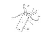
図1は、本実施形態のクリップユニット1の外観を示す図である。図2は、クリップユニット1の断面図である。図1に示すように、クリップユニット1は、アーム部10と、アーム部10の一部が収容された押さえ管(保持部材)20と、アーム部10に取り付けられた糸挟持部30とを備えている。The first embodiment of the present invention will be described with reference to FIGS. 1 to 10.
FIG. 1 is a diagram showing the appearance of the
アーム部10は、第一アーム11および第二アーム12の一対のアームを有する。第一アーム11および第二アーム12は、それぞれ先端部に爪11aおよび12aを有する。図2に示すように、アーム部10の基端部10aにおいて、第一アーム部11と第二アーム12とが接続されている。
アーム部10は、合金を含む金属で形成されている。アーム部10の材質としては、ステンレス鋼、コバルトクロム合金、ニッケルチタン合金などを例示できる。
第一アーム11および第二アーム12は、図1に示す初期状態において拡開した状態である。第一アーム11および第二アーム12は、初期状態から互いに接近すると、材料の弾性力により、初期状態に戻ろうとする付勢力が生じる。The
The
The
押さえ管20は、金属や樹脂等で形成された筒状の部材である。アーム部10の基端部は、押さえ管20内に収容されている。アーム部10の先端部は、押さえ管の先端開口20aから突出している。押さえ管20の基端開口20bは、先端開口20aよりも小さい。 The
図3は、押さえ管20の内部を図2と異なる方向から見た図である。図3に示すように、アーム部10の各アームの中間部には、係止部13が設けられており、係止部13において各アーム11、12の幅方向の寸法が大きくなっている(図3には第一アーム11のみ見えている)。各係止部13は、第一アーム11と第二アーム12とが接近することにより、基端開口20bを通過することができ。基端開口20bを通過後に第一アーム11と第二アーム12とが離間すると、係止部13は、基端開口20bを通過できなくなる。
上述したアーム部10および押さえ管20の基本構造は、公知であり、例えば、PCT国際公開2014/181676に開示されている。FIG. 3 is a view of the inside of the
The basic structures of the
糸挟持部30は、第一アーム11に取り付けられた第一部材31と、第二アーム12に取り付けられた第二部材32とを有する。第一部材31および第二部材32をアームに取り付ける方法としては、接着等を例示できる。
第一部材31および第二部材32は、弾性変形する材料で形成されている。すなわち、第一部材31および第二部材32のヤング率は、アーム部10のヤング率よりも小さい。第一部材31および第二部材32の材料としては、ゴム、シリコーン、エラストマー等を例示できる。第一アーム11および第二アーム12が接近・離間する方向(アーム部10の開閉方向)における第一部材31の寸法D1(図1参照)と第二部材32の寸法D2との和は、アーム部10が閉じたときにおける第一アーム11と第二アーム12との間隔以上である。すなわち、アーム部10が閉じた状態において、第一部材31および第二部材32は弾性変形している。
寸法D1寸法D2との和が過度に大きいと、第一部材31および第二部材32の硬さによっては、爪11aおよび12aで組織を挟む妨げになったり、組織を挟む力を過度に減少させたりする。この観点からは、寸法D1寸法D2との和は、アーム部10が閉じたときにおける第一アーム11と第二アーム12との間隔よりわずかに(例えば、挟持される糸の直径以下の値)小さい値から、わずかに大きい値までの範囲としてもよい。
第一部材31および第二部材32は、第一アーム11および第二アーム12よりも柔らかい。すなわち、第一部材31および第二部材32の表面のビッカース硬度は、第一アーム11および第二アーム12の表面のビッカース硬度よりも低い。The
The
Dimension D1 If the sum with the dimension D2 is excessively large, depending on the hardness of the
The
上述した構成を備えるクリップユニット1の使用時の動作を説明する。クリップユニット1は、ESD等の手技中に粘膜を拳上する際に好適に使用できるため、以下では、クリップユニット1を使った粘膜挙上方法の流れについて説明する。 The operation when the
まず、術者または補助者は、内視鏡を消化管内に挿入し、内視鏡の先端を処置対象の病変付近まで進める。術者は内視鏡で病変を観察して病変周囲のマージンの大きさを検討し、切除する領域の位置及び大きさを決定する。続いて、内視鏡100のチャンネルに高周波ナイフ等の切開具110(図9参照)を挿入して先端開口から切開具110を突出させる。内視鏡100で粘膜及び病変を観察しながら、切開具110を使って切除領域周囲の粘膜にマーキングをした後、粘膜を切開する(ステップA)。 First, the surgeon or assistant inserts the endoscope into the gastrointestinal tract and advances the tip of the endoscope to the vicinity of the lesion to be treated. The surgeon observes the lesion with an endoscope, examines the size of the margin around the lesion, and determines the position and size of the area to be excised. Subsequently, an incision tool 110 (see FIG. 9) such as a high-frequency knife is inserted into the channel of the
続いて術者は、切除領域内の粘膜に糸を固定する。術者は、糸挟持部を備えない一般的なクリップユニット120に糸121の第一端部を結び付ける。次に、切開具110をクリップユニット120が装着されたアプリケータ130と交換し、アプリケータ130を内視鏡100の先端から突出させる。アプリケータ130を操作してクリップユニット120で病変Lの周囲の粘膜Mcを挟むと、図4に示すように、糸121の第一端部が粘膜Mcに固定される(ステップB)。 The surgeon then fixes the thread to the mucosa within the excision area. The operator ties the first end of the
術者は、アプリケータ120を内視鏡100から抜去し、クリップユニット1が装着された第二アプリケータ150をチャンネルに挿入する。術者は、内視鏡100を操作してクリップユニット1を糸に121に接近させ、図5に示すように、第一部材31と第二部材32との間に糸121の中間部を通す(ステップC)。
ステップCを実現するには、クリップユニット1の初期状態における第一部材31と第二部材32との間隔よりも、糸121の直径が小さいことが必要である。The operator removes the
In order to realize step C, it is necessary that the diameter of the
次に術者は、図6に示すように、粘膜Mcと対向する消化管の管壁Wに向かって内視鏡100の先端を移動させる。内視鏡100先端部の移動により、クリップユニット1および糸121が管壁Wに接近する。 Next, as shown in FIG. 6, the operator moves the tip of the
続いて術者は、クリップユニット1を粘膜Mcと対向する管壁Wに固定する。術者は、内視鏡100を前進させて、クリップユニット1の爪11aおよび12aを管壁Wに接触させる。 Subsequently, the operator fixes the
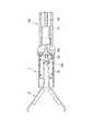
第二アプリケータ150に装着されたクリップユニット1の断面図を図7に示す。第二アプリケータ150は、シース151と、シース151に通された操作ワイヤ152とを備える。操作ワイヤ152は、シース151内で自身の長手軸に沿って移動自在である。操作ワイヤ152の先端には、フック(連結部)153が取り付けられている。押さえ管20は、シース151の先端に配置されている。フック153は、押さえ管20の基端開口20bから押さえ管20内に進入している。フック153がアーム部10の基端部10aに係止されることにより、アプリケータ150にクリップユニット1が装着されている。 A cross-sectional view of the
術者が操作ワイヤ152を引くと、操作ワイヤ152およびフック153が後退する。その結果、アーム部10が押さえ管20に対して後退し、第一アーム11と第二アーム12とが、管壁Wの組織を挟んだまま徐々に接近して閉じていく。
術者がさらに操作ワイヤ152を引くと、操作ワイヤ152およびフック153が押さえ管20の外に移動し、係止部13が基端開口20bを通過する。この状態で術者がフック153とアーム部13との連結を解除すると、図8に示すように、基端開口20bを通過できなくなった係止部13によりアーム部10が閉じた状態(閉状態)が維持され、クリップユニット1が管壁Wに係止される(ステップD)。
ステップDにおいては、第一アーム11と第二アーム12とが閉じることにより、糸挟持部30の第一部材31と第二部材32との間隔は糸121の直径未満であるため、第一部材31と第二部材32とが糸121を挟んで密着する。第一部材31および第二部材32は、少なくとも糸121と接触した部位において、弾性変形し、糸121との間に摩擦力を生じさせる。When the operator pulls the
When the operator further pulls the
In step D, since the
術者は、第二アプリケータ151を内視鏡100のチャンネルから抜去し、チャンネルに切開具110を挿入する。術者は、図9に示すように、切開した部分から切開具110を使って順次粘膜Mc下の粘膜下層を剥離する。必要に応じて、生理食塩液等を用いた切除対象部位の膨隆も行う。粘膜の切開及び粘膜下層の剥離は、ESD等における手技と同様に行うことができる。 The operator removes the
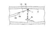
粘膜下層の剥離が進むと、既に剥離が終わった部分の粘膜が手技の妨げになるため、粘膜Mcをさらに拳上する。術者は、切開具110をチャンネルから抜去して把持鉗子160をチャンネルに挿入する。術者は、図10に示すように、内視鏡100から突出した把持鉗子160で糸挟持部30の間を延びた糸121の第二端部を把持して、クリップユニット1から離間する方向に牽引する。糸121は、糸挟持部30で発生した摩擦力により支持されているが、完全に固定されてはいないため、摩擦力を上回る力で牽引されると、クリップユニット1に対して移動する。糸121が移動すると、糸121と接続されたクリップユニット120が、粘膜Mcに固定されたまま管壁Wに接近する。その結果、図10に示すように、粘膜Mcが拳上される(ステップE)。糸121には、粘膜Mcの重さに伴う重力が作用するが、糸挟持部30は、発生した摩擦力により糸121が下方に移動することを防止し、粘膜Mcの挙上状態を維持する。
ステップEにおける糸121の牽引量は、剥離量、切除される粘膜Mcの寸法、拳上される粘膜Mcにかけたいトラクションの大きさ等を考慮して、術者が適宜決定することができる。牽引しすぎた場合は、クリップユニット120とクリップユニット1との間に位置する糸121をクリップユニット1から離間する方向、すなわち、上述した牽引と逆の方向に糸121を牽引すればよい。As the exfoliation of the submucosal layer progresses, the mucosa in the portion where the exfoliation has already been completed interferes with the procedure, so that the mucosal Mc is further raised. The surgeon removes the
The amount of traction of the
術者は、糸121を適宜操作して、粘膜の拳上状態やトラクションの大きさを変更しながら、粘膜Mc下の粘膜下層をさらに剥離する。病変Lを含む所定範囲の粘膜Mcを剥離し終えたら、術者は、クリップユニット120とクリップユニット1との間に位置する糸121を引いてクリップユニット1から引き抜く。 The operator further peels off the submucosal layer under the mucosal Mc while appropriately manipulating the
その後、剥離切除した病変Lおよび粘膜Mcを、クリップユニット120および糸121とともに体外に回収すると、一連の手技が完了する。管壁Wに係止されたクリップユニット1は、一定時間が経過すると、管壁から自然に脱落し、消化管を通って体外に排出される。 Then, the exfoliated and resected lesion L and the mucosal Mc are collected outside the body together with the
本実施形態のクリップユニット1によれば、第一アーム11と第二アーム12との間に配置された糸挟持部30を備えるため、第一アーム11と第二アーム12とで管壁Wに係止しつつ、粘膜Mcに係止された糸を摩擦力により支持することができる。したがって、クリップユニット1を配置する位置に応じて粘膜が牽引される方向を自由に設定できるとともに、粘膜が牽引される方向と関係なく、糸121をクリップユニット1から離間する方向に牽引するだけで粘膜を拳上することができ、操作性が良い。 According to the
また、クリップユニット1を使った粘膜挙上方法においては、管壁Wに取り付けられたクリップユニット1と粘膜に取り付けられたクリップユニット120との間に位置する糸121の長さを自由に変化させることができる。したがって、特許文献1に記載された粘膜牽引具と異なり、粘膜にかかるトラクションの大きさが糸121の物性の影響を受けにくい。その結果、トラクションの大きさを簡便かつ自在に調節することができる。 Further, in the method of raising the mucous membrane using the
本発明の第二実施形態について、図11から図14を参照して説明する。以降の説明において、すでに説明したものと共通する構成については、同一の符号を付して重複する説明を省略する。 A second embodiment of the present invention will be described with reference to FIGS. 11 to 14. In the following description, the same reference numerals will be given to the configurations common to those already described, and duplicate description will be omitted.
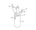
図11は、本実施形態のクリップユニット51の外観図である。図12は、アーム部10の閉状態におけるクリップユニット51の断面図である。クリップユニット51は、糸挟持部30に代えて、第一部材61と第二部材62とを含む糸挟持部60を備えている。さらに、第一アーム11および第二アーム12に代えて、第一アーム65および第二アーム66を備えている。 FIG. 11 is an external view of the
第一部材61および第二部材62は、第一実施形態の糸挟持部30と同様の材料で形成されている。図11に示すように、第一部材61および第二部材62は、第一アーム65および第二アーム66の周囲を覆うように取り付けられている。
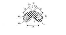
図12は、アーム部10の閉状態における第一アーム65および第二アーム66の一断面を示している。第一アーム65および第二アーム66において、第一部材61および第二部材62が取り付けられた部位の横断面は円形となっている。したがって、第一部材61および第二部材62は、それぞれ第一アーム65および第二アーム66に対して回転できる。The
FIG. 12 shows a cross section of the
第一部材61および第二部材62は、それぞれ凸(convex)となる形状を有し、第一部材61と第二部材62との間に糸121を挟むことができる。
図12に示す断面において、第一部材61および第二部材62の凸形状は、第一アーム65と第二アーム66とを結び、開閉方向と一致する線A(第一線)と、線Aと直交する線B(第二線)との両方に対して傾斜する方向に延びている。第一部材61の凸形状の頂点61aから第一アーム65までの長さL1と、第二部材62の凸形状の頂点62aから第二アーム66までの長さL2との和は、第一アーム65および第二アーム66が閉じた状態における第一アーム65と第二アーム66との距離L3よりも長い。
第一部材61と第一アーム65、および第二部材62と第二アーム66とは、それぞれ両者の間に生じる摩擦力によって、図12に示すように頂点61aと頂点62aとが接近した状態に位置決めされている。
押さえ管20には、マーカー52が設けられている。マーカー52は、上述の線Bが延びる方向において、頂点61aおよび頂点62aが位置する側と反対側の外周面に形成されているが、この態様には限られない。マーカー52は、立体形状であってもよいし、部分的な塗装であってもよい。The
In the cross section shown in FIG. 12, the convex shape of the
The
The holding
本実施形態のクリップユニット51の使用時の動作について説明する。術者は、ステップCにおいて、マーカー52が設けられた側から糸121を糸挟持部60に、すなわち、線Aから頂点61a、62aに向かう方向に通す。ステップDにおいて、糸121は、図13に示すように、第一アーム65および第二アーム66に対して、線Aから離間した位置で第一部材61および第二部材62の頂点61a、62a間に挟まれる。 The operation when the
第一部材61と第二部材62との間に挟まれた糸121が、第二端部側を引っ張ることにより、線Aから頂点61a、62aに向かう方向、すなわちマーカー52から頂点61a、62aに向かう方向に移動する場合、第一部材61と第二部材62は、それぞれ第一アーム65および第二アーム66に対して回転する。その結果、糸121は容易に移動する。
一方、糸121が、第一端部側を引っ張ることにより、頂点61a、62aから線Aに向かう方向、すなわち頂点61a、62aからマーカー52に向かう方向に移動しようとするときも、第一部材61と第二部材62は、第一アーム65および第二アーム66に対して回転しようとする。このとき、長さL1とL2の和がL3より長いため、第一部材61および第二部材62は、その材質等によって、回転できないか、または圧縮変形されつつ回転する。いずれの場合も、糸121は、第一部材61と第二部材62にさらに強く押圧されたり、第一部材61および第二部材62との間に生じる摩擦力が大きくなったりすることにより、大きい抵抗を受ける。その結果、糸121は、線Aから頂点61a、62aに向かう方向に移動する場合よりも移動しにくい。
以上により、糸挟持部60に挟まれた糸121は、挙上する粘膜Mc側に移動しにくく、挙上状態を良好に維持する。さらに、ステップEにおいて糸121を牽引する際の抵抗は小さく、ステップEを簡便に行うことができる。The
On the other hand, when the
As described above, the
本実施形態のクリップユニット51においても、第一実施形態と同様に、トラ簡便に粘膜を挙上でき、かつトラクションの大きさを簡便かつ自在に調節することができる。 In the
さらに、糸挟持部60が、挟まれた糸121が移動する方向の一方においてより大きい抵抗を受けるように構成されているため、糸121を所定の向きで糸挟持部60に通した状態でクリップユニット51を管壁Wに係止することによって、粘膜Mcの重さに好適に耐えつつ、挙上状態の調節を容易に行える。 Further, since the
上述した構成において、第一部材および第二部材の一方のみがアームに対して回転可能に取り付けられ、他方は回転しないように取り付けられてもよい。このような構造でも、概ね同様の効果を奏する。
また、第一部材61および第二部材62の横断面形状は、上述した方向に延びる凸形状を有していれば、上述した形状と異なってもよい。例えば、頂点と反対側が平坦な略D字状であってもよい。In the above configuration, only one of the first member and the second member may be rotatably attached to the arm and the other so as not to rotate. Even with such a structure, almost the same effect can be obtained.
Further, the cross-sectional shapes of the
挟まれた糸121が移動する方向により受ける抵抗が異なる糸挟持部の構造は、上述の構成に限られない。図14に示す変形例の糸挟持部30Aは、第一実施形態と同様の態様で第一アーム11および第二アーム12取り付けられた第一部材31Aおよび32Aを備える。第一部材31Aおよび32Aは、それぞれ対向するアームに向かって突出する複数の凸部35および36を有する。凸部35は、マーカー52から離間する方向に傾く斜面35aを有する。凸部36は、マーカー52から離間する方向に傾く斜面36aを有する。糸挟持部30Aにおいては、第一アーム11と第二アーム12とが閉じた状態において、凸部35と凸部36とが密着するため、糸挟持部30Aに挟まれた糸は、凸部35と凸部36との間で生じる摩擦力で支持される。 The structure of the thread holding portion, which receives different resistance depending on the direction in which the sandwiched
糸挟持部30Aに挟まれた糸は、線Bが延びる方向においてアーム部の範囲内で支持されるが、挟まれた糸が移動する方向に応じて生じる摩擦力が変化し、その結果、糸が受ける抵抗も移動する方向に応じて変化する。したがって、本実施形態の糸挟持部において、線Bが延びる方向において糸を挟む位置がアーム部とずれていることは必須ではない。
この変形例では、ステップCにおいて、凸部35および36の斜面35a、36aが各凸部の頂点に向かって延びる方向に前記糸を通すと、粘膜の挙上状態を良好に維持できる。The thread sandwiched between the thread holding portions 30A is supported within the range of the arm portion in the direction in which the line B extends, but the frictional force generated changes depending on the direction in which the sandwiched thread moves, and as a result, the thread The resistance received by the thread also changes according to the direction of movement. Therefore, in the thread holding portion of the present embodiment, it is not essential that the position where the thread is sandwiched is deviated from the arm portion in the direction in which the line B extends.
In this modification, in step C, when the thread is passed in the direction in which the
本実施形態においてマーカー52は必須ではなく、省略されてもよい。
さらに、凸形状や凸部は、第一部材および第二部材の一部の横断面においてのみ設けられてもよい。In this embodiment, the
Further, the convex shape and the convex portion may be provided only in a partial cross section of the first member and the second member.
以上、本発明の各実施形態について説明したが、本発明の技術範囲は上記実施形態に限定されるものではなく、本発明の趣旨を逸脱しない範囲において各構成要素に種々の変更を加えたり、削除したりすることが可能である。
以下にいくつか変更を例示するが、これらはすべてではなく、それ以外の変更も可能である。これらの変更が2以上適宜組み合わされてもよい。Although each embodiment of the present invention has been described above, the technical scope of the present invention is not limited to the above-described embodiment, and various changes may be made to each component within a range that does not deviate from the gist of the present invention. It can be deleted.
Some changes are illustrated below, but not all, but other changes are possible. Two or more of these changes may be combined as appropriate.
・本発明の糸挟持部において、第一部材および第二部材の一方が実質的に弾性変形しない材料で形成されてもよい。このような構成でも、もう一方が弾性変形することにより、糸との間に摩擦力を生じさせることができる。-In the thread holding portion of the present invention, one of the first member and the second member may be formed of a material that does not substantially elastically deform. Even in such a configuration, a frictional force can be generated between the thread and the thread by elastically deforming the other.
・図15に示す変形例のように、第一部材71と第二部材72とが、押さえ管20に近い側の基端部で接続されてもよい。
・第一部材81と第二部材82とが、アーム部10の閉状態において押さえ管20外に位置してもよい。この場合、図16に示す変形例のように、第一部材81と第二部材82と押さえ管20との間に、リング83を配置すると、第一部材81と第二部材82との間に挟まれた糸が脱落することを防止できる。
図15および図16に示す変形例は、いずれも糸挟持部から糸が外れて糸挟持部と押さえ管との間等に移動することにより摩擦力が生じなくなることを防止できる。-As in the modified example shown in FIG. 15, the
The
In each of the modified examples shown in FIGS. 15 and 16, it is possible to prevent the thread from coming off from the thread holding portion and moving between the thread holding portion and the holding pipe, so that the frictional force is not generated.
・粘膜Mcに係止されるクリップユニット120と、管壁Wに係止される本発明のクリップユニットとは、同様の構造であっても、異なる構造であってもいずれでもよい。同一構造である場合は、クリップユニット120の係止後のアプリケータに本発明のクリップユニットを装着し、アプリケータを共用してもよい。
・クリップユニットを使わずに糸121が粘膜Mcに係止されてもよい。例えば、糸121の接続された曲針を使って粘膜Mcに糸を掛けることにより、糸121を粘膜Mcに係止してもよい。-The
-The
・内視鏡が複数のチャンネルを有する場合、切開具が通るチャンネルと異なるチャンネルに把持鉗子を通してもよい。この場合、ステップEにおいて切開具と把持鉗子との交換作業が不要になり、所要時間を短縮して簡便に粘膜を拳上することができる。-If the endoscope has multiple channels, the grasping forceps may be passed through a channel different from the channel through which the incision tool passes. In this case, it is not necessary to replace the incision tool and the gripping forceps in step E, the required time can be shortened, and the mucous membrane can be easily lifted.
・糸121の端部に、輪やノット等を設けて、把持鉗子でつかみやすくしてもよい。
・ステップDにおいて、糸121の操作は、把持鉗子以外の器具で行われてもよい。例えば、切開具の先端がフック状である場合、上述したように線状部材に輪やノット等を設け、フックを輪やノット等に掛けて線状部材を牽引してもよい。線状部材に、吸引により内視鏡先端部に吸着可能な部材を取り付ける等により、吸引で線状部材を牽引してもよい。これらの場合も、切開具と把持鉗子との交換作業が不要になる。
・糸121の端部が患者の体外まで引き出されてもよい。この場合、ステップDにおいて、術者または補助者が糸121を直接つかんで引くことで粘膜を拳上することができるため、把持鉗子を使わずに粘膜を拳上でき、操作も簡便である。-A ring, a knot, or the like may be provided at the end of the
-In step D, the operation of the
The end of the
本発明は、クリップユニットおよび粘膜挙上システムに適用することができる。The present invention can be applied toclip units and mucosal lifting systems.
1、51 クリップユニット
10 アーム部
10a 基端部
11 第一アーム
12 第二アーム
20 押さえ管
30、60 糸挟持部
31、61、71、81 第一部材
32、62、72、82 第二部材
121 糸
L 病変
Mc 粘膜
W 管壁1,51
Claims (7)
Translated fromJapanese前記アーム部の基端部を収容することにより前記第一アームおよび前記第二アームを閉状態で保持する保持部材と、
前記第一アームおよび前記第二アームの少なくとも一方において、前記爪よりも基端側に取り付けられた糸挟持部と、
を備え、
前記糸挟持部は、前記第一アームと前記第二アームとの間に位置しており、
前記第一アームおよび前記第二アームが拡開した状態において、前記第一アームおよび前記第二アームの開閉方向における前記糸挟持部の寸法は、前記閉状態における前記第一アームと前記第二アームとの間隔以上であり、
前記糸挟持部は、前記閉状態において弾性変形するように構成されている、
粘膜挙上に使用するクリップユニット。An armportion have a first arm and a second arm diverging extends from the proximal end to the distalend, Ruprovided with a pawl which sandwich the biological tissue to the tip of the first arm and the second arm,
A holding member that holds the first arm and the second arm in a closed state by accommodating the base end portion of the arm portion.
In at least one of the first arm and the second arm, a thread holding portion attached to theproximal end side of the claw, and
With
The thread holding portion is located between the first arm and the second arm.
When the first arm and the second arm are expanded, the dimensions of the thread holding portion in the opening / closing direction of the first arm and the second arm are the dimensions of the first arm and the second arm in the closed state. Is more than the interval with
The thread holding portion is configured to be elastically deformed in the closed state.
Clip unitused for raising mucous membranes.
前記糸挟持部は、前記第一アームに取り付けられた第一部材と、前記第二アームに取り付けられた第二部材とを有し、
前記糸の直径は、前記第一アームおよび前記第二アームが拡開した状態における前記第一部材と前記第二部材との間隔より小さく、前記閉状態における前記第一部材と前記第二部材との間隔よりも大きい、
請求項1に記載のクリップユニット。Further provided with a thread sandwiched between the thread sandwiching portions, the thread is further provided.
The thread holding portion has a first member attached to the first arm and a second member attached to the second arm.
The diameter of the thread is smaller than the distance between the first member and the second member when the first arm and the second arm are expanded, and the first member and the second member in the closed state Greater than the interval of
The clip unit according to claim 1.
前記第一部材は、前記第一アームに対して回転可能に取り付けられ、
前記第一部材および前記第二部材の少なくとも一部の横断面は凸形状を有し、
前記凸形状は、前記横断面において、前記第一アームと前記第二アームとを結ぶ第一線および前記第一線に直交する第二線に対して傾斜する方向に延びており、
前記第一アームと前記第一部材とは、前記第一アームと前記第一部材との間に生じる摩擦力により、前記第一部材の凸形状の頂点と前記第二部材の凸形状の頂点とが接近した状態で位置決めされており、
前記横断面における前記第一アームと前記第一部材の凸形状の頂点との距離と、前記横断面における前記第二アームと前記第二部材の凸形状の頂点との距離との和は、前記閉状態における前記第一アームと前記第二アームとの距離よりも長い、
請求項1に記載のクリップユニット。The thread holding portion has a first member attached to the first arm and a second member attached to the second arm.
The first member is rotatably attached to the first arm and
The first member and at least a part of the cross section of the second member have a convex shape.
In the cross section, the convex shape extends in a direction inclined with respect to a first line connecting the first arm and the second arm and a second line orthogonal to the first line.
The first arm and the first member are formed between the convex apex of the first member and the convex apex of the second member due to the frictional force generated between the first arm and the first member. Are positioned in close proximity to each other
The sum of the distance between the first arm and the convex apex of the first member in the cross section and the distance between the second arm and the convex apex of the second member in the cross section is the above. Longer than the distance between the first arm and the second arm in the closed state,
The clip unit according to claim 1.
前記第一部材および前記第二部材の少なくとも一部の横断面は、互いに接近する方向に延びる複数の凸部を有し、
前記複数の凸部の各々は、前記横断面において、前記第一アームと前記第二アームとを結ぶ第一線および前記第一線に直交する第二線に対して傾斜する斜面を有する、
請求項1に記載のクリップユニット。The thread holding portion has a first member attached to the first arm and a second member attached to the second arm.
The first member and at least a part of the cross section of the second member have a plurality of protrusions extending in a direction approaching each other.
Each of the plurality of convex portions has a slope in the cross section that is inclined with respect to a first line connecting the first arm and the second arm and a second line orthogonal to the first line.
The clip unit according to claim 1.
前記アーム部の基端部と前記操作ワイヤとの間に位置し、前記基端部と前記操作ワイヤとを連結する連結部と、
前記操作ワイヤの基端に接続され、前記基端部と前記操作ワイヤとの連結が解除可能となるまで前記操作ワイヤを牽引可能に構成された操作部と、
をさらに備える、
請求項1に記載のクリップユニット。An operation wire that has a tip and a base and is provided so as to be movable along the longitudinal axis.
A connecting portion located between the base end portion of the arm portion and the operation wire and connecting the base end portion and the operation wire, and a connecting portion.
An operation unit that is connected to the base end of the operation wire and is configured to be able to pull the operation wire until the connection between the base end portion and the operation wire can be released.
Further prepare,
The clip unit according to claim 1.
粘膜に固定される第一端部と、前記第一端部とは異なる第二端部と、前記第一端部と前記第二端部との間に設けられ前記クリップユニットの前記糸挟持部に挟まれる中間部とを有する糸と、 The thread holding portion of the clip unit provided between the first end portion fixed to the mucous membrane, the second end portion different from the first end portion, and the first end portion and the second end portion. A thread having an intermediate portion sandwiched between
前記糸の前記第二端部を把持して、前記糸を牽引する把持鉗子と、 A gripping forceps that grips the second end of the thread and pulls the thread,
を備える粘膜挙上システム。 Mucosal elevation system with.
Applications Claiming Priority (1)
| Application Number | Priority Date | Filing Date | Title |
|---|---|---|---|
| PCT/JP2018/030945WO2020039514A1 (en) | 2018-08-22 | 2018-08-22 | Clip unit and mucous membrane elevation method |
Publications (2)
| Publication Number | Publication Date |
|---|---|
| JPWO2020039514A1 JPWO2020039514A1 (en) | 2021-02-15 |
| JP6908791B2true JP6908791B2 (en) | 2021-07-28 |
Family
ID=69591929
Family Applications (1)
| Application Number | Title | Priority Date | Filing Date |
|---|---|---|---|
| JP2020537932AActiveJP6908791B2 (en) | 2018-08-22 | 2018-08-22 | Clip unit and mucosal lifting system |
Country Status (4)
| Country | Link |
|---|---|
| US (1) | US11540839B2 (en) |
| JP (1) | JP6908791B2 (en) |
| CN (2) | CN117159055A (en) |
| WO (1) | WO2020039514A1 (en) |
Families Citing this family (3)
| Publication number | Priority date | Publication date | Assignee | Title |
|---|---|---|---|---|
| CN113303861B (en)* | 2021-05-28 | 2022-04-26 | 中国计量大学 | Vascular ligation device |
| CN113303856B (en)* | 2021-05-28 | 2022-03-29 | 中国计量大学 | Ligature rope mounting plate device |
| CN114043430A (en)* | 2021-12-03 | 2022-02-15 | 中国原子能科学研究院 | Device for operating the hold down assembly |
Family Cites Families (9)
| Publication number | Priority date | Publication date | Assignee | Title |
|---|---|---|---|---|
| WO1994015535A1 (en)* | 1993-01-07 | 1994-07-21 | Hayhurst, John, O. | Clip for suture |
| US5569274A (en)* | 1993-02-22 | 1996-10-29 | Heartport, Inc. | Endoscopic vascular clamping system and method |
| US5634932A (en)* | 1995-10-10 | 1997-06-03 | Industrial & Scientific Designs, Ltd. | Cantilever aneurysm clip system |
| US6921361B2 (en)* | 2000-07-24 | 2005-07-26 | Olympus Corporation | Endoscopic instrument for forming an artificial valve |
| JP2004016662A (en)* | 2002-06-19 | 2004-01-22 | Olympus Corp | Surgery tool |
| JP2005103107A (en)* | 2003-09-30 | 2005-04-21 | Shinshu Tlo:Kk | Medical gripping tool and mounting method for mounting the medical gripping tool in the body |
| EP3061413B1 (en)* | 2008-06-19 | 2022-01-19 | Boston Scientific Scimed, Inc. | Tissue clipping apparatus |
| WO2012092078A1 (en)* | 2010-12-28 | 2012-07-05 | Castle Surgical, Inc. | Sliding overhead clip and associated methods |
| WO2016006407A1 (en)* | 2014-07-10 | 2016-01-14 | オリンパス株式会社 | Endoscopic submucosal dissection device and endoscope system |
- 2018
- 2018-08-22WOPCT/JP2018/030945patent/WO2020039514A1/ennot_activeCeased
- 2018-08-22JPJP2020537932Apatent/JP6908791B2/enactiveActive
- 2018-08-22CNCN202311193932.8Apatent/CN117159055A/enactivePending
- 2018-08-22CNCN201880091376.4Apatent/CN111867492B/enactiveActive
- 2020
- 2020-09-16USUS17/022,168patent/US11540839B2/enactiveActive
Also Published As
| Publication number | Publication date |
|---|---|
| JPWO2020039514A1 (en) | 2021-02-15 |
| US11540839B2 (en) | 2023-01-03 |
| US20210000475A1 (en) | 2021-01-07 |
| CN117159055A (en) | 2023-12-05 |
| CN111867492B (en) | 2023-09-12 |
| WO2020039514A1 (en) | 2020-02-27 |
| CN111867492A (en) | 2020-10-30 |
Similar Documents
| Publication | Publication Date | Title |
|---|---|---|
| US6569085B2 (en) | Methods and apparatus for delivering a medical instrument over an endoscope while the endoscope is in a body lumen | |
| US12096924B2 (en) | Devices and methods for tissue retraction | |
| JP5340722B2 (en) | Endoscopic treatment tool | |
| US6015415A (en) | Polypectomy snare instrument | |
| US10653436B2 (en) | Medical device for cutting | |
| US9592066B2 (en) | Selectively bendable remote gripping tool | |
| JP6273298B2 (en) | Operable medical device | |
| US20130211415A1 (en) | Steerable tissue manipulation medical devices and related methods of use | |
| US20160038133A1 (en) | Medical devices and related methods of use | |
| JP6908791B2 (en) | Clip unit and mucosal lifting system | |
| JP7542161B2 (en) | ENDOSCOPIC CLIP HAVING POSITIVE LOCK - Patent application | |
| CN118660672A (en) | Tissue traction device and its delivery system | |
| CN118678922A (en) | Devices, systems, and methods for tissue distraction | |
| JP7546851B2 (en) | Suction head for vacuum-operated surgical graspers | |
| JP6923755B2 (en) | Mucosal fist device | |
| JP2022062923A (en) | Manufacturing method of endoscope traction clip, endoscope treatment tool and endoscope traction clip |
Legal Events
| Date | Code | Title | Description |
|---|---|---|---|
| A521 | Request for written amendment filed | Free format text:JAPANESE INTERMEDIATE CODE: A523 Effective date:20200805 | |
| A621 | Written request for application examination | Free format text:JAPANESE INTERMEDIATE CODE: A621 Effective date:20200805 | |
| TRDD | Decision of grant or rejection written | ||
| A01 | Written decision to grant a patent or to grant a registration (utility model) | Free format text:JAPANESE INTERMEDIATE CODE: A01 Effective date:20210601 | |
| A61 | First payment of annual fees (during grant procedure) | Free format text:JAPANESE INTERMEDIATE CODE: A61 Effective date:20210701 | |
| R151 | Written notification of patent or utility model registration | Ref document number:6908791 Country of ref document:JP Free format text:JAPANESE INTERMEDIATE CODE: R151 | |
| R250 | Receipt of annual fees | Free format text:JAPANESE INTERMEDIATE CODE: R250 | |
| R250 | Receipt of annual fees | Free format text:JAPANESE INTERMEDIATE CODE: R250 |