JP6908217B2 - Charging support device and charging support method - Google Patents
Charging support device and charging support methodDownload PDFInfo
- Publication number
- JP6908217B2 JP6908217B2JP2018029808AJP2018029808AJP6908217B2JP 6908217 B2JP6908217 B2JP 6908217B2JP 2018029808 AJP2018029808 AJP 2018029808AJP 2018029808 AJP2018029808 AJP 2018029808AJP 6908217 B2JP6908217 B2JP 6908217B2
- Authority
- JP
- Japan
- Prior art keywords
- vehicle
- power transmission
- transmission device
- image
- bird
- Prior art date
- Legal status (The legal status is an assumption and is not a legal conclusion. Google has not performed a legal analysis and makes no representation as to the accuracy of the status listed.)
- Active
Links
Images


Classifications
- H—ELECTRICITY
- H02—GENERATION; CONVERSION OR DISTRIBUTION OF ELECTRIC POWER
- H02J—CIRCUIT ARRANGEMENTS OR SYSTEMS FOR SUPPLYING OR DISTRIBUTING ELECTRIC POWER; SYSTEMS FOR STORING ELECTRIC ENERGY
- H02J7/00—Circuit arrangements for charging or depolarising batteries or for supplying loads from batteries
- H02J7/0047—Circuit arrangements for charging or depolarising batteries or for supplying loads from batteries with monitoring or indicating devices or circuits
- B—PERFORMING OPERATIONS; TRANSPORTING
- B60—VEHICLES IN GENERAL
- B60L—PROPULSION OF ELECTRICALLY-PROPELLED VEHICLES; SUPPLYING ELECTRIC POWER FOR AUXILIARY EQUIPMENT OF ELECTRICALLY-PROPELLED VEHICLES; ELECTRODYNAMIC BRAKE SYSTEMS FOR VEHICLES IN GENERAL; MAGNETIC SUSPENSION OR LEVITATION FOR VEHICLES; MONITORING OPERATING VARIABLES OF ELECTRICALLY-PROPELLED VEHICLES; ELECTRIC SAFETY DEVICES FOR ELECTRICALLY-PROPELLED VEHICLES
- B60L53/00—Methods of charging batteries, specially adapted for electric vehicles; Charging stations or on-board charging equipment therefor; Exchange of energy storage elements in electric vehicles
- B60L53/10—Methods of charging batteries, specially adapted for electric vehicles; Charging stations or on-board charging equipment therefor; Exchange of energy storage elements in electric vehicles characterised by the energy transfer between the charging station and the vehicle
- B60L53/12—Inductive energy transfer
- B60L53/124—Detection or removal of foreign bodies
- B—PERFORMING OPERATIONS; TRANSPORTING
- B60—VEHICLES IN GENERAL
- B60L—PROPULSION OF ELECTRICALLY-PROPELLED VEHICLES; SUPPLYING ELECTRIC POWER FOR AUXILIARY EQUIPMENT OF ELECTRICALLY-PROPELLED VEHICLES; ELECTRODYNAMIC BRAKE SYSTEMS FOR VEHICLES IN GENERAL; MAGNETIC SUSPENSION OR LEVITATION FOR VEHICLES; MONITORING OPERATING VARIABLES OF ELECTRICALLY-PROPELLED VEHICLES; ELECTRIC SAFETY DEVICES FOR ELECTRICALLY-PROPELLED VEHICLES
- B60L53/00—Methods of charging batteries, specially adapted for electric vehicles; Charging stations or on-board charging equipment therefor; Exchange of energy storage elements in electric vehicles
- B60L53/10—Methods of charging batteries, specially adapted for electric vehicles; Charging stations or on-board charging equipment therefor; Exchange of energy storage elements in electric vehicles characterised by the energy transfer between the charging station and the vehicle
- B60L53/12—Inductive energy transfer
- B60L53/126—Methods for pairing a vehicle and a charging station, e.g. establishing a one-to-one relation between a wireless power transmitter and a wireless power receiver
- B—PERFORMING OPERATIONS; TRANSPORTING
- B60—VEHICLES IN GENERAL
- B60L—PROPULSION OF ELECTRICALLY-PROPELLED VEHICLES; SUPPLYING ELECTRIC POWER FOR AUXILIARY EQUIPMENT OF ELECTRICALLY-PROPELLED VEHICLES; ELECTRODYNAMIC BRAKE SYSTEMS FOR VEHICLES IN GENERAL; MAGNETIC SUSPENSION OR LEVITATION FOR VEHICLES; MONITORING OPERATING VARIABLES OF ELECTRICALLY-PROPELLED VEHICLES; ELECTRIC SAFETY DEVICES FOR ELECTRICALLY-PROPELLED VEHICLES
- B60L53/00—Methods of charging batteries, specially adapted for electric vehicles; Charging stations or on-board charging equipment therefor; Exchange of energy storage elements in electric vehicles
- B60L53/30—Constructional details of charging stations
- B60L53/35—Means for automatic or assisted adjustment of the relative position of charging devices and vehicles
- B60L53/37—Means for automatic or assisted adjustment of the relative position of charging devices and vehicles using optical position determination, e.g. using cameras
- G—PHYSICS
- G06—COMPUTING OR CALCULATING; COUNTING
- G06T—IMAGE DATA PROCESSING OR GENERATION, IN GENERAL
- G06T11/00—2D [Two Dimensional] image generation
- G06T11/001—Texturing; Colouring; Generation of texture or colour
- G—PHYSICS
- G06—COMPUTING OR CALCULATING; COUNTING
- G06T—IMAGE DATA PROCESSING OR GENERATION, IN GENERAL
- G06T11/00—2D [Two Dimensional] image generation
- G06T11/60—Editing figures and text; Combining figures or text
- G—PHYSICS
- G06—COMPUTING OR CALCULATING; COUNTING
- G06T—IMAGE DATA PROCESSING OR GENERATION, IN GENERAL
- G06T7/00—Image analysis
- G06T7/70—Determining position or orientation of objects or cameras
- G—PHYSICS
- G06—COMPUTING OR CALCULATING; COUNTING
- G06V—IMAGE OR VIDEO RECOGNITION OR UNDERSTANDING
- G06V20/00—Scenes; Scene-specific elements
- G06V20/20—Scenes; Scene-specific elements in augmented reality scenes
- G—PHYSICS
- G06—COMPUTING OR CALCULATING; COUNTING
- G06V—IMAGE OR VIDEO RECOGNITION OR UNDERSTANDING
- G06V20/00—Scenes; Scene-specific elements
- G06V20/50—Context or environment of the image
- G06V20/56—Context or environment of the image exterior to a vehicle by using sensors mounted on the vehicle
- G06V20/58—Recognition of moving objects or obstacles, e.g. vehicles or pedestrians; Recognition of traffic objects, e.g. traffic signs, traffic lights or roads
- G—PHYSICS
- G06—COMPUTING OR CALCULATING; COUNTING
- G06V—IMAGE OR VIDEO RECOGNITION OR UNDERSTANDING
- G06V30/00—Character recognition; Recognising digital ink; Document-oriented image-based pattern recognition
- G06V30/10—Character recognition
- G06V30/22—Character recognition characterised by the type of writing
- G06V30/224—Character recognition characterised by the type of writing of printed characters having additional code marks or containing code marks
- H—ELECTRICITY
- H02—GENERATION; CONVERSION OR DISTRIBUTION OF ELECTRIC POWER
- H02J—CIRCUIT ARRANGEMENTS OR SYSTEMS FOR SUPPLYING OR DISTRIBUTING ELECTRIC POWER; SYSTEMS FOR STORING ELECTRIC ENERGY
- H02J50/00—Circuit arrangements or systems for wireless supply or distribution of electric power
- H02J50/90—Circuit arrangements or systems for wireless supply or distribution of electric power involving detection or optimisation of position, e.g. alignment
- B—PERFORMING OPERATIONS; TRANSPORTING
- B60—VEHICLES IN GENERAL
- B60L—PROPULSION OF ELECTRICALLY-PROPELLED VEHICLES; SUPPLYING ELECTRIC POWER FOR AUXILIARY EQUIPMENT OF ELECTRICALLY-PROPELLED VEHICLES; ELECTRODYNAMIC BRAKE SYSTEMS FOR VEHICLES IN GENERAL; MAGNETIC SUSPENSION OR LEVITATION FOR VEHICLES; MONITORING OPERATING VARIABLES OF ELECTRICALLY-PROPELLED VEHICLES; ELECTRIC SAFETY DEVICES FOR ELECTRICALLY-PROPELLED VEHICLES
- B60L2250/00—Driver interactions
- B60L2250/16—Driver interactions by display
- G—PHYSICS
- G06—COMPUTING OR CALCULATING; COUNTING
- G06T—IMAGE DATA PROCESSING OR GENERATION, IN GENERAL
- G06T2207/00—Indexing scheme for image analysis or image enhancement
- G06T2207/30—Subject of image; Context of image processing
- G06T2207/30248—Vehicle exterior or interior
- G06T2207/30252—Vehicle exterior; Vicinity of vehicle
- G06T2207/30261—Obstacle
- G—PHYSICS
- G06—COMPUTING OR CALCULATING; COUNTING
- G06T—IMAGE DATA PROCESSING OR GENERATION, IN GENERAL
- G06T2207/00—Indexing scheme for image analysis or image enhancement
- G06T2207/30—Subject of image; Context of image processing
- G06T2207/30248—Vehicle exterior or interior
- G06T2207/30252—Vehicle exterior; Vicinity of vehicle
- G06T2207/30264—Parking
- H—ELECTRICITY
- H02—GENERATION; CONVERSION OR DISTRIBUTION OF ELECTRIC POWER
- H02J—CIRCUIT ARRANGEMENTS OR SYSTEMS FOR SUPPLYING OR DISTRIBUTING ELECTRIC POWER; SYSTEMS FOR STORING ELECTRIC ENERGY
- H02J2310/00—The network for supplying or distributing electric power characterised by its spatial reach or by the load
- H02J2310/40—The network being an on-board power network, i.e. within a vehicle
- H02J2310/48—The network being an on-board power network, i.e. within a vehicle for electric vehicles [EV] or hybrid vehicles [HEV]
- H—ELECTRICITY
- H02—GENERATION; CONVERSION OR DISTRIBUTION OF ELECTRIC POWER
- H02J—CIRCUIT ARRANGEMENTS OR SYSTEMS FOR SUPPLYING OR DISTRIBUTING ELECTRIC POWER; SYSTEMS FOR STORING ELECTRIC ENERGY
- H02J50/00—Circuit arrangements or systems for wireless supply or distribution of electric power
- H02J50/10—Circuit arrangements or systems for wireless supply or distribution of electric power using inductive coupling
- H02J50/12—Circuit arrangements or systems for wireless supply or distribution of electric power using inductive coupling of the resonant type
- H—ELECTRICITY
- H04—ELECTRIC COMMUNICATION TECHNIQUE
- H04N—PICTORIAL COMMUNICATION, e.g. TELEVISION
- H04N23/00—Cameras or camera modules comprising electronic image sensors; Control thereof
- H04N23/60—Control of cameras or camera modules
- H04N23/63—Control of cameras or camera modules by using electronic viewfinders
- Y—GENERAL TAGGING OF NEW TECHNOLOGICAL DEVELOPMENTS; GENERAL TAGGING OF CROSS-SECTIONAL TECHNOLOGIES SPANNING OVER SEVERAL SECTIONS OF THE IPC; TECHNICAL SUBJECTS COVERED BY FORMER USPC CROSS-REFERENCE ART COLLECTIONS [XRACs] AND DIGESTS
- Y02—TECHNOLOGIES OR APPLICATIONS FOR MITIGATION OR ADAPTATION AGAINST CLIMATE CHANGE
- Y02T—CLIMATE CHANGE MITIGATION TECHNOLOGIES RELATED TO TRANSPORTATION
- Y02T10/00—Road transport of goods or passengers
- Y02T10/60—Other road transportation technologies with climate change mitigation effect
- Y02T10/70—Energy storage systems for electromobility, e.g. batteries
- Y—GENERAL TAGGING OF NEW TECHNOLOGICAL DEVELOPMENTS; GENERAL TAGGING OF CROSS-SECTIONAL TECHNOLOGIES SPANNING OVER SEVERAL SECTIONS OF THE IPC; TECHNICAL SUBJECTS COVERED BY FORMER USPC CROSS-REFERENCE ART COLLECTIONS [XRACs] AND DIGESTS
- Y02—TECHNOLOGIES OR APPLICATIONS FOR MITIGATION OR ADAPTATION AGAINST CLIMATE CHANGE
- Y02T—CLIMATE CHANGE MITIGATION TECHNOLOGIES RELATED TO TRANSPORTATION
- Y02T10/00—Road transport of goods or passengers
- Y02T10/60—Other road transportation technologies with climate change mitigation effect
- Y02T10/7072—Electromobility specific charging systems or methods for batteries, ultracapacitors, supercapacitors or double-layer capacitors
- Y—GENERAL TAGGING OF NEW TECHNOLOGICAL DEVELOPMENTS; GENERAL TAGGING OF CROSS-SECTIONAL TECHNOLOGIES SPANNING OVER SEVERAL SECTIONS OF THE IPC; TECHNICAL SUBJECTS COVERED BY FORMER USPC CROSS-REFERENCE ART COLLECTIONS [XRACs] AND DIGESTS
- Y02—TECHNOLOGIES OR APPLICATIONS FOR MITIGATION OR ADAPTATION AGAINST CLIMATE CHANGE
- Y02T—CLIMATE CHANGE MITIGATION TECHNOLOGIES RELATED TO TRANSPORTATION
- Y02T90/00—Enabling technologies or technologies with a potential or indirect contribution to GHG emissions mitigation
- Y02T90/10—Technologies relating to charging of electric vehicles
- Y02T90/12—Electric charging stations
- Y—GENERAL TAGGING OF NEW TECHNOLOGICAL DEVELOPMENTS; GENERAL TAGGING OF CROSS-SECTIONAL TECHNOLOGIES SPANNING OVER SEVERAL SECTIONS OF THE IPC; TECHNICAL SUBJECTS COVERED BY FORMER USPC CROSS-REFERENCE ART COLLECTIONS [XRACs] AND DIGESTS
- Y02—TECHNOLOGIES OR APPLICATIONS FOR MITIGATION OR ADAPTATION AGAINST CLIMATE CHANGE
- Y02T—CLIMATE CHANGE MITIGATION TECHNOLOGIES RELATED TO TRANSPORTATION
- Y02T90/00—Enabling technologies or technologies with a potential or indirect contribution to GHG emissions mitigation
- Y02T90/10—Technologies relating to charging of electric vehicles
- Y02T90/14—Plug-in electric vehicles
Landscapes
- Engineering & Computer Science (AREA)
- Power Engineering (AREA)
- Theoretical Computer Science (AREA)
- Physics & Mathematics (AREA)
- General Physics & Mathematics (AREA)
- Transportation (AREA)
- Mechanical Engineering (AREA)
- Multimedia (AREA)
- Computer Networks & Wireless Communication (AREA)
- Computer Vision & Pattern Recognition (AREA)
- Electric Propulsion And Braking For Vehicles (AREA)
- Current-Collector Devices For Electrically Propelled Vehicles (AREA)
- Charge And Discharge Circuits For Batteries Or The Like (AREA)
- Arrangement Or Mounting Of Propulsion Units For Vehicles (AREA)
- Closed-Circuit Television Systems (AREA)
Description
Translated fromJapanese本発明は、充電支援装置、及び、充電支援方法に関する。 The present invention relates to a charging support device and a charging support method.
電気モータによって走行する電気自動車(EV)や電気モータとガソリンエンジンとの併用によって走行するプラグインハイブリッド自動車(PHV)の普及に伴い、これら車両の動作のための電力を蓄えるバッテリに対して、非接触で電力を供給する技術がある。非接触で電力を供給する方法として、送電ユニットの送電コイルと車両の受電コイルとを非接触の状態で対向配置させ、電磁誘導または磁気共鳴の原理を利用して電力供給を行う方法がある。 With the widespread use of electric vehicles (EVs) that run on electric motors and plug-in hybrid vehicles (PHVs) that run on the combined use of electric motors and gasoline engines, the batteries that store power for the operation of these vehicles are not. There is a technology to supply power by contact. As a method of supplying electric power in a non-contact manner, there is a method in which a power transmission coil of a power transmission unit and a power receiving coil of a vehicle are arranged to face each other in a non-contact state, and power is supplied by using the principle of electromagnetic induction or magnetic resonance.
車両を充電する非接触充電システムとしては、駐車場内の各駐車スペースにそれぞれ送電ユニット(充電パッド)を設置し、駐車スペースに駐車している車両に対して送電を行うことによって非接触充電を実行する方式が一般的である。このような非接触充電システムにおいて、車両を駐車スペースに駐車する際に、車両に設置されるカメラによる画像から生成される俯瞰画像を車両内のディスプレイに表示し、送電ユニットの位置と車両の位置とを確認することができる技術がある。 As a non-contact charging system for charging vehicles, a power transmission unit (charging pad) is installed in each parking space in the parking lot, and non-contact charging is performed by transmitting power to the vehicle parked in the parking space. The method of doing is common. In such a non-contact charging system, when the vehicle is parked in the parking space, a bird's-eye view image generated from the image taken by the camera installed in the vehicle is displayed on the display inside the vehicle, and the position of the power transmission unit and the position of the vehicle are displayed. There is a technology that can confirm that.
しかし、このような非接触充電システムにおいて、車両に対する送電ユニットの位置が充電するための適切な位置であるか否かを判断することは難しかった。 However, in such a non-contact charging system, it has been difficult to determine whether the position of the power transmission unit with respect to the vehicle is an appropriate position for charging.
本発明は、非接触充電システムによる車両の充電において、車両に対する送電装置の位置が適切であるか否かを容易に判断することができる技術を提供することを目的とする。 An object of the present invention is to provide a technique capable of easily determining whether or not the position of a power transmission device with respect to a vehicle is appropriate in charging a vehicle by a non-contact charging system.
上記課題を解決するため、本発明は、以下の手段を採用する。
即ち、第1の態様は、
車両底面の受電部に対して前記車両外部の送電装置から充電を行う際の充電支援装置であって、
車両画像とカメラで撮影された車両周辺とを俯瞰画像で表示する制御部を有し、
前記制御部は、前記受電部を示す表示と前記送電装置を示す表示を行い、所定の充電効率が得られる位置に前記受電部が位置したとき、送電装置を示す表示の色または大きさを変えて表示する、充電支援装置とする。In order to solve the above problems, the present invention employs the following means.
That is, the first aspect is
It is a charging support device for charging the power receiving unit on the bottom of the vehicle from the power transmission device outside the vehicle.
It has a control unit that displays a bird's-eye view image of the vehicle image and the surroundings of the vehicle taken by the camera.
The control unit displays a display indicating the power receiving unit and a display indicating the power transmission device, and when the power receiving unit is located at a position where a predetermined charging efficiency can be obtained, the color or size of the display indicating the power transmission device is changed. It is a charging support device that displays.
開示の態様は、プログラムが情報処理装置によって実行されることによって実現されてもよい。即ち、開示の構成は、上記した態様における各手段が実行する処理を、情報処理装置に対して実行させるためのプログラム、或いは当該プログラムを記録したコンピュータ読み取り可能な記録媒体として特定することができる。また、開示の構成は、上記した各手段が実行する処理を情報処理装置が実行する方法をもって特定されてもよい。開示の構成は、上記した各手段が実行する処理を行う情報処理装置を含むシステムとして特定さ
れてもよい。The aspect of disclosure may be realized by executing the program by an information processing device. That is, the structure of the disclosure can be specified as a program for causing the information processing apparatus to execute the process executed by each means in the above-described embodiment, or as a computer-readable recording medium on which the program is recorded. Further, the structure of the disclosure may be specified by a method in which the information processing apparatus executes the processing executed by each of the above-mentioned means. The configuration of the disclosure may be specified as a system including an information processing device that performs processing executed by each of the above means.
本発明によれば、非接触充電システムによる車両の充電において、車両に対する送電装置の位置が適切であるか否かを容易に判断することができる。 According to the present invention, it is possible to easily determine whether or not the position of the power transmission device with respect to the vehicle is appropriate in charging the vehicle by the non-contact charging system.
以下、図面を参照して実施形態について説明する。実施形態の構成は例示であり、発明の構成は、開示の実施形態の具体的構成に限定されない。発明の実施にあたって、実施形態に応じた具体的構成が適宜採用されてもよい。 Hereinafter, embodiments will be described with reference to the drawings. The configuration of the embodiment is an example, and the configuration of the invention is not limited to the specific configuration of the disclosed embodiment. In carrying out the invention, a specific configuration according to the embodiment may be appropriately adopted.
〈実施形態〉
(構成例)
図1は、本実施形態の充電支援装置を含む非接触充電システムの構成例を示す図である。図1に示す非接触充電システム1は、電気モータによって駆動する車両100、送電装置200を含む。車両100は、例えば、電気自動車やハイブリット自動車である。車両100は、充電支援装置10、受電部20、出力部30、撮像部40、車両部50を含む
。充電支援装置10は、車両100の運転者に、送電装置200で車両100を充電するに際して、車両100の位置が適切であるか否かを出力する。充電支援装置10は、制御部11、情報取得部12、画像認識部13を含む。車両100は、車両100の受電部20が送電装置200に近接させたとき、車両100のバッテリを充電することができる。送電装置200は、例えば、駐車スペースの路面に設置される。送電装置200は、駐車スペースの路面に埋め込まれて設置されてもよい。<Embodiment>
(Configuration example)
FIG. 1 is a diagram showing a configuration example of a non-contact charging system including the charging support device of the present embodiment. The
制御部11は、送電装置200による充電の支援を行うための演算処理を行う制御手段である。制御部11は、情報取得部12により充電支援装置10が搭載される車両100に関する情報等を取得する。制御部11は、画像認識部13により車両100の外側に向けて設置される撮像部40が撮影した画像を取得する。制御部11は、出力部30を介して、車両100の充電を支援する情報を出力する。制御部11、情報取得部12、画像認識部13は、一体化して、1つの制御部として動作してもよい。 The
情報取得部12は、充電支援装置10が搭載される車両の状態等の情報を、車両部50から取得する。情報取得部12は、例えば、シフトレバーからシフトレバーポジション、車速センサから車両の速度、加速度センサから車両の加速度、ブレーキからブレーキ圧、サイドブレーキからサイドブレーキの状態、レーダECUから物標等の検出状況、ハンドルから操舵角等を取得する。情報取得部12が取得する情報は、これらに限定されるものではない。情報取得部12は、車両100の制御部に接続されてこれらの情報を取得してもよい。情報取得部12は、取得した情報を記憶手段に格納する。 The
画像認識部13は、車両100の外側に向けて設置される撮像部40が撮影した画像を取得する。画像認識部13には、複数の撮像部40が接続されてもよい。画像認識部13は、撮像部40が撮影した画像から、車両100の上方を視点として車両100の方向を俯瞰した車両100の周囲を含む画像を生成しうる。画像認識部13は、歪み補正、トリミング、コントラストの変更など、所定の画像処理を撮影画像に行って画像を生成してもよい。 The
受電部20は、受電コイル、バッテリを含み、送電装置200から供給される電力をコイルで受け、バッテリに充電する。バッテリは、車両100の電気モータを駆動するエネルギー等の供給源として使用される。受電部20は、送電装置200との間で通信するための通信手段を含み得る。受電コイルの巻軸に直交する面は、例えば、地面に平行である。車両100における受電部20の位置は、あらかじめ、記憶手段に格納されている。 The
出力部30は、撮像部40で撮影された画像、制御部11で生成された画像等を出力する。出力部30は、ディスプレイ、スピーカ等である。車両100に搭載されるカーナビゲーションシステムのディスプレイ等が、出力部30として使用されてもよい。ディスプレイは、車両100の運転席から視認できる位置に設置される。 The
撮像部40は、例えば、魚眼レンズや広角レンズを有するカメラである。撮像部40は、車両100の外側に向けて設置される。撮像部40は、複数のカメラを含み得る。本実施形態では、車両100の前後左右に1つずつ、計4台のカメラが車両100に設置されている。 The
車両部50は、車両100の各構成部を含む。車両部50は、例えば、シフトレバー、車速センサ、加速度センサ、ハンドル、ブレーキ、サイドブレーキ、レーダECU、温度センサ、マイク、カメラ等を含む。シフトレバーは、車両のギア等を変更するレバーである。シフトレバー110のポジションが、例えば、「R(リバース)」である場合、車両は後退する。レーダECUは、車両の周囲の物標を検出し、車両の周囲の物標と車両との
距離等の演算等を行う電子制御ユニット(Electric Control Unit)である。レーダEC
Uは、マイクロ波や撮像部40等が撮影した画像等を使用して、物標との距離等の演算を行う。車速センサは、車両の走行速度を検出するセンサである。車速センサは、例えば、タイヤの回転角、タイヤの半径等により、車速を検出し、出力する。加速度センサは、車両の加速度を検出し、出力するセンサである。The
U calculates the distance to the target and the like using microwaves, images taken by the
送電装置200は、送電コイル、アンプ、通信手段、制御手段等を含む。送電装置200は、送電コイルを介して、受電部20を有する車両100に電力を供給する。送電コイルの巻軸に直交する面は、地面に平行である。送電装置200の送電コイルの位置と、車両100の受電部20の受電コイルの位置とが適切でないと、充電効率が下がる。効率のよい充電のためには、送電装置200の送電コイルの位置と、車両100の受電部20の受電コイルの位置とを適切にすることが求められる。例えば、送電装置200の送電コイルの中心及び車両100の受電部20の受電コイルの中心が、車両100の情報から俯瞰したときに、一致すると充電効率が最も高くなる。また、送電コイルの中心位置と受電コイルの中心位置とが離れるほど、受電効率が低くなる。 The
図2は、情報処理装置のハードウェア構成例を示す図である。図2に示す情報処理装置90は、一般的なコンピュータの構成を有している。充電支援装置10は、図2に示すような情報処理装置90を用いることによって、実現される。図2の情報処理装置90は、プロセッサ91、メモリ92、記憶部93、入力部94、出力部95、通信制御部96を有する。これらは、互いにバスによって接続される。メモリ92及び記憶部93は、コンピュータ読み取り可能な記録媒体である。情報処理装置のハードウェア構成は、図2に示される例に限らず、適宜構成要素の省略、置換、追加が行われてもよい。 FIG. 2 is a diagram showing a hardware configuration example of the information processing device. The
情報処理装置90は、プロセッサ91が記録媒体に記憶されたプログラムをメモリ92の作業領域にロードして実行し、プログラムの実行を通じて各構成部等が制御されることによって、所定の目的に合致した機能を実現することができる。 The
プロセッサ91は、例えば、CPU(Central Processing Unit)やDSP(Digital Signal Processor)である。 The
メモリ92は、例えば、RAM(Random Access Memory)やROM(Read Only Memory)を含む。メモリ92は、主記憶装置とも呼ばれる。 The
記憶部93は、例えば、EPROM(Erasable Programmable ROM)、ハードディスク
ドライブ(HDD、Hard Disk Drive)である。また、記憶部93は、リムーバブルメデ
ィア、即ち可搬記録媒体を含むことができる。リムーバブルメディアは、例えば、USB(Universal Serial Bus)メモリ、あるいは、CD(Compact Disc)やDVD(Digital Versatile Disc)のようなディスク記録媒体である。記憶部93は、二次記憶装置とも呼ばれる。The
記憶部93は、情報処理装置90で使用される、各種のプログラム、各種のデータ及び各種のテーブルを読み書き自在に記録媒体に格納する。記憶部93には、オペレーティングシステム(Operating System :OS)、各種プログラム、各種テーブル等が格納される。記憶部93に格納される情報は、メモリ92に格納されてもよい。また、メモリ92に格納される情報は、記憶部93に格納されてもよい。 The
オペレーティングシステムは、ソフトウェアとハードウェアとの仲介、メモリ空間の管理、ファイル管理、プロセスやタスクの管理等を行うソフトウェアである。オペレーティングシステムは、通信インタフェースを含む。通信インタフェースは、通信制御部96を
介して接続される他の外部装置等とデータのやり取りを行うプログラムである。外部装置等には、例えば、他の情報処理装置、外部記憶装置等が含まれる。The operating system is software that mediates between software and hardware, manages memory space, manages files, manages processes and tasks, and so on. The operating system includes a communication interface. The communication interface is a program that exchanges data with other external devices and the like connected via the
入力部94は、キーボード、ポインティングデバイス、ワイヤレスリモコン、タッチパネル等を含む。また、入力部94は、カメラのような映像や画像の入力装置や、マイクロフォンのような音声の入力装置を含むことができる。 The input unit 94 includes a keyboard, a pointing device, a wireless remote controller, a touch panel, and the like. Further, the input unit 94 can include a video or image input device such as a camera or an audio input device such as a microphone.
出力部95は、LCD(Liquid Crystal Display)、EL(Electroluminescence)パ
ネル、CRT(Cathode Ray Tube)ディスプレイ、PDP(Plasma Display Panel)等の表示装置、プリンタ等の出力装置を含む。また、出力部95は、スピーカのような音声の出力装置を含むことができる。The output unit 95 includes a display device such as an LCD (Liquid Crystal Display), an EL (Electroluminescence) panel, a CRT (Cathode Ray Tube) display, a PDP (Plasma Display Panel), and an output device such as a printer. Further, the output unit 95 can include an audio output device such as a speaker.
通信制御部96は、他の装置と接続し、情報処理装置90と他の装置との間の通信を制御する。通信制御部96は、例えば、LAN(Local Area Network)インタフェースボード、無線通信のための無線通信回路、有線通信のための通信回路である。LANインタフェースボードや無線通信回路は、インターネット等のネットワークに接続される。 The
(動作例)
図3及び図4は、充電支援装置による充電支援の動作フローの例を示す図である。図3の「A」、「B」、「C」は、それぞれ、図4の「A」、「B」、「C」に接続する。図3及び図4の動作フローは、充電支援装置10を搭載する車両100から充電支援装置10に電力が供給された場合に実行される動作フローである。車両100の駆動源が作動状態、例えば、システム電源がオンになった場合、図3及び図4の動作フローが開始される。(Operation example)
3 and 4 are diagrams showing an example of an operation flow of charging support by the charging support device. "A", "B", and "C" in FIG. 3 are connected to "A", "B", and "C" in FIG. 4, respectively. The operation flow of FIGS. 3 and 4 is an operation flow executed when electric power is supplied to the
S101では、充電支援装置10の情報取得部12は、車両部50の車速センサより、車両100の車速を取得する。制御部11は、情報取得部12が取得した車両100の車速が所定速度以下であるか否かを判定する。ここで、所定速度未満の速度は、車両100が駐車スペースに駐車しようとしていると考えられる速度である。所定速度は、例えば、11km/hである。車両100の車速が所定速度未満である場合(S101;YES)、処理がS102に進む。車両100の車速が所定速度以上である場合(S101;NO)、処理がS110に進む。 In S101, the
S102では、充電支援装置10の画像認識部13は、撮像部40で撮影された画像を取得する。撮像部40は、車両100の外側に向けて設置されるため、撮像部40は、車両100の周辺画像を撮影する。画像認識部13は、撮像部40で撮影された車両100の周辺画像に基づいて、俯瞰画像を生成する。俯瞰画像は、車両100の上方を視点として、車両100の方向を見た画像である。俯瞰画像における車両100の画像として、例えば、あらかじめ車両100の記憶手段に格納されている車両100を上方から撮影した画像が使用される。制御部11は、画像認識部13が生成した俯瞰画像を、出力部30のディスプレイに表示させる。出力部30のディスプレイは、画像認識部13が生成した俯瞰画像を表示する。車両100の利用者(運転者)は、ディスプレイに表示される俯瞰画像を見ることで、車両100の周辺の状況を認識することができる。俯瞰画像は、車両100の前方及び後方に取り付けられた撮像部40によって撮影された画像を使用すればよい。車両100は、前方または後方に進行するものの、横方向には進行しないため、横方向に送電装置200が存在しても、車両100がその上方に移動できないためである。 In S102, the
S103では、制御部11は、撮像部40が撮影した車両100の周辺画像において、障害物を検出する。障害物は、例えば、車両100のタイヤの4つの底面によって形成される平面(路面、地面)に存在する車両100以外の物体である。障害物には、送電装置
200も含まれ得る。制御部11は、複数のカメラ画像、パターンマッチング等により、車両100の周辺における障害物を検出する。制御部11は、車両100が有するセンサ等を用いて、車両100の周辺に存在する障害物を検出してもよい。In S103, the
S104では、制御部11は、S103で障害物を検出したか否かを判定する。障害物を検出しなかった場合(S104;NO)、処理がS110に進む。このとき、送電装置200も検出されていないことを意味する。障害物を検出した場合(S104;YES)、処理がS105に進む。このとき、送電装置200を検出した可能性があることを意味する。 In S104, the
S105では、制御部11は、S103で検出した各障害物の位置を検出する。制御部11は、画像における各障害物の座標等から、各障害物の位置を検出する。制御部11は、障害物の位置を、例えば、車両100を基準とした相対的な3次元位置として検出する。制御部11は、位置とともに、障害物(送電装置を示すマークであってもよい)の形状を検出し、記憶手段に、障害物の位置、形状を記憶してもよい。 In S105, the
S106では、制御部11は、俯瞰画像において、障害物の少なくとも一部が車両100の下に隠れたか否かを判定する。制御部11は、今回生成された俯瞰画像における各障害物と、前回生成された俯瞰画像における各障害物とを比較して、前回の俯瞰画像において、全体が見えていたある障害物の少なくとも一部が、今回の俯瞰画像において車両100の下に隠れたか否かを判定する。この障害物の少なくとも一部が車両100の下に隠れたかの判定は、予め用意された車両の大きさ情報に基づいて判定しても良いし、画像生成時の車両周囲の撮影死角領域を含んで判定しても良い。制御部11は、障害物の位置や形状、情報取得部12が取得する車両100の速度や操舵角、前回の俯瞰画像と今回の俯瞰画像との撮影時刻の時間差に基づいて、障害物の少なくとも一部が車両100の下に隠れたか否かを判定する。障害物の少なくとも一部が車両100の下に隠れた場合(S106;YES)、処理がS107に進む。障害物が車両100の下に隠れていない場合(S106;NO)、処理がS110に進む。 In S106, the
S107では、制御部11は、少なくとも一部が車両100の下に隠れた障害物が送電装置200であるか否かを判定する。制御部11は、俯瞰画像における障害物の色、形状当に基づいて、周知のパターンマッチング等により、少なくとも一部が車両の下に隠れた障害物が、送電装置200(充電パッド)であるか否かを判定する。送電装置200の画像は、例えば、記憶手段に格納されている。少なくとも一部が車両100の下に隠れた障害物が送電装置200である場合(S107;YES)、処理がS108に進む。少なくとも一部が車両100の下に隠れた障害物が送電装置200でない場合(S107;NO)、処理がS110に進む。 In S107, the
S108では、制御部11は、少なくとも一部が車両100の下に隠れた障害物(送電装置200)の画像を、俯瞰画像において、車両100の画像に重畳して出力部30に表示する。送電装置200の画像は、あらかじめ用意された送電装置の画像、車両100の下に隠れる前に撮影された画像などが使用され得る。ここで、制御部11は、情報取得部12から車両100の移動方向、移動距離を随時取得する。これにより、制御部11は、送電装置200が俯瞰画像から見えなくなっても、送電装置200の位置を算出することができる。情報取得部12は、車両部50の速度センサやハンドル等から車両の速度や操舵角等を取得することで、車両100の移動方向、移動距離を算出することができる。移動方向、移動距離の算出は、制御部11で行われてもよい。 In S108, the
また、制御部11は、出力部30に表示される俯瞰画像の元の画像が撮影された時刻から合成画像の表示時刻(現時刻)までの処理遅れの時間に車両100が進んだ方向、距離
(移動方向、移動距離)を予測し、当該予測に基づいて、送電装置200の表示位置を修正してもよい。車両100の進んだ方向、距離は、車両100の車速、操舵角等から容易に求められる。これにより、画像の処理遅れ時間により画面上での送電装置200の位置と、実際の送電装置200の位置とがずれることを抑制することができる。Further, the
S109では、制御部11は、現在の送電装置200の位置における充電効率に基づいた通知を、車両100の運転者(ユーザ)に対して、行う。ここでは、制御部11は、俯瞰画像に表示される送電装置200の位置(送電コイルの中心位置)と、車両100の受電部20の位置(受電コイルの中心位置)との距離を求める。充電効率は、当該距離の関数である。当該距離が長くなるほど、充電効率が下がる。充電効率は、例えば、当該距離に反比例する。よって、制御部11は、当該距離から充電効率を求めることができる。また、制御部11は、受電部20に送電装置200との通信を行わせ、受電部20と送電装置200との充電効率を測定してもよい。制御部11は、俯瞰画像における送電装置200の色を、充電効率に基づいて、変更する。制御部11は、充電効率が第1所定値未満である場合、送電装置200の色を赤色とする。また、制御部11は、充電効率が第1所定値以上になり、値が大きくなるにつれて、送電装置200の色を、赤色から徐々に黄色、緑色に変化するようにする。さらに充電効率が大きくなり、制御部11は、充電効率が第2所定値(>第1所定値)以上になると、送電装置200の色を緑色とする。すなわち、車両が最適な充電位置に位置したことを報知する。これにより、車両100の運転者(ユーザ)は、俯瞰画像における送電装置の色が緑色になるように、駐車することで、バッテリの充電効率を向上させることができる。車両100の運転者は、出力部30に表示される送電装置200の表示形態が充電効率に応じて変化することで、現在の送電装置200の位置における充電効率を認識することができる。 In S109, the
S110では、制御部11は、車両100のシステムの電源がOFFにされたか否かを判定する。システムの電源がOFFにされた場合(S110;YES)、図3及び図4の動作フローは、終了する。システムの電源がOFFにされていない場合(S110;NO)、処理がS101に戻る。
尚、S109では充電効率を求め、充電効率に応じた色で送電装置200の色を変更するとしたが、充電効率を求めることと、送電装置200の位置(例えば送電コイルの中心位置)および車両100の受電部20の位置(例えば受電コイルの中心位置)との距離を求めることとは同義である。すなわち、充電効率と、前記距離は1対1で対応するため、当該距離を求め、距離に基づいて送電装置200の色を変更するようにしてもよい。例えば、制御部11は、前記距離が第1所定距離以上である場合、送電装置200の色を赤色とする。また、制御部11は、前記距離が第1所定距離未満になり、距離が小さくなるにつれて、送電装置200の色を、赤色から徐々に黄色、緑色に変化するようにする。さらに前記距離が小さくなり、制御部11は、前記距離が第2所定距離(<第1所定距離)以下になると、送電装置200の色を緑色とする。これにより、車両100の運転者(ユーザ)は、俯瞰画像における送電装置の色が緑色になるように、駐車することで、バッテリの充電効率を向上させることができる。以下の説明においても、同様に充電効率を送電装置200と受電部20との距離に変更することができる。In S110, the
In S109, the charging efficiency was obtained and the color of the
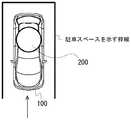
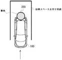
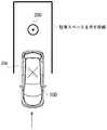
図5、図6、図7は、上記の実施形態における出力部に表示される俯瞰画像の例を示す図である。図5、図6、図7では、駐車スペースを示す枠線、車両100、送電装置200が示されている。車両100は、枠線で示される駐車スペースに駐車しようとしている。当該駐車スペースには、送電装置200が存在する。各図における矢印は、車両100の進行方向を示す。尚、図5〜図7に示す車両100はあらかじめ記憶手段に格納されている画像であり、撮像画像を基に生成された俯瞰画像に車両100の画像が重畳表示される。また、図5における送電装置200は、実際の画像であり、図6、図7における送電装置200は記憶手段に格納されている画像である。図5では、車両100は、後退して
送電装置200に近づいている。図6では、車両100が図5の状態から後退して、送電装置200の一部が車両100下に隠れている。しかし、俯瞰画像において、送電装置200は、車両100の上に重畳して表示されている。また、充電効率が第1所定値以上、あるいは送電装置200と受電部20との距離が第1所定距離以下であるため、送電装置200が黄色で表示されている。図7では、車両100が図6の状態からさらに後退して、送電装置200が完全に車両100下に隠れている。しかし、俯瞰画像において、送電装置200は、車両100の上に重畳して表示されている。また、充電効率が第2所定値以上、あるいは送電装置200と受電部20との距離が第2所定距離以下であるため、送電装置200が緑色で表示されている。車両100の運転者は、ここ(充電するための最適位置)で、車両100を止めることで、高い充電効率で、バッテリを充電することができる。尚、障害物が検出され車両が送電装置に位置するまでの間、車両周辺の俯瞰画像が随時更新され現在の周囲状況がリアルタイムで表示される。これにより使用者は周囲の状況を把握しながら送電装置200の位置に車両を誘導することができる。また送電装置200に対する車両の移動は、運転者の手動運転であっても良いし、車両の自動運転でもよい。自動運転で駐車する際は、駐車エリア内で車両が送電装置200上の最適位置となる位置を駐車の最適位置として車両を停車させるよう制御する。5, FIG. 6 and FIG. 7 are diagrams showing an example of a bird's-eye view image displayed on the output unit in the above embodiment. In FIGS. 5, 6 and 7, a frame line indicating a parking space, a
(変形例1)
上記のS109では、充電効率に応じて、俯瞰画像に表示される送電装置200の色を変化させることで、充電効率を容易に認識できるようにした。ここでは、俯瞰画像に表示される送電装置200の大きさを充電効率に応じて変化させることで、充電効率を容易に認識できるようにする。(Modification example 1)
In S109 described above, the charging efficiency can be easily recognized by changing the color of the
図8、図9、図10は、変形例2における出力部に表示される俯瞰画像の例を示す図である。図8、図9、図10では、駐車スペースを示す枠線、車両100、送電装置200が示されている。車両100は、枠線で示される駐車スペースに駐車しようとしている。当該駐車スペースには、送電装置200が存在する。各図における矢印は、車両100の進行方向を示す。図8では、車両100は、後退して送電装置200に近づいている。図9では、車両100が図8の状態から後退して、送電装置200の一部が車両100下に隠れている。しかし、俯瞰画像において、送電装置200は、車両100の上に重畳して表示されている。また、充電効率が第1所定値以上であるため、送電装置200が図8よりも大きく表示されている。図10では、車両100が図9の状態からさらに後退して、送電装置200が完全に車両100下に隠れている。しかし、俯瞰画像において、送電装置200は、車両100の上に重畳して表示されている。また、充電効率が第2所定値以上であるため、送電装置200がさらに大きく表示されている。車両100の運転者は、ここで、車両100を止めることで、高い充電効率で、バッテリを充電することができる。 8, 9, and 10 are diagrams showing an example of a bird's-eye view image displayed on the output unit in the modified example 2. In FIGS. 8, 9, and 10, a frame line indicating a parking space, a
また、制御部11は、俯瞰画像において、送電装置200の位置(送電コイルの中心位置)及び受電部20の位置(受電コイルの中心位置)が移動しないように、俯瞰画像の表示を拡大縮小してもよい。これにより、車両100に送電装置200が近づくほど、全体の表示が拡大されて表示される。車両100の運転者は、俯瞰画像が拡大された状態で、車両100を止めることで、高い充電効率で、バッテリを充電することができる。 Further, the
(変形例2)
上記のS109では、充電効率に応じて、俯瞰画像に表示される送電装置200の色を変化させることで、充電効率を容易に認識できるようにした。ここでは、俯瞰画像に表示される送電装置200の色及び大きさを充電効率に応じて変化させることで、充電効率を容易に認識できるようにする。(Modification 2)
In S109 described above, the charging efficiency can be easily recognized by changing the color of the
図11、図12、図13は、変形例3における出力部に表示される俯瞰画像の例を示す図である。図11、図12、図13では、駐車スペースを示す枠線、車両100、送電装置200が示されている。車両100は、枠線で示される駐車スペースに駐車しようとしている。当該駐車スペースには、送電装置200が存在する。各図における矢印は、車両100の進行方向を示す。図11では、車両100は、後退して送電装置200に近づいている。図12では、車両100が図11の状態から後退して、送電装置200の一部が車両100下に隠れている。しかし、俯瞰画像において、送電装置200は、車両100の上に重畳して表示されている。また、充電効率が第1所定値以上であるため、送電装置200が図11よりも大きく表示され、さらに、黄色で表示されている。図13では、車両100が図12の状態からさらに後退して、送電装置200が完全に車両100下に隠れている。しかし、俯瞰画像において、送電装置200は、車両100の上に重畳して表示されている。また、充電効率が第2所定値以上であるため、送電装置200がさらに大きく表示され、さらに、緑色で表示されている。車両100の運転者は、より容易に、充電効率の高い位置(充電するための最適位置)を認識することができる。 11, FIG. 12, and FIG. 13 are diagrams showing an example of a bird's-eye view image displayed on the output unit in the modified example 3. In FIGS. 11, 12, and 13, a frame line indicating a parking space, a
(変形例3)
上記のS109では、充電効率に応じて、俯瞰画像に表示される送電装置200の色を変化させることで、充電効率を容易に認識できるようにした。ここでは、制御部11は、出力部30のスピーカから出す音を、充電効率に応じて変化させることで、充電効率を容易に認識できるようにする。これにより、車両100の運転者は、ディスプレイを見なくても、充電効率を容易に認識できるようになる。このとき、制御部11、画像認識部13は、俯瞰画像を表示しなくても、生成しなくてもよい。(Modification example 3)
In S109 described above, the charging efficiency can be easily recognized by changing the color of the
(変形例4)
上記のS109では、充電効率に応じて、俯瞰画像に表示される送電装置200の色を変化させることで、充電効率を容易に認識できるようにした。充電効率は、車両100の受電部20と、送電装置200とが最も近づいたときに最大となる。ここでは、俯瞰画像に表示される送電装置200の位置と、車両100の受電部20の位置とを表示することで、車両100の運転者が車両100の受電部20を送電装置200に近づけることを容易にする。これにより、車両100の運転者は、送電装置200の位置と車両100の受電部20の位置との距離に依存する充電効率を容易に認識できるようになる。(Modification example 4)
In S109 described above, the charging efficiency can be easily recognized by changing the color of the
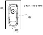
図14、図15、図16は、上記の実施形態における出力部に表示される俯瞰画像の変形例を示す図である。図14、図15、図16では、駐車スペースを示す枠線、車両100、送電装置200が示されている。また、送電装置200の中心には、所定のマーク(黒丸印)が示されている。車両100には、受電部20の位置が所定のマーク20A(X印)で示されている。車両100は、枠線で示される駐車スペースに駐車しようとしている。当該駐車スペースには、送電装置200が存在する。各図における矢印は、車両100の進行方向を示す。図14では、車両100は、後退して送電装置200に近づいている。図15では、車両100が図14の状態から後退して、送電装置200の一部が車両100下に隠れている。しかし、俯瞰画像において、送電装置200は、車両100の上に重畳して表示されている。また、送電装置200の中心には、所定のマーク(黒丸印)が示されている。さらに、車両100の受電部20の位置が所定のマーク20Aで示されている。運転者は、送電装置200の中心が、受電部20の所定のマーク20Aの中心と重なるように、車両100を操作することで、受電効率の高い位置に車両100を駐車することができる。図16では、車両100が図15の状態からさらに後退して、送電装置200が完全に車両100下に隠れている。しかし、俯瞰画像において、送電装置200は、車両100の上に重畳して表示されている。また、俯瞰画像において、車両100の受電部20の位置を示す所定のマーク20Aが、車両100の上に重畳して表示されている。車両100の運転者は、送電装置200の中心と、受電部20の中心と合わせるよう
に(送電装置200の所定のマークと受電部20の所定のマーク20Aとを合わせるように)、車両100を止めることで、高い充電効率で、バッテリを充電することができる。運転者は、出力部30に表示される送電装置200を示す所定のマークと受電部20を示す所定のマーク20Aとを確認して運転することにより、容易に、送電装置200と受電部20との位置合わせをできるようになる。
尚、変形例4では、送電装置200と受電部20の位置を示すマーク20Aを表示するようにしたが、これまでの実施形態と同様、充電効率に応じて、送電装置200の色や大きさ(マークや形状含む)を変化させてもよく、また充電効率に応じて、受電部20の位置を示すマーク20Aの色や大きさ(マークや形状含む)を変化させてもよい。すなわち、充電効率に応じて、送電装置200または受電部20の位置を示すマーク20Aの少なくとも一方の色や大きさ(マークや形状含む)を変化させてもよい。14, 15, and 16 are diagrams showing a modified example of the bird's-eye view image displayed on the output unit in the above embodiment. In FIGS. 14, 15, and 16, a frame line indicating a parking space, a
In the modified example 4, the
(その他)
上記の動作フローでは、送電装置200の一部が俯瞰画像において車両100の下に隠れた後に、充電効率を求めて、充電効率に応じた通知をしている。ここでは、S103において、障害物を検出する際に、障害物が送電装置200であるか否かを判定し、送電装置200が俯瞰画像において車両100の下に隠れていなくても、充電効率を算出し、充電効率の応じた通知を行う。これにより、車両100の運転者は、より早い段階で、充電効率を認識することができる。(others)
In the above operation flow, after a part of the
検出された障害物は、俯瞰画像において、強調表示されてもよい。強調表示は、障害物の輪郭線を太くする、障害物を点滅表示させることなどにより実現できる。障害物が強調表示されることで、車両100の運転者は、障害物を認識しやすくなる。また、送電装置200は、強調表示されなくてもよい。障害物のうち送電装置200だけが、強調表示されてもよい。送電装置200が異なる表示をされることで、送電装置200を認識しやすくなる。 The detected obstacle may be highlighted in the bird's-eye view image. The highlighting can be realized by thickening the outline of the obstacle, blinking the obstacle, and the like. By highlighting the obstacle, the driver of the
送電装置200が地面に埋め込まれている場合、送電装置200は、地面と一体化するため、障害物として認識されない。この場合、制御部11は、地面に記載された送電装置200を示す所定のマークを認識することで、送電装置200を検出する。 When the
(実施形態の作用、効果)
充電支援装置10は、送電装置200の位置に対応する充電効率に応じた通知を行うことで、車両100の運転者に、充電効率を容易に認識させることができる。運転者は、容易に、充電効率の高い位置に車両100を駐車させることができる。(Action and effect of the embodiment)
The charging
以上、本発明の実施形態を説明したが、これらはあくまで例示にすぎず、本発明はこれらに限定されるものではなく、特許請求の範囲の趣旨を逸脱しない限りにおいて、当業者の知識に基づく種々の変更が可能である。また、各構成例等は、可能な限りにおいて、組み合わされて実施され得る。 Although the embodiments of the present invention have been described above, these are merely examples, and the present invention is not limited thereto and is based on the knowledge of those skilled in the art as long as it does not deviate from the scope of claims. Various changes are possible. In addition, each configuration example and the like can be implemented in combination as much as possible.
〈コンピュータ読み取り可能な記録媒体〉
コンピュータその他の機械、装置(以下、コンピュータ等)に上記いずれかの機能を実現させるプログラムをコンピュータ等が読み取り可能な記録媒体に記録することができる。そして、コンピュータ等に、この記録媒体のプログラムを読み込ませて実行させることにより、その機能を提供させることができる。<Computer readable recording medium>
A program that enables a computer or other machine or device (hereinafter, computer or the like) to realize any of the above functions can be recorded on a recording medium that can be read by the computer or the like. Then, the function can be provided by causing a computer or the like to read and execute the program of this recording medium.
ここで、コンピュータ等が読み取り可能な記録媒体とは、データやプログラム等の情報を電気的、磁気的、光学的、機械的、または化学的作用によって蓄積し、コンピュータ等から読み取ることができる記録媒体をいう。このような記録媒体内には、CPU、メモリ
等のコンピュータを構成する要素を設け、そのCPUにプログラムを実行させてもよい。Here, a recording medium that can be read by a computer or the like is a recording medium that can store information such as data and programs by electrical, magnetic, optical, mechanical, or chemical action and can be read from the computer or the like. To say. In such a recording medium, elements constituting a computer such as a CPU and a memory may be provided, and the CPU may execute a program.
また、このような記録媒体のうちコンピュータ等から取り外し可能なものとしては、例えばフレキシブルディスク、光磁気ディスク、CD−ROM、CD−R/W、DVD、DAT、8mmテープ、メモリカード等がある。 Further, among such recording media, those that can be removed from a computer or the like include, for example, a flexible disk, a magneto-optical disk, a CD-ROM, a CD-R / W, a DVD, a DAT, an 8 mm tape, a memory card, and the like.
また、コンピュータ等に固定された記録媒体としてハードディスクやROM等がある。 In addition, there are hard disks, ROMs, and the like as recording media fixed to computers and the like.
1 非接触充電システム
100 車両
10 充電支援装置
11 制御部
12 情報取得部
13 画像認識部
20 受電部
30 出力部
40 撮像部
50 車両部
200 送電装置1
Claims (4)
Translated fromJapaneseあって、
車両画像とカメラで撮影された車両周辺とを俯瞰画像で表示する制御部を有し、
前記制御部は、
前記カメラの撮影画像から前記送電装置の位置を検出し、
前記送電装置が前記車両の下に隠れた後は、前記車両の移動方向および移動距離に基づき前記送電装置の位置を算出すると共に、前記受電部の位置を示す第1の画像と前記送電装置の位置を示す第2の画像を前記俯瞰画像に表示し、
所定の充電効率が得られる位置に前記受電部が位置したとき、少なくとも前記第1の画像または前記第2の画像の一方の色または大きさを変えて表示すると共に、前記送電装置が前記受電部に近づくと拡大された前記俯瞰画像を表示する
ことを特徴とする充電支援装置。It is a charging support device when charging the power receiving unit on the bottom of the vehicle from the power transmission device outside the vehicle.
It has a control unit that displays a bird's-eye view image of the vehicle image and the surroundings of the vehicle taken by the camera.
The control unit
The position of the power transmission device is detected from the image taken by the camera, and the position of the power transmission device is detected.
After the power transmission device is hidden under the vehicle, the position of the power transmission device is calculated based on the movement direction and the movement distance of the vehicle, and the first image showing the position of the power receiving unit and the power transmission device of the power transmission device. A second image showing the position is displayed on the bird's-eye view image,
When the power receiving unit is positioned at a position where a predetermined charging efficiency can be obtained, at least one of the first image and the second image is displayed in a different color or size, and thepower transmission device displays the power receiving unit. A charging support device characterizedin that an enlarged bird's-eye view image is displayed when approaching.
あって、 There,
車両画像とカメラで撮影された車両周辺とを俯瞰画像で表示する制御部を有し、 It has a control unit that displays a bird's-eye view image of the vehicle image and the surroundings of the vehicle taken by the camera.
前記制御部は、 The control unit
前記カメラの撮影画像から前記送電装置の位置を検出し、 The position of the power transmission device is detected from the image taken by the camera, and the position of the power transmission device is detected.
前記送電装置が前記車両の下に隠れた後は、前記車両の移動方向および移動距離に基づき前記送電装置の位置を算出すると共に、前記受電部の位置を示す第1の画像と前記送電装置の位置を示す第2の画像を前記俯瞰画像に表示し、 After the power transmission device is hidden under the vehicle, the position of the power transmission device is calculated based on the movement direction and the movement distance of the vehicle, and the first image showing the position of the power receiving unit and the power transmission device of the power transmission device. A second image showing the position is displayed on the bird's-eye view image,
前記受電部の充電効率に応じて、少なくとも前記第1の画像または前記第2の画像の一方の色および形状を変えて表示する The color and shape of at least one of the first image and the second image are changed and displayed according to the charging efficiency of the power receiving unit.
ことを特徴とする充電支援装置。A charging support device characterized by this.
車両画像とカメラで撮影された車両周辺とを俯瞰画像で表示し、
前記カメラの撮影画像から前記送電装置の位置を検出し、
前記送電装置が前記車両の下に隠れた後は、前記車両の移動方向および移動距離に基づき前記送電装置の位置を算出すると共に、前記受電部の位置を示す第1の画像と前記送電装置の位置を示す第2の画像を前記俯瞰画像に表示し、
所定の充電効率が得られる位置に前記受電部が位置したとき、少なくとも前記第1の画像または前記第2の画像の一方の色または大きさを変えて表示すると共に、前記送電装置が前記受電部に近づくと拡大された前記俯瞰画像を表示する
ことを特徴とする充電支援方法。The charging support device for charging the power receiving unit on the bottom of the vehicle from the power transmission device outside the vehicle
A bird's-eye view image of the vehicle image and the surroundings of the vehicle taken by the camera is displayed.
The position of the power transmission device is detected from the image taken by the camera, and the position of the power transmission device is detected.
After the power transmission device is hidden under the vehicle, the position of the power transmission device is calculated based on the movement direction and the movement distance of the vehicle, and the first image showing the position of the power receiving unit and the power transmission device of the power transmission device. A second image showing the position is displayed on the bird's-eye view image,
When the power receiving unit is positioned at a position where a predetermined charging efficiency can be obtained, at least one of the first image and the second image is displayed in a different color or size, and thepower transmission device displays the power receiving unit. A charging support method characterizedin that an enlarged bird's-eye view image is displayed when approaching.
車両画像とカメラで撮影された車両周辺とを俯瞰画像で表示し、 A bird's-eye view image of the vehicle image and the surroundings of the vehicle taken by the camera is displayed.
前記カメラの撮影画像から前記送電装置の位置を検出し、 The position of the power transmission device is detected from the image taken by the camera, and the position of the power transmission device is detected.
前記送電装置が前記車両の下に隠れた後は、前記車両の移動方向および移動距離に基づき前記送電装置の位置を算出すると共に、前記受電部の位置を示す第1の画像と前記送電装置の位置を示す第2の画像を前記俯瞰画像に表示し、 After the power transmission device is hidden under the vehicle, the position of the power transmission device is calculated based on the movement direction and the movement distance of the vehicle, and the first image showing the position of the power receiving unit and the power transmission device of the power transmission device. A second image showing the position is displayed on the bird's-eye view image,
前記受電部の充電効率に応じて、少なくとも前記第1の画像または前記第2の画像の一方の色および形状を変えて表示する The color and shape of at least one of the first image and the second image are changed and displayed according to the charging efficiency of the power receiving unit.
ことを特徴とする充電支援方法。A charging support method characterized by that.
Applications Claiming Priority (2)
| Application Number | Priority Date | Filing Date | Title |
|---|---|---|---|
| JP2017033796 | 2017-02-24 | ||
| JP2017033796 | 2017-02-24 |
Related Child Applications (1)
| Application Number | Title | Priority Date | Filing Date |
|---|---|---|---|
| JP2020196729ADivisionJP7149318B2 (en) | 2017-02-24 | 2020-11-27 | Charging support device and charging support method |
Publications (3)
| Publication Number | Publication Date |
|---|---|
| JP2018143089A JP2018143089A (en) | 2018-09-13 |
| JP2018143089A5 JP2018143089A5 (en) | 2021-01-14 |
| JP6908217B2true JP6908217B2 (en) | 2021-07-21 |
Family
ID=63112473
Family Applications (2)
| Application Number | Title | Priority Date | Filing Date |
|---|---|---|---|
| JP2018029808AActiveJP6908217B2 (en) | 2017-02-24 | 2018-02-22 | Charging support device and charging support method |
| JP2020196729AActiveJP7149318B2 (en) | 2017-02-24 | 2020-11-27 | Charging support device and charging support method |
Family Applications After (1)
| Application Number | Title | Priority Date | Filing Date |
|---|---|---|---|
| JP2020196729AActiveJP7149318B2 (en) | 2017-02-24 | 2020-11-27 | Charging support device and charging support method |
Country Status (4)
| Country | Link |
|---|---|
| US (2) | US10541547B2 (en) |
| JP (2) | JP6908217B2 (en) |
| CN (2) | CN108501740B (en) |
| DE (1) | DE102017130173A1 (en) |
Families Citing this family (7)
| Publication number | Priority date | Publication date | Assignee | Title |
|---|---|---|---|---|
| JP6513119B2 (en)* | 2017-03-31 | 2019-05-15 | 本田技研工業株式会社 | Contactless power transmission system |
| US11173798B2 (en)* | 2018-02-12 | 2021-11-16 | Ford Global Technologies, Llc | Systems and methods for vehicle wireless charging |
| DE102018210757A1 (en)* | 2018-06-29 | 2020-01-02 | Bayerische Motoren Werke Aktiengesellschaft | Vehicle positioning for conductive energy transfer or for an automatic refueling process |
| DE102018210756A1 (en)* | 2018-06-29 | 2020-01-02 | Bayerische Motoren Werke Aktiengesellschaft | Vehicle positioning for conductive energy transfer or for an automatic refueling process |
| JP2021150997A (en) | 2020-03-16 | 2021-09-27 | 本田技研工業株式会社 | Parking support system |
| JP7044820B2 (en)* | 2020-03-16 | 2022-03-30 | 本田技研工業株式会社 | Parking support system |
| JP7142050B2 (en)* | 2020-03-18 | 2022-09-26 | 本田技研工業株式会社 | PARKING ASSIST SYSTEM, PARKING ASSIST DEVICE, AND VEHICLE |
Family Cites Families (77)
| Publication number | Priority date | Publication date | Assignee | Title |
|---|---|---|---|---|
| EP0788212B1 (en)* | 1996-01-30 | 2002-04-17 | Sumitomo Wiring Systems, Ltd. | Connection system and connection method for an electric automotive vehicle |
| JP2003291688A (en)* | 2002-04-03 | 2003-10-15 | Denso Corp | Display method, driving support device, program |
| JP2004114879A (en) | 2002-09-27 | 2004-04-15 | Clarion Co Ltd | Parking assisting device, and image display device |
| JP3938559B2 (en) | 2003-08-28 | 2007-06-27 | アイシン精機株式会社 | Vehicle reverse support device |
| JP4646538B2 (en) | 2004-03-26 | 2011-03-09 | アルパイン株式会社 | Electronic device having navigation function and night view map display method |
| JP4020128B2 (en)* | 2005-04-22 | 2007-12-12 | トヨタ自動車株式会社 | Target position setting device and parking support device having the same |
| JP4853712B2 (en) | 2006-12-28 | 2012-01-11 | アイシン精機株式会社 | Parking assistance device |
| KR101084025B1 (en)* | 2007-07-31 | 2011-11-16 | 가부시키가이샤 도요다 지도숏키 | Parking Assistance, Vehicle-side Device of Parking Assistance, Parking Assistance Method and Parking Assistance Program |
| US8466654B2 (en)* | 2008-07-08 | 2013-06-18 | Qualcomm Incorporated | Wireless high power transfer under regulatory constraints |
| US20100277121A1 (en) | 2008-09-27 | 2010-11-04 | Hall Katherine L | Wireless energy transfer between a source and a vehicle |
| CN101764435B (en)* | 2008-12-22 | 2014-09-10 | 爱信艾达株式会社 | Power reception guidance device |
| EP2199142B1 (en)* | 2008-12-22 | 2013-04-17 | Aisin Aw Co., Ltd. | Guidance device for charging vehicle battery |
| US20100201309A1 (en)* | 2009-02-10 | 2010-08-12 | Meek Ivan C | Systems and methods for coupling a vehicle to an external grid and/or network |
| US8033349B2 (en)* | 2009-03-12 | 2011-10-11 | Ford Global Technologies, Inc. | Auto-seek electrical connection for a plug-in hybrid electric vehicle |
| US9873347B2 (en) | 2009-03-12 | 2018-01-23 | Wendell Brown | Method and apparatus for automatic charging of an electrically powered vehicle |
| JP4831374B2 (en)* | 2009-03-27 | 2011-12-07 | アイシン・エィ・ダブリュ株式会社 | Driving support device, driving support method, and driving support program |
| JP5177433B2 (en)* | 2009-03-30 | 2013-04-03 | アイシン・エィ・ダブリュ株式会社 | Power reception guidance device, power reception guidance method, and power reception guidance program |
| EP2454119A2 (en)* | 2009-07-15 | 2012-05-23 | Conductix-Wampfler AG | System for inductively charging vehicles, comprising an electronic positioning aid |
| JP5035643B2 (en)* | 2010-03-18 | 2012-09-26 | アイシン精機株式会社 | Image display device |
| US10343535B2 (en)* | 2010-04-08 | 2019-07-09 | Witricity Corporation | Wireless power antenna alignment adjustment system for vehicles |
| WO2011132272A1 (en)* | 2010-04-21 | 2011-10-27 | トヨタ自動車株式会社 | Vehicle parking assistance device and electric vehicle equipped with same |
| KR101760632B1 (en)* | 2010-05-19 | 2017-07-21 | 퀄컴 인코포레이티드 | Adaptive wireless energy transfer system |
| US8513915B2 (en)* | 2010-10-21 | 2013-08-20 | GM Global Technology Operations LLC | Vehicle alignment for inductive charging |
| JP5527431B2 (en)* | 2010-12-27 | 2014-06-18 | 日産自動車株式会社 | Non-contact charger |
| US9184633B2 (en)* | 2011-02-03 | 2015-11-10 | Denso Corporation | Non-contact power supply control device, non-contact power supply system, and non-contact power charge system |
| JP2012209882A (en) | 2011-03-30 | 2012-10-25 | Panasonic Corp | On-vehicle display device |
| US10090885B2 (en)* | 2011-04-13 | 2018-10-02 | Qualcomm Incorporated | Antenna alignment and vehicle guidance for wireless charging of electric vehicles |
| US9180783B1 (en)* | 2011-04-22 | 2015-11-10 | Penilla Angel A | Methods and systems for electric vehicle (EV) charge location color-coded charge state indicators, cloud applications and user notifications |
| US20130037339A1 (en)* | 2011-08-12 | 2013-02-14 | Delphi Technologies, Inc. | Parking assist for a vehicle equipped with for wireless vehicle charging |
| US8816637B2 (en)* | 2011-10-06 | 2014-08-26 | Ford Global Technologies, Llc | Vehicle guidance system with interface |
| US8483899B2 (en)* | 2011-10-06 | 2013-07-09 | Ford Global Technologies, Llc | Vehicle guidance system |
| JP5772535B2 (en) | 2011-11-18 | 2015-09-02 | トヨタ自動車株式会社 | Power transmission system and vehicle |
| KR101327736B1 (en)* | 2011-12-23 | 2013-11-11 | 현대자동차주식회사 | AVM Top View Based Parking Support System |
| JP5774534B2 (en) | 2012-03-30 | 2015-09-09 | 株式会社日立製作所 | Electric vehicle route search system and method |
| US20150116494A1 (en)* | 2012-05-08 | 2015-04-30 | Toyota Jidosha Kabushiki Kaisha | Overhead view image display device |
| JP5591283B2 (en)* | 2012-06-14 | 2014-09-17 | トヨタ自動車株式会社 | Non-contact power transmission device, non-contact power reception device, and non-contact power transmission / reception system |
| US9859755B2 (en)* | 2012-07-16 | 2018-01-02 | Qualcomm Incorporated | Device alignment and identification in inductive power transfer systems |
| DE102012015262A1 (en)* | 2012-08-01 | 2014-02-06 | Audi Ag | Method for positioning a motor vehicle, system with such a motor vehicle and motor vehicles |
| DE102012214199A1 (en)* | 2012-08-09 | 2014-04-03 | Bayerische Motoren Werke Aktiengesellschaft | Device and method for positioning by triangulation |
| CN104582999B (en)* | 2012-08-23 | 2017-06-06 | 西门子公司 | For the charging device of induction charging |
| US9963040B2 (en)* | 2012-09-13 | 2018-05-08 | Toyota Jidosha Kabushiki Kaisha | Non-contact power supply system, and power transmission device and vehicle used therein |
| JP6043462B2 (en)* | 2012-09-27 | 2016-12-14 | Ihi運搬機械株式会社 | Vehicle power supply device |
| EP2712762B1 (en)* | 2012-09-28 | 2021-09-01 | Valeo Siemens eAutomotive Germany GmbH | Positioning system and method for positioning a vehicle |
| JP5718879B2 (en)* | 2012-10-31 | 2015-05-13 | トヨタ自動車株式会社 | Vehicle parking assist device |
| US9024578B2 (en)* | 2012-11-15 | 2015-05-05 | Delphi Technologies, Inc. | Alignment system for wireless electrical power transfer |
| US9236758B2 (en)* | 2012-11-15 | 2016-01-12 | Delphi Technologies, Inc. | System and method to align a source resonator and a capture resonator for wireless electrical power transfer |
| JP5761159B2 (en) | 2012-11-16 | 2015-08-12 | 株式会社デンソー | Driving support device and driving support method |
| CN104995817B (en)* | 2013-02-14 | 2017-10-20 | 丰田自动车株式会社 | Current-collecting device and power transmission device |
| US8823551B1 (en)* | 2013-03-07 | 2014-09-02 | Delphi Technologies, Inc. | System to align a vehicle within a parking location using thermal targets |
| DE102013207906B4 (en) | 2013-04-30 | 2024-12-24 | Bayerische Motoren Werke Aktiengesellschaft | Guided vehicle positioning for inductive charging using a vehicle camera |
| CN105189189A (en)* | 2013-05-31 | 2015-12-23 | 株式会社Ihi | Vehicle power feeding system |
| GB201315504D0 (en)* | 2013-08-30 | 2013-10-16 | Ford Global Tech Llc | A method to aid inductive battery charging of a motor vehicle |
| US9187006B2 (en)* | 2013-09-05 | 2015-11-17 | Volkswagen Ag | Vehicle positioning for wireless charging systems |
| US10139238B2 (en)* | 2013-09-11 | 2018-11-27 | Qualcomm Incorporated | Systems, methods, and apparatus related to guidance and alignment for an electric vehicle and charging station |
| EP3054558B1 (en)* | 2013-09-30 | 2019-11-06 | Nissan Motor Co., Ltd | Wireless power supply device and parking support device |
| JP5844329B2 (en)* | 2013-10-04 | 2016-01-13 | 本田技研工業株式会社 | Parking assistance device |
| JP6115453B2 (en)* | 2013-11-27 | 2017-04-19 | トヨタ自動車株式会社 | Non-contact power transmission system and vehicle |
| US9956914B2 (en)* | 2014-01-30 | 2018-05-01 | Nissan Motor Co., Ltd. | Parking assistance device and parking assistance method |
| US9931954B2 (en)* | 2014-02-04 | 2018-04-03 | Ford Global Technologies, Llc | Vertical wireless power transfer system for charging electric vehicles |
| JP6375633B2 (en)* | 2014-02-12 | 2018-08-22 | 株式会社デンソー | Vehicle periphery image display device and vehicle periphery image display method |
| JP2015159693A (en)* | 2014-02-25 | 2015-09-03 | 株式会社豊田自動織機 | Non-contact power transmission system and power reception device |
| KR20150139368A (en)* | 2014-06-03 | 2015-12-11 | 엘지전자 주식회사 | Vehivle charge assistance device and Vehicle including the same |
| US10106045B2 (en)* | 2014-10-27 | 2018-10-23 | At&T Intellectual Property I, L.P. | Methods and apparatus to charge a vehicle and to facilitate communications with the vehicle |
| US9463707B2 (en)* | 2014-12-05 | 2016-10-11 | Hyundai America Technical Center, Inc. | Method and system for aligning a vehicle with a wireless charging assembly |
| US10141748B2 (en)* | 2014-12-19 | 2018-11-27 | Ford Global Technologies, Llc | Inductive wireless power transfer systems |
| US10012725B2 (en)* | 2014-12-19 | 2018-07-03 | Qualcomm Incorporated | Systems, methods, and apparatus for living object protection having extended functionality in wireless power transfer applications |
| US10027147B2 (en)* | 2015-01-23 | 2018-07-17 | Qualcomm Incorporated | Methods and apparatus for a modular coil holder for an extended wireless charging roadway assembly |
| JP5953385B1 (en)* | 2015-02-25 | 2016-07-20 | 本田技研工業株式会社 | vehicle |
| US10391938B2 (en)* | 2015-05-15 | 2019-08-27 | Ford Global Technologies, Llc | Imaging system for locating a moving object in relation to another object |
| US10486549B2 (en)* | 2015-05-15 | 2019-11-26 | Ford Global Technologies, Llc | Parking assist overlay |
| WO2016194039A1 (en)* | 2015-05-29 | 2016-12-08 | 日産自動車株式会社 | Information presentation system |
| JP6636752B2 (en)* | 2015-09-01 | 2020-01-29 | 株式会社東芝 | Charging system and charging device |
| US10632852B2 (en)* | 2015-11-13 | 2020-04-28 | Nio Usa, Inc. | Electric vehicle optical charging system and method of use |
| CN105691227A (en)* | 2016-01-21 | 2016-06-22 | 天长市瑞通电气有限公司 | Novel wireless charging device for electric automobile |
| US10343537B2 (en)* | 2016-03-08 | 2019-07-09 | Witricity Corporation | Method and apparatus for positioning a vehicle |
| US10000134B2 (en)* | 2016-03-28 | 2018-06-19 | Denso International America, Inc. | Wireless charging system for charging vehicular battery |
| US10351005B2 (en)* | 2017-07-13 | 2019-07-16 | Ford Global Technologies, Llc | Vehicle charging system |
- 2017
- 2017-12-15DEDE102017130173.9Apatent/DE102017130173A1/enactivePending
- 2018
- 2018-01-02USUS15/860,063patent/US10541547B2/enactiveActive
- 2018-01-18CNCN201810051650.7Apatent/CN108501740B/enactiveActive
- 2018-01-18CNCN202011462220.8Apatent/CN112572178B/enactiveActive
- 2018-02-22JPJP2018029808Apatent/JP6908217B2/enactiveActive
- 2019
- 2019-06-26USUS16/453,147patent/US10581258B2/enactiveActive
- 2020
- 2020-11-27JPJP2020196729Apatent/JP7149318B2/enactiveActive
Also Published As
| Publication number | Publication date |
|---|---|
| JP2018143089A (en) | 2018-09-13 |
| JP2021040481A (en) | 2021-03-11 |
| CN112572178A (en) | 2021-03-30 |
| US10541547B2 (en) | 2020-01-21 |
| CN112572178B (en) | 2024-04-12 |
| CN108501740A (en) | 2018-09-07 |
| US10581258B2 (en) | 2020-03-03 |
| US20190319469A1 (en) | 2019-10-17 |
| CN108501740B (en) | 2021-06-15 |
| US20180248395A1 (en) | 2018-08-30 |
| JP7149318B2 (en) | 2022-10-06 |
| DE102017130173A1 (en) | 2018-08-30 |
Similar Documents
| Publication | Publication Date | Title |
|---|---|---|
| JP6908216B2 (en) | Charging support device and charging support method | |
| JP6908217B2 (en) | Charging support device and charging support method | |
| CN102616182B (en) | Parking assistance system and method | |
| CN110091866B (en) | Parking path acquisition method and device | |
| JP5751383B2 (en) | Parking support system and parking support method | |
| CN105009574A (en) | Periphery monitoring device and program | |
| CN105189189A (en) | Vehicle power feeding system | |
| JP2013046482A (en) | Guide device to feeder device and vehicle charging position automatic parking control system using the same | |
| JP2021084560A (en) | Parking support device, vehicle, parking support method, program, and non-transitory recording medium | |
| JP7478501B2 (en) | Parking assistance device and parking assistance method | |
| JP2012076551A (en) | Parking support device, parking support method, and parking support system | |
| JP2017200330A (en) | Power receiver, transport apparatus, power transmitter, power transmission/reception system, and control method | |
| JP2021160667A (en) | Parking support device, parking support system, and parking support method | |
| JP7036501B2 (en) | Charging support device and charging support method | |
| JP2017200328A (en) | Power receiving device, transport device, power transmitting device, power transmitting / receiving system, and control method | |
| JP2012076518A (en) | Vehicle controller | |
| US20240326530A1 (en) | Driving assistance device | |
| JP7308451B2 (en) | parking assist device | |
| JP2001344596A (en) | Image processor and traveling object traveling controller using the same | |
| CN118597110A (en) | Parking control method, device, equipment and storage medium | |
| JP2022155282A (en) | PARKING ASSIST DEVICE AND PARKING ASSIST METHOD |
Legal Events
| Date | Code | Title | Description |
|---|---|---|---|
| A521 | Request for written amendment filed | Free format text:JAPANESE INTERMEDIATE CODE: A523 Effective date:20201127 | |
| A621 | Written request for application examination | Free format text:JAPANESE INTERMEDIATE CODE: A621 Effective date:20201127 | |
| A871 | Explanation of circumstances concerning accelerated examination | Free format text:JAPANESE INTERMEDIATE CODE: A871 Effective date:20201130 | |
| A975 | Report on accelerated examination | Free format text:JAPANESE INTERMEDIATE CODE: A971005 Effective date:20201222 | |
| A131 | Notification of reasons for refusal | Free format text:JAPANESE INTERMEDIATE CODE: A131 Effective date:20210105 | |
| A521 | Request for written amendment filed | Free format text:JAPANESE INTERMEDIATE CODE: A523 Effective date:20210305 | |
| TRDD | Decision of grant or rejection written | ||
| A01 | Written decision to grant a patent or to grant a registration (utility model) | Free format text:JAPANESE INTERMEDIATE CODE: A01 Effective date:20210601 | |
| A61 | First payment of annual fees (during grant procedure) | Free format text:JAPANESE INTERMEDIATE CODE: A61 Effective date:20210616 | |
| R150 | Certificate of patent or registration of utility model | Ref document number:6908217 Country of ref document:JP Free format text:JAPANESE INTERMEDIATE CODE: R150 | |
| R250 | Receipt of annual fees | Free format text:JAPANESE INTERMEDIATE CODE: R250 | |
| R250 | Receipt of annual fees | Free format text:JAPANESE INTERMEDIATE CODE: R250 |