JP6908066B2 - Signal processing circuits, position detectors and magnetic sensor systems - Google Patents
Signal processing circuits, position detectors and magnetic sensor systemsDownload PDFInfo
- Publication number
- JP6908066B2 JP6908066B2JP2019049336AJP2019049336AJP6908066B2JP 6908066 B2JP6908066 B2JP 6908066B2JP 2019049336 AJP2019049336 AJP 2019049336AJP 2019049336 AJP2019049336 AJP 2019049336AJP 6908066 B2JP6908066 B2JP 6908066B2
- Authority
- JP
- Japan
- Prior art keywords
- point
- distance
- points
- magnetic field
- magnetic sensor
- Prior art date
- Legal status (The legal status is an assumption and is not a legal conclusion. Google has not performed a legal analysis and makes no representation as to the accuracy of the status listed.)
- Active
Links
Images


Classifications
- G—PHYSICS
- G01—MEASURING; TESTING
- G01R—MEASURING ELECTRIC VARIABLES; MEASURING MAGNETIC VARIABLES
- G01R33/00—Arrangements or instruments for measuring magnetic variables
- G01R33/02—Measuring direction or magnitude of magnetic fields or magnetic flux
- G01R33/06—Measuring direction or magnitude of magnetic fields or magnetic flux using galvano-magnetic devices
- G01R33/09—Magnetoresistive devices
- G01R33/091—Constructional adaptation of the sensor to specific applications
- G—PHYSICS
- G01—MEASURING; TESTING
- G01B—MEASURING LENGTH, THICKNESS OR SIMILAR LINEAR DIMENSIONS; MEASURING ANGLES; MEASURING AREAS; MEASURING IRREGULARITIES OF SURFACES OR CONTOURS
- G01B7/00—Measuring arrangements characterised by the use of electric or magnetic techniques
- G—PHYSICS
- G01—MEASURING; TESTING
- G01B—MEASURING LENGTH, THICKNESS OR SIMILAR LINEAR DIMENSIONS; MEASURING ANGLES; MEASURING AREAS; MEASURING IRREGULARITIES OF SURFACES OR CONTOURS
- G01B7/00—Measuring arrangements characterised by the use of electric or magnetic techniques
- G01B7/003—Measuring arrangements characterised by the use of electric or magnetic techniques for measuring position, not involving coordinate determination
- G—PHYSICS
- G01—MEASURING; TESTING
- G01B—MEASURING LENGTH, THICKNESS OR SIMILAR LINEAR DIMENSIONS; MEASURING ANGLES; MEASURING AREAS; MEASURING IRREGULARITIES OF SURFACES OR CONTOURS
- G01B7/00—Measuring arrangements characterised by the use of electric or magnetic techniques
- G01B7/004—Measuring arrangements characterised by the use of electric or magnetic techniques for measuring coordinates of points
- G—PHYSICS
- G01—MEASURING; TESTING
- G01B—MEASURING LENGTH, THICKNESS OR SIMILAR LINEAR DIMENSIONS; MEASURING ANGLES; MEASURING AREAS; MEASURING IRREGULARITIES OF SURFACES OR CONTOURS
- G01B7/00—Measuring arrangements characterised by the use of electric or magnetic techniques
- G01B7/02—Measuring arrangements characterised by the use of electric or magnetic techniques for measuring length, width or thickness
- G—PHYSICS
- G01—MEASURING; TESTING
- G01C—MEASURING DISTANCES, LEVELS OR BEARINGS; SURVEYING; NAVIGATION; GYROSCOPIC INSTRUMENTS; PHOTOGRAMMETRY OR VIDEOGRAMMETRY
- G01C17/00—Compasses; Devices for ascertaining true or magnetic north for navigation or surveying purposes
- G01C17/38—Testing, calibrating, or compensating of compasses
- G—PHYSICS
- G01—MEASURING; TESTING
- G01D—MEASURING NOT SPECIALLY ADAPTED FOR A SPECIFIC VARIABLE; ARRANGEMENTS FOR MEASURING TWO OR MORE VARIABLES NOT COVERED IN A SINGLE OTHER SUBCLASS; TARIFF METERING APPARATUS; MEASURING OR TESTING NOT OTHERWISE PROVIDED FOR
- G01D5/00—Mechanical means for transferring the output of a sensing member; Means for converting the output of a sensing member to another variable where the form or nature of the sensing member does not constrain the means for converting; Transducers not specially adapted for a specific variable
- G01D5/12—Mechanical means for transferring the output of a sensing member; Means for converting the output of a sensing member to another variable where the form or nature of the sensing member does not constrain the means for converting; Transducers not specially adapted for a specific variable using electric or magnetic means
- G01D5/14—Mechanical means for transferring the output of a sensing member; Means for converting the output of a sensing member to another variable where the form or nature of the sensing member does not constrain the means for converting; Transducers not specially adapted for a specific variable using electric or magnetic means influencing the magnitude of a current or voltage
- G01D5/142—Mechanical means for transferring the output of a sensing member; Means for converting the output of a sensing member to another variable where the form or nature of the sensing member does not constrain the means for converting; Transducers not specially adapted for a specific variable using electric or magnetic means influencing the magnitude of a current or voltage using Hall-effect devices
- G01D5/145—Mechanical means for transferring the output of a sensing member; Means for converting the output of a sensing member to another variable where the form or nature of the sensing member does not constrain the means for converting; Transducers not specially adapted for a specific variable using electric or magnetic means influencing the magnitude of a current or voltage using Hall-effect devices influenced by the relative movement between the Hall device and magnetic fields
- G—PHYSICS
- G01—MEASURING; TESTING
- G01D—MEASURING NOT SPECIALLY ADAPTED FOR A SPECIFIC VARIABLE; ARRANGEMENTS FOR MEASURING TWO OR MORE VARIABLES NOT COVERED IN A SINGLE OTHER SUBCLASS; TARIFF METERING APPARATUS; MEASURING OR TESTING NOT OTHERWISE PROVIDED FOR
- G01D5/00—Mechanical means for transferring the output of a sensing member; Means for converting the output of a sensing member to another variable where the form or nature of the sensing member does not constrain the means for converting; Transducers not specially adapted for a specific variable
- G01D5/12—Mechanical means for transferring the output of a sensing member; Means for converting the output of a sensing member to another variable where the form or nature of the sensing member does not constrain the means for converting; Transducers not specially adapted for a specific variable using electric or magnetic means
- G01D5/244—Mechanical means for transferring the output of a sensing member; Means for converting the output of a sensing member to another variable where the form or nature of the sensing member does not constrain the means for converting; Transducers not specially adapted for a specific variable using electric or magnetic means influencing characteristics of pulses or pulse trains; generating pulses or pulse trains
- G01D5/24471—Error correction
- G01D5/2448—Correction of gain, threshold, offset or phase control
- G—PHYSICS
- G01—MEASURING; TESTING
- G01D—MEASURING NOT SPECIALLY ADAPTED FOR A SPECIFIC VARIABLE; ARRANGEMENTS FOR MEASURING TWO OR MORE VARIABLES NOT COVERED IN A SINGLE OTHER SUBCLASS; TARIFF METERING APPARATUS; MEASURING OR TESTING NOT OTHERWISE PROVIDED FOR
- G01D5/00—Mechanical means for transferring the output of a sensing member; Means for converting the output of a sensing member to another variable where the form or nature of the sensing member does not constrain the means for converting; Transducers not specially adapted for a specific variable
- G01D5/12—Mechanical means for transferring the output of a sensing member; Means for converting the output of a sensing member to another variable where the form or nature of the sensing member does not constrain the means for converting; Transducers not specially adapted for a specific variable using electric or magnetic means
- G01D5/244—Mechanical means for transferring the output of a sensing member; Means for converting the output of a sensing member to another variable where the form or nature of the sensing member does not constrain the means for converting; Transducers not specially adapted for a specific variable using electric or magnetic means influencing characteristics of pulses or pulse trains; generating pulses or pulse trains
- G01D5/24471—Error correction
- G01D5/24485—Error correction using other sensors
- G—PHYSICS
- G01—MEASURING; TESTING
- G01R—MEASURING ELECTRIC VARIABLES; MEASURING MAGNETIC VARIABLES
- G01R33/00—Arrangements or instruments for measuring magnetic variables
- G01R33/0023—Electronic aspects, e.g. circuits for stimulation, evaluation, control; Treating the measured signals; calibration
- G01R33/0029—Treating the measured signals, e.g. removing offset or noise
- G—PHYSICS
- G01—MEASURING; TESTING
- G01R—MEASURING ELECTRIC VARIABLES; MEASURING MAGNETIC VARIABLES
- G01R33/00—Arrangements or instruments for measuring magnetic variables
- G01R33/02—Measuring direction or magnitude of magnetic fields or magnetic flux
- G01R33/0206—Three-component magnetometers
Landscapes
- Physics & Mathematics (AREA)
- General Physics & Mathematics (AREA)
- Condensed Matter Physics & Semiconductors (AREA)
- Engineering & Computer Science (AREA)
- Radar, Positioning & Navigation (AREA)
- Remote Sensing (AREA)
- Measuring Magnetic Variables (AREA)
- Measurement Of Length, Angles, Or The Like Using Electric Or Magnetic Means (AREA)
- Transmission And Conversion Of Sensor Element Output (AREA)
Description
Translated fromJapanese本発明は、磁気センサ装置から出力され、磁気センサ装置に印加される磁界の互いに異なる3つの方向の成分と対応関係を有する3つの検出信号を処理する信号処理回路、ならびにこの信号処理回路を含む位置検出装置および磁気センサシステムに関する。 The present invention includes a signal processing circuit that processes three detection signals that are output from the magnetic sensor device and have a corresponding relationship with components in three different directions of the magnetic field applied to the magnetic sensor device, and the signal processing circuit. Regarding position detectors and magnetic sensor systems.
近年、種々の用途で、印加される磁界の複数の方向の成分を検出する磁気センサ装置が用いられている。この磁気センサ装置の用途の1つとしては、特許文献1、2に記載されているような、3次元的に移動可能な磁石の位置を検出する磁気式の位置検出装置がある。 In recent years, magnetic sensor devices for detecting components in a plurality of directions of an applied magnetic field have been used in various applications. One of the uses of this magnetic sensor device is a magnetic position detection device that detects the position of a magnet that can move three-dimensionally, as described in
磁気式の位置検出装置は、例えば、磁気センサ装置と、この磁気センサ装置を中心とする所定の球面に沿って移動可能な磁石と、信号処理回路とを備えている。磁気センサ装置は、磁石によって発生されて磁気センサ装置に印加される磁界の互いに直交する3つの方向の3成分を検出し、この3成分に対応する3つの検出信号を生成する。信号処理回路は、3つの検出信号に基づいて磁石の位置を表す位置情報を生成する。 The magnetic position detecting device includes, for example, a magnetic sensor device, a magnet that can move along a predetermined spherical surface centered on the magnetic sensor device, and a signal processing circuit. The magnetic sensor device detects three components of the magnetic field generated by the magnet and applied to the magnetic sensor device in three directions orthogonal to each other, and generates three detection signals corresponding to these three components. The signal processing circuit generates position information indicating the position of the magnet based on the three detection signals.
このような磁気式の位置検出装置では、磁石が発生する磁界以外の外乱磁界が磁気センサ装置に印加されたり、磁気センサ装置と磁石との位置関係が所望の位置関係からずれたりすると、3つの検出信号にオフセットが生じ、その結果、位置情報が不正確になる場合がある。 In such a magnetic position detection device, if a disturbance magnetic field other than the magnetic field generated by the magnet is applied to the magnetic sensor device, or if the positional relationship between the magnetic sensor device and the magnet deviates from the desired positional relationship, there are three types. The detection signal may be offset, resulting in inaccurate position information.
3つの検出信号に生じたオフセットを補正する方法は、従来から知られている。その一般的な方法では、三次元の直交座標系において、あるタイミングにおける3つの検出信号の値の組を表す座標を測定点としたときに、複数のタイミングにおける複数の測定点の分布を近似した球面を有する仮想の球体を求め、この仮想の球体の中心座標を用いてオフセットを補正する。 A method of correcting the offset generated in the three detection signals has been conventionally known. In the general method, in a three-dimensional Cartesian coordinate system, the distribution of a plurality of measurement points at a plurality of timings is approximated when a coordinate representing a set of values of three detection signals at a certain timing is used as a measurement point. A virtual sphere having a sphere is obtained, and the offset is corrected using the center coordinates of this virtual sphere.
特許文献3には、以下のように、オフセットが変化したときに新たな仮想の球体の中心座標を求める技術が記載されている。特許文献3には、X軸センサ、Y軸センサおよびZ軸センサを含む磁気検知部と、演算部とを有する磁界検知装置が記載されている。演算部は、X軸センサ、Y軸センサおよびZ軸センサの検知出力に基づいて、磁気ベクトルを、三次元座標上に中心点を有する球面座標上の座標点として求め、先に設定された球面座標から外れたシフト座標点が所定数以上検出されたら、複数のシフト座標点を用いて新たな球面座標の中心点を求める。球面座標の中心点は、磁気ベクトルを球面座標上の座標点として表す際の基準原点である。特許文献3における球面座標は、前述の仮想の球体に対応する。特許文献3における球面座標の中心点は、前述の仮想の球体の中心座標に対応する。
特許文献3には、新たな球面座標の中心点を求める方法として、以下の第1の方法と第2の方法が記載されている。第1の方法では、初期の球面座標の半径をRとして、1つのシフト座標点を中心とする半径Rの仮想球と、他の1つのシフト座標点を中心とする半径Rの仮想球を求め、更に、この2つの仮想球の交叉円を求め、この交叉円上で、先に設定された球面座標の中心点に最も近い点を、新たな球面座標の中心点とする。第2の方法では、2つのシフト座標点を結ぶ線の中点を通り前記線と直交する平面と、先に設定された球面座標の中心点から前記平面に降ろした垂線と前記平面との交点を求め、前記交点と前記中点とを結ぶ線上で、前記中点から半径Rだけ離れた点を、新たな球面座標の中心点とする。
磁気センサ装置と磁石と信号処理回路とを備えた前述の磁気式の位置検出装置では、環境の変化等によって、3つの検出信号のオフセットが変化し、その結果、上記の仮想の球体の中心座標が変化し得る。中心座標が変化したときに、オフセットを補正する処理で用いる中心座標を更新しないと、補正が不正確になる。そのため、位置検出装置では、オフセットが変化したら、速やかに、そのことを認識できることが望まれ、そのためには、オフセット変化後の仮想の球体の中心座標を速やかに推定できることが望まれる。 In the above-mentioned magnetic position detection device equipped with a magnetic sensor device, a magnet, and a signal processing circuit, the offsets of the three detection signals change due to changes in the environment or the like, and as a result, the center coordinates of the above-mentioned virtual sphere. Can change. When the center coordinates change, the correction will be inaccurate unless the center coordinates used in the offset correction process are updated. Therefore, it is desired that the position detecting device can promptly recognize the change of the offset, and for that purpose, it is desired that the center coordinates of the virtual sphere after the offset change can be quickly estimated.
特許文献3に記載されている新たな球面座標の中心点は、上記のオフセット変化後の仮想の球体の中心座標に対応する。前述の通り、特許文献3には、新たな球面座標の中心点を求めるための第1の方法と第2の方法が記載されている。第1の方法では、2つの仮想球を求める必要がある。第2の方法では、平面の方程式を求める必要がある。第1の方法と第2の方法のいずれも、比較的複雑な演算が必要であり、ある程度時間を要する。そのため、特許文献3に記載された第1および第2の方法では、オフセット変化後の仮想の球体の中心座標を速やかに推定することが難しいという問題点がある。 The center point of the new spherical coordinates described in
本発明はかかる問題点に鑑みてなされたもので、その目的は、磁気センサ装置が検出する磁界の互いに異なる3つの方向の成分と対応関係を有する3つの検出信号のオフセットが変化したら、オフセット変化後の仮想の球体の中心座標を速やかに推定できるようにした信号処理回路、位置検出装置および磁気センサシステムを提供することにある。 The present invention has been made in view of such a problem, and an object of the present invention is to change the offset when the offsets of three detection signals corresponding to the components of the magnetic field detected by the magnetic sensor device in three different directions change. It is an object of the present invention to provide a signal processing circuit, a position detection device, and a magnetic sensor system capable of quickly estimating the center coordinates of a virtual sphere later.
本発明の信号処理回路は、基準位置における磁界の互いに異なる3つの方向の成分と対応関係を有する第1の検出信号、第2の検出信号および第3の検出信号を生成する磁気センサ装置から出力される第1ないし第3の検出信号を処理する回路である。 The signal processing circuit of the present invention outputs from a magnetic sensor device that generates a first detection signal, a second detection signal, and a third detection signal that correspond to components in three different directions of the magnetic field at a reference position. It is a circuit that processes the first to third detection signals to be performed.
本発明の信号処理回路は、第1の処理と第2の処理とを行う。第1の処理は、第1ないし第3の検出信号の値を表すための3つの軸によって定義された直交座標系において、あるタイミングにおける第1ないし第3の検出信号の値の組を表す座標を測定点としたときに、複数のタイミングにおける複数の測定点の中から、それらを結ぶ線分の長さが最大となる第1点と第2点を抽出する。第2の処理は、第1の処理によって抽出された第1点と第2点を結ぶ線分の中点の座標を求める。 The signal processing circuit of the present invention performs a first process and a second process. The first process is a coordinate representing a set of values of the first to third detection signals at a certain timing in a Cartesian coordinate system defined by three axes for representing the values of the first to third detection signals. Is taken as the measurement point, the first point and the second point having the maximum length of the line segment connecting them are extracted from the plurality of measurement points at the plurality of timings. In the second process, the coordinates of the midpoint of the line segment connecting the first point and the second point extracted by the first process are obtained.
第2の処理は、更に、第1点と第2点を結ぶ線分の長さの1/2を求め、これを磁界強度データとし、中点の座標と磁界強度データを保持してもよい。この場合、信号処理回路は、更に、第2の処理によって保持されている中点の座標および磁界強度データを用いて、第1ないし第3の検出信号のオフセットの変化を検出するオフセット変化検出処理を行ってもよい。 In the second process, 1/2 of the length of the line segment connecting the first point and the second point may be further obtained, and this may be used as the magnetic field strength data, and the coordinates of the midpoint and the magnetic field strength data may be retained. .. In this case, the signal processing circuit further uses the coordinates of the midpoint and the magnetic field strength data held by the second process to detect the offset change detection process of the first to third detection signals. May be done.
本発明の信号処理回路は、更に、第1ないし第3の検出信号を用いた計算によって、球体情報を生成する球体情報生成処理を行ってもよい。球体情報は、複数のタイミングにおける複数の測定点の分布を近似した球面を有する仮想の球体の中心座標および半径のデータを含んでいてもよい。 The signal processing circuit of the present invention may further perform sphere information generation processing for generating sphere information by calculation using the first to third detection signals. The sphere information may include data on the center coordinates and radius of a virtual sphere having a sphere that approximates the distribution of a plurality of measurement points at a plurality of timings.
本発明の信号処理回路は、更に、オフセット補正処理を行ってもよい。オフセット補正処理は、球体情報生成処理によって生成された球体情報のうちの中心座標のデータを用いて、第1ないし第3の検出信号のオフセットを補正して、第1ないし第3の補正後信号を生成してもよい。 The signal processing circuit of the present invention may further perform offset correction processing. The offset correction process corrects the offset of the first to third detection signals by using the data of the center coordinates of the sphere information generated by the sphere information generation process, and corrects the offsets of the first to third detected signals, and the first to third corrected signals. May be generated.
本発明の信号処理回路は、更に、第1ないし第3の検出信号のオフセットの変化を検出するオフセット変化検出処理を行ってもよい。オフセット変化検出処理は、オフセットの変化を検出したら球体情報生成処理を開始させてもよい。この場合、第2の処理は、更に、第1点と第2点を結ぶ線分の長さの1/2を求め、これを磁界強度データとし、中点の座標と磁界強度データを保持してもよい。また、オフセット変化検出処理は、第2の処理によって保持されている中点の座標および磁界強度データの組と、球体情報生成処理によって生成された球体情報のうちの一方を用いて行われてもよい。 The signal processing circuit of the present invention may further perform offset change detection processing for detecting a change in offset of the first to third detection signals. In the offset change detection process, the sphere information generation process may be started when the offset change is detected. In this case, the second process further obtains 1/2 of the length of the line segment connecting the first point and the second point, uses this as the magnetic field strength data, and holds the coordinates of the midpoint and the magnetic field strength data. You may. Further, the offset change detection process may be performed using one of the set of the coordinates of the midpoint and the magnetic field strength data held by the second process and the sphere information generated by the sphere information generation process. good.
また、オフセット変化検出処理は、球体情報生成処理を開始させてから所定時間以内に新しい球体情報が得られたときには、この新しい球体情報を用いて行われてもよく、球体情報生成処理を開始させてから所定時間以内に新しい球体情報が得られなかったときには、中点の座標および磁界強度データの組を用いて行われてもよい。 Further, the offset change detection process may be performed using the new sphere information when new sphere information is obtained within a predetermined time after starting the sphere information generation process, and the sphere information generation process is started. If new sphere information is not obtained within a predetermined time, it may be performed using a set of midpoint coordinates and magnetic field strength data.
本発明の位置検出装置は、所定の磁界を発生する磁界発生器と、磁気センサ装置と、本発明の信号処理回路とを備えている。磁界発生器は、磁気センサ装置に対する相対的な位置が所定の球面に沿って変化可能である。磁気センサ装置は、第1ないし第3の検出信号を生成する。 The position detection device of the present invention includes a magnetic field generator that generates a predetermined magnetic field, a magnetic sensor device, and a signal processing circuit of the present invention. The position of the magnetic field generator relative to the magnetic sensor device can be changed along a predetermined spherical surface. The magnetic sensor device generates the first to third detection signals.
本発明の磁気センサシステムは、磁気センサ装置と、本発明の信号処理回路とを備えている。磁気センサ装置は、第1の検出信号を生成する第1の磁気センサと、第2の検出信号を生成する第2の磁気センサと、第3の検出信号を生成する第3の磁気センサとを含んでいる。 The magnetic sensor system of the present invention includes a magnetic sensor device and a signal processing circuit of the present invention. The magnetic sensor device includes a first magnetic sensor that generates a first detection signal, a second magnetic sensor that generates a second detection signal, and a third magnetic sensor that generates a third detection signal. Includes.
本発明の信号処理回路、位置検出装置および磁気センサシステムでは、比較的簡単な第1および第2の処理によって、第1点と第2点を結ぶ線分の中点の座標が求められる。この中点の座標は、仮想の球体の中心座標を推定した座標に相当する。これにより、本発明によれば、第1ないし第3の検出信号のオフセットが変化したら、オフセット変化後の仮想の球体の中心座標を速やかに推定することが可能になるという効果を奏する。 In the signal processing circuit, position detection device, and magnetic sensor system of the present invention, the coordinates of the midpoint of the line segment connecting the first point and the second point can be obtained by relatively simple first and second processes. The coordinates of this midpoint correspond to the coordinates obtained by estimating the center coordinates of the virtual sphere. As a result, according to the present invention, if the offset of the first to third detection signals changes, the center coordinates of the virtual sphere after the offset change can be quickly estimated.
[第1の実施の形態]
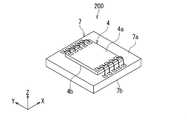
以下、本発明の実施の形態について図面を参照して詳細に説明する。始めに、本発明の第1の実施の形態に係る位置検出装置1が適用された関節機構300について説明する。関節機構300は、関節を含む機構である。図1は、関節機構300の概略の構成を示す斜視図である。図2は、関節機構300の概略の構成を示す断面図である。図3は、位置検出装置1における基準座標系を説明するための説明図である。図4は、本実施の形態に係る磁気センサシステムの構成を示す機能ブロック図である。[First Embodiment]
Hereinafter, embodiments of the present invention will be described in detail with reference to the drawings. First, the
図1および図2に示したように、関節機構300は、第1の部材310と、第2の部材320と、位置検出装置1を含んでいる。 As shown in FIGS. 1 and 2, the
第1の部材310は、軸部311と、この軸部311の長手方向の一端に連結された球状部312とを含んでいる。球状部312は、凸面312aを有している。凸面312aは、第1の球面の一部によって構成されている。第1の球面のうち、凸面312aに含まれない部分は、軸部311と球状部312の境界部分である。 The
第2の部材320は、軸部321と、この軸部321の長手方向の一端に連結された受け部322とを含んでいる。受け部322は、凹面322aを有している。凹面322aは、第2の球面の一部によって構成されている。凹面322aは、第2の球面のうちの半分または半分に近い部分によって構成されていてもよい。 The
第1の部材310と第2の部材320は、球状部312が受け部322に嵌り込んだ姿勢で、互いの位置関係が変化可能に連結されている。第2の球面の半径は、第1の球面の半径と等しいか、それよりもわずかに大きい。凸面312aと凹面322aは、接触していてもよいし、潤滑剤を介して対向していてもよい。第2の球面の中心は、第1の球面の中心と一致しているか、ほぼ一致している。第1の部材310と第2の部材320の連結部分が関節である。本実施の形態では特に、この関節は球関節である。 The
位置検出装置1は、磁界発生器2と磁気センサ装置4とを備えている。位置検出装置1は、更に、図4に示した、本実施の形態に係る信号処理回路5を備えている。図4に示したように、磁気センサ装置4と信号処理回路5は、本実施の形態に係る磁気センサシステム3を構成している。従って、位置検出装置1は、磁界発生器2と磁気センサシステム3とを備えていると言える。 The
磁界発生器2は、磁気センサ装置4に対する相対的な位置が所定の球面に沿って変化可能である。位置検出装置1は、磁気センサ装置4に対する磁界発生器2の相対的な位置を検出するための装置である。 The position of the
磁界発生器2は、所定の磁界を発生する。磁界発生器2は、例えば磁石である。磁気センサ装置4は、基準位置における磁界の互いに異なる3つの方向の成分と対応関係を有する第1の検出信号、第2の検出信号および第3の検出信号を生成する。基準位置については、後で詳しく説明する。 The
信号処理回路5は、第1ないし第3の検出信号を処理して、磁気センサ装置4に対する磁界発生器2の相対的な位置を表す位置情報を生成する。 The
図1および図2に示したように、磁界発生器2は、凹面322aから突出しないように受け部322に埋め込まれている。磁気センサ装置4は、球状部312の内部に配置されている。以下、第1の球面の中心の位置を基準位置と言う。磁気センサ装置4は、基準位置における磁界を検出するように構成されている。 As shown in FIGS. 1 and 2, the
以下、磁界発生器2によって発生された磁界のうちの基準位置における磁界を対象磁界と言う。対象磁界の方向は、例えば、基準位置と磁界発生器2とを通過する仮想の直線に平行である。図2に示した例では、磁界発生器2は、上記の仮想の直線に沿って並ぶN極とS極を有する磁石である。S極は、N極よりも基準位置により近い。図2に示した矢印付きの複数の破線は、磁界発生器2が発生する磁界に対応する磁力線を表している。 Hereinafter, the magnetic field at the reference position among the magnetic fields generated by the
図1および図2に示した関節機構300では、球状部312が受け部322に嵌り込んだ姿勢で、第1の部材310に対する第2の部材320の相対的位置が変化可能である。これにより、磁界発生器2は、磁気センサ装置4に対する相対的な位置が、前述の所定の球面に沿って変化可能である。本実施の形態では、磁気センサ装置4に対する磁界発生器2の相対的な位置を、磁界発生器2のうちの基準位置に最も近い点の位置とする。所定の球面の中心は、第1の球面の中心と一致しているか、ほぼ一致している。所定の球面の半径は、第1の球面の半径以上である。所定の球面の半径は、第1の球面の半径または第2の球面の半径と一致していてもよい。 In the
ここで、図3を参照して、本実施の形態における基準座標系について説明する。基準座標系は、磁気センサ装置4を基準とした座標系であって、第1ないし第3の検出信号の値を表すための3つの軸によって定義された直交座標系である。基準座標系では、X方向、Y方向、Z方向が定義されている。図3に示したように、X方向、Y方向、Z方向は、互いに直交する。また、X方向とは反対の方向を−X方向とし、Y方向とは反対の方向を−Y方向とし、Z方向とは反対の方向を−Z方向とする。 Here, the reference coordinate system in the present embodiment will be described with reference to FIG. The reference coordinate system is a coordinate system based on the
前述の通り、磁気センサ装置4は、基準位置における磁界の互いに異なる3つの方向の成分と対応関係を有する第1の検出信号、第2の検出信号および第3の検出信号を生成する。本実施の形態では特に、上記の互いに異なる3つの方向は、X方向に平行な方向と、Y方向に平行な方向と、Z方向に平行な方向である。基準座標系を定義する3つの軸は、X方向に平行な軸と、Y方向に平行な軸と、Z方向に平行な軸である。 As described above, the
基準座標系における磁気センサ装置4の位置は変化しない。磁気センサ装置4に対する磁界発生器2の相対的な位置が変化すると、基準座標系における磁界発生器2の位置は、前述の所定の球面に沿って変化する。図3において、符号9は、所定の球面を示している。基準座標系における磁界発生器2の位置は、磁気センサ装置4に対する磁界発生器2の相対的な位置を表している。以下、基準座標系における磁界発生器2の位置を、単に磁界発生器2の位置と言う。また、基準位置を含むXY平面を基準平面と言う。 The position of the
位置検出装置1を含む関節機構300では、位置検出装置1によって、磁気センサ装置4に対する磁界発生器2の相対的な位置を検出することによって、第1の部材310に対する第2の部材320の相対的位置を検出することができる。関節機構300は、ロボット、産業機器、医療機器、アミューズメント機器等に利用される。 In the
位置検出装置1は、関節機構300の他に、ジョイスティックや、トラックボールにも適用することができる。 The
ジョイスティックは、例えば、レバーと、このレバーを揺動可能に支持する支持部とを含んでいる。位置検出装置1を、ジョイスティックに適用する場合には、例えば、レバーの揺動に伴って、磁気センサ装置4に対する磁界発生器2の相対的な位置が所定の球面に沿って変化するように、支持部の内部に磁界発生器2を設け、レバーの内部に磁気センサ装置4を設ける。 The joystick includes, for example, a lever and a support that swingably supports the lever. When the
トラックボールは、例えば、ボールと、このボールを回転可能に支持する支持部とを含んでいる。位置検出装置1を、トラックボールに適用する場合には、例えば、ボールの回転に伴って、磁気センサ装置4に対する磁界発生器2の相対的な位置が所定の球面に沿って変化するように、支持部の内部に磁界発生器2を設け、ボールの内部に磁気センサ装置4を設ける。 The trackball includes, for example, a ball and a support that rotatably supports the ball. When the
次に、図4を参照して、磁気センサ装置4と信号処理回路5の構成について説明する。磁気センサ装置4は、対象磁界の互いに異なる3つの方向の成分と対応関係を有する第1の検出信号Sx、第2の検出信号Syおよび第3の検出信号Szを生成する。本実施の形態では、第1の検出信号Sxは、対象磁界の、第1の感磁方向の成分である第1の成分と対応関係を有する。第2の検出信号Syは、対象磁界の、第2の感磁方向の成分である第2の成分と対応関係を有する。第3の検出信号Szは、対象磁界の、第3の感磁方向の成分である第3の成分と対応関係を有する。 Next, the configuration of the
本実施の形態では、磁気センサ装置4は、第1の検出信号Sxを生成する第1の磁気センサ10と、第2の検出信号Syを生成する第2の磁気センサ20と、第3の検出信号Szを生成する第3の磁気センサ30とを備えている。第1ないし第3の磁気センサ10,20,30の各々は、少なくとも1つの磁気検出素子を含んでいる。 In the present embodiment, the
信号処理回路5は、第1のプロセッサ7と第2のプロセッサ8とを備えている。本実施の形態では、第1のプロセッサ7を構成するハードウェアは、第2のプロセッサ8を構成するハードウェアとは異なっている。第1のプロセッサ7は、例えば特定用途向け集積回路(ASIC)によって構成されている。第2のプロセッサ8は、例えばマイクロコンピュータによって構成されている。 The
次に、磁気センサ装置4と第1のプロセッサ7の構成について説明する。本実施の形態では、磁気センサ装置4は、第1のチップの形態を有している。また、第1のプロセッサ7は、第1のチップとは異なる第2のチップの形態を有している。第1のプロセッサ7は、磁気センサ装置4と一体化されていてもよい。第2のプロセッサ8は、磁気センサ装置4および第1のプロセッサ7とは別体であってもよい。本実施の形態では、一体化された磁気センサ装置4および第1のプロセッサ7を、磁気センサ組立体200と言う。 Next, the configuration of the
図5は、磁気センサ組立体200を示す斜視図である。図5に示したように、磁気センサ装置4および第1のプロセッサ7は、いずれも直方体形状を有している。また、磁気センサ装置4および第1のプロセッサ7は、いずれも外面を有している。 FIG. 5 is a perspective view showing the
磁気センサ装置4の外面は、互いに反対側に位置する上面4aおよび下面4bと、上面4aと下面4bを接続する4つの側面を含んでいる。第1のプロセッサ7の外面は、互いに反対側に位置する上面7aおよび下面7bと、上面7aと下面7bを接続する4つの側面を含んでいる。磁気センサ装置4は、下面4bが第1のプロセッサ7の上面7aに対向する姿勢で、上面7a上に実装されている。 The outer surface of the
磁気センサ装置4は、上面4aに設けられた端子群を備えている。第1のプロセッサ7は、上面7aに設けられた端子群を備えている。磁気センサ装置4の端子群は、例えば複数のボンディングワイヤによって、第1のプロセッサ7の端子群に接続されている。 The
次に、図6を参照して、第1ないし第3の磁気センサ10,20,30の配置について説明する。図6は、磁気センサ装置4を示す平面図である。図6に示したように、磁気センサ装置4は、前述の第1ないし第3の磁気センサ10,20,30と、第1ないし第3の磁気センサ10,20,30を支持する基板51と、端子群とを備えている。基板51は、上面51aと下面51bを有している。なお、下面51bは、後で説明する図12に示されている。 Next, the arrangement of the first to third
ここで、図6を参照して、基準座標系および基準平面と磁気センサ装置4の構成要素との関係について説明する。前述のように、基準座標系では、X方向、Y方向、Z方向、−X方向、−Y方向、−Z方向が定義されている。X方向とY方向は基板51の上面51aに平行な方向である。Z方向は、基板51の上面51aに垂直な方向であって、基板51の下面51bから上面51aに向かう方向である。以下、基準の位置に対してZ方向の先にある位置を「上方」と言い、基準の位置に対して「上方」とは反対側にある位置を「下方」と言う。また、磁気センサ装置4の構成要素に関して、Z方向の端に位置する面を「上面」と言い、−Z方向の端に位置する面を「下面」と言う。 Here, with reference to FIG. 6, the relationship between the reference coordinate system and the reference plane and the components of the
本実施の形態では、基板51の上面51aが基準平面である。以下、基準平面を記号RPで表す。基準平面RPは、互いに異なる第1の領域A10と第2の領域A20と第3の領域A30を含んでいる。第1の領域A10は、基準平面RPに第1の磁気センサ10を垂直投影してできる領域である。第2の領域A20は、基準平面RPに第2の磁気センサ20を垂直投影してできる領域である。第3の領域A30は、基準平面RPに第3の磁気センサ30を垂直投影してできる領域である。 In the present embodiment, the
ここで、基準平面RP内に位置して、第3の領域A30の重心C30を通り、Z方向に垂直で且つ互いに直交する2つの直線を第1の直線L1と第2の直線L2とする。本実施の形態では特に、第1の直線L1はX方向に平行であり、第2の直線L2はY方向に平行である。 Here, two straight lines that are located in the reference plane RP, pass through the center of gravity C30 of the third region A30, are perpendicular to the Z direction, and are orthogonal to each other are referred to as a first straight line L1 and a second straight line L2. In this embodiment, in particular, the first straight line L1 is parallel to the X direction and the second straight line L2 is parallel to the Y direction.
本実施の形態では、第1の磁気センサ10は、X方向の互いに異なる位置に配置された第1の部分11と第2の部分12を含んでいる。第1の領域A10は、基準平面RPに第1の磁気センサ10の第1の部分11を垂直投影してできる第1の部分領域A11と、基準平面RPに第1の磁気センサ10の第2の部分12を垂直投影してできる第2の部分領域A12を含んでいる。第1および第2の部分領域A11,A12は、第1の直線L1に平行な方向における第3の領域A30の両側に位置している。 In the present embodiment, the first
また、第2の磁気センサ20は、Y方向の互いに異なる位置に配置された第1の部分21と第2の部分22を含んでいる。第2の領域A20は、基準平面RPに第2の磁気センサ20の第1の部分21を垂直投影してできる第3の部分領域A21と、基準平面RPに第2の磁気センサ20の第2の部分22を垂直投影してできる第4の部分領域A22を含んでいる。第3および第4の部分領域A21,A22は、第2の直線L2に平行な方向における第3の領域A30の両側に位置している。 Further, the second
本実施の形態では、第1および第2の部分領域A11,A12は、いずれも第1の直線L1と交差する位置にある。また、第3および第4の部分領域A21,A22は、いずれも第2の直線L2と交差する位置にある。 In the present embodiment, the first and second partial regions A11 and A12 are both located at positions intersecting the first straight line L1. Further, the third and fourth partial regions A21 and A22 are both located at positions intersecting with the second straight line L2.
第1の領域A10のいかなる部分も第2の直線L2とは交差しないことが好ましい。同様に、第2の領域A20のいかなる部分も第1の直線L1とは交差しないことが好ましい。 It is preferable that no portion of the first region A10 intersects the second straight line L2. Similarly, it is preferable that no portion of the second region A20 intersects the first straight line L1.
本実施の形態では特に、第1の領域A10と第2の領域A20は、上方から見て、第3の領域A30の重心C30を中心として第1の領域A10を90°回転すると第2の領域A20に重なる位置関係である。図6において、重心C30を中心として反時計回り方向に第1および第2の部分領域A11,A12を90°回転すると、第1および第2の部分領域A11,A12はそれぞれ第3および第4の部分領域A21,A22に重なる。 In particular, in the present embodiment, the first region A10 and the second region A20 are the second regions when the first region A10 is rotated by 90 ° about the center of gravity C30 of the third region A30 when viewed from above. It is a positional relationship that overlaps with A20. In FIG. 6, when the first and second subregions A11 and A12 are rotated by 90 ° in the counterclockwise direction about the center of gravity C30, the first and second subregions A11 and A12 become the third and fourth subregions, respectively. It overlaps the partial regions A21 and A22.
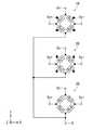
次に、図7および図8を参照して、磁気センサ装置4の構成の一例について説明する。図7は、磁気センサ装置4の構成を示す説明図である。図8は、磁気センサ装置4の回路構成の一例を示す回路図である。 Next, an example of the configuration of the
前述のように、第1の磁気センサ10は、対象磁界の、第1の感磁方向の成分である第1の成分と対応関係を有する第1の検出信号Sxを生成する。第2の磁気センサ20は、対象磁界の、第2の感磁方向の成分である第2の成分と対応関係を有する第2の検出信号Syを生成する。第3の磁気センサ30は、対象磁界の、第3の感磁方向の成分である第3の成分と対応関係を有する第3の検出信号Szを生成する。 As described above, the first
本実施の形態では特に、第1の感磁方向は、X方向に平行な方向である。第1の感磁方向は、X方向と−X方向とを含む。第2の感磁方向は、Y方向に平行な方向である。第2の感磁方向は、Y方向と−Y方向とを含む。第3の感磁方向は、Z方向に平行な方向である。第3の感磁方向は、Z方向と−Z方向とを含む。 In this embodiment, in particular, the first magnetic sensitivity direction is a direction parallel to the X direction. The first magnetic sensing direction includes the X direction and the −X direction. The second magnetic sensing direction is a direction parallel to the Y direction. The second magnetic sensing direction includes the Y direction and the −Y direction. The third magnetic sensing direction is a direction parallel to the Z direction. The third magnetic sensing direction includes the Z direction and the −Z direction.
また、図7に示したように、磁気センサ装置4の端子群は、第1の磁気センサ10に対応する電源端子Vxおよび出力端子Vx+,Vx−と、第2の磁気センサ20に対応する電源端子Vyおよび出力端子Vy+,Vy−と、第3の磁気センサ30に対応する電源端子Vzおよび出力端子Vz+,Vz−と、第1ないし第3の磁気センサ10,20,30で共通に使用されるグランド端子Gとを含んでいる。 Further, as shown in FIG. 7, the terminal group of the
図8に示した例では、第1の磁気センサ10は、ホイートストンブリッジ回路を構成する4つの抵抗部Rx1,Rx2,Rx3,Rx4を含んでいる。抵抗部Rx1,Rx2,Rx3,Rx4の各々は、対象磁界の第1の成分に応じて変化する抵抗値を有する。抵抗部Rx1は、電源端子Vxと出力端子Vx+との間に設けられている。抵抗部Rx2は、出力端子Vx+とグランド端子Gとの間に設けられている。抵抗部Rx3は、電源端子Vxと出力端子Vx−との間に設けられている。抵抗部Rx4は、出力端子Vx−とグランド端子Gとの間に設けられている。 In the example shown in FIG. 8, the first
第2の磁気センサ20は、ホイートストンブリッジ回路を構成する4つの抵抗部Ry1,Ry2,Ry3,Ry4を含んでいる。抵抗部Ry1,Ry2,Ry3,Ry4の各々は、対象磁界の第2の成分に応じて変化する抵抗値を有する。抵抗部Ry1は、電源端子Vyと出力端子Vy+との間に設けられている。抵抗部Ry2は、出力端子Vy+とグランド端子Gとの間に設けられている。抵抗部Ry3は、電源端子Vyと出力端子Vy−との間に設けられている。抵抗部Ry4は、出力端子Vy−とグランド端子Gとの間に設けられている。 The second
第3の磁気センサ30は、ホイートストンブリッジ回路を構成する4つの抵抗部Rz1,Rz2,Rz3,Rz4を含んでいる。抵抗部Rz1,Rz2,Rz3,Rz4の各々は、後述する磁界変換部から出力される出力磁界成分に応じて変化する抵抗値を有する。抵抗部Rz1は、電源端子Vzと出力端子Vz+との間に設けられている。抵抗部Rz2は、出力端子Vz+とグランド端子Gとの間に設けられている。抵抗部Rz3は、電源端子Vzと出力端子Vz−との間に設けられている。抵抗部Rz4は、出力端子Vz−とグランド端子Gとの間に設けられている。 The third
以下、抵抗部Rx1,Rx2,Rx3,Rx4,Ry1,Ry2,Ry3,Ry4,Rz1,Rz2,Rz3,Rz4のうちの任意の1つを抵抗部Rと言う。抵抗部Rは、少なくとも1つの磁気検出素子を含んでいる。本実施の形態では特に、少なくとも1つの磁気検出素子は、少なくとも1つの磁気抵抗効果素子である。以下、磁気抵抗効果素子をMR素子と記す。 Hereinafter, any one of the resistance portions Rx1, Rx2, Rx3, Rx4, Ry1, Ry2, Ry3, Ry4, Rz1, Rz2, Rz3, and Rz4 will be referred to as a resistance portion R. The resistance portion R includes at least one magnetic detection element. In particular, in this embodiment, at least one magnetic detector is at least one magnetoresistive sensor. Hereinafter, the magnetoresistive element will be referred to as an MR element.
本実施の形態では特に、MR素子は、スピンバルブ型のMR素子である。このスピンバルブ型のMR素子は、方向が固定された磁化を有する磁化固定層と、印加磁界の方向に応じて方向が変化可能な磁化を有する自由層と、磁化固定層と自由層の間に配置されたギャップ層とを有している。スピンバルブ型のMR素子は、TMR(トンネル磁気抵抗効果)素子でもよいし、GMR(巨大磁気抵抗効果)素子でもよい。TMR素子では、ギャップ層はトンネルバリア層である。GMR素子では、ギャップ層は非磁性導電層である。スピンバルブ型のMR素子では、自由層の磁化の方向が磁化固定層の磁化の方向に対してなす角度に応じて抵抗値が変化し、この角度が0°のときに抵抗値は最小値となり、角度が180°のときに抵抗値は最大値となる。各MR素子において、自由層は、磁化容易軸方向が、磁化固定層の磁化の方向に直交する方向となる形状異方性を有している。 In this embodiment, the MR element is a spin valve type MR element. This spin valve type MR element has a magnetization fixed layer having a fixed direction magnetization, a free layer having a magnetization whose direction can be changed according to the direction of an applied magnetic field, and a magnetization fixed layer and a free layer. It has an arranged gap layer. The spin valve type MR element may be a TMR (tunnel magnetoresistive effect) element or a GMR (giant magnetoresistive effect) element. In the TMR element, the gap layer is a tunnel barrier layer. In the GMR element, the gap layer is a non-magnetic conductive layer. In a spin valve type MR element, the resistance value changes according to the angle formed by the magnetization direction of the free layer with respect to the magnetization direction of the magnetization fixed layer, and when this angle is 0 °, the resistance value becomes the minimum value. , The resistance value becomes the maximum value when the angle is 180 °. In each MR element, the free layer has a shape anisotropy in which the axial direction of easy magnetization is orthogonal to the direction of magnetization of the fixed magnetization layer.
図8において、塗りつぶした矢印は、MR素子における磁化固定層の磁化の方向を表している。図8に示した例では、抵抗部Rx1,Rx4の各々におけるMR素子の磁化固定層の磁化の方向は、X方向である。抵抗部Rx2,Rx3の各々におけるMR素子の磁化固定層の磁化の方向は、−X方向である。 In FIG. 8, the filled arrow indicates the direction of magnetization of the magnetization fixed layer in the MR element. In the example shown in FIG. 8, the magnetization direction of the magnetization fixed layer of the MR element in each of the resistance portions Rx1 and Rx4 is the X direction. The magnetization direction of the magnetization fixed layer of the MR element in each of the resistance portions Rx2 and Rx3 is the −X direction.
また、抵抗部Ry1,Ry4の各々におけるMR素子の磁化固定層の磁化の方向は、Y方向である。抵抗部Ry2,Ry3の各々におけるMR素子の磁化固定層の磁化の方向は、−Y方向である。抵抗部Rz1,Rz2,Rz3,Rz4の各々におけるMR素子の磁化固定層の磁化の方向については、後で説明する。 Further, the magnetization direction of the magnetization fixed layer of the MR element in each of the resistance portions Ry1 and Ry4 is the Y direction. The magnetization direction of the magnetization fixed layer of the MR element in each of the resistance portions Ry2 and Ry3 is the −Y direction. The direction of magnetization of the magnetization fixed layer of the MR element in each of the resistance portions Rz1, Rz2, Rz3, and Rz4 will be described later.
出力端子Vx+と出力端子Vx−との間の電位差は、対象磁界の第1の成分と対応関係を有する。第1の磁気センサ10は、出力端子Vx+と出力端子Vx−との間の電位差に対応する第1の検出信号Sxを生成する。第1の検出信号Sxは、出力端子Vx+と出力端子Vx−との間の電位差に対して振幅やオフセットの調整を施したものであってもよい。 The potential difference between the output terminal Vx + and the output terminal Vx− has a corresponding relationship with the first component of the target magnetic field. The first
出力端子Vy+と出力端子Vy−との間の電位差は、対象磁界の第2の成分と対応関係を有する。第2の磁気センサ20は、出力端子Vy+と出力端子Vy−との間の電位差に対応する第2の検出信号Syを生成する。第2の検出信号Syは、出力端子Vy+と出力端子Vy−との間の電位差に対して振幅やオフセットの調整を施したものであってもよい。 The potential difference between the output terminal Vy + and the output terminal Vy− has a corresponding relationship with the second component of the target magnetic field. The second
出力端子Vz+と出力端子Vz−との間の電位差は、対象磁界の第3の成分と対応関係を有する。第3の磁気センサ30は、出力端子Vz+と出力端子Vz−との間の電位差に対応する第3の検出信号Szを生成する。第3の検出信号Szは、出力端子Vz+と出力端子Vz−との間の電位差に対して振幅やオフセットの調整を施したものであってもよい。 The potential difference between the output terminal Vz + and the output terminal Vz− has a corresponding relationship with the third component of the target magnetic field. The third
ここで、図7を参照して、抵抗部Rx1,Rx2,Rx3,Rx4,Ry1,Ry2,Ry3,Ry4の配置の一例について説明する。この例では、第1の磁気センサ10の第1の部分11は抵抗部Rx1,Rx4を含み、第1の磁気センサ10の第2の部分12は抵抗部Rx2,Rx3を含んでいる。また、第2の磁気センサ20の第1の部分21は抵抗部Ry1,Ry4を含み、第2の磁気センサ20の第2の部分22は抵抗部Ry2,Ry3を含んでいる。 Here, an example of the arrangement of the resistance portions Rx1, Rx2, Rx3, Rx4, Ry1, Ry2, Ry3, and Ry4 will be described with reference to FIG. 7. In this example, the
図7において、塗りつぶした矢印は、MR素子における磁化固定層の磁化の方向を表している。図7に示した例では、第1の磁気センサ10の第1の部分11と、第1の磁気センサ10の第2の部分12と、第2の磁気センサ20の第1の部分21と、第2の磁気センサ20の第2の部分22の各々において、そこに含まれる複数のMR素子の磁化固定層の磁化の方向が同じ方向になる。そのため、この例によれば、複数のMR素子の磁化固定層の磁化の方向の設定が容易になる。 In FIG. 7, the filled arrow indicates the direction of magnetization of the magnetization fixed layer in the MR element. In the example shown in FIG. 7, the
次に、図9を参照して、MR素子の構成の一例について説明する。図9に示したMR素子100は、基板51側から順に積層された反強磁性層101、磁化固定層102、ギャップ層103および自由層104を含んでいる。反強磁性層101は、反強磁性材料よりなり、磁化固定層102との間で交換結合を生じさせて、磁化固定層102の磁化の方向を固定する。 Next, an example of the configuration of the MR element will be described with reference to FIG. The
なお、MR素子100における層101〜104の配置は、図9に示した配置とは上下が反対でもよい。また、磁化固定層102は、単一の強磁性層ではなく、2つの強磁性層とこの2つの強磁性層の間に配置された非磁性金属層とを含む人工反強磁性構造であってもよい。また、MR素子100は、反強磁性層101を含まない構成であってもよい。また、磁気検出素子は、ホール素子、磁気インピーダンス素子等、MR素子以外の磁界を検出する素子であってもよい。 The arrangement of the
次に、図10を参照して、抵抗部Rの構成の一例について説明する。この例では、抵抗部Rは、直列に接続された複数のMR素子100を含んでいる。抵抗部Rは、更に、複数のMR素子100が直列に接続されるように、回路構成上隣接する2つのMR素子100を電気的に接続する1つ以上の接続層を含んでいる。図10に示した例では、抵抗部Rは、1つ以上の接続層として、1つ以上の下部接続層111と、1つ以上の上部接続層112とを含んでいる。下部接続層111は、回路構成上隣接する2つのMR素子100の下面に接し、この2つのMR素子100を電気的に接続する。上部接続層112は、回路構成上隣接する2つのMR素子100の上面に接し、この2つのMR素子100を電気的に接続する。 Next, an example of the configuration of the resistance portion R will be described with reference to FIG. In this example, the resistor portion R includes a plurality of
次に、図11を参照して、第3の磁気センサ30の構成の一例について説明する。第3の磁気センサ30は、抵抗部Rz1,Rz2,Rz3,Rz4の他に、軟磁性材料よりなる軟磁性構造体40を含んでいる。軟磁性構造体40は、磁界変換部42と、少なくとも1つの軟磁性層を含んでいる。磁界変換部42は、対象磁界の第3の成分を受けて第3の感磁方向に垂直な方向の出力磁界成分を出力する。出力磁界成分の強度は、対象磁界の第3の成分の強度と対応関係を有する。第3の磁気センサ30は、出力磁界成分の強度を検出することによって、対象磁界の第3の成分の強度を検出する。 Next, an example of the configuration of the third
図11に示した例では、磁界変換部42は、抵抗部Rz1に対応する下部ヨーク42B1および上部ヨーク42T1と、抵抗部Rz2に対応する下部ヨーク42B2および上部ヨーク42T2と、抵抗部Rz3に対応する下部ヨーク42B3および上部ヨーク42T3と、抵抗部Rz4に対応する下部ヨーク42B4および上部ヨーク42T4とを含んでいる。 In the example shown in FIG. 11, the magnetic
下部ヨーク42B1,42B2,42B3,42B4および上部ヨーク42T1,42T2,42T3,42T4の各々は、Z方向に垂直な方向に長い直方体形状を有している。 Each of the lower yokes 42B1, 42B2, 42B3, 42B4 and the upper yokes 42T1, 42T2, 42T3, 42T4 has a rectangular parallelepiped shape that is long in the direction perpendicular to the Z direction.
下部ヨーク42B1および上部ヨーク42T1は、抵抗部Rz1の近傍に配置されている。下部ヨーク42B1は、抵抗部Rz1よりも、基板51の上面51aにより近い位置に配置されている。上部ヨーク42T1は、抵抗部Rz1よりも、基板51の上面51aからより遠い位置に配置されている。上方から見たときに、抵抗部Rz1は、下部ヨーク42B1と上部ヨーク42T1の間に位置している。 The lower yoke 42B1 and the upper yoke 42T1 are arranged in the vicinity of the resistance portion Rz1. The lower yoke 42B1 is arranged at a position closer to the
下部ヨーク42B2および上部ヨーク42T2は、抵抗部Rz2の近傍に配置されている。下部ヨーク42B2は、抵抗部Rz2よりも、基板51の上面51aにより近い位置に配置されている。上部ヨーク42T2は、抵抗部Rz2よりも、基板51の上面51aからより遠い位置に配置されている。上方から見たときに、抵抗部Rz2は、下部ヨーク42B2と上部ヨーク42T2の間に位置している。 The lower yoke 42B2 and the upper yoke 42T2 are arranged in the vicinity of the resistance portion Rz2. The lower yoke 42B2 is arranged at a position closer to the
下部ヨーク42B3および上部ヨーク42T3は、抵抗部Rz3の近傍に配置されている。下部ヨーク42B3は、抵抗部Rz3よりも、基板51の上面51aにより近い位置に配置されている。上部ヨーク42T3は、抵抗部Rz3よりも、基板51の上面51aからより遠い位置に配置されている。上方から見たときに、抵抗部Rz3は、下部ヨーク42B3と上部ヨーク42T3の間に位置している。 The lower yoke 42B3 and the upper yoke 42T3 are arranged in the vicinity of the resistance portion Rz3. The lower yoke 42B3 is arranged at a position closer to the
下部ヨーク42B4および上部ヨーク42T4は、抵抗部Rz4の近傍に配置されている。下部ヨーク42B4は、抵抗部Rz4よりも、基板51の上面51aにより近い位置に配置されている。上部ヨーク42T4は、抵抗部Rz4よりも、基板51の上面51aからより遠い位置に配置されている。上方から見たときに、抵抗部Rz4は、下部ヨーク42B4と上部ヨーク42T4の間に位置している。 The lower yoke 42B4 and the upper yoke 42T4 are arranged in the vicinity of the resistance portion Rz4. The lower yoke 42B4 is arranged at a position closer to the
磁界変換部42が出力する出力磁界成分は、下部ヨーク42B1および上部ヨーク42T1によって生成されて抵抗部Rz1に印加される磁界成分と、下部ヨーク42B2および上部ヨーク42T2によって生成されて抵抗部Rz2に印加される磁界成分と、下部ヨーク42B3および上部ヨーク42T3によって生成されて抵抗部Rz3に印加される磁界成分と、下部ヨーク42B4および上部ヨーク42T4によって生成されて抵抗部Rz4に印加される磁界成分を含んでいる。 The output magnetic field component output by the magnetic
図11において、4つの白抜きの矢印は、それぞれ、対象磁界の第3の成分の方向がZ方向であるときに、抵抗部Rz1,Rz2,Rz3,Rz4に印加される磁界成分の方向を表している。また、図11において、4つの塗りつぶした矢印は、それぞれ、抵抗部Rz1,Rz2,Rz3,Rz4のMR素子100の磁化固定層102の磁化の方向を表している。抵抗部Rz1,Rz4のMR素子100の磁化固定層102の磁化の方向は、それぞれ、対象磁界の第3の成分の方向がZ方向であるときに抵抗部Rz1,Rz4に印加される磁界成分の方向と同じ方向である。抵抗部Rz2,Rz3のMR素子100の磁化固定層102の磁化の方向は、それぞれ、対象磁界の第3の成分の方向がZ方向であるときに抵抗部Rz2,Rz3に印加される磁界成分の方向とは反対方向である。 In FIG. 11, the four white arrows represent the directions of the magnetic field components applied to the resistance portions Rz1, Rz2, Rz3, and Rz4 when the direction of the third component of the target magnetic field is the Z direction, respectively. ing. Further, in FIG. 11, the four filled arrows represent the magnetization directions of the magnetization fixed
ここで、第3の磁気センサ30の作用について説明する。対象磁界の第3の成分が存在しない状態では、抵抗部Rz1,Rz2,Rz3,Rz4のMR素子100の自由層104の磁化の方向は、磁化固定層102の磁化の方向に対して垂直である。 Here, the operation of the third
対象磁界の第3の成分の方向がZ方向であるときには、抵抗部Rz1,Rz4のMR素子100では、自由層104の磁化の方向は、磁化固定層102の磁化の方向に対して垂直な方向から、磁化固定層102の磁化の方向に向かって傾く。このとき、抵抗部Rz2,Rz3のMR素子100では、自由層104の磁化の方向は、磁化固定層102の磁化の方向に対して垂直な方向から、磁化固定層102の磁化の方向とは反対方向に向かって傾く。その結果、対象磁界の第3の成分が存在しない状態と比べて、抵抗部Rz1,Rz4の抵抗値は減少し、抵抗部Rz2,Rz3の抵抗値は増加する。 When the direction of the third component of the target magnetic field is the Z direction, in the
対象磁界の第3の成分の方向が−Z方向の場合は、上述の場合とは逆に、対象磁界の第3の成分が存在しない状態と比べて、抵抗部Rz1,Rz4の抵抗値は増加し、抵抗部Rz2,Rz3の抵抗値は減少する。 When the direction of the third component of the target magnetic field is the −Z direction, contrary to the above case, the resistance values of the resistance portions Rz1 and Rz4 increase as compared with the state where the third component of the target magnetic field does not exist. However, the resistance values of the resistance portions Rz2 and Rz3 decrease.
抵抗部Rz1,Rz2,Rz3,Rz4の抵抗値の変化量は、第3の成分の強度に依存する。 The amount of change in the resistance value of the resistance portions Rz1, Rz2, Rz3, and Rz4 depends on the intensity of the third component.
対象磁界の第3の成分の方向と強度が変化すると、抵抗部Rz1,Rz2,Rz3,Rz4のそれぞれの抵抗値は、抵抗部Rz1,Rz4の抵抗値が増加すると共に抵抗部Rz2,Rz3の抵抗値が減少するか、抵抗部Rz1,Rz4の抵抗値が減少すると共に抵抗部Rz2,Rz3の抵抗値が増加するように変化する。これにより、出力端子Vz+と出力端子Vz−との間の電位差が変化する。従って、この電位差に基づいて、対象磁界の第3の成分を検出することができる。第3の磁気センサ30は、出力端子Vz+と出力端子Vz−との間の電位差に対応する第3の検出信号Szを生成する。第3の検出信号Szは、出力端子Vz+と出力端子Vz−との間の電位差に対して振幅やオフセットの調整を施したものであってもよい。 When the direction and intensity of the third component of the target magnetic field change, the resistance values of the resistance portions Rz1, Rz2, Rz3, and Rz4 increase as the resistance values of the resistance portions Rz1 and Rz4 increase, and the resistances of the resistance portions Rz2 and Rz3 increase. The value decreases, or the resistance values of the resistance portions Rz1 and Rz4 decrease and the resistance values of the resistance portions Rz2 and Rz3 increase. As a result, the potential difference between the output terminal Vz + and the output terminal Vz− changes. Therefore, the third component of the target magnetic field can be detected based on this potential difference. The third
次に、図12を参照して、第1ないし第3の磁気センサ10,20,30の構造の一例について説明する。図12は、第1ないし第3の磁気センサ10,20,30のそれぞれの一部を示している。この例では、第1ないし第3の磁気センサ10,20,30は、基板51の上に配置されている。基板51は、上面51aと下面51bを有している。 Next, an example of the structure of the first to third
第1の磁気センサ10は、抵抗部Rx1,Rx2,Rx3,Rx4の他に、それぞれ絶縁材料よりなる絶縁層66A,67A,68Aを含んでいる。絶縁層66Aは、基板51の上面51aの上に配置されている。抵抗部Rx1,Rx2,Rx3,Rx4は、絶縁層66Aの上に配置されている。図12には、抵抗部Rx1,Rx2,Rx3,Rx4に含まれる複数のMR素子100のうちの1つと、それに接続された下部接続層111および上部接続層112を示している。絶縁層67Aは、絶縁層66Aの上面の上において抵抗部Rx1,Rx2,Rx3,Rx4の周囲に配置されている。絶縁層68Aは、抵抗部Rx1,Rx2,Rx3,Rx4および絶縁層67Aを覆っている。 The first
第2の磁気センサ20の構造は、第1の磁気センサ10と同様である。すなわち、第2の磁気センサ20は、抵抗部Ry1,Ry2,Ry3,Ry4の他に、それぞれ絶縁材料よりなる絶縁層66B,67B,68Bを含んでいる。絶縁層66Bは、基板51の上面51aの上に配置されている。抵抗部Ry1,Ry2,Ry3,Ry4は、絶縁層66Bの上に配置されている。図12には、抵抗部Ry1,Ry2,Ry3,Ry4に含まれる複数のMR素子100のうちの1つと、それに接続された下部接続層111および上部接続層112を示している。絶縁層67Bは、絶縁層66Bの上面の上において抵抗部Ry1,Ry2,Ry3,Ry4の周囲に配置されている。絶縁層68Bは、抵抗部Ry1,Ry2,Ry3,Ry4および絶縁層67Bを覆っている。 The structure of the second
第3の磁気センサ30は、抵抗部Rz1,Rz2,Rz3,Rz4および軟磁性構造体40の他に、それぞれ絶縁材料よりなる絶縁層61,62,63,64を含んでいる。図12に示した例では、軟磁性構造体40は、磁界変換部42と、2つの軟磁性層41,43を含んでいる。 The third
磁界変換部42は、図11に示した下部ヨーク42B1,42B2,42B3,42B4および上部ヨーク42T1,42T2,42T3,42T4を含んでいる。図12では、下部ヨーク42B1,42B2,42B3,42B4のうちの1つを符号42Bで示し、それに対応する上部ヨーク42T1,42T2,42T3,42T4のうちの1つを符号42Tで示している。 The magnetic
軟磁性層41は、基板51の上面51aの上に配置されている。下部ヨーク42B1,42B2,42B3,42B4は、軟磁性層41の上に配置されている。絶縁層61は、軟磁性層41の上において下部ヨーク42B1,42B2,42B3,42B4の周囲に配置されている。 The soft
抵抗部Rz1,Rz2,Rz3,Rz4は、絶縁層61の上に配置されている。図12には、抵抗部Rz1,Rz2,Rz3,Rz4に含まれる複数のMR素子100のうちの1つと、それに接続された下部接続層111および上部接続層112を示している。絶縁層62は、下部ヨーク42B1,42B2,42B3,42B4および絶縁層61の上において抵抗部Rz1,Rz2,Rz3,Rz4の周囲に配置されている。 The resistance portions Rz1, Rz2, Rz3, and Rz4 are arranged on the insulating
上部ヨーク42T1,42T2,42T3,42T4は、絶縁層62の上に配置されている。絶縁層63は、抵抗部Rz1,Rz2,Rz3,Rz4および絶縁層62の上において上部ヨーク42T1,42T2,42T3,42T4の周囲に配置されている。 The upper yokes 42T1, 42T2, 42T3, 42T4 are arranged on the insulating
軟磁性層43は、上部ヨーク42T1,42T2,42T3,42T4および絶縁層63の上に配置されている。絶縁層64は、軟磁性層43を覆っている。 The soft
上方から見たときに、軟磁性層41,43は、第3の磁気センサ30の全域またはほぼ全域にわたって存在する。言い換えると、基準平面RPに軟磁性層41を垂直投影してできる領域と、基準平面RPに軟磁性層43を垂直投影してできる領域は、いずれも、第3の領域A30と一致するかほぼ一致する。 When viewed from above, the soft
図12に示した例では、第1ないし第3の磁気センサ10,20,30に含まれる全ての磁気検出素子すなわちMR素子100は、基板51の上面51aすなわち基準平面RPから等しい距離の位置に配置されている。 In the example shown in FIG. 12, all the magnetic detection elements, that is,
なお、磁界変換部42は、下部ヨーク42B1,42B2,42B3,42B4と、上部ヨーク42T1,42T2,42T3,42T4の一方のみを含んでいてもよい。また、軟磁性構造体40は、軟磁性層41,43の一方のみを含んでいてもよい。 The magnetic
次に、図4を参照して、信号処理回路5が行う処理の内容と信号処理回路5の構成について説明する。信号処理回路5は、第1の処理と、第2の処理と、オフセット変化検出処理と、球体情報生成処理と、オフセット補正処理と、位置情報生成処理とを行う。前述の通り、信号処理回路5は第1のプロセッサ7と第2のプロセッサ8とを備えている。第1のプロセッサ7は、アナログ−デジタル変換器(以下、A/D変換器と記す。)70A,70B,70Cと、第1の処理を行う最大線分抽出部71と、第2の処理を行う中点座標演算部72と、オフセット変化検出処理を行うオフセット変化検出部73とを含んでいる。第2のプロセッサ8は、オフセット補正処理を行うオフセット補正部81と、球体情報生成処理を行う球体情報生成部82と、位置情報生成処理を行う位置情報生成部84とを含んでいる。 Next, with reference to FIG. 4, the contents of the processing performed by the
最大線分抽出部71、中点座標演算部72、オフセット変化検出部73、オフセット補正部81、球体情報生成部82および位置情報生成部84は、それぞれ上述の処理を行う機能ブロックである。 The maximum line
A/D変換器70A,70B,70Cは、それぞれ、第1ないし第3の検出信号Sx,Sy,Szをデジタル信号に変換する。デジタル信号に変換された第1ないし第3の検出信号Sx,Sy,Szは、最大線分抽出部71、オフセット変化検出部73、オフセット補正部81および球体情報生成部82に入力される。 The A /
第1の処理、第2の処理、オフセット変化検出処理、球体情報生成処理、オフセット補正処理および位置情報生成処理は、それぞれ、位置検出装置1の使用時に、繰り返し実行される。 The first process, the second process, the offset change detection process, the sphere information generation process, the offset correction process, and the position information generation process are each repeatedly executed when the
ここで、前述の基準座標系において、あるタイミングにおける第1ないし第3の検出信号Sx,Sy,Szの値の組を表す座標(Sx,Sy,Sz)を測定点とする。前述のように、磁気センサ装置4に対する磁界発生器2の相対的な位置が変化すると、基準座標系における磁界発生器2の位置は、所定の球面に沿って変化する。従って、複数のタイミングにおける複数の測定点を取得し、複数の測定点を基準座標系にプロットすると、複数の測定点の分布は、球面で近似することができる。本実施の形態では、この複数の測定点の分布を近似した球面を近似球面と言う。複数の測定点は、近似球面上または近似球面の近傍に分布する。 Here, in the above-mentioned reference coordinate system, coordinates (Sx, Sy, Sz) representing a set of values of the first to third detection signals Sx, Sy, Sz at a certain timing are set as measurement points. As described above, when the relative position of the
最大線分抽出部71による第1の処理は、複数のタイミングにおける複数の測定点の中から、それらを結ぶ線分の長さが最大となる第1点と第2点を抽出し、第1点と第2点を中点座標演算部72に対して出力する。 In the first process by the maximum line
中点座標演算部72による第2の処理は、第1の処理が実行された後に、第1の処理によって抽出された第1点と第2点を結ぶ線分の中点の座標と、第1点と第2点を結ぶ線分の長さの1/2を求める。以下、第1点と第2点を結ぶ線分の長さの1/2を、磁界強度データMと言う。中点座標演算部72による第2の処理は、更に、中点の座標と磁界強度データMを保持する。中点の座標は、近似球面を有する仮想の球体の中心座標を推定した座標に相当する。磁界強度データMは、上記仮想の球体の半径を推定したデータに相当する。以下の説明では、中点の座標と磁界強度データMの組を、推定球体情報と言う。 The second process by the midpoint coordinate
以下、第1点の座標を(x1,y1,z1)と表し、第2点の座標を(x2,y2,z2)と表し、第1点と第2点を結ぶ線分の中点の座標を(mx,my,mz)と表す。mx,my,mzは、それぞれ下記の式(1)〜(3)で表される。 Hereinafter, the coordinates of the first point are expressed as (x1, y1, z1), the coordinates of the second point are expressed as (x2, y2, z2), and the coordinates of the midpoint of the line segment connecting the first point and the second point. Is expressed as (mx, my, mz). mx, my, and mx are represented by the following equations (1) to (3), respectively.
mx=(x1+x2)/2 …(1)
my=(y1+y2)/2 …(2)
mz=(z1+z2)/2 …(3)mx = (x1 + x2) / 2 ... (1)
my = (y1 + y2) / 2 ... (2)
mz = (z1 + z2) / 2 ... (3)
また、磁界強度データMは、下記の式(4)で表される。 The magnetic field strength data M is represented by the following equation (4).
M=√((x1−x2)2+(y1−y2)2+(z1−z2)2)/2 …(4)M = √ ((x1-x2)2 + (y1-y2)2 + (z1-z2)2 ) / 2 ... (4)
第1ないし第3の検出信号Sx,Sy,Szには、対象磁界すなわち磁界発生器2によって発生された磁界以外の要因に起因してオフセットが生じる。オフセット変化検出部73によるオフセット変化検出処理は、第2の処理によって保持されている推定球体情報を用いて、第1ないし第3の検出信号Sx,Sy,Szのオフセットの変化を検出する。 The first to third detection signals Sx, Sy, and Sz are offset due to factors other than the target magnetic field, that is, the magnetic field generated by the
オフセット変化検出部73は、オフセットの変化を検出したときに、そのことを示す通知信号Snを出力すると共に、オフセット変化検出処理を停止する。本実施の形態では、最大線分抽出部71は、通知信号Snを受信することができるように構成されていると共に、通知信号Snを受信したら第1の処理を開始するように構成されている。言い換えると、オフセット変化検出部73は、オフセットの変化を検出したら、通知信号Snを最大線分抽出部71に対して出力して、第1の処理を開始させる。中点座標演算部72による第2の処理は、第1の処理によって第1点と第2点が抽出されたら、第1点と第2点を結ぶ線分の中点の座標と磁界強度データMを求め、保持している推定球体情報を更新する。オフセット変化検出部73は、通知信号Snの出力後に、中点座標演算部72において推定球体情報が更新されたら、オフセット変化検出処理を再開する。 When the offset
なお、第1のプロセッサ7では、位置検出装置1の使用開始後における最初のオフセット変化検出処理が実行される前に、以下のような初期処理を実行してもよい。この初期処理では、まず、最大線分抽出部71が、第1の処理を実行して、第1点と第2点を抽出する。次に、中点座標演算部72が、第2の処理を実行して、第1点と第2点を結ぶ線分の中点の座標と磁界強度データMを求め、これらを推定球体情報として保持する。次に、オフセット変化検出部73が、オフセット変化検出処理を開始する。 In the
あるいは、上記の初期処理を実行する代わりに、中点座標演算部72が、初期推定球体情報を保持していてもよい。初期推定球体情報は、中点の座標の初期値および磁界強度データMの初期値を含んでいる。中点の座標の初期値および磁界強度データMの初期値は、例えば、位置検出装置1が適用される関節機構300の構成に基づいて、関節機構300を含む機器の出荷前に決定される。位置検出装置1の使用開始後における最初のオフセット変化検出処理では、オフセット変化検出部73は、中点の座標および磁界強度データMの代わりに、中点の座標の初期値および磁界強度データMの初期値を用いてオフセットの変化を検出する。 Alternatively, instead of executing the above initial processing, the midpoint coordinate
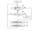
球体情報生成部82による球体情報生成処理は、第1ないし第3の検出信号Sx,Sy,Szを用いた計算によって球体情報Ssを生成する。球体情報Ssは、近似球面を有する仮想の球体の中心座標および半径のデータを含む。仮想の球体の中心座標および半径は、例えば、4つの測定点と球面の方程式を用いて、4つの測定点を含む近似球面を決定することによって求めてもよい。あるいは、仮想の球体の中心座標および半径は、5つ以上の測定点と球面の方程式と最小二乗法とを用いて、5つ以上の測定点に最も近い近似球面を決定することによって求めてもよい。 The sphere information generation process by the sphere
本実施の形態では、球体情報生成部82は、通知信号Snを受信することができるように構成されていると共に、通知信号Snを受信したら球体情報生成処理を開始するように構成されている。言い換えると、オフセット変化検出部73によるオフセット変化検出処理は、オフセットの変化を検出したら、通知信号Snを球体情報生成部82に対して出力して、球体情報生成処理を開始させる。 In the present embodiment, the sphere
オフセット補正部81によるオフセット補正処理は、球体情報生成処理が実行された後に、第1ないし第3の検出信号Sx,Sy,Szと、球体情報生成処理によって生成された球体情報Ssのうちの中心座標のデータとを用いて、第1ないし第3の検出信号Sx,Sy,Szのオフセットを補正して、第1ないし第3の補正後信号を生成し、位置情報生成部84に対して出力する。 The offset correction process by the offset
なお、球体情報生成部82は、位置検出装置1の使用開始後における最初のオフセット変化検出処理が実行される前に、球体情報生成処理を実行してもよい。あるいは、球体情報生成部82は、初期球体情報を保持していてもよい。初期球体情報は、前記の仮想の球体の中心座標の初期値および半径の初期値のデータを含んでいる。中心座標の初期値および半径の初期値のデータは、例えば、位置検出装置1が適用される関節機構300の構成に基づいて、関節機構300を含む機器の出荷前に決定される。位置検出装置1の使用開始後における最初の球体情報生成処理が実行される前においては、オフセット補正部81は、中心座標のデータの代わりに中心座標の初期値のデータを用いてオフセット補正処理を行ってもよい。 The sphere
なお、前述の中点の座標の初期値は、中心座標の初期値と同じ値であってもよい。同様に、前述の磁界強度データMの初期値は、半径の初期値と同じ値であってもよい。 The initial value of the coordinates of the midpoint described above may be the same as the initial value of the center coordinates. Similarly, the initial value of the magnetic field strength data M described above may be the same as the initial value of the radius.
位置情報生成部84における位置情報生成処理は、第1ないし第3の補正後信号に基づいて、磁気センサ装置4に対する磁界発生器2の相対的な位置を表す位置情報を生成する。 The position information generation process in the position
次に、最大線分抽出部71による第1の処理について具体的に説明する。第1の処理では、複数のタイミングにおける複数の測定点を取得し、この複数の測定点の中から第1点と第2点を抽出する。以下、第1点と第2点を抽出する方法の例として、第1の方法、第2の方法および第3の方法について説明する。第1ないし第3の方法では、最大線分抽出部71は、複数のタイミングにおける複数の測定点を時系列データとして取得する。 Next, the first process by the maximum line
始めに、図13および図14を参照して、第1の方法について説明する。図13は、第1の方法を示すフローチャートである。図14は、第1の方法を説明するための説明図である。なお、前述のように、複数の測定点は、近似球面上または近似球面の近傍に分布する。図14では、便宜上、近似球面を、記号Sを付した円で表している。 First, the first method will be described with reference to FIGS. 13 and 14. FIG. 13 is a flowchart showing the first method. FIG. 14 is an explanatory diagram for explaining the first method. As described above, the plurality of measurement points are distributed on the approximate sphere or in the vicinity of the approximate sphere. In FIG. 14, for convenience, the approximate sphere is represented by a circle with the symbol S.
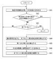
第1の方法では、まず、最初の測定点を第1点P1とし、次の測定点を第2点P2とする(ステップS11)。次に、第1点P1と第2点P2の間の距離を算出し、この距離を最大距離MDとする(ステップS12)。次に、最新の測定点Pを取得する(ステップS13)。次に、第1点P1と最新の測定点Pの間の距離を算出し、この距離を比較用距離Dとする(ステップS14)。 In the first method, first, the first measurement point is set to the first point P1, and the next measurement point is set to the second point P2 (step S11). Next, the distance between the first point P1 and the second point P2 is calculated, and this distance is set as the maximum distance MD (step S12). Next, the latest measurement point P is acquired (step S13). Next, the distance between the first point P1 and the latest measurement point P is calculated, and this distance is set as the comparison distance D (step S14).
次に、比較用距離Dが最大距離MDよりも大きいか否かを判断する(ステップS15)。図14は、比較用距離Dが最大距離MDよりも大きい場合を示している。図14に示したように、比較用距離Dが最大距離MDよりも大きい場合(YES)には、最新の測定点Pを第2点P2とし(ステップS16)、ステップS12に戻る。 Next, it is determined whether or not the comparison distance D is larger than the maximum distance MD (step S15). FIG. 14 shows a case where the comparison distance D is larger than the maximum distance MD. As shown in FIG. 14, when the comparison distance D is larger than the maximum distance MD (YES), the latest measurement point P is set as the second point P2 (step S16), and the process returns to step S12.
比較用距離Dが最大距離MD以下の場合(ステップS15におけるNO)には、次に、最大距離MDの最後の更新から所定時間以上経過しているか否かを判断する(ステップS17)。最大距離MDの最後の更新から所定時間以上経過している場合(ステップS17におけるYES)には、第1点P1と第2点P2を確定する(ステップS18)。最大距離MDの最後の更新から所定時間以上経過していない場合(ステップS17におけるNO)には、ステップS13に戻る。 When the comparison distance D is equal to or less than the maximum distance MD (NO in step S15), it is next determined whether or not a predetermined time or more has passed since the last update of the maximum distance MD (step S17). When a predetermined time or more has passed since the last update of the maximum distance MD (YES in step S17), the first point P1 and the second point P2 are determined (step S18). If a predetermined time or more has not passed since the last update of the maximum distance MD (NO in step S17), the process returns to step S13.
ステップS17においてYESの場合には、最大距離MDが所定値以上であるか否かを判断するようにしてもよい。そして、最大距離MDが所定値以上である場合にはステップS18に進み、最大距離MDが所定値未満の場合には、第1点P1と第2点P2を確定せずに、エラーである旨の通知を出力して、処理を終了してもよい。 If YES in step S17, it may be determined whether or not the maximum distance MD is equal to or greater than a predetermined value. Then, when the maximum distance MD is equal to or more than the predetermined value, the process proceeds to step S18, and when the maximum distance MD is less than the predetermined value, the first point P1 and the second point P2 are not determined and an error occurs. Notification may be output to end the process.
また、図13に示した方法では、最大線分抽出部71は、測定点Pを取得するたびに、測定点Pを第2点P2とするか否かを判断しているが、最大線分抽出部71は、最初に所定の数の測定点Pを取得してから、取得した全ての測定点Pについて、順次、第2点P2とするか否かを判断してもよい。 Further, in the method shown in FIG. 13, the maximum line
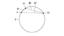
次に、図15ないし図18を参照して、第2の方法について説明する。図15は、第2の方法を示すフローチャートである。図16ないし図18は、第2の方法を説明するための説明図である。なお、図16ないし図18では、図14と同様に、便宜上、近似球面を、記号Sを付した円で表している。 Next, the second method will be described with reference to FIGS. 15 to 18. FIG. 15 is a flowchart showing the second method. 16 to 18 are explanatory views for explaining the second method. In FIGS. 16 to 18, similarly to FIG. 14, the approximate sphere is represented by a circle with the symbol S for convenience.
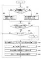
第2の方法では、まず、最初の測定点を第1点P1とし、次の測定点を第2点P2とする(ステップS21)。次に、第1点P1と第2点P2の間の距離を算出し、この距離を最大距離MDとする(ステップS22)。次に、最新の測定点Pを取得する(ステップS23)。次に、第1点P1と最新の測定点Pの間の距離を算出し、この距離を第1の比較用距離D1とすると共に、第2点P2と最新の測定点Pの間の距離を算出し、この距離を第2の比較用距離D2とする(ステップS24)。 In the second method, first, the first measurement point is set to the first point P1, and the next measurement point is set to the second point P2 (step S21). Next, the distance between the first point P1 and the second point P2 is calculated, and this distance is set as the maximum distance MD (step S22). Next, the latest measurement point P is acquired (step S23). Next, the distance between the first point P1 and the latest measurement point P is calculated, and this distance is set as the first comparison distance D1, and the distance between the second point P2 and the latest measurement point P is set. Calculated, and this distance is set as the second comparison distance D2 (step S24).
次に、第1の比較用距離D1と第2の比較用距離D2の少なくとも一方が最大距離MDよりも大きいか否かを判断する(ステップS25)。図16は、第1および第2の比較用距離D1,D2が、いずれも最大距離MDよりも小さい場合を示している。図17は、第1の比較用距離D1が最大距離MDおよび第2の比較用距離D2よりも大きい場合を示している。図18は、第2の比較用距離D2が最大距離MDおよび第1の比較用距離D1よりも大きい場合を示している。 Next, it is determined whether or not at least one of the first comparison distance D1 and the second comparison distance D2 is larger than the maximum distance MD (step S25). FIG. 16 shows a case where the first and second comparison distances D1 and D2 are both smaller than the maximum distance MD. FIG. 17 shows a case where the first comparison distance D1 is larger than the maximum distance MD and the second comparison distance D2. FIG. 18 shows a case where the second comparison distance D2 is larger than the maximum distance MD and the first comparison distance D1.
図17および図18に示したように、第1の比較用距離D1と第2の比較用距離D2の少なくとも一方が最大距離MDよりも大きい場合(ステップS25におけるYES)には、次に、第2の比較用距離D2が第1の比較用距離D1よりも大きいか否かを判断する(ステップS26)。図18に示したように、第2の比較用距離D2が第1の比較用距離D1よりも大きい場合(ステップS26におけるYES)には、最新の測定点Pを第1点P1とし(ステップS27)、ステップS22に戻る。図17に示したように、第2の比較用距離D2が第1の比較用距離D1以下の場合(ステップS26におけるNO)には、最新の測定点Pを第2点P2とし(ステップS28)、ステップS22に戻る。 As shown in FIGS. 17 and 18, when at least one of the first comparison distance D1 and the second comparison distance D2 is larger than the maximum distance MD (YES in step S25), then, the second It is determined whether or not the comparison distance D2 of 2 is larger than the first comparison distance D1 (step S26). As shown in FIG. 18, when the second comparison distance D2 is larger than the first comparison distance D1 (YES in step S26), the latest measurement point P is set as the first point P1 (step S27). ), Return to step S22. As shown in FIG. 17, when the second comparison distance D2 is equal to or less than the first comparison distance D1 (NO in step S26), the latest measurement point P is set as the second point P2 (step S28). , Return to step S22.
図16に示したように、第1および第2の比較用距離D1,D2が、いずれも最大距離MD以下の場合(ステップS25におけるNO)には、次に、最大距離MDの最後の更新から所定時間以上経過しているか否かを判断する(ステップS29)。最大距離MDの最後の更新から所定時間以上経過している場合(ステップS29におけるYES)には、第1点P1と第2点P2を確定する(ステップS30)。最大距離MDの最後の更新から所定時間以上経過していない場合(ステップS29におけるNO)には、ステップS23に戻る。 As shown in FIG. 16, when the first and second comparison distances D1 and D2 are both equal to or less than the maximum distance MD (NO in step S25), then from the last update of the maximum distance MD. It is determined whether or not the predetermined time has passed (step S29). When a predetermined time or more has passed since the last update of the maximum distance MD (YES in step S29), the first point P1 and the second point P2 are determined (step S30). If a predetermined time or more has not passed since the last update of the maximum distance MD (NO in step S29), the process returns to step S23.
ステップS29においてYESの場合には、最大距離MDが所定値以上であるか否かを判断するようにしてもよい。そして、最大距離MDが所定値以上である場合にはステップS30に進み、最大距離MDが所定値未満の場合には、第1点P1と第2点P2を確定せずに、エラーである旨の通知を出力して、処理を終了してもよい。 If YES in step S29, it may be determined whether or not the maximum distance MD is equal to or greater than a predetermined value. Then, when the maximum distance MD is equal to or more than the predetermined value, the process proceeds to step S30, and when the maximum distance MD is less than the predetermined value, the first point P1 and the second point P2 are not determined and an error occurs. Notification may be output to end the process.
また、図15に示した方法では、最大線分抽出部71は、測定点Pを取得するたびに、測定点Pを第1点P1または第2点P2とするか否かを判断しているが、最大線分抽出部71は、最初に所定の数の測定点Pを取得してから、取得した全ての測定点Pについて、順次、第1点P1または第2点P2とするか否かを判断してもよい。 Further, in the method shown in FIG. 15, the maximum line
次に、第3の方法について説明する。第3の方法では、予め、仮想の球体の直径の候補を3つ以上決めておき、3つ以上の仮想の球体の直径の候補のいずれかに最も近く且つ最も長い線分を形成する2つの測定点を、第1点および第2点とする。以下、第1点および第2点が確定する前の最新の時点で、各直径の候補に最も近く且つ最も長い線分を形成する2つの測定点の各々を候補点と言い、2つの候補点を合わせて候補点対と言う。 Next, the third method will be described. In the third method, three or more virtual sphere diameter candidates are determined in advance, and two lines forming the closest and longest line segment to any of the three or more virtual sphere diameter candidates are formed. The measurement points are the first point and the second point. Hereinafter, each of the two measurement points forming the longest line segment closest to the candidate of each diameter at the latest time point before the first point and the second point are determined is referred to as a candidate point, and the two candidate points are referred to as candidate points. Are collectively called a candidate point pair.
以下、仮想の球体の直径の候補を第1軸ないし第9軸とした例について説明する。第1軸ないし第9軸は、複数の測定点がプロットされる基準座標系を用いて以下のように定義される。以下の説明において、αは任意の実数である。第1軸は、直線上の点の座標が(α,0,0)と表される直線に平行な軸である。第2軸は、直線上の点の座標が(0,α,0)と表される直線に平行な軸である。第3軸は、直線上の点の座標が(0,0,α)と表される直線に平行な軸である。第4軸は、直線上の点の座標が(α,α,0)と表される直線に平行な軸である。第5軸は、直線上の点の座標が(α,−α,0)と表される直線に平行な軸である。第6軸は、直線上の点の座標が(0,α,α)と表される直線に平行な軸である。第7軸は、直線上の点の座標が(0,α,−α)と表される直線に平行な軸である。第8軸は、直線上の点の座標が(α,0,α)と表される直線に平行な軸である。第9軸は、直線上の点の座標が(−α,0,α)と表される直線に平行な軸である。 Hereinafter, an example in which the candidates for the diameter of the virtual sphere are set to the first axis to the ninth axis will be described. The first to ninth axes are defined as follows using a reference coordinate system in which a plurality of measurement points are plotted. In the following description, α is an arbitrary real number. The first axis is an axis parallel to the straight line in which the coordinates of the points on the straight line are represented as (α, 0, 0). The second axis is an axis parallel to the straight line in which the coordinates of the points on the straight line are represented as (0, α, 0). The third axis is an axis parallel to the straight line in which the coordinates of the points on the straight line are represented as (0, 0, α). The fourth axis is an axis parallel to the straight line in which the coordinates of the points on the straight line are represented as (α, α, 0). The fifth axis is an axis parallel to the straight line in which the coordinates of the points on the straight line are represented as (α, −α, 0). The sixth axis is an axis parallel to the straight line in which the coordinates of the points on the straight line are represented as (0, α, α). The seventh axis is an axis parallel to the straight line in which the coordinates of the points on the straight line are represented as (0, α, −α). The eighth axis is an axis parallel to the straight line in which the coordinates of the points on the straight line are represented as (α, 0, α). The ninth axis is an axis parallel to the straight line in which the coordinates of the points on the straight line are represented by (−α, 0, α).
以下、第1点および第2点が確定する前の最新の時点で、第1軸に最も近く且つ最も長い線分を形成する2つの候補点を候補点P11,P12と言い、候補点P11,P12を合わせて第1の候補点対と言う。候補点P11は、複数の測定点のうち、第1の検出信号Sxの値が最大となる測定点である。候補点P12は、複数の測定点のうち、第1の検出信号Sxの値が最小となる測定点である。 Hereinafter, the two candidate points forming the longest line segment closest to the first axis at the latest time point before the first point and the second point are determined are referred to as candidate points P11 and P12, and the candidate points P11, Together with P12, it is called the first candidate point pair. The candidate point P11 is a measurement point having the maximum value of the first detection signal Sx among the plurality of measurement points. The candidate point P12 is a measurement point having the smallest value of the first detection signal Sx among the plurality of measurement points.
また、第1点および第2点が確定する前の最新の時点で、第2軸に最も近く且つ最も長い線分を形成する2つの候補点を候補点P21,P22と言い、候補点P21,P22を合わせて第2の候補点対と言う。候補点P21は、複数の測定点のうち、第2の検出信号Syの値が最大となる測定点である。候補点P22は、複数の測定点のうち、第2の検出信号Syの値が最小となる測定点である。 Further, the two candidate points forming the longest line segment closest to the second axis at the latest time point before the first point and the second point are determined are called candidate points P21 and P22, and the candidate points P21, Together with P22, it is called the second candidate point pair. The candidate point P21 is a measurement point having the maximum value of the second detection signal Sy among the plurality of measurement points. The candidate point P22 is a measurement point having the smallest value of the second detection signal Sy among the plurality of measurement points.
また、第1点および第2点が確定する前の最新の時点で、第3軸に最も近く且つ最も長い線分を形成する2つの候補点を候補点P31,P32と言い、候補点P31,P32を合わせて第3の候補点対と言う。候補点P31は、複数の測定点のうち、第3の検出信号Szの値が最大となる測定点である。候補点P32は、複数の測定点のうち、第3の検出信号Szの値が最小となる測定点である。 Further, the two candidate points forming the longest line segment closest to the third axis at the latest time point before the first point and the second point are determined are called candidate points P31 and P32, and the candidate points P31, Together with P32, it is called the third candidate point pair. The candidate point P31 is a measurement point having the maximum value of the third detection signal Sz among the plurality of measurement points. The candidate point P32 is a measurement point having the smallest value of the third detection signal Sz among the plurality of measurement points.
また、第1点および第2点が確定する前の最新の時点で、第4軸に最も近く且つ最も長い線分を形成する2つの候補点を候補点P41,P42と言い、候補点P41,P42を合わせて第4の候補点対と言う。候補点P41は、複数の測定点のうち、Sx+Syの値が最大となる測定点である。候補点P42は、複数の測定点のうち、Sx+Syの値が最小となる測定点である。 Further, the two candidate points forming the longest line segment closest to the fourth axis at the latest time before the first point and the second point are determined are called candidate points P41 and P42, and the candidate points P41, Together with P42, it is called the fourth candidate point pair. The candidate point P41 is a measurement point having the maximum value of Sx + Sy among the plurality of measurement points. The candidate point P42 is a measurement point having the smallest value of Sx + Sy among the plurality of measurement points.
また、第1点および第2点が確定する前の最新の時点で、第5軸に最も近く且つ最も長い線分を形成する2つの候補点を候補点P51,P52と言い、候補点P51,P52を合わせて第5の候補点対と言う。候補点P51は、複数の測定点のうち、Sx−Syの値が最大となる測定点である。候補点P52は、複数の測定点のうち、Sx−Syの値が最小となる測定点である。 Further, the two candidate points forming the longest line segment closest to the fifth axis at the latest time point before the first point and the second point are determined are called candidate points P51 and P52, and the candidate points P51, Together with P52, it is called the fifth candidate point pair. The candidate point P51 is a measurement point having the maximum value of Sx-Sy among the plurality of measurement points. The candidate point P52 is a measurement point having the smallest value of Sx-Sy among the plurality of measurement points.
また、第1点および第2点が確定する前の最新の時点で、第6軸に最も近く且つ最も長い線分を形成する2つの候補点を候補点P61,P62と言い、候補点P61,P62を合わせて第6の候補点対と言う。候補点P61は、複数の測定点のうち、Sy+Szの値が最大となる測定点である。候補点P62は、複数の測定点のうち、Sy+Szの値が最小となる測定点である。 Further, the two candidate points forming the longest line segment closest to the sixth axis at the latest time point before the first point and the second point are determined are called candidate points P61 and P62, and the candidate points P61, Together with P62, it is called the sixth candidate point pair. The candidate point P61 is a measurement point having the maximum value of Sy + Sz among the plurality of measurement points. The candidate point P62 is a measurement point having the smallest value of Sy + Sz among the plurality of measurement points.
また、第1点および第2点が確定する前の最新の時点で、第7軸に最も近く且つ最も長い線分を形成する2つの候補点を候補点P71,P72と言い、候補点P71,P72を合わせて第7の候補点対と言う。候補点P71は、複数の測定点のうち、Sy−Szの値が最大となる測定点である。候補点P72は、複数の測定点のうち、Sy−Szの値が最小となる測定点である。 Further, the two candidate points forming the longest line segment closest to the seventh axis at the latest time before the first point and the second point are determined are called candidate points P71 and P72, and the candidate points P71, Together with P72, it is called the 7th candidate point pair. The candidate point P71 is a measurement point having the maximum value of Sy—Sz among the plurality of measurement points. The candidate point P72 is a measurement point having the smallest value of Sy—Sz among the plurality of measurement points.
また、第1点および第2点が確定する前の最新の時点で、第8軸に最も近く且つ最も長い線分を形成する2つの候補点を候補点P81,P82と言い、候補点P81,P82を合わせて第8の候補点対と言う。候補点P81は、複数の測定点のうち、Sz+Sxの値が最大となる測定点である。候補点P82は、複数の測定点のうち、Sz+Sxの値が最小となる測定点である。 Further, the two candidate points forming the longest line segment closest to the eighth axis at the latest time before the first point and the second point are determined are called candidate points P81 and P82, and the candidate points P81, Together with P82, it is called the 8th candidate point pair. The candidate point P81 is a measurement point having the maximum value of Sz + Sx among the plurality of measurement points. The candidate point P82 is a measurement point having the smallest value of Sz + Sx among the plurality of measurement points.
また、第1点および第2点が確定する前の最新の時点で、第9軸に最も近く且つ最も長い線分を形成する2つの候補点を候補点P91,P92と言い、候補点P91,P92を合わせて第9の候補点対と言う。候補点P91は、複数の測定点のうち、Sz−Sxの値が最大となる測定点である。候補点P92は、複数の測定点のうち、Sz−Sxの値が最小となる測定点である。 Further, the two candidate points forming the longest line segment closest to the ninth axis at the latest time point before the first point and the second point are determined are called candidate points P91 and P92, and the candidate points P91, Together with P92, it is called the 9th candidate point pair. The candidate point P91 is a measurement point having the maximum value of Sz-Sx among the plurality of measurement points. The candidate point P92 is a measurement point having the smallest value of Sz-Sx among the plurality of measurement points.
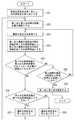
次に、図19を参照して、上述のように仮想の球体の直径の候補を第1軸ないし第9軸とした場合を例にとって、第3の方法について具体的に説明する。図19は、第3の方法を示すフローチャートである。 Next, with reference to FIG. 19, the third method will be specifically described by taking as an example the case where the candidate for the diameter of the virtual sphere is the first axis to the ninth axis as described above. FIG. 19 is a flowchart showing the third method.
第3の方法では、まず、最初の測定点を18個の候補点P11,P12,P21,P22,P31,P32,P41,P42,P51,P52,P61,P62,P71,P72,P81,P82,P91,P92とする(ステップS31)。次に、第1ないし第9の候補点対毎に、2つの候補点間の距離である2点間距離を求める(ステップS32)。ステップS32の実行時点では、第1ないし第9の候補点対の2点間距離は全て0である。18個の候補点と第1ないし第9の候補点対毎の2点間距離は、更新されるまで、最大線分抽出部71によって保持される。 In the third method, first, the first measurement point is set to 18 candidate points P11, P12, P21, P22, P31, P32, P41, P42, P51, P52, P61, P62, P71, P72, P81, P82, It is set to P91 and P92 (step S31). Next, for each of the first to ninth candidate point pairs, the distance between two points, which is the distance between the two candidate points, is obtained (step S32). At the time of execution of step S32, the distances between the two points of the first to ninth candidate point pairs are all 0. The distance between the 18 candidate points and the two points for each of the first to ninth candidate point pairs is held by the maximum line
次に、最新の測定点を取得する(ステップS33)。次に、最新の測定点と18個の候補点とを比較して、最新の測定点が1つ以上の候補点に該当するか否かを判断する(ステップS34)。この判断は、最新の測定点を、保持されている18個の候補点と比較することによって行われる。最新の測定点が1つ以上の候補点に該当する場合(YES)には、該当する候補点を最新の測定点によって更新する(ステップS35)。次に、更新された候補点を含む候補点対の2点間距離を更新し(ステップS36)、ステップS33に戻る。 Next, the latest measurement point is acquired (step S33). Next, the latest measurement points are compared with 18 candidate points, and it is determined whether or not the latest measurement points correspond to one or more candidate points (step S34). This determination is made by comparing the latest measurement points with the 18 retained candidate points. When the latest measurement point corresponds to one or more candidate points (YES), the corresponding candidate point is updated with the latest measurement point (step S35). Next, the distance between the two points of the candidate point pair including the updated candidate point is updated (step S36), and the process returns to step S33.
最新の測定点が1つ以上の候補点に該当しない場合(ステップS34におけるNO)には、次に、候補点の最後の更新から所定時間以上経過しているか否かを判断する(ステップS37)。候補点の最後の更新から所定時間以上経過している場合(ステップS37におけるYES)には、最大の2点間距離を有する候補点対の2つの候補点を第1点P1と第2点P2とする(ステップS38)。候補点の最後の更新から所定時間以上経過していない場合(ステップS37におけるNO)には、ステップS33に戻る。 If the latest measurement point does not correspond to one or more candidate points (NO in step S34), then it is determined whether or not a predetermined time or more has passed since the last update of the candidate points (step S37). .. When a predetermined time or more has passed since the last update of the candidate points (YES in step S37), the two candidate points of the candidate point pair having the maximum distance between the two points are the first point P1 and the second point P2. (Step S38). If a predetermined time or more has not passed since the last update of the candidate points (NO in step S37), the process returns to step S33.
ステップS37においてYESの場合には、最大の2点間距離が所定値以上であるか否かを判断するようにしてもよい。そして、最大の2点間距離が所定値以上である場合にはステップS38に進み、最大の2点間距離が所定値未満の場合には、第1点P1と第2点P2を確定せずに、エラーである旨の通知を出力して、処理を終了してもよい。 If YES in step S37, it may be determined whether or not the maximum distance between two points is equal to or greater than a predetermined value. Then, when the maximum distance between two points is equal to or greater than a predetermined value, the process proceeds to step S38, and when the maximum distance between two points is less than a predetermined value, the first point P1 and the second point P2 are not determined. May output a notification to the effect that an error has occurred and end the process.
また、図19に示した方法では、最大線分抽出部71は、測定点を取得するたびに、測定点が1つ以上の候補点に該当するか否かを判断しているが、最大線分抽出部71は、最初に所定の数の測定点を取得してから、所定の数の測定点の中から18個の候補点を抽出し、更に、最大の2点間距離を有する候補点対の2つの候補点を第1点P1と第2点P2としてもよい。 Further, in the method shown in FIG. 19, the maximum line
次に、オフセット変化検出部73によるオフセット変化検出処理について具体的に説明する。オフセット変化検出処理では、例えば、以下のようにしてオフセットが変化したと判断する。まず、あるタイミングにおける第1ないし第3の検出信号Sx,Sy,Szの値の組を取得することによって、前述の測定点(Sx,Sy,Sz)を得る。また、中点座標演算部72によって保持されている中点の座標(mx,my,mz)および磁界強度データMを取得する。次に、判定値Dを求める。本実施の形態における判定値Dは、測定点(Sx,Sy,Sz)と中点の座標(mx,my,mz)との間の距離と磁界強度データMとの差である。判定値Dは、下記の式(5)で表される。 Next, the offset change detection process by the offset
D=√((Sx−mx)2+(Sy−my)2+(Sz−mz)2)−M …(5)D = √ ((Sx-mx)2 + (Sy-my)2 + (Sz-mx) 2 ) -M ... (5)
次に、判定値Dの絶対値と、所定の閾値とを比較する。所定の閾値は、オフセットの変化を検出するための閾値である。オフセット変化検出処理では、判定値Dの絶対値が所定の閾値以上の場合に、オフセットが変化したと判断して、通知信号Snを出力する。 Next, the absolute value of the determination value D is compared with a predetermined threshold value. A predetermined threshold value is a threshold value for detecting a change in offset. In the offset change detection process, when the absolute value of the determination value D is equal to or greater than a predetermined threshold value, it is determined that the offset has changed, and the notification signal Sn is output.
オフセット変化検出部73が第1ないし第3の検出信号Sx,Sy,Szの値の組を取得するタイミングは、第1のプロセッサ7のサンプリング周期と同期する。オフセット変化検出部73は、オフセット変化検出部73が第1ないし第3の検出信号Sx,Sy,Szの値の組を取得するたびに、オフセット変化検出処理を行ってもよい。この場合、第1のプロセッサ7のサンプリング周期を短くすると、オフセット変化検出処理の実行間隔も短くなる。 The timing at which the offset
次に、オフセット補正部81によるオフセット補正処理と位置情報生成部84による位置情報生成処理について具体的に説明する。以下の説明では、第1の補正後信号を記号CSxで表し、第2の補正後信号を記号CSyで表し、第3の補正後信号を記号CSzで表し、仮想の球体の中心座標を(cx,cy,cz)と表す。 Next, the offset correction process by the offset
前述のように、基準座標系における磁界発生器2の位置は、所定の球面に沿って変化し、複数の測定点は、近似球面上または近似球面の近傍に分布する。また、所定の球面の中心は、第1の球面の中心すなわち基準位置と一致しているか、ほぼ一致している。従って、オフセットが生じていなければ、近似球面を有する仮想の球体の中心座標(cx,cy,cz)は、基準位置と一致するか、ほぼ一致する。しかし、オフセットが生じると、仮想の球体の中心座標(cx,cy,cz)は、基準位置からずれてしまう。 As described above, the position of the
基準座標系の原点は、基準位置であってもよい。この場合、オフセット補正処理は、例えば、球体情報生成処理において算出した仮想の球体の中心座標(cx,cy,cz)が基準座標系の原点(0,0,0)になるように、測定点(Sx,Sy,Sz)を点(Sx−cx,Sy−cy,Sz−cz)に変換する処理であってもよい。この場合、第1ないし第3の補正後信号CSx,CSy,CSzは、それぞれ下記の式(6)〜(8)で表される。 The origin of the reference coordinate system may be the reference position. In this case, in the offset correction process, for example, the measurement point is set so that the center coordinates (cx, cy, cz) of the virtual sphere calculated in the sphere information generation process become the origin (0, 0, 0) of the reference coordinate system. It may be a process of converting (Sx, Sy, Sz) into a point (Sx-cx, Sy-cy, Sz-cz). In this case, the first to third corrected signals CSx, CSy, and CSz are represented by the following equations (6) to (8), respectively.
CSx=Sx−cx …(6)
CSy=Sy−cy …(7)
CSz=Sz−cz …(8)CSx = Sx-cx ... (6)
CSy = Sy-cy ... (7)
CSz = Sz-cz ... (8)
基準座標系における点(CSx,CSy,CSz)は、基準座標系における磁界発生器2の座標と対応関係を有している。位置情報生成処理は、例えば、点(CSx,CSy,CSz)の各成分すなわち第1ないし第3の補正後信号CSx,CSy,CSzを補正して、基準座標系における磁界発生器2の座標を求める処理であってもよい。第1ないし第3の補正後信号CSx,CSy,CSzの補正は、例えば、基準座標系における原点から点(CSx,CSy,CSz)までの距離が、磁気センサ装置4から磁界発生器2までの実際の距離と等しくなるように、第1ないし第3の補正後信号CSx,CSy,CSzの各々に所定の補正係数を乗算することによって行われる。 The points (CSx, CSy, CSz) in the reference coordinate system have a correspondence relationship with the coordinates of the
次に、図20を参照して、第1の処理、第2の処理およびオフセット変化検出処理に関する第1のプロセッサ7の動作について説明する。図20は、第1のプロセッサ7の動作を示すフローチャートである。図20に示した動作では、まず、オフセット変化検出部73が、前述のように、中点座標演算部72によって保持されている推定球体情報を用いて、判定値Dを求める(ステップS41)。 Next, with reference to FIG. 20, the operation of the
オフセット変化検出部73は、次に、判定値Dの絶対値が所定の閾値以上か否かを判断する(ステップS42)。ステップS42において判定値Dが所定の閾値以上ではない場合(NO)には、第1のプロセッサ7は、図20に示した動作を終了するか否かを判断する(ステップS43)。ステップS43において終了すると判断された場合(YES)には、図20に示した動作を終了する。図20に示した動作は、例えば、終了を指示する信号が第1のプロセッサ7に入力されることによって終了する。ステップS43において終了しないと判断された場合(NO)には、ステップS41に戻る。ステップS42において判定値Dが所定の閾値以上の場合(YES)には、オフセット変化検出部73は、通知信号Snを出力すると共に、オフセット変化検出処理を停止する(ステップS44)。 Next, the offset
図20に示した動作では、次に、最大線分抽出部71が、第1の処理を実行して、第1点と第2点を抽出する(ステップS45)。次に、中点座標演算部72が、第2の処理を実行して、第1点と第2点を結ぶ線分の中点の座標と磁界強度データMを求めると共に、これらを推定球体情報として保持する(ステップS46)。次に、オフセット変化検出部73が、オフセット変化検出処理を再開し(ステップS47)、ステップS41に戻る。 In the operation shown in FIG. 20, next, the maximum line
次に、図21を参照して、球体情報Ssの生成に関連する第2のプロセッサ8の動作について説明する。図21は、球体情報Ssの生成に関連する第2のプロセッサ8の動作を示すフローチャートである。図21に示した動作では、まず、球体情報生成部82が、通知信号Snを受信したか否かを確認する(ステップS51)。ステップS51において通知信号Snを受信していない場合(NO)には、第2のプロセッサ8は、図21に示した動作を終了するか否かを判断する(ステップS52)。ステップS52において終了すると判断された場合(YES)には、図21に示した動作を終了する。図21に示した動作は、例えば、終了を指示する信号が第2のプロセッサ8に入力されることによって終了する。ステップS52において終了しないと判断された場合(NO)には、所定の時間経過後、再度、ステップS51を実行する。
Next, with reference to FIG. 21, the operation of the
ステップS51において通知信号Snを受信した場合(YES)には、球体情報生成部82は、球体情報Ssを生成する(ステップS53)。図21に示した動作では、ステップS53を実行したら、ステップS51に戻る。 When the notification signal Sn is received in step S51 (YES), the sphere
以上説明したように、本実施の形態に係る信号処理回路5、位置検出装置1および磁気センサシステム3では、複数のタイミングにおける複数の測定点の中から、それらを結ぶ線分の長さが最大となる第1点と第2点を抽出する第1の処理と、第1の処理によって抽出された第1点と第2点を結ぶ線分の中点の座標を求める第2の処理が行われる。第1点と第2点を結ぶ線分の中点の座標は、仮想の球体の中心座標を推定した座標に相当する。 As described above, in the
ところで、仮想の球体の中心座標の算出方法としては、球体情報生成処理によって球体情報Ssを生成する方法がある。前述のように、球体情報Ssすなわち仮想の球体の中心座標および半径を求めるためには、例えば、球面の方程式を用いて近似球面を決定することが必要である。そのため、球体情報Ssを生成する処理は、比較的複雑な演算が必要であり、ある程度時間を要する。 By the way, as a method of calculating the center coordinates of a virtual sphere, there is a method of generating sphere information Ss by sphere information generation processing. As described above, in order to obtain the sphere information Ss, that is, the center coordinates and radius of the virtual sphere, it is necessary to determine the approximate sphere using, for example, the equation of the sphere. Therefore, the process of generating the sphere information Ss requires a relatively complicated calculation and takes a certain amount of time.
これに対し、第1点と第2点を抽出する第1の処理と、第1点と第2点を結ぶ線分の中点の座標を求める第2の処理は、球体情報Ssを生成する処理よりも簡単な演算を用いて実行することができる。従って、本実施の形態によれば、オフセット変化検出処理によって第1ないし第3の検出信号Sx,Sy,Szのオフセットの変化が検出された後に、比較的簡単な第1の処理と第2の処理を実行することにより、オフセット変化後の仮想の球体の中心座標を速やかに推定することができる。 On the other hand, the first process of extracting the first and second points and the second process of obtaining the coordinates of the midpoint of the line segment connecting the first and second points generate sphere information Ss. It can be executed using operations that are simpler than processing. Therefore, according to the present embodiment, after the offset change detection process detects the offset change of the first to third detection signals Sx, Sy, Sz, the first process and the second process are relatively simple. By executing the process, the center coordinates of the virtual sphere after the offset change can be quickly estimated.
また、本実施の形態では、第2の処理は、更に、磁界強度データMを求め、中点の座標と磁界強度データMを推定球体情報として保持する。オフセット変化検出処理は、第2の処理によって保持されている推定球体情報を用いて行われる。従って、本実施の形態によれば、第1ないし第3の検出信号Sx,Sy,Szのオフセットの変化が検出された後にオフセット変化検出処理を停止した場合に、比較的簡単な第1の処理と第2の処理を実行することにより、オフセット変化検出処理を速やかに再開することができる。 Further, in the second embodiment, the second process further obtains the magnetic field strength data M, and holds the coordinates of the midpoint and the magnetic field strength data M as estimated sphere information. The offset change detection process is performed using the estimated sphere information held by the second process. Therefore, according to the present embodiment, when the offset change detection process is stopped after the offset change of the first to third detection signals Sx, Sy, Sz is detected, the first process is relatively simple. By executing the second process, the offset change detection process can be restarted promptly.
[第2の実施の形態]
次に、本発明の第2の実施の形態について説明する。始めに、図22を参照して、本実施の形態に係る信号処理回路5が第1の実施の形態と異なる点について説明する。図22は、本実施の形態に係る磁気センサシステム3の構成を示す機能ブロック図である。[Second Embodiment]
Next, a second embodiment of the present invention will be described. First, with reference to FIG. 22, the difference between the
本実施の形態に係る信号処理回路5は、第1の実施の形態で説明した第1の処理、第2の処理、オフセット変化検出処理、球体情報生成処理、オフセット補正処理および位置情報生成処理に加えて、球体情報受信・保持処理と、球体情報送信処理とを行う。信号処理回路5の第1のプロセッサ7は、第1の実施の形態で説明した最大線分抽出部71、中点座標演算部72およびオフセット変化検出部73に加えて、球体情報受信・保持処理を行う球体情報受信・保持部74を含んでいる。信号処理回路5の第2のプロセッサ8は、第1の実施の形態で説明したオフセット補正部81、球体情報生成部82および位置情報生成部84に加えて、球体情報送信処理を行う球体情報送信部83を含んでいる。 The
球体情報受信・保持部74および球体情報送信部83は、それぞれ上述の処理を行う機能ブロックである。また、球体情報受信・保持処理と球体情報送信処理は、それぞれ、位置検出装置1の使用時に、繰り返し実行される。 The sphere information receiving / holding
球体情報送信部83による球体情報送信処理は、球体情報生成部82による球体情報生成処理が実行された後に、球体情報生成処理によって生成された球体情報Ssを球体情報受信・保持部74に送信する。球体情報受信・保持部74による球体情報受信・保持処理は、球体情報送信部83から送信される球体情報Ssを受信すると共に保持する。 The sphere information transmission process by the sphere
本実施の形態では、オフセット変化検出部73によるオフセット変化検出処理は、中点座標演算部72による第2の処理によって保持されている中点の座標および磁界強度データMの組すなわち推定球体情報と、球体情報受信・保持部74による球体情報受信・保持処理によって保持されている球体情報Ss、すなわち球体情報生成処理によって生成された球体情報Ssのうちの一方を用いて行われる。 In the present embodiment, the offset change detection process by the offset
第1の実施の形態で説明したように、球体情報生成部82は、通知信号Snを受信することができるように構成されていると共に、通知信号Snを受信したら球体情報生成処理を開始するように構成されている。オフセット変化検出部73によるオフセット変化検出処理は、オフセットの変化を検出したら、通知信号Snを球体情報生成部82に対して出力して、球体情報生成処理を開始させる。球体情報生成部82による球体情報生成処理は、通知信号Snを受信したら、最新の球体情報Ssの生成を開始する。球体情報受信・保持部74による球体情報受信・保持処理は、新しい球体情報Ssを受信したら、保持している球体情報Ssを更新する。 As described in the first embodiment, the sphere
なお、球体情報生成部82が、第1の実施の形態で説明した初期球体情報を保持している場合、第1のプロセッサ7と第2のプロセッサ8では、位置検出装置1の使用開始後における最初の球体情報生成処理が実行される前に、以下のような初期処理を実行してもよい。この初期処理では、球体情報送信部83は、初期球体情報を球体情報受信・保持部74に送信する。球体情報受信・保持部74は、初期球体情報を受信すると共に保持する。最初の球体情報生成処理が実行される前においては、オフセット変化検出部73は、推定球体情報を用いてオフセットの変化を検出してもよいし、第1の実施の形態で説明した初期推定球体情報を用いてオフセットの変化を検出してもよいし、初期球体情報を用いてオフセットの変化を検出してもよい。 When the sphere
以下、オフセット変化検出部73によるオフセット変化検出処理について具体的に説明する。オフセット変化検出処理では、推定球体情報を用いる第1の場合と、球体情報Ssを用いる第2の場合のいずれにおいても、第1の実施の形態におけるオフセット変化検出処理と同様に、判定値Dを求め、判定値Dの絶対値と、所定の閾値とを比較し、判定値Dの絶対値が所定の閾値以上の場合に、オフセットが変化したと判断して、通知信号Snを出力する。第1の場合における判定値Dの算出方法は、第1の実施の形態と同じである。すなわち、第1の場合における判定値Dは、前出の式(5)で表される。 Hereinafter, the offset change detection process by the offset
第2の場合における判定値Dは、以下のようにして求められる。まず、あるタイミングにおける第1ないし第3の検出信号Sx,Sy,Szの値の組を取得することによって、前述の測定点(Sx,Sy,Sz)を得る。また、球体情報受信・保持部74によって保持されている球体情報Ssを取得する。次に、測定点(Sx,Sy,Sz)と球体情報Ssによる仮想の球体の中心座標(cx,cy,cz)との間の距離と、この距離と球体情報Ssによる仮想の球体の半径rとの差を求める。この差が、第2の場合における判定値Dである。第2の場合における判定値Dは、下記の式(9)で表される。 The determination value D in the second case is obtained as follows. First, the above-mentioned measurement points (Sx, Sy, Sz) are obtained by acquiring a set of values of the first to third detection signals Sx, Sy, and Sz at a certain timing. In addition, the sphere information Ss held by the sphere information receiving / holding
D=√((Sx−cx)2+(Sy−cy)2+(Sz−cz)2)−r …(9)D = √ ((Sx-cx)2 + (Sy-cy)2 + (Sz-cz)2 ) -r ... (9)
次に、図23を参照して、第1の処理、第2の処理、オフセット変化検出処理および球体情報受信・保持処理に関する第1のプロセッサ7の動作について説明する。図23は、第1のプロセッサ7の動作を示すフローチャートである。 Next, with reference to FIG. 23, the operation of the
図23に示した動作では、まず、オフセット変化検出部73が、球体情報受信・保持部74が保持する球体情報Ssの方が、中点座標演算部72が保持する推定球体情報よりも新しいか否かを確認する(ステップS61)。球体情報Ssの方が新しい場合(YES)には、オフセット変化検出部73は、球体情報Ssを用いて、式(9)によって、判定値Dを求める(ステップS62)。球体情報Ssの方が新しくない場合(NO)には、オフセット変化検出部73は、推定球体情報を用いて、式(5)によって、判定値Dを求める(ステップS63)。 In the operation shown in FIG. 23, first, is the sphere information Ss held by the sphere information receiving / holding
なお、最初の球体情報生成処理が実行される前においては、球体情報受信・保持部74は、球体情報Ssを保持していないため、ステップS63が実行される。中点座標演算部72が初期推定球体情報を保持している場合、最初の球体情報生成処理が実行される前においては、ステップS63の代わりに、オフセット変化検出部73が初期推定球体情報を用いて判定値Dを求める処理が実行されてもよい。この場合、判定値Dは、式(5)における中点の座標および磁界強度データMをそれぞれ中点の座標の初期値および磁界強度データMの初期値に置き換えることによって求めることができる。あるいは、球体情報受信・保持部74が初期球体情報を保持している場合、最初の球体情報生成処理が実行される前においては、ステップS63の代わりに、オフセット変化検出部73が初期球体情報を用いて判定値Dを求める処理が実行されてもよい。この場合、判定値Dは、式(9)における仮想の球体の中心座標および半径rをそれぞれ仮想の球体の中心座標の初期値および半径rの初期値に置き換えることによって求めることができる。 Before the first sphere information generation process is executed, the sphere information receiving / holding
図23に示した動作では、ステップS62の実行後またはステップS63の実行後に、オフセット変化検出部73が、判定値Dの絶対値が所定の閾値以上か否かを判断する(ステップS64)。ステップS64において判定値Dが所定の閾値以上ではない場合(NO)には、第1のプロセッサ7は、図23に示した動作を終了するか否かを判断する(ステップS65)。ステップS65において終了すると判断された場合(YES)には、図23に示した動作を終了する。図23に示した動作は、例えば、終了を指示する信号が第1のプロセッサ7に入力されることによって終了する。ステップS65において終了しないと判断された場合(NO)には、ステップS61に戻る。ステップS64において判定値Dが所定の閾値以上の場合(YES)には、オフセット変化検出部73は、通知信号Snを出力すると共に、オフセット変化検出処理を停止する(ステップS66)。 In the operation shown in FIG. 23, after the execution of step S62 or the execution of step S63, the offset
図23に示した動作では、次に、最大線分抽出部71が、第1の処理を実行して、第1点と第2点を抽出する(ステップS67)。次に、中点座標演算部72が、第2の処理を実行して、第1点と第2点を結ぶ線分の中点の座標と磁界強度データMを求めると共に、これらを推定球体情報として保持する(ステップS68)。次に、オフセット変化検出部73が、オフセット変化検出処理を再開し(ステップS69)、ステップS61に戻る。 In the operation shown in FIG. 23, the maximum line
次に、図24を参照して、球体情報Ssの生成と送信に関連する第2のプロセッサ8の動作について説明する。図24は、球体情報Ssの生成と送信に関連する第2のプロセッサ8の動作を示すフローチャートである。図24に示した動作では、まず、球体情報生成部82が、通知信号Snを受信したか否かを確認する(ステップS71)。ステップS71において通知信号Snを受信していない場合(NO)には、第2のプロセッサ8は、図24に示した動作を終了するか否かを判断する(ステップS72)。ステップS72において終了すると判断された場合(YES)には、図24に示した動作を終了する。図24に示した動作は、例えば、終了を指示する信号が第2のプロセッサ8に入力されることによって終了する。ステップS72において終了しないと判断された場合(NO)には、所定の時間経過後、再度、ステップS71を実行する。 Next, with reference to FIG. 24, the operation of the
ステップS71において通知信号Snを受信した場合(YES)には、球体情報生成部82は、球体情報Ssを生成する(ステップS73)。次に、球体情報送信部83が、球体情報Ssを球体情報受信・保持部74に送信する(ステップS74)。図24に示した動作では、ステップS74を実行したら、ステップS71に戻る。 When the notification signal Sn is received in step S71 (YES), the sphere
以上説明したように、本実施の形態では、オフセット変化検出処理は、第2の処理によって保持されている中点の座標および磁界強度データMの組すなわち推定球体情報と、球体情報生成処理によって生成された球体情報Ssのうちの一方を用いて行われる。中点の座標は、仮想の球体の中心座標を推定した座標に相当し、磁界強度データMは、仮想の球体の半径を推定したデータに相当する。推定球体情報を用いる場合には、第1の実施の形態と同様に、オフセット変化検出処理を速やかに再開することができる。 As described above, in the present embodiment, the offset change detection process is generated by the set of the coordinates of the midpoint and the magnetic field strength data M held by the second process, that is, the estimated sphere information, and the sphere information generation process. It is performed using one of the obtained sphere information Ss. The coordinates of the midpoint correspond to the coordinates obtained by estimating the center coordinates of the virtual sphere, and the magnetic field strength data M corresponds to the data obtained by estimating the radius of the virtual sphere. When the estimated sphere information is used, the offset change detection process can be restarted promptly as in the first embodiment.
一方、球体情報生成処理によって生成された球体情報Ssは、中点の座標および磁界強度データMのような仮想の球体の中心座標および半径の推定値ではなく、仮想の球体の中心座標および半径そのものである。従って、本実施の形態によれば、球体情報生成処理によって生成された球体情報Ssを用いてオフセット変化検出処理を行うことにより、第1ないし第3の検出信号Sx,Sy,Szのオフセットの変化を精度よく検出することができる。 On the other hand, the sphere information Ss generated by the sphere information generation process is not an estimated value of the center coordinates and radius of the virtual sphere such as the coordinates of the midpoint and the magnetic field strength data M, but the center coordinates and radius of the virtual sphere itself. Is. Therefore, according to the present embodiment, the offset change detection process of the first to third detection signals Sx, Sy, Sz is performed by performing the offset change detection process using the sphere information Ss generated by the sphere information generation process. Can be detected accurately.
また、本実施の形態では、オフセット変化検出処理は、球体情報生成処理を開始させてから所定時間以内に新しい球体情報Ssが得られたときには、この新しい球体情報Ssを用いて行われ、球体情報生成処理を開始させてから所定時間以内に新しい球体情報Ssが得られなかったときには、推定球体情報を用いて行われる。これにより、本実施の形態によれば、オフセット変化検出処理を速やかに再開することができる。また、本実施の形態によれば、球体情報受信・保持部74が、球体情報送信部83から送信された球体情報Ssを受信できなかった場合であっても、オフセット変化検出処理を再開することができる。 Further, in the present embodiment, the offset change detection process is performed using the new sphere information Ss when new sphere information Ss is obtained within a predetermined time after starting the sphere information generation process, and the sphere information is performed. When new sphere information Ss is not obtained within a predetermined time after starting the generation process, the estimated sphere information is used. As a result, according to the present embodiment, the offset change detection process can be restarted promptly. Further, according to the present embodiment, even if the sphere information receiving / holding
本実施の形態におけるその他の構成、作用および効果は、第1の実施の形態と同様である。 Other configurations, actions and effects in this embodiment are similar to those in the first embodiment.
なお、本発明は、上記各実施の形態に限定されず、種々の変更が可能である。例えば、最大線分抽出部71、中点座標演算部72、オフセット変化検出部73および球体情報受信・保持部74は、第2のプロセッサ8に設けられていてもよい。 The present invention is not limited to each of the above embodiments, and various modifications can be made. For example, the maximum line
また、本発明の信号処理回路および磁気センサシステムは、磁気センサ装置に対する磁界発生器の相対的な位置を検出する場合に限らず、所定の磁界の中で回転可能に構成された磁気センサ装置の姿勢を検出する場合にも適用することができる。 Further, the signal processing circuit and the magnetic sensor system of the present invention are not limited to the case of detecting the relative position of the magnetic field generator with respect to the magnetic sensor device, and the magnetic sensor device configured to be rotatable in a predetermined magnetic field. It can also be applied when detecting a posture.
1…位置検出装置、2…磁界発生器、3…磁気センサシステム、4…磁気センサ装置、5…信号処理回路、7…第1のプロセッサ、8…第2のプロセッサ、10…第1の磁気センサ、20…第2の磁気センサ、30…第3の磁気センサ、71…最大線分抽出部、72…中点座標演算部、81…オフセット補正部、82…球体情報生成部、84…位置情報生成部、200…磁気センサ組立体、300…関節機構。 1 ... position detector, 2 ... magnetic field generator, 3 ... magnetic sensor system, 4 ... magnetic sensor device, 5 ... signal processing circuit, 7 ... first processor, 8 ... second processor, 10 ... first magnetism Sensor, 20 ... 2nd magnetic sensor, 30 ... 3rd magnetic sensor, 71 ... Maximum line segment extraction unit, 72 ... Midpoint coordinate calculation unit, 81 ... Offset correction unit, 82 ... Sphere information generation unit, 84 ... Position Information generator, 200 ... Magnetic sensor assembly, 300 ... Joint mechanism.
Claims (8)
Translated fromJapanese前記信号処理回路は、
前記第1ないし第3の検出信号の値を表すための3つの軸によって定義された直交座標系において、あるタイミングにおける前記第1ないし第3の検出信号の値の組を表す座標を測定点としたときに、複数のタイミングにおける複数の測定点の中から、それらを結ぶ線分の長さが最大となる第1点と第2点を抽出する第1の処理と、
前記第1の処理によって抽出された前記第1点と第2点を結ぶ線分の中点の座標を求める第2の処理とを行い、
前記第2の処理は、更に、前記第1点と第2点を結ぶ線分の長さの1/2を求め、これを磁界強度データとし、前記中点の座標と前記磁界強度データを保持し、
前記信号処理回路は、更に、前記第2の処理によって保持されている前記中点の座標および磁界強度データを用いて、前記第1ないし第3の検出信号のオフセットの変化を検出するオフセット変化検出処理を行うことを特徴とする信号処理回路。The first to third detection signals output from the magnetic sensor device that generates the first detection signal, the second detection signal, and the third detection signal that correspond to the components of the magnetic field in the reference position in three different directions. It is a signal processing circuit that processes the detection signal of
The signal processing circuit
In a Cartesian coordinate system defined by three axes for expressing the values of the first to third detection signals, the coordinates representing the set of the values of the first to third detection signals at a certain timing are set as measurement points. The first process of extracting the first and second points having the maximum length of the line segment connecting them from a plurality of measurement points at a plurality of timings.
There line and a second process of obtaining the coordinates of the midpoint of a line segment connecting the first of the first point and the second point extracted by theprocess,
In the second process, 1/2 of the length of the line segment connecting the first point and the second point is further obtained, this is used as magnetic field strength data, and the coordinates of the midpoint and the magnetic field strength data are retained. death,
The signal processing circuit further detects an offset change detection of the first to third detection signals by using the coordinates of the midpoint and the magnetic field strength data held by the second processing. A signal processing circuit characterizedby performing processing.
前記信号処理回路は、
前記第1ないし第3の検出信号の値を表すための3つの軸によって定義された直交座標系において、あるタイミングにおける前記第1ないし第3の検出信号の値の組を表す座標を測定点としたときに、複数のタイミングにおける複数の測定点の中から、それらを結ぶ線分の長さが最大となる第1点と第2点を抽出する第1の処理と、
前記第1の処理によって抽出された前記第1点と第2点を結ぶ線分の中点の座標を求める第2の処理と、
前記第1ないし第3の検出信号のオフセットの変化を検出するオフセット変化検出処理と、
前記第1ないし第3の検出信号を用いた計算によって、球体情報を生成する球体情報生成処理とを行い、
前記球体情報は、前記複数の測定点の分布を近似した球面を有する仮想の球体の中心座標および半径のデータを含み、
前記オフセット変化検出処理は、オフセットの変化を検出したら前記球体情報生成処理を開始させ、
前記第2の処理は、更に、前記第1点と第2点を結ぶ線分の長さの1/2を求め、これを磁界強度データとし、前記中点の座標と前記磁界強度データを保持し、
前記オフセット変化検出処理は、前記球体情報生成処理を開始させてから所定時間以内に新しい球体情報が得られたときには、前記球体情報生成処理によって生成されたこの新しい球体情報を用いて行われ、前記球体情報生成処理を開始させてから前記所定時間以内に新しい球体情報が得られなかったときには、前記第2の処理によって保持されている前記中点の座標および磁界強度データの組を用いて行われることを特徴とする信号処理回路。The first to third detection signals output from the magnetic sensor device that generates the first detection signal, the second detection signal, and the third detection signal that correspond to the components of the magnetic field in the reference position in three different directions. It is a signal processing circuit that processes the detection signal of
The signal processing circuit
In a Cartesian coordinate system defined by three axes for expressing the values of the first to third detection signals, the coordinates representing the set of the values of the first to third detection signals at a certain timing are set as measurement points. The first process of extracting the first and second points having the maximum length of the line segment connecting them from a plurality of measurement points at a plurality of timings.
The second process of obtaining the coordinates of the midpoint of the line segment connecting the first point and the second point extracted by the first process, and
The offset change detection process for detecting the offset change of the first to third detection signals, and the offset change detection process.
By calculation usingthe first to third detection signals, performsa sphere information generation processing that generates the spherical information,
The sphere information,see contains the center coordinates and the radius of the data of a virtual sphere having a spherical surface that approximates the distribution ofthe plurality of measuringpoints,
In the offset change detection process, when the offset change is detected, the sphere information generation process is started.
In the second process, 1/2 of the length of the line segment connecting the first point and the second point is further obtained, this is used as magnetic field strength data, and the coordinates of the midpoint and the magnetic field strength data are retained. death,
When new sphere information is obtained within a predetermined time after starting the sphere information generation process, the offset change detection process is performed using the new sphere information generated by the sphere information generation process. When new sphere information is not obtained within the predetermined time after starting the sphere information generation process, it is performed using the set of the coordinates of the midpoint and the magnetic field strength data held by the second process. A signal processing circuitcharacterized by the fact that.
前記オフセット補正処理は、前記球体情報生成処理によって生成された前記球体情報のうちの前記中心座標のデータを用いて、前記第1ないし第3の検出信号のオフセットを補正して、第1ないし第3の補正後信号を生成することを特徴とする請求項2記載の信号処理回路。Furthermore, offset correction processing is performed.
In the offset correction process, the offset of the first to third detection signals is corrected by using the data of the center coordinates of the sphere information generated by the sphere information generation process, and the first to third detection signals are corrected. The signal processing circuit accordingto claim 2 , wherein the corrected signal of 3 is generated.
前記信号処理回路は、 The signal processing circuit
前記第1ないし第3の検出信号の値を表すための3つの軸によって定義された直交座標系において、あるタイミングにおける前記第1ないし第3の検出信号の値の組を表す座標を測定点としたときに、複数のタイミングにおける複数の測定点の中から、それらを結ぶ線分の長さが最大となる第1点と第2点を抽出する第1の処理と、 In a Cartesian coordinate system defined by three axes for expressing the values of the first to third detection signals, the coordinates representing the set of the values of the first to third detection signals at a certain timing are set as measurement points. The first process of extracting the first and second points having the maximum length of the line segment connecting them from a plurality of measurement points at a plurality of timings.
前記第1の処理によって抽出された前記第1点と第2点を結ぶ線分の中点の座標を求める第2の処理とを行い、 The second process of obtaining the coordinates of the midpoint of the line segment connecting the first point and the second point extracted by the first process is performed.
前記第1の処理は、 The first process is
最初の前記測定点を仮の第1点とし、次の前記測定点を仮の第2点とする第1のステップと、 A first step in which the first measurement point is a tentative first point and the next measurement point is a tentative second point.
前記第1のステップの実行後、前記仮の第1点と前記仮の第2点の間の距離を算出し、この距離を最大距離とする第2のステップと、 After the execution of the first step, a second step in which the distance between the provisional first point and the provisional second point is calculated and this distance is set as the maximum distance,
前記第2のステップの実行後、最新の前記測定点を判定用測定点として取得する第3のステップと、 After the execution of the second step, the third step of acquiring the latest measurement point as a judgment measurement point, and
前記第3のステップの実行後、前記仮の第1点と前記判定用測定点の間の距離を算出し、この距離を比較用距離とする第4のステップと、 After the execution of the third step, the distance between the provisional first point and the determination measurement point is calculated, and this distance is used as the comparison distance in the fourth step.
前記第4のステップの実行後、前記比較用距離が前記最大距離よりも大きいか否かを判断する第5のステップとを実行し、 After executing the fourth step, the fifth step of determining whether or not the comparison distance is larger than the maximum distance is executed.
前記第5のステップにおいて、前記比較用距離が前記最大距離よりも大きい場合には、前記判定用測定点を前記仮の第2点とした後に、再度、前記第2のステップを実行し、 In the fifth step, when the comparison distance is larger than the maximum distance, the determination measurement point is set to the provisional second point, and then the second step is executed again.
前記第5のステップにおいて、前記比較用距離が前記最大距離以下の場合には、前記第1の処理は、更に、前記最大距離の最後の更新から所定時間以上経過しているか否かを判断する第6のステップを実行し、 In the fifth step, when the comparison distance is equal to or less than the maximum distance, the first process further determines whether or not a predetermined time or more has elapsed from the last update of the maximum distance. Perform the sixth step,
前記第6のステップにおいて、前記最大距離の最後の更新から前記所定時間以上経過している場合には、前記仮の第1点と前記仮の第2点を前記第1点と第2点として確定し、 In the sixth step, when the predetermined time or more has passed since the last update of the maximum distance, the provisional first point and the provisional second point are designated as the first point and the second point. Confirmed,
前記第6のステップにおいて、前記最大距離の最後の更新から前記所定時間以上経過していない場合には、再度、前記第3のステップを実行することを特徴とする信号処理回路。 A signal processing circuit comprising executing the third step again when the predetermined time or more has not elapsed since the last update of the maximum distance in the sixth step.
前記信号処理回路は、 The signal processing circuit
前記第1ないし第3の検出信号の値を表すための3つの軸によって定義された直交座標系において、あるタイミングにおける前記第1ないし第3の検出信号の値の組を表す座標を測定点としたときに、複数のタイミングにおける複数の測定点の中から、それらを結ぶ線分の長さが最大となる第1点と第2点を抽出する第1の処理と、 In a Cartesian coordinate system defined by three axes for expressing the values of the first to third detection signals, the coordinates representing the set of the values of the first to third detection signals at a certain timing are set as measurement points. The first process of extracting the first and second points having the maximum length of the line segment connecting them from a plurality of measurement points at a plurality of timings.
前記第1の処理によって抽出された前記第1点と第2点を結ぶ線分の中点の座標を求める第2の処理とを行い、 The second process of obtaining the coordinates of the midpoint of the line segment connecting the first point and the second point extracted by the first process is performed.
前記第1の処理は、 The first process is
最初の前記測定点を仮の第1点とし、次の前記測定点を仮の第2点とする第1のステップと、 A first step in which the first measurement point is a tentative first point and the next measurement point is a tentative second point.
前記第1のステップの実行後、前記仮の第1点と前記仮の第2点の間の距離を算出し、この距離を最大距離とする第2のステップと、 After the execution of the first step, a second step in which the distance between the provisional first point and the provisional second point is calculated and this distance is set as the maximum distance,
前記第2のステップの実行後、最新の前記測定点を判定用測定点として取得する第3のステップと、 After the execution of the second step, the third step of acquiring the latest measurement point as a judgment measurement point, and
前記第3のステップの実行後、前記仮の第1点と前記判定用測定点の間の距離を算出し、この距離を第1の比較用距離とすると共に、前記仮の第2点と前記判定用測定点の間の距離を算出し、この距離を第2の比較用距離とする第4のステップと、 After executing the third step, the distance between the provisional first point and the determination measurement point is calculated, and this distance is used as the first comparison distance, and the provisional second point and the above are described. The fourth step of calculating the distance between the measurement points for judgment and using this distance as the second comparison distance, and
前記第4のステップの実行後、前記第1の比較用距離と前記第2の比較用距離の少なくとも一方が前記最大距離よりも大きいか否かを判断する第5のステップとを実行し、 After executing the fourth step, a fifth step of determining whether at least one of the first comparison distance and the second comparison distance is larger than the maximum distance is executed.
前記第5のステップにおいて、前記第1の比較用距離と前記第2の比較用距離の少なくとも一方が前記最大距離よりも大きい場合には、前記第1の処理は、更に、前記第2の比較用距離が前記第1の比較用距離よりも大きいか否かを判断する第6のステップを実行し、 In the fifth step, when at least one of the first comparison distance and the second comparison distance is larger than the maximum distance, the first process further performs the second comparison. Performing the sixth step of determining whether or not the working distance is larger than the first comparative distance,
前記第6のステップにおいて、前記第2の比較用距離が前記第1の比較用距離よりも大きい場合には、前記判定用測定点を前記仮の第1点とした後に、再度、前記第2のステップを実行し、 In the sixth step, when the second comparison distance is larger than the first comparison distance, the determination measurement point is set to the provisional first point, and then the second comparison point is set again. Follow the steps of
前記第6のステップにおいて、前記第2の比較用距離が前記第1の比較用距離以下の場合には、前記判定用測定点を前記仮の第2点とした後に、再度、前記第2のステップを実行し、 In the sixth step, when the second comparison distance is equal to or less than the first comparison distance, the determination measurement point is set to the provisional second point, and then the second comparison point is set again. Take steps and
前記第5のステップにおいて、前記第1および第2の比較用距離が、いずれも前記最大距離以下の場合には、前記第1の処理は、更に、前記最大距離の最後の更新から所定時間以上経過しているか否かを判断する第7のステップを実行し、 In the fifth step, when the first and second comparison distances are both equal to or less than the maximum distance, the first process further performs a predetermined time or more from the last update of the maximum distance. Perform the seventh step to determine if it has passed,
前記第7のステップにおいて、前記最大距離の最後の更新から前記所定時間以上経過している場合には、前記仮の第1点と前記仮の第2点を前記第1点と第2点として確定し、 In the seventh step, when the predetermined time or more has passed since the last update of the maximum distance, the provisional first point and the provisional second point are designated as the first point and the second point. Confirmed,
前記第7のステップにおいて、前記最大距離の最後の更新から前記所定時間以上経過していない場合には、再度、前記第3のステップを実行することを特徴とする信号処理回路。 A signal processing circuit comprising executing the third step again when the predetermined time or more has not elapsed since the last update of the maximum distance in the seventh step.
前記信号処理回路は、 The signal processing circuit
前記第1ないし第3の検出信号の値を表すための3つの軸によって定義された直交座標系において、あるタイミングにおける前記第1ないし第3の検出信号の値の組を表す座標を測定点としたときに、複数のタイミングにおける複数の測定点の中から、それらを結ぶ線分の長さが最大となる第1点と第2点を抽出する第1の処理と、 In a Cartesian coordinate system defined by three axes for expressing the values of the first to third detection signals, the coordinates representing the set of the values of the first to third detection signals at a certain timing are set as measurement points. The first process of extracting the first and second points having the maximum length of the line segment connecting them from a plurality of measurement points at a plurality of timings.
前記第1の処理によって抽出された前記第1点と第2点を結ぶ線分の中点の座標を求める第2の処理とを行い、 The second process of obtaining the coordinates of the midpoint of the line segment connecting the first point and the second point extracted by the first process is performed.
前記第1点と第2点は、前記複数の測定点の分布を近似した球面を有する仮想の球体の3つ以上の直径の候補のいずれかに最も近く且つ最も長い線分を形成する2つの測定点であり、 The first and second points form the closest and longest line segment to any of the three or more diameter candidates of a virtual sphere having a sphere that approximates the distribution of the plurality of measurement points. It is a measurement point
前記第1点と第2点が確定する前の最新の時点で、前記3つ以上の直径の候補の各々に最も近く且つ最も長い線分を形成する2つの測定点の各々を候補点とし、2つの候補点を合わせて候補点対としたときに、前記第1の処理は、 At the latest time point before the first point and the second point are determined, each of the two measurement points forming the closest and longest line segment to each of the three or more diameter candidates is set as a candidate point. When the two candidate points are combined to form a candidate point pair, the first process is
最初の前記測定点を、3つ以上の前記候補点対の全ての候補点とする第1のステップと、 The first step of making the first measurement point all the candidate points of the three or more candidate point pairs,
前記第1のステップの実行後、前記候補点対毎に、前記2つの候補点間の距離である2点間距離を求める第2のステップと、 After the execution of the first step, the second step of obtaining the distance between two points, which is the distance between the two candidate points, for each of the candidate point pairs,
前記第2のステップの実行後、最新の前記測定点を判定用測定点として取得する第3のステップと、 After the execution of the second step, the third step of acquiring the latest measurement point as a judgment measurement point, and
前記第3のステップの実行後、前記判定用測定点と前記全ての候補点とを比較して、前記判定用測定点が1つ以上の前記候補点に該当するか否かを判断する第4のステップとを実行し、 After executing the third step, the determination measurement point is compared with all the candidate points to determine whether or not the determination measurement point corresponds to one or more of the candidate points. And perform the steps
前記第4のステップにおいて、前記判定用測定点が1つ以上の前記候補点に該当する場合には、前記第1の処理は、更に、該当する前記候補点を前記判定用測定点によって更新し、更新された前記候補点を含む前記候補点対の前記2点間距離を更新した後に、再度、前記第3のステップを実行し、 In the fourth step, when the determination measurement point corresponds to one or more of the candidate points, the first process further updates the corresponding candidate point with the determination measurement point. After updating the distance between the two points of the candidate point pair including the updated candidate point, the third step is executed again.
前記第4のステップにおいて、前判定用測定点が1つ以上の前記候補点に該当しない場合には、前記第1の処理は、更に、前記候補点の最後の更新から所定時間以上経過しているか否かを判断する第5のステップを実行し、 In the fourth step, when the pre-determination measurement point does not correspond to one or more of the candidate points, the first process further elapses for a predetermined time or more from the last update of the candidate points. Perform the fifth step to determine if it is
前記第5のステップにおいて、前記候補点の最後の更新から前記所定時間以上経過している場合には、最大の前記2点間距離を有する前記候補点対の前記2つの候補点を前記第1点と第2点として確定し、 In the fifth step, when the predetermined time or more has passed since the last update of the candidate points, the first two candidate points of the candidate point pair having the maximum distance between the two points are selected. Confirmed as a point and a second point,
前記第5のステップにおいて、前記候補点の最後の更新から前記所定時間以上経過していない場合には、再度、前記第3のステップを実行することを特徴とする信号処理回路。 In the fifth step, if the predetermined time or more has not elapsed since the last update of the candidate point, the signal processing circuit is characterized in that the third step is executed again.
磁気センサ装置と、
請求項1ないし6のいずれかに記載の信号処理回路とを備えた位置検出装置であって、
前記磁界発生器は、前記磁気センサ装置に対する相対的な位置が所定の球面に沿って変化可能であり、
前記磁気センサ装置は、前記第1ないし第3の検出信号を生成することを特徴とする位置検出装置。A magnetic field generator that generates a predetermined magnetic field,
Magnetic sensor device and
A position detection device including the signal processing circuit according to any one of claims 1 to6.
The position of the magnetic field generator relative to the magnetic sensor device can be changed along a predetermined spherical surface.
The magnetic sensor device is a position detection device characterized by generating the first to third detection signals.
前記磁気センサ装置は、前記第1の検出信号を生成する第1の磁気センサと、前記第2の検出信号を生成する第2の磁気センサと、前記第3の検出信号を生成する第3の磁気センサとを含むことを特徴とする磁気センサシステム。A magnetic sensor device and the signal processing circuit according to anyone of claims 1 to 6 are provided.
The magnetic sensor device includes a first magnetic sensor that generates the first detection signal, a second magnetic sensor that generates the second detection signal, and a third magnetic sensor that generates the third detection signal. A magnetic sensor system comprising a magnetic sensor.
Priority Applications (3)
| Application Number | Priority Date | Filing Date | Title |
|---|---|---|---|
| JP2019049336AJP6908066B2 (en) | 2019-03-18 | 2019-03-18 | Signal processing circuits, position detectors and magnetic sensor systems |
| US16/743,126US11307052B2 (en) | 2019-03-18 | 2020-01-15 | Signal processing circuit, position detection device, and magnetic sensor system |
| CN202010180619.0ACN111707175B (en) | 2019-03-18 | 2020-03-16 | Signal processing circuit, position detection device, and magnetic sensor system |
Applications Claiming Priority (1)
| Application Number | Priority Date | Filing Date | Title |
|---|---|---|---|
| JP2019049336AJP6908066B2 (en) | 2019-03-18 | 2019-03-18 | Signal processing circuits, position detectors and magnetic sensor systems |
Publications (2)
| Publication Number | Publication Date |
|---|---|
| JP2020153664A JP2020153664A (en) | 2020-09-24 |
| JP6908066B2true JP6908066B2 (en) | 2021-07-21 |
Family
ID=72515656
Family Applications (1)
| Application Number | Title | Priority Date | Filing Date |
|---|---|---|---|
| JP2019049336AActiveJP6908066B2 (en) | 2019-03-18 | 2019-03-18 | Signal processing circuits, position detectors and magnetic sensor systems |
Country Status (3)
| Country | Link |
|---|---|
| US (1) | US11307052B2 (en) |
| JP (1) | JP6908066B2 (en) |
| CN (1) | CN111707175B (en) |
Families Citing this family (3)
| Publication number | Priority date | Publication date | Assignee | Title |
|---|---|---|---|---|
| CN116583810A (en)* | 2020-12-14 | 2023-08-11 | 旭化成微电子株式会社 | Input device, controller, and error detection method |
| CN113595255A (en)* | 2021-07-14 | 2021-11-02 | Oppo广东移动通信有限公司 | Method for adjusting coil position, mobile terminal and storage medium |
| CN114468945A (en)* | 2022-01-28 | 2022-05-13 | 上海安翰医疗技术有限公司 | Magnetic ball calibration method and magnetic ball calibration device |
Family Cites Families (23)
| Publication number | Priority date | Publication date | Assignee | Title |
|---|---|---|---|---|
| CA1184624A (en)* | 1982-01-13 | 1985-03-26 | Yoshimitsu Ishitobi | Joystick controller using magnetosensitive elements with bias magnets |
| JPH04285805A (en)* | 1991-03-14 | 1992-10-09 | Okuma Mach Works Ltd | Encoder |
| CN1243240A (en)* | 1998-07-22 | 2000-02-02 | 三星电子株式会社 | Displacement sensor |
| KR20000009229A (en)* | 1998-07-22 | 2000-02-15 | 윤종용 | Displacement sensor |
| JP2001147108A (en)* | 1999-11-22 | 2001-05-29 | Sumitomo Metal Mining Co Ltd | Method of measuring diameter of circular or partial circular part by image analysis |
| JP2004199489A (en)* | 2002-12-19 | 2004-07-15 | Murata Mach Ltd | Image forming device |
| US7112962B2 (en)* | 2004-11-18 | 2006-09-26 | Honeywell International Inc. | Angular position detection utilizing a plurality of rotary configured magnetic sensors |
| US8089459B2 (en)* | 2005-06-06 | 2012-01-03 | Measurement Systems, Inc. | Manual control device including a magnetoresistive sensor element |
| JP4991322B2 (en) | 2006-10-30 | 2012-08-01 | 日立オートモティブシステムズ株式会社 | Displacement sensor using GMR element, angle detection sensor using GMR element, and semiconductor device used therefor |
| US8122783B2 (en)* | 2008-02-22 | 2012-02-28 | Sauer-Danfoss Inc. | Joystick and method of manufacturing the same |
| JP5144701B2 (en)* | 2010-03-10 | 2013-02-13 | アルプス電気株式会社 | Magnetic field detector |
| US8497688B2 (en)* | 2010-04-14 | 2013-07-30 | Electric Power Research Institute, Inc. | Non-contact arc detection apparatus and method |
| CN103874904B (en) | 2012-02-24 | 2016-02-24 | 旭化成株式会社 | Offset estimating device, offset estimating method, offset estimating program, and information processing device |
| US9605978B2 (en)* | 2013-11-19 | 2017-03-28 | Infineon Technologies Ag | Off-axis magnetic field angle sensors |
| JP2016061740A (en) | 2014-09-19 | 2016-04-25 | 株式会社東芝 | Signal detection device, server device, and position estimation system |
| JP6579478B2 (en)* | 2014-12-18 | 2019-09-25 | カシオ計算機株式会社 | Electronic device, sensor calibration method, and sensor calibration program |
| JP6477518B2 (en)* | 2016-01-21 | 2019-03-06 | 株式会社デンソー | Position detection device |
| JP6288482B1 (en) | 2016-09-28 | 2018-03-07 | Tdk株式会社 | Angle sensor and angle sensor system |
| JP6874321B2 (en) | 2016-10-14 | 2021-05-19 | 富士通株式会社 | Distance measuring device, distance measuring method, and distance measuring program |
| US10871381B2 (en) | 2016-12-09 | 2020-12-22 | Tdk Corporation | Angle sensor and angle sensor system |
| JP6323699B1 (en)* | 2017-03-22 | 2018-05-16 | Tdk株式会社 | Angle sensor and angle sensor system |
| JP6361769B1 (en)* | 2017-03-28 | 2018-07-25 | Tdk株式会社 | Position prediction apparatus and position detection apparatus |
| JP2018189512A (en) | 2017-05-08 | 2018-11-29 | 株式会社東海理化電機製作所 | Magnetic position detector |
- 2019
- 2019-03-18JPJP2019049336Apatent/JP6908066B2/enactiveActive
- 2020
- 2020-01-15USUS16/743,126patent/US11307052B2/enactiveActive
- 2020-03-16CNCN202010180619.0Apatent/CN111707175B/enactiveActive
Also Published As
| Publication number | Publication date |
|---|---|
| CN111707175B (en) | 2022-07-29 |
| US11307052B2 (en) | 2022-04-19 |
| CN111707175A (en) | 2020-09-25 |
| JP2020153664A (en) | 2020-09-24 |
| US20200300665A1 (en) | 2020-09-24 |
Similar Documents
| Publication | Publication Date | Title |
|---|---|---|
| JP6860029B2 (en) | Position detector, signal processing circuit and magnetic sensor system | |
| Roetenberg et al. | Estimating body segment orientation by applying inertial and magnetic sensing near ferromagnetic materials | |
| JP6908066B2 (en) | Signal processing circuits, position detectors and magnetic sensor systems | |
| JP6998285B2 (en) | Magnetic sensor device | |
| CN108731664B (en) | Robot state estimation method, device, computer equipment and storage medium | |
| TW201109664A (en) | Method and system for motion tracking | |
| CN105988140B (en) | Electronic devices equipped with geomagnetic sensors and acceleration sensors | |
| JP7025215B2 (en) | Positioning system and positioning method | |
| EP2482034A1 (en) | Geomagnetism sensing device | |
| CN102778965B (en) | 3D pointing device and method for compensating rotation of 3D pointing device | |
| CN112611380A (en) | Attitude detection method based on multi-IMU fusion and attitude detection device thereof | |
| JP4890660B2 (en) | Geomagnetic detector | |
| JP5185825B2 (en) | Method for estimating solid movement | |
| JP5475873B2 (en) | Geomagnetic detector | |
| KR20170092356A (en) | System for calibrating azimuth of 3-axis magnetic sensor | |
| JP6908067B2 (en) | Signal processing circuits, position detectors and magnetic sensor systems | |
| JP5457890B2 (en) | Orientation detection device | |
| JP5374422B2 (en) | Magnetic field detector | |
| JP2012103207A (en) | Output correction circuit of magnetic sensor, output correction method of magnetic sensor, and azimuth angle measurement device | |
| KR101352245B1 (en) | Apparatus and method for calibrating azimuth mems magnetic sensor | |
| JP5490576B2 (en) | Magnetic field detector | |
| JP5498208B2 (en) | Magnetic field detector | |
| JP5498196B2 (en) | Magnetic field detector | |
| CN111133274A (en) | Method for estimating the motion of an object moving in an environment and a magnetic field | |
| Bai | 3D Orientation Estimation Using Inertial Sensors |
Legal Events
| Date | Code | Title | Description |
|---|---|---|---|
| A521 | Request for written amendment filed | Free format text:JAPANESE INTERMEDIATE CODE: A523 Effective date:20200122 | |
| A621 | Written request for application examination | Free format text:JAPANESE INTERMEDIATE CODE: A621 Effective date:20200127 | |
| A977 | Report on retrieval | Free format text:JAPANESE INTERMEDIATE CODE: A971007 Effective date:20210128 | |
| A131 | Notification of reasons for refusal | Free format text:JAPANESE INTERMEDIATE CODE: A131 Effective date:20210224 | |
| A521 | Request for written amendment filed | Free format text:JAPANESE INTERMEDIATE CODE: A523 Effective date:20210416 | |
| TRDD | Decision of grant or rejection written | ||
| A01 | Written decision to grant a patent or to grant a registration (utility model) | Free format text:JAPANESE INTERMEDIATE CODE: A01 Effective date:20210601 | |
| A61 | First payment of annual fees (during grant procedure) | Free format text:JAPANESE INTERMEDIATE CODE: A61 Effective date:20210614 | |
| R150 | Certificate of patent or registration of utility model | Ref document number:6908066 Country of ref document:JP Free format text:JAPANESE INTERMEDIATE CODE: R150 | |
| R250 | Receipt of annual fees | Free format text:JAPANESE INTERMEDIATE CODE: R250 | |
| R250 | Receipt of annual fees | Free format text:JAPANESE INTERMEDIATE CODE: R250 |