JP6908039B2 - Image processing equipment, image processing methods, programs, and image processing systems - Google Patents
Image processing equipment, image processing methods, programs, and image processing systemsDownload PDFInfo
- Publication number
- JP6908039B2 JP6908039B2JP2018523548AJP2018523548AJP6908039B2JP 6908039 B2JP6908039 B2JP 6908039B2JP 2018523548 AJP2018523548 AJP 2018523548AJP 2018523548 AJP2018523548 AJP 2018523548AJP 6908039 B2JP6908039 B2JP 6908039B2
- Authority
- JP
- Japan
- Prior art keywords
- image
- eye image
- depth
- eye
- field
- Prior art date
- Legal status (The legal status is an assumption and is not a legal conclusion. Google has not performed a legal analysis and makes no representation as to the accuracy of the status listed.)
- Expired - Fee Related
Links
Images


Classifications
- A—HUMAN NECESSITIES
- A61—MEDICAL OR VETERINARY SCIENCE; HYGIENE
- A61B—DIAGNOSIS; SURGERY; IDENTIFICATION
- A61B1/00—Instruments for performing medical examinations of the interior of cavities or tubes of the body by visual or photographical inspection, e.g. endoscopes; Illuminating arrangements therefor
- A61B1/00002—Operational features of endoscopes
- A61B1/00004—Operational features of endoscopes characterised by electronic signal processing
- A61B1/00009—Operational features of endoscopes characterised by electronic signal processing of image signals during a use of endoscope
- A61B1/000095—Operational features of endoscopes characterised by electronic signal processing of image signals during a use of endoscope for image enhancement
- A—HUMAN NECESSITIES
- A61—MEDICAL OR VETERINARY SCIENCE; HYGIENE
- A61B—DIAGNOSIS; SURGERY; IDENTIFICATION
- A61B1/00—Instruments for performing medical examinations of the interior of cavities or tubes of the body by visual or photographical inspection, e.g. endoscopes; Illuminating arrangements therefor
- A61B1/00163—Optical arrangements
- A61B1/00193—Optical arrangements adapted for stereoscopic vision
- A—HUMAN NECESSITIES
- A61—MEDICAL OR VETERINARY SCIENCE; HYGIENE
- A61B—DIAGNOSIS; SURGERY; IDENTIFICATION
- A61B1/00—Instruments for performing medical examinations of the interior of cavities or tubes of the body by visual or photographical inspection, e.g. endoscopes; Illuminating arrangements therefor
- A61B1/00163—Optical arrangements
- A61B1/00194—Optical arrangements adapted for three-dimensional imaging
- G—PHYSICS
- G02—OPTICS
- G02B—OPTICAL ELEMENTS, SYSTEMS OR APPARATUS
- G02B23/00—Telescopes, e.g. binoculars; Periscopes; Instruments for viewing the inside of hollow bodies; Viewfinders; Optical aiming or sighting devices
- G02B23/24—Instruments or systems for viewing the inside of hollow bodies, e.g. fibrescopes
- G02B23/26—Instruments or systems for viewing the inside of hollow bodies, e.g. fibrescopes using light guides
- G—PHYSICS
- G03—PHOTOGRAPHY; CINEMATOGRAPHY; ANALOGOUS TECHNIQUES USING WAVES OTHER THAN OPTICAL WAVES; ELECTROGRAPHY; HOLOGRAPHY
- G03B—APPARATUS OR ARRANGEMENTS FOR TAKING PHOTOGRAPHS OR FOR PROJECTING OR VIEWING THEM; APPARATUS OR ARRANGEMENTS EMPLOYING ANALOGOUS TECHNIQUES USING WAVES OTHER THAN OPTICAL WAVES; ACCESSORIES THEREFOR
- G03B15/00—Special procedures for taking photographs; Apparatus therefor
- G—PHYSICS
- G06—COMPUTING OR CALCULATING; COUNTING
- G06T—IMAGE DATA PROCESSING OR GENERATION, IN GENERAL
- G06T5/00—Image enhancement or restoration
- G06T5/50—Image enhancement or restoration using two or more images, e.g. averaging or subtraction
- H—ELECTRICITY
- H04—ELECTRIC COMMUNICATION TECHNIQUE
- H04N—PICTORIAL COMMUNICATION, e.g. TELEVISION
- H04N13/00—Stereoscopic video systems; Multi-view video systems; Details thereof
- H04N13/10—Processing, recording or transmission of stereoscopic or multi-view image signals
- H04N13/106—Processing image signals
- H04N13/128—Adjusting depth or disparity
- H—ELECTRICITY
- H04—ELECTRIC COMMUNICATION TECHNIQUE
- H04N—PICTORIAL COMMUNICATION, e.g. TELEVISION
- H04N23/00—Cameras or camera modules comprising electronic image sensors; Control thereof
- H04N23/60—Control of cameras or camera modules
- H04N23/67—Focus control based on electronic image sensor signals
- H—ELECTRICITY
- H04—ELECTRIC COMMUNICATION TECHNIQUE
- H04N—PICTORIAL COMMUNICATION, e.g. TELEVISION
- H04N23/00—Cameras or camera modules comprising electronic image sensors; Control thereof
- H04N23/60—Control of cameras or camera modules
- H04N23/68—Control of cameras or camera modules for stable pick-up of the scene, e.g. compensating for camera body vibrations
- H04N23/682—Vibration or motion blur correction
- H—ELECTRICITY
- H04—ELECTRIC COMMUNICATION TECHNIQUE
- H04N—PICTORIAL COMMUNICATION, e.g. TELEVISION
- H04N23/00—Cameras or camera modules comprising electronic image sensors; Control thereof
- H04N23/80—Camera processing pipelines; Components thereof
- H—ELECTRICITY
- H04—ELECTRIC COMMUNICATION TECHNIQUE
- H04N—PICTORIAL COMMUNICATION, e.g. TELEVISION
- H04N23/00—Cameras or camera modules comprising electronic image sensors; Control thereof
- H04N23/95—Computational photography systems, e.g. light-field imaging systems
- H—ELECTRICITY
- H04—ELECTRIC COMMUNICATION TECHNIQUE
- H04N—PICTORIAL COMMUNICATION, e.g. TELEVISION
- H04N23/00—Cameras or camera modules comprising electronic image sensors; Control thereof
- H04N23/95—Computational photography systems, e.g. light-field imaging systems
- H04N23/958—Computational photography systems, e.g. light-field imaging systems for extended depth of field imaging
- H04N23/959—Computational photography systems, e.g. light-field imaging systems for extended depth of field imaging by adjusting depth of field during image capture, e.g. maximising or setting range based on scene characteristics
- H—ELECTRICITY
- H04—ELECTRIC COMMUNICATION TECHNIQUE
- H04N—PICTORIAL COMMUNICATION, e.g. TELEVISION
- H04N13/00—Stereoscopic video systems; Multi-view video systems; Details thereof
- H04N2013/0074—Stereoscopic image analysis
- H04N2013/0081—Depth or disparity estimation from stereoscopic image signals
Landscapes
- Engineering & Computer Science (AREA)
- Health & Medical Sciences (AREA)
- Life Sciences & Earth Sciences (AREA)
- Physics & Mathematics (AREA)
- Surgery (AREA)
- Signal Processing (AREA)
- Multimedia (AREA)
- Optics & Photonics (AREA)
- Medical Informatics (AREA)
- Veterinary Medicine (AREA)
- Radiology & Medical Imaging (AREA)
- Nuclear Medicine, Radiotherapy & Molecular Imaging (AREA)
- Biomedical Technology (AREA)
- Heart & Thoracic Surgery (AREA)
- Biophysics (AREA)
- Molecular Biology (AREA)
- Animal Behavior & Ethology (AREA)
- General Health & Medical Sciences (AREA)
- Public Health (AREA)
- Pathology (AREA)
- General Physics & Mathematics (AREA)
- Theoretical Computer Science (AREA)
- Computing Systems (AREA)
- Astronomy & Astrophysics (AREA)
- Image Processing (AREA)
- Endoscopes (AREA)
- Testing, Inspecting, Measuring Of Stereoscopic Televisions And Televisions (AREA)
- Instruments For Viewing The Inside Of Hollow Bodies (AREA)
- Studio Devices (AREA)
Description
Translated fromJapanese本開示は、画像処理装置、画像処理方法、プログラム、及び画像処理システムに関する。 The present disclosure relates to an image processing apparatus, an image processing method, a program, and an image processing system.
従来、例えば下記の特許文献1には、選択的に2次元/3次元の観察状態に切り換えが可能で、2次元観察時には高解像度で明るい被検査部位の観察画像を得られ、必要に応じて3次元観察画像が得られる内視鏡装置を提供することが記載されている。 Conventionally, for example, in
立体視カメラを用いて観察する際に、シーンによっては立体視観察するよりも、手前から奥までピントが合った鮮明な画像を観察したい場合がある。しかしながら、上記特許文献1に記載された技術では、被検査部位を高解像度で観察することはできるものの、手前から奥までピントが合った鮮明な画像を得ることができなかった。 When observing with a stereoscopic camera, depending on the scene, it may be desired to observe a clear image in focus from the front to the back rather than the stereoscopic observation. However, with the technique described in
そこで、状況に応じて立体視画像と被写界深度拡大画像を切り替えて観察できるようにすることが望まれていた。 Therefore, it has been desired to be able to switch between a stereoscopic image and a depth-of-field enlarged image for observation depending on the situation.
本開示によれば、左右一対の左眼用画像及び右眼用画像を撮像する立体視用撮像装置による前記左眼用画像及び前記右眼用画像の撮影状況に関する情報を取得する撮影状況取得部と、前記撮影状況に関する情報に応じて、前記左眼用画像及び前記右眼用画像に対して立体視画像処理を行うか、又は前記左眼用画像及び前記右眼用画像の少なくとも一方による2次元の被写界深度拡大処理を行うかを判定する判定部と、を備え、前記撮影状況に関する情報は、前記左眼用画像及び前記右眼用画像を撮像した際の光学ズーム値、前記左眼用画像及び前記右眼用画像を撮像した際の電子ズーム値、前記左眼用画像と前記右眼用画像の視差情報、前記左眼用画像及び前記右眼用画像の被写体までの距離情報、及びユーザによる操作情報の少なくともいずれかである、画像処理装置が提供される。According to the present disclosure, taking situation acquisition unit that acquires information about photographing conditions ofthe left-eye imageand the right-eye imageby thestereoscopic imaging device for capturing an image and a right-eye image for the right and left pair of the left eye Then, depending on the information regarding the shooting situation, the left eye imageand the right eye image are subjected to stereoscopic image processing, or at least one of the left eye image and the right eye image is used.e Bei a determining unit whether to perform the depth of field expansion process dimension,and the information about the shooting conditions, the left-eye image and the right-eye image optical zoom value when capturing the said Electronic zoom value when the left eye image and the right eye image are captured, the difference information between the left eye image and the right eye image, the distance between the left eye image and the right eye image to the subject. An image processing devicethat is at least one of information and operation information by the user is provided.
また、本開示によれば、左右一対の左眼用画像及び右眼用画像を撮像する立体視用撮像装置による前記左眼用画像及び前記右眼用画像の撮影状況に関する情報を取得することと、前記撮影状況に関する情報に応じて、前記左眼用画像及び前記右眼用画像に対して立体視画像処理を行うか、又は前記左眼用画像及び前記右眼用画像の少なくとも一方による2次元の被写界深度拡大処理を行うかを判定することと、を備え、前記撮影状況に関する情報は、前記左眼用画像及び前記右眼用画像を撮像した際の光学ズーム値、前記左眼用画像及び前記右眼用画像を撮像した際の電子ズーム値、前記左眼用画像と前記右眼用画像の視差情報、前記左眼用画像及び前記右眼用画像の被写体までの距離情報、及びユーザによる操作情報の少なくともいずれかである、画像処理方法が提供される。Further, according to the present disclosure, to obtain information about the shooting conditions ofthe left-eye imageand the right-eye imageby thepair of left and right stereoscopic imaging device for imaging the left-eye image and the right eye image and, The left eye image and the right eye image are subjected to stereoscopic image processing according to the information regarding the shooting situation, or the left eye image and the right eye image are two-dimensionally formed. Beiexample and determining whether to perform the depth of field expansion process,the, the information on the recording conditions, optical zoom values at the time of imaging the left-eye image and the right-eye image, the left eye Electronic zoom value when the image for the right eye and the image for the right eye are captured, the difference information between the image for the left eye and the image for the right eye, the distance information to the subject of the image for the left eye and the image for the right eye, And an image processing methodthat is at least one of the operation information by the user.
また、本開示によれば、左右一対の左眼用画像及び右眼用画像を撮像する立体視用撮像装置による前記左眼用画像及び前記右眼用画像の撮影状況に関する情報を取得する手段、前記撮影状況に関する情報に応じて、前記左眼用画像及び前記右眼用画像に対して立体視画像処理を行うか、又は前記左眼用画像及び前記右眼用画像の少なくとも一方による2次元の被写界深度拡大処理を行うかを判定する手段、としてコンピュータを機能させ、前記撮影状況に関する情報は、前記左眼用画像及び前記右眼用画像を撮像した際の光学ズーム値、前記左眼用画像及び前記右眼用画像を撮像した際の電子ズーム値、前記左眼用画像と前記右眼用画像の視差情報、前記左眼用画像及び前記右眼用画像の被写体までの距離情報、及びユーザによる操作情報の少なくともいずれかである、プログラムが提供される。Further, according to the present disclosure, means for obtaining information on imaging conditions ofthe left-eye imageand the right-eye imageby thepair of left and right stereoscopic imaging device for imaging the left-eye image and the right-eye image, Depending on the information regarding the shooting situation, the left-eye imageand the right-eye image are subjected to stereoscopic image processing, or the left-eye image and the right-eye image are two-dimensional. A computer is made to function as a means for determining whether to perform depth-enhancing processing, andinformation on the shooting situation includes an optical zoom value when the left-eye image and the right-eye image are captured, and the left eye. Electronic zoom value when the image for the right eye and the image for the right eye are captured, the difference information between the image for the left eye and the image for the right eye, the distance information to the subject of the image for the left eye and the image for the right eye, And at least one of the operation information by the user, the program is provided.
また、本開示によれば、左右一対の左眼用画像及び右眼用画像を撮像する立体視用撮像装置と、前記立体視用撮像装置による前記左眼用画像及び前記右眼用画像の撮影状況に関する情報を取得する取得部と、前記撮影状況に関する情報に応じて、前記左眼用画像及び前記右眼用画像に対して立体視画像処理を行うか、又は前記左眼用画像及び前記右眼用画像の少なくとも一方による2次元の被写界深度拡大処理を行うかを判定する判定部と、を有する、画像処理装置と、を備え、前記撮影状況に関する情報は、前記左眼用画像及び前記右眼用画像を撮像した際の光学ズーム値、前記左眼用画像及び前記右眼用画像を撮像した際の電子ズーム値、前記左眼用画像と前記右眼用画像の視差情報、前記左眼用画像及び前記右眼用画像の被写体までの距離情報、及びユーザによる操作情報の少なくともいずれかである、撮像システムが提供される。Further, according to the present disclosure, thestereoscopic imaging device for imaging thepair of the left and right eye images, capturing ofthe left-eye imageand the right-eye imageby the imaging device for said stereoscopic an acquisition unit that acquires information about the status, in accordance with the information on the recording conditions, or perform stereoscopic image processing for the left-eye imageand the right-eye image, or image and the right for the left eye having a determination unit for determining whether to perform a two-dimensional depth of field enlargement processing by the at least one eye for the image,e Bei an image processing apparatus, theinformation about the shooting conditions, the left-eye image And the optical zoom value when the image for the right eye is imaged, the electronic zoom value when the image for the left eye and the image for the right eye are imaged, the difference information between the image for the left eye and the image for the right eye, An imaging system is providedthat is at least one of distance information to the subject of the left eye image and the right eye image, and operation information by the user.
また、本開示によれば、左右一対の左眼用画像及び右眼用画像を撮像する立体視用撮像装置により撮像された前記左眼用画像及び前記右眼用画像を取得する撮像画像取得部と、前記左眼用画像及び前記右眼用画像のそれぞれについて被写界深度を拡大し、被写界深度が拡大された前記左眼用画像及び前記右眼用画像を合成することで被写界深度拡大画像を生成する被写界深度拡大処理部と、を備える画像処理装置が提供される。The present according to the disclosure, the captured image acquisition unit that acquiresthe left-eye image andthe right-eyeimage captured by the pair of left and right stereoscopic imaging device for imaging the left-eye image and the right eye image The left-eye image and the right-eye image are each expanded in depth of coverage, and the left-eye image and the right-eye image in which the depth of coverage is expanded are combined to capture the image. An image processing device including a field depth enlargement processing unit for generating a field depth enlargement image and a field depth enlargement processing unit is provided.
また、本開示によれば、左右一対の左眼用画像及び右眼用画像を撮像する立体視用撮像装置により撮像された前記左眼用画像及び前記右眼用画像を取得することと、前記左眼用画像及び前記右眼用画像のそれぞれについて被写界深度を拡大し、被写界深度が拡大された前記左眼用画像及び前記右眼用画像を合成することで被写界深度拡大画像を生成することと、を備える、画像処理方法が提供される。Further, according to the present disclosure, and obtainingthe left eye image andthe right-eyeimage captured by the pair of left and right stereoscopic imaging device for imaging the left-eye image and the right eye image, wherein The depth of view is expanded for each of the left-eye image and the right-eye image, and the depth of view is expanded by synthesizing the left-eye image and the right-eye image with the expanded depth of view. An image processing method is provided that comprises generating an image.
また、本開示によれば、左右一対の左眼用画像及び右眼用画像を撮像する立体視用撮像装置により撮像された前記左眼用画像及び前記右眼用画像を取得することと、前記左眼用画像及び前記右眼用画像のそれぞれについて被写界深度を拡大し、被写界深度が拡大された前記左眼用画像及び前記右眼用画像を合成することで被写界深度拡大画像を生成することと、としてコンピュータを機能させるためのプログラムが提供される。Further, according to the present disclosure, and obtainingthe left eye image andthe right-eyeimage captured by the pair of left and right stereoscopic imaging device for imaging the left-eye image and the right eye image, wherein The depth of view is expanded for each of the left-eye image and the right-eye image, and the depth of view is expanded by synthesizing the left-eye image and the right-eye image with the expanded depth of view. Programs are provided to generate images and to make the computer work as.
以上説明したように本開示によれば、状況に応じて立体視画像と被写界深度拡大画像を切り替えて観察することが可能となる。
なお、上記の効果は必ずしも限定的なものではなく、上記の効果とともに、または上記の効果に代えて、本明細書に示されたいずれかの効果、または本明細書から把握され得る他の効果が奏されてもよい。As described above, according to the present disclosure, it is possible to switch between a stereoscopic image and a depth-of-field enlarged image for observation depending on the situation.
It should be noted that the above effects are not necessarily limited, and either in combination with or in place of the above effects, any of the effects shown herein, or any other effect that can be grasped from this specification. May be played.
以下に添付図面を参照しながら、本開示の好適な実施の形態について詳細に説明する。なお、本明細書及び図面において、実質的に同一の機能構成を有する構成要素については、同一の符号を付することにより重複説明を省略する。 Preferred embodiments of the present disclosure will be described in detail below with reference to the accompanying drawings. In the present specification and the drawings, components having substantially the same functional configuration are designated by the same reference numerals, so that duplicate description will be omitted.
なお、説明は以下の順序で行うものとする。
1.)システムの構成例
2.)立体視画像とEDoF画像の切り替え
3.)被写界深度拡大補正処理部における処理
3.1.)被写界深度拡大補正処理部における基本的な処理
3.2.)2枚画像準備
3.2.1.1.)Depth+PSFデータによるデコンボリューション(逆重畳積分、逆重畳:Deconvolution)
3.2.1.2.)R/G/Bチャネル間の軸上色収差利用
3.2.1.3.)フレームシーケンシャル(FS)による時間差合焦位置ずらし
3.2.2.)左右画像各々でEDoFする処理
3.3.)位置合わせ
3.4.)2枚画像の合成(1枚の被写界深度拡大画像の作成)
3.4.1.)デプスマップ(Depth map)を利用した合成
3.4.2.)デフォーカスマップ(Defocus map)を利用した合成The explanations will be given in the following order.
1. 1. ) System configuration example 2. ) Switching between stereoscopic image and EDoF image 3. ) Processing in the depth of field enlargement correction processing unit 3.1. ) Basic processing in the depth of field enlargement correction processing unit 3.2. ) Preparation of 2 images 3.2.1.1. ) Deconvolution by Depth + PSF data (deconvolution, deconvolution)
3.2.1.2. ) Utilization of axial chromatic aberration between R / G / B channels 3.2.1.3. ) Time difference focusing position shift by frame sequential (FS) 3.2.2. ) EDoF processing for each of the left and right images 3.3. ) Alignment 3.4. ) Combining two images (creating one image with an enlarged depth of field)
3.4.1. ) Synthesis using depth map 3.4.2. ) Synthesis using defocus map (Defocus map)
1.)システムの構成例
まず、図1を参照して、本開示の一実施形態に係るシステム1000の構成について説明する。図1に示すように、このシステム1000は、カメラヘッド(撮像装置)100、画像処理装置200、表示装置300、照明装置400、を有して構成されている。カメラヘッド100は、撮像素子とズーム光学系を有する立体視カメラから構成され、左右1対の画像(左眼用画像、右眼用画像)から構成されるステレオ画像を撮像する。一例として、本実施形態では、カメラヘッド200は患者の体内に挿入される内視鏡に装着される。1. 1. ) System Configuration Example First, the configuration of the
画像処理装置200は、立体視/被写界深度拡大切替判定部210、被写界深度拡大補正処理部220、照明制御部240を有して構成されている。なお、本実施形態では、特に立体視用の画像処理と被写界深度拡大用の画像処理について例示するが、それに限らず、超解像画像を生成してもよい。立体視/被写界深度拡大切替判定部210は、光学ズーム値、電子ズーム値、ユーザによる操作情報、視差情報、距離情報などの撮影状況に関する情報を取得する撮影状況取得部212と、撮影状況に関する情報に応じて、左眼用画像及び右眼用画像による3次元の立体視画像を出力するか、又は左眼用画像及び右眼用画像の少なくとも一方による2次元の被写界深度拡大画像を出力するかを判定する判定部214を有して構成されている。また、被写界深度拡大補正処理部220は、左眼用画像及び右眼用画像を取得する撮像画像取得部22と、左眼用画像及び前記右眼用画像のそれぞれについて被写界深度を拡大し、また、被写界深度が拡大された左眼用画像及び右眼用画像を合成することで被写界深度拡大画像を生成する被写界深度拡大処理部224を有して構成されている。 The
表示装置300は、液晶表示ディスプレイ(LCD)等から構成され、画像処理部200によって画像処理が成された画像を表示する。照明装置400は、カメラヘッド100が撮像する被写体を照明する。 The
2.)立体視画像と被写界深度拡大(EDoF:Extended Depth OF Field)画像の切り替え
立体視カメラを用いて観察する際に、シーンによっては立体視(3次元)画像による観察をするよりも、被写界深度を拡大して観察する(EDoF観察)の方が良いケースがある。例えば、立体視画像において、対象物に物理的に近づく、ズームで拡大するなどを行うと、視差が極端に付き過ぎて眼精疲労を引き起こすことが広く知られている。また、立体視画像を長時間に渡って見続けると、眼精疲労を引き起こすことも知られている。更には、立体視画像ではなく被写体の手前から奥までピントが合った画像を観察したい場合も生じる。本実施形態では、以下に記述する条件にあてはまる場合には、立体視表示を止めて被写界深度拡大(2次元)表示に切り替えることで、これらの眼精疲労を低減する。2. ) Switching between a stereoscopic image and an extended depth of field (EDoF) image When observing with a stereoscopic camera, depending on the scene, it may be more subject than observing with a stereoscopic (three-dimensional) image. In some cases, it is better to magnify the depth of field and observe (EDoF observation). For example, in a stereoscopic image, it is widely known that when a person physically approaches an object or magnifies the image with a zoom, the parallax becomes excessive and causes eye strain. It is also known that continuous viewing of a stereoscopic image for a long period of time causes eye strain. Further, there may be a case where it is desired to observe an image in focus from the front to the back of the subject instead of the stereoscopic image. In the present embodiment, when the conditions described below are met, these eye strains are reduced by stopping the stereoscopic display and switching to the depth of field expansion (two-dimensional) display.
このため、本実施形態では、撮影時の状況に応じて、立体視画像と被写界深度拡大画像(被写界深度拡大画像)を最適に切り換えて観察者が観察できるようにする。例えば、拡大観察時(融像しない場合)、奥行きがあるシーン時を観察する場合(手前/奥が見辛い)、眼性疲労が発生した場合、等のケースが該当する。被写界深度拡大画像の方が適している場合、カメラヘッド100が撮像した画像から、2次元の被写界深度拡張した画像(EDoF画像)を合成し、表示する。これにより、立体視観察している場合に発生する上記課題を克服しつつ、被写界深度を伸長した観察を実現することが可能となる。 Therefore, in the present embodiment, the stereoscopic image and the depth of field enlarged image (depth of field enlarged image) are optimally switched according to the situation at the time of shooting so that the observer can observe the image. For example, cases such as magnified observation (when not fused), observation when observing a deep scene (front / back is hard to see), and eye fatigue occur are applicable. When the depth-of-field-enlarged image is more suitable, a two-dimensional depth-of-field-enhanced image (EDoF image) is synthesized and displayed from the image captured by the
より具体的には、立体視画像から被写界深度拡大画像に切り替える判定条件として、以下のように、拡大時、シーン判定時、眼が疲れてきた時、等を設定する。画像処理装置200の立体視/被写界深度拡大切替判定部210の判定部214は、以下に示す判定条件に応じて、立体視画像とEDoF画像の切り替えを行う。 More specifically, as the determination conditions for switching from the stereoscopic image to the depth-of-field enlarged image, the following settings are set, such as when the image is enlarged, when the scene is determined, when the eyes are tired, and the like. The
・拡大時
立体視画像で観察中に被写体に物理的に近づいた場合、視差が付き過ぎて、被写体が手前に飛び出し過ぎたりする。このため、観察者が対象物を見辛くなり、眼精疲労を引き起こす。このような場合、被写界深度拡大画像に切り替えると、手前/奥の画像情報を確認できつつ、眼が疲れなくなる。このため、画像処理装置200の立体視/被写界深度拡大切替判定部210は、視差情報、距離情報に基づいて、立体視画像から被写界深度拡大画像に切り替えるか否かを判定する。
また、立体視画像で観察中に光学ズームで拡大すると、焦点距離が短くなり、DoF被写界深度が浅くなる。このため、フォーカスしている被写体の手前と奥がぼやけて見辛くなる。また、この場合、拡大により視差が過大となる場合がある。このような場合、EDoF画像に切り替えると、フォーカスしている被写体の手前と奥を鮮明に観察できる。このため、画像処理装置200の立体視/被写界深度拡大切替判定部210は、光学ズーム値、距離情報に基づいて、立体視画像からEDoF画像に切り替えるか否かを判定する。
また、立体視画像で観察中に電子ズームで拡大すると、俯瞰時は気にならなかった小さなボケが目立ち、拡大箇所の同定が難しくなる。また、この場合も、拡大により視差が過大となる場合がある。このような場合、EDoF画像に切り替えると、拡大箇所の、特に背景の情報が良く見えるようになる。このため、画像処理装置200の立体視/被写界深度拡大切替判定部210は、電子ズーム値、距離情報に基づいて、立体視画像からEDoF画像に切り替えるか否かを判定する。-During enlargement If you physically approach the subject while observing with a stereoscopic image, the parallax will be too large and the subject will pop out too far toward you. This makes it difficult for the observer to see the object and causes eye strain. In such a case, if the image is switched to the depth-of-field enlarged image, the front / back image information can be confirmed and the eyes do not get tired. Therefore, the stereoscopic / depth-of-field enlargement switching
Further, if the stereoscopic image is magnified by the optical zoom during observation, the focal length becomes shorter and the DoF depth of field becomes shallower. For this reason, the front and back of the focused subject are blurred and difficult to see. Further, in this case, the parallax may become excessive due to the enlargement. In such a case, by switching to the EDoF image, the front and back of the focused subject can be clearly observed. Therefore, the stereoscopic / depth-of-field enlargement switching
In addition, if the image is magnified by the electronic zoom while observing the stereoscopic image, small blurs that were not noticeable at the time of the bird's-eye view become conspicuous, and it becomes difficult to identify the enlarged part. Also in this case, the parallax may become excessive due to the enlargement. In such a case, switching to the EDoF image makes it possible to see the enlarged portion, especially the background information. Therefore, the stereoscopic / depth-of-field enlargement switching
・シーン判定時
立体視画像で被写体に奥行きがあるシーンを観察すると、フォーカスしている被写体の奥側が被写界深度外となり、融像限界を超えるため、ぼけて良く見えなくなる場合がある。このような場合、EDoF画像に切り替えると、奥の画像情報が良く見えるようになり、全体をより把握し易くなり、立体感よりも部分的な詳細情報を得ることができる。このため、画像処理装置200の立体視/被写界深度拡大切替判定部210は、デプスマップの情報に基づいて、立体視画像からEDoF画像に切り替えるか否かを判定する。
また、複数の鉗子で異なるポートからアプローチを行う場合、注目している鉗子とそれ以外の鉗子の距離が、同じポートからアプローチする場合に比べ離れる事が多く、作業領域の一部が被写界深度外となることで、画像がぼけて良く見えなくなることがある。このような場合も、EDoF画像に切り替えると、画像情報が良く見えるようになる。-When judging a scene When observing a scene with a depth in the subject in a stereoscopic image, the back side of the focused subject is out of the depth of field and exceeds the fusion limit, so it may be blurred and cannot be seen well. In such a case, switching to the EDoF image makes it easier to see the image information in the back, makes it easier to grasp the whole image, and obtains partial detailed information rather than a stereoscopic effect. Therefore, the stereoscopic / depth of field expansion switching
Also, when approaching from different ports with multiple forceps, the distance between the forceps of interest and the other forceps is often farther than when approaching from the same port, and a part of the work area is the field of view. If the depth is out of the depth, the image may be blurred and cannot be seen well. Even in such a case, switching to the EDoF image makes the image information look good.
・眼が疲れてきた時
立体視画像による観察を行ってから一定時間経過すると、眼が疲れたり、頭痛がしたりする場合がある。このような場合、EDoF画像に切り替えると、フォーカスしている被写体の手前や奥の画像情報を強調しつつ、被写界深度拡大表示を行うことで眼が疲れなくなる。このため、立体視/被写界深度拡大切替判定部210は、経過時間情報に基づいて、立体視画像からEDoF画像に切り替えるか否かを判定する。・ When the eyes are tired After a certain period of time has passed since the observation with the stereoscopic image, the eyes may become tired or have a headache. In such a case, when the image is switched to the EDoF image, the image information in front of or behind the focused subject is emphasized, and the depth of field is enlarged and displayed, so that the eyes do not get tired. Therefore, the stereoscopic / depth of field expansion switching
・ユーザ指定時
立体視画像による観察中に、立体視で被写体の位置関係を立体感で把握するよりも、フォーカスしている被写体の手前、奥の詳細情報を見たいこともある。このような場合、EDoF画像に切り替えると、フォーカスしている被写体の手前、奥のボケをとり、詳細な画像情報を把握することができる。このため、立体視/被写界深度拡大切替判定部210は、ユーザの操作をトリガーとして、立体視画像からEDoF画像に切り替える。-When specified by the user While observing with a stereoscopic image, it may be desired to see detailed information in front of and behind the focused subject rather than grasping the positional relationship of the subject with stereoscopic vision. In such a case, by switching to the EDoF image, it is possible to remove the blur in front of and behind the focused subject and grasp detailed image information. Therefore, the stereoscopic / depth-of-field enlargement switching
なお、対象物との距離は、左右カメラの視差を利用し画像から取得することが可能であり、別手法としては、ToF(Time Of Flight)等の距離センサを用いることも可能である。また、画像から距離情報を推定する手法として、ステレオマッチングがよく知られている。 The distance to the object can be obtained from the image by using the parallax of the left and right cameras, and as another method, a distance sensor such as ToF (Time Of Flight) can be used. In addition, stereo matching is well known as a method for estimating distance information from an image.
立体像を快適に楽しむための奥行き(飛び出し、引っ込み)範囲を快適視差範囲という。従来の研究や経験則によると、快適視差範囲は、視差角1度(60分)以下が目安となる。また、融像限界(二重像が生じない範囲)については、視差角2度(120分)程度以下と考えるのが安全である。視差角は、輻輳角の差として定義されるが、直感的な把握が難しい。代わりに、画面上での視差をピクセル数で計った数値や、画面幅に対する比率を用いるのが便利である。標準鑑視距離(画面の高さの三倍)で鑑賞する場合の換算表は、次の通りとなる。 The depth (jumping out, retracting) range for comfortably enjoying a three-dimensional image is called the comfortable parallax range. According to conventional research and empirical rules, the comfortable parallax range should be a parallax angle of 1 degree (60 minutes) or less. Further, it is safe to consider that the fusion limit (the range in which the double image does not occur) is a parallax angle of about 2 degrees (120 minutes) or less. The parallax angle is defined as the difference in the convergence angle, but it is difficult to grasp intuitively. Instead, it is convenient to use a numerical value obtained by measuring the parallax on the screen by the number of pixels or a ratio to the screen width. The conversion table for viewing at the standard viewing distance (three times the height of the screen) is as follows.

画面上の視差α(ピクセル)は、視差角をθ、モニタまでの距離をLとすると、
α=L×tan(θ)
で表すことができる。Lは1080×3とする。上式から、視差角1.0度の場合、視差α(ピクセル数)は56.55(ピクセル)程度になることが分かる。拡大ズームした場合は、距離Lを短くしたのと等価となる。例えば、2倍ズームだと視差角1.0度で113ピクセルとなり、視差が大きくなる。For the parallax α (pixels) on the screen, assuming that the parallax angle is θ and the distance to the monitor is L,
α = L × tan (θ)
Can be represented by. L is 1080 × 3. From the above equation, it can be seen that when the parallax angle is 1.0 degree, the parallax α (number of pixels) is about 56.55 (pixels). When zoomed in, it is equivalent to shortening the distance L. For example, with a 2x zoom, the parallax angle is 1.0 degree and the number of pixels is 113 pixels, which increases the parallax.
上述のように、視差αを極端に大きくすると眼精疲労を引き起こすことが知られている。両眼での画像融合が自然に行われる範囲はナムの融合領域と呼ばれており、基準となるスクリーン面に対して視差が1°程度以下とされている。また、上述のように、融像限界については、視差角2度以下と考えるのが安全である。このため、判定部214は、視差角が2度を超える場合に立体視画像からEDoF画像に切り替えることを判定することができる。 As described above, it is known that an extremely large parallax α causes eye strain. The range in which image fusion with both eyes is naturally performed is called the fusion region of Nam, and the parallax is set to about 1 ° or less with respect to the reference screen surface. Further, as described above, it is safe to consider that the fusion limit is a parallax angle of 2 degrees or less. Therefore, the
図1に示すように、カメラヘッド100から画像処理装置200には、左右1対の画像情報の他、光学ズーム値、電子ズーム値、ユーザトリガー(ユーザによる操作情報)、視差情報、距離情報(デプスマップ)、などの撮影状況に関する各種情報が送られる。立体視/被写界深度拡大切替判定部210の撮影状況取得部212は、撮影状況に関するこれらの情報を取得し、判定部214は、撮影状況に関するこれらの情報に応じて、左眼用画像及び右眼用画像による3次元の立体視画像を出力するか、又は左眼用画像及び右眼用画像の少なくとも一方による2次元の被写界深度拡大画像を出力するかを判定する。立体視/被写界深度拡大切替判定部210は判定の結果に基づいて、上述したような立体視画像とEDoF画像の切り替えを行う。 As shown in FIG. 1, from the
立体視/被写界深度拡大切替判定部210による判定の結果、立体視画像を表示する場合は、カメラヘッド100から送られた左右1対の画像情報が表示装置300に送られて、表示装置300において、左右1対の画像による立体視表示が行われる。 When displaying a stereoscopic image as a result of determination by the stereoscopic / depth of field expansion switching
一方、立体視/被写界深度拡大切替判定部210による判定の結果、EDoF画像を表示する場合は、カメラヘッド100から送られた左右1対の画像情報が被写界深度拡大補正処理部220に送られて、被写界深度を拡大するための各種処理が行われる。 On the other hand, when the EDoF image is displayed as a result of the determination by the stereoscopic / depth of field expansion switching
3.)被写界深度拡大補正処理部における処理
3.1.)被写界深度拡大補正処理部における基本的な処理
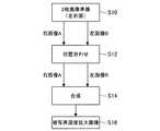
図2は、被写界深度拡大補正処理部220における基本的な補正手順を示す模式図であって、主として被写界深度拡大処理部224で行われる処理を示している。図2の処理を行う前提として、撮像画像取得部222が立体視/被写界深度拡大切替判定部210から左右1対の画像情報を取得する。先ず、ステップS10では、立体視/被写界深度拡大切替判定部210から送られた左右1対の右眼用画像及び左眼用画像(右画像A、左画像B)を準備する。この2枚の画像は、フォーカス位置が異なるものであっても良い。3. 3. ) Processing in the depth of field enlargement correction processing unit 3.1. ) Basic processing in the depth of field enlargement correction processing unit FIG. 2 is a schematic diagram showing a basic correction procedure in the depth of field enlargement
また、ステップS10では、左右画像の各々でEDoF処理(被写界深度拡大処理)を行う。EDoF処理の詳細については、後述する。 Further, in step S10, EDoF processing (depth of field enlargement processing) is performed on each of the left and right images. Details of the EDoF process will be described later.
次のステップS12では、右画像Aと左画像Bの位置合わせを行う。具体的には、右画像Aと左画像Bの共通部を抜き出し、形状補正を行うことで、位置合わせを行う。位置合わせの際には、視差を相殺するような処理を行う。 In the next step S12, the right image A and the left image B are aligned. Specifically, the common portion of the right image A and the left image B is extracted and shape correction is performed to perform alignment. At the time of alignment, processing is performed to offset the parallax.
次のステップS14では、位置合わせした右画像Aと左画像Bを合成する。この際、デプス位置(奥行き位置)に依存して、右画像Aと左画像Bの合成比率を変える。これにより、次のステップS16において、2次元の被写界深度拡大画像が得られる。 In the next step S14, the aligned right image A and left image B are combined. At this time, the composition ratio of the right image A and the left image B is changed depending on the depth position (depth position). As a result, in the next step S16, a two-dimensional depth-of-field enlarged image is obtained.
図3は、図2のステップS10において、フォーカス位置が異なる右画像A、左画像Bを取得した場合を示す模式図である。図3に示すように、右画像Aは中央の被写体aに合焦点しており、周囲(背景)の被写体bはボケている。一方、左画像Bは中央の被写体aがボケており、周囲の被写体bに合焦している。 FIG. 3 is a schematic view showing the case where the right image A and the left image B having different focus positions are acquired in step S10 of FIG. As shown in FIG. 3, the right image A is focused on the central subject a, and the surrounding (background) subject b is out of focus. On the other hand, in the left image B, the central subject a is out of focus and is in focus on the surrounding subject b.
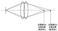
図4は、右画像Aの合焦位置と左画像Bの合焦位置を示す模式図である。図4に示すように、右画像Aは被写体aの位置で合焦しており、左画像Bは被写体bの位置で合焦している。 FIG. 4 is a schematic view showing the in-focus position of the right image A and the in-focus position of the left image B. As shown in FIG. 4, the right image A is in focus at the position of the subject a, and the left image B is in focus at the position of the subject b.
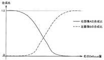
ステップS12の位置合わせを行った後、ステップS14では、デプス位置に応じて右画像Aと左画像Bの合成比率を変える。中央の被写体aの位置では右画像Aの比率を高くし、周囲の被写体bでは左画像Bの比率を高くする。図5は、デプス位置に応じた合成比率を示す特性図である。デプス位置が奥になるほど(背景に近づくほど)、右画像Aの比率RAが低くなり、左画像Bの比率RBが大きくなる。また、デプス位置が手前になるほど、右画像Aの比率RAが高くなり、左画像Bの比率RBが低くなる。なお、RB=1−RAとすることができる。メインの画像は、中央部で合焦している右画像Aとなる。デプスマップに基づいて、図5に従って右画像Aと左画像Bを合成することで、空間的に合成比率を変更することが可能となり、中央と周囲の双方で合焦した2次元の被写界深度拡大画像を得ることができる。After aligning in step S12, in step S14, the composition ratio of the right image A and the left image B is changed according to the depth position. At the position of the central subject a, the ratio of the right image A is increased, and at the position of the surrounding subject b, the ratio of the left image B is increased. FIG. 5 is a characteristic diagram showing the composition ratio according to the depth position. The deeper the depth position (closer to the background), thelower the ratio R A of the right image A and the largerthe ratio R B of the left image B. Further, as the depth position is closer to the front, the ratio RA of the right image A becomes higher and the ratio RB of the left image B becomes lower.Incidentally, it is possible toR B = 1-RA. The main image is the right image A, which is in focus at the center. By synthesizing the right image A and the left image B according to FIG. 5 based on the depth map, it is possible to change the composition ratio spatially, and the two-dimensional field in focus at both the center and the periphery. A depth-of-field enlarged image can be obtained.
以下では、図2のステップS10の2枚画像準備、ステップS12の位置合わせ、ステップS16の2枚画像の合成について、詳細に説明する。 In the following, the preparation of the two images in step S10 in FIG. 2, the alignment in step S12, and the composition of the two images in step S16 will be described in detail.
3.2.)2枚画像準備
3.2.1.)左右画像いずれかでEDoFする処理
被写界深度拡大補正処理部220では、右画像Aと左画像Bのそれぞれで単独にEDoF処理を行うことができる。この場合、左右どちらかの片眼の画1枚だけで、EDoFを実施する。片眼の画像1枚を利用したEDoF処理には、以下に示す複数のバリエーションがある。この場合、片眼だけでもEDoFは完成するので、合焦位置が異なる2枚の画像を用意することはダミーとなり、もう1枚の画はEDoFした画のコピーとしても良い。3.2. ) Preparation of 2 images 3.2.1. ) Processing to perform EDoF on either the left or right image The depth of field enlargement
3.2.1.1.)Depth+PSFデータによるデコンボリューション(逆重畳積分、逆重畳:Deconvolution)
この方法では、図6に示すような空間距離情報(デプスマップ:depth map)と、図7に示すような、レンズのボケ方を示すPSF(Point Spread Function)の距離による変化特性を用いる。図6では、左側に撮像画像を、右側にデプス情報を示している。右側のデプス情報では、濃度が黒いほど被写体が遠く(奥)にあり、濃度が白いほど被写体が近く(手前)にあることを示している。3.2.1.1. ) Deconvolution by Depth + PSF data (deconvolution, deconvolution)
In this method, the spatial distance information (depth map) as shown in FIG. 6 and the change characteristic depending on the distance of PSF (Point Spread Function) indicating how the lens is blurred as shown in FIG. 7 are used. In FIG. 6, the captured image is shown on the left side and the depth information is shown on the right side. In the depth information on the right side, the darker the density, the farther (back) the subject is, and the whiter the density, the closer (front) the subject is.
図6に示すデプス情報は、視差情報から得ることができる。ブロックマッチングの結果、左右画像の視差情報をピクセル数として求めることができ、視差情報を距離情報に変換することができる。従って、図6に示すデプス情報は、視差情報、距離情報によって求めることができる。 The depth information shown in FIG. 6 can be obtained from the parallax information. As a result of block matching, the parallax information of the left and right images can be obtained as the number of pixels, and the parallax information can be converted into distance information. Therefore, the depth information shown in FIG. 6 can be obtained from the parallax information and the distance information.
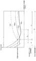
また、図7では、合焦位置に対して、デプスに応じてボケが発生する様子を示しており、合焦位置から離れるほどボケが大きくなる様子を示している。図7に示すように、デプスに応じたボケ量は、Pill Box Functionによるぼけ関数、2次元Gauss関数によるぼけ関数で近似することができる。図7に示すPSFの情報は、カメラヘッド100の光学系の仕様から予め求められており、被写界深度拡大補正処理部220に入力される。なお、PSFの情報は、カメラヘッド100から取得しても良い。 Further, FIG. 7 shows a state in which blurring occurs according to the depth with respect to the focusing position, and shows a state in which the blurring increases as the distance from the focusing position increases. As shown in FIG. 7, the amount of blur according to the depth can be approximated by the blur function by the Pil Box Function and the blur function by the two-dimensional Gauss function. The PSF information shown in FIG. 7 is obtained in advance from the specifications of the optical system of the
被写界深度拡大補正処理部220は、距離情報及びPSF情報に基づいて、EDoF処理を行う。この際、視差情報、距離情報は、カメラヘッド100側で算出しても良いし、被写界深度拡大補正処理部220側で算出しても良い。図6及び図7の情報が取得されていれば、デプス位置に応じたボケ量が判るため、撮像された画像のぼけている部分に逆PSFフィルタ処理(deconvolution)を行うことにより、ボケを除去したEDoF画像を得ることができる。 The depth of field enlargement
3.2.1.2.)R/G/Bチャネル間の軸上色収差利用
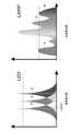
レンズの光学特性に応じて、入力波長光の差分によって合焦位置が異なるという現象(軸上色収差)が発生する。このため、カラー画像のR,G,Bの各々のチャネルの画像は合焦位置が異なっている。この特性を利用し、図8及び図9に示すように、各チャネルの高周波成分をデプス(depth)に応じて他チャネルに合成(sharpness transfer)して、EDoF画像を得ることができる。3.2.1.2. ) Utilization of axial chromatic aberration between R / G / B channels A phenomenon (axial chromatic aberration) occurs in which the focusing position differs depending on the difference in input wavelength light depending on the optical characteristics of the lens. Therefore, the focus positions of the R, G, and B channel images of the color image are different. Utilizing this characteristic, as shown in FIGS. 8 and 9, an EDoF image can be obtained by synthesizing the high frequency component of each channel into another channel according to the depth.
図8に示すように、被写界深度拡大補正処理部220は、最もシャープな色の画像から高周波成分を抽出する。また、図7に示したようなデプス情報を別途抽出しておく。そして、抽出した高周波成分を、最もシャープな色の画像のデプス位置の他の色の画像に合成する。これにより、図9に示すように、R,G,Bの各々のチャネルの画像の被写界深度は、それぞれDR,DG,DBであるが、デプス位置に応じて最もシャープなチャンネルの高周波成分を合成することで、EDoF処理後の被写界深度DEを大幅に拡大することができる。As shown in FIG. 8, the depth of field enlargement
しかしながら、この方法を利用する際に、図10の右図に示す広波長光源を利用すると、最もシャープなチャネルの画像情報の中に、合焦している波長信号成分と合焦していない波長信号成分の混在率が高くなるため、高周波成分の抽出度合が減り、他チャネルへ高周波成分を合成しても、被写界深度拡大の効果が十分得られないことがある。そのような場合に、図10の左図に示すLEDやLaserの様なより狭帯域の照明に切り替えることにより、より合焦している信号成分を多く抽出することができるため、被写界深度拡大効果を高めることができる。このため、照明制御部240は、照明装置400を制御して図10に示すような狭波長光源、または広波長光源による被写体への照射を行う。このように、光源を連動させて、光源を狭波長にすることにより、より軸上色収差を出して、EDoFの度合いを上げることも可能である。これにより、より広い被写界深度のEDoF画像を得ることが可能となる。 However, when using this method, if the wide wavelength light source shown in the right figure of FIG. 10 is used, the wavelengths that are in focus and the wavelengths that are not in focus are included in the image information of the sharpest channel. Since the mixing ratio of signal components is high, the degree of extraction of high-frequency components is reduced, and even if high-frequency components are combined with other channels, the effect of increasing the depth of field may not be sufficiently obtained. In such a case, by switching to a narrower band illumination such as the LED or Laser shown on the left side of FIG. 10, more focused signal components can be extracted, so that the depth of field can be extracted. The expansion effect can be enhanced. Therefore, the
3.2.1.3.)フレームシーケンシャル(FS)による時間差合焦位置ずらし
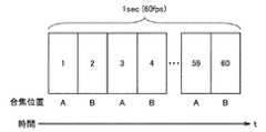
フレームレート(Frame rate)は半分になるが、図11に示すように、各フレーム毎に時間をずらして合焦位置A,Bを変えて撮影すれば、合焦位置をずらして撮影した2枚の画像を用意できることになり、その2枚を合成すればEDoF画像を得ることができる。合成方法として、図4及び図5と同様の方法を用いることができ、一例として合焦位置Aを図4の被写体aの位置とし、合焦位置Bを図4の被写体bの位置とする。3.2.1.1. ) Time-lag focusing position shift due to frame sequential (FS) The frame rate is halved, but as shown in FIG. 11, the time is shifted for each frame and the focusing positions A and B are changed for shooting. For example, it is possible to prepare two images taken by shifting the focusing position, and an EDoF image can be obtained by synthesizing the two images. As a synthesis method, the same method as in FIGS. 4 and 5 can be used. As an example, the focusing position A is the position of the subject a in FIG. 4, and the focusing position B is the position of the subject b in FIG.
なお、上述した例以外にも、画像1枚からEDoF処理を行う公知の各種方法を用いることができる。デプス情報が得られていれば、被写体距離に応じたデコンボリューションが可能である。 In addition to the above-mentioned examples, various known methods for performing EDoF processing from one image can be used. If depth information is obtained, deconvolution according to the subject distance is possible.
3.2.2.)左右画像各々でEDoFする処理
片眼の画像で単独でEDoF処理を行う場合、パンフォーカス(全体的に焦点が合っている画)が作れるわけではなく、元々の合焦位置からの合焦範囲がある程度拡大する効果がある。左右画像を用いて撮像時に合焦位置をずらして撮影し、且つ片眼画像の各々で上記のEDoF処理を行うことにより、中心合焦位置が異なる2種類の単独EDoF画像を得ることができる。このEDoF画像を、図12に示すように、更に位置合わせして合成することにより、片眼画像の単独でEDoF処理した場合よりも更に合焦位置が拡大されたEDoF画像(スーパーEDoF画像)を得ることが可能となる。3.2.2. ) EDoF processing for each of the left and right images When EDoF processing is performed independently for one eye image, it is not possible to create pan focus (an image that is in focus as a whole), and the focusing range from the original focusing position. Has the effect of expanding to some extent. By using the left and right images to take pictures with the focus position shifted at the time of imaging and performing the above EDoF processing on each of the monocular images, it is possible to obtain two types of independent EDoF images having different central focus positions. As shown in FIG. 12, by further aligning and synthesizing this EDoF image, an EDoF image (super EDoF image) in which the focusing position is further enlarged as compared with the case where the one-eye image alone is subjected to EDoF processing can be obtained. It becomes possible to obtain.
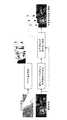
図12に示す例では、上述した手法により左右画像のそれぞれで単独にEDoF処理を行っている。図12において、ステップS10〜S16は図2のステップS10〜S16に対応している。図12のステップS10では、左右画像の合焦位置をずらして右画像Aと左画像Bを準備し、右画像Aと左画像Bのそれぞれについて単独でEDoF処理を行い、右EDoF画像、左EDoF画像を得る。 In the example shown in FIG. 12, EDoF processing is independently performed on each of the left and right images by the above-mentioned method. In FIG. 12, steps S10 to S16 correspond to steps S10 to S16 of FIG. In step S10 of FIG. 12, the right image A and the left image B are prepared by shifting the focusing positions of the left and right images, EDoF processing is performed independently for each of the right image A and the left image B, and the right EDoF image and the left EDoF are performed independently. Get an image.
その後、ステップS12で位置合わせを行い、ステップS14で左右画像を合成することで、ステップS16では、図2よりも被写界深度が拡大されたスーパーEDoF画像を得ることができる。これにより、単独EDoFよりもより深度の深いEDoFが実現可能となる。なお、ステップS12〜S16の詳細は後述する。 After that, the alignment is performed in step S12, and the left and right images are combined in step S14, so that in step S16, a super EDoF image having a wider depth of field than in FIG. 2 can be obtained. This makes it possible to realize an EDoF having a deeper depth than a single EDoF. The details of steps S12 to S16 will be described later.
以上のように、右画像Aと左画像Bのフォーカス位置を異ならせた上で、それぞれに単独にEDoF処理を行った後、上述した手法で両者を合成することで、被写界深度をより拡大することが可能となる。 As described above, after different focus positions of the right image A and the left image B, EDoF processing is performed independently for each, and then the two are combined by the above-mentioned method to increase the depth of field. It will be possible to expand.
3.3.)位置合わせ
左右の画像には視差が存在するため、単に合成すると画像上にギャップが生じる。このため、2枚の画像の位置を合わせて共通画角を切り出す処理を行い、左右視差を相殺するような位置合わせ処理を行う(図2及び図12のステップS14)。図13は、位置合わせ処理を示すフローチャートである。先ず、ステップS20では、2枚の画像から位置合わせの指標となる、特徴点を抽出する。次のステップS22では、特徴点を利用して位置合わせを行う。ここでは、例えば特許第4136044号に記載されているような、特徴量を使って位置を合わせる方法などが利用できる。指標となるいくつかの特徴点を抽出できたら、それらの位置を合わせるために、ステップS24では、例えばアフィン変換のような手法を用いて、左右画像を微小に変形させて形状フィッティングを行って補正する。また、ステップS24では、必要に応じて、周辺画素で埋める等のオクルージョンの補正も実施する。その後、ステップS26では、図14に示すような左右の画角の共通部分を切り出して、左右の画像差分がぼけ差分以外なるべく少ない状態になるように画像処理を行う。3.3. ) Alignment Since there is parallax between the left and right images, a gap will occur on the image if simply combined. Therefore, a process of aligning the positions of the two images to cut out a common angle of view is performed, and an alignment process of canceling the left-right parallax is performed (step S14 of FIGS. 2 and 12). FIG. 13 is a flowchart showing the alignment process. First, in step S20, feature points, which are indicators of alignment, are extracted from the two images. In the next step S22, the alignment is performed using the feature points. Here, for example, a method of aligning positions using a feature amount as described in Japanese Patent No. 4136044 can be used. After extracting some feature points that serve as indicators, in step S24, in order to align them, the left and right images are slightly deformed and shape-fitted to correct them by using a technique such as affine transformation. do. Further, in step S24, if necessary, correction of occlusion such as filling with peripheral pixels is also performed. After that, in step S26, a common portion of the left and right angles of view as shown in FIG. 14 is cut out, and image processing is performed so that the difference between the left and right images is as small as possible other than the blur difference.
なお、片眼画像の単独でEDoF処理する場合は、他方の画像はEDoF処理した画像のコピーで済むため、位置合わせは不要である。 When the EDoF processing is performed on the one-eye image alone, the other image can be a copy of the EDoF-processed image, so that the alignment is not necessary.
3.4.)2枚画像の合成(1枚の被写界深度拡大画像の作成)
3.4.1.)デプスマップ(Depth map)を利用した合成
デプスマップが取得できている場合、図5に示したように、左右の画像の合成比率をデプス値に応じて決定し、画像の空間ピクセル(pixel)毎に合成比率を変調して合成画像を作成する。図5の例であれば、中央の被写体付近ではほとんど右画像Aの画像情報が使われ、背景に関しては左画像Bの画像情報が使われる。中間の距離にある被写体に関しては、合成比グラフを参照して、左画像B、右画像Aの画像情報が程よく合成されるようにする。合成比関数の遷移部分の設計は経験値に基づいて行われても良いし、左画像B〜右画像Aへの急激な遷移が発生しないよう、シグモイド関数など数学的に滑らかな曲線でつないでも良い。3.4. ) Combining two images (creating one image with an enlarged depth of field)
3.4.1. ) Composite using the depth map When the depth map can be obtained, as shown in FIG. 5, the composite ratio of the left and right images is determined according to the depth value, and the spatial pixel of the image is determined. A composite image is created by modulating the composite ratio each time. In the example of FIG. 5, the image information of the right image A is mostly used in the vicinity of the central subject, and the image information of the left image B is used for the background. For a subject at an intermediate distance, the image information of the left image B and the right image A is appropriately combined with reference to the composition ratio graph. The transition part of the composite ratio function may be designed based on empirical values, or it may be connected by a mathematically smooth curve such as a sigmoid function so that a sudden transition from the left image B to the right image A does not occur. good.
3.4.2.)デフォーカスマップ(Defocus map)を利用した合成
デプスマップが取得できない場合であっても、撮像できている画像の特徴量からボケ量を推定し、それを指標として画像を合成することができる。左右いずれか一方の画像から空間的なblur変化を推定して、デフォーカスマップを作成する公知の方法が知られている。デフォーカスマップが作成できれば、それを参照して、図15に示すような変調を実施する。すなわち、デフォーカス量が少ないところはデフォーカスマップの元になった画像(図15の例では右画像A)の合成比を上げ、そうでない場所ではもう片方の合成比を上げることで、全体として合焦箇所が多い画像を得ることができる。なお、デフォーカス量とデプス量の違いは、デプス量が合焦位置に対して手前であるかまたは奥であるかの情報を有しているのに対し、デフォーカス量はその情報は有しておらず、合焦位置からの差分量を示す情報のみである点である。この方法はデプスマップを利用しないため、デプス検出の計算負荷を最小限に抑えることができ、また距離センサが不要となるメリットがある。3.4.2. ) Synthesis using the defocus map (Defocus map) Even when the depth map cannot be obtained, the amount of blur can be estimated from the feature amount of the image that can be captured, and the image can be synthesized using it as an index. A known method for creating a defocus map by estimating a spatial blur change from either the left or right image is known. If a defocus map can be created, the modulation as shown in FIG. 15 is performed with reference to it. That is, by increasing the composition ratio of the image (right image A in the example of FIG. 15) that is the basis of the defocus map where the amount of defocus is small, and increasing the composition ratio of the other image where it is not, as a whole. An image with many in-focus points can be obtained. The difference between the defocus amount and the depth amount has information on whether the depth amount is in front of or behind the in-focus position, whereas the defocus amount has that information. The point is that it is only information indicating the amount of difference from the in-focus position. Since this method does not use a depth map, the calculation load for depth detection can be minimized, and there is an advantage that a distance sensor is not required.
上記以外にも、複数画像から被写界深度の深い画像を合成する方法であれば、公知の技術を適用可能である。例えば、複数画像からの合成により被写界深度を拡大する方法では、明示的にデプスマップやデフォーカスマップを利用しなくても、画像さえあればフォーカスの合った合成画像を作成可能である。本実施形態におけるEDoF処理とは、複数画像から被写界深度拡大画像を作成する公知の全ての方法を含む概念である。 In addition to the above, a known technique can be applied as long as it is a method of synthesizing an image having a deep depth of field from a plurality of images. For example, in the method of expanding the depth of field by compositing from a plurality of images, it is possible to create a composite image in focus as long as there is an image without explicitly using a depth map or a defocus map. The EDoF process in the present embodiment is a concept including all known methods for creating a depth-of-field enlarged image from a plurality of images.
以上説明したように本実施形態によれば、状況に応じて3次元の立体視画像による観察か、又は2次元の被写界深度拡大画像による観察を行うことができる。従って、例えば得次元画像の観察により眼精疲労が生じた場合、手前から奥行きまでの広い領域の画像情報を得たい場合など、状況に応じて2次元の被写界深度拡大画像による観察を行うことが可能となる。 As described above, according to the present embodiment, it is possible to perform observation with a three-dimensional stereoscopic image or observation with a two-dimensional depth-of-field enlarged image depending on the situation. Therefore, for example, when eyestrain occurs due to observation of a obtained dimensional image, or when it is desired to obtain image information of a wide area from the front to the depth, observation is performed using a two-dimensional depth-of-field enlarged image depending on the situation. It becomes possible.
以上、添付図面を参照しながら本開示の好適な実施形態について詳細に説明したが、本開示の技術的範囲はかかる例に限定されない。本開示の技術分野における通常の知識を有する者であれば、特許請求の範囲に記載された技術的思想の範疇内において、各種の変更例または修正例に想到し得ることは明らかであり、これらについても、当然に本開示の技術的範囲に属するものと了解される。 Although the preferred embodiments of the present disclosure have been described in detail with reference to the accompanying drawings, the technical scope of the present disclosure is not limited to such examples. It is clear that a person having ordinary knowledge in the technical field of the present disclosure can come up with various modifications or modifications within the scope of the technical ideas described in the claims. Of course, it is understood that the above also belongs to the technical scope of the present disclosure.
また、本明細書に記載された効果は、あくまで説明的または例示的なものであって限定的ではない。つまり、本開示に係る技術は、上記の効果とともに、または上記の効果に代えて、本明細書の記載から当業者には明らかな他の効果を奏しうる。 In addition, the effects described herein are merely explanatory or exemplary and are not limited. That is, the techniques according to the present disclosure may exhibit other effects apparent to those skilled in the art from the description herein, in addition to or in place of the above effects.
なお、以下のような構成も本開示の技術的範囲に属する。
(1) 左眼用画像又は右眼用画像の撮影状況に関する情報を取得する撮影状況取得部と、
前記撮影状況に関する情報に応じて、前記左眼用画像又は前記右眼用画像に対して立体視画像処理を行うか、又は前記左眼用画像及び前記右眼用画像の少なくとも一方による2次元の被写界深度拡大処理を行うかを判定する判定部と、
を備える、画像処理装置。
(2) 前記撮影状況に関する情報は、前記左眼用画像又は前記右眼用画像を撮像した際の光学ズーム値、前記左眼用画像又は前記右眼用画像を撮像した際の電子ズーム値、前記左眼用画像と前記右眼用画像の視差情報、前記左眼用画像又は前記右眼用画像の被写体までの距離情報、及びユーザによる操作情報の少なくともいずれかである、前記(1)に記載の画像処理装置。
(3) 更に、被写界深度拡大処理部を備え、
前記被写界深度拡大処理部は、前記判定部により被写界深度拡大処理を行うと判定された場合に、前記左眼用画像及び前記右眼用画像の少なくとも1つを用いて被写界深度拡大画像を生成する、前記(1)又は(2)に記載の画像処理装置。
(4) 前記被写界深度拡大処理部は、前記左眼用画像と前記右眼用画像の視差角が2度以上の場合に前記被写界深度拡大画像を生成する、前記(3)に記載の画像処理装置。
(5) 前記被写界深度拡大処理部は、前記左眼用画像及び前記右眼用画像の少なくとも1つについて、デプス量に応じたぼけ関数に基づいて逆変換を行うことで前記被写界深度拡大画像を生成する、前記(3)に記載の画像処理装置。
(6) 前記被写界深度拡大処理部は、合焦位置の異なるR,G,Bの各色の画像のうちデプス位置に応じて最も高周波成分の多い画像を同じデプス位置の他の色の画像に合成することで前記被写界深度拡大画像を生成する、前記(3)に記載の画像処理装置。
(7) 更に、照明制御部を備え、
前記照明制御部は、前記R,G,Bの各色の画像の合焦位置を調整するために照明を制御する、前記(6)に記載の画像処理装置。
(8) 前記被写界深度拡大処理部は、フレーム毎に異なる合焦位置で撮像された複数の画像を合成することで前記被写界深度拡大画像を生成する、前記(3)に記載の画像処理装置。
(9) 前記被写界深度拡大処理部は、異なる合焦位置で撮像された前記左眼用画像及び前記右眼用画像のそれぞれについて被写界深度を拡大し、被写界深度が拡大された前記左眼用画像及び前記右眼用画像を合成することで前記被写界深度拡大画像を生成する、前記(3)に記載の画像処理装置。
(10) 前記被写界深度拡大処理部は、デプス位置又はデフォーカス位置に応じて前記左眼用画像及び前記右眼用画像の合成比率を変える、前記(9)に記載の画像処理装置。
(11) 前記被写界深度拡大処理部は、前記左眼用画像及び前記右眼用画像の位置合わせをして前記合成を行う、前記(9)に記載の画像処理装置。
(12) 前記被写界深度拡大処理部は、前記左眼用画像及び前記右眼用画像の共通範囲を切り出して前記合成を行う、前記(9)に記載の画像処理装置。
(13) 左眼用画像又は右眼用画像の撮影状況に関する情報を取得することと、
前記撮影状況に関する情報に応じて、前記左眼用画像又は前記右眼用画像に対して立体視画像処理を行うか、又は前記左眼用画像及び前記右眼用画像の少なくとも一方による2次元の被写界深度拡大処理を行うかを判定することと、
を備える、画像処理方法。
(14) 左眼用画像又は右眼用画像の撮影状況に関する情報を取得する手段、
前記撮影状況に関する情報に応じて、前記左眼用画像又は前記右眼用画像に対して立体視画像処理を行うか、又は前記左眼用画像及び前記右眼用画像の少なくとも一方による2次元の被写界深度拡大処理を行うかを判定する手段、
としてコンピュータを機能させるためのプログラム。
(15) 左眼用画像及び右眼用画像を撮像する撮像装置と、
左眼用画像又は右眼用画像の撮影状況に関する情報を取得する取得部と、前記撮影状況に関する情報に応じて、前記左眼用画像又は前記右眼用画像に対して立体視画像処理を行うか、又は前記左眼用画像及び前記右眼用画像の少なくとも一方による2次元の被写界深度拡大処理を行うかを判定する判定部と、を有する、画像処理装置と、
を備える、撮像システム。
(16) 左眼用画像及び右眼用画像を取得する撮像画像取得部と、
前記左眼用画像及び前記右眼用画像のそれぞれについて被写界深度を拡大し、被写界深度が拡大された前記左眼用画像及び前記右眼用画像を合成することで被写界深度拡大画像を生成する被写界深度拡大処理部と、
を備える、画像処理装置。
(17) 前記被写界深度拡大処理部は、デプス位置又はデフォーカス位置に応じて前記左眼用画像及び前記右眼用画像の合成比率を変える、請求項16に記載の画像処理装置。
(18) 前記被写界深度拡大処理部は、前記左眼用画像及び前記右眼用画像の位置合わせをし、前記左眼用画像及び前記右眼用画像の共通範囲を切り出して前記合成を行う、前記(16)に記載の画像処理装置。
(19) 左眼用画像及び右眼用画像を取得することと、
前記左眼用画像及び前記右眼用画像のそれぞれについて被写界深度を拡大し、被写界深度が拡大された前記左眼用画像及び前記右眼用画像を合成することで被写界深度拡大画像を生成することと、
を備える、画像処理方法。
(20) 左眼用画像及び右眼用画像を取得することと、
前記左眼用画像及び前記右眼用画像のそれぞれについて被写界深度を拡大し、被写界深度が拡大された前記左眼用画像及び前記右眼用画像を合成することで被写界深度拡大画像を生成することと、
としてコンピュータを機能させるためのプログラム。The following configurations also belong to the technical scope of the present disclosure.
(1) A shooting status acquisition unit that acquires information on the shooting status of the left eye image or the right eye image, and
Depending on the information regarding the shooting situation, the left eye image or the right eye image is subjected to stereoscopic image processing, or the left eye image and at least one of the right eye images are two-dimensional. A determination unit that determines whether to perform depth-enhancing processing, and
An image processing device.
(2) The information regarding the shooting situation includes an optical zoom value when the left eye image or the right eye image is captured, an electronic zoom value when the left eye image or the right eye image is captured, and the like. At least one of the disparity information between the left-eye image and the right-eye image, the distance information of the left-eye image or the right-eye image to the subject, and the operation information by the user, according to the above (1). The image processing apparatus described.
(3) Further, a depth of field expansion processing unit is provided.
When the determination unit determines that the depth of field enlargement processing is performed, the depth of field enlargement processing unit uses at least one of the left eye image and the right eye image to provide a field of view. The image processing apparatus according to (1) or (2) above, which generates a depth-of-field enlarged image.
(4) The depth-of-field enlargement processing unit generates the depth-of-field enlargement image when the parallax angle between the left-eye image and the right-eye image is 2 degrees or more. The image processing apparatus described.
(5) The depth-of-field enlargement processing unit performs inverse conversion on at least one of the left-eye image and the right-eye image based on a blur function according to the depth amount, thereby causing the depth of field. The image processing apparatus according to (3) above, which generates a depth-of-field enlarged image.
(6) The depth-of-field enlargement processing unit converts an image having the most high-frequency components according to the depth position among images of R, G, and B colors having different focusing positions into an image of another color having the same depth position. The image processing apparatus according to (3) above, which generates the depth-of-field enlarged image by synthesizing the image.
(7) Further, a lighting control unit is provided.
The image processing device according to (6) above, wherein the illumination control unit controls illumination in order to adjust the focusing position of the image of each color of R, G, and B.
(8) The depth of field enlargement processing unit generates the depth of field enlargement image by synthesizing a plurality of images captured at different focusing positions for each frame, according to the above (3). Image processing device.
(9) The depth-of-field enlargement processing unit expands the depth of field for each of the left-eye image and the right-eye image captured at different focusing positions, and the depth of field is expanded. The image processing apparatus according to (3), wherein the depth-of-field enlarged image is generated by synthesizing the left-eye image and the right-eye image.
(10) The image processing apparatus according to (9), wherein the depth of field enlargement processing unit changes the composition ratio of the left eye image and the right eye image according to the depth position or the defocus position.
(11) The image processing apparatus according to (9), wherein the depth of field enlargement processing unit aligns the left eye image and the right eye image and performs the composition.
(12) The image processing apparatus according to (9), wherein the depth-of-field enlargement processing unit cuts out a common range between the left-eye image and the right-eye image and performs the synthesis.
(13) Acquiring information on the shooting status of the left eye image or the right eye image, and
Depending on the information regarding the shooting situation, the left eye image or the right eye image is subjected to stereoscopic image processing, or the left eye image and at least one of the right eye images are two-dimensional. Determining whether to perform depth of field expansion processing and
An image processing method.
(14) Means for acquiring information on the shooting status of the left eye image or the right eye image,
Depending on the information regarding the shooting situation, the left eye image or the right eye image is subjected to stereoscopic image processing, or the left eye image and at least one of the right eye images are two-dimensional. Means for determining whether to perform depth of field expansion processing,
A program to make your computer work as.
(15) An imaging device that captures images for the left eye and images for the right eye, and
A stereoscopic image processing is performed on the left eye image or the right eye image according to the acquisition unit that acquires information on the shooting status of the left eye image or the right eye image and the information on the shooting status. An image processing apparatus having a determination unit for determining whether to perform a two-dimensional depth of view expansion process by at least one of the left eye image and the right eye image.
An imaging system.
(16) An image acquisition unit that acquires an image for the left eye and an image for the right eye, and
The depth of field is expanded for each of the left eye image and the right eye image, and the depth of field is combined by synthesizing the left eye image and the right eye image with the expanded depth of field. Depth of field enlargement processing unit that generates an enlarged image,
An image processing device.
(17) The image processing apparatus according to claim 16, wherein the depth of field enlargement processing unit changes the composition ratio of the left eye image and the right eye image according to the depth position or the defocus position.
(18) The depth-of-field enlargement processing unit aligns the image for the left eye and the image for the right eye, cuts out a common range of the image for the left eye and the image for the right eye, and performs the composition. The image processing apparatus according to (16) above.
(19) Acquiring an image for the left eye and an image for the right eye,
The depth of field is expanded for each of the left eye image and the right eye image, and the depth of field is combined by synthesizing the left eye image and the right eye image with the expanded depth of field. Generating a magnified image and
An image processing method.
(20) Acquiring an image for the left eye and an image for the right eye,
The depth of field is expanded for each of the left eye image and the right eye image, and the depth of field is combined by synthesizing the left eye image and the right eye image with the expanded depth of field. Generating a magnified image and
A program to make your computer work as.
100 カメラヘッド
200 画像処理装置
210 立体視/被写界深度拡大切替判定部
212 撮影状況取得部
214 判定部
220 被写界深度拡大補正処理部
222 撮像画像取得部
224 被写界深度拡大処理部
240 照明制御部100
Claims (19)
Translated fromJapanese前記撮影状況に関する情報に応じて、前記左眼用画像及び前記右眼用画像に対して立体視画像処理を行うか、又は前記左眼用画像及び前記右眼用画像の少なくとも一方による2次元の被写界深度拡大処理を行うかを判定する判定部と、
を備え、
前記撮影状況に関する情報は、前記左眼用画像及び前記右眼用画像を撮像した際の光学ズーム値、前記左眼用画像及び前記右眼用画像を撮像した際の電子ズーム値、前記左眼用画像と前記右眼用画像の視差情報、前記左眼用画像及び前記右眼用画像の被写体までの距離情報、及びユーザによる操作情報の少なくともいずれかである、
画像処理装置。A photographing condition acquisition section that acquires information about photographing conditions ofthe left-eye image andthe right-eye image by thepair of left and right stereoscopic imagingdevice for imaging the left-eye image and the right-eye image,
Depending on the information regarding the shooting situation, the left eye image and the right eye image are subjected to stereoscopic image processing, or the left eye image and at least one of the right eye images are two-dimensional. A determination unit that determines whether to perform depth-enhancing processing, and
With
The information regarding the shooting situation includes an optical zoom value when the left eye image and the right eye image are captured, an electronic zoom value when the left eye image and the right eye image are captured, and the left eye. At least one of the disparity information between the image for the right eye and the image for the right eye, the distance information for the image for the left eye and the image for the right eye to the subject, and the operation information by the user.
Image processing device.
前記被写界深度拡大処理部は、前記判定部により被写界深度拡大処理を行うと判定された場合に、前記左眼用画像及び前記右眼用画像の少なくとも1つを用いて被写界深度拡大画像を生成する、請求項1に記載の画像処理装置。Furthermore, it is equipped with a depth of field expansion processing unit.
When the determination unit determines that the depth of field enlargement processing is performed, the depth of field enlargement processing unit uses at least one of the left eye image and the right eye image to provide a field of view. The image processing apparatus according to claim 1, which generates a depth-of-field enlarged image.
前記照明制御部は、前記R,G,Bの各色の画像の合焦位置を調整するために照明を制御する、請求項5に記載の画像処理装置。In addition, it is equipped with a lighting control unit.
The image processing apparatus according to claim 5, wherein the illumination control unit controls illumination in order to adjust the focusing position of the image of each color of R, G, and B.
前記撮影状況に関する情報に応じて、前記左眼用画像及び前記右眼用画像に対して立体視画像処理を行うか、又は前記左眼用画像及び前記右眼用画像の少なくとも一方による2次元の被写界深度拡大処理を行うかを判定することと、
を備え、
前記撮影状況に関する情報は、前記左眼用画像及び前記右眼用画像を撮像した際の光学ズーム値、前記左眼用画像及び前記右眼用画像を撮像した際の電子ズーム値、前記左眼用画像と前記右眼用画像の視差情報、前記左眼用画像及び前記右眼用画像の被写体までの距離情報、及びユーザによる操作情報の少なくともいずれかである、
画像処理方法。And to obtain information about the shooting conditions ofthe left-eye image andthe right-eye image by thepair of left and right stereoscopic imagingdevice for imaging the left-eye image and the right-eye image,
Depending on the information regarding the shooting situation, the left eye image and the right eye image are subjected to stereoscopic image processing, or the left eye image and at least one of the right eye images are two-dimensional. Determining whether to perform depth of field expansion processing and
With
The information regarding the shooting situation includes an optical zoom value when the left eye image and the right eye image are captured, an electronic zoom value when the left eye image and the right eye image are captured, and the left eye. At least one of the disparity information between the image for the right eye and the image for the right eye, the distance information for the image for the left eye and the image for the right eye to the subject, and the operation information by the user.
Image processing method.
前記撮影状況に関する情報に応じて、前記左眼用画像及び前記右眼用画像に対して立体視画像処理を行うか、又は前記左眼用画像及び前記右眼用画像の少なくとも一方による2次元の被写界深度拡大処理を行うかを判定する手段、
としてコンピュータを機能させ、
前記撮影状況に関する情報は、前記左眼用画像及び前記右眼用画像を撮像した際の光学ズーム値、前記左眼用画像及び前記右眼用画像を撮像した際の電子ズーム値、前記左眼用画像と前記右眼用画像の視差情報、前記左眼用画像及び前記右眼用画像の被写体までの距離情報、及びユーザによる操作情報の少なくともいずれかである、
プログラム。Means for obtaining information on imaging conditions ofthe left-eye image andthe right-eye image by thepair of left and right stereoscopic imagingdevice for imaging the left-eye image and the right-eye image,
Depending on the information regarding the shooting situation, the left eye image and the right eye image are subjected to stereoscopic image processing, or the left eye image and at least one of the right eye images are two-dimensional. Means for determining whether to perform depth of field expansion processing,
Make your computer work as
The information regarding the shooting situation includes an optical zoom value when the left eye image and the right eye image are captured, an electronic zoom value when the left eye image and the right eye image are captured, and the left eye. At least one of the disparity information between the image for the right eye and the image for the right eye, the distance information for the image for the left eye and the image for the right eye to the subject, and the operation information by the user.
program.
前記立体視用撮像装置による前記左眼用画像及び前記右眼用画像の撮影状況に関する情報を取得する取得部と、前記撮影状況に関する情報に応じて、前記左眼用画像及び前記右眼用画像に対して立体視画像処理を行うか、又は前記左眼用画像及び前記右眼用画像の少なくとも一方による2次元の被写界深度拡大処理を行うかを判定する判定部と、を有する、画像処理装置と、
を備え、
前記撮影状況に関する情報は、前記左眼用画像及び前記右眼用画像を撮像した際の光学ズーム値、前記左眼用画像及び前記右眼用画像を撮像した際の電子ズーム値、前記左眼用画像と前記右眼用画像の視差情報、前記左眼用画像及び前記右眼用画像の被写体までの距離情報、及びユーザによる操作情報の少なくともいずれかである、
撮像システム。A stereoscopic imaging devicethat captures a pair of left and right eye images and a right eye image,
An acquisition unit that acquires information about photographing conditions ofthe left-eye image andthe right-eye image by the imaging devicefor saidstereoscopic depending on the information about the shooting conditions, the left-eye image and the right-eye image An image having a determination unit for determining whether to perform stereoscopic image processing on the image or to perform two-dimensional depth of field expansion processing by at least one of the left eye image and the right eye image. Processing equipment and
With
The information regarding the shooting situation includes an optical zoom value when the left eye image and the right eye image are captured, an electronic zoom value when the left eye image and the right eye image are captured, and the left eye. At least one of the disparity information between the image for the right eye and the image for the right eye, the distance information for the image for the left eye and the image for the right eye to the subject, and the operation information by the user.
Imaging system.
前記左眼用画像及び前記右眼用画像のそれぞれについて被写界深度を拡大し、被写界深度が拡大された前記左眼用画像及び前記右眼用画像を合成することで被写界深度拡大画像を生成する被写界深度拡大処理部と、
を備える画像処理装置。A captured image acquisition unit that acquiresthe left-eye image andthe right-eye image captured by thepair of left and right stereoscopic imagingdevice for imaging the left-eye image and the right-eye image,
The depth of field is expanded for each of the left eye image and the right eye image, and the depth of field is combined by synthesizing the left eye image and the right eye image with the expanded depth of field. Depth of field enlargement processing unit that generates an enlarged image,
An image processing device comprising.
前記左眼用画像及び前記右眼用画像のそれぞれについて被写界深度を拡大し、被写界深度が拡大された前記左眼用画像及び前記右眼用画像を合成することで被写界深度拡大画像を生成することと、
を備える、画像処理方法。And obtainingthe left eye image andthe right-eye image captured by thepair of left and right stereoscopic imagingdevice for imaging the left-eye image and the right-eye image,
The depth of field is expanded for each of the left eye image and the right eye image, and the depth of field is combined by synthesizing the left eye image and the right eye image with the expanded depth of field. Generating a magnified image and
An image processing method.
前記左眼用画像及び前記右眼用画像のそれぞれについて被写界深度を拡大し、被写界深度が拡大された前記左眼用画像及び前記右眼用画像を合成することで被写界深度拡大画像を生成することと、
としてコンピュータを機能させるためのプログラム。And obtainingthe left eye image andthe right-eye image captured by thepair of left and right stereoscopic imagingdevice for imaging the left-eye image and the right-eye image,
The depth of field is expanded for each of the left eye image and the right eye image, and the depth of field is combined by synthesizing the left eye image and the right eye image with the expanded depth of field. Generating a magnified image and
A program to make your computer work as.
Applications Claiming Priority (3)
| Application Number | Priority Date | Filing Date | Title |
|---|---|---|---|
| JP2016120888 | 2016-06-17 | ||
| JP2016120888 | 2016-06-17 | ||
| PCT/JP2017/016067WO2017217115A1 (en) | 2016-06-17 | 2017-04-21 | Image processing device, image processing method, program, and image processing system |
Publications (2)
| Publication Number | Publication Date |
|---|---|
| JPWO2017217115A1 JPWO2017217115A1 (en) | 2019-04-25 |
| JP6908039B2true JP6908039B2 (en) | 2021-07-21 |
Family
ID=60664361
Family Applications (1)
| Application Number | Title | Priority Date | Filing Date |
|---|---|---|---|
| JP2018523548AExpired - Fee RelatedJP6908039B2 (en) | 2016-06-17 | 2017-04-21 | Image processing equipment, image processing methods, programs, and image processing systems |
Country Status (5)
| Country | Link |
|---|---|
| US (1) | US10992917B2 (en) |
| EP (1) | EP3473157A4 (en) |
| JP (1) | JP6908039B2 (en) |
| CN (1) | CN109310278B (en) |
| WO (1) | WO2017217115A1 (en) |
Cited By (1)
| Publication number | Priority date | Publication date | Assignee | Title |
|---|---|---|---|---|
| US12363430B2 (en) | 2022-07-07 | 2025-07-15 | Canon Kabushiki Kaisha | Image processing apparatus, display apparatus, and image processing method |
Families Citing this family (15)
| Publication number | Priority date | Publication date | Assignee | Title |
|---|---|---|---|---|
| WO2019048492A1 (en)* | 2017-09-08 | 2019-03-14 | Sony Corporation | An imaging device, method and program for producing images of a scene |
| JP7143092B2 (en) | 2018-03-12 | 2022-09-28 | ソニー・オリンパスメディカルソリューションズ株式会社 | Medical image processing device, medical observation device, and image processing method |
| JP7176855B2 (en)* | 2018-04-23 | 2022-11-22 | 株式会社エビデント | Endoscope device, method of operating endoscope device, program, and recording medium |
| US10955657B2 (en)* | 2018-12-20 | 2021-03-23 | Acclarent, Inc. | Endoscope with dual image sensors |
| EP3933480A4 (en)* | 2019-03-25 | 2022-05-11 | Sony Olympus Medical Solutions Inc. | Medical observation system |
| CN112714303B (en)* | 2020-12-28 | 2023-05-12 | 烟台艾睿光电科技有限公司 | Infrared stereoscopic imaging method, system and equipment |
| WO2023042453A1 (en)* | 2021-09-14 | 2023-03-23 | ソニーグループ株式会社 | Imaging device, image processing method, and program |
| CN113902666B (en)* | 2021-12-13 | 2022-06-14 | 湖南警察学院 | Vehicle-mounted multiband stereoscopic vision sensing method, device, equipment and medium |
| CN114488511B (en)* | 2021-12-23 | 2024-10-15 | 南京大学 | A method for extended depth-of-field fiber optic endoscopy imaging based on depth measurement-assisted imaging |
| US12034907B2 (en)* | 2022-08-12 | 2024-07-09 | Varjo Technologies Oy | Selective extended depth-of-field correction |
| US12112457B2 (en)* | 2022-11-21 | 2024-10-08 | Varjo Technologies Oy | Selective extended depth-of-field correction for image reconstruction |
| US12249050B2 (en)* | 2022-11-21 | 2025-03-11 | Varjo Technologies Oy | Extended depth-of-field correction using reconstructed depth map |
| US20240169493A1 (en)* | 2022-11-21 | 2024-05-23 | Varjo Technologies Oy | Determining and using point spread function for image deblurring |
| US20240169495A1 (en)* | 2022-11-21 | 2024-05-23 | Varjo Technologies Oy | Determining point spread function from consecutive images |
| CN118233617B (en)* | 2024-05-21 | 2024-08-27 | 浙江华诺康科技有限公司 | Adjusting method and device of binocular imaging equipment and computer equipment |
Family Cites Families (34)
| Publication number | Priority date | Publication date | Assignee | Title |
|---|---|---|---|---|
| US5625408A (en)* | 1993-06-24 | 1997-04-29 | Canon Kabushiki Kaisha | Three-dimensional image recording/reconstructing method and apparatus therefor |
| JPH10248807A (en)* | 1997-03-13 | 1998-09-22 | Olympus Optical Co Ltd | Endoscope device |
| FR2906899B1 (en)* | 2006-10-05 | 2009-01-16 | Essilor Int | DISPLAY DEVICE FOR STEREOSCOPIC VISUALIZATION. |
| EP2228677A1 (en)* | 2009-03-09 | 2010-09-15 | Global Bionic Optics Pty Ltd. | Extended depth-of-field surveillance imaging system |
| US8542287B2 (en)* | 2009-03-19 | 2013-09-24 | Digitaloptics Corporation | Dual sensor camera |
| US9750399B2 (en)* | 2009-04-29 | 2017-09-05 | Koninklijke Philips N.V. | Real-time depth estimation from monocular endoscope images |
| US8212915B1 (en)* | 2010-03-27 | 2012-07-03 | Lloyd Douglas Clark | Externally actuable photo-eyepiece relay lens system for focus and photomontage in a wide-field imaging system |
| JP5073013B2 (en)* | 2010-06-11 | 2012-11-14 | 任天堂株式会社 | Display control program, display control device, display control method, and display control system |
| US8705801B2 (en)* | 2010-06-17 | 2014-04-22 | Panasonic Corporation | Distance estimation device, distance estimation method, integrated circuit, and computer program |
| JP2012027263A (en)* | 2010-07-23 | 2012-02-09 | Sony Corp | Imaging apparatus, control method and program thereof |
| TW201216204A (en)* | 2010-10-13 | 2012-04-16 | Altek Corp | Method for combining dual-lens images into mono-lens image |
| WO2012056685A1 (en)* | 2010-10-27 | 2012-05-03 | パナソニック株式会社 | 3d image processing device, 3d imaging device, and 3d image processing method |
| EP2466872B1 (en)* | 2010-12-14 | 2018-06-06 | Axis AB | Method and digital video camera for improving the image quality of images in a video image stream |
| WO2012081618A1 (en)* | 2010-12-14 | 2012-06-21 | オリンパスメディカルシステムズ株式会社 | Imaging device |
| US9979941B2 (en)* | 2011-01-14 | 2018-05-22 | Sony Corporation | Imaging system using a lens unit with longitudinal chromatic aberrations and method of operating |
| JP5832433B2 (en)* | 2011-01-31 | 2015-12-16 | パナソニック株式会社 | Image restoration device, imaging device, and image restoration method |
| JP5121970B2 (en)* | 2011-04-28 | 2013-01-16 | オリンパス株式会社 | Medical imaging device |
| US8610813B2 (en)* | 2011-05-31 | 2013-12-17 | Omnivision Technologies, Inc. | System and method for extending depth of field in a lens system by use of color-dependent wavefront coding |
| JP2013005259A (en)* | 2011-06-17 | 2013-01-07 | Sony Corp | Image processing apparatus, image processing method, and program |
| US8734328B2 (en)* | 2011-08-12 | 2014-05-27 | Intuitive Surgical Operations, Inc. | Increased resolution and dynamic range image capture unit in a surgical instrument and method |
| KR101971211B1 (en)* | 2011-08-12 | 2019-04-23 | 인튜어티브 서지컬 오퍼레이션즈 인코포레이티드 | An apparatus for image capture in a surgical instrument |
| CN202204985U (en)* | 2011-08-30 | 2012-04-25 | 何晓昀 | Fast image expansion, fusion and dimensional imaging system of microscope |
| US8937646B1 (en)* | 2011-10-05 | 2015-01-20 | Amazon Technologies, Inc. | Stereo imaging using disparate imaging devices |
| JP2013115668A (en)* | 2011-11-29 | 2013-06-10 | Sony Corp | Image processing apparatus, image processing method, and program |
| CN103503434B (en)* | 2011-12-16 | 2016-09-28 | 奥林巴斯株式会社 | depth extension device |
| JP2013128723A (en)* | 2011-12-22 | 2013-07-04 | Olympus Corp | Endoscope apparatus |
| CN102609931B (en)* | 2012-02-01 | 2014-04-09 | 广州市明美光电技术有限公司 | Field depth expanding method and device of microscopic image |
| EP3611556B1 (en)* | 2012-02-16 | 2020-11-18 | University Of Washington Through Its Center For Commercialization | Extended depth of focus for high-resolution image scanning |
| JP5931528B2 (en)* | 2012-03-21 | 2016-06-08 | オリンパス株式会社 | Surgical video system and method of operating surgical video system |
| JP6125154B2 (en)* | 2012-05-09 | 2017-05-10 | 東芝メディカルシステムズ株式会社 | X-ray imaging apparatus and medical image processing apparatus |
| CN102750731B (en)* | 2012-07-05 | 2016-03-23 | 北京大学 | Based on the remarkable computing method of stereoscopic vision of the simple eye receptive field in left and right and binocular fusion |
| US20140218478A1 (en)* | 2013-02-07 | 2014-08-07 | National University Of Singapore | Method and apparatus for stereoscopic imaging |
| DE202013011877U1 (en)* | 2013-07-04 | 2014-09-05 | Leica Microsystems (Schweiz) Ag | microscope system |
| AU2014280872A1 (en)* | 2014-12-22 | 2016-07-07 | Canon Kabushiki Kaisha | Multiscale depth estimation using depth from defocus |
- 2017
- 2017-04-21JPJP2018523548Apatent/JP6908039B2/ennot_activeExpired - Fee Related
- 2017-04-21EPEP17813020.9Apatent/EP3473157A4/ennot_activeWithdrawn
- 2017-04-21CNCN201780035751.9Apatent/CN109310278B/ennot_activeExpired - Fee Related
- 2017-04-21WOPCT/JP2017/016067patent/WO2017217115A1/ennot_activeCeased
- 2017-04-21USUS16/308,534patent/US10992917B2/ennot_activeExpired - Fee Related
Cited By (1)
| Publication number | Priority date | Publication date | Assignee | Title |
|---|---|---|---|---|
| US12363430B2 (en) | 2022-07-07 | 2025-07-15 | Canon Kabushiki Kaisha | Image processing apparatus, display apparatus, and image processing method |
Also Published As
| Publication number | Publication date |
|---|---|
| WO2017217115A1 (en) | 2017-12-21 |
| CN109310278B (en) | 2022-05-03 |
| US10992917B2 (en) | 2021-04-27 |
| EP3473157A1 (en) | 2019-04-24 |
| JPWO2017217115A1 (en) | 2019-04-25 |
| US20190158803A1 (en) | 2019-05-23 |
| EP3473157A4 (en) | 2019-09-04 |
| CN109310278A (en) | 2019-02-05 |
Similar Documents
| Publication | Publication Date | Title |
|---|---|---|
| JP6908039B2 (en) | Image processing equipment, image processing methods, programs, and image processing systems | |
| JP5963422B2 (en) | Imaging apparatus, display apparatus, computer program, and stereoscopic image display system | |
| JP6296365B2 (en) | Surgical endoscope camera control unit | |
| JP6419118B2 (en) | Image display system | |
| US20180309980A1 (en) | Surgical microscope, image processing device, and image processing method | |
| JP2005167310A (en) | Imaging device | |
| JP2015531271A (en) | Surgical image processing system, surgical image processing method, program, computer-readable recording medium, medical image processing apparatus, and image processing inspection apparatus | |
| CN104185441B (en) | Stereo Vision Endoscopy System | |
| JP5464279B2 (en) | Image processing apparatus, program thereof, and image processing method | |
| WO2015111263A1 (en) | Stereoscopic endoscope image processing apparatus | |
| JP2018156073A (en) | Surgical microscope having image sensor and display, and operating method of surgical microscope | |
| US20190037209A1 (en) | Image processing apparatus, camera apparatus, and output control method | |
| JPWO2012001970A1 (en) | Image processing apparatus and method, and program | |
| JP2019025082A (en) | Image processing apparatus, camera apparatus, and image processing method | |
| JP2015220643A (en) | Stereoscopic observation device | |
| WO2016194446A1 (en) | Information processing device, information processing method, and in-vivo imaging system | |
| JP2006208407A (en) | Stereoscopic microscope system | |
| WO2018225346A1 (en) | Medical system and control unit | |
| JP2019029875A (en) | Image processing apparatus, camera apparatus, and image processing method | |
| JP5891554B2 (en) | Stereoscopic presentation device and method, blurred image generation processing device, method, and program | |
| JP2021015273A (en) | Optical imaging device and method for improving displayed image | |
| US11652974B2 (en) | Stereoscopic imaging device and method for image processing | |
| WO2012043547A1 (en) | Stereoscopic image display method and stereoscopic image display device | |
| WO2017098755A1 (en) | Stereoscopic imaging apparatus | |
| JPWO2019230115A1 (en) | Medical image processing device |
Legal Events
| Date | Code | Title | Description |
|---|---|---|---|
| RD04 | Notification of resignation of power of attorney | Free format text:JAPANESE INTERMEDIATE CODE: A7424 Effective date:20190208 | |
| RD03 | Notification of appointment of power of attorney | Free format text:JAPANESE INTERMEDIATE CODE: A7423 Effective date:20190214 | |
| RD02 | Notification of acceptance of power of attorney | Free format text:JAPANESE INTERMEDIATE CODE: A7422 Effective date:20190515 | |
| RD04 | Notification of resignation of power of attorney | Free format text:JAPANESE INTERMEDIATE CODE: A7424 Effective date:20190522 | |
| A521 | Request for written amendment filed | Free format text:JAPANESE INTERMEDIATE CODE: A523 Effective date:20200413 | |
| A621 | Written request for application examination | Free format text:JAPANESE INTERMEDIATE CODE: A621 Effective date:20200413 | |
| A131 | Notification of reasons for refusal | Free format text:JAPANESE INTERMEDIATE CODE: A131 Effective date:20201013 | |
| A521 | Request for written amendment filed | Free format text:JAPANESE INTERMEDIATE CODE: A523 Effective date:20201208 | |
| A131 | Notification of reasons for refusal | Free format text:JAPANESE INTERMEDIATE CODE: A131 Effective date:20201222 | |
| A521 | Request for written amendment filed | Free format text:JAPANESE INTERMEDIATE CODE: A523 Effective date:20210209 | |
| TRDD | Decision of grant or rejection written | ||
| A01 | Written decision to grant a patent or to grant a registration (utility model) | Free format text:JAPANESE INTERMEDIATE CODE: A01 Effective date:20210601 | |
| A61 | First payment of annual fees (during grant procedure) | Free format text:JAPANESE INTERMEDIATE CODE: A61 Effective date:20210614 | |
| R151 | Written notification of patent or utility model registration | Ref document number:6908039 Country of ref document:JP Free format text:JAPANESE INTERMEDIATE CODE: R151 | |
| LAPS | Cancellation because of no payment of annual fees |