JP6904209B2 - Audio encoder, audio coding method and audio coding program - Google Patents
Audio encoder, audio coding method and audio coding programDownload PDFInfo
- Publication number
- JP6904209B2 JP6904209B2JP2017199673AJP2017199673AJP6904209B2JP 6904209 B2JP6904209 B2JP 6904209B2JP 2017199673 AJP2017199673 AJP 2017199673AJP 2017199673 AJP2017199673 AJP 2017199673AJP 6904209 B2JP6904209 B2JP 6904209B2
- Authority
- JP
- Japan
- Prior art keywords
- frequency
- tone
- low
- unit
- band
- Prior art date
- Legal status (The legal status is an assumption and is not a legal conclusion. Google has not performed a legal analysis and makes no representation as to the accuracy of the status listed.)
- Expired - Fee Related
Links
Images


Landscapes
- Compression, Expansion, Code Conversion, And Decoders (AREA)
Description
Translated fromJapanese本発明は、オーディオ符号化装置等に関する。 The present invention relates to an audio coding device or the like.
近年、テレビ放送、ラジオ放送、インターネットラジオ、音楽配信等にSBR(Spectral Band Replication)が用いられている。SBRは、音声・音楽などの音信号を圧縮・伸長する符号化技術である。 In recent years, SBR (Spectral Band Replication) has been used for television broadcasting, radio broadcasting, Internet radio, music distribution, and the like. SBR is a coding technology that compresses and decompresses sound signals such as voice and music.
SBRに基づく符号化を行う従来の符号化装置と、従来の復号装置について説明する。 A conventional coding device that performs coding based on SBR and a conventional decoding device will be described.
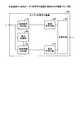
図35は、従来の符号化装置の一例を示す図である。図35に示すように、従来の符号化装置10は、低域信号抽出部11、低域符号化部12、高域情報抽出部13、高域符号化部14、多重化部15を有する。 FIG. 35 is a diagram showing an example of a conventional coding device. As shown in FIG. 35, the
低域信号抽出部11は、外部装置から音信号を取得し、音信号の低域信号を抽出する処理部である。低域信号抽出部11は、低域信号を、低域符号化部12に出力する。 The low-frequency signal extraction unit 11 is a processing unit that acquires a sound signal from an external device and extracts the low-frequency signal of the sound signal. The low frequency signal extraction unit 11 outputs the low frequency signal to the low
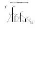
図36は、音信号の周波数スペクトルを示す図である。図36の横軸は、周波数に対応する軸であり、縦軸は、音信号の電力(値)に対応する軸である。たとえば、所定の周波数未満の周波数帯域を「低域」とし、所定の周波数以上の周波数帯域を「高域」とする。低域の音信号を「低域信号」とし、高域の音信号を「高域信号」とする。図36に示す例では、帯域5aが低域となり、帯域5bが高域となる。 FIG. 36 is a diagram showing a frequency spectrum of a sound signal. The horizontal axis of FIG. 36 is the axis corresponding to the frequency, and the vertical axis is the axis corresponding to the electric power (value) of the sound signal. For example, a frequency band below a predetermined frequency is defined as a "low frequency band", and a frequency band above a predetermined frequency is defined as a "high frequency band". The low-frequency sound signal is referred to as a "low-frequency signal", and the high-frequency sound signal is referred to as a "high-frequency signal". In the example shown in FIG. 36, the
低域符号化部12は、低域信号を符号化することで、「低域符号」を生成する処理部である。たとえば、低域符号化部12は、AAC(Advanced Audio Coding)に基づいて、符号化を行う。低域符号化部12は、低域符号を、多重化部15に出力する。 The low-
高域情報抽出部13は、外部装置から音信号を取得し、音信号に基づいて高域情報を抽出する処理部である。高域情報抽出部13は、高域情報を高域符号化部14に出力する。 The high-frequency information extraction unit 13 is a processing unit that acquires a sound signal from an external device and extracts high-frequency information based on the sound signal. The high-frequency information extraction unit 13 outputs high-frequency information to the high-
高域情報には、包絡電力、トーン周波数、周波数分解能が含まれる。包絡電力は、音信号の周波数スペクトルの高域について、包絡線を示すものであり、たとえば、図36の包絡電力6aに対応する。 High frequency information includes envelope power, tone frequency, and frequency resolution. The envelope power indicates an envelope in the high frequency range of the frequency spectrum of the sound signal, and corresponds to, for example, the
トーン周波数は、トーンの存在する周波数を示す。たとえば、トーンは、電力の値が突出して大きい電力である。図36に示す例では、トーン6bに示すものとなり、トーン周波数は、線分7に対応する周波数となる。周波数分解能は、周波数の分解能(最小単位)を示すものである。 The tone frequency indicates the frequency at which the tone is present. For example, a tone is a power with an outstandingly large power value. In the example shown in FIG. 36, the
高域符号化部14は、高域情報を符号化することで、「高域符号」を生成する処理部である。高域符号化部14は、高域符号を、多重化部15に出力する。 The high-
多重化部15は、低域符号と、高域符号とを多重化することで、ストリームを生成する処理部である。多重化部15は、ストリームを、ネットワークを介して、復号装置に送信する。 The multiplexing unit 15 is a processing unit that generates a stream by multiplexing the low frequency code and the high frequency code. The multiplexing unit 15 transmits the stream to the decoding device via the network.
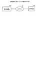
図37は、従来の復号装置の一例を示す図である。図37に示すように、従来の復号装置20は、分離部21、低域復号部22、高域生成部23、高域復号部24、高域整形部25を有する。 FIG. 37 is a diagram showing an example of a conventional decoding device. As shown in FIG. 37, the
分離部31は、符号化装置10からストリームを取得し、取得したストリームを、低域符号と高域符号とに分離する処理部である。分離部21は、低域符号を、低域復号部22に出力する。分離部21は、高域符号を、高域復号部24に出力する。 The separation unit 31 is a processing unit that acquires a stream from the
低域復号部22は、低域符号を復号することで、低域信号を抽出する処理部である。低域復号部22は、低域信号を、高域生成部23に出力する。 The low-
高域生成部23は、低域信号の波形を、高域側に複製することで、高域信号を生成する処理部である。高域生成部23は、低域信号と高域信号とを合わせた信号情報を、高域整形部25に出力する。 The high
高域復号部24は、高域符号を復号することで、高域情報を抽出する処理部である。高域復号部24は、高域情報を、高域整形部25に出力する。上記のように、高域情報には、包絡電力、トーン周波数、周波数分解能が含まれる。 The high-
高域整形部25は、高域情報を基にして、信号情報の高域信号を整形する処理部である。高域整形部25は、整形した信号情報を、外部装置に出力する。 The high-
図38は、従来の復号装置の処理を説明するための図である。図38のステップS10〜S11に示す周波数スペクトルの横軸は周波数に対応する軸であり、縦軸は電力(値)に対応する軸である。図38のステップS10について説明する。復号装置20の高域生成部23は、低域信号8aの波形を、高域側に複製することで、高域信号8bを生成する。 FIG. 38 is a diagram for explaining the processing of the conventional decoding device. The horizontal axis of the frequency spectrum shown in steps S10 to S11 of FIG. 38 is the axis corresponding to the frequency, and the vertical axis is the axis corresponding to the electric power (value). Step S10 of FIG. 38 will be described. The high
図38のステップS11について説明する。復号装置20の高域整形部25は、粗い分解能で、包絡電力に合わせて、高域信号8bを整形することで、信号8cを生成する。 Step S11 of FIG. 38 will be described. The high-
図38のステップS12について説明する。復号装置20の高域整形部25は、信号8cに、トーン周波数に対応する周波数位置にトーン8dを付加することで、信号情報8eを生成する。この信号情報8eが復号した音信号となる。 Step S12 of FIG. 38 will be described. The high
しかしながら、上述した従来技術では、音信号の音質が劣化するという問題がある。 However, the above-mentioned conventional technique has a problem that the sound quality of the sound signal is deteriorated.
たとえば、トーンが低域と高域との境界にある場合、高域側の分解能が粗いことにより、復号時に、低域とずれた周波数にトーンが生成されることがある。低域とずれた周波数にトーンが生成されると、隣接した2つのトーンが生成され、うなりが発生し、音質が劣化する。 For example, when the tone is at the boundary between the low frequency band and the high frequency band, the tone may be generated at a frequency deviated from the low frequency band at the time of decoding due to the coarse resolution on the high frequency band side. When a tone is generated at a frequency deviated from the low frequency range, two adjacent tones are generated, a beat occurs, and the sound quality deteriorates.
図39は、従来技術の問題を説明するための図である。たとえば、入力音の時間波形および周波数スペクトルを、時間波形30a、周波数スペクトル31aとする。復号音の時間波形および周波数スペクトルを時間波形30b、周波数スペクトル31bとする。時間波形30a,30bの横軸は時間に対応する軸であり、縦軸は、電力(値)に対応する軸である。周波数スペクトル31a,31bの横軸は周波数に対応する軸であり、縦軸は電力(値)に対応する軸である。 FIG. 39 is a diagram for explaining a problem of the prior art. For example, the time waveform and frequency spectrum of the input sound are the time waveform 30a and the
たとえば、入力音自体にはうなりは発生していないが、低域と高域の境界に1つのトーンが存在している。ここで、図38で説明したように、復号装置20が信号情報を生成すると、信号情報には、2つのトーン32a,32bが含まれてしまい、うなりの原因となる。 For example, the input sound itself does not growl, but there is one tone at the boundary between the low and high frequencies. Here, as described with reference to FIG. 38, when the
図40は、高域のトーンがずれる理由を説明するための図である。ステップS21について説明する。たとえば、低域信号には、ある電力値35aと、トーン36aが存在し、トーン36aが存在する周波数を境界とする。復号装置20の高域生成部23は、低域信号を高域側に複製することで、高域信号を生成する。たとえば、高域信号には、電力値35aに基づき複製された電力値35bと、トーン36aに基づき複製された電力値(トーン)36bが含まれる。 FIG. 40 is a diagram for explaining the reason why the high frequency tone shifts. Step S21 will be described. For example, in the low frequency signal, a
ステップS22について説明する。復号装置20の高域整形部25は、高域信号を包絡情報9に基づいて整形する。たとえば、分解能が粗いと、包絡情報9は、トーン36aの影響により、境界の値が大きくなり、右端側の値が小さくなるように調整されている。このため、電力値35bが、トーン36aと同等の大きさとなる電力値35b’に整形され、トーン36bが、電力値36b’に整形される。このうち、トーン36aと、電力値35b’とがうなり成分となり、音質が劣化する。 Step S22 will be described. The high-
1つの側面では、本発明は、音信号の音質が劣化することを抑止することができるオーディオ符号化装置、オーディオ符号化方法およびオーディオ符号化プログラムを提供することを目的とする。 In one aspect, it is an object of the present invention to provide an audio coding device, an audio coding method, and an audio coding program capable of suppressing deterioration of the sound quality of a sound signal.
第1の案では、オーディオ符号化装置は、判定部と、符号化部と、多重化部とを有する。判定部は、入力信号の低域と高域との境界にトーンが含まれるか否かを判定する。符号化部は、境界にトーンが含まれている場合に、低域、又は、高域の一方のトーンを抑圧し、入力信号の低域を符号化することで、低域符号を生成し、入力信号の高域を符号化することで、高域符号を生成する。多重化部は、低域符号と高域符号を多重化することで、符号化ストリームを生成する。 In the first plan, the audio coding device has a determination unit, a coding unit, and a multiplexing unit. The determination unit determines whether or not a tone is included in the boundary between the low frequency band and the high frequency band of the input signal. When a tone is included in the boundary, the coding unit suppresses one of the low-frequency or high-frequency tones and encodes the low-frequency of the input signal to generate a low-frequency code. A high frequency code is generated by encoding the high frequency band of the input signal. The multiplexing unit generates a coded stream by multiplexing the low-frequency code and the high-frequency code.
音信号の音質が劣化することを抑止することができる。 It is possible to prevent the sound quality of the sound signal from deteriorating.
以下に、本願の開示するオーディオ符号化装置、オーディオ符号化方法およびオーディオ符号化プログラムの実施例を図面に基づいて詳細に説明する。なお、この実施例によりこの発明が限定されるものではない。 Hereinafter, examples of the audio coding apparatus, the audio coding method, and the audio coding program disclosed in the present application will be described in detail with reference to the drawings. The present invention is not limited to this embodiment.
図1は、本実施例1に係るシステムの構成を示す図である。図1に示すように、このシステムは、オーディオ符号化装置100と、復号装置20とを有する。オーディオ符号化装置100は、ネットワーク50を介して、復号装置20に接続される。 FIG. 1 is a diagram showing a configuration of a system according to the first embodiment. As shown in FIG. 1, this system has an
オーディオ符号化装置100は、外部装置から音信号を取得し、音信号を符号化する装置である。たとえば、オーディオ符号化装置100は、トーンが低域・高域の境界にあることを検出した場合に、低域側のトーンまたは高域側のトーンの一方を抑圧した後、低域符号および高域符号を多重化してストリームを生成する。オーディオ符号化装置100は、ストリームを復号装置20に送信する。ストリームは、符号化ストリームに対応する。 The
復号装置20は、オーディオ符号化装置100からストリームを受信し、ストリームを復号する装置である。復号装置20の説明は、図37で説明した復号装置20の説明と同様である。 The
図2は、本実施例1に係るオーディオ符号化装置の構成を示す機能ブロック図である。図2に示すように、このオーディオ符号化装置100は、低域信号抽出部110、高域情報抽出部120、判定部130、低域補正部140、低域符号化部150、高域補正部160、高域符号化部170、多重化部180を有する。たとえば、低域信号抽出部110、高域情報抽出部120、低域補正部140、低域符号化部150、高域補正部160、高域符号化部170は、符号化部に対応する。 FIG. 2 is a functional block diagram showing a configuration of an audio coding device according to the first embodiment. As shown in FIG. 2, the
低域信号抽出部110は、外部装置から音信号を取得し、音信号の低域に含まれる低域信号を抽出する処理部である。低域信号抽出部110は、低域信号を、低域補正部140に出力する。管理者は、低域の上限周波数を予め設定しておくものとする。 The low frequency
高域情報抽出部120は、外部装置から音信号を取得し、音信号の高域から、高域情報を抽出する処理部である。高域情報抽出部120は、高域情報を、高域補正部160に出力する。高域情報には、包絡電力、トーン周波数、周波数分解能が含まれる。管理者は、高域の下限周波数を予め設定しておくものとする。また、高域の下限周波数は、低域の上限周波数より低い帯域でも良い。 The high-frequency
たとえば、高域情報抽出部120は、音信号を周波数スペクトルに変換し、周波数スペクトルの高域側の包絡線の形状を包絡電力として抽出する。高域情報抽出部120は、周波数スペクトルの高域について、電力が閾値以上となる周波数を、トーン周波数として抽出する。周波数分解能は、予め設定されているものとする。 For example, the high frequency
判定部130は、外部装置から音信号を取得し、音信号の低域と高域との境界にトーンが含まれるか否かを判定する処理部である。また、判定部130は、境界にトーンが含まれると判定した場合に、低域のトーンを抑圧するのか、高域のトーンを抑圧するのかを判定する。低域と高域との境界は、低域の上限から高域の下限の間の帯域とする。また、低域の上限から高域の下限の間の帯域の上下に幅を持たせても良い。例えば、「境界の帯の下限−ε〜境界の帯域の上限+ε」としても良い。 The
図3は、本実施例1に係る判定部の構成を示す機能ブロック図である。図3に示すように、この判定部130は、BPF(Band Pass Filter)131と、トーン検出部132と、補正判定部133とを有する。 FIG. 3 is a functional block diagram showing the configuration of the determination unit according to the first embodiment. As shown in FIG. 3, the
BPF131は、音信号のうち、低域と高域との境界付近の音信号を通過させるフィルタである。BPF131を通過した音信号は、トーン検出部132に出力される。 The
図4は、BPFを説明するための図である。図4において、横軸は周波数に対応する軸であり、縦軸は電力に対応する軸である。低域と高域との境界60を含むように、幅60aのBPFを適用する。幅60aは、低域の上限と、高域の下限を基にして、決定されても良い。たとえば、幅60aを「低域の上限−α〜高域の下限+α」としても良い。また、高域の下限周波数≦低域の下限周波数の場合は、幅60aを「高域の下限−α〜低域の上限+α」としても良い。 FIG. 4 is a diagram for explaining BPF. In FIG. 4, the horizontal axis is the axis corresponding to the frequency, and the vertical axis is the axis corresponding to the electric power. A BPF with a width of 60a is applied so as to include the
ここでは一例として、音信号から、境界付近の音信号を抽出する場合に、BPF131を用いたが、これに限定されるものではない。たとえば、FFT(Fast Fourier Transform)、MDCT(Modified Discrete Cosine Transform)、QMF(Quadrature Mirror Filter)変換等を用いて、境界付近の音信号を抽出しても良い。 Here, as an example, BPF131 is used when extracting a sound signal near the boundary from the sound signal, but the present invention is not limited to this. For example, a sound signal near the boundary may be extracted by using FFT (Fast Fourier Transform), MDCT (Modified Discrete Cosine Transform), QMF (Quadrature Mirror Filter) transform, or the like.
トーン検出部132は、境界付近の音信号にトーンが含まれているか否かを判定する処理部である。たとえば、トーン検出部132は、境界付近の音信号を基にして、トーン性を示す数値を算出し、トーン性を示す数値が閾値以上である場合に、トーンが含まれていると判定する。トーン検出部132に関する以下の説明では、境界付近の音信号を、単に音信号と表記する。トーン検出部132は、第1のトーン検出処理または第2のトーン検出処理を実行することで、トーンの有無を検出する。 The tone detection unit 132 is a processing unit that determines whether or not the sound signal near the boundary contains a tone. For example, the tone detection unit 132 calculates a numerical value indicating the tone property based on the sound signal near the boundary, and determines that the tone is included when the numerical value indicating the tone property is equal to or higher than the threshold value. In the following description of the tone detection unit 132, the sound signal near the boundary is simply referred to as a sound signal. The tone detection unit 132 detects the presence or absence of a tone by executing the first tone detection process or the second tone detection process.
第1のトーン検出処理の一例について説明する。トーン検出部132は、式(1)に基づいて、音信号のパワースペクトルの平坦性の逆数を、トーン性を示す数値T1として算出する。数値T1が小さいほど、音信号の周波数スペクトルの波形がより平坦であり、トーンが含まれている可能性が低いと言える。式(1)において、X(ω)は、周波数ωに対応する音信号の電力を示す。 An example of the first tone detection process will be described. Based on the equation (1), the tone detection unit 132 calculates the reciprocal of the flatness of the power spectrum of the sound signal as the numerical value T1 indicating the tone property. It can be said that the smaller the numerical value T1, the flatter the waveform of the frequency spectrum of the sound signal, and the less likely it is that the tone is included. In equation (1), X (ω) indicates the power of the sound signal corresponding to the frequency ω.

トーン検出部132は、数値T1が閾値TH1よりも大きい場合に、音信号にトーンが含まれていると判定する。一方、トーン検出部132は、数値T1が閾値TH1よりも大きくない場合に、音信号にトーンが含まれていないと判定する。 When the numerical value T1 is larger than the threshold value TH1, the tone detection unit 132 determines that the sound signal contains a tone. On the other hand, the tone detection unit 132 determines that the sound signal does not include a tone when the numerical value T1 is not larger than the threshold value TH1.
第2のトーン検出処理の一例について説明する。トーン検出部132は、式(2)、(3a)に基づいて、音信号の時間領域に関して、時刻iにおける音信号の値x(i)での自己相関R(j)を求め、自己相関R(j)の最大値を、トーン性を示す数値T2として算出する。トーン検出部132は、数値T2が閾値TH2よりも大きい場合に、音信号にトーンが含まれていると判定する。一方、トーン検出部132は、数値T2が閾値TH2よりも大きくない場合に、音信号にトーンが含まれていないと判定する。 An example of the second tone detection process will be described. Based on the equations (2) and (3a), the tone detection unit 132 obtains the autocorrelation R (j) at the sound signal value x (i) at time i with respect to the time domain of the sound signal, and the autocorrelation R The maximum value of (j) is calculated as the numerical value T2 indicating the tone property. When the numerical value T2 is larger than the threshold value TH2, the tone detection unit 132 determines that the sound signal contains a tone. On the other hand, the tone detection unit 132 determines that the sound signal does not include a tone when the numerical value T2 is not larger than the threshold value TH2.
T2=max(R(j))・・・(3a) T2 = max (R (j)) ... (3a)
トーン検出部132は、第1のトーン検出処理または第2のトーン検出処理を実行し、トーン有りと判定した場合には、トーン有の情報を、補正判定部133に出力する。また、トーン検出部132は、トーン電力を、低域補正部140および高域補正部160に出力する。トーン電力は、低域と高域との境界に存在するトーンの電力である。 The tone detection unit 132 executes the first tone detection process or the second tone detection process, and when it is determined that there is a tone, the tone detection unit 132 outputs the information with the tone to the correction determination unit 133. Further, the tone detection unit 132 outputs the tone power to the low
一方、トーン検出部132は、トーン無と判定した場合には、トーン無の情報を、補正判定部133に出力する。 On the other hand, when the tone detection unit 132 determines that there is no tone, the tone detection unit 132 outputs the information of no tone to the correction determination unit 133.
補正判定部133は、トーン検出部132から「トーン有」である旨の情報を取得した場合には、符号化条件を取得し、符号化条件を基にして、音信号の低域のトーンを抑圧するのか、高域のトーンを抑圧するのかを判定する処理部である。符号化条件は、たとえば、符号化のビットレートの情報を含む。符号化条件の情報は、管理者が入力しても良いし、補正判定部133に予め設定しておいても良い。 When the correction determination unit 133 acquires the information indicating that "there is a tone" from the tone detection unit 132, the correction determination unit 133 acquires the coding condition, and based on the coding condition, determines the low-frequency tone of the sound signal. It is a processing unit that determines whether to suppress or suppress high-frequency tones. The coding condition includes, for example, information on the bit rate of coding. The information of the coding condition may be input by the administrator, or may be set in advance in the correction determination unit 133.
補正判定部133は、符号化条件に含まれるビットレートの値が、閾値以上である場合に、符号化条件が高レートであると判定する。補正判定部133は、高レートであると判定した場合に、高域のトーンを抑圧すると判定し、制御信号を、高域補正部160に出力する。 The correction determination unit 133 determines that the coding condition is a high rate when the value of the bit rate included in the coding condition is equal to or greater than the threshold value. When the correction determination unit 133 determines that the rate is high, it determines that the high frequency tone is suppressed, and outputs a control signal to the high
補正判定部133は、符号化条件に含まれるビットレートの値が、閾値未満である場合に、符号化条件が低レートであると判定する。補正判定部133は、低レートであると判定した場合に、低域のトーンを抑圧すると判定し、制御信号を、低域補正部140に出力する。 The correction determination unit 133 determines that the coding condition is a low rate when the value of the bit rate included in the coding condition is less than the threshold value. When the correction determination unit 133 determines that the rate is low, it determines that the low frequency tone is suppressed, and outputs a control signal to the low
図2の説明に戻る。低域補正部140は、判定部130から制御信号を受け付けた場合に、低域信号に含まれる境界のトーン成分を抑圧することで、低域信号を補正する処理部である。低域補正部140は、補正した低域信号を、低域符号化部150に出力する。 Returning to the description of FIG. The low-
低域補正部140は、判定部130から制御信号を受け付けていない場合には、低域信号抽出部110から受け付ける低域信号を、そのまま、低域符号化部150に出力する。 When the low-
図5は、本実施例1に係る低域補正部の構成を示す機能ブロック図である。図5に示すように、この低域補正部140は、スイッチ141と、抑圧ゲイン算出部142と、平滑化部143と、トーン抑圧部144とを有する。 FIG. 5 is a functional block diagram showing a configuration of a low frequency correction unit according to the first embodiment. As shown in FIG. 5, the low
スイッチ141は、判定部130から取得する制御信号に応じて、低域信号の経路を切り替えるスイッチである。スイッチ141は、制御信号を受け付けていない場合には、端子141aと端子141bとを接続することで、低域信号をそのまま通過させる。スイッチ141は、制御信号を受け付けた場合には、端子141aと端子141cとを接続することで、低域信号を、トーン抑圧部144に入力する。 The
抑圧ゲイン算出部142は、低域信号のトーンを動的マスキング閾値以下に抑圧するゲインを算出する処理部である。動的マスキング閾値は、抑圧対象のトーンが存在する周波数と、トーン電力との組に応じて決定される閾値である。 The suppression
図6は、動的マスキング閾値を説明するための図である。図6において、横軸は周波数に対応する軸であり、縦軸は電力に対応する軸である。たとえば、トーンが隣接する場合であっても、トーン電力が動的マスキング閾値未満である場合には、トーンが聞こえなくなる。 FIG. 6 is a diagram for explaining the dynamic masking threshold value. In FIG. 6, the horizontal axis is the axis corresponding to the frequency, and the vertical axis is the axis corresponding to the electric power. For example, even if the tones are adjacent, if the tone power is less than the dynamic masking threshold, the tones are inaudible.
トーン65Aの動的マスキング閾値は、閾値66となる。トーン65Aのトーン電力は閾値66以上であるため、トーン65Aの音は聞こえる。一方、トーン65Aのトーン電力を抑圧して、トーン65Bに補正すると、閾値66未満となり、トーン65Bの音は聞こえない。 The dynamic masking threshold of the
トーン65Cの動的マスキング閾値は、閾値67となる。トーン65Cのトーン電力は閾値67以上であるため、トーン65Cの音は聞こえる。一方、トーン65Cのトーン電力を抑圧して、トーン65Dに補正すると、閾値67未満となり、トーン65Dの音は聞こえない。 The dynamic masking threshold of the
抑圧ゲイン算出部142は、トーンの周波数およびトーン電力と、動的マスキング閾値とを対応づけたテーブルを参照して、動的マスキング閾値を特定する。たとえば、トーンの周波数を、低域と高域との境界の周波数とする。抑圧ゲイン算出部142は、トーン電力と、動的マスキング閾値とを比較して、トーン電力が動的マスキング閾値未満となる抑圧ゲインを特定する。抑圧ゲイン算出部142は、抑圧ゲインを平滑化部143に出力する。 The suppression
平滑化部143は、低域信号のトーン成分をなだらかに抑圧するために、段階的に大きくする抑圧ゲインを、トーン抑圧部144に出力する処理部である。たとえば、平滑化部143は、抑圧ゲインを初期値から徐々に大きくしていき、最終的に、抑圧ゲインの大きさを、抑圧ゲイン算出部142から通知される抑圧ゲインの大きさになるように調整する。 The smoothing
トーン抑圧部144は、平滑化部143から取得する抑圧ゲインを、トーン成分に乗算することで、境界のトーンを抑圧し、低域信号を補正する処理部である。トーン抑圧部144は、補正した低域信号を、低域符号化部150に出力する。 The
図7は、本実施例1に係る低域補正部の処理を説明するための図である。図7において、補正前の低域信号の周波数スペクトルを、周波数スペクトル70aとする。補正後の低域信号の周波数スペクトルを、周波数スペクトル70bとする。周波数スペクトル70a,70bの横軸は、周波数に対応する軸であり、周波数スペクトル70a,70bの縦軸は、電力に対応する軸である。 FIG. 7 is a diagram for explaining the processing of the low frequency correction unit according to the first embodiment. In FIG. 7, the frequency spectrum of the low frequency signal before correction is defined as the
周波数スペクトル70aに示すように、境界にトーン71aがある。トーン71aに対応する動的マスキング閾値を、動的マスキング閾値72とする。トーン抑圧部144は、トーン71aが動的マスキング閾値72未満となるような抑圧ゲインを与えることで、トーン71aを、トーン71bに補正する。これにより、トーン71bが、動的マスキング閾値72未満となり、聞こえなくなるため、音信号の音質が劣化することができる。 As shown in the
図2の説明に戻る。低域符号化部150は、低域補正部から低域信号を取得し、低域信号をビット列に符号化することで、低域符号を生成する処理部である。たとえば、低域符号化部150は、AACに基づいて、符号化を行う。低域符号化部150は、低域符号を、多重化部180に出力する。 Returning to the description of FIG. The low-
高域補正部160は、判定部130から制御信号を受け付けた場合に、高域情報に含まれる境界の包絡電力を抑圧することで、高域情報を補正する処理部である。高域補正部160は、補正した高域情報を、高域符号化部170に出力する。 The high
高域補正部160は、判定部130から制御信号を受け付けていない場合には、高域情報抽出部120から取得する高域情報を、そのまま、高域符号化部170に出力する。 When the high-
図8は、本実施例1に係る高域補正部の構成を示す機能ブロック図である。図8に示すように、この高域補正部160は、スイッチ161と、抑圧ゲイン算出部162と、平滑化部163と、トーン抑圧部164とを有する。 FIG. 8 is a functional block diagram showing a configuration of a high frequency correction unit according to the first embodiment. As shown in FIG. 8, the high
スイッチ161は、判定部130から取得する制御信号に応じて、高域情報の経路を切り替えるスイッチである。スイッチ161は、制御信号を受け付けていない場合には、端子161aと端子161bとを接続することで、高域情報をそのまま通過させる。スイッチ161は、制御信号を受け付けた場合には、端子161aと端子161cとを接続することで、高域情報を、トーン抑圧部164に入力する。 The
抑圧ゲイン算出部162は、高域情報に含まれる境界の包絡電力(トーン電力)を動的マスキング閾値以下に抑圧するゲインを算出する処理部である。動的マスキング閾値は、境界の周波数と、境界の包絡電力との組に応じて決定される閾値である。 The suppression
抑圧ゲイン算出部162は、境界の周波数および境界の包絡電力と、動的マスキング閾値とを対応づけたテーブルを参照して、動的マスキング閾値を特定する。抑圧ゲイン算出部162は、境界の包絡電力と、動的マスキング閾値とを比較して、包絡電力が動的マスキング閾値未満となる抑圧ゲインを特定する。抑圧ゲイン算出部162は、抑圧ゲインを平滑化部163に出力する。 The suppression
平滑化部163は、包絡電力の値をなだらかに抑圧するために、段階的に大きくする抑圧ゲインを、トーン抑圧部164に出力する処理部である。たとえば、平滑化部163は、抑圧ゲインを初期値から徐々に大きくしていき、最終的に、抑圧ゲインの大きさを、抑圧ゲイン算出部162から通知される抑圧ゲインの大きさになるように調整する。 The smoothing
トーン抑圧部164は、平滑化部163から取得する抑圧ゲインを、境界の包絡電力に乗算することで、高域情報を補正する処理部である。境界の包絡電力を抑制することで、復号装置20で復号される境界のトーンが、動的マスキング閾値未満となる。トーン抑圧部164は、補正した高域情報を、高域符号化部170に出力する。なお、トーン抑圧部164は、高域情報に含まれる包絡電力、トーン周波数、周波数分解能のうち、包絡電力のみ補正し、トーン周波数、周波数分解能の補正は行わないものとする。 The
図9は、本実施例1に係る高域補正部の処理を説明するための図である。図9において、補正前の包絡電力76aを、周波数スペクトル75a上に示す。補正後の包絡電力76bを、周波数スペクトル75b上に示す。周波数スペクトル75a,75bの横軸は、周波数に対応する軸であり、周波数スペクトル75a,75bの縦軸は、電力に対応する軸である。また、低域と高域との境界を、境界77とする。 FIG. 9 is a diagram for explaining the processing of the high frequency correction unit according to the first embodiment. In FIG. 9, the
たとえば、境界77付近の包絡電力76aに対応する動的マスキング閾値を、動的マスキング閾値78とする。トーン抑圧部164は、境界77の包絡電力76aが、動的マスキング閾値78未満となるように、包絡電力76aを抑圧した包絡電力76bを生成することで、高域情報を補正する。包絡電力76bは、動的マスキング閾値78未満であるため、この包絡電力76bを基に復号される境界のトーン成分が抑えられる。 For example, the dynamic masking threshold value corresponding to the
図2の説明に戻る。多重化部180は、低域符号と、高域符号とを多重化することで、ストリームを生成する処理部である。多重化部180は、ストリームを、ネットワーク50を介して、復号装置20に送信する。 Returning to the description of FIG. The
次に、本実施例1に係るオーディオ符号化装置100の判定部130の処理手順について説明する。図10は、本実施例1に係る判定部の処理手順を示すフローチャート(1)である。図10に示すように、オーディオ符号化装置100の判定部130は、トーン性Tを算出する(ステップS101)。ステップS101において、判定部130は、第1のトーン検出処理によりトーン性T1を算出しても良いし、第2のトーン検出処理によりトーン性T2を算出しても良い。 Next, the processing procedure of the
判定部130は、トーン性Tが、閾値THよりも大きいか否かを判定する(ステップS102)。ステップS102において、判定部130は、トーン性T1を算出した場合には、閾値TH1と比較する。判定部130は、トーン性T2を算出した場合には、閾値TH2と比較する。 The
判定部130は、トーン性Tが閾値THよりも大きい場合には(ステップS102,Yes)、トーン有と判定する(ステップS104)。一方、判定部130は、トーン性Tが閾値THよりも大きくない場合には(ステップS102,No)、トーン無と判定する(ステップS103)。判定部130は、トーン電力を計算する(ステップS105)。 When the tone property T is larger than the threshold value TH (step S102, Yes), the
図11は、本実施例1に係る判定部の処理手順を示すフローチャート(2)である。図11に示すように、オーディオ符号化装置100の判定部130は、トーン検出結果が、トーン有りであるか否かを判定する(ステップS201)。判定部130は、トーン検出結果が、トーン有りでない場合には(ステップS201,No)、補正処理を実行しない旨の制御信号を出力する(ステップS202)。なお、ステップS202において、判定部130は、補正処理を実行しないと判定した場合に、制御信号の出力を抑止しても良い。 FIG. 11 is a flowchart (2) showing a processing procedure of the determination unit according to the first embodiment. As shown in FIG. 11, the
判定部130は、トーン検出結果が、トーン有りの場合には(ステップS201,Yes)、符号化条件のビットレートが所定値以上であるか否かを判定する(ステップS203)。判定部130は、符号化条件のビットレートが所定値以上である場合には(ステップS203,Yes)、高域補正を行う旨の、制御信号を高域補正部160に出力する(ステップS204)。 When the tone detection result has a tone (step S201, Yes), the
判定部130は、符号化条件のビットレートが所定値以上でない場合には(ステップS203,No)、低域補正を行う旨の、制御信号を低域補正部140に出力する(ステップS205)。 When the bit rate of the coding condition is not equal to or higher than a predetermined value (step S203, No), the
次に、本実施例1に係るオーディオ符号化装置100の処理手順の一例について説明する。図12は、本実施例1に係るオーディオ符号化装置の処理手順を示すフローチャートである。図12に示すように、このオーディオ符号化装置100は、音信号を受け付ける(ステップS301)。 Next, an example of the processing procedure of the
オーディオ符号化装置100の低域信号抽出部110は、音信号から低域信号を抽出する(ステップS302)。オーディオ符号化装置100の高域情報抽出部120は、音信号から高域情報を抽出する(ステップS303)。 The low-frequency
オーディオ符号化装置100の判定部130は、境界におけるトーンの有無を判定する。判定部130は、トーン有の場合には、低域を補正するのか、高域を補正するのかを判定する(ステップS304)。 The
オーディオ符号化装置100の低域補正部140は、低域を補正すると判定された場合に、低域信号を補正する(ステップS305)。オーディオ符号化装置100の高域補正部160は、高域を補正すると判定された場合に、高域情報の包絡電力を補正する(ステップS306)。 The low-
オーディオ符号化装置100の低域符号化部150は、低域信号を符号化して、低域符号を生成する(ステップS307)。オーディオ符号化装置100の高域符号化部170は、高域情報を符号化して、高域符号を生成する(ステップS308)。 The low-
オーディオ符号化装置100の多重化部180は、低域符号と高域符号とを多重化したストリームを生成する(ステップS309)。多重化部180は、ストリームを復号装置20に送信する(ステップS310)。 The
次に、本実施例1に係るオーディオ符号化装置100の効果について説明する。オーディオ符号化装置100は、トーンが低域・高域の境界にあることを検出した場合に、低域側または高域側のトーンの一方を抑圧した後に、低域符号および高域符号を多重化したストリームを生成する。これにより、音信号の音質が劣化することを抑止することができる。 Next, the effect of the
たとえば、オーディオ符号化装置100は、トーンが境界にあることを検出し、低域信号のトーンを抑圧することで、たとえば、図39のトーン32aが小さくなる。これにより、うなり成分がなくなり、音質劣化を抑止できる。オーディオ符号化装置100は、トーンが境界にあることを検出し、高域情報のトーン(包絡電力)を抑圧することで、たとえば、図39のトーン32bが小さくなる。これにより、うなり成分がなくなり、音質劣化を抑止できる。 For example, the
オーディオ符号化装置100は、符号化条件のビットレートと閾値との比較により、低域のトーンを抑圧するのか、高域のトーンを抑圧するのかを判定し、判定結果に応じた帯域のトーンを抑圧する。これにより、ビットレートに応じて、音質の劣る方の帯域で、補正を行うことができる。たとえば、ビットレートが高レートの場合には、高域の音質が劣るため、高域を補正する。一方、ビットレートが低レートの場合には、低域の音質が劣るため、低域を補正する。 The
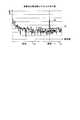
図13は、本実施例1に係るオーディオ符号化装置の効果を説明するための図である。図13において、スペクトラム81a、時間波形82aは、原音(正解)のスペクトラムおよび時間波形である。一例として、チェンバロの響きが衰退するトーン(16bit、48kHz、mono)を原音として用いた。また、低域と高域との境界を6.7kHzとした。 FIG. 13 is a diagram for explaining the effect of the audio coding device according to the first embodiment. In FIG. 13, the spectrum 81a and the time waveform 82a are the spectrum and the time waveform of the original sound (correct answer). As an example, a tone (16 bit, 48 kHz, mono) in which the harpsichord reverberates is used as the original sound. The boundary between the low range and the high range was set to 6.7 kHz.
スペクトラム81b、時間波形82bは、従来の符号化装置10が符号化したストリームを復号装置20が復号した信号に関する、スペクトラムおよび時間波形である。スペクトラム81c、時間波形82cは、オーディオ符号化装置100が符号化したストリームを復号装置20が復号した信号に関する、スペクトラムおよび時間波形である。 The spectrum 81b and the
スペクトラム81a〜81cの横軸は時間に対応する軸であり、縦軸は周波数に対応する軸である。また、スペクトラム81a〜81cでは、明暗により電力値の大小を表しており、明るい部分は、電力が大きく、暗い部分は、電力が小さい。時間波形82a〜82cの横軸は時間に対応する軸であり、縦軸は振幅に対応する軸である。 The horizontal axis of the spectra 81a to 81c is the axis corresponding to time, and the vertical axis is the axis corresponding to frequency. Further, in the spectra 81a to 81c, the magnitude of the electric power value is indicated by light and dark, and the bright portion has a large electric power and the dark portion has a small electric power. The horizontal axis of the time waveforms 82a to 82c is the axis corresponding to time, and the vertical axis is the axis corresponding to the amplitude.
スペクトラム81a〜81cを比較、および、時間波形82a〜82cを比較すると、従来技術と比較して、オーディオ符号化装置100の符号化は、ゆらぎが抑えられ、音質劣化を抑止できている。 Comparing the spectra 81a to 81c and comparing the time waveforms 82a to 82c, the coding of the
ところで、図2に示したオーディオ符号化装置100は、低域補正部140および高域補正部160のいずれか一方を有していれば良く、必ずしも、低域補正部140および高域補正部160の双方を有していなくても良い。 By the way, the
たとえば、オーディオ符号化装置100が、低域補正部140を有し、高域補正部160を有していない場合には、境界のトーンが検出される度に、低域補正部140が、低域信号の補正を行う。一方、オーディオ符号化装置100が、低域補正部140を有しておらず、高域補正部160を有している場合には、境界のトーンが検出される度に、高域補正部160が、高域情報の包絡電力の補正を行う。このように構成することで、オーディオ符号化装置100のハードウェア資源を節約しつつ、音信号の劣化を抑止することができる。 For example, when the
図14は、本実施例2に係るオーディオ符号化装置の構成を示す機能ブロック図である。図14に示すように、このオーディオ符号化装置200は、判定部210と、入力信号補正部220とを有する。オーディオ符号化装置200は、低域信号抽出部110、高域情報抽出部120、低域符号化部150、高域符号化部170、多重化部180を有する。 FIG. 14 is a functional block diagram showing the configuration of the audio coding device according to the second embodiment. As shown in FIG. 14, the
判定部210は、外部装置から音信号を取得し、音信号の低域と高域との境界にトーンが含まれるか否かを判定する処理部である。また、判定部210は、境界にトーンが含まれると判定した場合に、制御信号と、トーン電力を入力信号補正部220に出力する。判定部210が、境界にトーンが含まれるか否かを判定する処理は、実施例1に示した判定部130の処理と同様である。 The
入力信号補正部220は、判定部210から制御信号を受け付けた場合に、音信号に含まれる境界のトーン成分を抑圧することで、音信号を補正する処理部である。入力信号補正部220は、補正した音信号を、低域信号抽出部110に出力する。 The input
図15は、本実施例2に係る入力信号補正部の構成を示す機能ブロック図である。図15に示すように、この入力信号補正部220は、スイッチ221と、抑圧ゲイン算出部222と、平滑化部223と、トーン抑圧部224とを有する。 FIG. 15 is a functional block diagram showing a configuration of an input signal correction unit according to the second embodiment. As shown in FIG. 15, the input
スイッチ221は、判定部210から取得する制御信号に応じて、音信号の経路を切り替えるスイッチである。スイッチ221は、制御信号を受け付けていない場合には、端子221aと端子221bとを接続することで、音信号をそのまま通過させる。スイッチ221は、制御信号を受け付けた場合には、端子221aと端子221cとを接続することで、音信号を、トーン抑圧部224に入力する。 The
抑圧ゲイン算出部222は、音信号の境界に位置するトーンを動的マスキング閾値以下に抑圧するゲインを算出する処理部である。抑圧ゲイン算出部222は、抑圧ゲインを平滑化部223に出力する。抑圧ゲイン算出部222が、抑圧ゲインを算出する処理は、実施例1に示した抑圧ゲイン算出部142の処理に対応する。 The suppression
平滑化部223は、音信号のトーン成分をなだらかに抑圧するために、段階的に大きくする抑圧ゲインを、トーン抑圧部224に出力する処理部である。たとえば、平滑化部223は、抑圧ゲインを初期値から徐々に大きくしていき、最終的に、抑圧ゲインの大きさを、抑圧ゲイン算出部222から通知される抑圧ゲインの大きさになるように調整する。 The smoothing
トーン抑圧部224は、平滑化部223から取得する抑圧ゲインを、音信号の境界のトーン成分に乗算することで、境界のトーンを抑圧し、低域信号を補正する処理部である。トーン抑圧部224は、補正した音信号を、低域信号抽出部110に出力する。 The
図14の説明に戻る。低域信号抽出部110、高域情報抽出部120、低域符号化部150、高域符号化部170、多重化部180に関する説明は、実施例1に示した、低域信号抽出部110、高域情報抽出部120、低域符号化部150、高域符号化部170、多重化部180に関する説明と同様であるため、同一の符号を付して説明を省略する。 Returning to the description of FIG. The description of the low-frequency
次に、本実施例2に係るオーディオ符号化装置200の効果について説明する。トーンが低域・高域の境界にあることを検出した場合に、音信号の境界のトーンを抑圧した後に、低域符号および高域符号を多重化したストリームを生成する。これにより、音信号の音質が劣化することを抑止することができる。また、原音となる音信号のトーンを抑圧しておくため、低域、高域のいずれのトーンを抑圧するのかを判定する処理をスキップすることができるため、処理負荷を軽減することができる。また、ハードウェア資源を節約することも可能になる。 Next, the effect of the
図16Aは、本実施例3に係るオーディオ符号化装置の構成を示す機能ブロック図である。図16Aに示すように、オーディオ符号化装置300は、低域信号抽出部110、高域情報抽出部120、高域符号化部170、多重化部180、補正制御部310、低域符号化部320を有する。 FIG. 16A is a functional block diagram showing the configuration of the audio coding device according to the third embodiment. As shown in FIG. 16A, the
低域信号抽出部110、高域情報抽出部120、高域符号化部170、多重化部180に関する説明は、実施例1に説明した低域信号抽出部110、高域情報抽出部120、高域符号化部170、多重化部180に関する説明と同様である。 The description of the low-frequency
補正制御部310は、低域信号を符号化する際の対象となる帯域を制限する処理部である。補正制御部310は、符号化部の一例である。実施例3に関して、以下の説明では、低域信号を符号化する際の対象となる帯域を、「符号化対象帯域」と表記する。 The
図16Bは、本実施例3に係る補正制御部の処理を説明するための図である。図16Bに示す周波数スペクトル85の横軸は、周波数に対応する軸であり、縦軸は、音信号の電力(値)に対応する軸である。たとえば、音信号の境界86には、トーン86aが存在している。 FIG. 16B is a diagram for explaining the processing of the correction control unit according to the third embodiment. The horizontal axis of the
たとえば、符号化対象帯域のデフォルトの帯域は、符号化対象帯域87aとなる。補正制御部310は、符号化対象帯域87aを、符号化対象帯域87bに補正する。たとえば、補正制御部310は、符号化対象帯域87bは、符号化対象帯域87aの上限を1サブバンド分低域にずらしたものに対応する。補正制御部310は、補正した符号化対象帯域の情報を、低域符号化部320に出力する。 For example, the default band of the coding target band is the
低域符号化部320は、低域信号抽出部110から低域信号を取得し、低域信号をビット列に符号化することで、低域符号を生成する処理部である。低域符号化部320は、低域符号を、多重化部180に出力する。なお、低域符号化部320は、補正制御部310から受け付ける、符号化対象帯域87bに含まれる低域信号を符号化する。符号化対象帯域87bには、境界86のトーン86aが含まれないので、このトーン86aが、低域符号に含まれないこととなり、結果として、音質劣化を抑止することが可能となる。 The low-
次に、本実施例3に係るオーディオ符号化装置300の効果について説明する。オーディオ符号化装置300は、低域信号を符号化する場合に、トーンの存在する境界を除いた、符号化対象帯域の音信号に対して符号化を行う。これにより、境界のトーンが、低域信号に含まれないため、音質劣化を抑止することが可能となる。 Next, the effect of the
図17Aは、本実施例4に係るオーディオ符号化装置の構成を示す機能ブロック図である。図17Aに示すように、オーディオ符号化装置301は、低域信号抽出部110、低域符号化部150、高域符号化部170、多重化部180、補正制御部302、高域情報抽出部303を有する。 FIG. 17A is a functional block diagram showing the configuration of the audio coding device according to the fourth embodiment. As shown in FIG. 17A, the audio coding device 301 includes a low frequency
低域信号抽出部110、低域符号化部150、高域符号化部170、多重化部180に関する説明は、実施例1に説明した低域信号抽出部110、低域符号化部150、高域符号化部170、多重化部180に関する説明と同様である。 The description of the low-frequency
補正制御部302は、高域信号を符号化する際の対象となる帯域を制限する処理部である。補正制御部302は、符号化部の一例である。実施例4に関して、以下の説明では、高域信号を符号化する際の対象となる帯域を、「符号化対象帯域」と表記する。 The
図17Bは、本実施例4に係る補正制御部の処理を説明するための図である。図17Bに示す周波数スペクトル85の横軸は、周波数に対応する軸であり、縦軸は、音信号の電力(値)に対応する軸である。たとえば、音信号の境界86には、トーン86aが存在している。 FIG. 17B is a diagram for explaining the processing of the correction control unit according to the fourth embodiment. The horizontal axis of the
たとえば、符号化対象帯域のデフォルトの帯域は、符号化対象帯域89aとなる。補正制御部302は、符号化対象帯域89aを、符号化対象帯域89bに補正する。たとえば、符号化対象帯域89bは、符号化対象帯域89aの下限を1サブバンド分高域にずらしたものに対応する。補正制御部302は、補正した符号化対象帯域の情報を、高域情報抽出部303に出力する。 For example, the default band of the coding target band is the
高域情報抽出部303は、外部装置から音信号を取得し、音信号の高域(図17Bに示した符号化対象帯域89b)から、高域情報を抽出する処理部である。高域情報抽出部303は、高域情報を、高域符号化部170に出力する。図17Bで説明したように、符号化対象帯域89bには、トーン86aが存在していない。 The high frequency
次に、本実施例4に係るオーディオ符号化装置301の効果について説明する。オーディオ符号化装置301は、高域信号を符号化する場合に、トーンの存在する境界を除いた、符号化対象帯域の音信号に対して符号化を行う。これにより、境界のトーンが、高域信号に含まれないため、音質劣化を抑止することが可能となる。 Next, the effect of the audio coding device 301 according to the fourth embodiment will be described. When encoding a high-frequency signal, the audio coding device 301 encodes the sound signal in the coding target band excluding the boundary where the tone exists. As a result, since the boundary tone is not included in the high frequency signal, it is possible to suppress the deterioration of sound quality.
図18は、本実施例5に係るオーディオ符号化装置の構成を示す機能ブロック図である。図18に示すように、このオーディオ符号化装置400の構成は、低域信号抽出部110、高域情報抽出部120、判定部130、低域補正部140、低域符号化部150、高域符号化部170、多重化部180、高域補正部410を有する。高域補正部410は、符号化部の一例である。 FIG. 18 is a functional block diagram showing the configuration of the audio coding device according to the fifth embodiment. As shown in FIG. 18, the configuration of the
低域信号抽出部110、高域情報抽出部120、判定部130、低域補正部140、低域符号化部150、高域符号化部170、多重化部180に関する説明は、図2に示した各処理部に関する説明と同様であるため、同様の符号を付して説明を省略する。 A description of the low-frequency
高域補正部410は、判定部130から制御信号を受け付けた場合に、高域情報に含まれるトーン周波数を補正することで、高域情報を補正する処理部である。たとえば、トーン周波数の情報には、分解能に応じて分割された高域の複数の帯域について、トーンの有無に関する情報が含まれている。高域補正部410は、境界に対応する帯域のトーンの有無が「有」となっている場合に、境界に対応する帯域のトーンの有無を「無」に補正する。 The high
図19は、本実施例5に係る高域補正部の構成を示す機能ブロック図である。図19に示すように、この高域補正部410は、スイッチ411と、追加トーン抑圧部412とを有する。 FIG. 19 is a functional block diagram showing a configuration of a high frequency correction unit according to the fifth embodiment. As shown in FIG. 19, the high
スイッチ411は、判定部130から取得する制御信号に応じて、高域情報の経路を切り替えるスイッチである。スイッチ411は、制御信号を受け付けていない場合には、端子411aと端子411bとを接続することで、高域情報をそのまま通過させる。スイッチ411は、制御信号を受け付けた場合には、端子411aと端子411cとを接続することで、高域情報を、追加トーン抑圧部412に入力する。 The
追加トーン抑圧部412は、高域情報に含まれるトーン周波数を補正する処理部である。図20は、本実施例5に係る高域補正部の処理を説明するための図である。図20において、周波数スペクトル90の横軸は、周波数に対応する軸であり、縦軸は、信号の電力に対応する軸である。図20に示す例では、境界91にトーン92が含まれている。 The additional
たとえば、トーン周波数は、該当する帯域にトーンがあるか否かを「0」または「1」で示す情報であり、分割される帯域の細かさは、周波数分解能に応じたものとなる。トーンがある場合には、該当する帯域のブロックに「1」が設定され、トーンがない場合には、該当する帯域のブロックに「0」が設定される。 For example, the tone frequency is information indicating whether or not there is a tone in the corresponding band by "0" or "1", and the fineness of the divided band depends on the frequency resolution. If there is a tone, "1" is set in the block of the corresponding band, and if there is no tone, "0" is set in the block of the corresponding band.
図20に示したトーン周波数95a,95bは、各帯域対応するブロック21〜25が含まれる。このうち、ブロック21が、境界91の帯域に対応するブロックとなる。トーン周波数95aは、補正前のトーン周波数であり、トーン周波数95bは、補正後のトーン周波数である。 The
追加トーン抑圧部412は、トーン周波数95aのブロック21に「1」が設定されている場合には、ブロック21を「0」に補正することで、トーン周波数95bを生成する。追加トーン抑圧部412は、補正したトーン周波数95bと、包絡電力と、周波数分解能とを含む高域情報を、高域符号化部170に出力する。 When the
次に、本実施例5に係るオーディオ符号化装置400の効果について説明する。オーディオ符号化装置400は、境界にトーンが存在する場合には、高域情報のトーン周波数を補正することで、境界にトーンが存在しないことにする。これにより、補正された高域情報に基づいて復号される高域信号の境界には、トーンが生成されなくなるため、音質劣化を抑止することが可能となる。 Next, the effect of the
ところで、実施例1〜5に示したオーディオ符号化装置100〜400の処理は一例である。ここでは、オーディオ符号化装置のその他の処理について説明を行う。ここでは、図2に示したオーディオ符号化装置100のブロック図を用いて説明を行う。 By the way, the processing of the
オーディオ符号化装置100の判定部130は、低域の誤差電力と、高域の誤差電力とを比較して、低域のトーンを抑圧するのか、高域のトーンを抑圧するのかを判定しても良い。 The
たとえば、音信号(原音)の低域信号を第1低域信号と表記し、低域符号を復号した低域信号を第2低域信号と表記する。低域の誤差電力を、第1低域信号と第2低域信号との差分値とする。音信号(原音)の高域信号を第1高域信号と表記し、高域符号に基づき復号した高域信号を第2高域信号と表記する。高域の誤差電力を、第1高域信号と第2高域信号との差分値とする。 For example, the low-frequency signal of the sound signal (original sound) is referred to as a first low-frequency signal, and the low-frequency signal obtained by decoding the low-frequency code is referred to as a second low-frequency signal. The low-frequency error power is defined as the difference value between the first low-frequency signal and the second low-frequency signal. The high-frequency signal of the sound signal (original sound) is referred to as a first high-frequency signal, and the high-frequency signal decoded based on the high-frequency code is referred to as a second high-frequency signal. The high frequency error power is defined as the difference value between the first high frequency signal and the second high frequency signal.
判定部130は、低域の誤差電力>高域の誤差電力となる場合には、高域のトーンを抑圧すると判定する。一方、判定部130は、低域の誤差電力≦高域の誤差電力となる場合には、低域のトーンを抑圧すると判定する。 The
図21は、判定部のその他の処理手順を示すフローチャートである。図21に示すように、オーディオ符号化装置100の判定部130は、トーン検出結果が、トーン有りであるか否かを判定する(ステップS401)。判定部130は、トーン検出結果が、トーン有りでない場合には(ステップS401,No)、補正処理を実行しない旨の制御信号を出力する(ステップS402)。なお、ステップS402において、判定部130は、補正処理を実行しないと判定した場合に、制御信号の出力を抑止しても良い。 FIG. 21 is a flowchart showing other processing procedures of the determination unit. As shown in FIG. 21, the
判定部130は、トーン検出結果が、トーン有りの場合には(ステップS401,Yes)、低域の誤差電力>高域の誤差電力となるか否かを判定する(ステップS403)。判定部130は、低域の誤差電力>高域の誤差電力となる場合には(ステップS403,Yes)、高域補正を行う旨の、制御信号を高域補正部160に出力する(ステップS404)。 When the tone detection result has a tone (step S401, Yes), the
判定部130は、低域の誤差電力>高域の誤差電力とならない場合には(ステップS403,No)、低域補正を行う旨の、制御信号を低域補正部140に出力する(ステップS405)。 When the low-frequency error power> the high-frequency error power does not hold (step S403, No), the
上記のように、低域の誤差電力と、高域の誤差電力との比較により、実際にトーンを抑圧した帯域が適切であったか否かをフィードバックすることで、音質を改善するための、トーンを抑圧する帯域を適切に選択することができる。 As described above, by comparing the error power in the low frequency range with the error power in the high frequency range, feedback is given as to whether or not the band in which the tone is actually suppressed is appropriate, so that the tone can be adjusted to improve the sound quality. The band to be suppressed can be appropriately selected.
実施例6の説明を行う前に、上述した実施例1で説明したオーディオ符号化装置100の問題について説明する。オーディオ符号化装置100により生成された符号化ストリームを復号装置20が復号する際、復号装置20の逆フィルタモードの設定に応じて、図22で説明するように、復号後の音信号の品質が劣化する場合がある。 Before explaining the sixth embodiment, the problem of the
図22は、オーディオ符号化装置の問題を説明するための図である。図22に示す音信号の周波数スペクトル901は、横軸が周波数に対応する軸であり、縦軸が電力(値)に対応する軸である。周波数スペクトル901の低域と高域との境界902の付近には、トーン903が含まれている。 FIG. 22 is a diagram for explaining a problem of the audio coding device. In the
たとえば、オーディオ符号化装置100は、境界902付近のトーン903を検出すると、低域に含まれるトーン903を抑圧することで、低域信号を補正し、低域信号を符号化した低域符号を生成する。オーディオ符号化装置100は、低域符号と、高域情報を符号化した高域符号とを多重化することで、符号化ストリームを生成し、復号装置20に出力する。 For example, when the
復号装置20は、オーディオ符号化装置100から受信した符号化ストリームを復号することで、周波数スペクトル910を生成することになる。ここで、復号装置20の処理に応じて、周波数スペクトル920が生成される場合がある。周波数スペクトル910,920に関して、横軸は周波数に対応する軸であり、縦軸は電力(値)に対応する軸である。 The
周波数スペクトル910は、適切に復号された周波数スペクトルであり、境界911の付近にトーン912が含まれている。一方、周波数スペクトル920は、境界921の付近にトーンが含まれておらず、音信号の品質が劣化する。 The
続いて、周波数スペクトル920の境界921付近において、トーンが生成されない理由について説明する。たとえば、SBR技術を利用する復号装置20には、逆フィルタモードのオン、オフの機能が備わっている。 Next, the reason why the tone is not generated near the
復号装置20は、逆フィルタモードが「オフ」となっている場合には、周波数スペクトルの低域をそのまま高域に複製して、音信号を生成する。このように、復号装置20が、低域の周波数スペクトルをそのまま高域に複製する処理を行う場合には、図22に示した周波数スペクトル910が生成され、音信号の品質が劣化することはない。 When the inverse filter mode is "off", the
一方、復号装置20は、逆フィルタモードが「オン」となっている場合には、周波数スペクトルの低域を非相関化してから高域に複製して、音信号を生成する。このように、復号装置20が、低域信号を非相関化してから高域を複製すると、高域にトーンが生成されず、図22に示した周波数スペクトル920が生成され、音信号の品質が劣化する。 On the other hand, when the inverse filter mode is "on", the
図23は、低域の信号を非相関化したことによる問題を説明するための図である。図23において、各周波数スペクトル930〜932の横軸は周波数に対応する軸であり、縦軸は電力(値)に対応する軸である。 FIG. 23 is a diagram for explaining the problem caused by uncorrelating the low frequency signal. In FIG. 23, the horizontal axis of each frequency spectrum 930 to 932 is the axis corresponding to the frequency, and the vertical axis is the axis corresponding to the electric power (value).
復号装置20は、周波数スペクトル930の低域を非相関化することで、周波数スペクトル931を生成する。復号装置20は、周波数スペクトル931の帯域931aを選択し、選択した帯域931aの周波数スペクトルを高域に複製することで、周波数スペクトル932を生成する。復号装置20は、周波数スペクトル932に対して包絡調整を行うことで、最終的な周波数スペクトルを復号する。図23で説明したように、低域の信号を非相関化してから高域を複製すると、復号された周波数スペクトルには、高域にトーンが生成されない。 The
図22および図23で説明した問題を解消するために、本実施例6に係るオーディオ符号化装置は、逆フィルタモードのオン、オフに応じて、低域信号の補正の有無を制御する。たとえば、オーディオ符号化装置は、逆フィルタモードが「オフ」の場合には、低域信号の補正を行うことで、トーンを抑圧する。一方、オーディオ符号化装置は、逆フィルタモードが「オン」の場合には、低域信号の補正を行わないことで、低域信号のトーンを抑圧しない。このように、逆フィルタモードのオン、オフに応じて、トーンの抑圧の制御を行い、復号装置20が復号を行う場合における、音信号の品質劣化の問題を解消する。 In order to solve the problems described with reference to FIGS. 22 and 23, the audio coding apparatus according to the sixth embodiment controls the presence / absence of correction of the low frequency signal according to the on / off of the inverse filter mode. For example, the audio coding device suppresses the tone by correcting the low frequency signal when the inverse filter mode is “off”. On the other hand, when the inverse filter mode is "on", the audio coding device does not suppress the tone of the low frequency signal by not correcting the low frequency signal. In this way, the suppression of the tone is controlled according to the on / off of the inverse filter mode, and the problem of quality deterioration of the sound signal when the
図24は、本実施例6に係るシステムの構成を示す図である。図24に示すように、このシステムは、オーディオ符号化装置600と、復号装置700とを有する。オーディオ符号化装置600は、ネットワーク50を介して、復号装置700に接続される。 FIG. 24 is a diagram showing a configuration of the system according to the sixth embodiment. As shown in FIG. 24, this system has an
図25は、本実施例6に係るオーディオ符号化装置の構成を示す機能ブロック図である。図25に示すように、このオーディオ符号化装置600は、符号化部600aと、判定部604と、多重化部609とを有する。符号化部600aは、時間周波数変換部601と、高域情報抽出部602と、高域符号化部603と、低域抽出部605と、低域補正部606と、周波数時間変換部607と、低域符号化部608とを含む。 FIG. 25 is a functional block diagram showing the configuration of the audio coding device according to the sixth embodiment. As shown in FIG. 25, the
時間周波数変換部601は、音信号を時間周波数信号に変換する処理部である。時間周波数変換部601は、時間周波数信号を、高域情報抽出部602、判定部604、低域抽出部605に出力する。 The time-frequency conversion unit 601 is a processing unit that converts a sound signal into a time-frequency signal. The time frequency conversion unit 601 outputs the time frequency signal to the high frequency
たとえば、時間周波数変換部601は、式(3)で定義されるQMF(Quadrature Mirror Filter)フィルタバンクを用いて、音信号s[n]を、周波数信号S[k][n]に変換する。式(3)において、nは時間を表す変数であり、kは周波数を表す変数である。 For example, the time-frequency conversion unit 601 converts the sound signal s [n] into the frequency signal S [k] [n] by using the QMF (Quadrature Mirror Filter) filter bank defined in the equation (3). In equation (3), n is a variable representing time, and k is a variable representing frequency.
時間周波数変換部601は、各時間と各周波数の周波数信号Sとを対応づけることで、時間周波数信号L[k][n]を生成する。図26は、時間周波数信号のデータ構造の一例を示す図である。図26において、横軸は時間に対応する軸であり、縦軸は周波数に対応する軸である。時間周波数信号は、時間毎の周波数スペクトルの情報を含む。たとえば、S(0,0)、S(1,0)、・・・S(63,0)は、時間n=0における、周波数と周波数信号Sの値(電力値に相当)との関係を示す周波数スペクトルの情報である。 The time-frequency conversion unit 601 generates time-frequency signals L [k] [n] by associating each time with the frequency signal S of each frequency. FIG. 26 is a diagram showing an example of a data structure of a time frequency signal. In FIG. 26, the horizontal axis is the axis corresponding to time, and the vertical axis is the axis corresponding to frequency. The time frequency signal contains information on the frequency spectrum for each hour. For example, S (0,0), S (1,0), ... S (63,0) describes the relationship between the frequency and the value of the frequency signal S (corresponding to the power value) at time n = 0. It is the information of the frequency spectrum shown.
図25の説明に戻る。高域情報抽出部602は、時間周波数信号の高域から、高域情報を抽出する処理部である。高域情報抽出部602は、抽出した高域情報を、高域符号化部603に出力する。高域情報には、包絡電力、トーン周波数、周波数分解能が含まれる。高域情報を抽出する処理は、実施例1で説明した高域情報抽出部120の処理と同様である。 Returning to the description of FIG. The high frequency
また、高域情報抽出部602は、時間周波数信号を基にして、復号装置700に設定される逆フィルタモードがオンであるかオフであるかを推定する。高域情報抽出部602は、推定した逆フィルタモードの情報を、低域補正部606に出力する。 Further, the high frequency
高域情報抽出部602は、時間周波数信号のトーン成分の平均値を算出する。トーン成分の平均値を「帯域トーン成分」と表記する。高域情報抽出部602は、帯域トーン成分を用いて、フレーム内の平均電力を計算する。フレームは、時間周波数信号を所定時間毎に分割したデータに対応する。高域情報抽出部602は、前フレームの帯域トーン成分を用いて、現フレームの帯域トーン成分を平滑化する。 The high frequency
高域情報抽出部602は、平滑化された帯域トーン成分と、平均電力とを基にして、逆フィルタモードのオン、オフを判定する。たとえば、高域情報抽出部602は、図27で説明するような閾値比較を行うことで、逆フィルタレベルを判定する。図27は、逆フィルタレベルの判定手順を示すフローチャートである。図27に示す第1〜第4閾値は、事前に設定されているものとする。なお、第1閾値〜第3閾値の大小関係は、第1閾値<第2閾値<第3閾値とする。 The high frequency
図27に示すように、高域情報抽出部602は、帯域トーン成分が第1閾値未満である場合には(ステップS31,No)、逆フィルタレベル=0と判定し(ステップS32)、ステップS38に移行する。 As shown in FIG. 27, when the band tone component is less than the first threshold value (step S31, No), the high frequency
高域情報抽出部602は、帯域トーン成分が第1閾値以上である場合には(ステップS31,Yes)、ステップS33に移行する。高域情報抽出部602は、帯域トーン成分が第2閾値未満である場合には(ステップS33,No)、逆フィルタレベル=1と判定し(ステップS34)、ステップS38に移行する。 When the band tone component is equal to or higher than the first threshold value (step S31, Yes), the high frequency
高域情報抽出部602は、帯域トーン成分が第2閾値以上である場合には(ステップS33,Yes)、ステップS35に移行する。高域情報抽出部602は、帯域トーン成分が第3閾値未満である場合には(ステップS35,No)、逆フィルタレベル=2と判定し(ステップS36)、ステップS38に移行する。 When the band tone component is equal to or higher than the second threshold value (step S33, Yes), the high frequency
高域情報抽出部602は、帯域トーン成分が第3閾値以上である場合には(ステップS35,Yes)、逆フィルタレベル=3と判定し(ステップS37)、ステップS38に移行する。 When the band tone component is equal to or higher than the third threshold value (step S35, Yes), the high frequency
高域情報抽出部602は、平均電力が第4閾値未満であるか否かを判定する(ステップS38)。高域情報抽出部602は、平均電力が第4閾値未満である場合には(ステップS38,Yes)、逆フィルタレベルを0に更新し(ステップS39)、逆フィルタレベルを判定する処理を終了する。一方、高域情報抽出部602は、平均電力が第4閾値以上である場合には(ステップS38,No)、逆フィルタレベルを判定する処理を終了する。 The high frequency
ほとんど無音の信号に対して逆フィルタの処理を行わないようにするため、平均電力が微小な場合には、逆フィルタレベルを「0」に設定する。このため、第4閾値は、微小な値が設定される。 When the average power is very small, the inverse filter level is set to "0" so that the inverse filter processing is not performed on the almost silent signal. Therefore, a minute value is set for the fourth threshold value.
高域情報抽出部602は、図27に示す処理を実行し、逆フィルタレベルが「0」である場合には、逆フィルタモード「オフ」の情報を、低域補正部606に出力する。高域情報抽出部602は、逆フィルタレベルが「1」以上である場合には、逆フィルタモード「オン」の情報を、低域補正部606に出力する。 The high frequency
図25の説明に戻る。高域符号化部603は、高域情報を符号化することで、高域符号を生成する処理部である。高域符号化部603は、高域符号を、多重化部609に出力する。 Returning to the description of FIG. The high-
判定部604は、時間周波数信号を基にして、音信号の低域と高域との境界にトーンが含まれるか否かを判定する処理部である。判定部604は、境界にトーンが含まれると判定した場合には、制御信号を低域補正部606に出力する。判定部604が、音信号の低域と高域との境界にトーンが含まれるか否かを判定する処理は、判定部130の処理と同様である。 The determination unit 604 is a processing unit that determines whether or not a tone is included in the boundary between the low frequency band and the high frequency band of the sound signal based on the time frequency signal. When the determination unit 604 determines that the boundary contains a tone, the determination unit 604 outputs a control signal to the low
低域抽出部605は、時間周波数信号の低域の情報を抽出する処理部である。低域抽出部605は、抽出した低域の情報を、低域補正部606に出力する。管理者は、低域の上限周波数を予め設定しておくものとする。 The low
低域補正部606は、逆フィルタモードの情報および制御信号を基にして、低域補正を行う処理部である。具体的に、低域補正部606は、逆フィルタモードが「オフ」であり、かつ、制御信号を受信した場合(トーンが含まれる場合)に、低域補正を行う。低域補正部606は、時間周波数信号の低域に対して、低域補正を行う。たとえば、低域補正部606は、時間周波数信号の低域に含まれるトーン成分を抑圧することで、低域補正を行う。低域補正部606は、低域補正を行った時間周波数信号を、周波数時間変換部607に出力する。 The low
一方、低域補正部606は、逆フィルタモードが「オン」の場合、または、制御信号を受信しない場合(トーンが含まれない場合)に、低域補正を行わず、時間周波数信号の低域の情報を、周波数時間変換部607に出力する。 On the other hand, when the inverse filter mode is "on" or when the control signal is not received (when the tone is not included), the low
図28は、本実施例6に係る低域補正部の処理手順を示すフローチャートである。図28に示すように、低域補正部606は、逆フィルタモードがオンであるか否かを判定する(ステップS50)。低域補正部606は、逆フィルタモードがオンである場合には(ステップS50,Yes)、トーンを抑圧していない時間周波数信号の低域の情報を周波数時間変換部607に出力する(ステップS51)。 FIG. 28 is a flowchart showing a processing procedure of the low frequency correction unit according to the sixth embodiment. As shown in FIG. 28, the low
一方、低域補正部606は、逆フィルタモードがオフである場合には(ステップS50,No)、制御信号を受信したか否かを判定する(ステップS52)。低域補正部606は、制御信号を受信していない場合には(ステップS52,No)、ステップS51に移行する。 On the other hand, when the inverse filter mode is off (step S50, No), the low
低域補正部606は、制御信号を受信した場合には(ステップS52,Yes)、時間周波数信号の低域に含まれるトーン成分を抑圧する(ステップS53)。低域補正部606は、トーンを抑圧した時間周波数信号の低域の情報を周波数時間変換部607に出力する(ステップS54)。 When the low
図25の説明に戻る。周波数時間変換部607は、時間周波数信号を低域信号に変換する処理部である。周波数時間変換部607は、低域信号を、低域符号化部608に出力する。 Returning to the description of FIG. The frequency-time conversion unit 607 is a processing unit that converts a time-frequency signal into a low-frequency signal. The frequency-time conversion unit 607 outputs a low-frequency signal to the low-frequency coding unit 608.
たとえば、周波数時間変換部607は、式(4)で定義されるフィルタバンクにより、時間周波数信号S’[k][n]を、低域信号slow(n)に変換する。式(4)において、Klow=32、Nlow=128とする。ここで、時間周波数信号S’[k][n]は、低域補正部606により、低域補正が行われた時間周波数信号または、低域補正が行われていない時間周波数信号に対応する。For example, the frequency-time conversion unit 607 converts the filter bank is defined by equation (4), the time-frequency signal S '[k] [n] , the low frequency signals low (n). In equation (4), Klow = 32 and Nlow = 128. Here, the time frequency signals S'[k] [n] correspond to the time frequency signal in which the low frequency correction is performed by the low
低域符号化部608は、低域信号をビット列に符号化することで、低域符号を生成する処理部である。たとえば、低域符号化部608は、AACに基づいて、符号化を行う。低域符号化部608は、低域符号を、多重化部609に出力する。 The low-frequency coding unit 608 is a processing unit that generates a low-frequency code by encoding a low-frequency signal into a bit string. For example, the low frequency coding unit 608 performs coding based on AAC. The low frequency coding unit 608 outputs the low frequency code to the
多重化部609は、低域符号と、高域符号とを多重化することで、符号化ストリームを生成する処理部である。多重化部609は、符号化ストリームを、ネットワーク50を介して、復号装置700に送信する。 The
たとえば、多重化部609は、符号化ストリームを、MPEG−4 ADTS(Audio Data Transport Stream)形式で出力する。図29は、符号化ストリームのデータ構造の一例を示す図である。図29に示すように、符号化ストリーム950は、複数のADTSフレーム951〜954を含む。図示を省略するが、符号化ストリーム950は、ADTSフレーム951〜954以外のADTSフレームを含む。 For example, the
たとえば、ADTSフレーム952は、ADTSヘッダ960と、RAWデータブロック961とを含む。RAWデータブロック961には、低域符号970と、FILLエレメント971が格納される。また、FILLエレメント971には、高域符号972が格納される。ADTSフレーム951,953,954のデータ構造は、ADTSフレーム952のデータ構造と同様である。 For example, the
次に、図24に示した復号装置700について説明する。図30は、本実施例6に係る復号装置の構成を示す機能ブロック図である。図30に示すように、この復号装置700は、符号分離部701と、低域復号部702と、分析QMF部703と、高域逆量子化部704と、高域生成部705と、包絡調整部706と、合成部707とを有する。 Next, the
符号分離部701は、オーディオ符号化装置600から符号化ストリームを受信し、符号化ストリームに含まれる低域符号と、高域符号とを分離する処理部である。符号分離部701は、低域符号を低域復号部702に出力する。符号分離部701は、高域符号を高域逆量子化部704に出力する。 The
低域復号部702は、低域符号を復号することで、低域信号を生成する処理部である。低域復号部702は、低域信号を分析QMF部703に出力する。 The low-
分析QMF部703は、式(3)で定義されるQMFフィルタバンクを用いて、低域信号を、時間周波数信号に変換する処理部である。この時間周波数信号は、各時間の低域の周波数スペクトルに対応する情報である。以下の説明では、低域信号を変換することで得られる時間周波数信号を「低域周波数信号」と表記する。 The analysis QMF unit 703 is a processing unit that converts a low frequency signal into a time frequency signal by using the QMF filter bank defined by the equation (3). This time frequency signal is information corresponding to the low frequency spectrum of each time. In the following description, the time frequency signal obtained by converting the low frequency signal is referred to as a "low frequency signal".
高域逆量子化部704は、高域符号を復号することで、高域情報を抽出する処理部である。高域逆量子化部704は、抽出した高域情報を、高域生成部705に出力する。高域情報には、包絡電力、トーン周波数、周波数分解能が含まれる。 The high-frequency inverse quantization unit 704 is a processing unit that extracts high-frequency information by decoding a high-frequency code. The high-frequency inverse quantization unit 704 outputs the extracted high-frequency information to the high-
高域生成部705は、低域周波数信号を基にして、高域信号を生成する処理部である。高域生成部705が生成する高域信号は、時間と周波数との関係を示す高域の周波数スペクトルに対応する情報である。高域生成部705は、高域信号と高域情報とを包絡調整部706に出力する。 The high
以下では、逆フィルタモードがオフの場合の、高域生成部705の処理と、逆フィルタモードがオンの場合の、高域生成部705の処理について説明する。逆フィルタモードのオン、オフは、高域生成部705に予め設定される。 Hereinafter, the processing of the high
逆フィルタモードが「オフ」の場合の、高域生成部705の処理について説明する。高域生成部705は、低域周波数信号をそのまま高域側に複製することで、高域信号を生成する。 The processing of the high
逆フィルタモードが「オン」の場合の、高域生成部705の処理について説明する。高域生成部705は、逆フィルタモードが「オン」の場合には、低域周波数信号に対して、逆フィルタを実行(非相関化を実行)し、逆フィルタを実行した低域周波数信号を高域側に複製することで、高域信号を生成する。高域生成部705が低域周波数信号に対して実行する非相関化は、低域周波数信号に対する補正の一例である。 The processing of the high
包絡調整部706は、高域情報に含まれる周波数分解能および包絡電力を基にして、高域信号を調整する処理部である。また、包絡調整部706は、トーン周波数を基にして、高域信号にトーン成分を付与する。包絡調整部706は、調整済みの高域信号を、合成部707に出力する。 The envelope adjustment unit 706 is a processing unit that adjusts the high frequency signal based on the frequency resolution and the envelope power included in the high frequency information. Further, the envelope adjusting unit 706 adds a tone component to the high frequency signal based on the tone frequency. The envelope adjustment unit 706 outputs the adjusted high frequency signal to the synthesis unit 707.
合成部707は、分析QMF部703から出力される低域周波数信号と、包絡調整部706から出力される調整済みの高域信号とを合成することで、音信号を復号する処理部である。合成部707は、復号した音信号を出力する。 The synthesis unit 707 is a processing unit that decodes the sound signal by synthesizing the low frequency signal output from the analysis QMF unit 703 and the adjusted high frequency signal output from the envelope adjustment unit 706. The synthesis unit 707 outputs the decoded sound signal.
次に、本実施例6に係るオーディオ符号化装置600の処理手順の一例について説明する。図31は、本実施例6に係るオーディオ符号化装置の処理手順を示すフローチャートである。図31に示すように、オーディオ符号化装置600の時間周波数変換部601は、音信号を受け付ける(ステップS501)。時間周波数変換部601は、音信号に対して時間周波数変換を実行する(ステップS502)。 Next, an example of the processing procedure of the
オーディオ符号化装置600の高域情報抽出部602は、音信号(時間周波数信号)から高域情報を抽出する(ステップS503)。オーディオ符号化装置600の高域符号化部603は高域情報を符号化し、高域符号を生成する(ステップS504)。高域情報抽出部602は、逆フィルタモードのオン、オフを推定する(ステップS505)。 The high frequency
オーディオ符号化装置600の低域抽出部605は、音信号(時間周波数信号)から低域信号を抽出する(ステップS506)。低域補正部606は、補正判定処理を実行する(ステップS507)。ステップS507の補正判定処理の処理手順は、図28で説明した処理手順に対応する。 The low
オーディオ符号化装置600の周波数時間変換部607は、低域信号に対して周波数時間変換を実行する(ステップS508)。低域符号化部608は、低域信号を符号化し、低域符号を生成する(ステップS509)。 The frequency-time conversion unit 607 of the
オーディオ符号化装置600の多重化部609は、低域符号と高域符号とを多重化した符号化ストリームを生成する(ステップS510)。多重化部609は、符号化ストリームを復号装置700に送信する(ステップS511)。 The
次に、本実施例6に係る復号装置700の処理手順の一例について説明する。図32は、本実施例6に係る復号装置の処理手順を示すフローチャートである。図32に示すように、復号装置700の符号分離部701は符号化ストリームを受信し、低域符号および高域符号を分離する(ステップS601)。 Next, an example of the processing procedure of the
復号装置700の低域復号部702は、低域符号を復号することで低域信号を生成する(ステップS602)。復号装置700の分析QMF部703は、QMFフィルタバンクを用いて、低域周波数信号を生成する(ステップS603)。 The low-
復号装置700の高域逆量子化部704は、高域符号に対して高域逆量子化を行うことで高域情報を生成する(ステップS604)。復号装置700の高域生成部705は、逆フィルタモードがオンであるか否かを判定する(ステップS605)。 The high-frequency dequantization unit 704 of the
高域生成部705は、逆フィルタモードがオフである場合には(ステップS605,No)、ステップS607に移行する。一方、高域生成部705は、逆フィルタモードがオンである場合には(ステップS605,Yes)、低域周波数信号に対する逆フィルタ処理を実行する(ステップS606)。 When the inverse filter mode is off (steps S605, No), the high
高域生成部705は、低域周波数信号を複製して高域信号を生成する(ステップS607)。復号装置700の包絡調整部706は、高域情報を基にして高域信号の包絡を調整する(ステップS608)。 The high
復号装置700の合成部707は、低域周波数信号と高域信号とを合成することで、音信号を復号する(ステップS609)。合成部707は、音信号を出力する(ステップS610)。 The synthesis unit 707 of the
次に、本実施例6に係るオーディオ符号化装置600の効果について説明する。オーディオ符号化装置600は、逆フィルタモードのオン、オフに応じて、低域信号の補正の有無を制御する。たとえば、オーディオ符号化装置600は、逆フィルタモードが「オフ」の場合には、低域信号の補正を行うことで、トーンを抑圧する。一方、オーディオ符号化装置600は、逆フィルタモードが「オン」の場合には、低域信号の補正を行わないことで、低域信号のトーンを抑圧しない。このように、逆フィルタモードのオン、オフに応じて、トーンの抑圧の制御を行い、復号装置700が復号を行う場合における、音信号の品質劣化の問題を解消する。 Next, the effect of the
オーディオ符号化装置600は、逆フィルタモードが「オフ」の場合には、低域信号の補正を行うことで、トーンを抑圧するので、低域と高域との境界付近に、トーンが複数生成することにより発生するうねりを抑止し、音信号の品質劣化の問題を解消する。 When the inverse filter mode is "off", the
また、オーディオ符号化装置600は、逆フィルタモードが「オン」の場合には、低域信号の補正を行わないことで、低域と高域との境界付近に、トーンが発生しないことによる音声劣化の問題を解消する。 Further, when the inverse filter mode is "on", the
オーディオ符号化装置600は、音信号に含まれるトーン成分の平均値および音信号の平均電力を基にして、逆フィルタモードがオンであるかオフであるかを推定する。これにより、復号装置700側で逆フィルタを実行するか否かを、音信号の特徴に合わせて自動で、推定することができる。 The
本実施例6に係る復号装置700は、逆フィルタモードのオン、オフに応じて、低域信号の周波数スペクトルを補正(低域に対する逆フィルタを実行)し、補正した低域信号の周波数スペクトルを用いて、高域信号を復号する。上記のように、オーディオ符号化装置600は、逆フィルタモードがオンの場合には、低域信号のトーン成分の補正が行われていないので、逆フィルタモードを実行しても、復号した音信号の境界付近に、トーン成分が残り、音質劣化の問題を解消することができる。 The
次に、上記実施例に示したオーディオ符号化装置100(200,300,301,400,600)と同様の機能を実現するコンピュータのハードウェア構成の一例について説明する。図33は、オーディオ符号化装置と同様の機能を実現するコンピュータのハードウェア構成の一例を示す図である。 Next, an example of a computer hardware configuration that realizes the same functions as the audio coding apparatus 100 (200, 300, 301, 400, 600) shown in the above embodiment will be described. FIG. 33 is a diagram showing an example of a hardware configuration of a computer that realizes a function similar to that of an audio coding device.
図33に示すように、コンピュータ500は、各種演算処理を実行するCPU501と、ユーザからのデータの入力を受け付ける入力装置502と、ディスプレイ503とを有する。また、コンピュータ500は、記憶媒体からプログラム等を読み取る読み取り装置504と、外部装置との間でデータの授受を行うインターフェース装置505とを有する。また、コンピュータ500は、各種情報を一時記憶するRAM506と、ハードディスク装置507とを有する。そして、各装置501〜507は、バス508に接続される。 As shown in FIG. 33, the
ハードディスク装置507は、判定プログラム507a、符号化プログラム507b、多重化プログラム507cを有する。CPU501は、判定プログラム507a、符号化プログラム507b、多重化プログラム507cを読み出してRAM506に展開する。 The hard disk device 507 includes a
判定プログラム507aは、判定プロセス506aとして機能する。符号化プログラム507bは、符号化プロセス506bとして機能する。多重化プログラム507cは、多重化プロセス506cとして機能する。 The
判定プロセス506aの処理は、判定部130,210,604の処理に対応する。符号化プロセス506bの処理は、低域信号抽出部110、高域情報抽出部120、低域補正部140、入力信号補正部220、低域符号化部150,320、高域補正部160,410、高域符号化部170、符号化部600aの処理に対応する。多重化プロセス506cの処理は、多重化部180,609の処理に対応する。 The processing of the determination process 506a corresponds to the processing of the
次に、上記実施例に示した復号装置700と同様の機能を実現するコンピュータのハードウェア構成の一例について説明する。図34は、復号装置と同様の機能を実現するコンピュータのハードウェア構成の一例を示す図である。 Next, an example of a computer hardware configuration that realizes the same functions as the
図34に示すように、コンピュータ550は、各種演算処理を実行するCPU551と、ユーザからのデータの入力を受け付ける入力装置552と、ディスプレイ553とを有する。また、コンピュータ550は、記憶媒体からプログラム等を読み取る読み取り装置554と、外部装置との間でデータの授受を行うインターフェース装置555とを有する。また、コンピュータ550は、各種情報を一時記憶するRAM556と、ハードディスク装置557とを有する。そして、各装置551〜557は、バス558に接続される。 As shown in FIG. 34, the
ハードディスク装置557は、分離プログラム557a、低域復号プログラム557b、高域生成プログラム557c、合成プログラム557dを有する。CPU551は、分離プログラム557a、低域復号プログラム557b、高域生成プログラム557c、合成プログラム557dを読み出してRAM556に展開する。 The
分離プログラム557aは、分離プロセス556aとして機能する。低域復号プログラム557bは、低域復号プロセス556bとして機能する。高域生成プログラム557cは、高域生成プロセス556cとして機能する。合成プログラム557dは、合成プロセス556dとして機能する。 The
分離プロセス556aの処理は、符号分離部701の処理に対応する。低域復号プロセス556bの処理は、低域復号部702の処理に対応する。高域生成プロセス556cは、高域生成部705の処理に対応する。合成プロセス556dの処理は、合成部707の処理に対応する。 The processing of the separation process 556a corresponds to the processing of the
なお、各プログラム507a〜507c,557a〜557dについては、必ずしも最初からハードディスク装置507,557に記憶させておかなくても良い。例えば、コンピュータ500,550に挿入されるフレキシブルディスク(FD)、CD−ROM、DVDディスク、光磁気ディスク、ICカードなどの「可搬用の物理媒体」に各プログラムを記憶させておく。そして、コンピュータ500,550が各プログラム507a〜507c,557a〜557dを読み出して実行するようにしても良い。 The
以上の各実施例を含む実施形態に関し、さらに以下の付記を開示する。 The following additional notes will be further disclosed with respect to the embodiments including each of the above embodiments.
(付記1)入力信号の低域と高域との境界にトーンが含まれるか否かを判定する判定部と、
前記境界にトーンが含まれている場合に、前記低域、又は、前記高域の一方のトーンを抑圧し、前記入力信号の前記低域を符号化することで、低域符号を生成し、前記入力信号の前記高域を符号化することで、高域符号を生成する符号化部と、
低域符号と高域符号を多重化することで、符号化ストリームを生成する多重化部と
を有することを特徴とするオーディオ符号化装置。(Appendix 1) A determination unit that determines whether or not a tone is included in the boundary between the low and high frequencies of the input signal, and
When a tone is included in the boundary, one tone of the low frequency band or the high frequency band is suppressed, and the low frequency band of the input signal is encoded to generate a low frequency code. A coding unit that generates a high-frequency code by encoding the high-frequency code of the input signal,
An audio coding device characterized by having a multiplexing unit that generates a coded stream by multiplexing a low-frequency code and a high-frequency code.
(付記2)前記符号化部は、前記高域の入力信号の周波数スペクトルから包絡情報を抽出し、前記包絡情報を含む高域情報を符号化することで、前記高域符号を生成し、前記高域のトーンを抑圧する場合には、前記境界付近における前記包絡情報の値を抑制することを特徴とする付記1に記載のオーディオ符号化装置。(Appendix 2) The coding unit generates the high frequency code by extracting the inclusion information from the frequency spectrum of the high frequency input signal and encoding the high frequency information including the inclusion information. The audio coding apparatus according to
(付記3)前記判定部は、符号化するビットレートと閾値との比較結果を基にして、前記低域のトーンを抑圧するのか、前記高域のトーンを抑圧するのかを判定することを特徴とする付記1または2に記載のオーディオ符号化装置。(Appendix 3) The determination unit is characterized in determining whether to suppress the low-frequency tone or the high-frequency tone based on the comparison result between the encoded bit rate and the threshold value. The audio coding device according to
(付記4)前記判定部は、前記低域の入力信号と前記低域符号を復号した入力信号との第1誤差、および、前記高域の入力信号と前記高域符号を復号した入力信号との第2誤差を算出し、前記第1誤差と第2誤差との比較結果を基にして、前記低域のトーンを抑圧するのか、前記高域のトーンを抑圧するのかを判定することを特徴とする付記1または2に記載のオーディオ符号化装置。(Appendix 4) The determination unit includes a first error between the low-frequency input signal and the input signal obtained by decoding the low-frequency code, and the high-frequency input signal and the high-frequency code-decoded input signal. The second error is calculated, and based on the comparison result between the first error and the second error, it is determined whether to suppress the low frequency tone or the high frequency tone. The audio coding device according to
(付記5)前記符号化部は、トーンを抑圧する場合に、段階的にトーンの大きさを小さくしていくことを特徴とする付記1〜4のいずれか一つに記載のオーディオ符号化装置。(Supplementary Note 5) The audio coding apparatus according to any one of
(付記6)前記符号化部は、前記境界にトーンが含まれている場合に、前記高域の下限を、所定周波数分だけ高域側にずらすことで、高域を符号化する際の帯域を補正し、補正した帯域に対応する入力信号を符号化して、高域符号を生成することを特徴とする付記1に記載のオーディオ符号化装置。(Appendix 6) When the boundary includes a tone, the coding unit shifts the lower limit of the high frequency to the high frequency side by a predetermined frequency to encode the high frequency band. The audio coding apparatus according to
(付記7)前記符号化部は、前記境界にトーンが含まれている場合に、前記低域の上限を、所定周波数分だけ低域側にずらすことで、低域を符号化する際の帯域を補正し、補正した帯域に対応する入力信号を符号化して、低域符号を生成することを特徴とする付記1に記載のオーディオ符号化装置。(Appendix 7) When the boundary includes a tone, the coding unit shifts the upper limit of the low frequency to the low frequency side by a predetermined frequency to encode the low frequency band. The audio coding apparatus according to
(付記8)前記高域情報は、高域を所定幅で分割した帯域毎にトーンの有無を示すトーン周波数の情報を更に含み、前記符号化部は、前記境界に対応する帯域のトーンの有無を、無に設定することを特徴とする付記2に記載のオーディオ符号化装置。(Appendix 8) The high frequency information further includes information on the tone frequency indicating the presence or absence of a tone for each band in which the high frequency is divided by a predetermined width, and the coding unit includes the presence or absence of a tone in the band corresponding to the boundary. The audio coding device according to Appendix 2, wherein is set to none.
(付記9)前記符号化部は、前記符号化ストリームを復号する復号装置が、前記入力信号の前記低域をそのまま複製することで、前記入力信号の前記高域を生成する処理を行う場合に、前記低域に含まれる前記トーンを抑圧した後に、前記低域符号を生成し、
前記符号化ストリームを復号する復号装置が、前記入力信号の前記低域を非相関化した後に複製することで、前記入力信号の前記高域を生成する処理を行う場合に、前記低域に含まれる前記トーンを抑圧することなく、前記低域符号を生成することを特徴とする付記1に記載のオーディオ符号化装置。(Appendix 9) When the decoding device that decodes the coded stream performs a process of generating the high frequency band of the input signal by duplicating the low frequency band of the input signal as it is. After suppressing the tone contained in the low frequency band, the low frequency code is generated.
When the decoding device that decodes the coded stream performs a process of generating the high frequency of the input signal by decorrelating the low frequency of the input signal and then duplicating the low frequency, the low frequency is included in the low frequency. The audio coding apparatus according to
(付記10)前記符号化部は、前記入力信号に含まれるトーン成分の平均値および前記入力信号の平均値を基にして、前記復号装置が、前記低域を非相関化した後に、前記低域符号を生成するか否かを判定することを特徴とする付記9に記載のオーディオ符号化装置。(Appendix 10) The coding unit is based on the average value of the tone components contained in the input signal and the average value of the input signal, and after the decoding device uncorrelates the low frequency band, the low frequency band is described. The audio coding apparatus according to Appendix 9, wherein it determines whether or not to generate a region code.
(付記11)コンピュータが実行するオーディオ符号化方法であって、
入力信号の低域と高域との境界にトーンが含まれるか否かを判定し、
前記境界にトーンが含まれている場合に、前記低域、又は、前記高域の一方のトーンを抑圧し、
前記入力信号の前記低域を符号化することで低域符号を生成し、
前記入力信号の前記高域を符号化することで、高域符号を生成し、
低域符号と高域符号を多重化することで、符号化ストリームを生成する
処理を実行することを特徴とするオーディオ符号化方法。(Appendix 11) An audio coding method executed by a computer.
Determines whether the boundary between the low and high frequencies of the input signal contains a tone, and determines whether or not the tone is included.
When the boundary contains a tone, one tone of the low frequency band or the high frequency band is suppressed.
A low frequency code is generated by encoding the low frequency band of the input signal.
By encoding the high frequency band of the input signal, a high frequency code is generated.
An audio coding method characterized by executing a process of generating a coded stream by multiplexing a low-frequency code and a high-frequency code.
(付記12)前記高域の入力信号の周波数スペクトルから包絡情報を抽出し、前記包絡情報を含む高域情報を符号化することで、前記高域符号を生成する処理を更に実行し、前記トーンを抑圧する処理は、前記高域のトーンを抑圧する場合には、前記境界付近における前記包絡情報の値を抑制することを特徴とする付記11に記載のオーディオ符号化方法。(Appendix 12) By extracting the envelope information from the frequency spectrum of the high frequency input signal and encoding the high frequency information including the envelope information, the process of generating the high frequency code is further executed, and the tone is further executed. The audio coding method according to Appendix 11, wherein the process of suppressing is suppressing the value of the envelope information in the vicinity of the boundary when the high frequency tone is suppressed.
(付記13)前記トーンを抑圧する処理は、符号化するビットレートと閾値との比較結果を基にして、前記低域のトーンを抑圧するのか、前記高域のトーンを抑圧するのかを判定することを特徴とする付記11または12に記載のオーディオ符号化方法。(Appendix 13) The process of suppressing the tone determines whether to suppress the low-frequency tone or the high-frequency tone based on the comparison result between the encoded bit rate and the threshold value. The audio coding method according to
(付記14)前記トーンを抑圧する処理は、前記低域の入力信号と前記低域符号を復号した入力信号との第1誤差、および、前記高域の入力信号と前記高域符号を復号した入力信号との第2誤差を算出し、前記第1誤差と第2誤差との比較結果を基にして、前記低域のトーンを抑圧するのか、前記高域のトーンを抑圧するのかを判定することを特徴とする付記11または12に記載のオーディオ符号化方法。(Appendix 14) In the process of suppressing the tone, the first error between the low-frequency input signal and the input signal obtained by decoding the low-frequency code, and the high-frequency input signal and the high-frequency code are decoded. The second error with the input signal is calculated, and based on the comparison result between the first error and the second error, it is determined whether to suppress the low frequency tone or the high frequency tone. The audio coding method according to
(付記15)前記トーンを抑圧する処理は、トーンを抑圧する場合に、段階的にトーンの大きさを小さくしていくことを特徴とする付記11〜14のいずれか一つに記載のオーディオ符号化方法。(Supplementary Note 15) The audio code according to any one of Supplementary note 11 to 14, wherein the process of suppressing the tone gradually reduces the size of the tone when the tone is suppressed. How to make it.
(付記16)前記高域符号を生成する処理は、前記境界にトーンが含まれている場合に、前記高域の下限を、所定周波数分だけ高域側にずらすことで、高域を符号化する際の帯域を補正し、補正した帯域に対応する入力信号を符号化して、高域符号を生成することを特徴とする付記11に記載のオーディオ符号化方法。(Appendix 16) In the process of generating the high frequency code, when a tone is included in the boundary, the high frequency is encoded by shifting the lower limit of the high frequency to the high frequency side by a predetermined frequency. The audio coding method according to Appendix 11, wherein the band is corrected, the input signal corresponding to the corrected band is encoded, and a high frequency code is generated.
(付記17)前記低域符号を生成する処理は、前記境界にトーンが含まれている場合に、前記低域の上限を、所定周波数分だけ低域側にずらすことで、低域を符号化する際の帯域を補正し、補正した帯域に対応する入力信号を符号化して、高域符号を生成することを特徴とする付記11に記載のオーディオ符号化方法。(Appendix 17) In the process of generating the low frequency code, when a tone is included in the boundary, the low frequency is encoded by shifting the upper limit of the low frequency to the low frequency side by a predetermined frequency. The audio coding method according to Appendix 11, wherein the band is corrected, the input signal corresponding to the corrected band is encoded, and a high frequency code is generated.
(付記18)前記高域情報は、高域を所定幅で分割した帯域毎にトーンの有無を示すトーン周波数の情報を更に含み、前記高域符号を生成する処理は、前記境界に対応する帯域のトーンの有無を、無に設定することを特徴とする付記12に記載のオーディオ符号化方法。(Appendix 18) The high frequency information further includes information on the tone frequency indicating the presence or absence of a tone for each band in which the high frequency is divided by a predetermined width, and the process of generating the high frequency code is a band corresponding to the boundary. The audio coding method according to
(付記19)前記低域符号を生成する処理は、前記符号化ストリームを復号する復号装置が、前記入力信号の前記低域をそのまま複製することで、前記入力信号の前記高域を生成する処理を行う場合に、前記低域に含まれる前記トーンを抑圧した後に、前記低域符号を生成し、
前記符号化ストリームを復号する復号装置が、前記入力信号の前記低域を非相関化した後に複製することで、前記入力信号の前記高域を生成する処理を行う場合に、前記低域に含まれる前記トーンを抑圧することなく、前記低域符号を生成することを特徴とする付記11に記載のオーディオ符号化方法。(Appendix 19) The process of generating the low frequency code is a process in which a decoding device that decodes the coded stream duplicates the low frequency band of the input signal as it is to generate the high frequency band of the input signal. After suppressing the tone contained in the low frequency band, the low frequency code is generated.
When the decoding device that decodes the coded stream performs a process of generating the high frequency of the input signal by decorrelating the low frequency of the input signal and then duplicating the low frequency, the low frequency is included in the low frequency. The audio coding method according to Appendix 11, wherein the low-frequency code is generated without suppressing the tone.
(付記20)前記低域符号を生成する処理は、前記入力信号に含まれるトーン成分の平均値および前記入力信号の平均値を基にして、前記復号装置が、前記低域を非相関化した後に、前記低域符号を生成するか否かを判定することを特徴とする付記19に記載のオーディオ符号化方法。(Appendix 20) In the process of generating the low frequency code, the decoding device uncorrelates the low frequency band based on the average value of the tone components contained in the input signal and the average value of the input signal. The audio coding method according to Appendix 19, wherein it is later determined whether or not to generate the low frequency code.
(付記21)コンピュータに、
入力信号の低域と高域との境界にトーンが含まれるか否かを判定し、
前記境界にトーンが含まれている場合に、前記低域、又は、前記高域の一方のトーンを抑圧し、
前記入力信号の前記低域を符号化することで低域符号を生成し、
前記入力信号の前記高域を符号化することで、高域符号を生成し、
低域符号と高域符号を多重化することで、符号化ストリームを生成する
処理を実行させることを特徴とするオーディオ符号化プログラム。(Appendix 21) To the computer
Determines whether the boundary between the low and high frequencies of the input signal contains a tone, and determines whether or not the tone is included.
When the boundary contains a tone, one tone of the low frequency band or the high frequency band is suppressed.
A low frequency code is generated by encoding the low frequency band of the input signal.
By encoding the high frequency band of the input signal, a high frequency code is generated.
An audio coding program characterized in that a process of generating a coded stream is executed by multiplexing a low-frequency code and a high-frequency code.
(付記22)前記高域の入力信号の周波数スペクトルから包絡情報を抽出し、前記包絡情報を含む高域情報を符号化することで、前記高域符号を生成する処理を更に実行し、前記トーンを抑圧する処理は、前記高域のトーンを抑圧する場合には、前記境界付近における前記包絡情報の値を抑制することを特徴とする付記21に記載のオーディオ符号化プログラム。(Appendix 22) By extracting the wrapping information from the frequency spectrum of the high-frequency input signal and encoding the high-frequency information including the wrapping information, a process of generating the high-frequency code is further executed, and the tone is further executed. 21. The audio coding program according to
(付記23)前記トーンを抑圧する処理は、符号化するビットレートと閾値との比較結果を基にして、前記低域のトーンを抑圧するのか、前記高域のトーンを抑圧するのかを判定することを特徴とする付記21または22に記載のオーディオ符号化プログラム。(Appendix 23) The process of suppressing the tone determines whether to suppress the low-frequency tone or the high-frequency tone based on the comparison result between the encoded bit rate and the threshold value. The audio coding program according to
(付記24)前記トーンを抑圧する処理は、前記低域の入力信号と前記低域符号を復号した入力信号との第1誤差、および、前記高域の入力信号と前記高域符号を復号した入力信号との第2誤差を算出し、前記第1誤差と第2誤差との比較結果を基にして、前記低域のトーンを抑圧するのか、前記高域のトーンを抑圧するのかを判定することを特徴とする付記21または22に記載のオーディオ符号化プログラム。(Appendix 24) In the process of suppressing the tone, the first error between the low-frequency input signal and the input signal obtained by decoding the low-frequency code, and the high-frequency input signal and the high-frequency code are decoded. The second error with the input signal is calculated, and based on the comparison result between the first error and the second error, it is determined whether to suppress the low frequency tone or the high frequency tone. The audio coding program according to
(付記25)前記トーンを抑圧する処理は、トーンを抑圧する場合に、段階的にトーンの大きさを小さくしていくことを特徴とする付記21〜24のいずれか一つに記載のオーディオ符号化プログラム。(Supplementary Note 25) The audio code according to any one of
(付記26)前記高域符号を生成する処理は、前記境界にトーンが含まれている場合に、前記高域の下限を、所定周波数分だけ高域側にずらすことで、高域を符号化する際の帯域を補正し、補正した帯域に対応する入力信号を符号化して、高域符号を生成することを特徴とする付記21に記載のオーディオ符号化プログラム。(Appendix 26) In the process of generating the high frequency code, when a tone is included in the boundary, the high frequency is encoded by shifting the lower limit of the high frequency to the high frequency side by a predetermined frequency. 21. The audio coding program according to
(付記27)前記低域符号を生成する処理は、前記境界にトーンが含まれている場合に、前記低域の上限を、所定周波数分だけ低域側にずらすことで、低域を符号化する際の帯域を補正し、補正した帯域に対応する入力信号を符号化して、低域符号を生成することを特徴とする付記21に記載のオーディオ符号化プログラム。(Appendix 27) In the process of generating the low frequency code, when a tone is included in the boundary, the low frequency is encoded by shifting the upper limit of the low frequency to the low frequency side by a predetermined frequency. 21. The audio coding program according to
(付記28)前記高域情報は、高域を所定幅で分割した帯域毎にトーンの有無を示すトーン周波数の情報を更に含み、前記高域符号を生成する処理は、前記境界に対応する帯域のトーンの有無を、無に設定することを特徴とする付記22に記載のオーディオ符号化プログラム。(Appendix 28) The high frequency information further includes information on the tone frequency indicating the presence or absence of a tone for each band in which the high frequency is divided by a predetermined width, and the process of generating the high frequency code is a band corresponding to the boundary. The audio coding program according to
(付記29)前記低域符号を生成する処理は、前記符号化ストリームを復号する復号装置が、前記入力信号の前記低域をそのまま複製することで、前記入力信号の前記高域を生成する処理を行う場合に、前記低域に含まれる前記トーンを抑圧した後に、前記低域符号を生成し、
前記符号化ストリームを復号する復号装置が、前記入力信号の前記低域を非相関化した後に複製することで、前記入力信号の前記高域を生成する処理を行う場合に、前記低域に含まれる前記トーンを抑圧することなく、前記低域符号を生成することを特徴とする付記21に記載のオーディオ符号化プログラム。(Appendix 29) The process of generating the low frequency code is a process in which a decoding device that decodes the coded stream duplicates the low frequency band of the input signal as it is to generate the high frequency band of the input signal. After suppressing the tone contained in the low frequency band, the low frequency code is generated.
When the decoding device that decodes the coded stream performs a process of generating the high frequency of the input signal by decorrelating the low frequency of the input signal and then duplicating the low frequency, the low frequency is included in the low frequency. 21. The audio coding program according to
(付記30)前記低域符号を生成する処理は、前記入力信号に含まれるトーン成分の平均値および前記入力信号の平均値を基にして、前記復号装置が、前記低域を非相関化した後に、前記低域符号を生成するか否かを判定することを特徴とする付記21に記載のオーディオ符号化プログラム。(Appendix 30) In the process of generating the low frequency code, the decoding device uncorrelates the low frequency band based on the average value of the tone components included in the input signal and the average value of the input signal. The audio coding program according to
(付記31)符号化ストリームを低域符号と高域符号に分離する符号分離部と、
前記低域符号を復号することで低域信号を生成する低域復号部と、
前記低域信号の周波数スペクトルを非相関化するか否かの制御情報を基にして、前記低域信号の周波数スペクトルを非相関化し、
前記高域符号を復号することで、音信号の周波数スペクトルの包絡情報を含む高域情報を生成し、前記低域信号の周波数スペクトルと、前記高域情報とを基にして、高域信号を生成する高域生成部と、
前記低域信号と前記高域信号とを合成することで、前記音信号を生成する合成部と
を有することを特徴とする復号装置。(Appendix 31) A code separator that separates the coded stream into a low-frequency code and a high-frequency code,
A low-frequency decoding unit that generates a low-frequency signal by decoding the low-frequency code,
Based on the control information of whether or not to uncorrelate the frequency spectrum of the low frequency signal, the frequency spectrum of the low frequency signal is uncorrelated.
By decoding the high frequency code, high frequency information including the wrapping information of the frequency spectrum of the sound signal is generated, and the high frequency signal is generated based on the frequency spectrum of the low frequency signal and the high frequency information. The high frequency generator to be generated and
A decoding device characterized by having a compositing unit that generates the sound signal by synthesizing the low-frequency signal and the high-frequency signal.
(付記32)コンピュータが実行する復号方法であって、
符号化ストリームを低域符号と高域符号に分離し、
前記低域符号を復号することで低域信号を生成し、
前記低域信号の周波数スペクトルを非相関化するか否かの制御情報を基にして、前記低域信号の周波数スペクトルを非相関化し、
前記高域符号を復号することで、音信号の周波数スペクトルの包絡情報を含む高域情報を生成し、前記低域信号の周波数スペクトルと、前記高域情報とを基にして、高域信号を生成し、
前記低域信号と前記高域信号とを合成することで、前記音信号を生成する
処理を実行することを特徴とする復号方法。(Appendix 32) A decryption method executed by a computer.
Separate the coded stream into low-frequency code and high-frequency code,
A low-frequency signal is generated by decoding the low-frequency code.
Based on the control information of whether or not to uncorrelate the frequency spectrum of the low frequency signal, the frequency spectrum of the low frequency signal is uncorrelated.
By decoding the high frequency code, high frequency information including the wrapping information of the frequency spectrum of the sound signal is generated, and the high frequency signal is generated based on the frequency spectrum of the low frequency signal and the high frequency information. Generate and
A decoding method characterized by executing a process of generating the sound signal by synthesizing the low-frequency signal and the high-frequency signal.
(付記33)コンピュータに、
符号化ストリームを低域符号と高域符号に分離し、
前記低域符号を復号することで低域信号を生成し、
前記低域信号の周波数スペクトルを非相関化するか否かの制御情報を基にして、前記低域信号の周波数スペクトルを非相関化し、
前記高域符号を復号することで、音信号の周波数スペクトルの包絡情報を含む高域情報を生成し、前記低域信号の周波数スペクトルと、前記高域情報とを基にして、高域信号を生成し、
前記低域信号と前記高域信号とを合成することで、前記音信号を生成する
処理を実行させることを特徴とする復号プログラム。(Appendix 33) To the computer
Separate the coded stream into low-frequency code and high-frequency code,
A low-frequency signal is generated by decoding the low-frequency code.
Based on the control information of whether or not to uncorrelate the frequency spectrum of the low frequency signal, the frequency spectrum of the low frequency signal is uncorrelated.
By decoding the high frequency code, high frequency information including the wrapping information of the frequency spectrum of the sound signal is generated, and the high frequency signal is generated based on the frequency spectrum of the low frequency signal and the high frequency information. Generate and
A decoding program characterized in that a process of generating the sound signal is executed by synthesizing the low-frequency signal and the high-frequency signal.
50 ネットワーク
100,200,300,301,400,600 オーディオ符号化装置
110 低域信号抽出部
120,602 高域情報抽出部
130,210,604 判定部
140,606 低域補正部
150,320,608 低域符号化部
160,410 高域補正部
170 高域符号化部
180,609 多重化部
220 入力信号補正部
310 補正制御部
601 時間周波数変換部
603 高域符号化部
605 低域抽出部
607 周波数時間変換部
700 復号装置
701 符号分離部
702 低域復号部
703 分析QMF部
704 高域逆量子化部
705 高域生成部
706 包絡調整部
707 合成部50 Network 100,200,300,301,400,600
Claims (11)
Translated fromJapanese前記境界にトーンが含まれている場合に、前記低域、又は、前記高域の一方のトーンを抑圧し、前記入力信号の前記低域を符号化することで、低域符号を生成し、前記入力信号の前記高域を符号化することで、高域符号を生成する符号化部と、
低域符号と高域符号を多重化することで、符号化ストリームを生成する多重化部と
を有することを特徴とするオーディオ符号化装置。A determination unit that determines whether or not a tone is included in the boundary between the low and high frequencies of the input signal,
When a tone is included in the boundary, one tone of the low frequency band or the high frequency band is suppressed, and the low frequency band of the input signal is encoded to generate a low frequency code. A coding unit that generates a high-frequency code by encoding the high-frequency code of the input signal,
An audio coding device characterized by having a multiplexing unit that generates a coded stream by multiplexing a low-frequency code and a high-frequency code.
前記符号化ストリームを復号する復号装置が、前記入力信号の前記低域を非相関化した後に複製することで、前記入力信号の前記高域を生成する処理を行う場合に、前記低域に含まれる前記トーンを抑圧することなく、前記低域符号を生成することを特徴とする請求項1に記載のオーディオ符号化装置。When the decoding device that decodes the coded stream performs a process of generating the high range of the input signal by duplicating the low range of the input signal as it is, the coding unit performs the low range. After suppressing the tone contained in, the low frequency code is generated.
When the decoding device that decodes the coded stream performs a process of generating the high frequency of the input signal by decorrelating the low frequency of the input signal and then duplicating the low frequency, the low frequency is included in the low frequency. The audio coding apparatus according to claim 1, wherein the low frequency code is generated without suppressing the tone.
入力信号の低域と高域との境界にトーンが含まれるか否かを判定し、
前記境界にトーンが含まれている場合に、前記低域、又は、前記高域の一方のトーンを抑圧し、
前記入力信号の前記低域を符号化することで低域符号を生成し、
前記入力信号の前記高域を符号化することで、高域符号を生成し、
低域符号と高域符号を多重化することで、符号化ストリームを生成する
処理を実行することを特徴とするオーディオ符号化方法。An audio coding method performed by a computer
Determines whether the boundary between the low and high frequencies of the input signal contains a tone, and determines whether or not the tone is included.
When the boundary contains a tone, one tone of the low frequency band or the high frequency band is suppressed.
A low frequency code is generated by encoding the low frequency band of the input signal.
By encoding the high frequency band of the input signal, a high frequency code is generated.
An audio coding method characterized by executing a process of generating a coded stream by multiplexing a low-frequency code and a high-frequency code.
入力信号の低域と高域との境界にトーンが含まれるか否かを判定し、
前記境界にトーンが含まれている場合に、前記低域、又は、前記高域の一方のトーンを抑圧し、
前記入力信号の前記低域を符号化することで低域符号を生成し、
前記入力信号の前記高域を符号化することで、高域符号を生成し、
低域符号と高域符号を多重化することで、符号化ストリームを生成する
処理を実行させることを特徴とするオーディオ符号化プログラム。On the computer
Determines whether the boundary between the low and high frequencies of the input signal contains a tone, and determines whether or not the tone is included.
When the boundary contains a tone, one tone of the low frequency band or the high frequency band is suppressed.
A low frequency code is generated by encoding the low frequency band of the input signal.
By encoding the high frequency band of the input signal, a high frequency code is generated.
An audio coding program characterized in that a process of generating a coded stream is executed by multiplexing a low-frequency code and a high-frequency code.
Priority Applications (2)
| Application Number | Priority Date | Filing Date | Title |
|---|---|---|---|
| US16/031,466US10896684B2 (en) | 2017-07-28 | 2018-07-10 | Audio encoding apparatus and audio encoding method |
| EP18182629.8AEP3435376B1 (en) | 2017-07-28 | 2018-07-10 | Audio encoding apparatus and audio encoding method |
Applications Claiming Priority (2)
| Application Number | Priority Date | Filing Date | Title |
|---|---|---|---|
| JP2017147119 | 2017-07-28 | ||
| JP2017147119 | 2017-07-28 |
Publications (2)
| Publication Number | Publication Date |
|---|---|
| JP2019028419A JP2019028419A (en) | 2019-02-21 |
| JP6904209B2true JP6904209B2 (en) | 2021-07-14 |
Family
ID=65478412
Family Applications (1)
| Application Number | Title | Priority Date | Filing Date |
|---|---|---|---|
| JP2017199673AExpired - Fee RelatedJP6904209B2 (en) | 2017-07-28 | 2017-10-13 | Audio encoder, audio coding method and audio coding program |
Country Status (1)
| Country | Link |
|---|---|
| JP (1) | JP6904209B2 (en) |
Family Cites Families (3)
| Publication number | Priority date | Publication date | Assignee | Title |
|---|---|---|---|---|
| JP2002311994A (en)* | 2001-04-18 | 2002-10-25 | Matsushita Electric Ind Co Ltd | Stereo audio signal encoding method and apparatus |
| JP2008096567A (en)* | 2006-10-10 | 2008-04-24 | Matsushita Electric Ind Co Ltd | Audio encoding apparatus, audio encoding method, and program |
| EP2830059A1 (en)* | 2013-07-22 | 2015-01-28 | Fraunhofer-Gesellschaft zur Förderung der angewandten Forschung e.V. | Noise filling energy adjustment |
- 2017
- 2017-10-13JPJP2017199673Apatent/JP6904209B2/ennot_activeExpired - Fee Related
Also Published As
| Publication number | Publication date |
|---|---|
| JP2019028419A (en) | 2019-02-21 |
Similar Documents
| Publication | Publication Date | Title |
|---|---|---|
| CN111477245B (en) | Speech signal decoding device and method, speech signal encoding device and method | |
| JP5224017B2 (en) | Audio encoding apparatus, audio encoding method, and audio encoding program | |
| JP3579047B2 (en) | Audio decoding device, decoding method, and program | |
| JP5970014B2 (en) | Audio encoder and bandwidth extension decoder | |
| AU2010332925B2 (en) | SBR bitstream parameter downmix | |
| US8170871B2 (en) | Signal coding and decoding | |
| KR101967122B1 (en) | Signal processing apparatus and method, and program | |
| JP6001814B1 (en) | Hybrid waveform coding and parametric coding speech enhancement | |
| JP6474877B2 (en) | Bandwidth expansion of harmonic audio signals | |
| KR101108061B1 (en) | Signal processing method and apparatus thereof | |
| JP5103880B2 (en) | Decoding device and decoding method | |
| US20110257979A1 (en) | Time/Frequency Two Dimension Post-processing | |
| EP3435376B1 (en) | Audio encoding apparatus and audio encoding method | |
| KR20190009363A (en) | Method and apparatus for extracting phase difference parameter between channels | |
| JP5817499B2 (en) | Decoding device, encoding device, encoding / decoding system, decoding method, encoding method, decoding program, and encoding program | |
| JP6904209B2 (en) | Audio encoder, audio coding method and audio coding program | |
| HK1170332B (en) | Sbr bitstream parameter downmix | |
| HK1170332A (en) | Sbr bitstream parameter downmix |
Legal Events
| Date | Code | Title | Description |
|---|---|---|---|
| A621 | Written request for application examination | Free format text:JAPANESE INTERMEDIATE CODE: A621 Effective date:20200709 | |
| TRDD | Decision of grant or rejection written | ||
| A977 | Report on retrieval | Free format text:JAPANESE INTERMEDIATE CODE: A971007 Effective date:20210520 | |
| A01 | Written decision to grant a patent or to grant a registration (utility model) | Free format text:JAPANESE INTERMEDIATE CODE: A01 Effective date:20210525 | |
| A61 | First payment of annual fees (during grant procedure) | Free format text:JAPANESE INTERMEDIATE CODE: A61 Effective date:20210607 | |
| R150 | Certificate of patent or registration of utility model | Ref document number:6904209 Country of ref document:JP Free format text:JAPANESE INTERMEDIATE CODE: R150 | |
| LAPS | Cancellation because of no payment of annual fees |